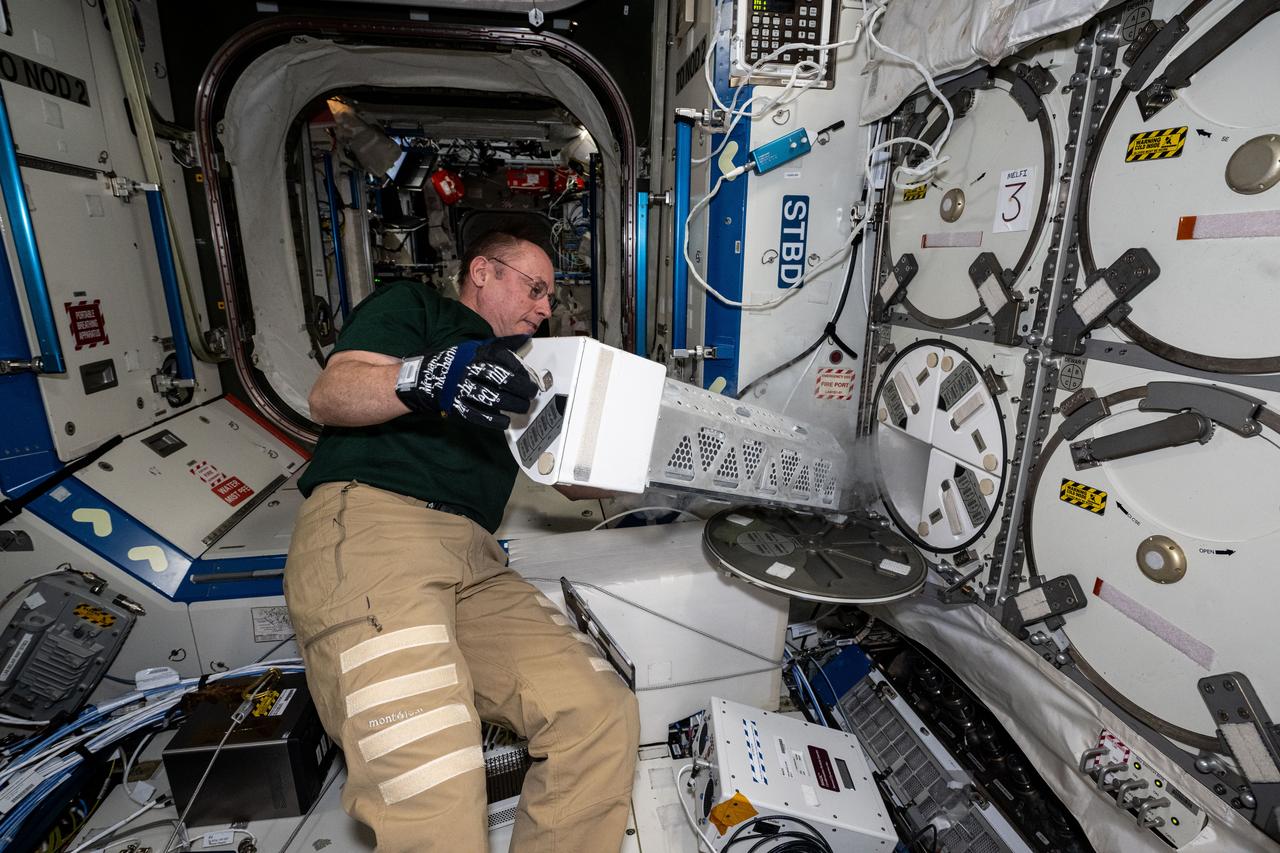
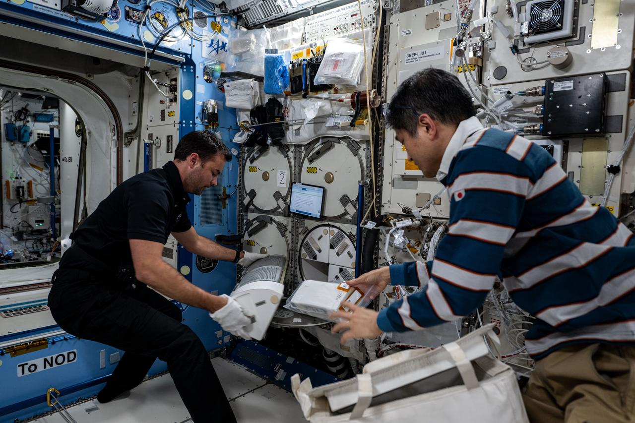
iss073e0548958 (Aug. 29, 2025) --- NASA astronaut and Expedition 73 Flight Engineer Mike Fincke inserts a cryogenic storage unit, called a dewar, containing blood samples collected from a crew member into a science freezer for preservation and later analysis. The Minus Eighty-Degree Laboratory Freezer for International Space Station, or MELFI, is a research freezer that maintains experiment samples at ultra-cold temperatures in microgravity.

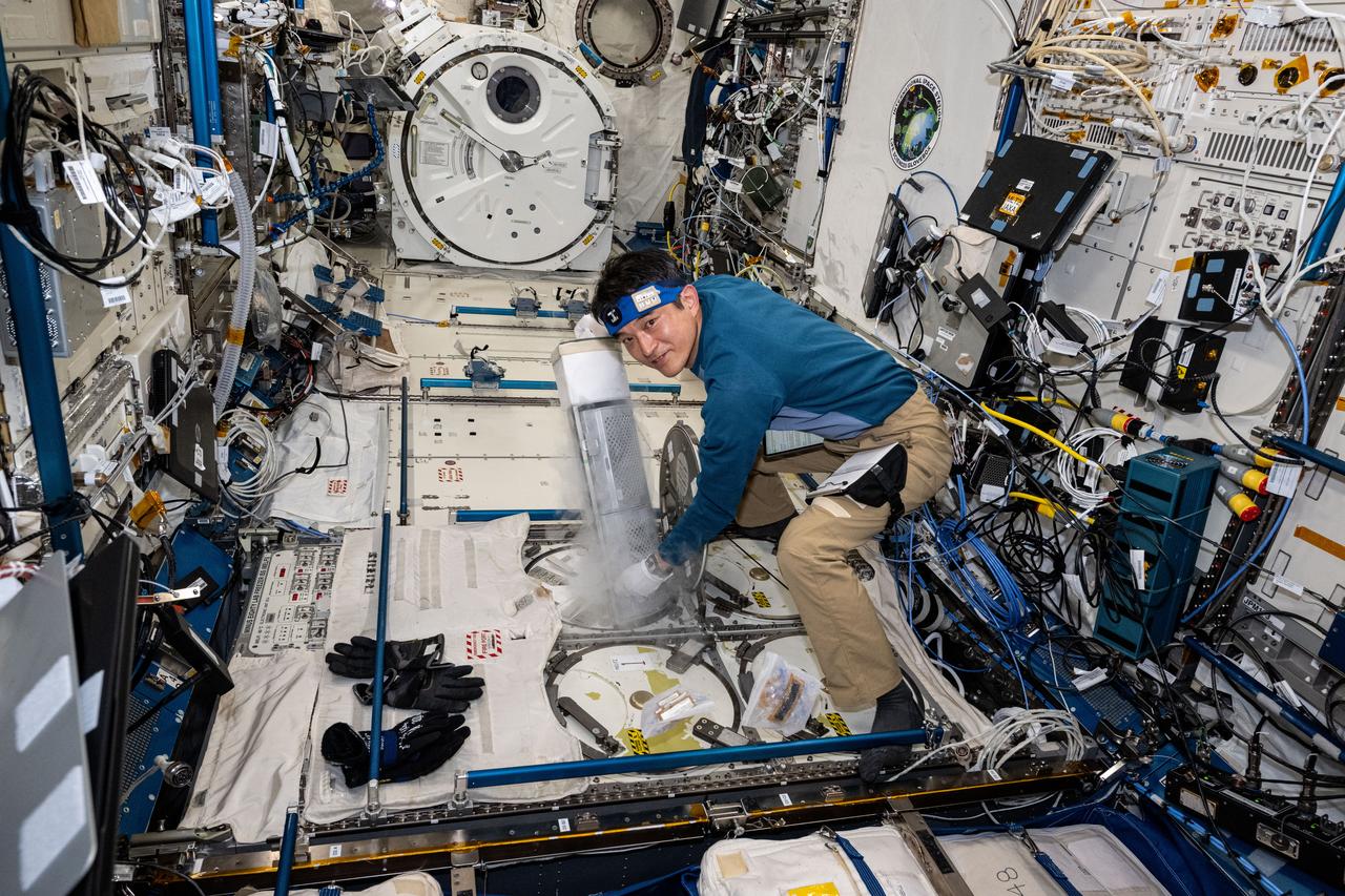
iss074e0590846 (May 12, 2026) --- NASA astronaut and Expedition 74 flight engineer Chris Williams inserts a cryogenic storage unit, called a dewar, into a science freezer aboard the International Space Station’s Kibo laboratory module. Earlier, Williams had loaded the dewar with ice bricks that help keep scientific samples extremely cold inside the ultra‑cold freezer, known as the Minus Eighty‑Degree Laboratory Freezer for the International Space Station, or MELFI. Credit: NASA/Chris Williams
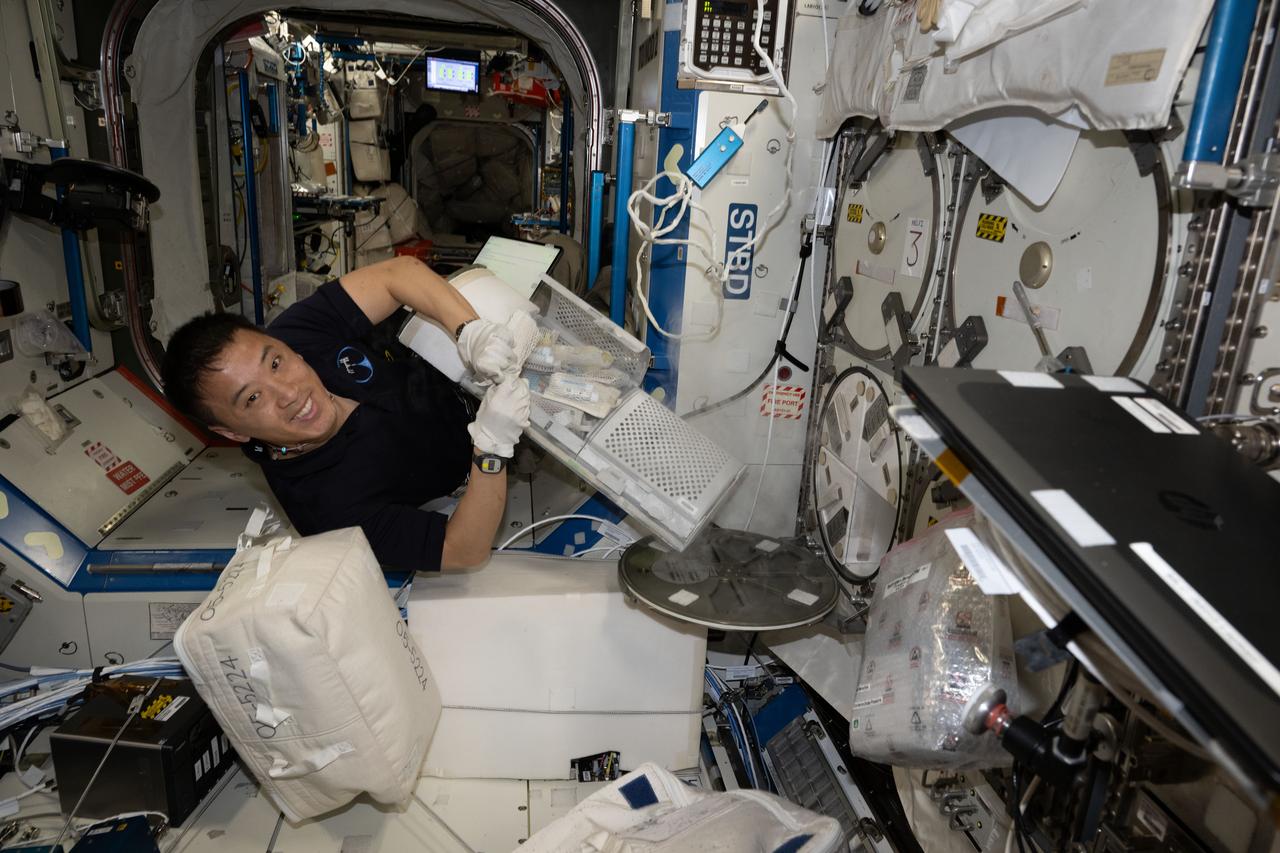
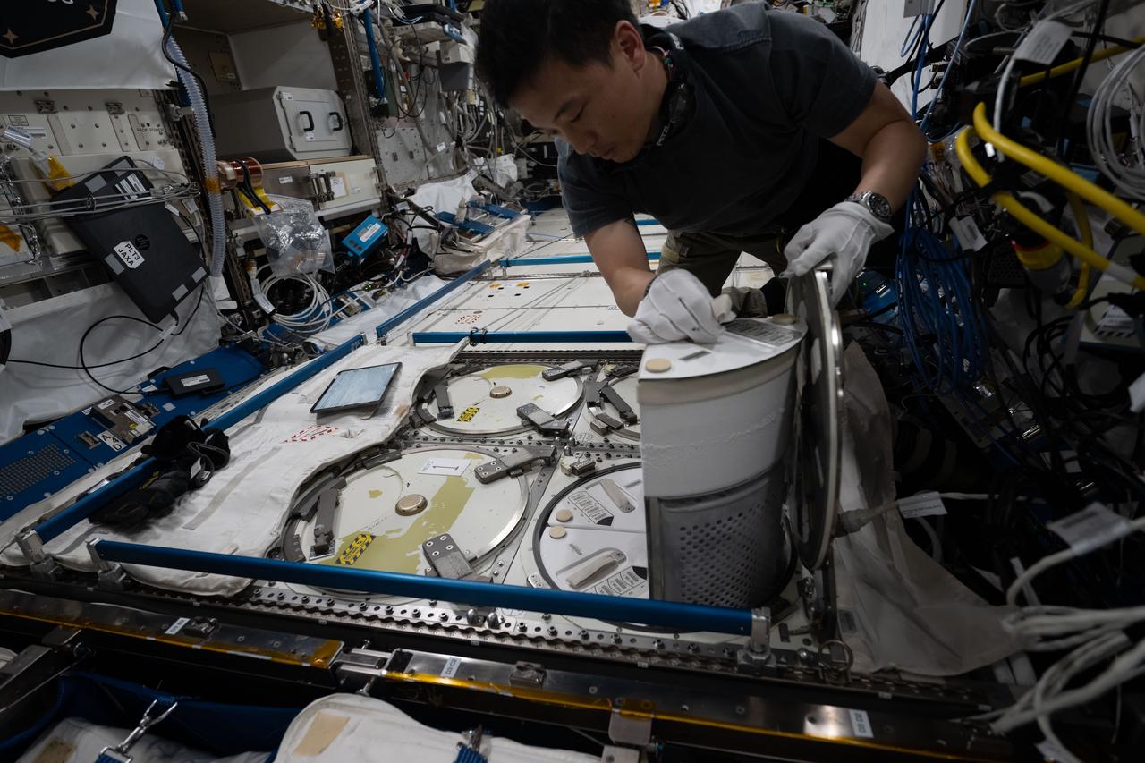
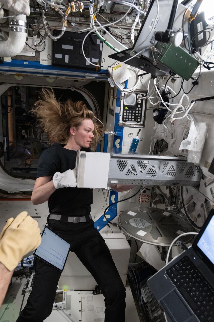
iss073e0135008 (May 29, 2025) --- NASA astronaut and Expedition 73 Flight Engineer Jonny Kim stows research samples inside a cryogenic storage unit for installation inside a science freezer for preservation inside the International Space Station's Destiny laboratory module. Offically called the Minus Eighty-Degree Laboratory Freezer for ISS, or MELFI, the ultra-cold storage unit enables space biology research by preserving biological samples for analysis including blood, saliva, urine, microbes, and more.
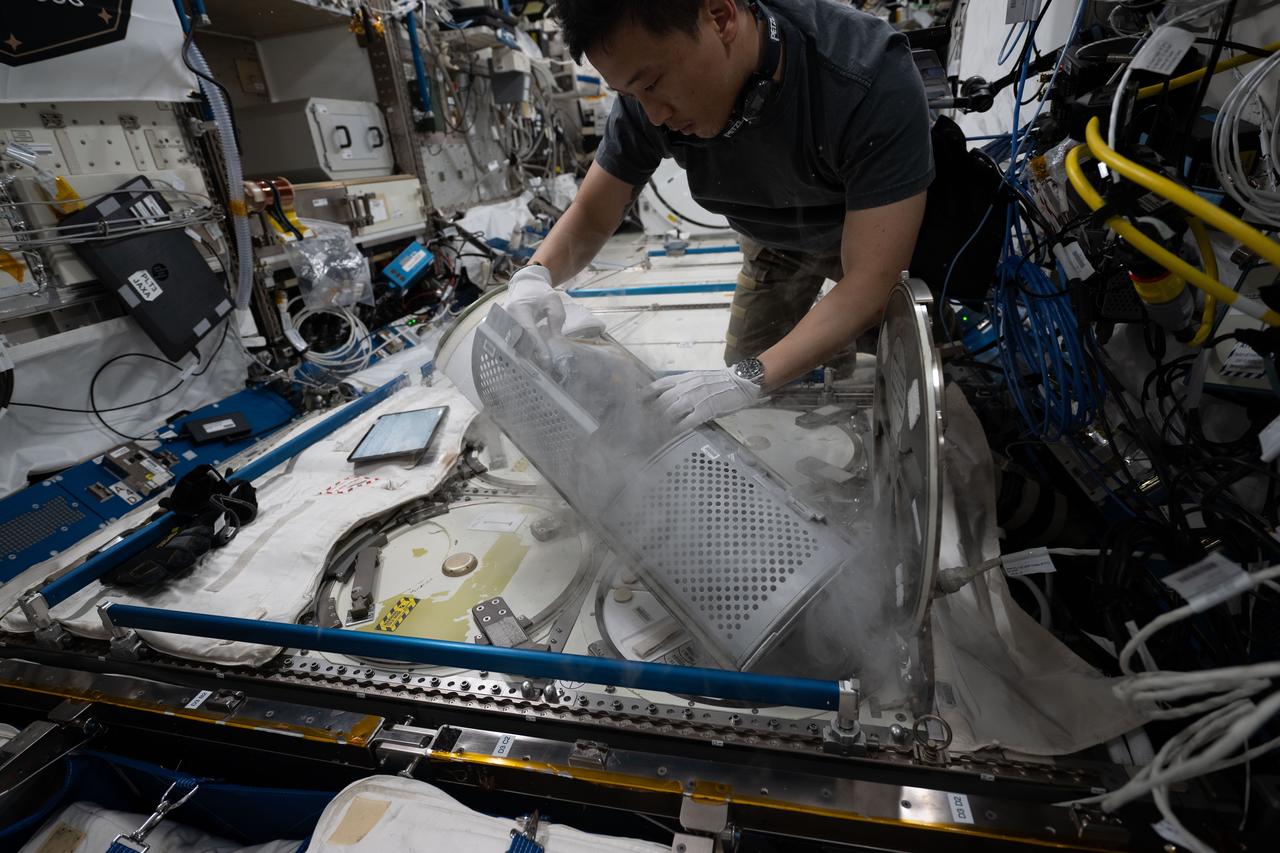
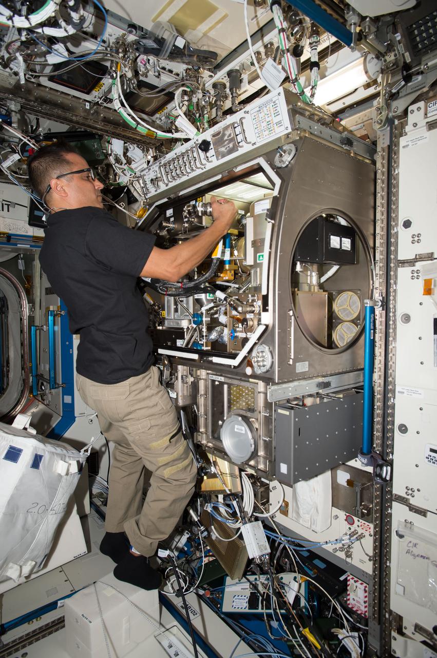
iss073e0071617 (May 16, 2025) --- NASA astronaut and Expedition 73 Flight Engineer Jonny Kim removes a cryogenic storage unit, called a dewar, containing frozen protein crystal samples from a science freezer located inside International Space Station's Kibo laboratory module. The research activities were part of a technology demonstration potentially enabling the synthesis of medications during deep space missions and improving the pharmaceutical industry on Earth.
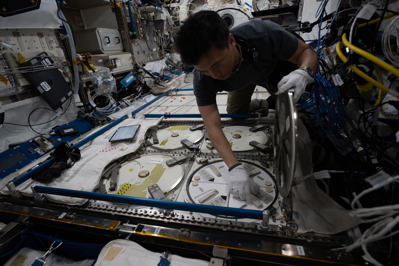
iss073e0071610 (May 16, 2025) --- NASA astronaut and Expedition 73 Flight Engineer Jonny Kim removes a cryogenic storage unit, called a dewar, containing frozen protein crystal samples from a science freezer located inside International Space Station's Kibo laboratory module. The research activities were part of a technology demonstration potentially enabling the synthesis of medications during deep space missions and improving the pharmaceutical industry on Earth.
iss073e0071611 (May 16, 2025) --- NASA astronaut and Expedition 73 Flight Engineer Jonny Kim removes a cryogenic storage unit, called a dewar, containing frozen protein crystal samples from a science freezer located inside International Space Station's Kibo laboratory module. The research activities were part of a technology demonstration potentially enabling the synthesis of medications during deep space missions and improving the pharmaceutical industry on Earth.
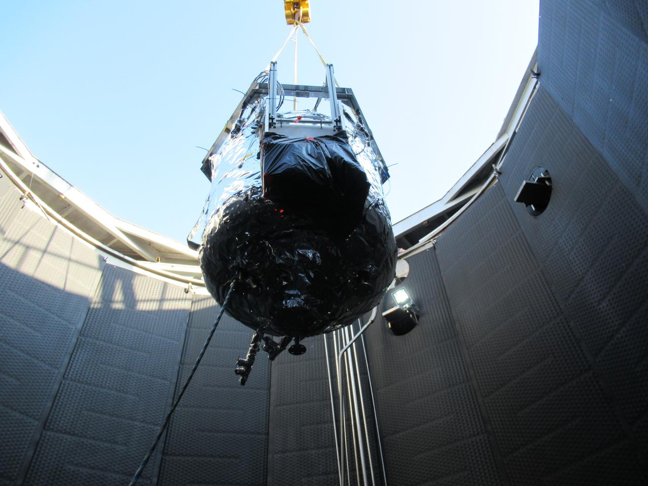
iss058e015157 (2/19/2019) --- Photo documentation of the Robotic Refueling Mission 3 (RRM3) hardware in the KIBO module aboard the International Space Station (ISS). Robotic Refueling Mission 3 (RRM3) demonstrates the first transfer and long term storage of liquid methane, a cryogenic fluid, in microgravity. The ability to replenish and store cryogenic fluids, which can function as a fuel or coolant, can help enable long duration journeys to destinations like the Moon and Mars.

A person observes the computational Fluid Dynamics solution for cryogenic storage tank mixing inside the Glenn Reconfigurable User-interface and Virtual Reality Exploration on October 18, 2023. The GRUVE Lab provides a fully interactive virtual reality space in which to observe and analyze data and environments. Photo Credit: (NASA/Sara Lowthian-Hanna)

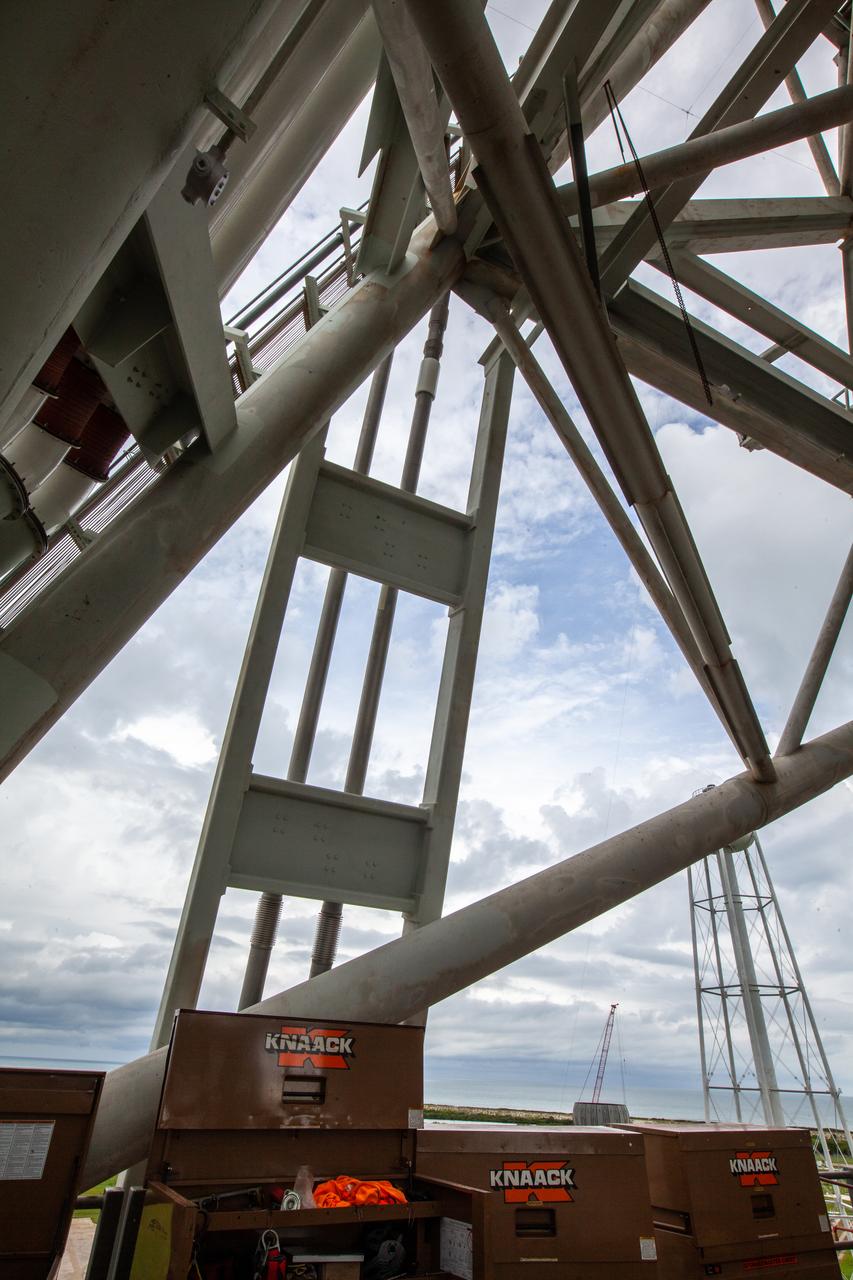
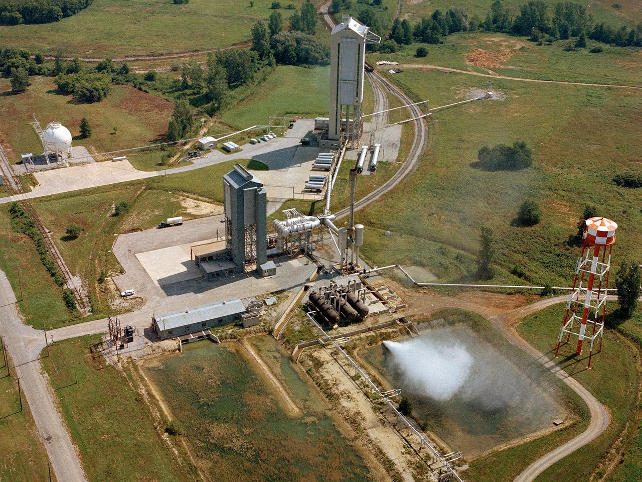
KENNEDY SPACE CENTER, Fla. -- This aerial photo captures Launch Pads 39B (left) and 39A (right). Space Shuttle Discovery waits on pad 39A for launch on mission STS-92 Oct. 5, 2000. The ball-shaped structures at left of the pads are storage tanks of the cryogenic liquid propellants for the orbiter’s main engines
KENNEDY SPACE CENTER, Fla. -- This aerial photo captures Launch Pads 39B (left) and 39A (right). Space Shuttle Discovery waits on pad 39A for launch on mission STS-92 Oct. 5, 2000. The ball-shaped structures at left of the pads are storage tanks of the cryogenic liquid propellants for the orbiter’s main engines
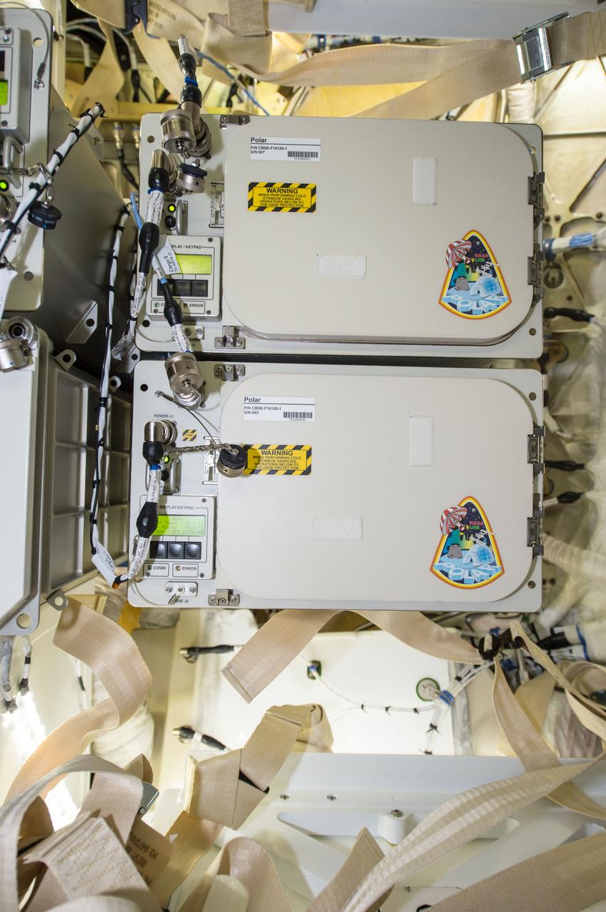
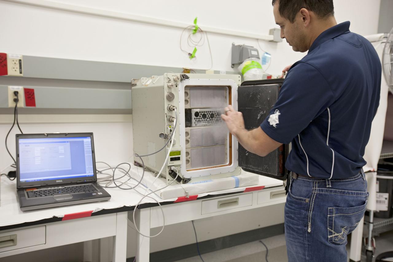
iss052e010012 (6/30/2017) --- A view of the final configuration of the Polar 7 after installation in SpaceX Dragon-11 module. Polar is a Cold Stowage managed facility that provides transport and storage of science samples at cryogenic temperatures (-80ºC) to and from the International Space Station (ISS).

NACOGDOCHES, Texas -- A round 40-inch aluminum storage tank from space shuttle Columbia's Power Reactant and Storage Distribution System rests on the edge of Lake Nacogdoches in Texas. Lower lake water levels due to a local drought allowed the debris to become exposed. Columbia was destroyed during re-entry at the conclusion of the STS-107 mission in 2003. Approximately 38 to 40 percent of Columbia was recovered following the accident in a half-million-acre search area which extended from eastern Texas and to western Louisiana. This tank is one of 18 cryogenic liquid storage tanks that flew aboard Columbia. The tank is not hazardous to people or the environment and will be transported to NASA's Kennedy Space Center for storage inside the Vehicle Assembly Building with the rest of the recovered Columbia debris. For information on STS-107 and the Columbia accident, visit http://www.nasa.gov/columbia/home/index.html. Photo credit: Nacogdoches Police Dept.
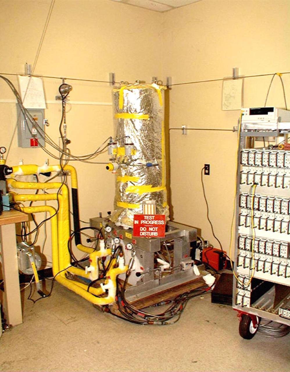
Engineers complete a test of the Ground Operations Demo Unit for liquid hydrogen at NASA's Kennedy Space Center in Florida. The system includes a 33,000 gallon liquid hydrogen storage tank with an internal cold heat exchanger supplied from a cryogenic refrigerator. The primary goal of the testing is to achieve a liquid hydrogen zero boil-off capability. The system was designed, installed and tested by a team of civil servants and contractors from the center's Cryogenic Test Laboratory, with support from engineers at NASA's Glenn Research Center in Cleveland and Stennis Space Center in Mississippi. It may be applicable for use by the Ground Systems Development and Operations Program at Launch Pad 39B.
iss058e015664 (2/19/2019) --- NASA astronaut Anne McClain and Canadian Space Agency (CSA) astronaut David Saint-Jacques shown during the installation of the Robotics Refueling Mission (RRM)-3 on the JEM Airlock slide table in the KIBO module aboard the International Space Station (ISS). Robotic Refueling Mission 3 (RRM3) demonstrates the first transfer and long term storage of liquid methane, a cryogenic fluid, in microgravity. The ability to replenish and store cryogenic fluids, which can function as a fuel or coolant, can help enable long duration journeys to destinations like the Moon and Mars.
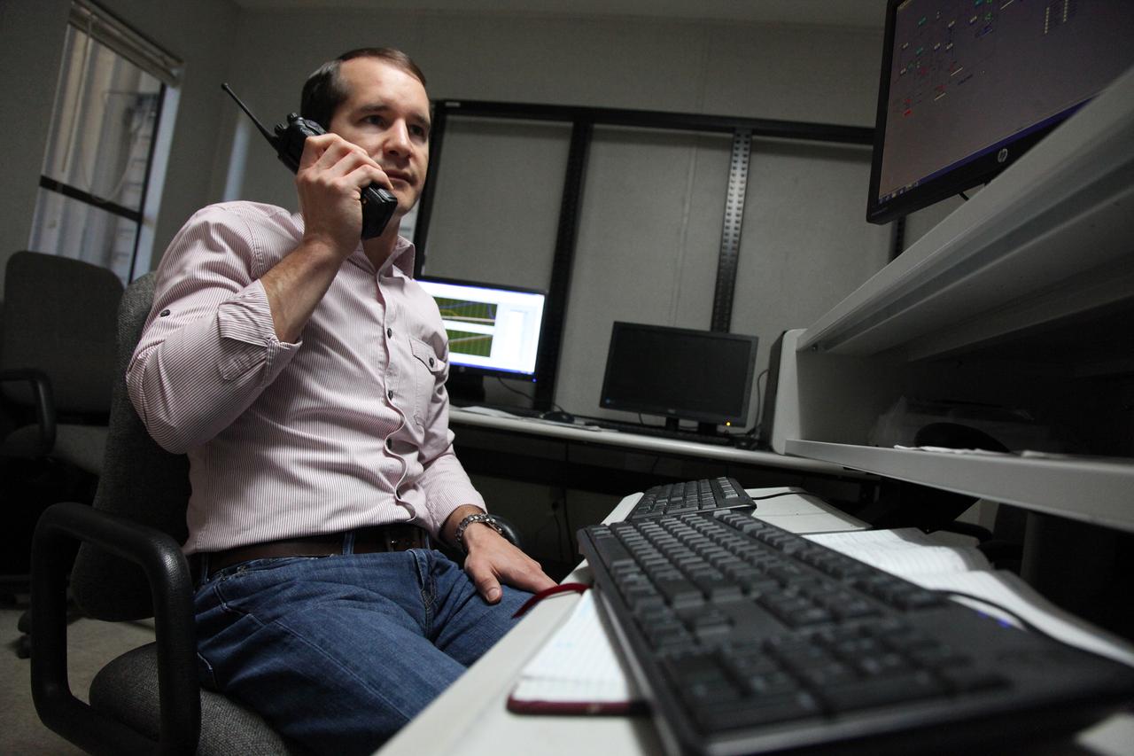
Inside a control building at NASA's Kennedy Space Center in Florida, Adam Swinger, cryogenic research engineer in the Exploration Research and Technology Directorate, communicates with team members during a test of the Ground Operations Demo Unit for liquid hydrogen. The system includes a 33,000 gallon liquid hydrogen storage tank with an internal cold heat exchanger supplied from a cryogenic refrigerator. The primary goal of the testing is to achieve a liquid hydrogen zero boil-off capability. The system was designed, installed and tested by a team of civil servants and contractors from the center's Cryogenic Test Laboratory, with support from engineers at NASA's Glenn Research Center in Cleveland and Stennis Space Center in Mississippi. It may be applicable for use by the Ground Systems Development and Operations Program at Launch Pad 39B.

On Dec. 19, 2018, Bill Hill, deputy associate administrator for Exploration Systems Development at NASA Headquarters in Washington, speaks during a groundbreaking ceremony for a new liquid hydrogen tank for Launch Complex 39B at the agency's Kennedy Space Center. The storage facility will hold 1.25 million gallons of the propellant for NASA's Space Launch System rocket designed to boost the agency's Orion spacecraft, sending humans to distant destinations such as the Moon and Mars.
On Dec. 19, 2018, NASA and contractor managers gathered for a groundbreaking ceremony for a new liquid hydrogen tank for Launch Complex 39B at NASA's Kennedy Space Center. The storage facility will hold 1.25 million gallons of the propellant for NASA's Space Launch System rocket designed to boost the agency's Orion spacecraft, sending humans to distant destinations such as the Moon and Mars.
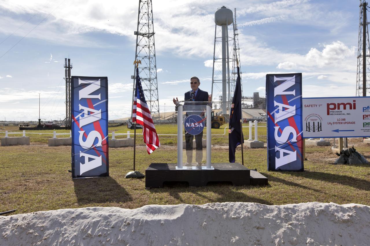
On Dec. 19, 2018, Kennedy Space Center Director Bob Cabana speaks during a groundbreaking ceremony for a new liquid hydrogen tank for Launch Complex 39B at the space center. The storage facility will hold 1.25 million gallons of the propellant for NASA's Space Launch System rocket designed to boost the agency's Orion spacecraft, sending humans to distant destinations such as the Moon and Mars.
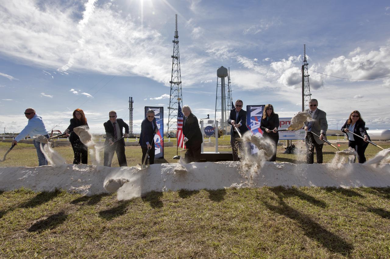
On Dec. 19, 2018, at NASA Kennedy Space Center's Launch Complex 39B, agency and contractor managers break ground for a new liquid hydrogen tank. Participating, from the left, are Todd Gray, president of Precision Mechanical, prime contractor for the project; Charlie Blackwell-Thompson, launch director; Shawn Quinn, director of Engineering; Bob Cabana, center director; Bill Hill, deputy associate administrator for Exploration Systems Development at NASA Headquarters in Washington; Mike Bolger, program manager for Exploration Ground Systems (EGS); Jennifer Kunz, deputy program manager for EGS, Andy Allen, general manager for Jacobs, NASA's Test and Operations Support Contractor; and Regina Spellman, launch pad senior project manager in EGS. The storage facility will hold 1.25 million gallons of the propellant for NASA's Space Launch System rocket designed to boost the agency's Orion spacecraft, sending humans to distant destinations such as the Moon and Mars.

On Dec. 19, 2018, NASA Launch Director Charlie Blackwell-Thompson speaks during a groundbreaking ceremony for a new liquid hydrogen tank for Launch Complex 39B at the agency's Kennedy Space Center. The storage facility will hold 1.25 million gallons of the propellant for NASA's Space Launch System rocket designed to boost the agency's Orion spacecraft, sending humans to distant destinations such as the Moon and Mars.
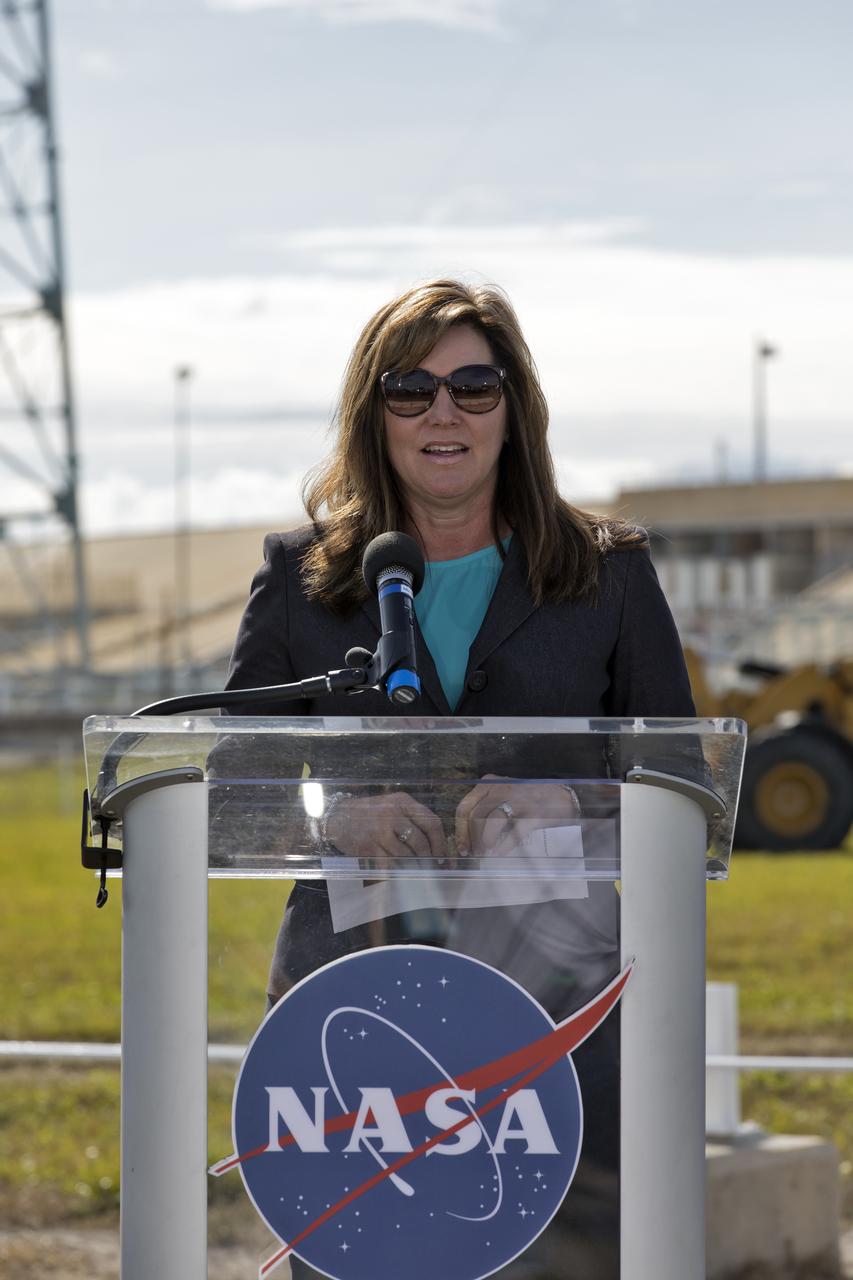
On Dec. 19, 2018, Jennifer Kunz, deputy program manager for Exploration Ground Systems, speaks during a groundbreaking ceremony for a new liquid hydrogen tank for Launch Complex 39B at the agency's Kennedy Space Center. The storage facility will hold 1.25 million gallons of the propellant for NASA's Space Launch System rocket designed to boost the agency's Orion spacecraft, sending humans to distant destinations such as the Moon and Mars.
iss073e0251266 (June 27, 2025) --- Axiom Mission 4 private astronaut Tibor Kapu (at left) from Hungary loads a research sample-packed cryogenic storage unit, called a dewar, into a science freezer aboard the International Space Station's Kibo laboratory module. Expedition 73 Commander Takuya Onishi from JAXA (Japan Aerospace Exploration Agency) assisted Kapu during the science experiment transfers from the SpaceX Dragon crew spacecraft into the orbital outpost.
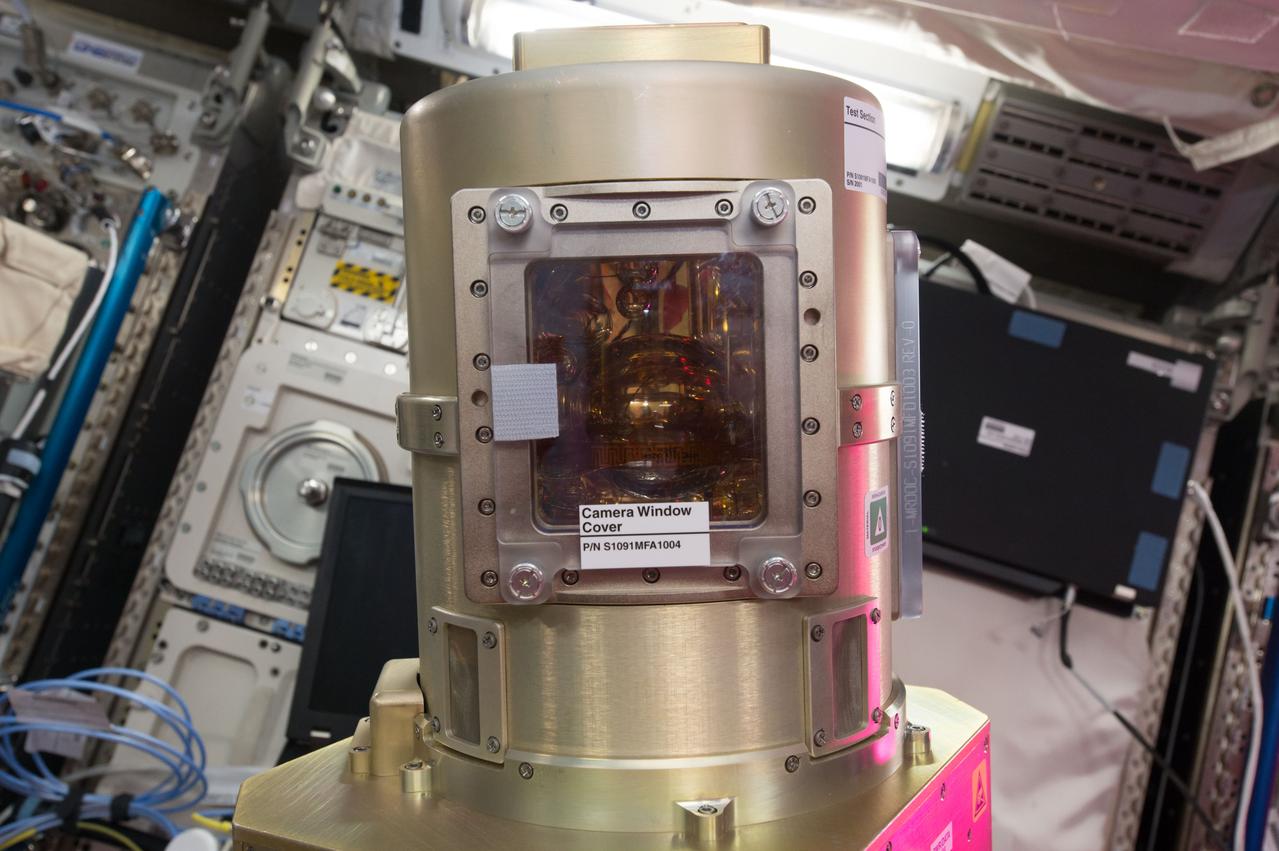
iss051e028301 (4/25/2017) --- A view of the Zero Boil-Off Tank (ZBOT) experiment Vacuum Jacket Camera Window Cover hardware. Zero Boil-Off Tank (ZBOT) uses an experimental fluid to test active heat removal and forced jet mixing as alternative means for controlling tank pressure for volatile fluids. Results from the investigation improve models used to design tanks for long-term cryogenic liquid storage, which are essential in biotechnology, medicine, industrial, and many other applications on Earth.
iss072e861307 (March 27, 2025) --- JAXA (Japan Aerospace Exploration Agency) astronaut and Expediion 72 Flight Engineer Takuya Onishi inserts a cryogenic storage unit, called a dewar, containing blood samples collected from a crew member into a science freezer for preservation and later analysis. The Minus Eighty-Degree Laboratory Freezer for International Space Station, or MELFI, is a research freezer that maintains experiment samples at ultra-cold temperatures in microgravity.
KENNEDY SPACE CENTER, Fla. -- Just after dawn, Launch Pad 39A is caught in silhouette and reflected in the water nearby. On the pad is Space Shuttle Discovery, waiting for launch on mission STS-92 Oct. 5, 2000. At the left of the pad is the 300,000-gallon water tank that is part of the sound suppression system during launches. At far left, the ball-shaped structure is a storage tank for one of the cryogenic liquid propellants of the orbiter’s main engines
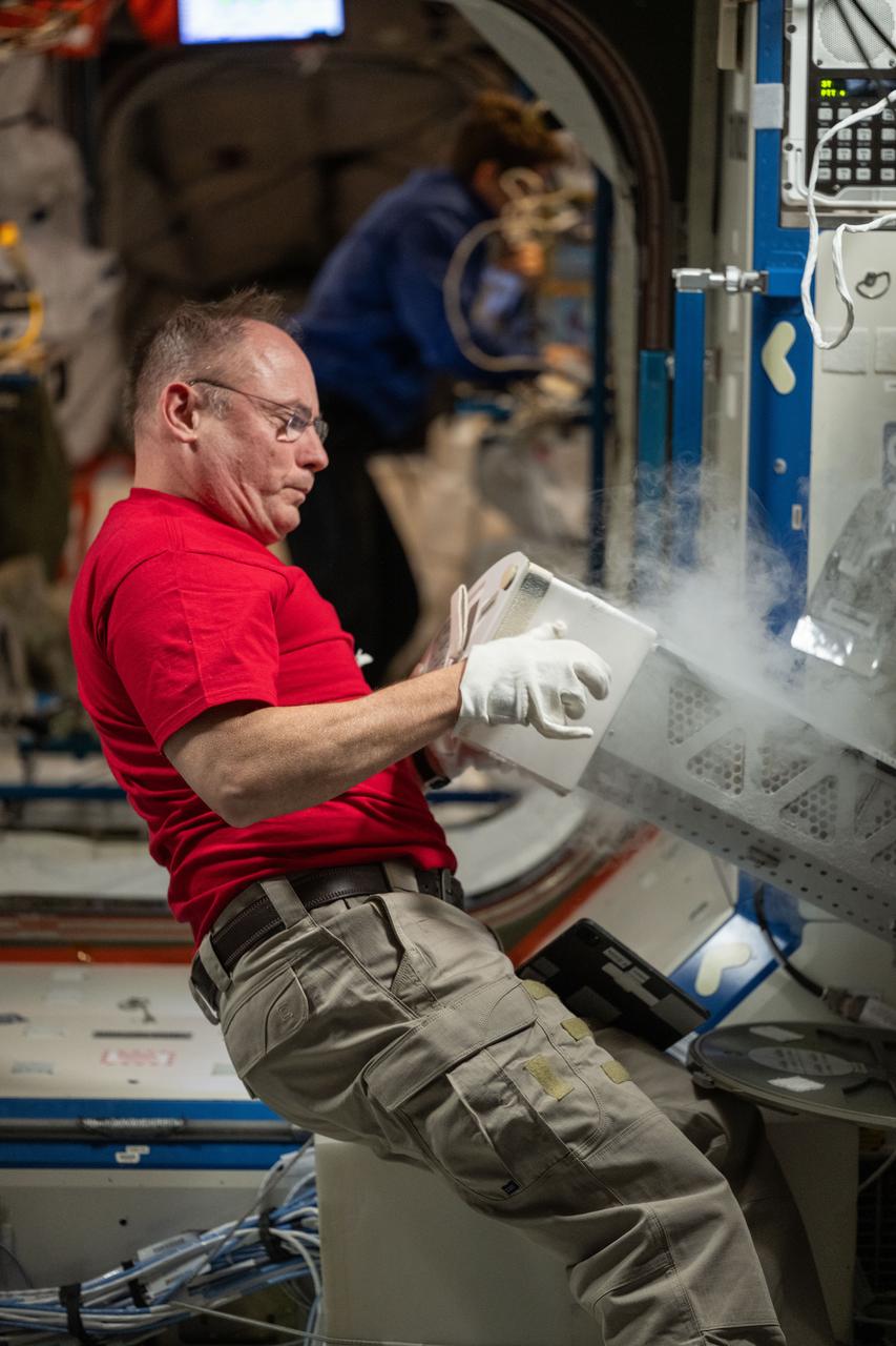
iss073e0424037 (Aug. 7, 2025) --- NASA astronaut and Expedition 73 Flight Engineer Mike Fincke inserts a cryogenic storage unit, called a dewar, containing blood samples collected from a crew member into a science freezer for preservation and later analysis. The Minus Eighty-Degree Laboratory Freezer for International Space Station, or MELFI, is a research freezer that maintains experiment samples at ultra-cold temperatures in microgravity.
iss072e808609 (March 20, 2025) --- NASA astronaut and Expedition 72 Flight Engineer Nichole Ayers inserts a cryogenic storage unit, called a dewar, containing blood samples collected from a crew member into a science freezer for preservation and later analysis. The Minus Eighty-Degree Laboratory Freezer for International Space Station, or MELFI, is a research freezer that maintains experiment samples at ultra-cold temperatures in microgravity.
iss053e027113 (9/18/2017) --- NASA astronaut Joe Acaba during the Zero Boil-Off Tank Hardware Setup in the Microgravity Science Glovebox (MSG). Zero Boil-Off Tank (ZBOT) uses an experimental fluid to test active heat removal and forced jet mixing as alternative means for controlling tank pressure for volatile fluids. Results from the investigation improve models used to design tanks for long-term cryogenic liquid storage, which are essential in biotechnology, medicine, industrial, and many other applications on Earth.
iss048e065818 (8/24/2016) --- NASA astonaut Kate Rubins poses for a photo next to Polar Facilities 2 and 4 installed in the SpaceX Dragon Commercial Resupply Services-9 (CRS-9) spacecraft for return to Earth. Polar is a Cold Stowage managed facility that provides transport and storage of science samples at cryogenic temperatures (-80ºC) to and from the International Space Station (ISS).
CAPE CANAVERAL, Fla. – Near the Hypergolic Maintenance Facility at NASA’s Kennedy Space Center in Florida, a groundbreaking ceremony was held to mark the location of the Ground Operations Demonstration Unit Liquid Hydrogen, or GODU LH2, test site. From left, are Johnny Nguyen, Fluids Test and Technology Development branch chief Emily Watkins, engineering intern Jeff Walls, Engineering Services Contract, or ESC, Cryogenics Test Lab engineer Kelly Currin, systems engineer Stephen Huff and Rudy Werlink partially hidden, cryogenics engineers Angela Krenn, systems engineer Doug Hammond, command and control engineer in the electrical division William Notardonato, GODU LH2 project manager and Kevin Jumper, ESC Cryogenics Test Lab manager. The GODU LH2 test site is one of the projects in NASA’s Advanced Exploration Systems Program. The site will be used to demonstrate advanced liquid hydrogen systems that are cost and energy efficient ways to store and transfer liquid hydrogen during process, loading, launch and spaceflight. The main components of the site will be a storage tank and a cryogenic refrigerator. Photo credit: NASA/Dimitri Gerondidakis
Various materials are ready for testing in the Kennedy Space Center's cryogenics test bed laboratory. The cryogenics laboratory is expanding to a larger test bed facility in order to offer research and development capabilities that will benefit projects originating from KSC, academia and private industry. Located in KSC's industrial area, the lab is equipped with a liquid nitrogen flow test area to test and evaluate cryogenic valves, flow-meters and other handling equipment in field conditions. A 6,000-gallon tank supplies liquid to low-flow and high-flow test sections. KSC engineers and scientists can also build system prototypes and then field test and analyze them with the center's unique equipment. Expanded cryogenic infrastructure will posture the Space Coast to support biological and medical researchers who use liquid nitrogen to preserve and store human and animal cells and to destroy cancer tissue using cryosurgery; hospitals that use superconductive magnets cooled in liquid helium for magnetic resonance imaging (MRI); the food industry, which uses liquid nitrogen for freezing and long-term storage; as well as the next generation of reusable launch vehicles currently in development
Materials are being tested in the Kennedy Space Center's cryogenics test bed laboratory. The cryogenics laboratory is expanding to a larger test bed facility in order to offer research and development capabilities that will benefit projects originating from KSC, academia and private industry. Located in KSC's industrial area, the lab is equipped with a liquid nitrogen flow test area to test and evaluate cryogenic valves, flow-meters and other handling equipment in field conditions. A 6,000-gallon tank supplies liquid to low-flow and high-flow test sections. KSC engineers and scientists can also build system prototypes and then field test and analyze them with the center's unique equipment. Expanded cryogenic infrastructure will posture the Space Coast to support biological and medical researchers who use liquid nitrogen to preserve and store human and animal cells and to destroy cancer tissue using cryosurgery; hospitals that use superconductive magnets cooled in liquid helium for magnetic resonance imaging (MRI); the food industry, which uses liquid nitrogen for freezing and long-term storage; as well as the next generation of reusable launch vehicles currently in development
CAPE CANAVERAL, Fla. – Near the Hypergolic Maintenance Facility at NASA’s Kennedy Space Center in Florida, a groundbreaking ceremony was held to mark the location of the Ground Operations Demonstration Unit Liquid Hydrogen, or GODU LH2, test site. From left, are Johnny Nguyen, Fluids Test and Technology Development branch chief Emily Watkins, engineering intern Jeff Walls, Engineering Services Contract, or ESC, Cryogenics Test Lab engineer Kelly Currin, systems engineer Stephen Huff and Rudy Werlink partially hidden, cryogenics engineers Angela Krenn, systems engineer Doug Hammond, command and control engineer in the electrical division William Notardonato, GODU LH2 project manager and Kevin Jumper, ESC Cryogenics Test Lab manager. The GODU LH2 test site is one of the projects in NASA’s Advanced Exploration Systems Program. The site will be used to demonstrate advanced liquid hydrogen systems that are cost and energy efficient ways to store and transfer liquid hydrogen during process, loading, launch and spaceflight. The main components of the site will be a storage tank and a cryogenic refrigerator. Photo credit: NASA/Dimitri Gerondidakis
Technicians with Praxair pressurize the hydrogen trailer before offloading liquid hydrogen during a test of the Ground Operations Demo Unit for liquid hydrogen at NASA's Kennedy Space Center in Florida. The system includes a 33,000 gallon liquid hydrogen storage tank with an internal cold heat exchanger supplied from a cryogenic refrigerator. The primary goal of the testing is to achieve a liquid hydrogen zero boil-off capability. The system was designed, installed and tested by a team of civil servants and contractors from the center's Cryogenic Test Laboratory, with support from engineers at NASA's Glenn Research Center in Cleveland and Stennis Space Center in Mississippi. It may be applicable for use by the Ground Systems Development and Operations Program at Launch Pad 39B.
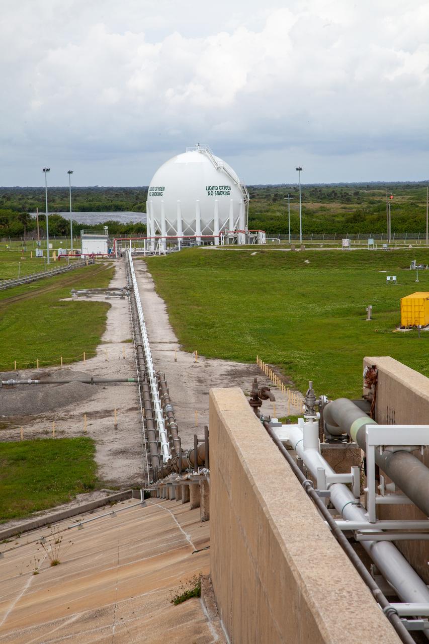
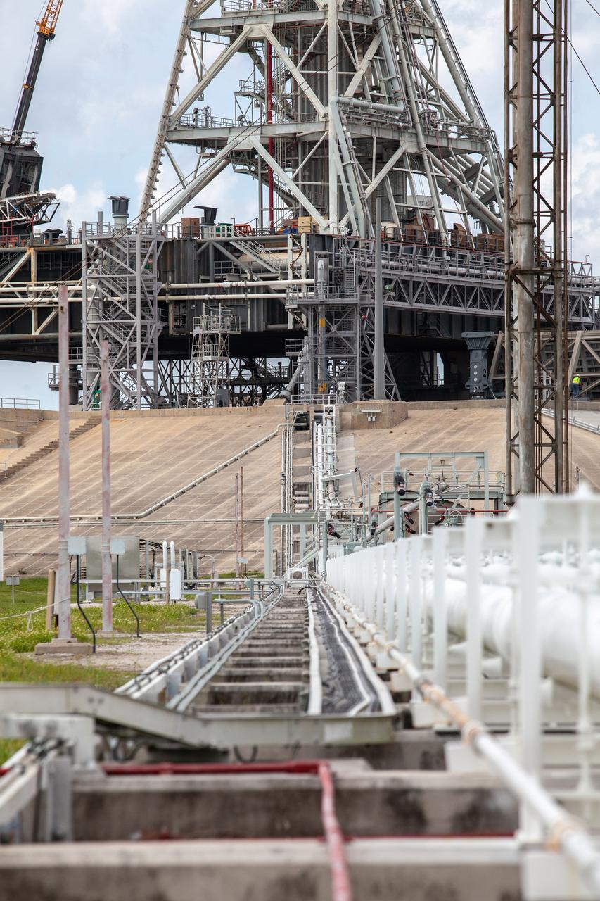
From left, liquid oxygen engineers Josh Jones, Jim Loup and Rene DeLaCruz on Kennedy Space Center’s Test Operations and Support Contract inspect equipment surrounding the liquid oxygen storage tank at Launch Pad 39B on Nov. 8, 2019. The agency’s Exploration Ground Systems oversaw testing of the pad’s cryogenic systems – the infrastructure that will support the flow of liquid hydrogen and liquid oxygen from the storage tanks to the Space Launch System (SLS) rocket – in preparation for the launch of SLS with the Orion spacecraft atop for the uncrewed Artemis I mission. Each of the liquid oxygen and liquid hydrogen tanks can hold more than 800,000 gallons of propellant. The liquid oxygen will require the use of pumps to push it from the tank to the rocket, while the lighter liquid hydrogen will make its way up to the pad using gaseous hydrogen to pressurize the sphere.
A liquid oxygen storage tank, with a view of the mobile launcher on the pad surface in the background, is photographed at Launch Pad 39B on Nov. 8, 2019, at NASA’s Kennedy Space Center in Florida. The agency’s Exploration Ground Systems oversaw testing of the pad’s cryogenic systems – the infrastructure that will support the flow of liquid hydrogen and liquid oxygen from the storage tanks to the Space Launch System (SLS) rocket – in preparation for the launch of SLS with the Orion spacecraft atop for the uncrewed Artemis I mission. Each of the liquid oxygen and liquid hydrogen tanks can hold more than 800,000 gallons of propellant. The liquid oxygen will require the use of pumps to push it from the tank to the rocket, while the lighter liquid hydrogen will make its way up to the pad using gaseous hydrogen to pressurize the sphere.

In this view, the cross country line that liquid oxygen will flow through can be seen stretching from the storage tank to the mobile launcher at Launch Pad 39B on Nov. 8, 2019, at NASA’s Kennedy Space Center in Florida. The agency’s Exploration Ground Systems oversaw testing of the pad’s cryogenic systems – the infrastructure that will send liquid hydrogen and liquid oxygen from the storage tanks to the Space Launch System (SLS) rocket – in preparation for the launch of SLS with the Orion spacecraft atop for the uncrewed Artemis I mission. Each of the liquid oxygen and liquid hydrogen tanks can hold more than 800,000 gallons of propellant. The liquid oxygen will require the use of pumps to push it from the tank to the rocket, while the lighter liquid hydrogen will make its way up to the pad using gaseous hydrogen to pressurize the sphere.
In this view, the cross country line that liquid hydrogen will flow through can be seen stretching from the storage tank to the mobile launcher (ML) at Launch Pad 39B on Nov. 8, 2019, at NASA’s Kennedy Space Center in Florida. The agency’s Exploration Ground Systems oversaw testing of the pad’s cryogenic systems – the infrastructure that will send liquid hydrogen and liquid oxygen from the storage tanks to the Space Launch System (SLS) rocket – in preparation for the launch of SLS with the Orion spacecraft atop for the uncrewed Artemis I mission. Each of the liquid hydrogen and liquid oxygen tanks can hold more than 800,000 gallons of propellant. The liquid hydrogen, lighter than liquid oxygen, will make its way from the tank to the rocket using gaseous hydrogen to pressurize the sphere at the time of launch, while the liquid oxygen will be sent to the rocket via pumps.
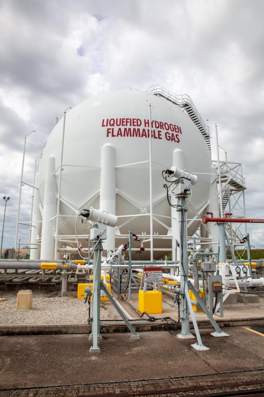
A liquid hydrogen storage tank is photographed at Launch Pad 39B on Nov. 8, 2019, at NASA’s Kennedy Space Center in Florida. The agency’s Exploration Ground Systems oversaw testing of the pad’s cryogenic systems – the infrastructure that will support the flow of liquid hydrogen and liquid oxygen from the storage tanks to the Space Launch System (SLS) rocket – in preparation for the launch of SLS with the Orion spacecraft atop for the uncrewed Artemis I mission. Each of the liquid hydrogen and liquid oxygen tanks can hold more than 800,000 gallons of propellant. The liquid hydrogen, lighter than liquid oxygen, will make its way from the tank to the rocket using gaseous hydrogen to pressurize the sphere at the time of launch, while the liquid oxygen will be sent to the rocket via pumps.
In this view from the pad surface at Kennedy Space Center’s Launch Pad 39B, the cross country line that liquid oxygen will flow through can be seen stretching from the pad to the liquid oxygen storage tank on Nov. 8, 2019. The agency’s Exploration Ground Systems oversaw testing of the pad’s cryogenic systems – the infrastructure that will support the flow of liquid hydrogen and liquid oxygen from the storage tanks to the Space Launch System (SLS) rocket – in preparation for the launch of SLS with the Orion spacecraft atop for the uncrewed Artemis I mission. Each of the liquid oxygen and liquid hydrogen tanks can hold more than 800,000 gallons of propellant. The liquid oxygen will require the use of pumps to push it from the tank to the rocket, while the lighter liquid hydrogen will make its way up to the pad using gaseous hydrogen to pressurize the sphere.
In this view, the cross country line that liquid hydrogen will flow through can be seen stretching from the storage tank to the mobile launcher (ML) at Launch Pad 39B on Nov. 8, 2019, at NASA’s Kennedy Space Center in Florida. The agency’s Exploration Ground Systems oversaw testing of the pad’s cryogenic systems – the infrastructure that will send liquid hydrogen and liquid oxygen from the storage tanks to the Space Launch System (SLS) rocket – in preparation for the launch of SLS with the Orion spacecraft atop for the uncrewed Artemis I mission. Each of the liquid hydrogen and liquid oxygen tanks can hold more than 800,000 gallons of propellant. The liquid hydrogen, lighter than liquid oxygen, will make its way from the tank to the rocket using gaseous hydrogen to pressurize the sphere at the time of launch, while the liquid oxygen will be sent to the rocket via pumps.
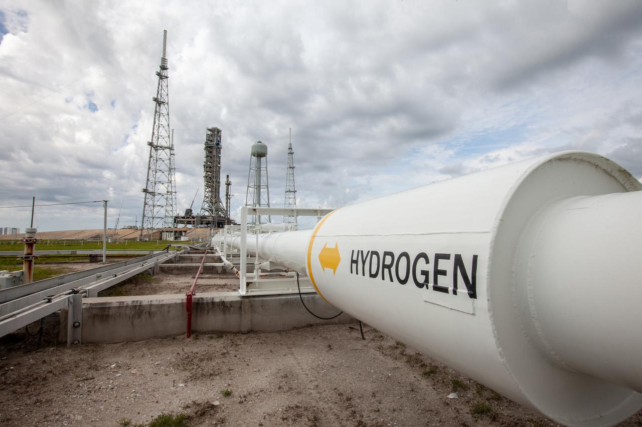
The cross country line that liquid hydrogen will flow through from the storage tank to the mobile launcher for the launch of NASA’s uncrewed Artemis I mission is photographed at Launch pad 39B on Nov. 8, 2019, at the agency’s Kennedy Space Center in Florida. NASA’s Exploration Ground Systems oversaw testing of the pad’s cryogenic systems – the infrastructure that will send the liquid hydrogen and liquid oxygen from the storage tanks to the Space Launch System (SLS) rocket – in preparation for the launch of SLS with the Orion spacecraft atop. Each of the liquid hydrogen and liquid oxygen tanks can hold more than 800,000 gallons of propellant. The liquid hydrogen, lighter than liquid oxygen, will make its way from the tank to the rocket using gaseous hydrogen to pressurize the sphere at the time of launch, while the liquid oxygen will be sent to the rocket via pumps.
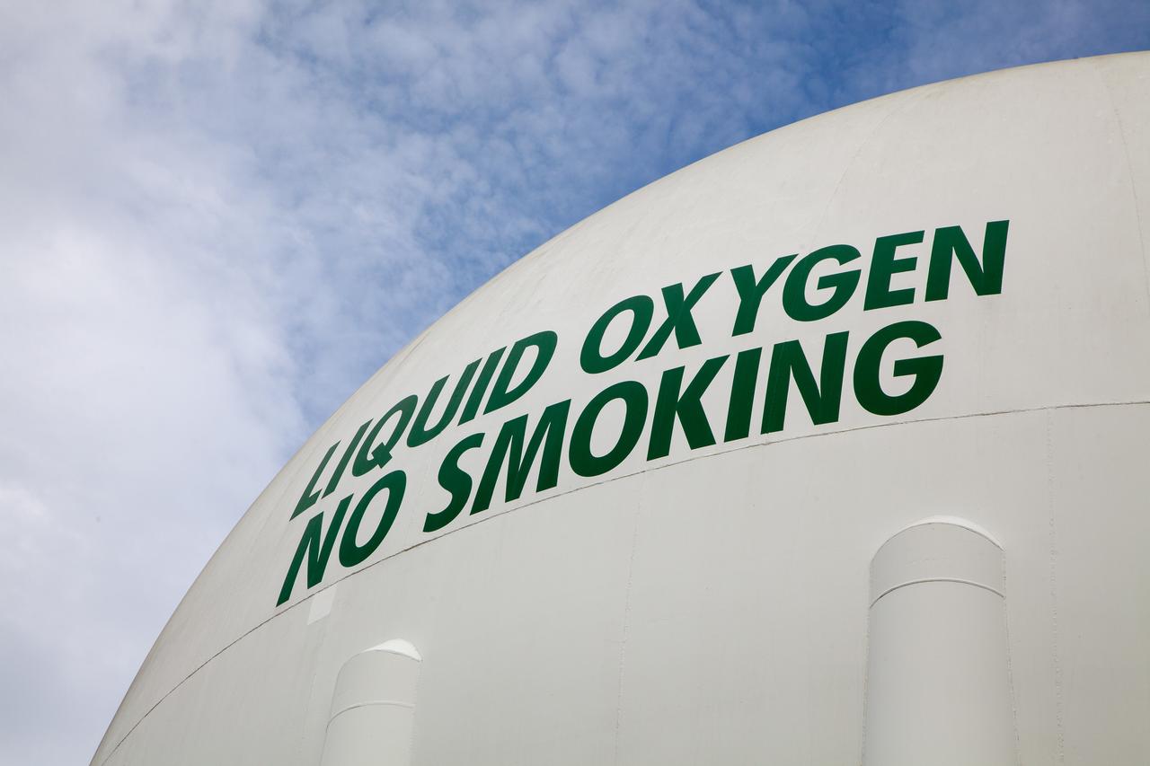
A liquid oxygen storage tank is photographed at Launch Pad 39B on Nov. 8, 2019, at NASA’s Kennedy Space Center in Florida. The agency’s Exploration Ground Systems oversaw testing of the pad’s cryogenic systems – the infrastructure that will support the flow of liquid hydrogen and liquid oxygen from the storage tanks to the Space Launch System (SLS) rocket – in preparation for the launch of SLS with the Orion spacecraft atop for the uncrewed Artemis I mission. Each of the liquid oxygen and liquid hydrogen tanks can hold more than 800,000 gallons of propellant. The liquid oxygen will require the use of pumps to push it from the tank to the rocket, while the lighter liquid hydrogen will make its way up to the pad using gaseous hydrogen to pressurize the sphere.
A liquid hydrogen storage tank is photographed at Launch Pad 39B on Nov. 8, 2019, at NASA’s Kennedy Space Center in Florida. The agency’s Exploration Ground Systems oversaw testing of the pad’s cryogenic systems – the infrastructure that will support the flow of liquid hydrogen and liquid oxygen from the storage tanks to the Space Launch System (SLS) rocket – in preparation for the launch of SLS with the Orion spacecraft atop for the uncrewed Artemis I mission. Each of the liquid hydrogen and liquid oxygen tanks can hold more than 800,000 gallons of propellant. The liquid hydrogen, lighter than liquid oxygen, will make its way from the tank to the rocket using gaseous hydrogen to pressurize the sphere at the time of launch, while the liquid oxygen will be sent to the rocket via pumps.
A liquid hydrogen storage tank, with a view of the mobile launcher on the pad surface in the background, is photographed at Launch Pad 39B on Nov. 8, 2019, at NASA’s Kennedy Space Center in Florida. The agency’s Exploration Ground Systems oversaw testing of the pad’s cryogenic systems – the infrastructure that will support the flow of liquid hydrogen and liquid oxygen from the storage tanks to the Space Launch System (SLS) rocket – in preparation for the launch of SLS with the Orion spacecraft atop for the uncrewed Artemis I mission. Each of the liquid hydrogen and liquid oxygen tanks can hold more than 800,000 gallons of propellant. The liquid hydrogen, lighter than liquid oxygen, will make its way from the tank to the rocket using gaseous hydrogen to pressurize the sphere at the time of launch, while the liquid oxygen will be sent to the rocket via pumps.
A liquid hydrogen storage tank is photographed at Launch Pad 39B on Nov. 8, 2019, at NASA’s Kennedy Space Center in Florida. The agency’s Exploration Ground Systems oversaw testing of the pad’s cryogenic systems – the infrastructure that will support the flow of liquid hydrogen and liquid oxygen from the storage tanks to the Space Launch System (SLS) rocket – in preparation for the launch of SLS with the Orion spacecraft atop for the uncrewed Artemis I mission. Each of the liquid hydrogen and liquid oxygen tanks can hold more than 800,000 gallons of propellant. The liquid hydrogen, lighter than liquid oxygen, will make its way from the tank to the rocket using gaseous hydrogen to pressurize the sphere at the time of launch, while the liquid oxygen will be sent to the rocket via pumps.
A liquid oxygen storage tank is photographed at Launch Pad 39B on Nov. 8, 2019, at NASA’s Kennedy Space Center in Florida. The agency’s Exploration Ground Systems oversaw testing of the pad’s cryogenic systems – the infrastructure that will support the flow of liquid hydrogen and liquid oxygen from the storage tanks to the Space Launch System (SLS) rocket – in preparation for the launch of SLS with the Orion spacecraft atop for the uncrewed Artemis I mission. Each of the liquid oxygen and liquid hydrogen tanks can hold more than 800,000 gallons of propellant. The liquid oxygen will require the use of pumps to push it from the tank to the rocket, while the lighter liquid hydrogen will make its way up to the pad using gaseous hydrogen to pressurize the sphere.

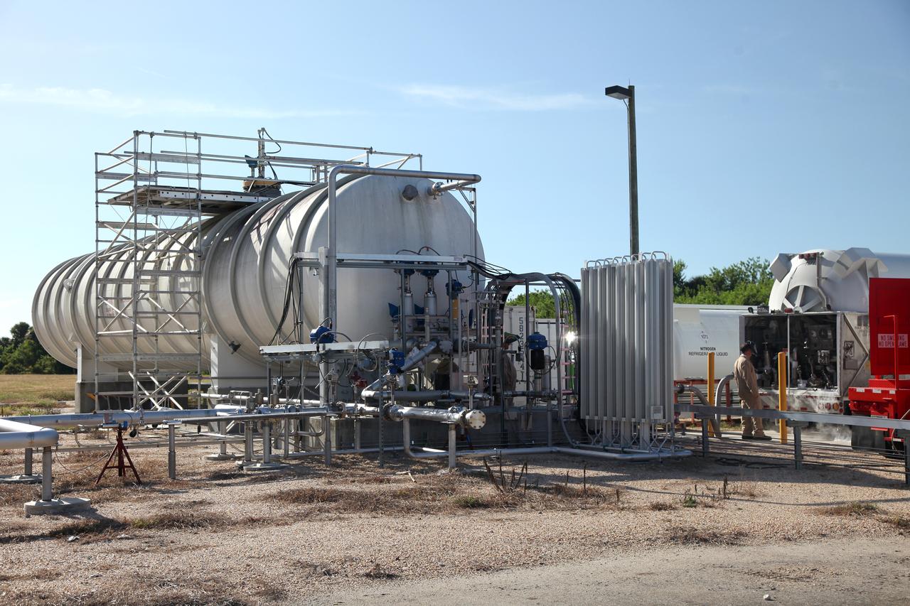
These photos show how teams at NASA’s Marshall Space Flight Center in Huntsville, Alabama, are testing an innovative approach to achieve zero boiloff storage of liquid hydrogen using two stages of active cooling, which could prevent the loss of valuable propellant during future long-duration spaceflight missions. Test teams installed the propellant tank in Test Stand 300 at NASA Marshall in early June, and the 90-day test campaign is scheduled to conclude in September. The tank is wrapped in a multi-layer insulation blanket that includes a thin aluminum heat shield fitted between layers. A second set of tubes, carrying helium at about minus 298 Fahrenheit, is integrated into the shield. This intermediate cooling layer intercepts and rejects incoming heat before it reaching the tank, easing the heat load on the tube-on-tank system. The Cryogenic Fluid Management Portfolio Project is a cross-agency team based at NASA Marshall and the agency’s Glenn Research Center in Cleveland. The cryogenic portfolio’s work is under NASA’s Technology Demonstration Missions Program, part of NASA’s Space Technology Mission Directorate, and is comprised of more than 20 individual technology development activities. For more information, contact NASA Marshall’s Office of Communications at 256-544-0034.
These photos show how teams at NASA’s Marshall Space Flight Center in Huntsville, Alabama, are testing an innovative approach to achieve zero boiloff storage of liquid hydrogen using two stages of active cooling, which could prevent the loss of valuable propellant during future long-duration spaceflight missions. Test teams installed the propellant tank in Test Stand 300 at NASA Marshall in early June, and the 90-day test campaign is scheduled to conclude in September. The tank is wrapped in a multi-layer insulation blanket that includes a thin aluminum heat shield fitted between layers. A second set of tubes, carrying helium at about minus 298 Fahrenheit, is integrated into the shield. This intermediate cooling layer intercepts and rejects incoming heat before it reaching the tank, easing the heat load on the tube-on-tank system. The Cryogenic Fluid Management Portfolio Project is a cross-agency team based at NASA Marshall and the agency’s Glenn Research Center in Cleveland. The cryogenic portfolio’s work is under NASA’s Technology Demonstration Missions Program, part of NASA’s Space Technology Mission Directorate, and is comprised of more than 20 individual technology development activities. For more information, contact NASA Marshall’s Office of Communications at 256-544-0034.
These photos show how teams at NASA’s Marshall Space Flight Center in Huntsville, Alabama, are testing an innovative approach to achieve zero boiloff storage of liquid hydrogen using two stages of active cooling, which could prevent the loss of valuable propellant during future long-duration spaceflight missions. Test teams installed the propellant tank in Test Stand 300 at NASA Marshall in early June, and the 90-day test campaign is scheduled to conclude in September. The tank is wrapped in a multi-layer insulation blanket that includes a thin aluminum heat shield fitted between layers. A second set of tubes, carrying helium at about minus 298 Fahrenheit, is integrated into the shield. This intermediate cooling layer intercepts and rejects incoming heat before it reaching the tank, easing the heat load on the tube-on-tank system. The Cryogenic Fluid Management Portfolio Project is a cross-agency team based at NASA Marshall and the agency’s Glenn Research Center in Cleveland. The cryogenic portfolio’s work is under NASA’s Technology Demonstration Missions Program, part of NASA’s Space Technology Mission Directorate, and is comprised of more than 20 individual technology development activities. For more information, contact NASA Marshall’s Office of Communications at 256-544-0034.
CAPE CANAVERAL, Fla. – At the Courtyard by Marriott hotel in Cocoa Beach, Fla., Pat Simpkins, director of Engineering and Technology at Kennedy Space Center talks to participants in the room and those participating online during the Third International Workshop on Lunar Superconductor Applications. The workshop included presentations from several engineers and researchers at Kennedy Space Center. The three-day workshop included presentations from speakers throughout the country and focused on Lunar in-situ resource utilization, NASA’s Lunar Ice Prospector called RESOLVE, CubeSats, cryogenic storage and many other topics related to lunar exploration. Photo credit: NASA_Jim Grossmann
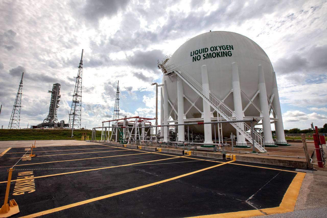
KENNEDY SPACE CENTER, Fla. -- A long view of Launch Complex 39 is caught by the early morning sun. Left of center is Launch Pad 39A with Space Shuttle Discovery. At its left is the 300,000-gallon water tank that is part of the sound suppression system. Hoses from the tank can be seen coiling under the pad, next to the opening of the flame trench, part of the flame detector system. In the foreground is a retention pond; another is at right center. At far right, the ball-shaped structure is a 850,000-gallon storage tank for the cryogenic liquid oxygen, one of the propellants of the orbiter’s main engines. On the horizon can be seen the 525-foot tall Vehicle Assembly Building
CAPE CANAVERAL, Fla. – At the Courtyard by Marriott hotel in Cocoa Beach, Fla., William Larson, retired NASA ISRU project manager, talks to participants in the room and those participating online during the Third International Workshop on Lunar Superconductor Applications. The workshop included presentations from several engineers and researchers at Kennedy Space Center. The three-day workshop included presentations from speakers throughout the country and focused on Lunar in-situ resource utilization, NASA’s Lunar Ice Prospector called RESOLVE, CubeSats, cryogenic storage and many other topics related to lunar exploration. Photo credit: NASA_Jim Grossmann
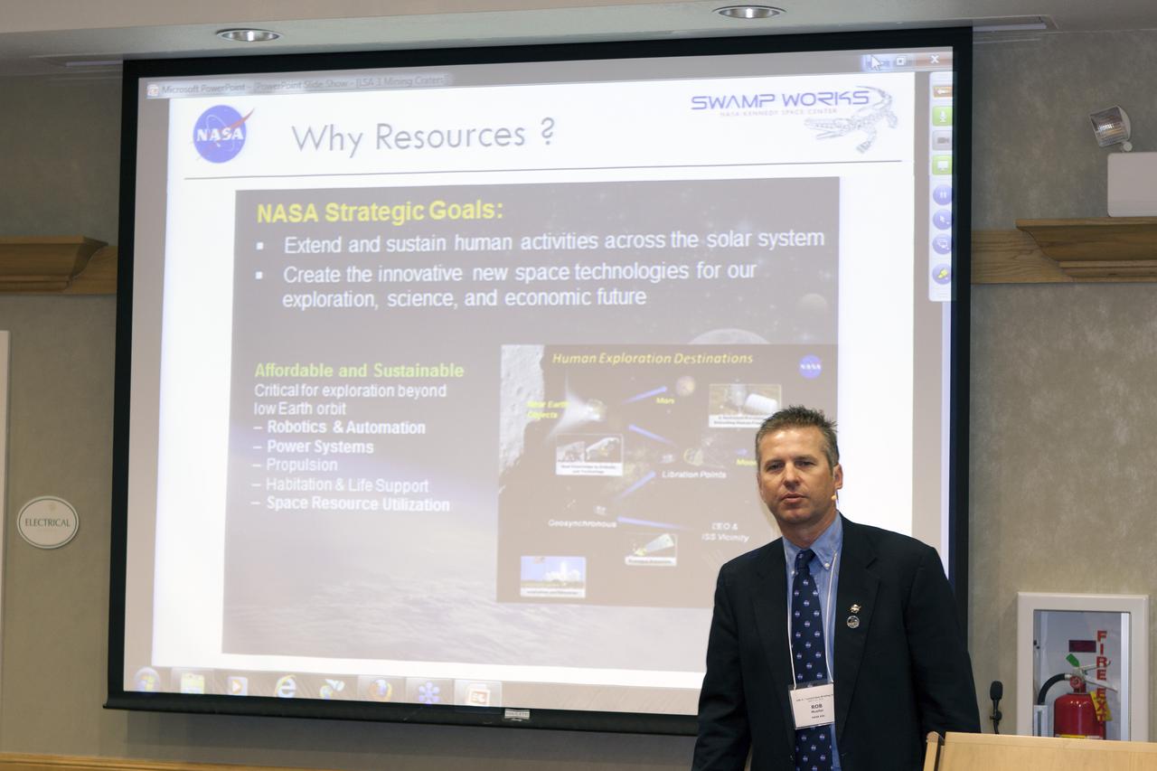
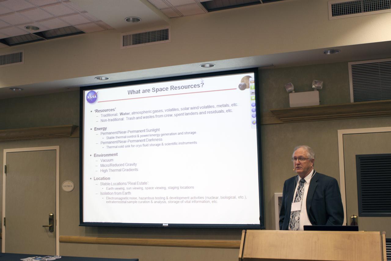
CAPE CANAVERAL, Fla. – At the Courtyard by Marriott hotel in Cocoa Beach, Fla., Rob Mueller, senior technologist in the Surface Systems Office of the Engineering and Technology Directorate at Kennedy Space Center, talks to participants in the room and those participating online during the Third International Workshop on Lunar Superconductor Applications. The workshop included presentations from several engineers and researchers at Kennedy Space Center. The three-day workshop included presentations from speakers throughout the country and focused on Lunar in-situ resource utilization, NASA’s Lunar Ice Prospector called RESOLVE, CubeSats, cryogenic storage and many other topics related to lunar exploration. Photo credit: NASA_Jim Grossmann
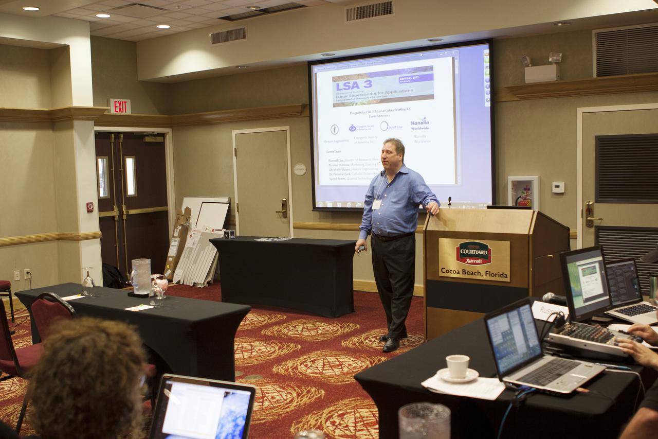
CAPE CANAVERAL, Fla. – At the Courtyard by Marriott hotel in Cocoa Beach, Fla., Russell Cox, director of research with Flexure Engineering, welcomes participants in the room and those participating online to the Third International Workshop on Lunar Superconductor Applications. The workshop included presentations from several engineers and researchers at Kennedy Space Center. The three-day workshop included presentations from speakers throughout the country and focused on Lunar in-situ resource utilization, NASA’s Lunar Ice Prospector called RESOLVE, CubeSats, cryogenic storage and many other topics related to lunar exploration. Photo credit: NASA_Jim Grossmann
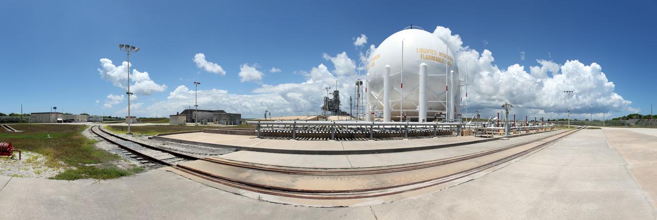
CAPE CANAVERAL, Fla. -- In the Launch Complex 39 area at NASA's Kennedy Space Center in Florida is a liquid hydrogen, or LH2, storage tank. This large ball-shaped, vacuum-jacketed tank is used to store cryogenic propellants for the space shuttle's orange external fuel tank. The LH2 tank is located at the northeast corner of Launch Pad 39A and stores 850,000 gallons of LH2 at a temperature of minus 423 degrees F. The shuttle's external tank is loaded with about 500,000 gallons of LH2 and liquid oxygen, or LOX, about six hours prior to launch in a process known as 'tanking.' Photo credit: NASA_Frankie Martin

CAPE CANAVERAL, Fla. – At the Courtyard by Marriott hotel in Cocoa Beach, Fla., Bonnie Dubrow, business development manager with Flexure Engineering, welcomes participants in the room and those participating online to the Third International Workshop on Lunar Superconductor Applications. The workshop included presentations from several engineers and researchers at Kennedy Space Center. The three-day workshop included presentations from speakers throughout the country and focused on Lunar in-situ resource utilization, NASA’s Lunar Ice Prospector called RESOLVE, CubeSats, cryogenic storage and many other topics related to lunar exploration. Photo credit: NASA_Jim Grossmann

KENNEDY SPACE CENTER, Fla. -- A long view of Launch Complex 39 is caught by the early morning sun. Left of center is Launch Pad 39A with Space Shuttle Discovery. At its left is the 300,000-gallon water tank that is part of the sound suppression system. Hoses from the tank can be seen coiling under the pad, next to the opening of the flame trench, part of the flame detector system. In the foreground is a retention pond; another is at right center. At far right, the ball-shaped structure is a 850,000-gallon storage tank for the cryogenic liquid oxygen, one of the propellants of the orbiter’s main engines. On the horizon can be seen the 525-foot tall Vehicle Assembly Building
These photos show how teams at NASA’s Marshall Space Flight Center in Huntsville, Alabama, are testing an innovative approach to achieve zero boiloff storage of liquid hydrogen using two stages of active cooling, which could prevent the loss of valuable propellant during future long-duration spaceflight missions. Test teams installed the propellant tank in Test Stand 300 at NASA Marshall in early June, and the 90-day test campaign is scheduled to conclude in September. The tank is wrapped in a multi-layer insulation blanket that includes a thin aluminum heat shield fitted between layers. A second set of tubes, carrying helium at about minus 298 Fahrenheit, is integrated into the shield. This intermediate cooling layer intercepts and rejects incoming heat before it reaching the tank, easing the heat load on the tube-on-tank system. The Cryogenic Fluid Management Portfolio Project is a cross-agency team based at NASA Marshall and the agency’s Glenn Research Center in Cleveland. The cryogenic portfolio’s work is under NASA’s Technology Demonstration Missions Program, part of NASA’s Space Technology Mission Directorate, and is comprised of more than 20 individual technology development activities. For more information, contact NASA Marshall’s Office of Communications at 256-544-0034.
The control panel that will direct and control the flow of liquid oxygen, referred to as a skid, is photographed at Launch Pad 39B on Nov. 8, 2019, at NASA’s Kennedy Space Center in Florida. The agency’s Exploration Ground Systems oversaw testing of the pad’s cryogenic systems – the infrastructure that will support the flow of liquid hydrogen and liquid oxygen from the storage tanks, located near the pad, to the Space Launch System (SLS) rocket – in preparation for the launch of SLS with the Orion spacecraft atop for the uncrewed Artemis I mission. Each of the liquid oxygen and liquid hydrogen tanks can hold more than 800,000 gallons of propellant. The liquid oxygen will require the use of pumps to push it from the tank to the rocket, while the lighter liquid hydrogen will make its way up to the pad using gaseous hydrogen to pressurize the sphere.
The control panel that will direct and control the flow of liquid oxygen, referred to as a skid, is photographed at Launch Pad 39B on Nov. 8, 2019, at NASA’s Kennedy Space Center in Florida. The agency’s Exploration Ground Systems oversaw testing of the pad’s cryogenic systems – the infrastructure that will support the flow of liquid hydrogen and liquid oxygen from the storage tanks, located near the pad, to the Space Launch System (SLS) rocket – in preparation for the launch of SLS with the Orion spacecraft atop for the uncrewed Artemis I mission. Each of the liquid oxygen and liquid hydrogen tanks can hold more than 800,000 gallons of propellant. The liquid oxygen will require the use of pumps to push it from the tank to the rocket, while the lighter liquid hydrogen will make its way up to the pad using gaseous hydrogen to pressurize the sphere.
CAPE CANAVERAL, Fla. – Inside the Space Station Processing Facility at NASA’s Kennedy Space Center in Florida, a cold storage team member prepares an International Space Station experiment cryogenic freezer called a Glacier unit, for transport to Space Launch Complex-40 at Cape Canaveral Air Force Station. The unit is for an experiment late-load demonstration test with the Space Exploration Technologies Corp. SpaceX Falcon 9 rocket and Dragon capsule. SpaceX is one of two companies under contract with NASA to take cargo to the International Space Station. NASA is working with SpaceX to combine its last two demonstration flights, and if approved, the Falcon 9 would launch the Dragon capsule to the orbiting laboratory for a docking within the next several months. Photo credit: NASA/Amanda Diller
In this view, liquid oxygen lines can be seen going up the mobile launcher at Launch Pad 39B on Nov. 8, 2019, at NASA’s Kennedy Space Center in Florida. The agency’s Exploration Ground Systems oversaw testing of the pad’s cryogenic systems – the infrastructure that will support the flow of liquid hydrogen and liquid oxygen from the storage tanks, located near the pad, to the Space Launch System (SLS) rocket – in preparation for the launch of SLS with the Orion spacecraft atop for the uncrewed Artemis I mission. Each of the liquid oxygen and liquid hydrogen tanks can hold more than 800,000 gallons of propellant. The liquid oxygen will require the use of pumps to push it from the tank to the rocket, while the lighter liquid hydrogen will make its way up to the pad using gaseous hydrogen to pressurize the sphere.
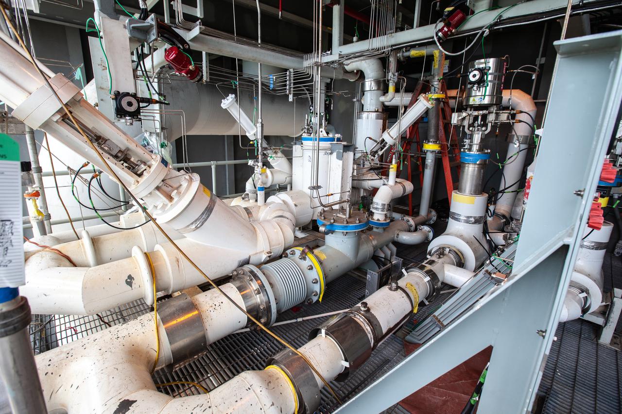
The control panel that will direct and control the flow of liquid oxygen and liquid oxygen, referred to as a skid, is photographed at Launch Pad 39B on Nov. 8, 2019, at NASA’s Kennedy Space Center in Florida. The agency’s Exploration Ground Systems oversaw testing of the pad’s cryogenic systems – the infrastructure that will send the liquid hydrogen and liquid oxygen from the storage tanks to the Space Launch System (SLS) rocket – in preparation for the launch of SLS with the Orion spacecraft atop for the uncrewed Artemis I mission. Each of the liquid oxygen and liquid hydrogen tanks can hold more than 800,000 gallons of propellant. The liquid oxygen will require the use of pumps to push it from the tank to the rocket, while the lighter liquid hydrogen will make its way up to the pad using gaseous hydrogen to pressurize the sphere.
The Tail Service Mast Umbilicals that will connect to NASA’s Space Launch System (SLS) rocket, containing fluid lines for liquid oxygen and liquid hydrogen propellant loading, are photographed on the mobile launcher at Launch Pad 39B on Nov. 8, 2019, at the agency’s Kennedy Space Center in Florida. NASA’s Exploration Ground Systems oversaw testing of the pad’s cryogenic systems – the infrastructure that will support the flow of liquid hydrogen and liquid oxygen from the storage tanks to the rocket – in preparation for the launch of SLS with the Orion spacecraft atop for the uncrewed Artemis I mission. Each of the liquid oxygen and liquid hydrogen tanks can hold more than 800,000 gallons of propellant. The liquid oxygen will require the use of pumps to push it from the tank to the rocket, while the lighter liquid hydrogen will make its way up to the pad using gaseous hydrogen to pressurize the sphere.
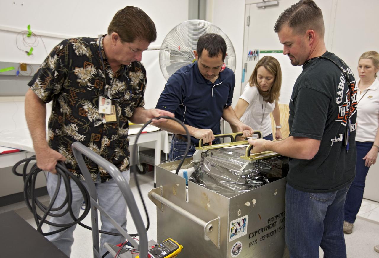
CAPE CANAVERAL, Fla. – Inside the Space Station Processing Facility at NASA’s Kennedy Space Center in Florida, cold storage team members pack an International Space Station experiment cryogenic freezer called a Glacier unit, for transport to Space Launch Complex-40 at Cape Canaveral Air Force Station. The unit is for an experiment late-load demonstration test with the Space Exploration Technologies Corp. SpaceX Falcon 9 rocket and Dragon capsule. SpaceX is one of two companies under contract with NASA to take cargo to the International Space Station. NASA is working with SpaceX to combine its last two demonstration flights, and if approved, the Falcon 9 would launch the Dragon capsule to the orbiting laboratory for a docking within the next several months. Photo credit: NASA/Amanda Diller
CAPE CANAVERAL, Fla. –Inside the Space Station Processing Facility at NASA’s Kennedy Space Center in Florida, a cold storage team member prepares an International Space Station experiment cryogenic freezer called a Glacier unit, for transport to Space Launch Complex-40 at Cape Canaveral Air Force Station. The unit is for an experiment late-load demonstration test with the Space Exploration Technologies Corp. SpaceX Falcon 9 rocket and Dragon capsule. SpaceX is one of two companies under contract with NASA to take cargo to the International Space Station. NASA is working with SpaceX to combine its last two demonstration flights, and if approved, the Falcon 9 would launch the Dragon capsule to the orbiting laboratory for a docking within the next several months. Photo credit: NASA/Amanda Diller
CAPE CANAVERAL, Fla. – Inside the Space Station Processing Facility at NASA’s Kennedy Space Center in Florida, cold storage team members cart an International Space Station experiment cryogenic freezer called a Glacier unit, for transport to Space Launch Complex-40 at Cape Canaveral Air Force Station. The unit is for an experiment late-load demonstration test with Space Exploration Technologies Corp. SpaceX Falcon 9 rocket and Dragon capsule. SpaceX is one of two companies under contract with NASA to take cargo to the International Space Station. NASA is working with SpaceX to combine its last two demonstration flights, and if approved, the Falcon 9 would launch the Dragon capsule to the orbiting laboratory for a docking within the next several months. Photo credit: NASA/Amanda Diller
Technicians at work in the Materials Processing Laboratory’s Creep Facility at the National Aeronautics and Space Administration (NASA) Lewis Research Center. The technicians supported the engineers’ studies of refractory materials, metals, and advanced superalloys. The Materials Processing Laboratory contained laboratories and test areas equipped to prepare and develop these metals and materials. The ultra-high vacuum lab, seen in this photograph, contained creep and tensile test equipment. Creep testing is used to study a material’s ability to withstand long durations under constant pressure and temperatures. The equipment measured the strain over a long period of time. Tensile test equipment subjects the test material to strain until the material fails. The two tests were used to determine the strength and durability of different materials. The Materials Processing Laboratory also housed arc and electron beam melting furnaces, a hydraulic vertical extrusion press, compaction and forging equipment, and rolling mills and swagers. There were cryogenic and gas storage facilities and mechanical and oil diffusion vacuum pumps. The facility contained both instrumental and analytical chemistry laboratories for work on radioactive or toxic materials and the only shop to machine toxic materials in the Midwest.
Operation of the High Energy Rocket Engine Research Facility (B-1), left, and Nuclear Rocket Dynamics and Control Facility (B-3) at the National Aeronautics and Space Administration’s (NASA) Plum Brook Station in Sandusky, Ohio. The test stands were constructed in the early 1960s to test full-scale liquid hydrogen fuel systems in simulated altitude conditions. Over the next decade each stand was used for two major series of liquid hydrogen rocket tests: the Nuclear Engine for Rocket Vehicle Application (NERVA) and the Centaur second-stage rocket program. The different components of these rocket engines could be studied under flight conditions and adjusted without having to fire the engine. Once the preliminary studies were complete, the entire engine could be fired in larger facilities. The test stands were vertical towers with cryogenic fuel and steam ejector systems. B-1 was 135 feet tall, and B-3 was 210 feet tall. Each test stand had several levels, a test section, and ground floor shop areas. The test stands relied on an array of support buildings to conduct their tests, including a control building, steam exhaust system, and fuel storage and pumping facilities. A large steam-powered altitude exhaust system reduced the pressure at the exhaust nozzle exit of each test stand. This allowed B-1 and B-3 to test turbopump performance in conditions that matched the altitudes of space.