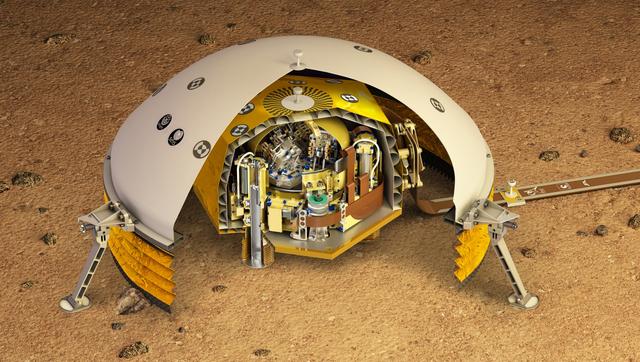
This artist's rendering shows a cutaway of the Seismic Experiment for Interior Structure instrument, or SEIS, which will fly as part of NASA's Mars InSight lander. SEIS is a highly sensitive seismometer that will be used to detect marsquakes from the Red Planet's surface for the first time. There are two layers in this cutaway. The outer layer is the Wind and Thermal Shield -- a covering that protects the seismometer from the Martian environment. The wind on Mars, as well as extreme temperature changes, could affect the highly sensitive instrument. The inside layer is SEIS itself, a brass-colored dome that houses the instrument's three pendulums. These insides are inside a titanium vacuum chamber to further isolate them from temperature changes on the Martian surface. https://photojournal.jpl.nasa.gov/catalog/PIA22320
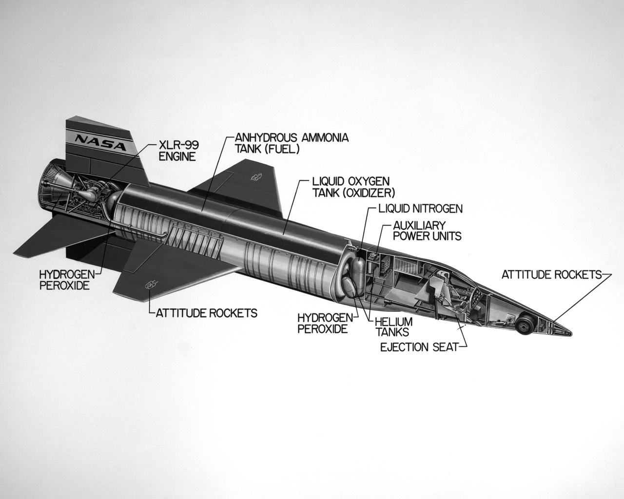
Cutaway drawing of the North American X-15.
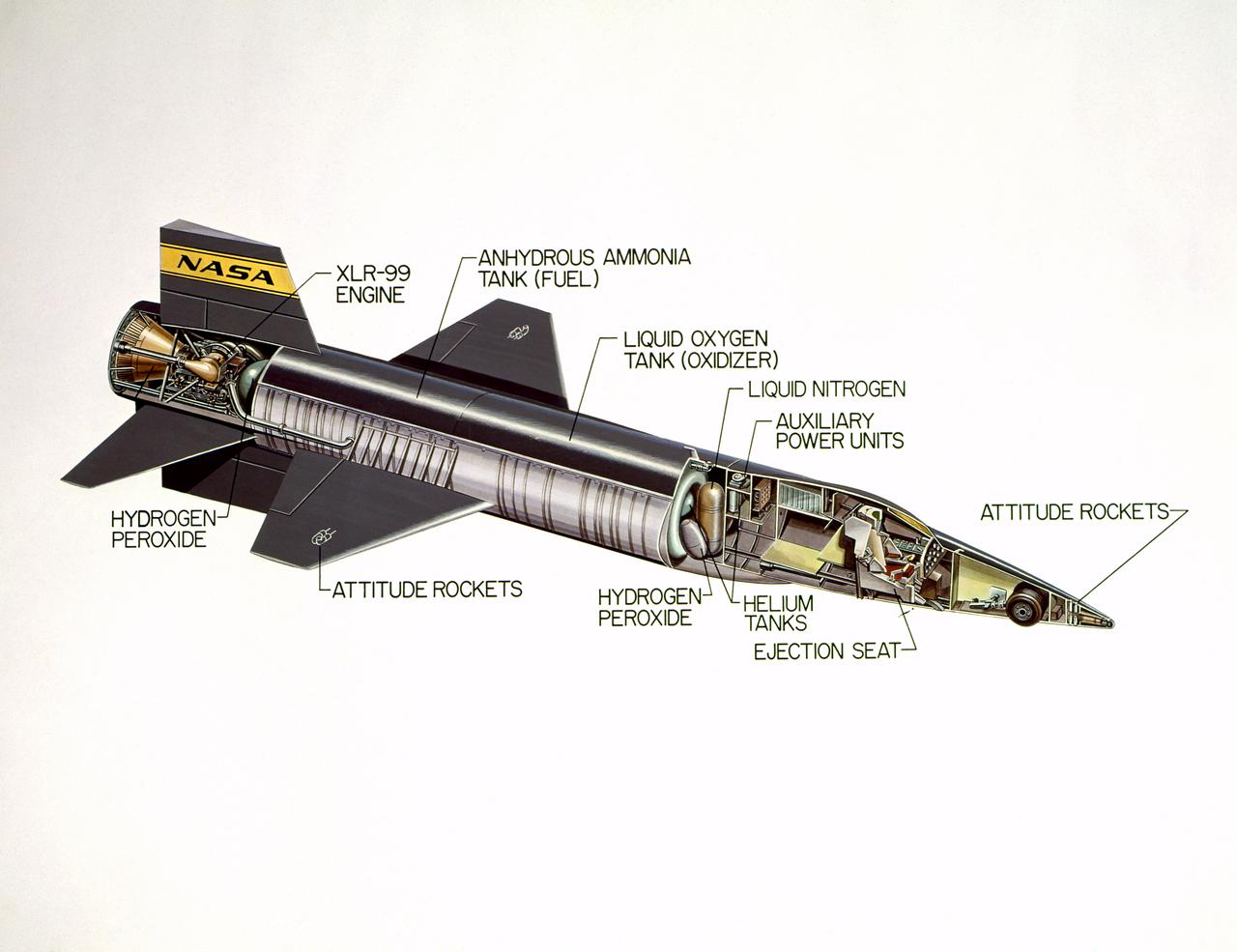
Cutaway drawing of the North American X-15.
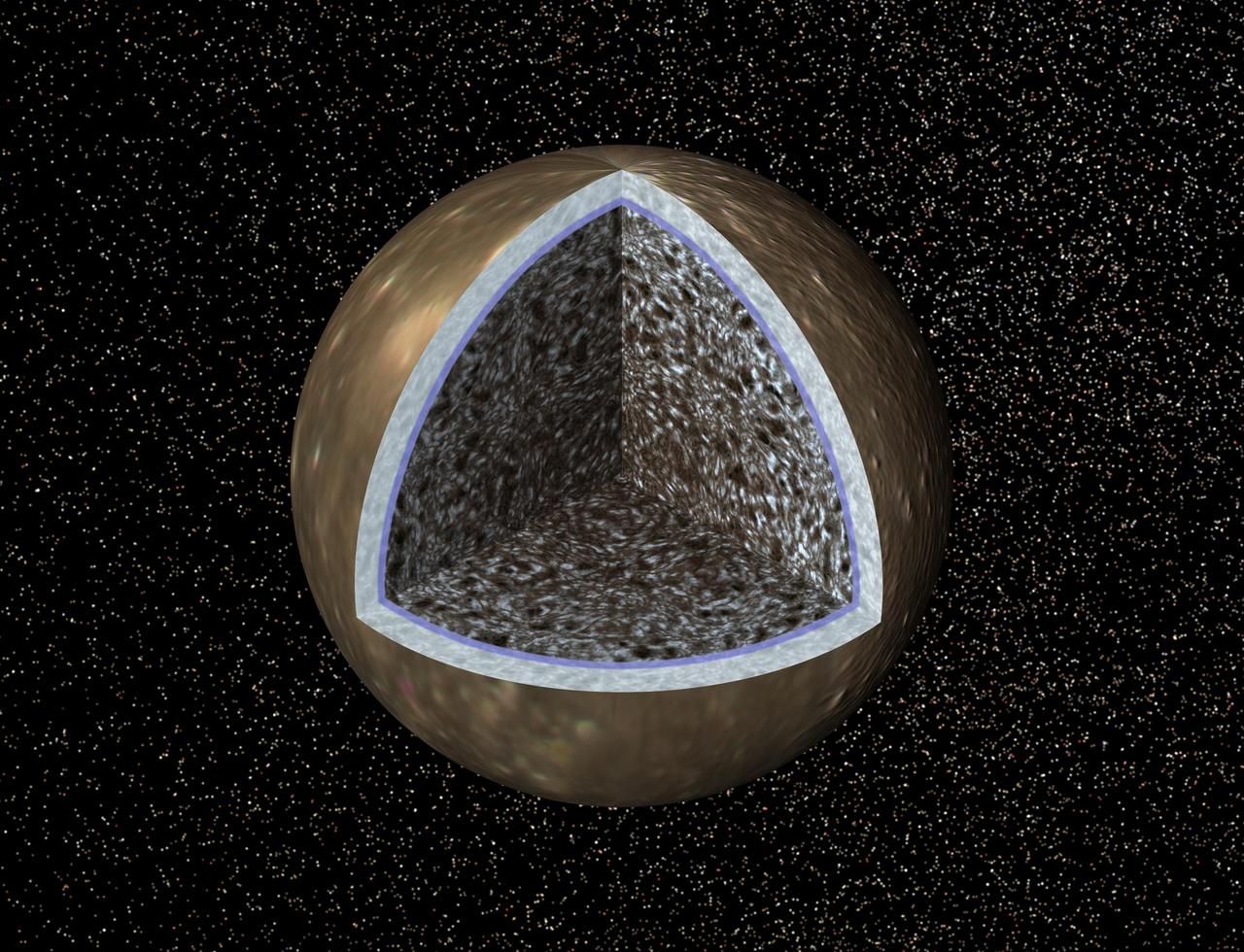
This artist concept, a cutaway view of Jupiter moon Callisto, is based on recent data from NASA Galileo spacecraft which indicates a salty ocean may lie beneath Callisto icy crust.
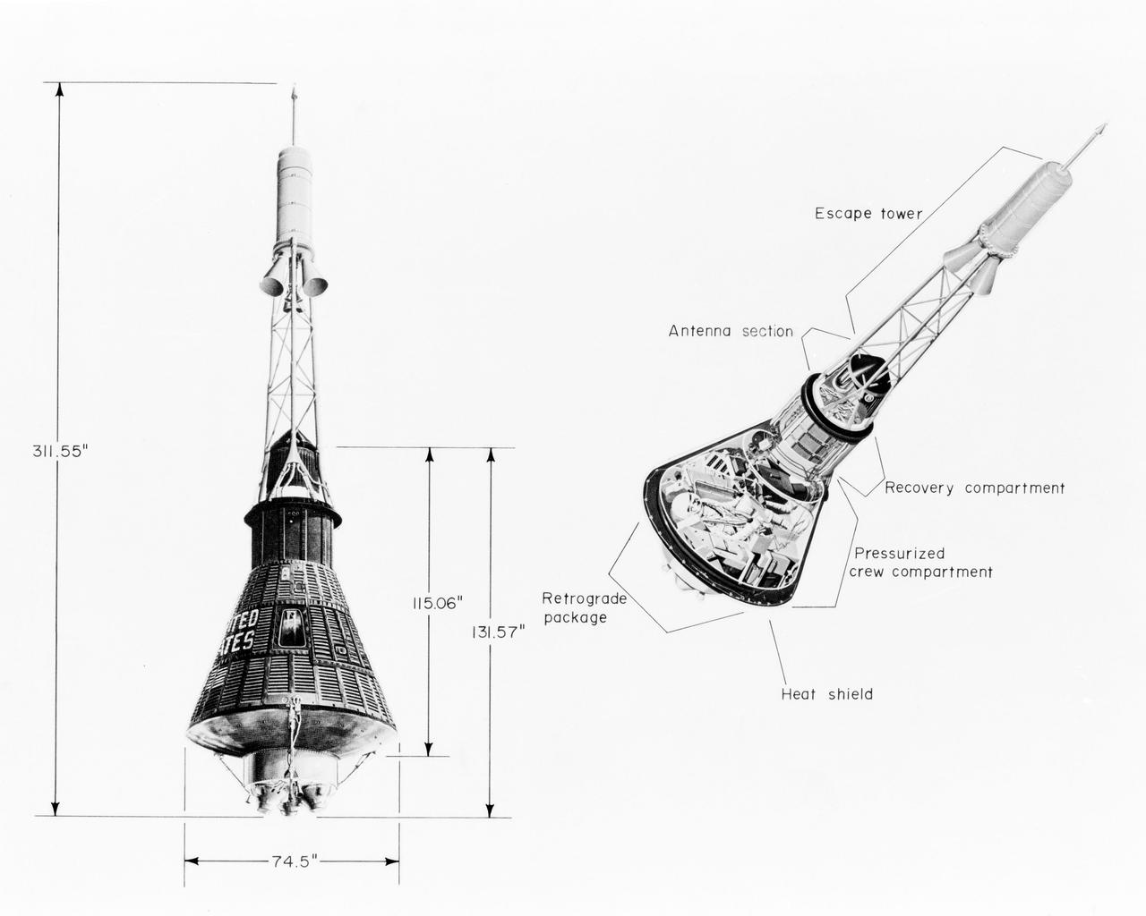
S63-18867 (October 1963) --- Mercury spacecraft with measurements and cutaway view. Photo credit: NASA
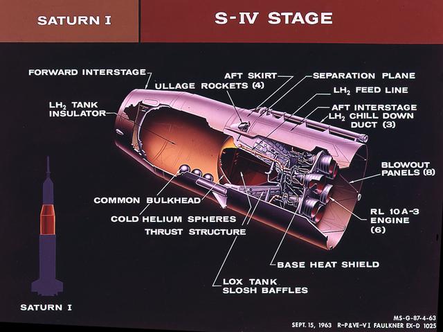
This cutaway of the Saturn I S-IV stage (second stage) illustrates the booster's components. Powered by six RL-10 engines, the S-IV stage was capable of producing 90,000 pounds of thrust. Development of the Saturn S-IV stage by the Marshall Space Flight Center (MSFC) contributed many technological breakthroughs vital to the success of the Apollo lunar program, including the use of liquid hydrogen as a propellant.
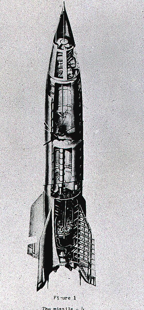
The cutaway drawing of the A-4 (Aggregate-4) rocket. Later renamed the V-2 (Vengeance Weapon-2), The rocket was developed by Dr. Wernher von Braun and the German rocket team at Peenemuende, Germany on the Baltic Sea. At the end of World War II, the team of German engineers and scientists came to the United States and continued rocket research for the Army at Fort Bliss, Texas, and Redstone Arsenal in Huntsville, Alabama.
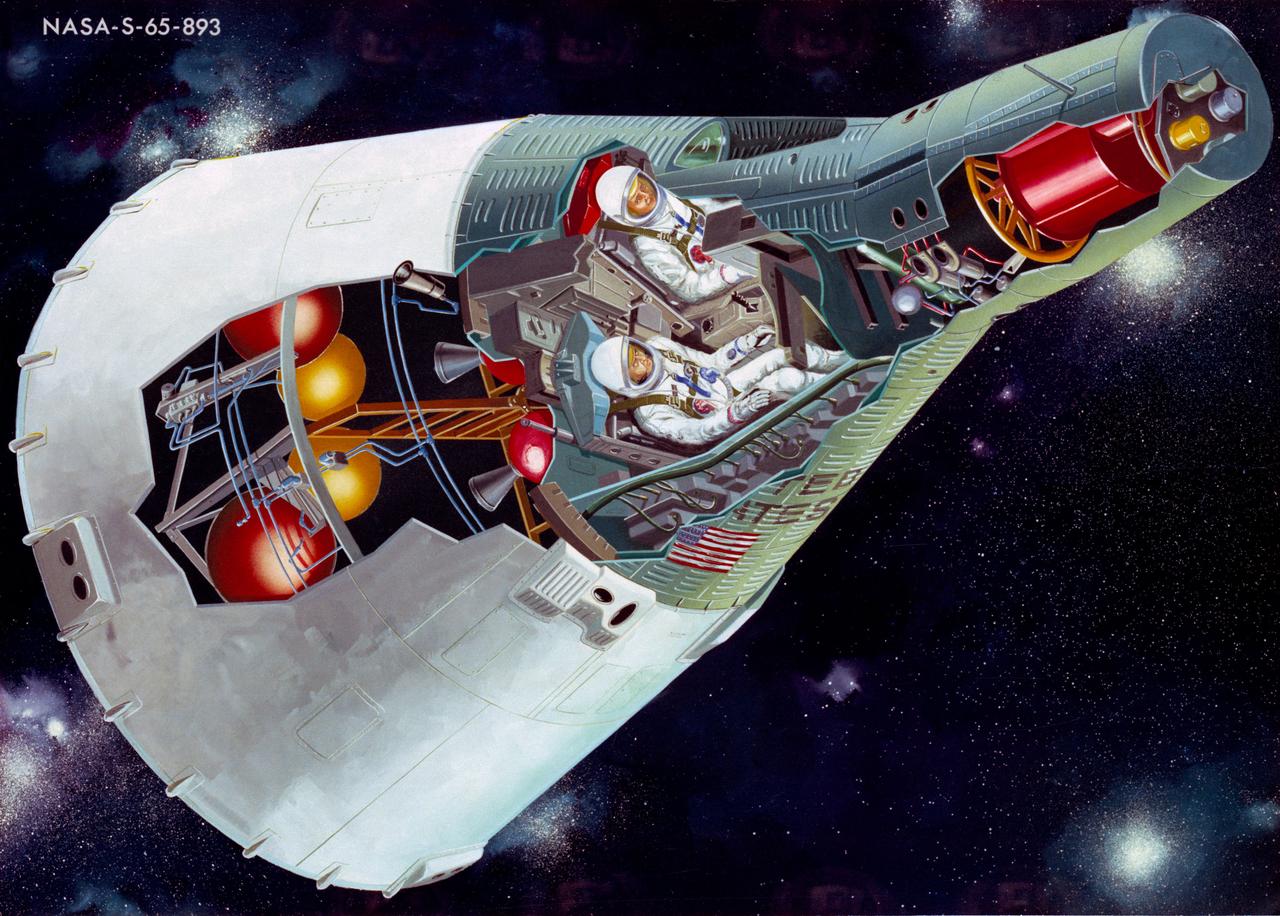
S65-14257 (January 1965) --- This is an artist's concept of a two-man Gemini spacecraft in flight, showing a cutaway view.
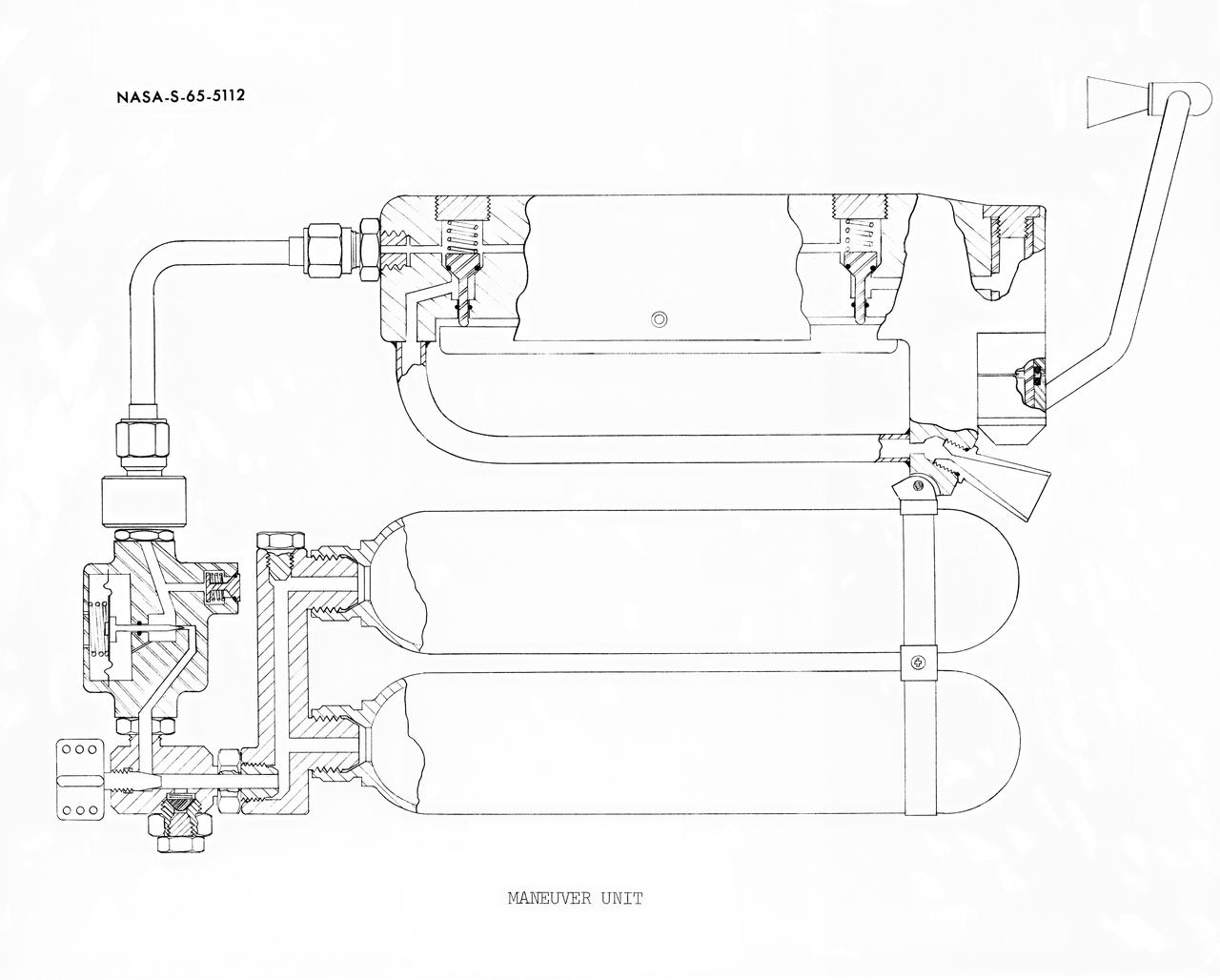
S65-05112 (30 May 1965) --- Cutaway engineering drawing showing some of the features of the zero-gravity integral propulsion unit.
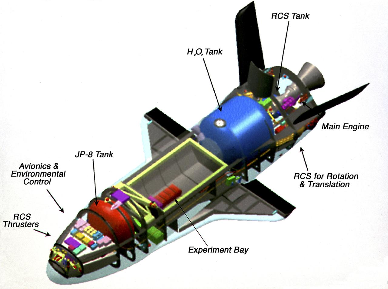
This photograph is an artist's cutaway view of the X-37 flight demonstrator showing its components. The X-37 experimental launch vehicle is roughly 27.5 feet (8.3 meters) long and 15 feet (4.5 meters) in wingspan. Its experiment bay is 7 feet (2.1 meters) long and 4 feet (1.2 meters) in diameter. Designed to operate in both the orbital and reentry phases of flight, the X-37 will increase both safety and reliability, while reducing launch costs from $10,000 per pound to $1000 per pound. The X-37 can be carried into orbit by the Space Shuttle or be launched by an expendable rocket. Managed by Marshall Space Flight Center and built by the Boeing Company, the X-37 is scheduled to fly two orbital missions in 2002/2003 to test the reusable launch vehicle technologies.

Peering into the thousands of frozen layers inside Greenland’s ice sheet is like looking back in time. Each layer provides a record of what Earth’s climate was like at the dawn of civilization, or during the last ice age, or during an ancient period of warmth similar to the one we experience today. Scientists using ice-penetrating radar data collected by NASA’s Operation IceBridge and earlier airborne campaigns have built the first-ever comprehensive map of layers deep inside the Greenland Ice Sheet. View the full video: <a href="http://youtu.be/u0VbPE0TOtQ" rel="nofollow">youtu.be/u0VbPE0TOtQ</a> Credit: NASA’s Goddard Space Flight Center <b><a href="http://www.nasa.gov/audience/formedia/features/MP_Photo_Guidelines.html" rel="nofollow">NASA image use policy.</a></b> <b><a href="http://www.nasa.gov/centers/goddard/home/index.html" rel="nofollow">NASA Goddard Space Flight Center</a></b> enables NASA’s mission through four scientific endeavors: Earth Science, Heliophysics, Solar System Exploration, and Astrophysics. Goddard plays a leading role in NASA’s accomplishments by contributing compelling scientific knowledge to advance the Agency’s mission. <b>Follow us on <a href="http://twitter.com/NASAGoddardPix" rel="nofollow">Twitter</a></b> <b>Like us on <a href="http://www.facebook.com/pages/Greenbelt-MD/NASA-Goddard/395013845897?ref=tsd" rel="nofollow">Facebook</a></b> <b>Find us on <a href="http://instagram.com/nasagoddard?vm=grid" rel="nofollow">Instagram</a></b>
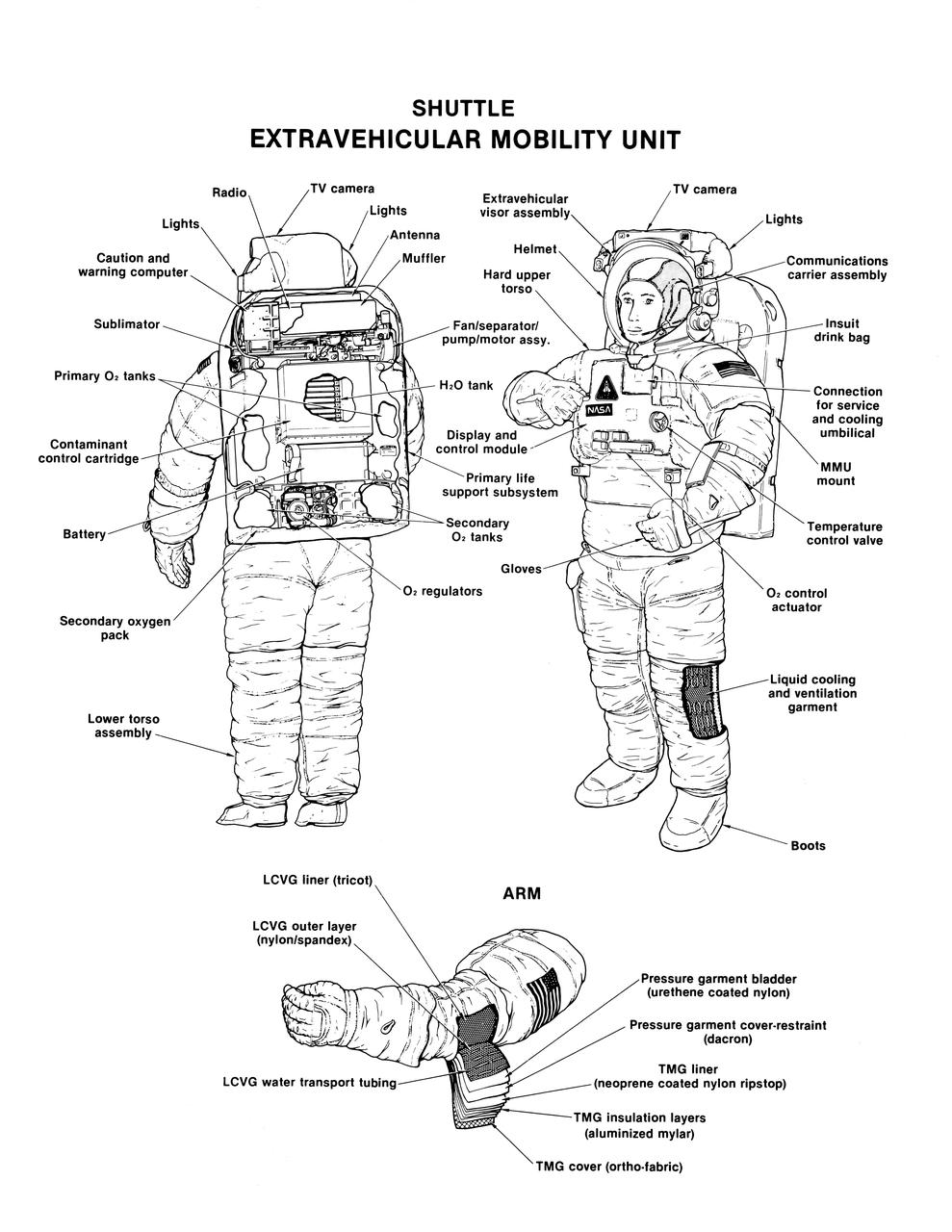
Labeled cutaway line drawing of the Shuttle extravehicular mobility unit (EMU) identifies its various components and equipment. The portable life support system (PLSS) and protective layers of fabric (thermal micrometeoroid garment (TMG)) incorporated in this extravehicular activity (EVA) space suit are shown.
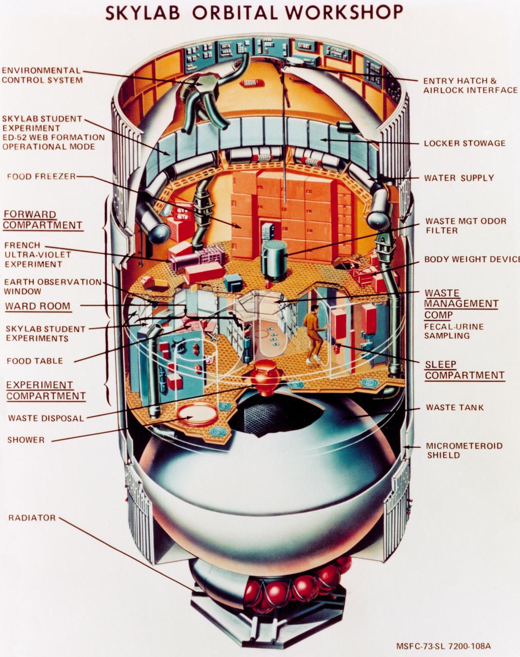
S73-23919 (May 1973) --- An artist's concept illustrating a cutaway view of the Skylab 1 Orbital Workshop (OWS). The OWS is one of the five major components of the Skylab 1 space station cluster which was launched by a Saturn V on May 14, 1973 into Earth orbit. Photo credit: NASA
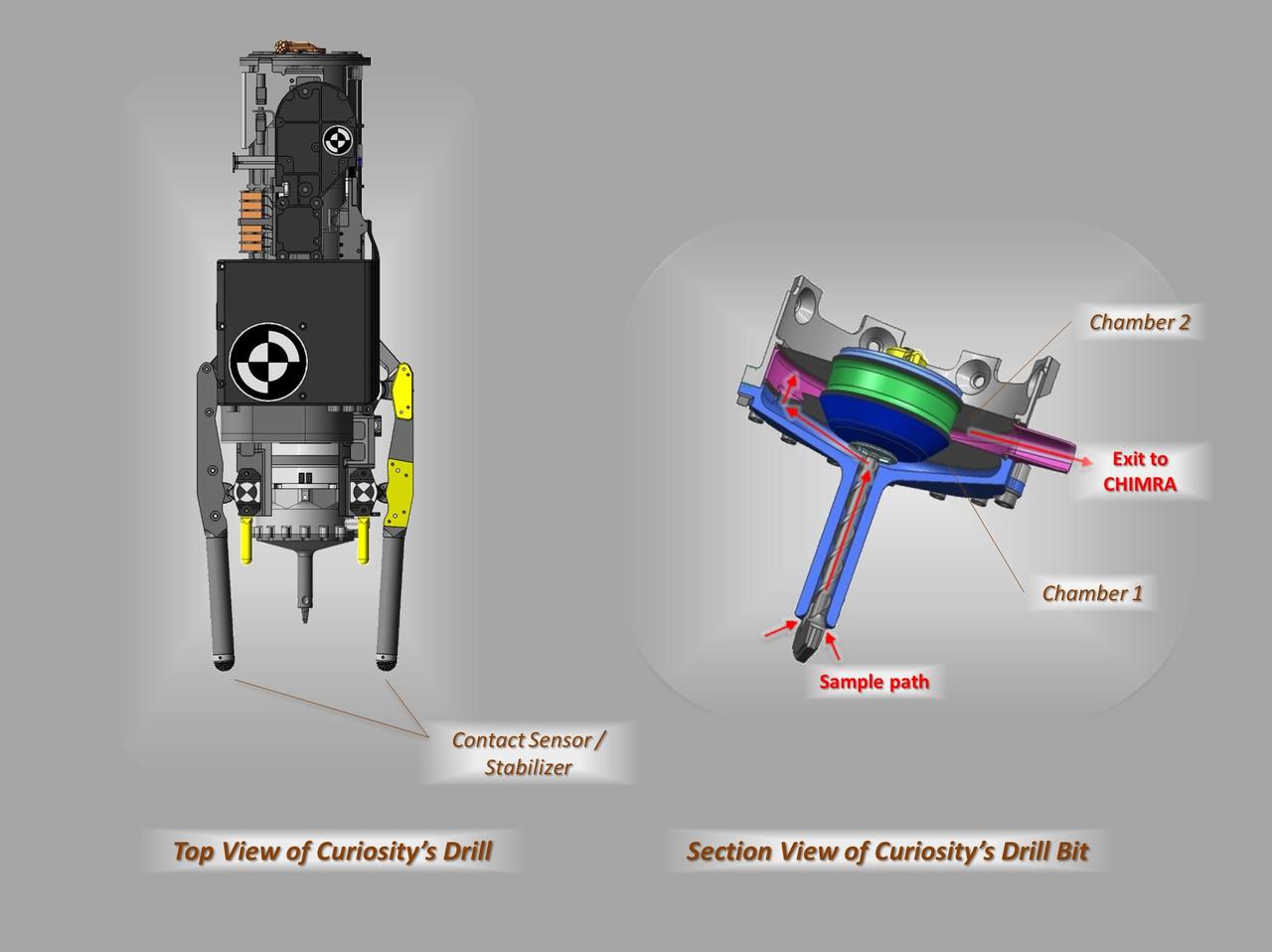
These schematic drawings show a top view and a cutaway view of a section of the drill on NASA Curiosity rover on Mars.
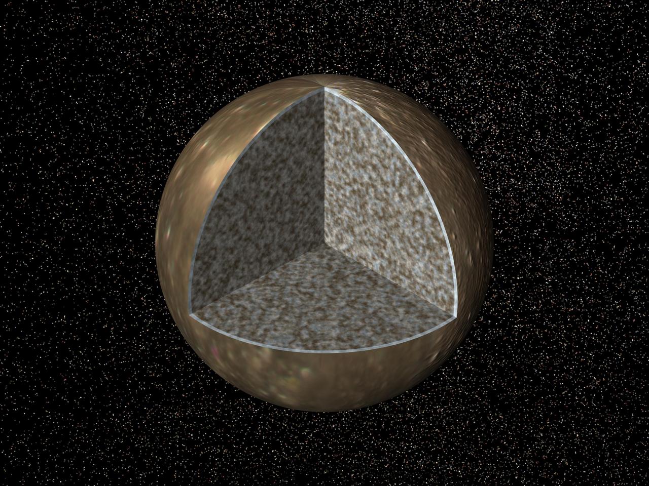
Cutaway view of the possible internal structure of Callisto. The surface of the satellite is a mosaic of images obtained in 1979 by NASA Voyager spacecraft.
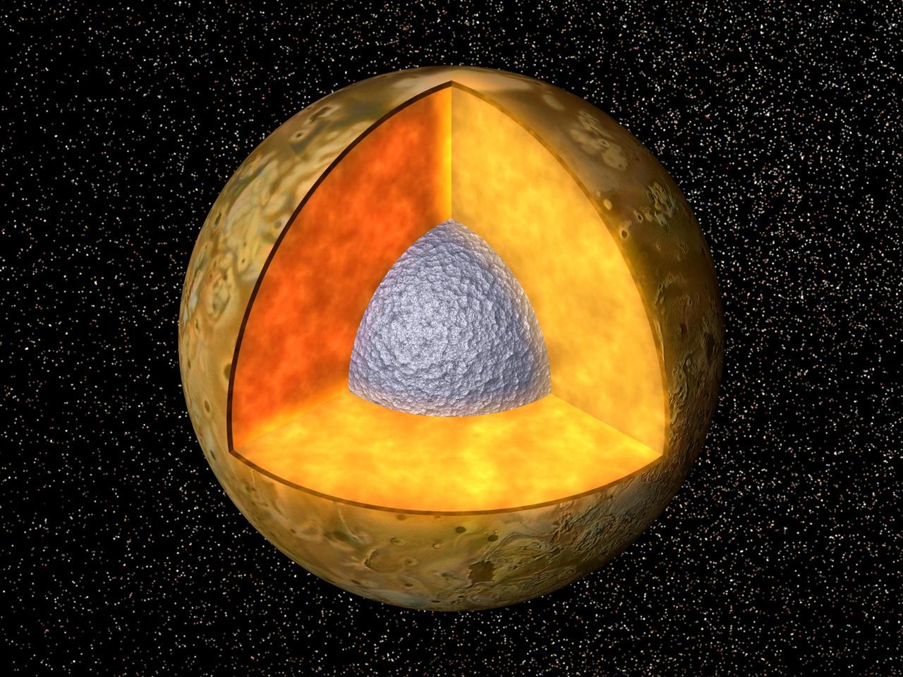
Cutaway view of the possible internal structure of Io. The surface of the satellite is a mosaic of images obtained in 1979 by NASA Voyager spacecraft.
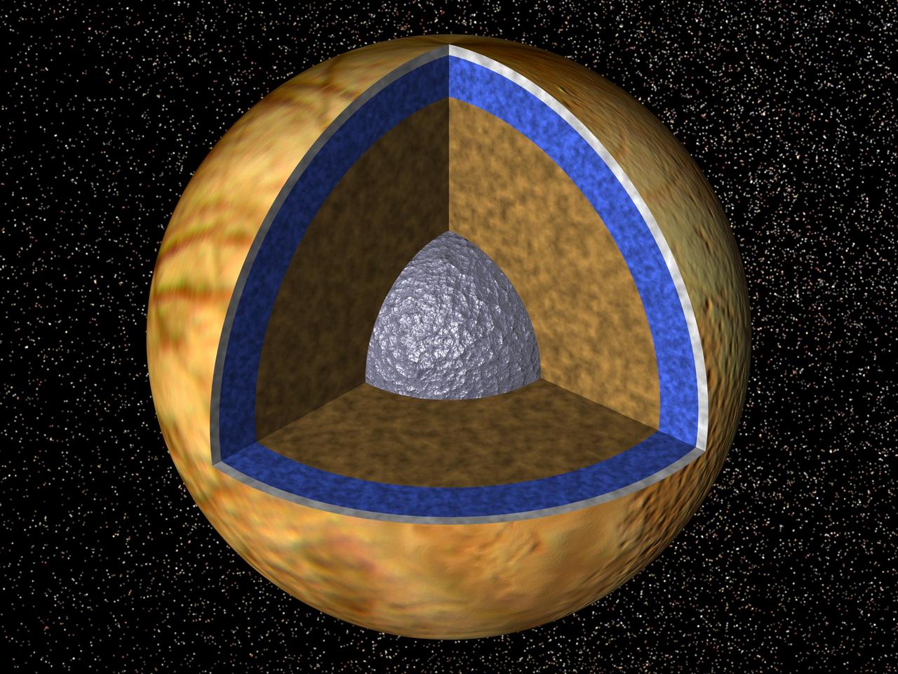
Cutaway view of the possible internal structure of Europa. The surface of the satellite is a mosaic of images obtained in 1979 by NASA Voyager spacecraft.
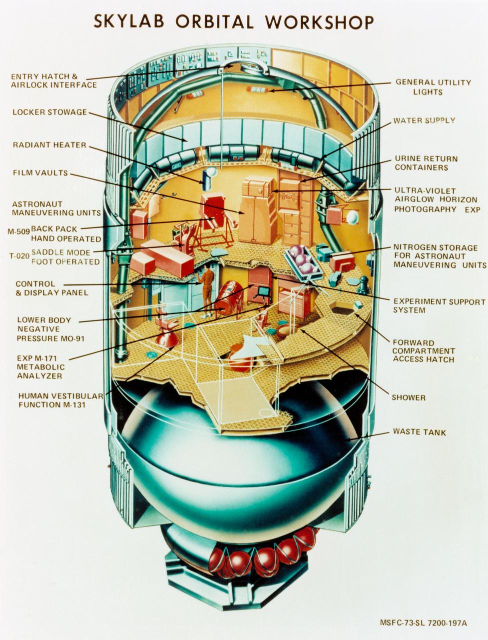
S73-23918 (May 1973) --- An artist's concept illustrating a cutaway view of the Skylab 1 Orbital Workshop (OWS). The OWS is one of the five major components of the Skylab 1 space station cluster which was launched by a Saturn V on May 14, 1973 into Earth orbit. Photo credit: NASA
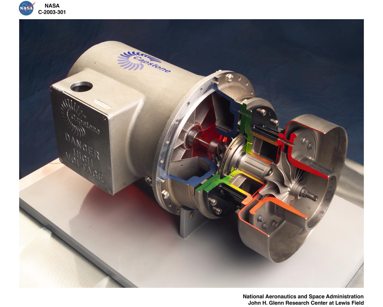
DEMONSTRATION RIGS - CAPSTONE MICROTURBINE CUTAWAY
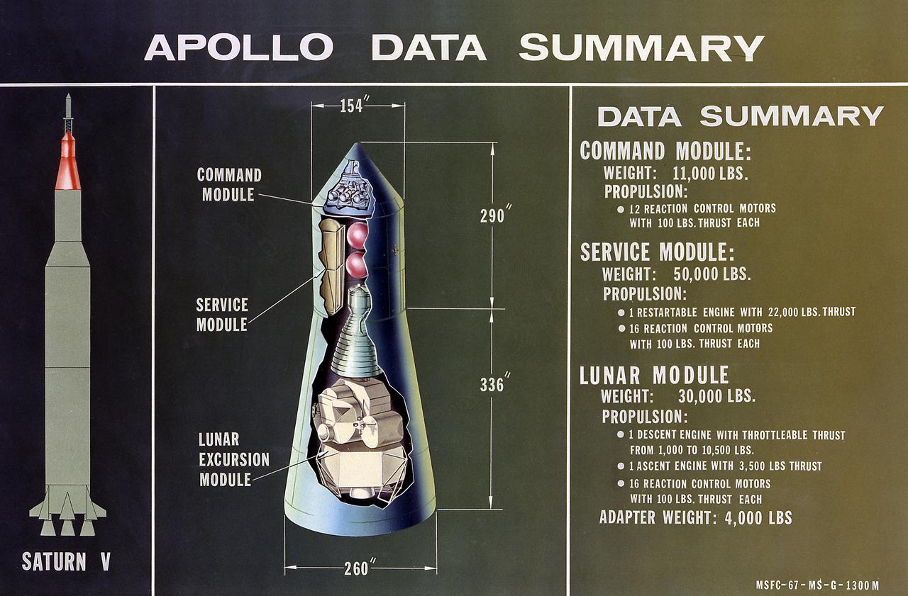
This is a cutaway illustration of the Apollo Spacecraft configuration and data summary.
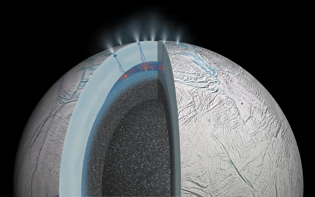
This cutaway view of Saturn moon Enceladus is an artist rendering that depicts possible hydrothermal activity that may be taking place on and under the seafloor of the moon subsurface ocean, based on published results from NASA Cassini mission.
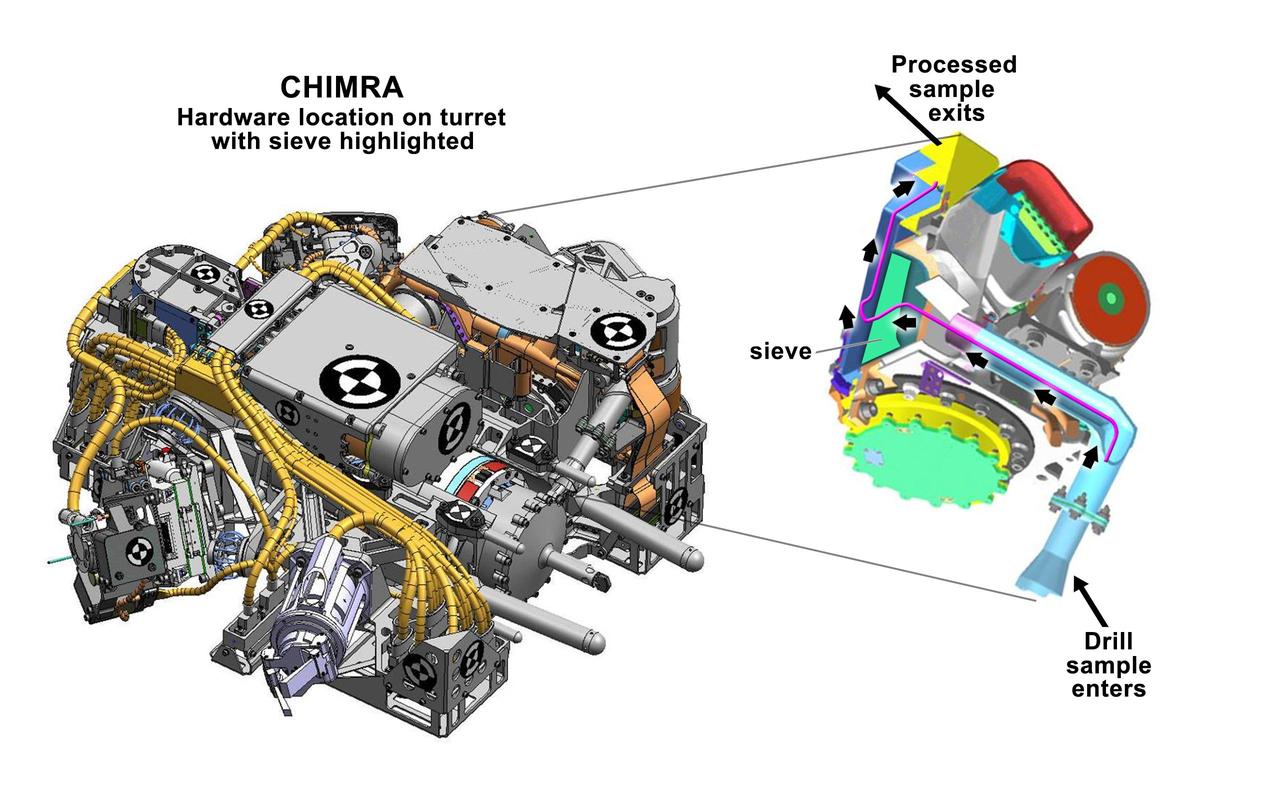
This figure shows the location of CHIMRA on the turret of NASA Curiosity rover, together with a cutaway view of the device. CHIMRA processes samples from the rover scoop or drill and delivers them to science instruments.
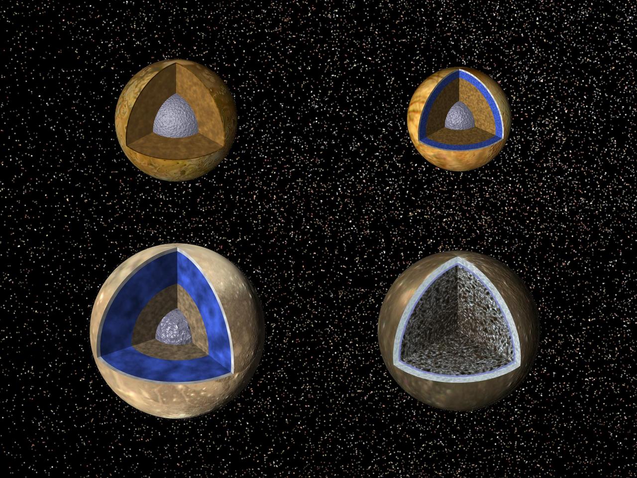
Cutaway views of the possible internal structures of the Galilean satellites. Ganymede at lower left, Callisto at lower right, Io on upper left, and Europa on upper right in a combined biew from NASA Galileo and Voyager spacecraft.
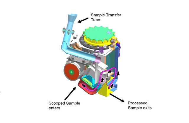
This cutaway view shows the internal chambers of the Collection and Handling for In-Situ Martian Rock Analysis CHIMRA device, attached to the turret at the end of the robotic arm on NASA Curiosity Mars rover.
Artwork - cutaway HAZMAT tank - depicts interior/exterior deployment activities
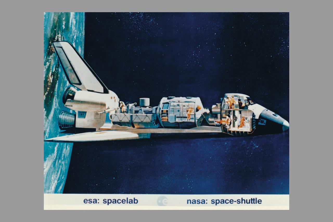
Space Shuttle cutaway showing astronauts working with ESA Spacelab
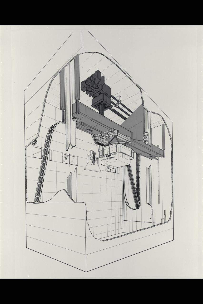
Illustration Vertical Motion Simulator (VMS) Facility and Cab cutaway
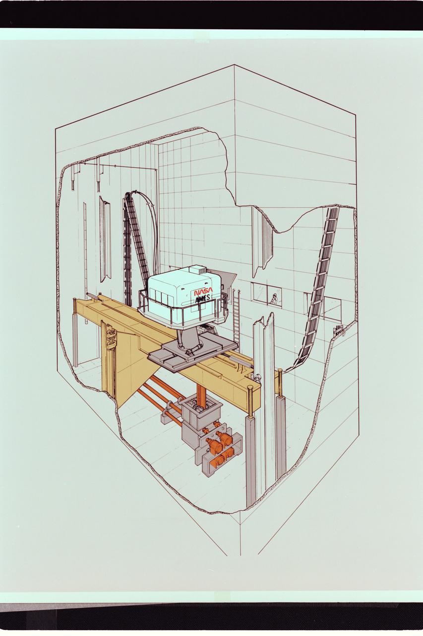
Artwork: cutaway N-243 Vertical Motion Simulator (VMS)
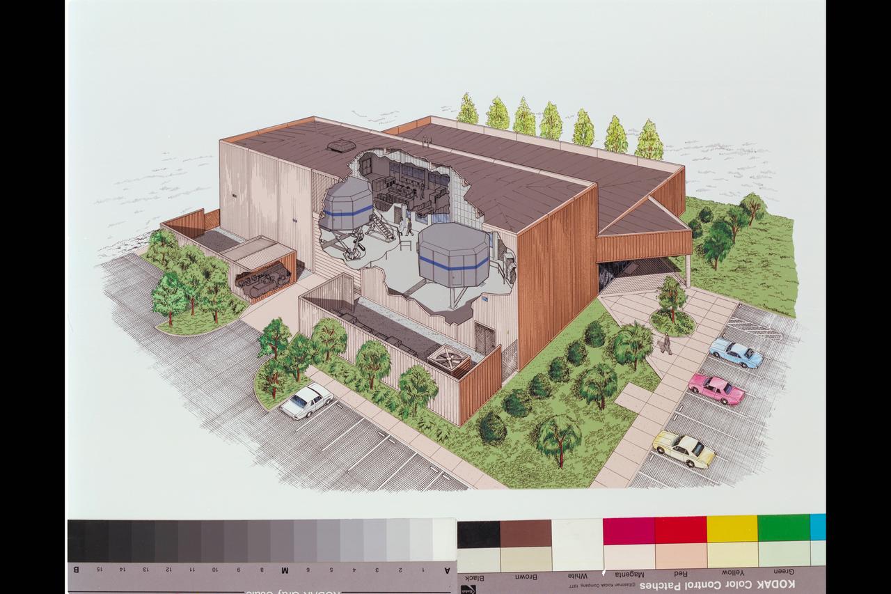
Cutaway Artwork MVSRF - Man Vehicle Systems Research facility N-257 (named changed to CVSRF)
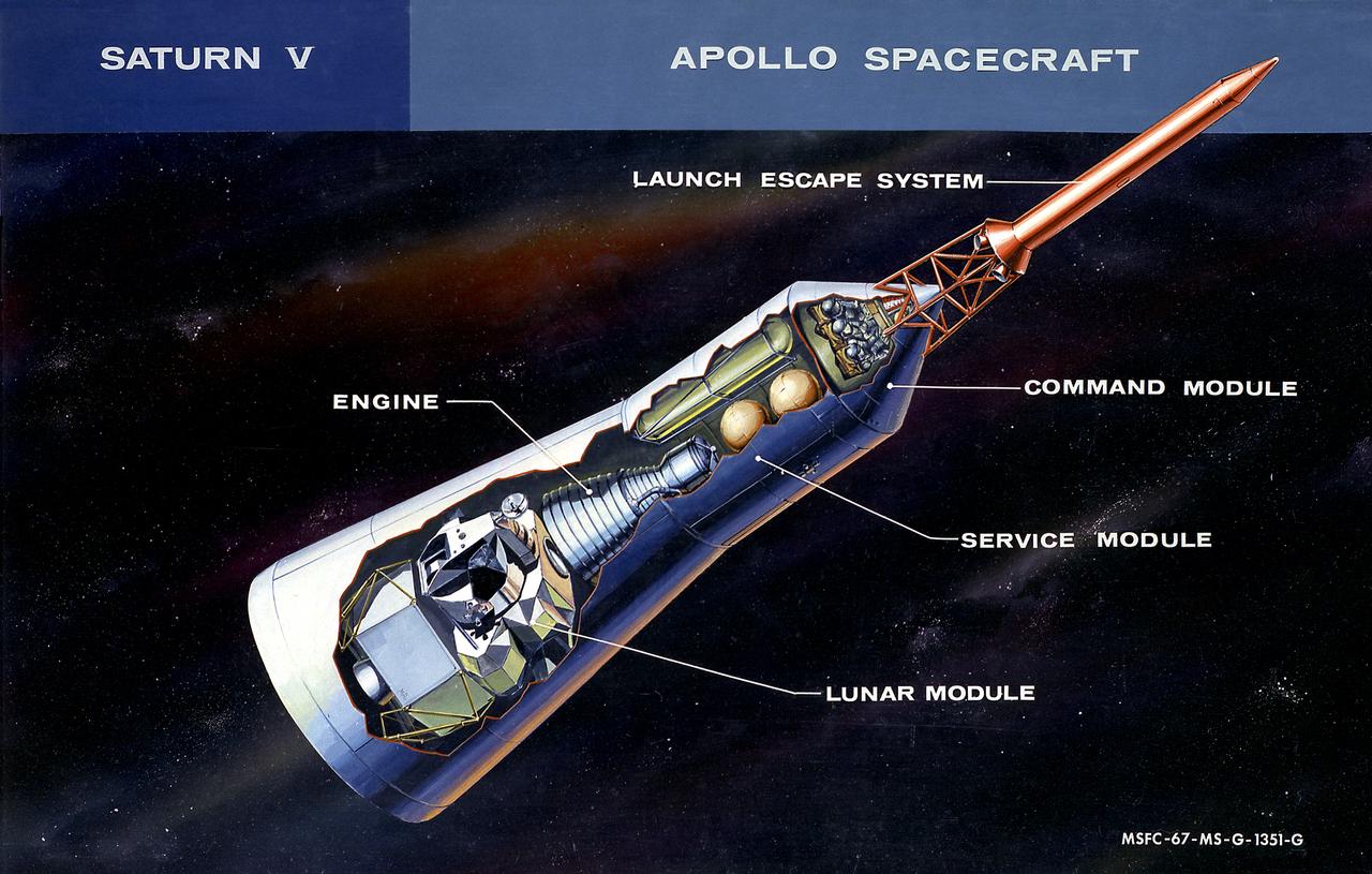
This cutaway illustration shows the Apollo Spacecraft with callouts of the major components. The spacecraft consisted of the lunar module, the service module, the command module, and the launch escape system.
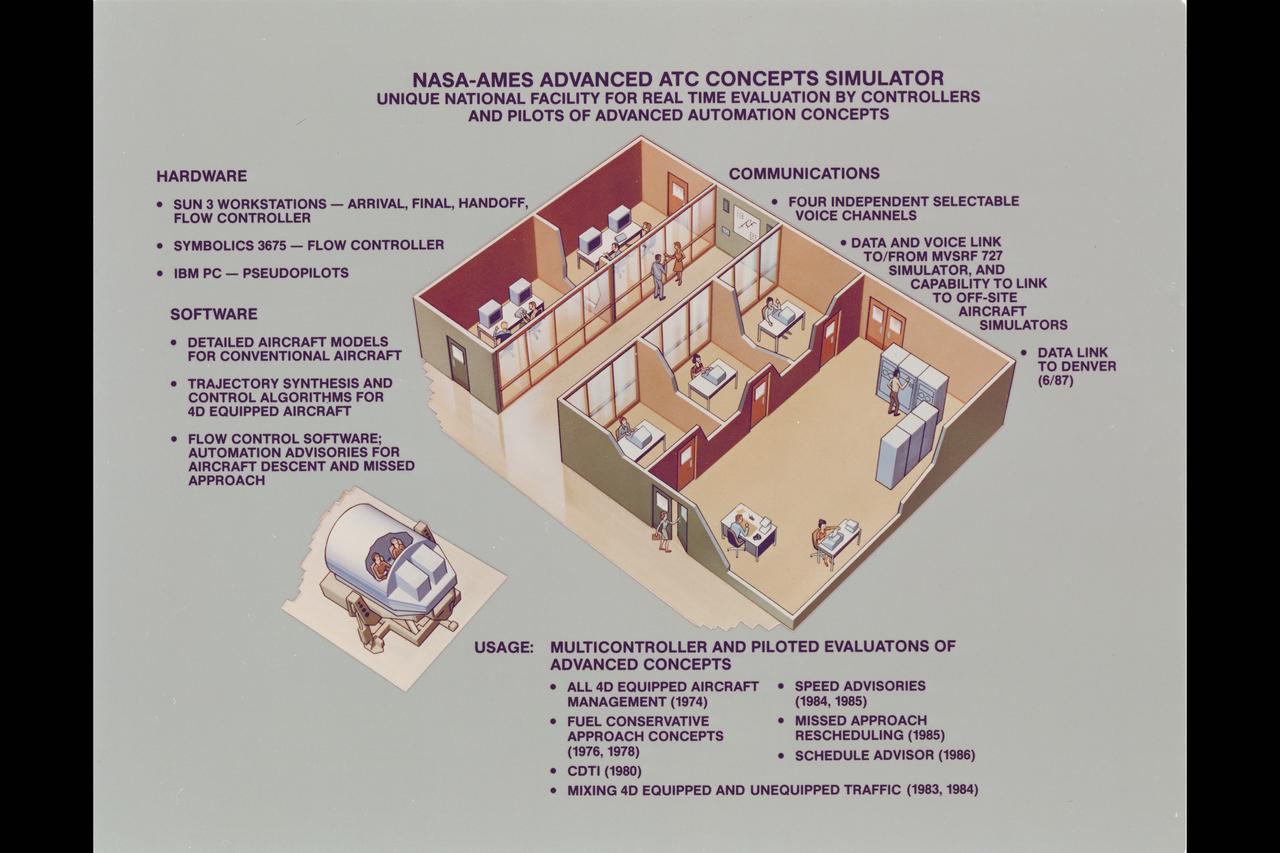
Illustration N-257 Advanced ATC Concepts simulator: unicqu national facility for treal time evalation by controllers and pilots of advanced automation concepts (Cutaway artwork)
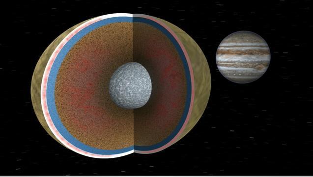
In this image, Europa is seen in a cutaway view through two cycles of its 3.5 day orbit about the giant planet Jupiter. Like Earth, Europa is thought to have an iron core, a rocky mantle and a surface ocean of salty water. Animation available at the Photo

This artist's rendering showing a cutaway view into the interior of Saturn's moon Enceladus. NASA's Cassini spacecraft discovered the moon has a global ocean and likely hydrothermal activity. A plume of ice particles, water vapor and organic molecules sprays from fractures in the moon's south polar region. This graphic is an update to a previously published version (see PIA19656) that did not show the ice and ocean layers to scale. The revised graphic more accurately represents scientists' current understanding of the thickness of the layers. http://photojournal.jpl.nasa.gov/catalog/PIA20013
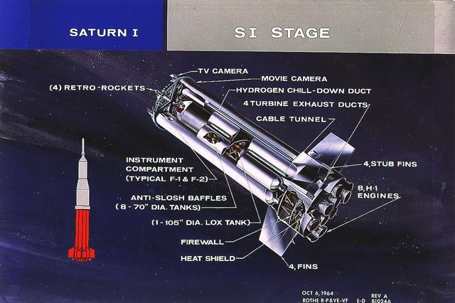
This cutaway illustrates the S-I stage, the first stage of the Saturn I vehicle developed by the Marshall Space Flight Center (MSFC). The stage was propelled by a cluster of eight H-1 engines, capable of producing 1,500,000 pounds of thrust.
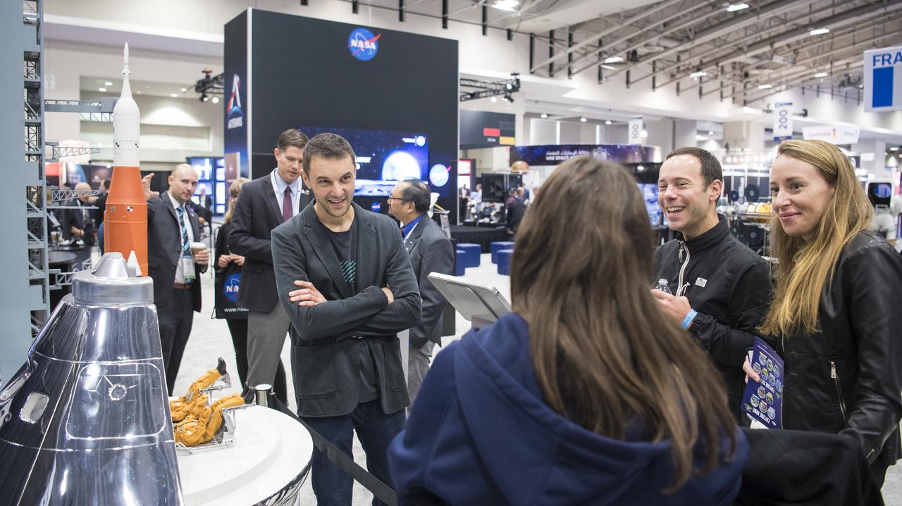
Visitors to the NASA exhibit at the 70th International Astronautical Congress view a cutaway model of the agency’s Orion spacecraft, Friday, Oct. 25, 2019, at the Walter E. Washington Convention Center in Washington. Photo Credit: (NASA/Joel Kowsky)
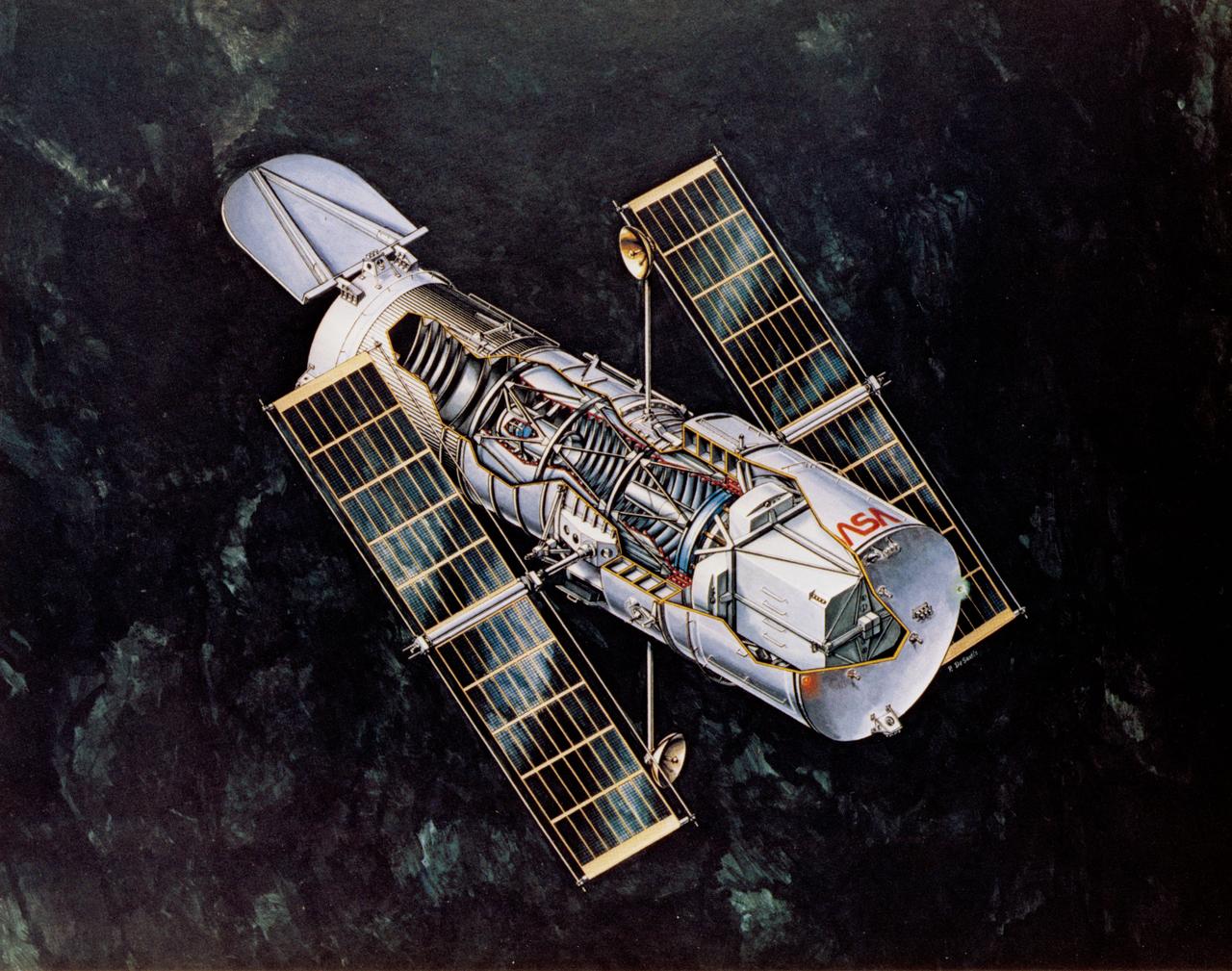
Artist Concept views of the Hubble Space Telescope, one with two Astronauts out on Extravehicular Activity (EVA) and a cutaway view of the telescope. 1. SHUTTLE - Payloads (Hubble Telescope)
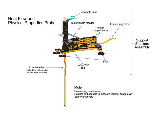
An artist's concept of InSight's heat probe, called the Heat and Physical Properties Package (HP3), annotates various parts inside of the instrument. https://photojournal.jpl.nasa.gov/catalog/PIA23045
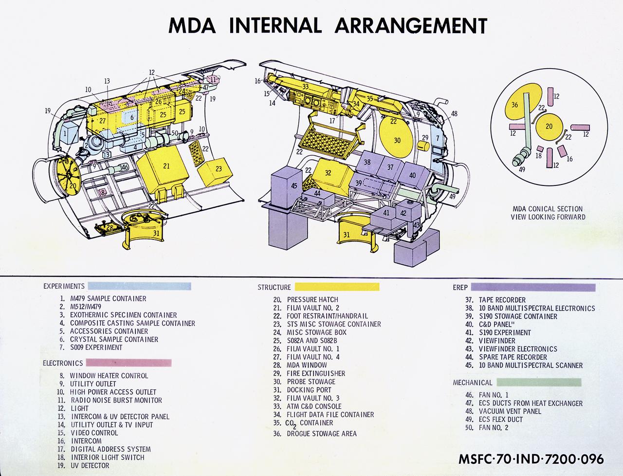
This cutaway drawing details the internal design of the Skylab Multiple Docking Adapter (MDA). The MDA, built under the direction of the Marshall Space Flight Center, housed various Skylab control and experiment units, and provided a docking port for the Apollo Command Module (CM).

S68-41156 (August 1968) --- North American Rockwell Corporation artist's concept depicting the Apollo Command Module, oriented in a blunt and forward attitude, reentering Earth's atmosphere after returning from a trip to the moon. Cutaway view illustrates position of the three astronauts in the Command Module.
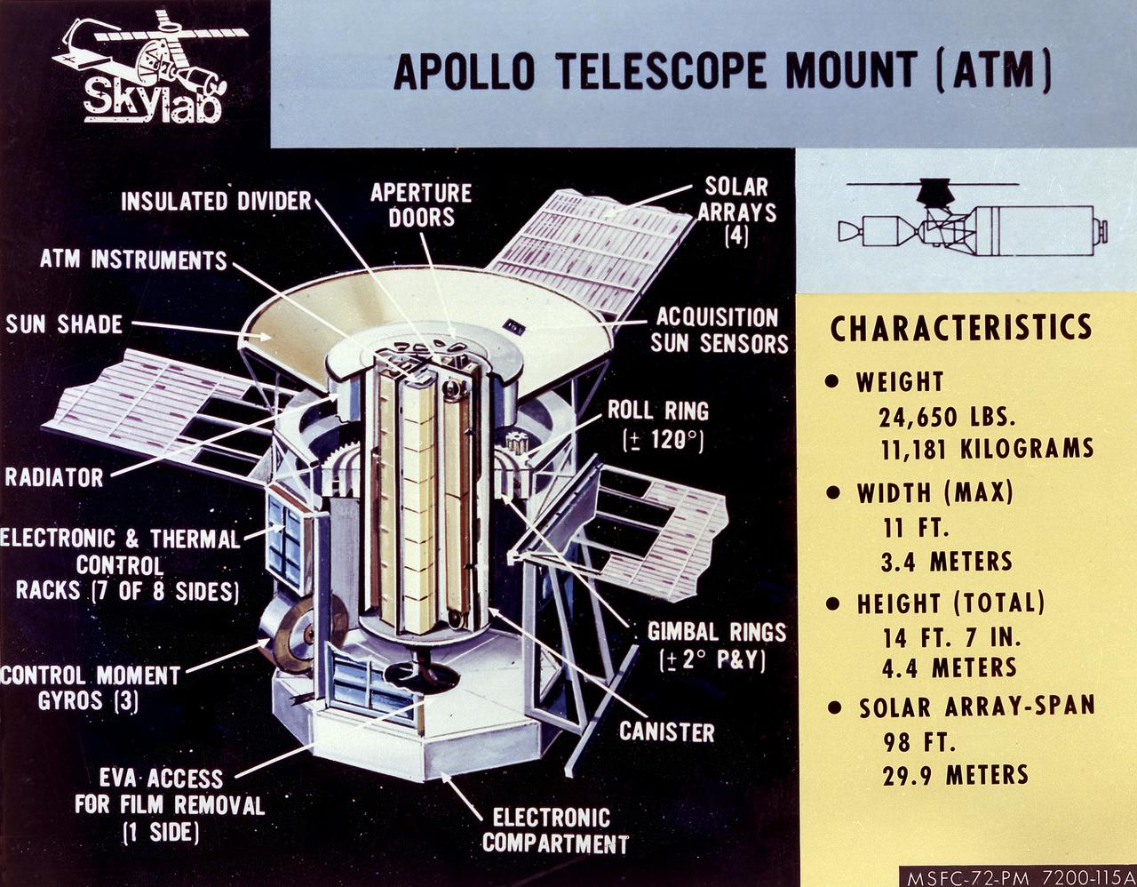
The Apollo Telescope Mount (ATM) served as the first marned astronomical observatory in space. It was designed for solar research from Earth orbit aboard the Skylab. This image is a cutaway illustration of the ATM canister with callouts and characteristics. The ATM was designed and developed by the Marshall Space Flight Center.
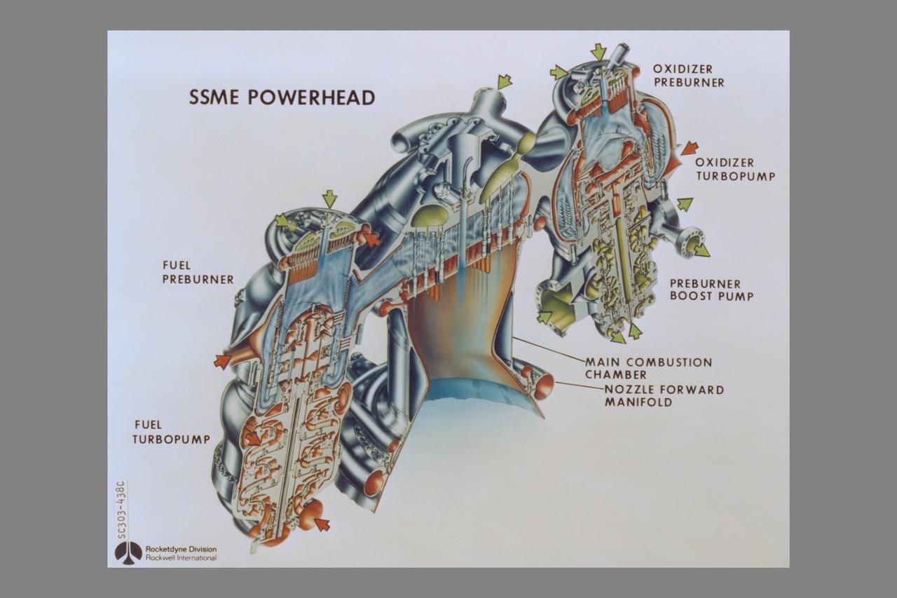
cutaway Rockwell International Space Shuttle Main Engines: Powerhead (Left side - fuel preburner, fuel trubopump - Center - Main Combustion Chamber, nozzle forward manifold - Right side - oxidizer preburner, oxidizer turbopump, preburner boost pump)
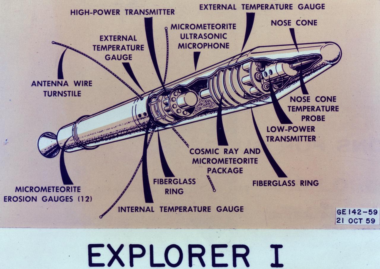
This image is a cutaway illustration of the Explorer I satellite with callouts. The Explorer I satellite was America's first scientific satellite launched aboard the Jupiter C launch vehicle on January 31, 1958. The Explorer I carried the radiation detection experiment designed by Dr. James Van Allen and discovered the Van Allen Radiation Belt.
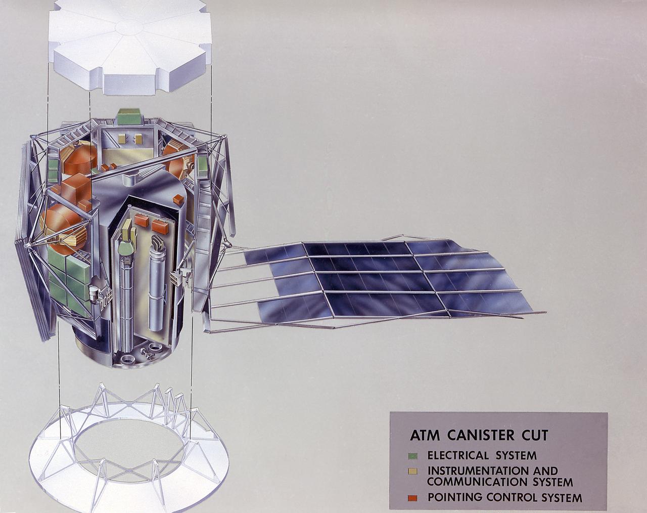
The Apollo Telescope Mount (ATM) served as the first marned astronomical observatory in space. It was designed for solar research from Earth orbit aboard the Skylab. This image is a cutaway illustration of the ATM canister. The ATM was designed and developed by the Marshall Space Flight Center.
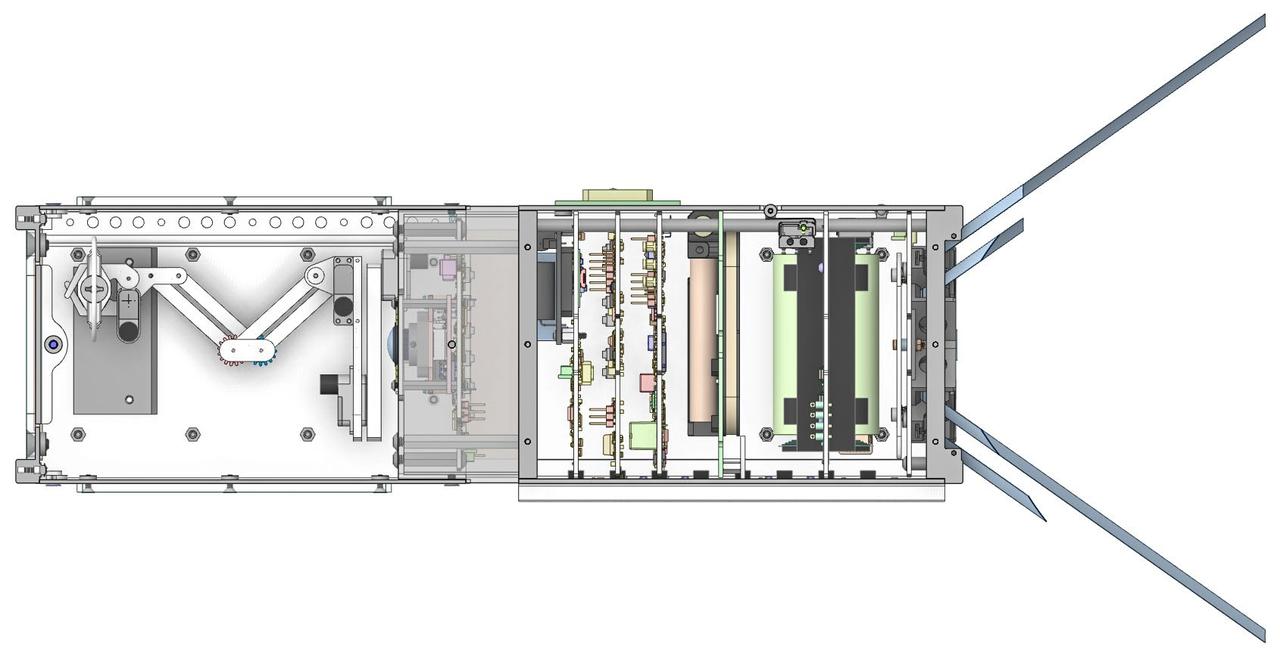
jsc2025e039324 (4/17/2025) --- Graphic of the Foras Promineo CubeSat cutaway view is seen. The Foras Promineo CubeSat engages the public with space technology by allowing individuals to control a robot arm to grasp free-floating objects inside the satellite. Image courtesy of Sierra Lobo.
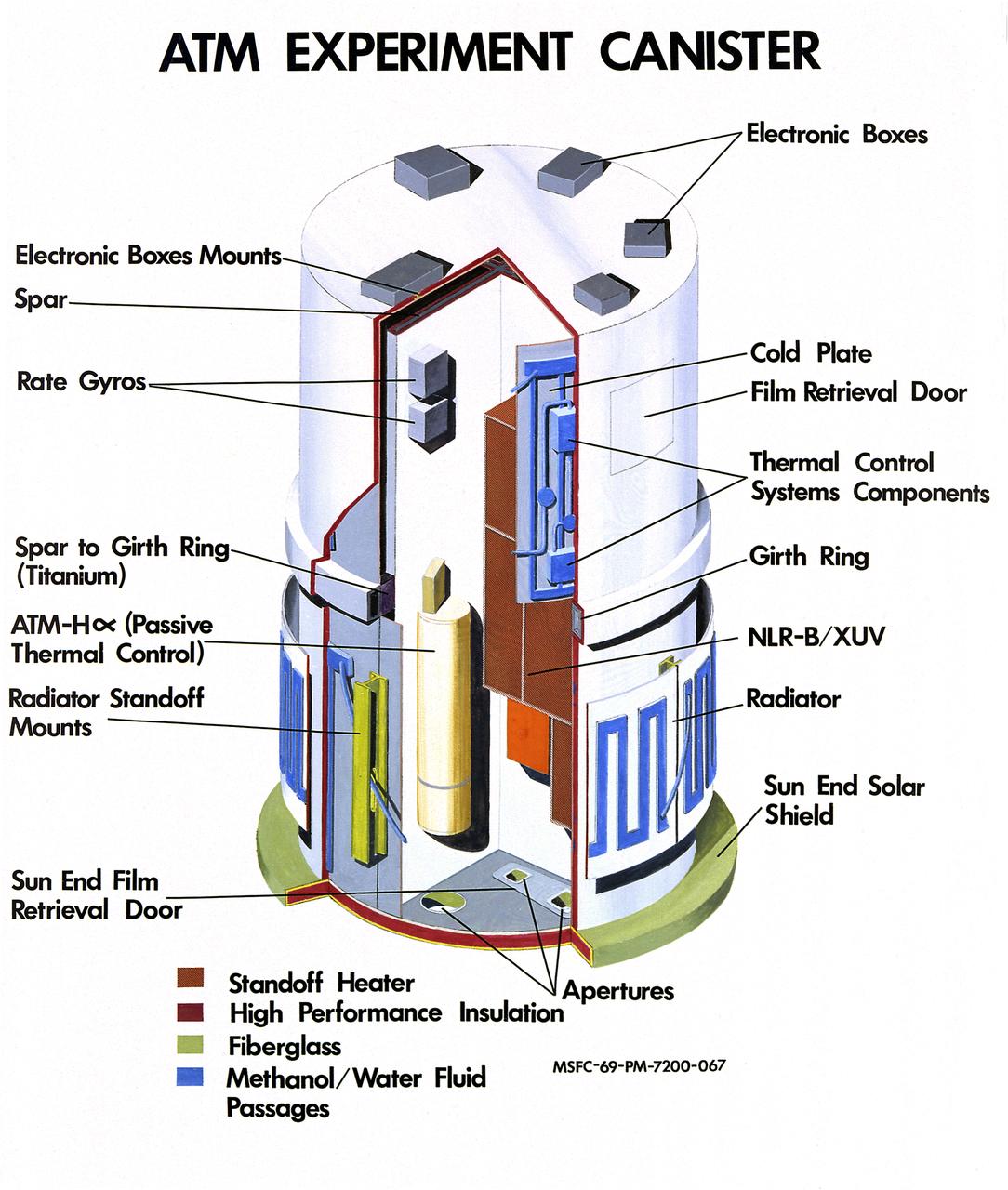
The Apollo Telescope Mount (ATM) served as the first marned astronomical observatory in space. It was designed for solar research from Earth orbit aboard the Skylab. This image is a cutaway illustration of the ATM canister with callouts. The ATM was designed and developed by the Marshall Space Flight Center.
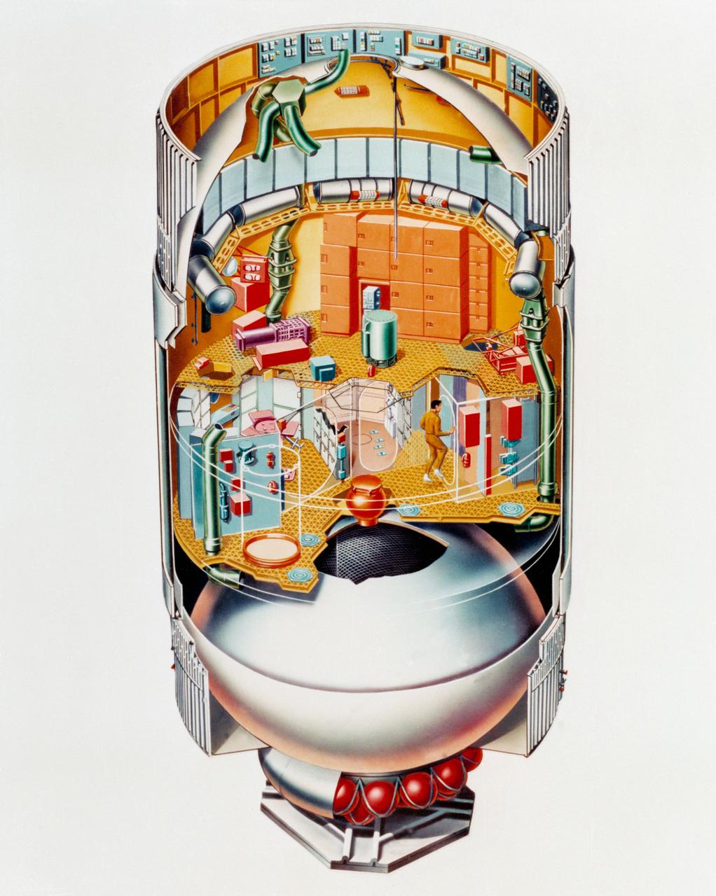
S73-24316 (May 1973) --- An artist's concept illustrating a cutaway view of the Skylab 1 Orbital Workshop (OWS). The OWS is one of the five major components of the Skylab 1 space station cluster which was launched by a Saturn V on May 14, 1973 into Earth orbit. Photo credit: NASA
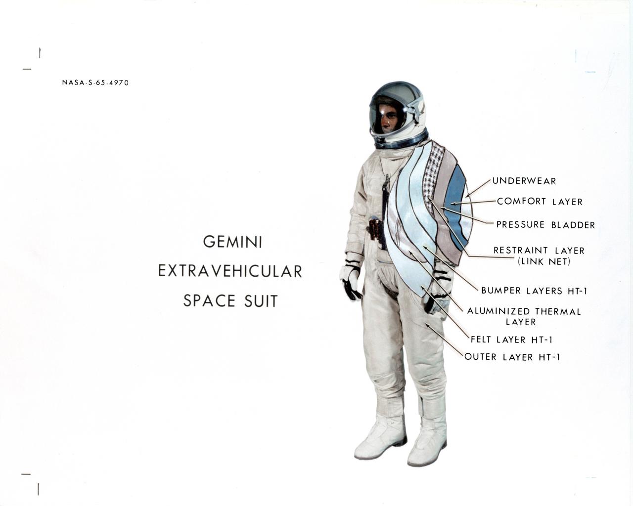
S65-04970 (May 1965) --- Cut-away view of the Gemini extravehicular spacesuit showing the suits different layers.
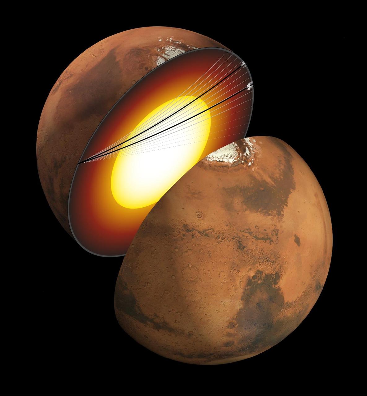
This artist's concept shows a cutaway of Mars along with the paths of seismic waves from two separate quakes in 2021. These seismic waves, detected by NASA's InSight mission, were the first ever identified to enter another planet's core. InSight's seismometer allowed scientists to study these waves and gain an unprecedented look at the Martian core. The quakes were detailed in a paper published April 24, 2023, in the Proceedings of the National Academies of Sciences. Occurring on Aug. 25 and Sept. 18, 2021, the two temblors were the first identified by the InSight team to have originated on the opposite side of the planet from the lander – so-called farside quakes. The distance proved crucial: The farther a quake happens from InSight, the deeper into the planet its seismic waves can travel before being detected. https://photojournal.jpl.nasa.gov/catalog/PIA25827
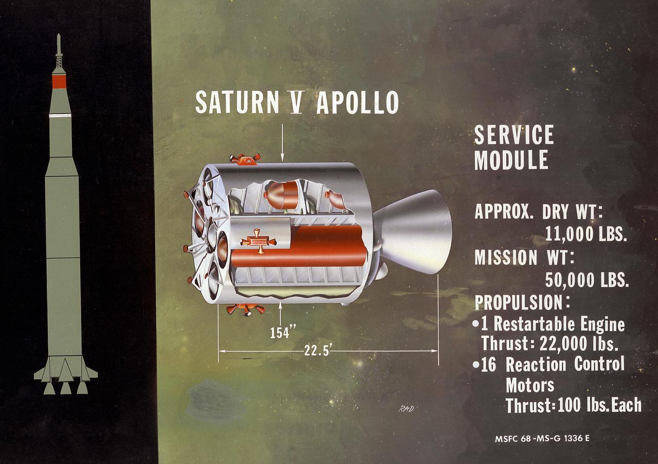
This is a cutaway illustration of the Saturn V service module configuration. Packed with plumbing and tanks, the service module was the command module's constant companion until just before reentry. All components not needed during the last few minutes of flight, and therefore requiring no protection against reentry heat, were transported in this module. It carried oxygen for most of the trip, fuel cells to generate electricity (along with the oxygen and hydrogen to run them); small engines to control pitch, roll, and yaw; and a large engine to propel the spacecraft into, and out of, lunar orbit.
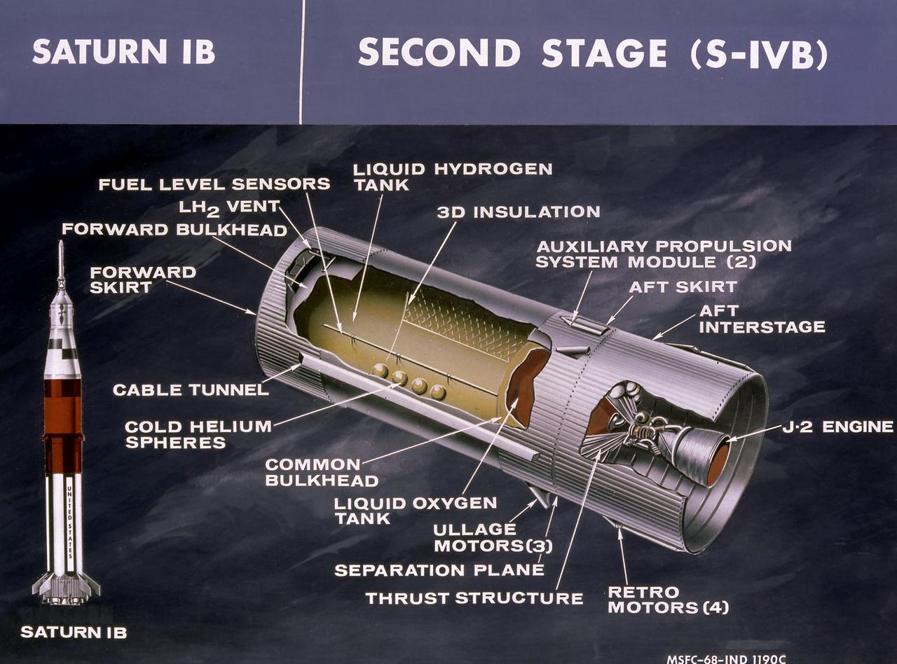
This cutaway drawing shows the S-IVB stage in its Saturn IB configuration. As a part of the Marshall Space Flight Center's (MSFC) "building block" approach to the Saturn development, the S-IVB stage was utilized in the Saturn IB launch vehicle as a second stage and, later, the Saturn V launch vehicle as a third stage. The stage was powered by a single J-2 engine, initially capable of 200,000 pounds of thrust.
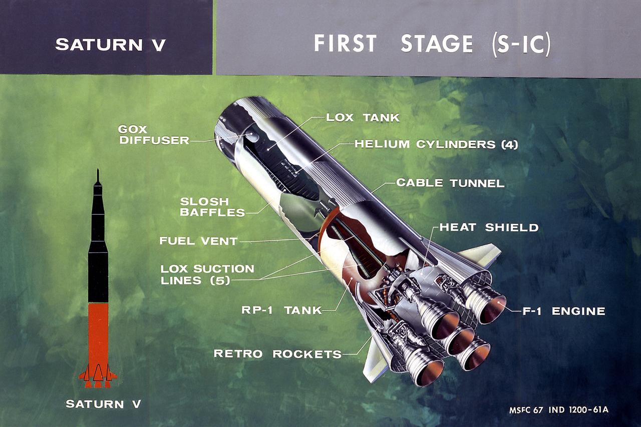
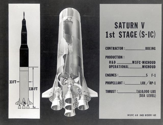
This illustration shows a cutaway drawing with callouts of the major components for the S-IC (first) stage of the Saturn V launch vehicle. The S-IC stage is 138 feet long and 33 feet in diameter, producing more than 7,500,000 pounds of thrust through five F-1 engines powered by liquid oxygen and kerosene. Four of the engines are mounted on an outer ring and gimball for control purposes. The fifth engine is rigidly mounted in the center. When ignited, the roar produced by the five engines equals the sound of 8,000,000 hi-fi sets.
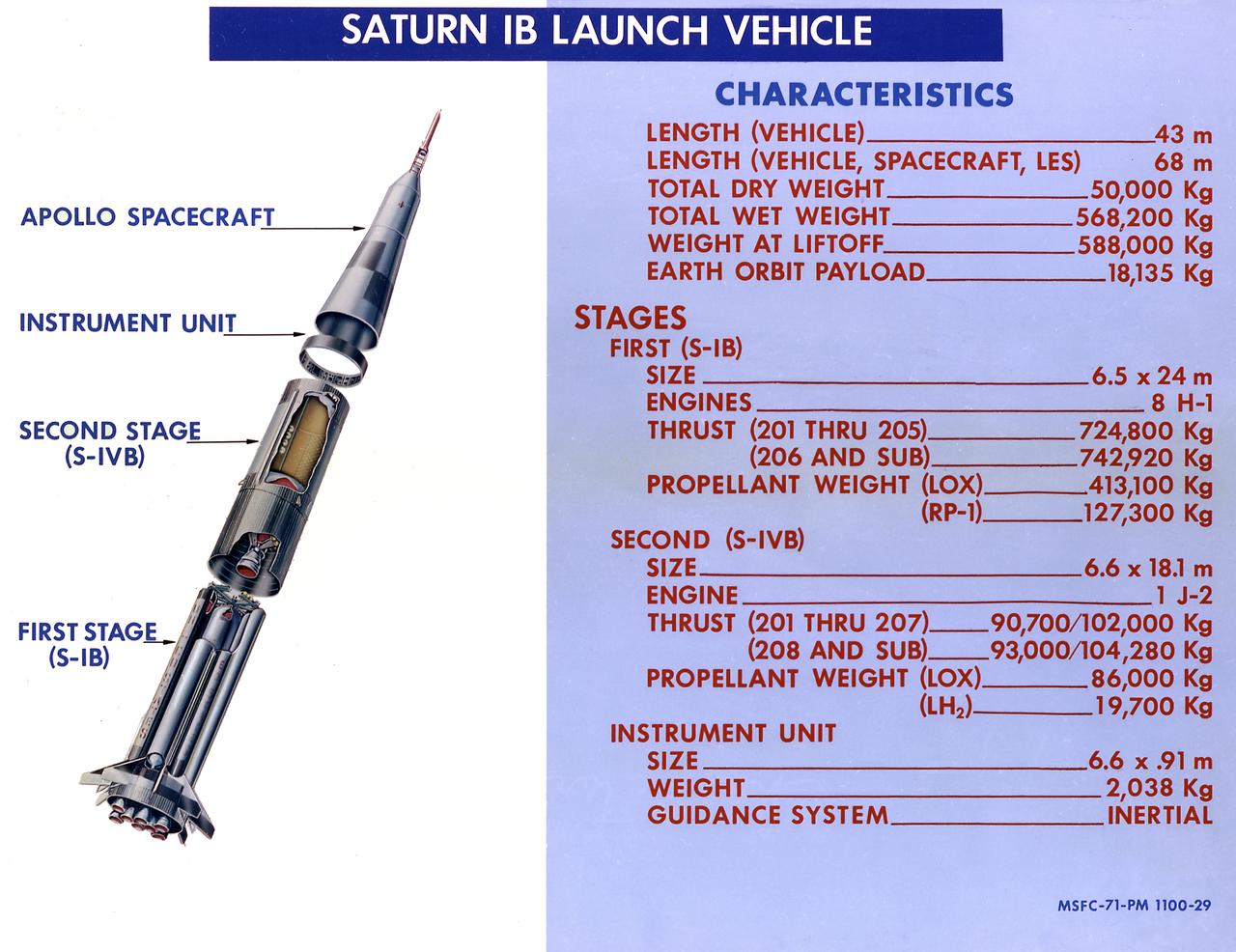
This 1968 cutaway drawing illustrates the Saturn IB launch vehicle with its two booster stages, the S-IB (first stage) and S-IVB (second stage), and provides the vital statistics in metric units. Developed by the Marshall Space Flight Center (MSFC) as an interim vehicle in MSFC's "building block" approach to the Saturn rocket development, the Saturn IB utilized Saturn I technology to further develop and refine the larger boosters and the Apollo spacecraft capabilities required for the marned lunar missions.
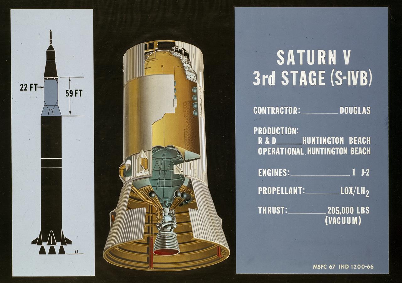
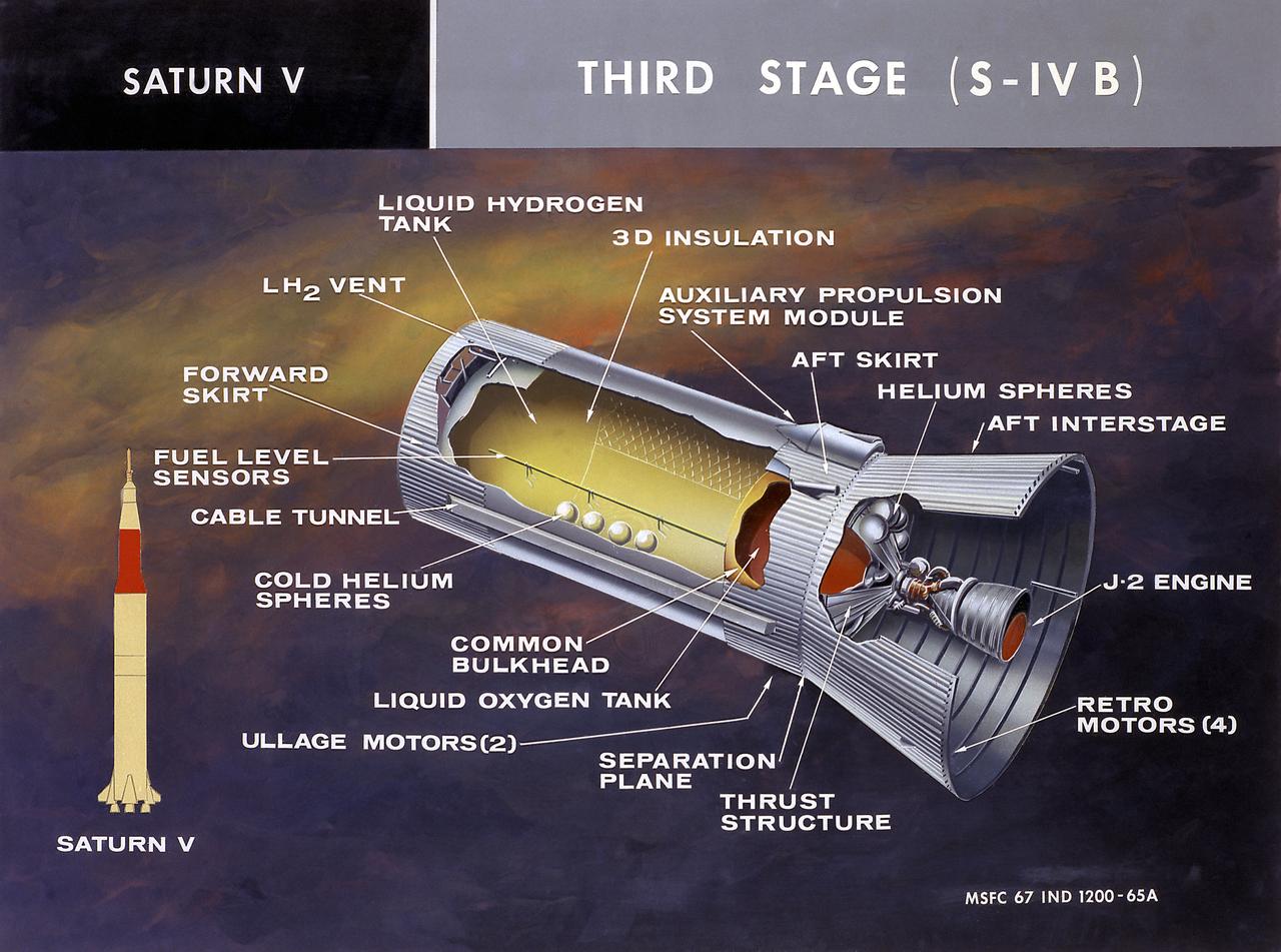
This cutaway drawing shows the S-IVB (third stage) of the Saturn V launch vehicle. As a part of the Marshall Space Flight Center’s (MSFC) “building block” approach to the Saturn development, the S-IVB stage was utilized in the Saturn IB launch vehicle as a second stage and, later, the Saturn V launch vehicle as a third stage. The 59 foot long and 22 feet diameter stage was powered by a single J-2 engine, initially capable of 200,000 pounds of thrust.
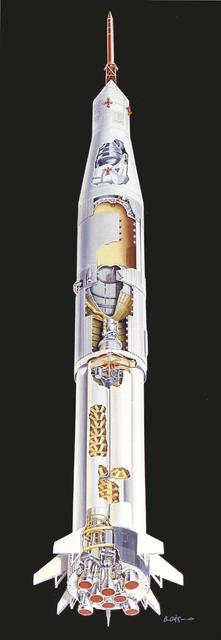
This undated cutaway drawing illustrates the Saturn IB launch vehicle with its two booster stages, the S-IB and S-IVB. Developed by the Marshall Space Flight Center (MSFC) as an interim vehicle in MSFC's "building block" approach to the Saturn rocket development, the Saturn IB utilized Saturn I technology to further develop and refine the larger boosters and the Apollo spacecraft capabilities required for the marned lunar missions.
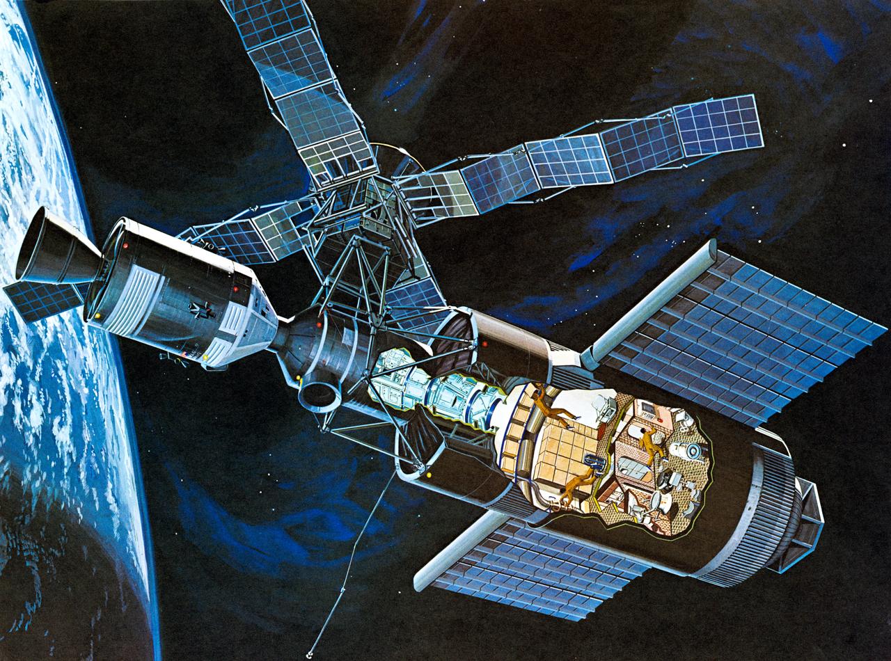
S71-52192 (1971) --- An artist's concept of the Skylab space station cluster in Earth's orbit. The cutaway view shows astronaut activity in the Orbital Workshop (OWS). The Skylab cluster is composed of the OWS, Airlock Module (AM), Multiple Docking Adapter (MDA), Apollo Telescope Mount (ATM), and the Command and Service Module (CSM). Photo credit: NASA
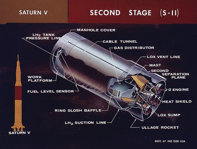
This cutaway illustration shows the Saturn V S-II (second) stage with callouts of major components. When the Saturn V first stage burns out and drops away, power for the Saturn was provided by the S-II (second) stage with five J-2 engines which produced a total of 1,150,000 pounds of thrust. Four outer engines are placed in a square pattern with gimbaling capability for control and guidance, with the fifth engine fixed rigidly in the center.
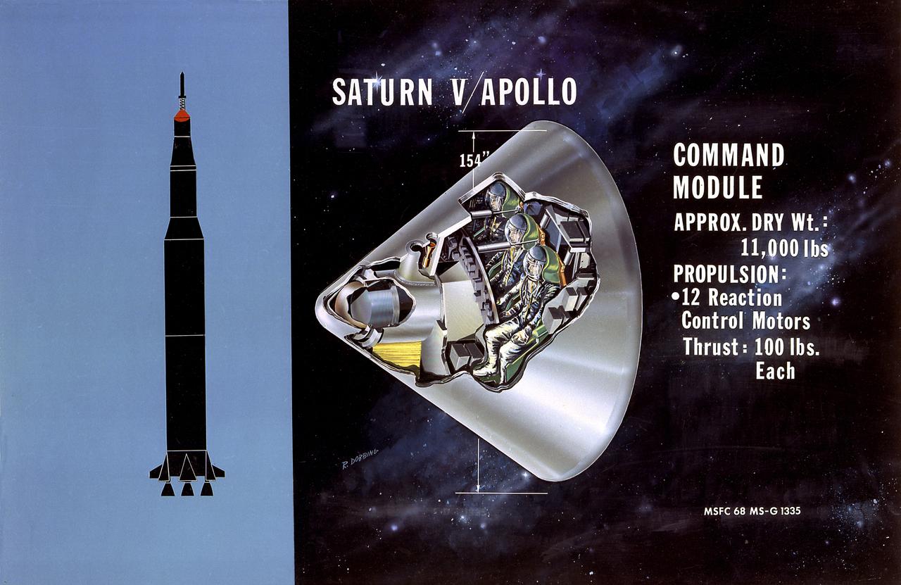
This is a cutaway illustration of the Saturn V command module (CM) configuration. The CM was crammed with some of the most complex equipment ever sent into space at the time. The three astronaut couches were surrounded by instrument panels, navigation gear, radios, life-support systems, and small engines to keep it stable during reentry. The entire cone, 11 feet long and 13 feet in diameter, was protected by a charring heat shield. The 6.5 ton CM was all that was finally left of the 3,000-ton Saturn V vehicle that lifted off on the journey to the Moon.
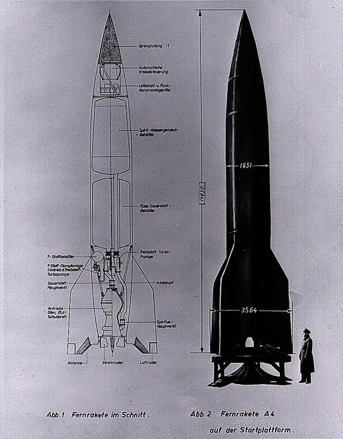
This German cutaway drawing of the Aggregate-4 (A-4) illustrates the dimensions and internal workings of the rocket. Later renamed the V-2, the rocket was developed by Dr. Wernher von Braun and the German Rocket Team at Peenemuende on the Baltic Sea. At the end of World War II, the team of German engineers and scientists came to the United States to work for the Army at Fort Bliss, Texas, and Redstone Arsenal in Huntsville, Alabama.
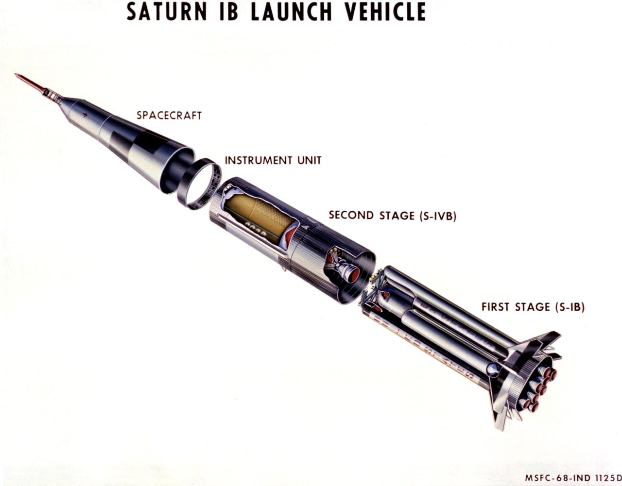
This 1968 cutaway drawing illustrates the Saturn IB launch vehicle with its two booster stages, the S-IB and S-IVB. Developed by the Marshall Space Flight Center (MSFC) as an interim vehicle in MSFC's "building block" approach to the Saturn rocket development, the Saturn IB utilized Saturn I technology to further develop and refine the larger boosters and the Apollo spacecraft capabilities required for the marned lunar mission.
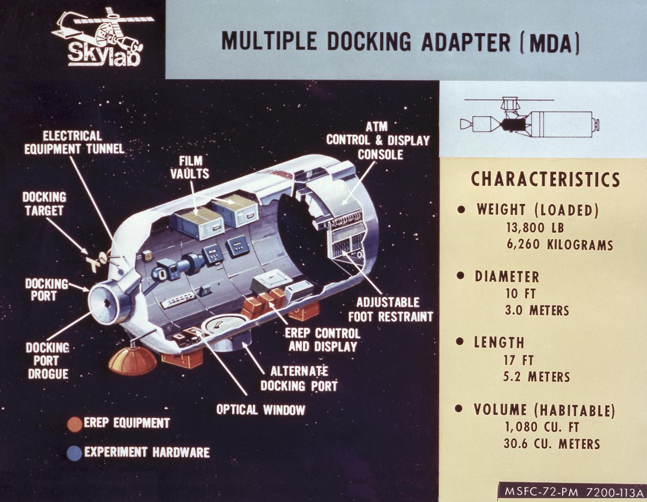
This cutaway drawing details the major characteristics of the Skylab Multiple Docking Adapter (MDA). The MDA, built under the direction of the Marshall Space Flight Center, housed the control units for the Apollo Telescope Mount (ATM), Earth Resources Experiment Package (EREP), and Zero-Gravity Materials Processing Facility, and provided a docking port for the Apollo Command Module (CM).
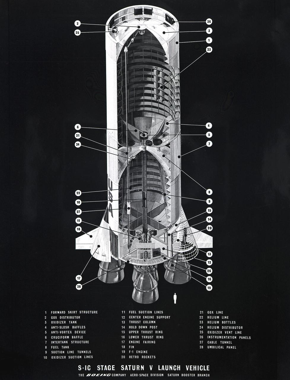
This cutaway illustration shows the Saturn V S-IC (first) stage with detailed callouts of the components. The S-IC Stage is 138 feet long and 33 feet in diameter, producing 7,500,000 pounds of thrust through five F-1 engines that are powered by liquid oxygen and kerosene. Four of the engines are mounted on an outer ring and gimbal for control purposes. The fifth engine is rigidly mounted in the center. When ignited, the roar produced by the five engines equals the sound of 8,000,000 hi-fi sets.
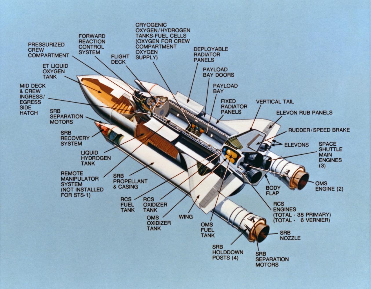
S81-30630 (February 1981) --- This "cutaway" artist's concept exercises some artistic license to reveal systems of the major components of a space shuttle vehicle. With its payload bay doors open here, the shuttle's cryogenic supply station (note cutaway) and the deployable radiator panels (visible) can be seen. In reality, the cargo bay panels would never be open while the orbiter is attached to the solid rocket boosters (SRB) and external fuel tank (ET). The thick-bodied, delta-winged aerospace craft is 37 meters long, has a span of 24 meters (120 feet by 80 feet), and weighs about 75,000 kilograms empty (165,000 lbs). Its payload bay, 18.3 meters long and 4.6 meters in diameter (60 feet by 15 feet) can deliver single or conglomerate payloads of up to 370 kilometers altitude or smaller loads up to 1110 kilometers (230 miles to 690 miles). It can bring payloads of 14,515 kilograms (32,000 lbs) back to Earth and it can carry out a variety of missions lasting seven to 30 days. Photo credit: NASA
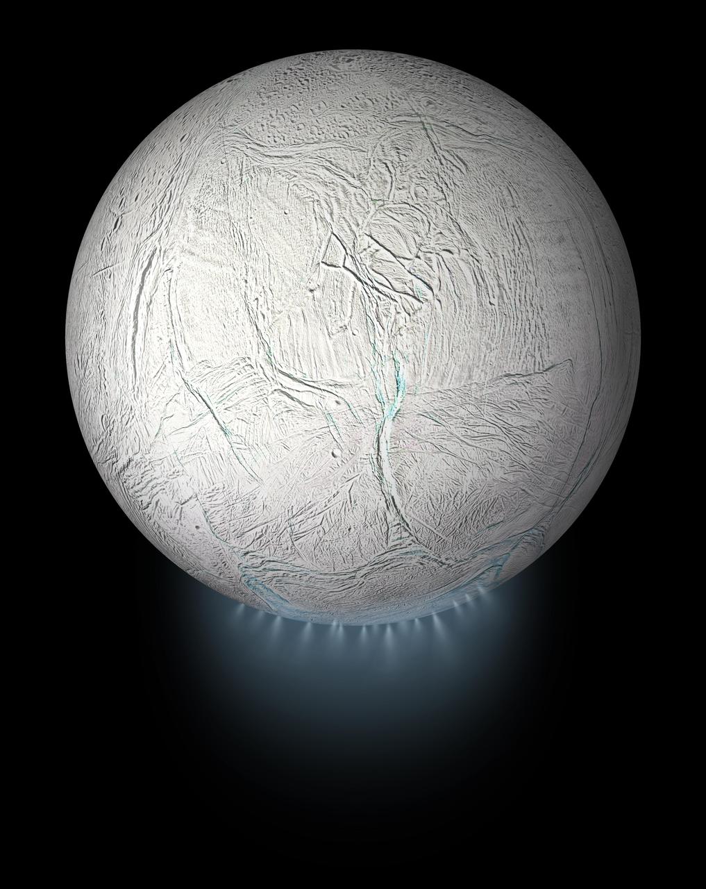
This illustration shows Saturn's icy moon Enceladus with the plume of ice particles, water vapor and organic molecules that sprays from fractures in the moon's south polar region. A cutaway version of this graphic is also available, showing the moon's interior ocean and hydrothermal activity — both of which were discovered by NASA's Cassini mission (see PIA20013). This global view was created using a Cassini-derived map of Enceladus (see PIA18435). More information about Enceladus is available at https://solarsystem.nasa.gov/moons/saturn-moons/enceladus/in-depth/. For more information about the Cassini-Huygens mission visit https://solarsystem.nasa.gov/missions/cassini/overview/. https://photojournal.jpl.nasa.gov/catalog/PIA23175
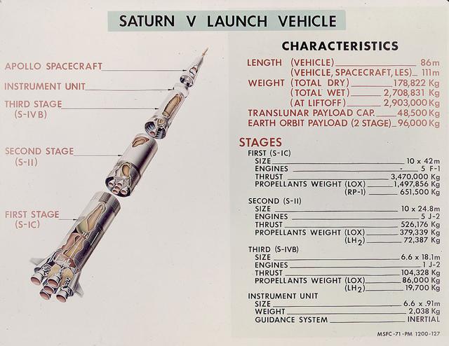
This is a good cutaway diagram of the Saturn V launch vehicle showing the three stages, the instrument unit, and the Apollo spacecraft. The chart on the right presents the basic technical data in clear metric detail. The Saturn V is the largest and most powerful launch vehicle in the United States. The towering, 111 meter, Saturn V was a multistage, multiengine launch vehicle standing taller than the Statue of Liberty. Altogether, the Saturn V engines produced as much power as 85 Hoover Dams. Development of the Saturn V was the responsibility of the Marshall Space Flight Center at Huntsville, Alabama, directed by Dr. Wernher von Braun.
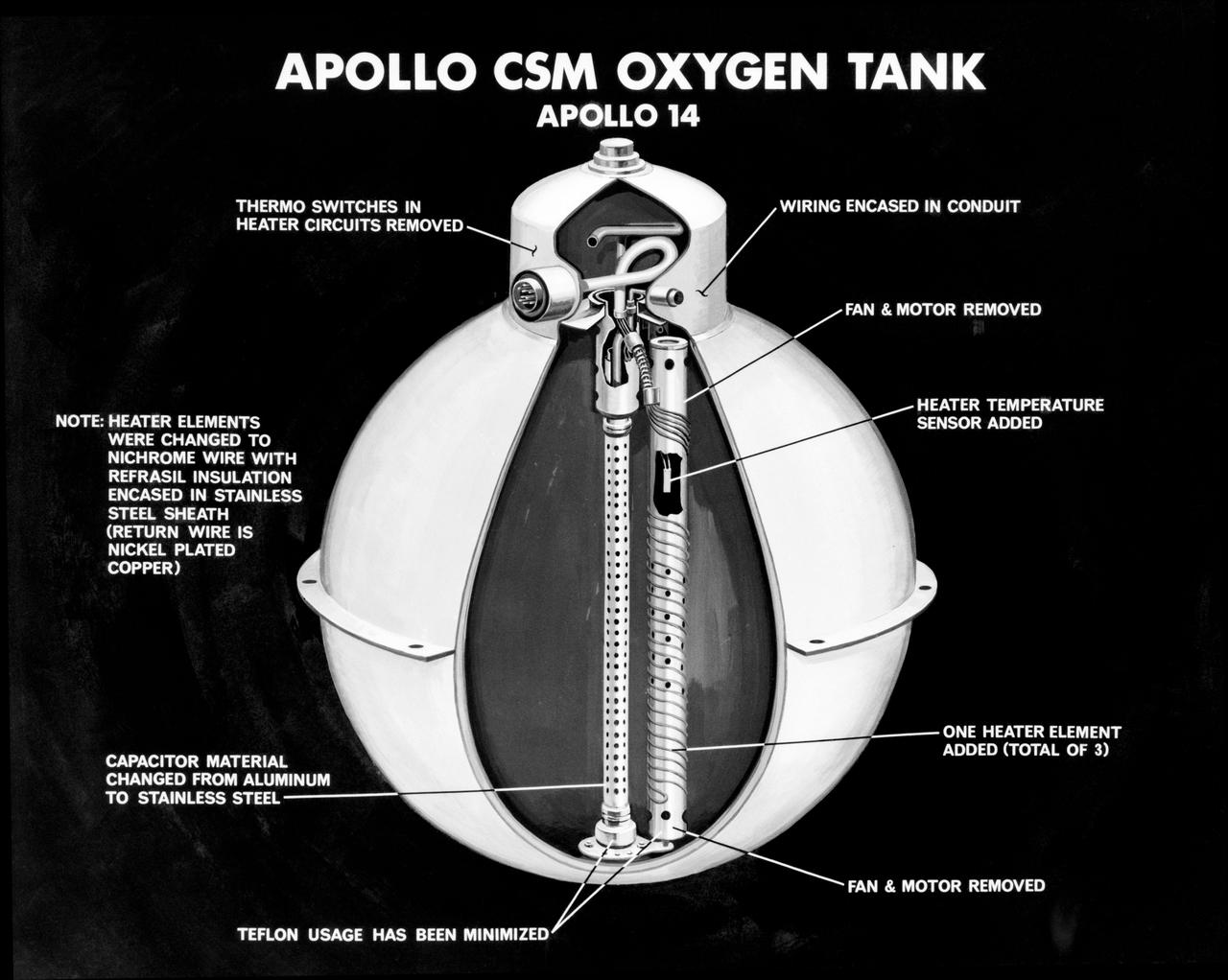
S71-16745 (January 1971) --- An artist's concept illustrating a cutaway view of one of the three oxygen tanks of the Apollo 14 spacecraft. This is the new Apollo oxygen tank design, developed since the Apollo 13 oxygen tank explosion. Apollo 14 has three oxygen tanks redesigned to eliminate ignition sources, minimize the use of combustible materials, and simplify the fabrication process. The third tank has been added to the Apollo 14 Service Module, located in the SM's sector one, apart from the pair of oxygen tanks in sector four. Arrows point out various features of the oxygen tank.
This cutaway illustration shows the Saturn V S-IVB (third) stage with the callouts of its major components. When the S-II (second) stage of the powerful Saturn V rocket burnt out and was separated the remaining units approached orbit around the Earth. Injection into the desired orbit was attaineded as the S-IVB (third stage) was ignited and burnt. The S-IVB stage was powered by a single 200,000-pound thrust J-2 engine and had a re-start capability built in for its J-2 engine. The S-IVB restarted to speed the Apollo spacecraft to escape velocity injecting it and the astronauts into a moon trajectory.
This is a cutaway view of the Saturn V first stage, known as the S-IC, detailing the five F-1 engines and fuel cells. The S-IC stage is 138 feet long and 33 feet in diameter, producing more than 7,500,000 pounds of thrust through the five F-1 engines that are powered by liquid oxygen and kerosene. Four of the engines are mounted on an outer ring and gimbal for control purposes. The fifth engine is rigidly mounted in the center. When ignited, the roar produced by the five engines equals the sound of 8,000,000 hi-fi sets.
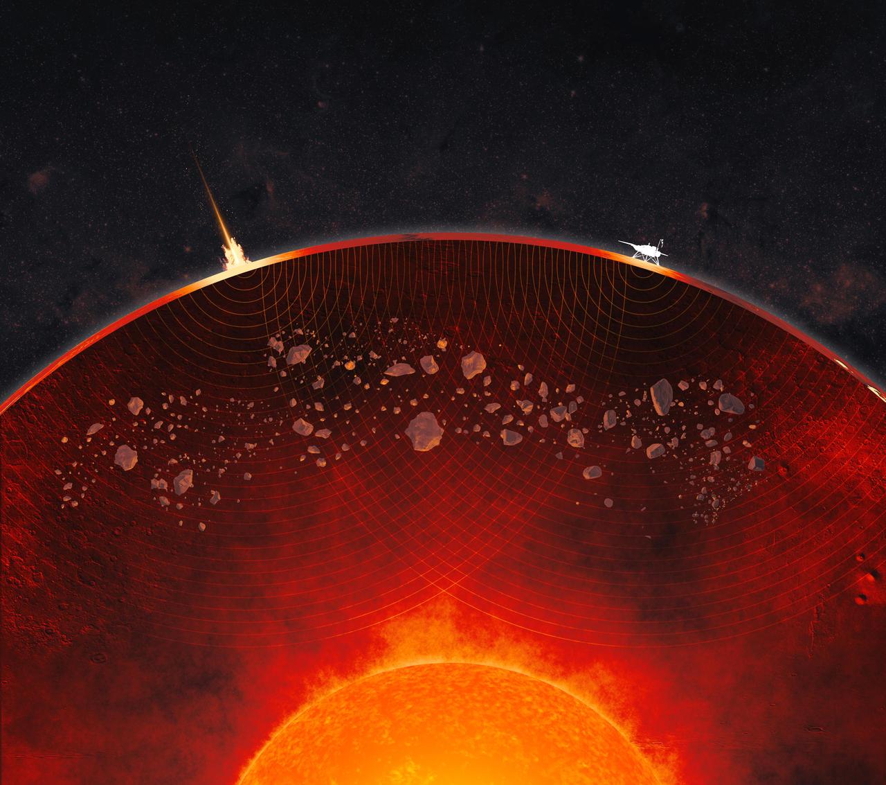
This not-to-scale artist's concept depicts a cutaway view of Mars' interior, revealing the crust, mantle, and core. Debris from ancient impacts lies scattered in the mantle in the form of lumps that are as large as 2.5 miles (4 kilometers) across, data from NASA's InSight Mars lander shows. On the Martian surface at left, a meteoroid impact sends seismic signals (shown as curving concentric lines) through the planet; InSight is depicted at right. InSight placed the first seismometer on Mars' surface in 2018. The extremely sensitive instrument recorded 1,319 marsquakes before the lander ran out of power in 2022, the result of dust caked on its solar panels. Quakes produce seismic waves that change as they pass through different kinds of material, providing scientists with a way to study the interior of a planetary body. To date, the InSight team has measured the size, depth, and composition of Mars' crust, mantle, and core. The impact debris in the Martian mantle offers a geologic record that could be preserved only on worlds like Mars, whose lack of tectonic plates has kept its interior from being churned up the way Earth's is through a process known as convection. https://photojournal.jpl.nasa.gov/catalog/PIA26636
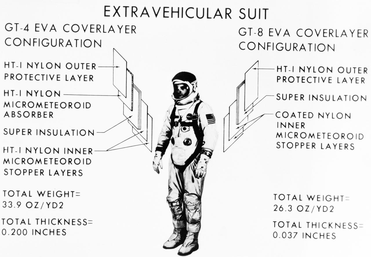
S66-01122 (January 1966) --- Artist concept of the Gemini-4 EVA coverlayer configuration.
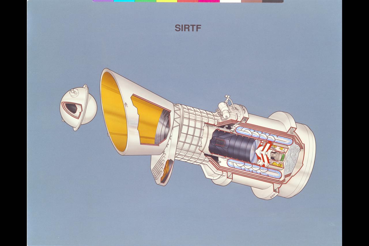
Artist: Rick Guidice SIRTF Artwork update - cutaway Space Infrared Telescope Facility's will orbit at 900 kilometers aboard a platform-type spacecraft, providing power, pointing, and communications to Earth. The telescope and its infrared instruments, will reside within a cylindrical cryogen tank. The hollow walls of the tank will contain the superfluid helium that cools the telescope to its operating temperature, a few degrees above absolute zero. SIRTF will carry three versatile instruments to analyze the radiation it collects, the Multiband Imaging Photometer, the Infrared Array Camera, and the Infrared Spectrograph. SIRTF long lifetime - 5 years or more - will permit astronomers of all disciplines to use the facililty to carry out a wide variety of astrophysical programs. It will provide ongoing coverage of variable objects, such as quasars, as well as the capability to study rare and transient events such as comets and supernovae. SIRTF's long lifetime will also allow it to distinguish nearby objects by detecting their gradual motions relative to the more distant background stars.
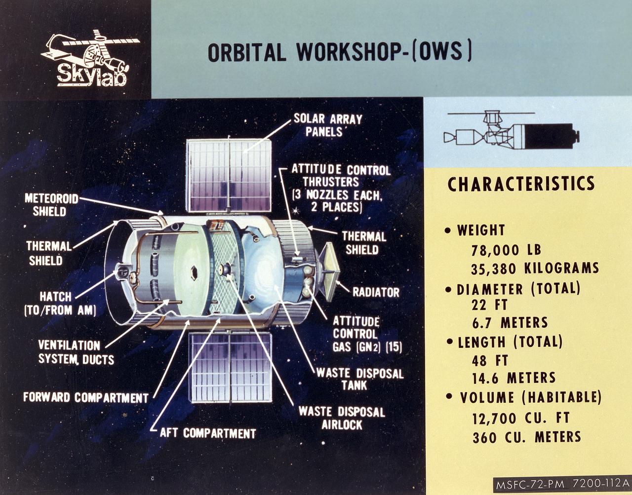
This cutaway illustration shows the characteristics and basic elements of the Skylab Orbiter Workshop (OWS). The OWS was divided into two major compartments. The lower level provided crew accommodations for sleeping, food preparation and consumption, hygiene, waste processing and disposal, and performance of certain experiments. The upper level consisted of a large work area and housed water storage tanks, a food freezer, storage vaults for film, scientific airlocks, mobility and stability experiment equipment, and other experimental equipment. The compartment below the crew quarters was a container for liquid and solid waste and trash accumulated throughout the mission. A solar array, consisting of two wings covered on one side with solar cells, was mounted outside the workshop to generate electrical power to augment the power generated by another solar array mounted on the solar observatory. Thrusters were provided at one end of the workshop for short-term control of the attitude of the space station.
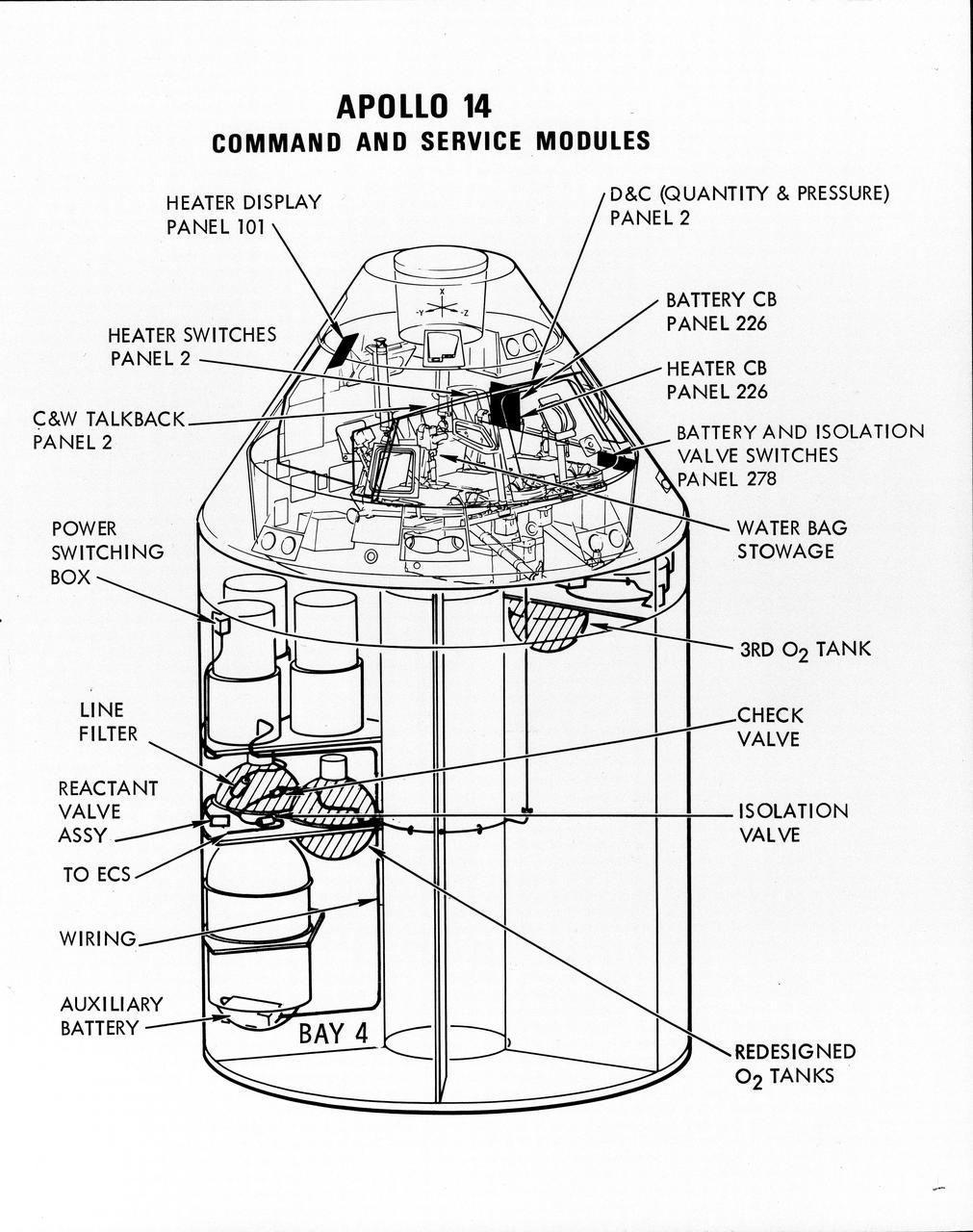
S71-16823 (January 1971) --- A line drawing illustrating a cutaway view of the Apollo 14 Command and Service Modules, showing the engineering changes in the CSM which were recommended by the Apollo 13 Review Board. (The Apollo 13 abort was caused by a short circuit and wiring overheating in one of the SM cryogenic oxygen tanks.) The major changes to the Apollo 14 CSM include adding a third cryogenic oxygen tank installed in a heretofore empty bay (in sector one) of the SM, addition of an auxiliary battery in the SM as a backup in case of fuel cell failure, and removal of destratification fans in the cryogenic oxygen tanks and removal of thermostat switches from the oxygen tank heater circuits. Provision for stowage of an emergency five-gallon supply of drinking water has been added to the CM.
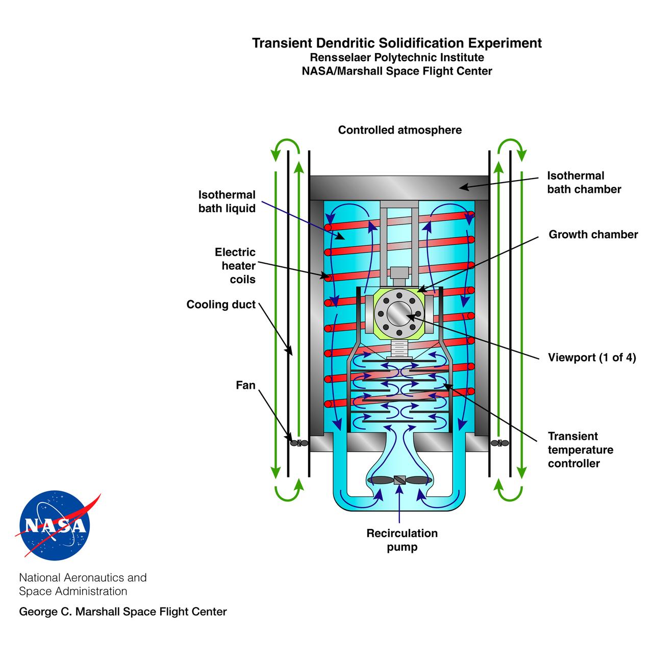
The Transient Dentritic Solidification Experiment (TDSE) is being developed as a candidate for flight aboard the International Space Station. TDSE will study the growth of dentrites (treelike crystalline structures) in a transparent material (succinonitrile or SCN) that mimics the behavior of widely used iron-based metals. Basic work by three Space Shuttle flights (STS-62, STS-75, and STS-87) of the Isothermal Dendritic Growth Experiment (IDGE) is yielding new insights into virtually all industrially relevant metal and alloy forming operations. The TDSE is similar to IDGE, but will maintain a constant temperature while varying pressure on the dentrites. Shown here is a cutaway of the isothermal bath containing its growth cell at the heart of the TDSE. The principal investigator is Matthew Koss of College of the Holy Cross in Worcester, MA. Note: an Acrobat PDF version is available from http://microgravity.nasa.gov/gallery
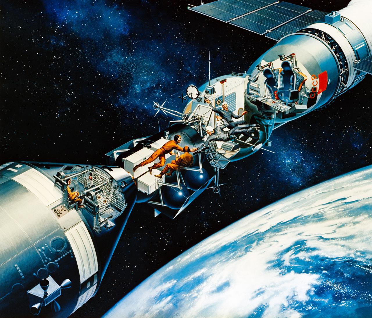
S75-27290 (April 1975) --- An artist?s concept illustrating a cutaway view of the docked Apollo and Soyuz spacecraft in Earth orbit. This scene depicts the moment the two international crews meet in space for the first time. Two of the three American crewmen are in the Docking Module. The two Soviet crewmen are in the Soyuz spacecraft?s Orbital Module. The two crew commanders are shaking hands through the hatchway. The third American crewman is in the Apollo Command Module. During the joint U.S.-USSR Apollo-Soyuz Test Project mission, which is scheduled for July 1975, the American and Soviet crews will visit one another?s spacecraft while the Soyuz and Apollo are docked for a maximum period of two days. The mission is designed to test equipment and techniques that will establish international crew rescue capability in space, as well as permit future cooperative scientific missions. The artwork is by Davis Meltzer.
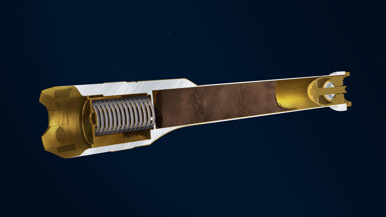
This illustration depicts the interior of a sample tube being carried aboard the Mars 2020 Perseverance rover. About the size and shape of a standard lab test tube, the 43 sample tubes headed to Mars must be lightweight, hardy enough to survive the demands of the round trip, and so clean that future scientists will be confident that what they are analyzing is 100% Mars, without Earthly contaminants. Cutaway Plunger: Works in concert with the spring to release (retract) or activate (extend) the two exterior-mounted ball locks. Springs: Along with the plunger, acts to release or activate the ball locks. Payload Cavity: Also known as the bore, is the area in the tube where cores of Martian rock and samples of regolith will be stored. Titanium Nitride Coating: The specialized surface treatment resists contamination. Hermetic Seal: This mechanically-activated plug is designed to ensure that no contaminants can get into the sample tube and that nothing from inside the tube can get out. https://photojournal.jpl.nasa.gov/catalog/PIA24307
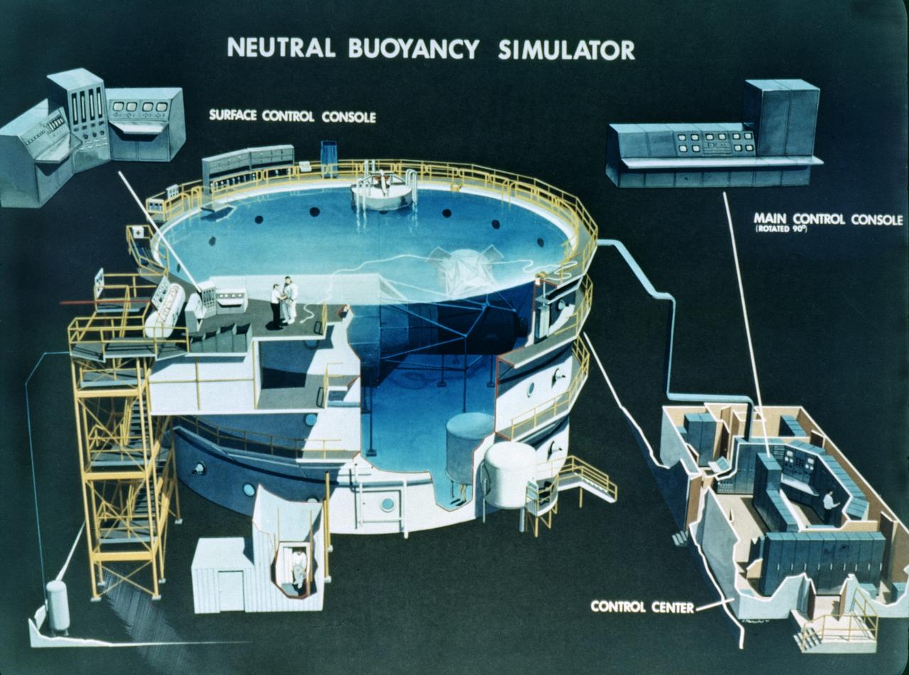
This is a cutaway illustration of the Neutral Buoyancy Simulator (NBS) at the Marshall Space Flight Center (MSFC ). The MSFC NBS provided an excellent environment for testing hardware to examine how it would operate in space and for evaluating techniques for space construction and spacecraft servicing. Here, engineers, designers, and astronauts performed various tests to develop basic concepts, preliminary designs, final designs, and crew procedures. The NBS was constructed of welded steel with polyester-resin coating. The water tank was 75-feet (22.9- meters) in diameter, 40-feet (12.2-meters) deep, and held 1.32 million gallons of water. Since it opened for operation in 1968, the NBS had supported a number of successful space missions, such as the Skylab, Solar Maximum Mission Satellite, Marned Maneuvering Unit, Experimental Assembly of Structures in Extravehicular Activity/Assembly Concept for Construction of Erectable Space Structures (EASE/ACCESS), the Hubble Space Telescope, and the Space Station. The function of the MSFC NBS was moved to the larger simulator at the Johnson Space Center and is no longer operational.
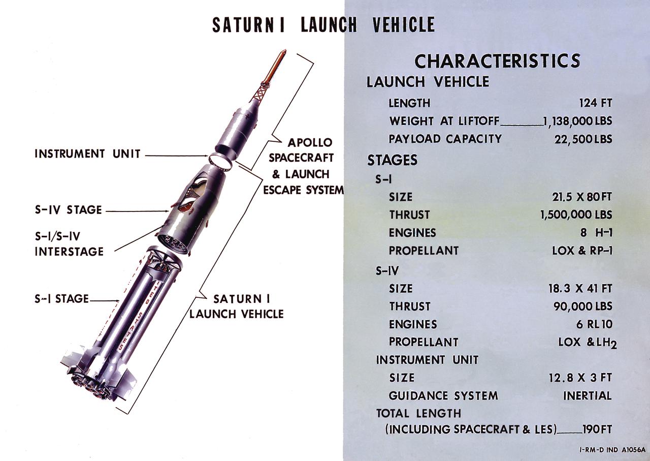
A cutaway illustration of Saturn I launch vehicle characteristics: The Saturn I, first of the Saturn launch vehicles' family, is a two-stage vehicle with a low-earth-orbit payload capability of approximately 25,000 pounds. The research and development program was plarned in two phases or blocks; one for first stage development (Block I) and the second for first and second stage development (Block II). The S-I (first) stage consisted of a cluster of nine propellant tanks and eight H-1 engines built by Rocketdyne, yeilding a total thrust of 1,500,000 pounds. The second stage identified as S-IV, was designed as a single cylinder with a common bulkhead separating the liquid oxygen from the liquid hydrogen. Propulsion was provided by six RL-10 engines built by Pratt Whitney, capable of producing a combined thrust of 90,000 pounds. Of the 10 Saturn I's planned, the first eight were designed and built at the Marshall Space Flight Center. The remaining two were built by the Chrysler Corporation.
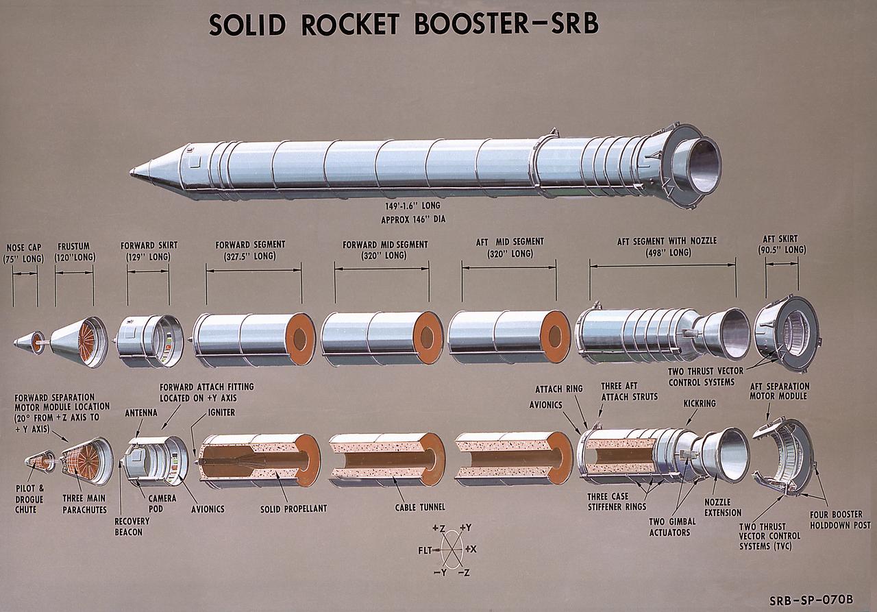
This illustration is a cutaway of the solid rocket booster (SRB) sections with callouts. The Shuttle's two SRB's are the largest solids ever built and the first designed for refurbishment and reuse. Standing nearly 150-feet high, the twin boosters provide the majority of thrust for the first two minutes of flight, about 5.8 million pounds, augmenting the Shuttle's main propulsion system during liftoff. The major design drivers for the solid rocket motors (SRM's) were high thrust and reuse. The desired thrust was achieved by using state-of-the-art solid propellant and by using a long cylindrical motor with a specific core design that allows the propellant to burn in a carefully controlled marner. At burnout, the boosters separate from the external tank and drop by parachute to the ocean for recovery and subsequent refurbishment. The boosters are designed to survive water impact at almost 60 miles per hour, maintain flotation with minimal damage, and preclude corrosion of the hardware exposed to the harsh seawater environment. Under the project management of the Marshall Space Flight Center, the SRB's are assembled and refurbished by the United Space Boosters. The SRM's are provided by the Morton Thiokol Corporation.

This is a cutaway illustration of the Space Shuttle external tank (ET) with callouts. The giant cylinder, higher than a 15-story building, with a length of 154-feet (47-meters) and a diameter of 27.5-feet (8.4-meters), is the largest single piece of the Space Shuttle. During launch, the ET also acts as a backbone for the orbiter and solid rocket boosters. Separate pressurized tank sections within the external tank hold the liquid hydrogen fuel and liquid oxygen oxidizer for the Shuttle's three main engines. During launch, the ET feeds the fuel under pressure through 17-inch (43.2-centimeter) ducts that branch off into smaller lines that feed directly into the main engines. The main engines consume 64,000 gallons (242,260 liters) of fuel each minute. Machined from aluminum alloys, the Space Shuttle's external tank is currently the only part of the launch vehicle that is not reused. After its 526,000-gallons (1,991,071 liters) of propellants are consumed during the first 8.5-minutes of flight, it is jettisoned from the orbiter and breaks up in the upper atmosphere, its pieces falling into remote ocean waters. The Marshall Space Flight Center was responsible for developing the ET.
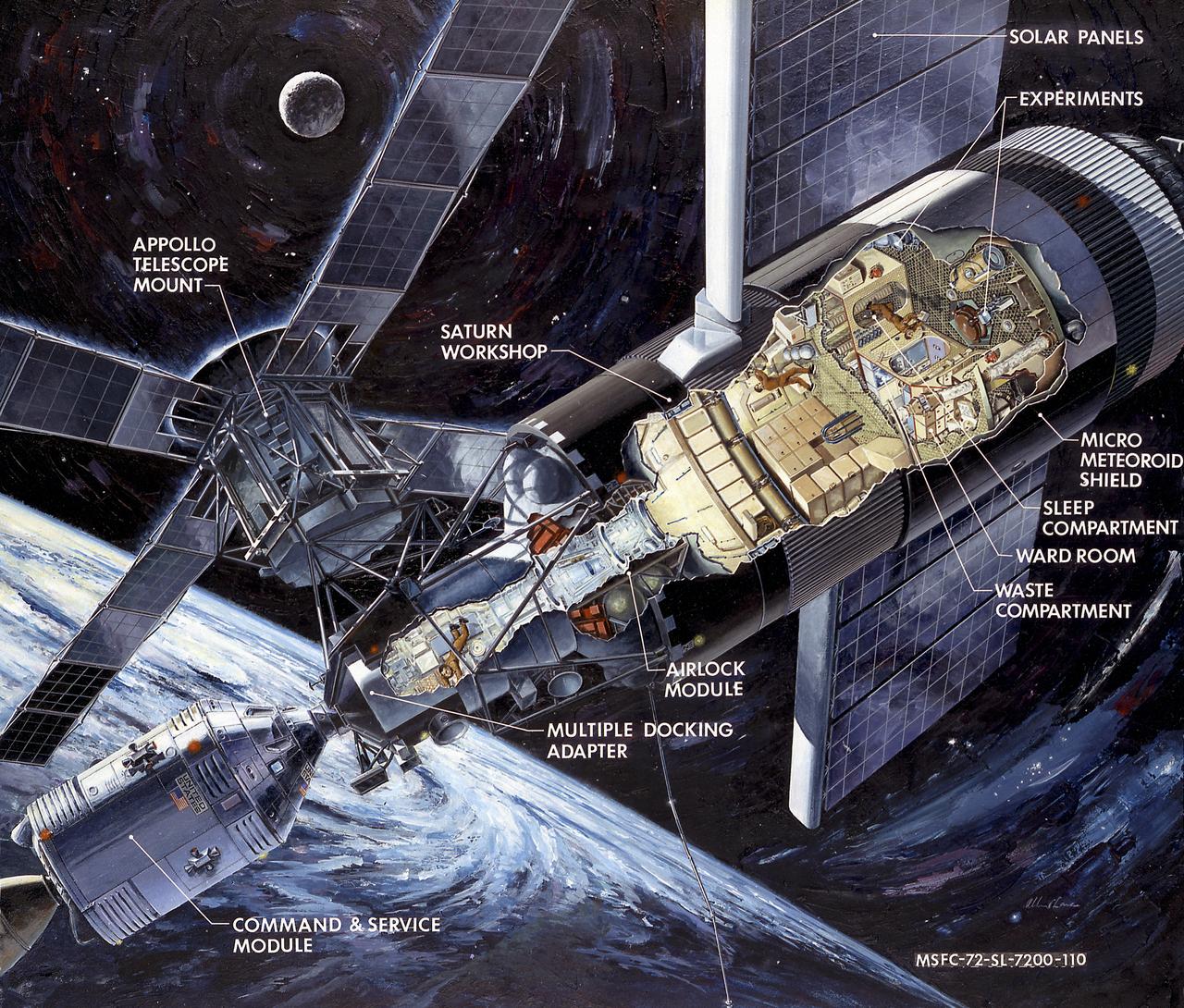
This artist's concept is a cutaway illustration of the Skylab with the Command/Service Module being docked to the Multiple Docking Adapter. In an early effort to extend the use of Apollo for further applications, NASA established the Apollo Applications Program (AAP) in August of 1965. The AAP was to include long duration Earth orbital missions during which astronauts would carry out scientific, technological, and engineering experiments in space by utilizing modified Saturn launch vehicles and the Apollo spacecraft. Established in 1970, the Skylab Program was the forerurner of the AAP. The goals of the Skylab were to enrich our scientific knowledge of the Earth, the Sun, the stars, and cosmic space; to study the effects of weightlessness on living organisms, including man; to study the effects of the processing and manufacturing of materials utilizing the absence of gravity; and to conduct Earth resource observations. The Skylab also conducted 19 selected experiments submitted by high school students. Skylab's 3 different 3-man crews spent up to 84 days in Earth orbit. The Marshall Space Flight Center (MSFC) had responsibility for developing and integrating most of the major components of the Skylab: the Orbital Workshop (OWS), Airlock Module (AM), Multiple Docking Adapter (MDA), Apollo Telescope Mount (ATM), Payload Shroud (PS), and most of the experiments. MSFC was also responsible for providing the Saturn IB launch vehicles for three Apollo spacecraft and crews and a Saturn V launch vehicle for the Skylab.
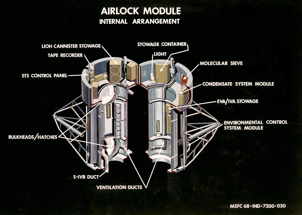
This illustration is a cutaway view of the internal arrangement of the Airlock Module (AM). The aft end of the Docking Adapter mated to the AM, and served as the environmental, electrical, and communications control center. The docking adapter also contained the port through which the astronauts exited to perform extravehicular activity. The AM contained a turnel section through which Skylab crewmen could move between the workshop and the forward end of the airlock. It was encircled, for part of its length, at its aft end by the fixed Airlock Shroud (FAS), that had the same diameter as the workshop (22 feet) and was attached to the workshop's forward end. High pressure containers for oxygen and nitrogen providing Skylab's atmosphere, were mounted in the annular space between the outside of the tunnel and the inside of the shroud. The forward end of the FAS was the base on which the tubular structure supporting the solar observatory was mounted. Many of the supplies, and most of the control systems for Skylab were located in the AM; this module could well be the "utility center" of the Skylab cluster. McDonnell Douglas fabricated the module with close Marshall Space Flight Center's involvement in design, development, and test activities.
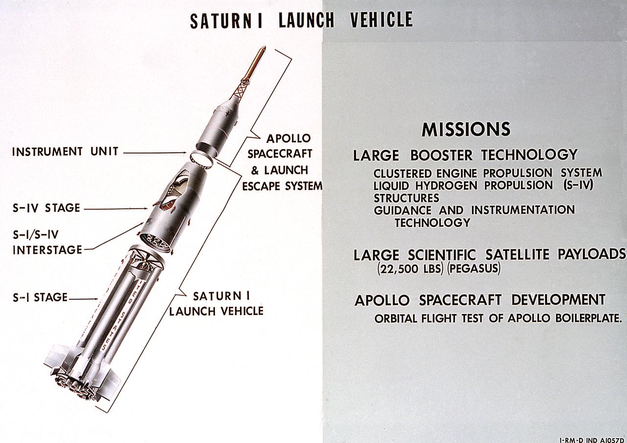
A cutaway illustration of Saturn 1 launch vehicle mission. The Saturn I, first of the Saturn launch vehicles' family, is a two-stage vehicle with a low-earth-orbit payload capability of approximately 25,000 pounds. The research and development program was plarned in two phases or blocks; one for first stage development (Block I) and the second for first and second stage development (Block II). The S-I (first) stage consisted of a cluster of nine propellant tanks and eight H-1 engines built by Rocketdyne, yeilding a total thrust of 1,500,000 pounds. The second stage of Saturn I, identified as S-IV, was designed as a single cylinder with a common bulkhead separating the liquid oxygen from the liquid hydrogen. Propulsion was provided by six RL-10 engines built by Pratt Whitney, capable of producing a combined thrust of 90,000 pounds. Of the 10 Saturn I's planned, the first eight were designed and built at the Marshall Space Flight Center. The remaining two were built by the Chrysler Corporation.
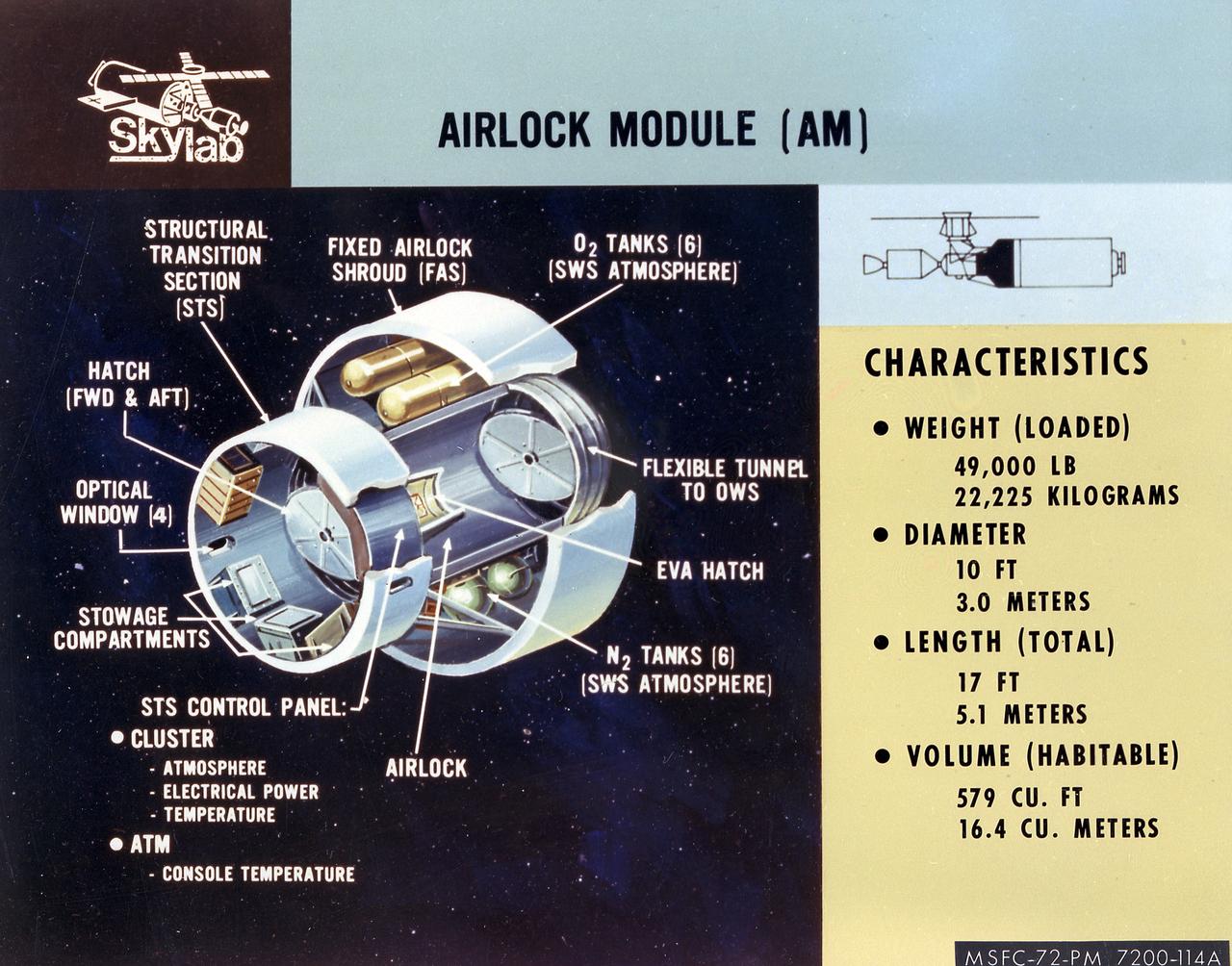
This artist's concept is a cutaway illustration of the Skylab Airlock Module and its characteristics. The aft end of the Docking Adapter mated to the Airlock Module (AM), and served as the environmental, electrical, and communications control center. The docking adapter also contained the port through which the astronauts exited to perform extravehicular activity. The AM contained a turnel section through which Skylab crewmen could move between the workshop and the forward end of the airlock. It was encircled, for part of its length, at its aft end by the fixed Airlock Shroud (FAS), that had the same diameter as the workshop (22 feet) and was attached to the workshop's forward end. High pressure containers for oxygen and nitrogen providing Skylab's atmosphere, were mounted in the annular space between the outside of the tunnel and the inside of the shroud. The forward end of the FAS was the base on which the tubular structure supporting the solar observatory was mounted. Many of the supplies, and most of the control systems for Skylab were located in the AM; this module could well be the "utility center" of the Skylab cluster. McDonnell Douglas fabricated the module with close Marshall Space Flight Center's involvement in design, development, and test activities.
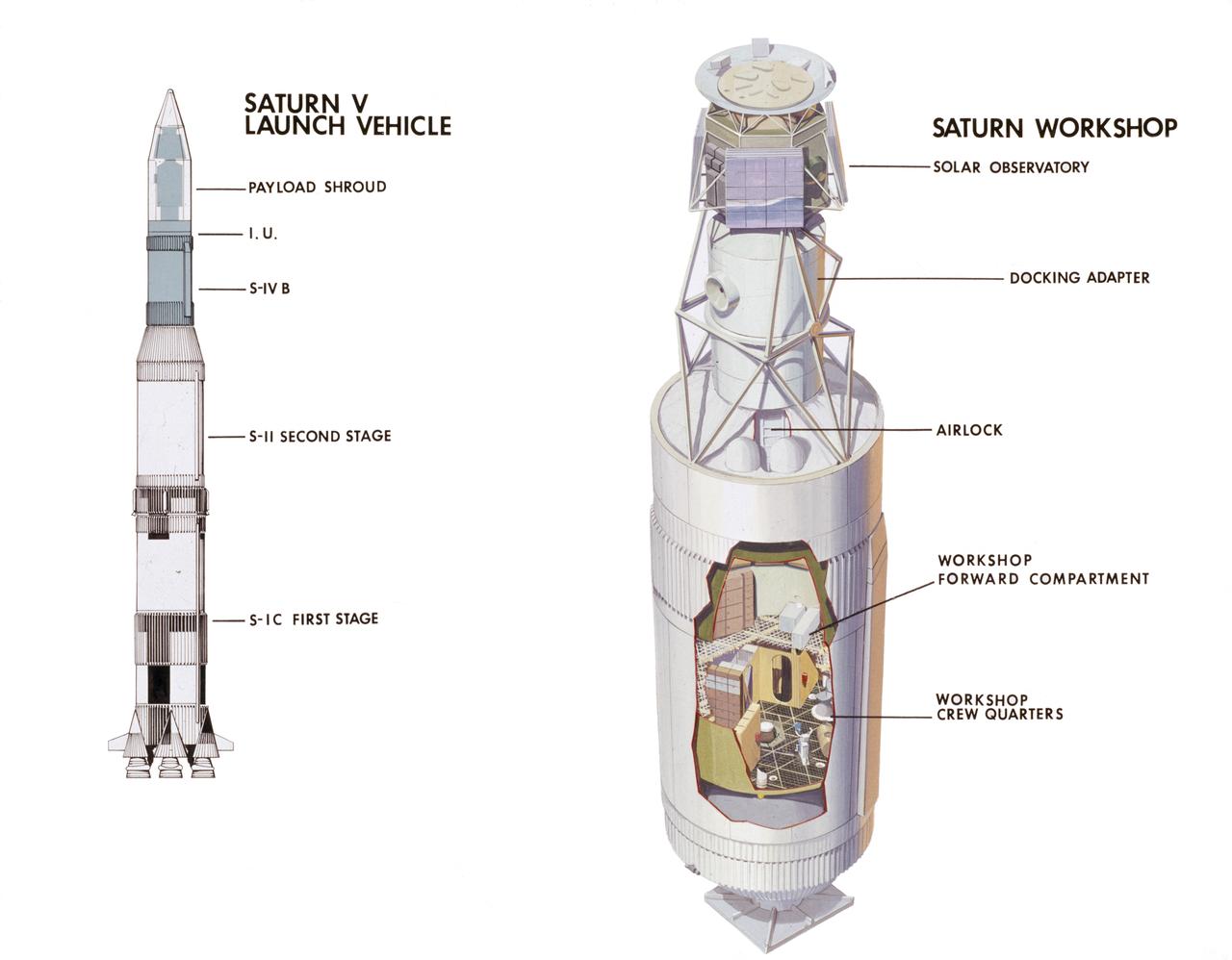
This cutaway drawing illustrates major Skylab components in launch configuration on top of the Saturn V. In an early effort to extend the use of Apollo for further applications, NASA established the Apollo Applications Program (AAP) in August of 1965. The AAP was to include long duration Earth orbital missions during which astronauts would carry out scientific, technological, and engineering experiments in space by utilizing modified Saturn launch vehicles and the Apollo spacecraft. Established in 1970, the Skylab Program was the forerurner of the AAP. The goals of the Skylab were to enrich our scientific knowledge of the Earth, the Sun, the stars, and cosmic space; to study the effects of weightlessness on living organisms, including man; to study the effects of the processing and manufacturing of materials utilizing the absence of gravity; and to conduct Earth resource observations. The Skylab also conducted 19 selected experiments submitted by high school students. Skylab's 3 different 3-man crews spent up to 84 days in Earth orbit. The Marshall Space Flight Center (MSFC) had responsibility for developing and integrating most of the major components of the Skylab: the Orbital Workshop (OWS), Airlock Module (AM), Multiple Docking Adapter (MDA), Apollo Telescope Mount (ATM), Payload Shroud (PS), and most of the experiments. MSFC was also responsible for providing the Saturn IB launch vehicles for three Apollo spacecraft and crews and a Saturn V launch vehicle for the Skylab.
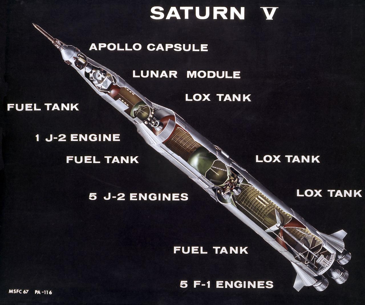
This is a cutaway illustration of the Saturn V launch vehicle with callouts of the major components. The Saturn V is the largest and most powerful launch vehicle developed in the United States. It was a three stage rocket, 363 feet in height, used for sending American astronauts to the moon and for placing the Skylab in Earth orbit. The Saturn V was designed to perform Earth orbital missions through the use of the first two stages, while all three stages were used for lunar expeditions. The S-IC stage (first stage) was powered by five F- engines, which burned kerosene and liquid oxygen to produce more than 7,500,000 pounds of thrust. The S-II (second) stage was powered by five J-2 engines, that burned liquid hydrogen and liquid oxygen and produced 1,150,000 pounds thrust. The S-IVB (third) stage used one J-2 engine, producing 230,000 pounds of thrust, with a re-start capability. The Marshall Space Flight Center and its contractors designed, developed, and assembled the Saturn V launch vehicle stages.
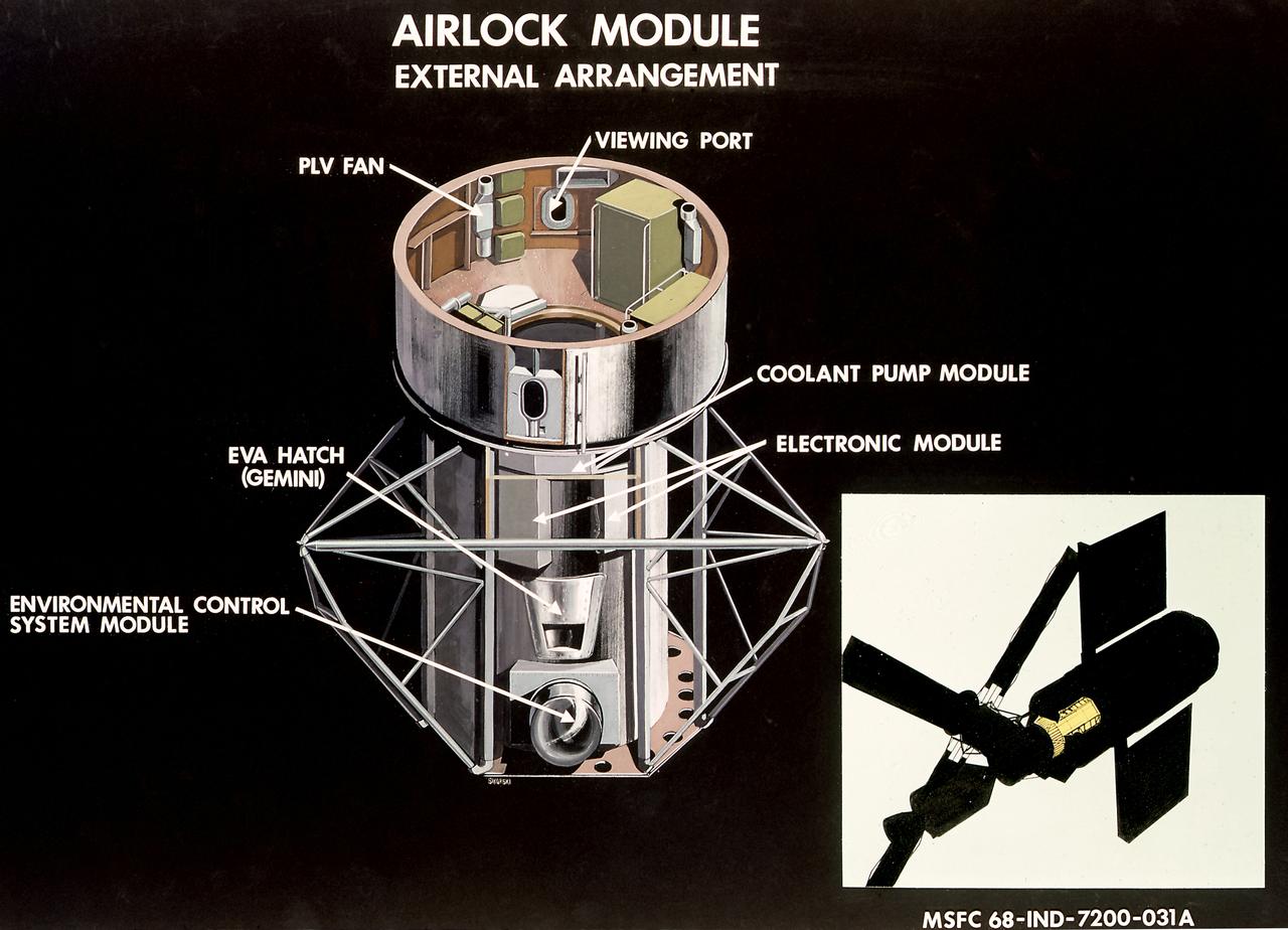
This illustration is a cutaway view of the external arrangement of the Airlock Module (AM). The aft end of the Docking Adapter mated to the AM, and served as the environmental, electrical, and communications control center. The docking adapter also contained the port through which the astronauts exited to perform extravehicular activity. The AM contained a turnel section through which Skylab crewmen could move between the workshop and the forward end of the airlock. It was encircled, for part of its length, at its aft end by the fixed Airlock Shroud (FAS), that had the same diameter as the workshop (22 feet) and was attached to the workshop's forward end. High pressure containers for oxygen and nitrogen providing Skylab's atmosphere, were mounted in the annular space between the outside of the tunnel and the inside of the shroud. The forward end of the FAS was the base on which the tubular structure supporting the solar observatory was mounted. Many of the supplies, and most of the control systems for Skylab were located in the AM; this module could well be the "utility center" of the Skylab cluster. McDonnell Douglas fabricated the module with close Marshall Space Flight Center's involvement in design, development, and test activities.

This illustration is an orbiter cutaway view with callouts. The orbiter is both the brains and heart of the Space Transportation System (STS). About the same size and weight as a DC-9 aircraft, the orbiter contains the pressurized crew compartment (which can normally carry up to seven crew members), the huge cargo bay, and the three main engines mounted on its aft end. There are three levels to the crew cabin. Uppermost is the flight deck where the commander and the pilot control the mission. The middeck is where the gallery, toilet, sleep stations, and storage and experiment lockers are found for the basic needs of weightless daily living. Also located in the middeck is the airlock hatch into the cargo bay and space beyond. It is through this hatch and airlock that astronauts go to don their spacesuits and marned maneuvering units in preparation for extravehicular activities, more popularly known as spacewalks. The Space Shuttle's cargo bay is adaptable to hundreds of tasks. Large enough to accommodate a tour bus (60 x 15 feet or 18.3 x 4.6 meters), the cargo bay carries satellites, spacecraft, and spacelab scientific laboratories to and from Earth orbit. It is also a work station for astronauts to repair satellites, a foundation from which to erect space structures, and a hold for retrieved satellites to be returned to Earth. Thermal tile insulation and blankets (also known as the thermal protection system or TPS) cover the underbelly, bottom of the wings, and other heat-bearing surfaces of the orbiter to protect it during its fiery reentry into the Earth's atmosphere. The Shuttle's 24,000 individual tiles are made primarily of pure-sand silicate fibers, mixed with a ceramic binder. The solid rocket boosters (SRB's) are designed as an in-house Marshall Space Flight Center project, with United Space Boosters as the assembly and refurbishment contractor. The solid rocket motor (SRM) is provided by the Morton Thiokol Corporation.