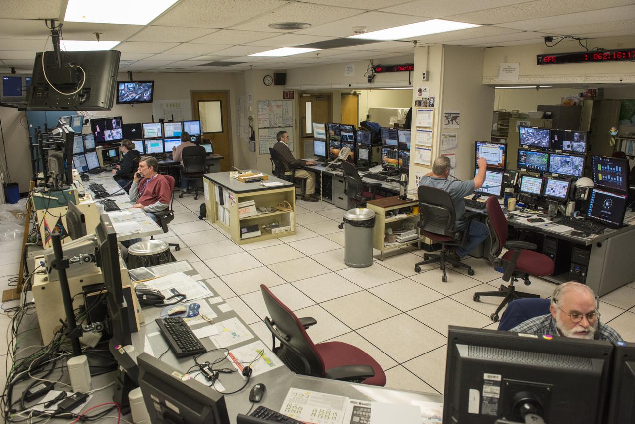
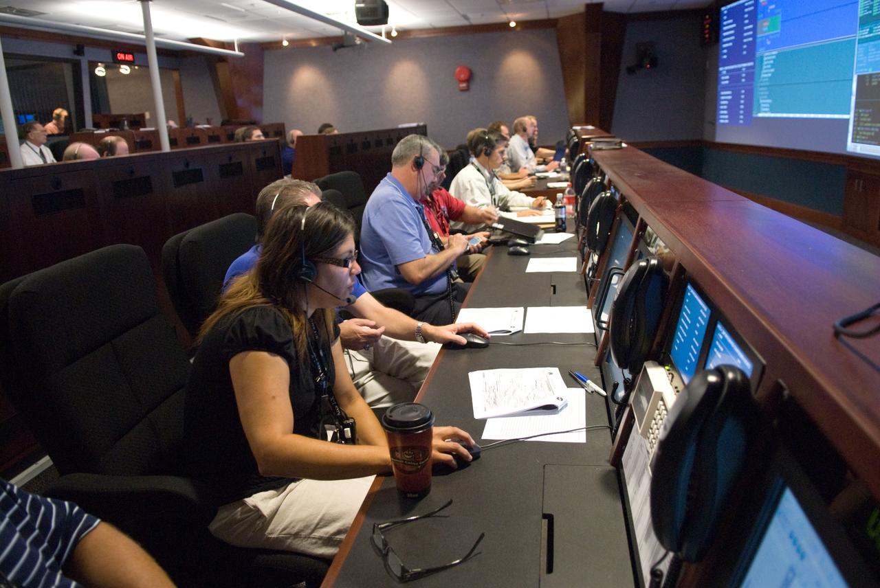
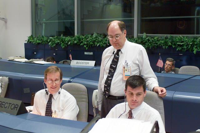
DATA OPERATIONS CONTROL ROOM TEAM MEMBERS TAKE ALL SCIENCE DATA FROM THE INTERNATIONAL SPACE STATION, AND DISTRIBUTE IT TO THE PAYLOAD OPERATIONS INTEGRATION CENTER AND SCIENTISTS ALL OVER THE WORLD WHO HAVE EXPERIMENTS ON THE ORBITING LABORATORY.
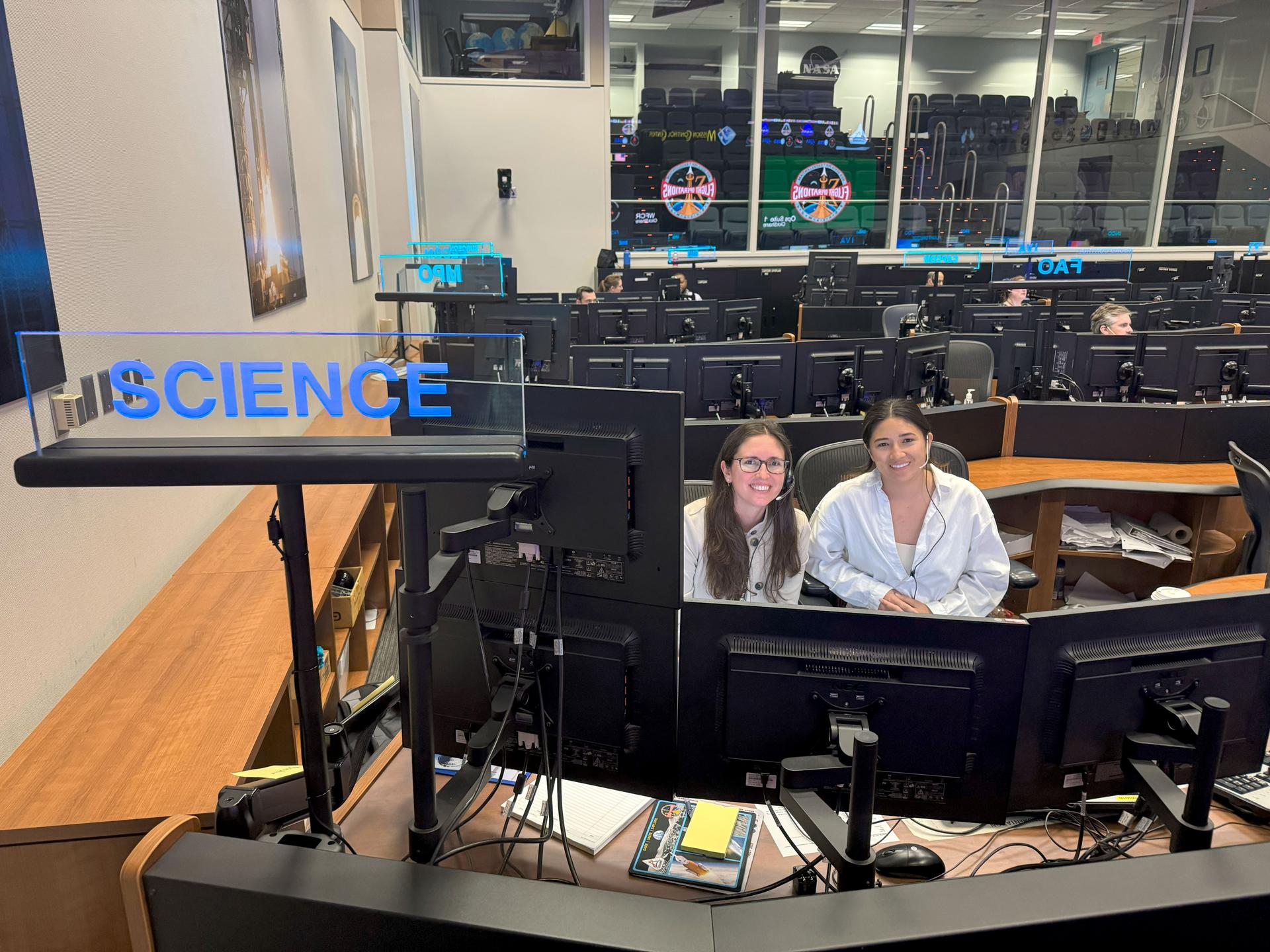
jsc2025e067512 --- Artemis II science officers Kelsey Young, left, and Angela Garcia sit at the SCIENCE console during a training simulation in the White Flight Control Room of the Mission Control Center at NASA's Johnson Space Center in Houston. Artemis II will test mission science operations and integration into flight control. Lessons learned during Artemis II science operations will pave the way for lunar science operations for future Artemis missions. A team of experts will staff the Science Evaluation Room (SER) at Johnson, providing lunar scientific expertise, data analysis, and strategic guidance in real-time to the science officer and the rest of Mission Control.
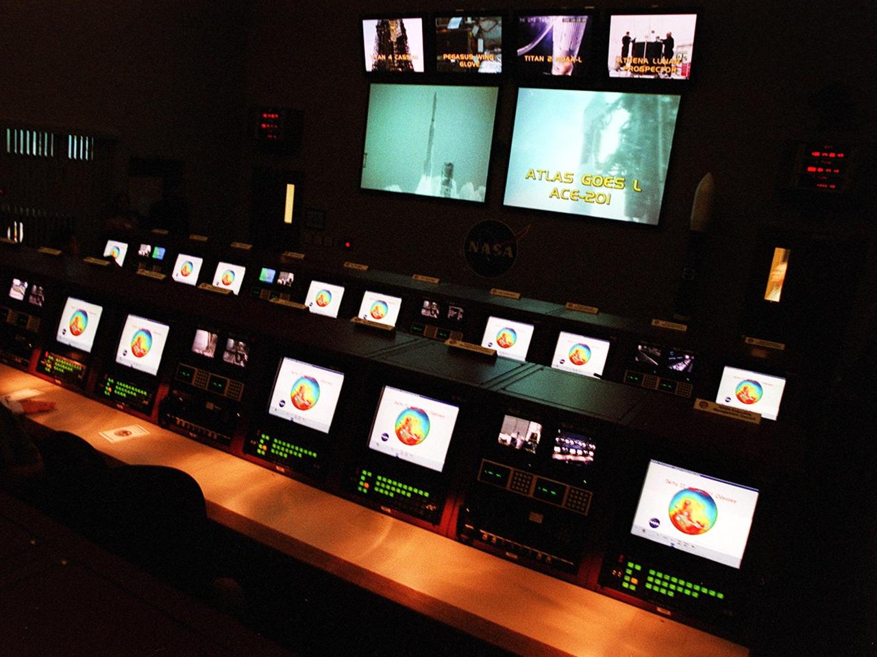
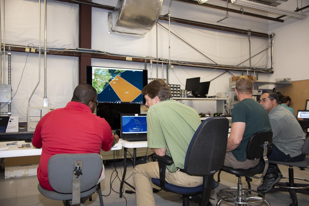
State-of-the-art displays shown here provide enhanced capability to engineers in the upgraded Launch Vehicle Data Center in Hangar AE, Cape Canaveral Air Force Station, Fla. The new facility’s three individual control rooms replace a single LVDC control room in use since the mid-1970s. Developed by NASA-KSC to support multiple test operations in parallel or a single large launch operation, the new LVDC allows up to 100 launch vehicle engineers to monitor the voice, data and video systems that support the checkout and launch of an expendable vehicle
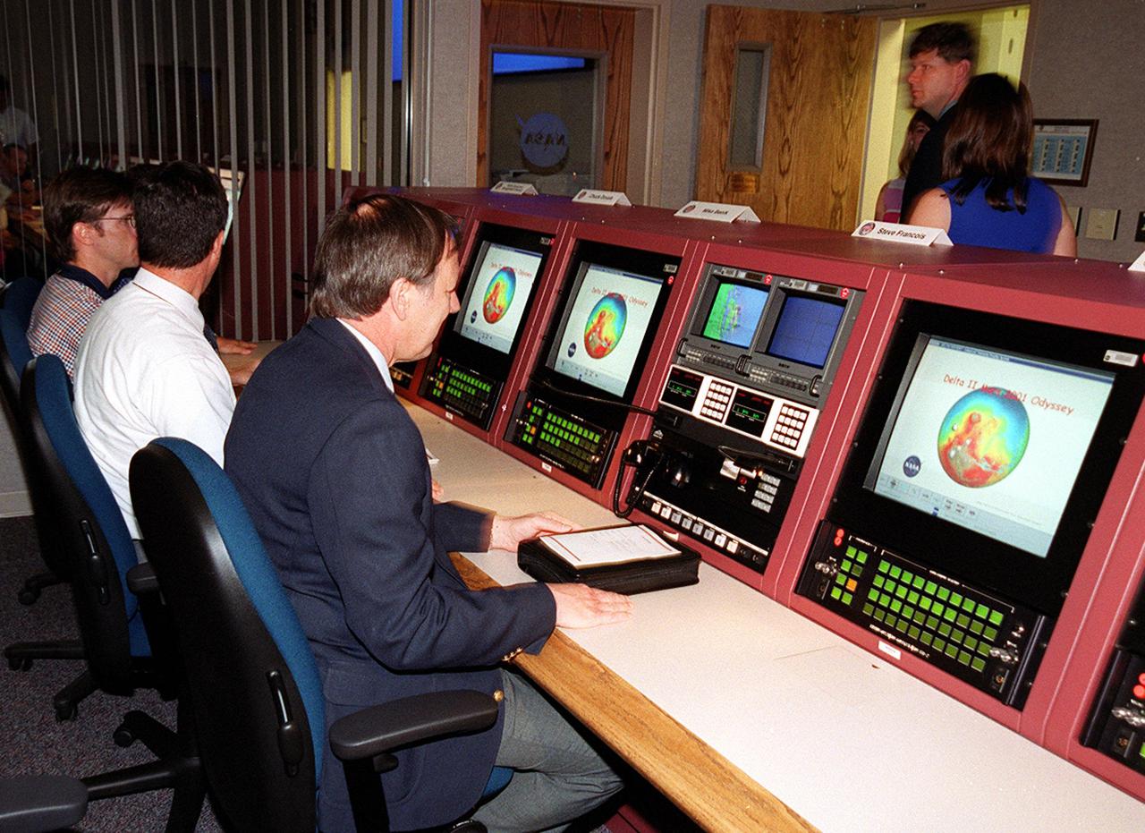
At the dedication of the upgraded Launch Vehicle Data Center in Hangar AE, Cape Canaveral Air Force Station, Fla., attendees got a close look at the new consoles. Seated on the right is Steve Francois, program manager, Expendable Vehicles and Payload Carriers. The new facility’s three individual control rooms replace a single LVDC control room in use since the mid-1970s. Developed by NASA-KSC to support multiple test operations in parallel or a single large launch operation, the new LVDC allows up to 100 launch vehicle engineers to monitor the voice, data and video systems that support the checkout and launch of an expendable vehicle
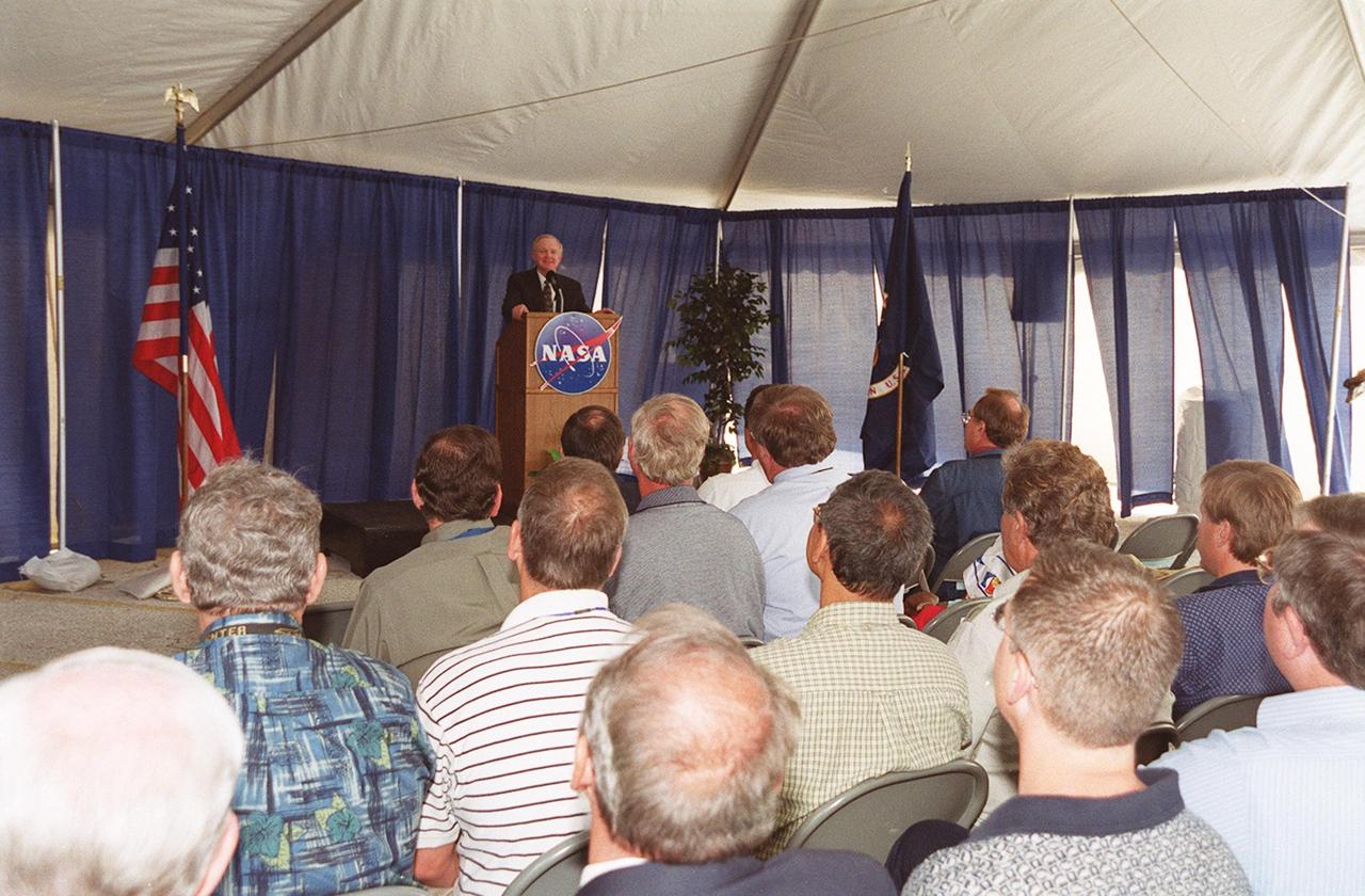
Center Director Roy Bridges addresses attendees at the dedication of the upgraded Launch Vehicle Data Center in Hangar AE, Cape Canaveral Air Force Station, Fla. The new facility’s three individual control rooms replace a single LVDC control room in use since the mid-1970s. Developed by NASA-KSC to support multiple test operations in parallel or a single large launch operation, the new LVDC allows up to 100 launch vehicle engineers to monitor the voice, data and video systems that support the checkout and launch of an expendable vehicle
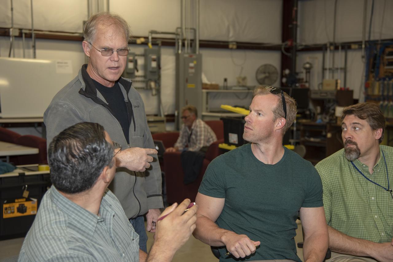
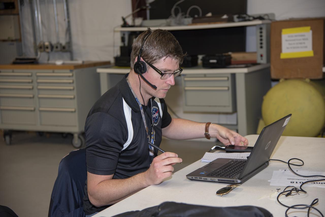
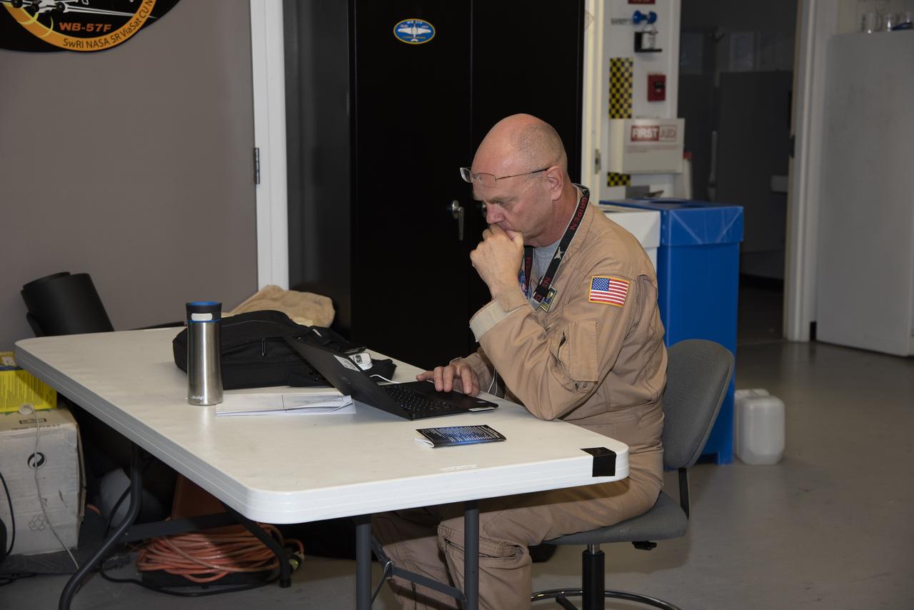
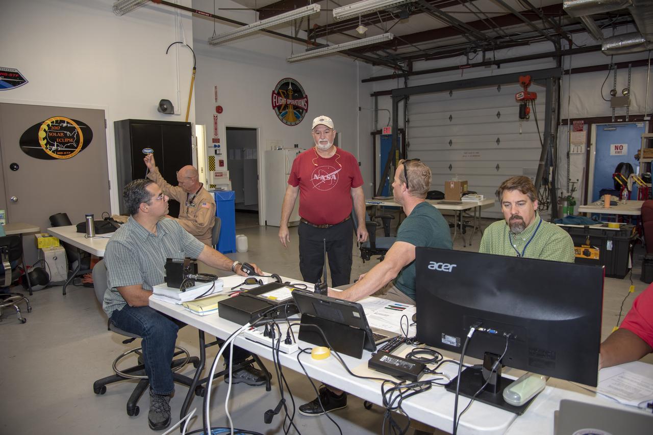
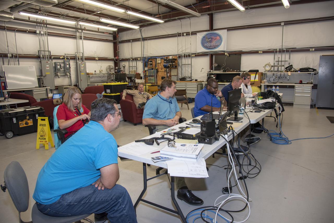
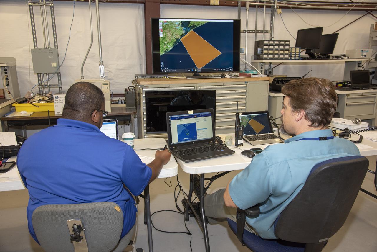
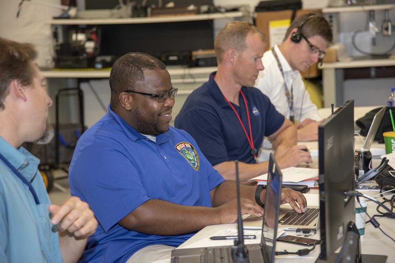
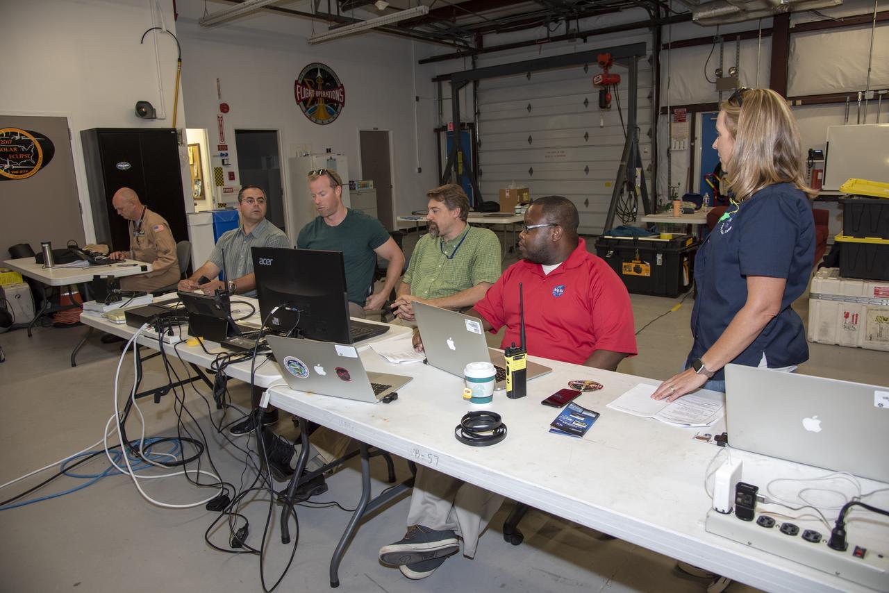
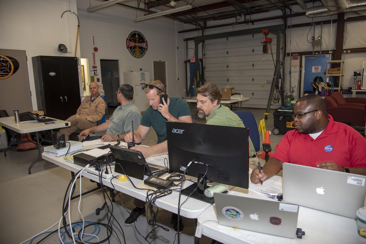
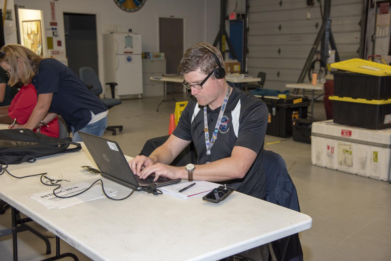
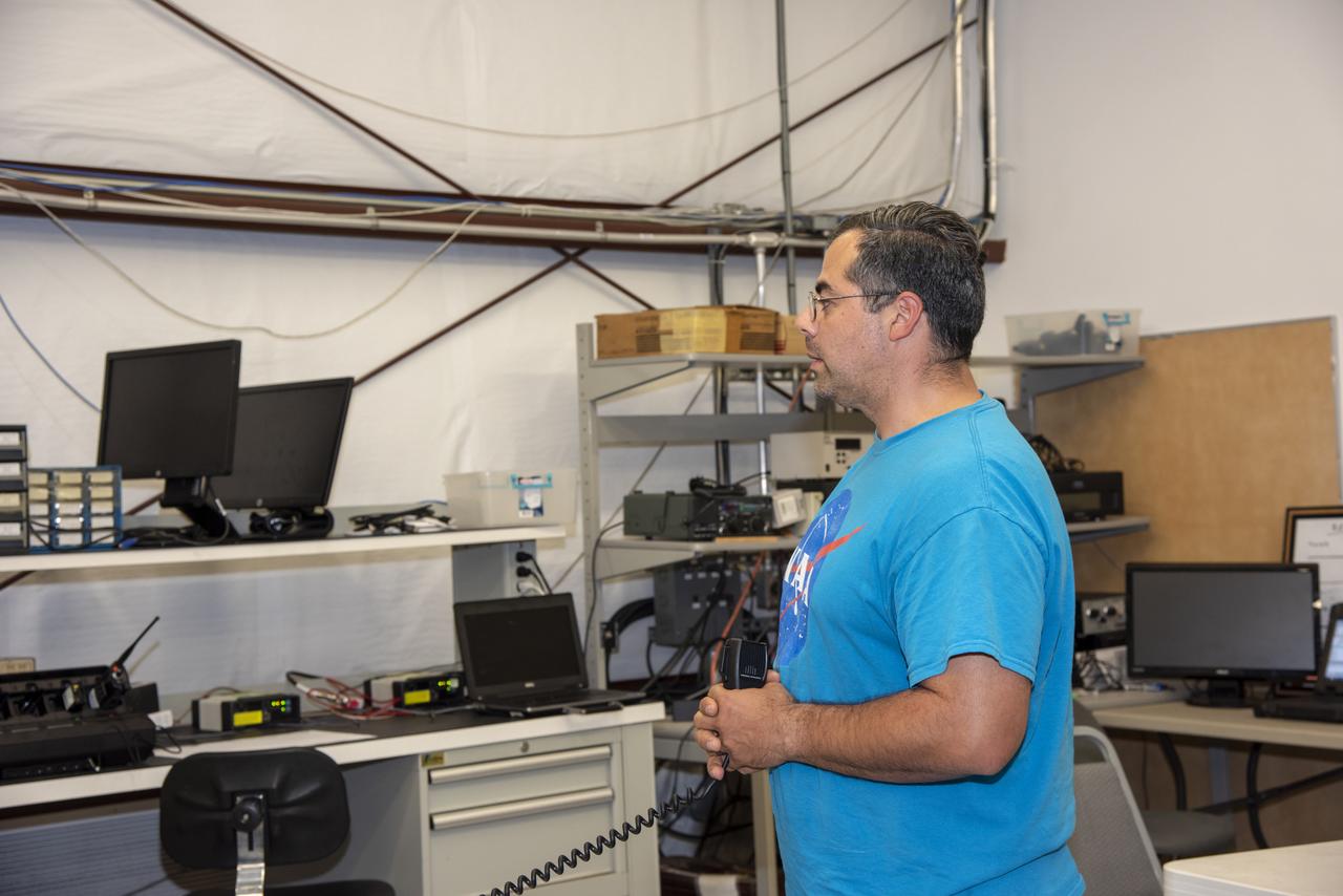
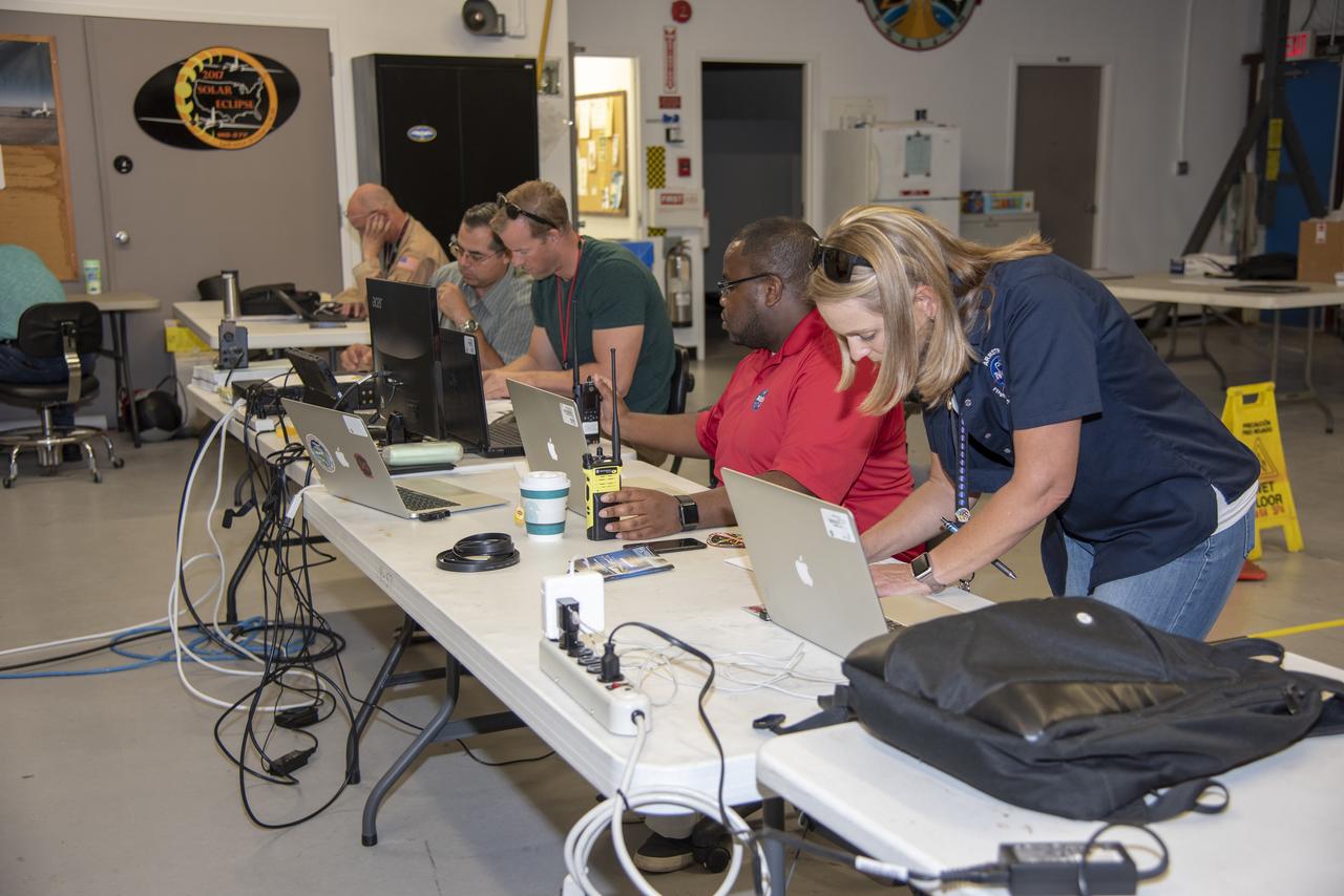
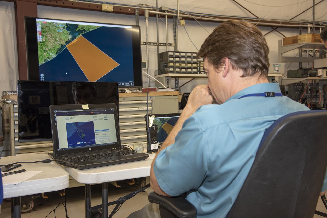
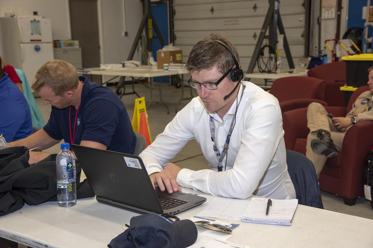
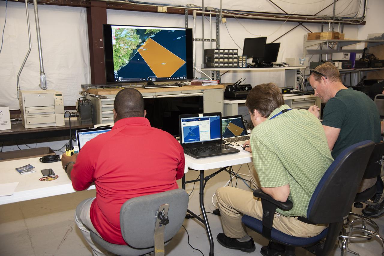
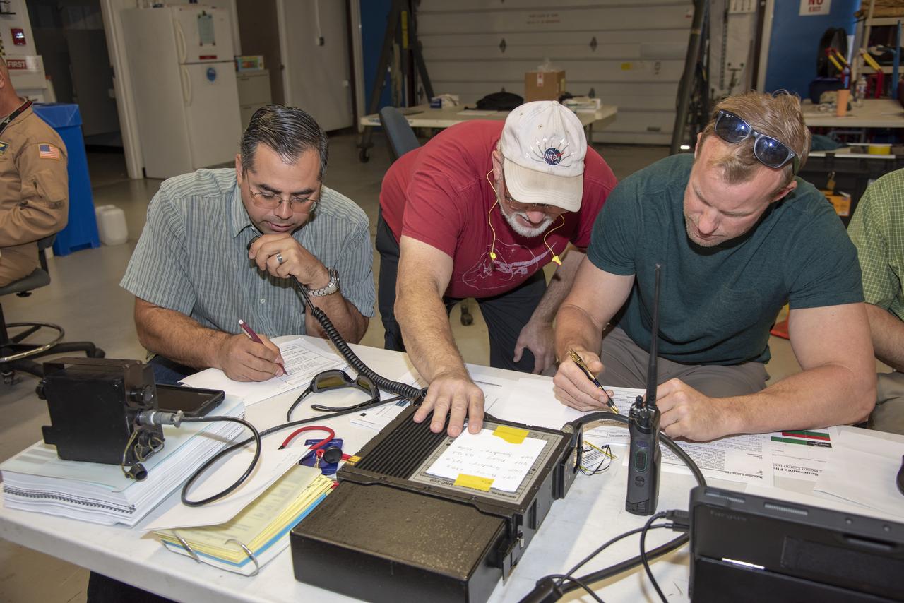
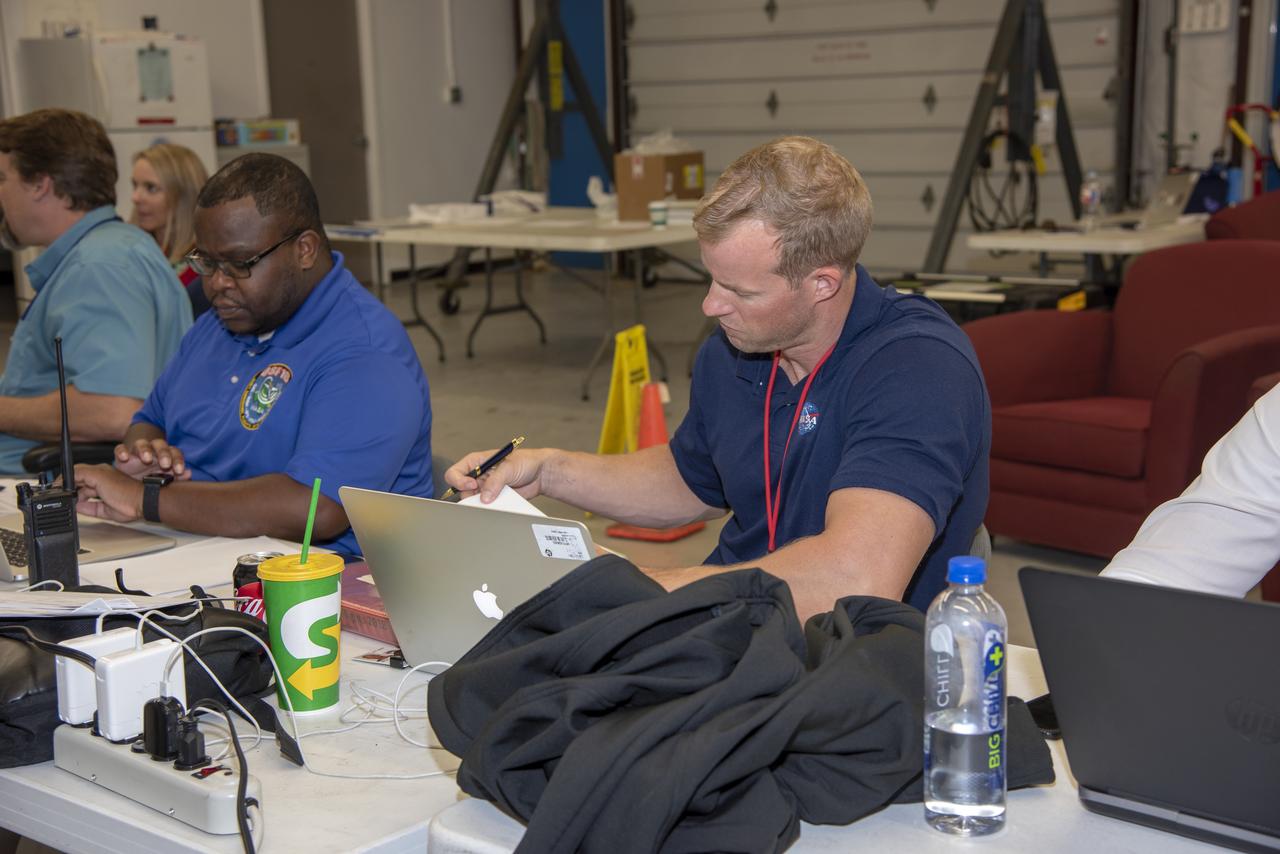
NASA mission controllers, engineers, pilots and communications specialists in the mission control room monitor the supersonic research flight off the coast of Galveston, as part of the QSF18 flight series. The flight operations crew tracks the status of the flights, maintains communications with the aircraft, communicates with U.S. Coast Guard, and coordinates community feedback data.

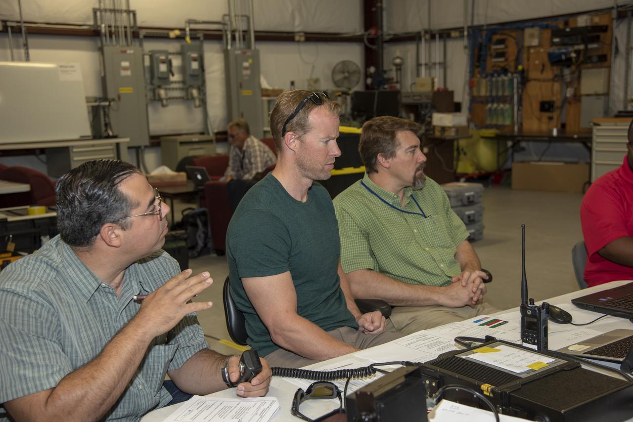
NASA mission controllers, engineers, pilots and communications specialists in the mission control room monitor the supersonic research flight off the coast of Galveston, as part of the QSF18 flight series. The flight operations crew tracks the status of the flights, maintains communications with the aircraft, communicates with U.S. Coast Guard, and coordinates community feedback data.
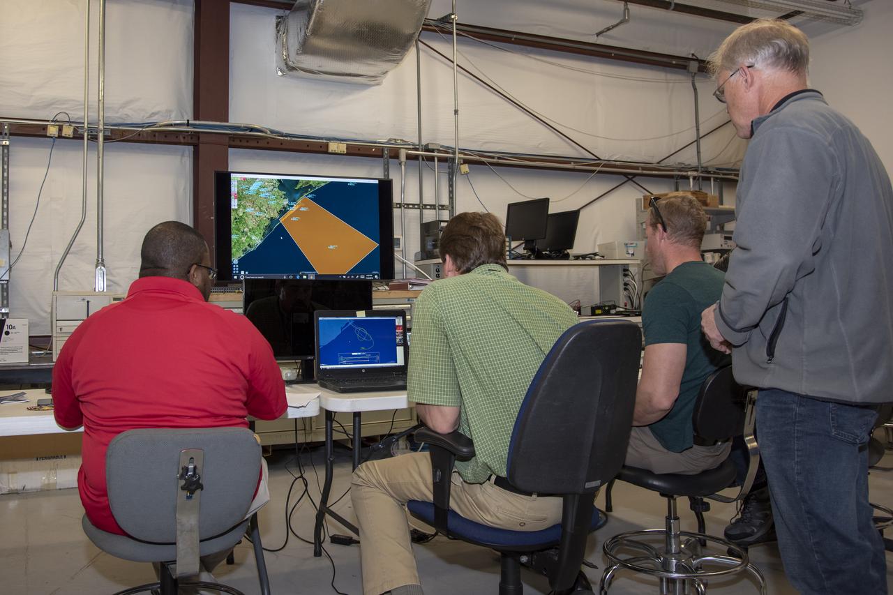
NASA mission controllers, engineers, pilots and communications specialists in the mission control room monitor the supersonic research flight off the coast of Galveston, as part of the QSF18 flight series. The flight operations crew tracks the status of the flights, maintains communications with the aircraft, communicates with U.S. Coast Guard, and coordinates community feedback data.
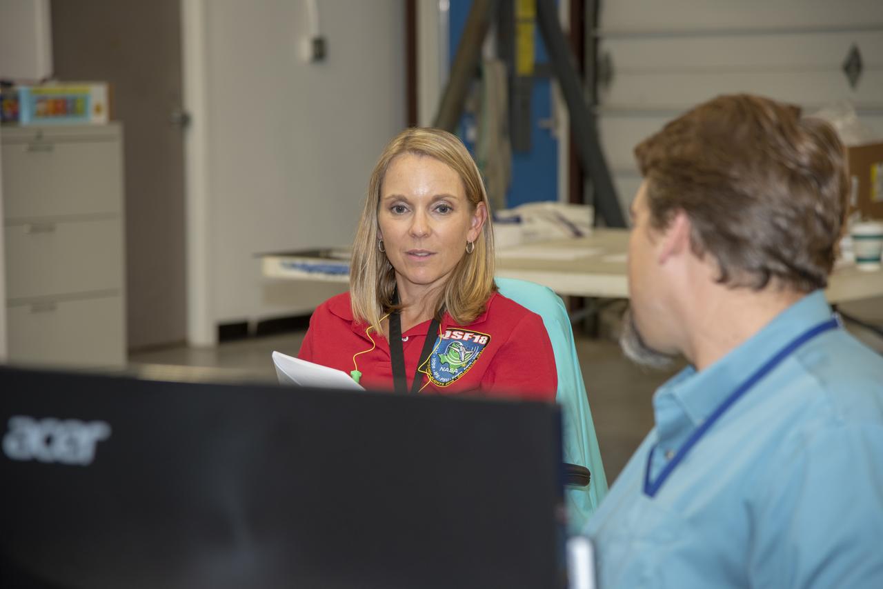
NASA mission controllers, engineers, pilots and communications specialists in the mission control room monitor the supersonic research flight off the coast of Galveston, as part of the QSF18 flight series. The flight operations crew tracks the status of the flights, maintains communications with the aircraft, communicates with U.S. Coast Guard, and coordinates community feedback data.
NASA mission controllers, engineers, pilots and communications specialists in the mission control room monitor the supersonic research flight off the coast of Galveston, as part of the QSF18 flight series. The flight operations crew tracks the status of the flights, maintains communications with the aircraft, communicates with U.S. Coast Guard, and coordinates community feedback data.
NASA mission controllers, engineers, pilots and communications specialists in the mission control room monitor the supersonic research flight off the coast of Galveston, as part of the QSF18 flight series. The flight operations crew tracks the status of the flights, maintains communications with the aircraft, communicates with U.S. Coast Guard, and coordinates community feedback data.
NASA mission controllers, engineers, pilots and communications specialists in the mission control room monitor the supersonic research flight off the coast of Galveston, as part of the QSF18 flight series. The flight operations crew tracks the status of the flights, maintains communications with the aircraft, communicates with U.S. Coast Guard, and coordinates community feedback data.
NASA mission controllers, engineers, pilots and communications specialists in the mission control room monitor the supersonic research flight off the coast of Galveston, as part of the QSF18 flight series. The flight operations crew tracks the status of the flights, maintains communications with the aircraft, communicates with U.S. Coast Guard, and coordinates community feedback data.
NASA mission controllers, engineers, pilots and communications specialists in the mission control room monitor the supersonic research flight off the coast of Galveston, as part of the QSF18 flight series. The flight operations crew tracks the status of the flights, maintains communications with the aircraft, communicates with U.S. Coast Guard, and coordinates community feedback data.
NASA mission controllers, engineers, pilots and communications specialists in the mission control room monitor the supersonic research flight off the coast of Galveston, as part of the QSF18 flight series. The flight operations crew tracks the status of the flights, maintains communications with the aircraft, communicates with U.S. Coast Guard, and coordinates community feedback data.
NASA mission controllers, engineers, pilots and communications specialists in the mission control room monitor the supersonic research flight off the coast of Galveston, as part of the QSF18 flight series. The flight operations crew tracks the status of the flights, maintains communications with the aircraft, communicates with U.S. Coast Guard, and coordinates community feedback data.
NASA mission controllers, engineers, pilots and communications specialists in the mission control room monitor the supersonic research flight off the coast of Galveston, as part of the QSF18 flight series. The flight operations crew tracks the status of the flights, maintains communications with the aircraft, communicates with U.S. Coast Guard, and coordinates community feedback data.
NASA mission controllers, engineers, pilots and communications specialists in the mission control room monitor the supersonic research flight off the coast of Galveston, as part of the QSF18 flight series. The flight operations crew tracks the status of the flights, maintains communications with the aircraft, communicates with U.S. Coast Guard, and coordinates community feedback data.
NASA mission controllers, engineers, pilots and communications specialists in the mission control room monitor the supersonic research flight off the coast of Galveston, as part of the QSF18 flight series. The flight operations crew tracks the status of the flights, maintains communications with the aircraft, communicates with U.S. Coast Guard, and coordinates community feedback data.
NASA mission controllers, engineers, pilots and communications specialists in the mission control room monitor the supersonic research flight off the coast of Galveston, as part of the QSF18 flight series. The flight operations crew tracks the status of the flights, maintains communications with the aircraft, communicates with U.S. Coast Guard, and coordinates community feedback data.
NASA mission controllers, engineers, pilots and communications specialists in the mission control room monitor the supersonic research flight off the coast of Galveston, as part of the QSF18 flight series. The flight operations crew tracks the status of the flights, maintains communications with the aircraft, communicates with U.S. Coast Guard, and coordinates community feedback data.

NASA mission controllers, engineers, pilots and communications specialists in the mission control room monitor the supersonic research flight off the coast of Galveston, as part of the QSF18 flight series. The flight operations crew tracks the status of the flights, maintains communications with the aircraft, communicates with U.S. Coast Guard, and coordinates community feedback data.
NASA mission controllers, engineers, pilots and communications specialists in the mission control room monitor the supersonic research flight off the coast of Galveston, as part of the QSF18 flight series. The flight operations crew tracks the status of the flights, maintains communications with the aircraft, communicates with U.S. Coast Guard, and coordinates community feedback data.
NASA mission controllers, engineers, pilots and communications specialists in the mission control room monitor the supersonic research flight off the coast of Galveston, as part of the QSF18 flight series. The flight operations crew tracks the status of the flights, maintains communications with the aircraft, communicates with U.S. Coast Guard, and coordinates community feedback data.
NASA mission controllers, engineers, pilots and communications specialists in the mission control room monitor the supersonic research flight off the coast of Galveston, as part of the QSF18 flight series. The flight operations crew tracks the status of the flights, maintains communications with the aircraft, communicates with U.S. Coast Guard, and coordinates community feedback data.
NASA mission controllers, engineers, pilots and communications specialists in the mission control room monitor the supersonic research flight off the coast of Galveston, as part of the QSF18 flight series. The flight operations crew tracks the status of the flights, maintains communications with the aircraft, communicates with U.S. Coast Guard, and coordinates community feedback data.
NASA mission controllers, engineers, pilots and communications specialists in the mission control room monitor the supersonic research flight off the coast of Galveston, as part of the QSF18 flight series. The flight operations crew tracks the status of the flights, maintains communications with the aircraft, communicates with U.S. Coast Guard, and coordinates community feedback data.
NASA mission controllers, engineers, pilots and communications specialists in the mission control room monitor the supersonic research flight off the coast of Galveston, as part of the QSF18 flight series. The flight operations crew tracks the status of the flights, maintains communications with the aircraft, communicates with U.S. Coast Guard, and coordinates community feedback data.
NASA mission controllers, engineers, pilots and communications specialists in the mission control room monitor the supersonic research flight off the coast of Galveston, as part of the QSF18 flight series. The flight operations crew tracks the status of the flights, maintains communications with the aircraft, communicates with U.S. Coast Guard, and coordinates community feedback data.
NASA mission controllers, engineers, pilots and communications specialists in the mission control room monitor the supersonic research flight off the coast of Galveston, as part of the QSF18 flight series. The flight operations crew tracks the status of the flights, maintains communications with the aircraft, communicates with U.S. Coast Guard, and coordinates community feedback data.
NASA mission controllers, engineers, pilots and communications specialists in the mission control room monitor the supersonic research flight off the coast of Galveston, as part of the QSF18 flight series. The flight operations crew tracks the status of the flights, maintains communications with the aircraft, communicates with U.S. Coast Guard, and coordinates community feedback data.
NASA mission controllers, engineers, pilots and communications specialists in the mission control room monitor the supersonic research flight off the coast of Galveston, as part of the QSF18 flight series. The flight operations crew tracks the status of the flights, maintains communications with the aircraft, communicates with U.S. Coast Guard, and coordinates community feedback data.
NASA mission controllers, engineers, pilots and communications specialists in the mission control room monitor the supersonic research flight off the coast of Galveston, as part of the QSF18 flight series. The flight operations crew tracks the status of the flights, maintains communications with the aircraft, communicates with U.S. Coast Guard, and coordinates community feedback data.
NASA mission controllers, engineers, pilots and communications specialists in the mission control room monitor the supersonic research flight off the coast of Galveston, as part of the QSF18 flight series. The flight operations crew tracks the status of the flights, maintains communications with the aircraft, communicates with U.S. Coast Guard, and coordinates community feedback data.
NASA mission controllers, engineers, pilots and communications specialists in the mission control room monitor the supersonic research flight off the coast of Galveston, as part of the QSF18 flight series. The flight operations crew tracks the status of the flights, maintains communications with the aircraft, communicates with U.S. Coast Guard, and coordinates community feedback data.
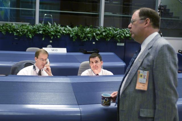
JSC2001-E-25434 (21 August 2001) --- STS-105 flight directors John Shannon (left) and Steve Stich, monitor data at their consoles in the shuttle flight control room (WFCR) in Houston’s Mission Control Center (MCC). Wayne Hale of the Mission Operations Directorate (MOD) is photographed standing in the foreground.
NASA mission controllers, engineers, pilots and communications specialists in the mission control room monitor the supersonic research flight off the coast of Galveston, as part of the QSF18 flight series. The flight operations crew tracks the status of the flights, maintains communications with the aircraft, communicates with U.S. Coast Guard, and coordinates community feedback data.
NASA mission controllers, engineers, pilots and communications specialists in the mission control room monitor the supersonic research flight off the coast of Galveston, as part of the QSF18 flight series. The flight operations crew tracks the status of the flights, maintains communications with the aircraft, communicates with U.S. Coast Guard, and coordinates community feedback data.
NASA mission controllers, engineers, pilots and communications specialists in the mission control room monitor the supersonic research flight off the coast of Galveston, as part of the QSF18 flight series. The flight operations crew tracks the status of the flights, maintains communications with the aircraft, communicates with U.S. Coast Guard, and coordinates community feedback data.
NASA mission controllers, engineers, pilots and communications specialists in the mission control room monitor the supersonic research flight off the coast of Galveston, as part of the QSF18 flight series. The flight operations crew tracks the status of the flights, maintains communications with the aircraft, communicates with U.S. Coast Guard, and coordinates community feedback data.

NASA mission controllers, engineers, pilots and communications specialists in the mission control room monitor the supersonic research flight off the coast of Galveston, as part of the QSF18 flight series. The flight operations crew tracks the status of the flights, maintains communications with the aircraft, communicates with U.S. Coast Guard, and coordinates community feedback data.
jsc2025e057255 --- NASA’s Artemis III lunar science team is pictured in the Science Evaluation Room (SER) at the agency’s Johnson Space Center in Houston. Located in the Christopher C. Kraft Jr. Mission Control Center, the SER supports the mission’s main flight control room for lunar science and planetary observations. Built specifically for Artemis missions with these science priorities in mind, the SER is equipped to support rapid data interpretation, collaborative analysis, real-time decision making, and seamless coordination between the science and operations teams.
S72-35460 (18 April 1972) --- Dr. J.F. Zieglschmid, M.D., Missions Operations Control Room (MOCR) White Team Surgeon, is seated in the Medical Support Room (MSR) in the Mission Control Center (MCC). He monitors crew biomedical data being received from the Apollo 16 spacecraft on the third day of the lunar landing mission.
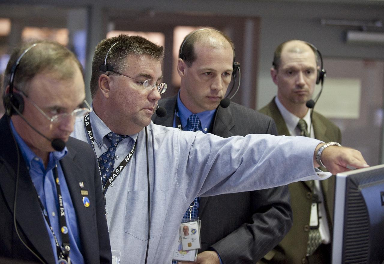
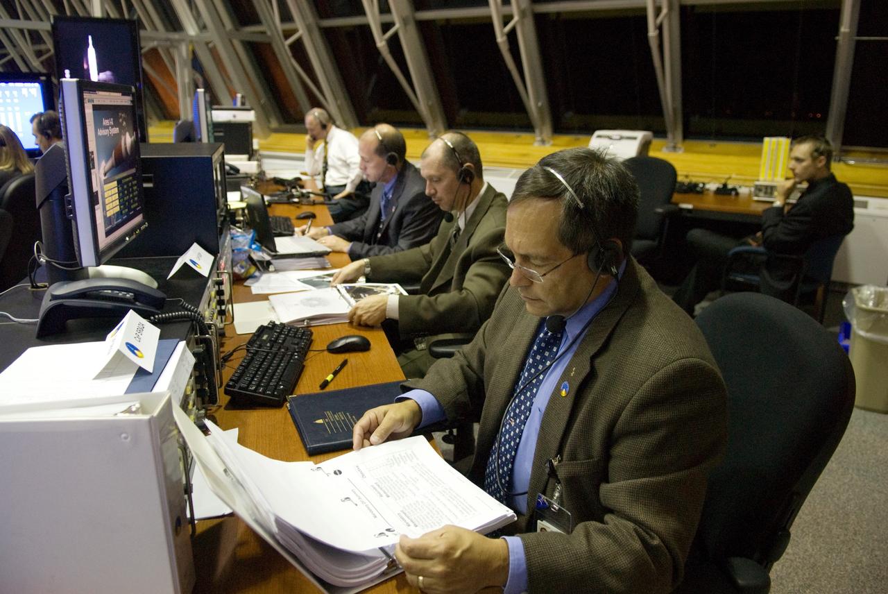
CAPE CANAVERAL, Fla. – In the Mission Director Center in Cape Canaveral Air Force Station's Hangar AE, mission engineers take part in a countdown simulation for the upcoming Ares I-X flight test. Ares I-X is targeted for the test on Oct. 31. The Hangar AE control rooms provide real-time voice, data and video information for ex¬pendable vehicle checkout and launch operations, similar to that provided by the space shuttle control rooms. Photo credit: NASA/Kim Shiflett
jsc2025e057254 --- NASA’s Artemis II lunar science team is pictured in the Science Evaluation Room (SER) at the agency’s Johnson Space Center in Houston. Located in the Christopher C. Kraft Jr. Mission Control Center, the SER supports the mission’s main flight control room for lunar science and planetary observations. Built specifically for Artemis missions with these science priorities in mind, the SER is equipped to support rapid data interpretation, collaborative analysis, real-time decision making, and seamless coordination between the science and operations teams.
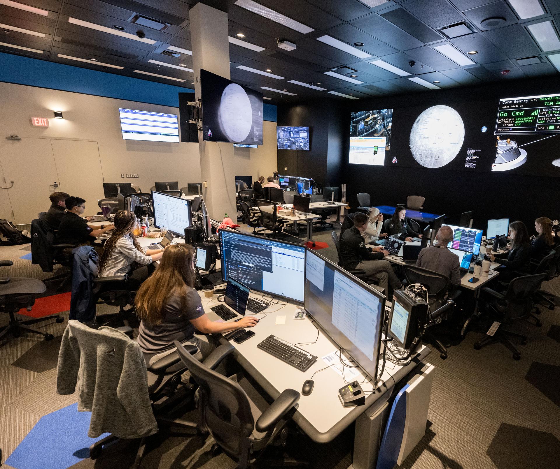
jsc2026e000861 --- The Artemis II Lunar Science Team works in the Science Evaluation Room (SER) during a training simulation in the Mission Control Center at NASA’s Johnson Space Center in Houston. The SER supports the mission’s main flight control room for lunar science and planetary observations. Built specifically for Artemis missions with these science priorities in mind, the SER is equipped to support rapid data interpretation, collaborative analysis, real-time decision making, and seamless coordination between the science and operations teams. Credit: James Blair
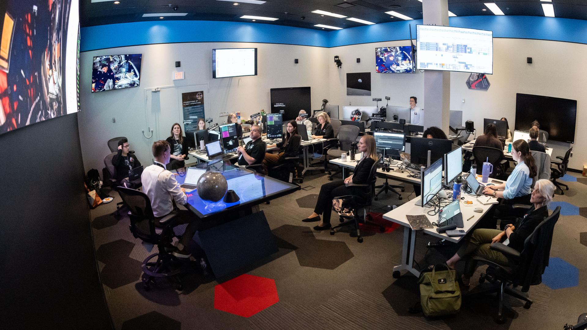
A view inside the Science Evaluation Room (SER) in Mission Control at NASA’s Johnson Space Center in Houston. The SER supports lunar science and planetary observations for the Artemis science officer in the mission’s main flight control room. Built specifically for Artemis missions with these science priorities in mind, the SER is equipped to support rapid data interpretation, collaborative analysis, real-time decision making, and seamless coordination between the science and operations teams. Credits: NASA/Bill Stafford
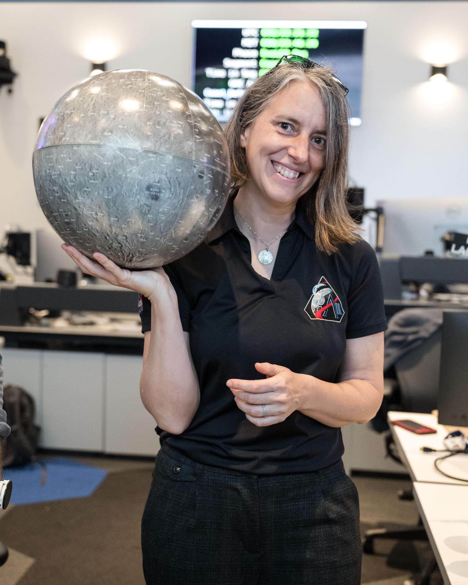
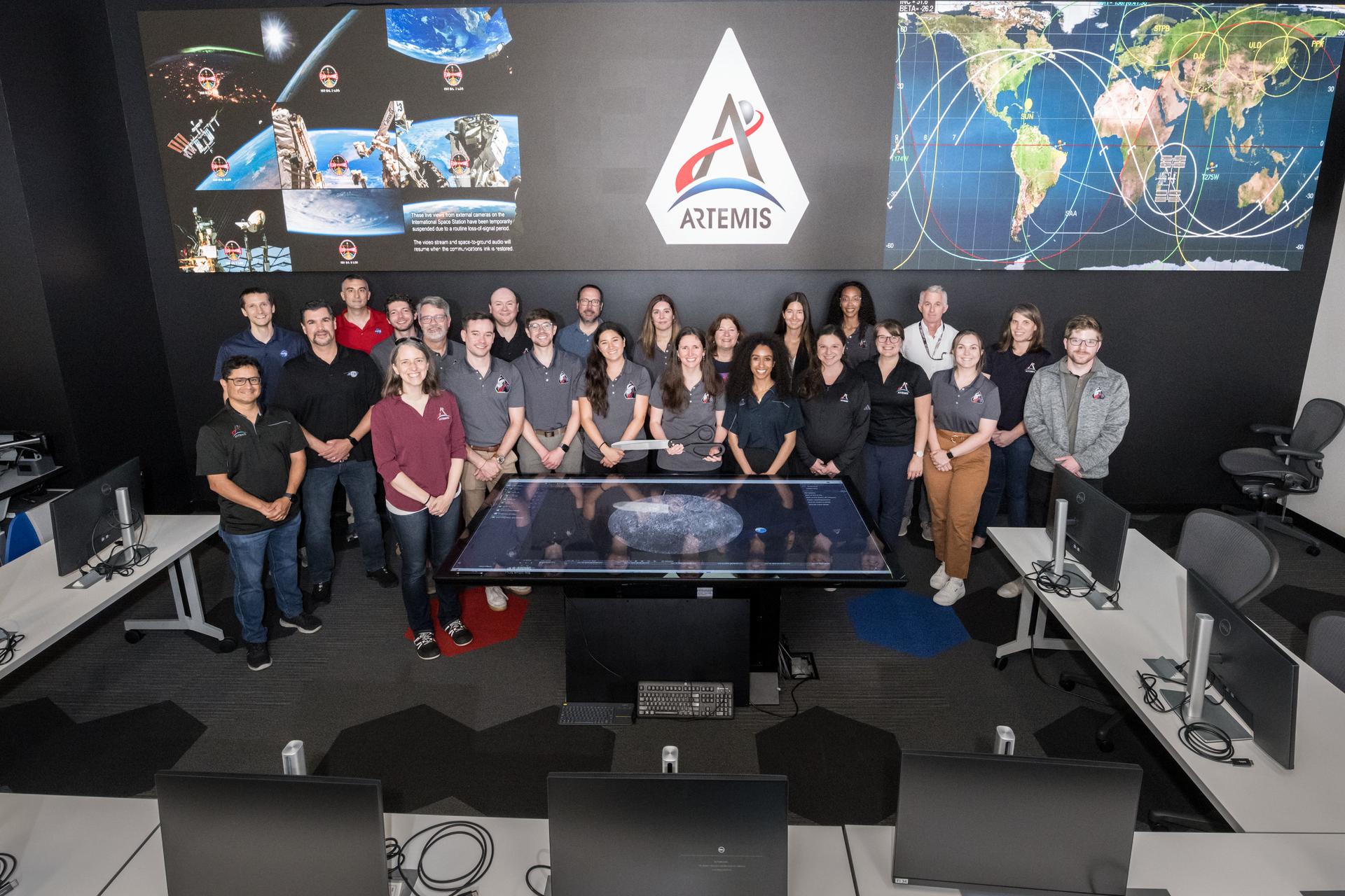
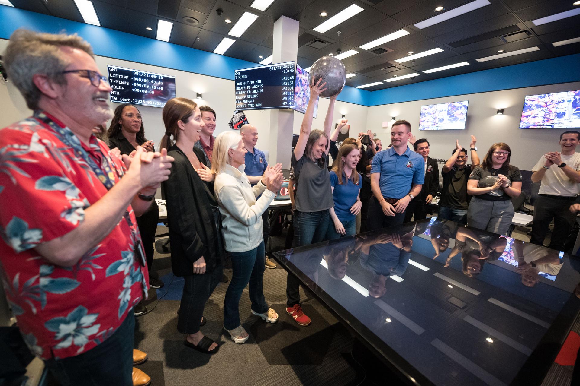
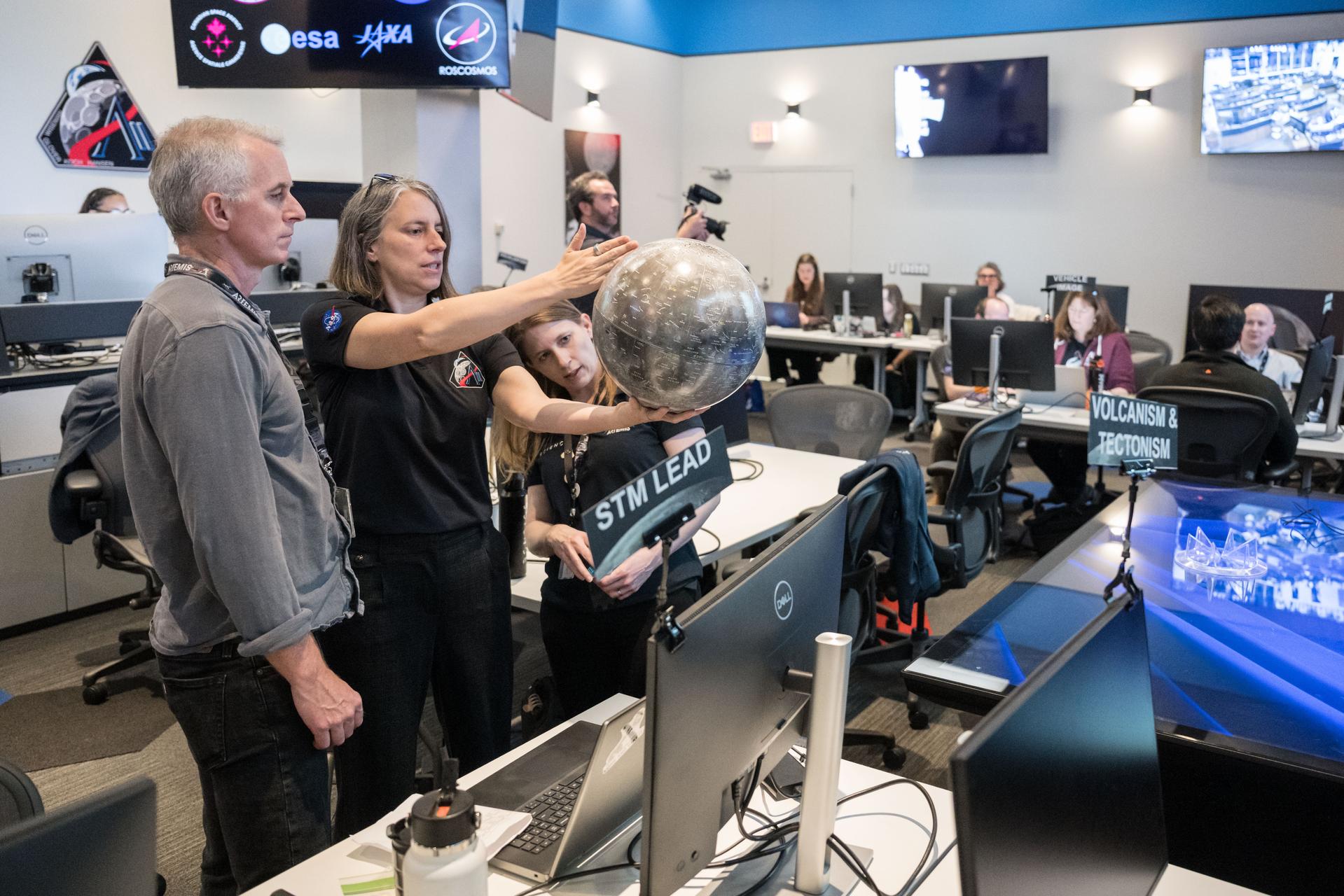
Artemis curation lead, Juliane Gross, holds a lunar globe in the Science Evaluation Room (SER) in Mission Control at Johnson Space Center in Houston. The SER supports lunar science and planetary observations for the Artemis science officer in the mission’s main flight control room. Built specifically for Artemis missions with these science priorities in mind, the SER is equipped to support rapid data interpretation, collaborative analysis, real-time decision making, and seamless coordination between the science and operations teams. Credits: NASA/Luna Posadas Nava
Amelia Kinsella, left, meets NASA astronauts Christina Koch and Victor J. Glover in the Ames Arc Jet control room for the Interaction Heating Facility (IHF), N238, where operators run the Arc Jet and review test data in real time.
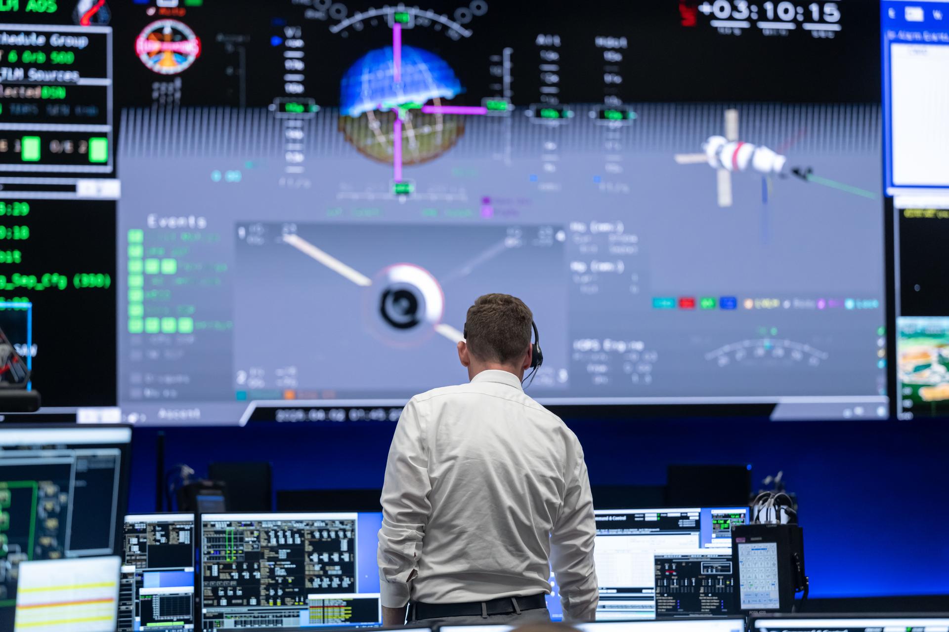
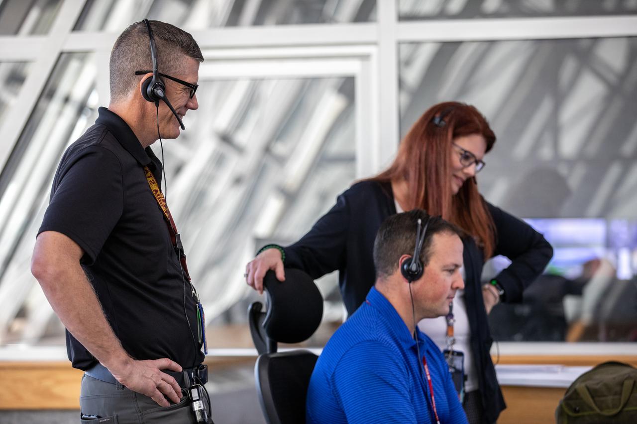
jsc2026e019242 (April 1, 2026) – Lead Artemis II Flight Director Jeff Radigan in the White Flight Control Room at the Mission Control Center at NASA’s Johnson Space Center in Houston. At the time of this photograph, a little over three hours into the mission, the Artemis II crew began a manual piloting test called the proximity operations demonstration. During the demonstration, mission controllers monitored Orion as the astronauts transitioned the spacecraft to manual mode and piloted its flight path and orientation. This demonstration will provide performance data and operational experience that cannot be readily gained on the ground in preparation for critical rendezvous, proximity operations, docking, and undocking for future Artemis missions. Credit: NASA
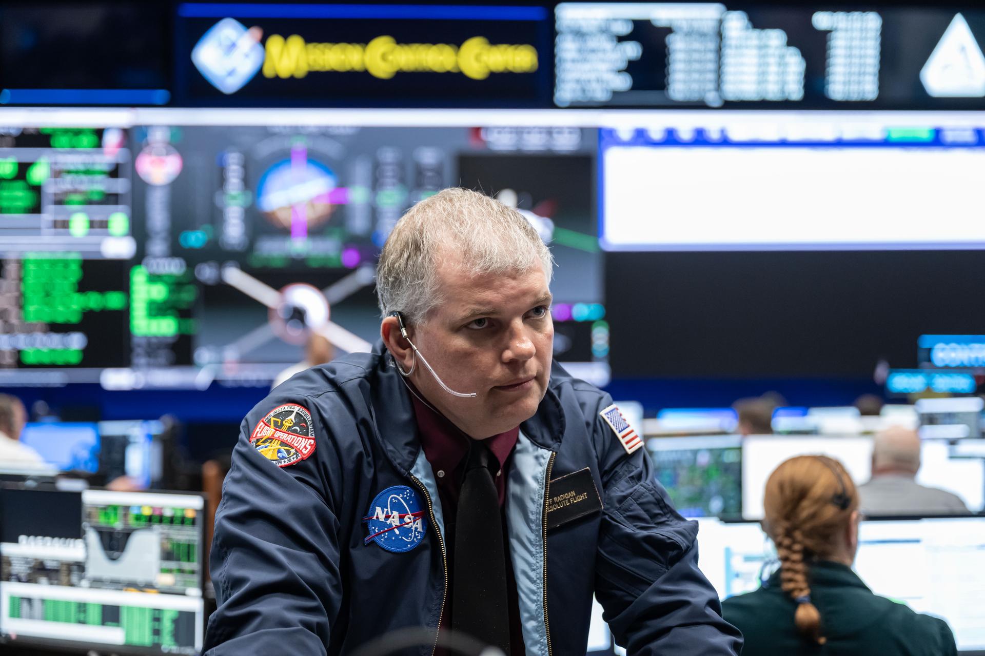
jsc2026e019217 (April 1, 2026) – Lead Artemis II Flight Director Jeff Radigan in the White Flight Control Room at the Mission Control Center at NASA’s Johnson Space Center in Houston. At the time of this photograph, a little over three hours into the mission, the Artemis II crew was conducting a manual piloting test called the proximity operations demonstration. During the demonstration, mission controllers monitored Orion as the astronauts transitioned the spacecraft to manual mode and piloted its flight path and orientation. This demonstration will provide performance data and operational experience that cannot be readily gained on the ground in preparation for critical rendezvous, proximity operations, docking, and undocking for future Artemis missions. Credit: NASA
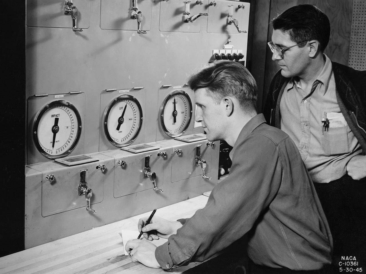
Researchers at the National Advisory Committee for Aeronautics (NACA) Aircraft Engine Research Laboratory monitor a ramjet's performance in the Altitude Wind Tunnel from the control room. The soundproof control room was just a few feet from the tunnel’s 20-foot-diameter test section. In the control room, the operators could control all aspects of the tunnel’s operation, including the air density, temperature, and speed. They also operated the engine or test article in the test section by controlling the angle-of-attack, speed, power, and other parameters. The men in this photograph are monitoring the engine’s thrust and lift. A NACA-designed 20-inch-diameter ramjet was installed in the tunnel in May 1945. Thrust figures from these runs were compared with drag data from tests of scale models in small supersonic tunnels to verify the ramjet’s feasibility. The tunnel was used to analyze the ramjet’s overall performance up to altitudes of 47,000 feet and speeds to Mach 1.84. The researchers found that an increase in altitude caused a reduction in the engine’s horsepower and identified optimal flameholder configurations.
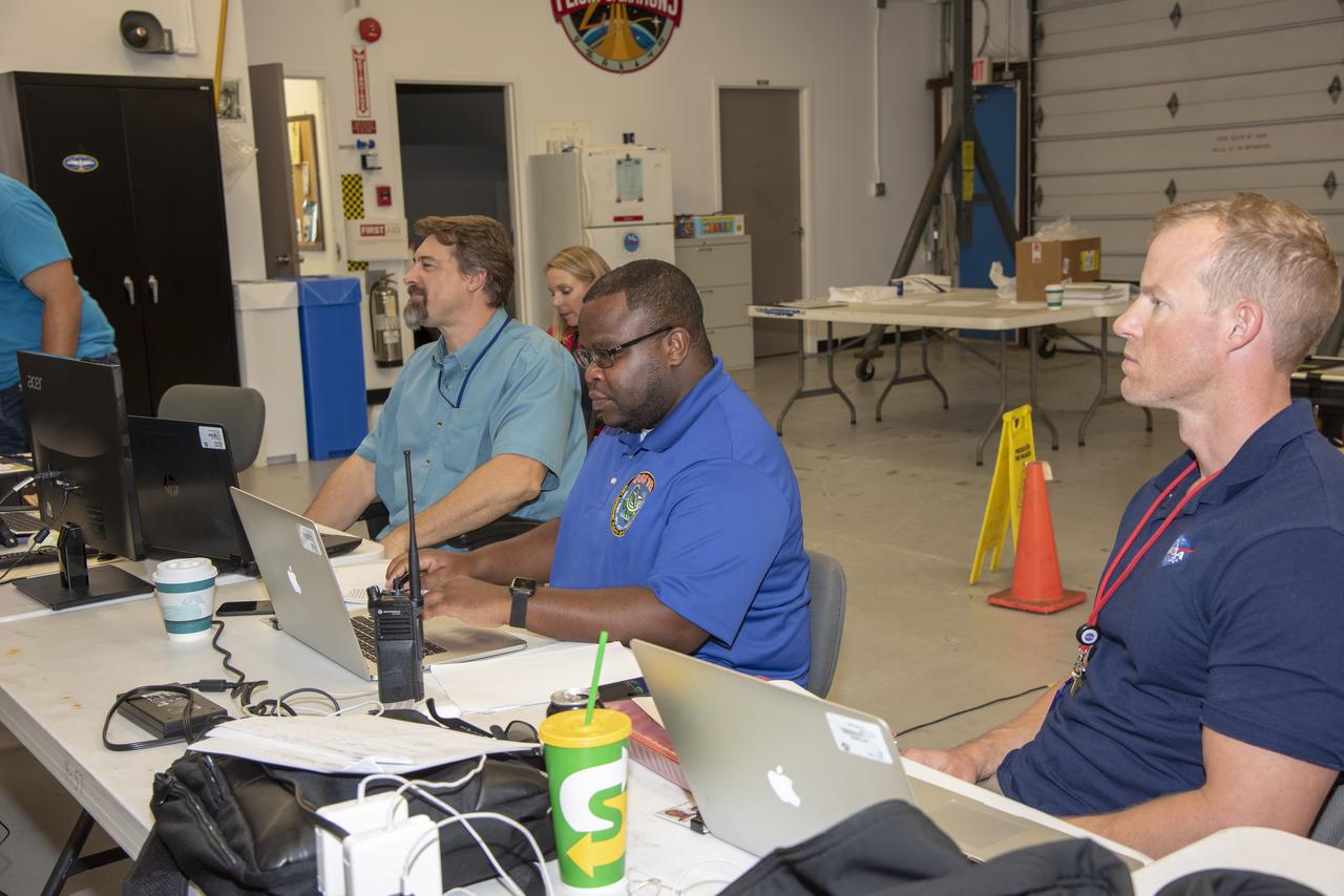
jsc2026e000849 --- The Artemis II Lunar Science Team works in the Science Evaluation Room (SER) during a training simulation at the NASA’s Johnson Space Center in Houston. Located in the Christopher C. Kraft Jr. Mission Control Center, the SER supports the mission’s main flight control room for lunar science and planetary observations. Built specifically for Artemis missions with these science priorities in mind, the SER is equipped to support rapid data interpretation, collaborative analysis, real-time decision making, and seamless coordination between the science and operations teams. Credit: James Blair
Members of the Artemis lunar science team, from left, Sara Schmidt, Megan Borel, Amber Turner, Jacob Richardson, and Juliane Gross pose for a selfie with the Artemis II launch broadcast on the screen behind them in the Science Evaluation Room (SER) in Mission Control at NASA's Johnson Space Center in Houston. The SER supports lunar science and planetary observations for the Artemis science officer in the mission’s main flight control room. Built specifically for Artemis missions with these science priorities in mind, the SER is equipped to support rapid data interpretation, collaborative analysis, real-time decision making, and seamless coordination between the science and operations teams. Credits: NASA/Mark Sowa.
Members of the Artemis lunar science team, from left, Ariel Deutsch, Amber Turner, and Wilfredo Garcia-Lopez, watch the Artemis II launch from the Science Evaluation Room (SER) in Mission Control at Johnson Space Center in Houston. The SER supports lunar science and planetary observations for the Artemis science officer in the mission’s main flight control room. Built specifically for Artemis missions with these science priorities in mind, the SER is equipped to support rapid data interpretation, collaborative analysis, real-time decision making, and seamless coordination between the science and operations teams. Credits: NASA/Mark Sowa.
Members of the Artemis lunar science team cheer as they gather to watch the Artemis II launch broadcast from the Science Evaluation Room (SER) in Mission Control at NASA's Johnson Space Center in Houston. The SER supports lunar science and planetary observations for the Artemis science officer in the mission’s main flight control room. Built specifically for Artemis missions with these science priorities in mind, the SER is equipped to support rapid data interpretation, collaborative analysis, real-time decision making, and seamless coordination between the science and operations teams. Credits: NASA/Mark Sowa.
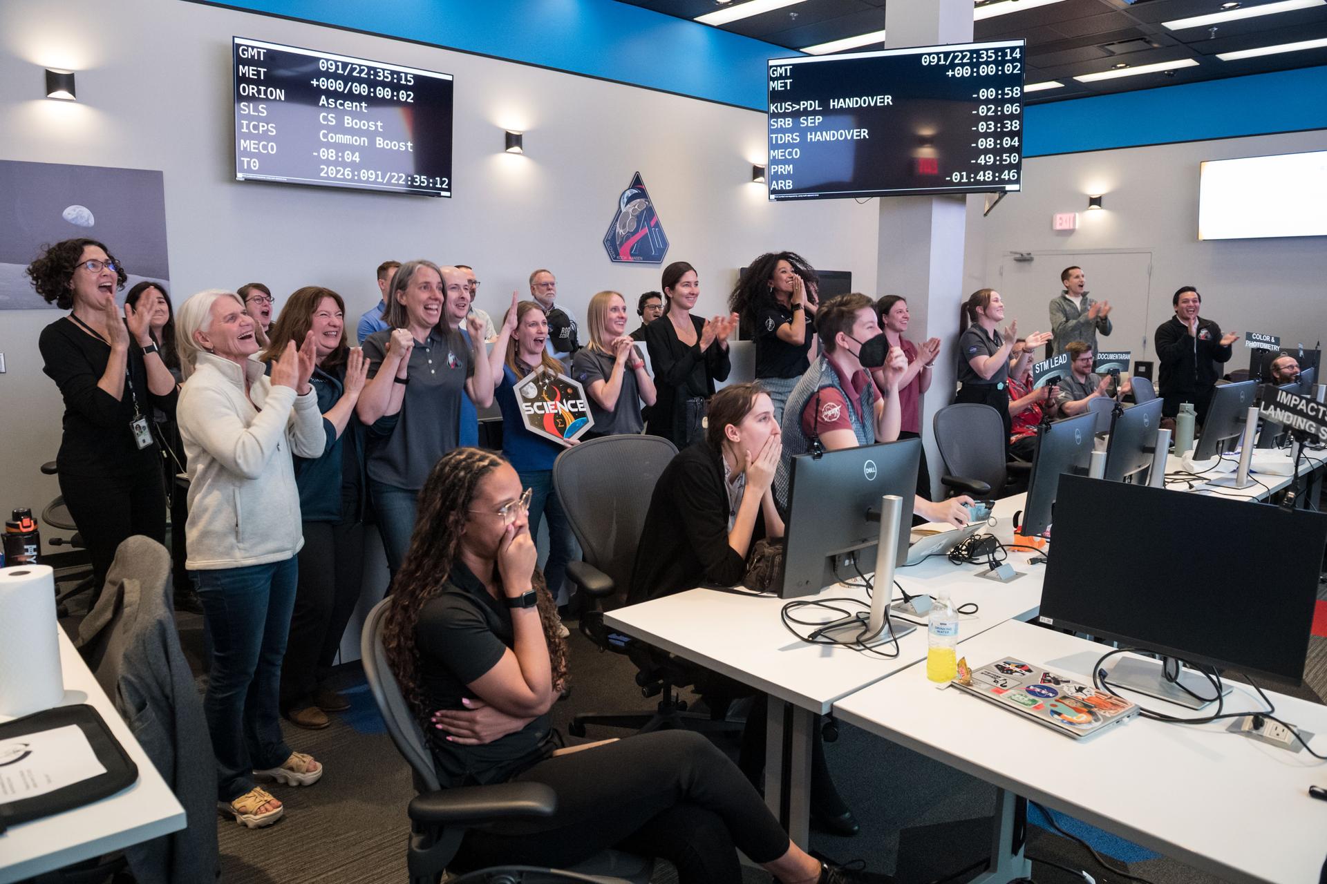
Members of the Artemis lunar science team celebrate the Artemis II launch as they watch from the Science Evaluation Room (SER) in Mission Control at NASA's Johnson Space Center in Houston. The SER supports lunar science and planetary observations for the Artemis science officer in the mission’s main flight control room. Built specifically for Artemis missions with these science priorities in mind, the SER is equipped to support rapid data interpretation, collaborative analysis, real-time decision making, and seamless coordination between the science and operations teams. Credits: NASA/Mark Sowa.
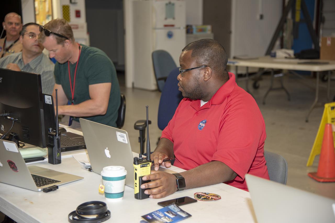
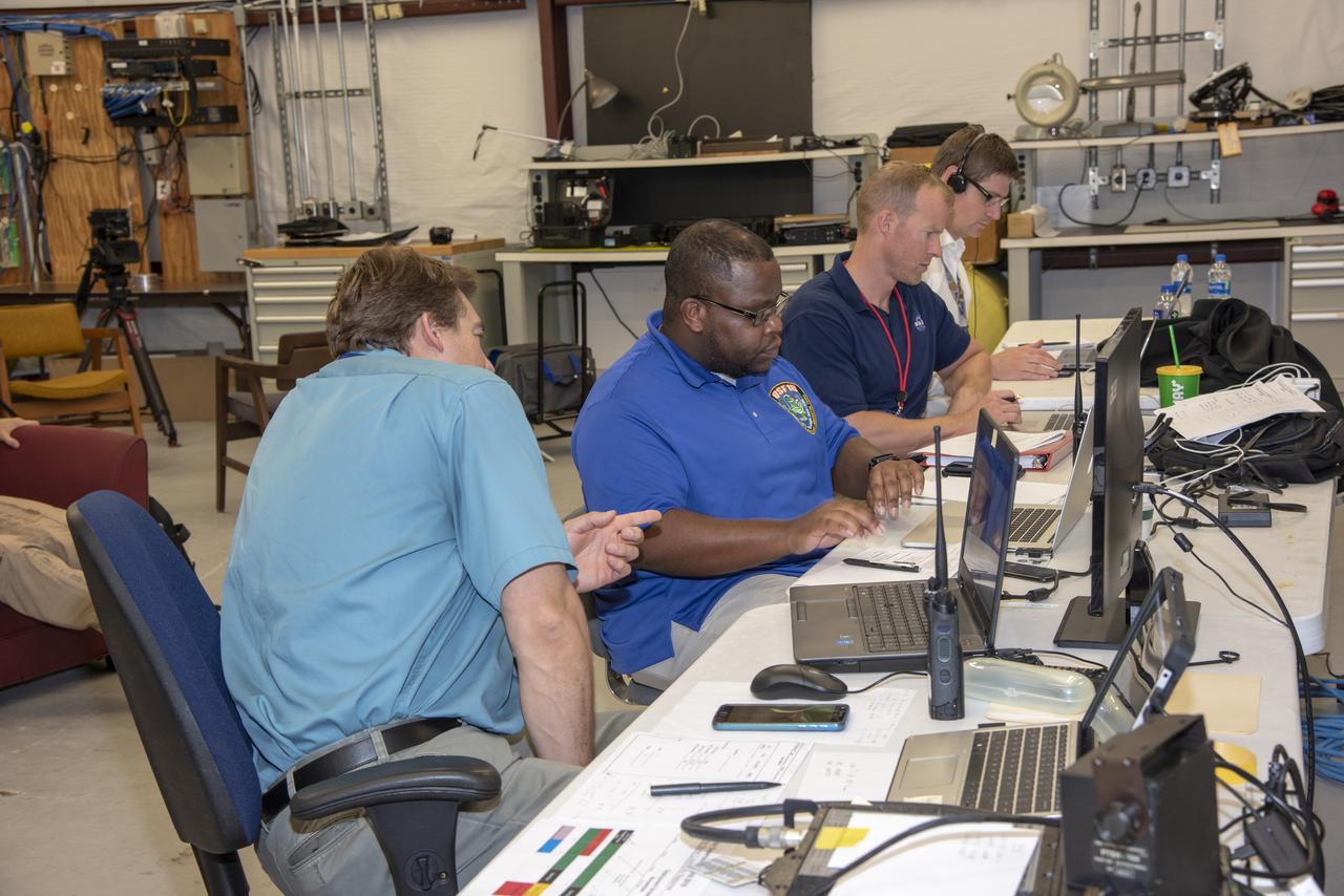
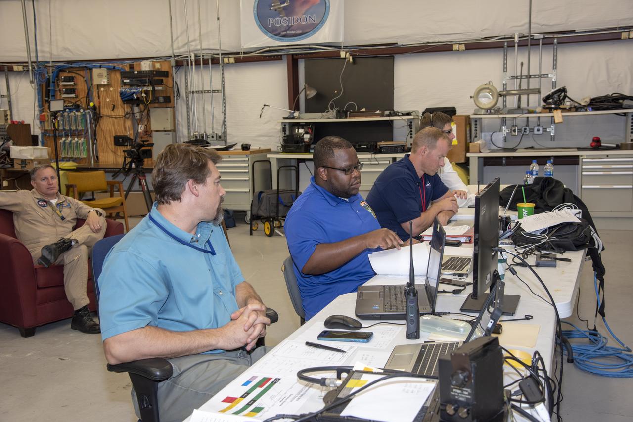
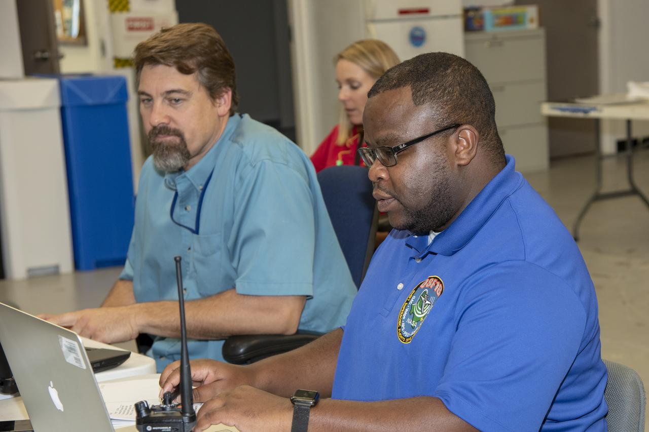
jsc2026e000848 --- Artemis lunar science team members, from left, Jacob Richardson, Marie Henderson, and Kiarre Dumes, monitor a lunar flyby simulation from the Science Evaluation Room (SER) at the NASA’s Johnson Space Center in Houston. Located in the Christopher C. Kraft Jr. Mission Control Center, the SER supports the mission’s main flight control room for lunar science and planetary observations. Built specifically for Artemis missions with these science priorities in mind, the SER is equipped to support rapid data interpretation, collaborative analysis, real-time decision making, and seamless coordination between the science and operations teams. Credit: James Blair
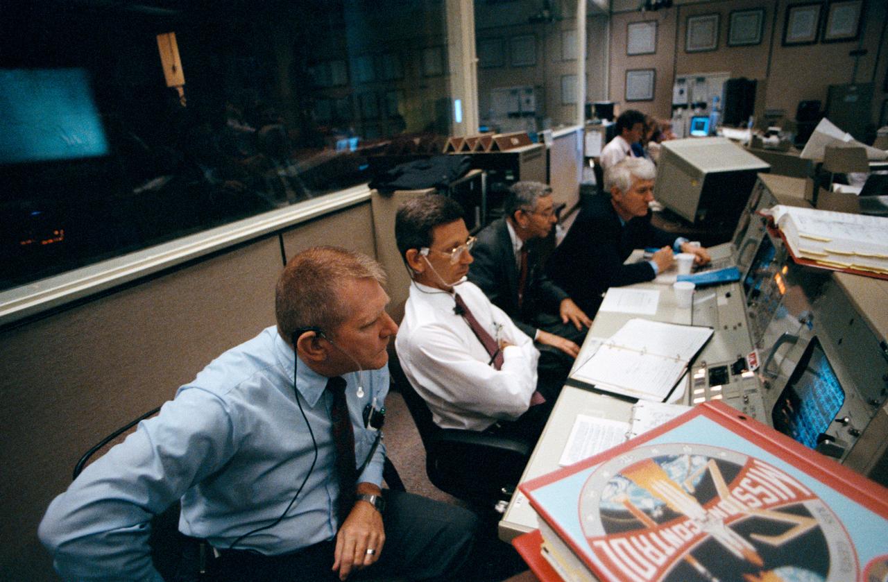
JSC2001-E-21331 (12 July 2001) --- Alan L. (Lee) Briscoe, chief engineer for the Mission Operations Directorate, looks over pre-flight data at the MOD console in the shuttle flight control room (WFCR) in Houston's Mission Control Center (MCC) during the countdown leading up to the launch of the Space Shuttle Atlantis and the beginning of the STS-104 mission.
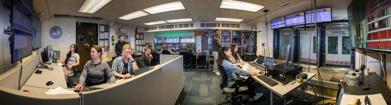
Panorama of the IRT engineering and ice cloud calibration team in the control room. Shown on the left are the data and system engineers. In the center with their backs to the camera are the wind tunnel operators who control the wind speed and super cooled water flow. In the center right of the photo is the video recording system and the test engineers. On the right side the test section can be see though the wind and the TV screen shows the pray bars that create the icing cloud.
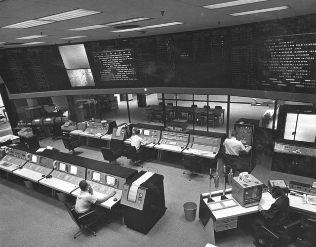
S81-39433 (12 Nov. 1981) --- Flight director Neil B. Hutchinson monitors data displayed on a cathode ray tube (CRT) at his console in the mission operations control room (MOCR) in the Johnson Space Center?s Mission Control Center (MCC) during the launch phase of STS-2. Launch of the Columbia occurred at 9:10 a.m. CST today with astronauts Joe H. Engle and Richard H. Truly aboard the Columbia. Photo credit: NASA
Instrumentation and Communications Officer (INCO) John F. Muratore monitors conventional workstation displays during an STS-26 simulation in JSC Mission Control Center (MCC) Bldg 30 Flight Control Room (FCR). Next to Muratore an operator views the real time data system (RTDS), an expert system. During the STS-29 mission two conventional monochrome console display units will be removed and replaced with RTDS displays. View is for the STS-29 press kit from Office of Aeronautics and Space Technology (OAST) RTDS.
JSC Mission Control Center (MCC) Bldg 30 flight control room (FCR) personnel monitor STS-26 post landing activities and ceremonies at Edwards Air Force Base (EAFB) via their monitors. Displayed on front screens are approach and landing diagrams, data, the space shuttle program insignia, the STS-26 mission insignia, the Mission Operations Directorate insignia, and the STS-26 crew standing in front of Discovery, Orbiter Vehicle (OV) 103.
JSC2002-E-41150 (7 October 2002) --- Flight directors John Shannon (left) and Steve Stich monitor data at their consoles in the shuttle flight control room (WFCR) in Houston’s Mission Control Center (MCC). Wayne Hale (standing) of the Mission Operations Directorate (MOD) looks on. At the time this photo was taken the Space Shuttle Atlantis was about to launch from the Kennedy Space Center, Florida. Atlantis lifted off at 2:46 p.m. (CDT) on October 7, 2002. Once the vehicle cleared the tower in Florida, the Houston-based team of flight controllers took over the ground control of the flight.
Test engineers monitor an engine firing from the control room of the Rocket Engine Test Facility at the National Advisory Committee for Aeronautics (NACA) Lewis Flight Propulsion Laboratory. The Rocket Engine Test Facility, built in the early 1950s, had a rocket stand designed to evaluate high-energy propellants and rocket engine designs. The facility was used to study numerous different types of rocket engines including the Pratt and Whitney RL-10 engine for the Centaur rocket and Rocketdyne’s F-1 and J-2 engines for the Saturn rockets. The Rocket Engine Test Facility was built in a ravine at the far end of the laboratory because of its use of the dangerous propellants such as liquid hydrogen and liquid fluorine. The control room was located in a building 1,600 feet north of the test stand to protect the engineers running the tests. The main control and instrument consoles were centrally located in the control room and surrounded by boards controlling and monitoring the major valves, pumps, motors, and actuators. A camera system at the test stand allowed the operators to view the tests, but the researchers were reliant on data recording equipment, sensors, and other devices to provide test data. The facility’s control room was upgraded several times over the years. Programmable logic controllers replaced the electro-mechanical control devices. The new controllers were programed to operate the valves and actuators controlling the fuel, oxidant, and ignition sequence according to a predetermined time schedule.
Artemis II lunar science team members, from left, Ryan Ewing, Juliane Gross, and Debra Needham, discuss lunar geography ahead of the translunar injection burn that accelerated the Orion spacecraft to break free of Earth’s orbit and began the outbound trajectory toward the Moon. They are in the Science Evaluation Room (SER) a back room that supports lunar science and planetary observations for the Artemis science officer in the mission’s main flight control room. Built specifically for Artemis missions with these science priorities in mind, the SER is equipped to support rapid data interpretation, collaborative analysis, real-time decision making, and seamless coordination between the science and operations teams.
S81-39431 (12 Nov. 1981) --- Eugene F. Kranz, left, and Dr. Christopher C. Kraft Jr. monitor data displayed on the FOD console in the mission operations control room (MOCR) in the Johnson Space Center?s mission control center following the successful launch of the Columbia, and the beginning of NASA?s second space shuttle mission. Dr. Kraft is director of the Johnson Space Center and Kranz is deputy director of the flight operations directorate (FOD) at JSC. Houston time for the launch was approximately 9:10 a.m., Nov 12, 1981. Photo credit: NASA
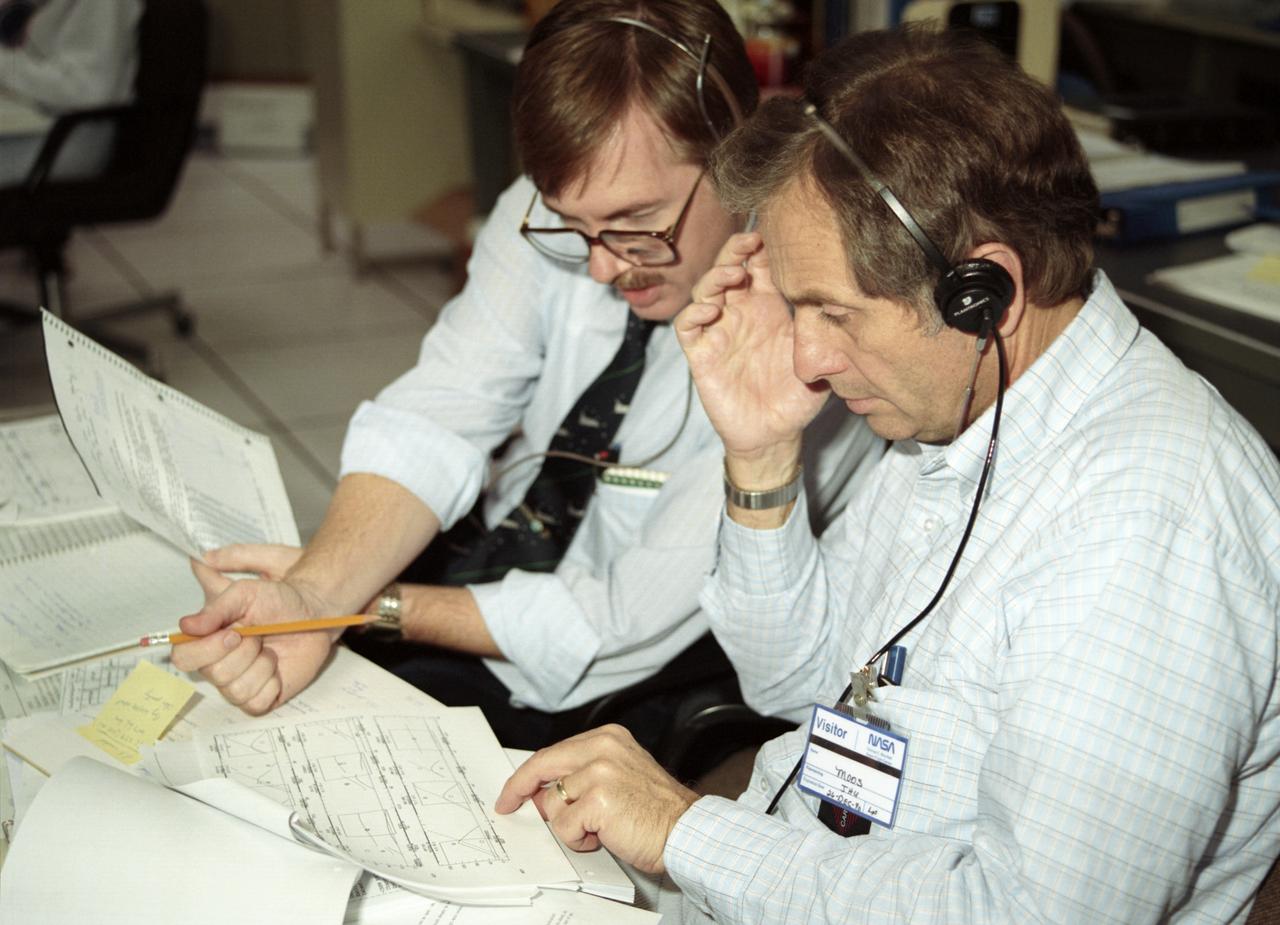
The primary objective of the STS-35 mission was round the clock observation of the celestial sphere in ultraviolet and X-Ray astronomy with the Astro-1 observatory which consisted of four telescopes: the Hopkins Ultraviolet Telescope (HUT); the Wisconsin Ultraviolet Photo-Polarimeter Experiment (WUPPE); the Ultraviolet Imaging Telescope (UIT); and the Broad Band X-Ray Telescope (BBXRT). The Huntsville Operations Support Center (HOSC) Spacelab Payload Operations Control Center (SL POCC) at the Marshall Space Flight Center (MSFC) was the air/ground communication channel used between the astronauts and ground control teams during the Spacelab missions. Teams of controllers and researchers directed on-orbit science operations, sent commands to the spacecraft, received data from experiments aboard the Space Shuttle, adjusted mission schedules to take advantage of unexpected science opportunities or unexpected results, and worked with crew members to resolve problems with their experiments. Due to loss of data used for pointing and operating the ultraviolet telescopes, MSFC ground teams were forced to aim the telescopes with fine tuning by the flight crew. This photo captures the activity of viewing HUT data in the Mission Manager Actions Room during the mission.
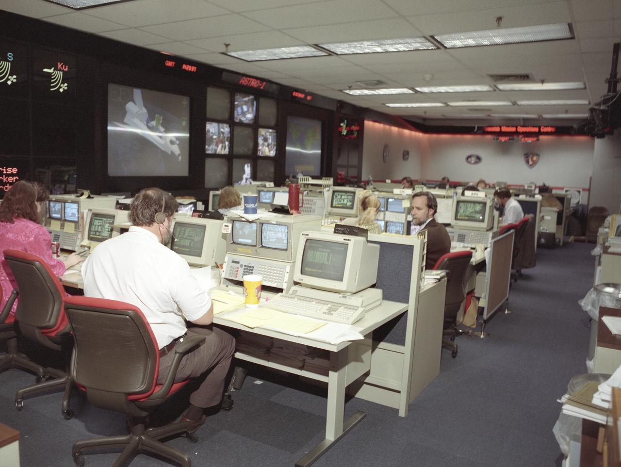
The primary objective of the STS-35 mission was round the clock observation of the celestial sphere in ultraviolet and X-Ray astronomy with the Astro-1 observatory which consisted of four telescopes: the Hopkins Ultraviolet Telescope (HUT); the Wisconsin Ultraviolet Photo-Polarimeter Experiment (WUPPE); the Ultraviolet Imaging Telescope (UIT); and the Broad Band X-Ray Telescope (BBXRT). The Huntsville Operations Support Center (HOSC) Spacelab Payload Operations Control Center (SL POCC) at the Marshall Space Flight Center (MSFC) was the air/ground communication channel used between the astronauts and ground control teams during the Spacelab missions. Teams of controllers and researchers directed on-orbit science operations, sent commands to the spacecraft, received data from experiments aboard the Space Shuttle, adjusted mission schedules to take advantage of unexpected science opportunities or unexpected results, and worked with crew members to resolve problems with their experiments. Due to loss of data used for pointing and operating the ultraviolet telescopes, MSFC ground teams were forced to aim the telescopes with fine tuning by the flight crew. This photo is an overview of the MSFC Payload Control Room (PCR).
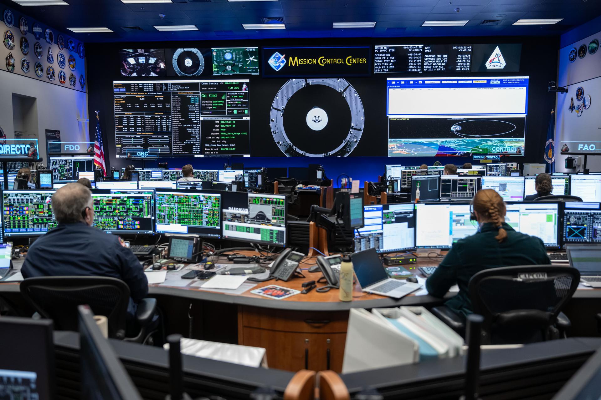
jsc2026e019255 (April 1, 2026) – Lead Artemis II Flight Director Jeff Radigan (left) and capsule communicator (capcom) Amy Dill (right) in the White Flight Control Room at the Mission Control Center at NASA’s Johnson Space Center in Houston. At the time of this photograph, a little over three hours into the mission, the Artemis II crew conducting a manual piloting test called the proximity operations demonstration. During the demonstration, mission controllers monitored Orion as the astronauts transitioned the spacecraft to manual mode and piloted its flight path and orientation. This demonstration will provide performance data and operational experience that cannot be readily gained on the ground in preparation for critical rendezvous, proximity operations, docking, and undocking for future Artemis missions. Credit: NASA
This archival image was released as part of a gallery comparing JPL's past and present, commemorating the 80th anniversary of NASA's Jet Propulsion Laboratory on Oct. 31, 2016. When spacecraft in deep space "phone home," they do it through NASA's Deep Space Network. Engineers in this room at NASA's Jet Propulsion Laboratory -- known as Mission Control -- monitor the flow of data. This image was taken in May 1964, when the building this nerve center is in, the Space Flight Operations Facility (Building 230), was dedicated at JPL. http://photojournal.jpl.nasa.gov/catalog/PIA21120
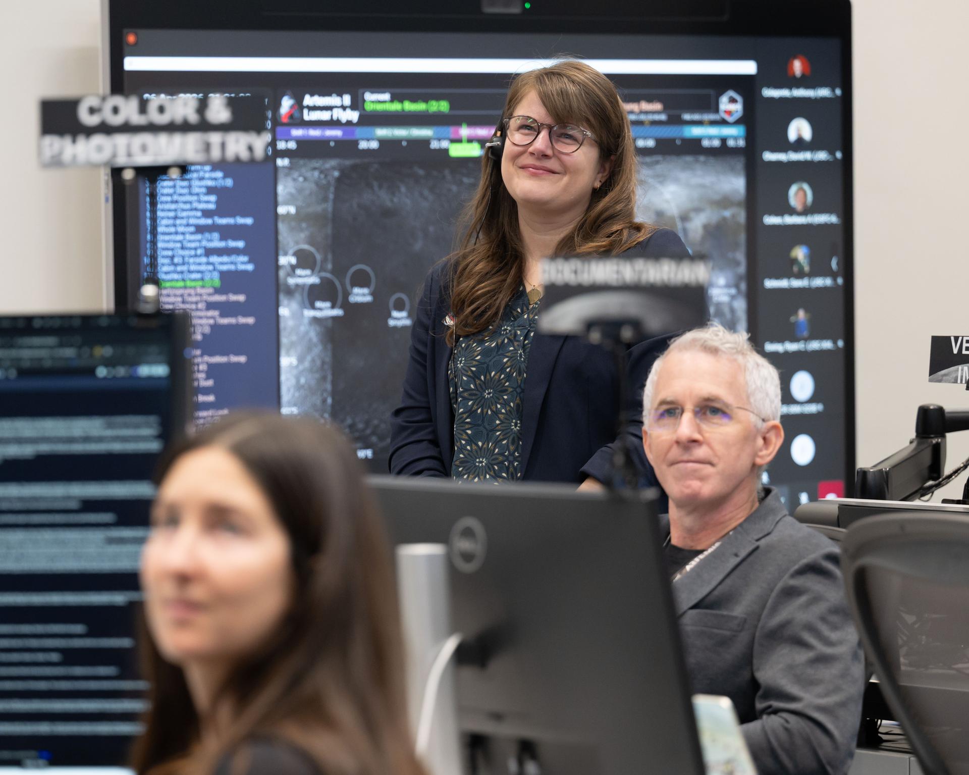
Artemis II lunar science team members, from left, Ryan Ewing, and Barbara Cohen, react to crew observations during the lunar flyby on April 6, 2026. The team worked in the Science Evaluation Room (SER) in Mission Control at NASA’s Johnson Space Center in Houston. Built specifically for Artemis missions with these science priorities in mind, the SER is equipped to support rapid data interpretation, collaborative analysis, real-time decision making, and seamless coordination between the science and operations teams. Credits: NASA/Luna Posadas Nava
The primary objective of the STS-35 mission was round the clock observation of the celestial sphere in ultraviolet and X-Ray astronomy with the Astro-1 observatory which consisted of four telescopes: the Hopkins Ultraviolet Telescope (HUT); the Wisconsin Ultraviolet Photo-Polarimeter Experiment (WUPPE); the Ultraviolet Imaging Telescope (UIT); and the Broad Band X-Ray Telescope (BBXRT). The Huntsville Operations Support Center (HOSC) Spacelab Payload Operations Control Center (SL POCC) at the Marshall Space Flight Center (MSFC) was the air/ground communication channel used between the astronauts and ground control teams during the Spacelab missions. Teams of controllers and researchers directed on-orbit science operations, sent commands to the spacecraft, received data from experiments aboard the Space Shuttle, adjusted mission schedules to take advantage of unexpected science opportunities or unexpected results, and worked with crew members to resolve problems with their experiments. Due to loss of data used for pointing and operating the ultraviolet telescopes, MSFC ground teams were forced to aim the telescopes with fine tuning by the flight crew. This photo captures the activities at the Mission Manager Actions Room during the mission.
STS030-S-004 (8 May 1989) --- JSC Officials monitor early moments of NASA's STS-30 Atlantis, Orbiter Vehicle (OV) 104, flight in the Flight Control Room (FCR) of JSC's Mission Control Center (MCC) Bldg 30. At the Mission Operations Directorate (MOD) console, MOD Director Eugene F. Kranz (foreground), studiously reviews data on a nearby monitor. Others in the photo are (left to right) Flight Directors Office Deputy Chief Lawrence S. Bourgeois, JSC Director Aaron Cohen, and Flight Crew Operations Deputy Director Henry W. Hartsfield, Jr. Kranz'z replete loose-leaf notebook, bearing the insignia of the flight control team members (MOD insignia), is in the foreground.
CAPE CANAVERAL, Fla. – In the Launch Vehicle Data Center- 1 in Cape Canaveral Air Force Station's Hangar AE, (from right) JJ Joyner, Jonathan Cruz and Stuart Cooke take part in a countdown simulation for the upcoming Ares I-X flight test. The LVDC was developed by NASA's Kennedy Space Center to support multiple test operations in parallel or a single large launch operation. The LVDC works in tandem with the adjacent Mission Director Center, the control room where NASA launch managers monitor expendable vehicle launches, and where the final decision to launch is made. Photo credit: NASA/Kim Shiflett
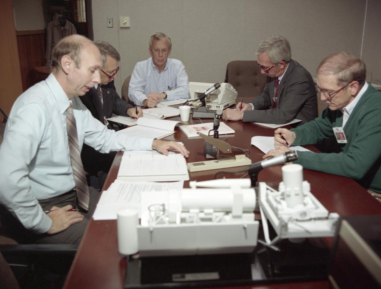
Mission managers, from left, NASA Constellation Program manager Jeff Hanley, Ares I-X Launch Director Ed Mango, Ares I-X mission manager Bob Ess, Ground Operations Manager Philip "Pepper" Phillips, review the latest data in Firing Room One of the Launch Control Center (LCC) at the Kennedy Space Center during the launch countdown of the Ares I-X rocket in Cape Canaveral, Fla., Tuesday, Oct. 27, 2009. The flight test of Ares I-X will provide NASA with an early opportunity to test and prove flight characteristics, hardware, facilities and ground operations associated with the Ares I. Photo Credit: (NASA/Bill Ingalls)
JSC2002-E-08147 (1 March 2002) --- Astronaut Kent V. Rominger (left), Wayne Hale, and Lawrence Bourgeois (background), monitor pre-flight data at the Mission Operation Directorate (MOD) console in the shuttle flight control room (WFCR) in Houston's Mission Control Center (MCC). Several hundred miles away in Florida, the STS-109 crewmembers were awaiting countdown in the crew cabin of the Space Shuttle Columbia on the launch pad at the Kennedy Space Center (KSC). As soon as the vehicle cleared the tower in Florida, the Houston-based team of flight controllers took over the ground control of the mission. Rominger is the Deputy Director of the Flight Crew Operations Directorate (FCOD) and was the FCOD management representative in the MCC. Hale, the Deputy Chief for Space Shuttle of the Flight Director’s Office, served as the MOD management representative. Bourgeois is the Mission Operations Director in the Flight Operations Department at United Space Alliance (USA), and was the USA management representative for STS-109.
Members of the Artemis I launch team monitor data at their consoles inside Firing Room 1 of the Rocco A. Petrone Launch Control Center at NASA’s Kennedy Space Center in Florida during a cryogenic propellant tanking demonstration on Sept. 21, 2022. The first in a series of increasingly complex missions, Artemis I will provide a foundation for human deep space exploration and demonstrate our commitment and capability to extend human presence to the Moon and beyond. The primary goal of Artemis I is to thoroughly test the integrated systems before crewed missions by operating the spacecraft in a deep space environment, testing Orion’s heat shield, and recovering the crew module after reentry, descent, and splashdown.
Members of the Artemis I launch team monitor data at their consoles inside Firing Room 1 of the Rocco A. Petrone Launch Control Center at NASA’s Kennedy Space Center in Florida during a cryogenic propellant tanking demonstration on Sept. 21, 2022. The first in a series of increasingly complex missions, Artemis I will provide a foundation for human deep space exploration and demonstrate our commitment and capability to extend human presence to the Moon and beyond. The primary goal of Artemis I is to thoroughly test the integrated systems before crewed missions by operating the spacecraft in a deep space environment, testing Orion’s heat shield, and recovering the crew module after reentry, descent, and splashdown.
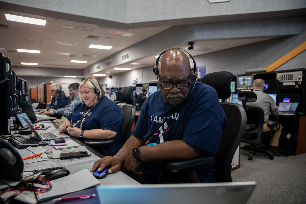
Members of the Artemis I launch team monitor data at their consoles inside Firing Room 1 of the Rocco A. Petrone Launch Control Center at NASA’s Kennedy Space Center in Florida during a cryogenic propellant tanking demonstration on Sept. 21, 2022. The first in a series of increasingly complex missions, Artemis I will provide a foundation for human deep space exploration and demonstrate our commitment and capability to extend human presence to the Moon and beyond. The primary goal of Artemis I is to thoroughly test the integrated systems before crewed missions by operating the spacecraft in a deep space environment, testing Orion’s heat shield, and recovering the crew module after reentry, descent, and splashdown.
Test conductor, Lucas Tucker, monitors thermal vacuum testing operations in the Ocean Color Instrument (OCI) control room during the environmental test campaign. OCI is a highly advanced optical spectrometer that will be used to measure properties of light over portions of the electromagnetic spectrum. It will enable continuous measurement of light at finer wavelength resolution than previous NASA satellite sensors, extending key system ocean color data records for climate studies. OCI is PACE's (Plankton, Aerosol, Cloud, ocean Ecosystem) primary sensor built at Goddard Space Flight Center in Greenbelt, MD.
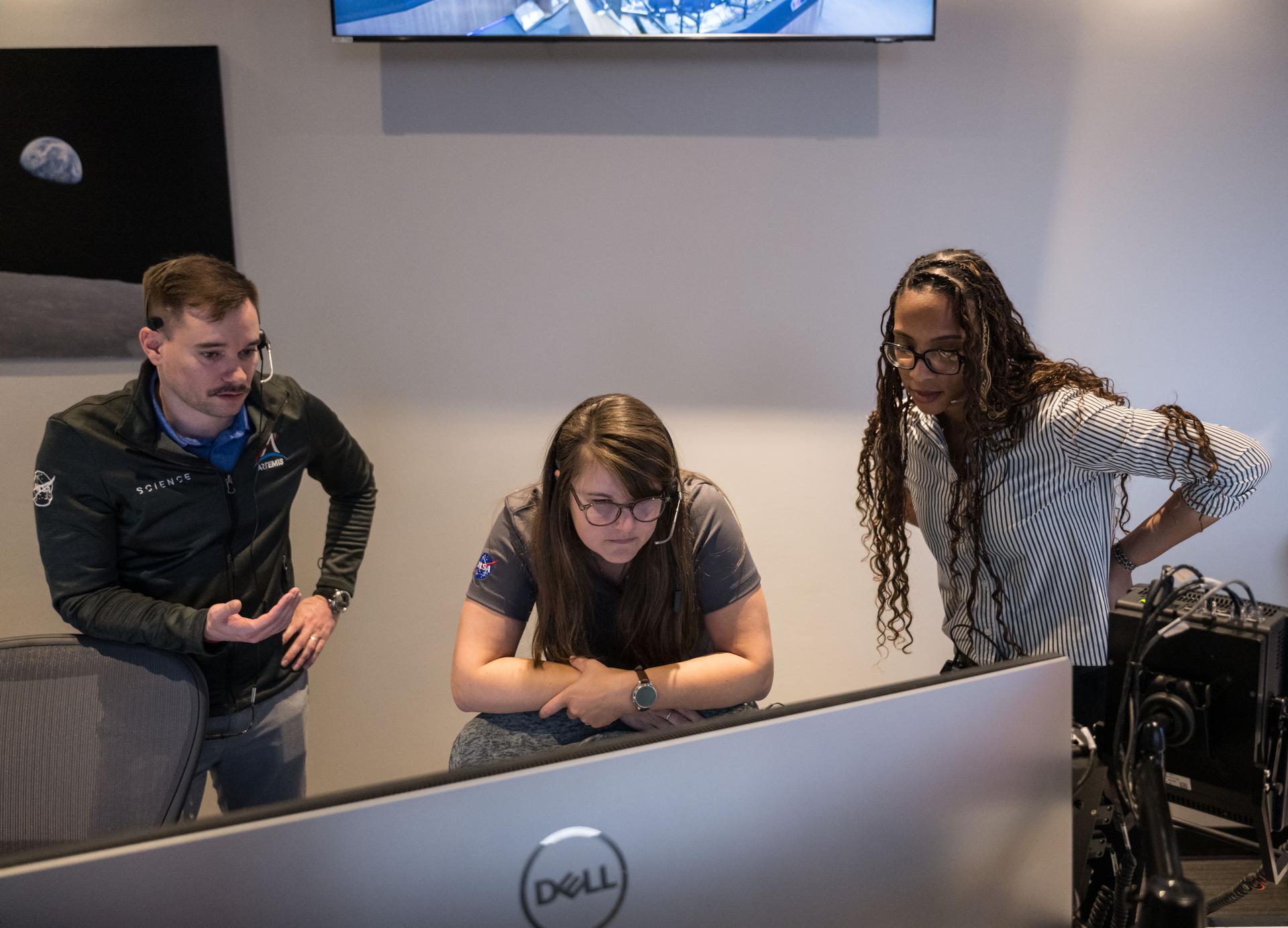
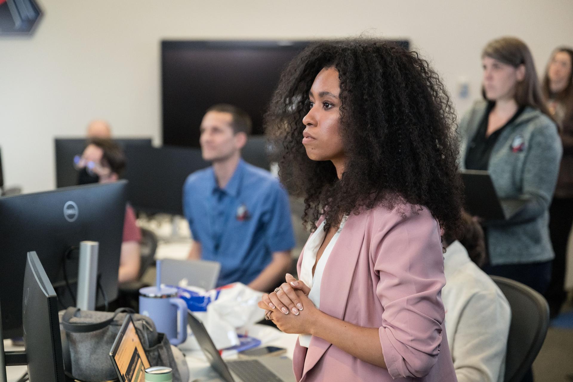
Artemis II lunar science team members, from left, Alexadra Constantinou, David Hollibaugh-Baker, participate in the team’s final preparations for the lunar flyby. NASA Johnson public affairs officer, Victoria Segovia, is seen in the background. The team worked in the Science Evaluation Room (SER) in Mission Control at NASA’s Johnson Space Center in Houston. Built specifically for Artemis missions with these science priorities in mind, the SER is equipped to support rapid data interpretation, collaborative analysis, real-time decision making, and seamless coordination between the science and operations teams. Credits: Credits: NASA/ Robert Markowitz
Artemis II lunar science team members, from left, Cindy Evans, and Wilfredo Garcia Lopez, react to crew observations during the lunar flyby on April 6, 2026. The team worked in the Science Evaluation Room (SER) in Mission Control at NASA’s Johnson Space Center in Houston. Built specifically for Artemis missions with these science priorities in mind, the SER is equipped to support rapid data interpretation, collaborative analysis, real-time decision making, and seamless coordination between the science and operations teams. Credits: NASA/Luna Posadas Nava
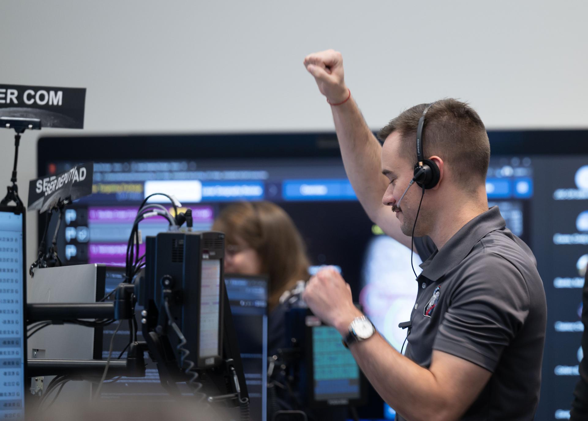
Artemis II deputy lunar science lead, Jacob Richardson, celebrates with a dance after hearing astronauts describe seeing impact flashes on the Moon during their lunar flyby on April 6, 2026. Richardson was monitoring the flyby from the Science Evaluation Room (SER) in Mission Control at NASA’s Johnson Space Center in Houston. Built specifically for Artemis missions with these science priorities in mind, the SER is equipped to support rapid data interpretation, collaborative analysis, real-time decision making, and seamless coordination between the science and operations teams. Credits: NASA/Luna Posadas Nava
Artemis II deputy lunar science lead Marie Henderson, background, and lunar science team members, Ariel Deutsch, and Ryan Ewing, react to crew observations during the lunar flyby on April 6, 2026. The team worked in the Science Evaluation Room (SER) in Mission Control at NASA’s Johnson Space Center in Houston. Built specifically for Artemis missions with these science priorities in mind, the SER is equipped to support rapid data interpretation, collaborative analysis, real-time decision making, and seamless coordination between the science and operations teams. Credits: NASA/Luna Posadas Nava
Artemis II lunar science team member, foreground, Amber Turner, and David Hollibaugh-Baker, and Cherie Achilles, background, participate in the team’s analysis of crew observations during the lunar flyby on April 6, 2026. The team worked in the Science Evaluation Room (SER) in Mission Control at NASA’s Johnson Space Center in Houston. Built specifically for Artemis missions with these science priorities in mind, the SER is equipped to support rapid data interpretation, collaborative analysis, real-time decision making, and seamless coordination between the science and operations teams. Credits: NASA/ Robert Markowitz
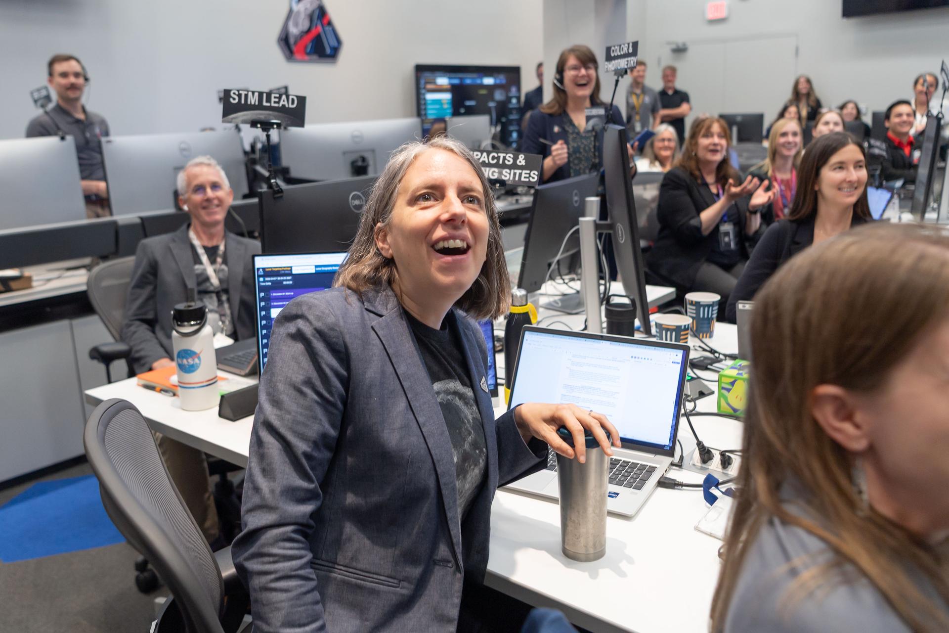
Artemis II lunar science team member, Juliane Gross, center, and the extended lunar science team behind her, celebrates crew observations made during the lunar flyby on April 6. The team worked in the Science Evaluation Room (SER) in Mission Control at NASA’s Johnson Space Center in Houston. Built specifically for Artemis missions with these science priorities in mind, the SER is equipped to support rapid data interpretation, collaborative analysis, real-time decision making, and seamless coordination between the science and operations teams. Credits: NASA/Luna Posadas Nava
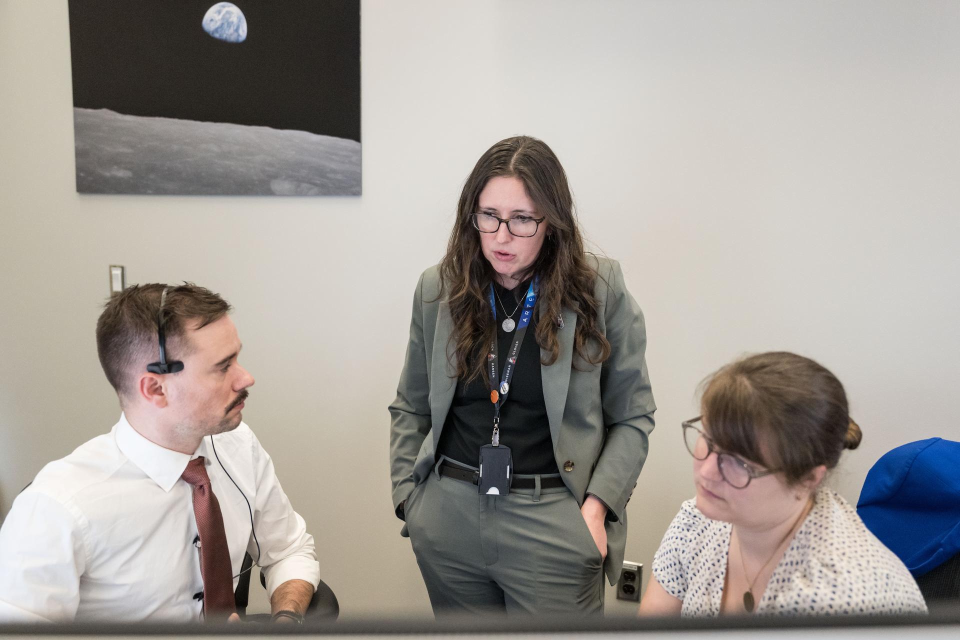
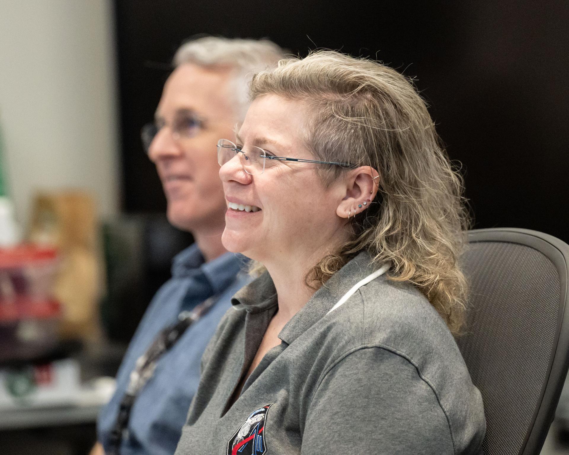
From left, Artemis II deputy lunar science lead, Jacob Richardson, science officer and lunar science lead, Kelsey Young, and deputy lunar science lead, Marie Henderson, discuss the team’s final preparations for the lunar flyby. The team worked in the Science Evaluation Room (SER) in Mission Control at NASA’s Johnson Space Center in Houston. Built specifically for Artemis missions with these science priorities in mind, the SER is equipped to support rapid data interpretation, collaborative analysis, real-time decision making, and seamless coordination between the science and operations teams. Credits: NASA/ Robert Markowitz
Artemis II lunar science team members, in the foreground from left: Amber Turner and Jared Ralleta in the center. Standing up behind Turner is Jacob Richardson, and sitting behind and to the right, of Ralleta, are Ryan Watkins in the front, and Debra Needham behind her. The SER supports the Artemis science officer in the mission’s main flight control room. Built specifically for Artemis missions with these science priorities in mind, the SER is equipped to support rapid data interpretation, collaborative analysis, real-time decision making, and seamless coordination between the science and operations teams. Credits: NASA/Luna Posadas Nava
The test data recording equipment located in the office building of the 10-by 10-Foot Supersonic Wind Tunnel at the NASA Lewis Research Center. The data system was the state of the art when the facility began operating in 1955 and was upgraded over time. NASA engineers used solenoid valves to measure pressures from different locations within the test section. Up 48 measurements could be fed into a single transducer. The 10-by 10 data recorders could handle up to 200 data channels at once. The Central Automatic Digital Data Encoder (CADDE) converted this direct current raw data from the test section into digital format on magnetic tape. The digital information was sent to the Lewis Central Computer Facility for additional processing. It could also be displayed in the control room via strip charts or oscillographs. The 16-by 56-foot long ERA 1103 UNIVAC mainframe computer processed most of the digital data. The paper tape with the raw data was fed into the ERA 1103 which performed the needed calculations. The information was then sent back to the control room. There was a lag of several minutes before the computed information was available, but it was exponentially faster than the hand calculations performed by the female computers. The 10- by 10-foot tunnel, which had its official opening in May 1956, was built under the Congressional Unitary Plan Act which coordinated wind tunnel construction at the NACA, Air Force, industry, and universities. The 10- by 10 was the largest of the three NACA tunnels built under the act.
CAPE CANAVERAL, Fla. - The launch authority team for the Ares I-X flight test monitors the countdown from consoles in the Operations Management Room of the Young-Crippen Firing Room, a glass partitioned area overlooking the main floor, in the Launch Control Center at NASA's Kennedy Space Center in Florida. This will be the first launch from Kennedy's pads of a vehicle other than the space shuttle since the Apollo Program's Saturn rockets were retired. The parts used to make the Ares I-X booster flew on 30 different shuttle missions ranging from STS-29 in 1989 to STS-106 in 2000. The data returned from more than 700 sensors throughout the rocket will be used to refine the design of future launch vehicles and bring NASA one step closer to reaching its exploration goals. For information on the Ares I-X vehicle and flight test, visit http://www.nasa.gov/aresIX. Photo credit: NASA/Kim Shiflett
CAPE CANAVERAL, Fla. - The launch authority team for the Ares I-X flight test monitors the countdown from consoles in the Operations Management Room of the Young-Crippen Firing Room, a glass partitioned area overlooking the main floor, in the Launch Control Center at NASA's Kennedy Space Center in Florida. This will be the first launch from Kennedy's pads of a vehicle other than the space shuttle since the Apollo Program's Saturn rockets were retired. The parts used to make the Ares I-X booster flew on 30 different shuttle missions ranging from STS-29 in 1989 to STS-106 in 2000. The data returned from more than 700 sensors throughout the rocket will be used to refine the design of future launch vehicles and bring NASA one step closer to reaching its exploration goals. For information on the Ares I-X vehicle and flight test, visit http://www.nasa.gov/aresIX. Photo credit: NASA/Kim Shiflett
JSC2004-E-19651 (20 April 2004) --- Astronauts Edward T. Lu (left) and Gregory E. Chamitoff, discuss data at the spacecraft communicator (CAPCOM) console in the shuttle flight control room (WFCR) in Houston?s Mission Control Center (MCC) during rendezvous and docking operations between the Soyuz TMA-4 spacecraft and the International Space Station (ISS). The Soyuz, which carried cosmonaut Gennady I. Padalka, Russia?s Federal Space Agency Expedition 9 commander; astronaut Edward M. (Mike) Fincke, NASA ISS science officer and flight engineer; and European Space Agency (ESA) astronaut Andre Kuipers of the Netherlands, docked with the Station at 12:01 a.m. (CDT) on April 21, 2004.
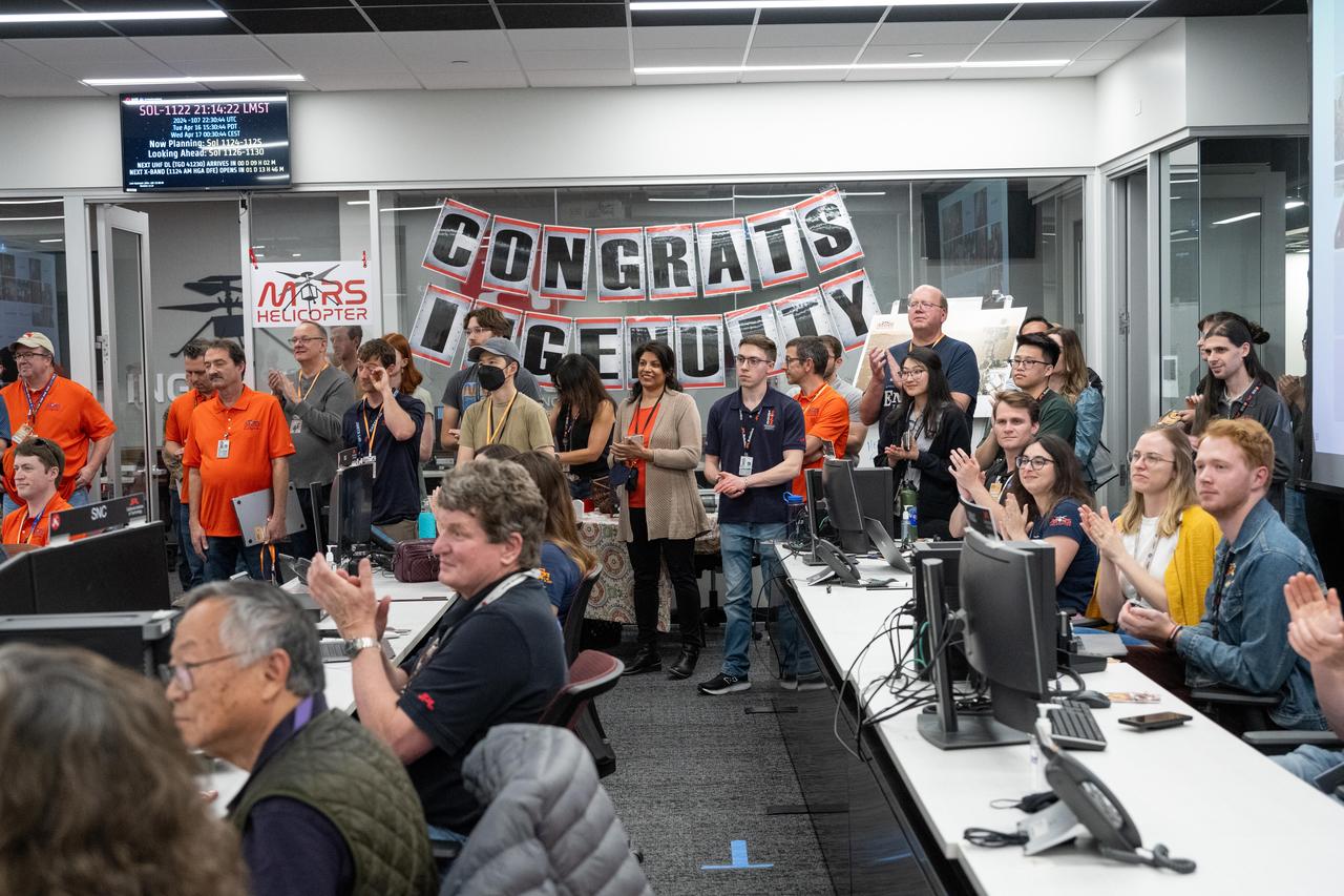
Engineers working on NASA's Ingenuity Mars Helicopter gathered together in a control room for one last time to monitor a transmission from the history-making helicopter at the agency's Jet Propulsion Laboratory on April 16, 2024. The transmission confirmed the operation of a software patch that will allow Ingenuity to act as a stationary testbed and collect data that could benefit future explorers of the Red Planet. Originally designed as short-lived technology demonstration mission that would perform up to five experimental test flights over 30 days, the first aircraft on another world operated from the Martian surface for almost three years, flew more than 14 times farther than planned, and logged more than two hours of total flight time. Its 72nd and final flight was Jan. 18, 2024. https://photojournal.jpl.nasa.gov/catalog/PIA26318
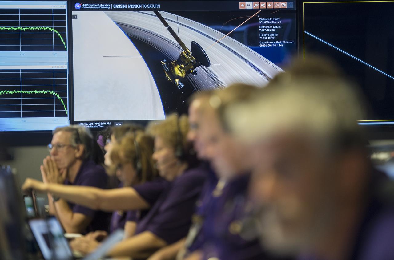
A monitor in the mission control room shows a visualization of Cassini as it makes its final plunge into Saturn, Friday, Sept. 15, 2017 at NASA's Jet Propulsion Laboratory in Pasadena, California. Since its arrival in 2004, the Cassini-Huygens mission has been a discovery machine, revolutionizing our knowledge of the Saturn system and captivating us with data and images never before obtained with such detail and clarity. On Sept. 15, 2017, operators deliberately plunged the spacecraft into Saturn, as Cassini gathered science until the end. Loss of contact with the Cassini spacecraft occurred at 7:55 a.m. EDT (4:55 a.m. PDT). The “plunge” ensures Saturn’s moons will remain pristine for future exploration. During Cassini’s final days, mission team members from all around the world gathered at NASA’s Jet Propulsion Laboratory, Pasadena, California, to celebrate the achievements of this historic mission. Photo Credit: (NASA/Joel Kowsky)
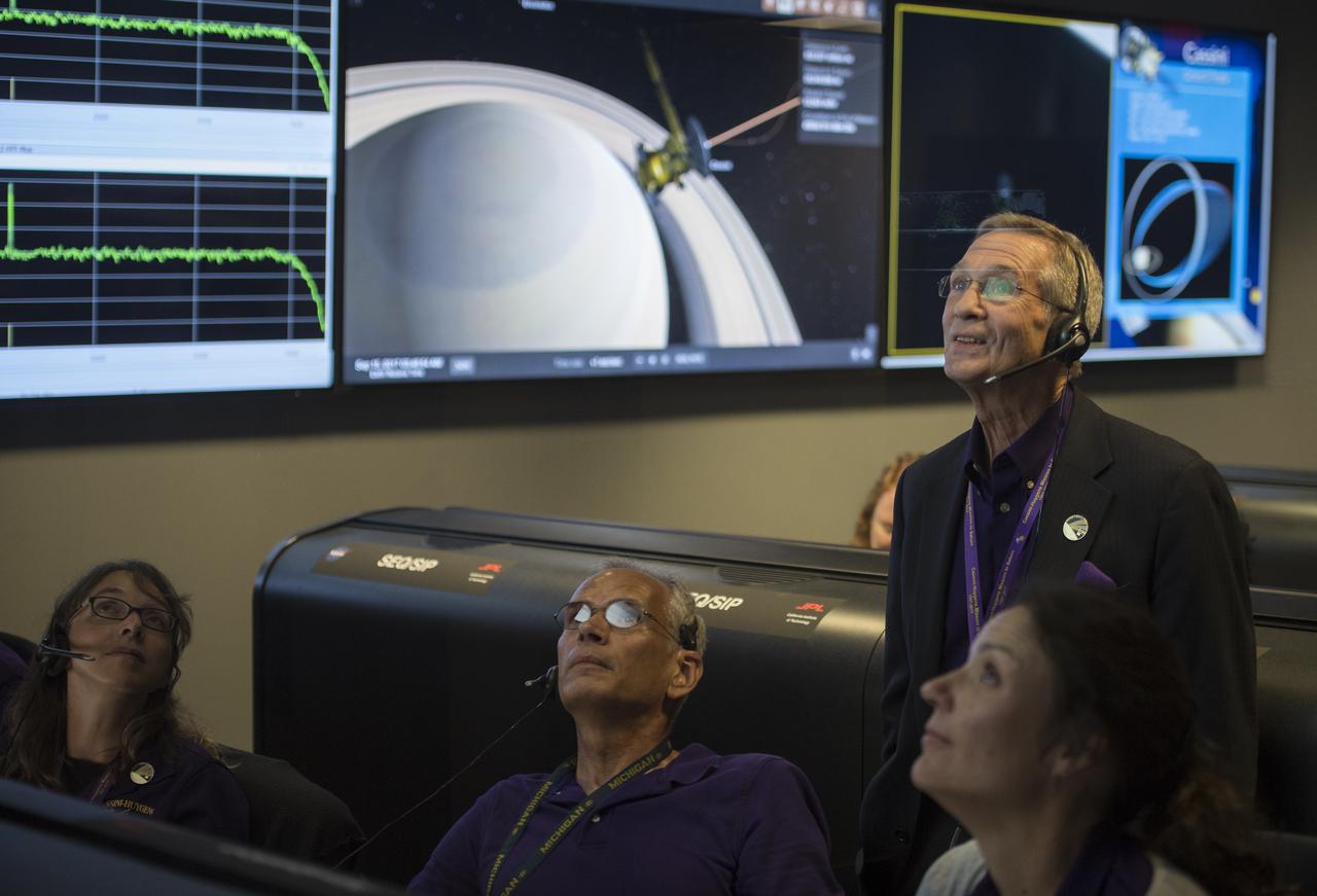
Cassini program manager at JPL, Earl Maize, standing, watches telemetry come in from Cassini with Julie Bellerose, left, Duane Roth, second from left, and Mar Vaquero of the Cassini navigation team in the mission control room, Friday, Sept. 15, 2017 at NASA's Jet Propulsion Laboratory in Pasadena, California. Since its arrival in 2004, the Cassini-Huygens mission has been a discovery machine, revolutionizing our knowledge of the Saturn system and captivating us with data and images never before obtained with such detail and clarity. On Sept. 15, 2017, operators deliberately plunged the spacecraft into Saturn, as Cassini gathered science until the end. The “plunge” ensures Saturn’s moons will remain pristine for future exploration. During Cassini’s final days, mission team members from all around the world gathered at NASA’s Jet Propulsion Laboratory, Pasadena, California, to celebrate the achievements of this historic mission. Photo Credit: (NASA/Joel Kowsky)
CAPE CANAVERAL, Fla. – At the Astrotech Space Operations facility in Titusville, Fla., workers in the control room monitor the data on computer screens from the movement of the high-gain antenna on the Solar Dynamics Observatory, or SDO. The SDO is undergoing performance testing. All of the spacecraft science instruments are being tested in their last major evaluation before launch. SDO is the first space weather research network mission in NASA's Living With a Star Program. The spacecraft's long-term measurements will give solar scientists in-depth information about changes in the sun's magnetic field and insight into how they affect Earth. In preparation for launch, engineers will perform a battery of comprehensive tests to ensure SDO can withstand the stresses and vibrations of the launch itself, as well as what it will encounter in the space environment after launch. Liftoff on an Atlas V rocket is scheduled for Dec. 4. Photo credit: NASA/Jack Pfaller
Associate administrator for NASA's Science Mission Directorate Thomas Zurbuchen is seen in the mission control room, Friday, Sept. 15, 2017 at NASA's Jet Propulsion Laboratory in Pasadena, California. Since its arrival in 2004, the Cassini-Huygens mission has been a discovery machine, revolutionizing our knowledge of the Saturn system and captivating us with data and images never before obtained with such detail and clarity. On Sept. 15, 2017, operators deliberately plunged the spacecraft into Saturn, as Cassini gathered science until the end. Loss of contact with the Cassini spacecraft occurred at 7:55 a.m. EDT (4:55 a.m. PDT). The “plunge” ensures Saturn’s moons will remain pristine for future exploration. During Cassini’s final days, mission team members from all around the world gathered at NASA’s Jet Propulsion Laboratory, Pasadena, California, to celebrate the achievements of this historic mission. Photo Credit: (NASA/Joel Kowsky)
Artemis I Launch Director Charlie Blackwell-Thompson, at left, monitors data inside Firing Room 1 of the Rocco A. Petrone Launch Control Center at NASA’s Kennedy Space Center in Florida during a cryogenic propellant tanking demonstration on Sept. 21, 2022. At right is Wes Mosedale, technical assistant to the launch director. Behind them is Jeremy Graeber, Artemis I assistant launch director. The first in a series of increasingly complex missions, Artemis I will provide a foundation for human deep space exploration and demonstrate our commitment and capability to extend human presence to the Moon and beyond. The primary goal of Artemis I is to thoroughly test the integrated systems before crewed missions by operating the spacecraft in a deep space environment, testing Orion’s heat shield, and recovering the crew module after reentry, descent, and splashdown.
Artemis I Launch Director Charlie Blackwell-Thompson, at right, monitors data inside Firing Room 1 of the Rocco A. Petrone Launch Control Center at NASA’s Kennedy Space Center in Florida during a cryogenic propellant tanking demonstration on Sept. 21, 2022. Seated at his console is Wes Mosedale, technical assistant to the launch director. At left is Jeremy Graeber, Artemis I assistant launch director. The first in a series of increasingly complex missions, Artemis I will provide a foundation for human deep space exploration and demonstrate our commitment and capability to extend human presence to the Moon and beyond. The primary goal of Artemis I is to thoroughly test the integrated systems before crewed missions by operating the spacecraft in a deep space environment, testing Orion’s heat shield, and recovering the crew module after reentry, descent, and splashdown.