This archival photo shows the encapsulation of the Voyager Development Test Model at NASA's Kennedy Space Center's Eastern Test Range. The picture was taken on October 8, 1976.  https://photojournal.jpl.nasa.gov/catalog/PIA21731
Voyager Development Test Model
This archival photo shows the encapsulation of the Voyager Development Test Model at NASA's Kennedy Space Center's Eastern Test Range. The picture was taken on October 8, 1976.  https://photojournal.jpl.nasa.gov/catalog/PIA21730
Voyager Development Test Model
NASA Kennedy Space Center's Engineering Director Pat Simpkins, at left, talks with Michael E. Johnson, a project engineer; and Emilio Cruz, deputy division chief in the Laboratories, Development and Testing Division, inside the Prototype Development Laboratory. A banner signing event was held to mark the successful delivery of a liquid oxygen test tank, called Tardis. Engineers and technicians worked together to develop the tank and build it at the lab to support cryogenic testing at Johnson Space Center's White Sands Test Facility in Las Cruces, New Mexico. The 12-foot-tall, 3,810-pound aluminum tank will be shipped to White Sands for testing.
NE TARDIS Banner Event
Workers sign the banner marking the successful delivery of a liquid oxygen test tank, called Tardis, in the Prototype Development Laboratory at NASA's Kennedy Space Center in Florida. Engineers and technicians worked together to develop the tank and build it at the lab to support cryogenic testing at Johnson Space Center's White Sands Test Facility in Las Cruces, New Mexico. The 12-foot-tall, 3,810-pound aluminum tank will be shipped to White Sands for testing.
NE TARDIS Banner Event
Inside the Prototype Development Laboratory at NASA's Kennedy Space Center in Florida, workers in the lab hold a banner marking the successful delivery of a liquid oxygen test tank called Tardis. Engineers and technicians worked together to develop the tank to build it at the lab to support cryogenic testing at Johnson Space Center's White Sands Test Facility in Las Cruces, New Mexico. The 12-foot-tall, 3,810-pound aluminum tank will be shipped to White Sands for testing.
NE TARDIS Banner Event
A liquid oxygen test tank was completed in the Prototype Development Laboratory at NASA's Kennedy Space Center in Florida. A banner signing event marked the successful delivery of the tank called Tardis.  Engineers and technicians worked together to develop the tank and build it at the lab to support cryogenic testing at Johnson Space Center's White Sands Test Facility in Las Cruces, New Mexico. The 12-foot-tall, 3,810-pound aluminum tank will be shipped to White Sands for testing.
NE TARDIS Banner Event
NASA Kennedy Space Center's Engineering Director Pat Simpkins signs the banner marking the successful delivery of a liquid oxygen test tank, called Tardis, in the Prototype Development Laboratory at NASA's Kennedy Space Center in Florida. Engineers and technicians worked together to develop the tank and build it to support cryogenic testing at Johnson Space Center's White Stands Test Facility in Las Cruces, New Mexico. The 12-foot-tall, 3,810-pound aluminum tank will be shipped to White Sands for testing.
NE TARDIS Banner Event
NASA Kennedy Space Center's Engineering Directorate held a banner signing event in the Prototype Development Laboratory to mark the successful delivery of a liquid oxygen test tank, called Tardis. Engineers and technicians worked together to develop the tank and build it to support cryogenic testing at Johnson Space Center's White Stands Test Facility in Las Cruces, New Mexico. The 12-foot-tall, 3,810-pound aluminum tank will be shipped to White Sands for testing.
NE TARDIS Banner Event
Inside the Prototype Development Laboratory at NASA's Kennedy Space Center in Florida, engineers and technicians hold a banner marking the successful delivery of a liquid oxygen test tank called Tardis. From left, are Todd Steinrock, chief, Fabrication and Development Branch, Prototype Development Lab; David McLaughlin, electrical engineering technician; Phil Stroda, mechanical engineering technician; Perry Dickey, lead electrical engineering technician; and Harold McAmis, lead mechanical engineering technician. Engineers and technicians worked together to develop the tank and build it at the lab to support cryogenic testing at Johnson Space Center's White Sands Test Facility in Las Cruces, New Mexico. The 12-foot-tall, 3,810-pound aluminum tank will be shipped to White Sands for testing.
NE TARDIS Banner Event
DEVELOPMENT TESTING BEING CONDUCTED AT THE REQUEST OF THE MSFC DYNAMICS, LOADS, AND STRENGTH BRANCH (EV31) TO STUDY THE FAILURE BEHAVIOR OF FASTENERS SUBJECTED TO COMBINED SHEAR AND TENSION LOADING.  THE DATA FROM THIS TESTING WILL BE USED TO DEVELOP APPROPRIATE STRUCTURAL ANALYSIS METHODS AS PART OF A FASTENER STANDARDS EFFORT SPONSORED BY THE NASA ENGINEERING SAFETY CENTER (NESC).  THE TEST FIXTURE WAS DESIGNED AND FABRICATED THROUGH THE MSFC MECHANICAL FABRICATION BRANCH (ES23).  THE TESTING ORGANIZATION IS THE MSFC MATERIALS TEST BRANCH (EM10).
1001518
DEVELOPMENT TESTING BEING CONDUCTED AT THE REQUEST OF THE MSFC DYNAMICS, LOADS, AND STRENGTH BRANCH (EV31) TO STUDY THE FAILURE BEHAVIOR OF FASTENERS SUBJECTED TO COMBINED SHEAR AND TENSION LOADING.  THE DATA FROM THIS TESTING WILL BE USED TO DEVELOP APPROPRIATE STRUCTURAL ANALYSIS METHODS AS PART OF A FASTENER STANDARDS EFFORT SPONSORED BY THE NASA ENGINEERING SAFETY CENTER (NESC).  THE TEST FIXTURE WAS DESIGNED AND FABRICATED THROUGH THE MSFC MECHANICAL FABRICATION BRANCH (ES23).  THE TESTING ORGANIZATION IS THE MSFC MATERIALS TEST BRANCH (EM10).
1001521
DEVELOPMENT TESTING BEING CONDUCTED AT THE REQUEST OF THE MSFC DYNAMICS, LOADS, AND STRENGTH BRANCH (EV31) TO STUDY THE FAILURE BEHAVIOR OF FASTENERS SUBJECTED TO COMBINED SHEAR AND TENSION LOADING.  THE DATA FROM THIS TESTING WILL BE USED TO DEVELOP APPROPRIATE STRUCTURAL ANALYSIS METHODS AS PART OF A FASTENER STANDARDS EFFORT SPONSORED BY THE NASA ENGINEERING SAFETY CENTER (NESC).  THE TEST FIXTURE WAS DESIGNED AND FABRICATED THROUGH THE MSFC MECHANICAL FABRICATION BRANCH (ES23).  THE TESTING ORGANIZATION IS THE MSFC MATERIALS TEST BRANCH (EM10).
1001520
DEVELOPMENT TESTING BEING CONDUCTED AT THE REQUEST OF THE MSFC DYNAMICS, LOADS, AND STRENGTH BRANCH (EV31) TO STUDY THE FAILURE BEHAVIOR OF FASTENERS SUBJECTED TO COMBINED SHEAR AND TENSION LOADING.  THE DATA FROM THIS TESTING WILL BE USED TO DEVELOP APPROPRIATE STRUCTURAL ANALYSIS METHODS AS PART OF A FASTENER STANDARDS EFFORT SPONSORED BY THE NASA ENGINEERING SAFETY CENTER (NESC).  THE TEST FIXTURE WAS DESIGNED AND FABRICATED THROUGH THE MSFC MECHANICAL FABRICATION BRANCH (ES23).  THE TESTING ORGANIZATION IS THE MSFC MATERIALS TEST BRANCH (EM10).
1001519
CAPE CANAVERAL, Fla. -- In the Delta turn basin at Cape Canaveral Air Force Station in Florida, a United Space Alliance (USA) diver helps orient an Orion test article during a roll test.    The uprighting tests are part of USA's research and development program to help develop ground operations support equipment that could be used to reorient and recover an uncrewed Orion flight test capsule after splashdown.  USA is a major subcontractor to Lockheed Martin for the Orion spacecraft. The Orion Multi-Purpose Crew Vehicle is NASA's next-generation spacecraft designed for deep space missions to asteroids, moons and other interplanetary destinations throughout the solar system. Orion's first uncrewed orbital flight test is slated for 2013. For more information, visit http://www.nasa.gov/exploration/systems/mpcv/. Photo credit: NASA/Frankie Martin
KSC-2011-5617
CAPE CANAVERAL, Fla. -- In the Delta turn basin at Cape Canaveral Air Force Station in Florida,  United Space Alliance (USA) workers help orient an Orion test article during a roll test.    The uprighting tests are part of USA's research and development program to help develop ground operations support equipment that could be used to reorient and recover an uncrewed Orion flight test capsule after splashdown.  USA is a major subcontractor to Lockheed Martin for the Orion spacecraft. The Orion Multi-Purpose Crew Vehicle is NASA's next-generation spacecraft designed for deep space missions to asteroids, moons and other interplanetary destinations throughout the solar system. Orion's first uncrewed orbital flight test is slated for 2013. For more information, visit http://www.nasa.gov/exploration/systems/mpcv/. Photo credit: NASA/Frankie Martin
KSC-2011-5618
CAPE CANAVERAL, Fla. -- In the Delta turn basin at Cape Canaveral Air Force Station in Florida,  United Space Alliance (USA) workers help orient an Orion test article to enable a ship's crane to rotate it.     The uprighting tests are part of USA's research and development program to help develop ground operations support equipment that could be used to reorient and recover an uncrewed Orion flight test capsule after splashdown.  USA is a major subcontractor to Lockheed Martin for the Orion spacecraft. The Orion Multi-Purpose Crew Vehicle is NASA's next-generation spacecraft designed for deep space missions to asteroids, moons and other interplanetary destinations throughout the solar system. Orion's first uncrewed orbital flight test is slated for 2013. For more information, visit http://www.nasa.gov/exploration/systems/mpcv/. Photo credit: NASA/Frankie Martin
KSC-2011-5616
CAPE CANAVERAL, Fla. -- In the Delta turn basin at Cape Canaveral Air Force Station in Florida, United Space Alliance (USA) workers help orient an Orion test article to enable a ship's crane to rotate it.     The uprighting tests are part of USA's research and development program to help develop ground operations support equipment that could be used to reorient and recover an uncrewed Orion flight test capsule after splashdown.  USA is a major subcontractor to Lockheed Martin for the Orion spacecraft. The Orion Multi-Purpose Crew Vehicle is NASA's next-generation spacecraft designed for deep space missions to asteroids, moons and other interplanetary destinations throughout the solar system. Orion's first uncrewed orbital flight test is slated for 2013. For more information, visit http://www.nasa.gov/exploration/systems/mpcv/. Photo credit: NASA/Frankie Martin
KSC-2011-5615
CAPE CANAVERAL, Fla. -- In the Delta turn basin at Cape Canaveral Air Force Station in Florida,  United Space Alliance (USA) divers and boat crew monitor an Orion test article while waiting for its lift bags to inflate.    The uprighting tests are part of USA's research and development program to help develop ground operations support equipment that could be used to reorient and recover an uncrewed Orion flight test capsule after splashdown.  USA is a major subcontractor to Lockheed Martin for the Orion spacecraft. The Orion Multi-Purpose Crew Vehicle is NASA's next-generation spacecraft designed for deep space missions to asteroids, moons and other interplanetary destinations throughout the solar system. Orion's first uncrewed orbital flight test is slated for 2013. For more information, visit http://www.nasa.gov/exploration/systems/mpcv/. Photo credit: NASA/Frankie Martin
KSC-2011-5620
CAPE CANAVERAL, Fla. -- In the Delta turn basin at Cape Canaveral Air Force Station in Florida, United Space Alliance (USA) divers and boat crew tend an Orion test article while waiting for its lift bags to inflate.    The uprighting tests are part of USA's research and development program to help develop ground operations support equipment that could be used to reorient and recover an uncrewed Orion flight test capsule after splashdown.  USA is a major subcontractor to Lockheed Martin for the Orion spacecraft. The Orion Multi-Purpose Crew Vehicle is NASA's next-generation spacecraft designed for deep space missions to asteroids, moons and other interplanetary destinations throughout the solar system. Orion's first uncrewed orbital flight test is slated for 2013. For more information, visit http://www.nasa.gov/exploration/systems/mpcv/. Photo credit: NASA/Frankie Martin
KSC-2011-5619
The development of the Mars rover Curiosity capabilities for drilling into a rock on Mars required years of development work. Seen here are some of the rocks used in bit development testing and lifespan testing at JPL in 2007.
Preparation on Earth for Drilling on Mars
ISS018-E-041370 (21 March 2009) --- Astronaut Sandra Magnus, STS-119 mission specialist, prepares to work with the Lab-on-a-Chip Application Development-Portable Test System (LOCAD-PTS) experiment in the Destiny laboratory while Space Shuttle Discovery remains docked with the International Space Station. LOCAD-PTS is a handheld device for rapid detection of biological and chemical substances onboard the station.
Lab-on-a-Chip Application Development-Portable Test System (LOCAD) Phase 2
Dr. Lisa Monaco, Marshall Space Flight Center’s (MSFC’s) project scientist for the Lab-on-a-Chip Applications Development (LOCAD) program, examines a lab on a chip. The small dots are actually ports where fluids and chemicals can be mixed or samples can be collected for testing. Tiny channels, only clearly visible under a microscope, form pathways between the ports. Many chemical and biological processes, previously conducted on large pieces of laboratory equipment, can now be performed on these small glass or plastic plates. Monaco and other researchers at MSFC in Huntsville, Alabama, are customizing the chips to be used for many space applications, such as monitoring microbes inside spacecraft and detecting life on other planets. The portable, handheld Lab-on-a Chip Application Development Portable Test System (LOCAD-PTS) made its debut flight aboard Discovery during the STS-116 mission launched December 9, 2006. The system allowed crew members to monitor their environment for problematic contaminants such as yeast, mold, and even E.coli, and salmonella. Once LOCAD-PTS reached the International Space Station (ISS), the Marshall team continued to manage the experiment, monitoring the study from a console in the Payload Operations Center at MSFC. The results of these studies will help NASA researchers  refine the technology for future Moon and Mars missions. (NASA/MSFC/D.Stoffer)
Space Science
NASA software developer, Ethan Williams, left, pilot Scott Howe, and operations test consultant Jan Scofield run a flight path management software simulation at NASA’s Armstrong Flight Research Center in Edwards, California in May 2023. This simulation research supports the integration of automated systems for the advanced air mobility mission.
Advanced Air Mobility National Campaign Integration of Automated Systems Simulation Test
This grouping of two test rovers and a flight spare provides a graphic comparison of three generations of Mars rovers developed at NASA Jet Propulsion Laboratory, Pasadena, Calif. The setting is JPL Mars Yard testing area.
Three Generations in Mars Yard, High Viewpoint
The team developing NASA Mars Science Laboratory calls this test rover Scarecrow because the vehicle does not include a computer brain. Mobility engineers use this test rover to evaluate mobility and suspension performance.
Scarecrow
This grouping of two test rovers and a flight spare provides a graphic comparison of three generations of Mars rovers developed at NASA Jet Propulsion Laboratory, Pasadena, Calif. The setting is JPL Mars Yard testing area.
Three Generations of Rovers in Mars Yard
The objectives of testing on PTERA include the development of tools and vetting of system integration, evaluation of vehicle control law, and analysis of SAW airworthiness to examine benefits to in-flight efficiency.
NASA to Test In-Flight Folding Spanwise Adaptive Wing to Enhance Aircraft Efficiency
NASA's 2017 astronaut candidates toured aircraft hangar at Armstrong Flight Research Center, in Southern California (L to R) Jenni Sidey-Gibbons, Raja Chari, Loral O'Hara, Jasmin Moghbeli, Jonny Kim and Jessica Watkins look inside the engine nozzle of an F-15 jet.  The F-15 will fly in tandem with the X-59 QueSST during early flight test stages for the X-59 development.
Astronauts Look in F-15 Nozzle at Armstrong Flight Research Center
      An astronaut glove designed for use during spacewalks on the International Space Station is prepared for thermal vacuum testing inside a chamber at NASA's Jet Propulsion Laboratory in Southern California on Nov. 1, 2023. The glove lies in a load lock, one of four small drawer-like chambers through which test materials are inserted into the larger main chamber of a facility called CITADEL (Cryogenic Ice Testing, Acquisition Development, and Excavation Laboratory).      The glove was tested at vacuum and temperatures as low as minus 352 degrees Fahrenheit (minus 213 degrees Celsius) – temperatures as frigid as those Artemis III astronauts could experience on the Moon's South Pole. Built to prepare potential future robotic spacecraft for the frosty, low-pressure conditions on ocean worlds like Jupiter's frozen moon Europa, CITADEL has also proven key to evaluating how astronaut gloves and boots hold up in extraordinary cold. The NASA Engineering and Safety Center spearheaded a glove testing campaign in CITADEL from October 2023 to March 2024.      Part of a spacesuit design called the Extravehicular Mobility Unit, the gloves tested in the chamber are the sixth version of a glove NASA began using in the 1980s. The testing in CITADEL showed that the legacy glove would not meet thermal requirements in the more challenging lunar South Pole environment.      In addition to spotting vulnerabilities with existing suits, the CITADEL experiments will help NASA develop this unique test capability and prepare criteria for standardized, repeatable, and inexpensive test methods for the next-generation lunar suit being built by Axiom Space.  https://photojournal.jpl.nasa.gov/catalog/PIA26430
Astronaut Glove Tested in JPL's CITADEL
After testing a ventilator prototype developed by NASA's Jet Propulsion Laboratory, doctors in the Department of Anesthesiology and the Human Simulation Lab at the Icahn School of Medicine at Mount Sinai in New York City give a thumbs up. Developed in response to the coronavirus outbreak, the device, called VITAL (Ventilator Intervention Technology Accessible Locally), requires far fewer parts than traditional ventilators, making it cheaper to build and ideal for rapid manufacture. Lying on the bed is a human patient simulator used to test the device.  https://photojournal.jpl.nasa.gov/catalog/PIA23772
Mount Sinai Gives VITAL a Thumbs-Up
Two spacecraft engineers stand with three generations of Mars rovers developed at NASA JPL, Pasadena, Ca. Front and center is a flight spare of Sojourner, left is a working sibling to Spirit and Opportunity, right is test rover Curiosity.
Three Generations of Rovers with Standing Engineers
Two spacecraft engineers stand with three generations of Mars rovers developed at NASA JPL, Pasadena, Ca. Front and center is a flight spare of Sojourner, left is a working sibling to Spirit and Opportunity, right is test rover Curiosity.
Three Generations of Rovers with Crouching Engineers
The team developing the landing system for NASA Mars Science Laboratory tested the deployment of an early parachute design in mid-October 2007 inside the world largest wind tunnel, at NASA Ames Research Center, Moffett Field, California.
Parachute Testing for Mars Science Laboratory
The team developing the landing system for NASA Mars Science Laboratory tested the deployment of an early parachute design in mid-October 2007 inside the world largest wind tunnel, at NASA Ames Research Center, Moffett Field, California.
Testing a Parachute for Mars in World Largest Wind Tunnel
The Surrogate robot Surge, built at NASA Jet Propulsion Laboratory in Pasadena, CA., is being developed in order to extend humanity reach into hazardous environments to perform tasks such as using environmental test equipment.
Surrogate Robot
KENNEDY SPACE CENTER, FLA.  - This logo for the Gravity Probe B mission portrays the theory of curved spacetime and "frame-dragging," developed by Einstein and other scientists, that the mission will test.  The Gravity Probe B will launch a payload of four gyroscopes into low-Earth polar orbit. Once in orbit, for 18 months each gyroscope’s spin axis will be monitored as it travels through local spacetime, observing and measuring the effects.  The experiment was developed by Stanford University, NASA’s Marshall Space Flight Center and Lockheed Martin.
KENNEDY SPACE CENTER, FLA. - This logo for the Gravity Probe B mission portrays the theory of curved spacetime and "frame-dragging," developed by Einstein and other scientists, that the mission will test. The Gravity Probe B will launch a payload of four gyroscopes into low-Earth polar orbit. Once in orbit, for 18 months each gyroscope’s spin axis will be monitored as it travels through local spacetime, observing and measuring the effects. The experiment was developed by Stanford University, NASA’s Marshall Space Flight Center and Lockheed Martin.
KENNEDY SPACE CENTER, FLA. -  In the Space Station Processing Facility, personnel observe sensors during a Multi-Equipment Interface Test (MEIT) on the Japanese Experiment Module (JEM).  The National Space Development Agency of Japan (NASDA) developed the laboratory at the Tsukuba Space Center near Tokyo. It is the first element, named "Kibo" (Hope), to be delivered to KSC. The JEM is Japan's primary contribution to the Station. It will enhance the unique research capabilities of the orbiting complex by providing an additional environment for astronauts to conduct science experiments.
KENNEDY SPACE CENTER, FLA. - In the Space Station Processing Facility, personnel observe sensors during a Multi-Equipment Interface Test (MEIT) on the Japanese Experiment Module (JEM). The National Space Development Agency of Japan (NASDA) developed the laboratory at the Tsukuba Space Center near Tokyo. It is the first element, named "Kibo" (Hope), to be delivered to KSC. The JEM is Japan's primary contribution to the Station. It will enhance the unique research capabilities of the orbiting complex by providing an additional environment for astronauts to conduct science experiments.
KENNEDY SPACE CENTER, FLA. -  Takao Doi, an astronaut with the National Space Development Agency of Japan (NASDA), watches the sensors  during a Multi-Equipment Interface Test (MEIT) on the Japanese Experiment Module (JEM).  NASDA  developed the laboratory at the Tsukuba Space Center near Tokyo. It is the first element, named "Kibo" (Hope), to be delivered to KSC. The JEM is Japan's primary contribution to the Station. It will enhance the unique research capabilities of the orbiting complex by providing an additional environment for astronauts to conduct science experiments.
KENNEDY SPACE CENTER, FLA. - Takao Doi, an astronaut with the National Space Development Agency of Japan (NASDA), watches the sensors during a Multi-Equipment Interface Test (MEIT) on the Japanese Experiment Module (JEM). NASDA developed the laboratory at the Tsukuba Space Center near Tokyo. It is the first element, named "Kibo" (Hope), to be delivered to KSC. The JEM is Japan's primary contribution to the Station. It will enhance the unique research capabilities of the orbiting complex by providing an additional environment for astronauts to conduct science experiments.
KENNEDY SPACE CENTER, FLA. - The Japanese Experiment Module (JEM), named Kibo (Hope), is undergoing a Multi-Element Integrated Test (MEIT) in the Space Station Processing Facility.  Developed by the National Space Development Agency of Japan (NASDA), the JEM is Japan's primary contribution to the Station. It will enhance the unique research capabilities of the orbiting complex by providing an additional environment for astronauts to conduct science experiments.
KENNEDY SPACE CENTER, FLA. - The Japanese Experiment Module (JEM), named Kibo (Hope), is undergoing a Multi-Element Integrated Test (MEIT) in the Space Station Processing Facility. Developed by the National Space Development Agency of Japan (NASDA), the JEM is Japan's primary contribution to the Station. It will enhance the unique research capabilities of the orbiting complex by providing an additional environment for astronauts to conduct science experiments.
KENNEDY SPACE CENTER, FLA. - In the Space Station Processing Facility, Japanaese astronauts and personnel observe sensors during a Multi-Equipment Interface Test (MEIT) on the Japanese Experiment Module (JEM).  The National Space Development Agency of Japan (NASDA) developed the laboratory at the Tsukuba Space Center near Tokyo. It is the first element, named "Kibo" (Hope), to be delivered to KSC. The JEM is Japan's primary contribution to the Station. It will enhance the unique research capabilities of the orbiting complex by providing an additional environment for astronauts to conduct science experiments.
KENNEDY SPACE CENTER, FLA. - In the Space Station Processing Facility, Japanaese astronauts and personnel observe sensors during a Multi-Equipment Interface Test (MEIT) on the Japanese Experiment Module (JEM). The National Space Development Agency of Japan (NASDA) developed the laboratory at the Tsukuba Space Center near Tokyo. It is the first element, named "Kibo" (Hope), to be delivered to KSC. The JEM is Japan's primary contribution to the Station. It will enhance the unique research capabilities of the orbiting complex by providing an additional environment for astronauts to conduct science experiments.
KENNEDY SPACE CENTER, FLA. -  Japanese astronauts and other personnel in the Space Station Processing Facility observe sensors during a Multi-Equipment Interface Test (MEIT) on the Japanese Experiment Module (JEM).  The National Space Development Agency of Japan (NASDA) developed the laboratory at the Tsukuba Space Center near Tokyo. It is the first element, named "Kibo" (Hope), to be delivered to KSC. The JEM is Japan's primary contribution to the Station. It will enhance the unique research capabilities of the orbiting complex by providing an additional environment for astronauts to conduct science experiments.
KENNEDY SPACE CENTER, FLA. - Japanese astronauts and other personnel in the Space Station Processing Facility observe sensors during a Multi-Equipment Interface Test (MEIT) on the Japanese Experiment Module (JEM). The National Space Development Agency of Japan (NASDA) developed the laboratory at the Tsukuba Space Center near Tokyo. It is the first element, named "Kibo" (Hope), to be delivered to KSC. The JEM is Japan's primary contribution to the Station. It will enhance the unique research capabilities of the orbiting complex by providing an additional environment for astronauts to conduct science experiments.
KENNEDY SPACE CENTER, FLA.  - This seal illustrates the mission of the Gravity Probe B spacecraft and the organizations who developed the experiment: Stanford University, NASA’s Marshall Space Flight Center and Lockheed Martin.  The Gravity Probe B mission will test the theory of curved spacetime and "frame-dragging," depicted graphically in the lower half, that was developed by Einstein and other scientists.   Above the graphic is a drawing of GP-B circling the Earth.
KENNEDY SPACE CENTER, FLA. - This seal illustrates the mission of the Gravity Probe B spacecraft and the organizations who developed the experiment: Stanford University, NASA’s Marshall Space Flight Center and Lockheed Martin. The Gravity Probe B mission will test the theory of curved spacetime and "frame-dragging," depicted graphically in the lower half, that was developed by Einstein and other scientists. Above the graphic is a drawing of GP-B circling the Earth.
NASA's 2017 astronaut candidates toured aircraft hangar at Armstrong Flight Research Center, in Southern California where Crew Chief Tom Grindle talks with (L to R) Jessica Watkins and Raja Chari near engine nozzle of F-15 jet. The F-15 will fly in tandem with the X-59 QueSST during early flight test stages for the X-59 development.
Astronauts Tour Aircraft Hangar at Armstrong Flight Research Center
Two full-scale development model rovers that are part of NASA's CADRE (Cooperative Autonomous Distributed Robotic Exploration) technology demonstration drive in the Mars Yard at the agency's Jet Propulsion Laboratory in Southern California in August 2023. The project is designed to show that a group of robotic spacecraft can work together as a team to accomplish tasks and record data autonomously – without explicit commands from mission controllers on Earth.  The rovers being tested here are similar in size and appearance to the flight models – still being built at the time of this image – that will travel to the Moon. Equipped with flight software and autonomy capabilities, these development models were used for drive tests outside the clean room. In this image, one rover is fitted with a stand-in for solar panels, while the other rover is not.  A series of Mars Yard tests with the development models confirmed CADRE hardware and software can work together to accomplish key goals for the project. The rovers drove together in formation. Faced with unexpected obstacles in the way, they adjusted their plans as a group by sharing updated maps and replanning coordinated paths. And when one rover was low on battery charge, the whole team paused so they could later continue together.  Several drives were performed at night under large flood lamps so the rovers could experience extreme shadows and lighting that approximate what they'll encounter during the lunar daytime.  https://photojournal.jpl.nasa.gov/catalog/PIA26168
CADRE Test Rovers in the Mars Yard
Jared Sass, NASA engineer, monitors a test inside the Cryogenics Test Laboratory at NASA’s Kennedy Space Center in Florida on Oct. 21, 2020. Established in 2000, the Cryogenics Test Laboratory provides a one-of-a kind capability for research, development and application of cross-cutting technologies to meet the needs of industry and government. The test lab provides cryogenic expertise, experimental testing, technical standards development, prototype construction and practical problem-solving for technology development with research institutions and commercial partners.
Engineering Labs - Cryogenics Test Laboratory (CTL)
THE 2013 ASTRONAUT CANDIDATE CLASS VISITED THE THRUST VECTOR CONTROL TEST LAB AT MARSHALL'S PROPULSION RESEARCH DEVELOPMENT LABORATORY WHERE ENGINEERS ARE DEVELOPING AND TESTING THE SPACE LAUNCH SYSTEM'S GUIDANCE, NAVIGATION AND CONTROL SOFTWARE AND AVIONICS HARDWARE.
1400144
NASA engineers continued to collect test performance data on the new J-2X rocket engine at Stennis Space Center with a 250-second test Sept. 14. The test on the A-2 Test Stand was the 19th in a series of firings to gather critical data for continued development of the engine. The J-2X is being developed by Pratt and Whitney Rocketdyne for NASA's Marshall Space Flight Center in Huntsville, Ala. It is the first liquid oxygen and liquid hydrogen rocket engine rated to carry humans into space to be developed in 40 years.
J-2X engine
Adam Swanger, NASA engineer, is inside the Cryogenics Test Laboratory at NASA’s Kennedy Space Center in Florida on Oct. 21, 2020. Established in 2000, the Cryogenics Test Laboratory provides a one-of-a kind capability for research, development and application of cross-cutting technologies to meet the needs of industry and government. The test lab provides cryogenic expertise, experimental testing, technical standards development, prototype construction and practical problem-solving for technology development with research institutions and commercial partners.
Engineering Labs - Cryogenics Test Laboratory (CTL)
S-IB-200D, a dynamic test version of the Saturn IB launch vehicle's first stage (S-IB), makes its way to the Marshall Space Flight Center (MSFC) East Test Area on January 4, 1965. Test Laboratory persornel assembled a complete Saturn IB to test the structural soundness of the launch vehicle in the Dynamic Test Stand. Developed by the MSFC as an interim vehicle in MSFC's "building block" approach to the Saturn rocket development, the Saturn IB utilized Saturn I technology to further develop and refine the larger boosters and the Apollo spacecraft capabilities required for the manned lunar missions.
Saturn Apollo Program
A technician working on the Mars 2020 Perseverance rover mission takes a sample from the surface of sample tube 241 to test for contamination. Each sample tube has its own unique serial number (seen on the gold-colored portion of the tube). The image was taken in a clean room facility at NASA's Jet Propulsion Laboratory in Southern California, where the tubes were developed and assembled.  https://photojournal.jpl.nasa.gov/catalog/PIA24294
Sampling Mars 2020 Sample Tube 241
KENNEDY SPACE CENTER, FLA.  -  Researchers are positioned on one of the watercraft being utilized to conduct underwater acoustic research in the Launch Complex 39 turn basin.  Several government agencies, including NASA, NOAA, the Navy, the Coast Guard, and the Florida Fish and Wildlife Commission are involved in the testing. The research involves demonstrations of passive and active sensor technologies, with applications in fields ranging from marine biological research to homeland security. The work is also serving as a pilot project to assess the cooperation between the agencies involved. Equipment under development includes a passive acoustic monitor developed by NASA’s Jet Propulsion Laboratory, and mobile robotic sensors from the Navy’s Mobile Diving and Salvage Unit.
KENNEDY SPACE CENTER, FLA. - Researchers are positioned on one of the watercraft being utilized to conduct underwater acoustic research in the Launch Complex 39 turn basin. Several government agencies, including NASA, NOAA, the Navy, the Coast Guard, and the Florida Fish and Wildlife Commission are involved in the testing. The research involves demonstrations of passive and active sensor technologies, with applications in fields ranging from marine biological research to homeland security. The work is also serving as a pilot project to assess the cooperation between the agencies involved. Equipment under development includes a passive acoustic monitor developed by NASA’s Jet Propulsion Laboratory, and mobile robotic sensors from the Navy’s Mobile Diving and Salvage Unit.
KENNEDY SPACE CENTER, FLA. -  Astronaut Soichi Noguchi (left), with the National Space Development Agency of Japan (NASDA), works at a console during a Multi-Element Integrated Test (MEIT) of the U.S. Node 2 and the Japanese Experiment Module (JEM) in the Space Station Processing Facility.  The JEM, developed by NASDA, is Japan's primary contribution to the Station. It will enhance the unique research capabilities of the orbiting complex by providing an additional environment for astronauts to conduct science experiments. Noguchi is assigned to mission STS-114 as a mission specialist.  Node 2 provides attach locations for the Japanese laboratory, as well as European laboratory, the Centrifuge Accommodation Module and, eventually, Multipurpose Logistics Modules.  Installation of the module will complete the U.S. Core of the ISS.
KENNEDY SPACE CENTER, FLA. - Astronaut Soichi Noguchi (left), with the National Space Development Agency of Japan (NASDA), works at a console during a Multi-Element Integrated Test (MEIT) of the U.S. Node 2 and the Japanese Experiment Module (JEM) in the Space Station Processing Facility. The JEM, developed by NASDA, is Japan's primary contribution to the Station. It will enhance the unique research capabilities of the orbiting complex by providing an additional environment for astronauts to conduct science experiments. Noguchi is assigned to mission STS-114 as a mission specialist. Node 2 provides attach locations for the Japanese laboratory, as well as European laboratory, the Centrifuge Accommodation Module and, eventually, Multipurpose Logistics Modules. Installation of the module will complete the U.S. Core of the ISS.
KENNEDY SPACE CENTER, FLA.  -  Research team members work with acoustic cable during underwater acoustic research being conducted in the Launch Complex 39 turn basin.  Several government agencies, including NASA, NOAA, the Navy, the Coast Guard, and the Florida Fish and Wildlife Commission are involved in the testing. The research involves demonstrations of passive and active sensor technologies, with applications in fields ranging from marine biological research to homeland security. The work is also serving as a pilot project to assess the cooperation between the agencies involved. Equipment under development includes a passive acoustic monitor developed by NASA’s Jet Propulsion Laboratory, and mobile robotic sensors from the Navy’s Mobile Diving and Salvage Unit.
KENNEDY SPACE CENTER, FLA. - Research team members work with acoustic cable during underwater acoustic research being conducted in the Launch Complex 39 turn basin. Several government agencies, including NASA, NOAA, the Navy, the Coast Guard, and the Florida Fish and Wildlife Commission are involved in the testing. The research involves demonstrations of passive and active sensor technologies, with applications in fields ranging from marine biological research to homeland security. The work is also serving as a pilot project to assess the cooperation between the agencies involved. Equipment under development includes a passive acoustic monitor developed by NASA’s Jet Propulsion Laboratory, and mobile robotic sensors from the Navy’s Mobile Diving and Salvage Unit.
KENNEDY SPACE CENTER, FLA. -  In the Space Station Processing Facility, astronaut Soichi Noguchi (right), with the National Space Development Agency of Japan (NASDA), stands inside the Japanese Experiment Module (JEM) that is undergoing a Multi-Element Integrated Test (MEIT) with the U.S. Node 2.  The JEM, developed by NASDA, is Japan's primary contribution to the Station. It will enhance the unique research capabilities of the orbiting complex by providing an additional environment for astronauts to conduct science experiments. Noguchi is assigned to mission STS-114 as a mission specialist.  Node 2 provides attach locations for the Japanese laboratory, as well as European laboratory, the Centrifuge Accommodation Module and, eventually, Multipurpose Logistics Modules.  Installation of the module will complete the U.S. Core of the ISS.
KENNEDY SPACE CENTER, FLA. - In the Space Station Processing Facility, astronaut Soichi Noguchi (right), with the National Space Development Agency of Japan (NASDA), stands inside the Japanese Experiment Module (JEM) that is undergoing a Multi-Element Integrated Test (MEIT) with the U.S. Node 2. The JEM, developed by NASDA, is Japan's primary contribution to the Station. It will enhance the unique research capabilities of the orbiting complex by providing an additional environment for astronauts to conduct science experiments. Noguchi is assigned to mission STS-114 as a mission specialist. Node 2 provides attach locations for the Japanese laboratory, as well as European laboratory, the Centrifuge Accommodation Module and, eventually, Multipurpose Logistics Modules. Installation of the module will complete the U.S. Core of the ISS.
KENNEDY SPACE CENTER, FLA.  -  Researchers are positioned on one of the watercraft being utilized to conduct underwater acoustic research in the Launch Complex 39 turn basin.  Several government agencies, including NASA, NOAA, the Navy, the Coast Guard, and the Florida Fish and Wildlife Commission are involved in the testing. The research involves demonstrations of passive and active sensor technologies, with applications in fields ranging from marine biological research to homeland security. The work is also serving as a pilot project to assess the cooperation between the agencies involved. Equipment under development includes a passive acoustic monitor developed by NASA’s Jet Propulsion Laboratory, and mobile robotic sensors from the Navy’s Mobile Diving and Salvage Unit.
KENNEDY SPACE CENTER, FLA. - Researchers are positioned on one of the watercraft being utilized to conduct underwater acoustic research in the Launch Complex 39 turn basin. Several government agencies, including NASA, NOAA, the Navy, the Coast Guard, and the Florida Fish and Wildlife Commission are involved in the testing. The research involves demonstrations of passive and active sensor technologies, with applications in fields ranging from marine biological research to homeland security. The work is also serving as a pilot project to assess the cooperation between the agencies involved. Equipment under development includes a passive acoustic monitor developed by NASA’s Jet Propulsion Laboratory, and mobile robotic sensors from the Navy’s Mobile Diving and Salvage Unit.
KENNEDY SPACE CENTER, FLA.  -  Researchers conduct underwater acoustic research in the Launch Complex 39 turn basin.  Several government agencies, including NASA, NOAA, the Navy, the Coast Guard, and the Florida Fish and Wildlife Commission are involved in the testing. The research involves demonstrations of passive and active sensor technologies, with applications in fields ranging from marine biological research to homeland security. The work is also serving as a pilot project to assess the cooperation between the agencies involved. Equipment under development includes a passive acoustic monitor developed by NASA’s Jet Propulsion Laboratory, and mobile robotic sensors from the Navy’s Mobile Diving and Salvage Unit.
KENNEDY SPACE CENTER, FLA. - Researchers conduct underwater acoustic research in the Launch Complex 39 turn basin. Several government agencies, including NASA, NOAA, the Navy, the Coast Guard, and the Florida Fish and Wildlife Commission are involved in the testing. The research involves demonstrations of passive and active sensor technologies, with applications in fields ranging from marine biological research to homeland security. The work is also serving as a pilot project to assess the cooperation between the agencies involved. Equipment under development includes a passive acoustic monitor developed by NASA’s Jet Propulsion Laboratory, and mobile robotic sensors from the Navy’s Mobile Diving and Salvage Unit.
KENNEDY SPACE CENTER, FLA.  -  Researchers utilize several types of watercraft to conduct underwater acoustic research in the Launch Complex 39 turn basin.  Several government agencies, including NASA, NOAA, the Navy, the Coast Guard, and the Florida Fish and Wildlife Commission are involved in the testing. The research involves demonstrations of passive and active sensor technologies, with applications in fields ranging from marine biological research to homeland security. The work is also serving as a pilot project to assess the cooperation between the agencies involved. Equipment under development includes a passive acoustic monitor developed by NASA’s Jet Propulsion Laboratory, and mobile robotic sensors from the Navy’s Mobile Diving and Salvage Unit.
KENNEDY SPACE CENTER, FLA. - Researchers utilize several types of watercraft to conduct underwater acoustic research in the Launch Complex 39 turn basin. Several government agencies, including NASA, NOAA, the Navy, the Coast Guard, and the Florida Fish and Wildlife Commission are involved in the testing. The research involves demonstrations of passive and active sensor technologies, with applications in fields ranging from marine biological research to homeland security. The work is also serving as a pilot project to assess the cooperation between the agencies involved. Equipment under development includes a passive acoustic monitor developed by NASA’s Jet Propulsion Laboratory, and mobile robotic sensors from the Navy’s Mobile Diving and Salvage Unit.
KENNEDY SPACE CENTER, FLA.  -  Research team members work with acoustic cable during underwater acoustic research being conducted in the Launch Complex 39 turn basin.  Several government agencies, including NASA, NOAA, the Navy, the Coast Guard, and the Florida Fish and Wildlife Commission are involved in the testing. The research involves demonstrations of passive and active sensor technologies, with applications in fields ranging from marine biological research to homeland security. The work is also serving as a pilot project to assess the cooperation between the agencies involved. Equipment under development includes a passive acoustic monitor developed by NASA’s Jet Propulsion Laboratory, and mobile robotic sensors from the Navy’s Mobile Diving and Salvage Unit.
KENNEDY SPACE CENTER, FLA. - Research team members work with acoustic cable during underwater acoustic research being conducted in the Launch Complex 39 turn basin. Several government agencies, including NASA, NOAA, the Navy, the Coast Guard, and the Florida Fish and Wildlife Commission are involved in the testing. The research involves demonstrations of passive and active sensor technologies, with applications in fields ranging from marine biological research to homeland security. The work is also serving as a pilot project to assess the cooperation between the agencies involved. Equipment under development includes a passive acoustic monitor developed by NASA’s Jet Propulsion Laboratory, and mobile robotic sensors from the Navy’s Mobile Diving and Salvage Unit.
SSC's rocket engine test complex and its four unique test stands provide test operations for the development and certification of propulsion systems, subsystems and components.
Aerial Test Stands
These photos and videos show how crews guided a test version of the universal stage adapter for NASA’s more powerful version of its SLS (Space Launch System) rocket to Building 4619 at the agency’s Marshall Space Flight Center in Huntsville, Alabama, Feb. 22. Built by Leidos, the lead contractor for the universal stage adapter, crews transported the hardware from a Leidos facility in Decatur, Alabama, the same day. The universal stage adapter will connect the SLS rocket’s upgraded in-space propulsion stage, called the exploration upper stage, to NASA’s Orion spacecraft as part of the evolved Block 1B configuration of the SLS rocket. It will also serve as a compartment capable of accommodating large payloads, such as modules or other exploration spacecraft.  In Building 4619’s Load Test Annex High Bay at Marshall, the development test article will first undergo modal testing that will shake the hardware to validate dynamic models. Later, during ultimate load testing, force will be applied vertically and to the sides of the hardware. Unlike the flight hardware, the development test article has flaws intentionally included in its design, which will help engineers verity that the flight adapter can withstand the extreme forces it will face during launch and flight.
Evolved adapter for NASA SLS rocket readied for testing at Marshall photo 5
 These photos and videos show how crews guided a test version of the universal stage adapter for NASA’s more powerful version of its SLS (Space Launch System) rocket to Building 4619 at the agency’s Marshall Space Flight Center in Huntsville, Alabama, Feb. 22. Built by Leidos, the lead contractor for the universal stage adapter, crews transported the hardware from a Leidos facility in Decatur, Alabama, the same day. The universal stage adapter will connect the SLS rocket’s upgraded in-space propulsion stage, called the exploration upper stage, to NASA’s Orion spacecraft as part of the evolved Block 1B configuration of the SLS rocket. It will also serve as a compartment capable of accommodating large payloads, such as modules or other exploration spacecraft. In Building 4619’s Load Test Annex High Bay at Marshall, the development test article will first undergo modal testing that will shake the hardware to validate dynamic models. Later, during ultimate load testing, force will be applied vertically and to the sides of the hardware. Unlike the flight hardware, the development test article has flaws intentionally included in its design, which will help engineers verity that the flight adapter can withstand the extreme forces it will face during launch and flight.
Evolved adapter for NASA SLS rocket readied for testing at Marshall
These photos and videos show how crews guided a test version of the universal stage adapter for NASA’s more powerful version of its SLS (Space Launch System) rocket to Building 4619 at the agency’s Marshall Space Flight Center in Huntsville, Alabama, Feb. 22. Built by Leidos, the lead contractor for the universal stage adapter, crews transported the hardware from a Leidos facility in Decatur, Alabama, the same day. The universal stage adapter will connect the SLS rocket’s upgraded in-space propulsion stage, called the exploration upper stage, to NASA’s Orion spacecraft as part of the evolved Block 1B configuration of the SLS rocket. It will also serve as a compartment capable of accommodating large payloads, such as modules or other exploration spacecraft.  In Building 4619’s Load Test Annex High Bay at Marshall, the development test article will first undergo modal testing that will shake the hardware to validate dynamic models. Later, during ultimate load testing, force will be applied vertically and to the sides of the hardware. Unlike the flight hardware, the development test article has flaws intentionally included in its design, which will help engineers verity that the flight adapter can withstand the extreme forces it will face during launch and flight.
Evolved adapter for NASA SLS rocket readied for testing at Marshall photo 1
These photos and videos show how crews guided a test version of the universal stage adapter for NASA’s more powerful version of its SLS (Space Launch System) rocket to Building 4619 at the agency’s Marshall Space Flight Center in Huntsville, Alabama, Feb. 22. Built by Leidos, the lead contractor for the universal stage adapter, crews transported the hardware from a Leidos facility in Decatur, Alabama, the same day. The universal stage adapter will connect the SLS rocket’s upgraded in-space propulsion stage, called the exploration upper stage, to NASA’s Orion spacecraft as part of the evolved Block 1B configuration of the SLS rocket. It will also serve as a compartment capable of accommodating large payloads, such as modules or other exploration spacecraft.  In Building 4619’s Load Test Annex High Bay at Marshall, the development test article will first undergo modal testing that will shake the hardware to validate dynamic models. Later, during ultimate load testing, force will be applied vertically and to the sides of the hardware. Unlike the flight hardware, the development test article has flaws intentionally included in its design, which will help engineers verity that the flight adapter can withstand the extreme forces it will face during launch and flight.
Evolved adapter for NASA SLS rocket readied for testing at Marshall photo 4
These photos and videos show how crews guided a test version of the universal stage adapter for NASA’s more powerful version of its SLS (Space Launch System) rocket to Building 4619 at the agency’s Marshall Space Flight Center in Huntsville, Alabama, Feb. 22. Built by Leidos, the lead contractor for the universal stage adapter, crews transported the hardware from a Leidos facility in Decatur, Alabama, the same day. The universal stage adapter will connect the SLS rocket’s upgraded in-space propulsion stage, called the exploration upper stage, to NASA’s Orion spacecraft as part of the evolved Block 1B configuration of the SLS rocket. It will also serve as a compartment capable of accommodating large payloads, such as modules or other exploration spacecraft. In Building 4619’s Load Test Annex High Bay at Marshall, the development test article will first undergo modal testing that will shake the hardware to validate dynamic models. Later, during ultimate load testing, force will be applied vertically and to the sides of the hardware. Unlike the flight hardware, the development test article has flaws intentionally included in its design, which will help engineers verity that the flight adapter can withstand the extreme forces it will face during launch and flight.
Evolved adapter for NASA SLS rocket readied for testing at Marshall
These photos and videos show how crews guided a test version of the universal stage adapter for NASA’s more powerful version of its SLS (Space Launch System) rocket to Building 4619 at the agency’s Marshall Space Flight Center in Huntsville, Alabama, Feb. 22. Built by Leidos, the lead contractor for the universal stage adapter, crews transported the hardware from a Leidos facility in Decatur, Alabama, the same day. The universal stage adapter will connect the SLS rocket’s upgraded in-space propulsion stage, called the exploration upper stage, to NASA’s Orion spacecraft as part of the evolved Block 1B configuration of the SLS rocket. It will also serve as a compartment capable of accommodating large payloads, such as modules or other exploration spacecraft.  In Building 4619’s Load Test Annex High Bay at Marshall, the development test article will first undergo modal testing that will shake the hardware to validate dynamic models. Later, during ultimate load testing, force will be applied vertically and to the sides of the hardware. Unlike the flight hardware, the development test article has flaws intentionally included in its design, which will help engineers verity that the flight adapter can withstand the extreme forces it will face during launch and flight.
Evolved adapter for NASA SLS rocket readied for testing at Marshall photo 6
These photos and videos show how crews guided a test version of the universal stage adapter for NASA’s more powerful version of its SLS (Space Launch System) rocket to Building 4619 at the agency’s Marshall Space Flight Center in Huntsville, Alabama, Feb. 22. Built by Leidos, the lead contractor for the universal stage adapter, crews transported the hardware from a Leidos facility in Decatur, Alabama, the same day. The universal stage adapter will connect the SLS rocket’s upgraded in-space propulsion stage, called the exploration upper stage, to NASA’s Orion spacecraft as part of the evolved Block 1B configuration of the SLS rocket. It will also serve as a compartment capable of accommodating large payloads, such as modules or other exploration spacecraft.  In Building 4619’s Load Test Annex High Bay at Marshall, the development test article will first undergo modal testing that will shake the hardware to validate dynamic models. Later, during ultimate load testing, force will be applied vertically and to the sides of the hardware. Unlike the flight hardware, the development test article has flaws intentionally included in its design, which will help engineers verity that the flight adapter can withstand the extreme forces it will face during launch and flight.
Evolved adapter for NASA SLS rocket readied for testing at Marshall photo 3
These photos and videos show how crews guided a test version of the universal stage adapter for NASA’s more powerful version of its SLS (Space Launch System) rocket to Building 4619 at the agency’s Marshall Space Flight Center in Huntsville, Alabama, Feb. 22. Built by Leidos, the lead contractor for the universal stage adapter, crews transported the hardware from a Leidos facility in Decatur, Alabama, the same day. The universal stage adapter will connect the SLS rocket’s upgraded in-space propulsion stage, called the exploration upper stage, to NASA’s Orion spacecraft as part of the evolved Block 1B configuration of the SLS rocket. It will also serve as a compartment capable of accommodating large payloads, such as modules or other exploration spacecraft.  In Building 4619’s Load Test Annex High Bay at Marshall, the development test article will first undergo modal testing that will shake the hardware to validate dynamic models. Later, during ultimate load testing, force will be applied vertically and to the sides of the hardware. Unlike the flight hardware, the development test article has flaws intentionally included in its design, which will help engineers verity that the flight adapter can withstand the extreme forces it will face during launch and flight.
Evolved adapter for NASA SLS rocket readied for testing at Marshall
These photos and videos show how crews guided a test version of the universal stage adapter for NASA’s more powerful version of its SLS (Space Launch System) rocket to Building 4619 at the agency’s Marshall Space Flight Center in Huntsville, Alabama, Feb. 22. Built by Leidos, the lead contractor for the universal stage adapter, crews transported the hardware from a Leidos facility in Decatur, Alabama, the same day. The universal stage adapter will connect the SLS rocket’s upgraded in-space propulsion stage, called the exploration upper stage, to NASA’s Orion spacecraft as part of the evolved Block 1B configuration of the SLS rocket. It will also serve as a compartment capable of accommodating large payloads, such as modules or other exploration spacecraft.  In Building 4619’s Load Test Annex High Bay at Marshall, the development test article will first undergo modal testing that will shake the hardware to validate dynamic models. Later, during ultimate load testing, force will be applied vertically and to the sides of the hardware. Unlike the flight hardware, the development test article has flaws intentionally included in its design, which will help engineers verity that the flight adapter can withstand the extreme forces it will face during launch and flight.
Evolved adapter for NASA SLS rocket readied for testing at Marshall
These photos and videos show how crews guided a test version of the universal stage adapter for NASA’s more powerful version of its SLS (Space Launch System) rocket to Building 4619 at the agency’s Marshall Space Flight Center in Huntsville, Alabama, Feb. 22. Built by Leidos, the lead contractor for the universal stage adapter, crews transported the hardware from a Leidos facility in Decatur, Alabama, the same day. The universal stage adapter will connect the SLS rocket’s upgraded in-space propulsion stage, called the exploration upper stage, to NASA’s Orion spacecraft as part of the evolved Block 1B configuration of the SLS rocket. It will also serve as a compartment capable of accommodating large payloads, such as modules or other exploration spacecraft. In Building 4619’s Load Test Annex High Bay at Marshall, the development test article will first undergo modal testing that will shake the hardware to validate dynamic models. Later, during ultimate load testing, force will be applied vertically and to the sides of the hardware. Unlike the flight hardware, the development test article has flaws intentionally included in its design, which will help engineers verity that the flight adapter can withstand the extreme forces it will face during launch and flight.
Evolved adapter for NASA SLS rocket readied for testing at Marshall
These photos and videos show how crews guided a test version of the universal stage adapter for NASA’s more powerful version of its SLS (Space Launch System) rocket to Building 4619 at the agency’s Marshall Space Flight Center in Huntsville, Alabama, Feb. 22. Built by Leidos, the lead contractor for the universal stage adapter, crews transported the hardware from a Leidos facility in Decatur, Alabama, the same day. The universal stage adapter will connect the SLS rocket’s upgraded in-space propulsion stage, called the exploration upper stage, to NASA’s Orion spacecraft as part of the evolved Block 1B configuration of the SLS rocket. It will also serve as a compartment capable of accommodating large payloads, such as modules or other exploration spacecraft.  In Building 4619’s Load Test Annex High Bay at Marshall, the development test article will first undergo modal testing that will shake the hardware to validate dynamic models. Later, during ultimate load testing, force will be applied vertically and to the sides of the hardware. Unlike the flight hardware, the development test article has flaws intentionally included in its design, which will help engineers verity that the flight adapter can withstand the extreme forces it will face during launch and flight.
Evolved adapter for NASA SLS rocket readied for testing at Marshall photo 2
These photos and videos show how crews guided a test version of the universal stage adapter for NASA’s more powerful version of its SLS (Space Launch System) rocket to Building 4619 at the agency’s Marshall Space Flight Center in Huntsville, Alabama, Feb. 22. Built by Leidos, the lead contractor for the universal stage adapter, crews transported the hardware from a Leidos facility in Decatur, Alabama, the same day. The universal stage adapter will connect the SLS rocket’s upgraded in-space propulsion stage, called the exploration upper stage, to NASA’s Orion spacecraft as part of the evolved Block 1B configuration of the SLS rocket. It will also serve as a compartment capable of accommodating large payloads, such as modules or other exploration spacecraft. In Building 4619’s Load Test Annex High Bay at Marshall, the development test article will first undergo modal testing that will shake the hardware to validate dynamic models. Later, during ultimate load testing, force will be applied vertically and to the sides of the hardware. Unlike the flight hardware, the development test article has flaws intentionally included in its design, which will help engineers verity that the flight adapter can withstand the extreme forces it will face during launch and flight.
Evolved adapter for NASA SLS rocket readied for testing at Marshall
These photos and videos show how crews guided a test version of the universal stage adapter for NASA’s more powerful version of its SLS (Space Launch System) rocket to Building 4619 at the agency’s Marshall Space Flight Center in Huntsville, Alabama, Feb. 22. Built by Leidos, the lead contractor for the universal stage adapter, crews transported the hardware from a Leidos facility in Decatur, Alabama, the same day. The universal stage adapter will connect the SLS rocket’s upgraded in-space propulsion stage, called the exploration upper stage, to NASA’s Orion spacecraft as part of the evolved Block 1B configuration of the SLS rocket. It will also serve as a compartment capable of accommodating large payloads, such as modules or other exploration spacecraft.  In Building 4619’s Load Test Annex High Bay at Marshall, the development test article will first undergo modal testing that will shake the hardware to validate dynamic models. Later, during ultimate load testing, force will be applied vertically and to the sides of the hardware. Unlike the flight hardware, the development test article has flaws intentionally included in its design, which will help engineers verity that the flight adapter can withstand the extreme forces it will face during launch and flight.
Evolved adapter for NASA SLS rocket readied for testing at Marshall photo 7
NASA's Curiosity Mars rover conducted a test on Oct. 17, 2017, as part of the rover team's development of a new way to use the rover's drill. This image from Curiosity's front Hazard Avoidance Camera (Hazcam) shows the drill's bit touching the ground during an assessment of measurements by a sensor on the rover's robotic arm.  Curiosity used its drill to acquire sample material from Martian rocks 15 times from 2013 to 2016. In December 2016, the drill's feed mechanism stopped working reliably. During the test shown in this image, the rover touched the drill bit to the ground for the first time in 10 months. The image has been adjusted to brighten shaded areas so that the bit is more evident. The date was the 1,848th Martian day, or sol, of Curiosity's work on Mars  In drill use prior to December 2016, two contact posts -- the stabilizers on either side of the bit -- were placed on the target rock while the bit was in a withdrawn position. Then the motorized feed mechanism within the drill extended the bit forward, and the bit's rotation and percussion actions penetrated the rock.  A promising alternative now under development and testing -- called feed-extended drilling -- uses motion of the robotic arm to directly advance the extended bit into a rock. In this image, the bit is touching the ground but the stabilizers are not.  In the Sol 1848 activity, Curiosity pressed the drill bit downward, and then applied smaller sideways forces while taking measurements with a force/torque sensor on the arm. The objective was to gain understanding about how readings from the sensor can be used during drilling to adjust for any sideways pressure that might risk the bit becoming stuck in a rock.  While rover-team engineers are working on an alternative drilling method, the mission continues to examine sites on Mount Sharp, Mars, with other tools.  https://photojournal.jpl.nasa.gov/catalog/PIA22063
Mars Rover Step Toward Possible Resumption of Drilling
A development model rover that is part of NASA's CADRE (Cooperative Autonomous Distributed Robotic Exploration) technology demonstration took its first autonomous drive around the Mars Yard at the agency's Jet Propulsion Laboratory in Southern California in June 2023. The CADRE team tested a new wheel design, surface navigation software, and mobility capabilities, among other aspects of the project. Engineer Kristopher Sherrill is shown recording video of the test.  The rover being tested is similar in size and appearance to the flight models of the CADRE rovers, which are still being built. Slated to arrive at the Moon in spring 2024 as part of NASA's CLPS (Commercial Lunar Payload Services) initiative, CADRE is designed to demonstrate that multiple robots can cooperate and explore together autonomously – without direct input from human mission controllers.  A trio of the miniature solar-powered rovers, each about the size of a carry-on suitcase, will explore the Moon as a team, communicating via radio with each other and a base station aboard a lunar lander. By taking simultaneous measurements from multiple locations, CADRE will also demonstrate how multirobot missions can record data impossible for a single robot to achieve – a tantalizing prospect for future missions.  Movie available at https://photojournal.jpl.nasa.gov/catalog/PIA25665
CADRE Rover Testing in JPL's Mars Yard
Test firing of a Redstone Missile at Redstone Test Stand in the early 1950's. The Redstone was a high-accuracy, liquid-propelled, surface-to-surface missile developed by the von Braun Team under the management of the U.S. Army. The Redstone was the first major rocket development program in the United States.
Early Rockets
Marshall Space Flight Center (MSFC) workers hoist a dynamic test version of the S-IVB stage, the Saturn IB launch vehicle's second stage, into the Center's Dynamic Test Stand on January 18, 1965. MSFC Test Laboratory persornel assembled a complete Saturn IB to test the launch vehicle's structural soundness. Developed by the MSFC as an interim vehicle in MSFC's "building block" approach to the Saturn rocket development, the Saturn IB utilized Saturn I technology to further develop and refine the larger boosters and the Apollo spacecraft capabilities required for the manned lunar missions.
Saturn Apollo Program
Workers at the Marshall Space Flight Center's (MSFC) Dynamic Test Stand install S-IB-200D, a dynamic test version of the Saturn IB launch vehicle's first stage, on January 11, 1965. MSFC Test Laboratory persornel assembled a complete Saturn IB to test the launch vehicle's structural soundness. Developed by the MSFC as an interim vehicle in MSFC's "building block" approach to the Saturn rocket development, the Saturn IB utilized Saturn I technology to further develop and refine the larger boosters and the Apollo spacecraft capabilities required for the manned lunar missions.
Saturn Apollo Program
Marshall Space Flight Center (MSFC) workers lower S-IB-200D, a dynamic test version of the Saturn IB launch vehicle's first stage (S-IB stage), into the Center's Dynamic Test Stand on January 12, 1965. Test Laboratory persornel assembled a complete Saturn IB to test the structural soundness of the launch vehicle. Developed by the MSFC as an interim vehicle in MSFC's "building block" approach to Saturn rocket development, the Saturn IB utilized Saturn I technology to further develop and refine large boosters and the Apollo spacecraft capabilities required for the manned lunar missions.
Saturn Apollo Program
George Plattsmier, ARTEMIS developer supporting hardware/software development, integration and testing for the Space Launch System (SLS) in the Systems Integration Lab (SIL), Building 4205, lab 116.
George Plattsmier, ARTEMIS developer
THIS IMAGE DOCUMENTS THE DEVELOPMENT AND CONSTRUCTION OF THE A3 TEST STAND IN SUPPORT OF THE ARES/CLV UPPER STAGE ENGINE DEVELOPMENT AT STENNIS SPACE CENTER, MISSIPPI IN SUPPORT OF THE DEVELOPMENT OF THE CONSTELLATION/ARES PROJECT.  THIS IMAGE IS EXTRACTED FROM A HIGH DEFINITION VIDEO FILE AND IS THE HIGHEST RESOLUTION AVAILABLE
Advanced Concept
Communications Technology and Development - Communications, Navigation, and Network Reconfigurable Test-bed, CoNNeCT System-level Protoflight Vibration Test in the Structural Dynamics Laboratory, SDL
GRC-2011-C-00119
This photo gives an overhead look at an RS-88 development rocket engine being test fired at NASA's Marshall Space Flight Center in Huntsville, Alabama, in support of the Pad Abort Demonstration (PAD) test flights for NASA's Orbital Space Plane (OSP). The tests could be instrumental in developing the first crew launch escape system in almost 30 years. Paving the way for a series of integrated PAD test flights, the engine tests support development of a system that could pull a crew safely away from danger during liftoff. A series of 16 hot fire tests of a 50,000-pound thrust RS-88 rocket engine were conducted, resulting in a total of 55 seconds of successful engine operation. The engine is being developed by the Rocketdyne Propulsion and Power unit of the Boeing Company. Integrated launch abort demonstration tests in 2005 will use four RS-88 engines to separate a test vehicle from a test platform, simulating pulling a crewed vehicle away from an aborted launch. Four 156-foot parachutes will deploy and carry the vehicle to landing. Lockheed Martin is building the vehicles for the PAD tests. Seven integrated tests are plarned for 2005 and 2006.
Advanced Concept
In this photo, an RS-88 development rocket engine is being test fired at NASA's Marshall Space Flight Center in Huntsville, Alabama, in support of the Pad Abort Demonstration (PAD) test flights for NASA's Orbital Space Plane (OSP). The tests could be instrumental in developing the first crew launch escape system in almost 30 years. Paving the way for a series of integrated PAD test flights, the engine tests support development of a system that could pull a crew safely away from danger during liftoff. A series of 16 hot fire tests of a 50,000-pound thrust RS-88 rocket engine were conducted, resulting in a total of 55 seconds of successful engine operation. The engine is being developed by the Rocketdyne Propulsion and Power unit of the Boeing Company. Integrated launch abort demonstration tests in 2005 will use four RS-88 engines to separate a test vehicle from a test platform, simulating pulling a crewed vehicle away from an aborted launch. Four 156-foot parachutes will deploy and carry the vehicle to landing. Lockheed Martin is building the vehicles for the PAD tests. Seven integrated tests are plarned for 2005 and 2006.
Advanced Concept
Some of the 1,367 pounds of cargo the SpaceX Dragon spacecraft returned to Earth from the space station are seen in a clean room at the SpaceX rocket development facility, Wednesday, June 13, 2012 in McGregor, Texas.  NASA Administrator Charles Bolden and SpaceX CEO and Chief Designer Elon Musk were at the facility to view the historic Dragon capsule and to thank the more than 150 SpaceX employees working at the McGregor facility for their role in the historic mission. Photo Credit: (NASA/Bill Ingalls)
SpaceX Dragon Cargo Transfer
A prototype of an autonomous robot, part of a project called IceNode being developed at NASA's Jet Propulsion Laboratory, was tested in the Beaufort Sea north of Alaska in March 2024. The project envisions a fleet of such robots to venture beneath Antarctic ice shelves and gather data that would help scientists calculate how rapidly the ice shelves there are melting – and how fast that melting could cause global sea levels to rise.  This image, as well as Figures A and B, shows the team lowering the prototype through a borehole in the sea ice. During this Arctic field test, the robot descended on a tether about 330 feet (100 meters) into the ocean, where its instruments gathered salinity, temperature, and flow data. The team also conducted tests to determine adjustments that would enable them to take the robot off-tether.  Each about 8 feet (2.4 meters) long and 10 inches (25 centimeters) in diameter, the robots use three-legged "landing gear" that springs out from one end to attach the robot to the underside of the ice. Rather than using propulsion, the robots would autonomously position themselves with the help of novel algorithms based on models of ocean currents. Released from a borehole or a vessel in the open ocean, the robots would ride those currents on a long journey beneath an ice shelf.  They would target the underwater area known as the "grounding zone," where floating ice shelves, ocean, and land meet, deep inside unmapped cavities where the ice may be melting the fastest. Each robot would detach a ballast and rise up to affix itself to the underside of the ice, where their suite of sensors would measure how fast warm, salty ocean water is circulating up to melt the ice, and how quickly cold meltwater is sinking.  As conceived, the IceNode fleet would operate for up to a year, continuously capturing data, including seasonal fluctuations. Then the robots would detach themselves from the ice, drift back out to open ocean, and transmit their data via satellite.  This test was conducted through the U.S. Navy Arctic Submarine Laboratory's biennial Ice Camp, a three-week operation that provides researchers a temporary base camp from which to conduct field work in the harsh Arctic environment.  IceNode has been funded through JPL's internal research and technology development program and its Earth Science and Technology Directorate. JPL is managed for NASA by Caltech in Pasadena, California.  https://photojournal.jpl.nasa.gov/catalog/PIA26349
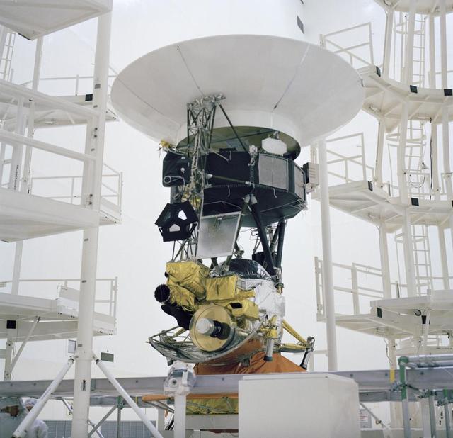
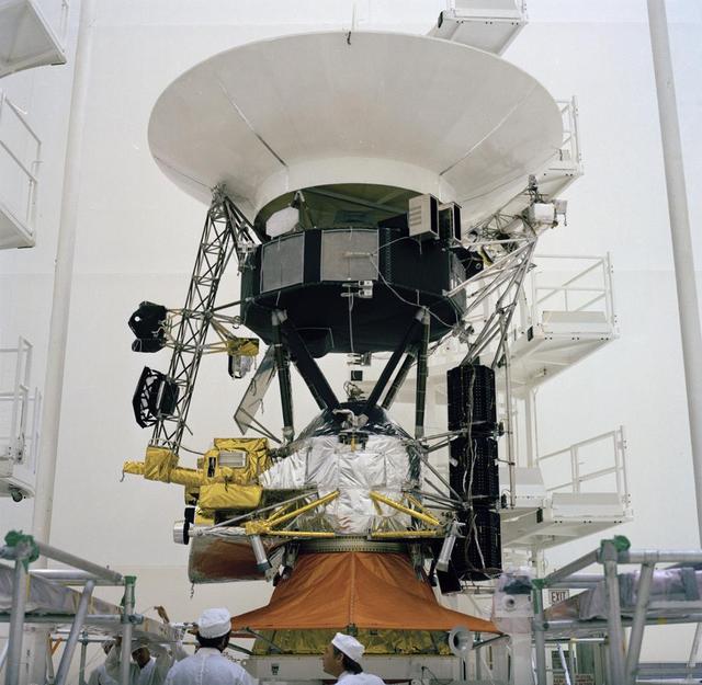
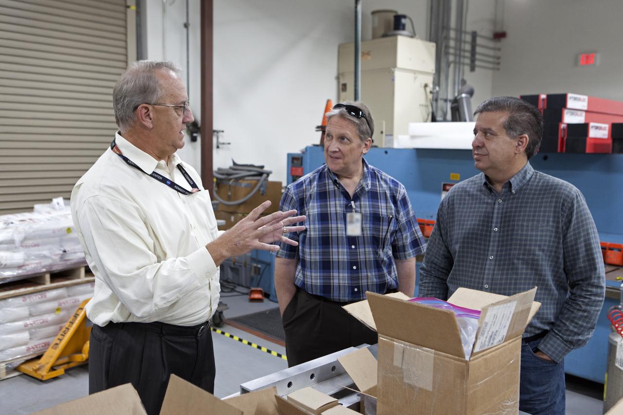
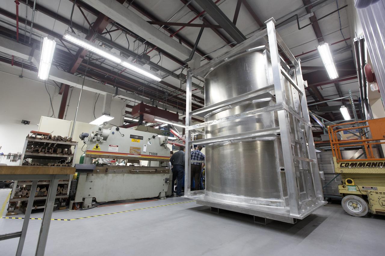
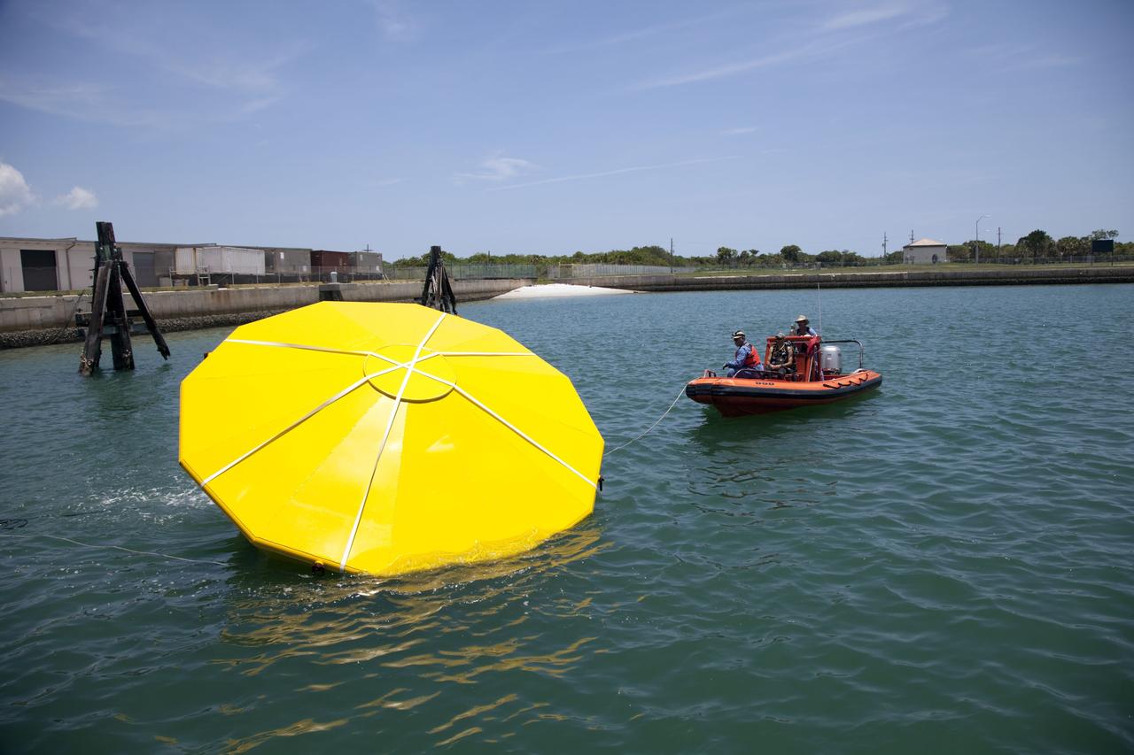
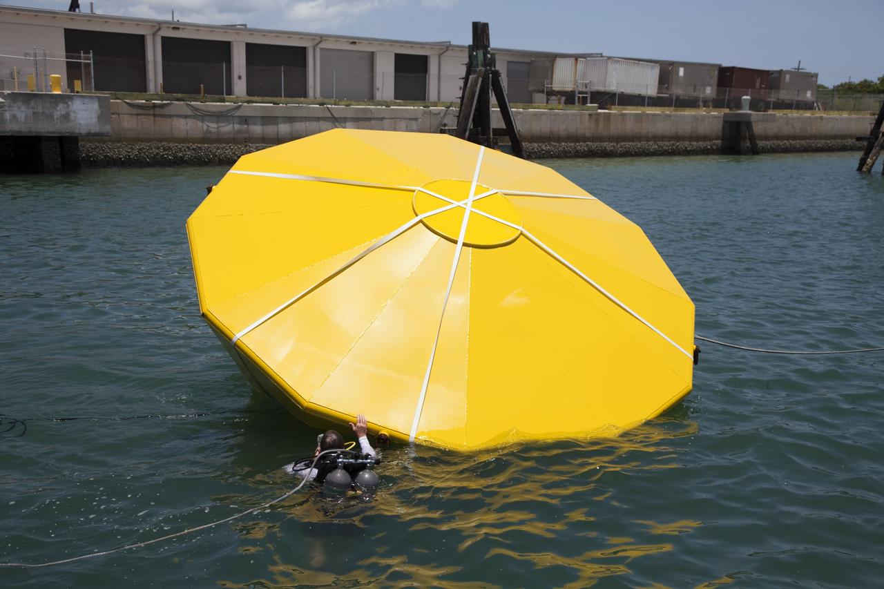
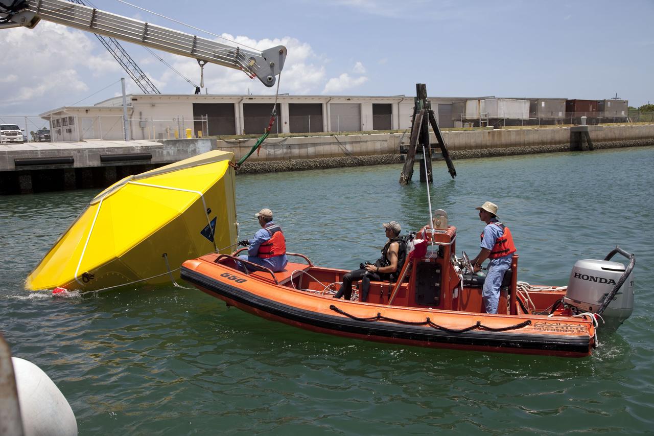
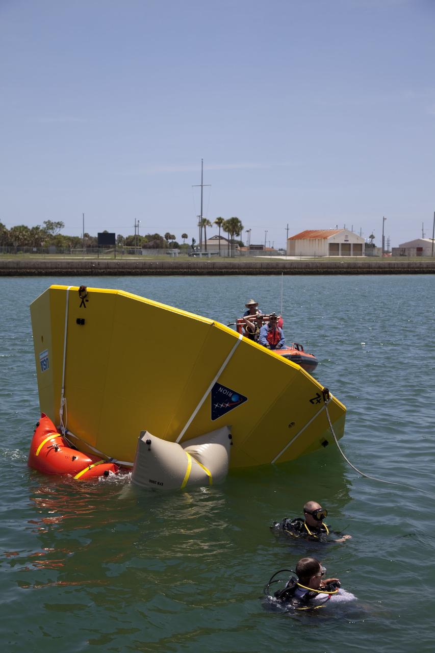
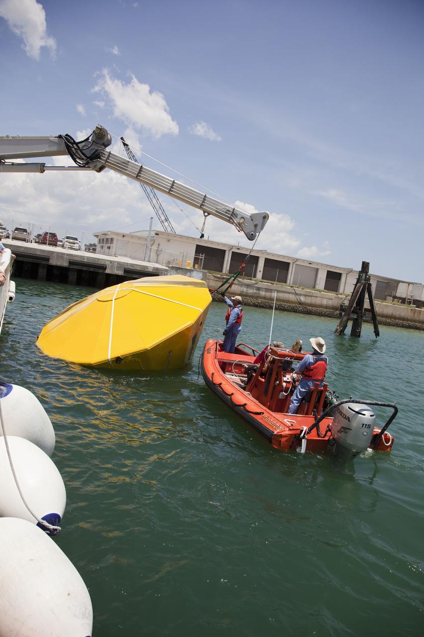
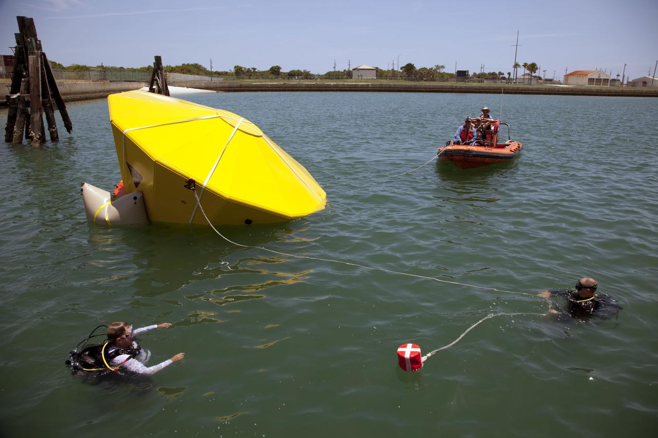
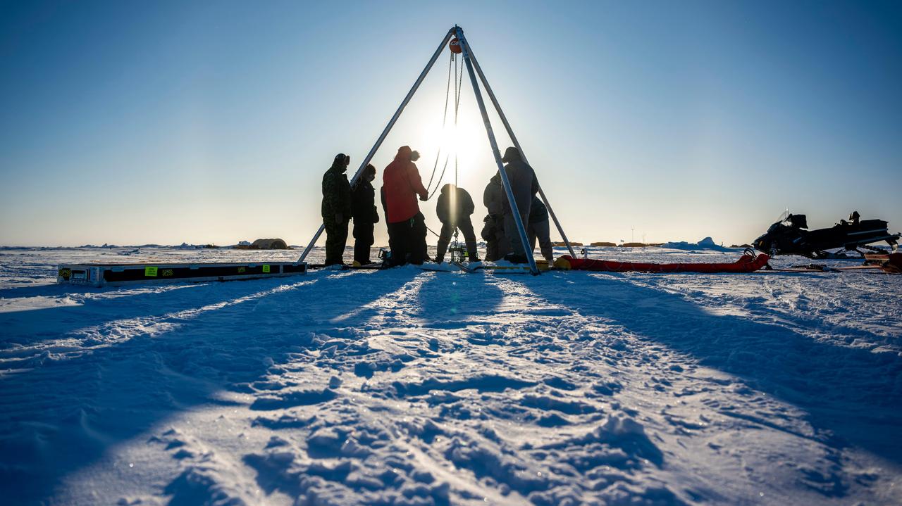
Arctic Test for JPL's IceNode Prototype
750 K motor test firing at Marshall's Test Stand 116 developing 650 pounds of thrust. The motor was tested for the Air Force Expendable Launch Vehicle (ELV) project.
Around Marshall
750 K motor test firing at Marshall's Test Stand 116 developing 650 pounds of thrust. The motor was tested for the Air Force Expendable Launch Vehicle (ELV) project.
Around Marshall
ISS018-E-033818 (19 Feb. 2009) --- Astronaut Michael Fincke, Expedition 18 commander, removes, cleans and replaces electronic test components on a single test card using Component Repair Equipment (CRE-1) hardware in a portable glovebox facility in the Harmony node of the International Space Station. Fincke unsoldered 1 1/2 components from an integrated circuit board and re-soldered new components including an integrated circuit chip.
Expedition 18 Station Development Test Objectives (STDO) Session 1
ISS018-E-033816 (19 Feb. 2009) --- Astronaut Michael Fincke, Expedition 18 commander, removes, cleans and replaces electronic test components on a single test card using Component Repair Equipment (CRE-1) hardware in a portable glovebox facility in the Harmony node of the International Space Station. Fincke unsoldered 1 1/2 components from an integrated circuit board and re-soldered new components including an integrated circuit chip.
Expedition 18 Station Development Test Objectives (STDO) Session 1
Students from Eau Gallie High School in Melbourne, Florida, visited the Prototype Development Laboratory at NASA’s Kennedy Space Center in Florida on Monday, April 28, 2025. The STEM participants have an interest in technical trades and learned about the technicians at the Prototype Development Laboratory who design, fabricate, and test protypes, test articles, and test support equipment.
STEM Students Visit KSC
This archival image was released as part of a gallery comparing JPL's past and present, commemorating the 80th anniversary of NASA's Jet Propulsion Laboratory on Oct. 31, 2016.  During World War II, the Jet Propulsion Laboratory had a contract with the U.S. Army to develop rocket torpedoes. This picture from August 1944 shows the test facility, known as the "Tow Channel." It was used for storage for many years before being torn out to make space for the Earth and Space Science Laboratory (Building 300) and the Microdevices Laboratory (Building 302).   http://photojournal.jpl.nasa.gov/catalog/PIA21124
The Tow Channel
The work was among 25 projects funded by NASA’s Mars Exploration Program this past year to push the limits of future technologies. Sand dunes confused the navigation algorithm of the Ingenuity Mars helicopter during several of its last flights, including its 72nd and final flight on the Red Planet in January 2024. The navigation software in development would help future rotorcraft track the surface of especially bland, featureless terrain similar to the barren Dumont Dunes. Tests also included flights over a region in Death Valley called Mars Hill, which is littered with rubbly volcanic rocks and has been used by NASA’s Mars researchers since the 1970s, during preparations for the Viking lander missions.
Researchers Test Mars Drone Software in Death Valley
The synthetic aperture radar pod developed by JPL is slung beneath NASA's Gulfstream-III research testbed during flight tests.
ED07-0027-45
Vibration test of the Orion Service Module advanced development propellant isolation valve.  "X: Angle of Rotation".
GRC-2008-C-00240
Test of bearing and seal materials in order to develop improved life bearing designs for operating in liquid turbomachinery.
Around Marshall
Abbigail Waddell and Nathaniel Boisjolie-Gair test a pressure system they and other students developed for the subscale Prandtl-D 3C glider.
Student Developed Aircraft System Provides Vital Data
Test of bearing and seal materials in order to develop improved life bearing designs for operating in liquid turbomachinery.
Around Marshall