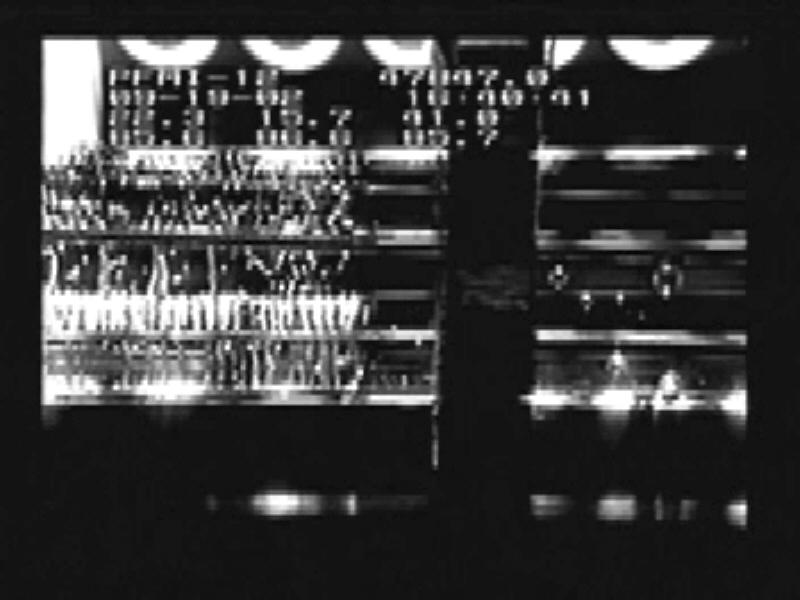
Video images sent to the ground allow scientists to watch the behavior of the bubbles as they control the melting and freezing of the material during the Pore Formation and Mobility Investigation (PFMI) in the Microgravity Science Glovebox aboard the International Space Station. While the investigation studies the way that metals behave at the microscopic scale on Earth -- and how voids form -- the experiment uses a transparent material called succinonitrile that behaves like a metal to study this problem. The bubbles do not float to the top of the material in microgravity, so they can study their interactions.
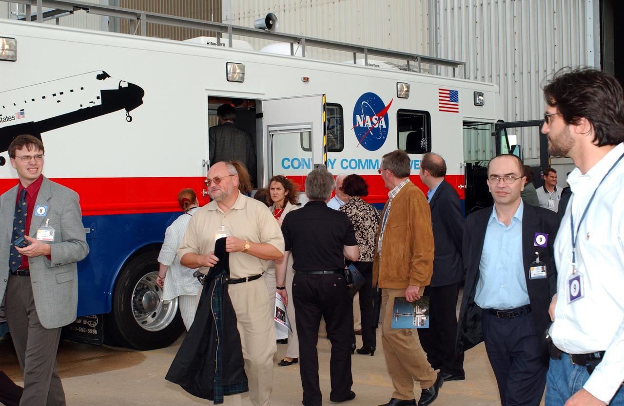
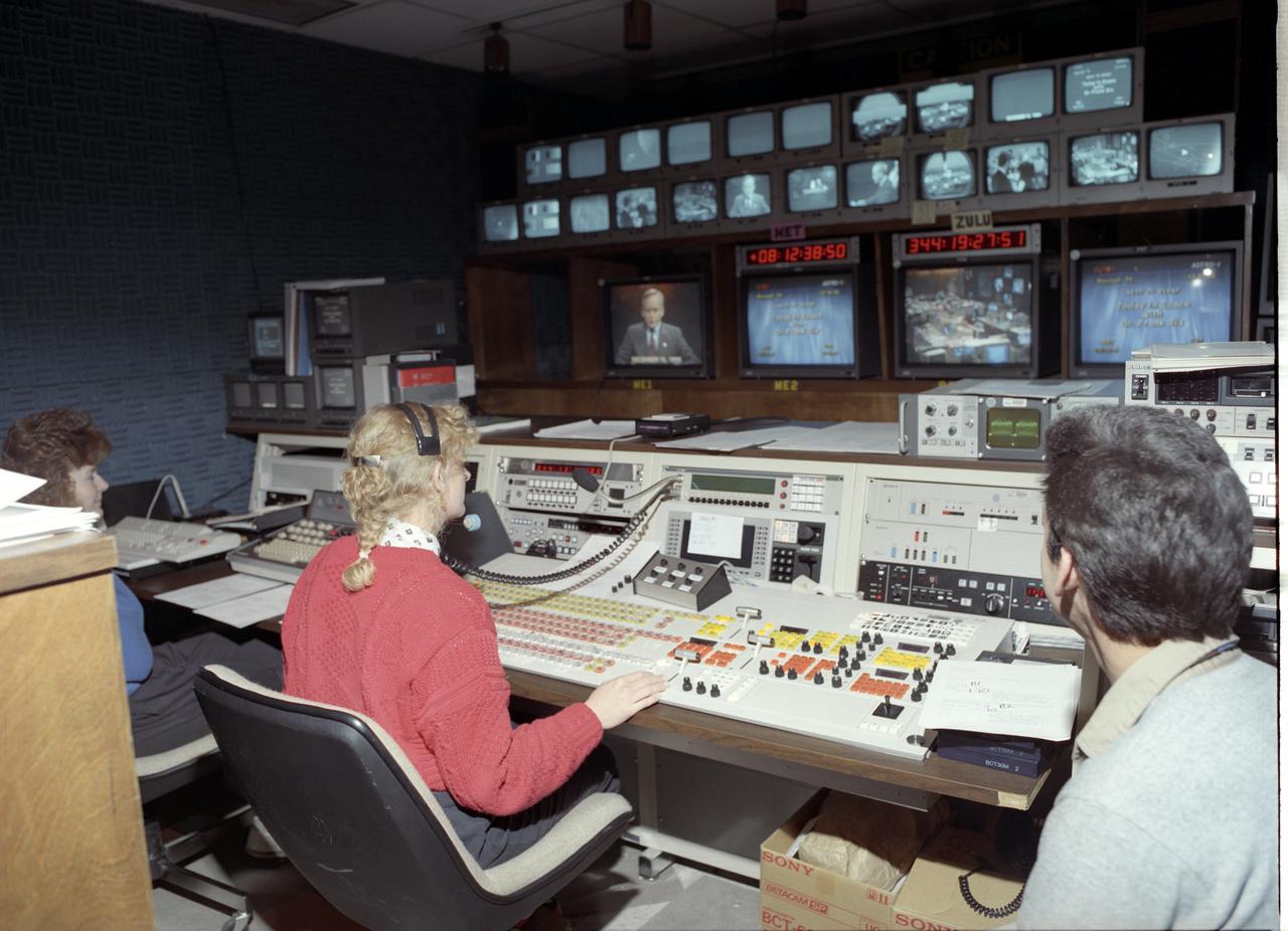
KENNEDY SPACE CENTER, FLA. - During their tour of KSC, members of the North American Treaty Organization (NATO) Parliamentary Assembly visit the Convoy Command Center, the prime vehicle to control critical communications between the orbiter, the crew and the Launch Control Center after a Shuttle landing, to monitor the health of the Shuttle Orbiter systems and to direct convoy operations at the Shuttle Landing Facility. The Parliamentarians are meeting in Orlando this year for their 49th annual gathering. They chose to visit KSC with their families during their one-day excursion break from meetings.
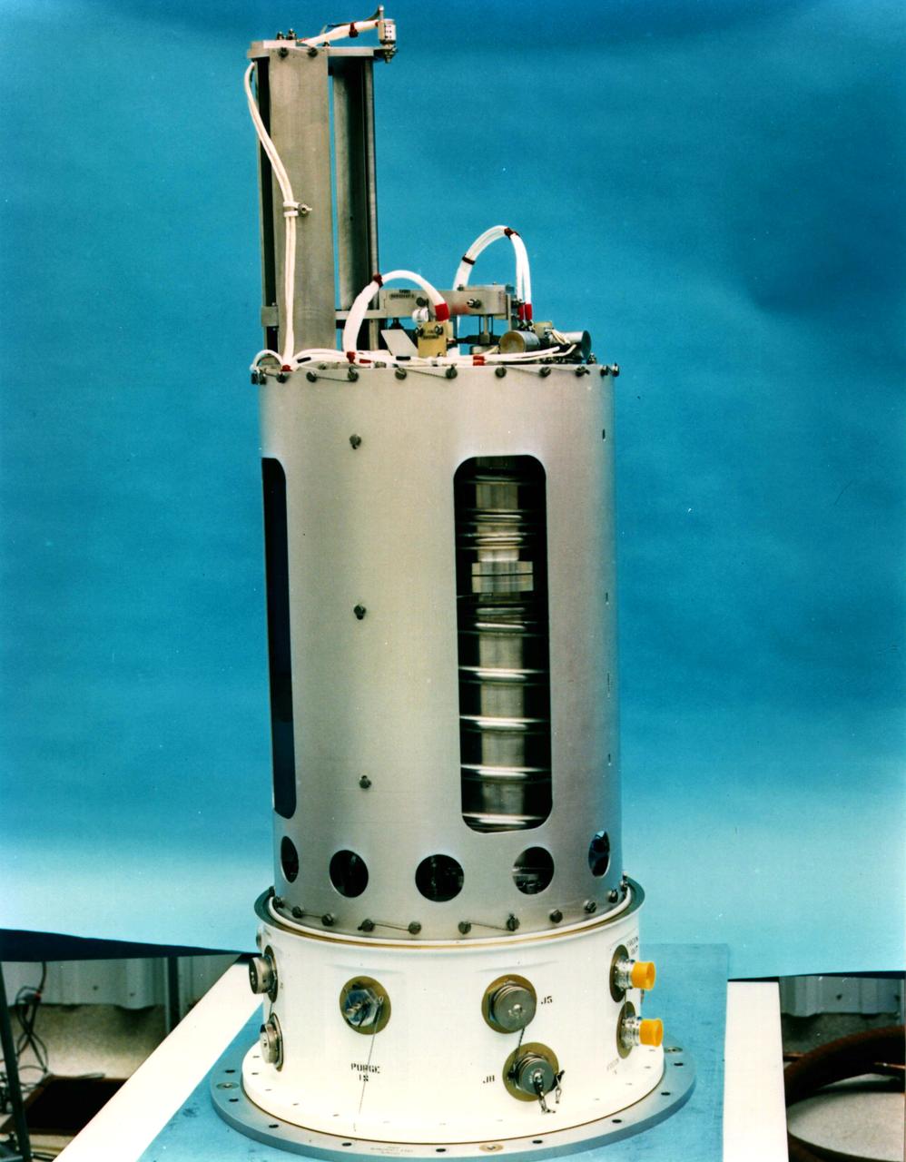
The Advanced Automated Directional Solidification Furnace (AADSF) with the Experimental Apparatus Container (EAC) removed flew during the USMP-2 mission. During USMP-2, the AADSF was used to study the growth of mercury cadmium telluride crystals in microgravity by directional solidification, a process commonly used on earth to process metals and grow crystals. The furnace is tubular and has three independently controlled temperature zones . The sample travels from the hot zone of the furnace (1600 degrees F) where the material solidifies as it cools. The solidification region, known as the solid/liquid interface, moves from one end of the sample to the other at a controlled rate, thus the term directional solidification.
The Advanced Automated Directional Solidification Furnace (AADSF) flew during the USMP-2 mission. During USMP-2, the AADSF was used to study the growth of mercury cadmium telluride crystals in microgravity by directional solidification, a process commonly used on earth to process metals and grow crystals. The furnace is tubular and has three independently controlled temperature zones. The sample travels from the hot zone of the furnace (1600 degrees F) where the material solidifies as it cools. The solidification region, known as the solid/liquid interface, moves from one end of the sample to the other at a controlled rate, thus the term directional solidification.
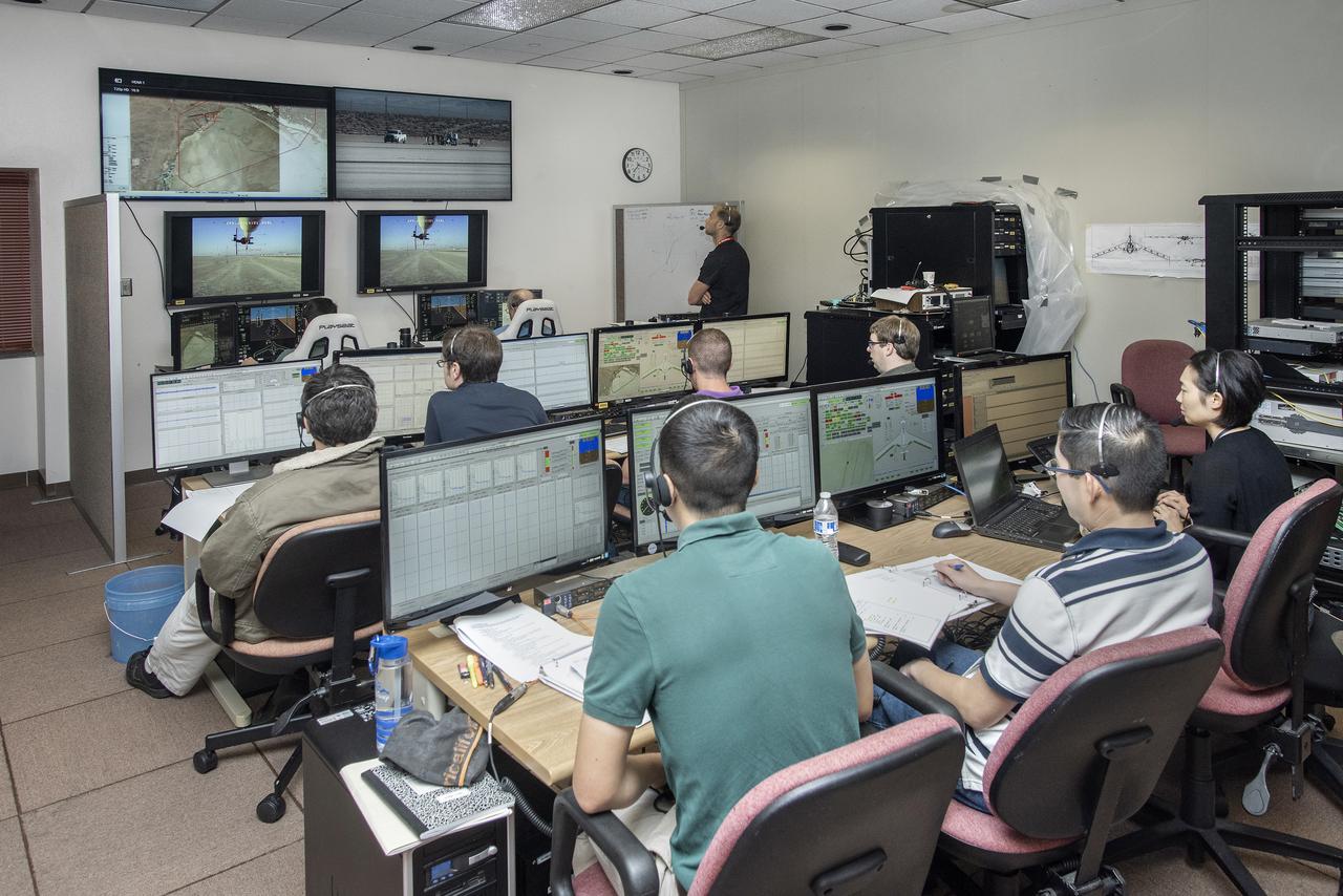
The control room for the remotely piloted X-56A has a feature that most do not – the pilot and co-pilot are in the front of the room, seen at left. The X-56A team has successfully suppressed flutter, which is a potentially destructive oscillation, with a classical and a modern controller. The controllers are essentially mathematical ways of directing the aircraft.

This is the 3rd entry of the TTBW model in 14x22. This test specifically is a lateral-directional test looking at the effects of 3D printed ventral, keel, and dorsal strakes on the stability and control characteristics of the model. Cooperative agreement between Boeing and NASA.
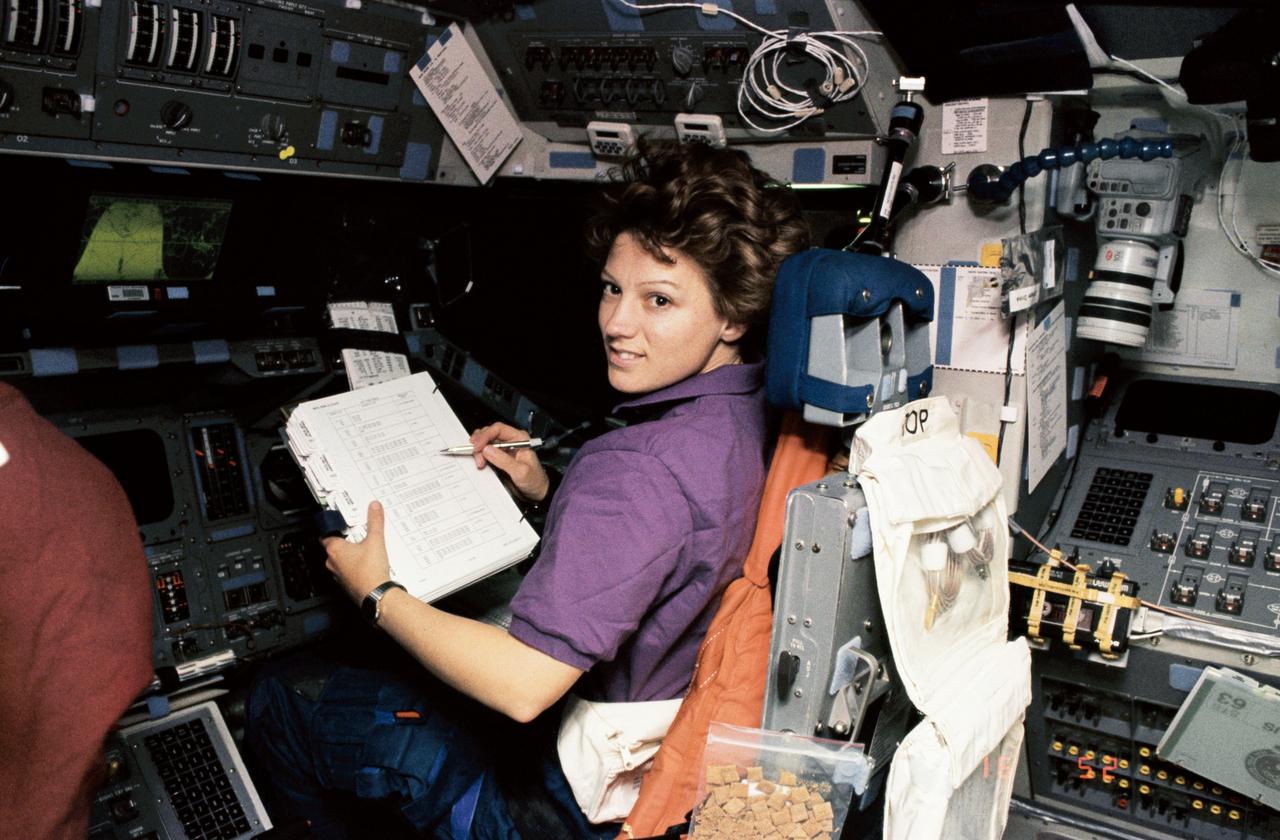
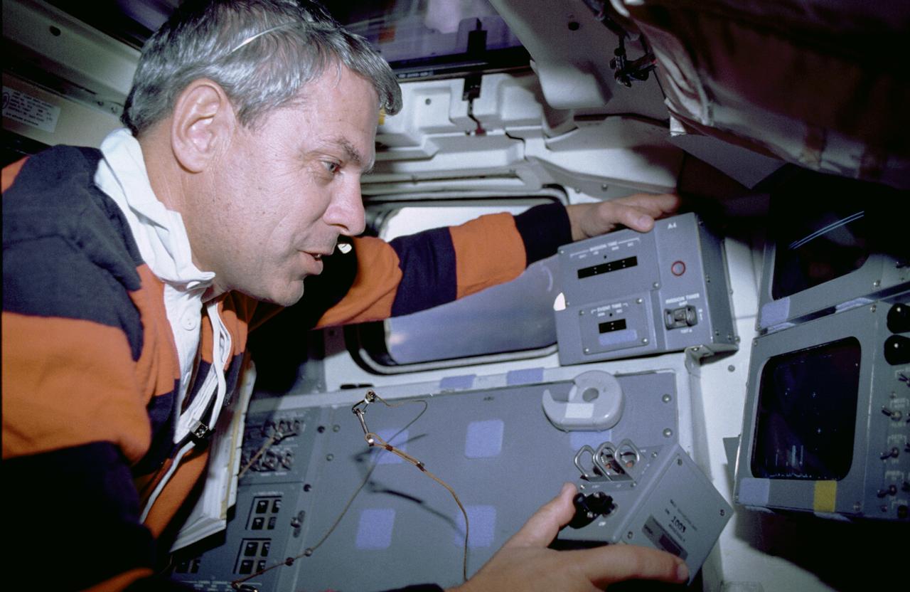
STS063-312-020 (3-11 Feb. 1995) --- Astronaut Eileen M. Collins, pilot, at the pilot's station during "hotfiring" procedure to clear leaking thruster prior to rendezvous with Russia's Mir Space Station. Others onboard the Space Shuttle Discovery were astronauts James D. Wetherbee, mission commander; Bernard A. Harris, Jr., payload commander; mission specialists C. Michael Foale and Janice E. Voss, and cosmonaut Vladimir G. Titov. This is one of 16 still photographs released by the NASA Johnson Space Center (JSC) Public Affairs Office (PAO) on February 14, 1995.
A photo of the control stick used on the Iron Cross Attitude Simulator. Although it resembled today's desktop computer flight sticks, its operation was different. As with a standard control stick, moving it back and forth raised and lowered the nose resulting in changes in pitch. Moving the stick to the right or left raised or lowered the wing, resulted in changes in roll. This control stick had a third axis, not found in standard control sticks. Twisting the stick to the right or left caused the airplane's nose to move horizontally in the same direction, resulting in changes in yaw.
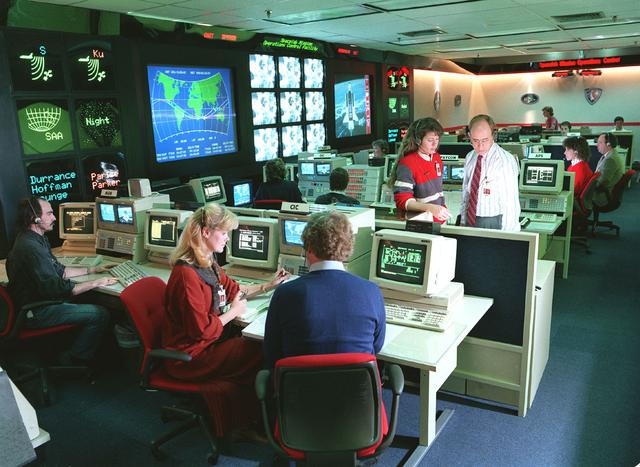
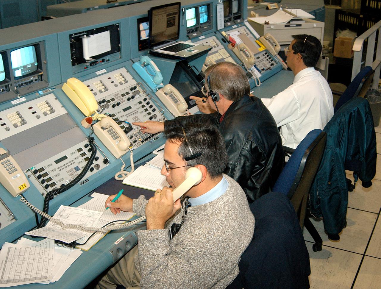
JSC2001-E-21328 (12 July 2001) --- Flight director LeRoy Cain directs his attention to data related to the Space Shuttle Atlantis and its impending launch from the Kennedy Space Center (KSC) several hundred miles away from this Houston setting at the Johnson Space Center's Mission Control Center (MCC). As soon as the vehicle cleared the tower in Florida, the Houston-based team of flight controllers took over the ground control of the flight.
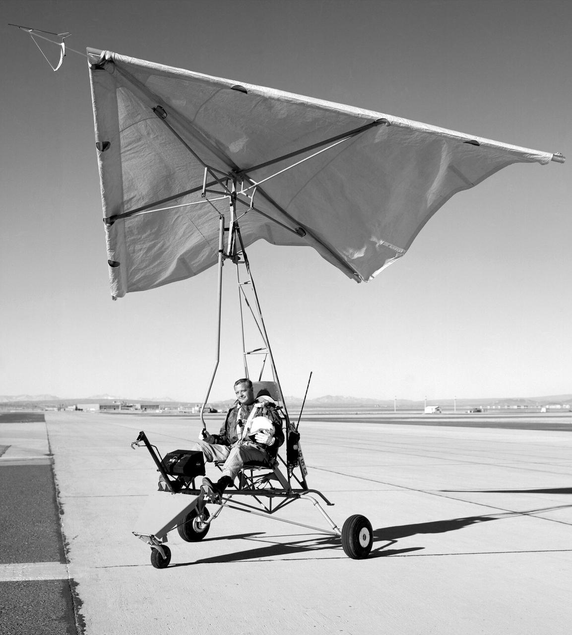
Test pilot Milton Thompson sitting in NASA Flight Research Center-built Paresev 1 (Paraglider Research Vehicle) on the taxi strip in front of the NASA Flight Research Center in 1962. In this photo the control stick can be seen coming from overhead and hanging in front of the pilot. The control system was a direct link with the wing membrane made of doped Irish linen. By maintaining simplicity during construction, it was possible to make control and configuration changes overnight and, in many instances, in minutes.
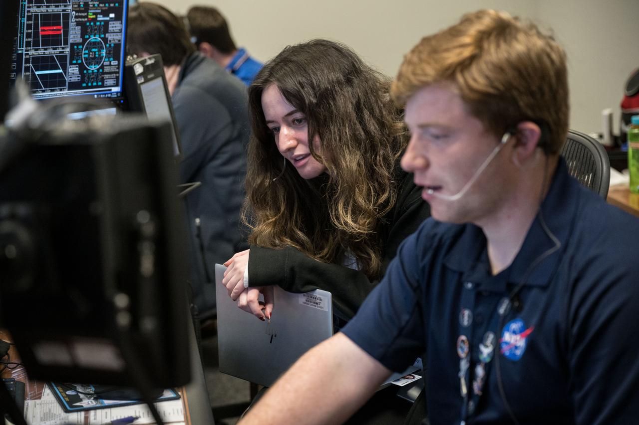
jsc2022e090764 (Dec. 1, 2022): Flight controller Jason Helms at the guidance, navigation and control console in Houston’s Mission Control Center observes the Orion spacecraft under the direction of Flight Director Rick LaBrode. The spacecraft departed its distant retrograde orbit on flight day 16 of the Artemis I mission – one of the steps needed to bring the spacecraft home from the Moon. Credit: NASA/Robert Markowitz
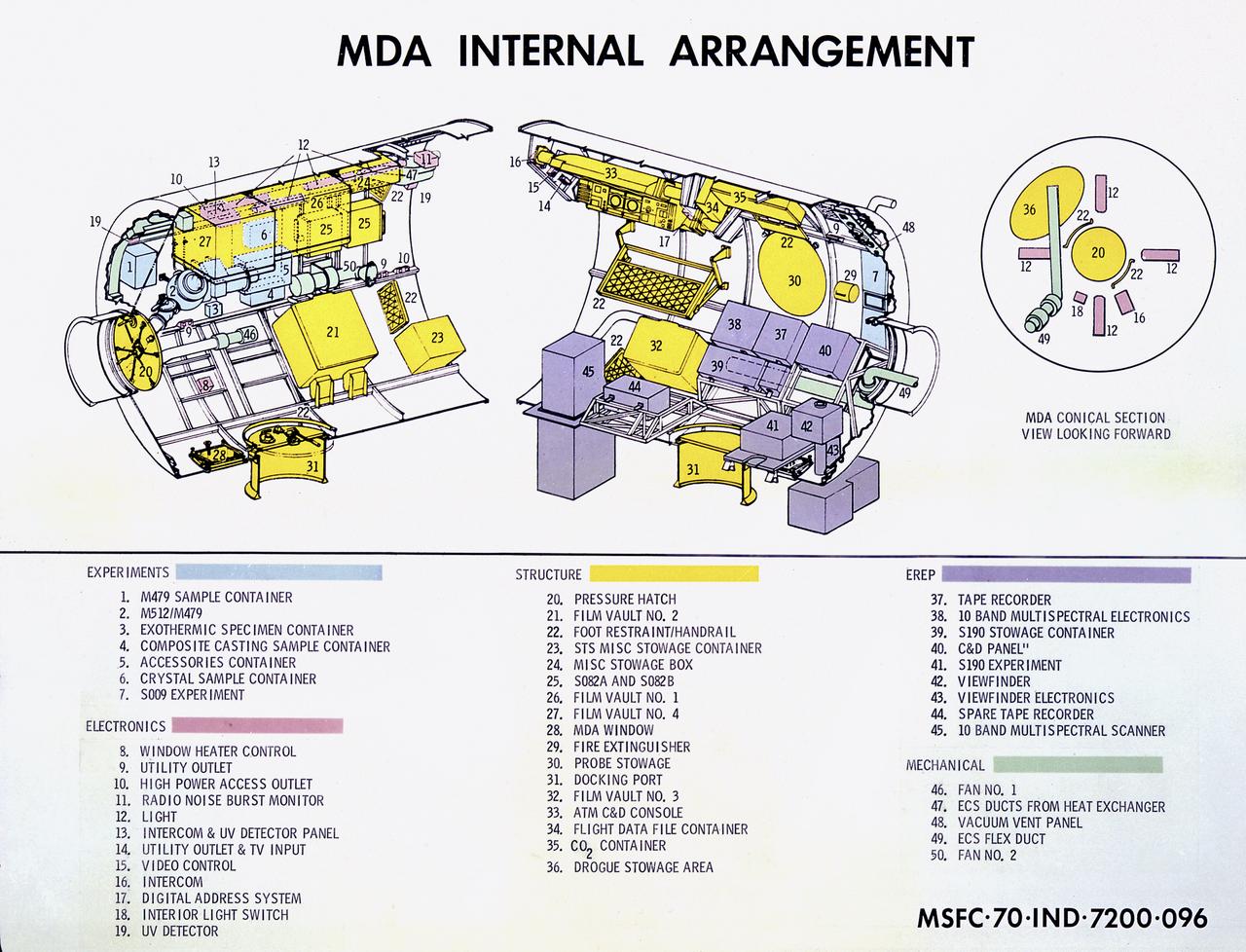
This cutaway drawing details the internal design of the Skylab Multiple Docking Adapter (MDA). The MDA, built under the direction of the Marshall Space Flight Center, housed various Skylab control and experiment units, and provided a docking port for the Apollo Command Module (CM).
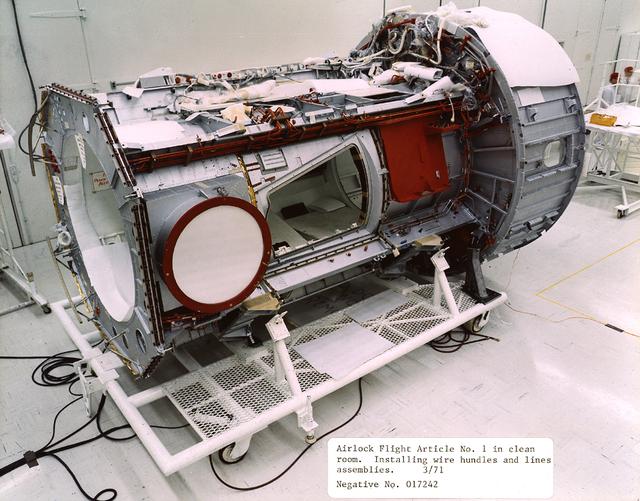
This 1971 photograph was taken during the assembly of the Flight Article of the Skylab Airlock Module (AM). The Am, fabricated by McDornell Douglas under the direction of the Marshall Flight Center, allowed Skylab crew members an exit to perform extravehicular activities. The Module also contained many of the supplies and control panels for electrical power distribution and internal environment.
jsc2022e090101 (Nov. 28, 2022): Flight controllers observe the Orion spacecraft under the direction of Flight Director Paul Konyha. The spacecraft reached its maximum distance from the Earth on flight day 14 of the Artemis I mission, flying nearly 270,000 miles away from the Earth. Credit: NASA/Robert Markowitz
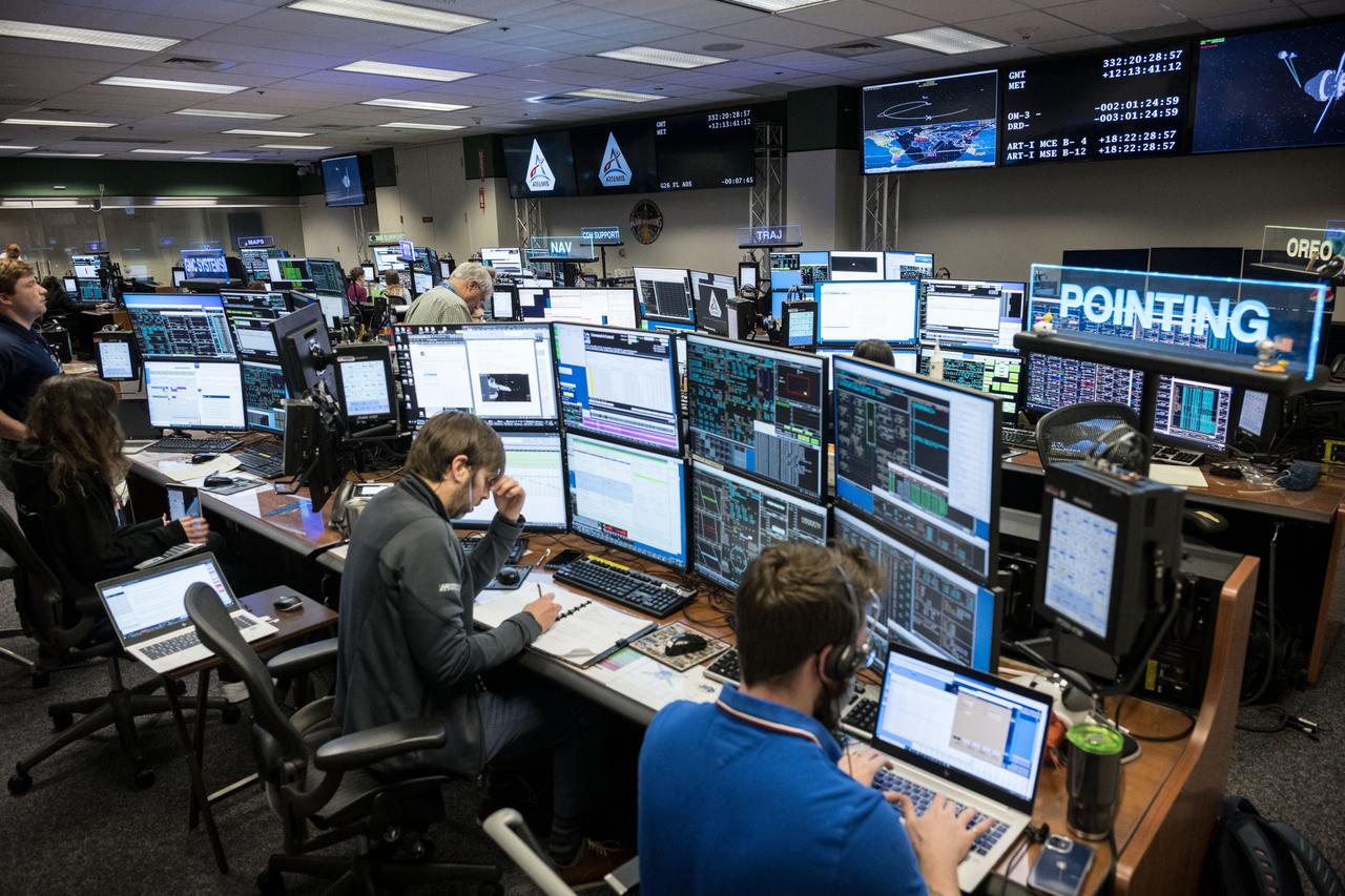
jsc2022e090102 (Nov. 28, 2022): Flight controllers observe the Orion spacecraft under the direction of Flight Director Paul Konyha. The spacecraft reached its maximum distance from the Earth on flight day 14 of the Artemis I mission, flying nearly 270,000 miles away from the Earth. Credit: NASA/Robert Markowitz
jsc2022e090747 (Dec. 1, 2022): Flight controllers Doug Haskovec and Amar Ollero at the mechanical and power officer console in Houston’s Mission Control Center observe the Orion spacecraft under the direction of Flight Director Rick LaBrode. The spacecraft departed its distant retrograde orbit on flight day 16 of the Artemis I mission – one of the steps needed to bring the spacecraft home from the Moon. Credit: NASA/Robert Markowitz
During the final phase of tests with the HARV, Dryden technicians installed nose strakes, which were panels that fitted flush against the sides of the forward nose. When the HARV was at a high alpha, the aerodynamics of the nose caused a loss of directional stability. Extending one or both of the strakes results in strong side forces that, in turn, generated yaw control. This approach, along with the aircraft's Thrust Vectoring Control system, proved to be stability under flight conditions in which conventional surfaces, such as the vertical tails, were ineffective.
jsc2022e090753 (Dec. 1, 2022): Flight controller Julie Reed at the flight dynamics officer console in Houston’s Mission Control Center observes the Orion spacecraft under the direction of Flight Director Rick LaBrode. The spacecraft departed its distant retrograde orbit on flight day 16 of the Artemis I mission – one of the steps needed to bring the spacecraft home from the Moon. Credit: NASA/Robert Markowitz
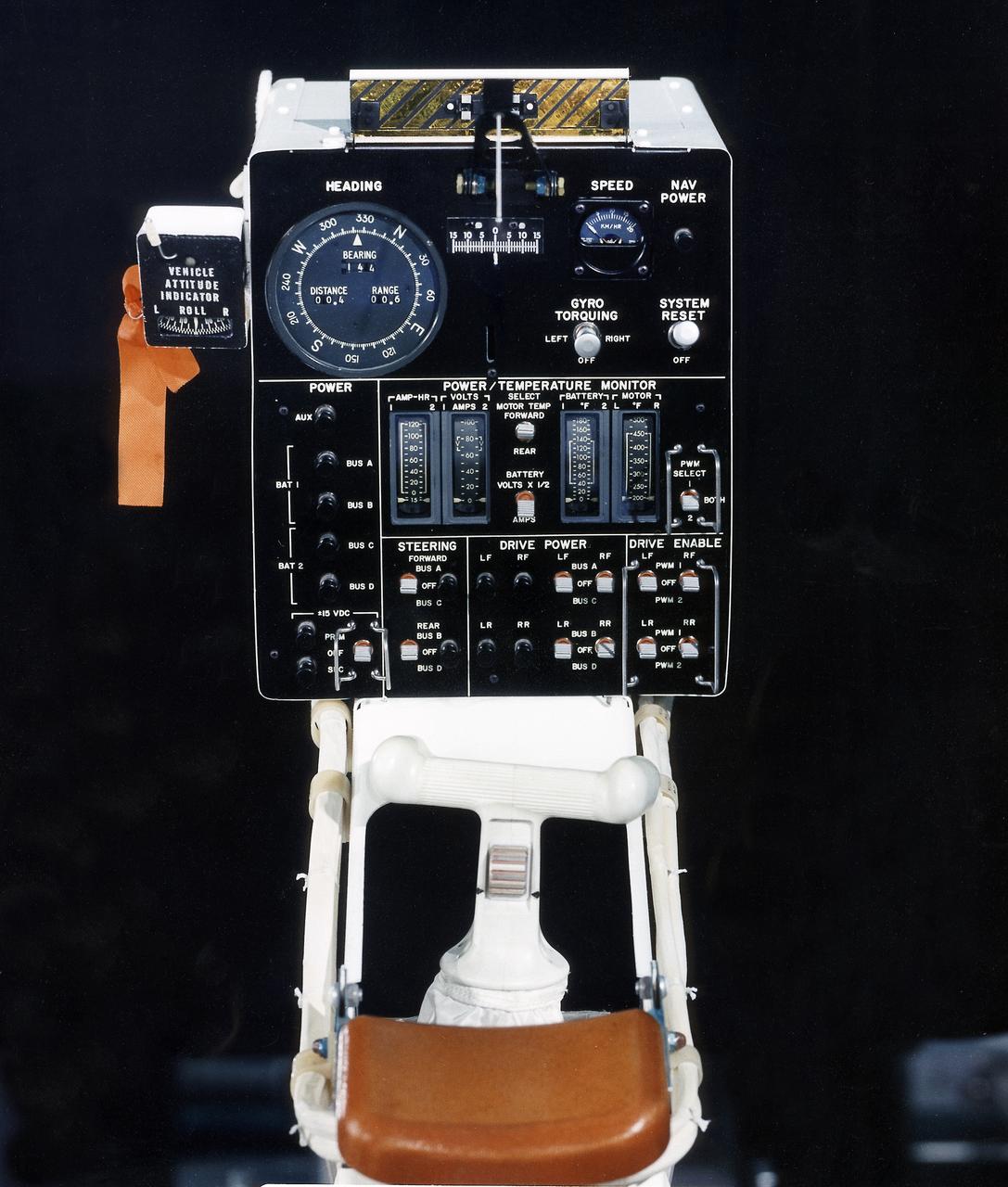
This photograph is a view of a display, control console, and hand controller for the Lunar Roving Vehicle (LRV) No. 2. The LRV was built to give Apollo astronauts a greater range of mobility during lunar exploration. It was an open-space and collapsible vehicle about 10 feet long with large mesh wheels, anterna, appendages, tool caddies, and camera. An LRV was used on each of the last three Apollo missions; Apollo 15, Apollo 16, and Apollo 17. It was built by the Boeing Company under the direction of the Marshall Space Flight Center.
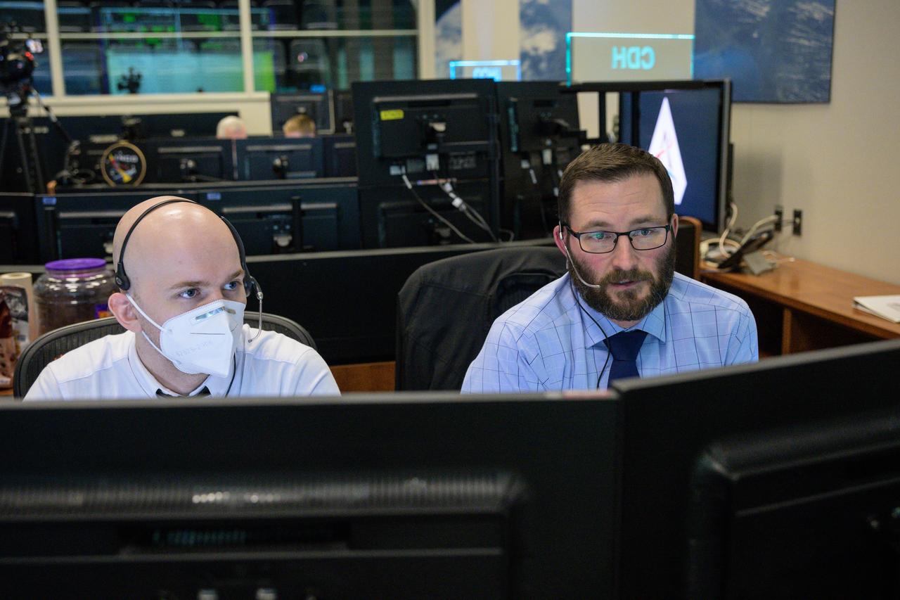
jsc2022e090746 (Dec. 1, 2022): Flight controller Todd Quasny at the command and data handling console in Houston’s Mission Control Center observes the Orion spacecraft under the direction of Flight Director Rick LaBrode. The spacecraft departed its distant retrograde orbit on flight day 16 of the Artemis I mission – one of the steps needed to bring the spacecraft home from the Moon. Credit: NASA/Robert Markowitz
jsc2022e090759 (Dec. 1, 2022): Flight controllers Steve Sides and Brian Crisp at the instrumentation and communications officer console in Houston’s Mission Control Center observe the Orion spacecraft under the direction of Flight Director Rick LaBrode. The spacecraft departed its distant retrograde orbit on flight day 16 of the Artemis I mission – one of the steps needed to bring the spacecraft home from the Moon. Credit: NASA/Robert Markowitz
jsc2022e090757 (Dec. 1, 2022): Flight controller Joel Appel (right) at the propulsion console in Houston’s Mission Control Center observes the Orion spacecraft under the direction of Flight Director Rick LaBrode. The spacecraft departed its distant retrograde orbit on flight day 16 of the Artemis I mission – one of the steps needed to bring the spacecraft home from the Moon. Credit: NASA/Robert Markowitz
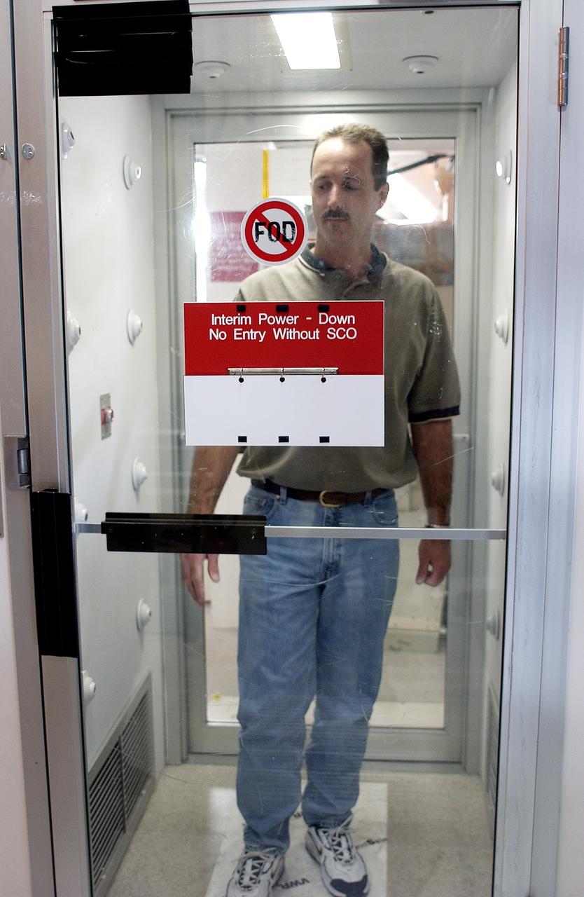
KENNEDY SPACE CENTER, FLA. - A KSC employee uses a clean-air shower before entering a clean room. Streams of pressurized air directed at the occupant from nozzles in the chamber's ceiling and walls are designed to dislodge particulate matter from hair, clothing and shoes. The adhesive mat on the floor captures soil from shoe soles, as well as particles that fall on its surface. Particulate matter has the potential to contaminate the space flight hardware being stored or processed in the clean room. The shower is part of KSC's Foreign Object Debris (FOD) control program, an important safety initiative.
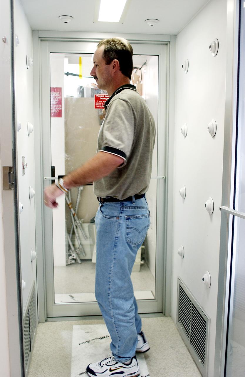
KENNEDY SPACE CENTER, FLA. - A KSC employee uses a clean-air shower before entering a clean room. Streams of pressurized air directed at the occupant from nozzles in the chamber's ceiling and walls are designed to dislodge particulate matter from hair, clothing and shoes. The adhesive mat on the floor captures soil from shoe soles, as well as particles that fall on its surface. Particulate matter has the potential to contaminate the space flight hardware being stored or processed in the clean room. The shower is part of KSC's Foreign Object Debris (FOD) control program, an important safety initiative.
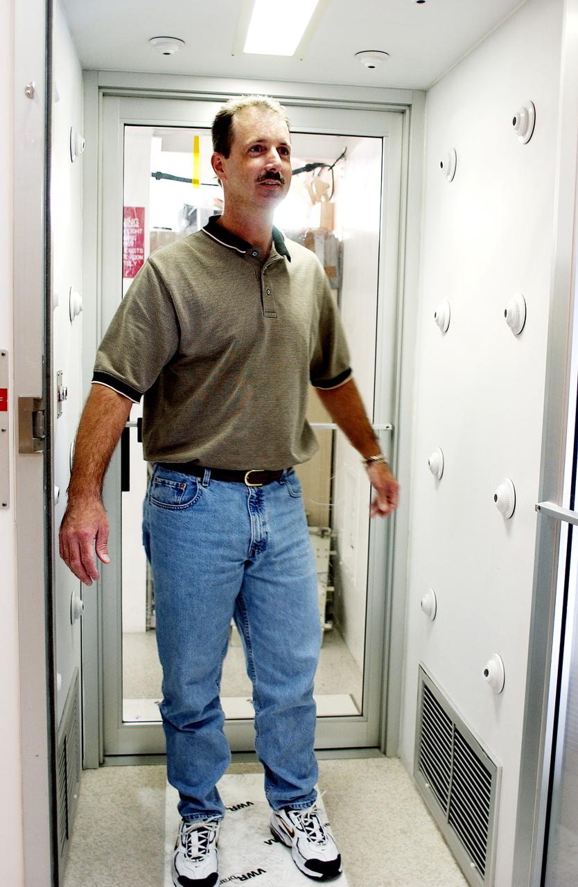
KENNEDY SPACE CENTER, FLA. - A KSC employee uses a clean-air shower before entering a clean room. Streams of pressurized air directed at the occupant from nozzles in the chamber's ceiling and walls are designed to dislodge particulate matter from hair, clothing and shoes. The adhesive mat on the floor captures soil from shoe soles, as well as particles that fall on its surface. Particulate matter has the potential to contaminate the space flight hardware being stored or processed in the clean room. The shower is part of KSC's Foreign Object Debris (FOD) control program, an important safety initiative.
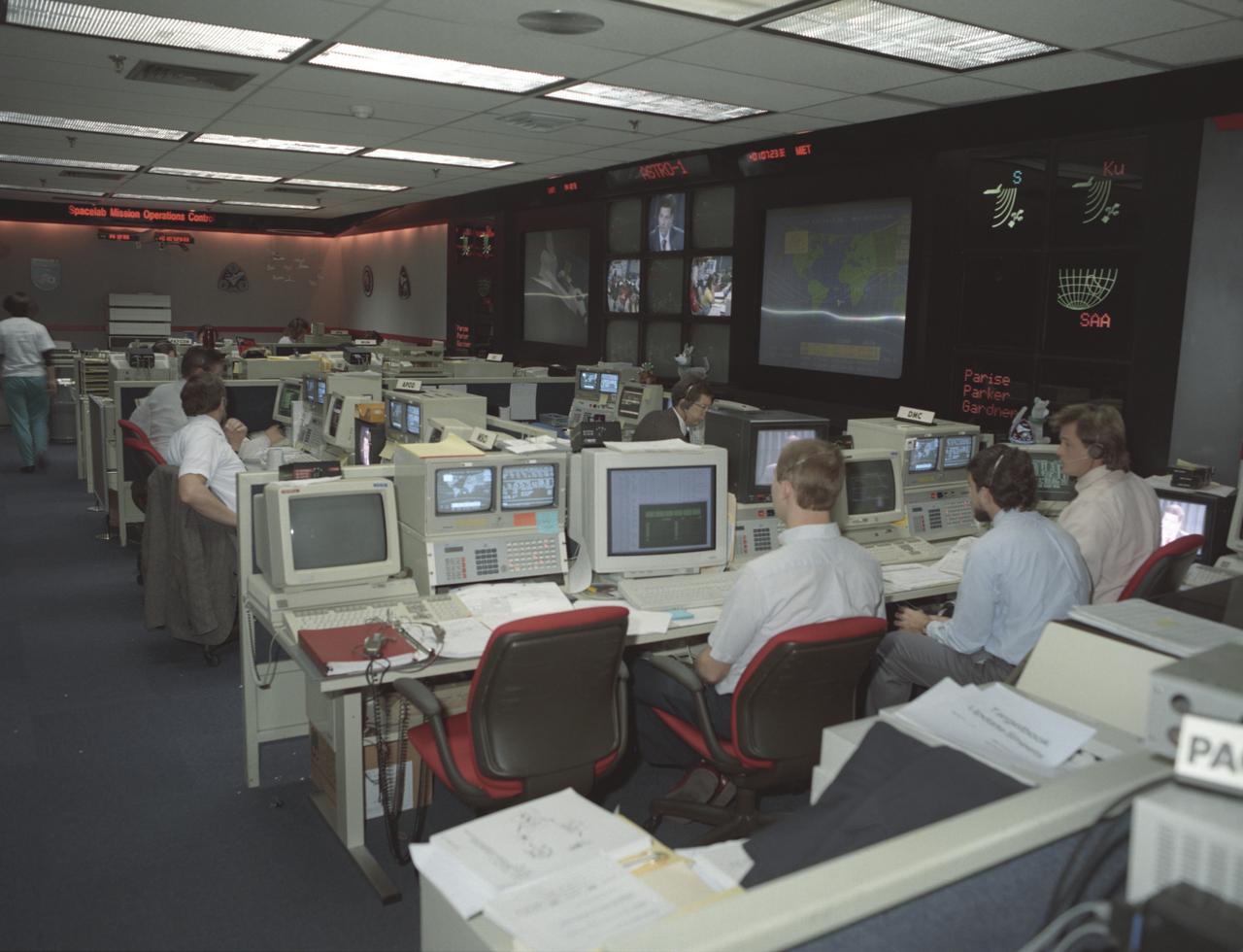
This photograph was taken during the Astro-1 mission (STS-35) showing activities at NASA's new Payload Operations Control Center (POCC) at the Marshall Space Flight Center. The POCC was the air/ground communication charnel used between the astronauts and ground control teams during the Spacelab missions. Teams of controllers and researchers directed on-orbit science operations, sent commands to the spacecraft, received data from experiments aboard the Space Shuttle, adjusted mission schedules to take advantage of unexpected science opportunities or unexpected results, and worked with crewmembers to resolve problems with their experiments.
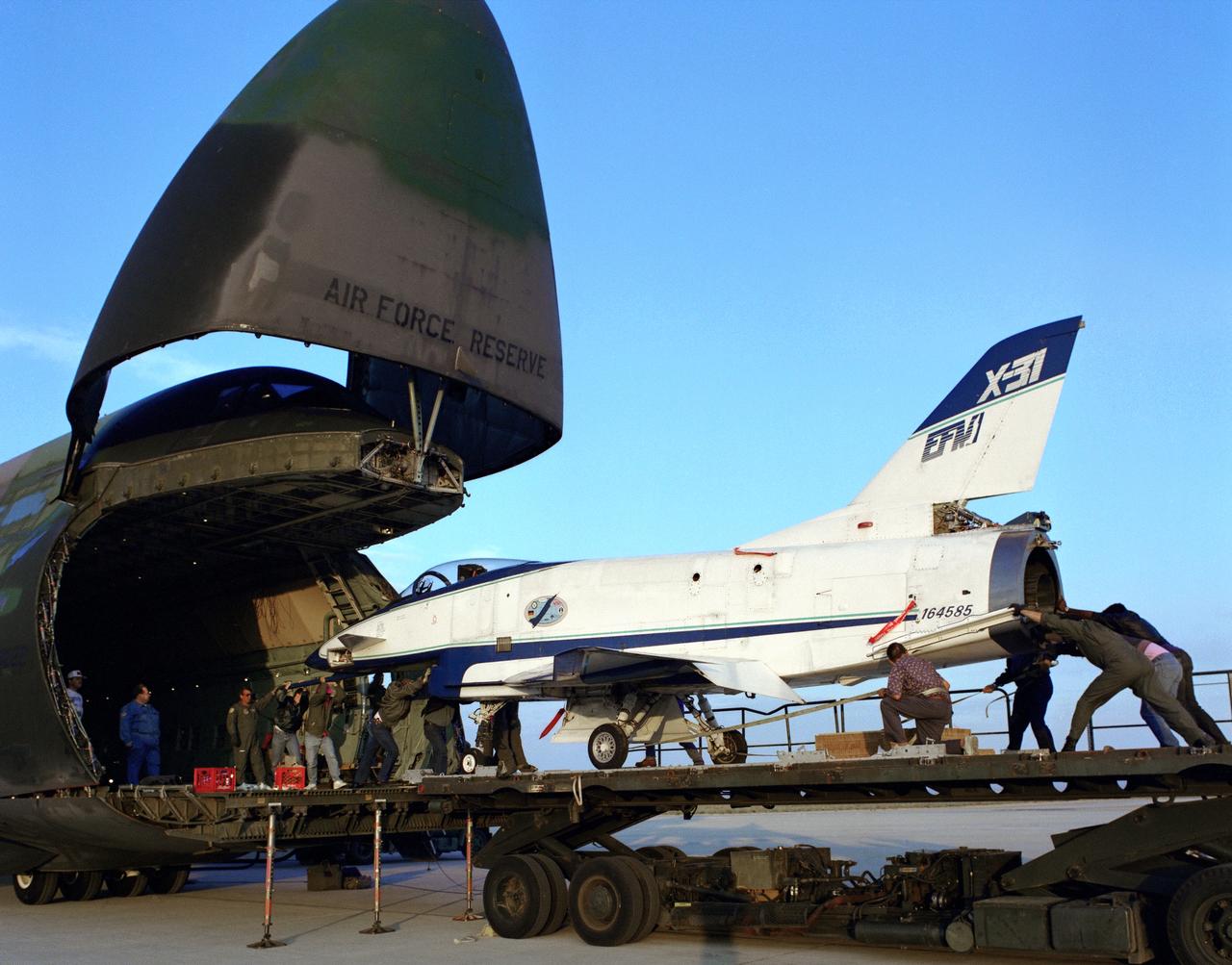
The X-31 Enhanced Fighter Maneuverability Technology Demonstrator Aircraft, based at the NASA Dryden Flight Research Center, Edwards, California, begins rolling aboard an Air Force Reserve C-5 transport which ferried it on May 22, 1995 to Europe where it was flown in the Paris Air Show in June 1995. To fit in the C-5 the right wing of the X-31 had to be removed. At the air show, the X-31 demonstrated the value of using thrust vectoring (directing engine exhaust flow) coupled with advanced flight control systems to provide controlled flight at very high angles of attack.
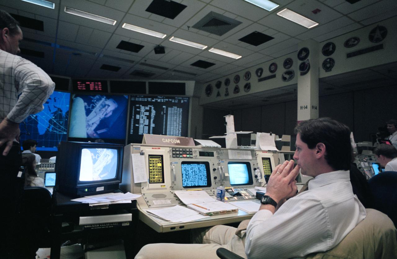
STS61-S-101 (8 Dec 1993) --- Astronaut Gregory J. Harbaugh, spacecraft communicator (CAPCOM), observes as two astronauts work through a lengthy period of extravehicular activity (EVA) in the cargo bay of the Earth-orbiting Space Shuttle Endeavour. Seen on the screen in the front of the flight control room, preparing to work with the Hubble Space Telescope's (HST) magnetometers, are astronauts F. Story Musgrave and Jeffrey A. Hoffman. Harbaugh stayed busy passing up flight controllers suggestions and directions during the record-breaking battery of in-space servicing sessions. Lead flight director Milt Heflin is partially visible at left edge of frame.
The modified F-18 High Alpha Research Vehicle (HARV) carries out air flow studies on a flight from the Dryden Flight Research Center, Edwards, California. Using oil, researchers were able to track the air flow across the wing at different speeds and angles of attack. A thrust vectoring system had been installed on the engines' exhaust nozzles for the high angle of attack research program. The thrust vectoring system, linked to the aircraft's flight control system, moves a set of three paddles on each engine to redirect thrust for directional control and increased maneuverability at angles of attack at up to 70 degrees.
Activities in the Spacelab Mission Operations Control facility at the Marshall Space Flight Center (MSFC) are shown in this photograph. All NASA Spacelab science missions were controlled from and the science astronauts were supported by this facility during the missions. Teams of flight controllers and researchers at the MSFC Space Mission Operations Control Center directed all NASA science operations, sent commands directly to the crew of Spacelab, and received and analyzed data from experiments on board the Spacelab. The facility used the air/ground communications charnels between the astronauts and ground control teams during the Spacelab missions. Spacelab science operations were a cooperative effort between the science astronaut crew in orbit and their colleagues in the Space Mission Operations Control Center. Though the crew and the instrument science teams were separated by many miles, they interacted with one another to evaluate observations and solve problems in much the same way as they would when working side by side in a ground-based laboratory. Most of the action was centered in two work areas: The payload control area from which the overall payload was monitored and controlled and the science operations area where teams of scientists monitored their instruments and direct experiment activities. This facility is no longer operational since the last Spacelab mission, U.S. Microgravity Payload-4 in December 1997, and has become one of the historical sites at MSFC. The facility was reopened as the International Space Station Payload Operations Center in March 2001.

Launch of a three-stage Vanguard (SLV-7) from Cape Canaveral, Florida, September 18, 1959. Designated Vanguard III, the 100-pound satellite was used to study the magnetic field and radiation belt. In September 1955, the Department of Defense recommended and authorized the new program, known as Project Vanguard, to launch Vanguard booster to carry an upper atmosphere research satellite in orbit. The Vanguard vehicles were used in conjunction with later booster vehicle such as the Thor and Atlas, and the technique of gimbaled (movable) engines for directional control was adapted to other rockets.
Mechanical engineering and integration technician, Lucas Keim, directs the crane operator from inside the thermal vacuum chamber in support of OSAM-1 environmental testing operations at Goddard Space Flight Center, Greenbelt Md., Nov 30, 2023. This photo has been reviewed by OSAM1 project management and the Export Control Office and is released for public view. NASA/Mike Guinto
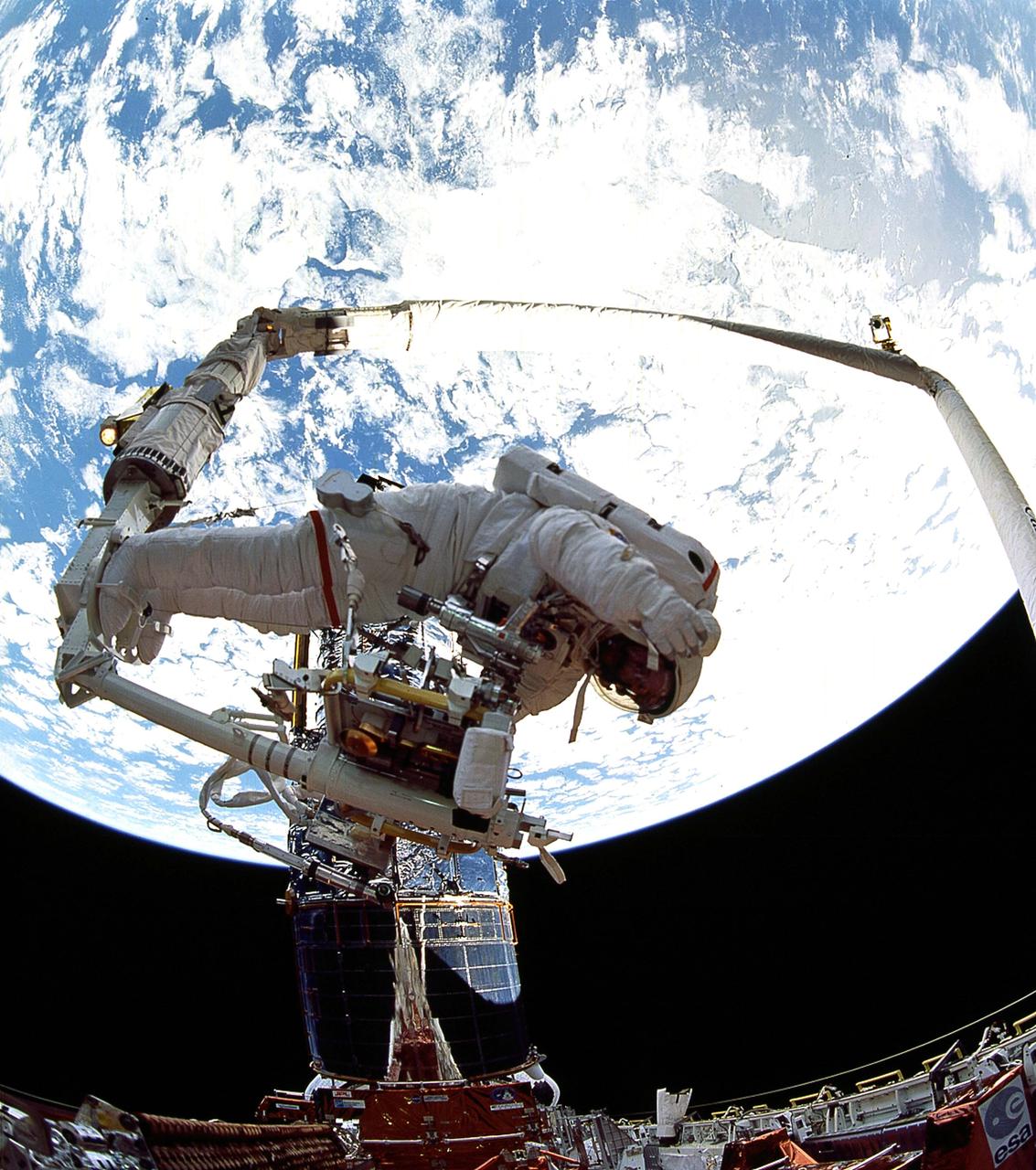
STS061-105-026 (7 Dec. 1993) --- Astronaut Jeffrey A. Hoffman signals directions to European Space Agency (ESA) astronaut Claude Nicollier, as the latter controls the Remote Manipulator System (RMS) arm during the third of five Extravehicular Activities (EVA) on the Hubble Space Telescope (HST) servicing mission. Astronauts Hoffman and F. Story Musgrave earlier changed out the Wide Field\Planetary Camera (WF\PC).
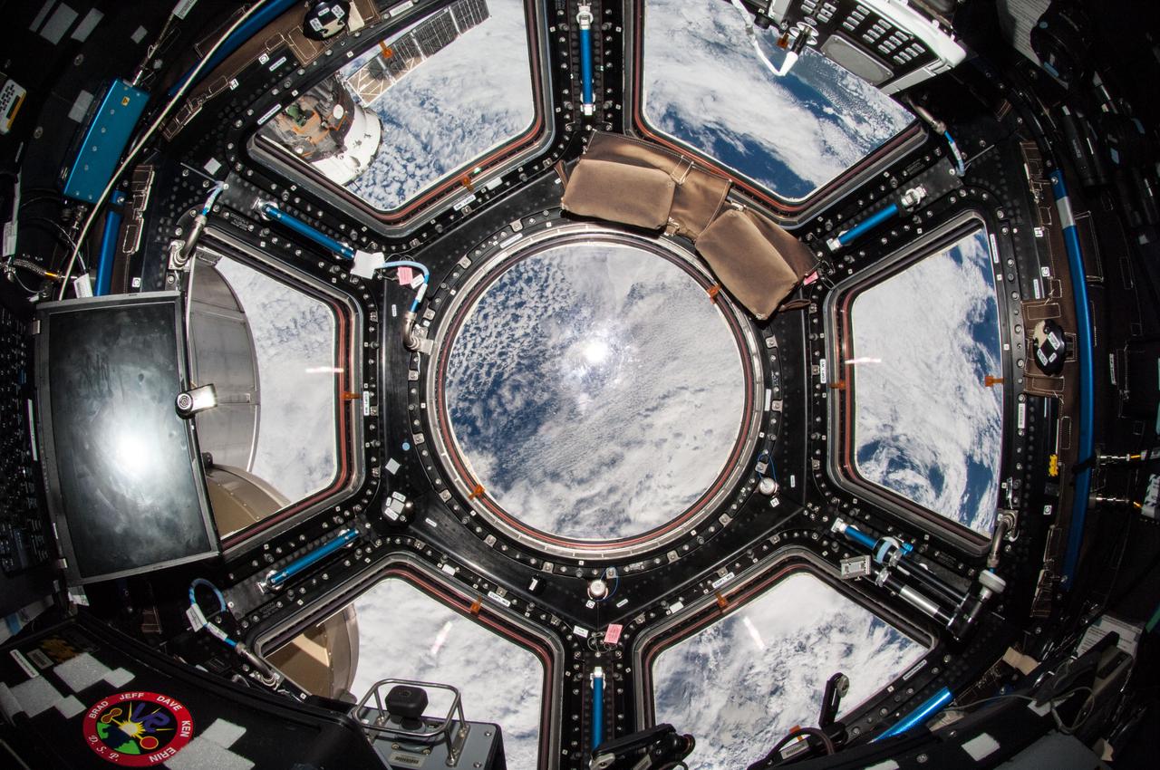
iss038e013587 (12/8/2013) --- A view of the Cupola module aboard the International Space Station (ISS). The cupola is a small module designed for the observation of operations outside the station such as robotic activities, the approach of vehicles, and spacewalks. Its six side windows and a direct nadir viewing window provide spectacular views of Earth and celestial objects. The windows are equipped with shutters to protect them from contamination and collisions with orbital debris or micrometeorites. The cupola house the robotic workstation that controls the Canadarm2.
The Multiple Docking Adapter (MDA), designed and constructed under the direction of the Marshall Space Flight Center, was one of four principal sections comprising Skylab. The MDA provided the means by which the Command and Service Modules attached to the Skylab, enabling the crews to enter and work in it. Also included in the MDA was a control and display console for the Apollo Telescope Mount. This image shows an interior view of the MDA.
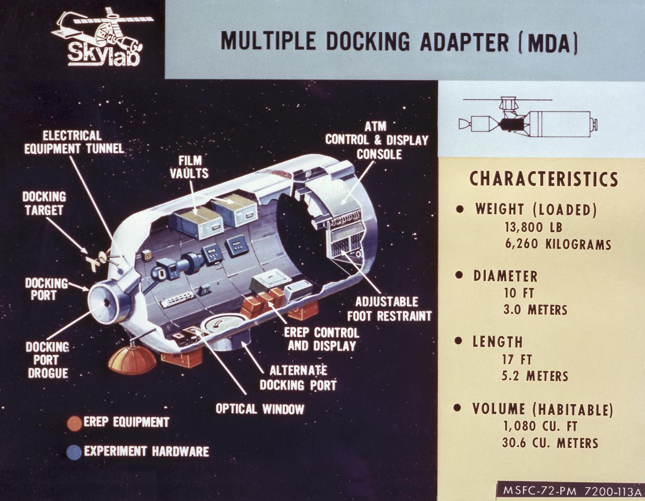
This cutaway drawing details the major characteristics of the Skylab Multiple Docking Adapter (MDA). The MDA, built under the direction of the Marshall Space Flight Center, housed the control units for the Apollo Telescope Mount (ATM), Earth Resources Experiment Package (EREP), and Zero-Gravity Materials Processing Facility, and provided a docking port for the Apollo Command Module (CM).
A new three-place North American O-47A observation airplane with Army Air Corps marking was the first ircraft to arrive at Ames. The Circular antenna on top of the canopy is for direction finding. A close look show that help from the front cockpit was needed for directional control when using a rope (instead of a tow bar) to tow the aircraft. (Sept 1940). W.H. McAvoy Ames test pilot returning from an early flight of first test airplane at Ames, a North American O-47A-1 (or 0-47 AAC37-323) This aircraft severed for a short time upon arrival as a research aircraft for heated-wing deicing. NOTE: printed in NASA Ames Publications: Adventures in Research - SP-4320 57 Years - Flight Research at AMES - NASA SP-1998-3300
The primary objective of the STS-35 mission was round the clock observation of the celestial sphere in ultraviolet and X-Ray astronomy with the Astro-1 observatory which consisted of four telescopes: the Hopkins Ultraviolet Telescope (HUT); the Wisconsin Ultraviolet Photo-Polarimeter Experiment (WUPPE); the Ultraviolet Imaging Telescope (UIT); and the Broad Band X-Ray Telescope (BBXRT). The Huntsville Operations Support Center (HOSC) Spacelab Payload Operations Control Center (SL POCC) at the Marshall Space Flight Center (MSFC) was the air/ground communication channel used between the astronauts and ground control teams during the Spacelab missions. Teams of controllers and researchers directed on-orbit science operations, sent commands to the spacecraft, received data from experiments aboard the Space Shuttle, adjusted mission schedules to take advantage of unexpected science opportunities or unexpected results, and worked with crew members to resolve problems with their experiments. Pictured is Jack Jones in the Mission Manager Area.
The primary objective of the STS-35 mission was round the clock observation of the celestial sphere in ultraviolet and X-Ray astronomy with the Astro-1 observatory which consisted of four telescopes: the Hopkins Ultraviolet Telescope (HUT); the Wisconsin Ultraviolet Photo-Polarimeter Experiment (WUPPE); the Ultraviolet Imaging Telescope (UIT); and the Broad Band X-Ray Telescope (BBXRT). The Huntsville Operations Support Center (HOSC) Spacelab Payload Operations Control Center (SL POCC) at the Marshall Space Flight Center (MSFC) was the air/ground communication channel used between the astronauts and ground control teams during the Spacelab missions. Teams of controllers and researchers directed on-orbit science operations, sent commands to the spacecraft, received data from experiments aboard the Space Shuttle, adjusted mission schedules to take advantage of unexpected science opportunities or unexpected results, and worked with crew members to resolve problems with their experiments. Pictured is the TV OPS area of the SL POCC.

KENNEDY SPACE CENTER, FLA. - In the Launch Control Center, Robert Holl (left), Landing Recovery directo, and Donald Hammel, from the Shuttle Project Office, are in contact with the leaders of the “Mode VII” emergency landing simulation at Kennedy Space Center. The simulation is being managed and directed from the LCC. The purpose of the Mode VII is to exercise emergency preparedness personnel, equipment and facilities in rescuing astronauts from a downed orbiter and providing immediate medical attention. This simulation presents an orbiter that has crashed short of the Shuttle Landing Facility in a wooded area 2-1/2 miles south of Runway 33. Emergency crews are responding to the volunteer “astronauts” who are simulating various injuries inside the crew compartment mock-up. Rescuers must remove the crew, provide triage and transport to hospitals those who need further treatment. Local hospitals are participating in the exercise.
KENNEDY SPACE CENTER, FLA. - In the Launch Control Center, officials monitor the “Mode VII” emergency landing simulation being conducted at Kennedy Space Center and managed and directed from the LCC. From left are Dr. Luis Moreno and Dr. David Reed, with Bionetics Life Sciences, and Dr. Philip Scarpa, with the KSC Safety, Occupational Health and Environment Division. The purpose of the Mode VII is to exercise emergency preparedness personnel, equipment and facilities in rescuing astronauts from a downed orbiter and providing immediate medical attention. This simulation presents an orbiter that has crashed short of the Shuttle Landing Facility in a wooded area 2-1/2 miles south of Runway 33. Emergency crews are responding to the volunteer “astronauts” who are simulating various injuries inside the crew compartment mock-up. Rescuers must remove the crew, provide triage and transport to hospitals those who need further treatment. Local hospitals are participating in the exercise.
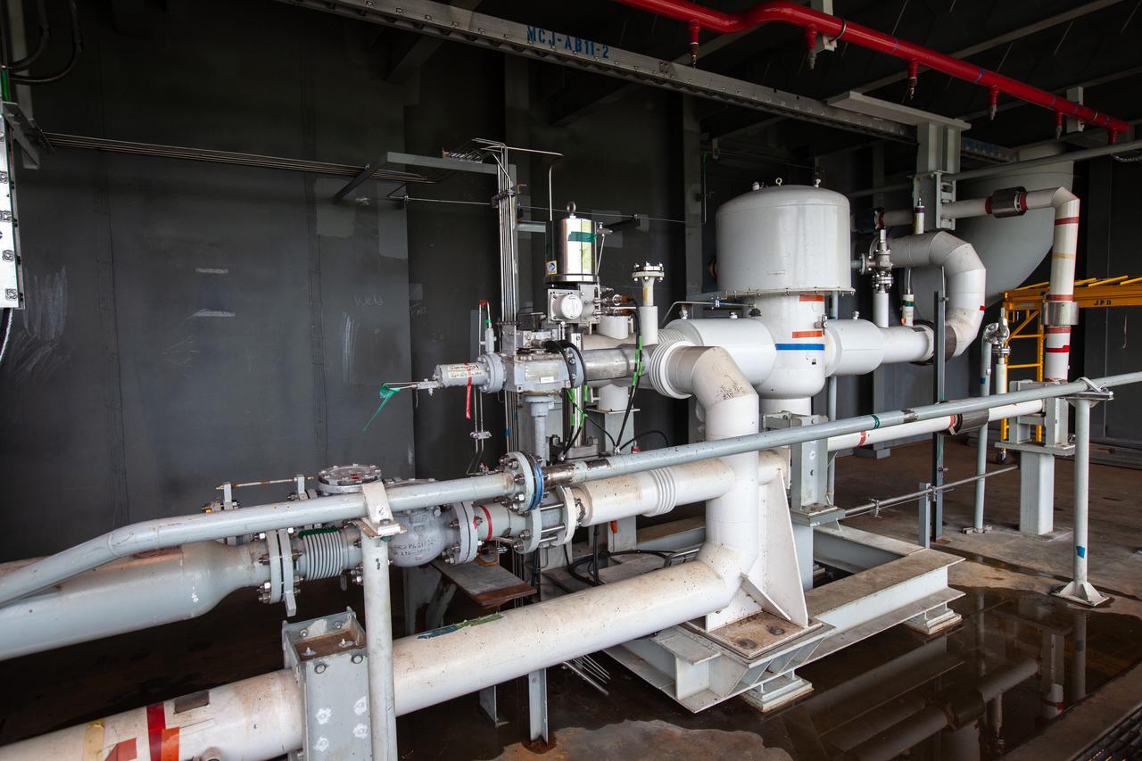
The control panel that will direct and control the flow of liquid oxygen, referred to as a skid, is photographed at Launch Pad 39B on Nov. 8, 2019, at NASA’s Kennedy Space Center in Florida. The agency’s Exploration Ground Systems oversaw testing of the pad’s cryogenic systems – the infrastructure that will support the flow of liquid hydrogen and liquid oxygen from the storage tanks, located near the pad, to the Space Launch System (SLS) rocket – in preparation for the launch of SLS with the Orion spacecraft atop for the uncrewed Artemis I mission. Each of the liquid oxygen and liquid hydrogen tanks can hold more than 800,000 gallons of propellant. The liquid oxygen will require the use of pumps to push it from the tank to the rocket, while the lighter liquid hydrogen will make its way up to the pad using gaseous hydrogen to pressurize the sphere.
ISS035-E-030779 (25 April 2013) --- R 2, the dexterous humanoid robot that was carried up to the station by one of NASA's final shuttle flights in 2011, awaits a direction from NASA astronaut Tom Marshburn (seen in the robot's visor), Expedition 35 Flight Engineer, who was performing the second of a two-day session of Taskboard and Tele-operations with R 2 onboard the International Space Station. The goals for these activities were orientation and depth familiarization, individual hand grasp and hand-to-hand object transfer; and all were completed nominally. The Robonaut Tele-operation System is used to demonstrate the ability to effectively control Robonaut from the station. The research objective is to evaluate this control method in terms of its ability to perform tasks as well as measure the time necessary to complete the defined tasks. This capability will need to be developed to support future operations of Robonaut in the space environment as well as certain intravehicular activity situations.
The control panel that will direct and control the flow of liquid oxygen, referred to as a skid, is photographed at Launch Pad 39B on Nov. 8, 2019, at NASA’s Kennedy Space Center in Florida. The agency’s Exploration Ground Systems oversaw testing of the pad’s cryogenic systems – the infrastructure that will support the flow of liquid hydrogen and liquid oxygen from the storage tanks, located near the pad, to the Space Launch System (SLS) rocket – in preparation for the launch of SLS with the Orion spacecraft atop for the uncrewed Artemis I mission. Each of the liquid oxygen and liquid hydrogen tanks can hold more than 800,000 gallons of propellant. The liquid oxygen will require the use of pumps to push it from the tank to the rocket, while the lighter liquid hydrogen will make its way up to the pad using gaseous hydrogen to pressurize the sphere.
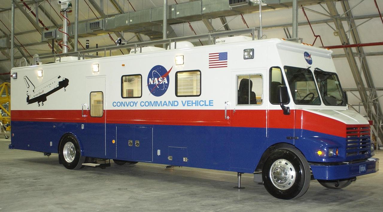
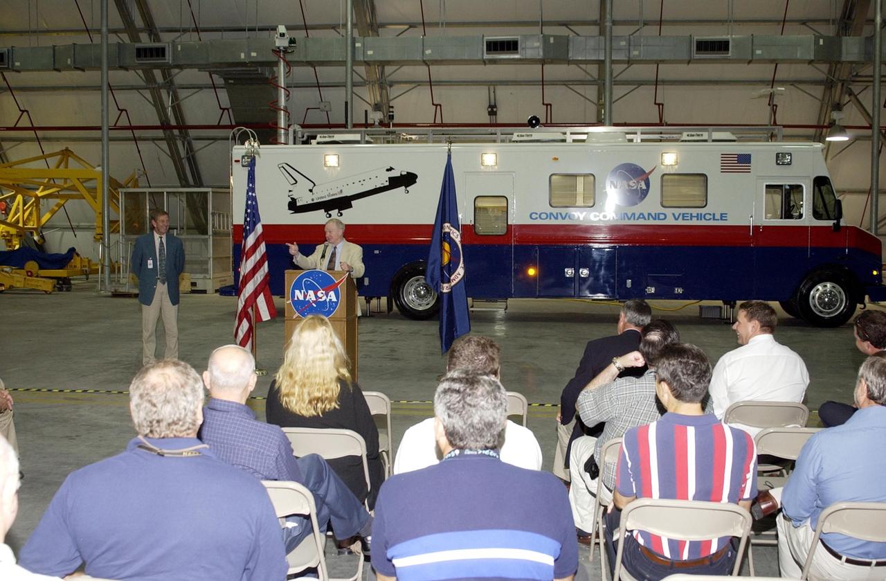
KENNEDY SPACE CENTER, FLA. -- The new Convoy Command Vehicle is displayed before a commissioning ceremony to hand it over to Center Director Roy Bridges Jr. The ceremony was to be held at the Landing Operations Facility. The new 40-foot vehicle is replacing a 15-year old model, and will be used following Shuttle landings as the prime vehicle to control critical communications between the orbiter, the crew and the Launch Control Center, to monitor the health of the Shuttle Orbiter systems and to direct convoy operations at the Shuttle Landing Facility. Upgrades and high-tech features incorporated into the design and development of this vehicle make it more reliable and efficient for the convoy crew. Seating capacity was increased from 4 to 12, and video recorders and television monitors were added to provide the convoy team with the maximum amount of visual information
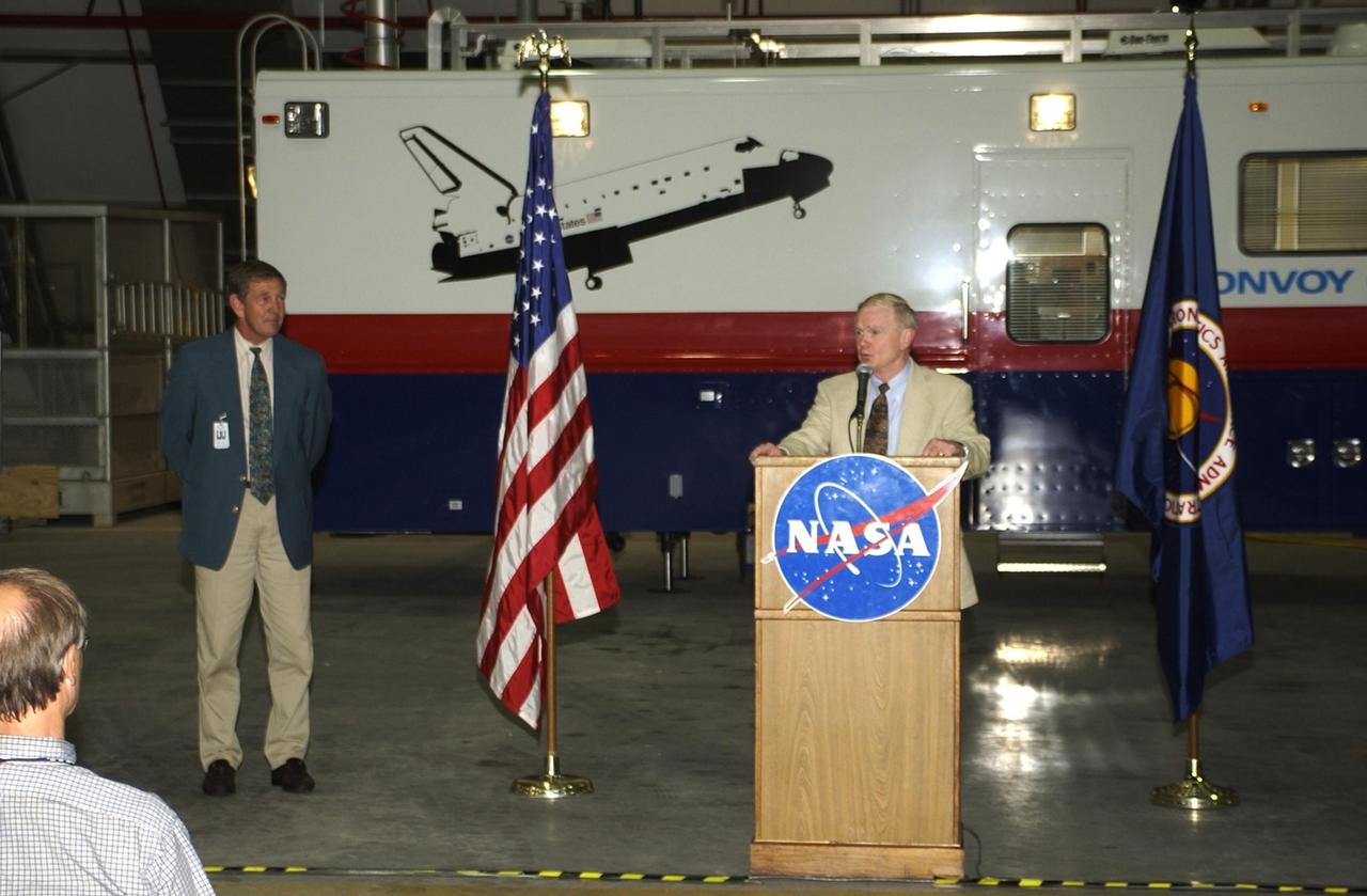
KENNEDY SPACE CENTER, FLA. -- At the podium, Center Director Roy Bridges Jr. offers remarks at the commissioning ceremony for the new Convoy Command Vehicle behind him. At left is Mike McCulley, chief operating officer, United Space Alliance. The new 40-foot vehicle is replacing a 15-year old model, and will be used following Shuttle landings as the prime vehicle to control critical communications between the orbiter, the crew and the Launch Control Center, to monitor the health of the Shuttle Orbiter systems and to direct convoy operations at the Shuttle Landing Facility. Upgrades and high-tech features incorporated into the design and development of this vehicle make it more reliable and efficient for the convoy crew. Seating capacity was increased from 4 to 12, and video recorders and television monitors were added to provide the convoy team with the maximum amount of visual information
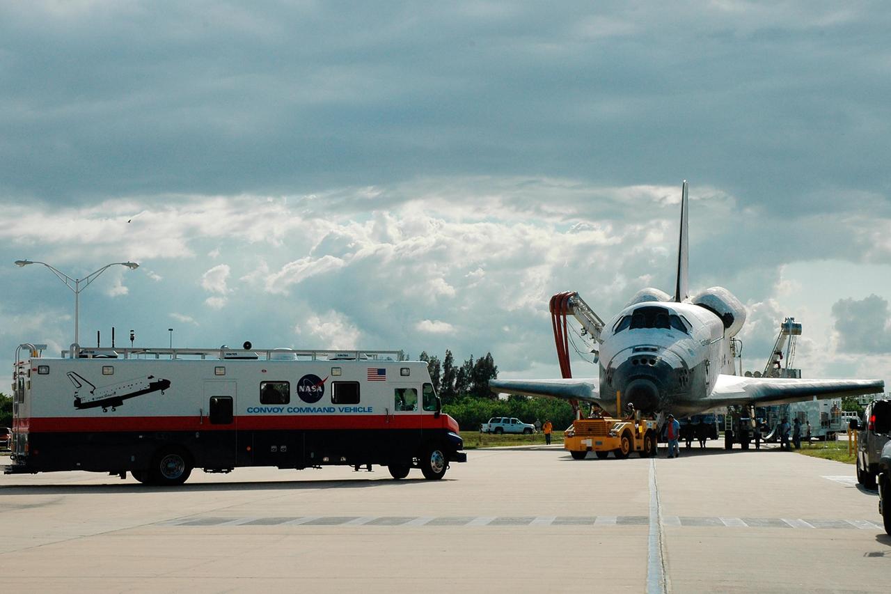
KENNEDY SPACE CENTER, FLA. -- The orbiter Endeavour is towed toward the Orbiter Processing Facility, known as the OPF. At left is the Convoy Command Vehicle. The mobile command center is the prime vehicle to control critical communications between the orbiter, the crew and the Launch Control Center after a shuttle landing to monitor the health of the shuttle orbiter systems and to direct convoy operations at the Shuttle Landing Facility. Endeavour returned to Earth Aug. 21 from mission STS-118, landing at Kennedy at 12:32 p.m. EDT. In the OPF bay 2, Endeavour will incur thermal protection system inspections and numerous other post-flight inspections before processing starts for its next voyage into space. Endeavour will next fly on mission STS-123 targeted for Feb. 14, 2008. Photo credit: NASA/Jack Pfaller
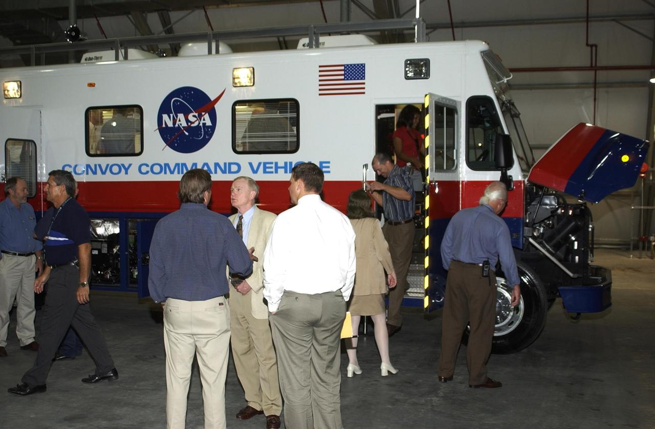
KENNEDY SPACE CENTER, FLA. -- While guests tour the new Convoy Command Vehicle (rear), Center Director Roy Bridges Jr. (center) talks to Launch Director Mike Leinbach. The tour followed a commissioning ceremony for the new vehicle. The 40-foot vehicle is replacing a 15-year old model, and will be used following Shuttle landings as the prime vehicle to control critical communications between the orbiter, the crew and the Launch Control Center, to monitor the health of the Shuttle Orbiter systems and to direct convoy operations at the Shuttle Landing Facility. Upgrades and high-tech features incorporated into the design and development of this vehicle make it more reliable and efficient for the convoy crew. Seating capacity was increased from 4 to 12, and video recorders and television monitors were added to provide the convoy team with the maximum amount of visual information
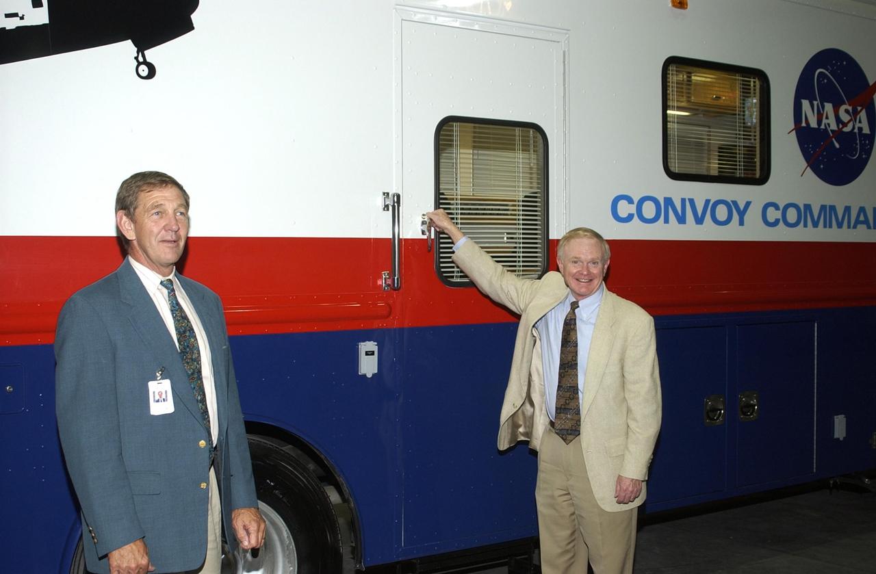
KENNEDY SPACE CENTER, FLA. - After opening remarks at a commissioning ceremony for the new Convoy Command Vehicle, Center Director Roy Bridges Jr. (right) gets ready to open the door for a tour of the vehicle. At left is United Space Alliance Chief Operating Officer Mike McCulley. The new 40-foot vehicle is replacing a 15-year old model, and will be used following Shuttle landings as the prime vehicle to control critical communications between the orbiter, the crew and the Launch Control Center, to monitor the health of the Shuttle Orbiter systems and to direct convoy operations at the Shuttle Landing Facility. Upgrades and high-tech features incorporated into the design and development of this vehicle make it more reliable and efficient for the convoy crew. Seating capacity was increased from 4 to 12, and video recorders and television monitors were added to provide the convoy team with the maximum amount of visual information
The control panel that will direct and control the flow of liquid oxygen and liquid oxygen, referred to as a skid, is photographed at Launch Pad 39B on Nov. 8, 2019, at NASA’s Kennedy Space Center in Florida. The agency’s Exploration Ground Systems oversaw testing of the pad’s cryogenic systems – the infrastructure that will send the liquid hydrogen and liquid oxygen from the storage tanks to the Space Launch System (SLS) rocket – in preparation for the launch of SLS with the Orion spacecraft atop for the uncrewed Artemis I mission. Each of the liquid oxygen and liquid hydrogen tanks can hold more than 800,000 gallons of propellant. The liquid oxygen will require the use of pumps to push it from the tank to the rocket, while the lighter liquid hydrogen will make its way up to the pad using gaseous hydrogen to pressurize the sphere.
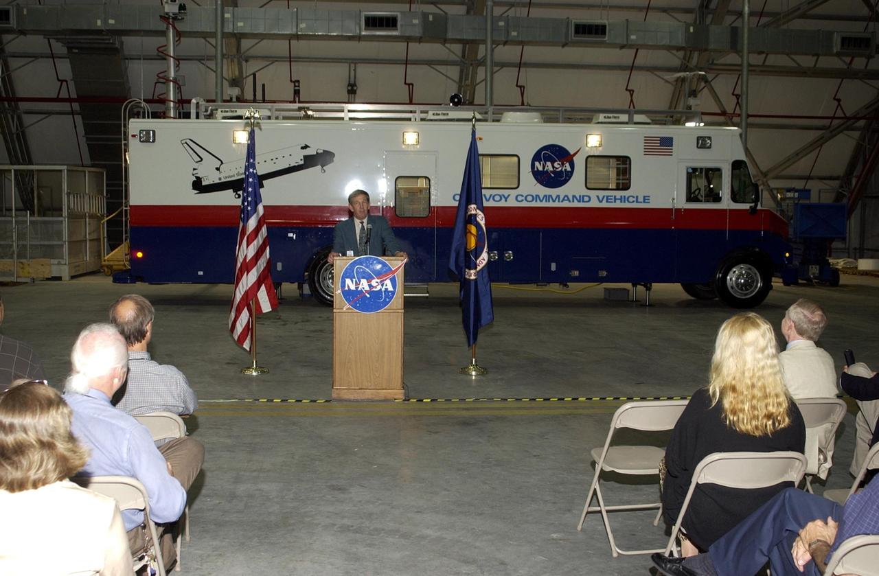
KENNEDY SPACE CENTER, FLA. -- United Space Alliance Chief Operating Officer Mike McCulley welcomes guests to the Landing Operations Facility and commissioning ceremony for the new Convoy Command Vehicle behind him. The new 40-foot vehicle is replacing a 15-year old model, and will be used following Shuttle landings as the prime vehicle to control critical communications between the orbiter, the crew and the Launch Control Center, to monitor the health of the Shuttle Orbiter systems and to direct convoy operations at the Shuttle Landing Facility. Upgrades and high-tech features incorporated into the design and development of this vehicle make it more reliable and efficient for the convoy crew. Seating capacity was increased from 4 to 12, and video recorders and television monitors were added to provide the convoy team with the maximum amount of visual information
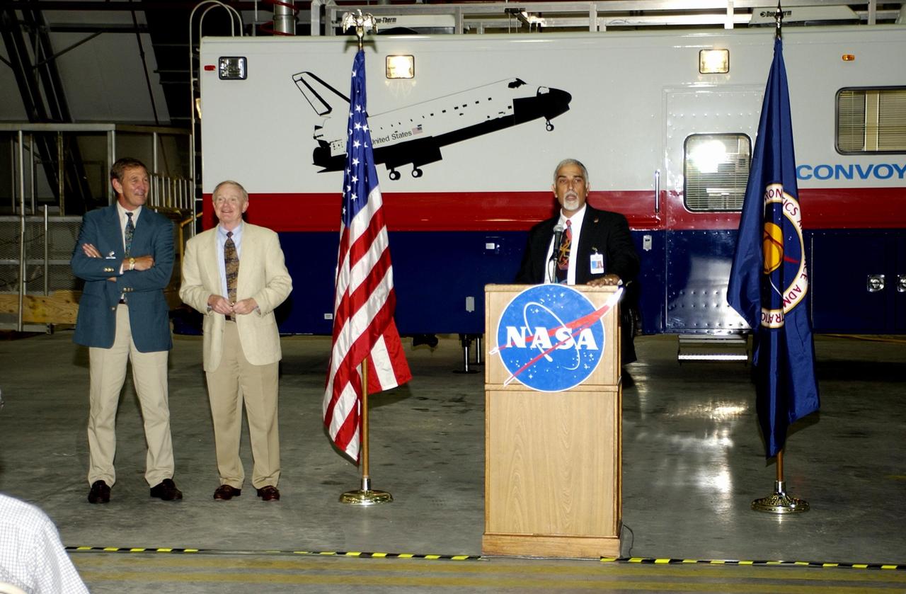
KENNEDY SPACE CENTER, FLA. -- During a commissioning ceremony for the new Convoy Command Vehicle (background), Tony Shibly, project manager, United Space Alliance, offers a few remarks to guests. At left are USA Chief Operating Officer Mike McCulley and Center Director Roy Bridges Jr. The new 40-foot vehicle is replacing a 15-year old model, and will be used following Shuttle landings as the prime vehicle to control critical communications between the orbiter, the crew and the Launch Control Center, to monitor the health of the Shuttle Orbiter systems and to direct convoy operations at the Shuttle Landing Facility. Upgrades and high-tech features incorporated into the design and development of this vehicle make it more reliable and efficient for the convoy crew. Seating capacity was increased from 4 to 12, and video recorders and television monitors were added to provide the convoy team with the maximum amount of visual information
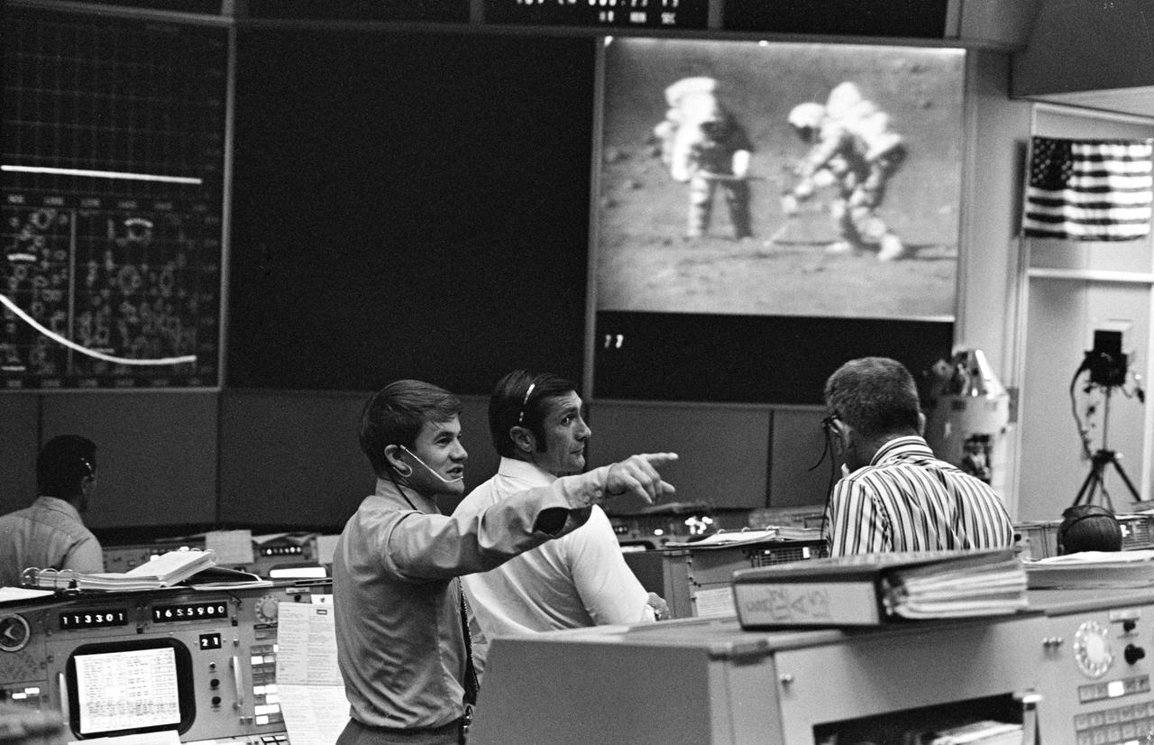
S71-41836 (2 Aug. 1971) --- Scientist-astronaut Joseph P. Allen, left, directs the attention of astronaut Richard F. Gordon Jr., to an occurrence out of view at right in the Mission Control Center's (MCC) Mission Operations Control Room (MOCR), while Dr. Donald K. (Deke) Slayton, on right with back to camera, views activity of Apollo 15 on a large screen at the front of the MOCR. Astronauts David R. Scott and James B. Irwin are seen on the screen performing tasks of the mission's third extravehicular activity (EVA), on Aug. 2, 1971. Dr. Slayton is director of Flight Crew Operations, NASA-MSC; Gordon is Apollo 15 backup commander; and Dr. Allen is an Apollo 15 spacecraft communicator.
KENNEDY SPACE CENTER, FLA. -- At the podium, Center Director Roy Bridges Jr. offers remarks at the commissioning ceremony for the new Convoy Command Vehicle behind him. At left is Mike McCulley, chief operating officer, United Space Alliance. The new 40-foot vehicle is replacing a 15-year old model, and will be used following Shuttle landings as the prime vehicle to control critical communications between the orbiter, the crew and the Launch Control Center, to monitor the health of the Shuttle Orbiter systems and to direct convoy operations at the Shuttle Landing Facility. Upgrades and high-tech features incorporated into the design and development of this vehicle make it more reliable and efficient for the convoy crew. Seating capacity was increased from 4 to 12, and video recorders and television monitors were added to provide the convoy team with the maximum amount of visual information
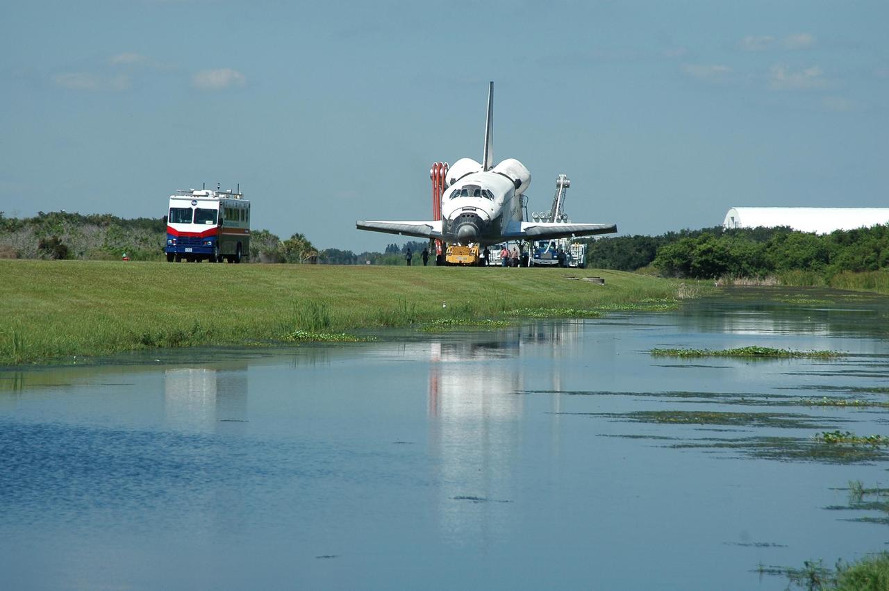
KENNEDY SPACE CENTER, FLA. - Led by the Convoy Command Center, Atlantis is towed from the Shuttle Landing Facility to the Orbiter Processing Facility. The command center is the prime vehicle to control critical communications between the orbiter, the crew and the Launch Control Center after a shuttle landing, to monitor the health of the shuttle orbiter systems and to direct convoy operations at the Shuttle Landing Facility. Atlantis landed on Runway 33 at 6:21:30 a.m. EDT after the 11-day, 19-hour, 6-minute mission STS-115 to the International Space Station. Atlantis traveled 4.9 million miles, landing on orbit 187. During the mission, astronauts delivered and installed the massive P3/P4 truss, an integral part of the station's backbone, and two sets of solar arrays that will eventually provide one quarter of the station's power. In the OPF, the process flow will begin to ready the vehicle for its next flight. Photo credit: NASA/Kim Shiflett

True-color (left) and false-color (right) mosaics of Jupiter's northern hemisphere between 10 and 50 degrees latitude. Jupiter's atmospheric motions are controlled by alternating eastward and westward bands of air between Jupiter's equator and polar regions. The direction and speed of these bands influences the color and texture of the clouds seen in this mosaic. The high and thin clouds are represented by light blue, deep clouds are reddish, and high and thick clouds are white. A high haze overlying a clear, deep atmosphere is represented by dark purple. This image was taken by NASA's Galileo spacecraft on April 3, 1997 at a distance of 1.4 million kilometers (.86 million miles). http://photojournal.jpl.nasa.gov/catalog/PIA03000
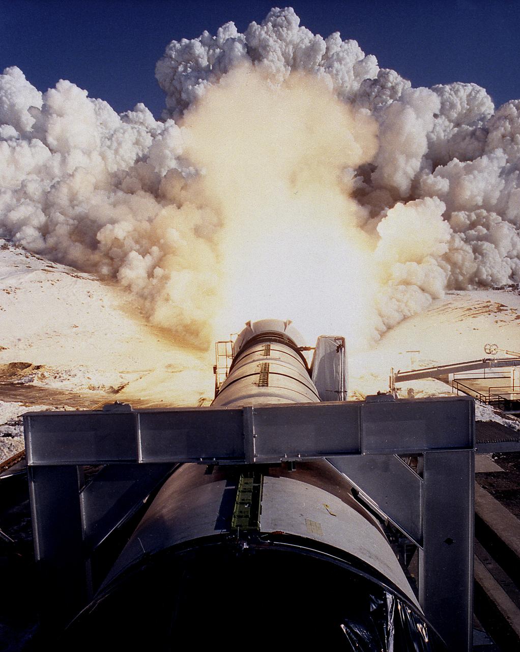
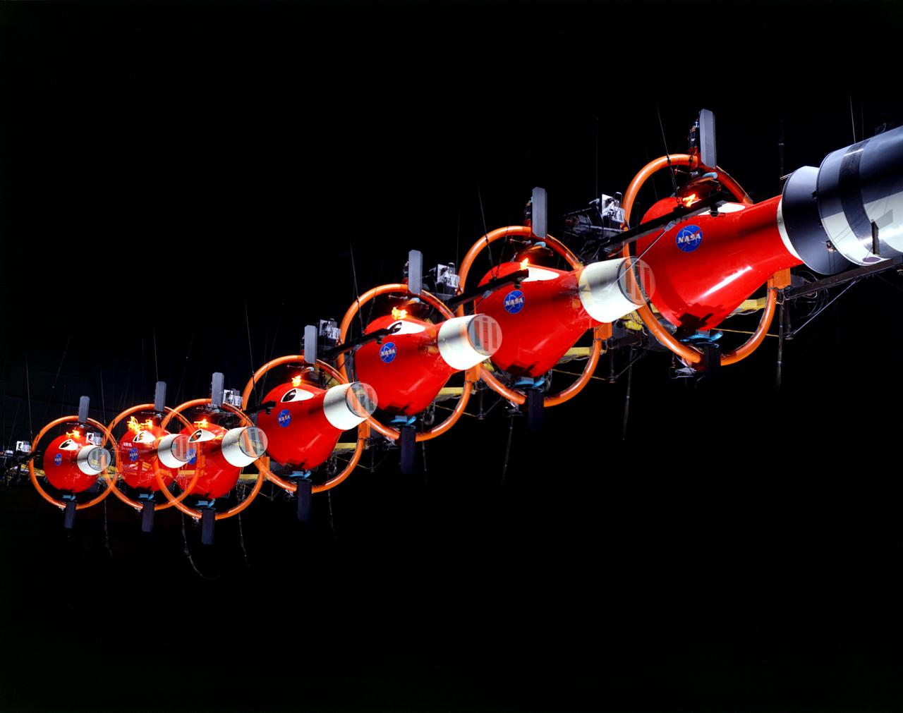
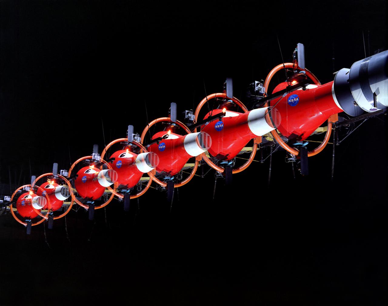
This photograph shows a static firing test of the Solid Rocket Qualification Motor-8 (QM-8) at the Morton Thiokol Test Site in Wasatch, Utah. The twin solid rocket boosters provide the majority of thrust for the first two minutes of flight, about 5.8 million pounds, augmenting the Shuttle's main propulsion system during liftoff. The major design drivers for the solid rocket motors (SRM's) were high thrust and reuse. The desired thrust was achieved by using state-of-the-art solid propellant and by using a long cylindrical motor with a specific core design that allows the propellant to burn in a carefully controlled marner. Under the direction of the Marshall Space Flight Center, the SRM's are provided by the Morton Thiokol Corporation.
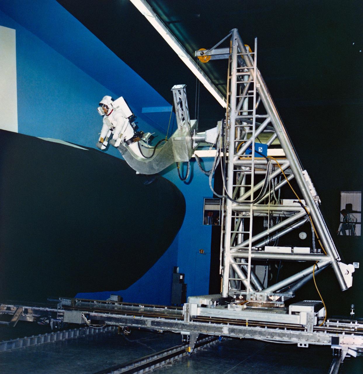
S80-36889 (24 July 1980) --- Astronaut Bruce McCandless II uses a simulator at Martin Marietta?s space center near Denver to develop flight techniques for a backpack propulsion unit that will be used on Space Shuttle flights. The manned maneuvering unit (MMU) training simulator allows astronauts to "fly missions" against a full scale mockup of a portion of the orbiter vehicle. Controls of the simulator are like those of the actual MMU. Manipulating them allows the astronaut to move in three straight-line directions and in pitch, yaw and roll. One possible application of the MMU is for an extravehicular activity chore to repair damaged tiles on the vehicle. McCandless is wearing an extravehicular mobility unit (EMU).
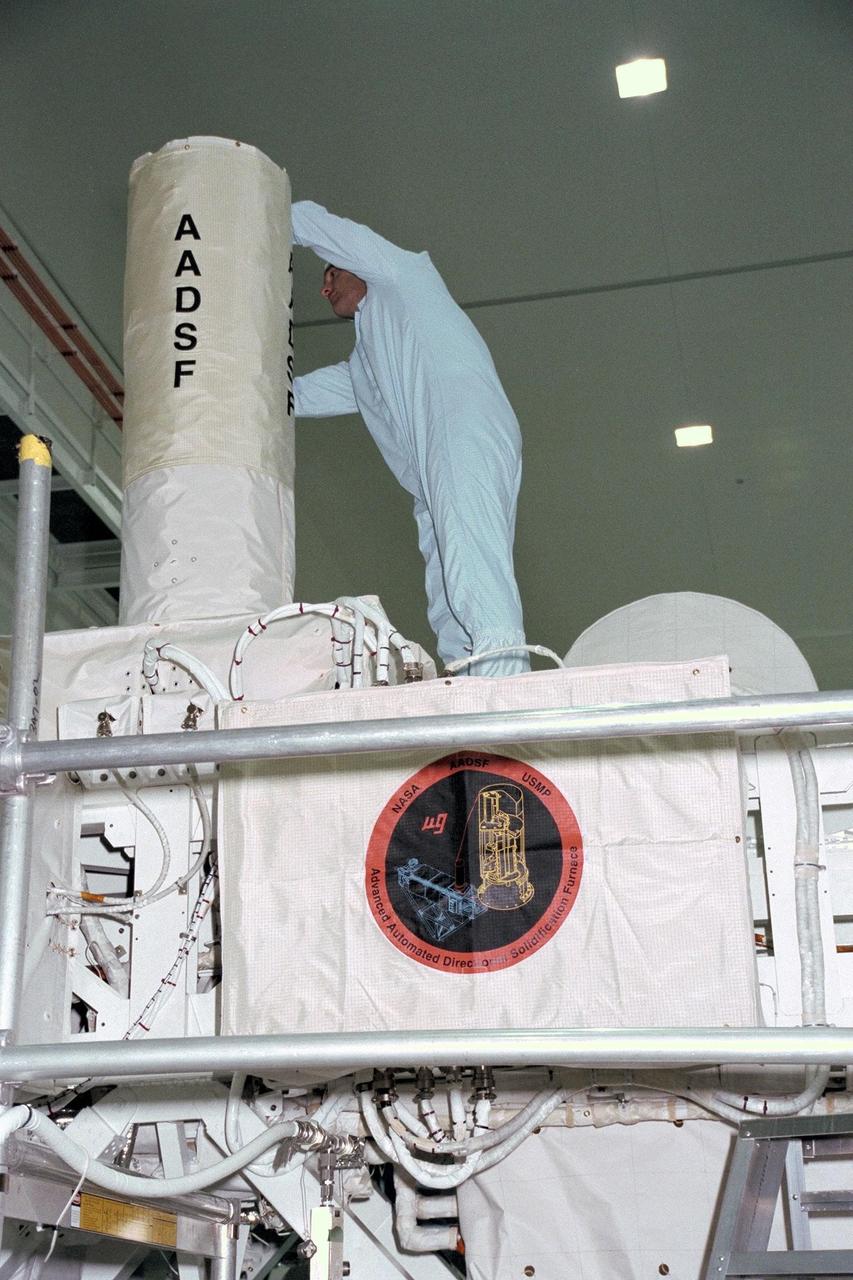
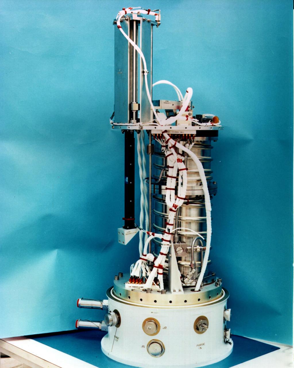
United States Microgravity Payload-4 (USMP-4) experiments are prepared to be flown on Space Shuttle mission STS-87 in the Space Station Processing Facility at Kennedy Space Center (KSC). A technician is working on the Advanced Automated Directional Solidification Furnace (AADSF), which will be used by researchers to study the solidification of semiconductor materials in microgravity. Scientists will be able to better understand how microgravity influences the solidification process of these materials and develop better methods for controlling that process during future Space flights and Earth-based production. All STS-87 experiments are scheduled for launch on Nov. 19 from KSC
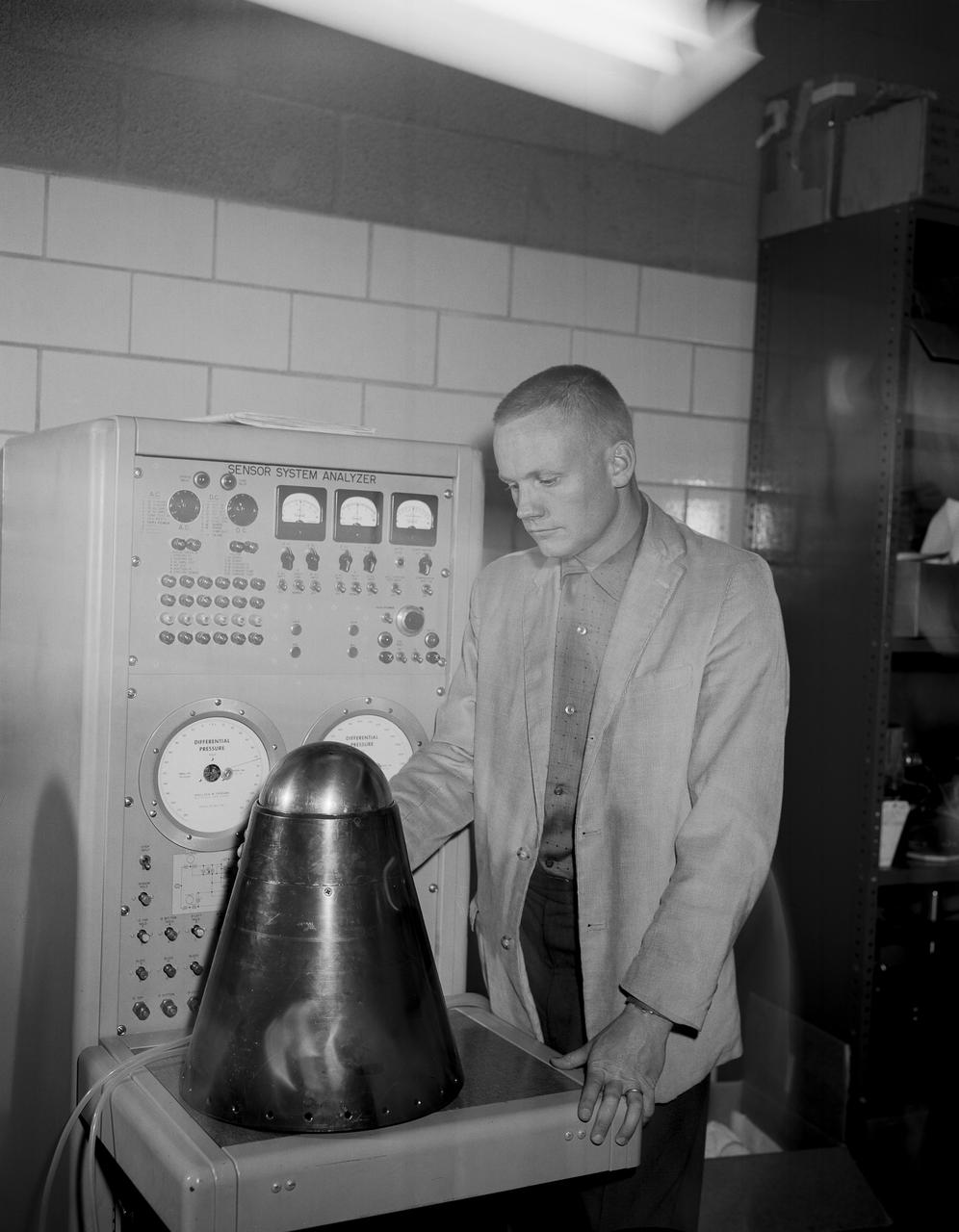
From the program’s inception, Neil Armstrong was actively engaged in both the piloting and engineering aspects of the X-15. He flew the first mission using a new flow-direction sensor (ball nose) and the first flight with a self-adaptive flight control system. Collaborating closely with designers and engineers on the system’s development, he made seven flights in the X-15 between December 1960 and July 1962. During these missions, he reached a peak altitude of 207,500 feet in the X-15-3 and a top speed of 3,989 mph (Mach 5.74) in the X-15-1.
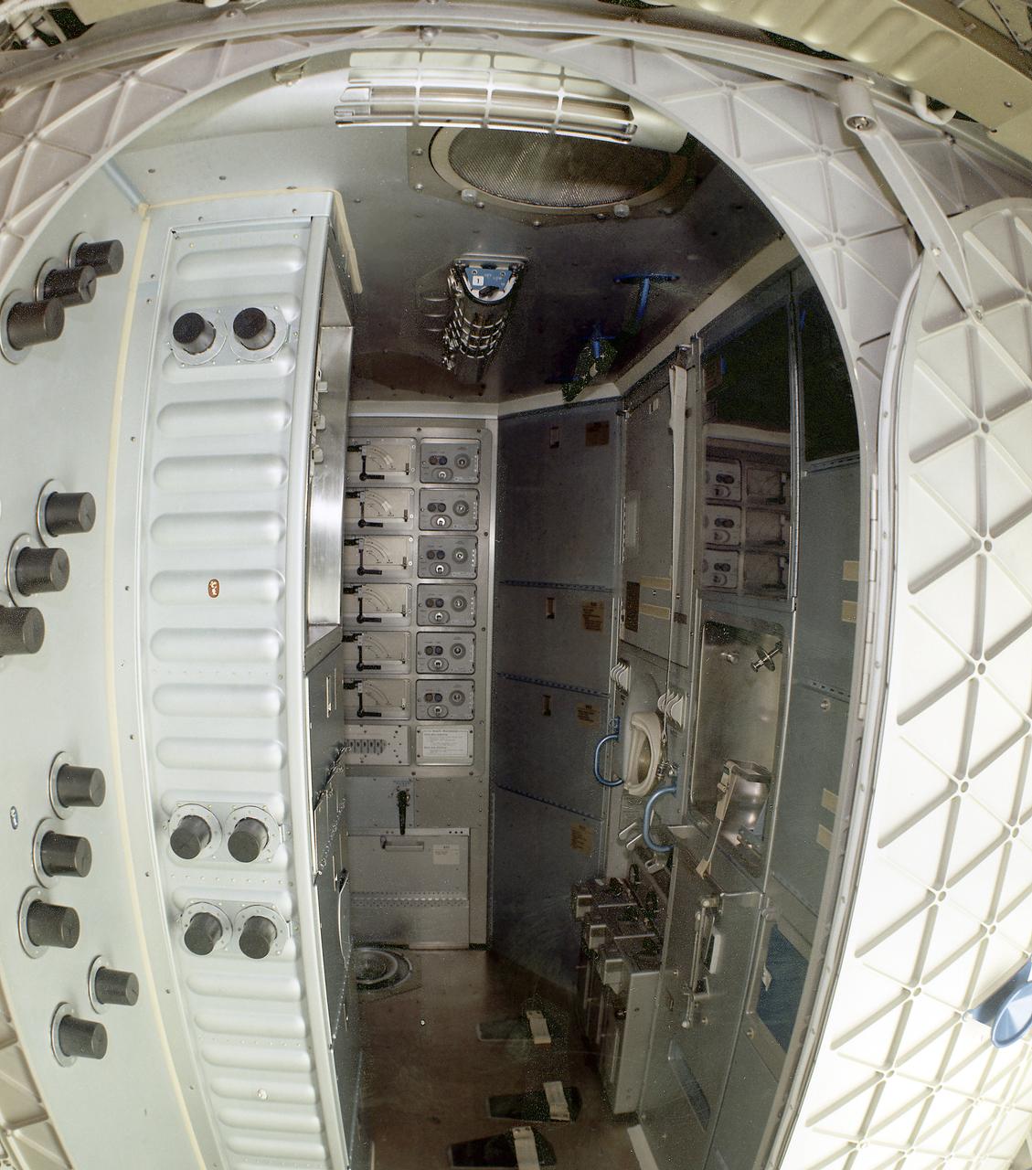
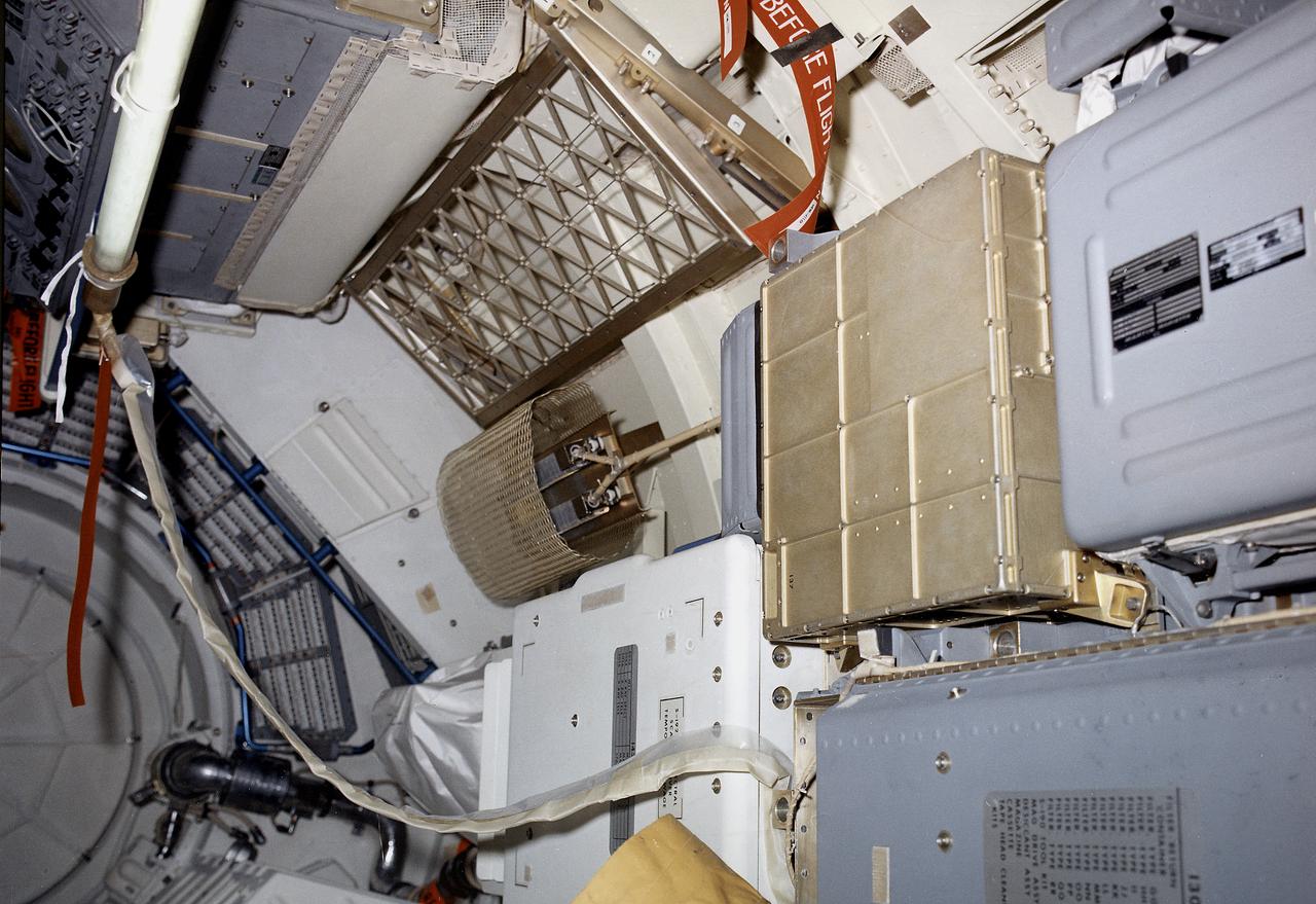
This image is a wide-angle view of the Orbital Workshop waste management compartment. The waste management facilities presented a unique challenge to spacecraft designers. In addition to collection of liquid and solid human wastes, there was a medical requirement to dry all solid human waste products and to return the residue to Earth for examination. Liquid human waste (urine) was frozen for return to Earth. Total quantities of each astronaut's liquid and solid wastes were precisely measured. Cabin air was drawn into the toilet, shown on the wall at right in this photograph, and over the waste products to generate a flow of the waste in the desired direction. The air was then filtered for odor control and antiseptic purposes prior to being discharged back into the cabin.
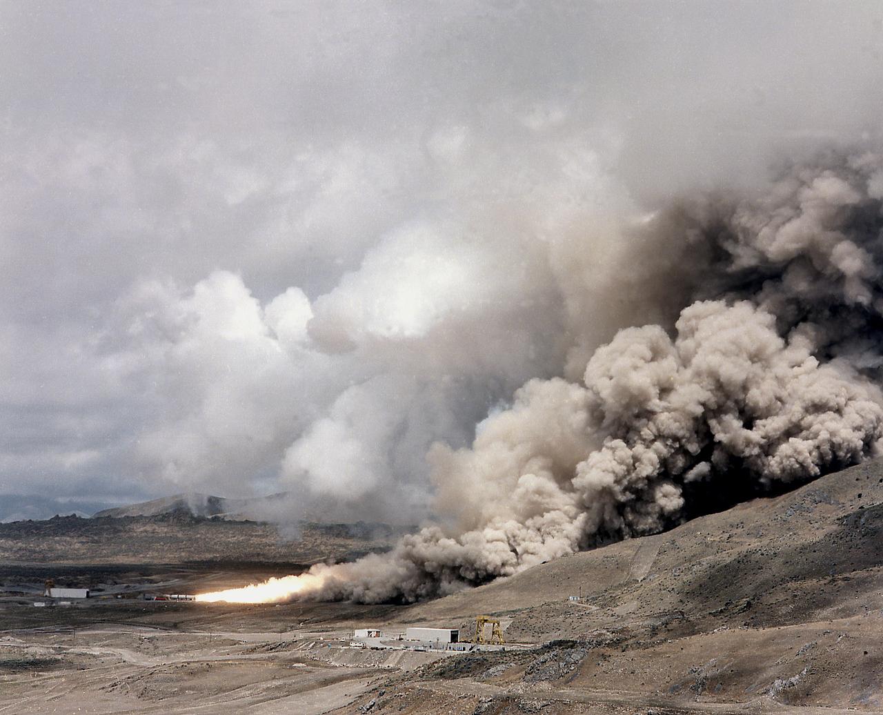
This photograph is a long shot view of a full scale solid rocket motor (SRM) for the solid rocket booster (SRB) being test fired at Morton Thiokol's Wasatch Operations in Utah. The twin boosters provide the majority of thrust for the first two minutes of flight, about 5.8 million pounds, augmenting the Shuttle's main propulsion system during liftoff. The major design drivers for the SRM's were high thrust and reuse. The desired thrust was achieved by using state-of-the-art solid propellant and by using a long cylindrical motor with a specific core design that allows the propellant to burn in a carefully controlled marner. Under the direction of the Marshall Space Flight Center, the SRM's are provided by the Morton Thiokol Corporation.
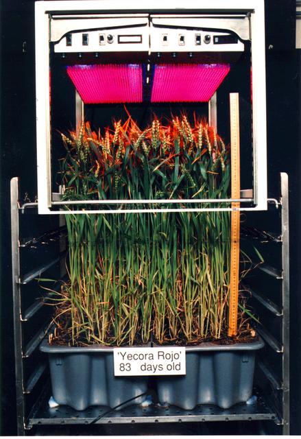
Astroculture is a suite of technologies used to produce and maintain a closed controlled environment for plant growth. The two most recent missions supported growth of potato, dwarf wheat, and mustard plants, and provided scientists with the first opportunity to conduct true plant research in space. Light emitting diodes have particular usefulness for plant growth lighting because they emit a much smaller amount of radiant heat than do conventional lighting sources and because they have potential of directing a higher percentage of the emitted light onto plants surfaces. Furthermore, the high output LED's have emissions in the 600-700 nm waveband, which is of highest efficiency for photosynthesis by plants.
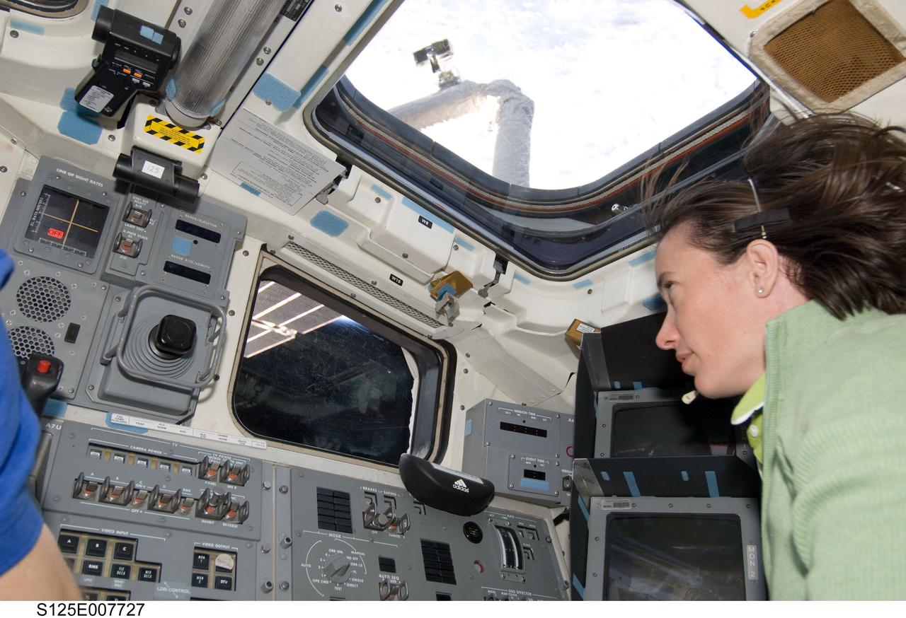
S125-E-007727 (15 May 2009) --- Astronaut Megan McArthur, STS-125 mission specialist, focuses on chores in support of the Atlantis' second session of extravehicular activity from the aft side of the crew cabin, where controls for the remote manipulator system arm, among other important elements, are located. Equipped with TV monitors and direct vision capabilities, via this vantage point she also can maintain visual contact with the two space walkers as they perform work on the Hubble Space Telescope, locked down in the shuttle's cargo bay.
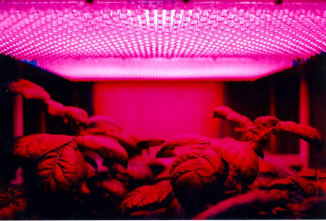
Astroculture is a suite of technologies used to produce and maintain a closed controlled environment for plant growth. The two most recent missions supported growth of potato, dwarf wheat, and mustard plants and provided scientists with the first opportunity to conduct true plant research in space. Light emitting diodes have particular usefulness for plant growth lighting because they emit a much smaller amount of radiant heat than do conventional lighting sources and because they have potential of directing a higher percentage of the emitted light onto plants surfaces. Furthermore, the high output LED's have emissions in the 600-700 nm waveband, which is of highest efficiency for photosynthesis by plants.
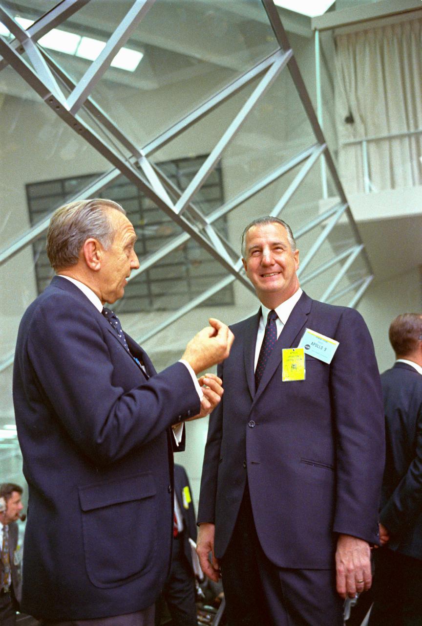
KENNEDY SPACE CENTER, FLA. -- Within the Launch Control Center, Vice President Spiro T. Agnew listens to Dr. Kurt H. Debus, director, Kennedy Space Center, explain highlights of the Apollo Program. The Vice President viewed the launch of Apollo 9 astronauts James A. McDivitt, David R. Scott and Russell L. Schweickart today. They were sent on a planned 10-day Earth orbital flight to put a lunar module spacecraft through extensive tests to qualify it for a possible manned lunar landing later this year. The National Aeronautics and Space Administration directs the Apollo Program.
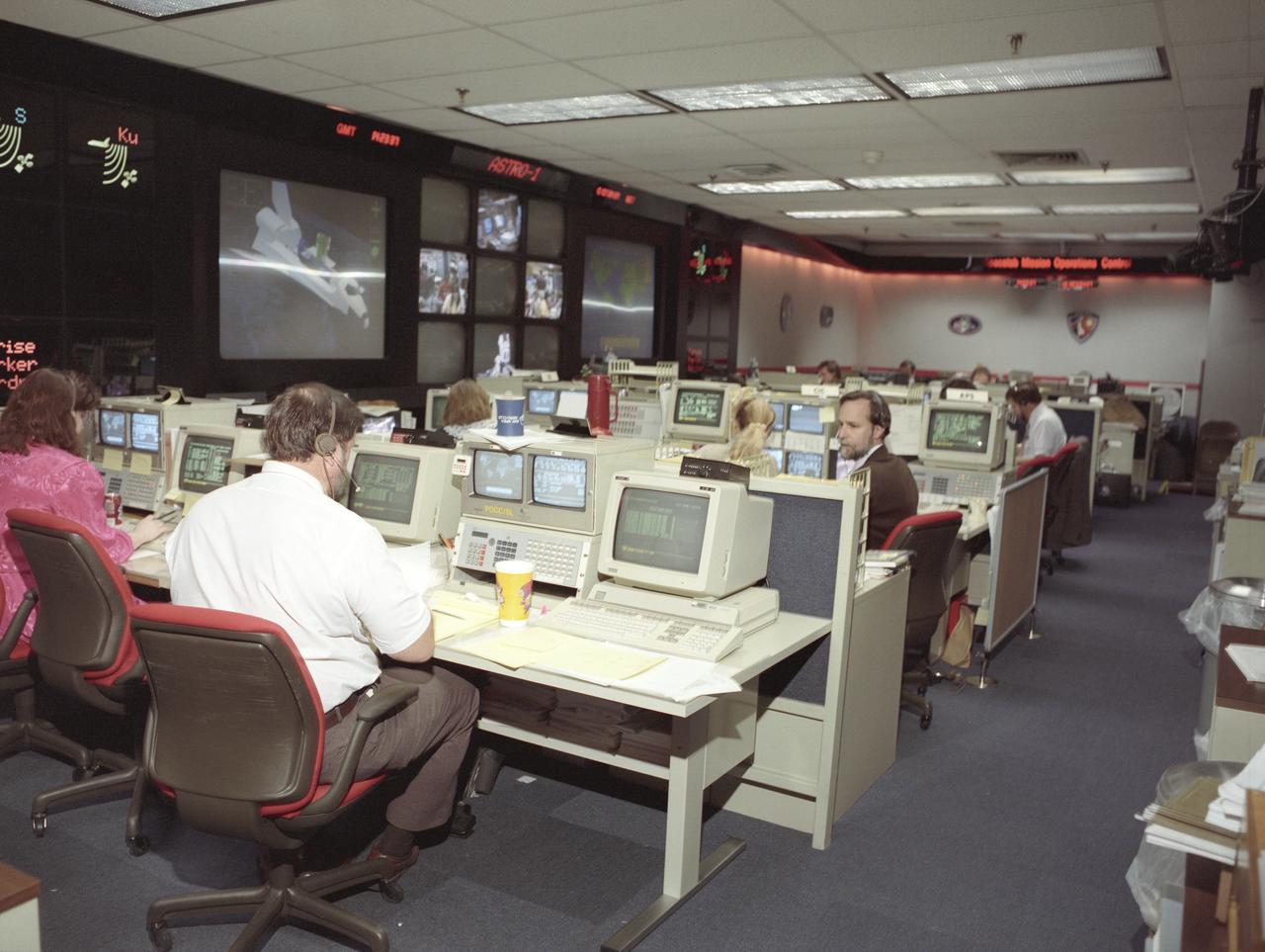
The primary objective of the STS-35 mission was round the clock observation of the celestial sphere in ultraviolet and X-Ray astronomy with the Astro-1 observatory which consisted of four telescopes: the Hopkins Ultraviolet Telescope (HUT); the Wisconsin Ultraviolet Photo-Polarimeter Experiment (WUPPE); the Ultraviolet Imaging Telescope (UIT); and the Broad Band X-Ray Telescope (BBXRT). The Huntsville Operations Support Center (HOSC) Spacelab Payload Operations Control Center (SL POCC) at the Marshall Space Flight Center (MSFC) was the air/ground communication channel used between the astronauts and ground control teams during the Spacelab missions. Teams of controllers and researchers directed on-orbit science operations, sent commands to the spacecraft, received data from experiments aboard the Space Shuttle, adjusted mission schedules to take advantage of unexpected science opportunities or unexpected results, and worked with crew members to resolve problems with their experiments. Due to loss of data used for pointing and operating the ultraviolet telescopes, MSFC ground teams were forced to aim the telescopes with fine tuning by the flight crew. This photo is an overview of the MSFC Payload Control Room (PCR).
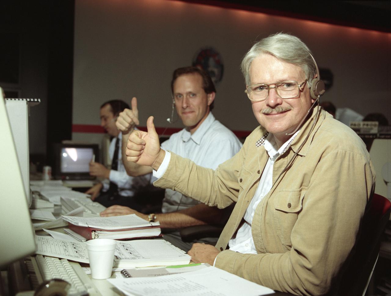
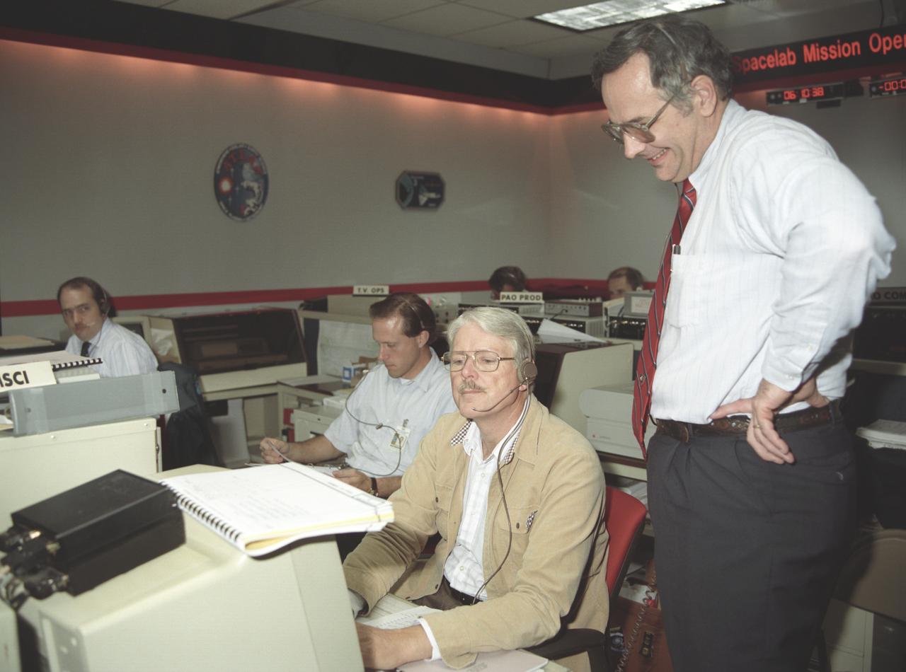
The primary objective of the STS-35 mission was round the clock observation of the celestial sphere in ultraviolet and X-Ray astronomy with the Astro-1 observatory which consisted of four telescopes: the Hopkins Ultraviolet Telescope (HUT); the Wisconsin Ultraviolet Photo-Polarimeter Experiment (WUPPE); the Ultraviolet Imaging Telescope (UIT); and the Broad Band X-Ray Telescope (BBXRT). The Huntsville Operations Support Center (HOSC) Spacelab Payload Operations Control Center (SL POCC) at the Marshall Space Flight Center (MSFC) was the air/ground communication channel used between the astronauts and ground control teams during the Spacelab missions. Teams of controllers and researchers directed on-orbit science operations, sent commands to the spacecraft, received data from experiments aboard the Space Shuttle, adjusted mission schedules to take advantage of unexpected science opportunities or unexpected results, and worked with crew members to resolve problems with their experiments. Due to loss of data used for pointing and operating the ultraviolet telescopes, MSFC ground teams were forced to aim the telescopes with fine tuning by the flight crew. This photo captures the activity at the Operations Control Facility during the mission as Dr. Urban and Paul Whitehouse give a “thumbs up”.
The primary objective of the STS-35 mission was round the clock observation of the celestial sphere in ultraviolet and X-Ray astronomy with the Astro-1 observatory which consisted of four telescopes: the Hopkins Ultraviolet Telescope (HUT); the Wisconsin Ultraviolet Photo-Polarimeter Experiment (WUPPE); the Ultraviolet Imaging Telescope (UIT); and the Broad Band X-Ray Telescope (BBXRT). The Huntsville Operations Support Center (HOSC) Spacelab Payload Operations Control Center (SL POCC) at the Marshall Space Flight Center (MSFC) was the air/ground communication channel used between the astronauts and ground control teams during the Spacelab missions. Teams of controllers and researchers directed on-orbit science operations, sent commands to the spacecraft, received data from experiments aboard the Space Shuttle, adjusted mission schedules to take advantage of unexpected science opportunities or unexpected results, and worked with crew members to resolve problems with their experiments. Due to loss of data used for pointing and operating the ultraviolet telescopes, MSFC ground teams were forced to aim the telescopes with fine tuning by the flight crew. Pictured onboard the shuttle is astronaut Robert Parker using a Manual Pointing Controller (MPC) for the ASTRO-1 mission Instrument Pointing System (IPS).
Multiple exposure of Rendezvous Docking Simulator. Francis B. Smith, described the simulator as follows: The rendezvous and docking operation of the Gemini spacecraft with the Agena and of the Apollo Command Module with the Lunar Excursion Module have been the subject of simulator studies for several years. This figure illustrates the Gemini-Agena rendezvous docking simulator at Langley. The Gemini spacecraft was supported in a gimbal system by an overhead crane and gantry arrangement which provided 6 degrees of freedom - roll, pitch, yaw, and translation in any direction - all controllable by the astronaut in the spacecraft. Here again the controls fed into a computer which in turn provided an input to the servos driving the spacecraft so that it responded to control motions in a manner which accurately simulated the Gemini spacecraft. -- Published in Barton C. Hacker and James M. Grimwood, On the Shoulders of Titans: A History of Project Gemini, NASA SP-4203 Francis B. Smith, Simulators for Manned Space Research, Paper presented at the 1966 IEEE International convention, March 21-25, 1966.
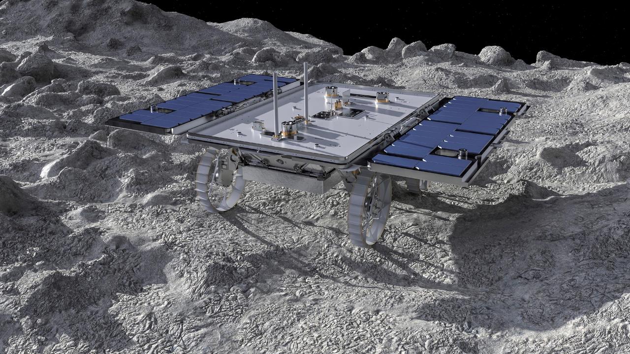
This artist's concept depicts a small rover – part of NASA's CADRE (Cooperative Autonomous Distributed Robotic Exploration) technology demonstration headed for the Moon – on the lunar surface. Motiv Space Systems in Pasadena, California, created the rendering and is collaborating with NASA's Jet Propulsion Laboratory on critical rover and mobility functions. Slated to arrive aboard a lunar lander in 2024 under NASA's CLPS (Commercial Lunar Payload Services) initiative, CADRE is designed to demonstrate that multiple robots can cooperate and explore together autonomously – without direct input from human mission controllers. A trio of the miniature solar-powered rovers, each about the size of a carry-on suitcase, will explore the Moon as a team, communicating via radio with each other and a base station aboard a lunar lander. By taking simultaneous measurements from multiple locations, CADRE will also demonstrate how multirobot missions can record data impossible for a single robot to achieve – a tantalizing prospect for future missions. Motiv contributed subsystems and hardware elements for three of four CADRE systems, including designing and building the mobility system and rover chassis, the base station, the rover deployers, and the motor controller boards. The company also procured and tested the actuators with the flight motor controller boards. https://photojournal.jpl.nasa.gov/catalog/PIA26161
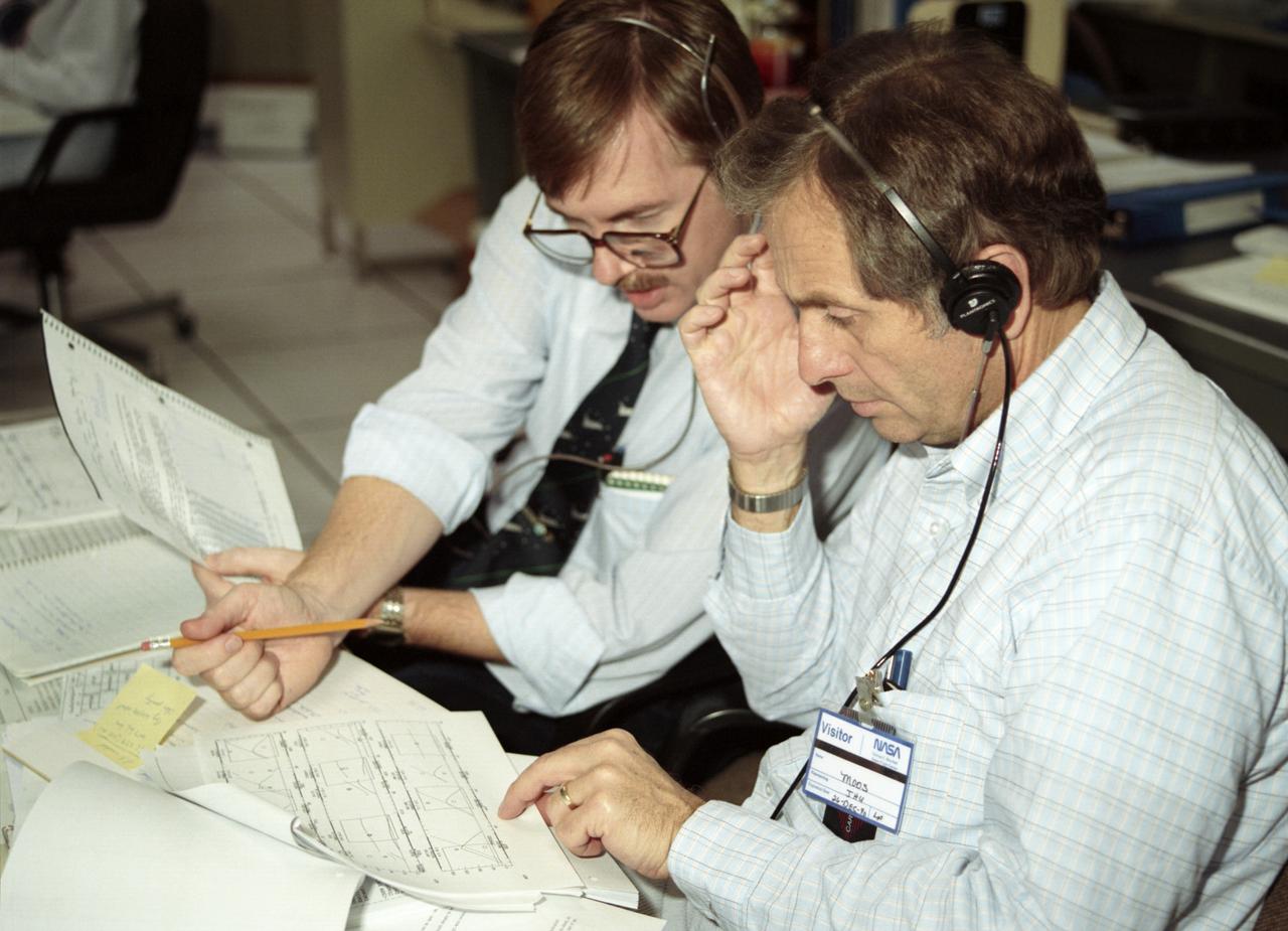
The primary objective of the STS-35 mission was round the clock observation of the celestial sphere in ultraviolet and X-Ray astronomy with the Astro-1 observatory which consisted of four telescopes: the Hopkins Ultraviolet Telescope (HUT); the Wisconsin Ultraviolet Photo-Polarimeter Experiment (WUPPE); the Ultraviolet Imaging Telescope (UIT); and the Broad Band X-Ray Telescope (BBXRT). The Huntsville Operations Support Center (HOSC) Spacelab Payload Operations Control Center (SL POCC) at the Marshall Space Flight Center (MSFC) was the air/ground communication channel used between the astronauts and ground control teams during the Spacelab missions. Teams of controllers and researchers directed on-orbit science operations, sent commands to the spacecraft, received data from experiments aboard the Space Shuttle, adjusted mission schedules to take advantage of unexpected science opportunities or unexpected results, and worked with crew members to resolve problems with their experiments. Due to loss of data used for pointing and operating the ultraviolet telescopes, MSFC ground teams were forced to aim the telescopes with fine tuning by the flight crew. This photo captures the activity of BBKRT data review in the Science Operations Area during the mission.
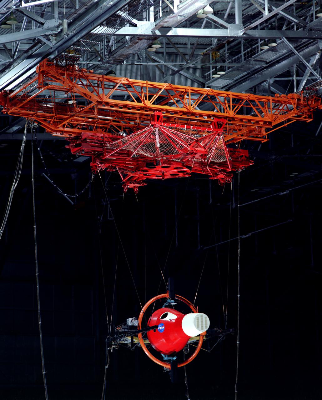
Gemini Rendezvous Docking Simulator suspended from the roof of the Langley Research Center s aircraft hangar. Francis B. Smith wrote: The rendezvous and docking operation of the Gemini spacecraft with the Agena and of the Apollo Command Module with the Lunar Excursion Module have been the subject of simulator studies for several years. This figure illustrates the Gemini-Agena rendezvous docking simulator at Langley. The Gemini spacecraft was supported in a gimbal system by an overhead crane and gantry arrangement which provided 6 degrees of freedom - roll, pitch, yaw, and translation in any direction - all controllable by the astronaut in the spacecraft. Here again the controls fed into a computer which in turn provided an input to the servos driving the spacecraft so that it responded to control motions in a manner which accurately simulated the Gemini spacecraft. -- Published in Barton C. Hacker and James M. Grimwood, On the Shoulders of Titans: A History of Project Gemini, NASA SP-4203 Francis B. Smith, Simulators for Manned Space Research, Paper presented at the 1966 IEEE International convention, March 21-25, 1966.
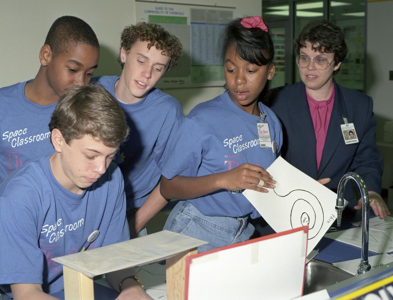
The primary objective of the STS-35 mission was round the clock observation of the celestial sphere in ultraviolet and X-Ray astronomy with the Astro-1 observatory which consisted of four telescopes: the Hopkins Ultraviolet Telescope (HUT); the Wisconsin Ultraviolet Photo-Polarimeter Experiment (WUPPE); the Ultraviolet Imaging Telescope (UIT); and the Broad Band X-Ray Telescope (BBXRT). The Huntsville Operations Support Center (HOSC) Spacelab Payload Operations Control Center (SL POCC) at the Marshall Space Flight Center (MSFC) was the air/ground communication channel used between the astronauts and ground control teams during the Spacelab missions. Teams of controllers and researchers directed on-orbit science operations, sent commands to the spacecraft, received data from experiments aboard the Space Shuttle, adjusted mission schedules to take advantage of unexpected science opportunities or unexpected results, and worked with crew members to resolve problems with their experiments. This photo is of Space classroom students in the Discovery Optics Lab at MSFC during STS-35, ASTRO-1 mission payload operations.
The primary objective of the STS-35 mission was round the clock observation of the celestial sphere in ultraviolet and X-Ray astronomy with the Astro-1 observatory which consisted of four telescopes: the Hopkins Ultraviolet Telescope (HUT); the Wisconsin Ultraviolet Photo-Polarimeter Experiment (WUPPE); the Ultraviolet Imaging Telescope (UIT); and the Broad Band X-Ray Telescope (BBXRT). The Huntsville Operations Support Center (HOSC) Spacelab Payload Operations Control Center (SL POCC) at the Marshall Space Flight Center (MSFC) was the air/ground communication channel used between the astronauts and ground control teams during the Spacelab missions. Teams of controllers and researchers directed on-orbit science operations, sent commands to the spacecraft, received data from experiments aboard the Space Shuttle, adjusted mission schedules to take advantage of unexpected science opportunities or unexpected results, and worked with crew members to resolve problems with their experiments. Due to loss of data used for pointing and operating the ultraviolet telescopes, MSFC ground teams were forced to aim the telescopes with fine tuning by the flight crew. This photo captures the activity of WUPPE data review at the Science Operations Area during the mission.
The primary objective of the STS-35 mission was round the clock observation of the celestial sphere in ultraviolet and X-Ray astronomy with the Astro-1 observatory which consisted of four telescopes: the Hopkins Ultraviolet Telescope (HUT); the Wisconsin Ultraviolet Photo-Polarimeter Experiment (WUPPE); the Ultraviolet Imaging Telescope (UIT); and the Broad Band X-Ray Telescope (BBXRT). The Huntsville Operations Support Center (HOSC) Spacelab Payload Operations Control Center (SL POCC) at the Marshall Space Flight Center (MSFC) was the air/ground communication channel used between the astronauts and ground control teams during the Spacelab missions. Teams of controllers and researchers directed on-orbit science operations, sent commands to the spacecraft, received data from experiments aboard the Space Shuttle, adjusted mission schedules to take advantage of unexpected science opportunities or unexpected results, and worked with crew members to resolve problems with their experiments. Due to loss of data used for pointing and operating the ultraviolet telescopes, MSFC ground teams were forced to aim the telescopes with fine tuning by the flight crew. This photo captures the activity of viewing HUT data in the Mission Manager Actions Room during the mission.
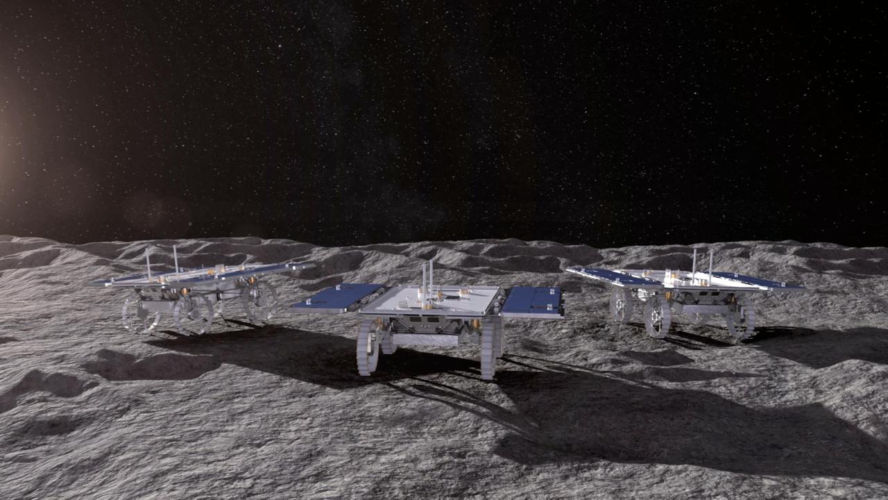
This animated artist's concept depicts three small rovers – part of NASA's CADRE (Cooperative Autonomous Distributed Robotic Exploration) technology demonstration headed for the Moon – driving together on the lunar surface. Motiv Space Systems in Pasadena, California, created the rendering and collaborated with NASA's Jet Propulsion Laboratory on critical rover and mobility functions. Slated to arrive aboard a lunar lander at the Reiner Gamma region of the Moon under NASA's CLPS (Commercial Lunar Payload Services) initiative, CADRE is designed to demonstrate that multiple robots can cooperate and explore together autonomously – without direct input from human mission controllers. A trio of the miniature solar-powered rovers, each about the size of a carry-on suitcase, will explore the Moon as a team, communicating via radio with each other and a base station aboard the lander. By taking simultaneous measurements from multiple locations, CADRE will also demonstrate how multirobot missions can record data impossible for a single robot to achieve – a tantalizing prospect for future missions. Motiv contributed subsystems and hardware elements for three of four CADRE systems, including designing and building the mobility system and rover chassis, the base station, the rover deployers, and the motor controller boards. The company also procured and tested the actuators with the flight motor controller boards. Animation available at https://photojournal.jpl.nasa.gov/catalog/PIA26296
The primary objective of the STS-35 mission was round the clock observation of the celestial sphere in ultraviolet and X-Ray astronomy with the Astro-1 observatory which consisted of four telescopes: the Hopkins Ultraviolet Telescope (HUT); the Wisconsin Ultraviolet Photo-Polarimeter Experiment (WUPPE); the Ultraviolet Imaging Telescope (UIT); and the Broad Band X-Ray Telescope (BBXRT). The Huntsville Operations Support Center (HOSC) Spacelab Payload Operations Control Center (SL POCC) at the Marshall Space Flight Center (MSFC) was the air/ground communication channel used between the astronauts and ground control teams during the Spacelab missions. Teams of controllers and researchers directed on-orbit science operations, sent commands to the spacecraft, received data from experiments aboard the Space Shuttle, adjusted mission schedules to take advantage of unexpected science opportunities or unexpected results, and worked with crew members to resolve problems with their experiments. Due to loss of data used for pointing and operating the ultraviolet telescopes, MSFC ground teams were forced to aim the telescopes with fine tuning by the flight crew. This photo captures a press briefing at MSFC during STS-35, ASTRO-1 Mission.
The primary objective of the STS-35 mission was round the clock observation of the celestial sphere in ultraviolet and X-Ray astronomy with the Astro-1 observatory which consisted of four telescopes: the Hopkins Ultraviolet Telescope (HUT); the Wisconsin Ultraviolet Photo-Polarimeter Experiment (WUPPE); the Ultraviolet Imaging Telescope (UIT); and the Broad Band X-Ray Telescope (BBXRT). The Huntsville Operations Support Center (HOSC) Spacelab Payload Operations Control Center (SL POCC) at the Marshall Space Flight Center (MSFC) was the air/ground communication channel used between the astronauts and ground control teams during the Spacelab missions. Teams of controllers and researchers directed on-orbit science operations, sent commands to the spacecraft, received data from experiments aboard the Space Shuttle, adjusted mission schedules to take advantage of unexpected science opportunities or unexpected results, and worked with crew members to resolve problems with their experiments. Due to loss of data used for pointing and operating the ultraviolet telescopes, MSFC ground teams were forced to aim the telescopes with fine tuning by the flight crew. This photo captures the activities at the Mission Manager Actions Room during the mission.
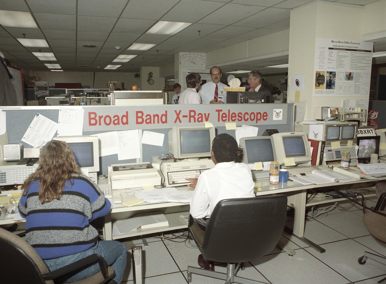
The primary objective of the STS-35 mission was round the clock observation of the celestial sphere in ultraviolet and X-Ray astronomy with the Astro-1 observatory which consisted of four telescopes: the Hopkins Ultraviolet Telescope (HUT); the Wisconsin Ultraviolet Photo-Polarimeter Experiment (WUPPE); the Ultraviolet Imaging Telescope (UIT); and the Broad Band X-Ray Telescope (BBXRT). The Huntsville Operations Support Center (HOSC) Spacelab Payload Operations Control Center (SL POCC) at the Marshall Space Flight Center (MSFC) was the air/ground communication channel used between the astronauts and ground control teams during the Spacelab missions. Teams of controllers and researchers directed on-orbit science operations, sent commands to the spacecraft, received data from experiments aboard the Space Shuttle, adjusted mission schedules to take advantage of unexpected science opportunities or unexpected results, and worked with crew members to resolve problems with their experiments. Due to loss of data used for pointing and operating the ultraviolet telescopes, MSFC ground teams were forced to aim the telescopes with fine tuning by the flight crew. This photo captures the activity of WUPPE (Wisconsin Ultraviolet Photo-Polarimeter Experiment) data review at the Science Operations Area during the mission. This image shows mission activities at the Broad Band X-Ray Telescope (BBXRT) Work Station in the Science Operations Area (SOA).
Multiple exposure of Rendezvous Docking Simulator. Francis B. Smith, described the simulator as follows: The rendezvous and docking operation of the Gemini spacecraft with the Agena and of the Apollo Command Module with the Lunar Excursion Module have been the subject of simulator studies for several years. This figure illustrates the Gemini-Agena rendezvous docking simulator at Langley. The Gemini spacecraft was supported in a gimbal system by an overhead crane and gantry arrangement which provided 6 degrees of freedom - roll, pitch, yaw, and translation in any direction - all controllable by the astronaut in the spacecraft. Here again the controls fed into a computer which in turn provided an input to the servos driving the spacecraft so that it responded to control motions in a manner which accurately simulated the Gemini spacecraft. -- Published in Barton C. Hacker and James M. Grimwood, On the Shoulders of Titans: A History of Project Gemini, NASA SP-4203 Francis B. Smith, Simulators for Manned Space Research, Paper presented at the 1966 IEEE International convention, March 21-25, 1966.
KENNEDY SPACE CENTER, FLA. - At the Shuttle Landing Facility on NASA’s Kennedy Space Center, a ribbon-cutting dedicated the new NASA Air Traffic Control Tower. From left are James H. Jones, Space Gateway Support President William A. Sample, Center Director Jim Kennedy, External Relations Director Lisa Malone, Center Operations Director Scott D. Kerr, and KSC Safety Aviation Officer Albert E. Taff. The structure rises 110 feet over the midpoint of the runway and offers air traffic controllers a magnificent 360-degree view of Kennedy Space Center, Cape Canaveral Air Force Station and north Brevard County. It replaces the small, portable tower installed at the edge of the runway in 1986. The new control tower will manage all landings and departures from the SLF, including air traffic within the Kennedy Space Center-Cape Canaveral restricted airspace. The facility provides a 24-hour weather-observing facility providing official hourly weather observations for the SLF and the Cape Canaveral vicinity, including special observations for all launches and landings. State-of-the-art, weather-observing equipment has been installed for Space Shuttle landings and for serving conventional aircraft landing at the SLF. At this location, weather observers will have a multi-directional view of the weather conditions at the runway and Launch Complex 39.
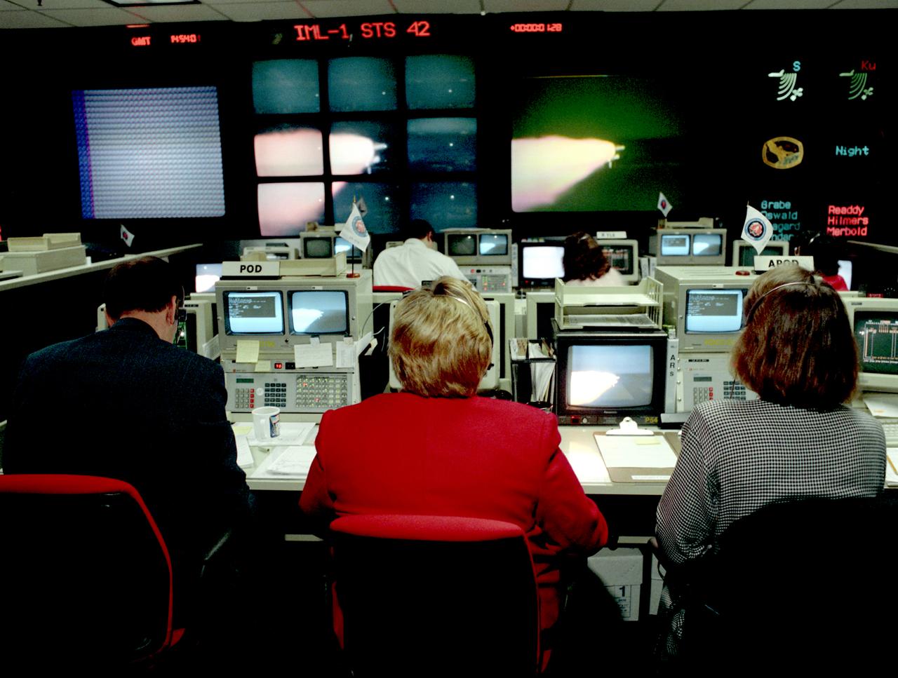
The primary payload for Space Shuttle Mission STS-42, launched January 22, 1992, was the International Microgravity Laboratory-1 (IML-1), a pressurized manned Spacelab module. The goal of IML-1 was to explore in depth the complex effects of weightlessness of living organisms and materials processing. Around-the-clock research was performed on the human nervous system's adaptation to low gravity and effects of microgravity on other life forms such as shrimp eggs, lentil seedlings, fruit fly eggs, and bacteria. Materials processing experiments were also conducted, including crystal growth from a variety of substances such as enzymes, mercury iodide and a virus. The Huntsville Operations Support Center (HOSC) Spacelab Payload Operations Control Center (SL POCC) at the Marshall Space Flight Center (MSFC) was the air/ground communication channel used between the astronauts aboard the Spacelab and scientists, researchers, and ground control teams during the Spacelab missions. The facility made instantaneous video and audio communications possible for scientists on the ground to follow the progress and to send direct commands of their research almost as if they were in space with the crew. Teams of controllers and researchers directed on-orbit science operations, sent commands to the spacecraft, received data from experiments aboard the Space Shuttle, adjusted mission schedules to take advantage of unexpected science opportunities or unexpected results, and worked with crew members to resolve problems with their experiments. In this photograph the Payload Operations Director (POD) views the launch.
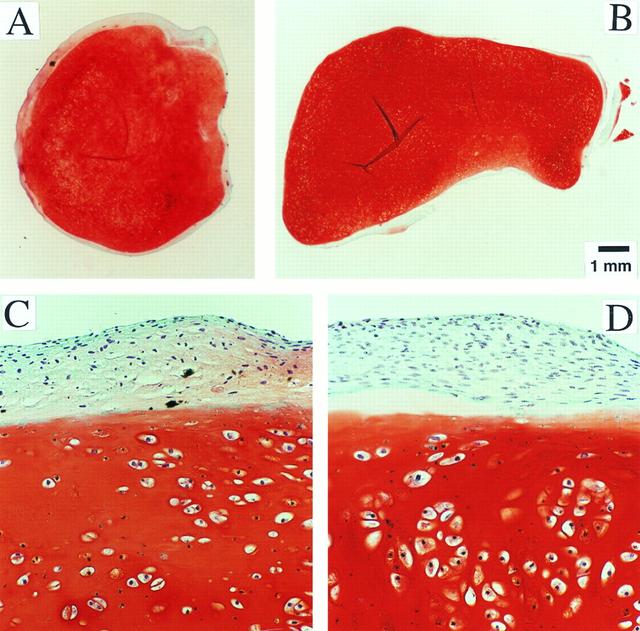
Dr. Lisa E. Freed of the Massachusetts Institute of Technology and her colleagues have reported that initially disc-like specimens of cartilage tend to become spherical in space, demonstrating that tissues can grow and differentiate into distinct structures in microgravity. The Mir Increment 3 (Sept. 16, 1996 - Jan. 22, 1997) samples were smaller, more spherical, and mechanically weaker than Earth-grown control samples. These results demonstrate the feasibility of microgravity tissue engineering and may have implications for long human space voyages and for treating musculoskeletal disorders on earth. Constructs grown on Mir (A) tended to become more spherical, whereas those grown on Earth (B) maintained their initial disc shape. These findings might be related to differences in cultivation conditions, i.e., videotapes showed that constructs floated freely in microgravity but settled and collided with the rotating vessel wall at 1g (Earth's gravity). In particular, on Mir the constructs were exposed to uniform shear and mass transfer at all surfaces such that the tissue grew equally in all directions, whereas on Earth the settling of discoid constructs tended to align their flat circular areas perpendicular to the direction of motion, increasing shear and mass transfer circumferentially such that the tissue grew preferentially in the radial direction. A and B are full cross sections of constructs from Mir and Earth groups shown at 10-power. C and D are representative areas at the construct surfaces enlarged to 200-power. They are stained red with safranin-O. NASA-sponsored bioreactor research has been instrumental in helping scientists to better understand normal and cancerous tissue development. The work is sponsored by NASA's Office of Biological and Physical Research. The bioreactor is managed by the Biotechnology Cell Science Program at NASA's Johnson Space Center (JSC). Photo credit: Proceedings of the National Academy of Sciences.
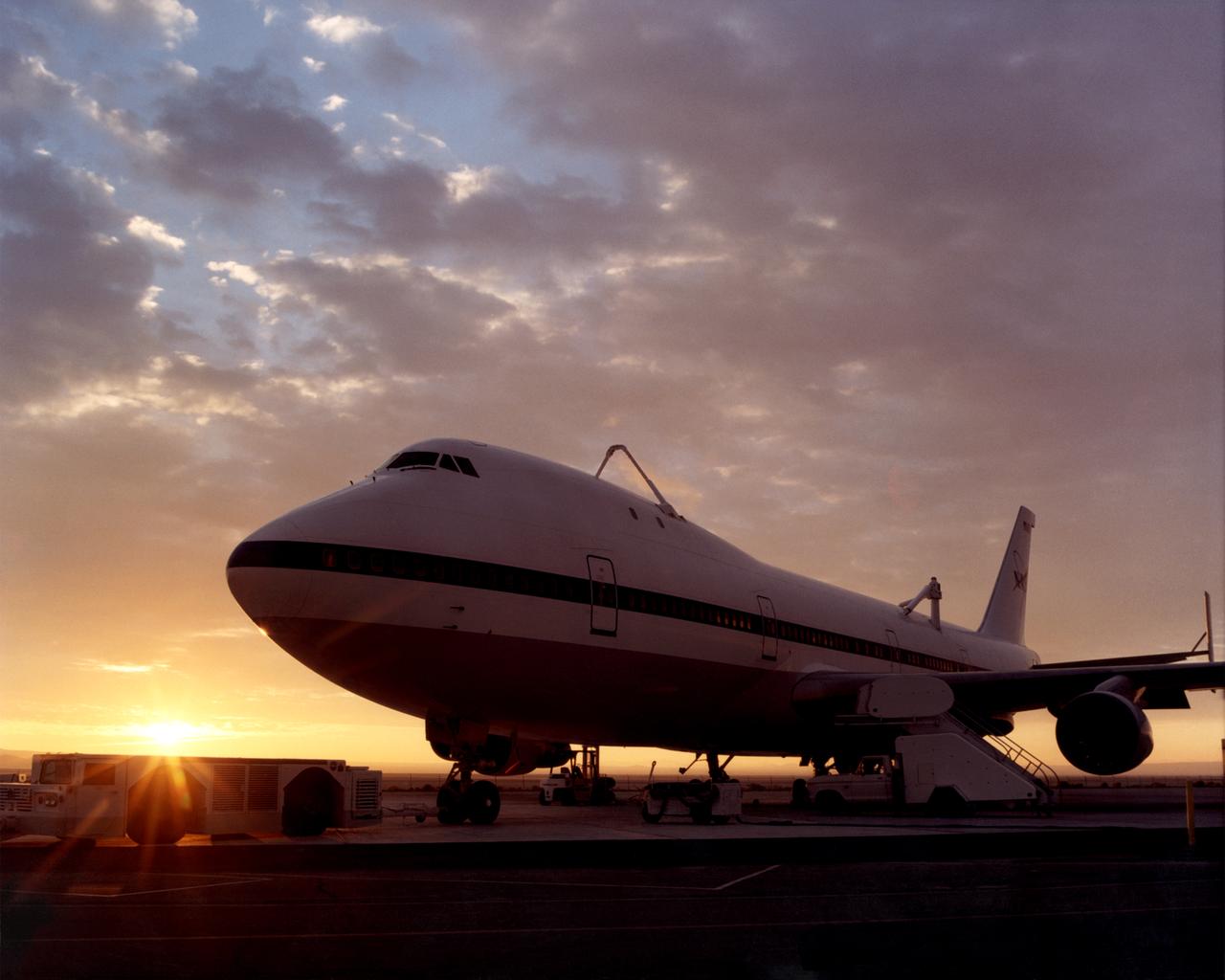
One of NASA’s two modified Boeing 747 Shuttle Carrier Aircraft is bathed in the morning Sun at NASA’s Dryden Flight Research Center at Edwards, California. The modified jumbo jetliners are used to ferry the Space Shuttle orbiters between Dryden and the Kennedy Space Center in Florida and Boeing’s Reusable Space Systems modification facility at Palmdale, California. Features which distinguish the two SCAs from standard 747 jetliners are three struts, with associated interior structural strengthening, which protrude from the top of the fuselage (two aft, one forward) on which the orbiter is attached, and two additional vertical stabilizers, one on each end of the standard horizontal stabilizer, to enhance directional stability. All interior furnishings and equipment aft of the forward No. 1 doors have also been removed to reduce weight. The two SCAs are under the operational control of NASA's Johnson Space Center, Houston, Texas.
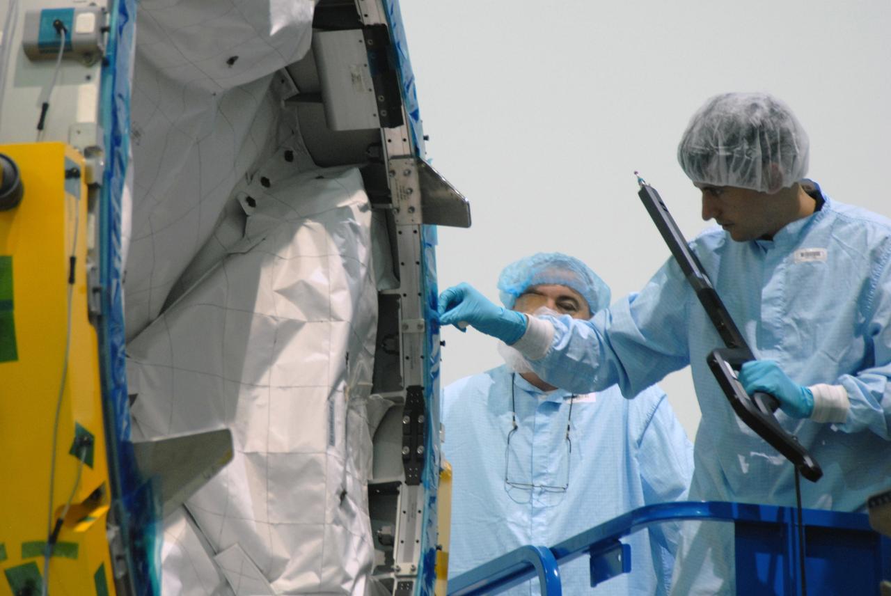
CAPE CANAVERAL, Fla. – In the Space Station Processing Facility at NASA's Kennedy Space Center in Florida, workers take measurements of the Cupola module being aligned with the Tranquility module for assembly. Cupola and Tranquility are the payload for space shuttle Endeavour's STS-130 mission to the International Space Station. The module was built for the European Space Agency by Alenia Spazio in Turin, Italy. When attached to the Tranquility Node 3 module, Cupola will resemble a circular bay window that will provide a vastly improved view of the station's exterior. Just under 10 feet in diameter, the module will accommodate two crew members and portable workstations that can control station and robotic activities. The multi-directional view will allow the crew to monitor spacewalks and docking operations, as well as provide a spectacular view of Earth and other celestial objects. Endeavour is targeted to launch Feb. 4, 2010. Photo credit: NASA/Jim Grossmann
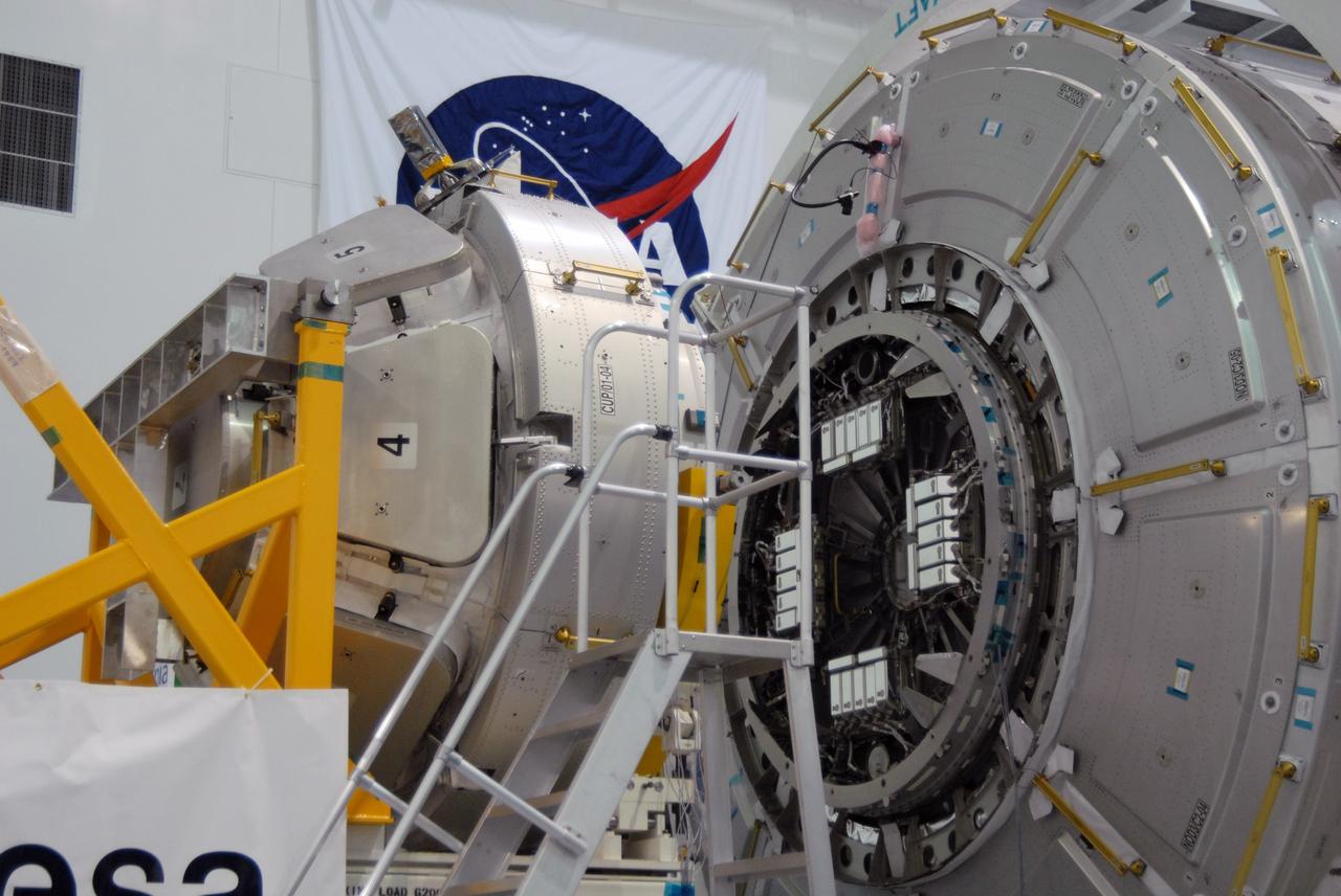
CAPE CANAVERAL, Fla. – In the Space Station Processing Facility at NASA's Kennedy Space Center in Florida, NASA's Cupola module, at left, is being aligned with the Tranquility module, at right, for assembly. Cupola and Tranquility are the payload for space shuttle Endeavour's STS-130 mission to the International Space Station. The module was built for the European Space Agency by Alenia Spazio in Turin, Italy. When attached to the Tranquility Node 3 module, Cupola will resemble a circular bay window that will provide a vastly improved view of the station's exterior. Just under 10 feet in diameter, the module will accommodate two crew members and portable workstations that can control station and robotic activities. The multi-directional view will allow the crew to monitor spacewalks and docking operations, as well as provide a spectacular view of Earth and other celestial objects. Endeavour is targeted to launch Feb. 4, 2010. Photo credit: NASA/Jim Grossmann
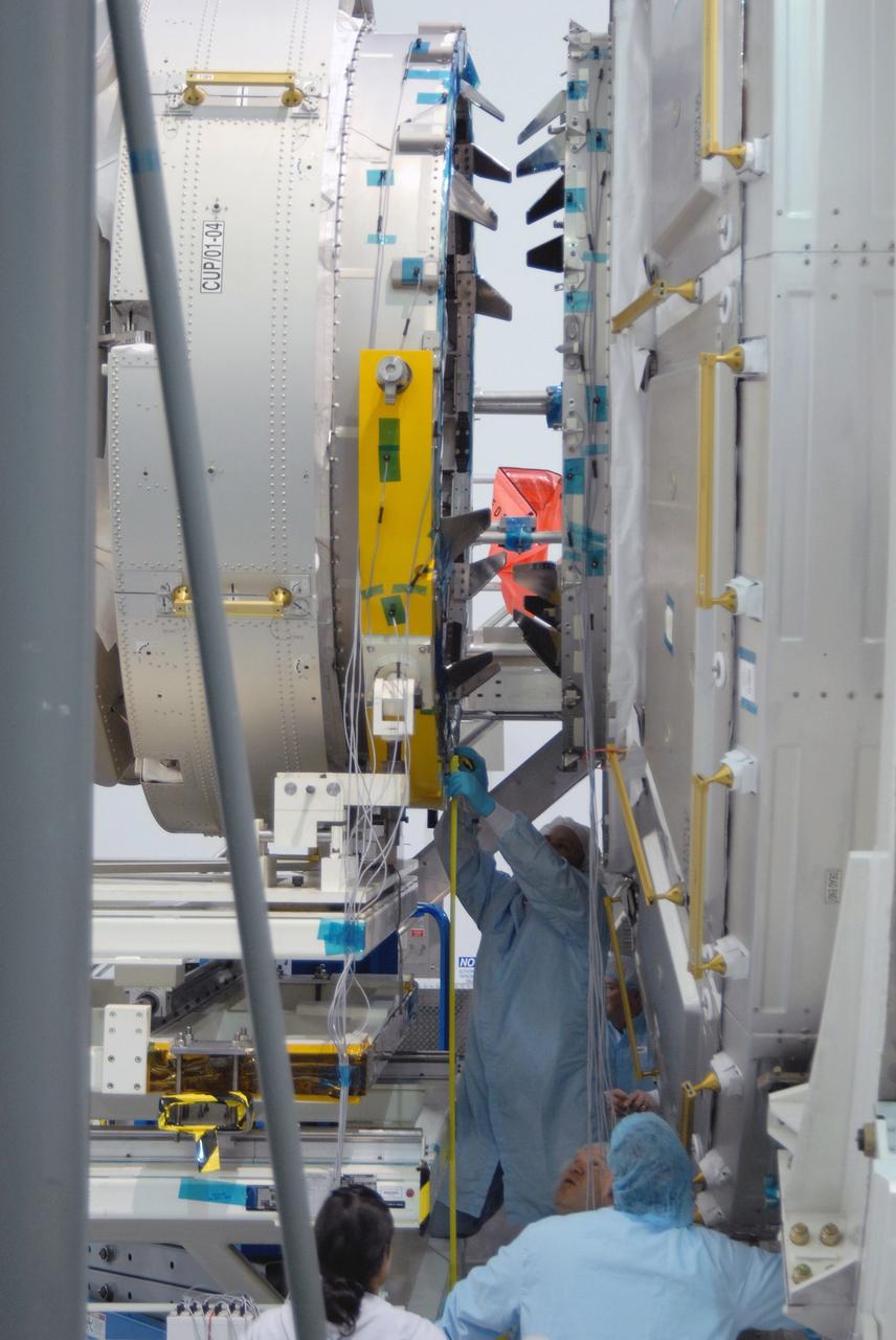
CAPE CANAVERAL, Fla. – In the Space Station Processing Facility at NASA's Kennedy Space Center in Florida, a worker checks the alignment of the Cupola module, at left, with the Tranquility module, at right. Cupola and Tranquility are the payload for space shuttle Endeavour's STS-130 mission to the International Space Station. The module was built for the European Space Agency by Alenia Spazio in Turin, Italy. When attached to the Tranquility Node 3 module, Cupola will resemble a circular bay window that will provide a vastly improved view of the station's exterior. Just under 10 feet in diameter, the module will accommodate two crew members and portable workstations that can control station and robotic activities. The multi-directional view will allow the crew to monitor spacewalks and docking operations, as well as provide a spectacular view of Earth and other celestial objects. Endeavour is targeted to launch Feb. 4, 2010. Photo credit: NASA/Jim Grossmann
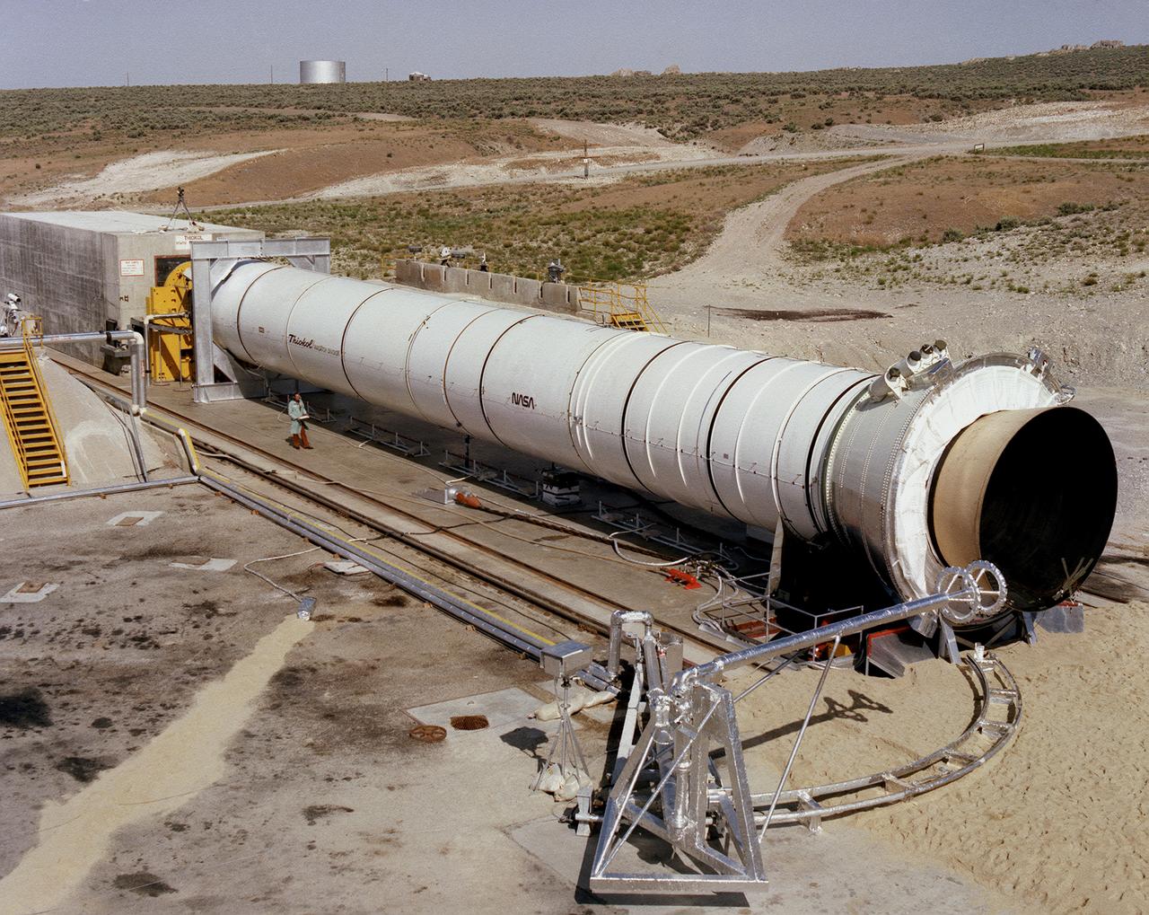
This is a photograph of the solid rocket booster's (SRB's) Qualification Motor-1 (QM-1) being prepared for a static firing in a test stand at the Morton Thiokol Test Site in Wasatch, Utah, showing the aft end of the booster. The twin boosters provide the majority of thrust for the first two minutes of flight, about 5.8 million pounds, augmenting the Shuttle's main propulsion system during liftoff. The major design drivers for the solid rocket motors (SRM's) were high thrust and reuse. The desired thrust was achieved by using state-of-the-art solid propellant and by using a long cylindrical motor with a specific core design that allows the propellant to burn in a carefully controlled marner. Under the direction of the Marshall Space Flight Center, the SRM's are provided by the Morton Thiokol Corporation.
CAPE CANAVERAL, Fla. – In NASA Kennedy Space Center's Space Station Processing Facility, the Cupola module is being mated to the Tranquility node on the work stand. Cupola and Tranquility are the payload for space shuttle Endeavour's STS-130 mission to the International Space Station. The module was built for the European Space Agency by Alenia Spazio in Turin, Italy. When attached to the Tranquility Node 3 module, Cupola will resemble a circular bay window that will provide a vastly improved view of the station's exterior. Just under 10 feet in diameter, the module will accommodate two crew members and portable workstations that can control station and robotic activities. The multi-directional view will allow the crew to monitor spacewalks and docking operations, as well as provide a spectacular view of Earth and other celestial objects. Endeavour is targeted to launch Feb. 4, 2010. Photo credit: NASA/Cory Huston
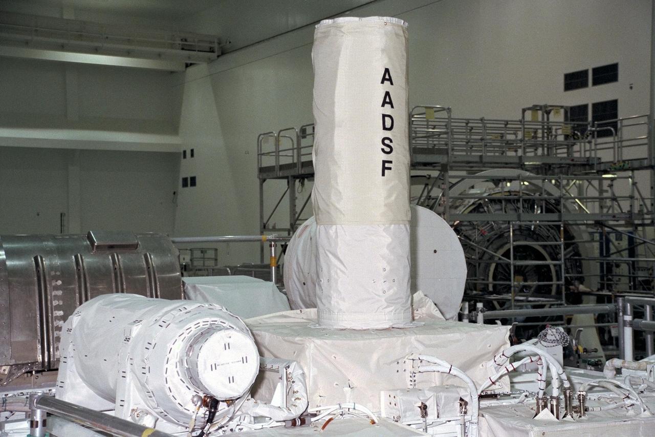
United States Microgravity Payload-4 (USMP-4) experiments are prepared to be flown on Space Shuttle mission STS-87 in the Space Station Processing Facility at Kennedy Space Center (KSC). The vertical tube in the center of the photo is the Advanced Automated Directional Solidification Furnace (AADSF), which will be used by researchers to study the solidification of semiconductor materials in microgravity. Scientists will be able to better understand how microgravity influences the solidification process of these materials and develop better methods for controlling that process during future Space flights and Earth-based production. To its left is MEPHISTO, the French acronym for a cooperative American-French investigation of the fundamentals of crystal growth. All STS-87 experiments are scheduled for launch on Nov. 19 from KSC
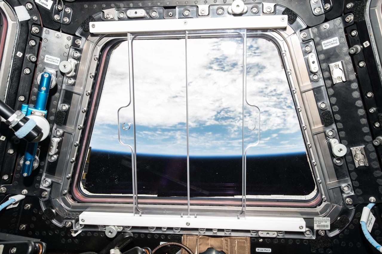
ISS042E227564 (02/08/2015) --- A view of the Earth from the International Space Station's Cupola widow on Feb. 8, 2015. The Cupola, a small, dome-shaped module has seven windows -- six around the sides and one on top -- that can be shuttered when not in use to protect the ISS from micrometeoroids and the harsh space environment. The windows are made of fused silica and borosilicate glass panes, with temperature-sensing elements and window heaters. It is attached to the Tranquility Node 3 module, Cupola provides a vastly improved view of the station's exterior. Just under ten feet in diameter, the module accommodates two crew members and portable workstations that can control station and robotic Canada arm activities. The multi-directional view allows the crew to monitor spacewalks and docking operations, as well as provide a spectacular view of Earth and other celestial objects.
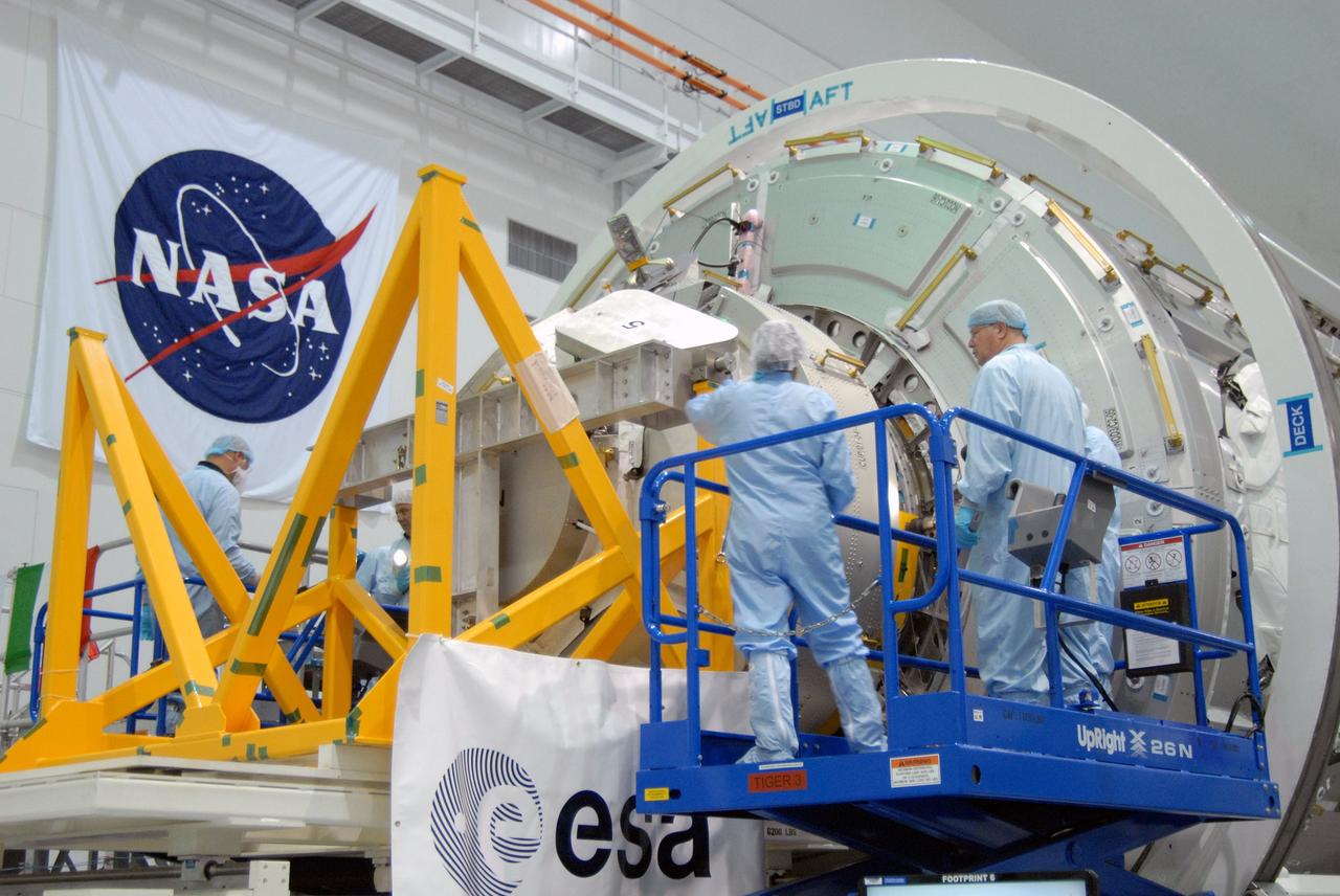
CAPE CANAVERAL, Fla. – In NASA Kennedy Space Center's Space Station Processing Facility, the Cupola module is being mated to the Tranquility node on the work stand. Cupola and Tranquility are the payload for space shuttle Endeavour's STS-130 mission to the International Space Station. The module was built for the European Space Agency by Alenia Spazio in Turin, Italy. When attached to the Tranquility Node 3 module, Cupola will resemble a circular bay window that will provide a vastly improved view of the station's exterior. Just under 10 feet in diameter, the module will accommodate two crew members and portable workstations that can control station and robotic activities. The multi-directional view will allow the crew to monitor spacewalks and docking operations, as well as provide a spectacular view of Earth and other celestial objects. Endeavour is targeted to launch Feb. 4, 2010. Photo credit: NASA/Cory Huston
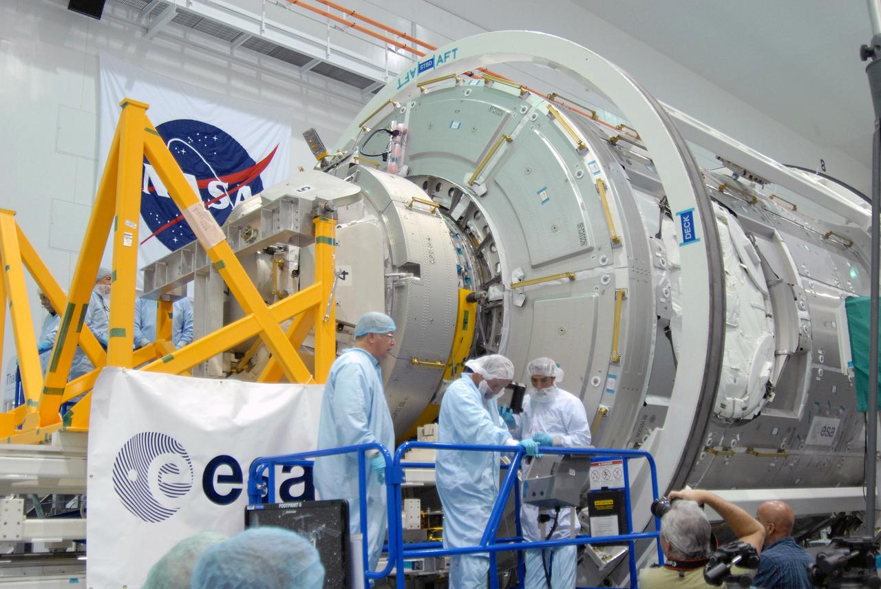
CAPE CANAVERAL, Fla. – In NASA Kennedy Space Center's Space Station Processing Facility, the Cupola module is being mated to the Tranquility node on the work stand. Cupola and Tranquility are the payload for space shuttle Endeavour's STS-130 mission to the International Space Station. The module was built for the European Space Agency by Alenia Spazio in Turin, Italy. When attached to the Tranquility Node 3 module, Cupola will resemble a circular bay window that will provide a vastly improved view of the station's exterior. Just under 10 feet in diameter, the module will accommodate two crew members and portable workstations that can control station and robotic activities. The multi-directional view will allow the crew to monitor spacewalks and docking operations, as well as provide a spectacular view of Earth and other celestial objects. Endeavour is targeted to launch Feb. 4, 2010. Photo credit: NASA/Cory Huston
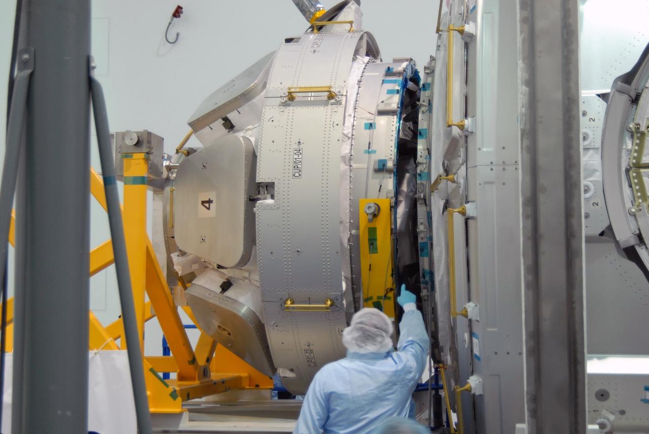
CAPE CANAVERAL, Fla. – In the Space Station Processing Facility at NASA's Kennedy Space Center in Florida, a worker checks the alignment of the Cupola module, at left, with the Tranquility module, at right. Cupola and Tranquility are the payload for space shuttle Endeavour's STS-130 mission to the International Space Station. The module was built for the European Space Agency by Alenia Spazio in Turin, Italy. When attached to the Tranquility Node 3 module, Cupola will resemble a circular bay window that will provide a vastly improved view of the station's exterior. Just under 10 feet in diameter, the module will accommodate two crew members and portable workstations that can control station and robotic activities. The multi-directional view will allow the crew to monitor spacewalks and docking operations, as well as provide a spectacular view of Earth and other celestial objects. Endeavour is targeted to launch Feb. 4, 2010. Photo credit: NASA/Jim Grossmann
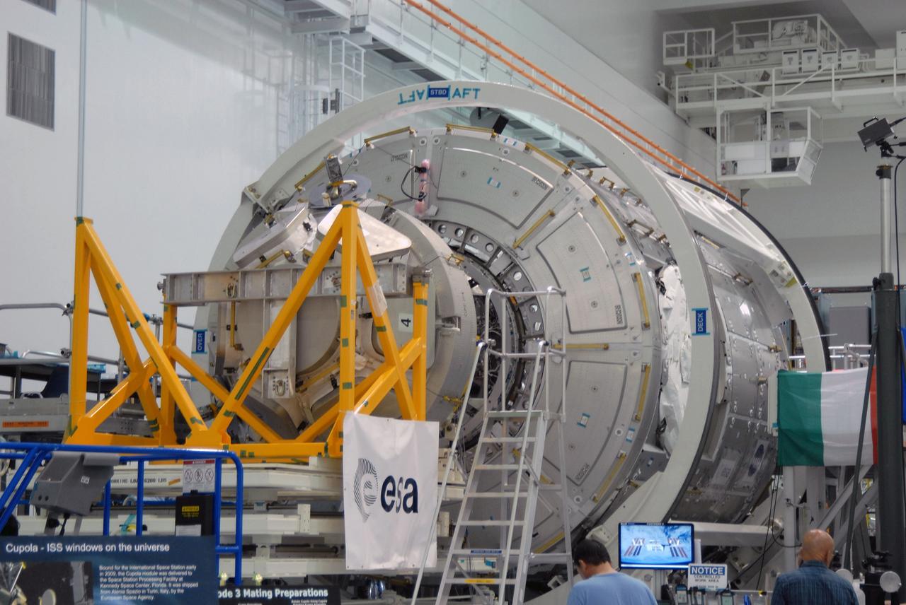
CAPE CANAVERAL, Fla. – In the Space Station Processing Facility at NASA's Kennedy Space Center in Florida, NASA's Cupola module is being aligned with the Tranquility module for assembly. Cupola and Tranquility are the payload for space shuttle Endeavour's STS-130 mission to the International Space Station. The module was built for the European Space Agency by Alenia Spazio in Turin, Italy. When attached to the Tranquility Node 3 module, Cupola will resemble a circular bay window that will provide a vastly improved view of the station's exterior. Just under 10 feet in diameter, the module will accommodate two crew members and portable workstations that can control station and robotic activities. The multi-directional view will allow the crew to monitor spacewalks and docking operations, as well as provide a spectacular view of Earth and other celestial objects. Endeavour is targeted to launch Feb. 4, 2010. Photo credit: NASA/Jim Grossmann
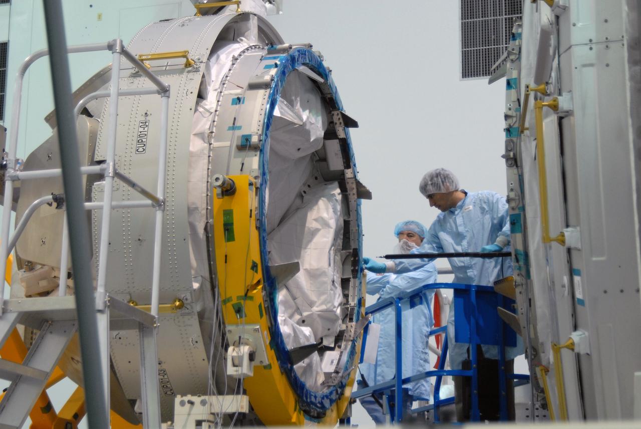
CAPE CANAVERAL, Fla. – In the Space Station Processing Facility at NASA's Kennedy Space Center in Florida, workers check the Cupola module, at left, being aligned with the Tranquility module, at right, for assembly. Cupola and Tranquility are the payload for space shuttle Endeavour's STS-130 mission to the International Space Station. The module was built for the European Space Agency by Alenia Spazio in Turin, Italy. When attached to the Tranquility Node 3 module, Cupola will resemble a circular bay window that will provide a vastly improved view of the station's exterior. Just under 10 feet in diameter, the module will accommodate two crew members and portable workstations that can control station and robotic activities. The multi-directional view will allow the crew to monitor spacewalks and docking operations, as well as provide a spectacular view of Earth and other celestial objects. Endeavour is targeted to launch Feb. 4, 2010. Photo credit: NASA/Jim Grossmann
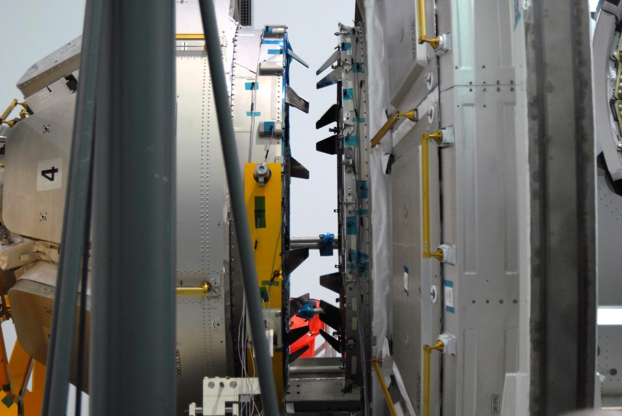
CAPE CANAVERAL, Fla. – In the Space Station Processing Facility at NASA's Kennedy Space Center in Florida, NASA's Cupola module, at left, aligns with the Tranquility module, at right. Cupola and Tranquility are the payload for space shuttle Endeavour's STS-130 mission to the International Space Station. The module was built for the European Space Agency by Alenia Spazio in Turin, Italy. When attached to the Tranquility Node 3 module, Cupola will resemble a circular bay window that will provide a vastly improved view of the station's exterior. Just under 10 feet in diameter, the module will accommodate two crew members and portable workstations that can control station and robotic activities. The multi-directional view will allow the crew to monitor spacewalks and docking operations, as well as provide a spectacular view of Earth and other celestial objects. Endeavour is targeted to launch Feb. 4, 2010. Photo credit: NASA/Jim Grossmann
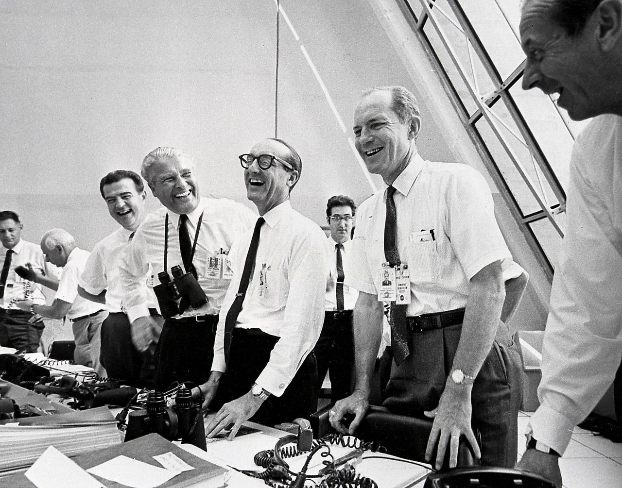
NASA officials, (left to right) Charles W. Mathews; Dr. Wernher von Braun, Director, Marshall Space Flight Center (MSFC); Dr. George E. Mueller, Associate Administrator for Marned Space Flight; and Air Force Lt. General Samuel C. Phillips, Apollo Program Director celebrate the successful launch of Apollo 11 in the control room at Kennedy Space Center (KSC) on July 16, 1969. Boosted by the Saturn V launch vehicle, the Apollo 11 mission with a crew of three: Astronauts Neil A. Armstrong, Michael Collins, and Edwin E. Aldrin, made the first manned lunar landing. The Saturn V vehicle was developed by Marshall Space Flight Center (MSFC) under the direction of Dr. von Braun.
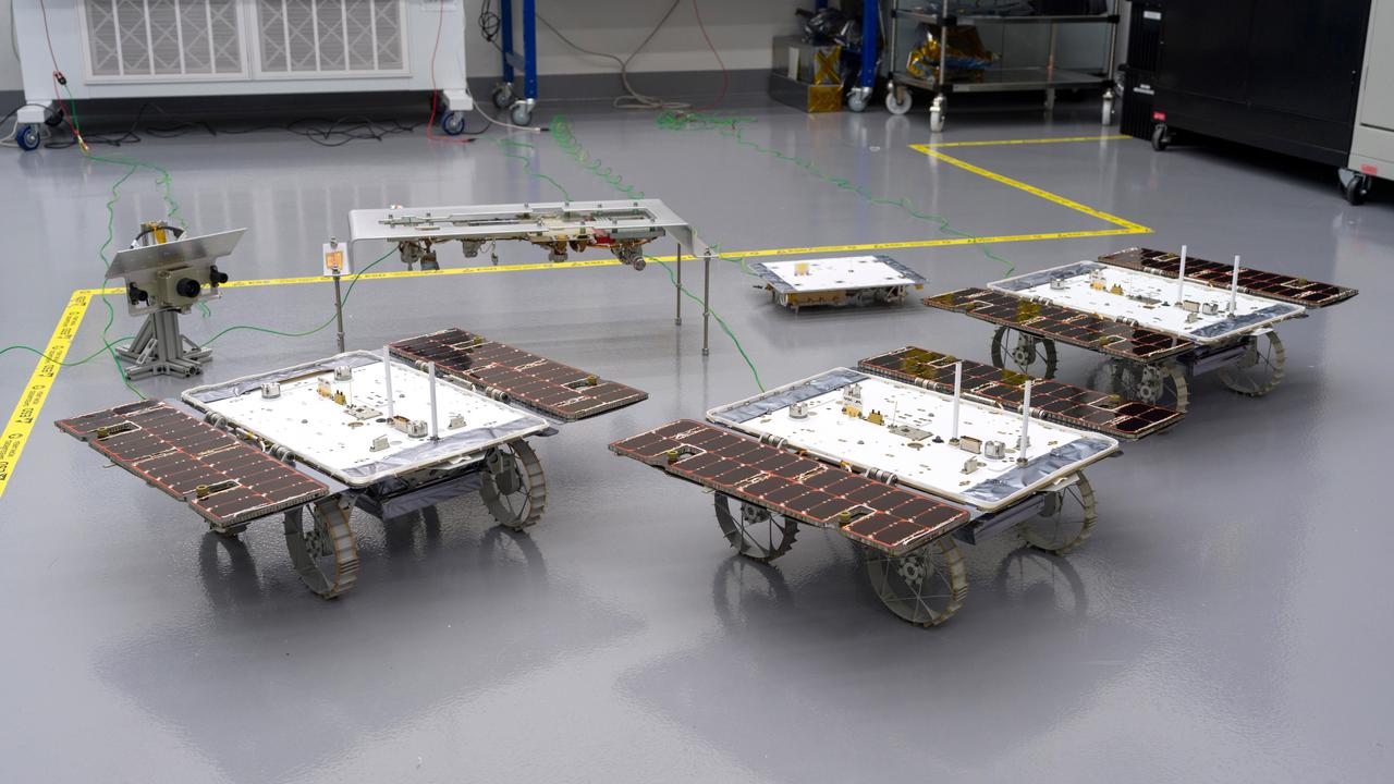
Three small rovers bound for the Moon – part of NASA's CADRE (Cooperative Autonomous Distributed Robotic Exploration) technology demonstration – are arrayed in a clean room at the agency's Jet Propulsion Laboratory in Southern California on Jan. 26, 2024. CADRE is designed to show that a group of robotic spacecraft can work together autonomously as a team to accomplish tasks and record data without constant direction from mission controllers on Earth. Each about the size of a carry-on suitcase, the rovers will ride to the Moon's surface aboard a lander equipped with the hardware elements that sit behind them in this image: from left, the situational awareness camera assembly, one of the deployers that will lower the rovers onto the lunar surface, and the base station with which the rovers will communicate via mesh network radios. https://photojournal.jpl.nasa.gov/catalog/PIA26346