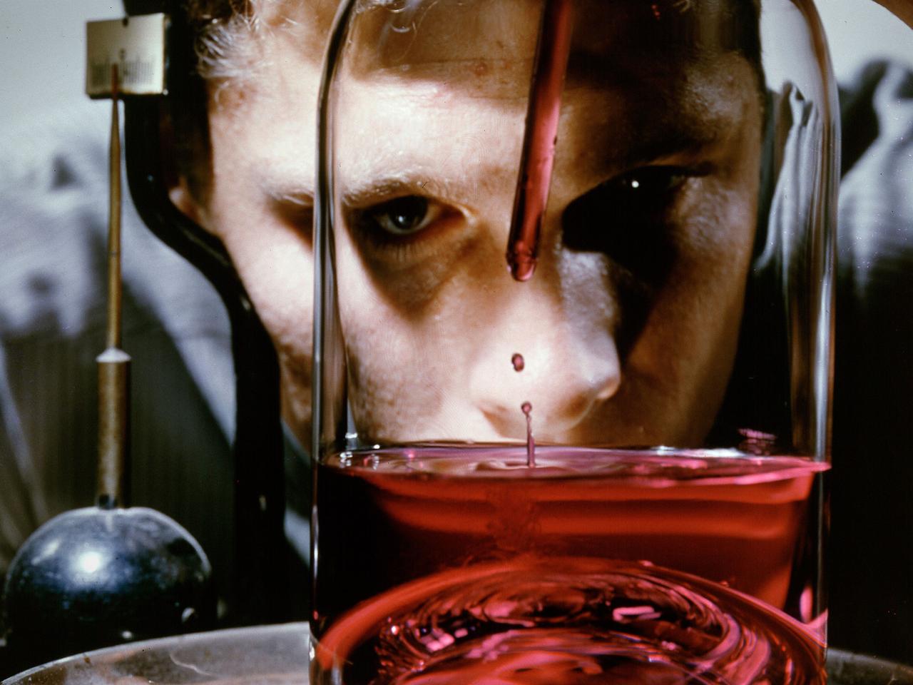
A researcher fills a small container used to represent a liquid hydrogen tank in preparation for a microgravity test in the 2.2-Second Drop Tower at the National Aeronautics and Space Administration (NASA) Lewis Research Center. For over a decade, NASA Lewis endeavored to make liquid hydrogen a viable propellant. Hydrogen’s light weight and high energy made it very appealing for rocket propulsion. One of the unknowns at the time was the behavior of fluids in the microgravity of space. Rocket designers needed to know where the propellant would be inside the fuel tank in order to pump it to the engine. NASA Lewis utilized sounding rockets, research aircraft, and the 2.2 Second Drop Tower to study liquids in microgravity. The drop tower, originally built as a fuel distillation tower in 1948, descended into a steep ravine. By early 1961 the facility was converted into an eight-floor, 100-foot tower connected to a shop and laboratory space. Small glass tanks, like this one, were installed in experiment carts with cameras to film the liquid’s behavior during freefall. Thousands of drop tower tests in the early 1960s provided an increased understanding of low-gravity processes and phenomena. The tower only afforded a relatively short experiment time but was sufficient enough that the research could be expanded upon using longer duration freefalls on sounding rockets or aircraft. The results of the early experimental fluid studies verified predictions made by Lewis researchers that the total surface energy would be minimized in microgravity.
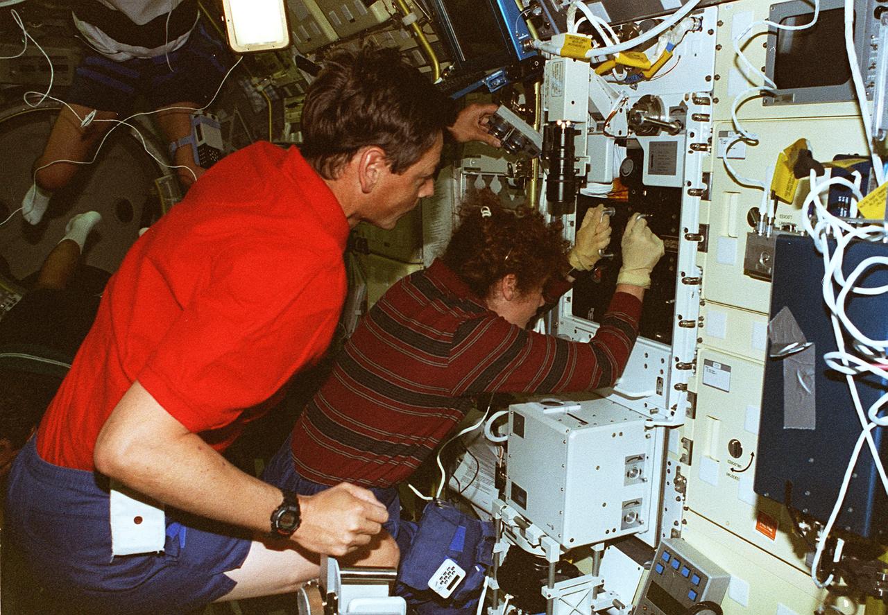
STS078-306-035 (20 June - 7 July 1996) --- Astronaut Susan J. Helms, payload commander, and payload specialist Jean-Jacques Favier, representing the French Space Agency (CNES), insert a test container into the Bubble Drop Particle Unit (BDPU) in the Life and Microgravity Spacelab (LMS-1) Science Module aboard the Space Shuttle Columbia. The fluid in the chamber is heated and the fluid processes are observed by use of three internal cameras mounted inside the BDPU. Investigations in this facility will help characterize interfacial processes involving either bubbles, drops, liquid columns or liquid layers.
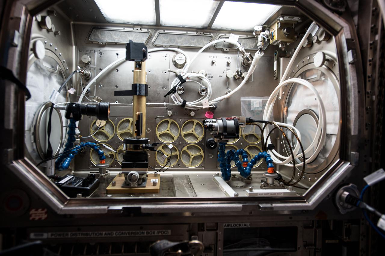
iss064e002379 (1/15/2017) --- Photo documentation of Inertial Spreading with Vibration and Water Coalescence (Drop Vibration) experiment hardware set up inside the Microgravity Science Glovebox (MSG) aboard the International Space Station (ISS). Inertial Spreading with Vibration and Water Coalescence (Drop Vibration) examines the behavior of big liquid drops whose perimeter of contact, called the contact line, moves rapidly as the drops change shape either forced by vibration or freely by merger.
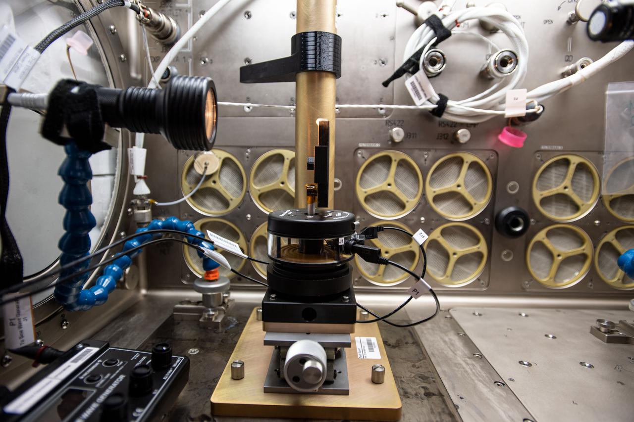
iss064e002375 (1/15/2017) --- Photo documentation of Inertial Spreading with Vibration and Water Coalescence (Drop Vibration) experiment hardware set up inside the Microgravity Science Glovebox (MSG) aboard the International Space Station (ISS). Inertial Spreading with Vibration and Water Coalescence (Drop Vibration) examines the behavior of big liquid drops whose perimeter of contact, called the contact line, moves rapidly as the drops change shape either forced by vibration or freely by merger.
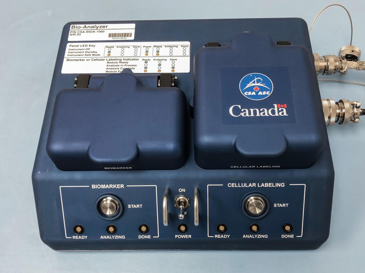
jsc2019e017352 (3/1/2019) --- The Canadian Space Agency's Bio-Analyzer is a liquid sample analysis device that will help astronauts on board the International Space Station accelerate the process of scientific data collection. Using just a few drops of liquid, it quickly returns key biomedical analyses.
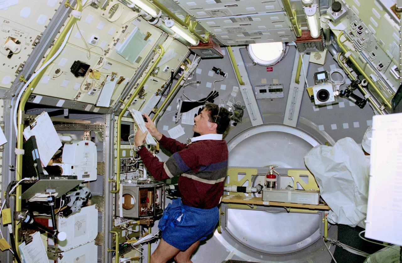
STS083-302-002 (4-8 April 1997) --- At the MidDeck Glove Box (MGBX), astronaut Donald A. Thomas, mission specialist, prepares to conduct the Internal Flows in Free Drops (IFFD) experiment. The IFFD is meant to study drops of several liquids, including water, water/glycerin and silicon oil. Flows within the drops and shape and stability are studied under varying acoustic pressure. The MGBX is the overall facility that holds experiments on materials that are not approved for study in the open Spacelab environment.
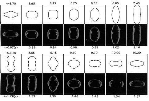
Apfel's excellent match: This series of photos shows a water drop containing a surfactant (Triton-100) as it experiences a complete cycle of superoscillation on U.S. Microgravity Lab-2 (USML-2; October 1995). The time in seconds appears under the photos. The figures above the photos are the oscillation shapes predicted by a numerical model. The time shown with the predictions is nondimensional. Robert Apfel (Yale University) used the Drop Physics Module on USML-2 to explore the effect of surfactants on liquid drops. Apfel's research of surfactants may contribute to improvements in a variety of industrial processes, including oil recovery and environmental cleanup.
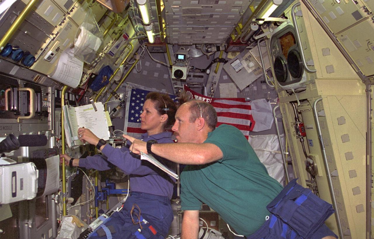
STS073-229-014 (20 October - 5 November 1995) --- Astronauts Kathryn C. Thornton, STS-73 payload commander, and Kenneth D. Bowersox, mission commander, observe a liquid drop's activity at the Drop Physics Module (DPM) in the science module aboard the Earth-orbiting Space Shuttle Columbia. The drop is partially visible at the center of the left edge of the frame. The two were joined by three other NASA astronauts and two guest researchers for almost 16-days of in-orbit research in support of the U.S. Microgravity Laboratory (USML-2) mission.
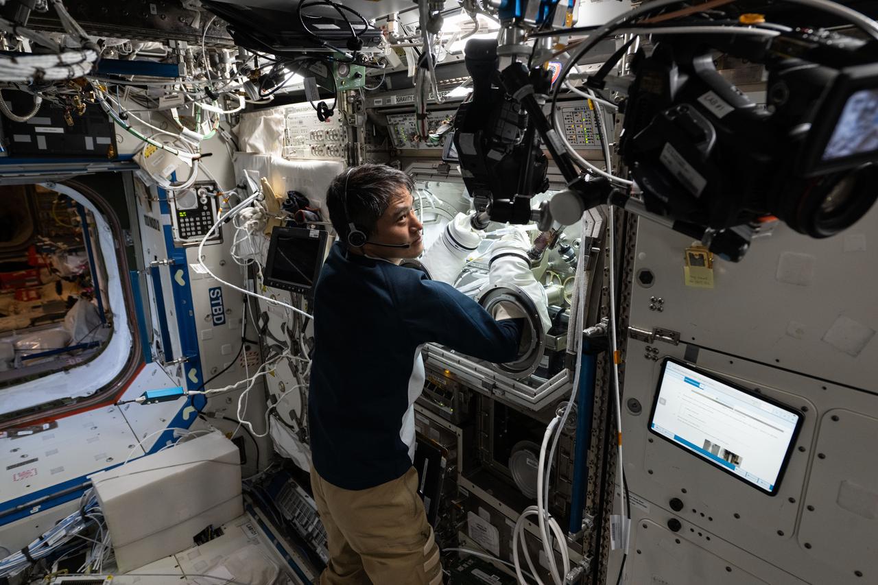
iss073e0177064 (6/11/2025) --- Scientists can study protein solutions without interference from container walls and gravity driven forces present on Earth using the space station’s Ring Sheared Drop module. The device pins a drop of liquid between two rings and holds it in place with surface tension. JAXA astronaut Takuya Onishi sets up for Ring Sheared Drop-IBP-2, a study of the behavior of protein fluids in microgravity. The investigation uses the module to test computer models to predict fluid behavior that could lead to improved processes for manufacturing pharmaceuticals, 3D printing, food processing, and microelectronics.
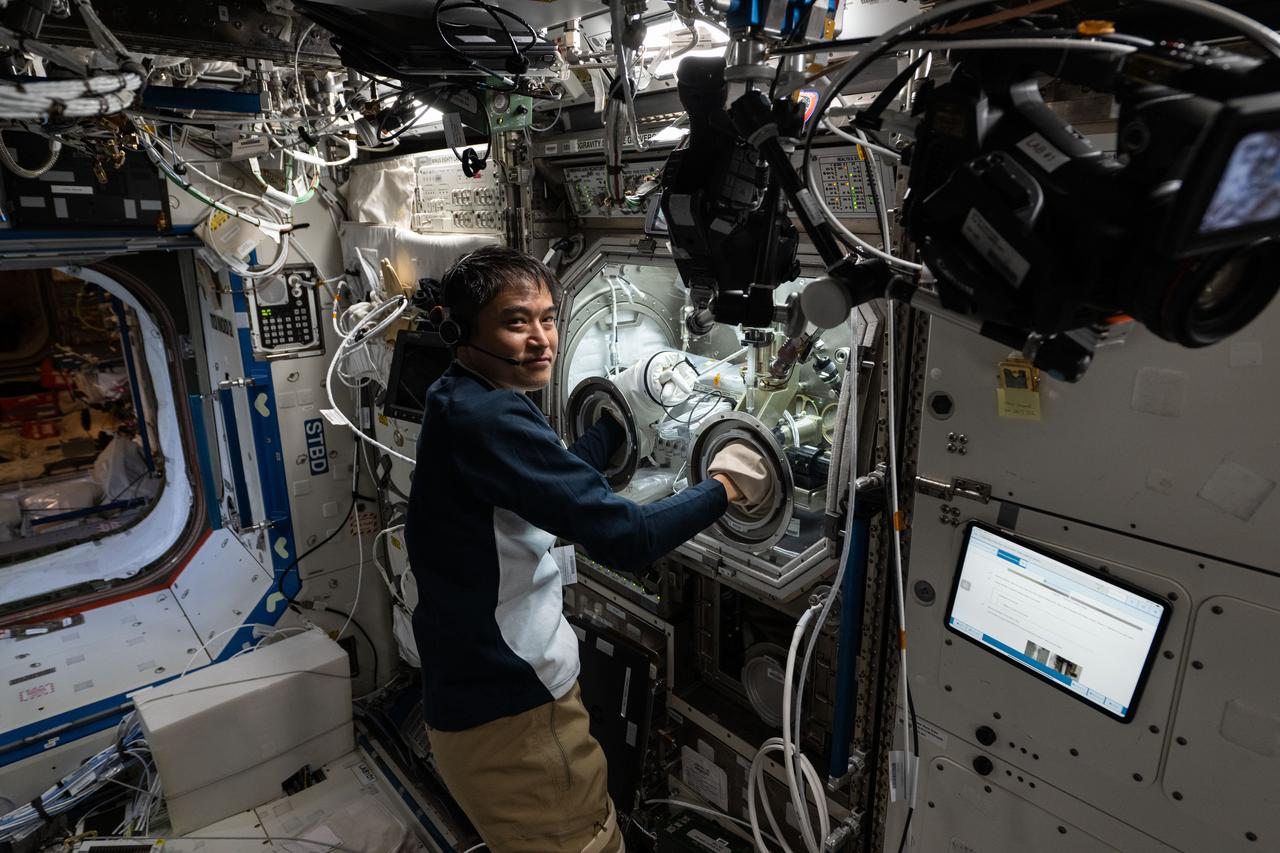
iss073e0177065 (6/11/2025) --- Scientists can study protein solutions without interference from container walls and gravity driven forces present on Earth using the space station’s Ring Sheared Drop module. The device pins a drop of liquid between two rings and holds it in place with surface tension. JAXA (Japan Aerospace Exploration Agency) astronaut and Expedition 73 Commander Takuya Onishi sets up for Ring Sheared Drop-IBP-2, a study of the behavior of protein fluids in microgravity. The investigation uses the module to test computer models to predict fluid behavior that could lead to improved processes for manufacturing pharmaceuticals, 3D printing, food processing, and microelectronics.
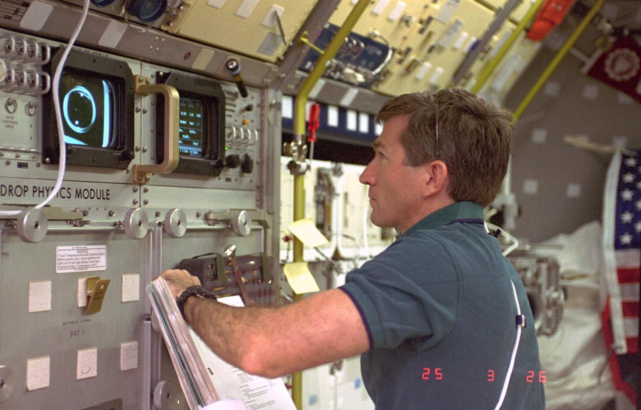
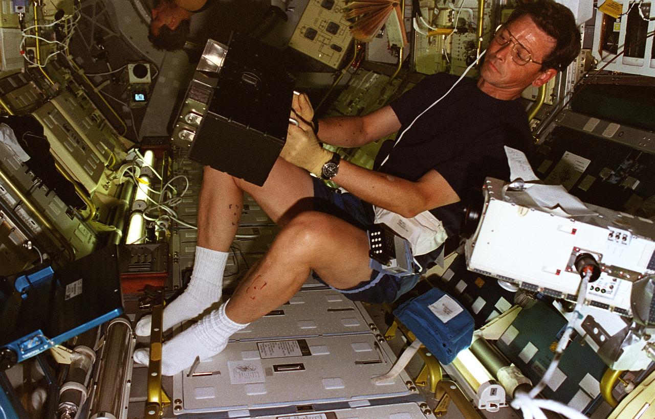
STS073-225-036 (20 October-5 November 1995) --- Payload specialist Fred W. Leslie monitors the response of a liquid drop at the Drop Physics Module (DPM) in the U.S. Microgravity Laboratory (USML-2) science module aboard the Space Shuttle Columbia. Leslie joined another guest researcher and five NASA astronauts for almost 16-days of Earth-orbit research in support of the mission.
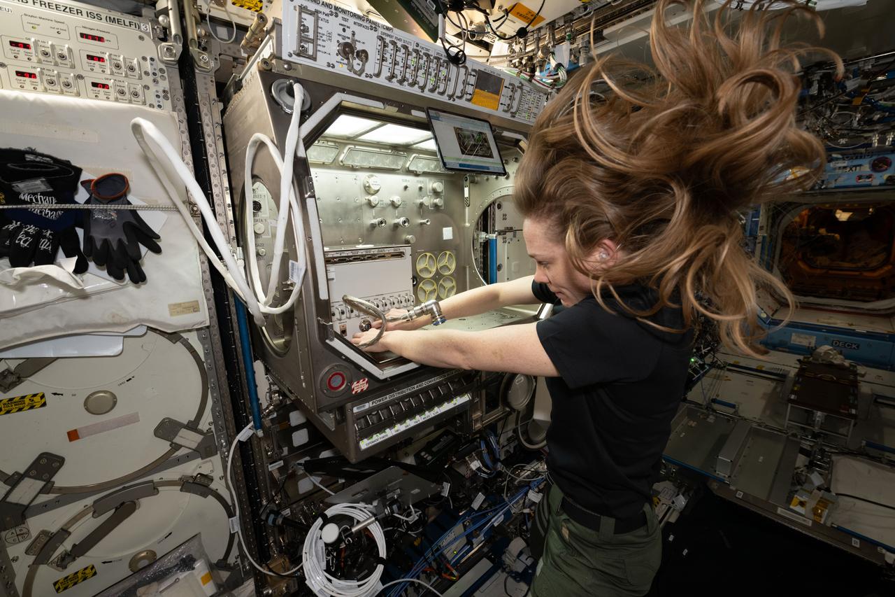
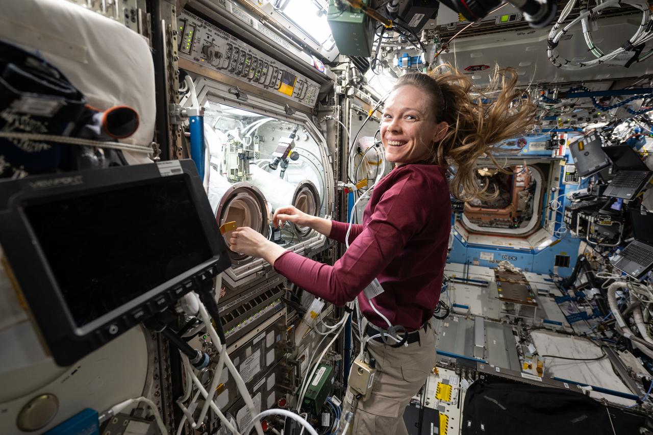
iss073e0134929 (6/9/2025) ---NASA astronaut Nichole Ayers sets up the station’s Ring Sheared Drop module. This system makes it possible to study liquid protein solutions without using containers, eliminating interactions between the solutions and container walls that can affect results. Ring Sheared Drop-IBP-2 studies the behavior of protein fluids in microgravity and tests computer models to predict that fluid’s behavior. Better models could help could advance manufacturing processes in space and on Earth for producing next-generation medicines for treating cancers and other diseases.NASA astronaut Nichole Ayers sets up the station’s Ring Sheared Drop module. This system makes it possible to study liquid protein solutions without using containers, eliminating interactions between the solutions and container walls that can affect results. Ring Sheared Drop-IBP-2 studies the behavior of protein fluids in microgravity and tests computer models to predict that fluid’s behavior. Better models could help could advance manufacturing processes in space and on Earth for producing next-generation medicines for treating cancers and other diseases.
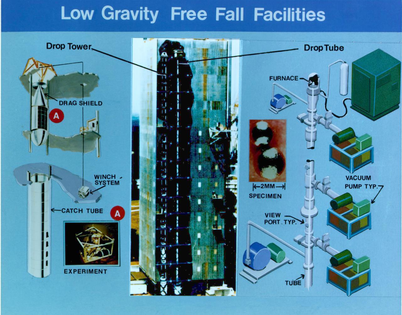
Composite of Marshall Space Flight Center's Low-Gravity Free Fall Facilities.These facilities include a 100-meter drop tower and a 100-meter drop tube. The drop tower simulates in-flight microgravity conditions for up to 4.2 seconds for containerless processing experiments, immiscible fluids and materials research, pre-flight hardware design test and flight experiment simulation. The drop tube simulates in-flight microgravity conditions for up to 4.6 seconds and is used extensively for ground-based microgravity convection research in which extremely small samples are studied. The facility can provide deep undercooling for containerless processing experiments that require materials to remain in a liquid phase when cooled below the normal solidification temperature.
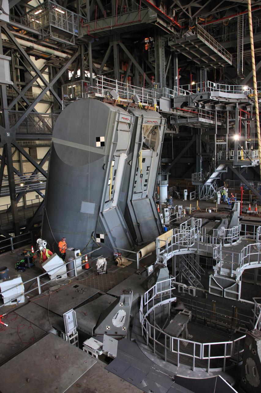
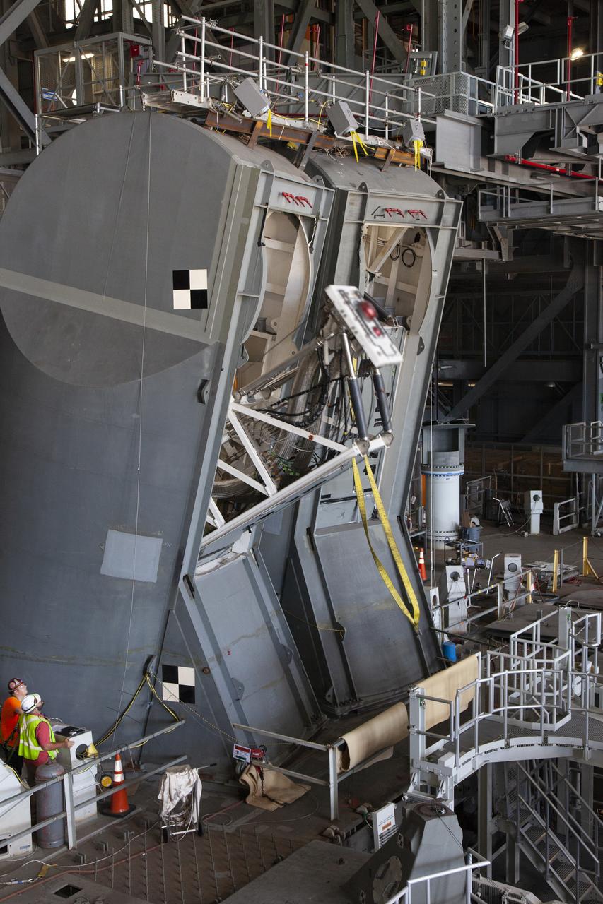
Preparations are underway to conduct a drop test of the Tail Service Mast Umbilicals (TSMU) for NASA’s Space Launch System (SLS) rocket on the mobile launcher in High Bay 3 of the Vehicle Assembly Building at NASA’s Kennedy Space Center in Florida on June 19, 2019. The 35-foot-tall TSMUs will connect to the SLS core stage aft section and provide liquid oxygen and liquid hydrogen fluid lines and electrical cable connections to the core stage engine section to support propellant handling during prelaunch operations. The drop test is being performed to ensure that the umbilicals will disconnect before launch of the SLS carrying Orion on its first uncrewed mission, Artemis 1, from Launch Complex 39B. Exploration Ground Systems and Engineering are completing the tests.
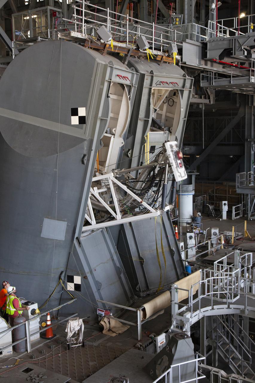
A drop test of the Tail Service Mast Umbilicals (TSMU) for NASA’s Space Launch System (SLS) rocket is underway on the mobile launcher in High Bay 3 of the Vehicle Assembly Building at NASA’s Kennedy Space Center in Florida on June 19, 2019. The 35-foot-tall TSMUs will connect to the SLS core stage aft section and provide liquid oxygen and liquid hydrogen fluid lines and electrical cable connections to the core stage engine section to support propellant handling during prelaunch operations. The drop test is being performed to ensure that the umbilicals will disconnect before launch of the SLS carrying Orion on its first uncrewed mission, Artemis 1, from Launch Complex 39B. Exploration Ground Systems and Engineering are completing the tests.
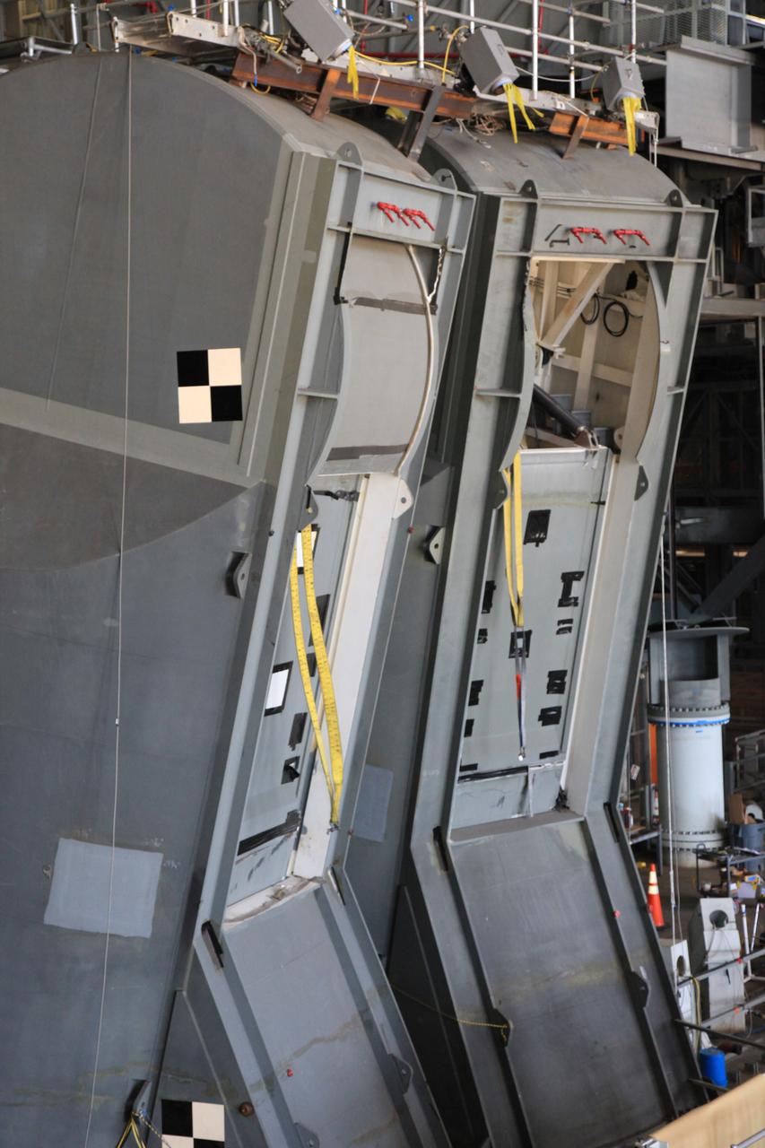
Preparations are underway to conduct a drop test of the Tail Service Mast Umbilicals (TSMU) for NASA’s Space Launch System (SLS) rocket on the mobile launcher in High Bay 3 of the Vehicle Assembly Building at NASA’s Kennedy Space Center in Florida on June 19, 2019. The 35-foot-tall TSMUs will connect to the SLS core stage aft section and provide liquid oxygen and liquid hydrogen fluid lines and electrical cable connections to the core stage engine section to support propellant handling during prelaunch operations. The drop test is being performed to ensure that the umbilicals will disconnect before launch of the SLS carrying Orion on its first uncrewed mission, Artemis 1, from Launch Complex 39B. Exploration Ground Systems and Engineering are completing the tests.
A drop test of the Tail Service Mast Umbilicals (TSMU) for NASA’s Space Launch System (SLS) rocket is underway on the mobile launcher in High Bay 3 of the Vehicle Assembly Building at NASA’s Kennedy Space Center in Florida on June 19, 2019. The 35-foot-tall TSMUs will connect to the SLS core stage aft section and provide liquid oxygen and liquid hydrogen fluid lines and electrical cable connections to the core stage engine section to support propellant handling during prelaunch operations. The drop test is being performed to ensure that the umbilicals will disconnect before launch of the SLS carrying Orion on its first uncrewed mission, Artemis 1, from Launch Complex 39B. Exploration Ground Systems and Engineering are completing the tests.
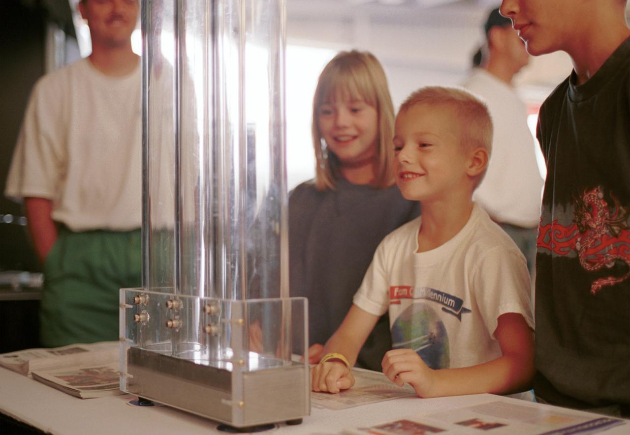
An entranced youngster watches a demonstration of the enhanced resilience of undercooled metal alloys as compared to conventional alloys. Steel bearings are dropped onto plates made of steel, titanium alloy, and zirconium liquid metal alloy, so-called because its molecular structure is amorphous and not crystalline. The bearing on the liquid metal plate bounces for a minute or more longer than on the other plates. Experiments aboard the Space Shuttle helped scientists refine their understanding of the physical properties of certain metal alloys when undercooled (i.e., kept liquid below their normal solidification temperature). This new knowledge then allowed scientists to modify a terrestrial production method so they can now make limited quantities marketed under the Liquid Metal trademark. The exhibit was a part of the NASA outreach activity at AirVenture 2000 sponsored by the Experimental Aircraft Association in Oshkosh, WI.
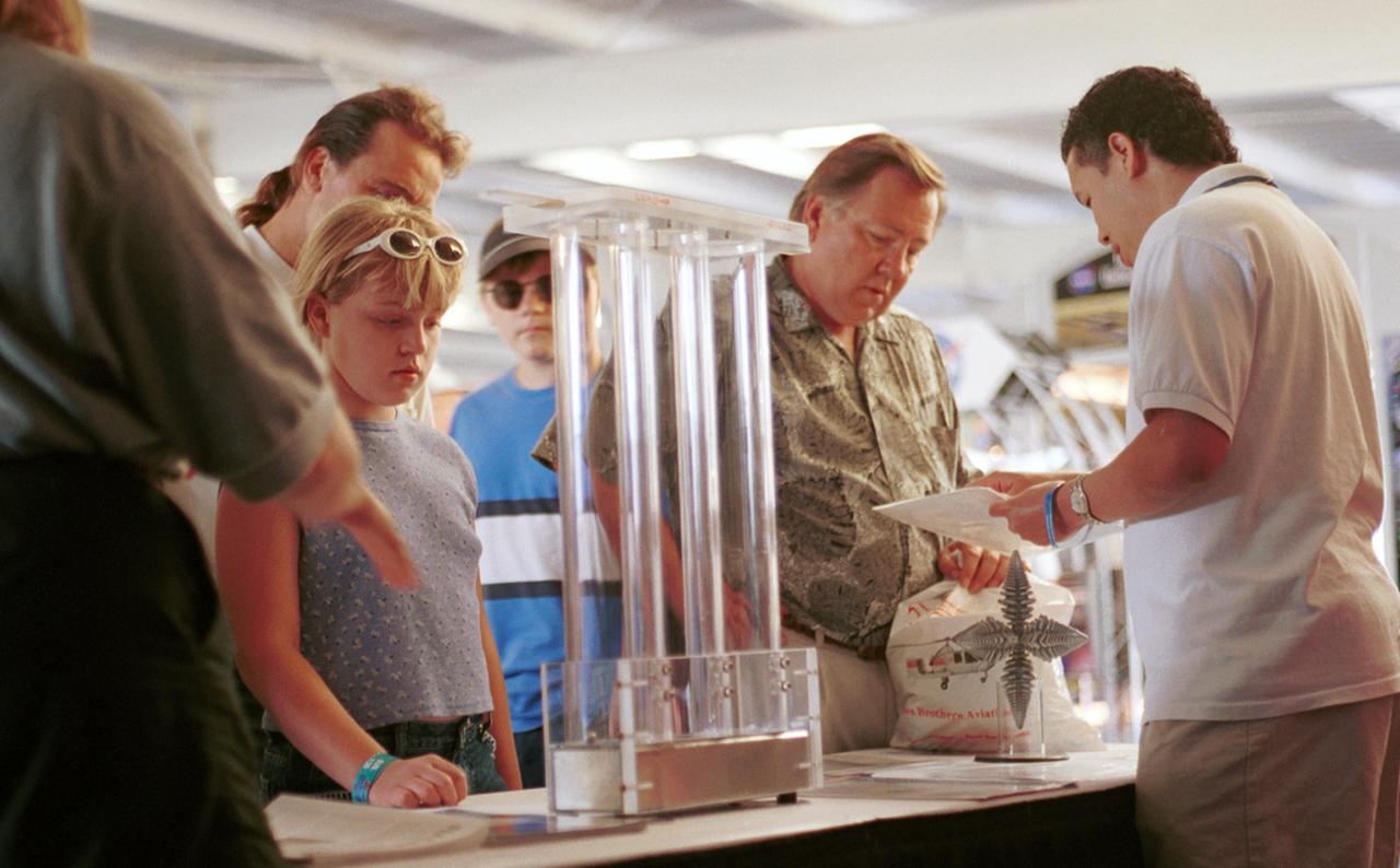
Paul Luz (right), an aerospace flight system engineer at NASA's Marshall Space Flight Center (MSFC), discusses microgravity research with a visitor at AirVenture 2000. Part of the NASA exhibits included demonstration of knowledge gained from micorgravity research aboard the Space Shuttle. These include liquid metal (Liquid metal demonstrator is three plastic drop tubes at center) and dendritic growth (in front of Luz), both leading to improvements in processes on Earth. The exhibit was part of the NASA outreach activity at AirVenture 2000 sponsored by the Experimental Aircraft Association in Oshkosh, WI.
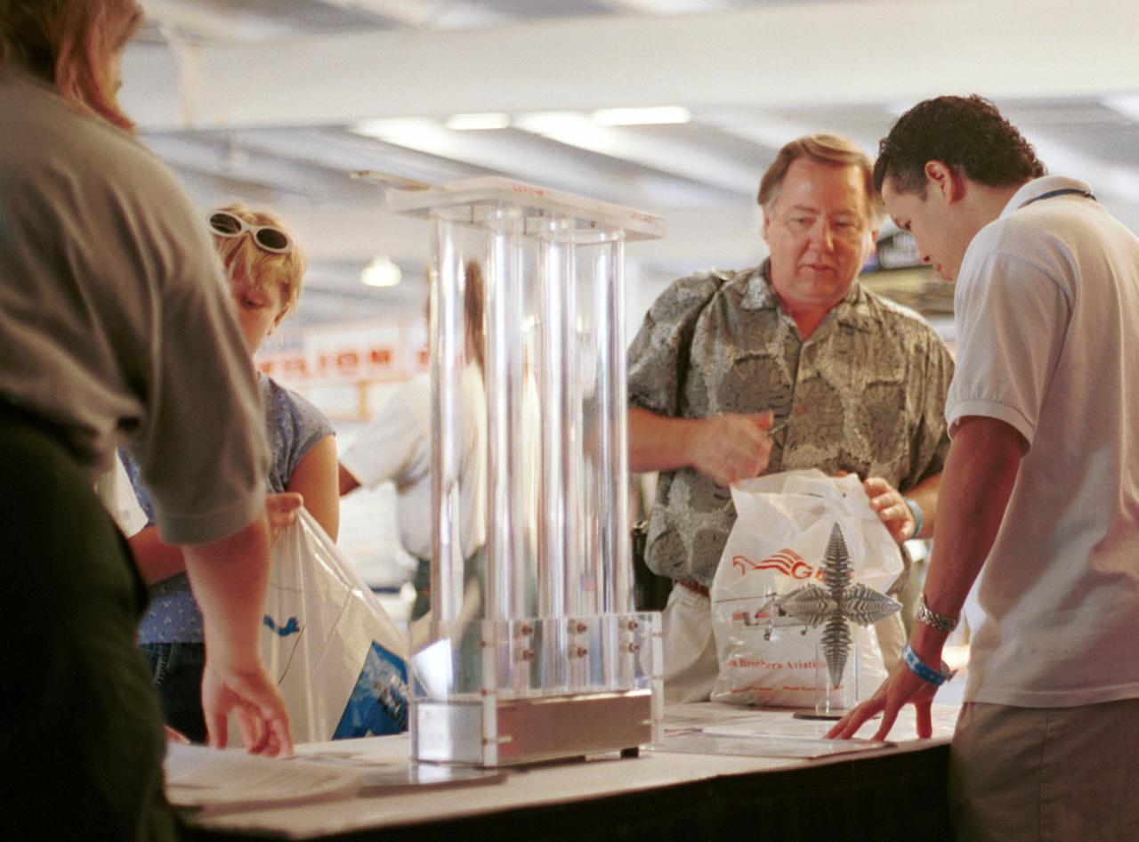
Paul Luz (right), an aerospace flight systems engineer at NASA's Marshall Space Flight Center (MSFC), takes a question from a visitor as they discuss microgravity research at AirVenture 2000. Part of the NASA exhibits included demonstrations of knowledge gained from microgravity research aboard the Space Shuttle. These include liquid metal (liquid metal demonstrator is three plastic drop tubes at center) and dendritic growth (in front of Luz), both leading to improvements in processes of Earth. The exhibit was part of the NASA outreach activity at AirVenture 2000 sponsored by the Experimental Aircraft Association in Oshkosh, WI.
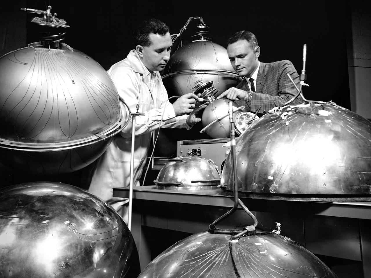
An engineer and technician at the National Aeronautics and Space Administration (NASA) Lewis Research Center install the instrumentation on spherical fuel tanks for an investigation of the behavior of liquids in microgravity. Lewis researchers were undertaking a broad effort to study the heat transfer properties of high energy propellants such as liquid hydrogen in microgravity. In the center’s 2.2-Second Drop Tower they investigated the wetting characteristics of liquid and the liquid-vapor configurations, and predicted the equilibrium state in microgravity conditions. Lewis was also conducting a series microgravity investigations which launched 9-inch diameter spherical dewars, seen here, on an Aerobee sounding rocket. A camera inside the rocket filmed the liquid hydrogen’s behavior during its 4 to 7 minutes of freefall. The researchers concluded, however, that they needed to extend the weightlessness period to obtain better results. So they designed an experiment to be launched on an Atlas missile that would provide 21 minutes of weightlessness. The experiment was flight qualified at Lewis. The 36-percent full liquid hydrogen stainless steel dewar was launched on the Atlas on February 25, 1964. The instrumentation measured temperature, pressure, vacuum, and liquid level. Temperature instrumentation indicated wall drying during the freefall. The resultant pressure-rise characteristics were similar to those used for the normal-gravity test.
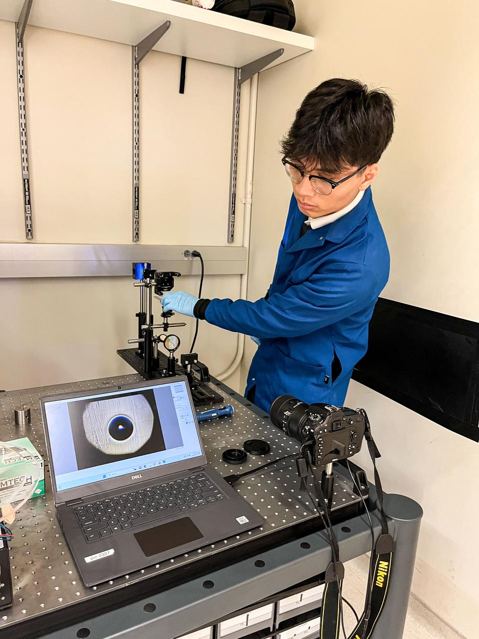
jsc2023e055884 (9/26/2023) --- Trinh Huynh uses a quantitative Schlieren system to measure the deformation of the mucus-like gel around a liquid drop. The Gaucho Lung investigation will study fluid transport within gel-coated tubes to learn more about treatment programs for respiratory distress syndrome and develop new contamination control strategies. Image courtesy of University of California, Santa Barbara.
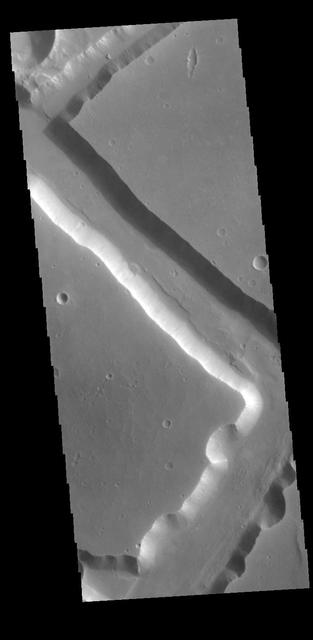
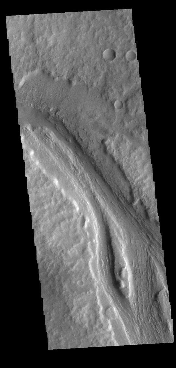
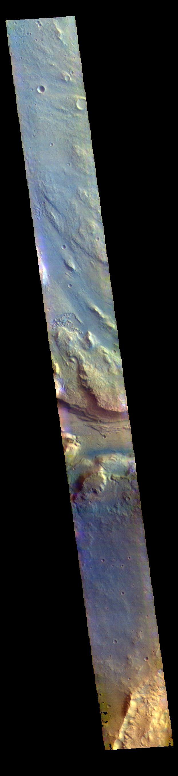
Located on the western margin of Lunae Planum, Sacra Fossae is a group of linear depressions. The right angle turns and uniform width seen in this VIS image indicate that these channels were formed by faulting rather than liquid flow. Two bounding faults with a down-dropped interior are called graben. Orbit Number: 71244 Latitude: 17.7623 Longitude: 288.309 Instrument: VIS Captured: 2018-01-05 09:06 https://photojournal.jpl.nasa.gov/catalog/PIA22373
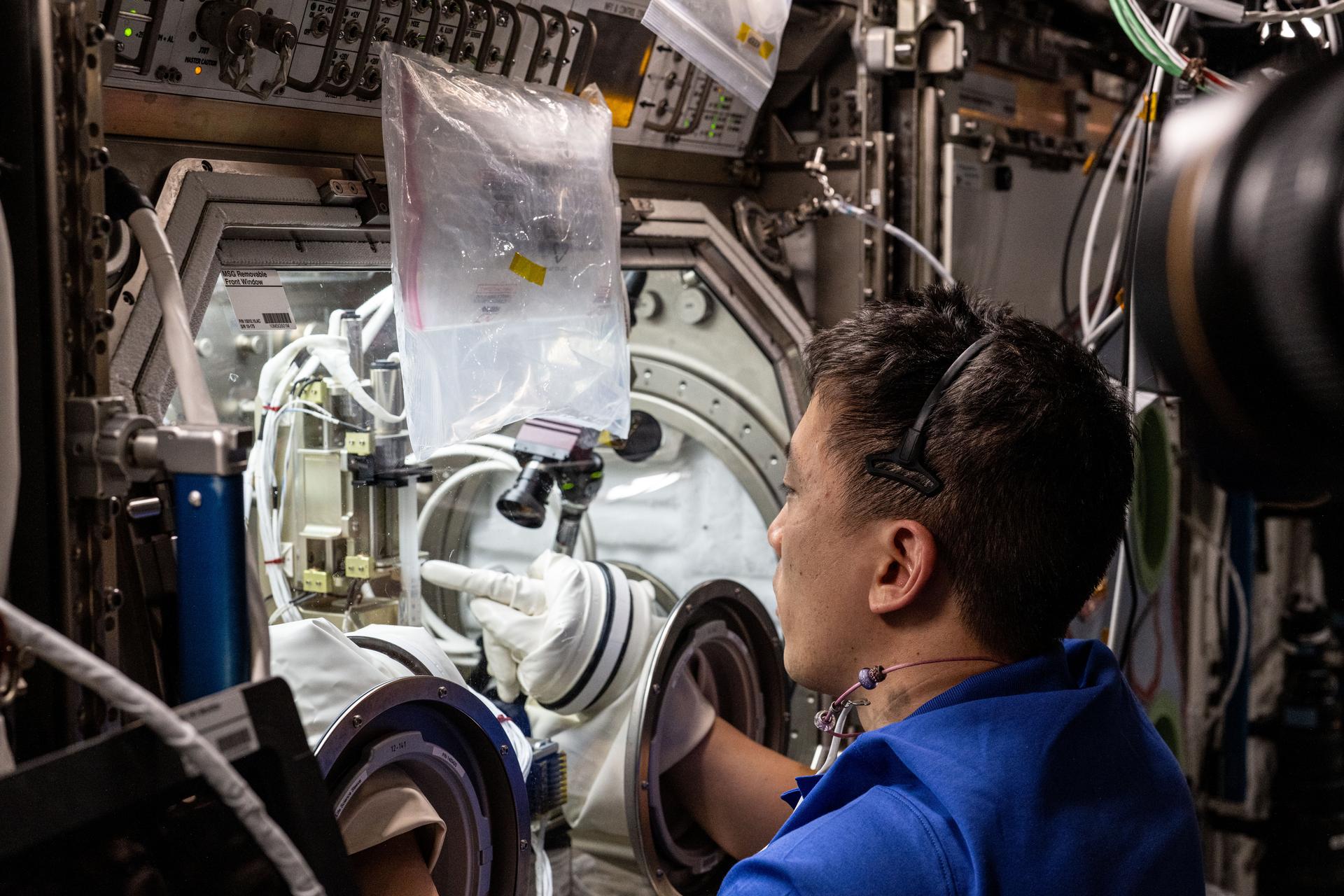
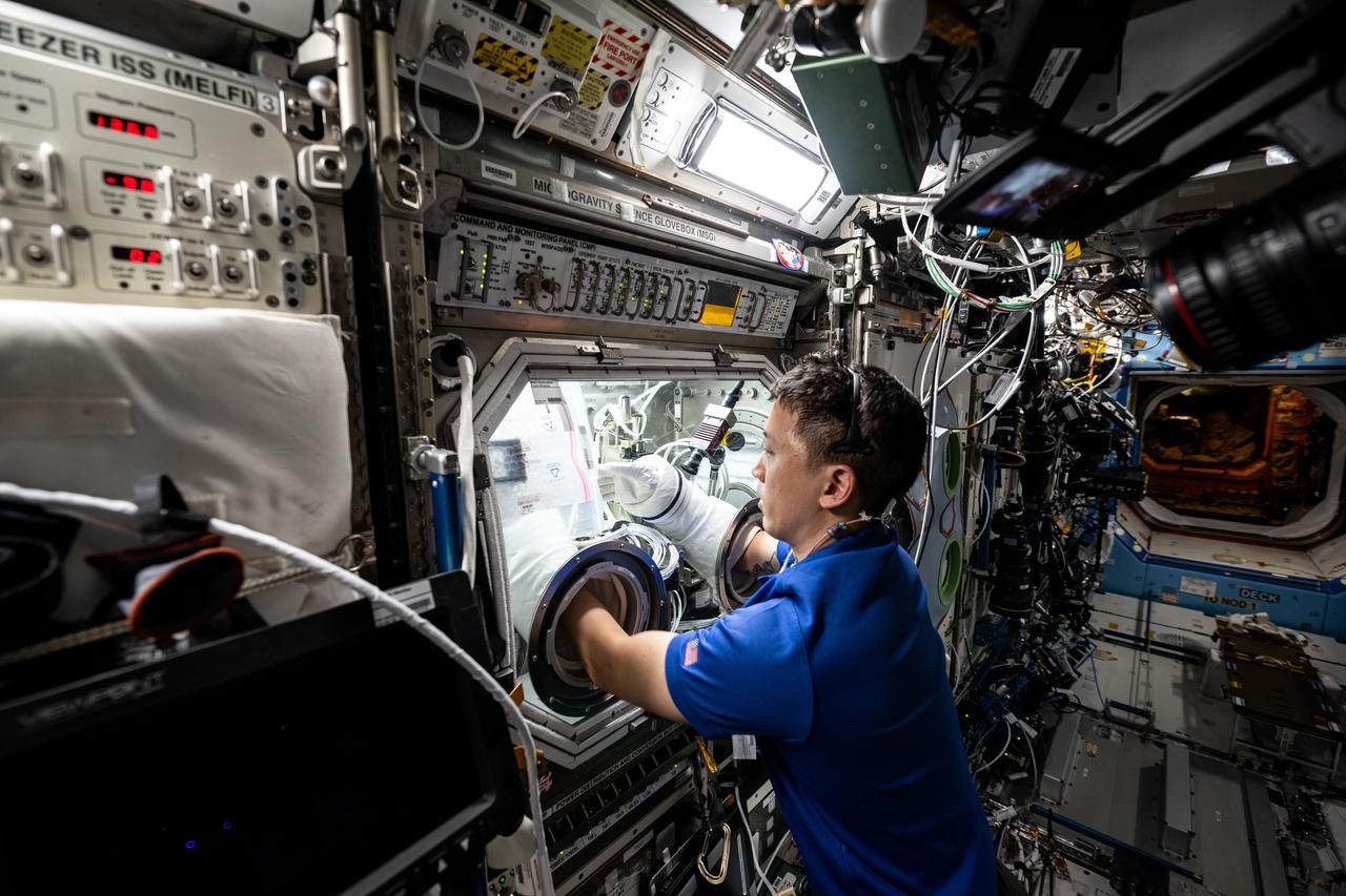
iss073e0177558 (June 12, 2025) -- NASA astronaut Jonny Kim works in the International Space Station’s Microgravity Science Glovebox on Ring Sheared Drop-IBP-2. This investigation studies the behavior of high-concentration protein fluids in microgravity using a special device that holds liquid protein solutions without containers, eliminating interference from interactions with container walls. Results could help advance manufacturing processes and 3D printing in space and for production of medicines, microelectronics, foods, and medical devices on Earth.
Today's VIS image shows a section of Labou Vallis. Labou Vallis is located south of Eumenides Dorsum and is 258 kilometers (160 miles) long. The 'tail' of the tear-dropped shaped island in the center of the channel points downstream, indicating the liquid flow was towards the top of this image. Orbit Number: 90200 Latitude: -7.83684 Longitude: 204.926 Instrument: VIS Captured: 2022-04-15 08:56 https://photojournal.jpl.nasa.gov/catalog/PIA25473
STS078-301-021 (20 June - 7 July 1996) --- Payload specialist Jean-Jacques Favier, representing the French Space Agency (CNES), holds up a test container to a Spacelab camera. The test involves the Bubble Drop Particle Unit (BDPU), which Favier is showing to ground controllers at the Marshall Space Flight Center (MSFC) in order to check the condition of the unit prior to heating in the BDPU facility. The test container holds experimental fluid and allows experiment observation through optical windows. BDPU contains three internal cameras that are used to continuously downlink BDPU activity so that behavior of the bubbles can be monitored. Astronaut Richard M. Linnehan, mission specialist, conducts biomedical testing in the background.

This Saturn V S-II (second) stage is being lifted into position for a test at the Vehicle Assembly Building at the Kennedy Space Center. When the Saturn V booster stage (S-IC) burned out and dropped away, power for the Saturn was provided by the 82-foot-long and 33-foot-diameter S-II stage. Developed by the Space Division of North American Aviation under the direction of the Marshall Space Flight Center, the stage utilized five J-2 engines, each producing 200,000 pounds of thrust. The engines used liquid oxygen and liquid hydrogen as propellants. The towering 363-foot Saturn V was a multi-stage, multi-engine launch vehicle standing taller than the Statue of Liberty. Altogether, the Saturn V engines produced as much power as 85 Hoover Dams.

iss073e0178587 (June 16, 2025) --- NASA astronaut and Expedition 73 Flight Engineer Nichole Ayers conducts research operations inside the Destiny laboratory module's Microgravity Science Glovebox aboard the International Space Station. Ayers swapped syringes containing protein samples and installed test cells inside the glovebox for the Ring-Sheared Drop Interfacial Bioprocessing of Pharmaceuticals investigation that explores using surface tension to contain liquids and study proteins without contacting solid walls. Results may benefit pharmaceutical manufacturing and 3D printing techniques on and off the Earth.
iss073e0248499 (June 25, 2025) --- NASA astronaut and Expedition 73 Flight Engineer Nichole Ayers conducts research operations inside the Destiny laboratory module's Microgravity Science Glovebox aboard the International Space Station. Ayers swapped syringes containing protein samples and installed test cells inside the glovebox for the Ring-Sheared Drop Interfacial Bioprocessing of Pharmaceuticals investigation that explores using surface tension to contain liquids and study proteins without contacting solid walls. Results may benefit pharmaceutical manufacturing and 3D printing techniques on and off the Earth.
iss073e0177791 (June 12, 2025) --- NASA astronaut and Expedition 73 Flight Engineer Jonny Kim conducts research operations inside the Destiny laboratory module's Microgravity Science Glovebox aboard the International Space Station. Kim swapped syringes containing protein samples and installed test cells inside the glovebox for the Ring-Sheared Drop Interfacial Bioprocessing of Pharmaceuticals investigation that explores using surface tension to contain liquids and study proteins without contacting solid walls. Results may benefit pharmaceutical manufacturing and 3D printing techniques on and off the Earth.
National Aeronautics and Space Administration (NASA) Lewis Research Center. Lewis researchers had been studying the behavior of liquid in microgravity for several years using ballistic rocket flights, aircraft flying series of parabolas, and in the 2.2-Second Drop Tower. It was easier to control experiments and repeat tests based on almost instantaneous test results in the Zero Gravity Research Facility than missiles or aircraft. It also more than doubled the microgravity time of the original drop tower. The experiments were enclosed in a large experiment package that was suspended inside the chamber. A vacuum was introduced to the chamber before the package was released. The test equipment allowed researchers to film and take measurements of the experiment as it was falling. The 2500‐pound package was slowed by special Styrofoam‐like pellets in a decelerator cart. An experiment, traveling 176 feet per second, was stopped in about 15 feet of deceleration material. The facility’s designers struggled to determine the correct type of deceleration pellets to use. For several years Lewis engineers tested various samples from manufacturers. The final selection was not made until the facility’s completion in May 1966, just before the facility made its public debut at the 1966 Inspection of the Center.
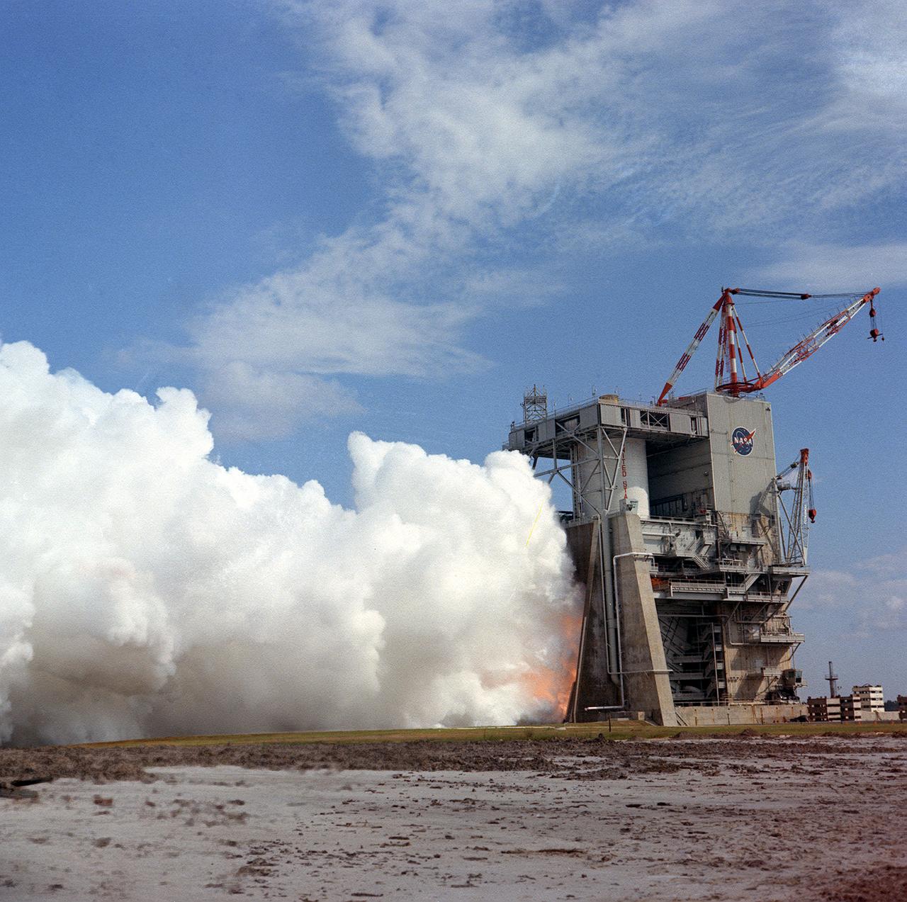
This photograph shows a test firing of the the Saturn V S-II (second) stage at the Mississippi Test Facility's (MTF) S-II test stand. When the Saturn V booster stage (S-IC) burns out and drops away, power for the Saturn will be provided by the 82-foot-long and 33-foot-diameter S-II stage. Developed by the Space Division of North American Aviation under the direction of the Marshall Space Flight Center, the stage utilized five J-2 engines, each producing 200,000 pounds of thrust. The engines used liquid oxygen and liquid hydrogen as propellants. Static test of ground test versions of the S-II stage were conducted at North American Aviation's Santa Susana, California test site. All flight stages were tested at the Mississippi Test Facility, Bay St. Louis, Mississippi. MTF was renamed to the National Space Technology Laboratory (NSTL) in 1974 and later to the Sternis Space Center in May 1988.
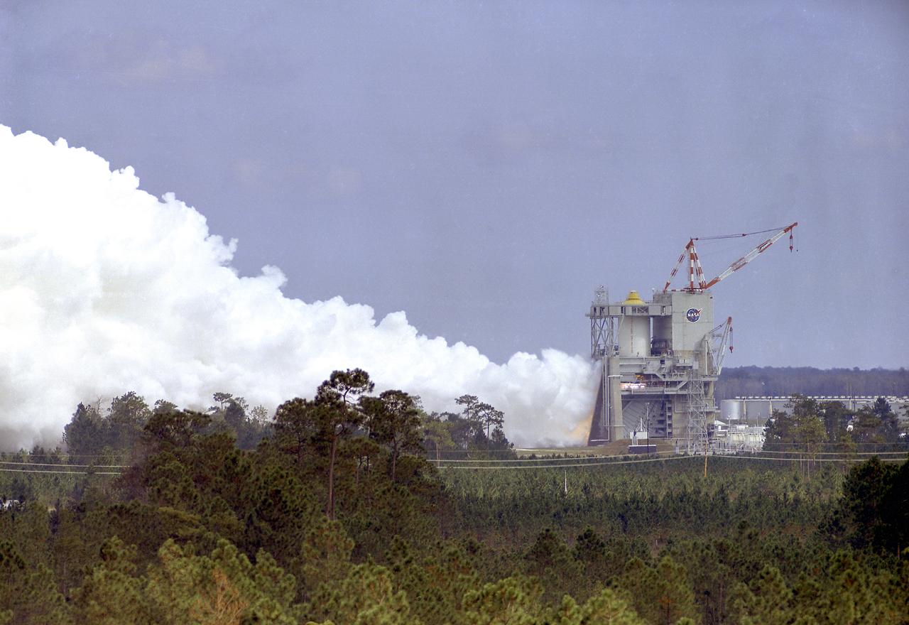
This photograph shows a test firing of the the Saturn V S-II (second) stage at the Mississippi Test Facility's (MTF) S-II test stand. When the Saturn V booster stage (S-IC) burns out and drops away, power for the Saturn will be provided by the 82-foot-long and 33-foot-diameter S-II stage. Developed by the Space Division of North American Aviation under the direction of the Marshall Space Flight Center, the stage utilized five J-2 engines, each producing 200,000 pounds of thrust. The engine used liquid oxygen and liquid hydrogen as its propellants. Static test of ground test versions of the S-II stage were conducted at North American Aviation's Santa Susana, California test site. All flight stages were tested at the Mississippi Test Facility, Bay St. Louis, Mississippi. The MTF was renamed to the National Space Technology Laboratory (NSTL) in 1974 and later to the Sternis Space Center (SSC) in May 1988.
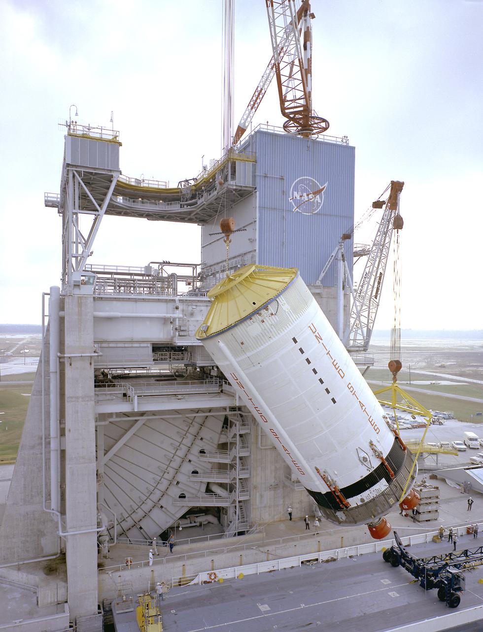
This photograph shows the Saturn V S-II (second) stage being hoisted at the S-II-A2 test stand at the Mississippi Test Facility (MTF). When the Saturn V booster stage (S-IC) burns out and drops away, power for the Saturn will be provided by the 82-foot-long and 33-foot-diameter S-II stage. Developed by the Space Division of North American Aviation under the direction of the Marshall Space Flight Center, the stage utilized five J-2 engines, each producing 200,000 pounds of thrust. The engines used liquid oxygen and liquid hydrogen as propellants. Static test of ground test versions of the S-II stage were conducted at North American Aviation's Santa Susana, California test site. All flight stages were tested at the Mississippi Test Facility, Bay St. Louis, Mississippi. MTF was renamed to the National Space Technology Laboratory (NSTL) in 1974 and later to the Sternis Space Center in May 1988.
This false color image contains several channel features. Towards the top of the image are several stream-lined islands, created by liquid flow eroding preexisting rock. The islands have a tear-drop shape, with the pointy end down stream from the rounded end. In this case the fluid flowed from the bottom right of the frame towards the upper left. Just below the center of the image is a larger, deeper channel. All these channel features merge into Ares Vallis, a huge outflow channel that empties into Chryse Planitia. The THEMIS VIS camera contains 5 filters. The data from different filters can be combined in multiple ways to create a false color image. These false color images may reveal subtle variations of the surface not easily identified in a single band image. Orbit Number: 61501 Latitude: 4.31188 Longitude: 343.17 Instrument: VIS Captured: 2015-10-25 18:03 https://photojournal.jpl.nasa.gov/catalog/PIA23066
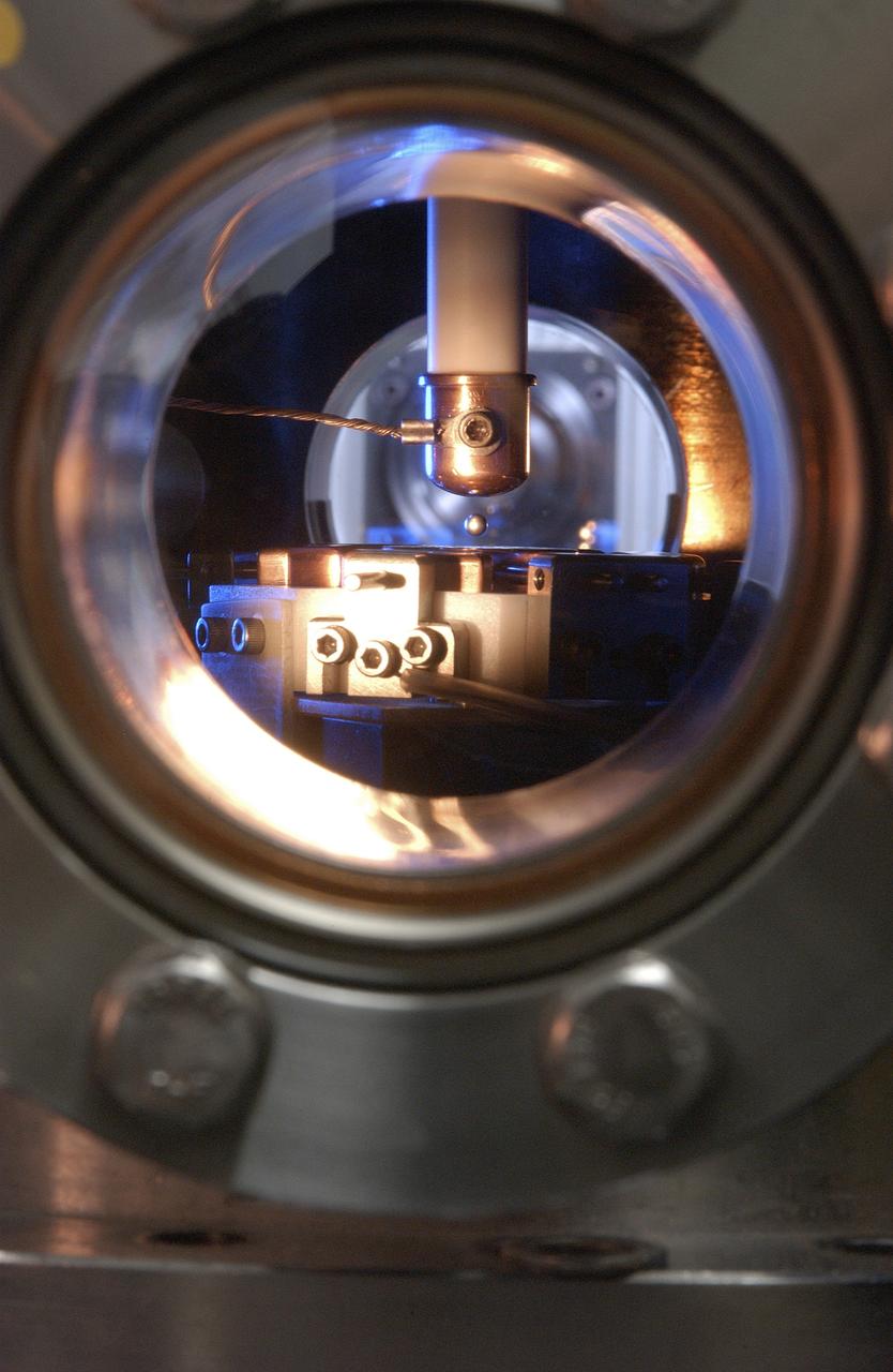
This Photo, which appeared on the July cover of `Physics Today', is of the Electrostatic Levitator (ESL) at NASA's Marshall Space Flight Center (MSFC). The ESL uses static electricity to suspend an object (about 3-4 mm in diameter) inside a vacuum chamber allowing scientists to record a wide range of physical properties without the sample contracting the container or any instruments, conditions that would alter the readings. Once inside the chamber, a laser heats the sample until it melts. The laser is then turned off and the sample cools, changing from a liquid drop to a solid sphere. In this particular shot, the ESL contains a solid metal sample of titanium-zirconium-nickel alloy. Since 1977, the ESL has been used at MSFC to study the characteristics of new metals, ceramics, and glass compounds. Materials created as a result of these tests include new optical materials, special metallic glasses, and spacecraft components.
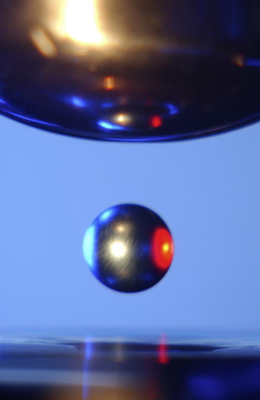
This is a close-up of a sample of titanium-zirconium-nickel alloy inside the Electrostatic Levitator (ESL) vacuum chamber at NASA's Marshall Space Flight Center (MSFC). The ESL uses static electricity to suspend an object (about 3-4 mm in diameter) inside a vacuum chamber allowing scientists to record a wide range of physical properties without the sample contracting the container or any instruments, conditions that would alter the readings. Once inside the chamber, a laser heats the sample until it melts. The laser is then turned off and the sample cools, changing from a liquid drop to a solid sphere. Since 1977, the ESL has been used at MSFC to study the characteristics of new metals, ceramics, and glass compounds. Materials created as a result of these tests include new optical materials, special metallic glasses, and spacecraft components.
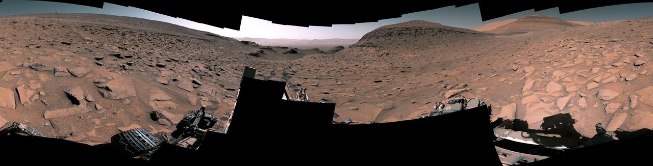
NASA's Curiosity Mars rover captured this 360-degree panorama at a site nicknamed "Ubajara" on April 30, 2023, the 3,815th Martian day, or sol, of the mission. Taken by the rover's Mastcam, this panorama was stitched together from 141 images after they were sent to Earth. Dark rover tracks recede into the distance in the center of the scene. Curiosity used the drill on the end of its robotic arm to take a sample from Ubajara, then dropped the pulverized rock into instruments within the rover's body. One of those instruments, called CheMin (Chemistry & Mineralogy), used X-ray diffraction to discover the presence of an iron carbonate mineral called siderite in samples from this site and two others: one above and one below Ubajara in a region enriched with salty minerals called sulfates. The discovery of siderite may help solve one of Mars' mysteries: There is strong evidence that liquid water coursed over the planet's surface billions of years ago, suggesting Mars had a thick, carbon-rich atmosphere rather than the wispy one it has today (a thicker carbon dioxide atmosphere is required to provide enough pressure and warmth for water to remain liquid on a planet's surface; otherwise, it rapidly vaporizes or freezes – which is the case on Mars today). That carbon dioxide and water should have reacted with Martian rocks to create carbonate minerals. However, when scientists study the planet with satellites that ample carbonate hasn't been apparent – even at Curiosity's site. It's possible that other minerals may be masking carbonate from satellite near-infrared analysis, particularly in sulfate-rich areas. If other such layers across Mars also contain hidden carbonates, the amount of stored carbon dioxide would be part of that needed in the ancient atmosphere to create conditions warm enough to support liquid water. The rest could be hidden in other deposits or have been lost to space over time. https://photojournal.jpl.nasa.gov/catalog/PIA26554
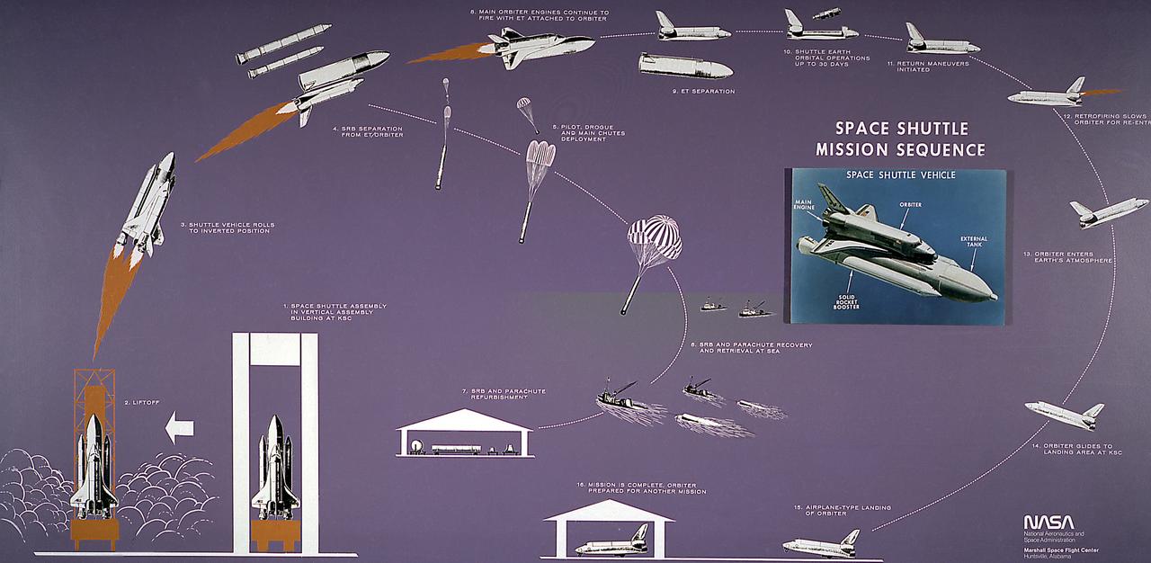
This diagram illustrates the Space Shuttle mission sequence. The Space Shuttle was approved as a national program in 1972 and developed through the 1970s. Part spacecraft and part aircraft, the Space Shuttle orbiter, the brain and the heart of the Space Transportation System (STS), required several technological advances, including thousands of insulating tiles able to stand the heat of reentry over the course of many missions, as well as sophisticated engines that could be used again and again without being thrown away. The airplane-like orbiter has three main engines, that burn liquid hydrogen and oxygen stored in the large external tank, the single largest structure in the Shuttle. Attached to the tank are two solid rocket boosters that provide the vehecile with most of the thrust needed for liftoff. Two minutes into the flight, the spent solids drop into the ocean to be recovered and refurbished for reuse, while the orbiter engines continue burning until approximately 8 minutes into the flight. After the mission is completed, the orbiter lands on a runway like an airplane.
A model of the new Aries I crew launch vehicle, for which NASA is designing, testing and evaluating hardware and related systems, is seen here on display at the Marshall Space Fight Center (MSFC), in Huntsville, Alabama. The Ares I crew launch vehicle is the rocket that will carry a new generation of space explorers into orbit. Under the goals of the Vision for Space Exploration, Ares I is a chief component of the cost-effective space transportation infrastructure being developed by NASA’s Constellation Program. These transportation systems will safely and reliably carry human explorers back to the moon, and then onward to Mars and other destinations in the solar system. The Ares I effort includes multiple project element teams at NASA centers and contract organizations around the nation, and is led by the Exploration Launch Projects Office at NASA’s MFSC. Together, these teams are developing vehicle hardware, evolving proven technologies, and testing components and systems. Their work builds on powerful, reliable space shuttle propulsion elements and nearly a half-century of NASA space flight experience and technological advances. Ares I is an inline, two-stage rocket configuration topped by the Crew Exploration Vehicle, its service module and a launch abort system. The launch vehicle’s first stage is a single, five-segment reusable solid rocket booster derived from the Space Shuttle Program’s reusable solid rocket motor that burns a specially formulated and shaped solid propellant called polybutadiene acrylonitrile (PBAN). The second or upper stage will be propelled by a J-2X main engine fueled with liquid oxygen and liquid hydrogen. In addition to its primary mission of carrying crews of four to six astronauts to Earth orbit, the launch vehicle’s 25-ton payload capacity might be used for delivering cargo to space, bringing resources and supplies to the International Space Station or dropping payloads off in orbit for retrieval and transport to exploration teams on the moon. Crew transportation to the space station is planned to begin no later than 2014. The first lunar excursion is scheduled for the 2020 timeframe.
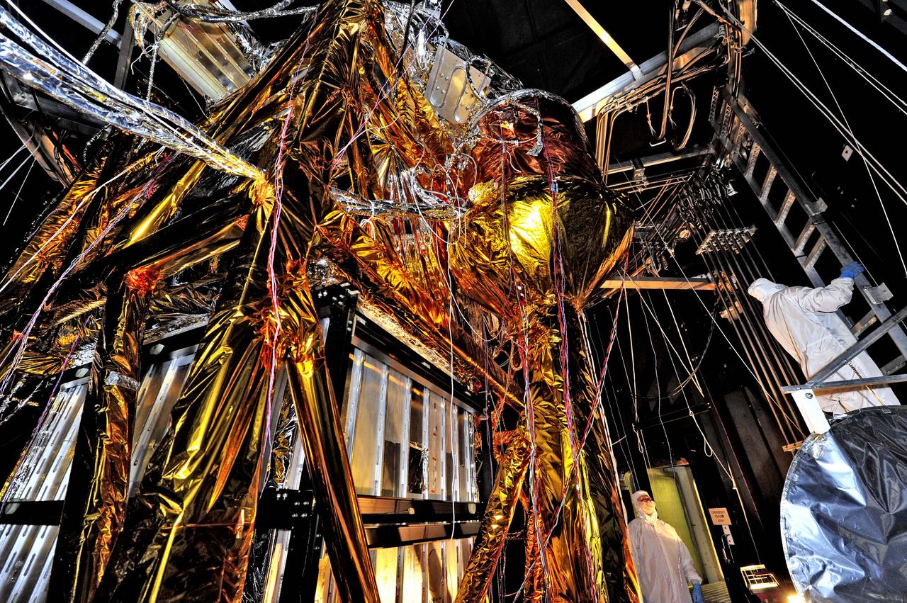
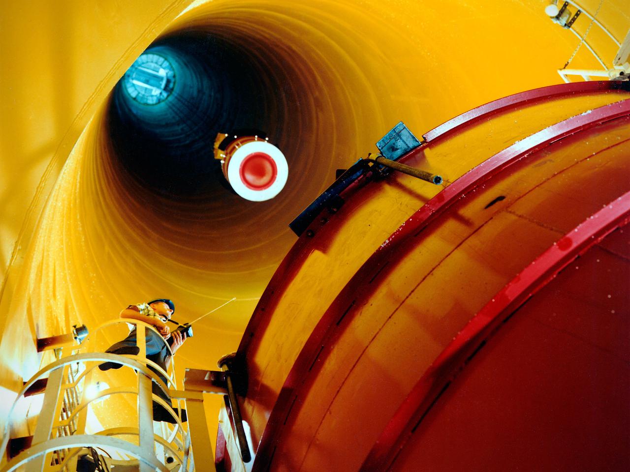
NASA image release August 23, 2012 What looks like a giant golden spider weaving a web of cables and cords, is actually ground support equipment, including the Optical Telescope Simulator (OSIM), for the James Webb Space Telescope. OSIM's job is to generate a beam of light just like the one that the real telescope optics will feed into the actual flight instruments. Because the real flight instruments will be used to test the real flight telescope, their alignment and performance first have to be verified by using the OSIM. Engineers are thoroughly checking out OSIM now in preparation for using it to test the flight science instruments later. This photo was taken from inside a large thermal-vacuum chamber called the Space Environment Simulator (SES), at NASA's Goddard Space Flight Center in Greenbelt, Md. Engineers have blanketed the structure of the OSIM with special insulating material to help control its temperature while it goes into the deep freeze testing that mimics the chill of space that Webb will ultimately experience in its operational orbit over 1 million miles from Earth. The golden-colored thermal blankets are made of aluminized kapton, a polymer film that remains stable over a wide range of temperatures. The structure that looks like a silver and black cube underneath the "spider" is a set of cold panels that surround OSIM's optics. During testing, OSIM's temperature will drop to 100 Kelvin (-280 F or -173 C) as liquid nitrogen flows through tubes welded to the chamber walls and through tubes along the silver panels surrounding OSIM's optics. These cold panels will keep the OSIM optics very cold, but the parts covered by the aluminized kapton blankets will stay warm. "Some blankets have silver facing out and gold facing in, or inverted, or silver on both sides, etc.," says Erin Wilson, a Goddard engineer. "Depending on which side of the blanket your hardware is looking at, the blankets can help it get colder or stay warmer, in an environmental test." Another reason for thermal blankets is to shield the cold OSIM optics from unwanted stray infrared light. When the OSIM is pointing its calibrated light beam at Webb's science instruments, engineers don't want any stray infrared light, such as "warm photons" from warm structures, leaking into the instruments' field of view. Too much of this stray light would raise the background too much for the instruments to "see" light from the OSIM—it would be like trying to photograph a lightning bug flying in front of car headlights. To get OSIM's optics cold, the inside of the chamber has to get cold, and to do that, all the air has to be pumped out to create a vacuum. Then liquid nitrogen has to be run though the plumbing along the inner walls of the chamber. Wilson notes that's why the blankets have to have vents in them: "That way, the air between all the layers can be evacuated as the chamber pressure drops, otherwise the blankets could pop," says Wilson. The most powerful space telescope ever built, Webb is the successor to NASA's Hubble Space Telescope. Webb's four instruments will reveal how the universe evolved from the Big Bang to the formation of our solar system. Webb is a joint project of NASA, the European Space Agency and the Canadian Space Agency. Credit: NASA/GSFC/Chris Gunn <b><a href="http://www.nasa.gov/audience/formedia/features/MP_Photo_Guidelines.html" rel="nofollow">NASA image use policy.</a></b> <b><a href="http://www.nasa.gov/centers/goddard/home/index.html" rel="nofollow">NASA Goddard Space Flight Center</a></b> enables NASA’s mission through four scientific endeavors: Earth Science, Heliophysics, Solar System Exploration, and Astrophysics. Goddard plays a leading role in NASA’s accomplishments by contributing compelling scientific knowledge to advance the Agency’s mission. <b>Follow us on <a href="http://twitter.com/NASA_GoddardPix" rel="nofollow">Twitter</a></b> <b>Like us on <a href="http://www.facebook.com/pages/Greenbelt-MD/NASA-Goddard/395013845897?ref=tsd" rel="nofollow">Facebook</a></b> <b>Find us on <a href="http://instagrid.me/nasagoddard/?vm=grid" rel="nofollow">Instagram</a></b>