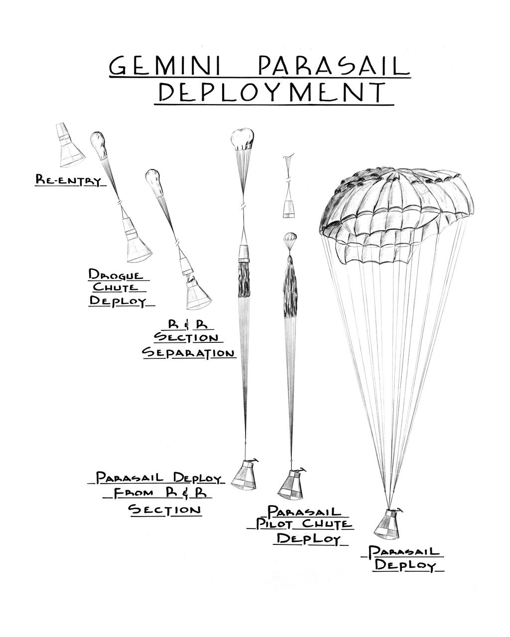
S63-12019 (1963) --- Artist concept for Gemini parasail deployment showing re-entry, drogue chute deployment, and stages of parasail deployment.
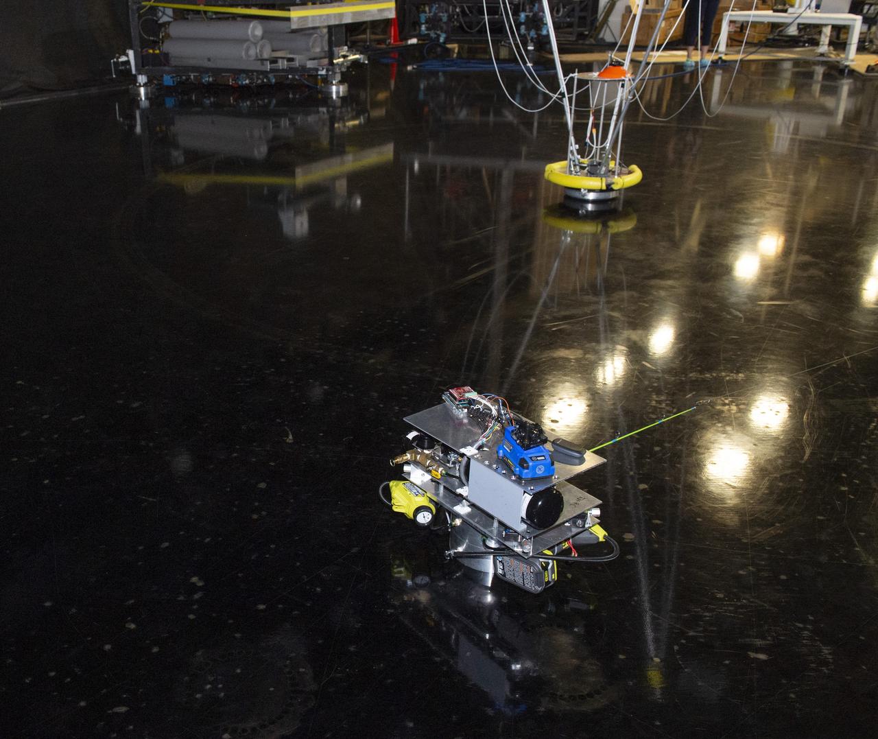
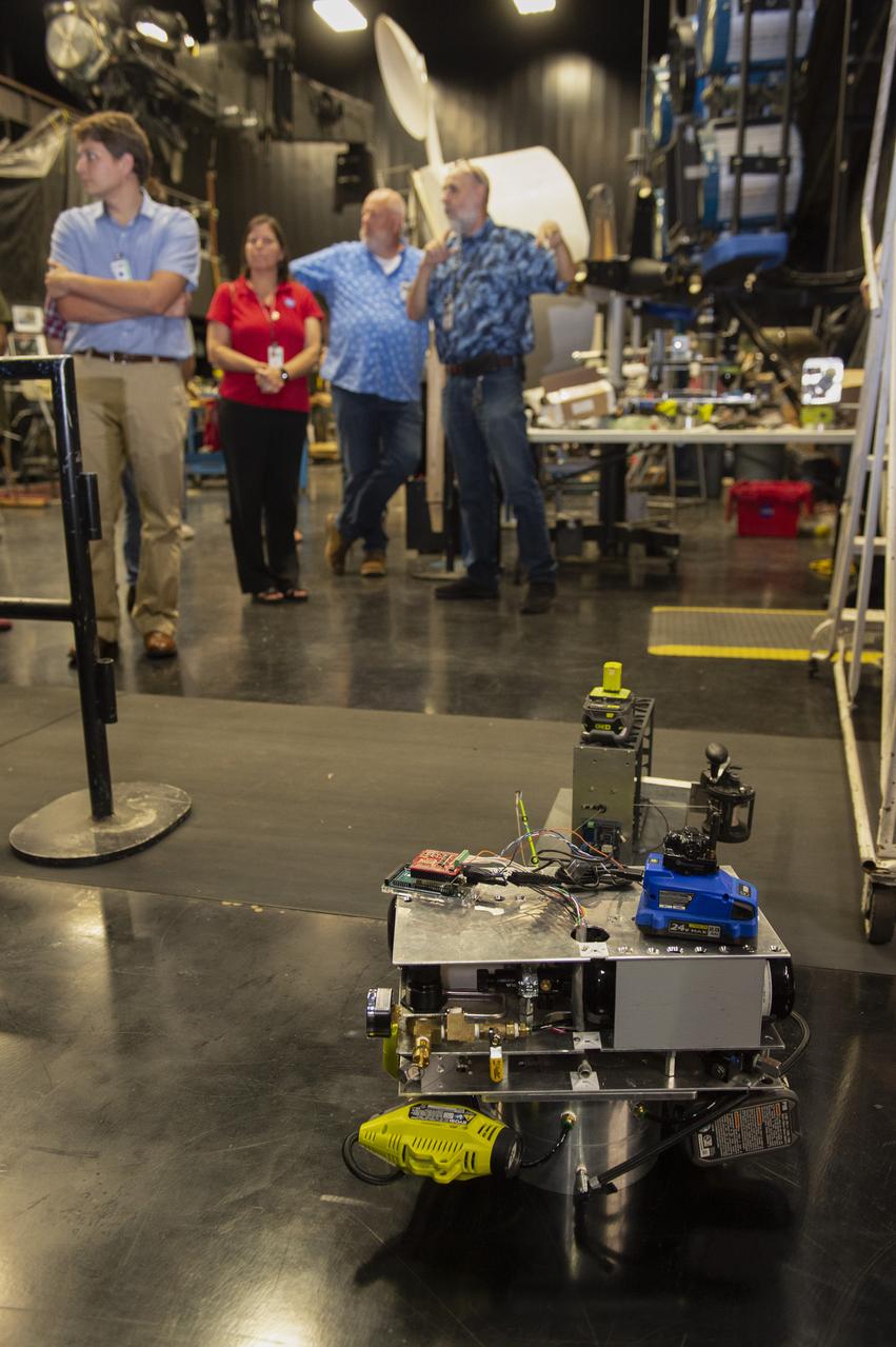
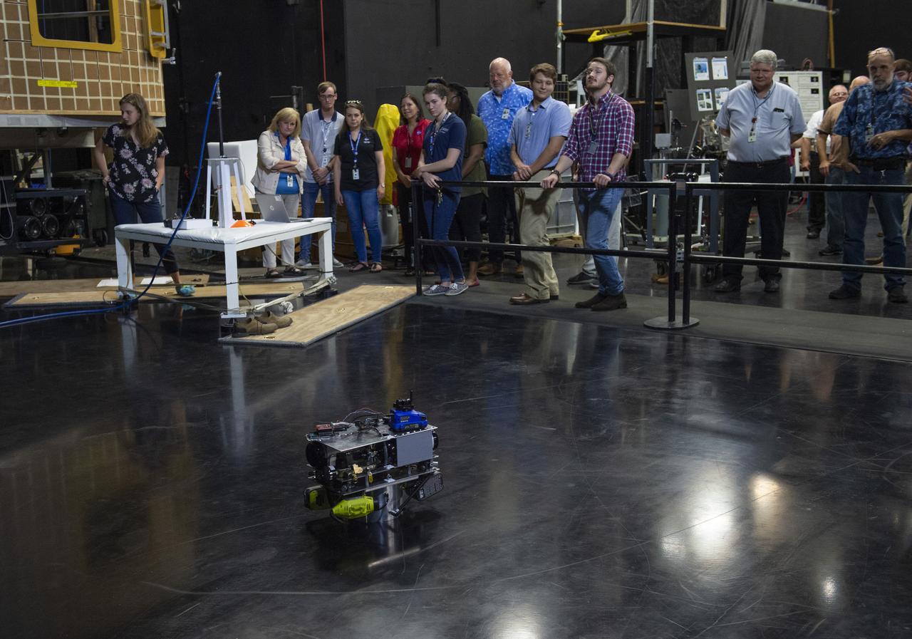
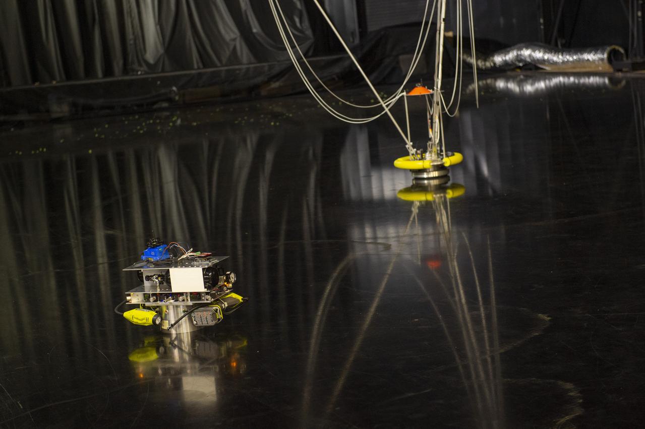
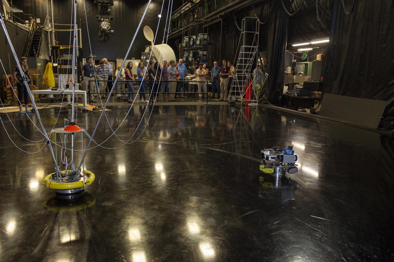
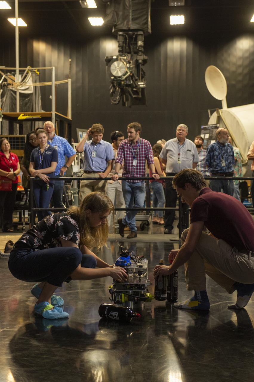
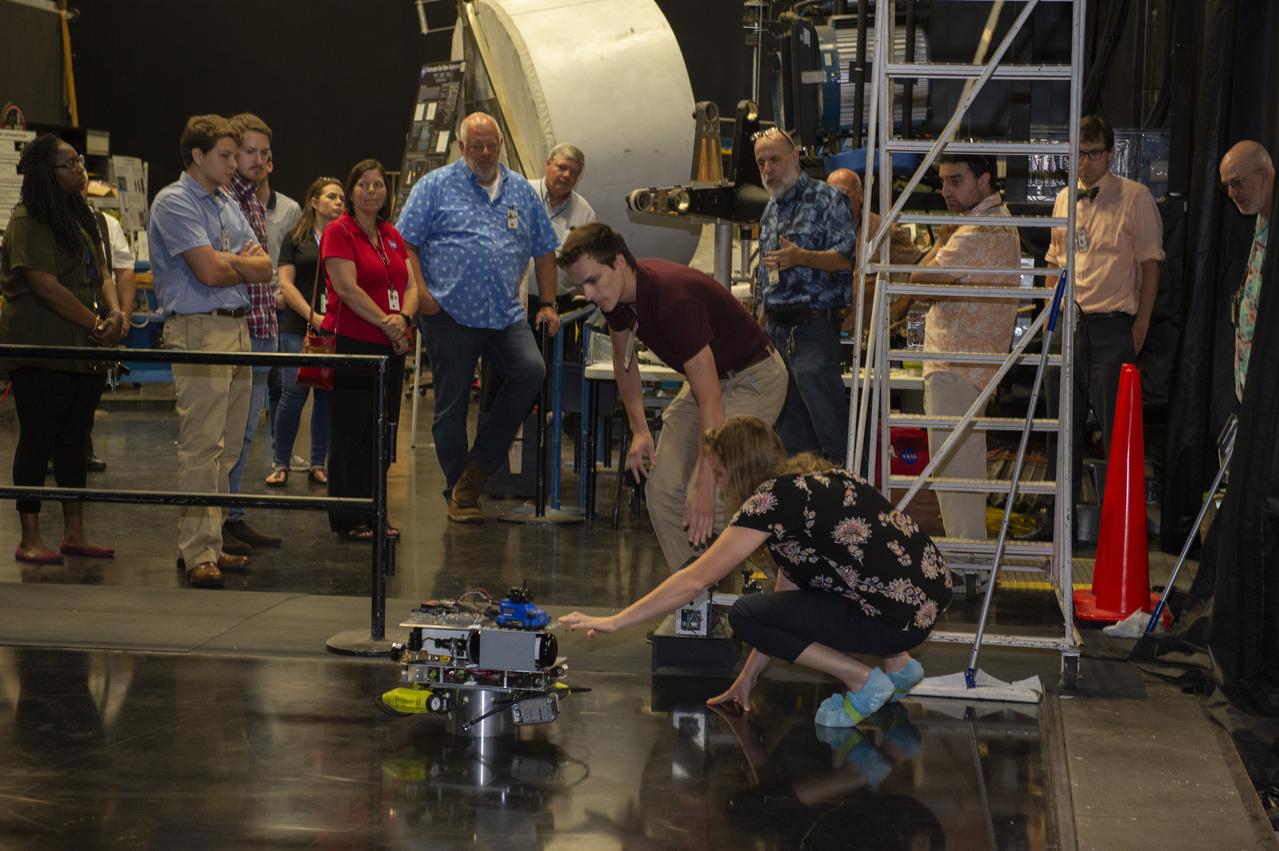
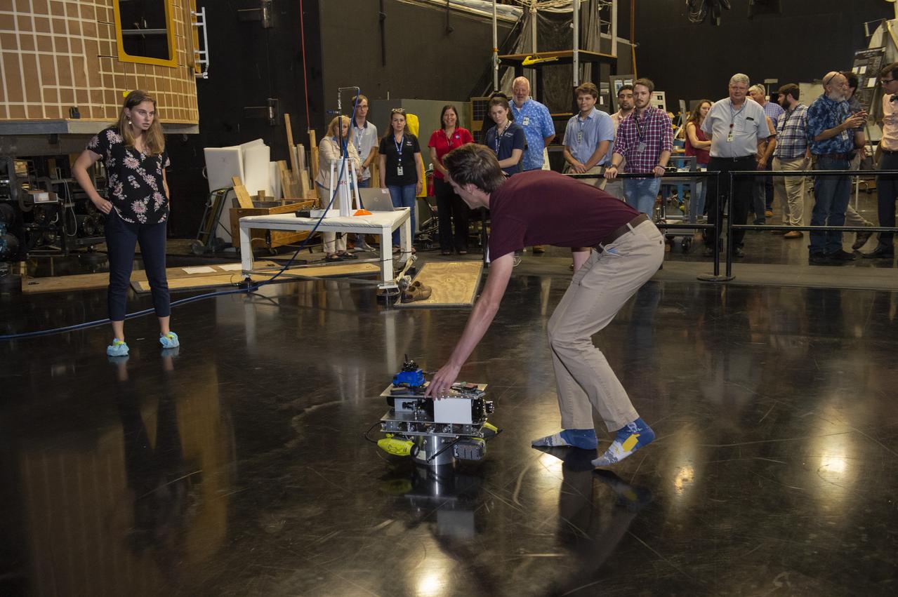
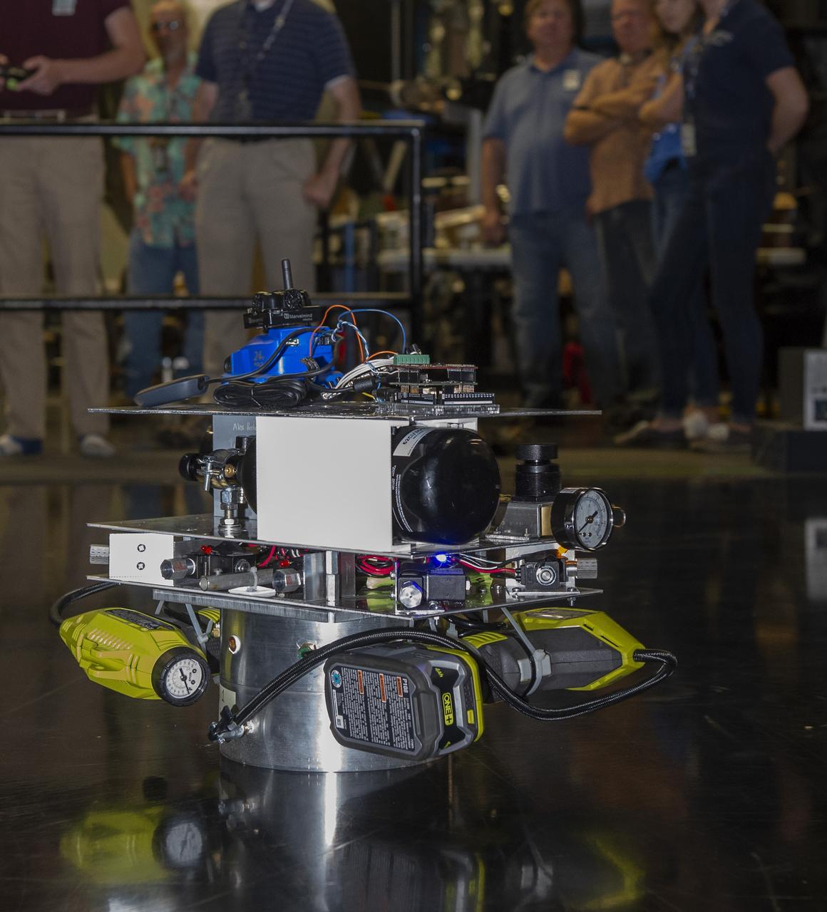
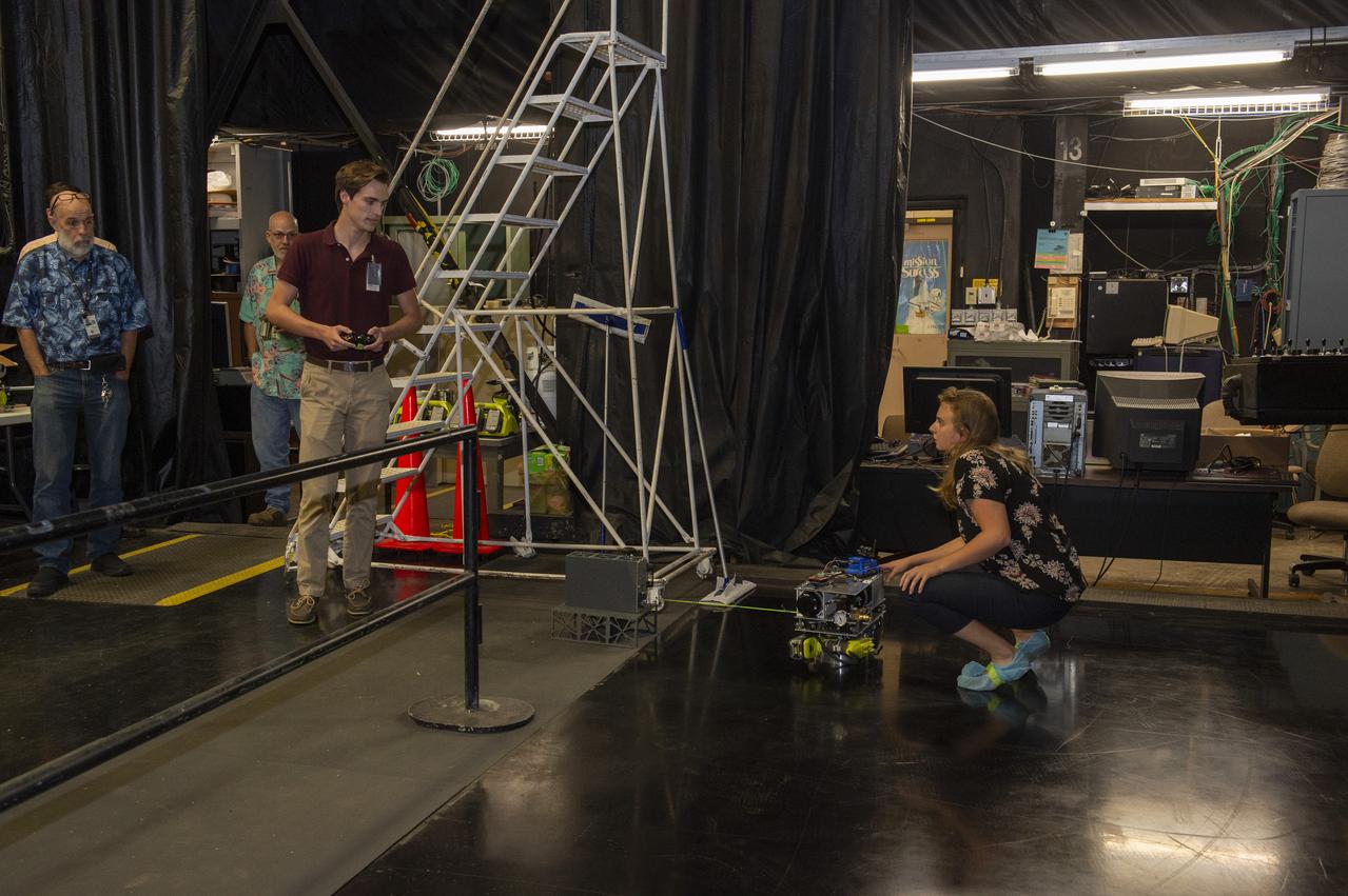
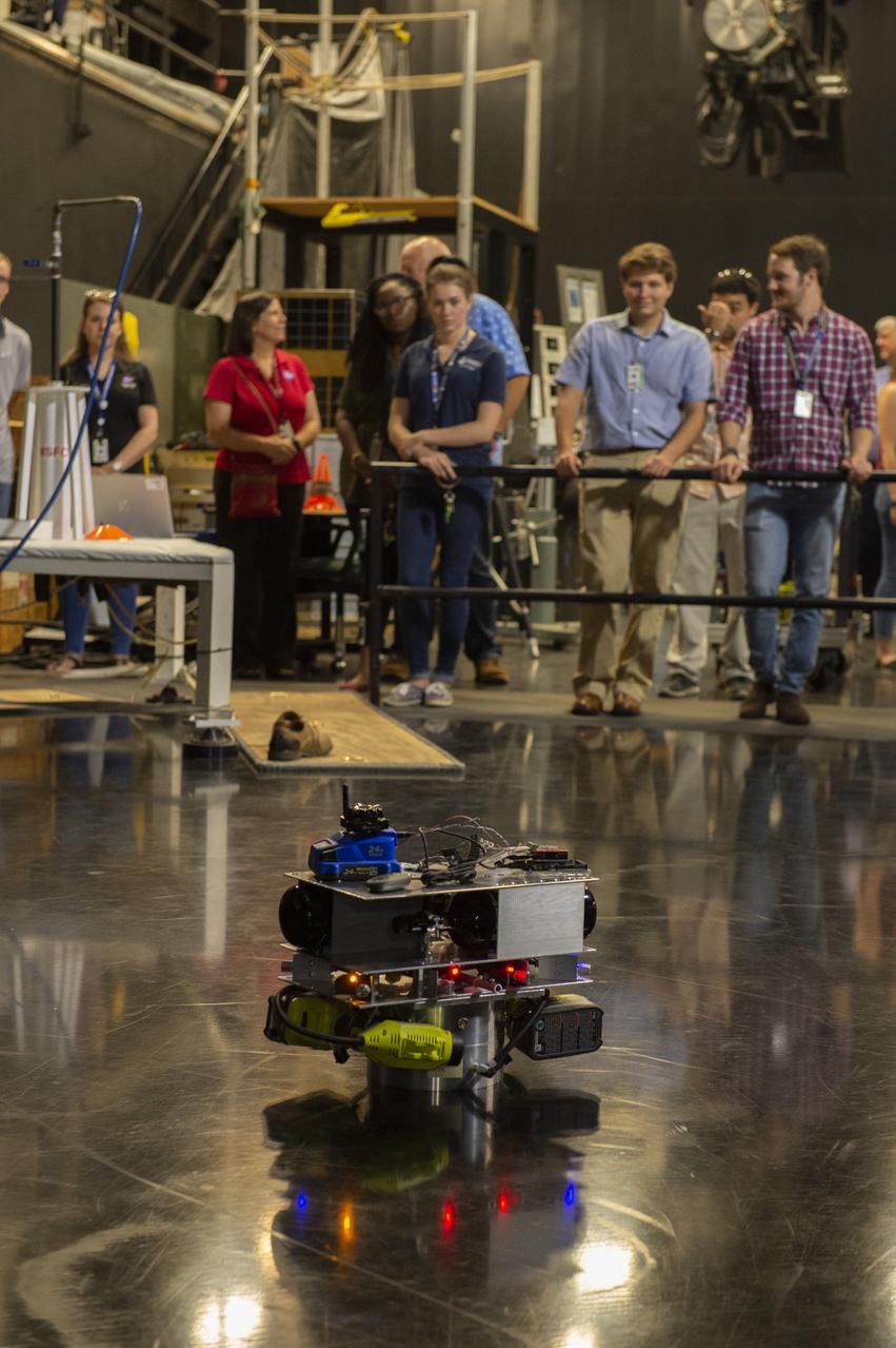
PATHWAYS INTERN ALEXANDRA BOEHM, AND JACOBS INTERN, PEYTON NELSON DEMONSTRATE STEERABLE AIR BEARING TETHER DEPLOYMENT SYSTEM TO MSFC SENIOR MANAGEMENT. ALSO WORKING ON THE PROJECT BUT NOT PICTURED WERE SUMMER INTERN ALI BERTELSMAN, PATHWAYS INTERN ANNA SHIPMAN, AND JACOBS FULL-TIME EMPLOYEE BRANDON MOORE.
PATHWAYS INTERN ALEXANDRA BOEHM, AND JACOBS INTERN, PEYTON NELSON DEMONSTRATE STEERABLE AIR BEARING TETHER DEPLOYMENT SYSTEM TO MSFC SENIOR MANAGEMENT. ALSO WORKING ON THE PROJECT BUT NOT PICTURED WERE SUMMER INTERN ALI BERTELSMAN, PATHWAYS INTERN ANNA SHIPMAN, AND JACOBS FULL-TIME EMPLOYEE BRANDON MOORE.
PATHWAYS INTERN ALEXANDRA BOEHM, AND JACOBS INTERN, PEYTON NELSON DEMONSTRATE STEERABLE AIR BEARING TETHER DEPLOYMENT SYSTEM TO MSFC SENIOR MANAGEMENT. ALSO WORKING ON THE PROJECT BUT NOT PICTURED WERE SUMMER INTERN ALI BERTELSMAN, PATHWAYS INTERN ANNA SHIPMAN, AND JACOBS FULL-TIME EMPLOYEE BRANDON MOORE.
PATHWAYS INTERN ALEXANDRA BOEHM, AND JACOBS INTERN, PEYTON NELSON DEMONSTRATE STEERABLE AIR BEARING TETHER DEPLOYMENT SYSTEM TO MSFC SENIOR MANAGEMENT. ALSO WORKING ON THE PROJECT BUT NOT PICTURED WERE SUMMER INTERN ALI BERTELSMAN, PATHWAYS INTERN ANNA SHIPMAN, AND JACOBS FULL-TIME EMPLOYEE BRANDON MOORE.
PATHWAYS INTERN ALEXANDRA BOEHM, AND JACOBS INTERN, PEYTON NELSON DEMONSTRATE STEERABLE AIR BEARING TETHER DEPLOYMENT SYSTEM TO MSFC SENIOR MANAGEMENT. ALSO WORKING ON THE PROJECT BUT NOT PICTURED WERE SUMMER INTERN ALI BERTELSMAN, PATHWAYS INTERN ANNA SHIPMAN, AND JACOBS FULL-TIME EMPLOYEE BRANDON MOORE.
PATHWAYS INTERN ALEXANDRA BOEHM, AND JACOBS INTERN, PEYTON NELSON DEMONSTRATE STEERABLE AIR BEARING TETHER DEPLOYMENT SYSTEM TO MSFC SENIOR MANAGEMENT. ALSO WORKING ON THE PROJECT BUT NOT PICTURED WERE SUMMER INTERN ALI BERTELSMAN, PATHWAYS INTERN ANNA SHIPMAN, AND JACOBS FULL-TIME EMPLOYEE BRANDON MOORE.
PATHWAYS INTERN ALEXANDRA BOEHM, AND JACOBS INTERN, PEYTON NELSON DEMONSTRATE STEERABLE AIR BEARING TETHER DEPLOYMENT SYSTEM TO MSFC SENIOR MANAGEMENT. ALSO WORKING ON THE PROJECT BUT NOT PICTURED WERE SUMMER INTERN ALI BERTELSMAN, PATHWAYS INTERN ANNA SHIPMAN, AND JACOBS FULL-TIME EMPLOYEE BRANDON MOORE.
PATHWAYS INTERN ALEXANDRA BOEHM, AND JACOBS INTERN, PEYTON NELSON DEMONSTRATE STEERABLE AIR BEARING TETHER DEPLOYMENT SYSTEM TO MSFC SENIOR MANAGEMENT. ALSO WORKING ON THE PROJECT BUT NOT PICTURED WERE SUMMER INTERN ALI BERTELSMAN, PATHWAYS INTERN ANNA SHIPMAN, AND JACOBS FULL-TIME EMPLOYEE BRANDON MOORE.

PATHWAYS INTERN ALEXANDRA BOEHM, AND JACOBS INTERN, PEYTON NELSON DEMONSTRATE STEERABLE AIR BEARING TETHER DEPLOYMENT SYSTEM TO MSFC SENIOR MANAGEMENT. ALSO WORKING ON THE PROJECT BUT NOT PICTURED WERE SUMMER INTERN ALI BERTELSMAN, PATHWAYS INTERN ANNA SHIPMAN, AND JACOBS FULL-TIME EMPLOYEE BRANDON MOORE.
PATHWAYS INTERN ALEXANDRA BOEHM, AND JACOBS INTERN, PEYTON NELSON DEMONSTRATE STEERABLE AIR BEARING TETHER DEPLOYMENT SYSTEM TO MSFC SENIOR MANAGEMENT. ALSO WORKING ON THE PROJECT BUT NOT PICTURED WERE SUMMER INTERN ALI BERTELSMAN, PATHWAYS INTERN ANNA SHIPMAN, AND JACOBS FULL-TIME EMPLOYEE BRANDON MOORE.
PATHWAYS INTERN ALEXANDRA BOEHM, AND JACOBS INTERN, PEYTON NELSON DEMONSTRATE STEERABLE AIR BEARING TETHER DEPLOYMENT SYSTEM TO MSFC SENIOR MANAGEMENT. ALSO WORKING ON THE PROJECT BUT NOT PICTURED WERE SUMMER INTERN ALI BERTELSMAN, PATHWAYS INTERN ANNA SHIPMAN, AND JACOBS FULL-TIME EMPLOYEE BRANDON MOORE.
PATHWAYS INTERN ALEXANDRA BOEHM, AND JACOBS INTERN, PEYTON NELSON DEMONSTRATE STEERABLE AIR BEARING TETHER DEPLOYMENT SYSTEM TO MSFC SENIOR MANAGEMENT. ALSO WORKING ON THE PROJECT BUT NOT PICTURED WERE SUMMER INTERN ALI BERTELSMAN, PATHWAYS INTERN ANNA SHIPMAN, AND JACOBS FULL-TIME EMPLOYEE BRANDON MOORE.
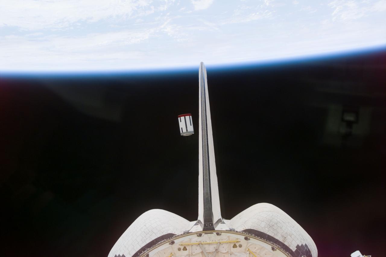
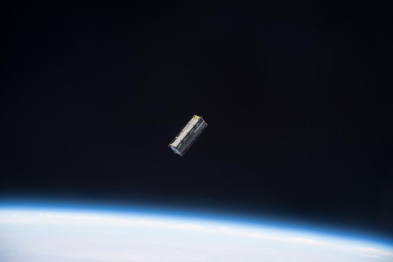
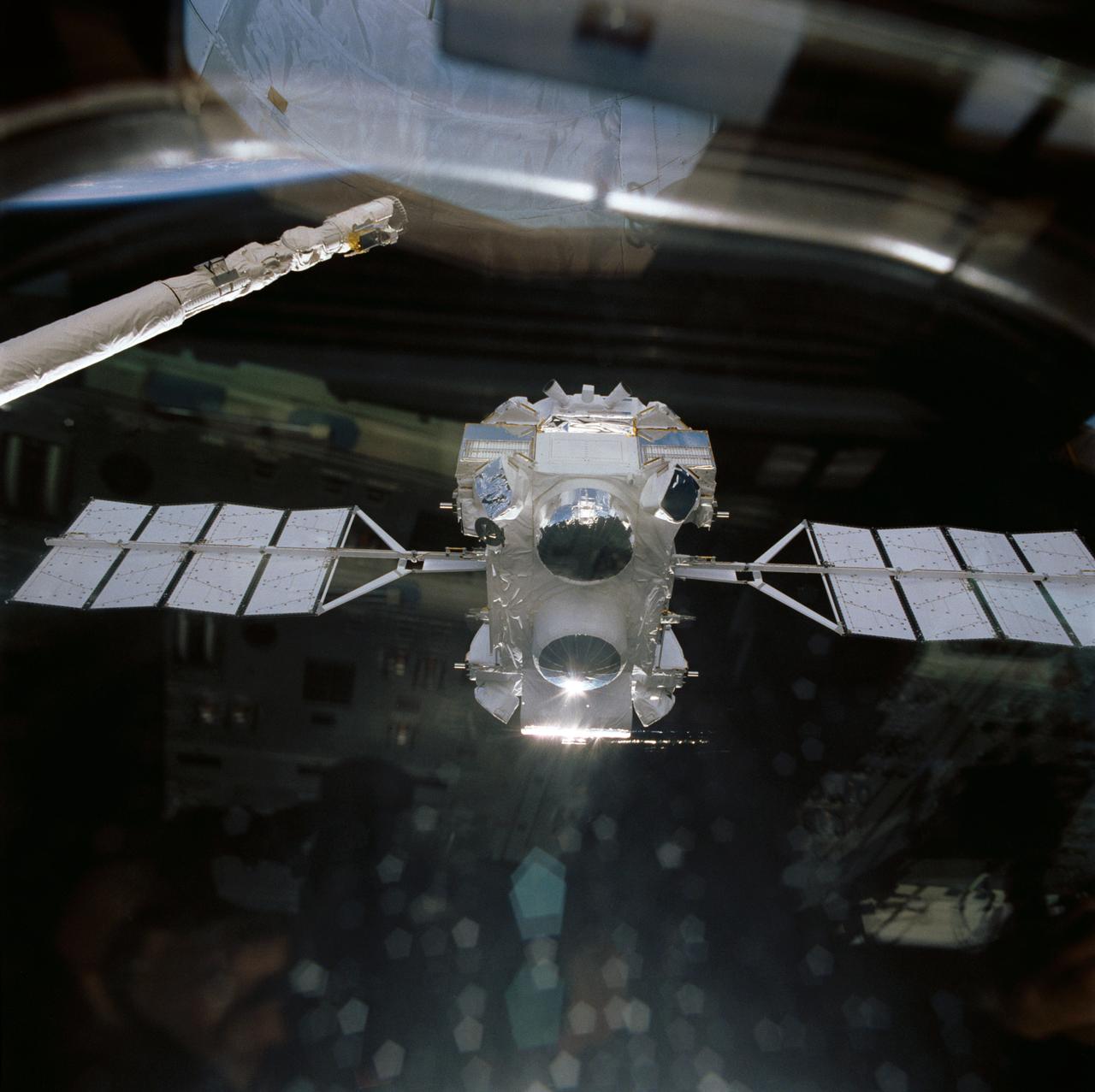
S77-E-5068 (22 May 1996) --- The Satellite Test Unit (STU), part of the Passive Aerodynamically Stabilized Magnetically Damped Satellite (PAMS) is seen moments after its ejection from the cargo bay of the Space Shuttle Endeavour. The scene was photographed with an Electronic Still Camera (ESC) onboard Endeavour's crew cabin during the deployment. The six-member crew will continue operations (tracking, rendezvousing and station-keeping) with PAMS-STU periodically throughout the remainder of the mission.
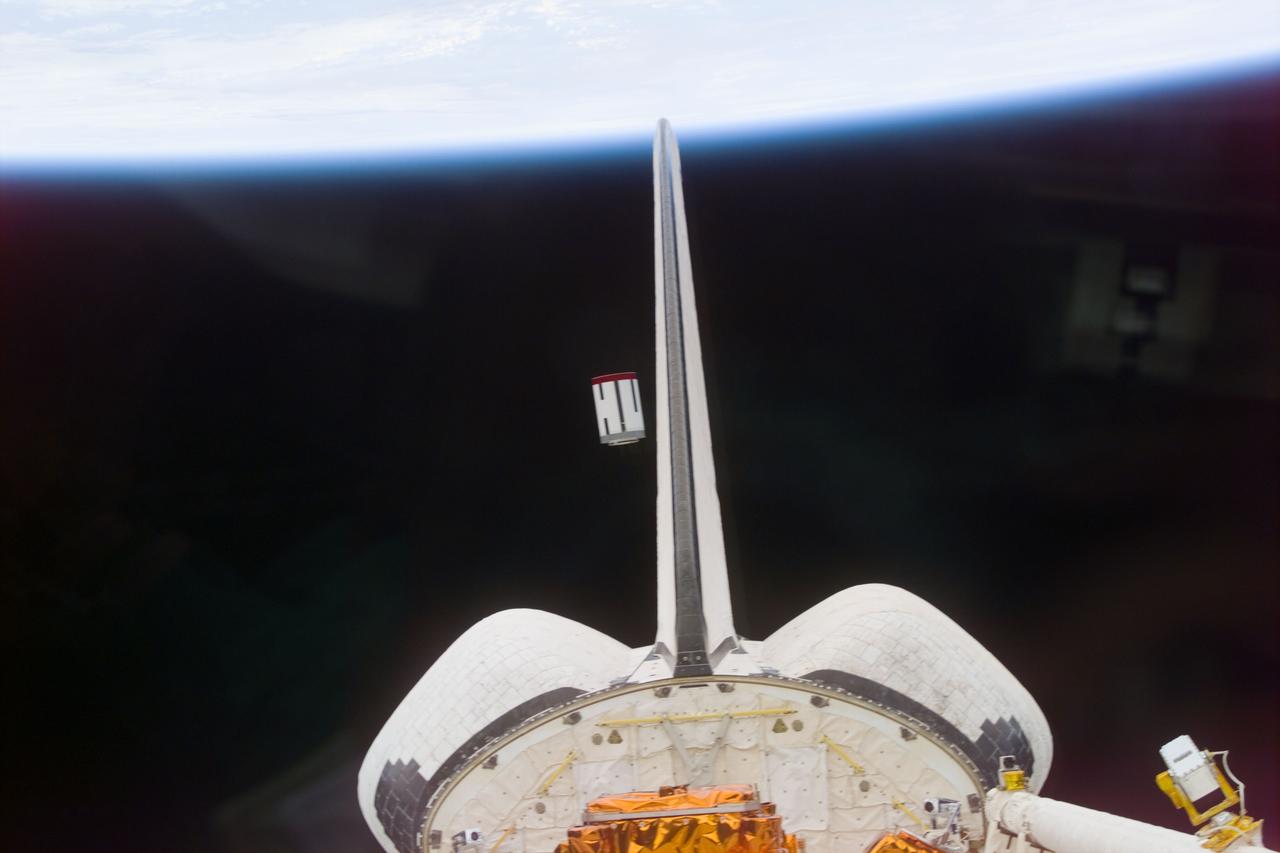
S77-E-5067 (22 May 1996) --- The Satellite Test Unit (STU), part of the Passive Aerodynamically Stabilized Magnetically Damped Satellite (PAMS) is seen moments after its ejection from the cargo bay of the Space Shuttle Endeavour. The scene was photographed with an Electronic Still Camera (ESC) onboard Endeavour's crew cabin during the deployment. The six-member crew will continue operations (tracking, rendezvousing and station-keeping) with PAMS-STU periodically throughout the remainder of the mission.
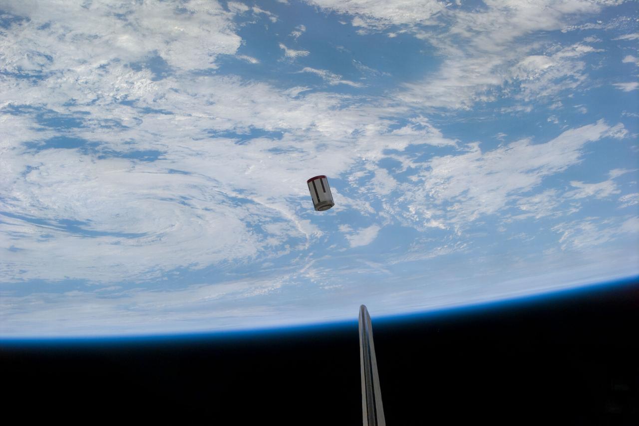
S77-E-5069 (22 May 1996) --- The Satellite Test Unit (STU), part of the Passive Aerodynamically Stabilized Magnetically Damped Satellite (PAMS) is seen moments after its ejection from the cargo bay of the Space Shuttle Endeavour. The scene was photographed with an Electronic Still Camera (ESC) onboard Endeavour's crew cabin during the deployment. The six-member crew will continue operations (tracking, rendezvousing and station-keeping) with PAMS-STU periodically throughout the remainder of the mission.
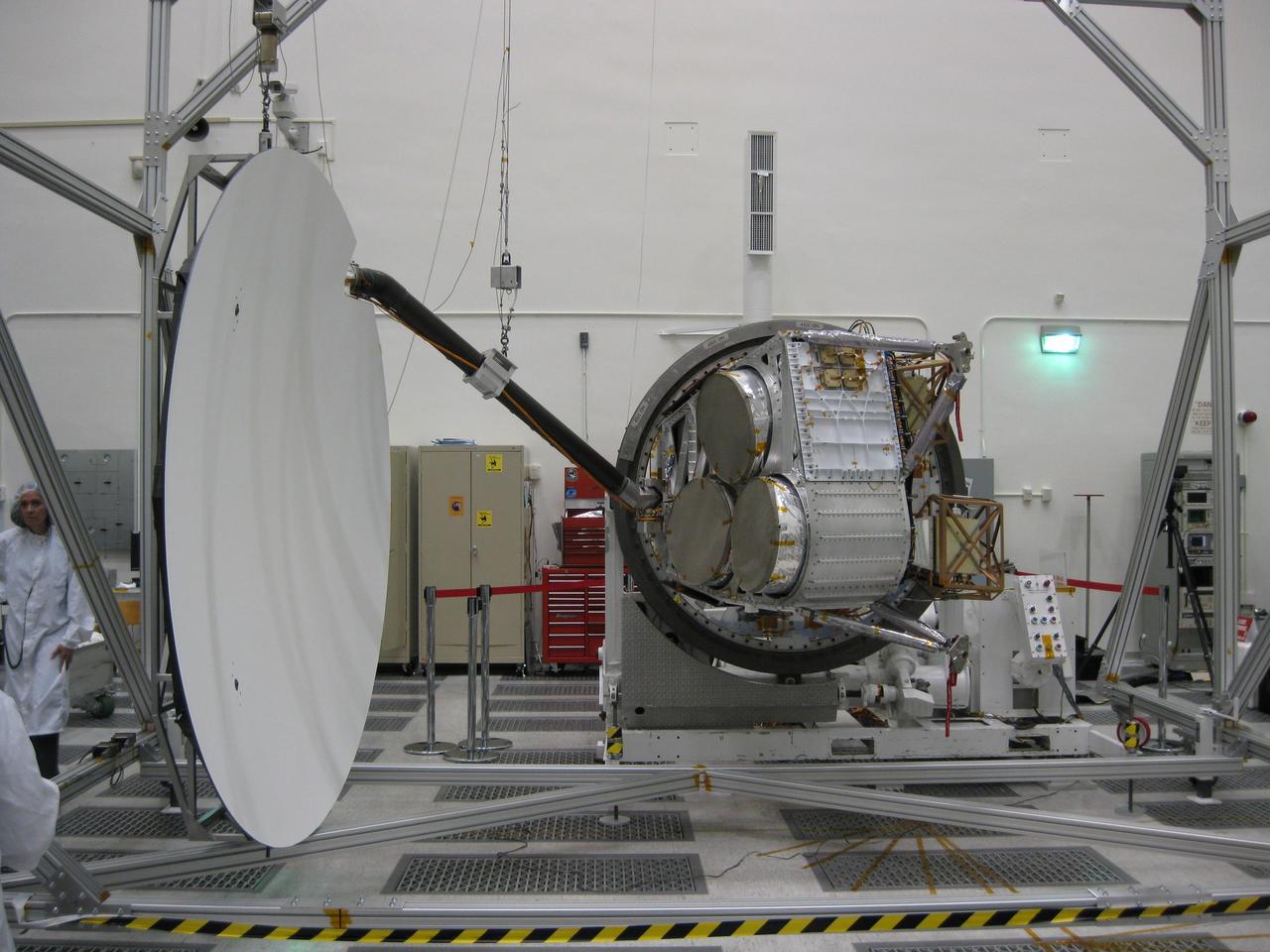
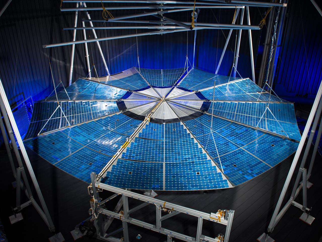
Aquarius reflector deployment is tested in the clean room at NASA Jet Propulsion Laboratory in Pasadena, Calif.
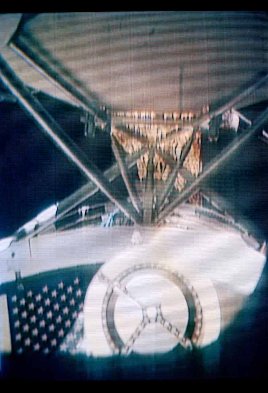
S73-26773 (26 May 1973) --- The deployment of the ?parasol? solar shield, a sunshade to help cool the overheated Orbital Workshop of the Skylab 1 space station cluster in Earth orbit, can be seen in the reproduction taken from a color television transmission made by a TV camera aboard the space station. The camera is in the Command Module; and the view is looking through the truss of the Apollo Telescope Mount. The sunshade is only partially deployed in this picture. The solar shield was pushed up through the OWS solar scientific airlock. The canopy of the ?parasol? measures 24 feet by 22 feet. Photo credit: NASA
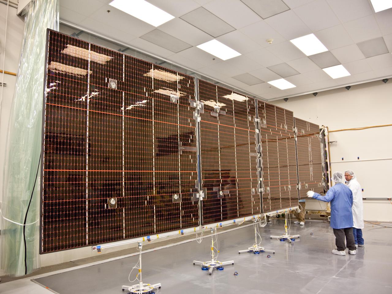
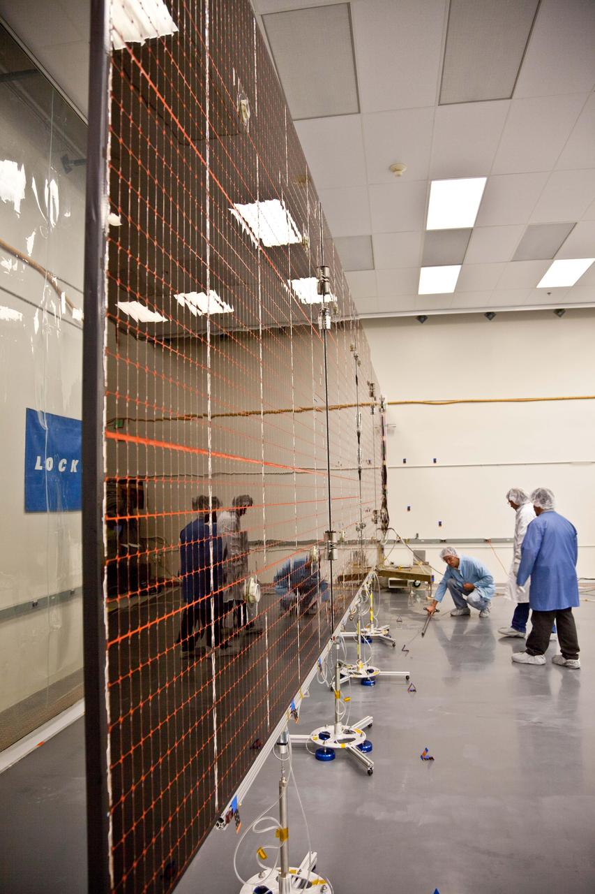
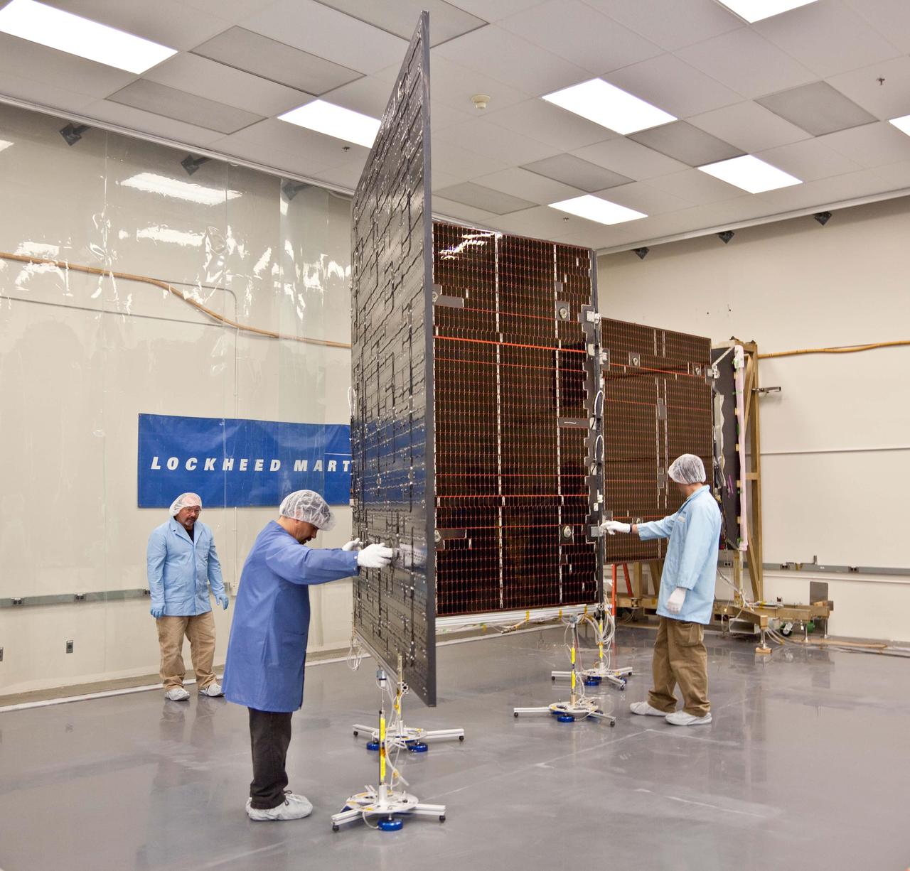
Technicians test the deployment of one of the three massive solar arrays that power NASA Juno spacecraft.
Technicians test the deployment of one of the three massive solar arrays that power NASA Juno spacecraft.
Technicians test the deployment of one of the three massive solar arrays that power NASA Juno spacecraft.
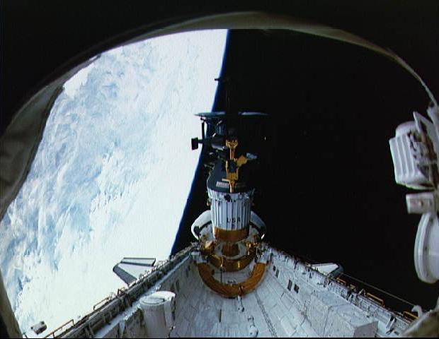
Deployment of NASA Galileo and the IUS from the cargo bay of STS-34 Atlantis at 7:15 p.m. EDT on October 18, 1989. P-35213
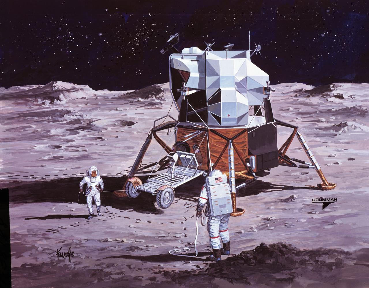
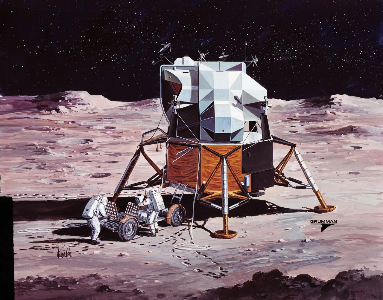
S71-38188 (26 June 1971) --- An artist's concept showing the Apollo 15 mission commander and the lunar module pilot performing deployment of the Lunar Roving Vehicle (LRV) on the lunar surface. The figure on the left represents astronaut James B. Irwin, lunar module pilot, who here is maintaining a constant pull on the deployment cable to help the LRV unfold, while astronaut David R. Scott (right), commander, pulls the tapes that lower the LRV to the surface. (This is the third in a series of Grumman Aerospace Corporation artist's concepts telling the lunar surface LRV deployment story of the Apollo 15 mission).
STS075-328-018 (25 Feb. 1996) --- Astronaut Franklin R. Chang-Diaz, STS-75 payload commander, is busy at the pilot's station during operations to deploy the Tethered Satellite System (TSS). His five crew mates (out of frame) were also on the flight deck, of the Earth-orbiting space shuttle Columbia, during the busy deployment activities.
Deployment of the +Y solar array after it has been integrated onto the GPM Core spacecraft. Credit: NASA/Goddard The Global Precipitation Measurement (GPM) mission is an international partnership co-led by NASA and the Japan Aerospace Exploration Agency (JAXA) that will provide next-generation global observations of precipitation from space. GPM will study global rain, snow and ice to better understand our climate, weather, and hydrometeorological processes. As of Novermber 2013 the GPM Core Observatory is in the final stages of testing at NASA Goddard Space Flight Center. The satellite will be flown to Japan in the fall of 2013 and launched into orbit on an HII-A rocket in early 2014. For more on the GPM mission, visit <a href="http://gpm.gsfc.nasa.gov/" rel="nofollow">gpm.gsfc.nasa.gov/</a>. <b><a href="http://www.nasa.gov/audience/formedia/features/MP_Photo_Guidelines.html" rel="nofollow">NASA image use policy.</a></b> <b><a href="http://www.nasa.gov/centers/goddard/home/index.html" rel="nofollow">NASA Goddard Space Flight Center</a></b> enables NASA’s mission through four scientific endeavors: Earth Science, Heliophysics, Solar System Exploration, and Astrophysics. Goddard plays a leading role in NASA’s accomplishments by contributing compelling scientific knowledge to advance the Agency’s mission. <b>Follow us on <a href="http://twitter.com/NASA_GoddardPix" rel="nofollow">Twitter</a></b> <b>Like us on <a href="http://www.facebook.com/pages/Greenbelt-MD/NASA-Goddard/395013845897?ref=tsd" rel="nofollow">Facebook</a></b> <b>Find us on <a href="http://instagram.com/nasagoddard?vm=grid" rel="nofollow">Instagram</a></b>
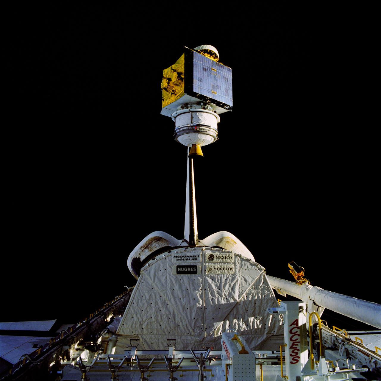
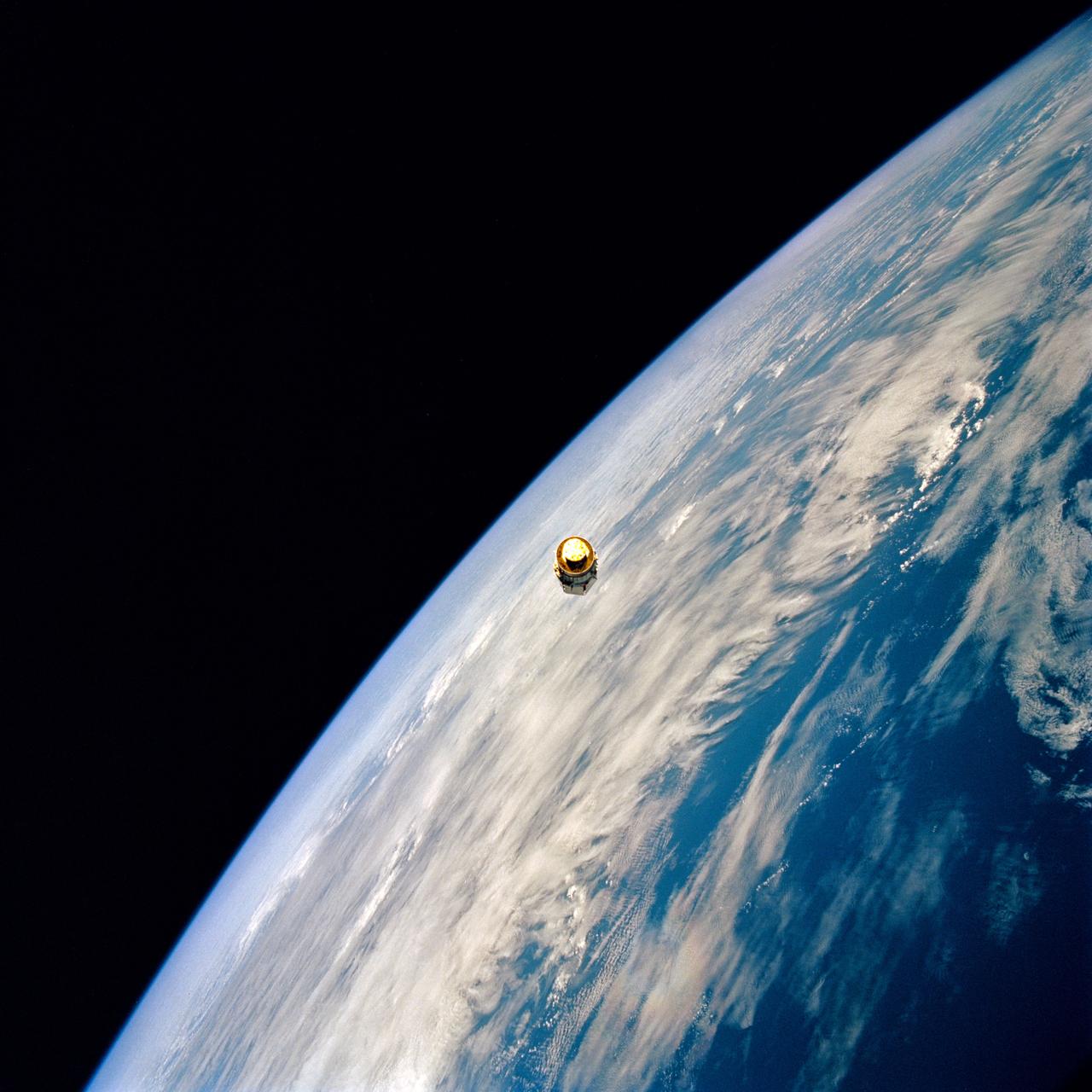
61B-38-36W (28 Nov 1985) --- The 4,144-pound RCA Satcom K-2 communications satellite is photographed as it spins from the cargo bay of the Earth-orbiting Atlantis. A TV camera at right records the deployment for a later playback to Earth. This frame was photographed with a handheld Hasselblad camera inside the spacecraft.
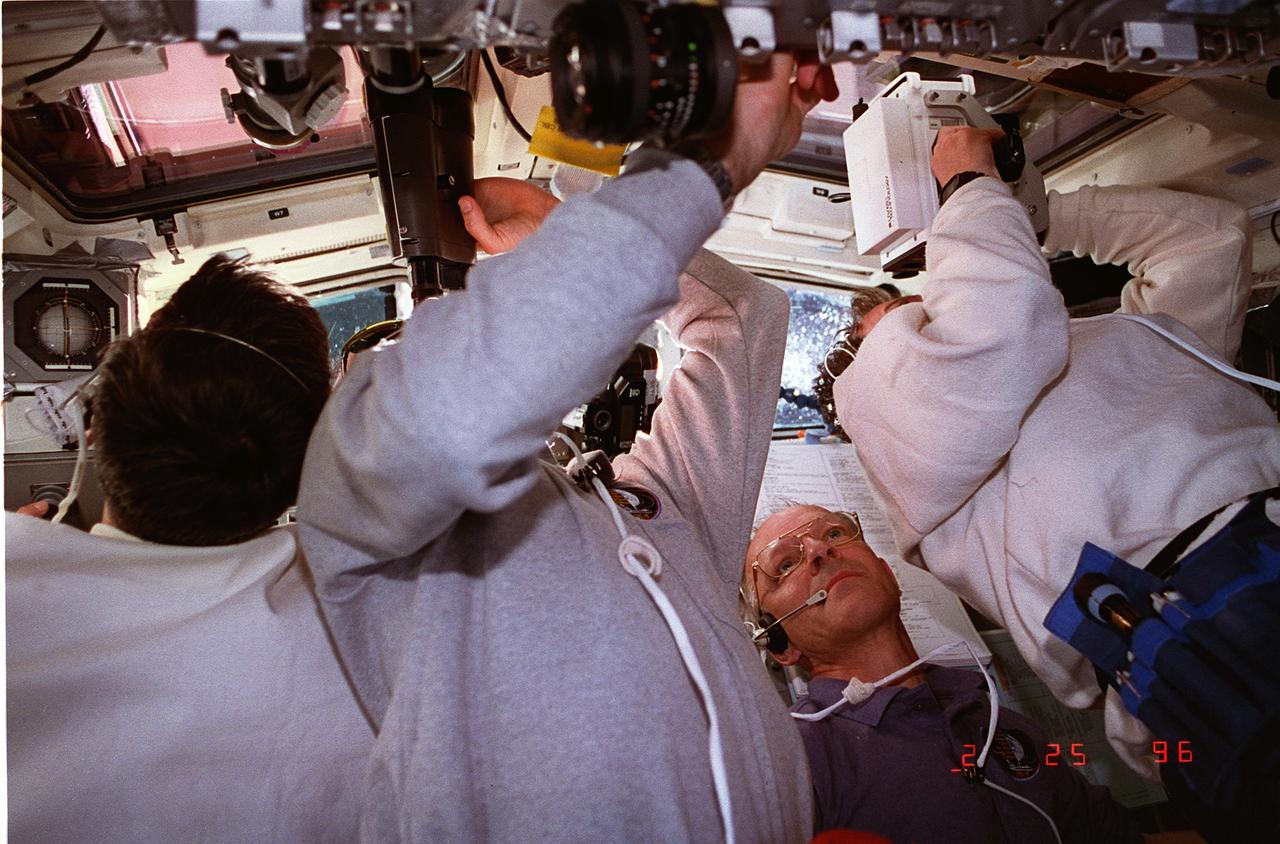
STS075-328-026 (25 Feb. 1996) --- Astronaut Claude Nicollier is the only clearly identifiable crewmember in this scene on the aft flight deck, captured during the busy chores associated with deployment of the Tethered Satellite System (TSS). The seven member crew was launched aboard the space shuttle Columbia on Feb. 22, 1996, and landed on March 9, 1996. Crewmembers were Andrew M. Allen, mission commander; Scott J. Horowitz, pilot; Franklin R. Chang-Diaz, payload commander; and Maurizio Cheli, European Space Agency (ESA); Jeffrey A. Hoffman and Nicollier, ESA, all mission specialists; along with payload specialist Umberto Guidoni of the Italian Space Agency (ASI).
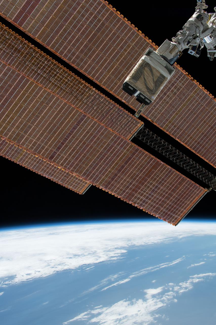
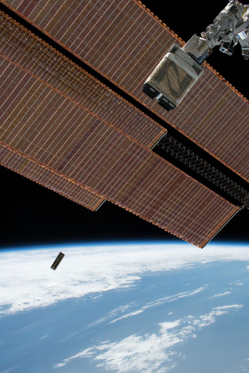
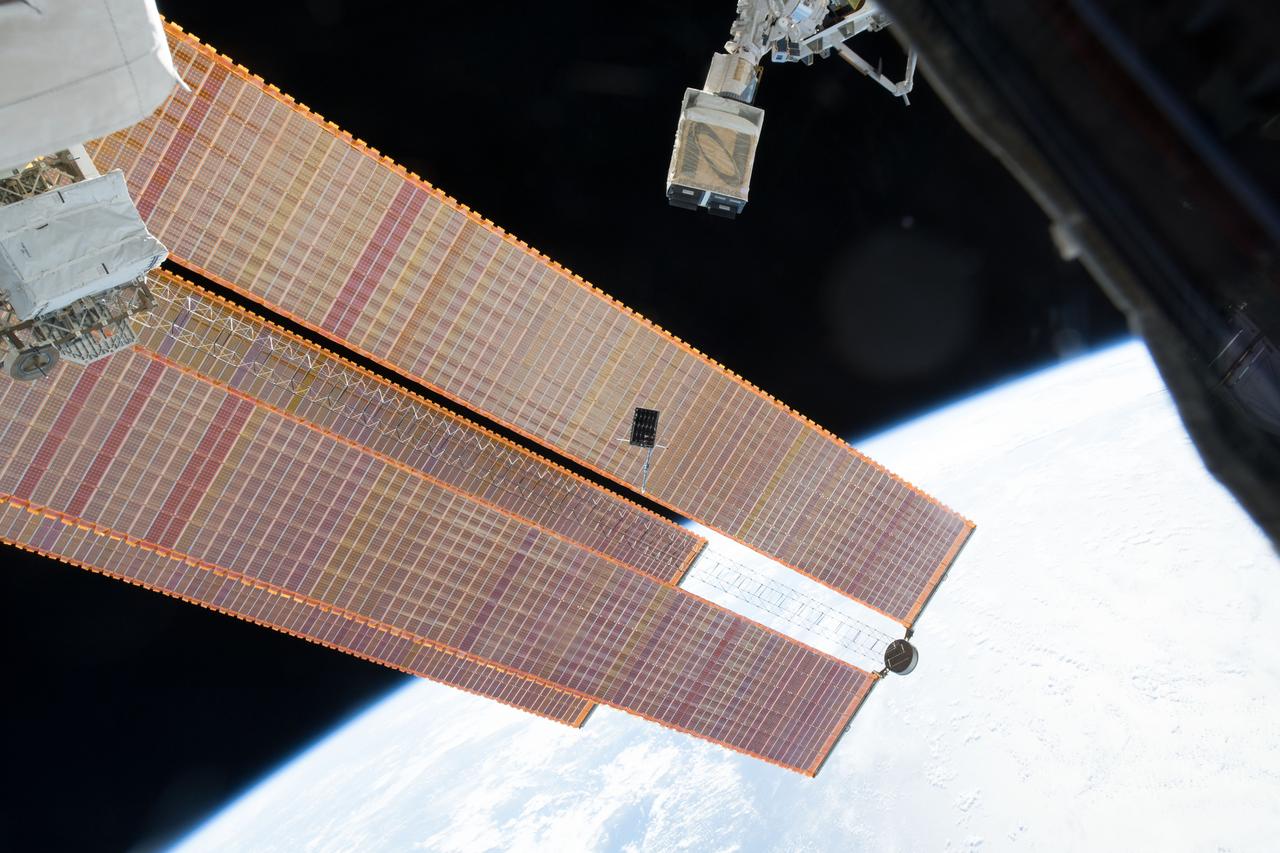
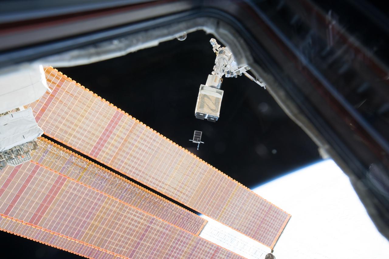
iss050e031664 (1/16/2017) --- Photo documentation of the Japanese-Small Satellite Orbital Deployer-6 (J-SSOD-6) deployment of the TuPOD Cubesat. TuPOD is a 3Unit micro-satellite that is entirely a 3D printed structure designed to launch the first Tubesats into space. The mission of TuPOD is to confirm that satellite deployment is feasible from CubeSat.

iss050e031653 (1/16/2017) --- Photo documentation of the Japanese-Small Satellite Orbital Deployer-6 (J-SSOD-6) deployment of the TuPOD Cubesat. TuPOD is a 3Unit micro-satellite that is entirely a 3D printed structure designed to launch the first Tubesats into space. The mission of TuPOD is to confirm that satellite deployment is feasible from CubeSat.

An engineer works on the Parachute Deployment Device of the Low-Density Supersonic Decelerator test vehicle in this image taken at the Missile Assembly Building at the U.S. Navy Pacific Missile Range Facility in Kauai, Hawaii.
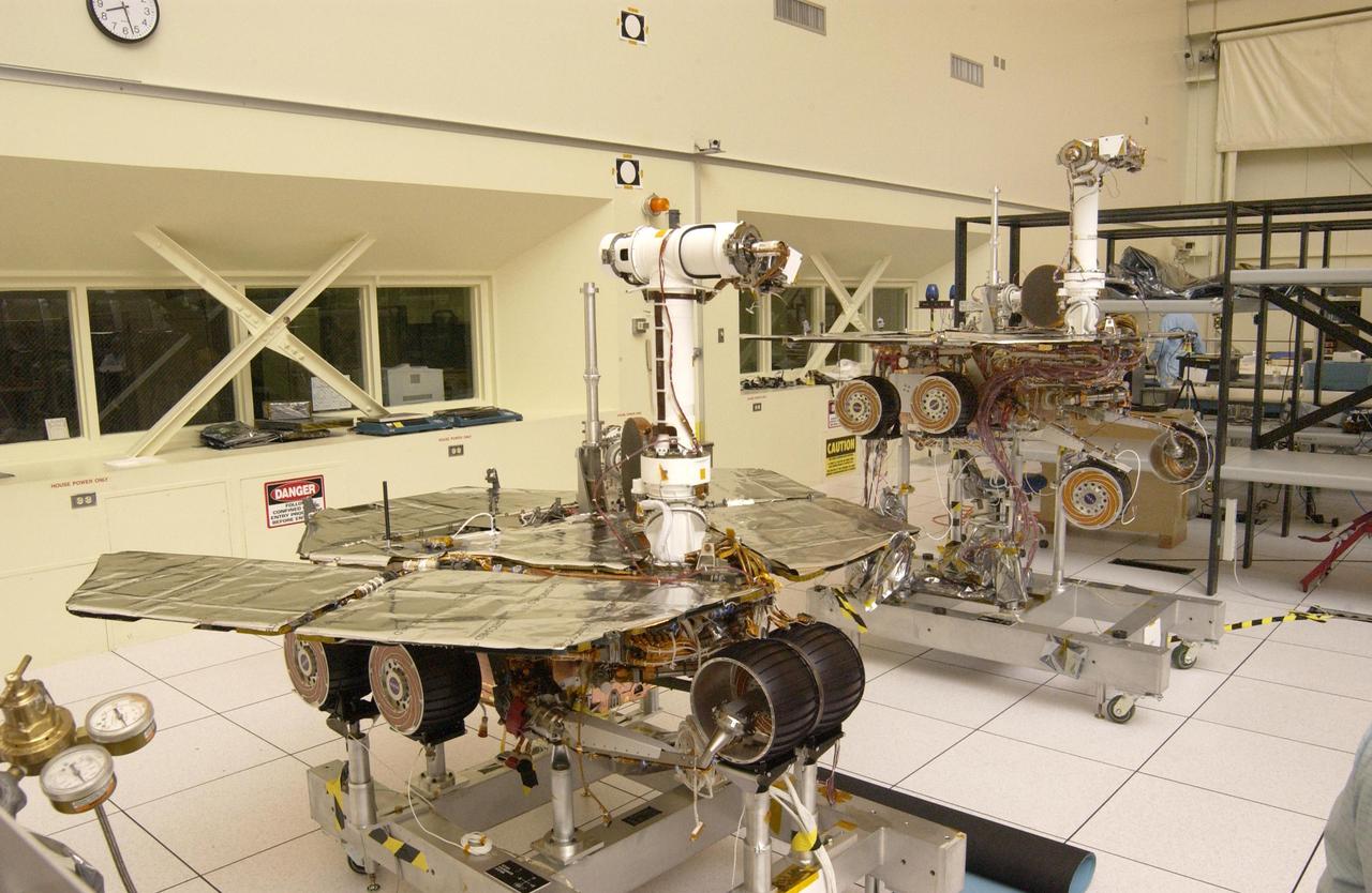
The twin rovers sit side-by-side in different stages of deployment. NASA Rover 2 left front wheels are stowed, while NASA Rover 1 front wheels are deployed.
S71-38189 (26 June 1971) --- An artist's concept showing the final steps of readying the Apollo 15 Lunar Roving Vehicle (LRV) or Rover 1 for mobility on the lunar surface. Performing the last few LRV deployment tasks here are, left to right, astronauts James B. Irwin, lunar module pilot, and David R. Scott, commander. More specifically the tasks depicted here include the setting up of the seats and the total releasing of the LRV from the LM. (This is the fourth in a series of four Grumman Aerospace Corporation artist's concepts telling the lunar surface LRV deployment story for Apollo 15).
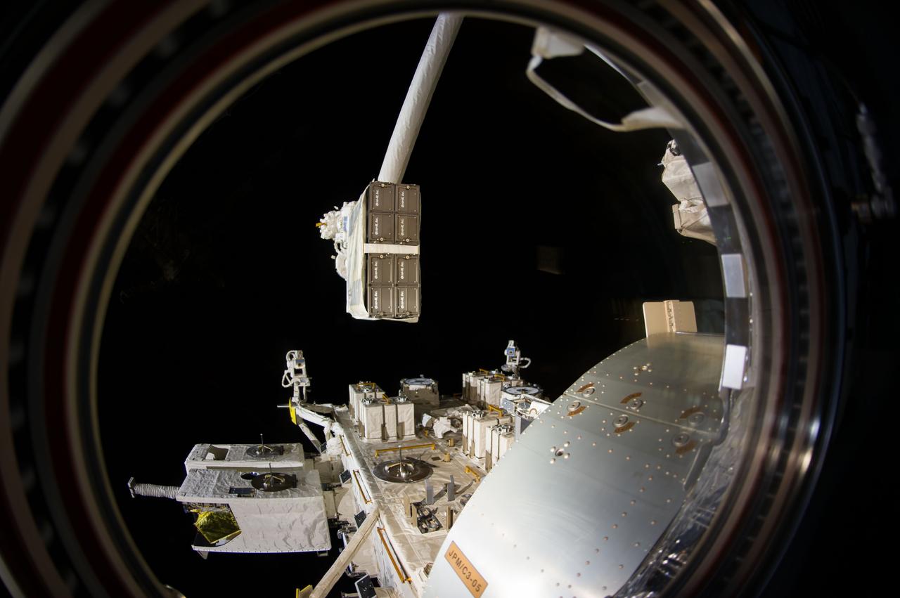
iss050e031207 (1/6/2017) --- A view during the Japanese-Small Satellite Orbital Deployer-6 (J-SSOD-6) deployment of the following satellites: Freedom (1U), Waseda-SAT3, ITF-2 (1U), Egg (3U), AOBA-Velox-III (U), TuPOD (3U). J-SSOD is a unique satellite launcher, handled by the Japanese Experiment Module Remote Manipulator System (JEMRMS), which provides containment and deployment mechanisms for several individual small satellites. Once the J-SSOD including satellite install cases with small satellites are installed on the Multi-Purpose Experiment Platform (MPEP) by crewmembers, it is passed through the JEM airlock for retrieval, positioning and deployment by the JEMRMS.
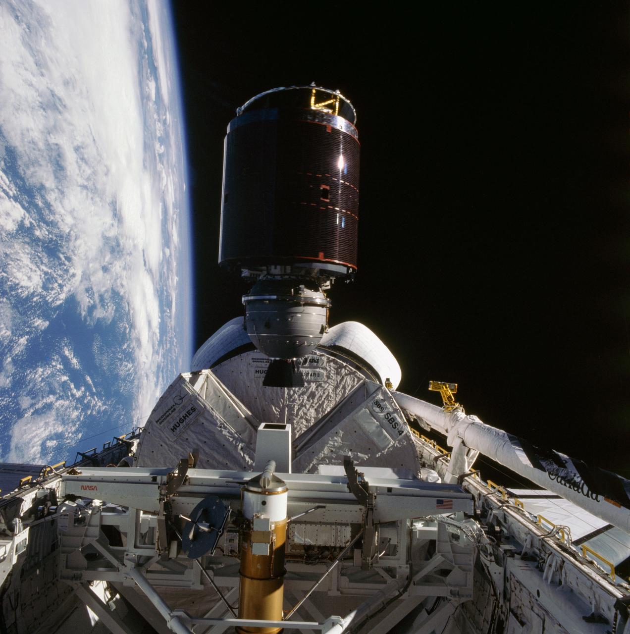
41D-36-034 (30 Aug 1984) --- Less than nine hours after the first launch of the Discovery, its astronaut crewmembers photographed deployment of the SBS-4 communications satellite. The cylindrical spacecraft spins and rises from its cradle-like protective shield to begin life in space. A number of maneuvers will place it in its desired orbit. A 70mm camera, aimed through the spacecraft’s aft flight deck windows, was used to expose the frame.
iss071e006845 (4/10/2024) --- View of the Japanese Experiment Module (JEM) Small Satellite Orbital Deployer-28 (J-SSOD-28) attached to the JEM Remote Manipulator System on the JEM Exposed Facility with the CURTIS experiment inside the deployer during Expedition 71. CURTIS is a 3U size satellite created through joint research between Panasonic HD and Kyutech. CURTIS carries out four different mission objectives to demonstrate technologies that can be used in future CubeSats.
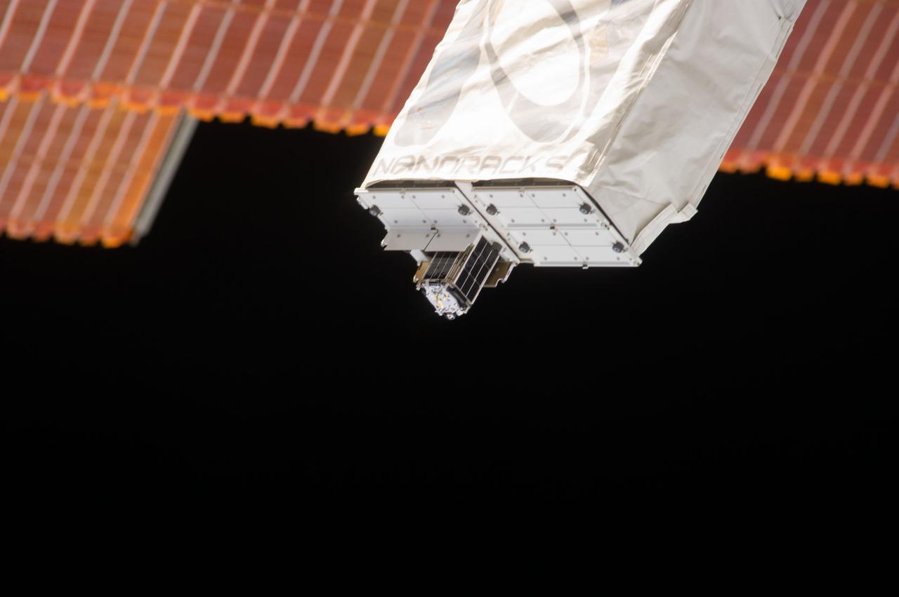
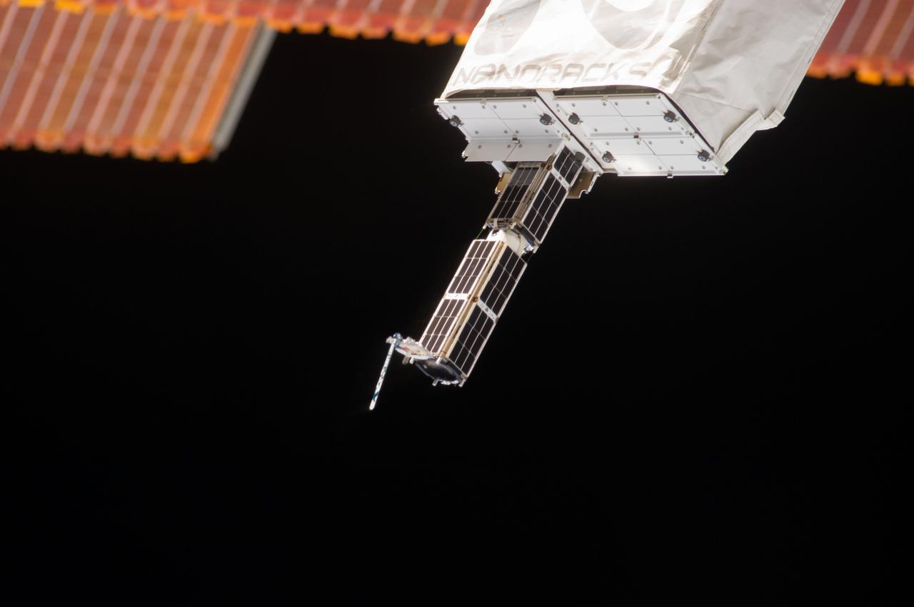
iss051e049985 )5/26/2017) --- A view of the NanoRacks CubeSat Deployer (NRCSD) 12 during the release of ExAlta-1, part of the NanoRacks-QB50 group of CubeSats. The NanoRacks CubeSat Deployer is a stackable, modular, ground loaded launch case. Each NanoRacks CubeSat Deployer accommodates up to 6.5U and eight launch cases are stacked for each JEM Airlock opening.
iss056e130478 (8/10/2018) --- A view of the BIRDS-2 Satellite Deployment during JSSOD-9 operations. The JEM Small Satellite Orbital Deployer (J-SSOD) provides a novel, safe, small satellite launching capability to the International Space Station (ISS). Once the J-SSOD including satellite install cases with small satellites are installed on the Multi-Purpose Experiment Platform (MPEP) by crewmembers, it is passed through the JEM airlock for retrieval, positioning and deployment by the JEMRMS.
iss050e031340 (1/16/2017) --- Photo documentation of the Japanese-Small Satellite Orbital Deployer-6 (J-SSOD-6) deployment of the ECG Cubesat. The EGG Satellite (re-Entry satellite with Gossamer aeroshell and GPS/Iridium) developed at the University of Tokyo, demonstrates a deployable aeroshell to first act as a drag device and then protect the satellite during the initial stages of re-entry.
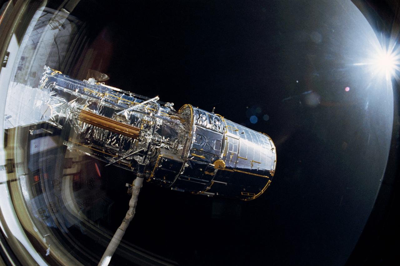
The Hubble Space Telescope (HST), grappled by Discovery's, Orbiter Vehicle (OV) 103's, remote manipulator system (RMS), is oriented in a 90 degree pitch position during STS-31 pre-deployment checkout procedures. The solar array (SA) panel (center) and high gain antennae (HGA) (on either side) are stowed along the Support System Module (SSM) forward shell prior to deployment. The sun highlights HST against the blackness of space.
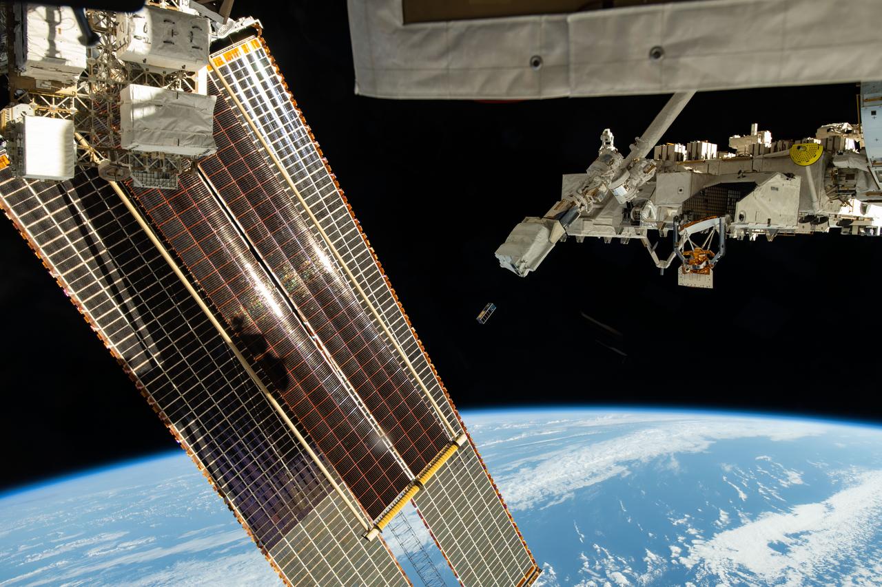
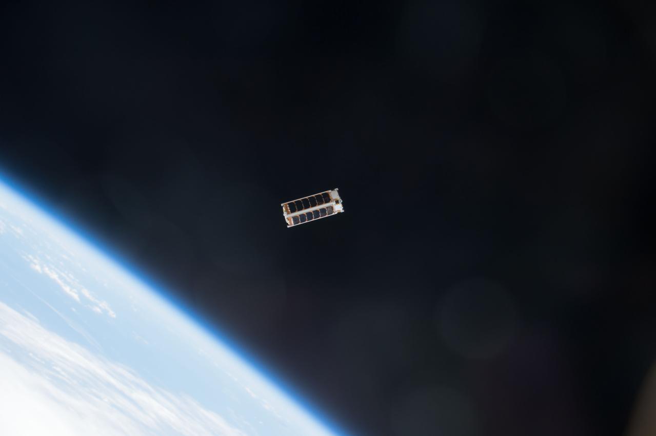
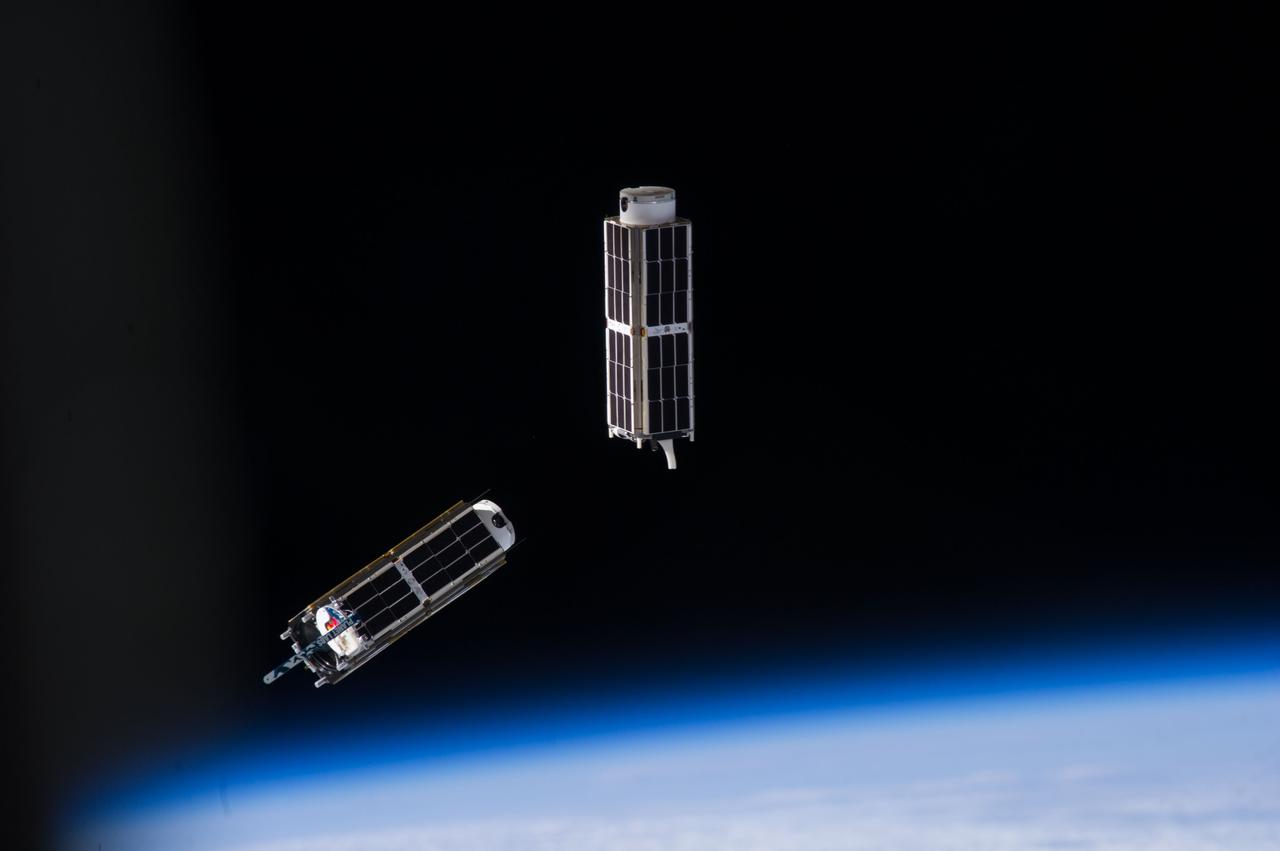
ISS038-E-044916 (11 Feb. 2014) --- A set of NanoRacks CubeSats is photographed by an Expedition 38 crew member after the deployment by the Small Satellite Orbital Deployer (SSOD). The CubeSats program contains a variety of experiments such as Earth observations and advanced electronics testing.
iss056e130490(8/10/2018) --- A view of the BIRDS-2 Satellite Deployment during JSSOD-9 operations. The JEM Small Satellite Orbital Deployer (J-SSOD) provides a novel, safe, small satellite launching capability to the International Space Station (ISS).
iss056e130515 (8/10/2018) --- A view of the BIRDS-2 Satellite Deployment during JSSOD-9 operations. The JEM Small Satellite Orbital Deployer (J-SSOD) provides a novel, safe, small satellite launching capability to the International Space Station (ISS).
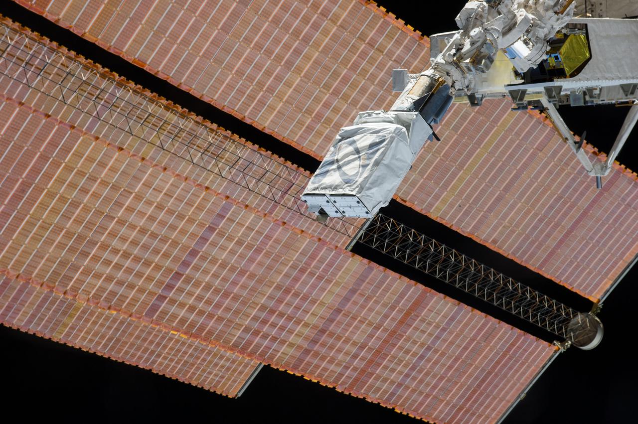
ISS038-E-044994 (11 Feb. 2014) --- The Small Satellite Orbital Deployer (SSOD), in the grasp of the Kibo laboratory robotic arm, is photographed by an Expedition 38 crew member on the International Space Station prior to the deployment of a set of NanoRacks CubeSats. The CubeSats program contains a variety of experiments such as Earth observations and advanced electronics testing.
ISS038-E-044883 (11 Feb. 2014) --- The Small Satellite Orbital Deployer (SSOD), in the grasp of the Kibo laboratory robotic arm, is photographed by an Expedition 38 crew member on the International Space Station as it begins the deployment of a set of NanoRacks CubeSats. The CubeSats program contains a variety of experiments such as Earth observations and advanced electronics testing.
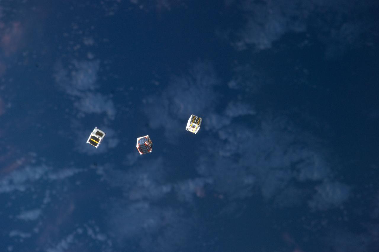
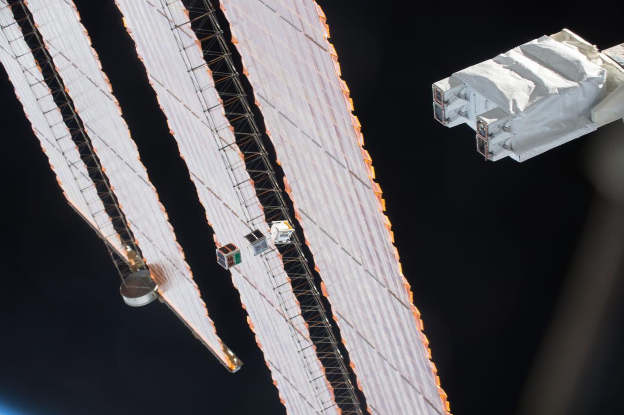
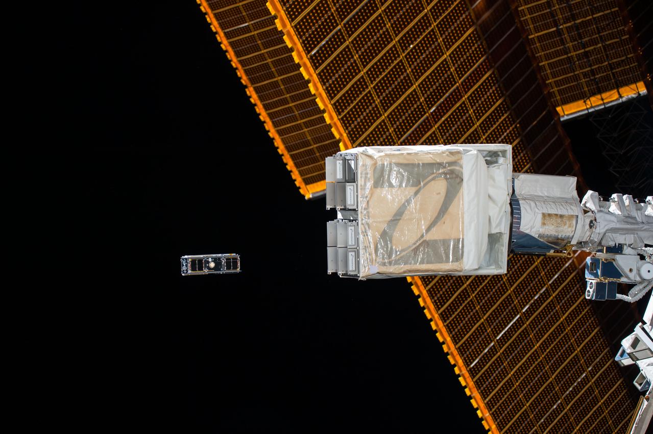
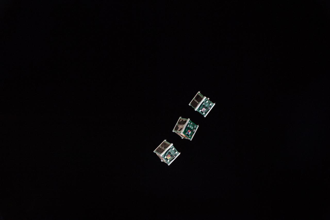
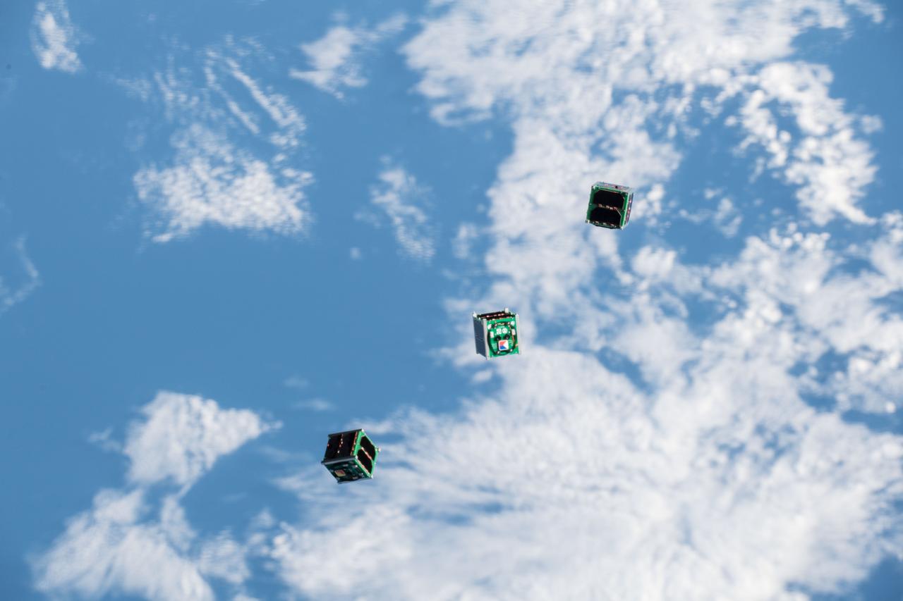
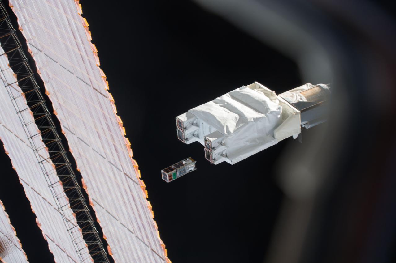
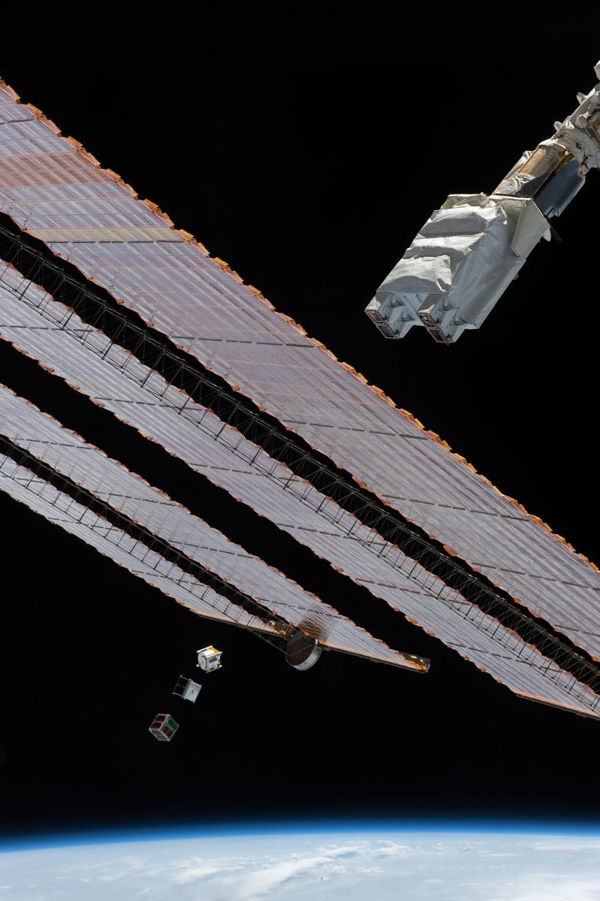
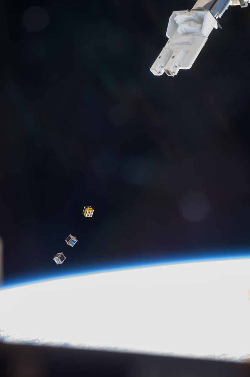
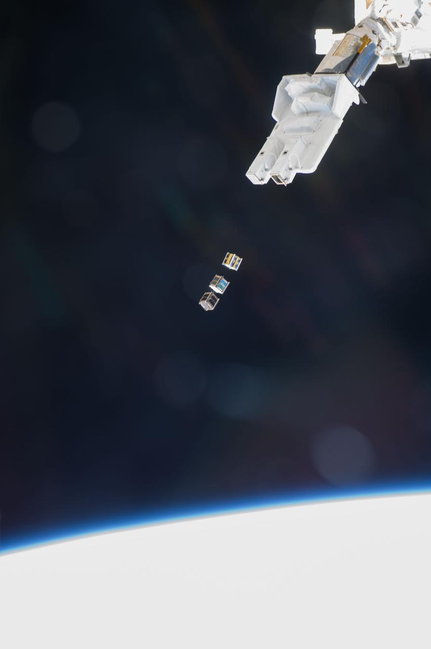
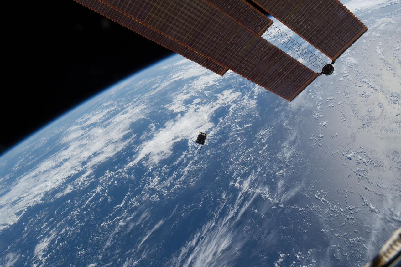
ISS033-E-009458 (4 Oct. 2012) --- Several tiny satellites are featured in this image photographed by an Expedition 33 crew member on the International Space Station. The satellites were released outside the Kibo laboratory using a Small Satellite Orbital Deployer attached to the Japanese module’s robotic arm on Oct. 4, 2012. Japan Aerospace Exploration Agency astronaut Aki Hoshide, flight engineer, set up the satellite deployment gear inside the lab and placed it in the Kibo airlock. The Japanese robotic arm then grappled the deployment system and its satellites from the airlock for deployment.
ISS033-E-009334 (4 Oct. 2012) --- Several tiny satellites are featured in this image photographed by an Expedition 33 crew member on the International Space Station. The satellites were released outside the Kibo laboratory using a Small Satellite Orbital Deployer attached to the Japanese module’s robotic arm on Oct. 4, 2012. Japan Aerospace Exploration Agency astronaut Aki Hoshide, flight engineer, set up the satellite deployment gear inside the lab and placed it in the Kibo airlock. The Japanese robotic arm then grappled the deployment system and its satellites from the airlock for deployment.
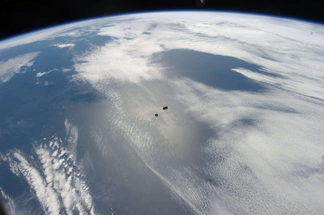
ISS033-E-009315 (4 Oct. 2012) --- Several tiny satellites are featured in this image photographed by an Expedition 33 crew member on the International Space Station. The satellites were released outside the Kibo laboratory using a Small Satellite Orbital Deployer attached to the Japanese module’s robotic arm on Oct. 4, 2012. Japan Aerospace Exploration Agency astronaut Aki Hoshide, flight engineer, set up the satellite deployment gear inside the lab and placed it in the Kibo airlock. The Japanese robotic arm then grappled the deployment system and its satellites from the airlock for deployment. A blue and white part of Earth provides the backdrop for the scene.

This image shows the deployment of a half-scale starshade with four petals at NASA's Jet Propulsion Laboratory in Pasadena, California, in 2014. The full scale of this starshade (not shown) will measure at 34 meters, or approximately 111 feet. The flower-like petals of the starshade are designed to diffract bright starlight away from telescopes seeking the dim light of exoplanets. The starshade was re-designed from earlier models to allow these petals to furl, or wrap around the spacecraft, for launch into space. Once in space, the starshade will need to expand from its tightly-packed launch shape to become large and umbrella-like, ideal for blocking starlight. Each petal is covered in a high-performance plastic film that resembles gold foil. On a starshade ready for launch, the thermal gold foil will only cover the side of the petals facing away from the telescope, with black on the other, so as not to reflect other light sources such as the Earth into its lens. Starlight-blocking technologies such as the starshade are being developed to help image exoplanets, with a focus on Earth-sized, habitable worlds. http://photojournal.jpl.nasa.gov/catalog/PIA20907
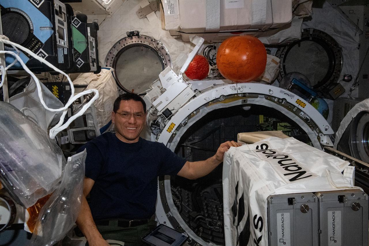
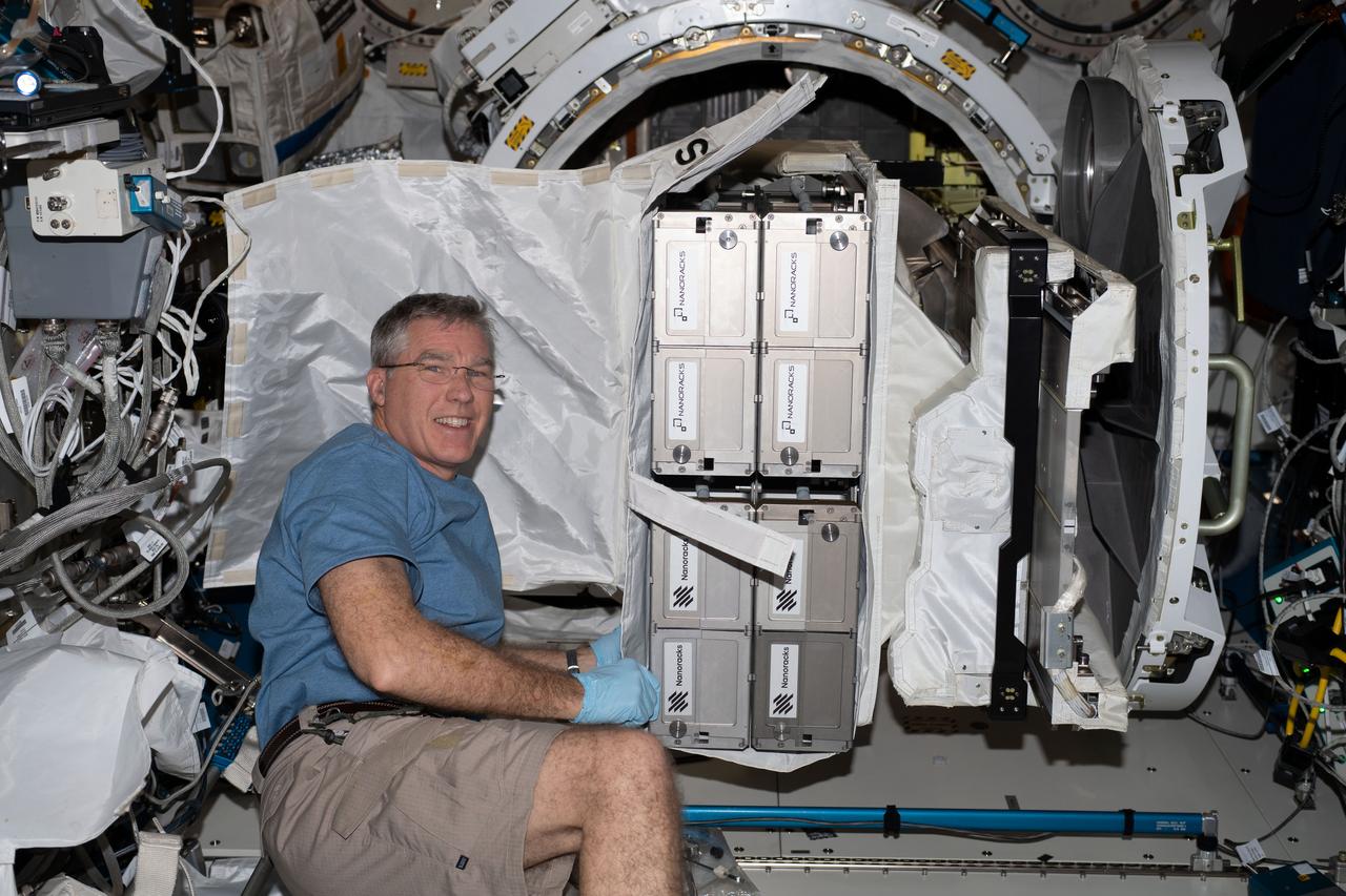
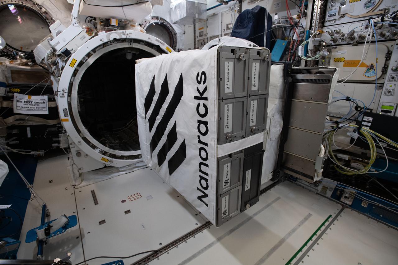
iss069e004397 (April 20, 2023) --- NASA astronaut and Expedition 69 Flight Engineer Frank Rubio works to install the NanoRacks CubeSat Deployer inside the Kibo laboratory module's airlock. After the airlock is depressurized, the Japanese robotic arm grapples the deployer and places it outside in the vacuum of microgravity pointing it away from the International Space Station. CubeSats from private, governmental, and academic organizations are then deployed into Earth orbit for a variety of research objectives.
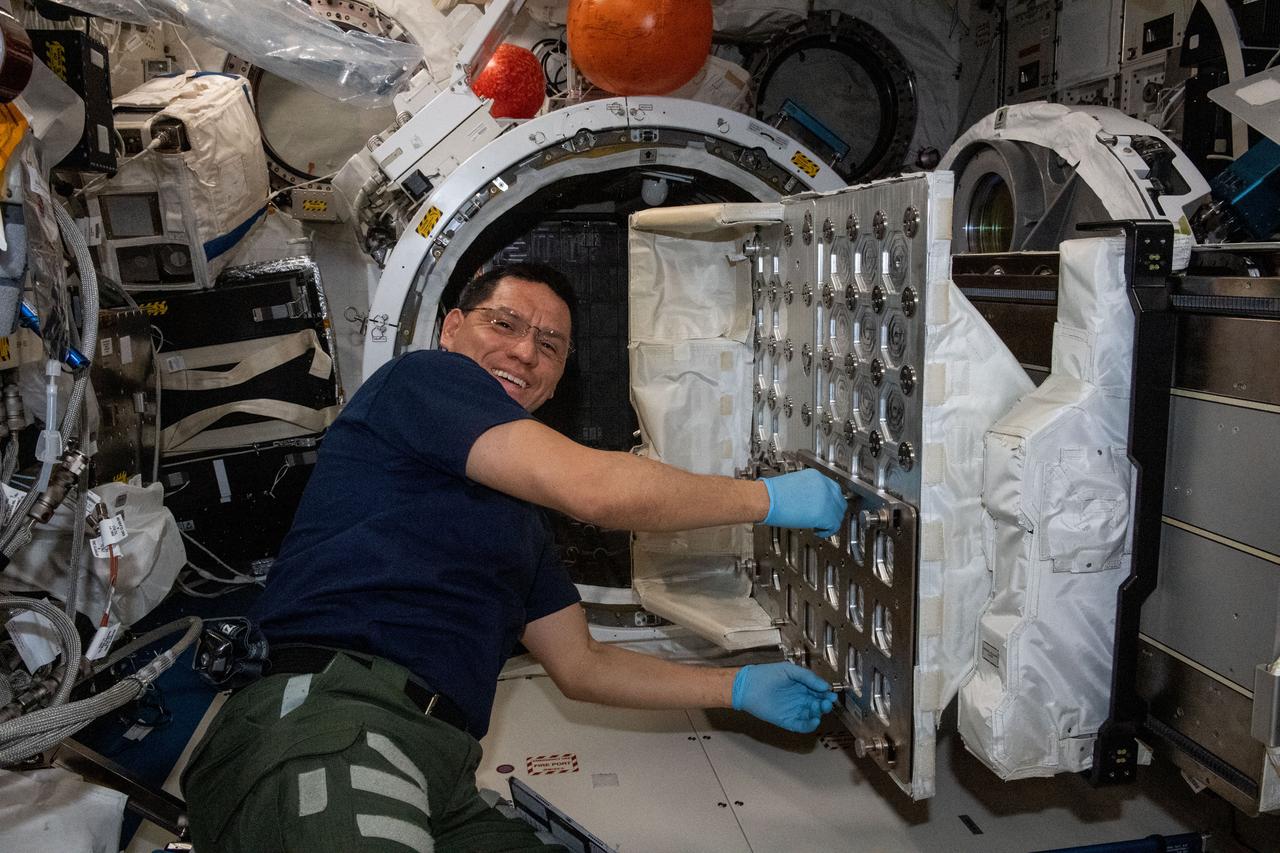
iss069e004389 (April 20, 2023) --- NASA astronaut and Expedition 69 Flight Engineer Frank Rubio works to install the NanoRacks CubeSat Deployer inside the Kibo laboratory module's airlock. After the airlock is depressurized, the Japanese robotic arm grapples the deployer and places it outside in the vacuum of microgravity pointing it away from the International Space Station. CubeSats from private, governmental, and academic organizations are then deployed into Earth orbit for a variety of research objectives.
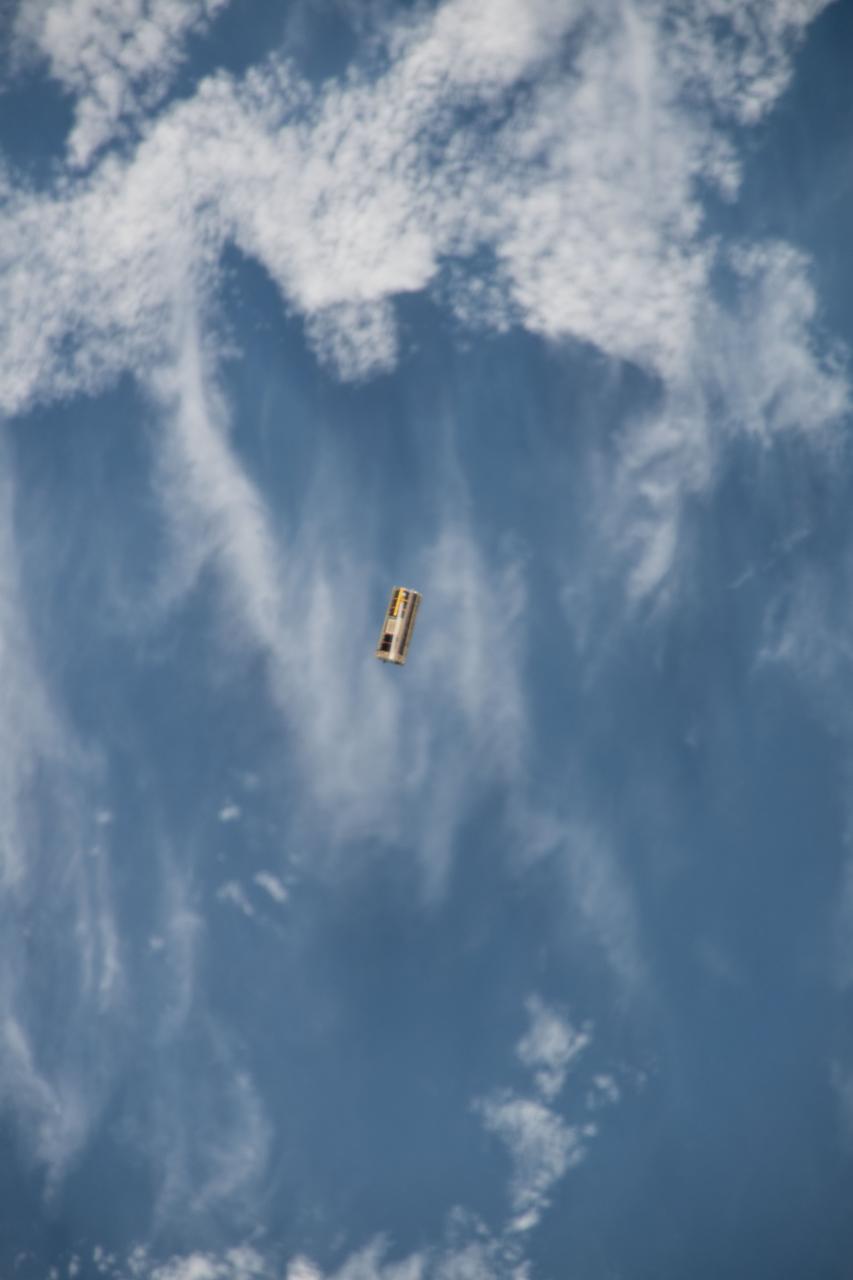
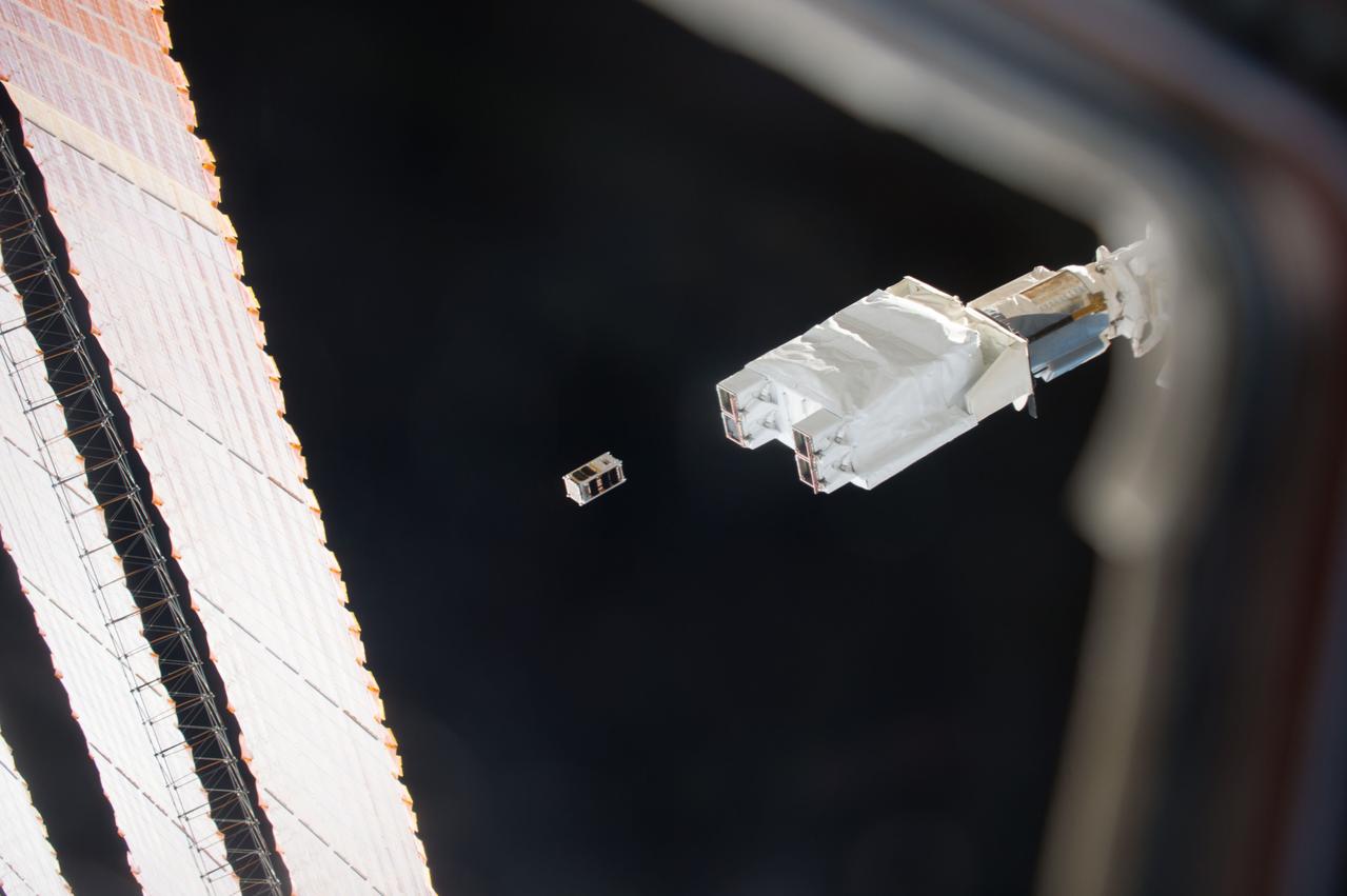
iss053e234625 (11/21/2017) --- A view of OSIRIS-3U Satellite Deployer Number 8 after deployment from the NanoRacks CubeSat Deployer Number 13. OSIRIS-3U is an integrated CubeSat that conducts measurements of the Earth’s ionosphere, in coordination with a ground-based astronomy observatory.
iss053e234621 (11/21/2017) --- A view of OSIRIS-3U Satellite Deployer Number 8 after deployment from the NanoRacks CubeSat Deployer Number 13. OSIRIS-3U is an integrated CubeSat that conducts measurements of the Earth’s ionosphere, in coordination with a ground-based astronomy observatory.
iss053e234598 (11/21/2017) --- A view of OSIRIS-3U Satellite Deployer Number 8 after deployment from the NanoRacks CubeSat Deployer Number 13. OSIRIS-3U is an integrated CubeSat that conducts measurements of the Earth’s ionosphere, in coordination with a ground-based astronomy observatory.
iss053e234606 (11/21/2017) --- A view of OSIRIS-3U Satellite Deployer Number 8 after deployment from the NanoRacks CubeSat Deployer Number 13. OSIRIS-3U is an integrated CubeSat that conducts measurements of the Earth’s ionosphere, in coordination with a ground-based astronomy observatory.
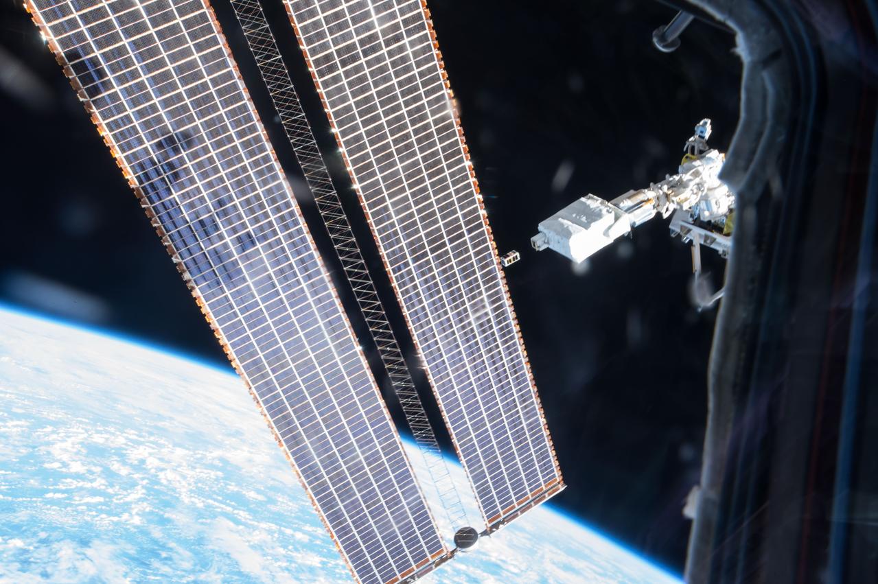
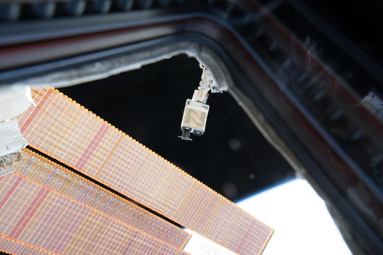
ISS040-E-100890 (19 Aug. 2014) --- Through a window in the International Space Station?s Kibo laboratory, an Expedition 40 crew member photographed the CubeSat deployer mechanism in the grasp of the Japanese robotic arm prior to a series of NanoRacks CubeSat miniature satellite deployments.
ATK Solar Array Deployment Test at NASA Plum Brook Station Space Power Facility.
iss069e025743 (June 28, 2023) --- NASA astronaut and Expedition 69 Flight Engineer Stephen Bowen installs the NanoRacks CubeSat Deployer into the Kibo laboratory module's airlock.
iss050e031525 (1/16/2017) --- Photo documentation of the Japanese-Small Satellite Orbital Deployer-6 (J-SSOD-6) deployment of the AOBA-Velox-3 Cubesat. The AOBA-Velox-3 mission is a joint mission between Nanyang Technological University (NTU), Singapore and the Kyushu Institute of Technology (Kyutech), Japan. This 2-Unit (2U) micro-satellite tests a micro-propulsion system, Pulse Plasma Thruster, PPT designed by NTU, that allows the spacecraft to remain in orbit up to six months.
iss050e031566 (1/16/2017) --- Photo documentation of the Japanese-Small Satellite Orbital Deployer-6 (J-SSOD-6) deployment of the AOBA-Velox-3 Cubesat. The AOBA-Velox-3 mission is a joint mission between Nanyang Technological University (NTU), Singapore and the Kyushu Institute of Technology (Kyutech), Japan. This 2-Unit (2U) micro-satellite tests a micro-propulsion system, Pulse Plasma Thruster, PPT designed by NTU, that allows the spacecraft to remain in orbit up to six months.
iss047e120450 (5/16/2016) --- Photographic documentation of NanoRacks CubeSat Deployer Number 8 Deployment Operations. The tiny four-inch and about three-pound cube satellite named St. Thomas More School Cathedral Satellite-1 (STMSat-1) is delivered by a resupply rocket to the International Space Station (ISS) where it is deployed by an ISS NanoRacks launcher into its own orbit to capture images and transmit them back to the schools around the world for research and teaching purposes in math and science.
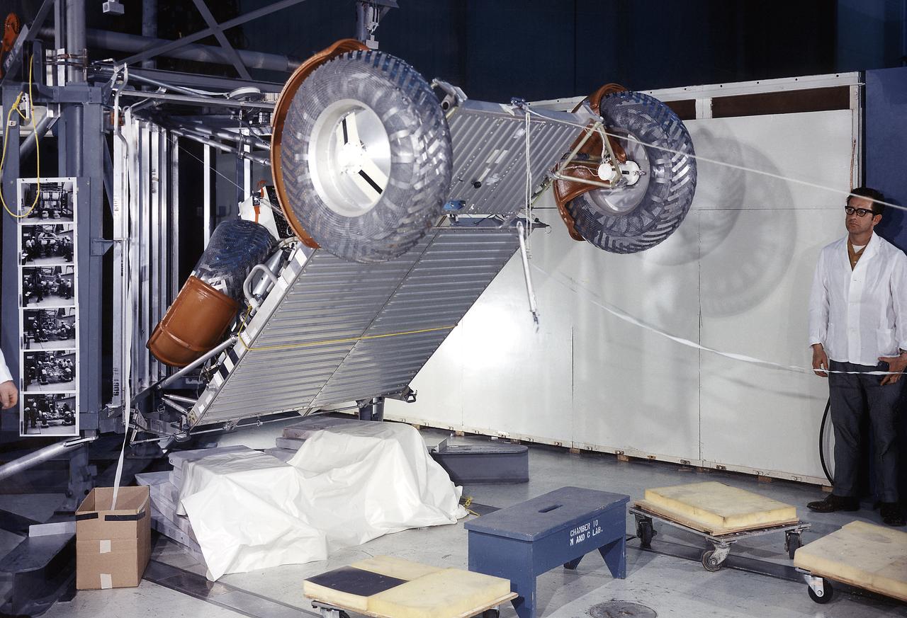
This photograph was taken during a deployment simulation of the Lunar Roving Vehicle (LRV). The LRV was built to give Apollo astronauts a greater range of mobility during the last three lunar exploration missions; Apollo 15, Apollo 16, and Apollo 17. It was designed and developed by the Marshall Space Flight Center and built by the Boeing Company.
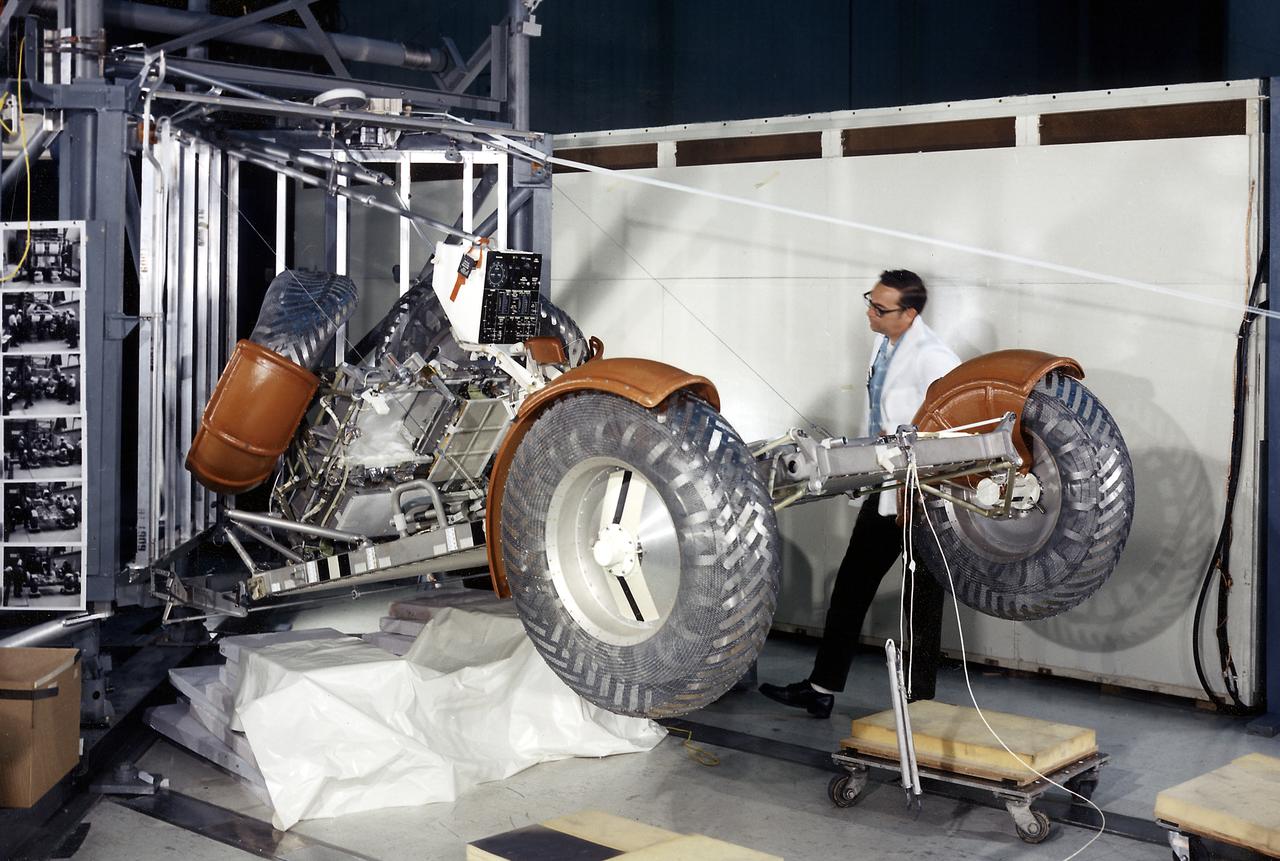
This photograph was taken during a deployment simulation of the Lunar Roving Vehicle (LRV). The LRV was built to give Apollo astronauts a greater range of mobility during the last three lunar exploration missions; Apollo 15, Apollo 16, and Apollo 17. It was designed and developed by the Marshall Space Flight Center and built by the Boeing Company.

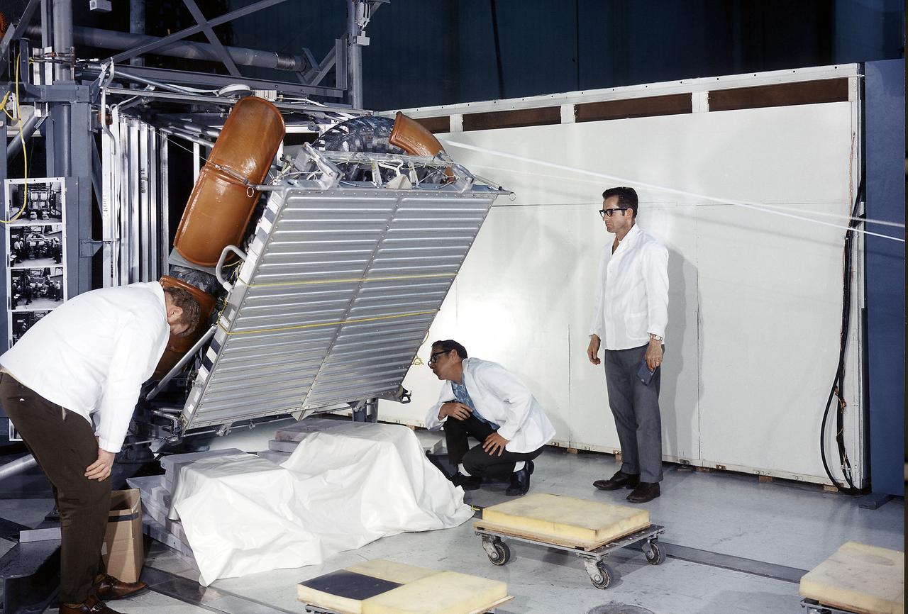
This photograph was taken during a deployment simulation of the Lunar Roving Vehicle (LRV). The LRV was built to give Apollo astronauts a greater range of mobility during the last three lunar exploration missions; Apollo 15, Apollo 16, and Apollo 17. It was designed and developed by the Marshall Space Flight Center and built by the Boeing Company.
This photograph was taken during a deployment simulation of the Lunar Roving Vehicle (LRV). The LRV was built to give Apollo astronauts a greater range of mobility during the last three lunar exploration missions; Apollo 15, Apollo 16, and Apollo 17. It was designed and developed by the Marshall Space Flight Center and built by the Boeing Company.
iss050e031198 (1/17/2017) --- Photo documentation of the Japanese-Small Satellite Orbital Deployer-6 (J-SSOD-6) deployment of the ITF-2, Waseda-SAT3 and Freedom CubeSats. The Imagine The Future-2 (ITF-2) CubeSat mission supports amateur radio networking by testing a micro engineered 1/20 wavelength small antenna. The WASEDA SAT-3 is a CubeSat developed by Waseda University aiming to test an ultra-light drag chute for accelerated deorbit. An LCD projector shows images on the chute with imagery sent back to Earth via an onboard camera. FREEDOM is a 1 Unit (1U) CubeSat developed by the Nakashimada Engineering Works and the Tohoku University to demonstrate a deployable deorbit device “DOM” for application in future missions for space debris mitigation.
iss050e032565 (1/17/2017) --- Photo documentation of the Japanese-Small Satellite Orbital Deployer-6 (J-SSOD-6) deployment of the ITF-2, Waseda-SAT3 and Freedom CubeSats. The Imagine The Future-2 (ITF-2) CubeSat mission supports amateur radio networking by testing a micro engineered 1/20 wavelength small antenna. The WASEDA SAT-3 is a CubeSat developed by Waseda University aiming to test an ultra-light drag chute for accelerated deorbit. An LCD projector shows images on the chute with imagery sent back to Earth via an onboard camera. FREEDOM is a 1 Unit (1U) CubeSat developed by the Nakashimada Engineering Works and the Tohoku University to demonstrate a deployable deorbit device “DOM” for application in future missions for space debris mitigation.
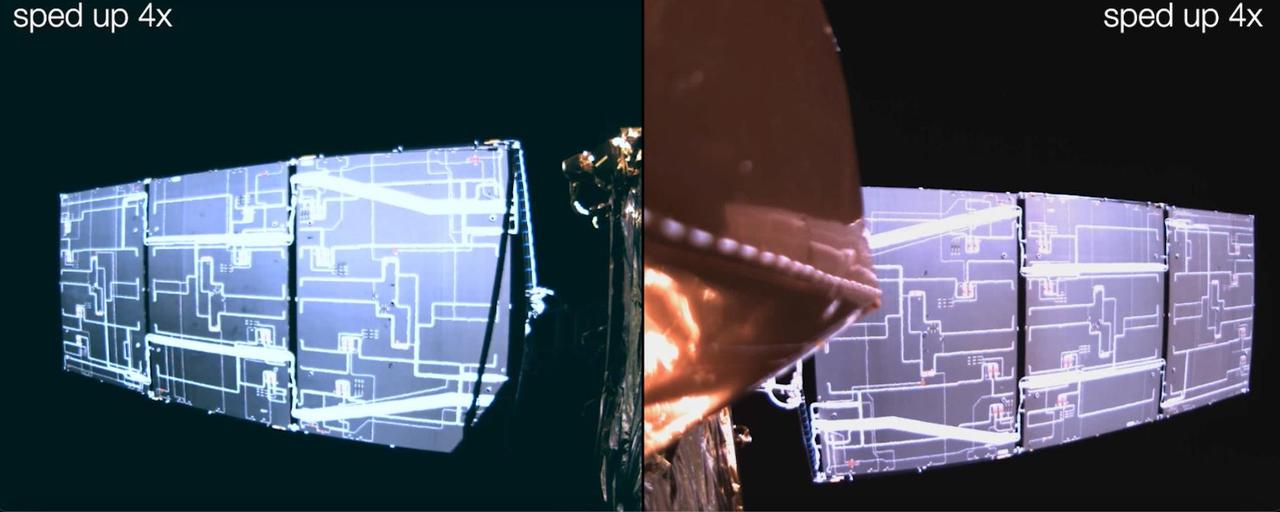
This video is a series of images showing the deployment of the solar arrays that power the international Surface Water and Ocean Topography satellite (SWOT). The mission captured the roughly 10-minute process with two of the four commercial cameras aboard the satellite (the same type used to capture NASA's Perseverance rover landing on Mars). The satellite launched Dec. 16, 2022, at 3:46 a.m. PST from Vandenberg Space Force Base in California, and the arrays started their deployment at 5:01 a.m. PST. SWOT's two solar arrays measure 48.8 feet (14.9 meters) from end to end, with a total surface area of 335 square feet (31 square meters). Extending from opposite sides of the spacecraft bus, the arrays remain pointed at the Sun via small motors. They provide 8 kilowatts of power to the satellite, which has a 1.5-kilowatt total power demand. SWOT will survey the height of water in Earth's lakes, rivers, reservoirs, and the ocean. The satellite will cover the planet's surface at least once every 21 days and has a prime mission of three years. It was jointly developed by NASA and France's Centre National d'Études Spatiales (CNES), with contributions from the Canadian Space Agency (CSA) and the UK Space Agency. Movie available at https://photojournal.jpl.nasa.gov/catalog/PIA25563
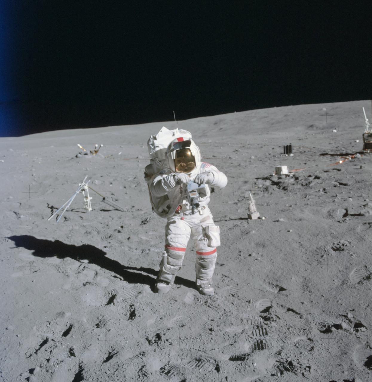
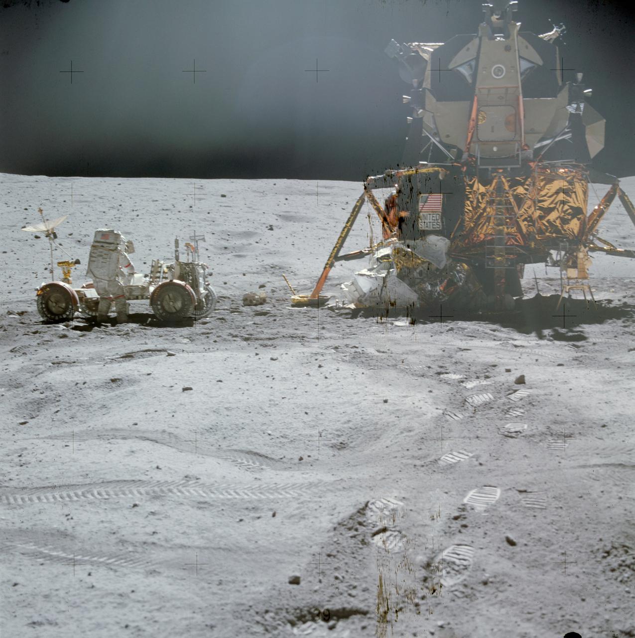
AS16-114-18388 (21 April 1972) --- Astronaut John W. Young, commander of the Apollo 16 lunar landing mission, stands at the Apollo Lunar Surface Experiments Package (ALSEP) deployment site during the first Apollo 16 extravehicular activity (EVA) at the Descartes landing site. The components of the ALSEP are in the background. The lunar surface drill is just behind and to the right of astronaut Young. The drill's rack and bore stems are to the left. The three-sensor Lunar Surface Magnetometer is beyond the rack. The dark object in the right background is the Radioisotope Thermoelectric Generator (RTG). Between the RTG and the drill is the Heat Flow Experiment. A part of the Central Station is at the right center edge of the picture. This photograph was taken by astronaut Charles M. Duke Jr., lunar module pilot.
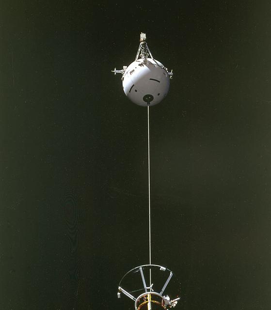
This is a Space Shuttle Orbiter Atlantis (STS-46) onboard photo of the Tethered Satellite System (TSS-1) deployment. A cooperative development effort by the Italian Space Agency (ASI) and NASA, the Tethered Satellite System (TSS) made capable the deployment and retrieval of a satellite which is attached by a wire tether from distances up to 100 km from the Orbiter. These free-flying satellites are used as observation platforms outside of the Orbiter.
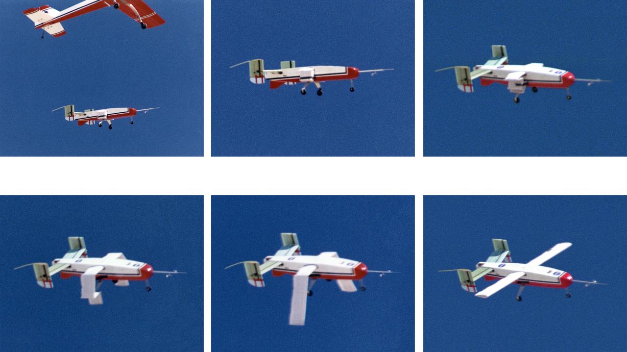
The deployable, inflatable wing technology demonstrator aircraft's wings begin deploying following separation from its carrier aircraft during a flight experiment conducted by the NASA Dryden Flight Research Center, Edwards, California. Wing deployment time is typically on the order of a third of a second, almost faster than the human eye can see. Three successful flights of the I2000 inflatable wing aircraft occurred. During the flights, the team air-launched the radio-controlled (R/C) I2000 from an R/C utility airplane at an altitude of 800-1000 feet. As the I2000 separated from the carrier aircraft, its inflatable wings "popped-out," deploying rapidly via an on-board nitrogen bottle. The aircraft remained stable as it transitioned from wingless to winged flight. The unpowered I2000 glided down to a smooth landing under complete control.
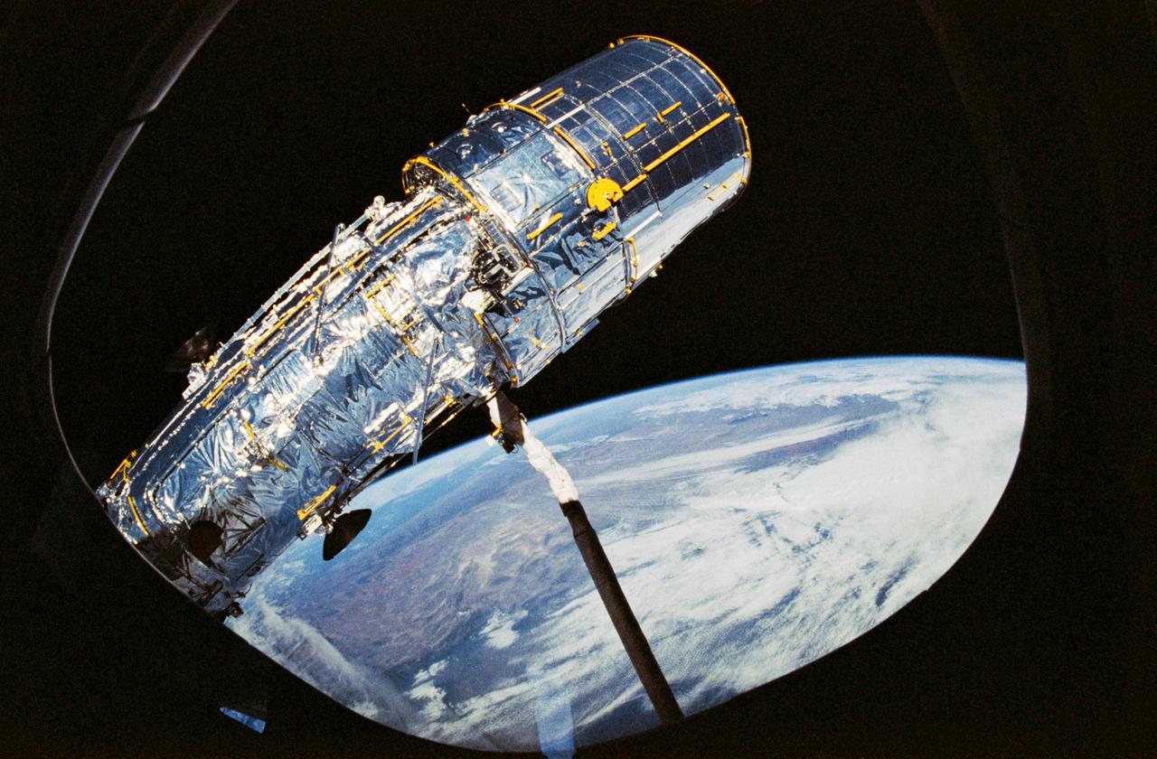
STS031-10-023 (25 April 1990) --- View of the Hubble Space Telescope (HST) on the end of Discovery's Remote Manipulator System (RMS) arm prior to deployment of its antennae and solar array panels.
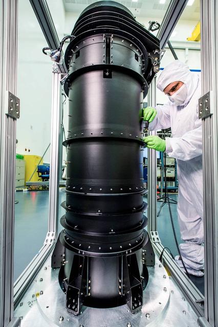
Building a space telescope to see the light from the earliest stars of our universe is a pretty complex task. Although much of the attention goes to instruments and the giant mirrors on NASA's James Webb Space Telescope, there are other components that have big jobs to do and that required imagination, engineering, and innovation to become a reality. For example, engineers working on the Webb telescope have to think of everything from keeping instruments from overheating or freezing, to packing up the Webb, which is as big as a tennis court, to fit inside the rocket that will take it to space. Those are two areas where the "DTA" or Deployable Tower Assembly (DTA) plays a major role. The DTA looks like a big black pipe and is made out of graphite-epoxy composite material to ensure stability and strength with extreme changes in temperature like those encountered in space. When fully deployed, the DTA reaches ten feet in length. The DTA interfaces and supports the spacecraft and the telescope structures. It features two large nested telescoping tubes, connected by a mechanized lead screw. It is a deployable structure that is both very light and extremely strong and stable. The Webb telescope’s secondary mirror support structure and DTA contribute to how the telescope and instruments fit into the rocket fairing in preparation for launch. The DTA allows the Webb to be short enough when stowed to fit in the rocket fairing with an acceptably low center of gravity for launch. Several days after the Webb telescope is launched, the DTA will deploy, or separate, the telescope mirrors and instruments from the spacecraft bus and sunshield. This separation allows the sunshield to unfurl and shade the telescope and instruments from radiant heat and stray light from the sun and Earth. The DTA was designed, built and tested by Astro Aerospace - a Northrop Grumman Company, in Carpinteria, California. The James Webb Space Telescope is the scientific successor to NASA's Hubble Space Telescope. It will be the most powerful space telescope ever built. The Webb telescope is an international project led by NASA with its partners, the European Space Agency and the Canadian Space Agency. For more information about the Webb telescope, visit: <a href="http://www.nasa.gov/webb" rel="nofollow">www.nasa.gov/webb</a> or jwst.nasa.gov <b><a href="http://www.nasa.gov/audience/formedia/features/MP_Photo_Guidelines.html" rel="nofollow">NASA image use policy.</a></b> <b><a href="http://www.nasa.gov/centers/goddard/home/index.html" rel="nofollow">NASA Goddard Space Flight Center</a></b> enables NASA’s mission through four scientific endeavors: Earth Science, Heliophysics, Solar System Exploration, and Astrophysics. Goddard plays a leading role in NASA’s accomplishments by contributing compelling scientific knowledge to advance the Agency’s mission. <b>Follow us on <a href="http://twitter.com/NASAGoddardPix" rel="nofollow">Twitter</a></b> <b>Like us on <a href="http://www.facebook.com/pages/Greenbelt-MD/NASA-Goddard/395013845897?ref=tsd" rel="nofollow">Facebook</a></b> <b>Find us on <a href="http://instagrid.me/nasagoddard/?vm=grid" rel="nofollow">Instagram</a></b>
iss065e444435 (10/11/2021) --- A view of NanoRacks CubeSat Deployers hardware on the MPEP (Multipurpose Experiment Platform) aboard the International Space Station (ISS).
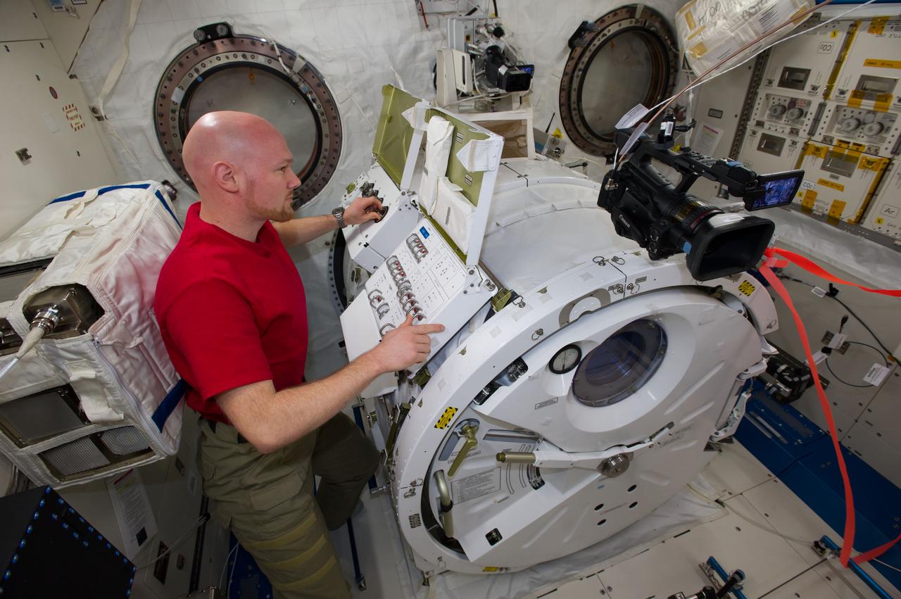
ISS040-E-096122 (18 Aug. 2014) --- In the International Space Station?s Kibo laboratory, European Space Agency astronaut Alexander Gerst, Expedition 40 flight engineer, depressurizes the Kibo airlock in preparation for a series of NanoRacks CubeSat miniature satellite deployments. The first two pairs of nanosatellites are scheduled for deployment on Aug. 19. The Planet Labs Dove satellites that were carried to the station aboard the Orbital Sciences Cygnus commercial cargo craft are being deployed between Aug. 19 and Aug. 25.
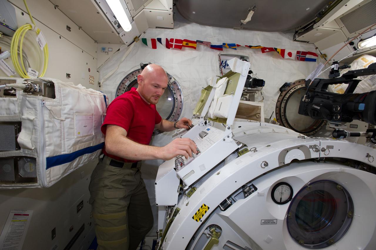
ISS040-E-096126 (18 Aug. 2014) --- In the International Space Station?s Kibo laboratory, European Space Agency astronaut Alexander Gerst, Expedition 40 flight engineer, depressurizes the Kibo airlock in preparation for a series of NanoRacks CubeSat miniature satellite deployments. The first two pairs of nanosatellites are scheduled for deployment on Aug. 19. The Planet Labs Dove satellites that were carried to the station aboard the Orbital Sciences Cygnus commercial cargo craft are being deployed between Aug. 19 and Aug. 25.
Atlantis', Orbiter Vehicle (OV) 104's, remote manipulator system (RMS) releases Gamma Ray Observatory (GRO) during STS-37 deployment. Visible on the GRO as it drifts away from the RMS end effector are the four complement instruments: the Energetic Gamma Ray Experiment (bottom); Imaging Compton Telescope (COMPTEL) (center); Oriented Scintillation Spectrometer Experiment (OSSE) (top); and Burst and Transient Source Experiment (BATSE) (at four corners). GRO's solar array (SA) panels are extended and are in orbit configuration. View was taken through aft flight deck window which reflects some of the crew compartment interior.

iss059e103862 (6/17/2019) --- Photo documentation taken of the JEM Small Satellite Orbital Deployer #11 (J-SSOD #11) micro-satellite deployment mission. SpooQy-1 is a 3-Unit (3U) CubeSat deployed during the J-SSOD #11 mission. SpooQy-1 was developed by the National University of Singapore (NUS).

iss059e104863 (6/17/2019) --- Photo documentation taken of the JEM Small Satellite Orbital Deployer #11 (J-SSOD #11) micro-satellite deployment mission. SpooQy-1 is a 3-Unit (3U) CubeSat deployed during the J-SSOD #11 mission. SpooQy-1 was developed by the National University of Singapore (NUS).

iss047e134134 (5/26/2018) --- NASA astronaut Jeff Williams and European Space Agency (ESA) astronaut Tim Peake during Bigelow Expandable Activity Module (BEAM) deployment. The Bigelow Expandable Activity Module (BEAM) is an experimental expandable capsule that docks with the International Space Station (ISS). After docking, BEAM inflates to roughly 13 feet long and 10.5 feet in diameter to provide a habitable volume where a crew member can enter.

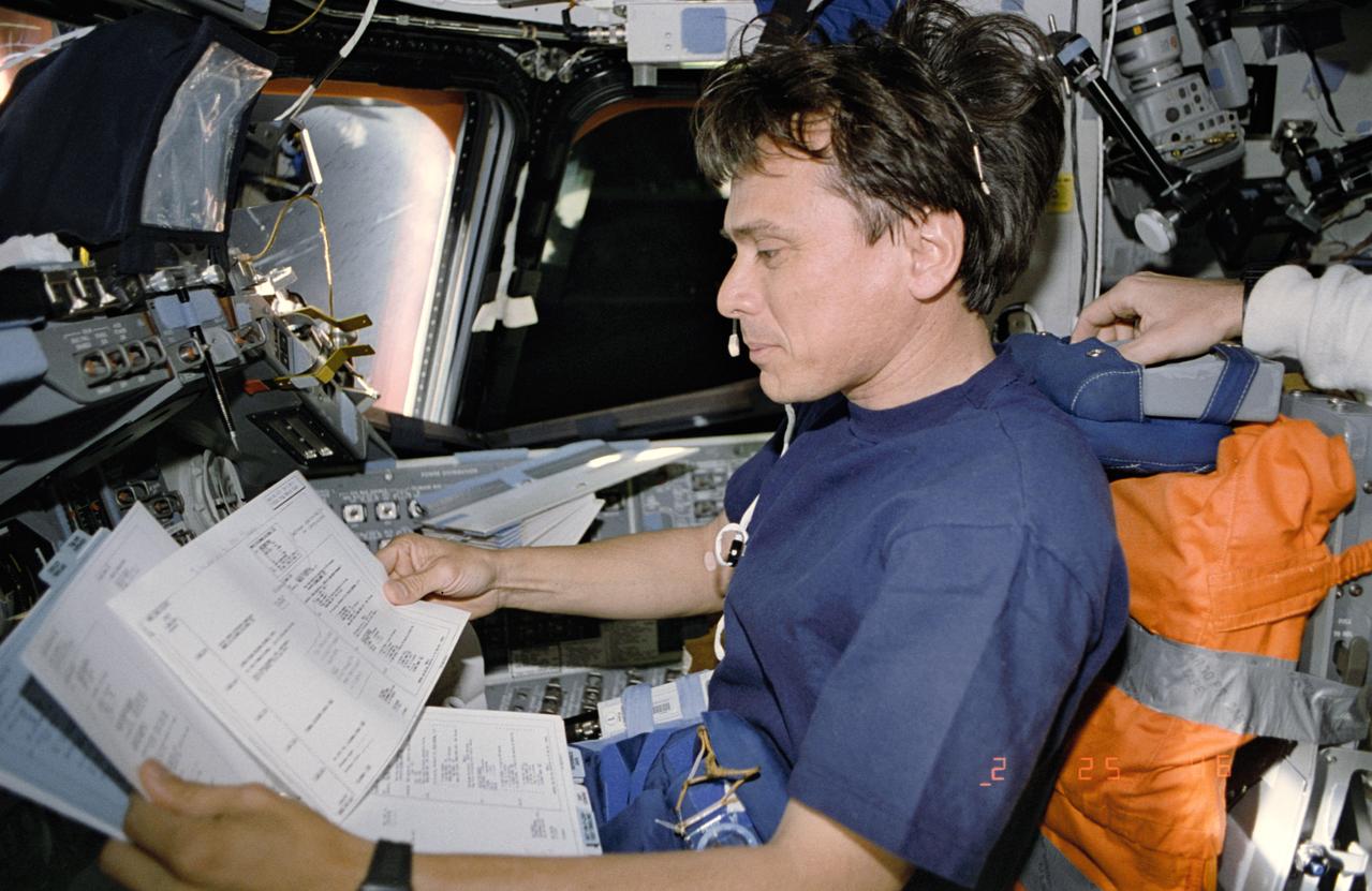
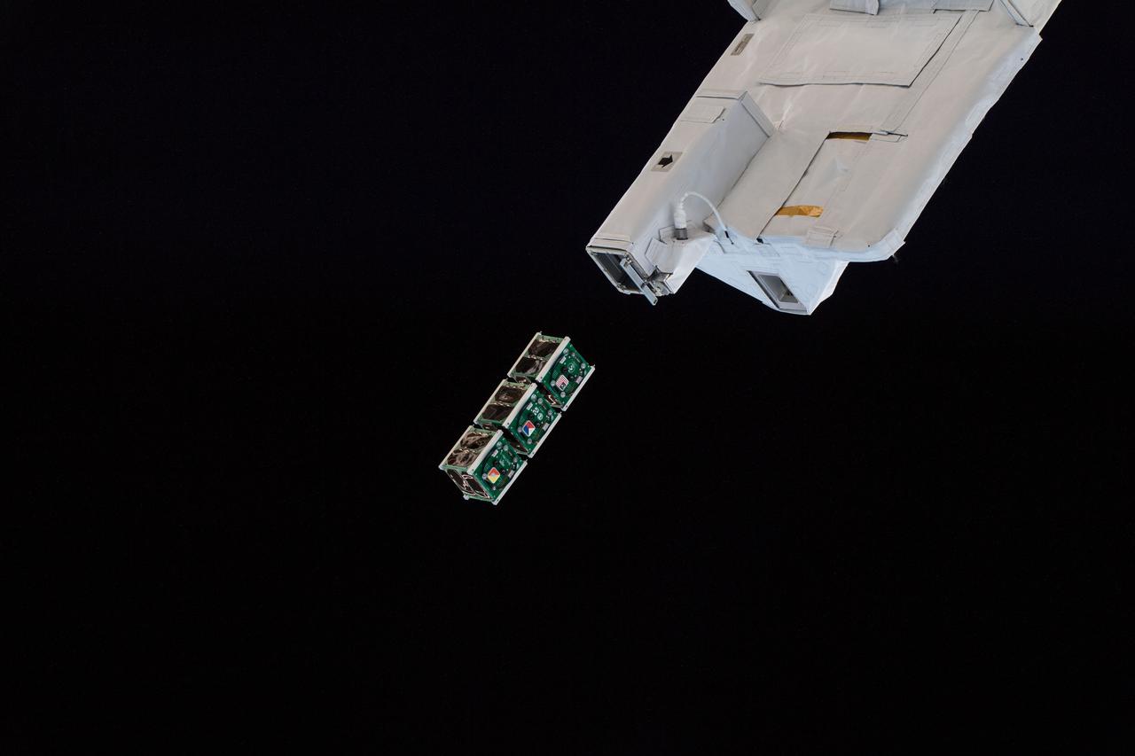
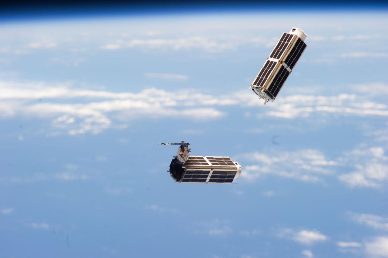
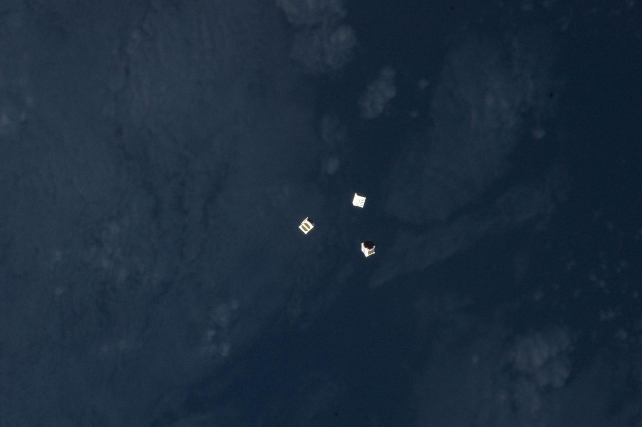
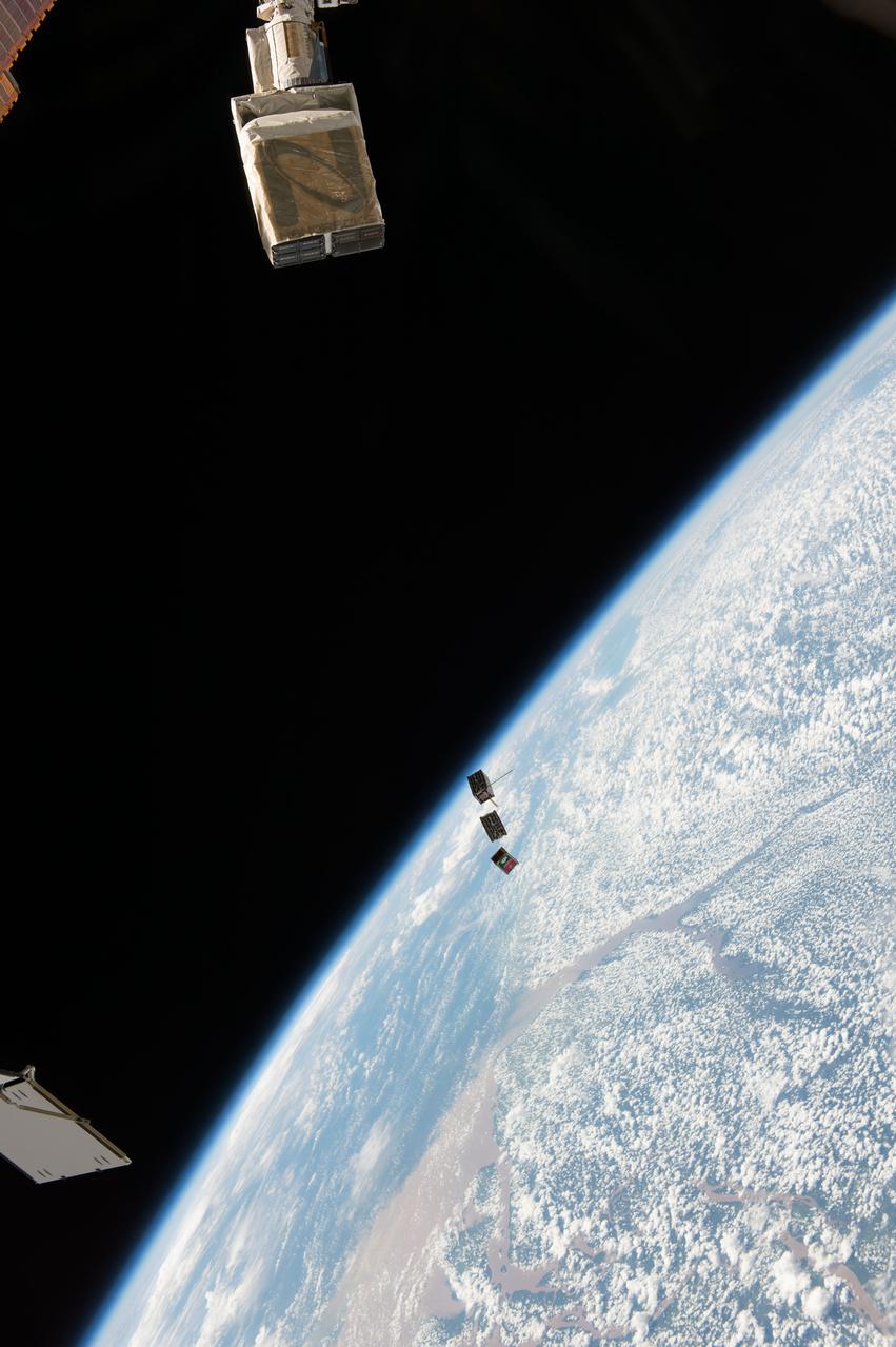
ISS038-E-003872 (19 Nov. 2013) --- Three nanosatellites, known as Cubesats, are deployed from a Small Satellite Orbital Deployer (SSOD) attached to the Kibo laboratory’s robotic arm at 7:10 a.m. (EST) on Nov. 19, 2013. Japan Aerospace Exploration Agency astronaut Koichi Wakata, Expedition 38 flight engineer, monitored the satellite deployment while operating the Japanese robotic arm from inside Kibo. The Cubesats were delivered to the International Space Station Aug. 9, aboard Japan’s fourth H-II Transfer Vehicle, Kounotori-4.
ISS038-E-003874 (19 Nov. 2013) --- Three nanosatellites, known as Cubesats, are deployed from a Small Satellite Orbital Deployer (SSOD) attached to the Kibo laboratory's robotic arm at 7:10 a.m. (EST) on Nov. 19, 2013. Japan Aerospace Exploration Agency astronaut Koichi Wakata, Expedition 38 flight engineer, monitored the satellite deployment while operating the Japanese robotic arm from inside Kibo. The Cubesats were delivered to the International Space Station Aug. 9, aboard Japan's fourth H-II Transfer Vehicle, Kounotori-4.
ISS038-E-003870 (19 Nov. 2013) --- Three nanosatellites, known as Cubesats, are deployed from a Small Satellite Orbital Deployer (SSOD) attached to the Kibo laboratory’s robotic arm at 7:10 a.m. (EST) on Nov. 19, 2013. Japan Aerospace Exploration Agency astronaut Koichi Wakata, Expedition 38 flight engineer, monitored the satellite deployment while operating the Japanese robotic arm from inside Kibo. The Cubesats were delivered to the International Space Station Aug. 9, aboard Japan’s fourth H-II Transfer Vehicle, Kounotori-4.
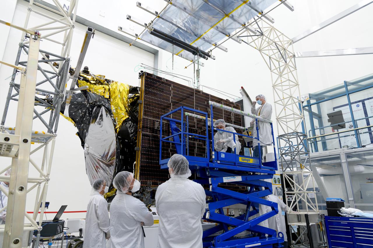
Engineers at NASA's Jet Propulsion Laboratory in Southern California examine one of Psyche's stowed solar arrays prior to a deployment test in the Lab's High Bay 2 clean room in late February 2022. The twin arrays are together about 800 square feet (75 square meters) – the largest ever deployed at JPL. Part of a solar electric propulsion system provided by Maxar Technologies, they will power the spacecraft on its 1.5 billion-mile (2.4 billion-kilometer) journey to the large, metal-rich asteroid Psyche. Only the three center panels on each five-panel, cross-shaped array can be deployed at JPL due to the limitations of the gravity-offload fixture and the opposing direction of rotation of the cross panels. Deployment of the two cross panels was previously performed at Maxar with different equipment. After further spacecraft testing is completed at JPL, the arrays will be removed and returned to Maxar in order to repeat the cross-panel deployments, make any final repairs to the solar cells, and test overall performance. The arrays then get shipped from Maxar to NASA's Kennedy Space Center in Florida, where they will be reintegrated onto the spacecraft in preparation for launch in August 2022. About an hour after launch, Psyche will deploy the arrays sequentially, first unfolding the three lengthwise center panels, then the two cross panels on one wing before repeating the process with the other wing. Each array takes about 7 ½ minutes to unfurl and latch into place. Each array is 37.1 feet (11.3 meters) long and 24 feet (7.3 meters) wide when fully deployed. With arrays deployed on either side of the chassis, the spacecraft is about the size of a singles tennis court: 81 feet long (24.7 meters) and 24 feet (7.3 meters) wide. https://photojournal.jpl.nasa.gov/catalog/PIA25132
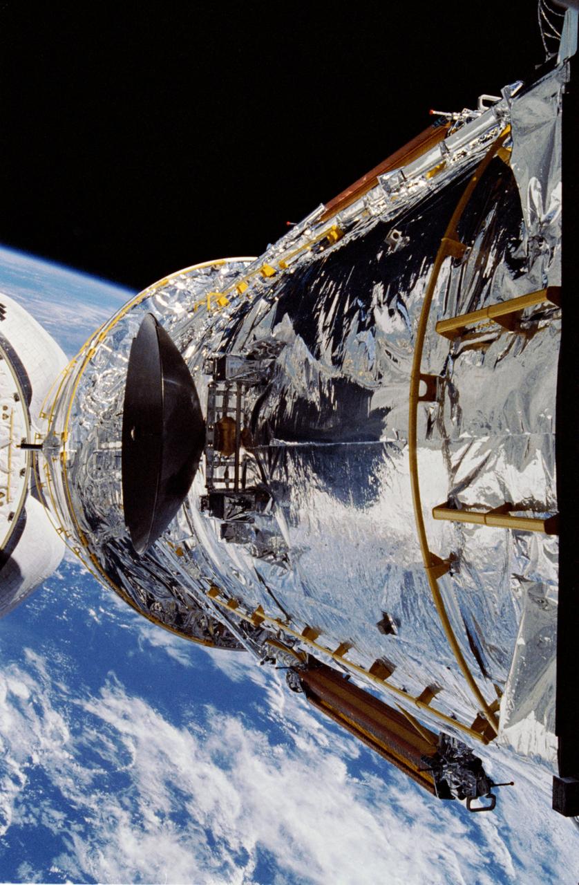
The Hubble Space Telescope (HST) is raised above the payload bay (PLB) in low hover position during STS-31 checkout and pre-deployment procedures aboard Discovery, Orbiter Vehicle (OV) 103. Stowed along the HST Support System Module (SSM) are the high gain antenna (HGA) (center) and the two solar arrays (one either side). In the background are the orbital maneuvering system (OMS) pods and the Earth's surface.
STS054-71-077 (13 Jan 1993) --- The Tracking and Data Relay Satellite (TDRS) quickly moves away from the Space Shuttle Endeavour following deployment on the first day of the six-day mission. Onboard NASA's newest Shuttle for the six-day mission are astronauts John H. Casper, mission commander; Donald R. McMonagle, pilot; and Mario Runco Jr., Gregory J. Harbaugh and Susan J. Helms, mission specialists. The photograph was taken with a 70mm camera.
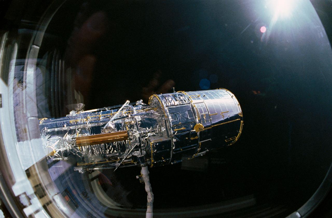
View taken through overhead window W7 aboard Discovery, Orbiter Vehicle (OV) 103, shows the Hubble Space Telescope (HST) grappled by the remote manipulator system (RMS) and held in a 90 degree pitch position against the blackness of space. The solar array (SA) panel (center) and the high gain antennae (HGA) (on either side) are visible along the Support System Module (SSM) forward shell prior to deployment during STS-31.
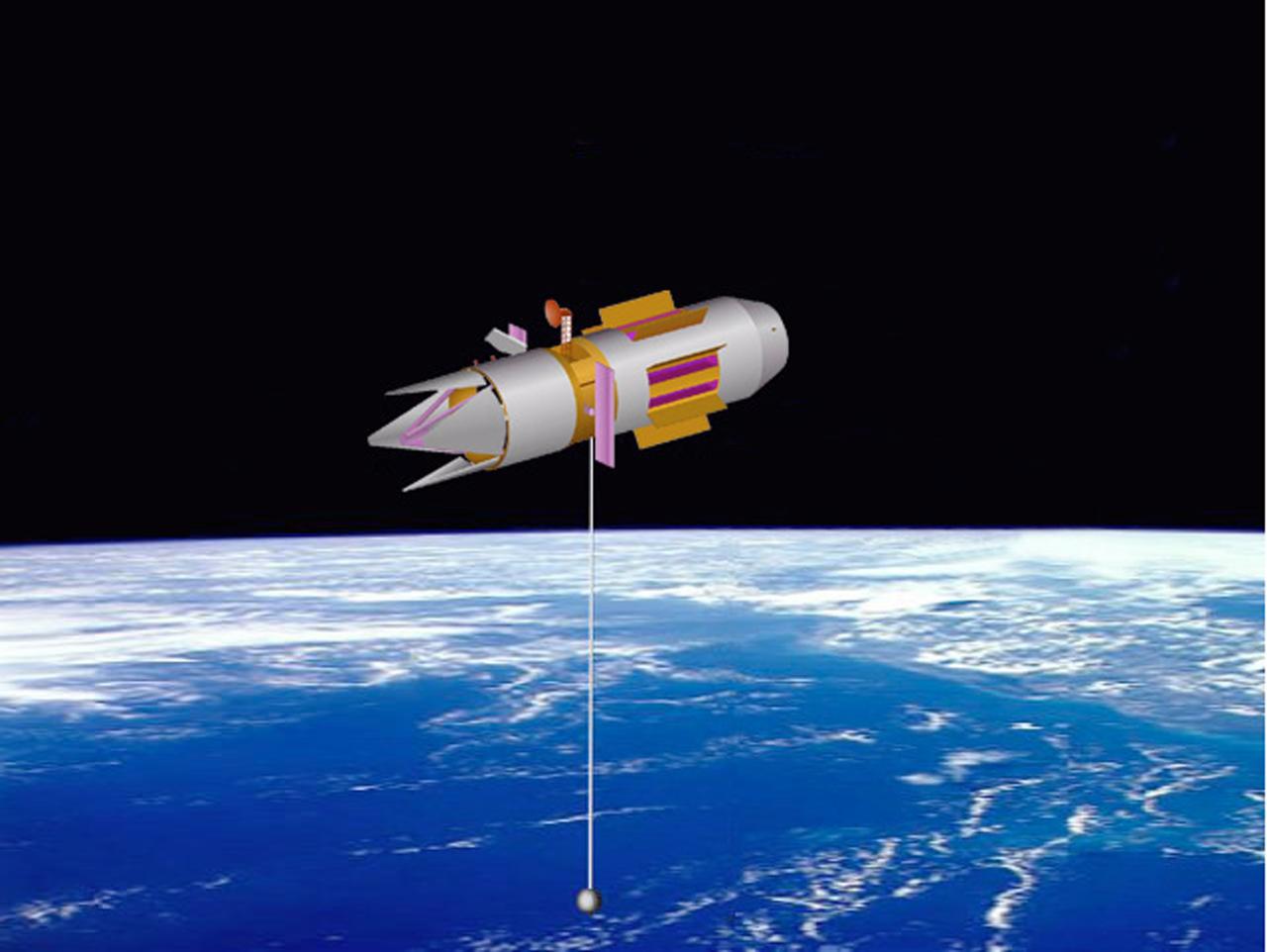
An artist's concept of a space based vehicle using the Propulsive Small Expendable Deployer System (ProSEDS) to generate its thrust to maintain orbit without using a propellant. ProSEDS will obtain thrust as the current flowing through the tether experiences a drag force due to interaction with the Earth's magnetic field. Drag force is coupled mechanically to the stage via the tether, thus lowering the stage's orbital altitude.
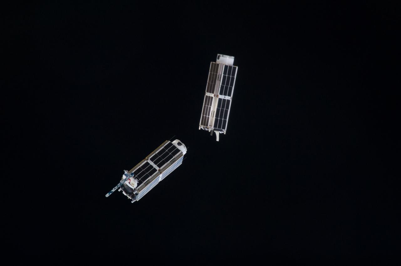
ISS038-E-046579 (13 Feb. 2014) --- A set of NanoRacks CubeSats is photographed by an Expedition 38 crew member after the deployment by the NanoRacks Launcher attached to the end of the Japanese robotic arm. The CubeSats program contains a variety of experiments such as Earth observations and advanced electronics testing.
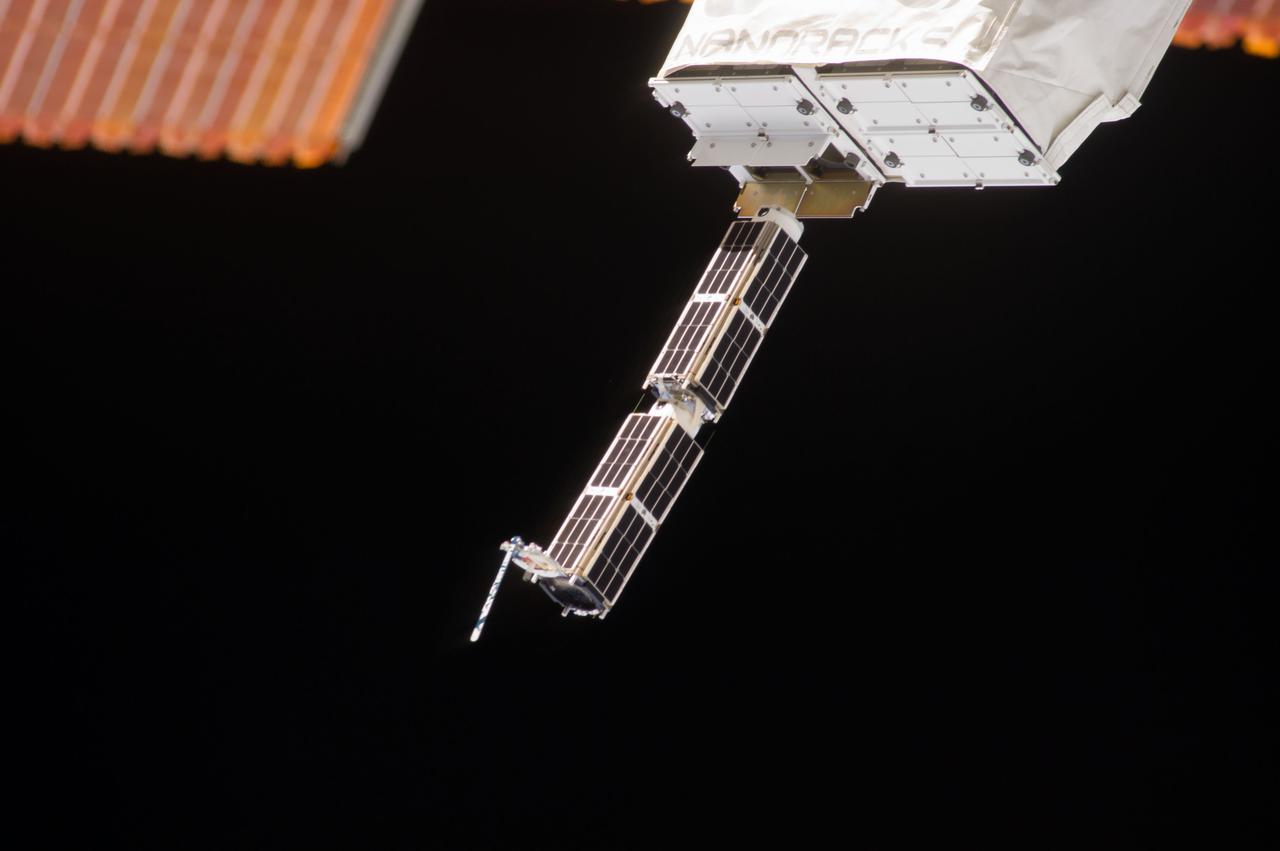
ISS038-E-044889 (11 Feb. 2014) --- The Small Satellite Orbital Deployer (SSOD), in the grasp of the Kibo laboratory robotic arm, is photographed by an Expedition 38 crew member on the International Space Station as it deploys a set of NanoRacks CubeSats. The CubeSats program contains a variety of experiments such as Earth observations and advanced electronics testing.
ISS038-E-044887 (11 Feb. 2014) --- The Small Satellite Orbital Deployer (SSOD), in the grasp of the Kibo laboratory robotic arm, is photographed by an Expedition 38 crew member on the International Space Station as it deploys a set of NanoRacks CubeSats. The CubeSats program contains a variety of experiments such as Earth observations and advanced electronics testing.
ISS038-E-046586 (13 Feb. 2014) --- A set of NanoRacks CubeSats is photographed by an Expedition 38 crew member after the deployment by the NanoRacks Launcher attached to the end of the Japanese robotic arm. The CubeSats program contains a variety of experiments such as Earth observations and advanced electronics testing.
AS16-116-18578 (21 April 1972) --- Astronaut John W. Young, commander of the Apollo 16 lunar landing mission, works at the Lunar Roving Vehicle (LRV) just prior to deployment of the Apollo Lunar Surface Experiments Package (ALSEP) during the first extravehicular activity (EVA) on April 21, 1972. Note the Ultraviolet (UV) Camera/Spectrometer to the right of the Lunar Module (LM) ladder. Also, note the pile of protective/thermal foil under the U.S. flag on the LM which the astronauts pulled away to get to the Modular Equipment Storage Assembly (MESA) bay. While astronauts Young and Charles M. Duke Jr., lunar module pilot; descended in the Apollo 16 LM "Orion" to explore the Descartes highlands landing site on the moon, astronaut Thomas K. Mattingly II, command module pilot, remained with the Command and Service Modules (CSM) "Casper" in lunar orbit.
iss050e017076 (12/19/2016) --- A view after Japanese Experiment Module Remote Manipulator System (JEMRMS) Small Satellite Deployment called Space Tethered Autonomous Robotic satellite (STARS-C).
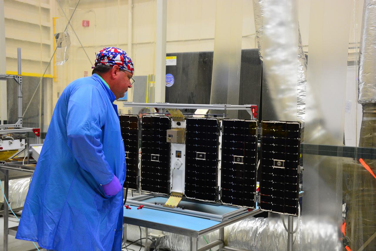
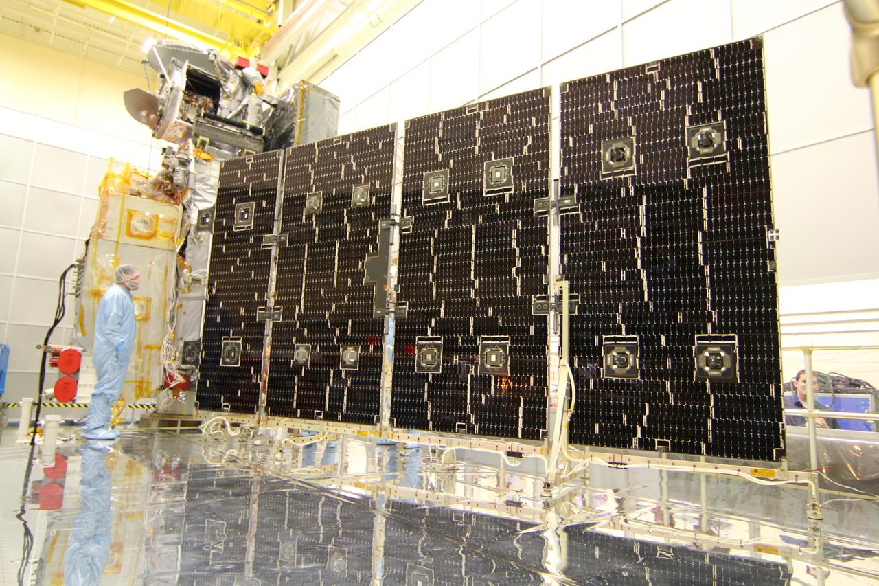
Inside Building 1555 at Vandenberg Air Force Base in California, solar panels for one of eight NASA's Cyclone Global Navigation Satellite System (CYGNSS) spacecraft has been deployed for illumination testing. Processing activities will prepare the spacecraft for launch aboard an Orbital ATK Pegasus XL rocket. When preparations are completed at Vandenberg, the rocket will be transported to NASA's Kennedy Space Center in Florida attached to the Orbital ATK L-1011 carrier aircraft within its payload fairing. CYGNSS will launch on the Pegasus XL rocket from the Skid Strip at Cape Canaveral Air Force Station. CYGNSS will make frequent and accurate measurements of ocean surface winds throughout the life cycle of tropical storms and hurricanes. The data that CYGNSS provides will enable scientists to probe key air-sea interaction processes that take place near the core of storms, which are rapidly changing and play a critical role in the beginning and intensification of hurricanes.
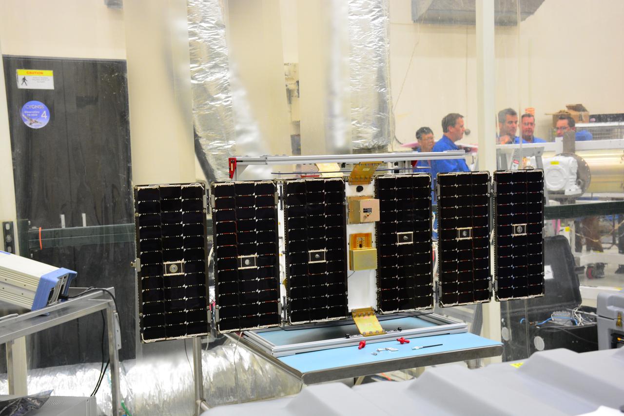
Inside Building 1555 at Vandenberg Air Force Base in California, solar panels for one of eight NASA's Cyclone Global Navigation Satellite System (CYGNSS) spacecraft has been deployed for illumination testing. Processing activities will prepare the spacecraft for launch aboard an Orbital ATK Pegasus XL rocket. When preparations are completed at Vandenberg, the rocket will be transported to NASA's Kennedy Space Center in Florida attached to the Orbital ATK L-1011 carrier aircraft within its payload fairing. CYGNSS will launch on the Pegasus XL rocket from the Skid Strip at Cape Canaveral Air Force Station. CYGNSS will make frequent and accurate measurements of ocean surface winds throughout the life cycle of tropical storms and hurricanes. The data that CYGNSS provides will enable scientists to probe key air-sea interaction processes that take place near the core of storms, which are rapidly changing and play a critical role in the beginning and intensification of hurricanes.
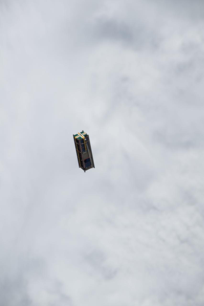
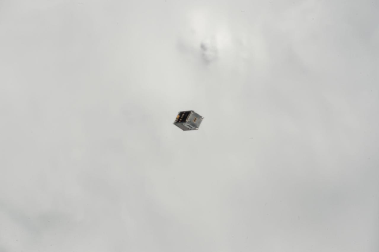
iss053e235256 (11/20/2017) --- A view of the Dellingr/RBLE Satellite deployment from the NanoRacks CubeSate Deployer Number 13 aboard the International Space Station (ISS). Dellingr/RBLE expands understanding of space weather risk by establishing baseline estimates of magnetic variation and particle fluxes in the exosphere. The instrument also observes cause and effect relationships between solar events and Earth’s atmosphere, which advances fundamental understanding of electromagnetic dynamics in the space environment.
iss053e235231 (11/20/2017) --- A view of the Dellingr/RBLE Satellite deployment from the NanoRacks CubeSate Deployer Number 13 aboard the International Space Station (ISS). Dellingr/RBLE expands understanding of space weather risk by establishing baseline estimates of magnetic variation and particle fluxes in the exosphere. The instrument also observes cause and effect relationships between solar events and Earth’s atmosphere, which advances fundamental understanding of electromagnetic dynamics in the space environment.
iss053e235238(11/20/2017) --- A view of the Dellingr/RBLE Satellite deployment from the NanoRacks CubeSate Deployer Number 13 aboard the International Space Station (ISS). Dellingr/RBLE expands understanding of space weather risk by establishing baseline estimates of magnetic variation and particle fluxes in the exosphere. The instrument also observes cause and effect relationships between solar events and Earth’s atmosphere, which advances fundamental understanding of electromagnetic dynamics in the space environment.
iss053e235232 (11/20/2017) --- A view of the Dellingr/RBLE Satellite deployment from the NanoRacks CubeSate Deployer Number 13 aboard the International Space Station (ISS). Dellingr/RBLE expands understanding of space weather risk by establishing baseline estimates of magnetic variation and particle fluxes in the exosphere. The instrument also observes cause and effect relationships between solar events and Earth’s atmosphere, which advances fundamental understanding of electromagnetic dynamics in the space environment.

iss059e104298 (6/17/2019) --- Photo documentation taken of the JEM Small Satellite Orbital Deployer #11 (J-SSOD #11) micro-satellite deployment mission. J-SSOD#11 deploys the Joint Global Multi Nation Birds, known as the BIRDS-3 Project, which is a constellation of three 1U CubeSats developed by Japan, Nepal and Sri Lanka . The satellites, named Uguisu, Raavana-1, and NepaliSat-1, were released into Earth orbit for technology demonstrations.