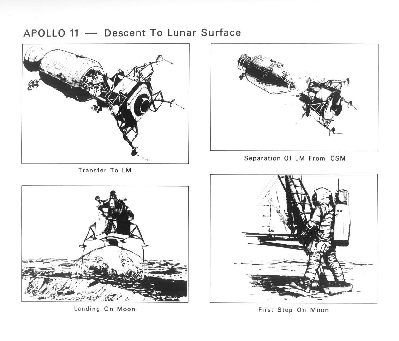
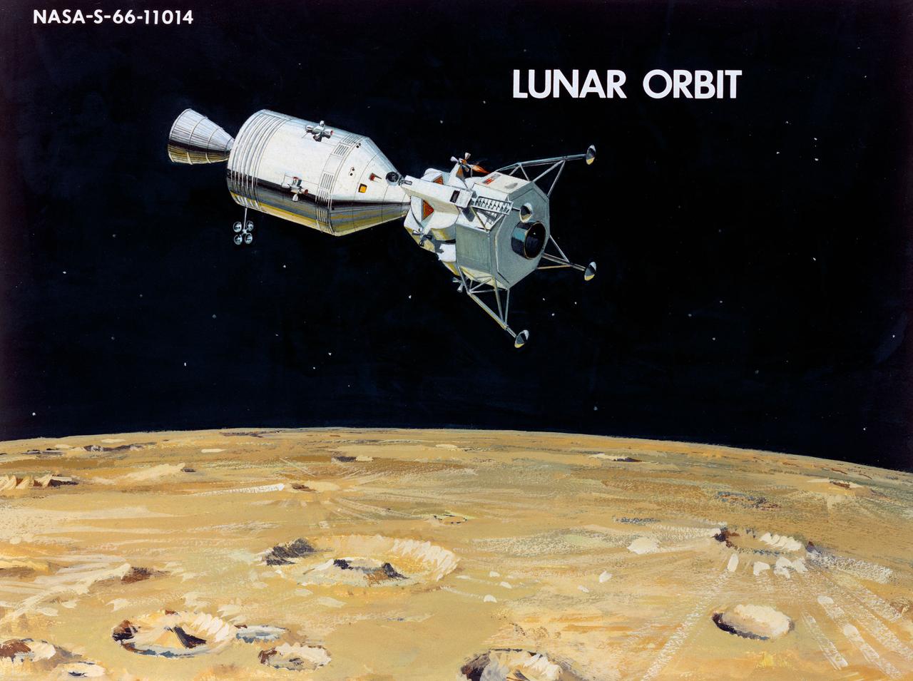
The Apollo 11 mission launched from the Kennedy Space Center (KSC) in Florida via the Marshall Space Flight Center (MSFC) developed Saturn V launch vehicle on July 16, 1969 and safely returned to Earth on July 24, 1969. Aboard the space craft were astronauts Neil A. Armstrong, commander; Michael Collins, Command Module (CM) pilot; and Edwin E. (Buzz) Aldrin Jr., Lunar Module (LM) pilot. With the success of Apollo 11, the national objective to land men on the Moon and return them safely to Earth had been accomplished. These sketches illustrate the steps taken in going from lunar orbit onto the Moon’s surface. Apollo 11 commander, Neil Armstrong and LM pilot Edwin Aldrin transferred from the CM to the LM and the LM separated. Firing the descent stage engine in retrothrust slowed the LM and put it on the let down trajectory. Near the Lunar surface, the engine was used to lower the craft slowly to the surface. After a checkout of systems and depressurization of the LM cabin, the hatch was opened for Armstrong’s climb down the ladder to the Moon’s soil.
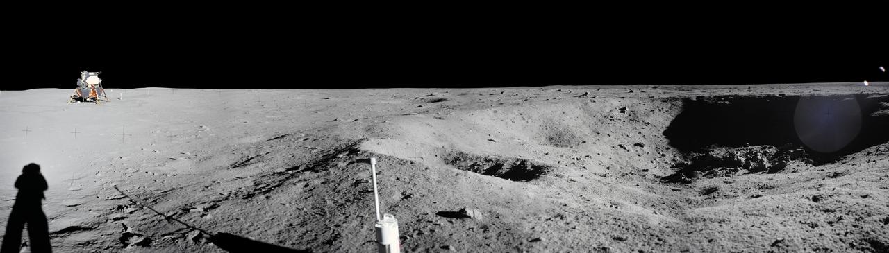
jsc2008e040725 - Panorama view of Apollo 11 Lunar surface photos taken by Astronaut Neil Armstrong at Tranquility Base of a crater Armstrong noted during the Lunar Module descent. The panoramas were built by combining Apollo 11 images starting with frame AS11-40-5954 through end frame AS11-40-5961. The panoramic images received minimal retouching by NASA imagery specialists, including the removal of lens flares that were problematic in stitching together the individual frames and blacking out the sky to the lunar horizon. These adjustments were made based on observations of the Moon walkers who reported that there are no stars visible in the sky due to the bright lunar surface reflection of the Sun.
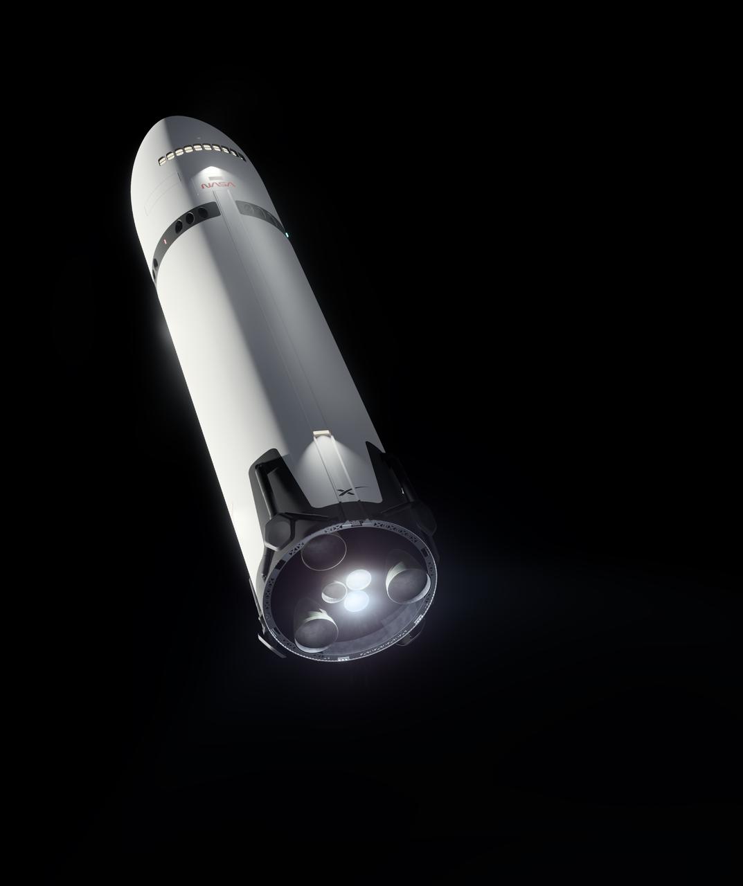
This artist’s concept portrays SpaceX’s Starship Human Landing System (HLS) with two Raptor engines lit, performing a braking burn prior to its Moon landing. The burn will occur after Starship HLS departs low lunar orbit to reduce the lander’s velocity prior to final descent to the lunar surface. NASA is working with SpaceX to develop Starship HLS to carry astronauts from lunar orbit to the Moon’s surface and back for Artemis III and Artemis IV as part of the agency’s Artemis campaign.
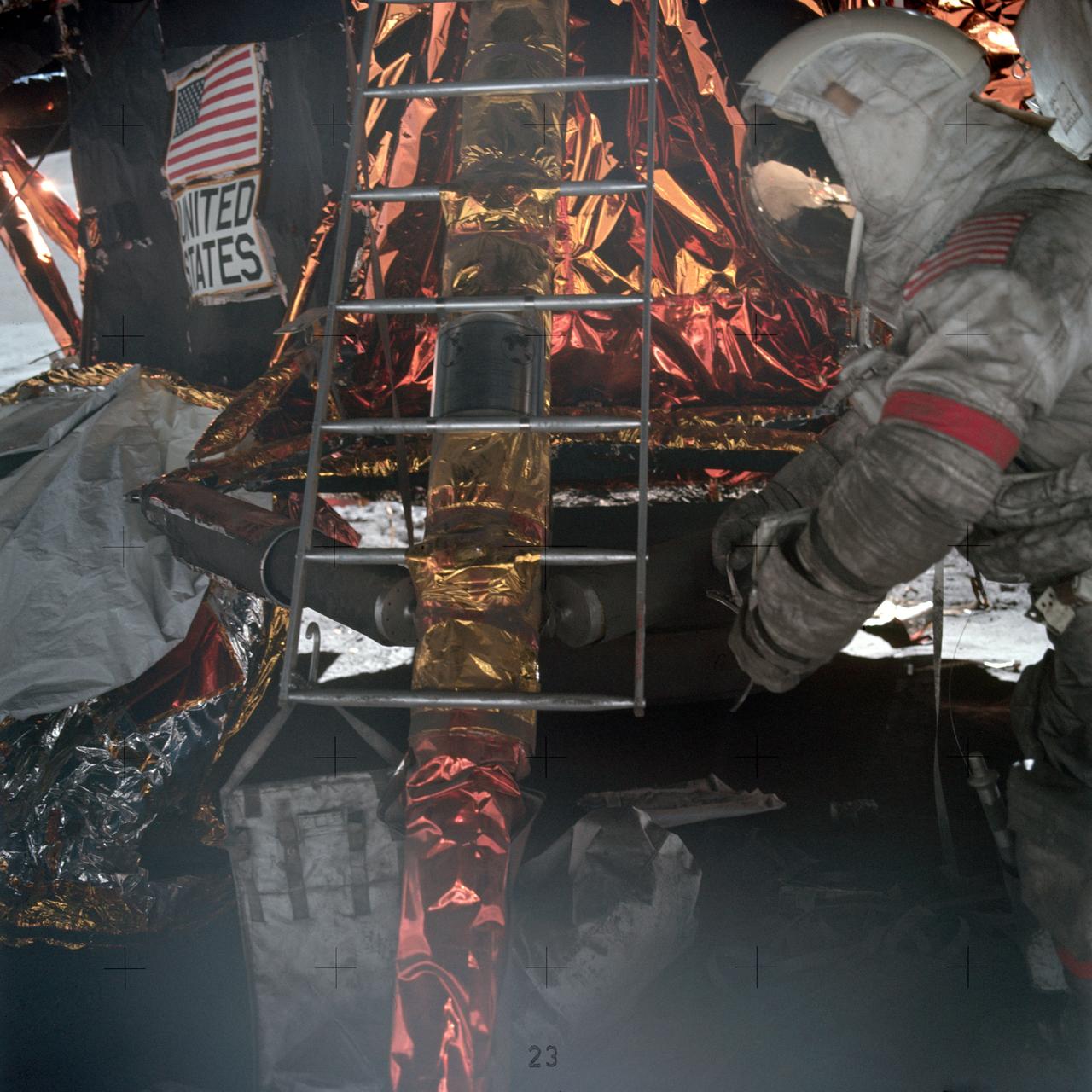
Astronaut Eugene A. Cernan, Apollo 17 commander, prepares to mount ladder to lunar module ascent stage. Note the plaque attached to the ladder which will be left with the descent stage when the mission lifts off from the lunar surface.
S69-33765 (12 May 1969) --- Artist's concept depicting the firing of the Apollo 10 Lunar Module descent engine for 42 seconds to propel "Snoopy" back into a higher lunar orbit for rendezvous and docking with the Command and Service Modules. Earlier, the LM descent engine will be fired for 27 seconds to take astronauts Thomas P. Stafford, Apollo 10 commander; and Eugene A. Cernan, lunar module pilot, to within 10 miles of the moon's surface. Astronauts John W. Young, command module pilot, will remain in the Command Module, "Charlie Brown," in lunar orbit. Developed by TRW's Systems Group at Redondo Beach, California, under Grumman subcontract, the throttleable descent engine will be used to soft land the LM on the lunar surface during Apollo 11 and subsequent Apollo missions.

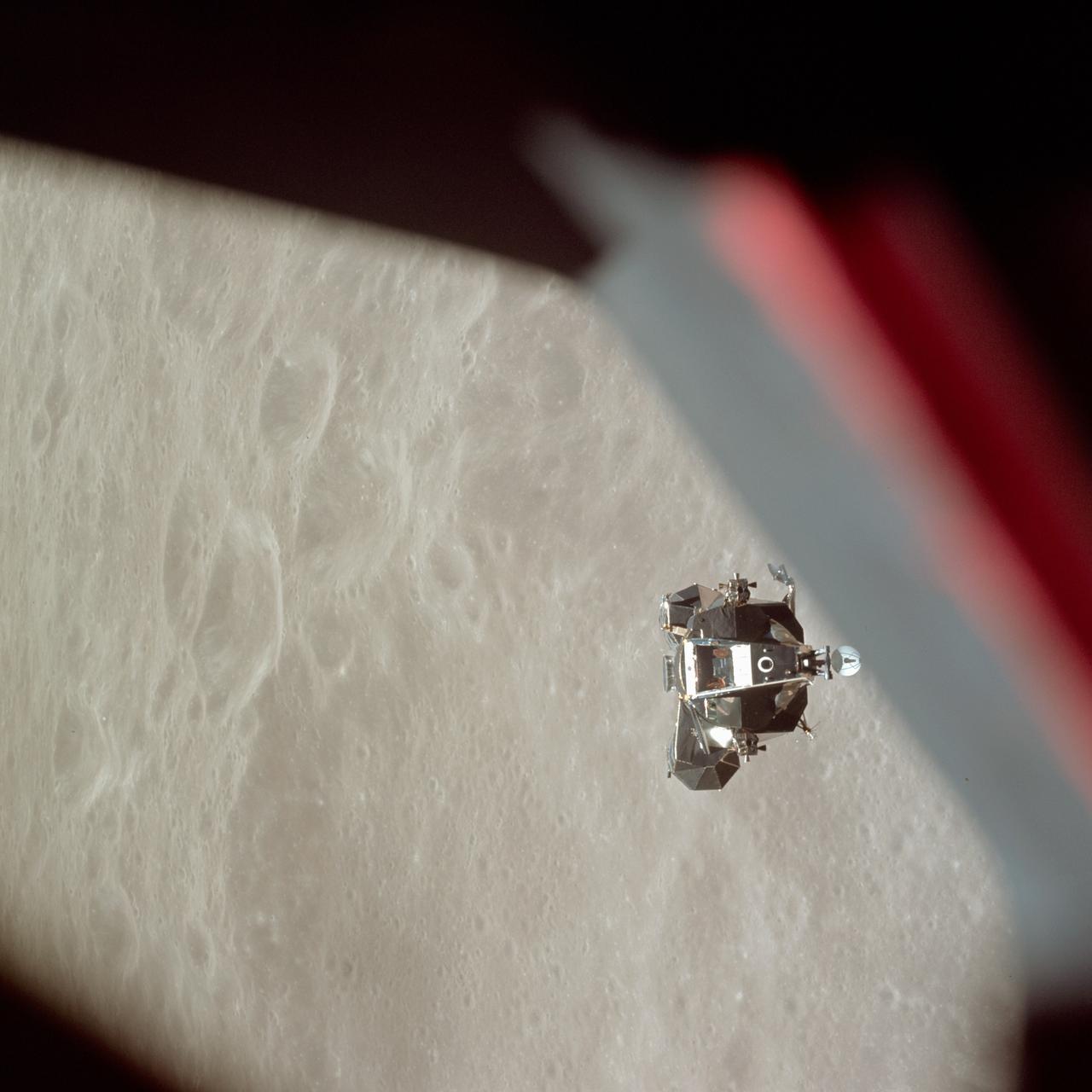
AS11-44-6584 (20 July 1969) --- View of Apollo 11 Lunar Module (LM). This image was taken during separation of the LM and the Command Module during and the LM;s descent to the lunar surface. Blackness of space in background. Film Type: S0-368 color taken with a 250mm lens. Photo credit: NASA
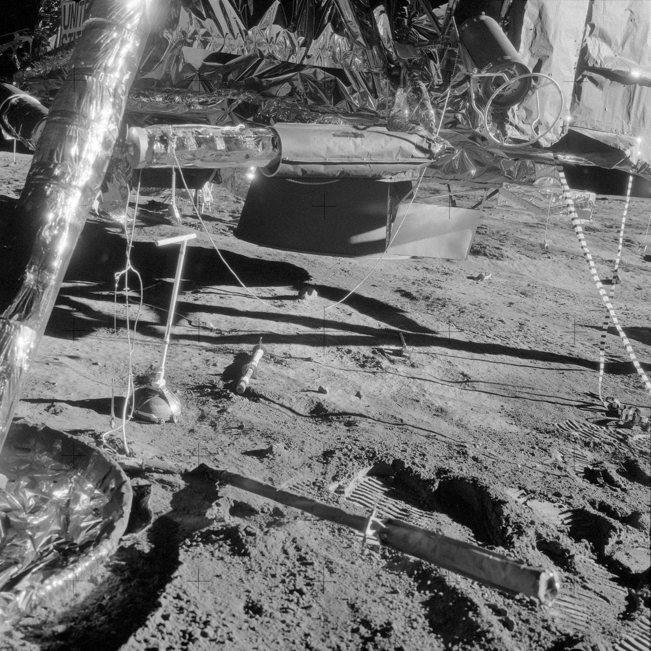
AS12-48-7034 (19 Nov. 1969) --- A close-up view of a portion of quadrant II of the descent stage of the Apollo 12 Lunar Module (LM), photographed during the Apollo 12 extravehicular activity (EVA). At lower left is the LM's Y footpad. The empty Radioisotope Thermoelectric Generator (RTG) fuel cask is at upper right. The fuel capsule has already been removed and placed in the RTG. The RTG furnishes power for the Apollo Lunar Surface Experiments Package (ALSEP) which the Apollo 12 astronauts deployed on the moon. The LM's descent engine skirt is in the center background. The rod-like object protruding out from under the footpad is a lunar surface sensing probe. Astronaut Richard F. Gordon Jr., command module pilot, remained with the Command and Service Modules (CSM) in lunar orbit while astronauts Charles Conrad Jr., commander; and Alan L. Bean, lunar module pilot, descended in the LM to explore the moon.
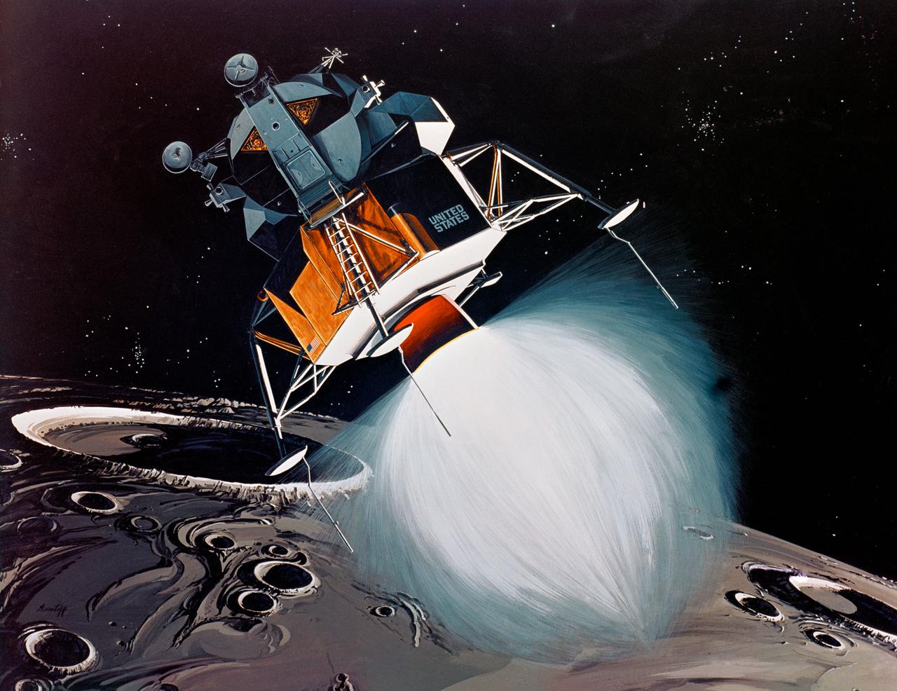
S69-39011 (July 1969) --- TRW Incorporated's artist concept depicting the Apollo 11 Lunar Module (LM) descending to the surface of the moon. Inside the LM will be astronauts Neil A. Armstrong, commander, and Edwin E. Aldrin Jr., lunar module pilot. Astronaut Michael Collins, command module pilot, will remain with the Command and Service Modules (CSM) in lunar orbit. TRW's LM descent engine will brake Apollo 11's descent to the lunar surface. The throttle-able rocket engine will be fired continuously the last 10 miles of the journey to the moon, slowing the LM to a speed of two miles per hour at touchdown. TRW Incorporated designed and built the unique engine at Redondo Beach, California under subcontract to the Grumman Aircraft Engineering Corporation, Bethpage, New York, the LM prime contractor.
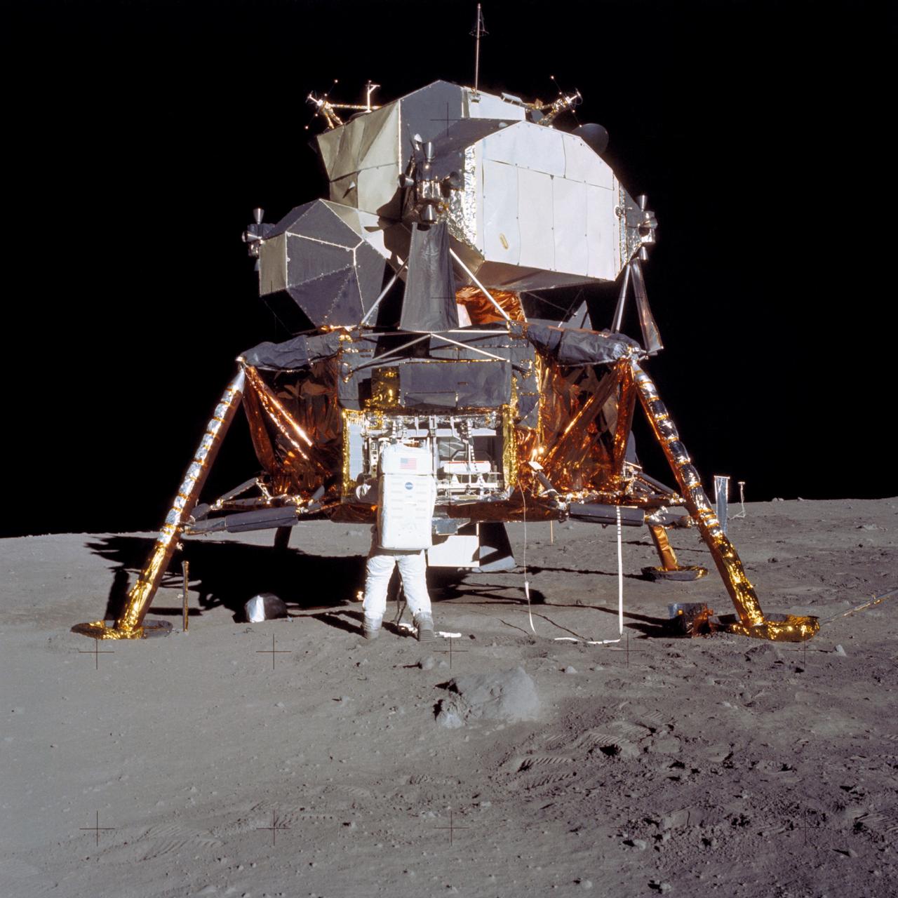
JOHNSON SPACE CENTER, HOUSTON, TEXAS - Man's first landing on the Moon was accomplished at 4:17 p.m. today as Lunar Module "Eagle" touched down gently on the Sea of Tranquility on the east side of the Moon. Astronaut Edwin E. Aldrin Jr., Lunar Module Pilot, removes scientific experiment packages from a stowage area in the Lunar Module's descent stage. Left behind on the lunar surface by Aldrin and Neil A. Armstrong, Apollo 11 commander, were a Passive Seismic Experiments Package and a Laser-Ranging Retro-Reflector.
AS11-40-5927 (20 July 1969) --- Astronaut Edwin E. Aldrin Jr., lunar module pilot, prepares to deploy the Early Apollo Scientific Experiments Package (EASEP) during the Apollo 11 lunar surface extravehicular activity (EVA). Astronaut Neil A. Armstrong, commander, took this picture with a 70mm lunar surface camera. During flight the EASEP is stowed in the Lunar Module's (LM) scientific equipment bay at the left year quadrant of the descent stage looking forward. Aldrin is removing the EASEP from its stowed position. Photo credit: NASA
AS10-34-5112 (26 May 1969) --- The ascent stage of the Apollo 10 Lunar Module (LM) is photographed from the Command Module prior to docking in lunar orbit. The LM is approaching the Command and Service Modules from below. The LM descent stage had already been jettisoned. The lunar surface in the background is near, but beyond the eastern limb of the moon as viewed from Earth (about 120 degrees east longitude). The red/blue diagonal line is the spacecraft window.
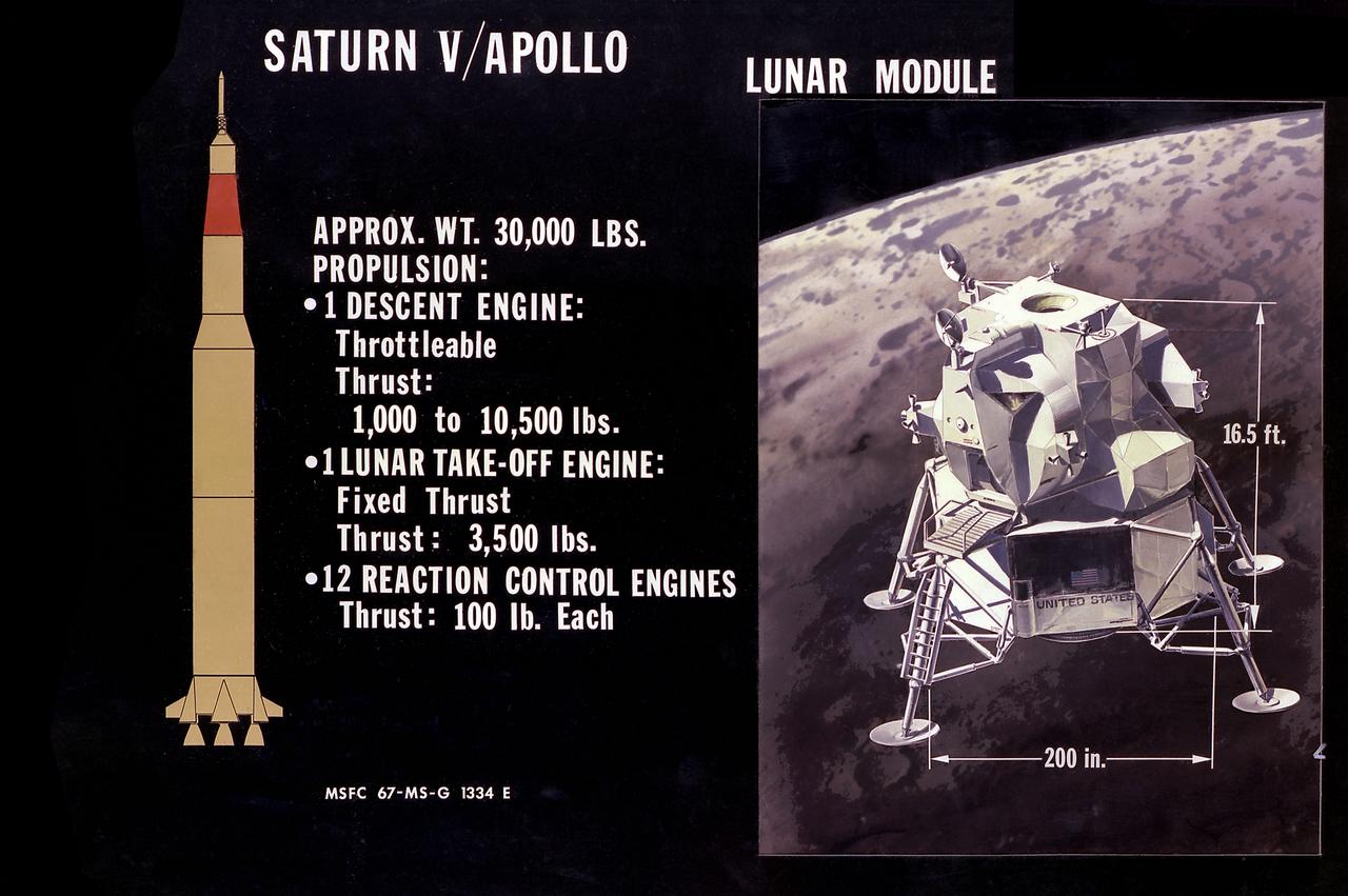
This illustration is the Lunar Module (LM) configuration. The LM was a two part spacecraft. Its lower or descent stage had the landing gear, engines, and fuel needed for the landing. When the LM blasted off the Moon, the descent stage served as the launching pad for its companion ascent stage, which was also home for the two astronauts on the surface of the Moon. The LM was full of gear with which to communicate, navigate, and rendezvous. It also had its own propulsion system, and an engine to lift it off the Moon and send it on a course toward the orbiting Command Module.
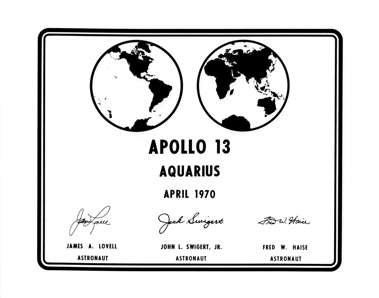
S70-34685 (April 1970) --- A photographic replica of the plaque which the Apollo 13 astronauts will leave behind on the moon during their lunar landing mission. Astronauts James A. Lovell Jr., commander; and Fred W. Haise Jr., lunar module pilot, will descend to the lunar surface in the Lunar Module (LM) "Aquarius". Astronaut John L. Swigert Jr., command module pilot, will remain with the Command and Service Modules (CSM) in lunar orbit. The plaque will be attached to the ladder of the landing gear strut on the LM?s descent stage. Commemorative plaques were also left on the moon by the Apollo 11 and Apollo 12 astronauts.
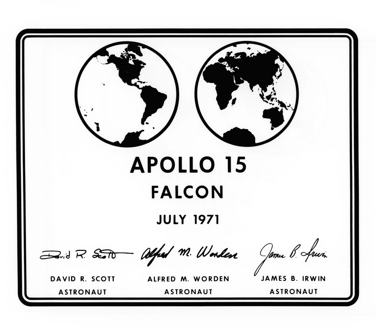
S71-39357 (July 1971) --- A photographic replica of the plaque which the Apollo 15 astronauts will leave behind on the moon during their lunar landing mission. Astronauts David R. Scott, commander; and James B. Irwin, lunar module pilot; will descend to the lunar surface in the Lunar Module (LM) "Falcon". Astronaut Alfred M. Worden, command module pilot, will remain with the Command and Service Modules (CSM) in lunar orbit. The seven by nine inch stainless steel plaque will be attached to the ladder on the landing gear strut on the LM's descent stage. Commemorative plaques were also left on the moon by the Apollo 11, Apollo 12 and Apollo 14 astronauts.
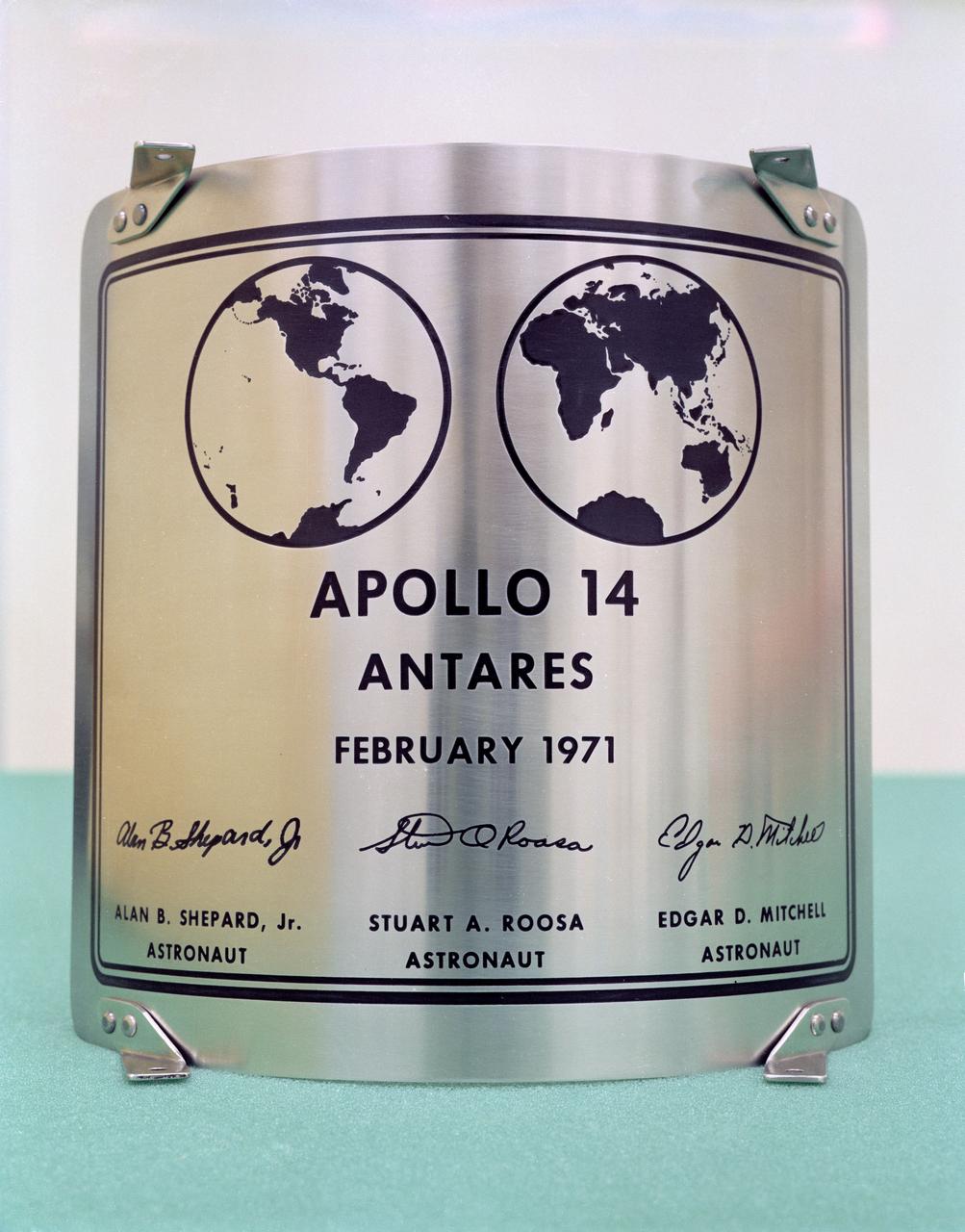
S71-16637 (January 1971) --- A close-up view of the plaque which the Apollo 14 astronauts will leave behind on the moon during their lunar landing mission. Astronauts Alan B. Shepard Jr., commander, and Edgar D. Mitchell, lunar module pilot, will descend to the lunar surface in the Lunar Module (LM) "Antares". Astronaut Stuart A. Roosa, command module pilot, will remain with the Command and Service Modules (CSM) in lunar orbit. The seven by nine inch stainless steel plaque will be attached to the ladder on the landing gear strut on the LM's descent stage. Commemorative plaques were also left on the moon by the Apollo 11 and Apollo 12 astronauts.
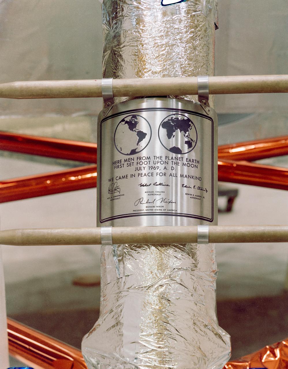
S69-38749 (July 1969) --- Close-up view of the plaque which the Apollo 11 astronauts will leave behind on the moon in commemoration of the historic event. The plaque is made of stainless steel measuring nine by seven and five-eighths inches, and one-sixteenth inch thick. The plaque will be attached to the ladder on the landing gear strut on the descent stage of the Apollo 11 Lunar Module (LM). Covering the plaque during flight will be a thin sheet of stainless steel which will be removed on the lunar surface.
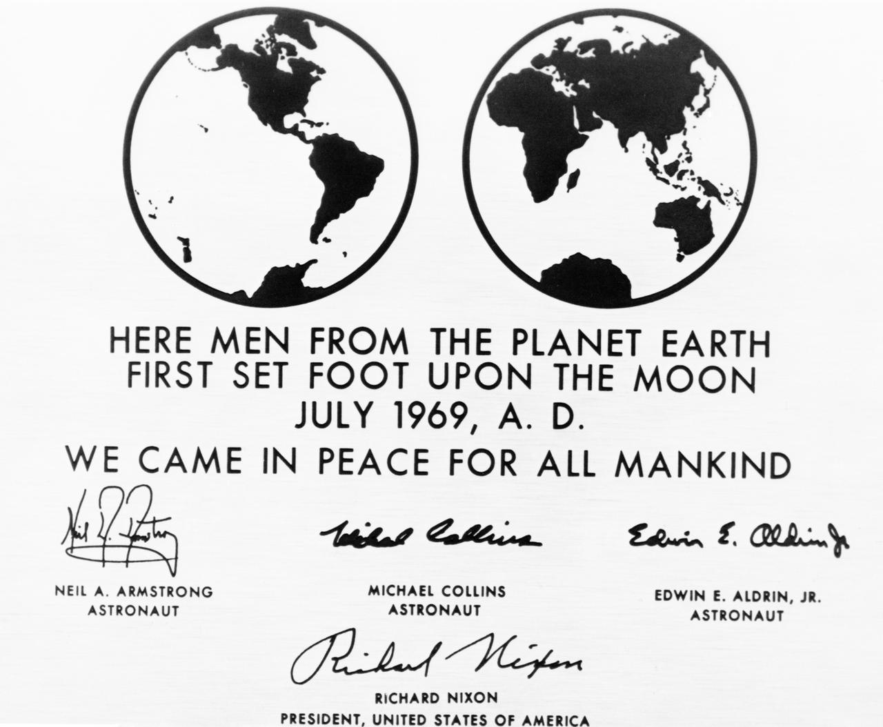
S69-39334 (July 1969) --- This is a replica of the plaque which the Apollo 11 astronauts will leave behind on the moon in commemoration of the historic event. The plaque is made of stainless steel, measuring nine by seven and five-eighths inches, and one-sixteenth inch thick. The plaque will be attached to the ladder on the landing gear strut on the descent stage of the Apollo 11 Lunar Module (LM). Covering the plaque during the flight will be a thin sheet of stainless steel which will be removed on the lunar surface.
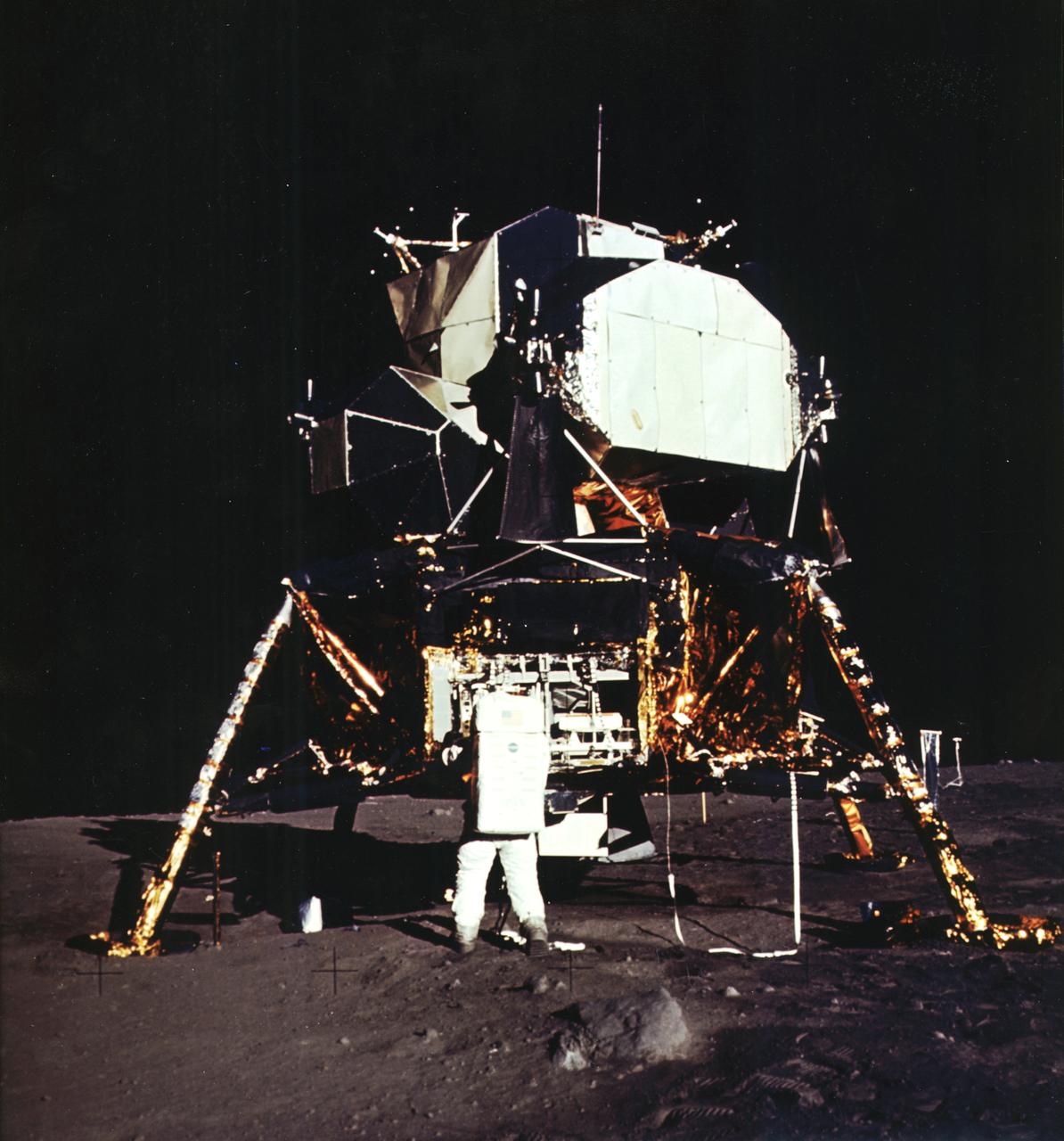
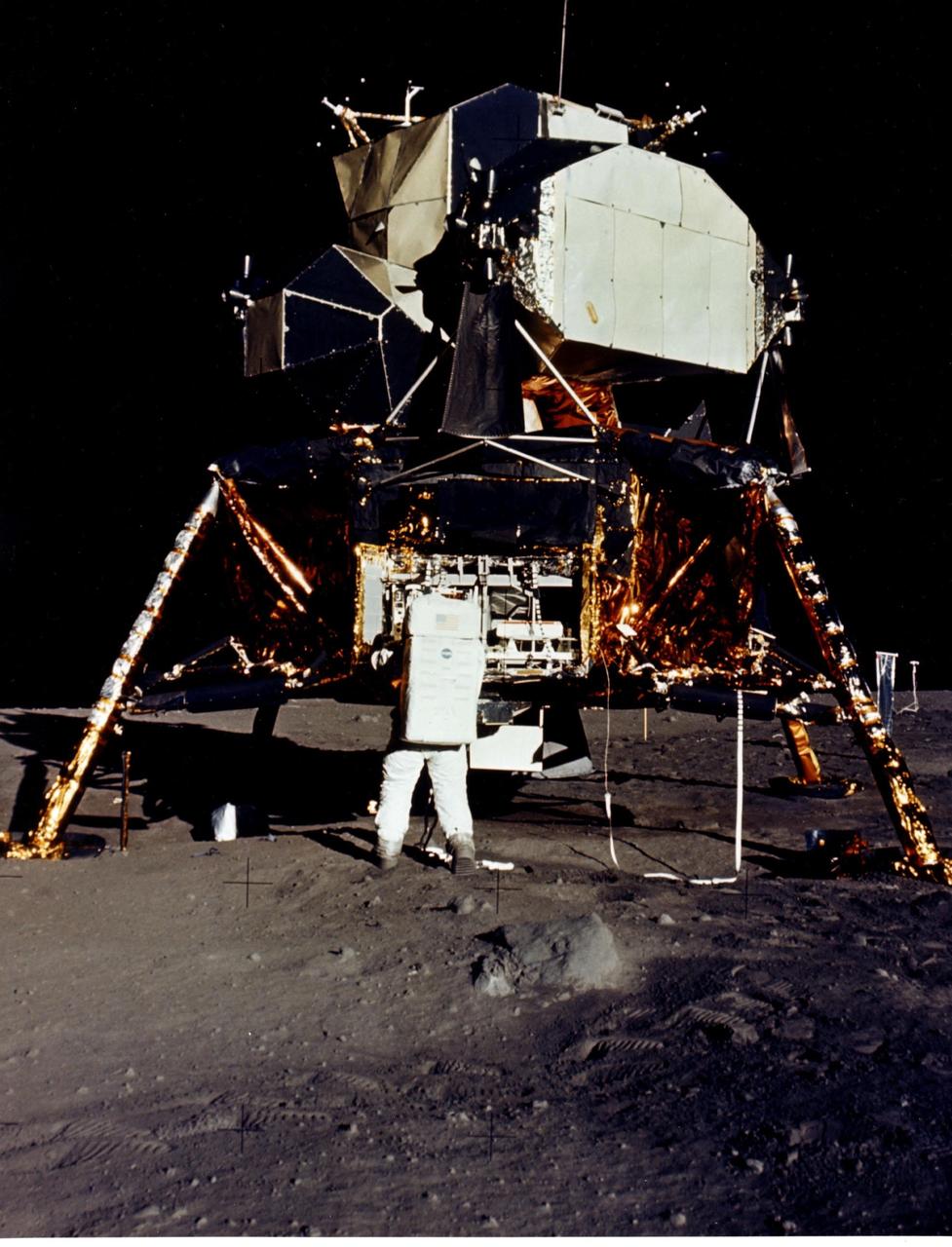
The first manned lunar landing mission, Apollo 11, launched from the Kennedy Space Center (KSC) in Florida via the Marshall Space Flight Center (MSFC) developed Saturn V launch vehicle on July 16, 1969 and safely returned to Earth on July 24, 1969. Aboard the space craft were astronauts Neil A. Armstrong, commander; Michael Collins, Command Module (CM) pilot; and Edwin E. (Buzz) Aldrin Jr., Lunar Module (LM) pilot. The CM, piloted by Michael Collins, remained in a parking orbit around the Moon while the LM, named “Eagle’’, carrying astronauts Armstrong and Aldrin, landed on the Moon in the Sea of Tranquility. The LM was a two part spacecraft. Its lower or descent stage had the landing gear, engines, and fuel needed for the landing. When the LM blasted off the Moon, the descent stage served as the launching pad for its companion ascent stage, which was also home for the two astronauts on the surface of the Moon. The LM was full of gear with which to communicate, navigate, and rendezvous. It also had its own propulsion system, and an engine to lift it off the Moon and send it on a course toward the orbiting CM. Aldrin is pictured here next to the LM on the lunar surface.
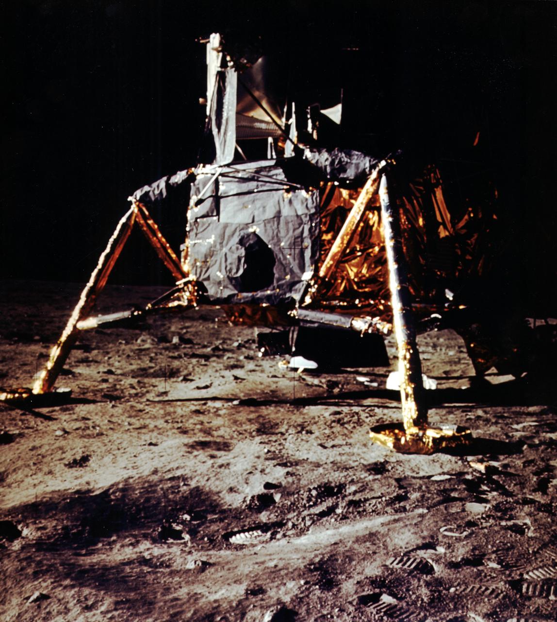
The first manned lunar landing mission, Apollo 11, launched from the Kennedy Space Center (KSC) in Florida via the Marshall Space Flight Center (MSFC) developed Saturn V launch vehicle on July 16, 1969 and safely returned to Earth on July 24, 1969. Aboard the space craft were astronauts Neil A. Armstrong, commander; Michael Collins, Command Module (CM) pilot; and Edwin E. (Buzz) Aldrin Jr., Lunar Module (LM) pilot. The CM, piloted by Michael Collins, remained in a parking orbit around the Moon while the LM, named “Eagle’’, carrying astronauts Armstrong and Aldrin, landed on the Moon in the Sea of Tranquility. The LM was a two part spacecraft. Its lower or descent stage had the landing gear, engines, and fuel needed for the landing. When the LM blasted off the Moon, the descent stage served as the launching pad for its companion ascent stage, which was also home for the two astronauts on the surface of the Moon. The LM was full of gear with which to communicate, navigate, and rendezvous. It also had its own propulsion system, and an engine to lift it off the Moon and send it on a course toward the orbiting CM. This photograph shows a close up of the LM on the Lunar surface.

AS12-46-6790 (19 Nov. 1969) --- Astronaut Alan L. Bean, lunar module pilot, is photographed at quadrant II of the Lunar Module (LM) during the first Apollo 12 extravehicular activity (EVA) on the moon. This picture was taken by astronaut Charles Conrad Jr., commander. Here, Bean is using a fuel transfer tool to remove the fuel element from the fuel cask mounted on the LM's descent stage. The fuel element was then placed in the Radioisotope Thermoelectric Generator (RTG), the power source for the Apollo Lunar Surface Experiments Package (ALSEP) which was deployed on the moon by the two astronauts. The RTG is next to Bean's right leg. While astronauts Conrad and Bean descended in the LM "Intrepid" to explore the Ocean of Storms region of the moon, astronaut Richard F. Gordon Jr., command module pilot, remained with the Command and Service Modules (CSM) "Yankee Clipper" in lunar orbit.
S72-35614 (23 April 1972) --- The Apollo 16 Lunar Module "Orion" ascent stage makes its liftoff from the lunar surface in this reproduction taken from a color television transmission made by the RCA color TV camera mounted on the Lunar Roving Vehicle (LRV). Remotely controlled from NASA's Mission Control Center (MCC) in Houston, the LRV-mounted camera made it possible for persons on Earth to watch the LM's launch from the moon. Liftoff occurred at 175:44 ground elapsed time, 7:26 p.m. (CST), April 23, 1972. The "Orion" ascent stage, with astronauts John W. Young and Charles M. Duke Jr. aboard, returned from the lunar surface to rejoin the Command and Service Modules (CSM) orbiting the moon. Astronaut Thomas K. (Ken) Mattingly II remained with the CSM in lunar orbit while Young and Duke descended in the LM to explore the Descartes landing site. The LM descent stage is used as a launching platform and remains behind on the moon.
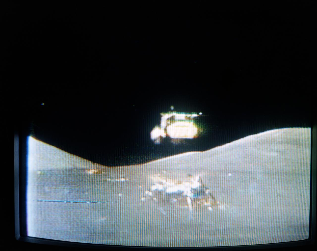
S72-55421 (14 Dec. 1972) --- The Apollo 17 Lunar Module (LM) "Challenger" ascent stage leaves the Taurus-Littrow landing site as it makes its spectacular liftoff from the lunar surface, as seen in this reproduction taken from a color television transmission made by the color RCA TV camera mounted on the Lunar Roving Vehicle (LRV). The LRV-mounted TV camera, remotely controlled from the Mission Control Center (MCC) in Houston, made it possible for people on Earth to watch the fantastic event. The LM liftoff was at 188:01:36 ground elapsed time, 4:54:36 p.m. (CST), Thursday, Dec. 14, 1972. The LM ascent stage, with astronauts Eugene A. Cernan and Harrison H. Schmitt aboard, returned from the lunar surface to rejoin the Command and Service Modules (CSM) orbiting the moon. Astronaut Ronald E. Evans remained with the CSM in lunar orbit while Cernan and Schmitt explored the moon. The LM descent stage is used as a launching platform and remains behind on the moon. Here, the two stages have completely separated and the ascent stage is headed skyward.
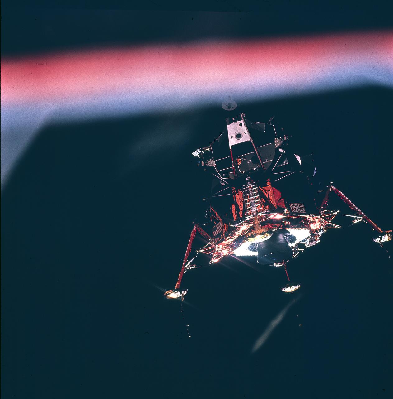
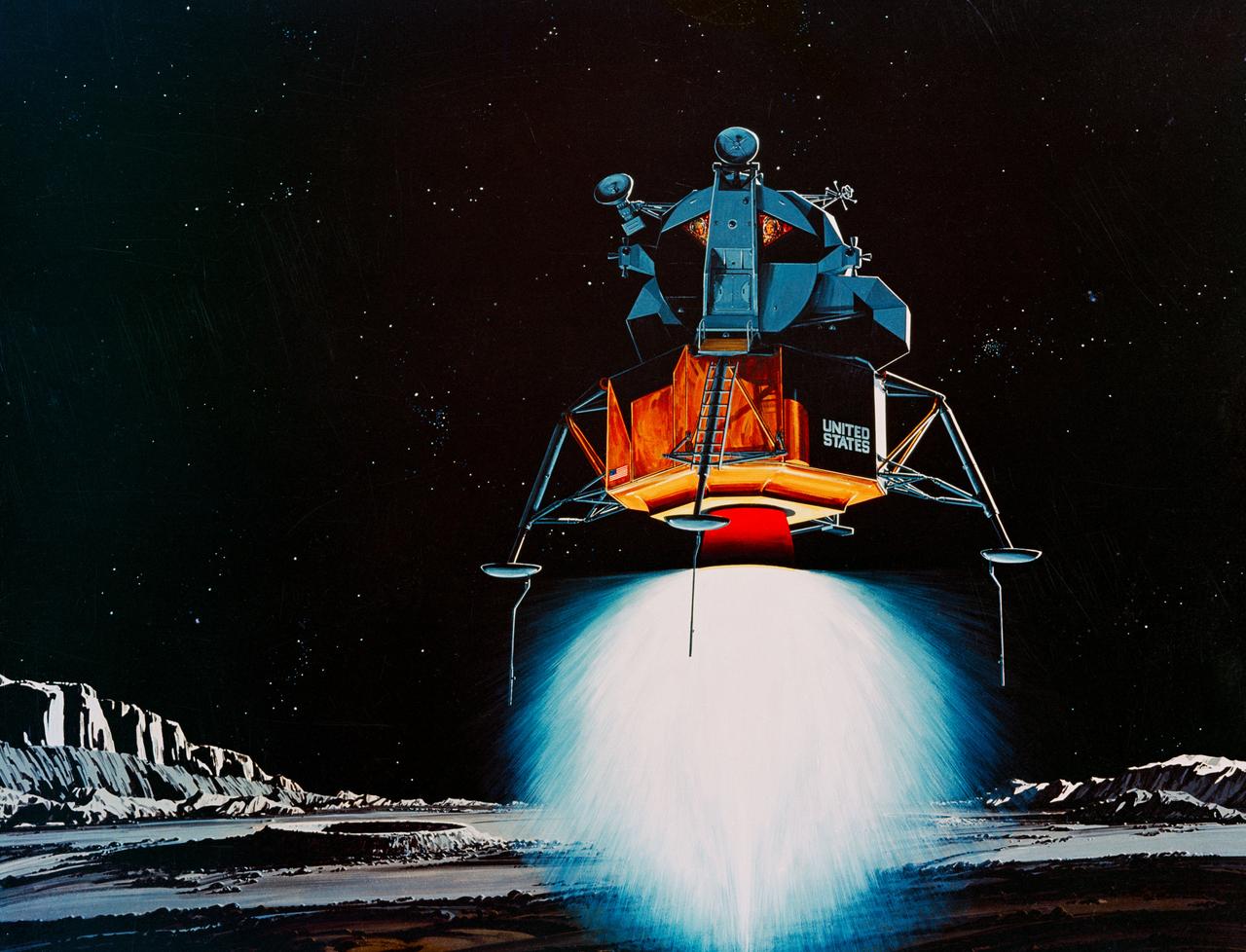
Carrying astronauts Neil A. Armstrong and Edwin E. Aldrin, Jr., the Lunar Module (LM) “Eagle” was the first crewed vehicle to land on the Moon. The LM landed on the moon’s surface on July 20, 1969 in the region known as Mare Tranquilitatis (the Sea of Tranquility). The LM is shown here making its descent to the lunar surface, while Astronaut Collins piloted the Command Module in a parking orbit around the Moon. The Apollo 11 mission launched from The Kennedy Space Center, Florida aboard a Saturn V launch vehicle on July 16, 1969 and safely returned to Earth on July 24, 1969. The 3-man crew aboard the flight consisted of Neil A. Armstrong, commander; Michael Collins, Command Module pilot; and Edwin E. Aldrin Jr., Lunar Module pilot. Armstrong was the first human to ever stand on the lunar surface. As he stepped off the LM, Armstrong proclaimed, “That’s one small step for man, one giant leap for mankind”. He was followed by Edwin (Buzz) Aldrin, describing the lunar surface as Magnificent desolation. The crew collected 47 pounds of lunar surface material which was returned to Earth for analysis. The surface exploration was concluded in 2½ hours. With the success of Apollo 11, the national objective to land men on the Moon and return them safely to Earth had been accomplished. The Saturn V vehicle was developed by the Marshall Space Flight Center (MSFC) under the direction of Dr. von Braun.
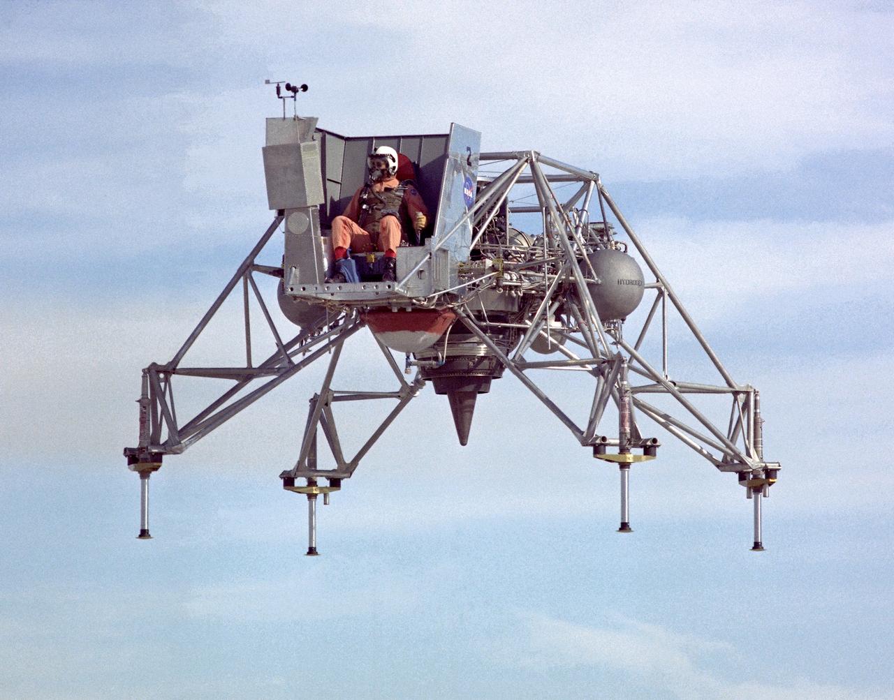
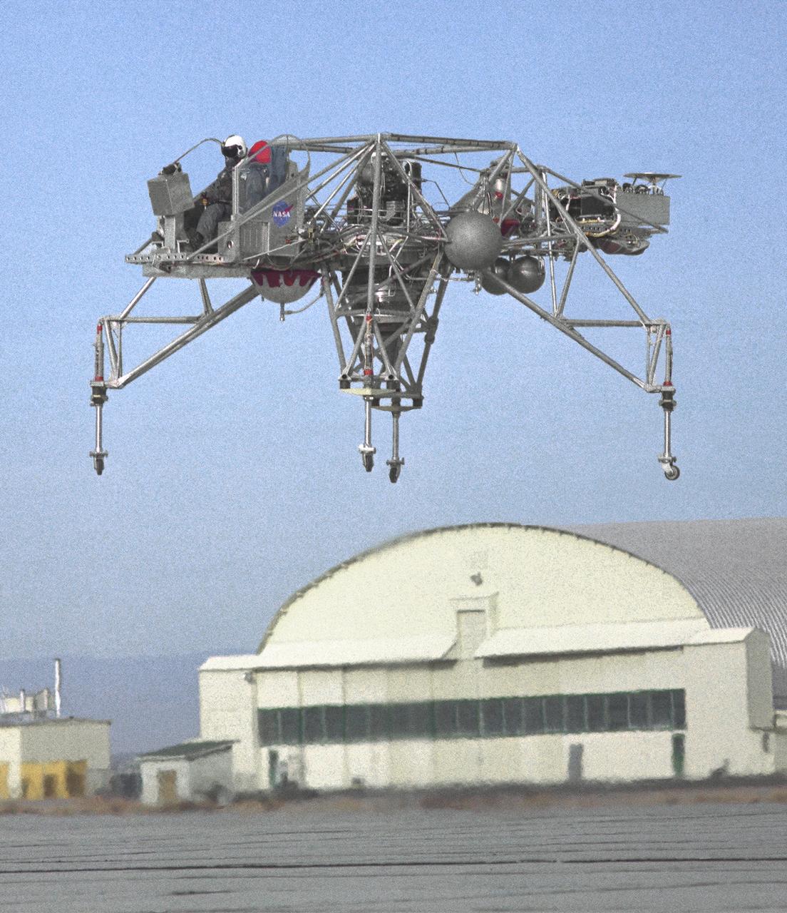
In this 1967 NASA Flight Reserch Center photograph the Lunar Landing Research Vehicle (LLRV) is viewed from the front. This photograph provideds a good view of the pilot’s platform with the restrictive cockpit view like that of he real Lunar Module (LM) When Apollo planning was underway in 1960, NASA was looking for a simulator to profile the descent to the Moon's surface. Three concepts surfaced: an electronic simulator, a tethered device, and the ambitious Dryden contribution, a free-flying vehicle. All three became serious projects, but eventually the NASA Flight Research Center’s (FRC) Lunar Landing Research Vehicle (LLRV) became the most significant one. After conceptual planning and meetings with engineers from Bell Aerosystems Company, Buffalo, N.Y., NASA FRC issued a $3.6 million production contract awarded in 1963, for delivery of the first of two vehicles for flight studies. Built of tubular aluminum alloy like a giant four-legged bedstead, the vehicle was to simulate a lunar landing profile from around 1500 feet to the Moon’s surface. The LLRV had a turbofan engine mounted vertically in a gimbal, with 4200 pounds of thrust. The engine, lifted the vehicle up to the test altitude and was then throttled back to support five-sixths of the vehicle's weight, thus simulating the reduced gravity of the Moon. Two lift rockets with thrust that could be varied from 100 to 500 pounds handled the LLRV's rate of descent and horizontal translations. Sixteen smaller rockets, mounted in pairs, gave the pilot control in pitch, yaw, and roll.. The pilot’s platform extended forward between two legs while an electronics platform, similarly located, extended rearward. The pilot had a zero-zero ejection seat that would then lift him away to safety. The two LLRVs were shipped from Bell to the FRC in April 1964, with program emphasis on vehicle No. 1. The first flight, Oct. 30, 1964, NASA research pilot Joe Walker flew it three times for a total of just under 60 seconds
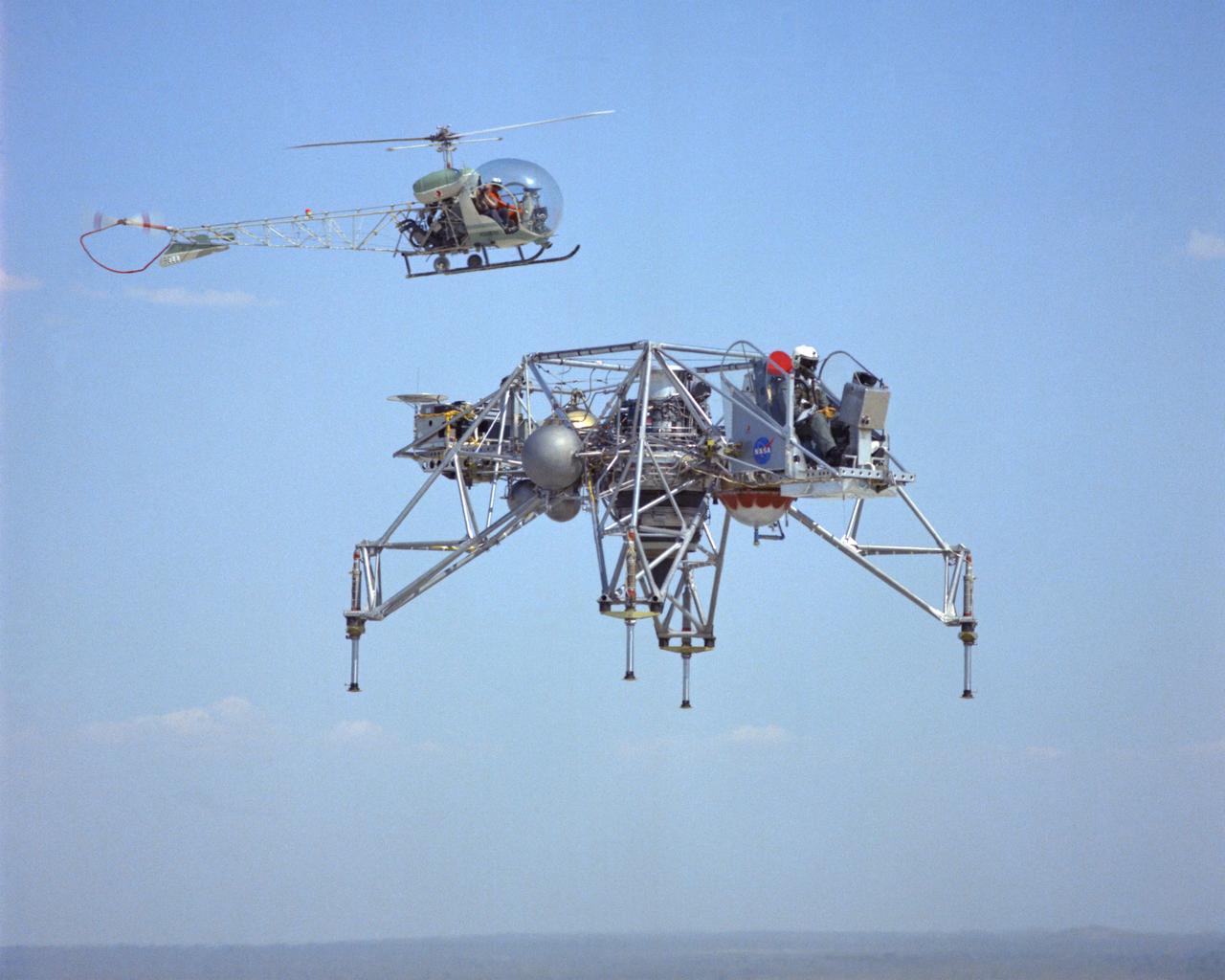
LLRV flight #1-16-61F with Bell 47 Helicopter providing chase support. The use of chase planes was a critical part of flight research well before the establishment of what was then called the NACA Muroc Flight Test Unit in September 1947 (now the NASA Dryden Flight Research Center). They act as a second set of eyes for the research pilot, warning him of any problems. When test flights of the LLRV began in October 1964, chase support for the vehicle was supplied by a Bell 47 helicopter. It could hover close by, providing information such as altitude and descent rate. LLRV test operations were phased out in late 1966 and early 1967. When Apollo planning was underway in 1960, NASA was looking for a simulator to profile the descent to the Moon's surface. Three concepts surfaced: an electronic simulator, a tethered device, and the ambitious Dryden contribution, a free-flying vehicle. All three became serious projects, but eventually the NASA Flight Research Center’s (FRC) Lunar Landing Research Vehicle (LLRV) became the most significant one. After conceptual planning and meetings with engineers from Bell Aerosystems Company, Buffalo, N.Y., NASA FRC issued a $3.6 million production contract awarded in 1963, for delivery of the first of two vehicles for flight studies. Built of tubular aluminum alloy like a giant four-legged bedstead, the vehicle was to simulate a lunar landing profile from around 1500 feet to the Moon’s surface. The LLRV had a turbofan engine mounted vertically in a gimbal, with 4200 pounds of thrust. The engine, lifted the vehicle up to the test altitude and was then throttled back to support five-sixths of the vehicle's weight, thus simulating the reduced gravity of the Moon. Two lift rockets with thrust that could be varied from 100 to 500 pounds handled the LLRV's rate of descent and horizontal translations. Sixteen smaller rockets, mounted in pairs, gave the pilot control in pitch, yaw, and roll. The pilot’s platform extended forward between t
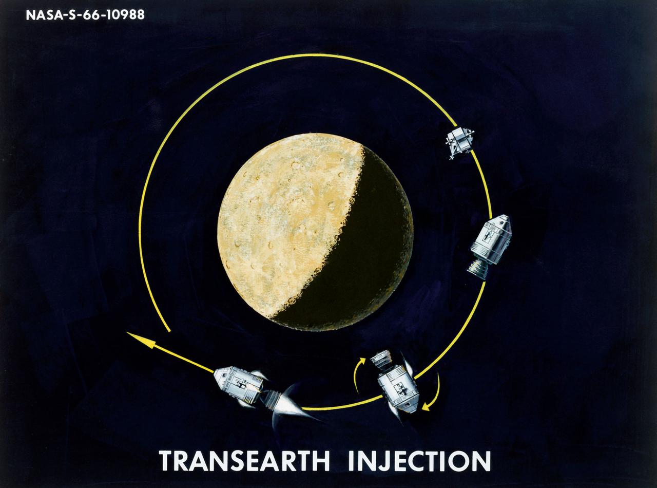
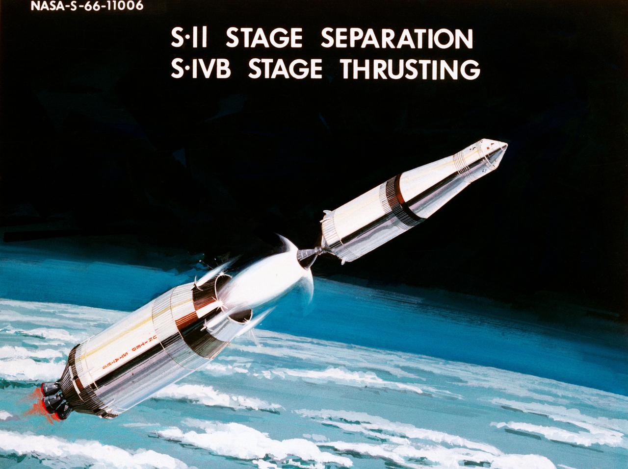
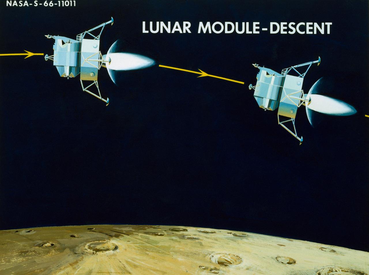
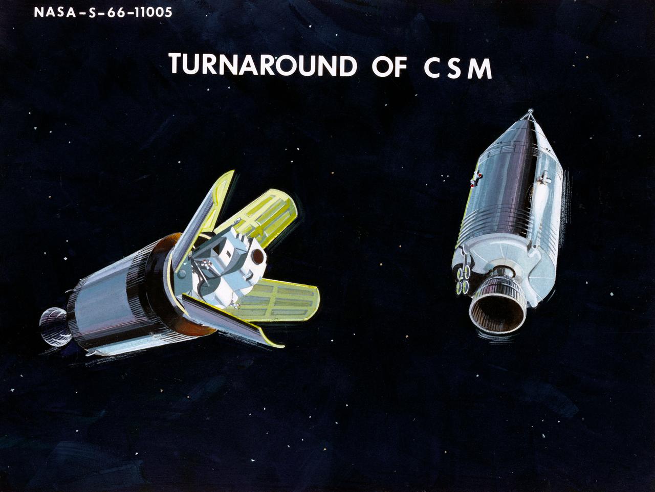
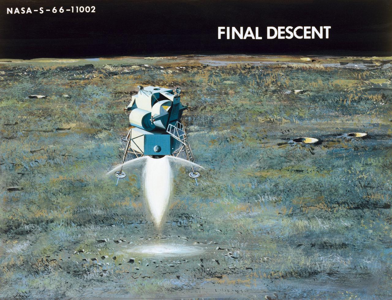
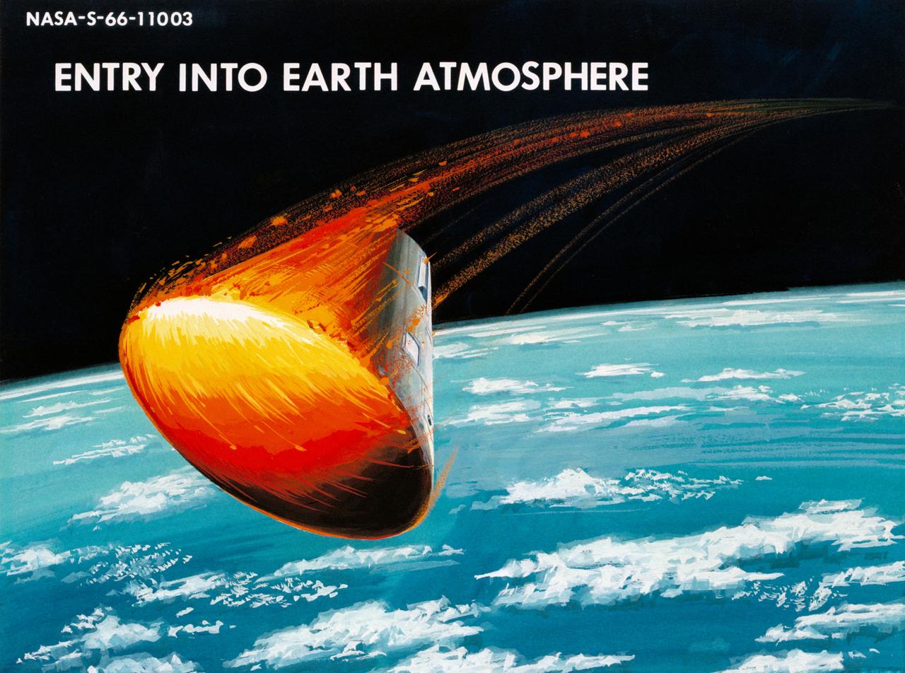
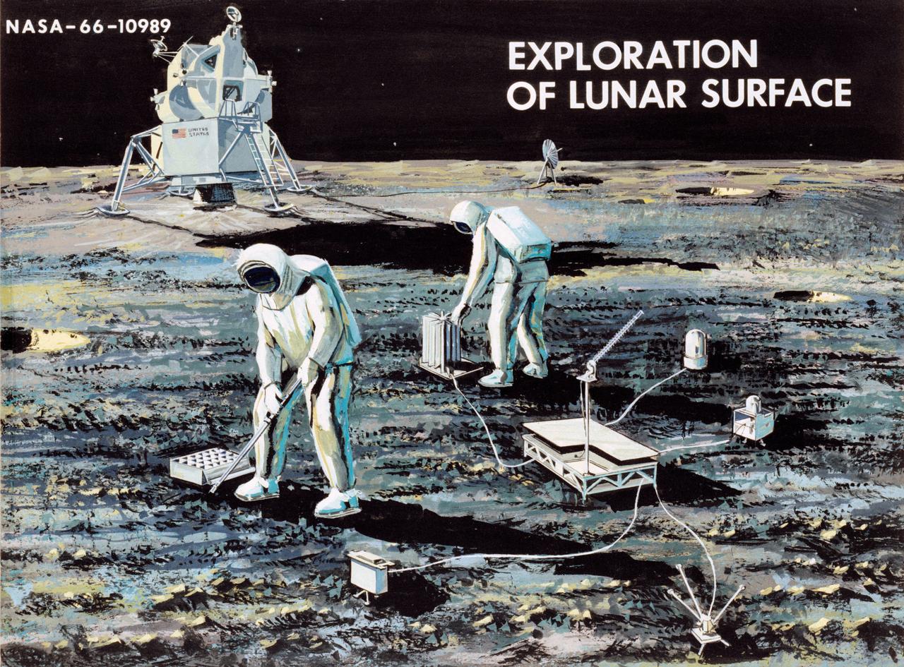
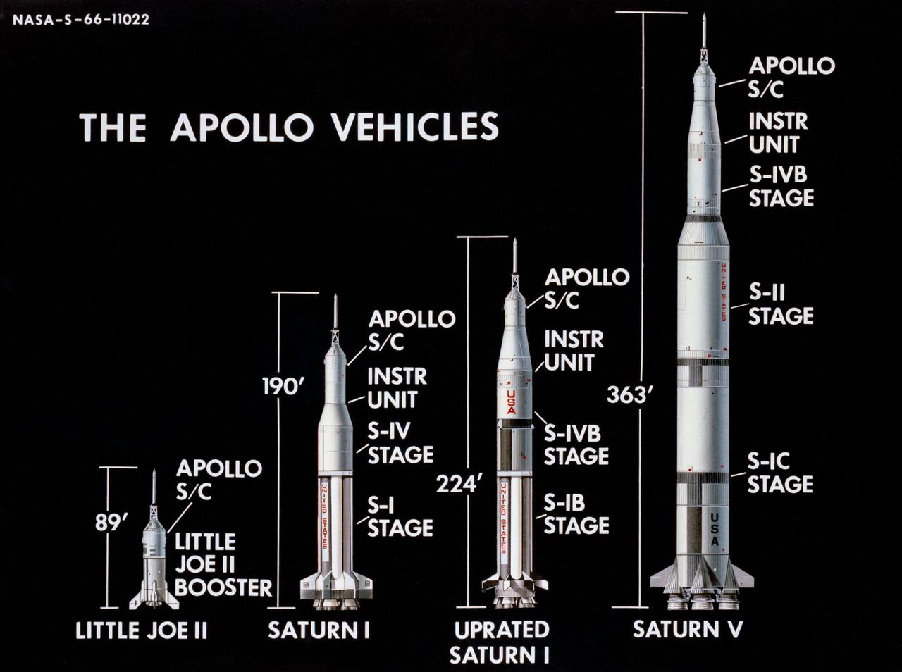
Artist Concepts, Apollo Mission: S66-10983: Ascent Stage Liftoff (S66-05094) S66-10984: Orientation During Ascent Phase (S66-05098) S66-10985: Midcourse Coast (S66-05113) S66-10986: Survey of Landing Site (S66-05117) S66-10987: Lunar Module (LM) Jettison (S66-05089) S66-10988: Trans-Earth Injection (S66-05090) S66-10989: Exploration on Lunar Surface Apollo Surface Lunar Exploration Experiment (ASLEP) S66-10990: Liftoff (S66-05125) S66-10991: Command Module (CM)-Service Module (SM) Separation (S66-05101 N/F) S66-10992: Touchdown on Lunar Surface (S66-05115) S66-10993: Transfer Orbit Insertion (S66-05111) S66-10994: Drogue Parachute Deployment S66-10995: S-IC Stage Separation S-II Stage Thrusting (S66-05099) S66-10996: Jettison Launch Escape System (S66-05114) S66-10997: Main Parachute Deployment (S66-05091) S66-10998: Mid-course correction (S66-05088) S66-10999: Lunar Orbit Insertion (S66-05086) S66-11000: Command Service Module (CSM)-LM Docked in LM Adapter-S-IVB (S66-06526) S66-11001: Docking and Separation of spacecraft from S-IVB (S66-05107) S66-11002: Final Descent (S66-05096) S66-11003: Entry into Earth Atmosphere (S66-05096) S66-11004: Deploy S/C LM Adapter-Separate CSM from LM-S-IVB (S66-06525 & 05105) S66-11005: Turnaround of CSM (S66-05104) S66-11006: S-II Stage Separation S-IVB Stage Thrusting (S66-05102) S66-11007: LM Ascent CSM Docked (S66-05100) S66-11008: Midcourse Correction SPS Mode (S66-05106) S66-11009: Earth Orbit Insertion of S-IVB & S/C (S66-05092) S66-11010: Trans-lunar Injection (S66-05116) S66-11011: LM Descent (S66-05110) S66-11012: S-IVB Stage Operations (S66-05112 N/F) S66-11013: Spacecraft Recovery (S66-05126) S66-11014: Lunar Orbit (S66-05103) S66-11015: CSM-LM Docking (S66-05095) S66-11016: Entry CM (S66-5109) S66-11017: Midcourse Corrections to Lunar Landing (S66-08486) S66-11018: Midcourse Corrections to Lunar Landing w/Overlay (S66-05083) S66-11019: Earth Launch Phase w/Overlay (S66-08485 & 05119) S66-11020: Earth Launch Phase (S66-08487 & S66-05084) S66-11022: Apollo Vehicles (S66-05127) S66-11024: Transfer to LM (S66-05082) S66-11025: Lunar Launch Phase S66-11027: Trans-earth Separation of C/M from S/M-C/M return to Earth (S66-05097) S66-11028: CSM-LM Separation, LM Descent to Moon (S66-05108) MSC, Houston, TX Also available in B&W 12/1965 - 06/1966

Artist Concepts, Apollo Mission: S66-10983: Ascent Stage Liftoff (S66-05094) S66-10984: Orientation During Ascent Phase (S66-05098) S66-10985: Midcourse Coast (S66-05113) S66-10986: Survey of Landing Site (S66-05117) S66-10987: Lunar Module (LM) Jettison (S66-05089) S66-10988: Trans-Earth Injection (S66-05090) S66-10989: Exploration on Lunar Surface Apollo Surface Lunar Exploration Experiment (ASLEP) S66-10990: Liftoff (S66-05125) S66-10991: Command Module (CM)-Service Module (SM) Separation (S66-05101 N/F) S66-10992: Touchdown on Lunar Surface (S66-05115) S66-10993: Transfer Orbit Insertion (S66-05111) S66-10994: Drogue Parachute Deployment S66-10995: S-IC Stage Separation S-II Stage Thrusting (S66-05099) S66-10996: Jettison Launch Escape System (S66-05114) S66-10997: Main Parachute Deployment (S66-05091) S66-10998: Mid-course correction (S66-05088) S66-10999: Lunar Orbit Insertion (S66-05086) S66-11000: Command Service Module (CSM)-LM Docked in LM Adapter-S-IVB (S66-06526) S66-11001: Docking and Separation of spacecraft from S-IVB (S66-05107) S66-11002: Final Descent (S66-05096) S66-11003: Entry into Earth Atmosphere (S66-05096) S66-11004: Deploy S/C LM Adapter-Separate CSM from LM-S-IVB (S66-06525 & 05105) S66-11005: Turnaround of CSM (S66-05104) S66-11006: S-II Stage Separation S-IVB Stage Thrusting (S66-05102) S66-11007: LM Ascent CSM Docked (S66-05100) S66-11008: Midcourse Correction SPS Mode (S66-05106) S66-11009: Earth Orbit Insertion of S-IVB & S/C (S66-05092) S66-11010: Trans-lunar Injection (S66-05116) S66-11011: LM Descent (S66-05110) S66-11012: S-IVB Stage Operations (S66-05112 N/F) S66-11013: Spacecraft Recovery (S66-05126) S66-11014: Lunar Orbit (S66-05103) S66-11015: CSM-LM Docking (S66-05095) S66-11016: Entry CM (S66-5109) S66-11017: Midcourse Corrections to Lunar Landing (S66-08486) S66-11018: Midcourse Corrections to Lunar Landing w/Overlay (S66-05083) S66-11019: Earth Launch Phase w/Overlay (S66-08485 & 05119) S66-11020: Earth Launch Phase (S66-08487 & S66-05084) S66-11022: Apollo Vehicles (S66-05127) S66-11024: Transfer to LM (S66-05082) S66-11025: Lunar Launch Phase S66-11027: Trans-earth Separation of C/M from S/M-C/M return to Earth (S66-05097) S66-11028: CSM-LM Separation, LM Descent to Moon (S66-05108) MSC, Houston, TX Also available in B&W 12/1965 - 06/1966
Artist Concepts, Apollo Mission: S66-10983: Ascent Stage Liftoff (S66-05094) S66-10984: Orientation During Ascent Phase (S66-05098) S66-10985: Midcourse Coast (S66-05113) S66-10986: Survey of Landing Site (S66-05117) S66-10987: Lunar Module (LM) Jettison (S66-05089) S66-10988: Trans-Earth Injection (S66-05090) S66-10989: Exploration on Lunar Surface Apollo Surface Lunar Exploration Experiment (ASLEP) S66-10990: Liftoff (S66-05125) S66-10991: Command Module (CM)-Service Module (SM) Separation (S66-05101 N/F) S66-10992: Touchdown on Lunar Surface (S66-05115) S66-10993: Transfer Orbit Insertion (S66-05111) S66-10994: Drogue Parachute Deployment S66-10995: S-IC Stage Separation S-II Stage Thrusting (S66-05099) S66-10996: Jettison Launch Escape System (S66-05114) S66-10997: Main Parachute Deployment (S66-05091) S66-10998: Mid-course correction (S66-05088) S66-10999: Lunar Orbit Insertion (S66-05086) S66-11000: Command Service Module (CSM)-LM Docked in LM Adapter-S-IVB (S66-06526) S66-11001: Docking and Separation of spacecraft from S-IVB (S66-05107) S66-11002: Final Descent (S66-05096) S66-11003: Entry into Earth Atmosphere (S66-05096) S66-11004: Deploy S/C LM Adapter-Separate CSM from LM-S-IVB (S66-06525 & 05105) S66-11005: Turnaround of CSM (S66-05104) S66-11006: S-II Stage Separation S-IVB Stage Thrusting (S66-05102) S66-11007: LM Ascent CSM Docked (S66-05100) S66-11008: Midcourse Correction SPS Mode (S66-05106) S66-11009: Earth Orbit Insertion of S-IVB & S/C (S66-05092) S66-11010: Trans-lunar Injection (S66-05116) S66-11011: LM Descent (S66-05110) S66-11012: S-IVB Stage Operations (S66-05112 N/F) S66-11013: Spacecraft Recovery (S66-05126) S66-11014: Lunar Orbit (S66-05103) S66-11015: CSM-LM Docking (S66-05095) S66-11016: Entry CM (S66-5109) S66-11017: Midcourse Corrections to Lunar Landing (S66-08486) S66-11018: Midcourse Corrections to Lunar Landing w/Overlay (S66-05083) S66-11019: Earth Launch Phase w/Overlay (S66-08485 & 05119) S66-11020: Earth Launch Phase (S66-08487 & S66-05084) S66-11022: Apollo Vehicles (S66-05127) S66-11024: Transfer to LM (S66-05082) S66-11025: Lunar Launch Phase S66-11027: Trans-earth Separation of C/M from S/M-C/M return to Earth (S66-05097) S66-11028: CSM-LM Separation, LM Descent to Moon (S66-05108) MSC, Houston, TX Also available in B&W 12/1965 - 06/1966

Artist Concepts, Apollo Mission: S66-10983: Ascent Stage Liftoff (S66-05094) S66-10984: Orientation During Ascent Phase (S66-05098) S66-10985: Midcourse Coast (S66-05113) S66-10986: Survey of Landing Site (S66-05117) S66-10987: Lunar Module (LM) Jettison (S66-05089) S66-10988: Trans-Earth Injection (S66-05090) S66-10989: Exploration on Lunar Surface Apollo Surface Lunar Exploration Experiment (ASLEP) S66-10990: Liftoff (S66-05125) S66-10991: Command Module (CM)-Service Module (SM) Separation (S66-05101 N/F) S66-10992: Touchdown on Lunar Surface (S66-05115) S66-10993: Transfer Orbit Insertion (S66-05111) S66-10994: Drogue Parachute Deployment S66-10995: S-IC Stage Separation S-II Stage Thrusting (S66-05099) S66-10996: Jettison Launch Escape System (S66-05114) S66-10997: Main Parachute Deployment (S66-05091) S66-10998: Mid-course correction (S66-05088) S66-10999: Lunar Orbit Insertion (S66-05086) S66-11000: Command Service Module (CSM)-LM Docked in LM Adapter-S-IVB (S66-06526) S66-11001: Docking and Separation of spacecraft from S-IVB (S66-05107) S66-11002: Final Descent (S66-05096) S66-11003: Entry into Earth Atmosphere (S66-05096) S66-11004: Deploy S/C LM Adapter-Separate CSM from LM-S-IVB (S66-06525 & 05105) S66-11005: Turnaround of CSM (S66-05104) S66-11006: S-II Stage Separation S-IVB Stage Thrusting (S66-05102) S66-11007: LM Ascent CSM Docked (S66-05100) S66-11008: Midcourse Correction SPS Mode (S66-05106) S66-11009: Earth Orbit Insertion of S-IVB & S/C (S66-05092) S66-11010: Trans-lunar Injection (S66-05116) S66-11011: LM Descent (S66-05110) S66-11012: S-IVB Stage Operations (S66-05112 N/F) S66-11013: Spacecraft Recovery (S66-05126) S66-11014: Lunar Orbit (S66-05103) S66-11015: CSM-LM Docking (S66-05095) S66-11016: Entry CM (S66-5109) S66-11017: Midcourse Corrections to Lunar Landing (S66-08486) S66-11018: Midcourse Corrections to Lunar Landing w/Overlay (S66-05083) S66-11019: Earth Launch Phase w/Overlay (S66-08485 & 05119) S66-11020: Earth Launch Phase (S66-08487 & S66-05084) S66-11022: Apollo Vehicles (S66-05127) S66-11024: Transfer to LM (S66-05082) S66-11025: Lunar Launch Phase S66-11027: Trans-earth Separation of C/M from S/M-C/M return to Earth (S66-05097) S66-11028: CSM-LM Separation, LM Descent to Moon (S66-05108) MSC, Houston, TX Also available in B&W 12/1965 - 06/1966
Artist Concepts, Apollo Mission: S66-10983: Ascent Stage Liftoff (S66-05094) S66-10984: Orientation During Ascent Phase (S66-05098) S66-10985: Midcourse Coast (S66-05113) S66-10986: Survey of Landing Site (S66-05117) S66-10987: Lunar Module (LM) Jettison (S66-05089) S66-10988: Trans-Earth Injection (S66-05090) S66-10989: Exploration on Lunar Surface Apollo Surface Lunar Exploration Experiment (ASLEP) S66-10990: Liftoff (S66-05125) S66-10991: Command Module (CM)-Service Module (SM) Separation (S66-05101 N/F) S66-10992: Touchdown on Lunar Surface (S66-05115) S66-10993: Transfer Orbit Insertion (S66-05111) S66-10994: Drogue Parachute Deployment S66-10995: S-IC Stage Separation S-II Stage Thrusting (S66-05099) S66-10996: Jettison Launch Escape System (S66-05114) S66-10997: Main Parachute Deployment (S66-05091) S66-10998: Mid-course correction (S66-05088) S66-10999: Lunar Orbit Insertion (S66-05086) S66-11000: Command Service Module (CSM)-LM Docked in LM Adapter-S-IVB (S66-06526) S66-11001: Docking and Separation of spacecraft from S-IVB (S66-05107) S66-11002: Final Descent (S66-05096) S66-11003: Entry into Earth Atmosphere (S66-05096) S66-11004: Deploy S/C LM Adapter-Separate CSM from LM-S-IVB (S66-06525 & 05105) S66-11005: Turnaround of CSM (S66-05104) S66-11006: S-II Stage Separation S-IVB Stage Thrusting (S66-05102) S66-11007: LM Ascent CSM Docked (S66-05100) S66-11008: Midcourse Correction SPS Mode (S66-05106) S66-11009: Earth Orbit Insertion of S-IVB & S/C (S66-05092) S66-11010: Trans-lunar Injection (S66-05116) S66-11011: LM Descent (S66-05110) S66-11012: S-IVB Stage Operations (S66-05112 N/F) S66-11013: Spacecraft Recovery (S66-05126) S66-11014: Lunar Orbit (S66-05103) S66-11015: CSM-LM Docking (S66-05095) S66-11016: Entry CM (S66-5109) S66-11017: Midcourse Corrections to Lunar Landing (S66-08486) S66-11018: Midcourse Corrections to Lunar Landing w/Overlay (S66-05083) S66-11019: Earth Launch Phase w/Overlay (S66-08485 & 05119) S66-11020: Earth Launch Phase (S66-08487 & S66-05084) S66-11022: Apollo Vehicles (S66-05127) S66-11024: Transfer to LM (S66-05082) S66-11025: Lunar Launch Phase S66-11027: Trans-earth Separation of C/M from S/M-C/M return to Earth (S66-05097) S66-11028: CSM-LM Separation, LM Descent to Moon (S66-05108) MSC, Houston, TX Also available in B&W 12/1965 - 06/1966
Artist Concepts, Apollo Mission: S66-10983: Ascent Stage Liftoff (S66-05094) S66-10984: Orientation During Ascent Phase (S66-05098) S66-10985: Midcourse Coast (S66-05113) S66-10986: Survey of Landing Site (S66-05117) S66-10987: Lunar Module (LM) Jettison (S66-05089) S66-10988: Trans-Earth Injection (S66-05090) S66-10989: Exploration on Lunar Surface Apollo Surface Lunar Exploration Experiment (ASLEP) S66-10990: Liftoff (S66-05125) S66-10991: Command Module (CM)-Service Module (SM) Separation (S66-05101 N/F) S66-10992: Touchdown on Lunar Surface (S66-05115) S66-10993: Transfer Orbit Insertion (S66-05111) S66-10994: Drogue Parachute Deployment S66-10995: S-IC Stage Separation S-II Stage Thrusting (S66-05099) S66-10996: Jettison Launch Escape System (S66-05114) S66-10997: Main Parachute Deployment (S66-05091) S66-10998: Mid-course correction (S66-05088) S66-10999: Lunar Orbit Insertion (S66-05086) S66-11000: Command Service Module (CSM)-LM Docked in LM Adapter-S-IVB (S66-06526) S66-11001: Docking and Separation of spacecraft from S-IVB (S66-05107) S66-11002: Final Descent (S66-05096) S66-11003: Entry into Earth Atmosphere (S66-05096) S66-11004: Deploy S/C LM Adapter-Separate CSM from LM-S-IVB (S66-06525 & 05105) S66-11005: Turnaround of CSM (S66-05104) S66-11006: S-II Stage Separation S-IVB Stage Thrusting (S66-05102) S66-11007: LM Ascent CSM Docked (S66-05100) S66-11008: Midcourse Correction SPS Mode (S66-05106) S66-11009: Earth Orbit Insertion of S-IVB & S/C (S66-05092) S66-11010: Trans-lunar Injection (S66-05116) S66-11011: LM Descent (S66-05110) S66-11012: S-IVB Stage Operations (S66-05112 N/F) S66-11013: Spacecraft Recovery (S66-05126) S66-11014: Lunar Orbit (S66-05103) S66-11015: CSM-LM Docking (S66-05095) S66-11016: Entry CM (S66-5109) S66-11017: Midcourse Corrections to Lunar Landing (S66-08486) S66-11018: Midcourse Corrections to Lunar Landing w/Overlay (S66-05083) S66-11019: Earth Launch Phase w/Overlay (S66-08485 & 05119) S66-11020: Earth Launch Phase (S66-08487 & S66-05084) S66-11022: Apollo Vehicles (S66-05127) S66-11024: Transfer to LM (S66-05082) S66-11025: Lunar Launch Phase S66-11027: Trans-earth Separation of C/M from S/M-C/M return to Earth (S66-05097) S66-11028: CSM-LM Separation, LM Descent to Moon (S66-05108) MSC, Houston, TX Also available in B&W 12/1965 - 06/1966
Artist Concepts, Apollo Mission: S66-10983: Ascent Stage Liftoff (S66-05094) S66-10984: Orientation During Ascent Phase (S66-05098) S66-10985: Midcourse Coast (S66-05113) S66-10986: Survey of Landing Site (S66-05117) S66-10987: Lunar Module (LM) Jettison (S66-05089) S66-10988: Trans-Earth Injection (S66-05090) S66-10989: Exploration on Lunar Surface Apollo Surface Lunar Exploration Experiment (ASLEP) S66-10990: Liftoff (S66-05125) S66-10991: Command Module (CM)-Service Module (SM) Separation (S66-05101 N/F) S66-10992: Touchdown on Lunar Surface (S66-05115) S66-10993: Transfer Orbit Insertion (S66-05111) S66-10994: Drogue Parachute Deployment S66-10995: S-IC Stage Separation S-II Stage Thrusting (S66-05099) S66-10996: Jettison Launch Escape System (S66-05114) S66-10997: Main Parachute Deployment (S66-05091) S66-10998: Mid-course correction (S66-05088) S66-10999: Lunar Orbit Insertion (S66-05086) S66-11000: Command Service Module (CSM)-LM Docked in LM Adapter-S-IVB (S66-06526) S66-11001: Docking and Separation of spacecraft from S-IVB (S66-05107) S66-11002: Final Descent (S66-05096) S66-11003: Entry into Earth Atmosphere (S66-05096) S66-11004: Deploy S/C LM Adapter-Separate CSM from LM-S-IVB (S66-06525 & 05105) S66-11005: Turnaround of CSM (S66-05104) S66-11006: S-II Stage Separation S-IVB Stage Thrusting (S66-05102) S66-11007: LM Ascent CSM Docked (S66-05100) S66-11008: Midcourse Correction SPS Mode (S66-05106) S66-11009: Earth Orbit Insertion of S-IVB & S/C (S66-05092) S66-11010: Trans-lunar Injection (S66-05116) S66-11011: LM Descent (S66-05110) S66-11012: S-IVB Stage Operations (S66-05112 N/F) S66-11013: Spacecraft Recovery (S66-05126) S66-11014: Lunar Orbit (S66-05103) S66-11015: CSM-LM Docking (S66-05095) S66-11016: Entry CM (S66-5109) S66-11017: Midcourse Corrections to Lunar Landing (S66-08486) S66-11018: Midcourse Corrections to Lunar Landing w/Overlay (S66-05083) S66-11019: Earth Launch Phase w/Overlay (S66-08485 & 05119) S66-11020: Earth Launch Phase (S66-08487 & S66-05084) S66-11022: Apollo Vehicles (S66-05127) S66-11024: Transfer to LM (S66-05082) S66-11025: Lunar Launch Phase S66-11027: Trans-earth Separation of C/M from S/M-C/M return to Earth (S66-05097) S66-11028: CSM-LM Separation, LM Descent to Moon (S66-05108) MSC, Houston, TX Also available in B&W 12/1965 - 06/1966
Artist Concepts, Apollo Mission: S66-10983: Ascent Stage Liftoff (S66-05094) S66-10984: Orientation During Ascent Phase (S66-05098) S66-10985: Midcourse Coast (S66-05113) S66-10986: Survey of Landing Site (S66-05117) S66-10987: Lunar Module (LM) Jettison (S66-05089) S66-10988: Trans-Earth Injection (S66-05090) S66-10989: Exploration on Lunar Surface Apollo Surface Lunar Exploration Experiment (ASLEP) S66-10990: Liftoff (S66-05125) S66-10991: Command Module (CM)-Service Module (SM) Separation (S66-05101 N/F) S66-10992: Touchdown on Lunar Surface (S66-05115) S66-10993: Transfer Orbit Insertion (S66-05111) S66-10994: Drogue Parachute Deployment S66-10995: S-IC Stage Separation S-II Stage Thrusting (S66-05099) S66-10996: Jettison Launch Escape System (S66-05114) S66-10997: Main Parachute Deployment (S66-05091) S66-10998: Mid-course correction (S66-05088) S66-10999: Lunar Orbit Insertion (S66-05086) S66-11000: Command Service Module (CSM)-LM Docked in LM Adapter-S-IVB (S66-06526) S66-11001: Docking and Separation of spacecraft from S-IVB (S66-05107) S66-11002: Final Descent (S66-05096) S66-11003: Entry into Earth Atmosphere (S66-05096) S66-11004: Deploy S/C LM Adapter-Separate CSM from LM-S-IVB (S66-06525 & 05105) S66-11005: Turnaround of CSM (S66-05104) S66-11006: S-II Stage Separation S-IVB Stage Thrusting (S66-05102) S66-11007: LM Ascent CSM Docked (S66-05100) S66-11008: Midcourse Correction SPS Mode (S66-05106) S66-11009: Earth Orbit Insertion of S-IVB & S/C (S66-05092) S66-11010: Trans-lunar Injection (S66-05116) S66-11011: LM Descent (S66-05110) S66-11012: S-IVB Stage Operations (S66-05112 N/F) S66-11013: Spacecraft Recovery (S66-05126) S66-11014: Lunar Orbit (S66-05103) S66-11015: CSM-LM Docking (S66-05095) S66-11016: Entry CM (S66-5109) S66-11017: Midcourse Corrections to Lunar Landing (S66-08486) S66-11018: Midcourse Corrections to Lunar Landing w/Overlay (S66-05083) S66-11019: Earth Launch Phase w/Overlay (S66-08485 & 05119) S66-11020: Earth Launch Phase (S66-08487 & S66-05084) S66-11022: Apollo Vehicles (S66-05127) S66-11024: Transfer to LM (S66-05082) S66-11025: Lunar Launch Phase S66-11027: Trans-earth Separation of C/M from S/M-C/M return to Earth (S66-05097) S66-11028: CSM-LM Separation, LM Descent to Moon (S66-05108) MSC, Houston, TX Also available in B&W 12/1965 - 06/1966
Artist Concepts, Apollo Mission: S66-10983: Ascent Stage Liftoff (S66-05094) S66-10984: Orientation During Ascent Phase (S66-05098) S66-10985: Midcourse Coast (S66-05113) S66-10986: Survey of Landing Site (S66-05117) S66-10987: Lunar Module (LM) Jettison (S66-05089) S66-10988: Trans-Earth Injection (S66-05090) S66-10989: Exploration on Lunar Surface Apollo Surface Lunar Exploration Experiment (ASLEP) S66-10990: Liftoff (S66-05125) S66-10991: Command Module (CM)-Service Module (SM) Separation (S66-05101 N/F) S66-10992: Touchdown on Lunar Surface (S66-05115) S66-10993: Transfer Orbit Insertion (S66-05111) S66-10994: Drogue Parachute Deployment S66-10995: S-IC Stage Separation S-II Stage Thrusting (S66-05099) S66-10996: Jettison Launch Escape System (S66-05114) S66-10997: Main Parachute Deployment (S66-05091) S66-10998: Mid-course correction (S66-05088) S66-10999: Lunar Orbit Insertion (S66-05086) S66-11000: Command Service Module (CSM)-LM Docked in LM Adapter-S-IVB (S66-06526) S66-11001: Docking and Separation of spacecraft from S-IVB (S66-05107) S66-11002: Final Descent (S66-05096) S66-11003: Entry into Earth Atmosphere (S66-05096) S66-11004: Deploy S/C LM Adapter-Separate CSM from LM-S-IVB (S66-06525 & 05105) S66-11005: Turnaround of CSM (S66-05104) S66-11006: S-II Stage Separation S-IVB Stage Thrusting (S66-05102) S66-11007: LM Ascent CSM Docked (S66-05100) S66-11008: Midcourse Correction SPS Mode (S66-05106) S66-11009: Earth Orbit Insertion of S-IVB & S/C (S66-05092) S66-11010: Trans-lunar Injection (S66-05116) S66-11011: LM Descent (S66-05110) S66-11012: S-IVB Stage Operations (S66-05112 N/F) S66-11013: Spacecraft Recovery (S66-05126) S66-11014: Lunar Orbit (S66-05103) S66-11015: CSM-LM Docking (S66-05095) S66-11016: Entry CM (S66-5109) S66-11017: Midcourse Corrections to Lunar Landing (S66-08486) S66-11018: Midcourse Corrections to Lunar Landing w/Overlay (S66-05083) S66-11019: Earth Launch Phase w/Overlay (S66-08485 & 05119) S66-11020: Earth Launch Phase (S66-08487 & S66-05084) S66-11022: Apollo Vehicles (S66-05127) S66-11024: Transfer to LM (S66-05082) S66-11025: Lunar Launch Phase S66-11027: Trans-earth Separation of C/M from S/M-C/M return to Earth (S66-05097) S66-11028: CSM-LM Separation, LM Descent to Moon (S66-05108) MSC, Houston, TX Also available in B&W 12/1965 - 06/1966
Artist Concepts, Apollo Mission: S66-10983: Ascent Stage Liftoff (S66-05094) S66-10984: Orientation During Ascent Phase (S66-05098) S66-10985: Midcourse Coast (S66-05113) S66-10986: Survey of Landing Site (S66-05117) S66-10987: Lunar Module (LM) Jettison (S66-05089) S66-10988: Trans-Earth Injection (S66-05090) S66-10989: Exploration on Lunar Surface Apollo Surface Lunar Exploration Experiment (ASLEP) S66-10990: Liftoff (S66-05125) S66-10991: Command Module (CM)-Service Module (SM) Separation (S66-05101 N/F) S66-10992: Touchdown on Lunar Surface (S66-05115) S66-10993: Transfer Orbit Insertion (S66-05111) S66-10994: Drogue Parachute Deployment S66-10995: S-IC Stage Separation S-II Stage Thrusting (S66-05099) S66-10996: Jettison Launch Escape System (S66-05114) S66-10997: Main Parachute Deployment (S66-05091) S66-10998: Mid-course correction (S66-05088) S66-10999: Lunar Orbit Insertion (S66-05086) S66-11000: Command Service Module (CSM)-LM Docked in LM Adapter-S-IVB (S66-06526) S66-11001: Docking and Separation of spacecraft from S-IVB (S66-05107) S66-11002: Final Descent (S66-05096) S66-11003: Entry into Earth Atmosphere (S66-05096) S66-11004: Deploy S/C LM Adapter-Separate CSM from LM-S-IVB (S66-06525 & 05105) S66-11005: Turnaround of CSM (S66-05104) S66-11006: S-II Stage Separation S-IVB Stage Thrusting (S66-05102) S66-11007: LM Ascent CSM Docked (S66-05100) S66-11008: Midcourse Correction SPS Mode (S66-05106) S66-11009: Earth Orbit Insertion of S-IVB & S/C (S66-05092) S66-11010: Trans-lunar Injection (S66-05116) S66-11011: LM Descent (S66-05110) S66-11012: S-IVB Stage Operations (S66-05112 N/F) S66-11013: Spacecraft Recovery (S66-05126) S66-11014: Lunar Orbit (S66-05103) S66-11015: CSM-LM Docking (S66-05095) S66-11016: Entry CM (S66-5109) S66-11017: Midcourse Corrections to Lunar Landing (S66-08486) S66-11018: Midcourse Corrections to Lunar Landing w/Overlay (S66-05083) S66-11019: Earth Launch Phase w/Overlay (S66-08485 & 05119) S66-11020: Earth Launch Phase (S66-08487 & S66-05084) S66-11022: Apollo Vehicles (S66-05127) S66-11024: Transfer to LM (S66-05082) S66-11025: Lunar Launch Phase S66-11027: Trans-earth Separation of C/M from S/M-C/M return to Earth (S66-05097) S66-11028: CSM-LM Separation, LM Descent to Moon (S66-05108) MSC, Houston, TX Also available in B&W 12/1965 - 06/1966
Artist Concepts, Apollo Mission: S66-10983: Ascent Stage Liftoff (S66-05094) S66-10984: Orientation During Ascent Phase (S66-05098) S66-10985: Midcourse Coast (S66-05113) S66-10986: Survey of Landing Site (S66-05117) S66-10987: Lunar Module (LM) Jettison (S66-05089) S66-10988: Trans-Earth Injection (S66-05090) S66-10989: Exploration on Lunar Surface Apollo Surface Lunar Exploration Experiment (ASLEP) S66-10990: Liftoff (S66-05125) S66-10991: Command Module (CM)-Service Module (SM) Separation (S66-05101 N/F) S66-10992: Touchdown on Lunar Surface (S66-05115) S66-10993: Transfer Orbit Insertion (S66-05111) S66-10994: Drogue Parachute Deployment S66-10995: S-IC Stage Separation S-II Stage Thrusting (S66-05099) S66-10996: Jettison Launch Escape System (S66-05114) S66-10997: Main Parachute Deployment (S66-05091) S66-10998: Mid-course correction (S66-05088) S66-10999: Lunar Orbit Insertion (S66-05086) S66-11000: Command Service Module (CSM)-LM Docked in LM Adapter-S-IVB (S66-06526) S66-11001: Docking and Separation of spacecraft from S-IVB (S66-05107) S66-11002: Final Descent (S66-05096) S66-11003: Entry into Earth Atmosphere (S66-05096) S66-11004: Deploy S/C LM Adapter-Separate CSM from LM-S-IVB (S66-06525 & 05105) S66-11005: Turnaround of CSM (S66-05104) S66-11006: S-II Stage Separation S-IVB Stage Thrusting (S66-05102) S66-11007: LM Ascent CSM Docked (S66-05100) S66-11008: Midcourse Correction SPS Mode (S66-05106) S66-11009: Earth Orbit Insertion of S-IVB & S/C (S66-05092) S66-11010: Trans-lunar Injection (S66-05116) S66-11011: LM Descent (S66-05110) S66-11012: S-IVB Stage Operations (S66-05112 N/F) S66-11013: Spacecraft Recovery (S66-05126) S66-11014: Lunar Orbit (S66-05103) S66-11015: CSM-LM Docking (S66-05095) S66-11016: Entry CM (S66-5109) S66-11017: Midcourse Corrections to Lunar Landing (S66-08486) S66-11018: Midcourse Corrections to Lunar Landing w/Overlay (S66-05083) S66-11019: Earth Launch Phase w/Overlay (S66-08485 & 05119) S66-11020: Earth Launch Phase (S66-08487 & S66-05084) S66-11022: Apollo Vehicles (S66-05127) S66-11024: Transfer to LM (S66-05082) S66-11025: Lunar Launch Phase S66-11027: Trans-earth Separation of C/M from S/M-C/M return to Earth (S66-05097) S66-11028: CSM-LM Separation, LM Descent to Moon (S66-05108) MSC, Houston, TX Also available in B&W 12/1965 - 06/1966
S71-41511 (2 Aug. 1971) --- The Apollo 15 Lunar Module (LM) "Falcon" is seen only seconds before ascent stage liftoff in this color reproduction taken from a transmission made by the RCA color television camera mounted on the Lunar Roving Vehicle (LRV). The LRV was parked about 300 feet east of the LM. The LRV-mounted TV camera, remotely controlled from the Mission Control Center (MCC), made it possible for people on Earth to watch the LM's launch from the moon. The LM liftoff was at 171:37 ground elapsed time. The "Falcon" ascent stage, with astronauts David R. Scott, commander; and James B. Irwin, lunar module pilot, aboard, returned from the lunar surface to rejoin the Command and Service Modules (CSM) orbiting the moon. Astronaut Alfred M. Worden, command module pilot, remained with the CSM in lunar orbit while Scott and Irwin explored the moon. The LM descent stage is used as a launching platform and remains behind on the moon. This is part one of a four-part sequence.
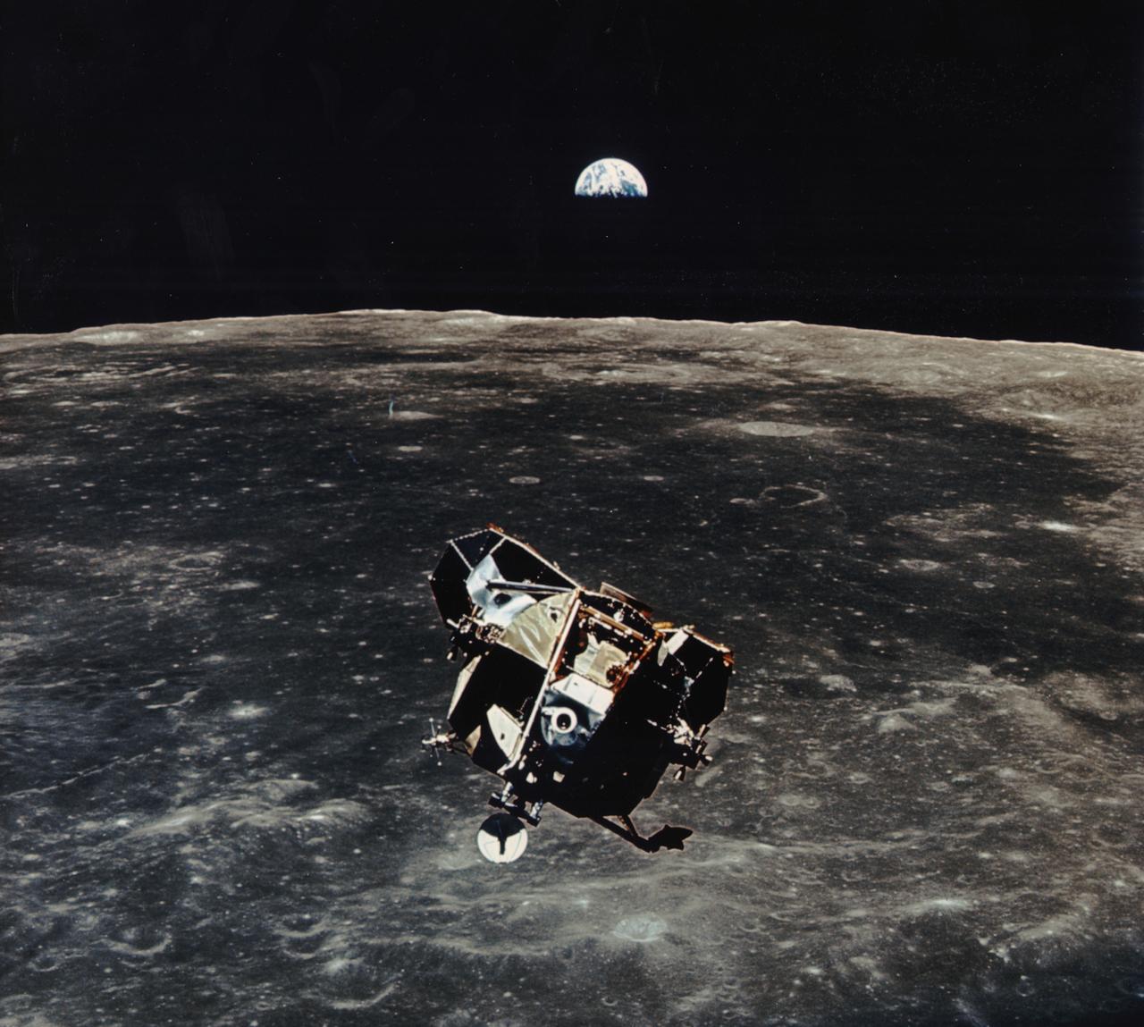
The Apollo 11 mission launched from the Kennedy Space Center (KSC) in Florida via the Marshall Space Flight Center (MSFC) developed Saturn V launch vehicle on July 16, 1969 and safely returned to Earth on July 24, 1969. Aboard the space craft were astronauts Neil A. Armstrong, commander; Michael Collins, Command Module (CM) pilot; and Edwin E. (Buzz) Aldrin Jr., Lunar Module (LM) pilot. With the success of Apollo 11, the national objective to land men on the Moon and return them safely to Earth had been accomplished. After 2½ hours of surface exploration, astronauts Neil Armstrong and Edwin Aldrin returned to the LM “Eagle” for rest, eating, and checkout of the vehicle in preparation for liftoff. The LM was a two part spacecraft. Its lower or descent stage had the landing gear, engines, and fuel needed for the landing. When the LM blasted off the Moon, the descent stage served as the launching pad for its companion ascent stage, which was also home for the two astronauts on the surface of the Moon. The LM was full of gear with which to communicate, navigate, and rendezvous. It also had its own propulsion system, and an engine to lift it off the Moon and send it on a course toward the orbiting CM. In this photograph, the ascent stage is seen back dropped by Earth just prior to its rendezvous with the CM.
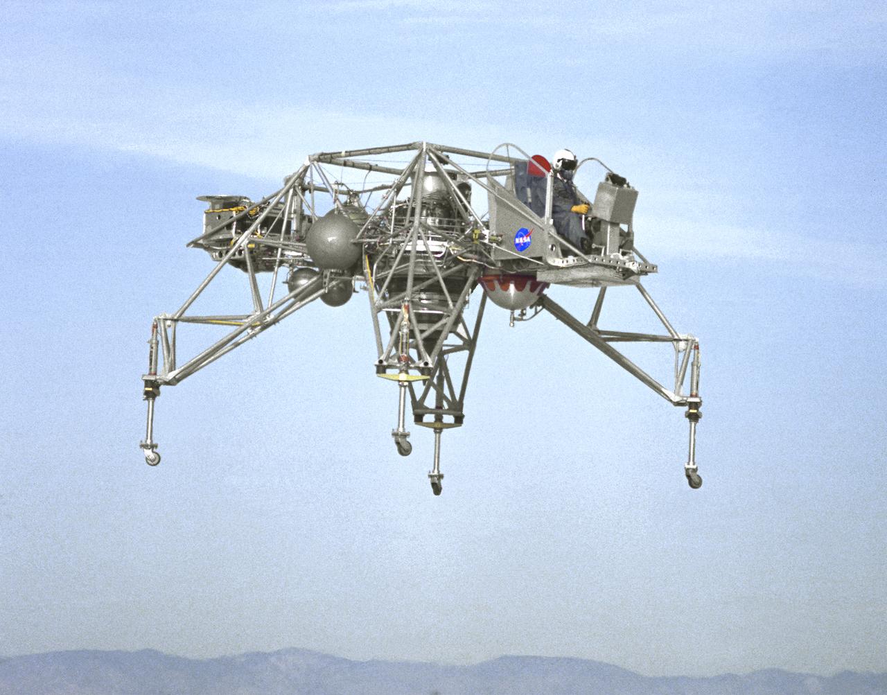
In this NASA Flight Reserch Center photograph the Lunar Landing Research Vehicle (LLRV) number 1 is shown in flight. When Apollo planning was underway in 1960, NASA was looking for a simulator to profile the descent to the Moon's surface. Three concepts surfaced: an electronic simulator, a tethered device, and the ambitious Dryden contribution, a free-flying vehicle. All three became serious projects, but eventually the NASA Flight Research Center's (FRC) Landing Research Vehicle (LLRV) became the most significant one. Hubert M. Drake is credited with originating the idea, while Donald Bellman and Gene Matranga were senior engineers on the project, with Bellman, the project manager. Simultaneously, and independently, Bell Aerosystems Company, Buffalo, N.Y., a company with experience in vertical takeoff and landing (VTOL) aircraft, had conceived a similar free-flying simulator and proposed their concept to NASA headquarters. NASA Headquarters put FRC and Bell together to collaborate. The challenge was; to allow a pilot to make a vertical landing on Earth in a simulated Moon environment, one sixth of the Earth's gravity and with totally transparent aerodynamic forces in a "free flight" vehicle with no tether forces acting on it. Built of tubular aluminum like a giant four-legged bedstead, the vehicle was to simulate a lunar landing profile from around 1500 feet to the Moon's surface. To do this, the LLRV had a General Electric CF-700-2V turbofan engine mounted vertically in gimbals, with 4200 pounds of thrust. The engine, using JP-4 fuel, got the vehicle up to the test altitude and was then throttled back to support five-sixths of the vehicle's weight, simulating the reduced gravity of the Moon. Two hydrogen-peroxide lift rockets with thrust that could be varied from 100 to 500 pounds handled the LLRV's rate of descent and horizontal translations. Sixteen smaller hydrogen-peroxide rockets, mounted in pairs, gave the pilot control in pitch, yaw, and roll. On the LLRV,
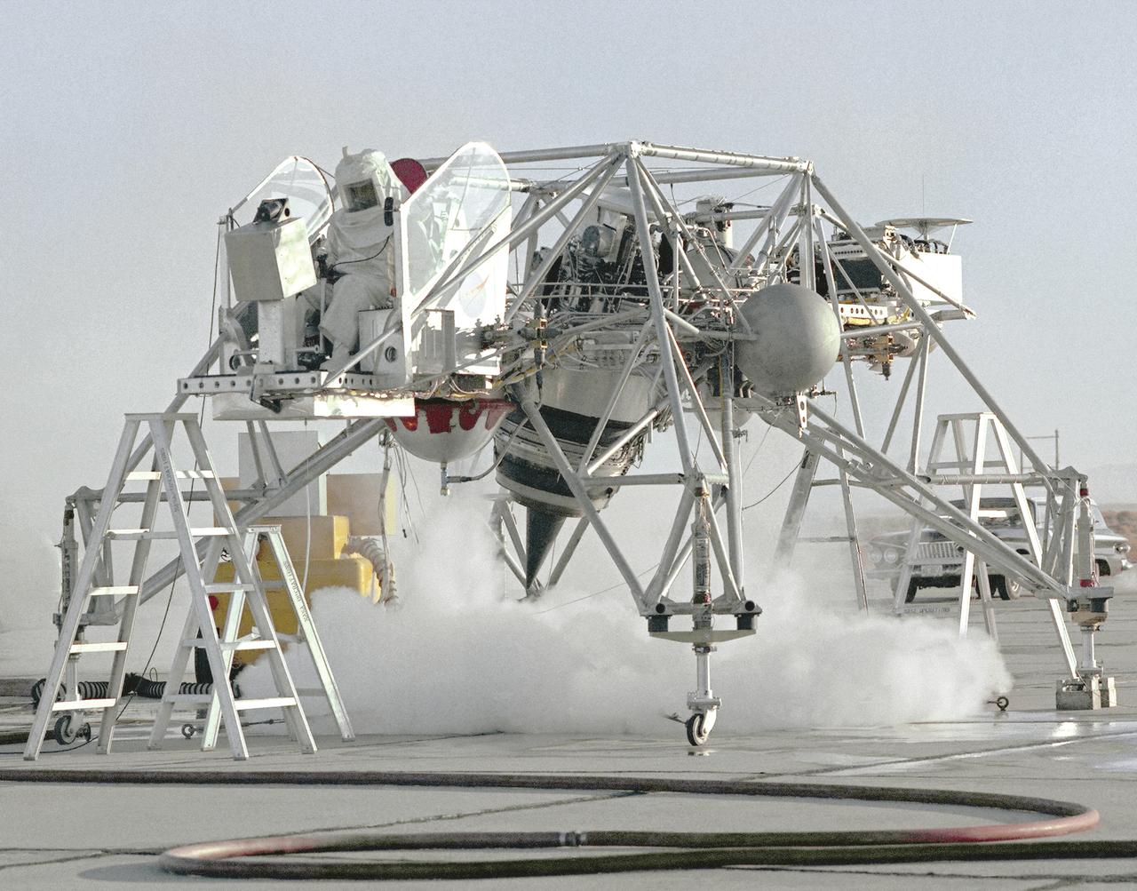
This 1964 NASA Flight Reserch Center photograph shows a ground engine test underway on the Lunar Landing Research Vehicle (LLRV) number 1. When Apollo planning was underway in 1960, NASA was looking for a simulator to profile the descent to the Moon's surface. Three concepts surfaced: an electronic simulator, a tethered device, and the ambitious Dryden contribution, a free-flying vehicle. All three became serious projects, but eventually the NASA Flight Research Center's (FRC) Landing Research Vehicle (LLRV) became the most significant one. Hubert M. Drake is credited with originating the idea, while Donald Bellman and Gene Matranga were senior engineers on the project, with Bellman, the project manager. Simultaneously, and independently, Bell Aerosystems Company, Buffalo, N.Y., a company with experience in vertical takeoff and landing (VTOL) aircraft, had conceived a similar free-flying simulator and proposed their concept to NASA headquarters. NASA Headquarters put FRC and Bell together to collaborate. The challenge was; to allow a pilot to make a vertical landing on Earth in a simulated Moon environment, one sixth of the Earth's gravity and with totally transparent aerodynamic forces in a "free flight" vehicle with no tether forces acting on it. Built of tubular aluminum like a giant four-legged bedstead, the vehicle was to simulate a lunar landing profile from around 1500 feet to the Moon's surface. To do this, the LLRV had a General Electric CF-700-2V turbofan engine mounted vertically in gimbals, with 4200 pounds of thrust. The engine, using JP-4 fuel, got the vehicle up to the test altitude and was then throttled back to support five-sixths of the vehicle's weight, simulating the reduced gravity of the Moon. Two hydrogen-peroxide lift rockets with thrust that could be varied from 100 to 500 pounds handled the LLRV's rate of descent and horizontal translations. Sixteen smaller hydrogen-peroxide rockets, mounted in pairs, gave the pilot control in pitch, yaw,
An inflight view from the left side of the Lunar Landing Research Vehicle, is shown in this 1964 NASA Flight Research Center photograph. The photograph was taken in front of the old NACA hangar located at the South Base, Edwards Air Force Base. When Apollo planning was underway in 1960, NASA was looking for a simulator to profile the descent to the Moon's surface. Three concepts surfaced: an electronic simulator, a tethered device, and the ambitious Dryden contribution, a free-flying vehicle. All three became serious projects, but eventually the NASA Flight Research Center's (FRC) Landing Research Vehicle (LLRV) became the most significant one. Hubert M. Drake is credited with originating the idea, while Donald Bellman and Gene Matranga were senior engineers on the project, with Bellman, the project manager. Simultaneously, and independently, Bell Aerosystems Company, Buffalo, N.Y., a company with experience in vertical takeoff and landing (VTOL) aircraft, had conceived a similar free-flying simulator and proposed their concept to NASA headquarters. NASA Headquarters put FRC and Bell together to collaborate. The challenge was; to allow a pilot to make a vertical landing on earth in a simulated Moon environment, one sixth of the earth's gravity and with totally transparent aerodynamic forces in a "free flight" vehicle with no tether forces acting on it. Built of tubular aluminum like a giant four-legged bedstead, the vehicle was to simulate a lunar landing profile from around 1500 feet to the Moon's surface. To do this, the LLRV had a General Electric CF-700-2V turbofan engine mounted vertically in gimbals, with 4200 pounds of thrust. The engine, using JP-4 fuel, got the vehicle up to the test altitude and was then throttled back to support five-sixths of the vehicle's weight, simulating the reduced gravity of the Moon. Two hydrogen-peroxide lift rockets with thrust that could be varied from 100 to 500 pounds handled the LLRV's rate of descent and horizontal transla
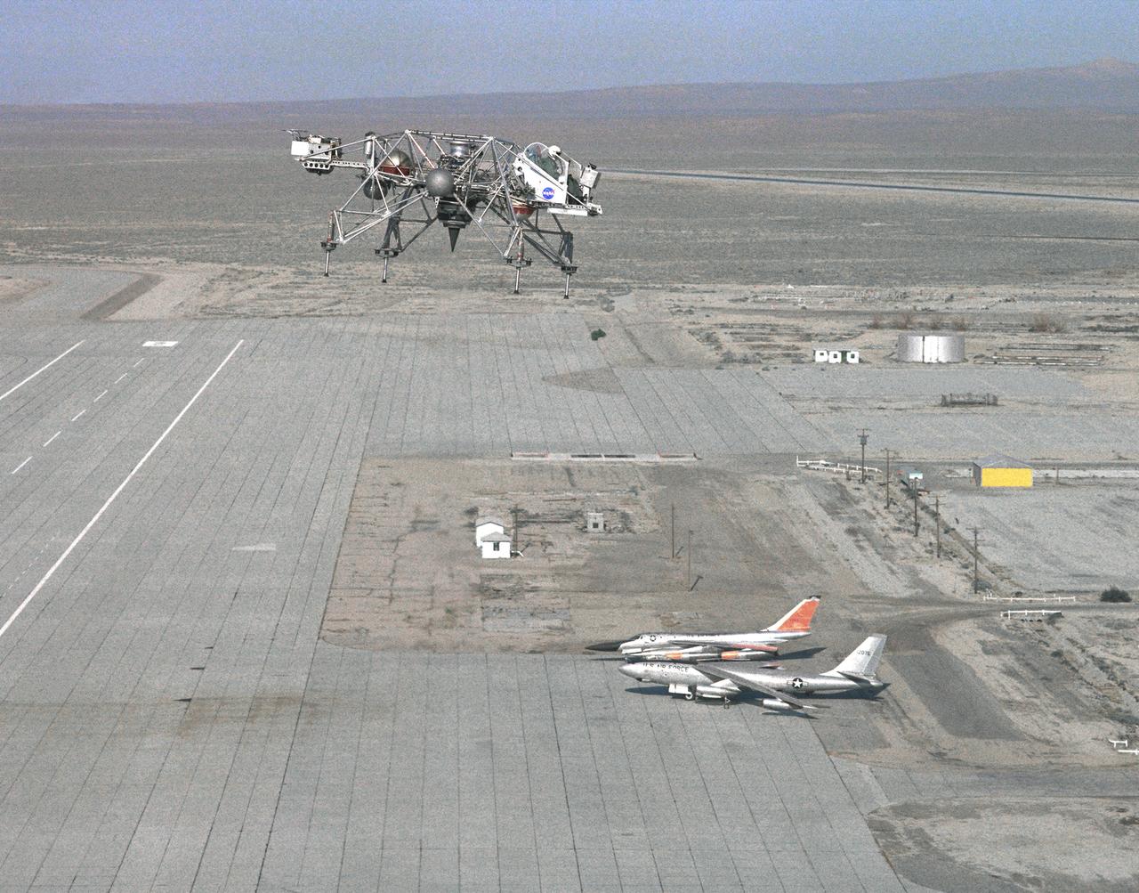
In this 1965 NASA Flight Reserch Center photograph the Lunar Landing Research Vehicle (LLRV) is shown at near maximum altitude over the south base at Edwards Air Force Base. When Apollo planning was underway in 1960, NASA was looking for a simulator to profile the descent to the moon's surface. Three concepts surfaced: an electronic simulator, a tethered device, and the ambitious Dryden contribution, a free-flying vehicle. All three became serious projects, but eventually the NASA Flight Research Center's (FRC) Landing Research Vehicle (LLRV) became the most significant one. Hubert M. Drake is credited with originating the idea, while Donald Bellman and Gene Matranga were senior engineers on the project, with Bellman, the project manager. Simultaneously, and independently, Bell Aerosystems Company, Buffalo, N.Y., a company with experience in vertical takeoff and landing (VTOL) aircraft, had conceived a similar free-flying simulator and proposed their concept to NASA headquarters. NASA Headquarters put FRC and Bell together to collaborate. The challenge was; to allow a pilot to make a vertical landing on Earth in a simulated moon environment, one sixth of the Earth's gravity and with totally transparent aerodynamic forces in a "free flight" vehicle with no tether forces acting on it. Built of tubular aluminum like a giant four-legged bedstead, the vehicle was to simulate a lunar landing profile from around 1500 feet to the moon's surface. To do this, the LLRV had a General Electric CF-700-2V turbofan engine mounted vertically in gimbals, with 4200 pounds of thrust. The engine, using JP-4 fuel, got the vehicle up to the test altitude and was then throttled back to support five-sixths of the vehicle's weight, simulating the reduced gravity of the moon. Two hydrogen-peroxide lift rockets with thrust that could be varied from 100 to 500 pounds handled the LLRV's rate of descent and horizontal translations. Sixteen smaller hydrogen-peroxide rockets, mounted in pairs, gav
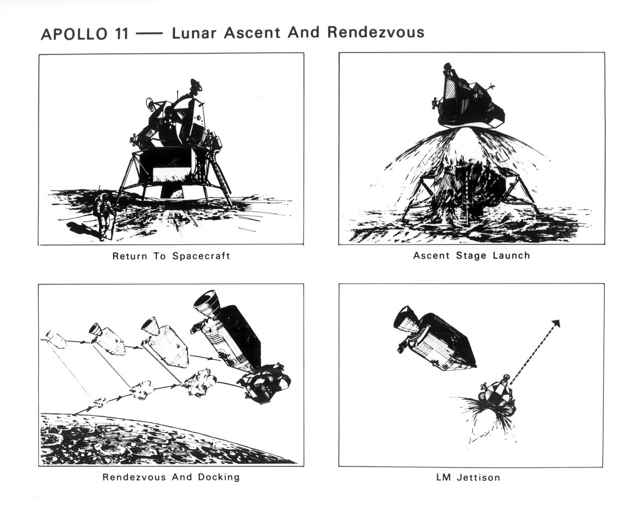
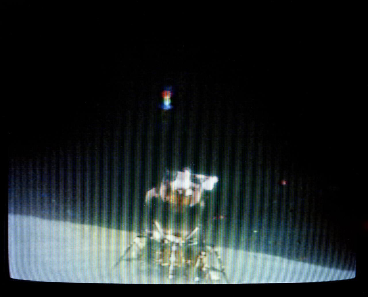
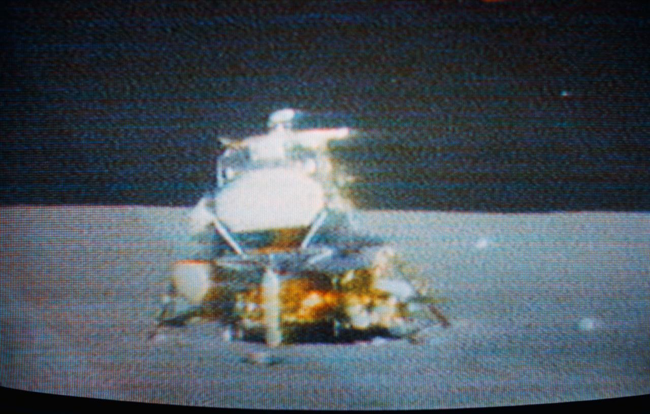
The Apollo 11 mission launched from the Kennedy Space Center (KSC) in Florida via the Marshall Space Flight Center (MSFC) developed Saturn V launch vehicle on July 16, 1969 and safely returned to Earth on July 24, 1969. Aboard the space craft were astronauts Neil A. Armstrong, commander; Michael Collins, Command Module (CM) pilot; and Edwin E. (Buzz) Aldrin Jr., Lunar Module (LM) pilot. With the success of Apollo 11, the national objective to land men on the Moon and return them safely to Earth had been accomplished. These sketches illustrate the steps taken when the astronauts left the Moon. After 2½ hours of surface exploration, astronauts Neil Armstrong and Edwin Aldrin returned to the Lunar Module (LM) “Eagle” for rest, eating, and checkout of the vehicle in preparation for liftoff. The ascent stage lifted off, using the descent stage as a launch pad. The ascent stage went into lunar orbit and moved in to dock with the orbiting CM “Columbia”. After Armstrong and Aldrin joined Collins in the CM, the engine of the LM ascent stage was fired to move it out of the same orbit.

Project LOLA. Test subject sitting at the controls: Project LOLA or Lunar Orbit and Landing Approach was a simulator built at Langley to study problems related to landing on the lunar surface. It was a complex project that cost nearly 2 million dollars. James Hansen wrote: This simulator was designed to provide a pilot with a detailed visual encounter with the lunar surface the machine consisted primarily of a cockpit, a closed-circuit TV system, and four large murals or scale models representing portions of the lunar surface as seen from various altitudes. The pilot in the cockpit moved along a track past these murals which would accustom him to the visual cues for controlling a spacecraft in the vicinity of the moon. Unfortunately, such a simulation--although great fun and quite aesthetic--was not helpful because flight in lunar orbit posed no special problems other than the rendezvous with the LEM, which the device did not simulate. Not long after the end of Apollo, the expensive machine was dismantled. (p. 379) Ellis J. White wrote in his paper, Discussion of Three Typical Langley Research Center Simulation Programs : A typical mission would start with the first cart positioned on model 1 for the translunar approach and orbit establishment. After starting the descent, the second cart is readied on model 2 and, at the proper time, when superposition occurs, the pilot s scene is switched from model 1 to model 2. then cart 1 is moved to and readied on model 3. The procedure continues until an altitude of 150 feet is obtained. The cabin of the LM vehicle has four windows which represent a 45 degree field of view. The projection screens in front of each window represent 65 degrees which allows limited head motion before the edges of the display can be seen. The lunar scene is presented to the pilot by rear projection on the screens with four Schmidt television projectors. The attitude orientation of the vehicle is represented by changing the lunar scene through the portholes determined by the scan pattern of four orthicons. The stars are front projected onto the upper three screens with a four-axis starfield generation (starball) mounted over the cabin and there is a separate starball for the low window. -- Published in James R. Hansen, Spaceflight Revolution: NASA Langley Research Center From Sputnik to Apollo, (Washington: NASA, 1995), p. 379 Ellis J. White, Discussion of Three Typical Langley Research Center Simulation Programs, Paper presented at the Eastern Simulation Council (EAI s Princeton Computation Center), Princeton, NJ, October 20, 1966.
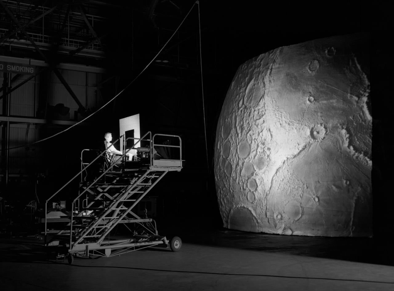
Test subject sitting at the controls: Project LOLA or Lunar Orbit and Landing Approach was a simulator built at Langley to study problems related to landing on the lunar surface. It was a complex project that cost nearly $2 million dollars. James Hansen wrote: "This simulator was designed to provide a pilot with a detailed visual encounter with the lunar surface; the machine consisted primarily of a cockpit, a closed-circuit TV system, and four large murals or scale models representing portions of the lunar surface as seen from various altitudes. The pilot in the cockpit moved along a track past these murals which would accustom him to the visual cues for controlling a spacecraft in the vicinity of the moon. Unfortunately, such a simulation--although great fun and quite aesthetic--was not helpful because flight in lunar orbit posed no special problems other than the rendezvous with the LEM, which the device did not simulate. Not long after the end of Apollo, the expensive machine was dismantled." (p. 379) Ellis J. White further described this simulator in his paper , "Discussion of Three Typical Langley Research Center Simulation Programs," (Paper presented at the Eastern Simulation Council (EAI's Princeton Computation Center), Princeton, NJ, October 20, 1966.) "A typical mission would start with the first cart positioned on model 1 for the translunar approach and orbit establishment. After starting the descent, the second cart is readied on model 2 and, at the proper time, when superposition occurs, the pilot's scene is switched from model 1 to model 2. then cart 1 is moved to and readied on model 3. The procedure continues until an altitude of 150 feet is obtained. The cabin of the LM vehicle has four windows which represent a 45 degree field of view. The projection screens in front of each window represent 65 degrees which allows limited head motion before the edges of the display can be seen. The lunar scene is presented to the pilot by rear projection on the screens with four Schmidt television projectors. The attitude orientation of the vehicle is represented by changing the lunar scene through the portholes determined by the scan pattern of four orthicons. The stars are front projected onto the upper three screens with a four-axis starfield generation (starball) mounted over the cabin and there is a separate starball for the low window." -- Published in James R. Hansen, Spaceflight Revolution: NASA Langley Research Center From Sputnik to Apollo, (Washington: NASA, 1995), p. 379.
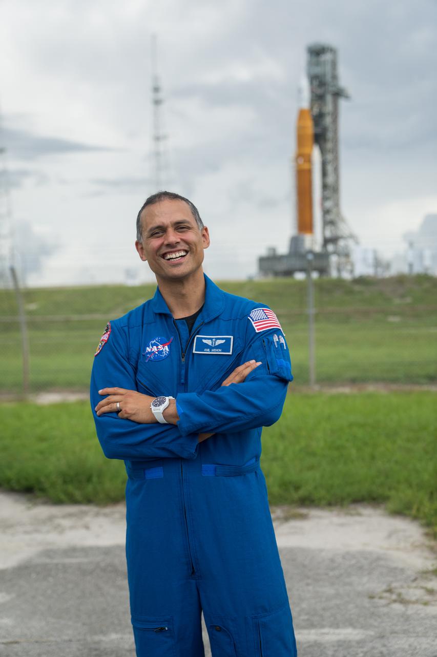
NASA astronaut candidate Anil Menon poses for a photograph in front of NASA’s Artemis I Space Launch System and Orion spacecraft atop the mobile launcher on the pad at Launch Complex 39B at the agency’s Kennedy Space Center in Florida on Sept. 2, 2022. The first in a series of increasingly complex missions, Artemis I will provide a foundation for human deep space exploration and demonstrate our commitment and capability to extend human presence to the Moon and beyond. The primary goal of Artemis I is to thoroughly test the integrated systems before crewed missions by operating the spacecraft in a deep space environment, testing Orion’s heat shield, and recovering the crew module after reentry, descent, and splashdown. In later missions, NASA will land the first woman and the first person of color on the surface of the Moon, paving the way for a long-term lunar presence and serving as a steppingstone on the way to Mars.
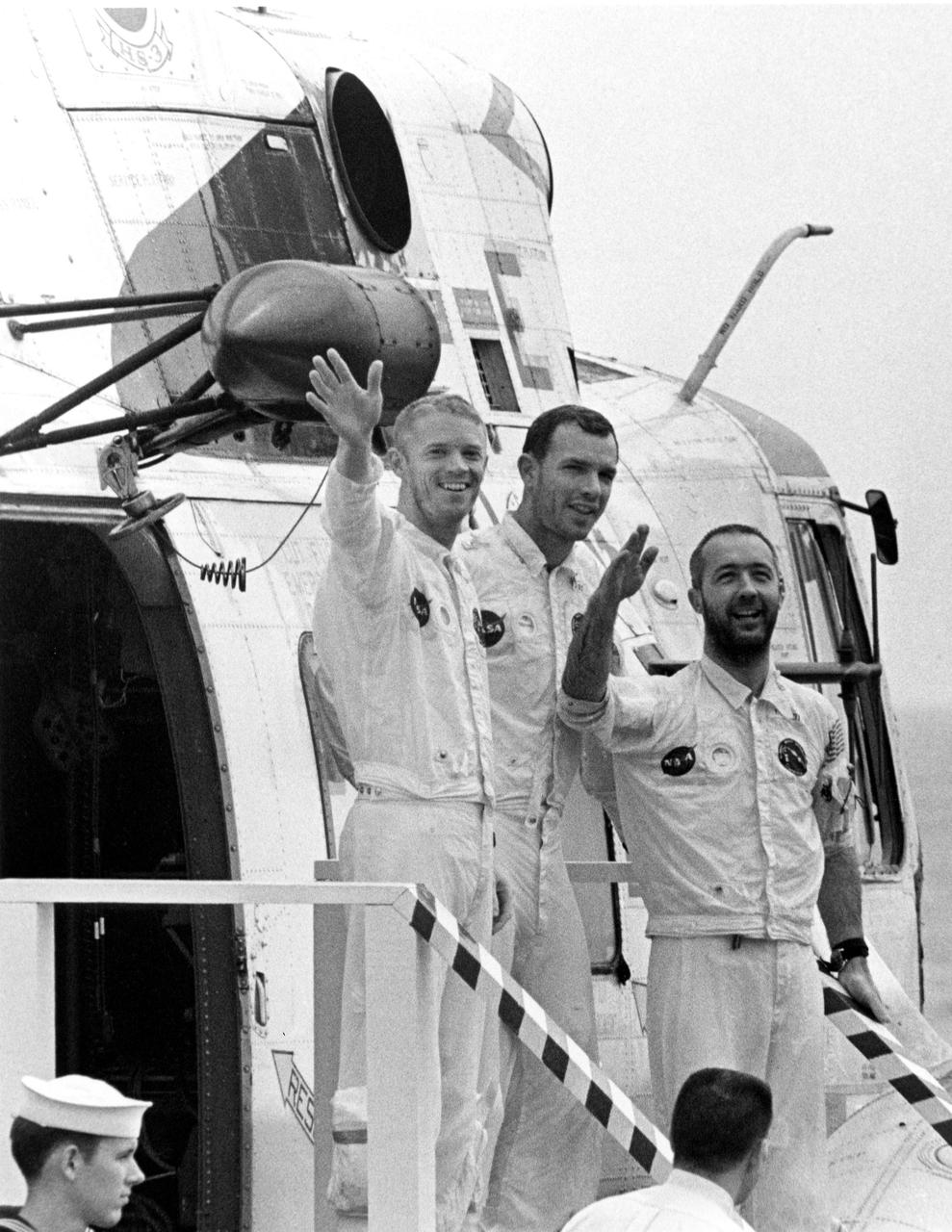
KENNEDY SPACE CENTER, FLA. -- One hour after their Apollo 9 spacecraft splashed down today in the Atlantic Ocean, waving astronauts, left to right, Russell L. Schweickart, David R. Scott and James A. McDivitt, descend stairway on to main deck of the USS Guadalcanal, prime recovery ship. The helicopter flew them from their impact point a short distance to the ship, originally positioned less than five miles from where they splashed down. The 10-day Earth orbital mission proved the feasibility of the lunar module for manned descent to the Moon's surface, scheduled to take place later this year. They wre launched March 3, 1969, from the Kennedy Space Center aboard an Apollo_Saturn V space vehicle. The National Aeronautics and Space Administration directs the Apollo program.
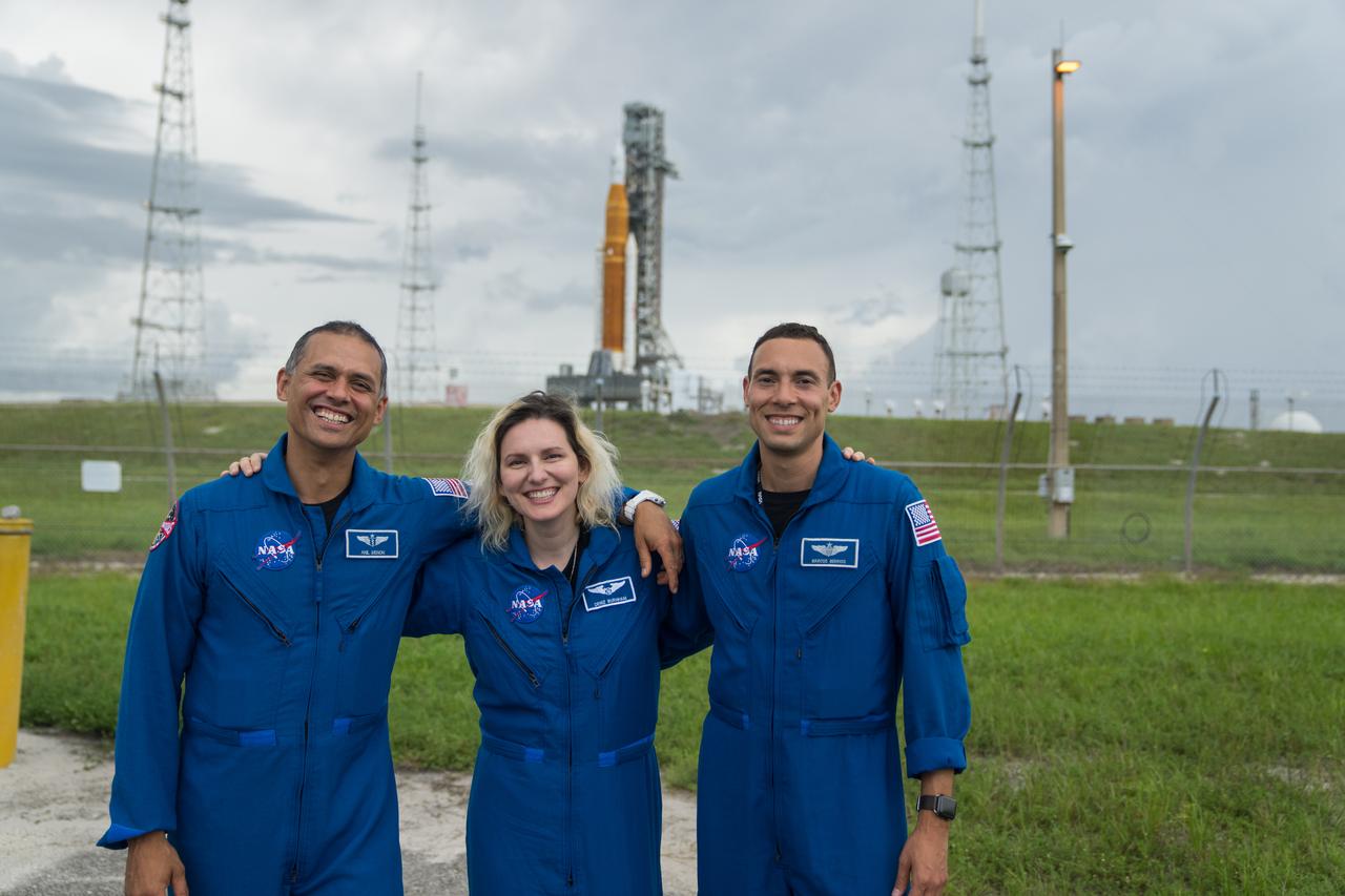
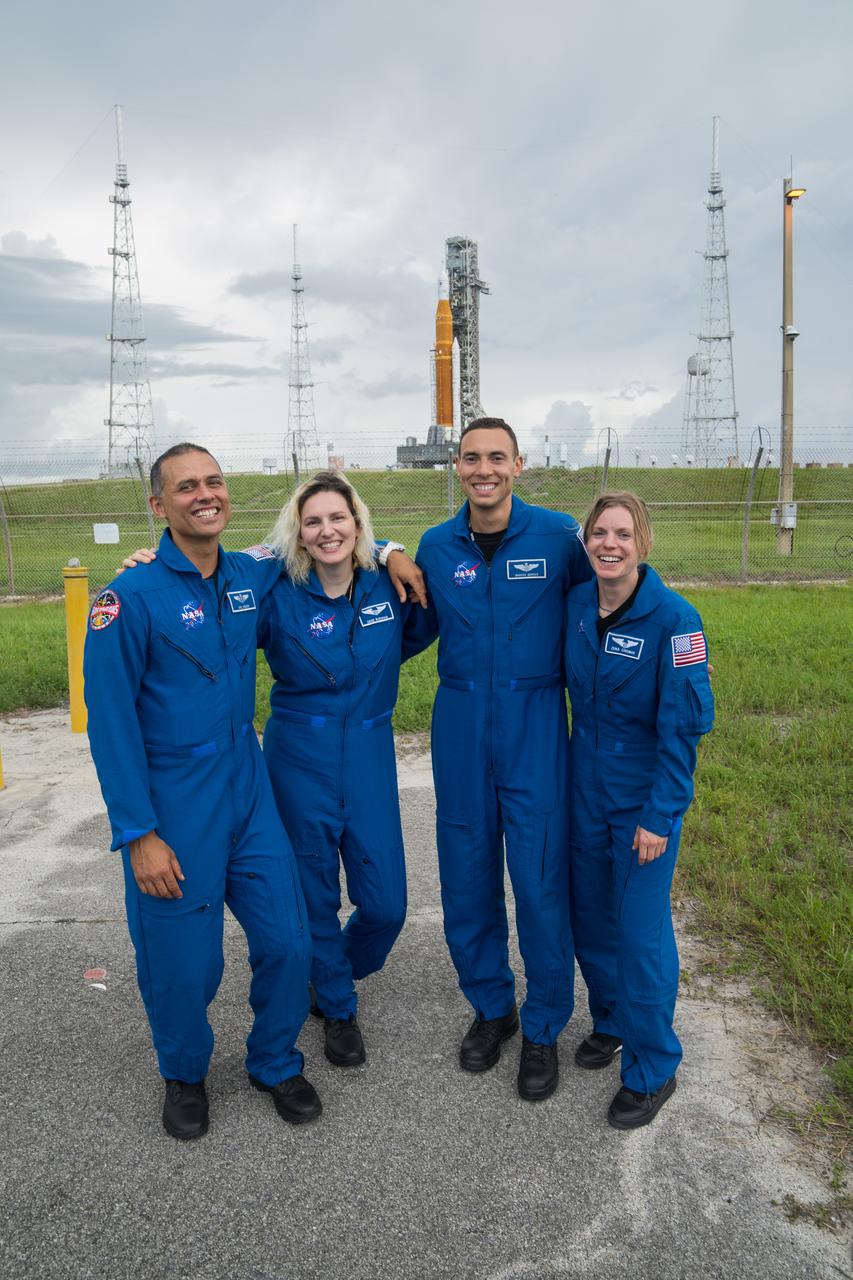
From left to right, NASA astronaut candidates Anil Menon, Deniz Burnham, and Marcos Berrios pose for a photograph in front of NASA’s Artemis I Space Launch System and Orion spacecraft atop the mobile launcher on the pad at Launch Complex 39B at the agency’s Kennedy Space Center in Florida on Sept. 2, 2022. The first in a series of increasingly complex missions, Artemis I will provide a foundation for human deep space exploration and demonstrate our commitment and capability to extend human presence to the Moon and beyond. The primary goal of Artemis I is to thoroughly test the integrated systems before crewed missions by operating the spacecraft in a deep space environment, testing Orion’s heat shield, and recovering the crew module after reentry, descent, and splashdown. In later missions, NASA will land the first woman and the first person of color on the surface of the Moon, paving the way for a long-term lunar presence and serving as a steppingstone on the way to Mars.
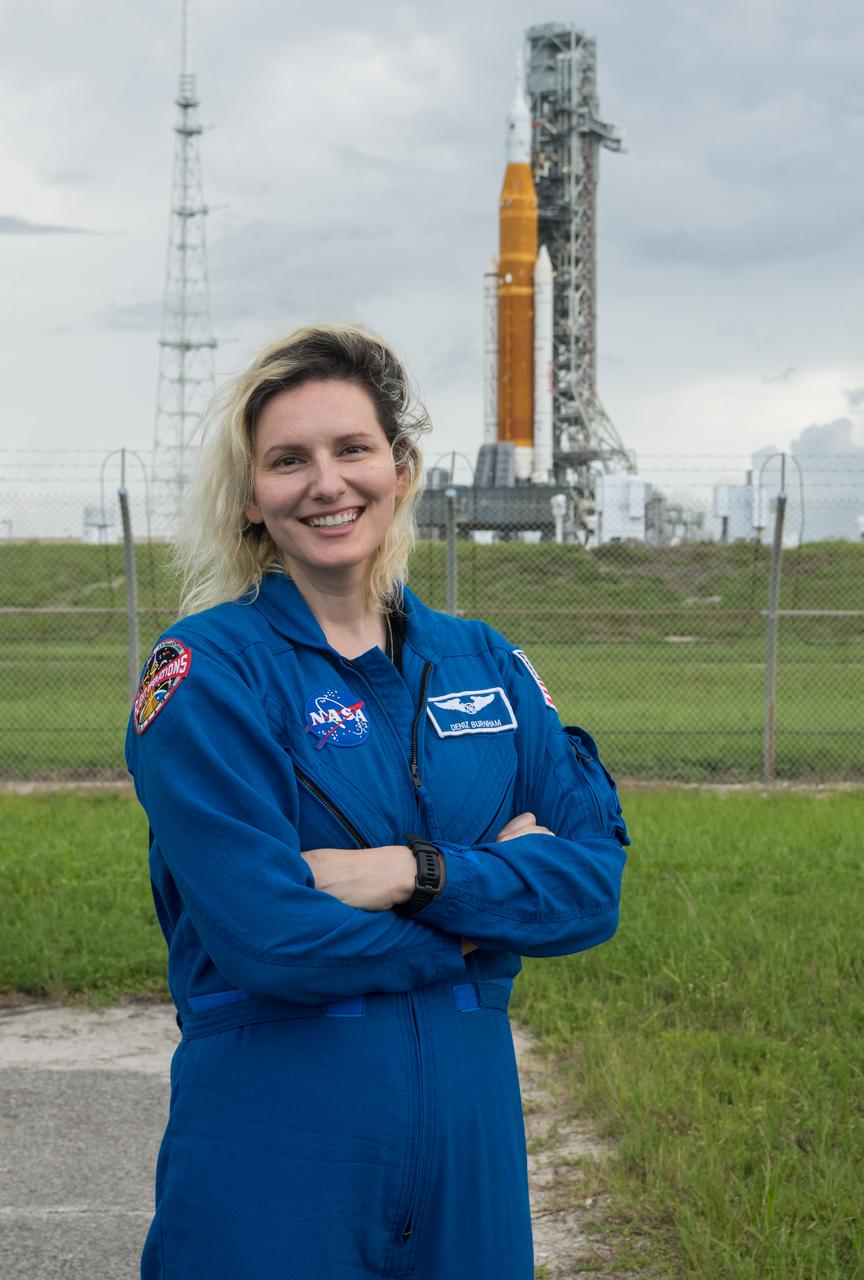
NASA astronaut candidate Deniz Burnham poses for a photograph in front of NASA’s Artemis I Space Launch System and Orion spacecraft atop the mobile launcher on the pad at Launch Complex 39B at the agency’s Kennedy Space Center in Florida on Sept. 2, 2022. The first in a series of increasingly complex missions, Artemis I will provide a foundation for human deep space exploration and demonstrate our commitment and capability to extend human presence to the Moon and beyond. The primary goal of Artemis I is to thoroughly test the integrated systems before crewed missions by operating the spacecraft in a deep space environment, testing Orion’s heat shield, and recovering the crew module after reentry, descent, and splashdown. In later missions, NASA will land the first woman and the first person of color on the surface of the Moon, paving the way for a long-term lunar presence and serving as a steppingstone on the way to Mars.
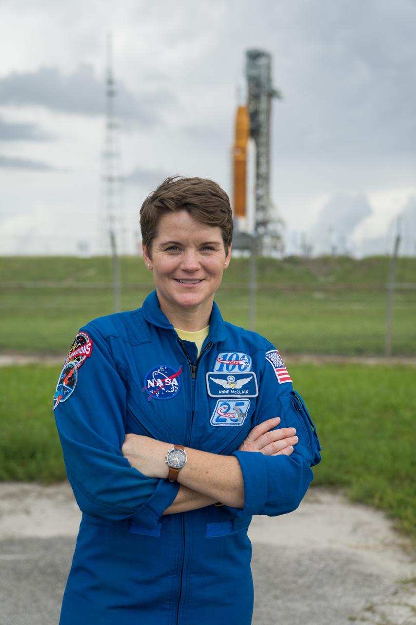
NASA astronaut Anne McClain poses for a photograph in front of NASA’s Artemis I Space Launch System and Orion spacecraft atop the mobile launcher on the pad at Launch Complex 39B at the agency’s Kennedy Space Center in Florida on Sept. 2, 2022. The first in a series of increasingly complex missions, Artemis I will provide a foundation for human deep space exploration and demonstrate our commitment and capability to extend human presence to the Moon and beyond. The primary goal of Artemis I is to thoroughly test the integrated systems before crewed missions by operating the spacecraft in a deep space environment, testing Orion’s heat shield, and recovering the crew module after reentry, descent, and splashdown. In later missions, NASA will land the first woman and the first person of color on the surface of the Moon, paving the way for a long-term lunar presence and serving as a steppingstone on the way to Mars.
From left to right, NASA astronaut candidates Anil Menon, Deniz Burnham, and Marcos Berrios, and NASA astronaut Zena Cardman pose for a photograph in front of NASA’s Artemis I Space Launch System and Orion spacecraft atop the mobile launcher on the pad at Launch Complex 39B at the agency’s Kennedy Space Center in Florida on Sept. 2, 2022. The first in a series of increasingly complex missions, Artemis I will provide a foundation for human deep space exploration and demonstrate our commitment and capability to extend human presence to the Moon and beyond. The primary goal of Artemis I is to thoroughly test the integrated systems before crewed missions by operating the spacecraft in a deep space environment, testing Orion’s heat shield, and recovering the crew module after reentry, descent, and splashdown. In later missions, NASA will land the first woman and the first person of color on the surface of the Moon, paving the way for a long-term lunar presence and serving as a steppingstone on the way to Mars.
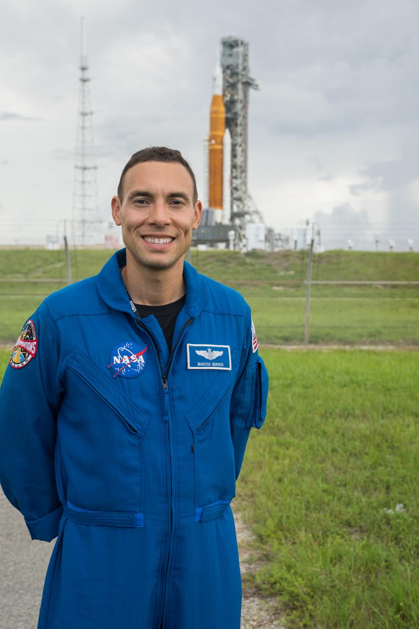
NASA astronaut candidate Marcos Berrios poses for a photograph in front of NASA’s Artemis I Space Launch System and Orion spacecraft atop the mobile launcher on the pad at Launch Complex 39B at the agency’s Kennedy Space Center in Florida on Sept. 2, 2022. The first in a series of increasingly complex missions, Artemis I will provide a foundation for human deep space exploration and demonstrate our commitment and capability to extend human presence to the Moon and beyond. The primary goal of Artemis I is to thoroughly test the integrated systems before crewed missions by operating the spacecraft in a deep space environment, testing Orion’s heat shield, and recovering the crew module after reentry, descent, and splashdown. In later missions, NASA will land the first woman and the first person of color on the surface of the Moon, paving the way for a long-term lunar presence and serving as a steppingstone on the way to Mars.
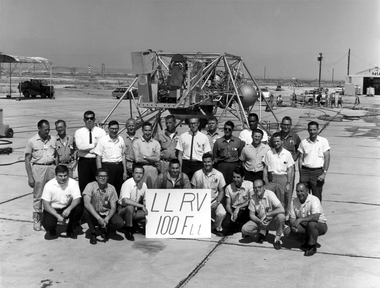
A group photo of the LLRV personnel following the program's 100th flight. The photo was taken at South Base, and was near the hangar first used by the original NACA group, at what was then called Muroc. When Apollo planning was underway in 1960, NASA was looking for a simulator to profile the descent to the moon's surface. Three concepts surfaced: an electronic simulator, a tethered device, and the ambitious Dryden contribution, a free-flying vehicle. All three became serious projects, but eventually the NASA Flight Research Center's (FRC) Landing Research Vehicle (LLRV) became the most significant one. Hubert M. Drake is credited with originating the idea, while Donald Bellman and Gene Matranga were senior engineers on the project, with Bellman, the project manager. Simultaneously, and independently, Bell Aerosystems Company, Buffalo, N.Y., a company with experience in vertical takeoff and landing (VTOL) aircraft, had conceived a similar free-flying simulator and proposed their concept to NASA headquarters. NASA Headquarters put FRC and Bell together to collaborate. The challenge was; to allow a pilot to make a vertical landing on Earth in a simulated moon environment, one sixth of the Earth's gravity and with totally transparent aerodynamic forces in a "free flight" vehicle with no tether forces acting on it. Built of tubular aluminum like a giant four-legged bedstead, the vehicle was to simulate a lunar landing profile from around 1500 feet to the moon's surface. To do this, the LLRV had a General Electric CF-700-2V turbofan engine mounted vertically in gimbals, with 4200 pounds of thrust. The engine, using JP-4 fuel, got the vehicle up to the test altitude and was then throttled back to support five-sixths of the vehicle's weight, simulating the reduced gravity of the moon. Two hydrogen-peroxide lift rockets with thrust that could be varied from 100 to 500 pounds handled the LLRV's rate of descent and horizontal translations. Sixteen smaller hydrogen-peroxide r
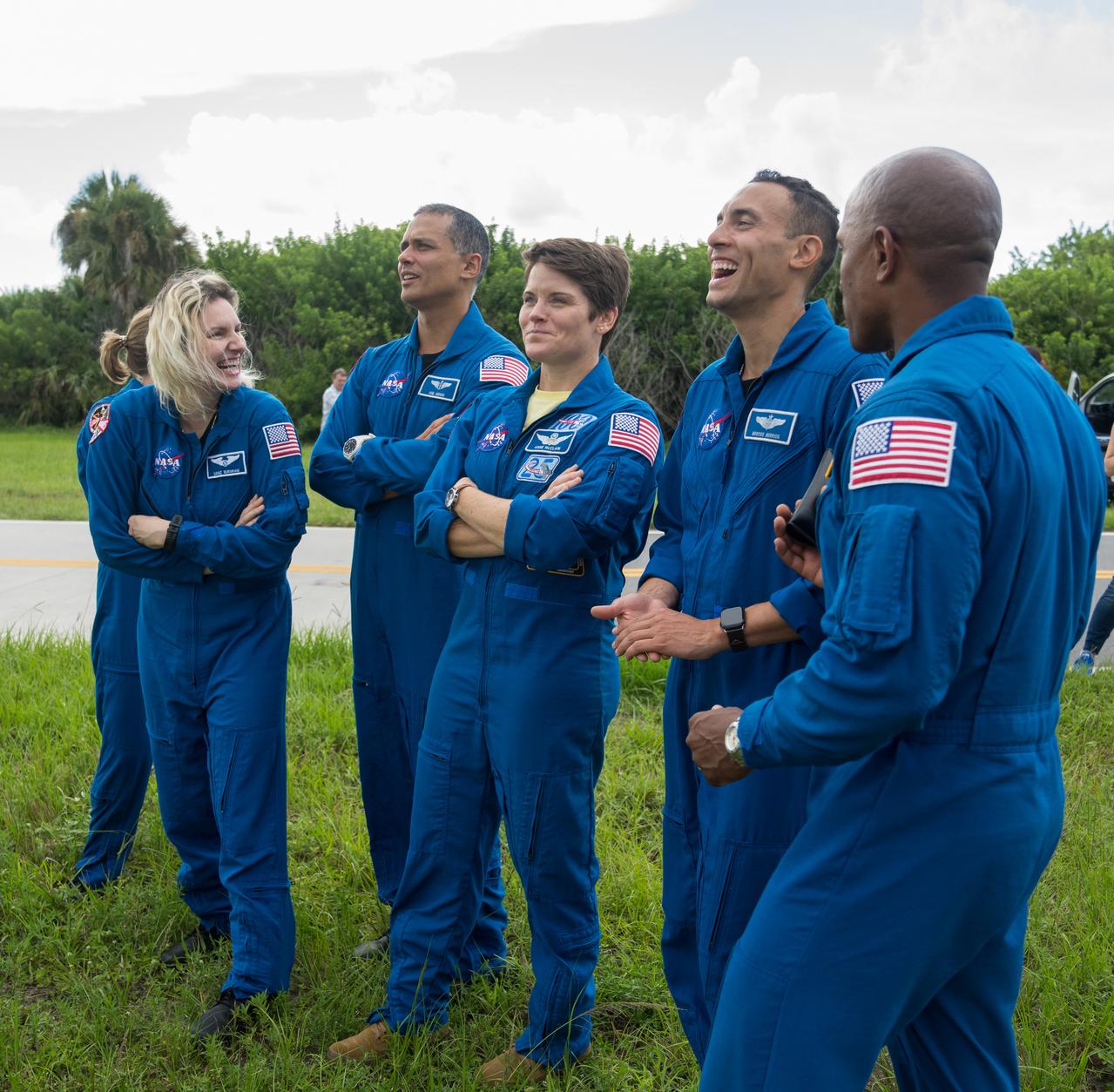
NASA astronauts and astronaut candidates view NASA’s Artemis I Space Launch System and Orion spacecraft atop the mobile launcher on the pad at Launch Complex 39B at the agency’s Kennedy Space Center in Florida on Sept. 2, 2022. The astronauts are, from left to right: Zena Cardman (partially obscured), NASA astronaut; Deniz Burnham and Anil Menon, NASA astronaut candidates; Anne McClain, NASA astronaut; Marcos Berrios, NASA astronaut candidate; and Victor Glover, NASA astronaut. The first in a series of increasingly complex missions, Artemis I will provide a foundation for human deep space exploration and demonstrate our commitment and capability to extend human presence to the Moon and beyond. The primary goal of Artemis I is to thoroughly test the integrated systems before crewed missions by operating the spacecraft in a deep space environment, testing Orion’s heat shield, and recovering the crew module after reentry, descent, and splashdown. In later missions, NASA will land the first woman and the first person of color on the surface of the Moon, paving the way for a long-term lunar presence and serving as a steppingstone on the way to Mars.

NASA’s Space Launch System (SLS) rocket with the Orion spacecraft atop a mobile launcher is seen through the windows of Firing Room 1 in the Rocco A. Petrone Launch Control Center as it rolls out of High Bay 3 of the Vehicle Assembly Building to Launch Complex 39B, on Tuesday, Aug. 16, 2022, ahead of the agency’s Artemis I flight test. The fully stacked and integrated SLS rocket and Orion spacecraft is scheduled to liftoff on Monday, Aug. 29. The first in a series of increasingly complex missions, Artemis I will provide a foundation for human deep space exploration and demonstrate our commitment and capability to extend human presence to the Moon and beyond. The primary goal of Artemis I is to thoroughly test the integrated systems before crewed missions by launching Orion atop the SLS rocket, operating the spacecraft in a deep space environment, testing Orion’s heat shield, and recovering the crew module after reentry, descent, and splashdown. In later missions, NASA will land the first woman and the first person of color on the surface of the Moon, paving the way for a long-term lunar presence and serving as a steppingstone on the way to Mars.
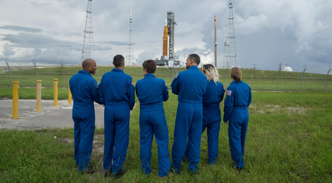
NASA astronauts and astronaut candidates view NASA’s Artemis I Space Launch System and Orion spacecraft atop the mobile launcher on the pad at Launch Complex 39B at the agency’s Kennedy Space Center in Florida on Sept. 2, 2022. The astronauts are, from left to right: Victor Glover, NASA astronaut; Marcos Berrios, NASA astronaut candidate; Anne McClain, NASA astronaut; Anil Menon and Deniz Burnham, NASA astronaut candidates; and Zena Cardman, NASA astronaut. The first in a series of increasingly complex missions, Artemis I will provide a foundation for human deep space exploration and demonstrate our commitment and capability to extend human presence to the Moon and beyond. The primary goal of Artemis I is to thoroughly test the integrated systems before crewed missions by operating the spacecraft in a deep space environment, testing Orion’s heat shield, and recovering the crew module after reentry, descent, and splashdown. In later missions, NASA will land the first woman and the first person of color on the surface of the Moon, paving the way for a long-term lunar presence and serving as a steppingstone on the way to Mars.
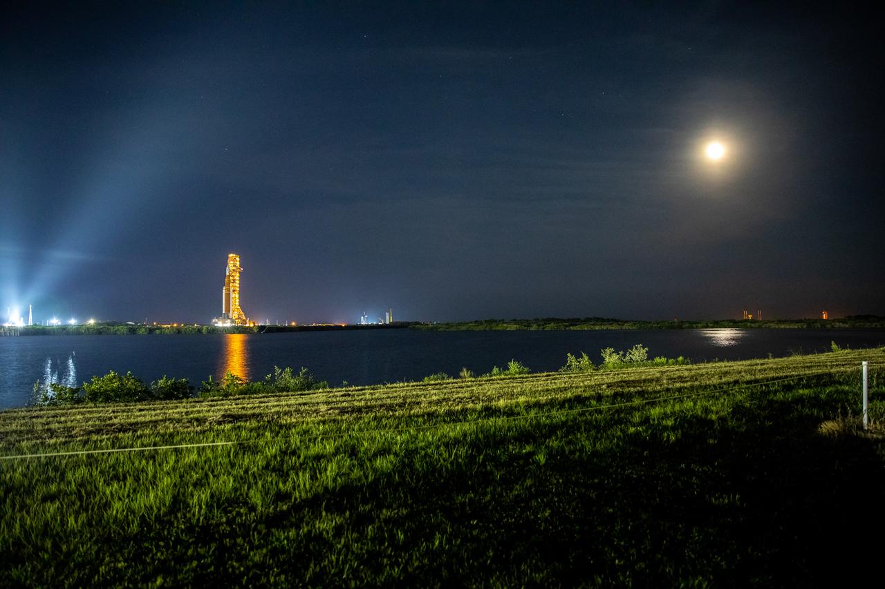
NASA’s Space Launch System (SLS) rocket, with the Orion capsule atop, slowly makes its way along the crawlerway at the agency’s Kennedy Space Center in Florida on Tuesday, Aug. 16, 2022/Wednesday, Aug. 17, 2022. Carried atop the crawler-transporter 2, NASA’s Moon rocket is venturing the 4.2 miles from the Vehicle Assembly Building to Launch Complex 39B ahead of the first flight test of the fully stacked and integrated SLS rocket and Orion spacecraft, scheduled to liftoff on Monday, Aug. 29. The first in a series of increasingly complex missions, Artemis I will provide a foundation for human deep space exploration and demonstrate our commitment and capability to extend human presence to the Moon and beyond. The primary goal of Artemis I is to thoroughly test the integrated systems before crewed missions by launching Orion atop the SLS rocket, operating the spacecraft in a deep space environment, testing Orion’s heat shield, and recovering the crew module after reentry, descent, and splashdown. In later missions, NASA will land the first woman and the first person of color on the surface of the Moon, paving the way for a long-term lunar presence and serving as a steppingstone on the way to Mars.
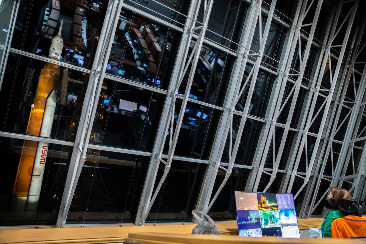
NASA Launch Director Charlie Blackwell-Thompson watches the agency’s Space Launch System (SLS) rocket with the Orion spacecraft atop a mobile launcher through the windows of Firing Room 1 in the Rocco A. Petrone Launch Control Center as it rolls out of High Bay 3 of the Vehicle Assembly Building to Launch Complex 39B, on Tuesday, Aug. 16, 2022, ahead of the agency’s Artemis I flight test. The fully stacked and integrated SLS rocket and Orion spacecraft is scheduled to liftoff on Monday, Aug. 29. The first in a series of increasingly complex missions, Artemis I will provide a foundation for human deep space exploration and demonstrate our commitment and capability to extend human presence to the Moon and beyond. The primary goal of Artemis I is to thoroughly test the integrated systems before crewed missions by launching Orion atop the SLS rocket, operating the spacecraft in a deep space environment, testing Orion’s heat shield, and recovering the crew module after reentry, descent, and splashdown. In later missions, NASA will land the first woman and the first person of color on the surface of the Moon, paving the way for a long-term lunar presence and serving as a steppingstone on the way to Mars.
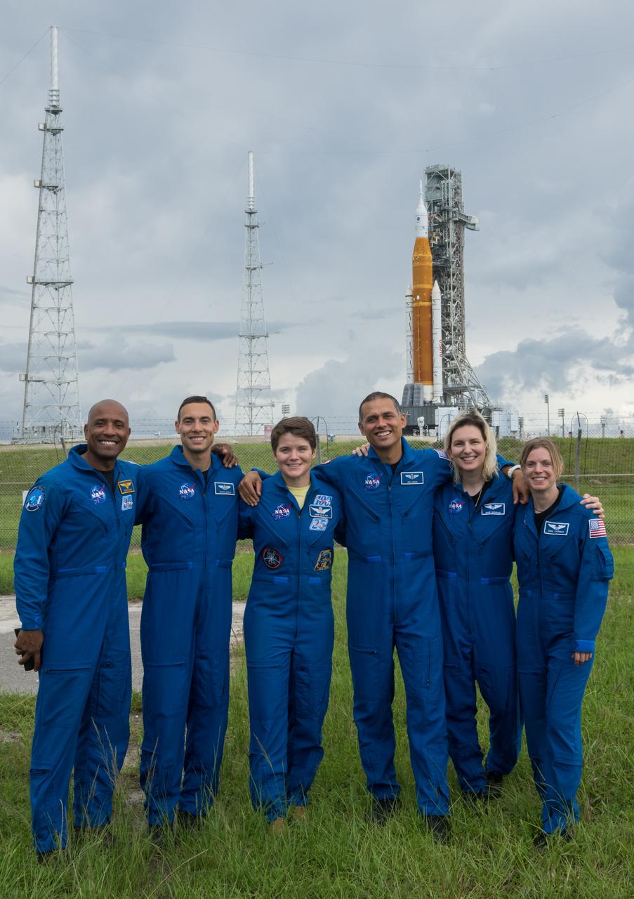
NASA astronauts and astronaut candidates pose for a photograph in front of NASA’s Artemis I Space Launch System and Orion spacecraft atop the mobile launcher on the pad at Launch Complex 39B at the agency’s Kennedy Space Center in Florida on Sept. 2, 2022. The astronauts are, from left to right: Victor Glover, NASA astronaut; Marcos Berrios, NASA astronaut candidate; Anne McClain, NASA astronaut; Anil Menon and Deniz Burnham, NASA astronaut candidates; and Zena Cardman, NASA astronaut. The first in a series of increasingly complex missions, Artemis I will provide a foundation for human deep space exploration and demonstrate our commitment and capability to extend human presence to the Moon and beyond. The primary goal of Artemis I is to thoroughly test the integrated systems before crewed missions by operating the spacecraft in a deep space environment, testing Orion’s heat shield, and recovering the crew module after reentry, descent, and splashdown. In later missions, NASA will land the first woman and the first person of color on the surface of the Moon, paving the way for a long-term lunar presence and serving as a steppingstone on the way to Mars.

NASA Launch Director Charlie Blackwell-Thompson monitors rollout operations from her console as the agency’s Space Launch System (SLS) rocket with the Orion spacecraft atop a mobile launcher is visible through the windows of Firing Room 1 in the Rocco A. Petrone Launch Control Center as it rolls out of High Bay 3 of the Vehicle Assembly Building to Launch Complex 39B, on Tuesday, Aug. 16, 2022, ahead of the agency’s Artemis I flight test. The fully stacked and integrated SLS rocket and Orion spacecraft is scheduled to liftoff on Monday, Aug. 29. The first in a series of increasingly complex missions, Artemis I will provide a foundation for human deep space exploration and demonstrate our commitment and capability to extend human presence to the Moon and beyond. The primary goal of Artemis I is to thoroughly test the integrated systems before crewed missions by launching Orion atop the SLS rocket, operating the spacecraft in a deep space environment, testing Orion’s heat shield, and recovering the crew module after reentry, descent, and splashdown. In later missions, NASA will land the first woman and the first person of color on the surface of the Moon, paving the way for a long-term lunar presence and serving as a steppingstone on the way to Mars.
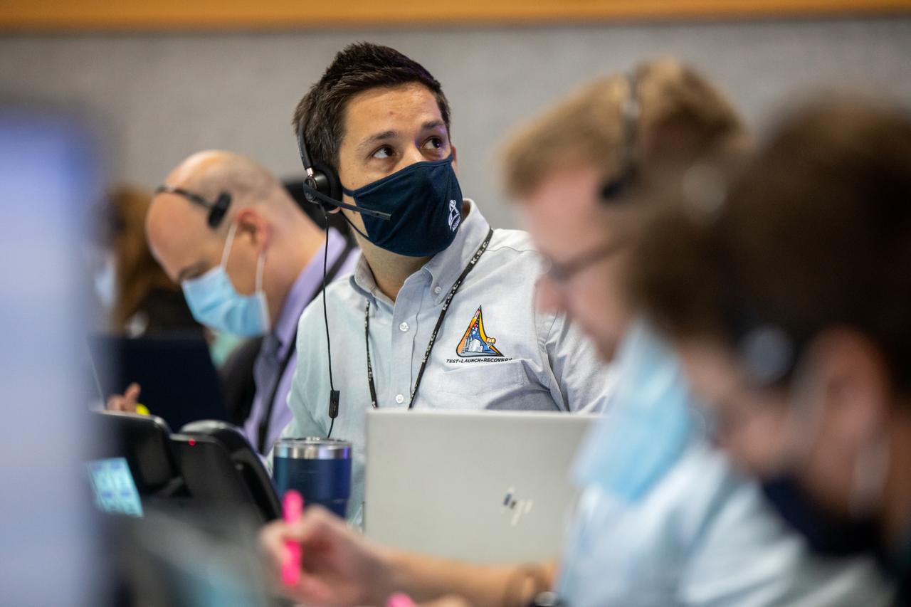
NASA Test Director Dan Florez watches the agency’s Space Launch System (SLS) rocket with the Orion spacecraft through the windows of Firing Room 1 in the Rocco A. Petrone Launch Control Center atop a mobile launcher as it rolls out of High Bay 3 of the Vehicle Assembly Building to Launch Complex 39B, on Tuesday, Aug. 16, 2022, ahead of the agency’s Artemis I flight test. The fully stacked and integrated SLS rocket and Orion spacecraft is scheduled to liftoff on Monday, Aug. 29. The first in a series of increasingly complex missions, Artemis I will provide a foundation for human deep space exploration and demonstrate our commitment and capability to extend human presence to the Moon and beyond. The primary goal of Artemis I is to thoroughly test the integrated systems before crewed missions by launching Orion atop the SLS rocket, operating the spacecraft in a deep space environment, testing Orion’s heat shield, and recovering the crew module after reentry, descent, and splashdown. In later missions, NASA will land the first woman and the first person of color on the surface of the Moon, paving the way for a long-term lunar presence and serving as a steppingstone on the way to Mars.
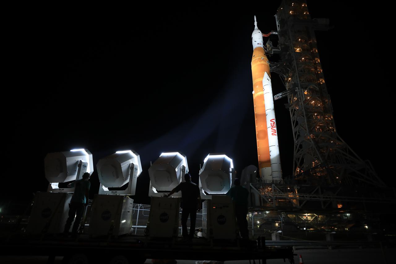
NASA’s Space Launch System (SLS) rocket, with the Orion capsule atop, slowly makes its way along the crawlerway at the agency’s Kennedy Space Center in Florida on Tuesday, Aug. 16, 2022/Wednesday, Aug. 17, 2022. Carried atop the crawler-transporter 2, NASA’s Moon rocket is venturing the 4.2 miles from the Vehicle Assembly Building to Launch Complex 39B ahead of the first flight test of the fully stacked and integrated SLS rocket and Orion spacecraft, scheduled to liftoff on Monday, Aug. 29. The first in a series of increasingly complex missions, Artemis I will provide a foundation for human deep space exploration and demonstrate our commitment and capability to extend human presence to the Moon and beyond. The primary goal of Artemis I is to thoroughly test the integrated systems before crewed missions by launching Orion atop the SLS rocket, operating the spacecraft in a deep space environment, testing Orion’s heat shield, and recovering the crew module after reentry, descent, and splashdown. In later missions, NASA will land the first woman and the first person of color on the surface of the Moon, paving the way for a long-term lunar presence and serving as a steppingstone on the way to Mars.
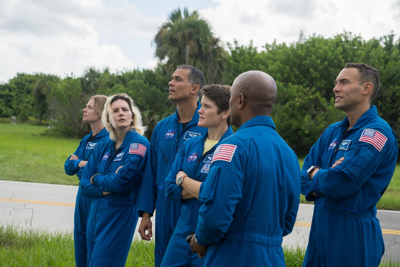
NASA astronauts and astronaut candidates view NASA’s Artemis I Space Launch System and Orion spacecraft atop the mobile launcher on the pad at Launch Complex 39B at the agency’s Kennedy Space Center in Florida on Sept. 2, 2022. The astronauts are, from left to right: Zena Cardman, NASA astronaut; Deniz Burnham and Anil Menon, NASA astronaut candidates; Anne McClain, NASA astronaut; Marcos Berrios, NASA astronaut candidate; and Victor Glover, NASA astronaut. The first in a series of increasingly complex missions, Artemis I will provide a foundation for human deep space exploration and demonstrate our commitment and capability to extend human presence to the Moon and beyond. The primary goal of Artemis I is to thoroughly test the integrated systems before crewed missions by operating the spacecraft in a deep space environment, testing Orion’s heat shield, and recovering the crew module after reentry, descent, and splashdown. In later missions, NASA will land the first woman and the first person of color on the surface of the Moon, paving the way for a long-term lunar presence and serving as a steppingstone on the way to Mars.