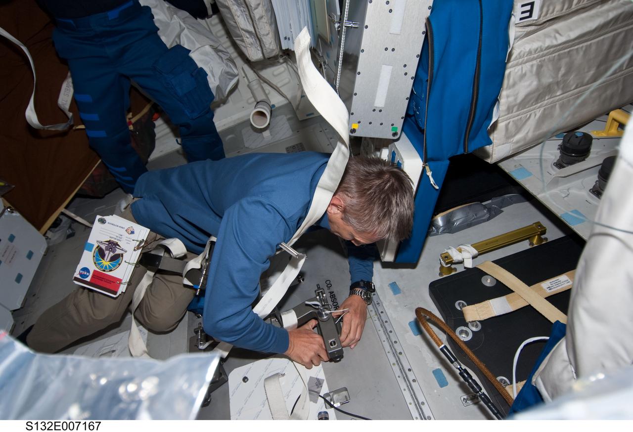
S132-E-007167 (15 May 2010) --- NASA astronaut Piers Sellers, STS-132 mission specialist, works at the Carbon Dioxide absorber panel door on the middeck of the Earth-orbiting space shuttle Atlantis during Flight Day 2 activities. Photo credit: NASA or National Aeronautics and Space Administration
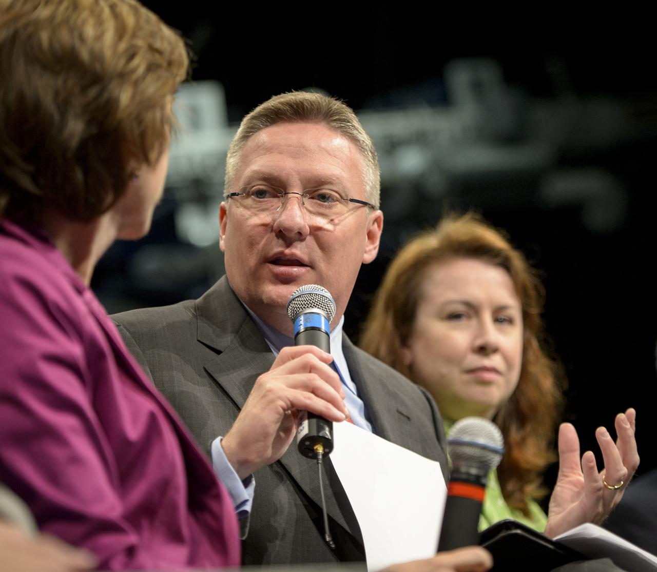
Tom Costello from NBC News moderates a panel discussion titled "Sally Ride: How Her Historic Space Mission Opened Doors for Women in Science" at the National Air and Space Museum on Friday, May 17, 2013 in Washington. Photo Credit: (NASA/Bill Ingalls)
Tom Costello from NBC News moderates a panel discussion titled "Sally Ride: How Her Historic Space Mission Opened Doors for Women in Science" at the National Air and Space Museum on Friday, May 17, 2013 in Washington. Photo Credit: (NASA/Bill Ingalls)
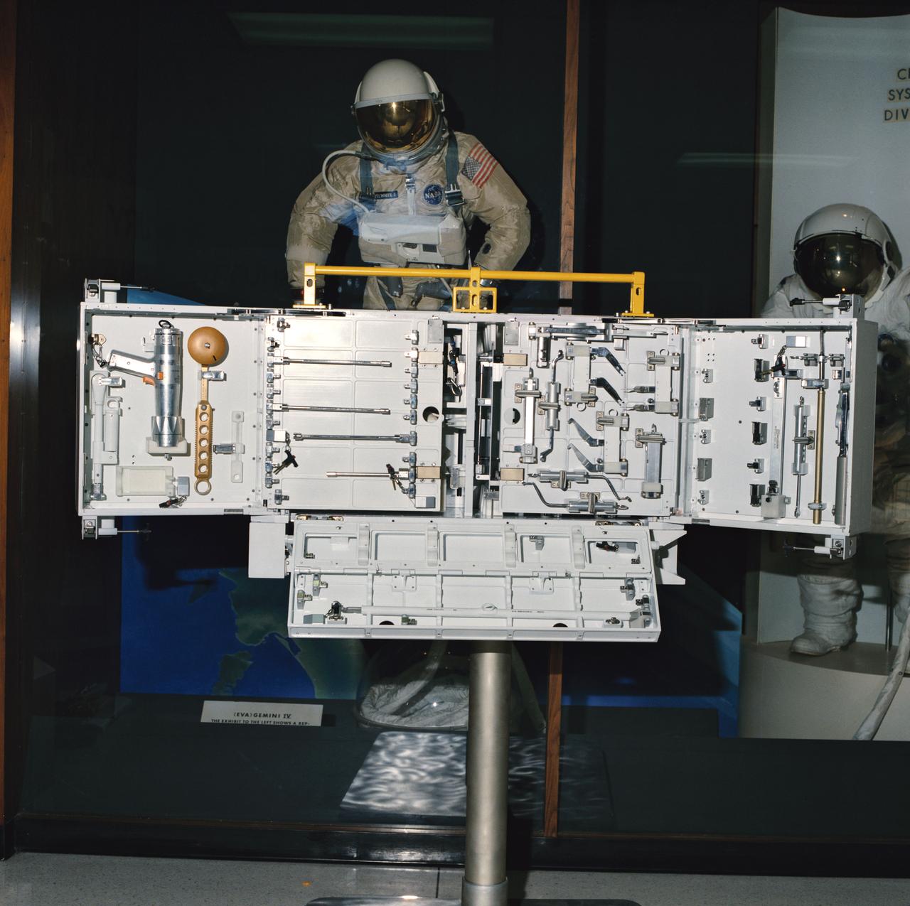
S87-49426 (1987) --- The Hubble Space Telescope (HST) tool box provides stowage of individual tools, tool boards and tool caddies required for maintenance of the telescope. The basic box design was revised from the LEASAT (U.S. Navy) equipment stowage container. It can be mounted to a base plate or back plate depending on the mission location requirements. A four-point latching system secured with pip pins is used to latch the tool box doors for launch. Various other latches are designed into the door panels and tool mounting locations for tool retention. The box consists of aluminum sides and base, a dividing wall and deep doors. Along three sides there are handrails by which STS-61 extravehicular activity (EVA) crew members can translate themselves or brace themselves when stowing and unstowing equipment.
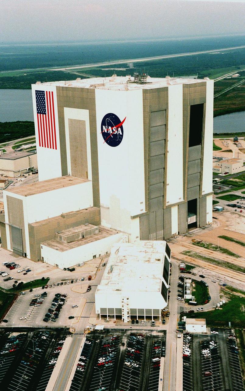
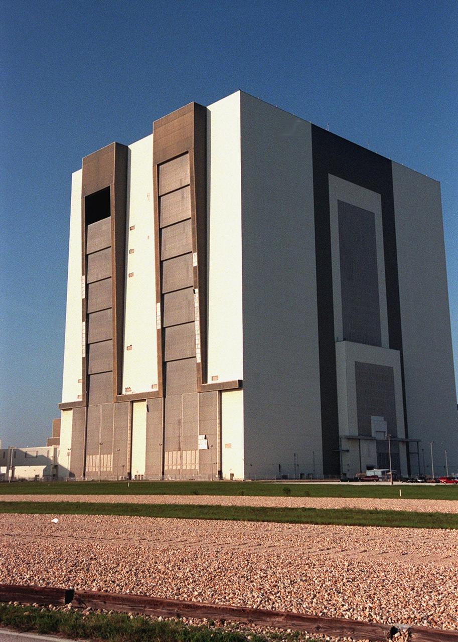
KENNEDY SPACE CENTER, FLA. -- Looking northwest, the Vehicle Assembly Building (VAB) in the Launch Complex 39 area of KSC can be seen with its new coat of paint, along with newly painted American flag and NASA logo. The improved look was finished in time to honor NASA's 40th anniversary on Oct. 1. In order to do the job, workers were suspended on platforms from the top of the 525-foot-high VAB. One of the world's largest buildings by volume, the VAB is the last stop for the Shuttle before rollout to the launch pad. Integration and stacking of the complete Space Shuttle vehicle (orbiter, two solid rocket boosters and the external tank) takes place in High Bays 1 or 3. The High Bay doors (shown partially open), four in all, are 456 feet high. The low-door section, 114 feet high, has four panels that move horizontally. The upper section, 342 feet high, has seven panels that move vertically. It takes about 45 minutes to open all panels. Beyond the VAB is the Shuttle Landing Facility (SLF) and Merritt Island National Wildlife Refuge. The SLF is used for end-of-mission orbiter landings, and also military and civilian cargo carriers, astronauts' T-38 trainers, Shuttle Training Aircraft, and helicopters
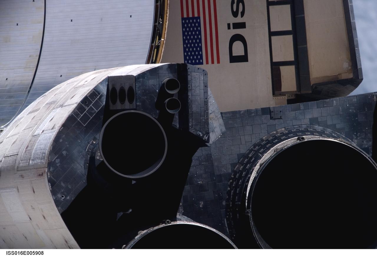
ISS016-E-005908 (25 Oct. 2007) --- A close-up view of Space Shuttle Discovery's tail section is featured in this image photographed by an Expedition 16 crewmember during a backflip maneuver performed by the approaching visitors (STS-120) to the International Space Station. The image provides partial views of the shuttle's main engines, orbital maneuvering system (OMS) pods, a portion of the payload bay door panels and the shuttle's wings.
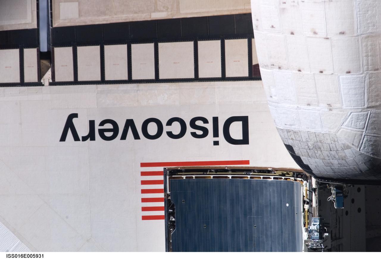
ISS016-E-005931 (25 Oct. 2007) --- A close-up view of Space Shuttle Discovery's wing section is provided by this image photographed by an Expedition 16 crewmember during a backflip maneuver performed by the approaching visitors (STS-120) to the International Space Station. Also visible are partial views of the orbital maneuvering system (OMS) pods and a portion of the payload bay door panels.
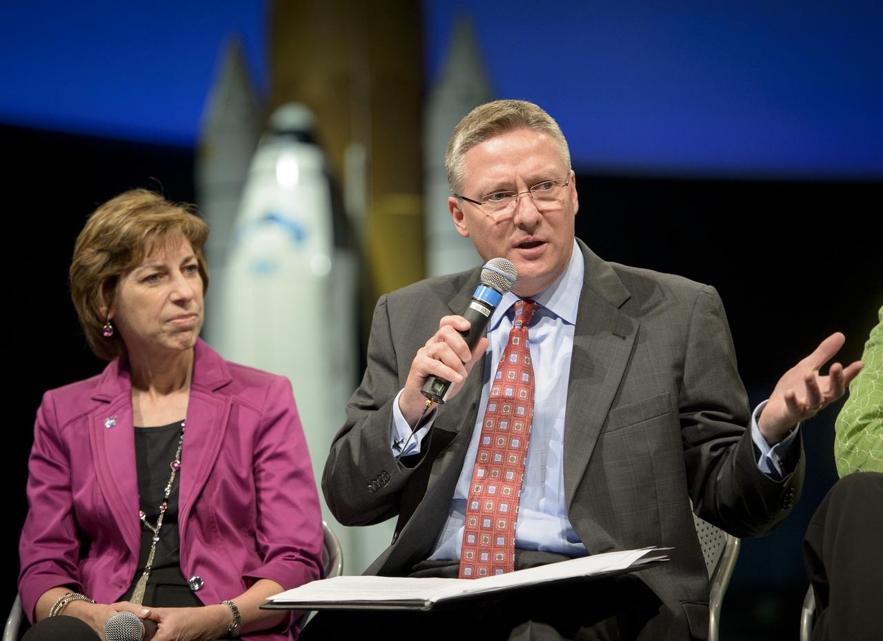
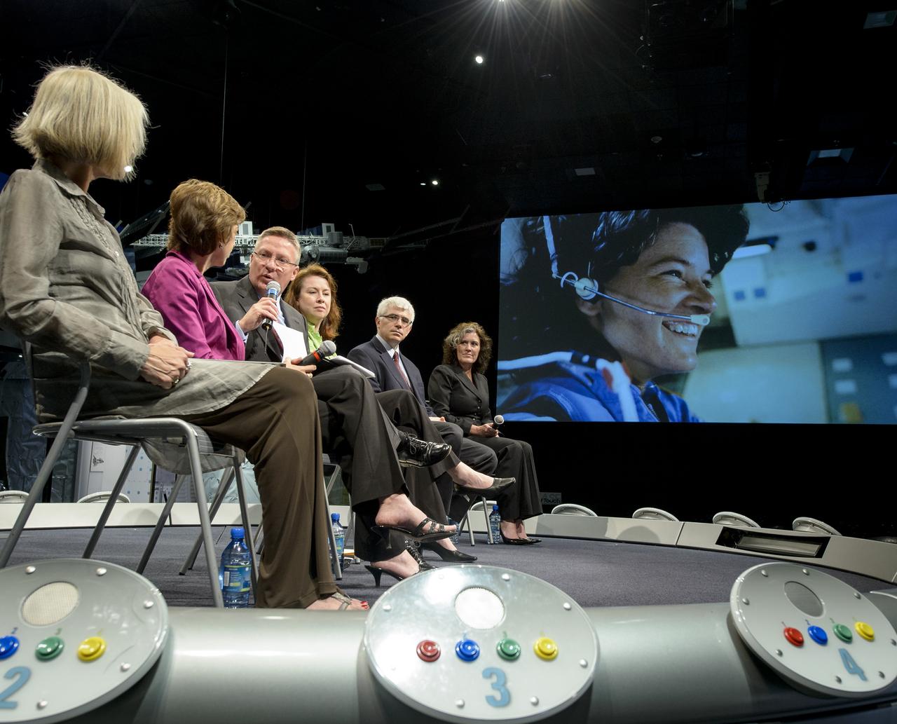
Tom Costello from NBC News moderates a panel discussion titled "Sally Ride: How Her Historic Space Mission Opened Doors for Women in Science" as Director of the NASA Johnson Space Center Ellen Ochoa looks on at the National Air and Space Museum on Friday, May 17, 2013 in Washington. Photo Credit: (NASA/Bill Ingalls)
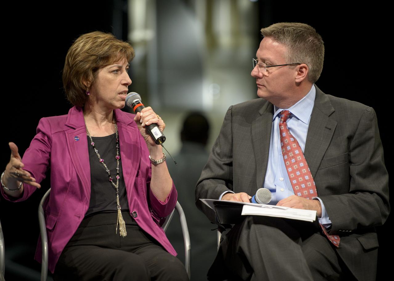
Director of the NASA Johnson Space Center Ellen Ochoa talks as Tom Costello from NBC News moderates a panel discussion titled "Sally Ride: How Her Historic Space Mission Opened Doors for Women in Science" at the National Air and Space Museum on Friday, May 17, 2013 in Washington. Photo Credit: (NASA/Bill Ingalls)
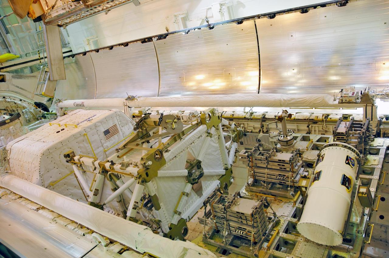
KENNEDY SPACE CENTER, FLA. -- With the payload successfully installed inside, the payload bay doors on Space Shuttle Discovery are closing. Seen here are the SPACEHAB module at left, the P5 truss in the center, service module debris panels and the Space Test Program experiment canister on the integrated cargo carrier at right. The shuttle is on Launch Pad 39B, ready for launch on mission STS-116 scheduled no earlier than Dec. 7. Photo credit: NASA/Dimitri Gerondidakis
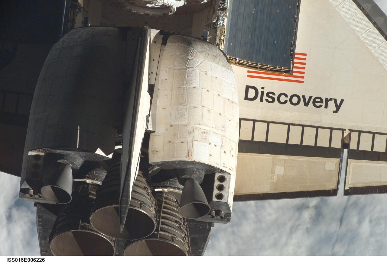
ISS016-E-006226 (25 Oct. 2007) --- Space Shuttle Discovery's tail section is featured in this close-up image photographed by an Expedition 16 crewmember during a backflip maneuver performed by the approaching visitors (STS-120) to the International Space Station. The image provides partial views of the shuttle's main engines, starboard wing section, orbital maneuvering system (OMS) pods, vertical stabilizer and payload bay door panels.
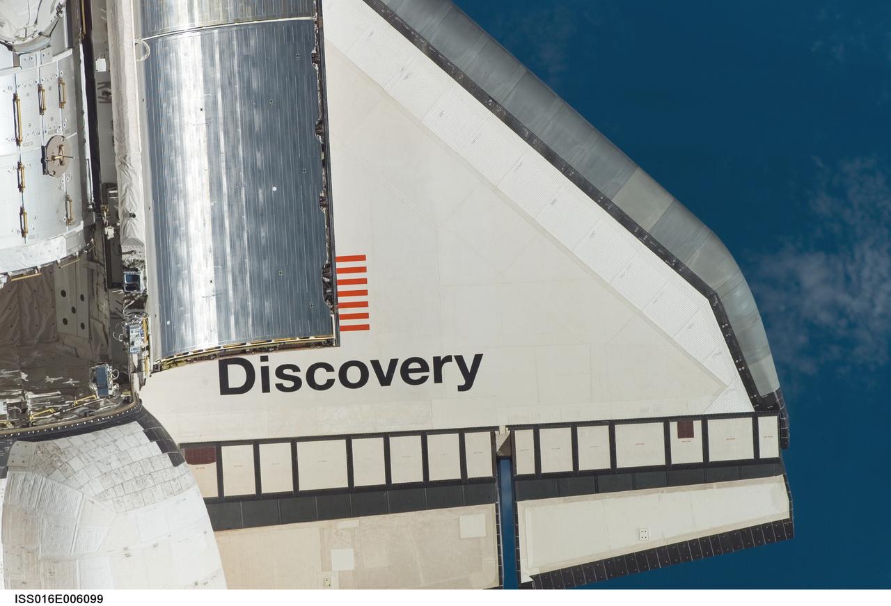
ISS016-E-006099 (25 Oct. 2007) --- Space Shuttle Discovery's starboard wing section is featured in this close-up image photographed by an Expedition 16 crewmember during a backflip maneuver performed by the approaching visitors (STS-120) to the International Space Station. Also visible are partial views of the orbital maneuvering system (OMS) pods and a portion of the Harmony node and payload bay door panels.
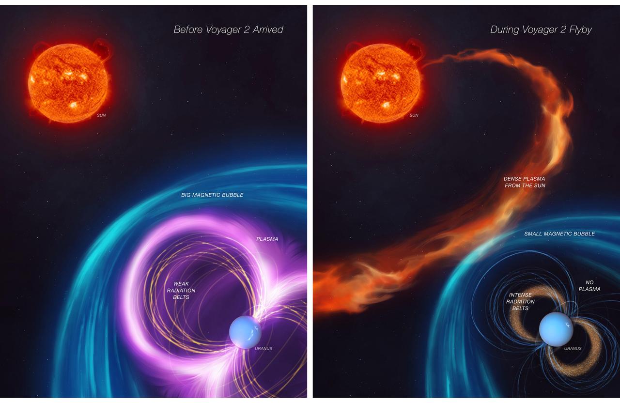
When NASA's Voyager 2 spacecraft flew by Uranus in 1986, it provided scientists' first – and, so far, only – close glimpse of this outer planet. Scientists were confronted by a mystery: The energized particles around the planet defied their understanding of how magnetic fields work to trap particle radiation. The first panel of this artist's concept depicts how Uranus's magnetosphere (its protective bubble) was behaving before Voyager 2's flyby. The second panel shows that an unusual kind of solar weather was happening at the same time as the spacecraft's flyby, giving scientists a skewed view of Uranus's magnetosphere. The work, led by a scientist at NASA's Jet Propulsion Laboratory and described in a paper published in Nature Astronomy in November 2024, contributes to scientists' understanding of this enigmatic planet. It also opens the door to the possibility that Uranus' five major moons may be active. https://photojournal.jpl.nasa.gov/catalog/PIA26069
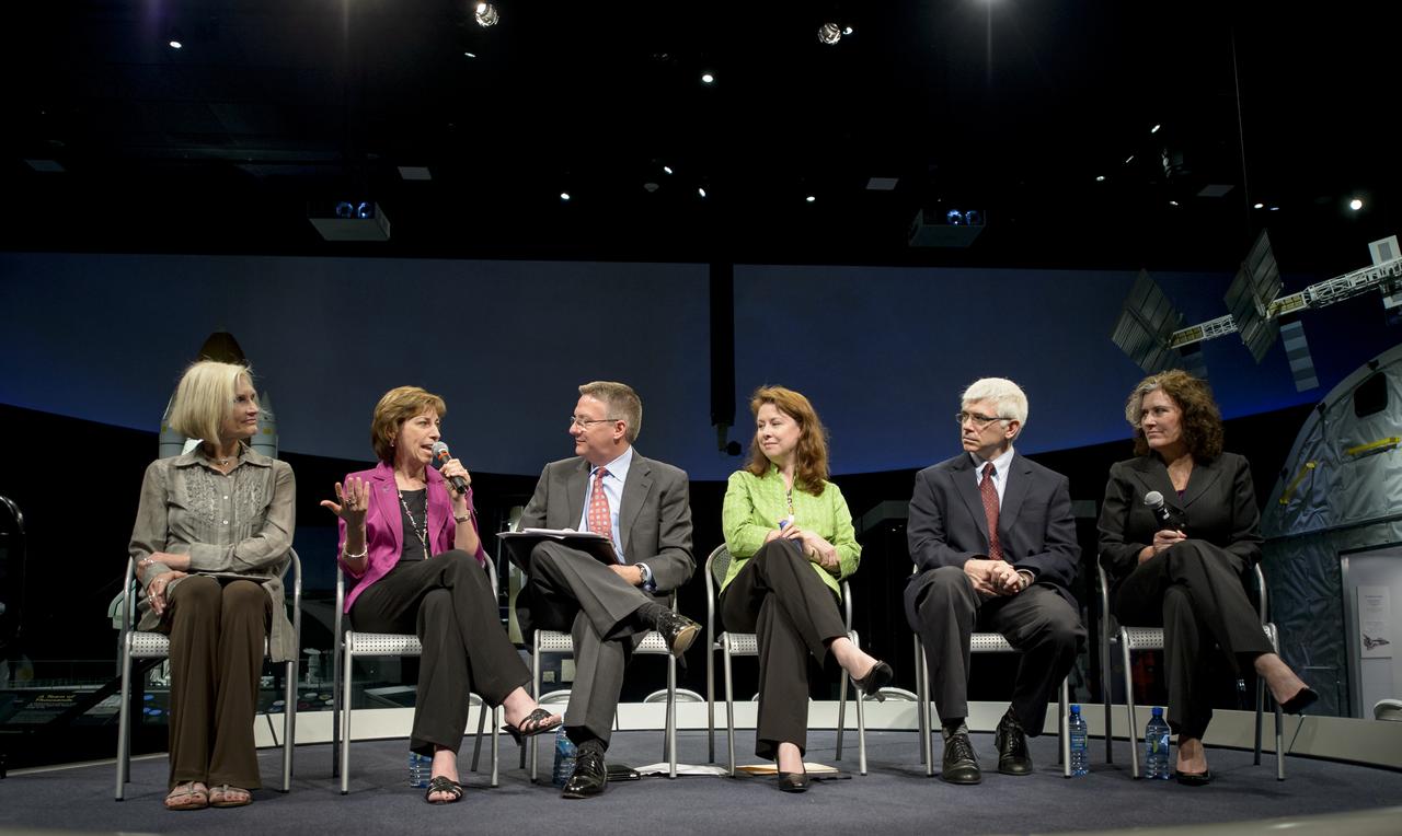
Panel discussion participants, from left, Linda Billings, research professor, Media and Public Affairs, The George Washington University, Ellen Ochoa, director, NASA Johnson Space Center, Tom Costello, NBC News and moderator for the event, Margaret Weitekamp, space history curator, National Air and Space Museum, Dan Vergano, science writer for USA Today, and Rene McCormick, director of standards and quality, National Math and Science Initiative, are seen during a program titled "Sally Ride: How Her Historic Space Mission Opened Doors for Women in Science" held on Friday, May 17, 2013 at the National Air and Space Museum in Washington. Photo Credit: (NASA/Bill Ingalls)
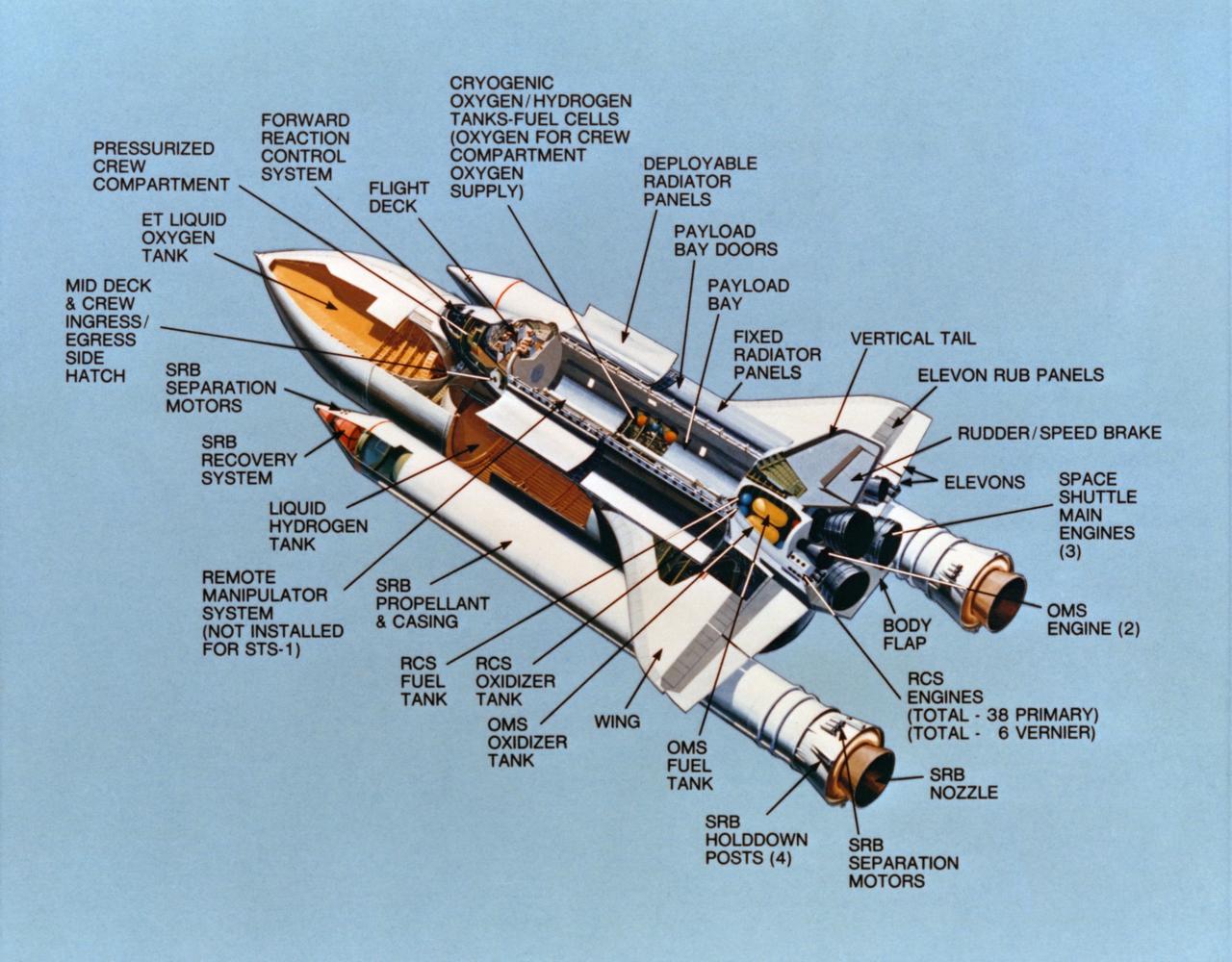
S81-30630 (February 1981) --- This "cutaway" artist's concept exercises some artistic license to reveal systems of the major components of a space shuttle vehicle. With its payload bay doors open here, the shuttle's cryogenic supply station (note cutaway) and the deployable radiator panels (visible) can be seen. In reality, the cargo bay panels would never be open while the orbiter is attached to the solid rocket boosters (SRB) and external fuel tank (ET). The thick-bodied, delta-winged aerospace craft is 37 meters long, has a span of 24 meters (120 feet by 80 feet), and weighs about 75,000 kilograms empty (165,000 lbs). Its payload bay, 18.3 meters long and 4.6 meters in diameter (60 feet by 15 feet) can deliver single or conglomerate payloads of up to 370 kilometers altitude or smaller loads up to 1110 kilometers (230 miles to 690 miles). It can bring payloads of 14,515 kilograms (32,000 lbs) back to Earth and it can carry out a variety of missions lasting seven to 30 days. Photo credit: NASA
The east side of the Vehicle Assembly Building (VAB) at Kennedy Space Center shows missing panels around the leaves of the upper door, the effect of the high winds from Hurricane Floyd as it passed along the East Coast of Florida, Sept. 14-15. At a weather tower located between Shuttle Launch Pad 39A and Launch Complex 41, the highest winds recorded during the superstorm were 91 mph from the NNW at 4:50 a.m. on Wednesday, Sept. 15. The maximum sustained winds were recorded at 66 mph. The highest amount of rain recorded at KSC was 2.82 inches as the eye of Hurricane Floyd passed 121 miles east of Cape Canaveral at 4 a.m. Wednesday. A preliminary review of conditions at the Kennedy Space Center was positive after the worst of Hurricane Floyd passed. There appeared to be no major damage to NASA assets, including the launch pads, the four Space Shuttle Orbiters, and flight hardware
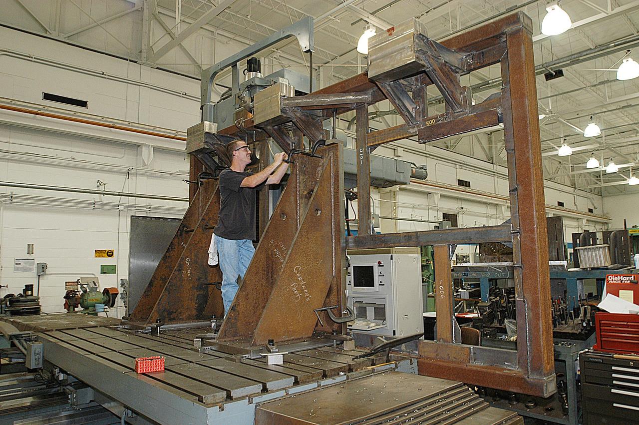
KENNEDY SPACE CENTER, FLA. -- United Space Alliance technician Matt Boonstra works on a main landing gear door mounting fixture in the Launch Equipment Shop. The fixture is being used to support the Columbia mishap investigation. A simulated orbiter wing and several test panels, along with sections of Space Shuttle orbiter Enterprise (OV-101), will be transferred to the Southwest Research Institute for testing after Thermal Protection System (TPS) tile installation on them is complete. The testing has been requested by the Columbia Accident Investigation Board. For this initiative, sections of Enterprise were borrowed from the Smithsonian Institution's Air and Space Museum where the orbiter is being stored at the Washington Dulles International Airport. Enterprise was the first orbiter built in the Shuttle fleet and was used to conduct the Approach and Landing Test Program before the first powered Shuttle flight.
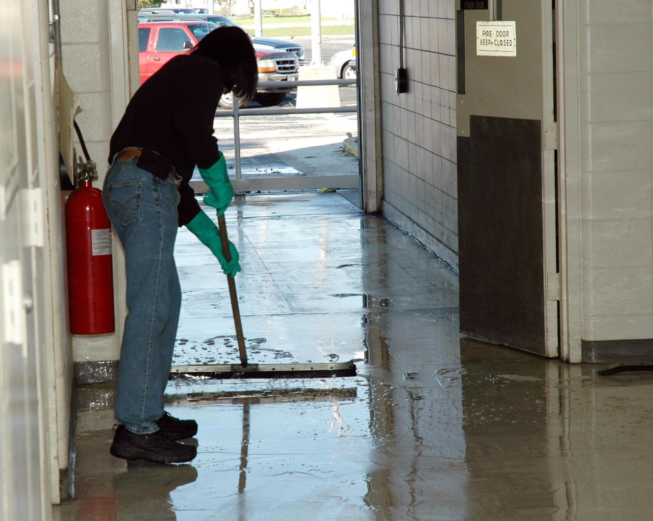
KENNEDY SPACE CENTER, FLA. - A worker at the NASA Kennedy Space Center sweeps water out the door of a building following the wrath of hurricane Wilma as it crossed the state Oct. 24. Kennedy’s facilities sustained minor structural damage, primarily to roofs or from water intrusion. The Vehicle Assembly Building lost some panels on the east and west sides. Some facilities lost power. A total of 13.6 inches of rain was recorded at the Shuttle Landing Facility. The highest wind gust recorded was 94 mph from the north-northwest at Launch Pad 39B, while the maximum sustained wind was 76 mph from the north-northwest at the top of the 492-foot weather tower located north of the Vehicle Assembly Building.
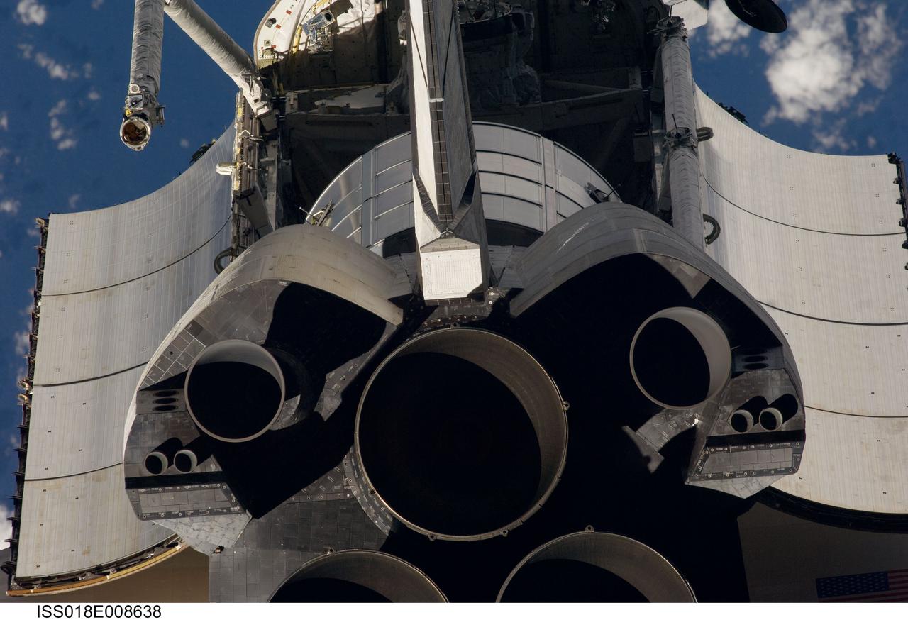
ISS018-E-008638 (16 Nov. 2008) --- A close-up view of Space Shuttle Endeavour's tail section was provided by Expedition 18 crewmembers on the International Space Station. The image provides partial views of the shuttle's main engines, orbital maneuvering system (OMS) pods, vertical stabilizer, the payload bay door panels and the Leonard Multi-Purpose Logistics Module located in the cargo bay. Before docking with the station, astronaut Chris Ferguson, STS-126 commander, flew the shuttle through a roll pitch maneuver or basically a backflip to allow the space station crew a good view of Endeavour's heat shield. Using digital still cameras equipped with both 400 and 800 millimeter lenses, the ISS crewmembers took a number of photos of the shuttle's thermal protection system and sent them down to teams on the ground for analysis. A 400 millimeter lens was used for this image.
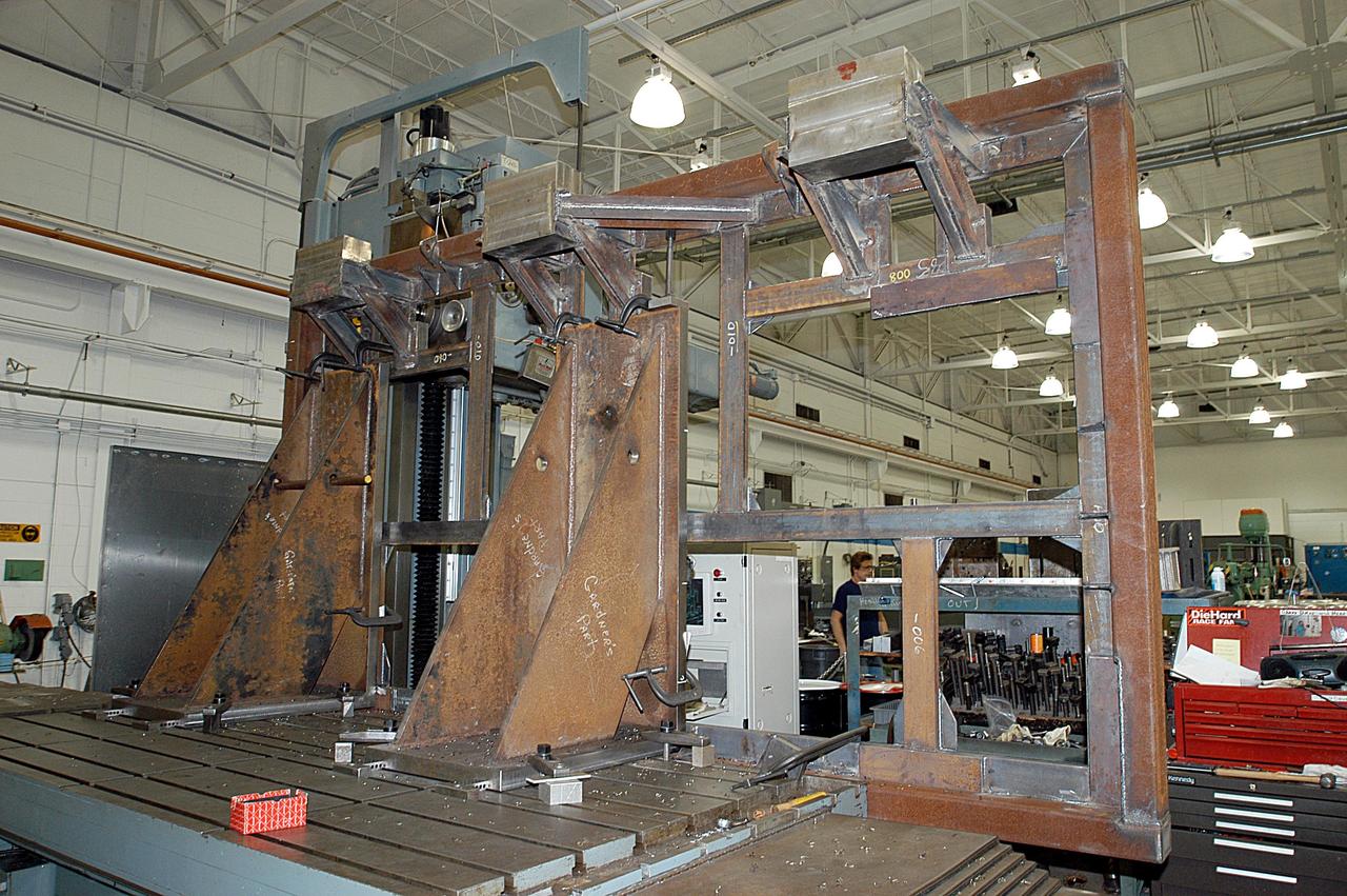
KENNEDY SPACE CENTER, FLA. -- A main landing gear door mounting fixture in the Launch Equipment Shop is being used to support the Columbia mishap investigation. A simulated orbiter wing and several test panels, along with sections of Space Shuttle orbiter Enterprise (OV-101), will be transferred to the Southwest Research Institute for testing after Thermal Protection System (TPS) tile installation is complete. The testing has been requested by the Columbia Accident Investigation Board. For this initiative, sections of Enterprise were borrowed from the Smithsonian Institution's Air and Space Museum where the orbiter is being stored at the Washington Dulles International Airport. Enterprise was the first orbiter built in the Shuttle fleet and was used to conduct the Approach and Landing Test Program before the first powered Shuttle flight.
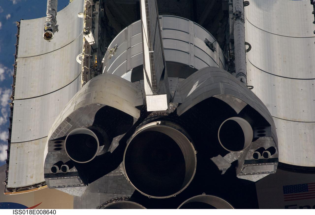
ISS018-E-008640 (16 Nov. 2008) --- A close-up view of Space Shuttle Endeavour's tail section was provided by Expedition 18 crewmembers on the International Space Station. The image provides partial views of the shuttle's main engines, orbital maneuvering system (OMS) pods, vertical stabilizer, the payload bay door panels and the Leonard Multi-Purpose Logistics Module located in the cargo bay. Before docking with the station, astronaut Chris Ferguson, STS-126 commander, flew the shuttle through a roll pitch maneuver or basically a backflip to allow the space station crew a good view of Endeavour's heat shield. Using digital still cameras equipped with both 400 and 800 millimeter lenses, the ISS crewmembers took a number of photos of the shuttle's thermal protection system and sent them down to teams on the ground for analysis. A 400 millimeter lens was used for this image.
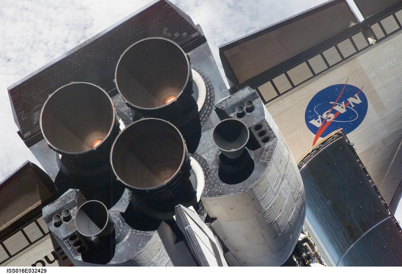
ISS016-E-032429 (12 March 2008) --- A close-up view of Space Shuttle Endeavour's tail section was provided by Expedition 16 crewmembers on the International Space Station (ISS). The image provides partial views of the shuttle's main engines, orbital maneuvering system (OMS) pods, a portion of the payload bay door panels and the shuttle's wings. Before docking with the station, astronaut Dominic Gorie, STS-123 commander, flew the shuttle through a roll pitch maneuver or basically a backflip to allow the space station crew a good view of Endeavour's heat shield. Using digital still cameras equipped with both 400 and 800 millimeter lenses, the ISS crewmembers took a number of photos of the shuttle's thermal protection system and sent them down to teams on the ground for analysis. A 400 millimeter lens was used for this image.
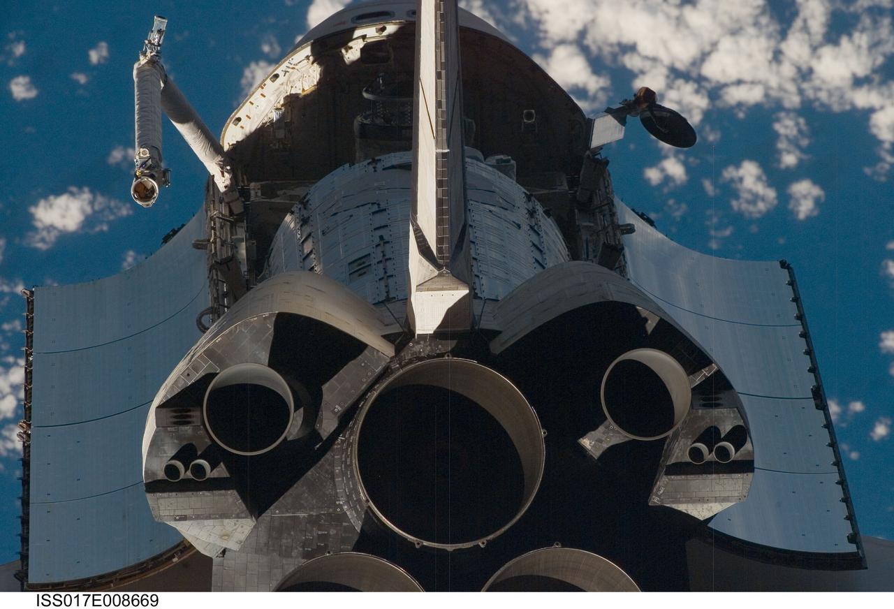
ISS017-E-008669 (2 June 2008) --- A close-up view of Space Shuttle Discovery's tail section was provided by Expedition 17 crewmembers on the International Space Station (ISS). The image provides partial views of the shuttle's main engines, orbital maneuvering system (OMS) pods, vertical stabilizer, the payload bay door panels and the second component of the Japan Aerospace Exploration Agency's Kibo laboratory, the Japanese Pressurized Module (JPM) located in the cargo bay. Before docking with the station, astronaut Mark Kelly, STS-124 commander, flew the shuttle through a roll pitch maneuver or basically a backflip to allow the space station crew a good view of Discovery's heat shield. Using digital still cameras equipped with both 400 and 800 millimeter lenses, the ISS crewmembers took a number of photos of the shuttle's thermal protection system and sent them down to teams on the ground for analysis. A 400 millimeter lens was used for this image.
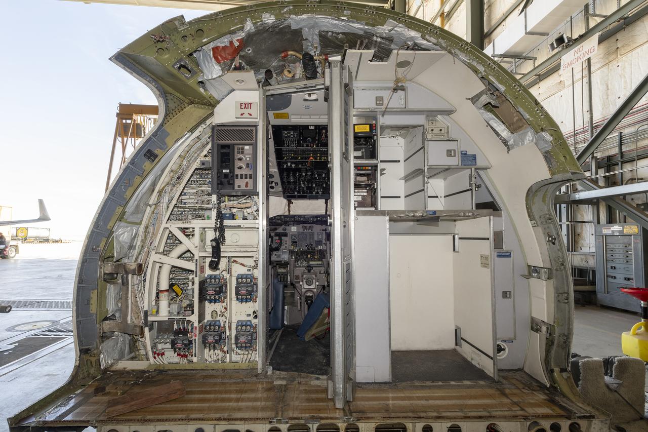
The cockpit of an old MD-90 aircraft arrived at NASA’s Armstrong Flight Research Center in Edwards, California, in March 2024. Parts will be used to build a simulator for NASA’s X-66, the demonstration aircraft for the Sustainable Flight Demonstrator project.
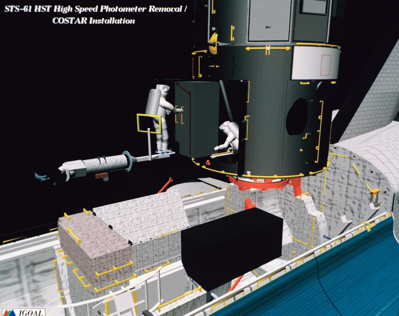
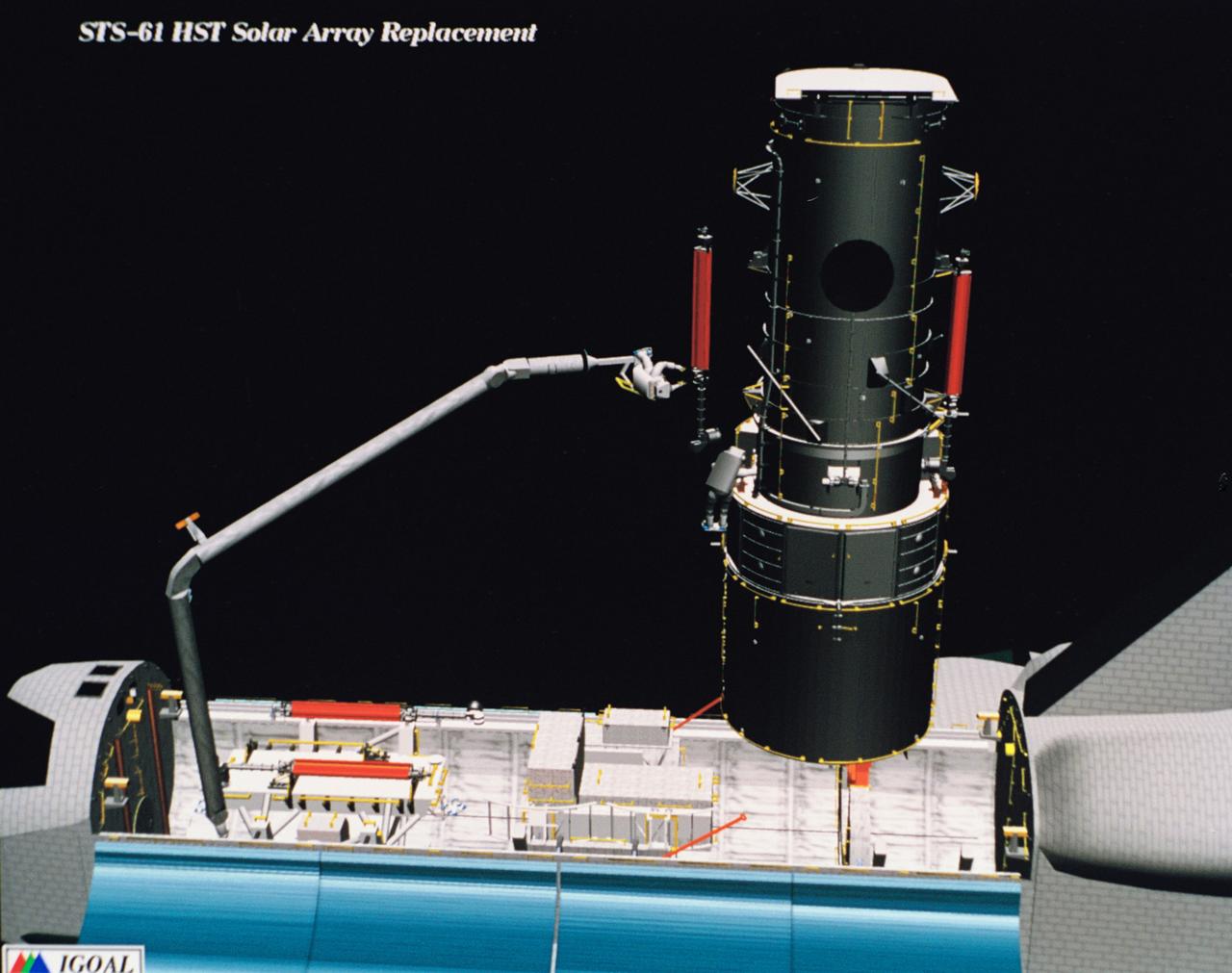
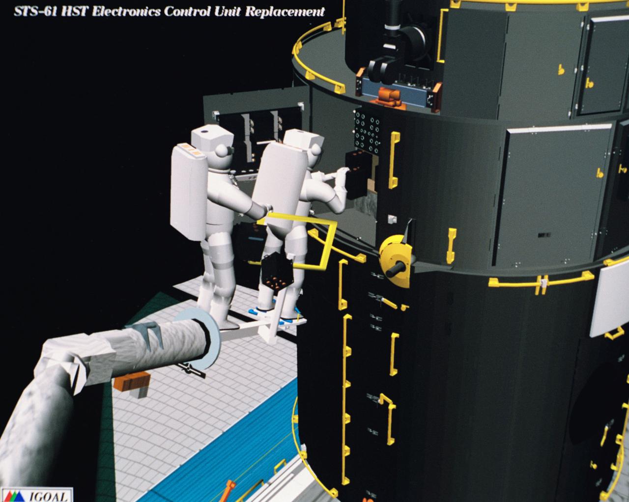
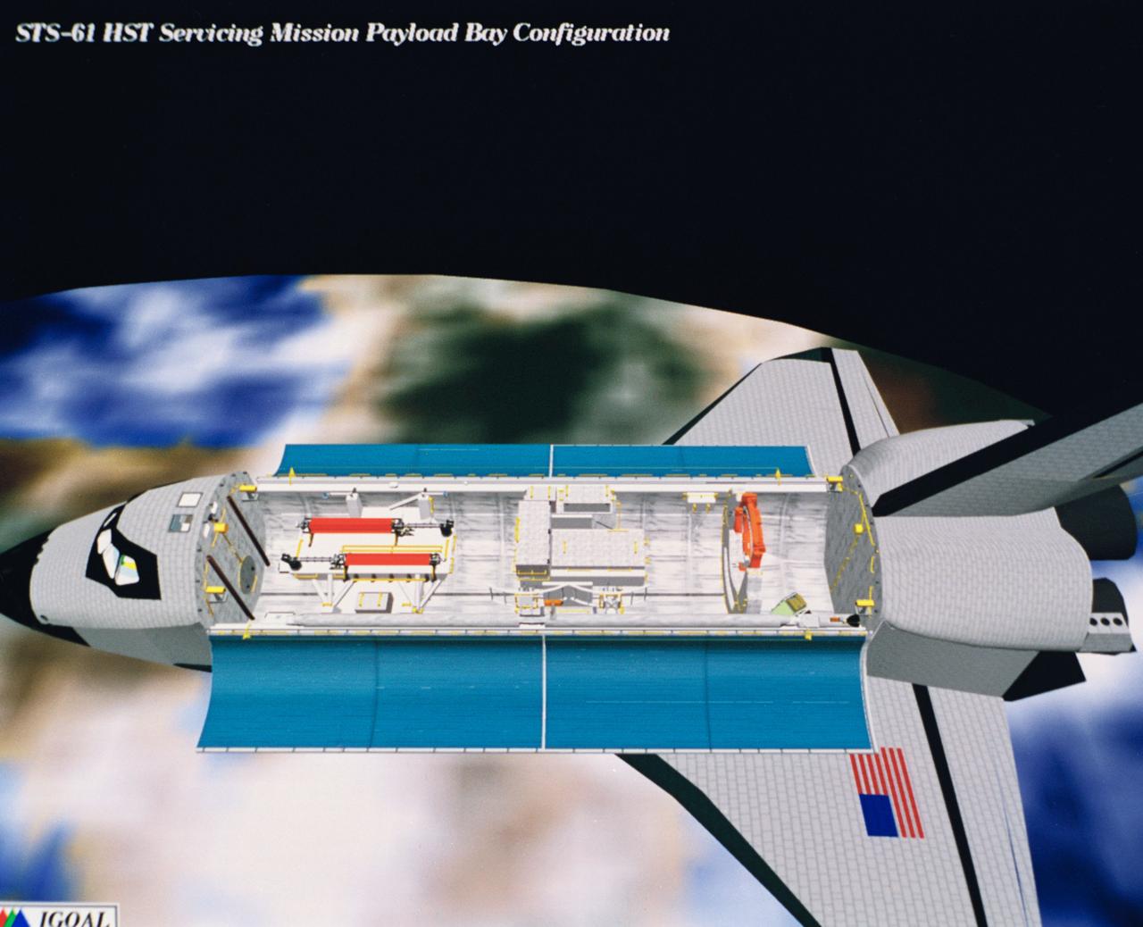
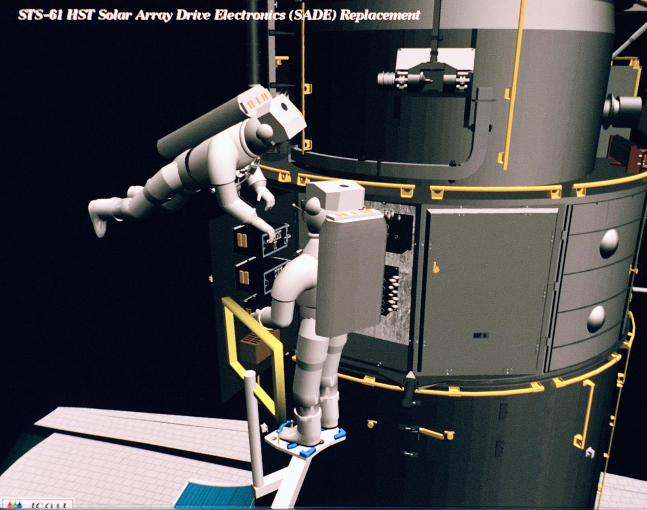
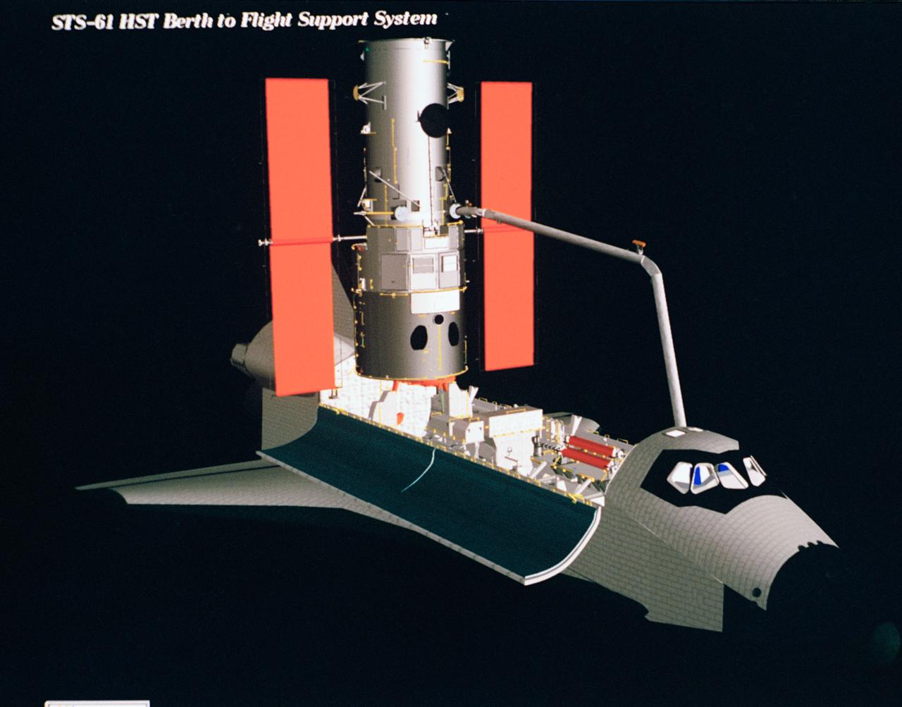
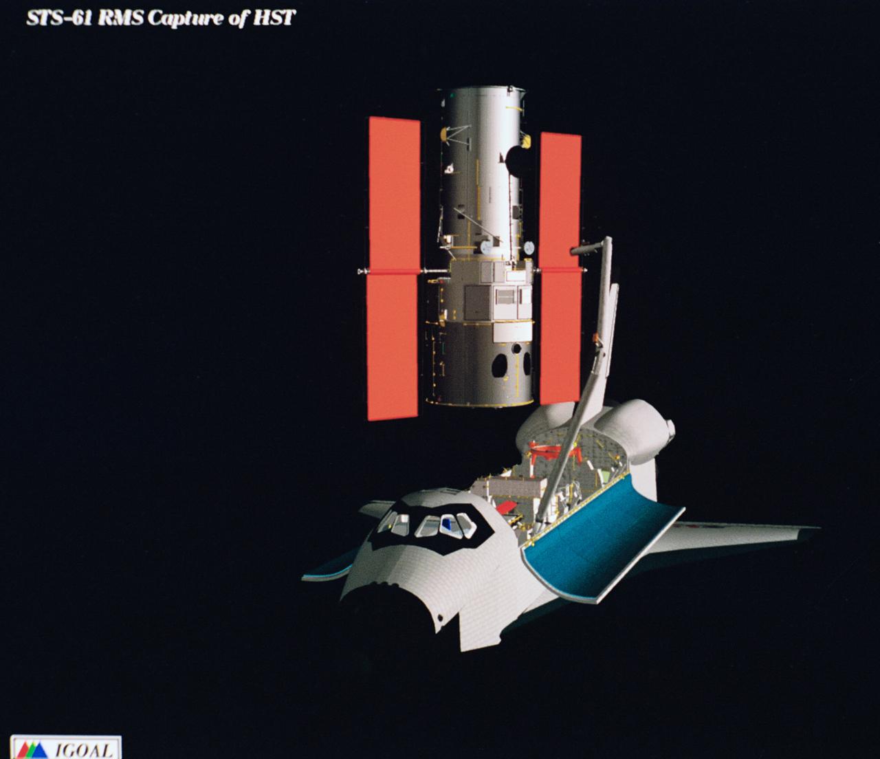
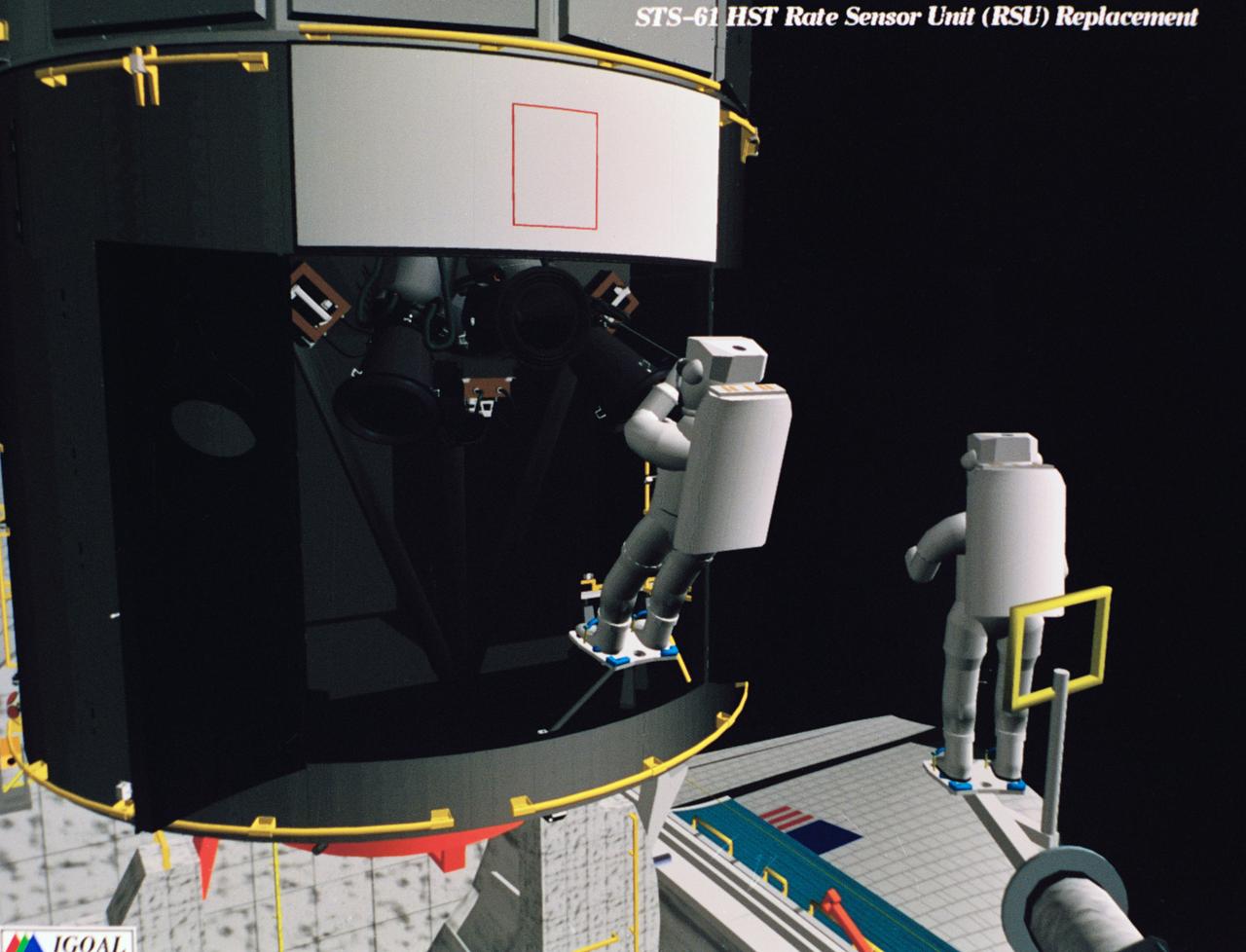
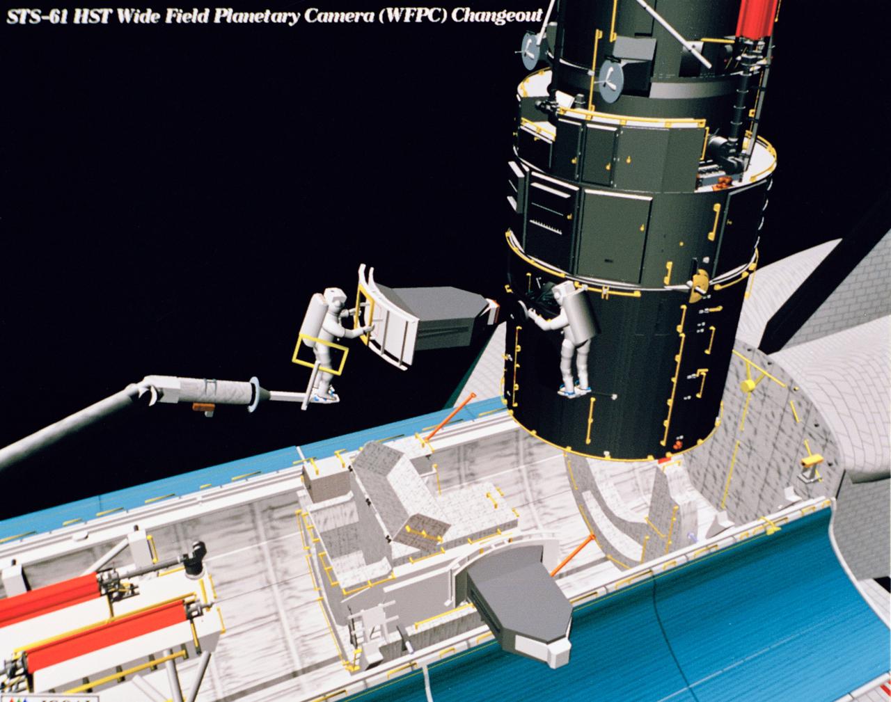
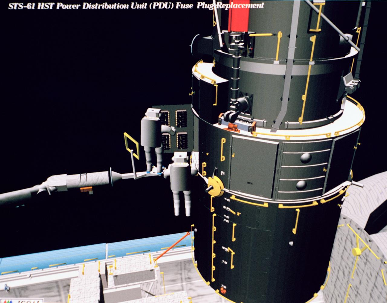
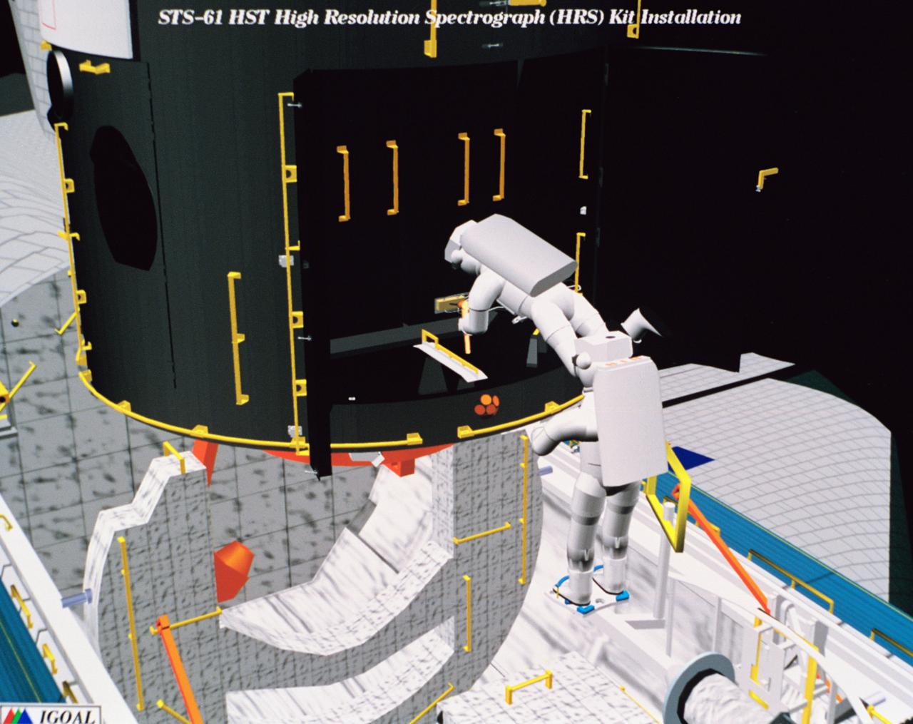
Computer generated scenes depicting the Hubble Space Telescope capture and a sequence of planned events on the planned extravehicular activity (EVA). Scenes include the Remote Manipulator System (RMS) arm assisting two astronauts changing out the Wide Field/Planetary Camera (WF/PC) (48699); RMS arm assisting in the temporary mating of the orbiting telescope to the flight support system in Endeavour's cargo bay (48700); Endeavour's RMS arm assisting in the "capture" of the orbiting telescope (48701); Two astronauts changing out the telescope's coprocessor (48702); RMS arm assistign two astronauts replacing one of the telescope's electronic control units (48703); RMS assisting two astronauts replacing the fuse plugs on the telescope's Power Distribution Unit (PDU) (48704); The telescope's High Resolution Spectrograph (HRS) kit is depicted in this scene (48705); Two astronauts during the removal of the high speed photometer and the installation of the COSTAR instrument (48706); Two astronauts, standing on the RMS, during installation of one of the Magnetic Sensing System (MSS) (48707); High angle view of the orbiting Space Shuttle Endeavour with its cargo bay doors open, revealing the bay's pre-capture configuration. Seen are, from the left, the Solar Array Carrier, the ORU Carrier and the flight support system (48708); Two astronauts performing the replacement of HST's Rate Sensor Units (RSU) (48709); The RMS arm assisting two astronauts with the replacement of the telescope's solar array panels (48710); Two astronauts replacing the telescope's Solar Array Drive Electronics (SADE) (48711).
Computer generated scenes depicting the Hubble Space Telescope capture and a sequence of planned events on the planned extravehicular activity (EVA). Scenes include the Remote Manipulator System (RMS) arm assisting two astronauts changing out the Wide Field/Planetary Camera (WF/PC) (48699); RMS arm assisting in the temporary mating of the orbiting telescope to the flight support system in Endeavour's cargo bay (48700); Endeavour's RMS arm assisting in the "capture" of the orbiting telescope (48701); Two astronauts changing out the telescope's coprocessor (48702); RMS arm assistign two astronauts replacing one of the telescope's electronic control units (48703); RMS assisting two astronauts replacing the fuse plugs on the telescope's Power Distribution Unit (PDU) (48704); The telescope's High Resolution Spectrograph (HRS) kit is depicted in this scene (48705); Two astronauts during the removal of the high speed photometer and the installation of the COSTAR instrument (48706); Two astronauts, standing on the RMS, during installation of one of the Magnetic Sensing System (MSS) (48707); High angle view of the orbiting Space Shuttle Endeavour with its cargo bay doors open, revealing the bay's pre-capture configuration. Seen are, from the left, the Solar Array Carrier, the ORU Carrier and the flight support system (48708); Two astronauts performing the replacement of HST's Rate Sensor Units (RSU) (48709); The RMS arm assisting two astronauts with the replacement of the telescope's solar array panels (48710); Two astronauts replacing the telescope's Solar Array Drive Electronics (SADE) (48711).
Computer generated scenes depicting the Hubble Space Telescope capture and a sequence of planned events on the planned extravehicular activity (EVA). Scenes include the Remote Manipulator System (RMS) arm assisting two astronauts changing out the Wide Field/Planetary Camera (WF/PC) (48699); RMS arm assisting in the temporary mating of the orbiting telescope to the flight support system in Endeavour's cargo bay (48700); Endeavour's RMS arm assisting in the "capture" of the orbiting telescope (48701); Two astronauts changing out the telescope's coprocessor (48702); RMS arm assistign two astronauts replacing one of the telescope's electronic control units (48703); RMS assisting two astronauts replacing the fuse plugs on the telescope's Power Distribution Unit (PDU) (48704); The telescope's High Resolution Spectrograph (HRS) kit is depicted in this scene (48705); Two astronauts during the removal of the high speed photometer and the installation of the COSTAR instrument (48706); Two astronauts, standing on the RMS, during installation of one of the Magnetic Sensing System (MSS) (48707); High angle view of the orbiting Space Shuttle Endeavour with its cargo bay doors open, revealing the bay's pre-capture configuration. Seen are, from the left, the Solar Array Carrier, the ORU Carrier and the flight support system (48708); Two astronauts performing the replacement of HST's Rate Sensor Units (RSU) (48709); The RMS arm assisting two astronauts with the replacement of the telescope's solar array panels (48710); Two astronauts replacing the telescope's Solar Array Drive Electronics (SADE) (48711).
Computer generated scenes depicting the Hubble Space Telescope capture and a sequence of planned events on the planned extravehicular activity (EVA). Scenes include the Remote Manipulator System (RMS) arm assisting two astronauts changing out the Wide Field/Planetary Camera (WF/PC) (48699); RMS arm assisting in the temporary mating of the orbiting telescope to the flight support system in Endeavour's cargo bay (48700); Endeavour's RMS arm assisting in the "capture" of the orbiting telescope (48701); Two astronauts changing out the telescope's coprocessor (48702); RMS arm assistign two astronauts replacing one of the telescope's electronic control units (48703); RMS assisting two astronauts replacing the fuse plugs on the telescope's Power Distribution Unit (PDU) (48704); The telescope's High Resolution Spectrograph (HRS) kit is depicted in this scene (48705); Two astronauts during the removal of the high speed photometer and the installation of the COSTAR instrument (48706); Two astronauts, standing on the RMS, during installation of one of the Magnetic Sensing System (MSS) (48707); High angle view of the orbiting Space Shuttle Endeavour with its cargo bay doors open, revealing the bay's pre-capture configuration. Seen are, from the left, the Solar Array Carrier, the ORU Carrier and the flight support system (48708); Two astronauts performing the replacement of HST's Rate Sensor Units (RSU) (48709); The RMS arm assisting two astronauts with the replacement of the telescope's solar array panels (48710); Two astronauts replacing the telescope's Solar Array Drive Electronics (SADE) (48711).

Computer generated scenes depicting the Hubble Space Telescope capture and a sequence of planned events on the planned extravehicular activity (EVA). Scenes include the Remote Manipulator System (RMS) arm assisting two astronauts changing out the Wide Field/Planetary Camera (WF/PC) (48699); RMS arm assisting in the temporary mating of the orbiting telescope to the flight support system in Endeavour's cargo bay (48700); Endeavour's RMS arm assisting in the "capture" of the orbiting telescope (48701); Two astronauts changing out the telescope's coprocessor (48702); RMS arm assistign two astronauts replacing one of the telescope's electronic control units (48703); RMS assisting two astronauts replacing the fuse plugs on the telescope's Power Distribution Unit (PDU) (48704); The telescope's High Resolution Spectrograph (HRS) kit is depicted in this scene (48705); Two astronauts during the removal of the high speed photometer and the installation of the COSTAR instrument (48706); Two astronauts, standing on the RMS, during installation of one of the Magnetic Sensing System (MSS) (48707); High angle view of the orbiting Space Shuttle Endeavour with its cargo bay doors open, revealing the bay's pre-capture configuration. Seen are, from the left, the Solar Array Carrier, the ORU Carrier and the flight support system (48708); Two astronauts performing the replacement of HST's Rate Sensor Units (RSU) (48709); The RMS arm assisting two astronauts with the replacement of the telescope's solar array panels (48710); Two astronauts replacing the telescope's Solar Array Drive Electronics (SADE) (48711).
Computer generated scenes depicting the Hubble Space Telescope capture and a sequence of planned events on the planned extravehicular activity (EVA). Scenes include the Remote Manipulator System (RMS) arm assisting two astronauts changing out the Wide Field/Planetary Camera (WF/PC) (48699); RMS arm assisting in the temporary mating of the orbiting telescope to the flight support system in Endeavour's cargo bay (48700); Endeavour's RMS arm assisting in the "capture" of the orbiting telescope (48701); Two astronauts changing out the telescope's coprocessor (48702); RMS arm assistign two astronauts replacing one of the telescope's electronic control units (48703); RMS assisting two astronauts replacing the fuse plugs on the telescope's Power Distribution Unit (PDU) (48704); The telescope's High Resolution Spectrograph (HRS) kit is depicted in this scene (48705); Two astronauts during the removal of the high speed photometer and the installation of the COSTAR instrument (48706); Two astronauts, standing on the RMS, during installation of one of the Magnetic Sensing System (MSS) (48707); High angle view of the orbiting Space Shuttle Endeavour with its cargo bay doors open, revealing the bay's pre-capture configuration. Seen are, from the left, the Solar Array Carrier, the ORU Carrier and the flight support system (48708); Two astronauts performing the replacement of HST's Rate Sensor Units (RSU) (48709); The RMS arm assisting two astronauts with the replacement of the telescope's solar array panels (48710); Two astronauts replacing the telescope's Solar Array Drive Electronics (SADE) (48711).
Computer generated scenes depicting the Hubble Space Telescope capture and a sequence of planned events on the planned extravehicular activity (EVA). Scenes include the Remote Manipulator System (RMS) arm assisting two astronauts changing out the Wide Field/Planetary Camera (WF/PC) (48699); RMS arm assisting in the temporary mating of the orbiting telescope to the flight support system in Endeavour's cargo bay (48700); Endeavour's RMS arm assisting in the "capture" of the orbiting telescope (48701); Two astronauts changing out the telescope's coprocessor (48702); RMS arm assistign two astronauts replacing one of the telescope's electronic control units (48703); RMS assisting two astronauts replacing the fuse plugs on the telescope's Power Distribution Unit (PDU) (48704); The telescope's High Resolution Spectrograph (HRS) kit is depicted in this scene (48705); Two astronauts during the removal of the high speed photometer and the installation of the COSTAR instrument (48706); Two astronauts, standing on the RMS, during installation of one of the Magnetic Sensing System (MSS) (48707); High angle view of the orbiting Space Shuttle Endeavour with its cargo bay doors open, revealing the bay's pre-capture configuration. Seen are, from the left, the Solar Array Carrier, the ORU Carrier and the flight support system (48708); Two astronauts performing the replacement of HST's Rate Sensor Units (RSU) (48709); The RMS arm assisting two astronauts with the replacement of the telescope's solar array panels (48710); Two astronauts replacing the telescope's Solar Array Drive Electronics (SADE) (48711).
Computer generated scenes depicting the Hubble Space Telescope capture and a sequence of planned events on the planned extravehicular activity (EVA). Scenes include the Remote Manipulator System (RMS) arm assisting two astronauts changing out the Wide Field/Planetary Camera (WF/PC) (48699); RMS arm assisting in the temporary mating of the orbiting telescope to the flight support system in Endeavour's cargo bay (48700); Endeavour's RMS arm assisting in the "capture" of the orbiting telescope (48701); Two astronauts changing out the telescope's coprocessor (48702); RMS arm assistign two astronauts replacing one of the telescope's electronic control units (48703); RMS assisting two astronauts replacing the fuse plugs on the telescope's Power Distribution Unit (PDU) (48704); The telescope's High Resolution Spectrograph (HRS) kit is depicted in this scene (48705); Two astronauts during the removal of the high speed photometer and the installation of the COSTAR instrument (48706); Two astronauts, standing on the RMS, during installation of one of the Magnetic Sensing System (MSS) (48707); High angle view of the orbiting Space Shuttle Endeavour with its cargo bay doors open, revealing the bay's pre-capture configuration. Seen are, from the left, the Solar Array Carrier, the ORU Carrier and the flight support system (48708); Two astronauts performing the replacement of HST's Rate Sensor Units (RSU) (48709); The RMS arm assisting two astronauts with the replacement of the telescope's solar array panels (48710); Two astronauts replacing the telescope's Solar Array Drive Electronics (SADE) (48711).
Computer generated scenes depicting the Hubble Space Telescope capture and a sequence of planned events on the planned extravehicular activity (EVA). Scenes include the Remote Manipulator System (RMS) arm assisting two astronauts changing out the Wide Field/Planetary Camera (WF/PC) (48699); RMS arm assisting in the temporary mating of the orbiting telescope to the flight support system in Endeavour's cargo bay (48700); Endeavour's RMS arm assisting in the "capture" of the orbiting telescope (48701); Two astronauts changing out the telescope's coprocessor (48702); RMS arm assistign two astronauts replacing one of the telescope's electronic control units (48703); RMS assisting two astronauts replacing the fuse plugs on the telescope's Power Distribution Unit (PDU) (48704); The telescope's High Resolution Spectrograph (HRS) kit is depicted in this scene (48705); Two astronauts during the removal of the high speed photometer and the installation of the COSTAR instrument (48706); Two astronauts, standing on the RMS, during installation of one of the Magnetic Sensing System (MSS) (48707); High angle view of the orbiting Space Shuttle Endeavour with its cargo bay doors open, revealing the bay's pre-capture configuration. Seen are, from the left, the Solar Array Carrier, the ORU Carrier and the flight support system (48708); Two astronauts performing the replacement of HST's Rate Sensor Units (RSU) (48709); The RMS arm assisting two astronauts with the replacement of the telescope's solar array panels (48710); Two astronauts replacing the telescope's Solar Array Drive Electronics (SADE) (48711).
Computer generated scenes depicting the Hubble Space Telescope capture and a sequence of planned events on the planned extravehicular activity (EVA). Scenes include the Remote Manipulator System (RMS) arm assisting two astronauts changing out the Wide Field/Planetary Camera (WF/PC) (48699); RMS arm assisting in the temporary mating of the orbiting telescope to the flight support system in Endeavour's cargo bay (48700); Endeavour's RMS arm assisting in the "capture" of the orbiting telescope (48701); Two astronauts changing out the telescope's coprocessor (48702); RMS arm assistign two astronauts replacing one of the telescope's electronic control units (48703); RMS assisting two astronauts replacing the fuse plugs on the telescope's Power Distribution Unit (PDU) (48704); The telescope's High Resolution Spectrograph (HRS) kit is depicted in this scene (48705); Two astronauts during the removal of the high speed photometer and the installation of the COSTAR instrument (48706); Two astronauts, standing on the RMS, during installation of one of the Magnetic Sensing System (MSS) (48707); High angle view of the orbiting Space Shuttle Endeavour with its cargo bay doors open, revealing the bay's pre-capture configuration. Seen are, from the left, the Solar Array Carrier, the ORU Carrier and the flight support system (48708); Two astronauts performing the replacement of HST's Rate Sensor Units (RSU) (48709); The RMS arm assisting two astronauts with the replacement of the telescope's solar array panels (48710); Two astronauts replacing the telescope's Solar Array Drive Electronics (SADE) (48711).
Computer generated scenes depicting the Hubble Space Telescope capture and a sequence of planned events on the planned extravehicular activity (EVA). Scenes include the Remote Manipulator System (RMS) arm assisting two astronauts changing out the Wide Field/Planetary Camera (WF/PC) (48699); RMS arm assisting in the temporary mating of the orbiting telescope to the flight support system in Endeavour's cargo bay (48700); Endeavour's RMS arm assisting in the "capture" of the orbiting telescope (48701); Two astronauts changing out the telescope's coprocessor (48702); RMS arm assistign two astronauts replacing one of the telescope's electronic control units (48703); RMS assisting two astronauts replacing the fuse plugs on the telescope's Power Distribution Unit (PDU) (48704); The telescope's High Resolution Spectrograph (HRS) kit is depicted in this scene (48705); Two astronauts during the removal of the high speed photometer and the installation of the COSTAR instrument (48706); Two astronauts, standing on the RMS, during installation of one of the Magnetic Sensing System (MSS) (48707); High angle view of the orbiting Space Shuttle Endeavour with its cargo bay doors open, revealing the bay's pre-capture configuration. Seen are, from the left, the Solar Array Carrier, the ORU Carrier and the flight support system (48708); Two astronauts performing the replacement of HST's Rate Sensor Units (RSU) (48709); The RMS arm assisting two astronauts with the replacement of the telescope's solar array panels (48710); Two astronauts replacing the telescope's Solar Array Drive Electronics (SADE) (48711).
Computer generated scenes depicting the Hubble Space Telescope capture and a sequence of planned events on the planned extravehicular activity (EVA). Scenes include the Remote Manipulator System (RMS) arm assisting two astronauts changing out the Wide Field/Planetary Camera (WF/PC) (48699); RMS arm assisting in the temporary mating of the orbiting telescope to the flight support system in Endeavour's cargo bay (48700); Endeavour's RMS arm assisting in the "capture" of the orbiting telescope (48701); Two astronauts changing out the telescope's coprocessor (48702); RMS arm assistign two astronauts replacing one of the telescope's electronic control units (48703); RMS assisting two astronauts replacing the fuse plugs on the telescope's Power Distribution Unit (PDU) (48704); The telescope's High Resolution Spectrograph (HRS) kit is depicted in this scene (48705); Two astronauts during the removal of the high speed photometer and the installation of the COSTAR instrument (48706); Two astronauts, standing on the RMS, during installation of one of the Magnetic Sensing System (MSS) (48707); High angle view of the orbiting Space Shuttle Endeavour with its cargo bay doors open, revealing the bay's pre-capture configuration. Seen are, from the left, the Solar Array Carrier, the ORU Carrier and the flight support system (48708); Two astronauts performing the replacement of HST's Rate Sensor Units (RSU) (48709); The RMS arm assisting two astronauts with the replacement of the telescope's solar array panels (48710); Two astronauts replacing the telescope's Solar Array Drive Electronics (SADE) (48711).
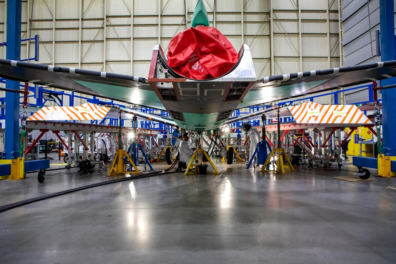
Technicians perform landing gear checkout testing at Lockheed Martin Skunk Works in Palmdale, California. These tests make sure that all the parts of X-59’s landing gear and doors are working in the correct order. The X-59 is the centerpiece of NASA’s Quesst mission, which could help enable commercial supersonic air travel over land.
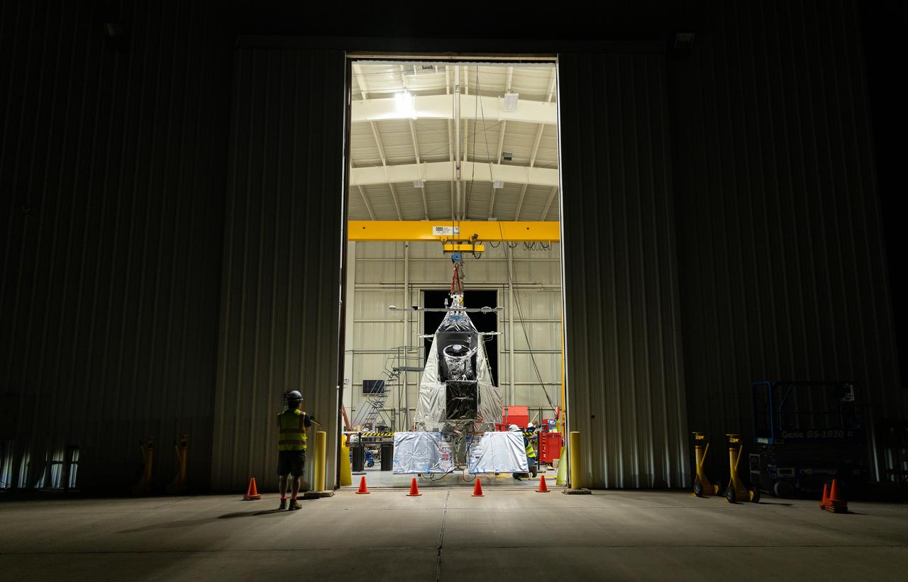
NASA Goddard astrophysicist Kyle Helson looks at EXCITE (EXoplanet Climate Infrared TElescope) as it dangles from the ceiling of a hangar at NASA’s Columbia Scientific Balloon Facility in Fort Sumner, New Mexico.
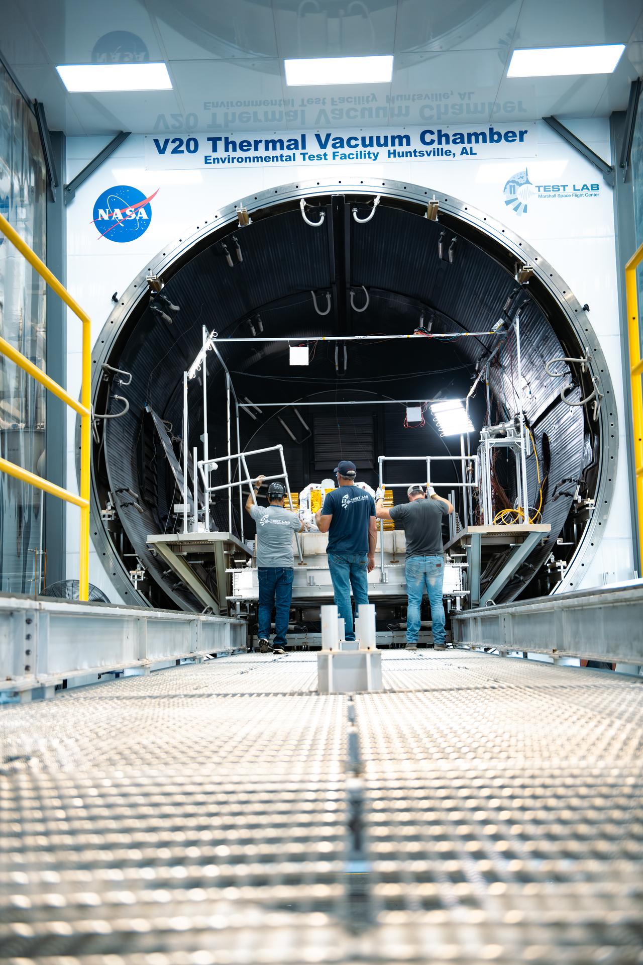
NASA Environmental Test Facility employees at the agency’s Marshall Space Flight Center in Huntsville, Alabama, work with members from the Starpath team to push the sliding platform into the thermal vacuum chamber, with the heavy rover and concrete slab in tow. The technology startup headquartered in Hawthorne, California, won second place overall at the agency’s Break the Ice Lunar Challenge’s live demonstration and finale in June 2024. This competition, one of NASA’s Centennial Challenges, tasked competitors to design, build, and demonstrate robotic technologies that could excavate and transport the icy, rocky dirt – otherwise known as regolith – found on the Moon. Starpath’s visit to NASA Marshall was part of their prize opportunity to test their upgraded lunar regolith excavation and transportation rover in the center’s 20-foot thermal vacuum chamber. For more information, contact NASA Marshall’s Office of Communications at 256-544-0034.
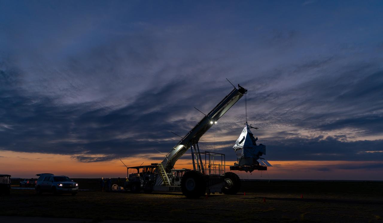
NASA Goddard astrophysicist Kyle Helson looks at EXCITE (EXoplanet Climate Infrared TElescope) as it dangles from the ceiling of a hangar at NASA’s Columbia Scientific Balloon Facility in Fort Sumner, New Mexico.
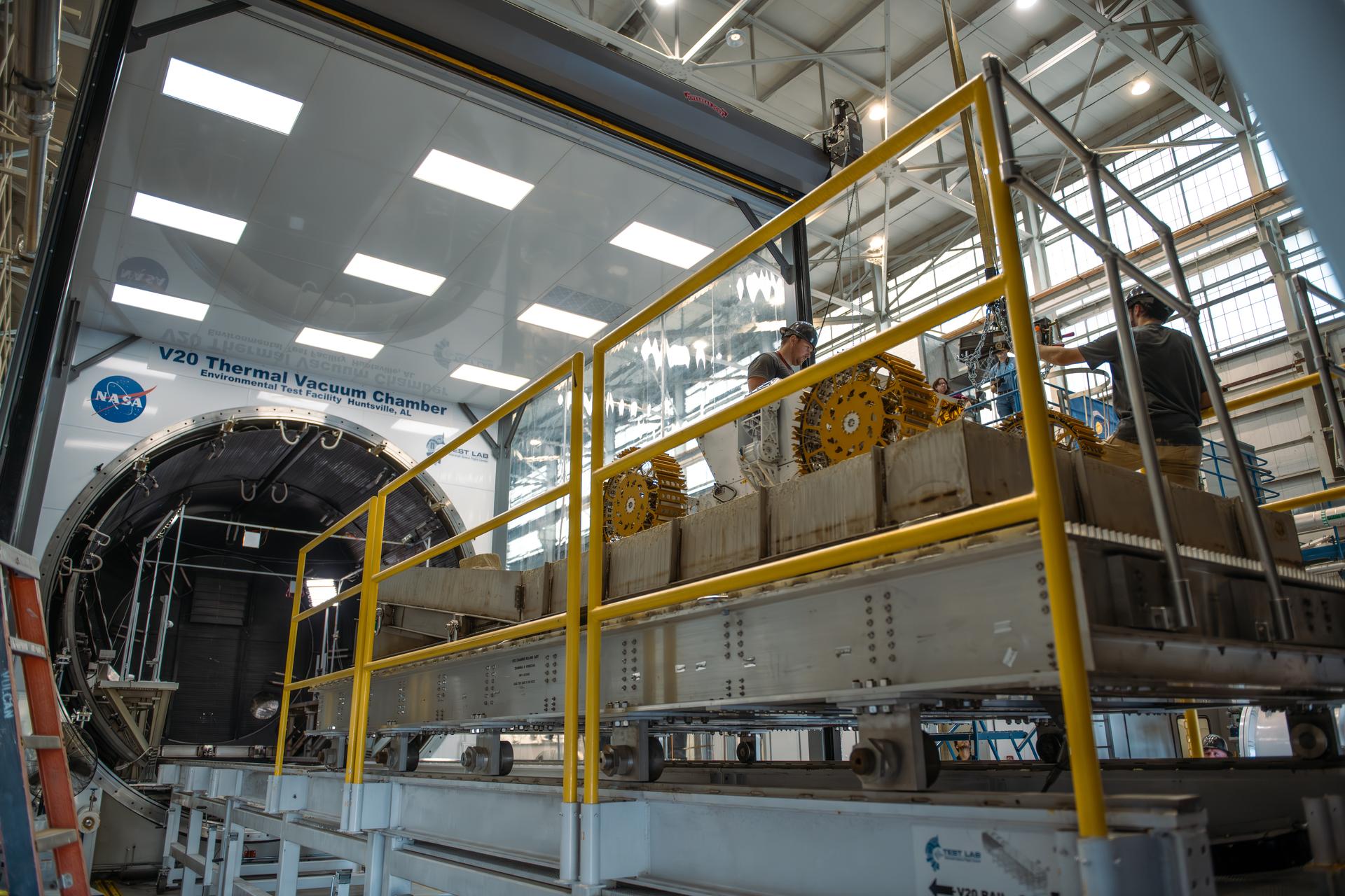
Starpath’s rover freely rests on a concrete slab at the end of a platform at NASA’s Marshall Space Flight Center in Huntsville, Alabama. The large metal structure will slide into the chamber, bringing the rover and concrete slab with it. The technology startup headquartered in Hawthorne, California, won second place overall at the agency’s Break the Ice Lunar Challenge’s live demonstration and finale in June 2024. This competition, one of NASA’s Centennial Challenges, tasked competitors to design, build, and demonstrate robotic technologies that could excavate and transport the icy, rocky dirt – otherwise known as regolith – found on the Moon. Starpath’s visit to NASA Marshall was part of their prize opportunity to test their upgraded lunar regolith excavation and transportation rover in the center’s 20-foot thermal vacuum chamber. For more information, contact NASA Marshall’s Office of Communications at 256-544-0034.