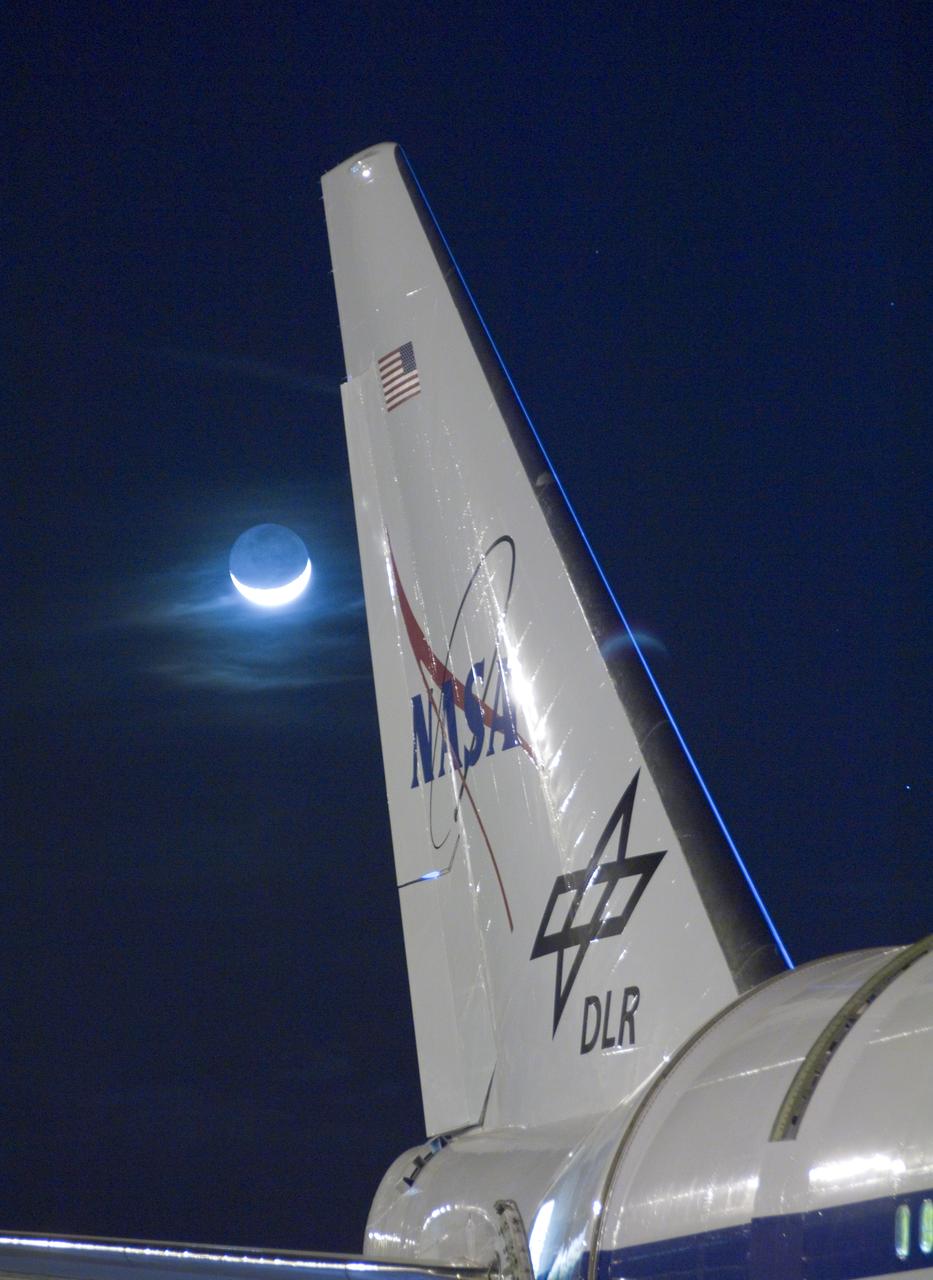
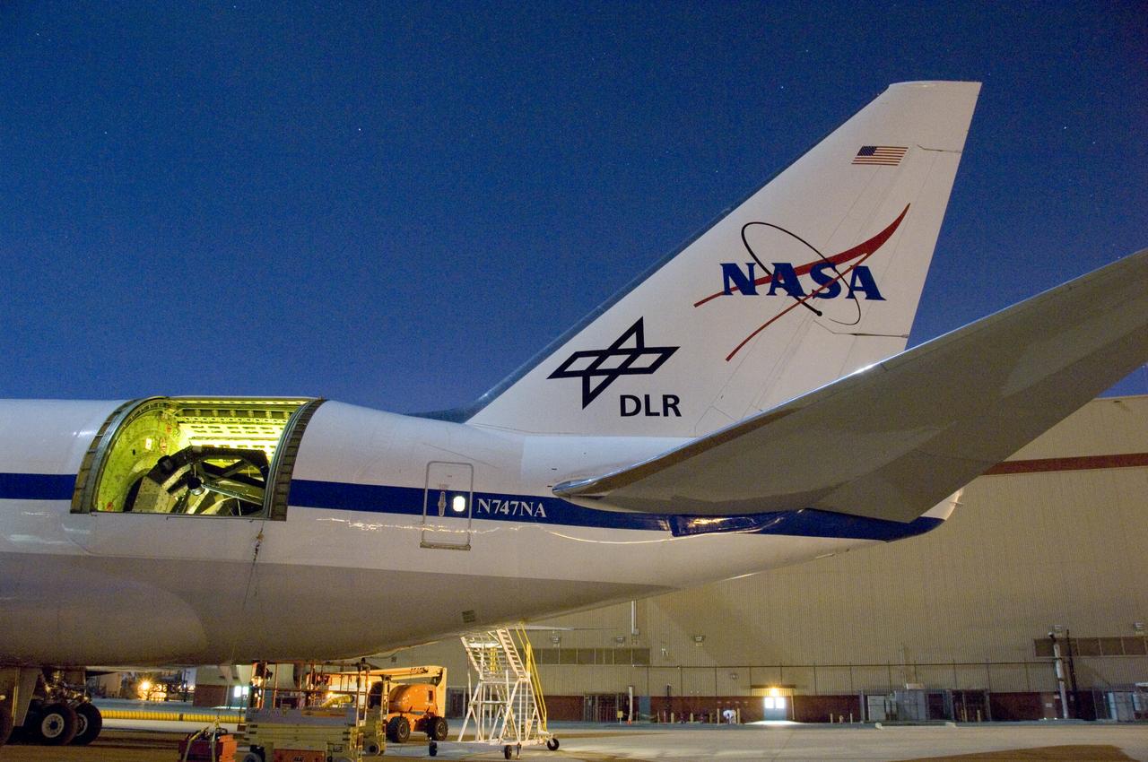
The SOFIA telescope team collected baseline operational measurements during several nights of characterization testing in March 2008 while the SOFIA 747SP aircraft that houses the German-built infrared telescope was parked on an unlit ramp next to its hangar at the NASA Dryden Flight Operations Facility in Palmdale, Calif. The primary celestial target was Polaris, the North Star. The activity provided the team with a working knowledge of how telescope operating systems interact and the experience of tracking celestial targets from the ground.

The SOFIA telescope team collected baseline operational measurements during several nights of characterization testing in March 2008 while the SOFIA 747SP aircraft that houses the German-built infrared telescope was parked on an unlit ramp next to its hangar at the NASA Dryden Flight Operations Facility in Palmdale, Calif. The primary celestial target was Polaris, the North Star. The activity provided the team with a working knowledge of how telescope operating systems interact and the experience of tracking celestial targets from the ground.

The SOFIA telescope team collected baseline operational measurements during several nights of characterization testing in March 2008 while the SOFIA 747SP aircraft that houses the German-built infrared telescope was parked on an unlit ramp next to its hangar at the NASA Dryden Flight Operations Facility in Palmdale, Calif. The primary celestial target was Polaris, the North Star. The activity provided the team with a working knowledge of how telescope operating systems interact and the experience of tracking celestial targets from the ground.

The SOFIA telescope team collected baseline operational measurements during several nights of characterization testing in March 2008 while the SOFIA 747SP aircraft that houses the German-built infrared telescope was parked on an unlit ramp next to its hangar at the NASA Dryden Flight Operations Facility in Palmdale, Calif. The primary celestial target was Polaris, the North Star. The activity provided the team with a working knowledge of how telescope operating systems interact and the experience of tracking celestial targets from the ground.

The SOFIA telescope team collected baseline operational measurements during several nights of characterization testing in March 2008 while the SOFIA 747SP aircraft that houses the German-built infrared telescope was parked on an unlit ramp next to its hangar at the NASA Dryden Flight Operations Facility in Palmdale, Calif. The primary celestial target was Polaris, the North Star. The activity provided the team with a working knowledge of how telescope operating systems interact and the experience of tracking celestial targets from the ground.

The SOFIA telescope team collected baseline operational measurements during several nights of characterization testing in March 2008 while the SOFIA 747SP aircraft that houses the German-built infrared telescope was parked on an unlit ramp next to its hangar at the NASA Dryden Flight Operations Facility in Palmdale, Calif. The primary celestial target was Polaris, the North Star. The activity provided the team with a working knowledge of how telescope operating systems interact and the experience of tracking celestial targets from the ground.

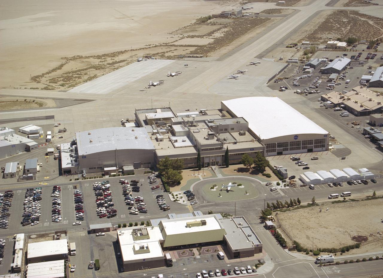
The X-1E research aircraft provides a striking view at the entrance of NASA's Dryden Flight Research Center, Edwards, California. The X-1E, one of the three original X-1 aircraft modified with a raised cockpit canopy and an ejection seat, was flown at the facility between 1953 and 1958 to investigate speeds at twice that of sound, and also to evaluate a thin wing designed for high-speed flight. The Dryden complex was originally established in 1946 as a small high-speed flight station to support the X-1 program. The X-1 was the first aircraft to fly at supersonic speeds. The main administrative building is to the rear of the X-1E and is the center of a research installation that has grown to more than 450 government employees and nearly 400 civilian contractors. Located on the northwest "shore" of Rogers Dry Lake, the Dryden Center was built around the original administrative-hangar building constructed in 1954 at a cost of $3.8 million. Since then many additional support and operational facilities have been built including a number of unique test facilities such as the Thermalstructures Research Facility, Flow Visualization Facility, and the newest addition, the Integrated Test Facility.
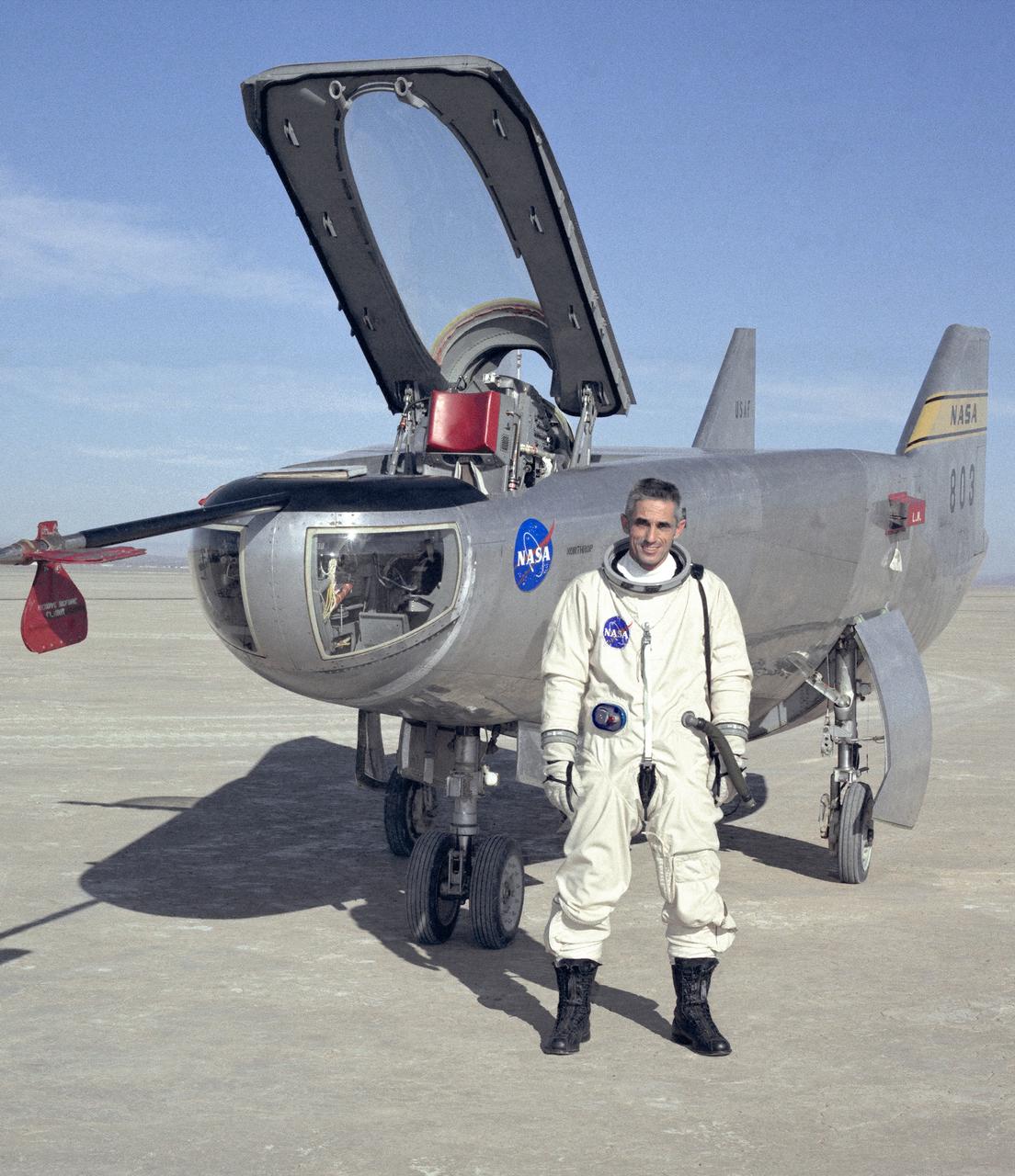
NASA research pilot John A. Manke is seen here in front of the M2-F3 Lifting Body. Manke was hired by NASA on May 25, 1962, as a flight research engineer. He was later assigned to the pilot's office and flew various support aircraft including the F-104, F5D, F-111 and C-47. After leaving the Marine Corps in 1960, Manke worked for Honeywell Corporation as a test engineer for two years before coming to NASA. He was project pilot on the X-24B and also flew the HL-10, M2-F3, and X-24A lifting bodies. John made the first supersonic flight of a lifting body and the first landing of a lifting body on a hard surface runway. Manke served as Director of the Flight Operations and Support Directorate at the Dryden Flight Research Center prior to its integration with Ames Research Center in October 1981. After this date John was named to head the joint Ames-Dryden Directorate of Flight Operations. He also served as site manager of the NASA Ames-Dryden Flight Research Facility. John is a member of the Society of Experimental Test Pilots. He retired on April 27, 1984.
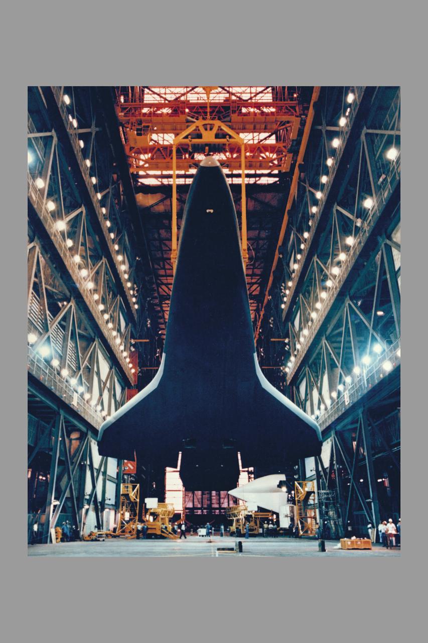
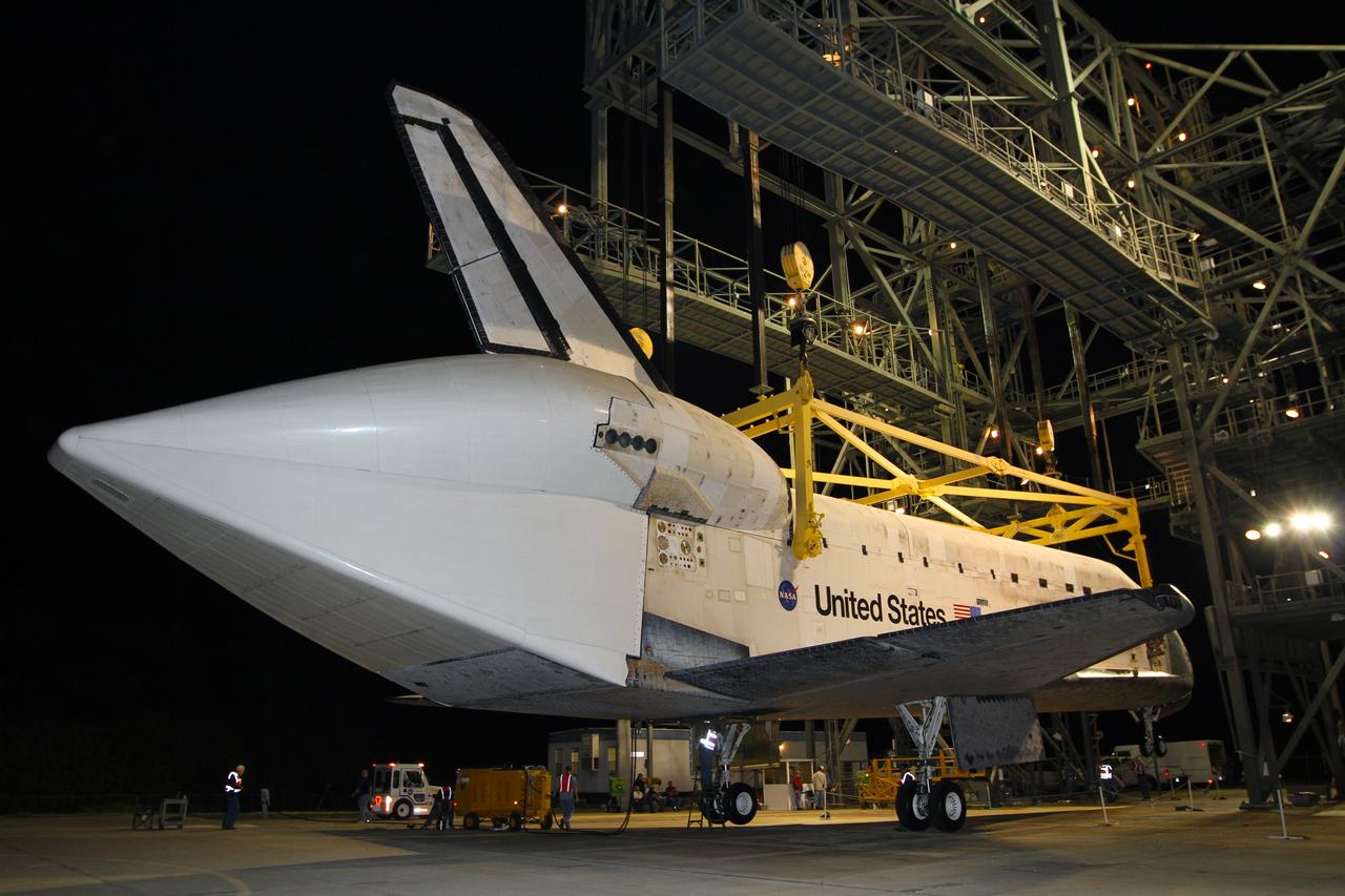
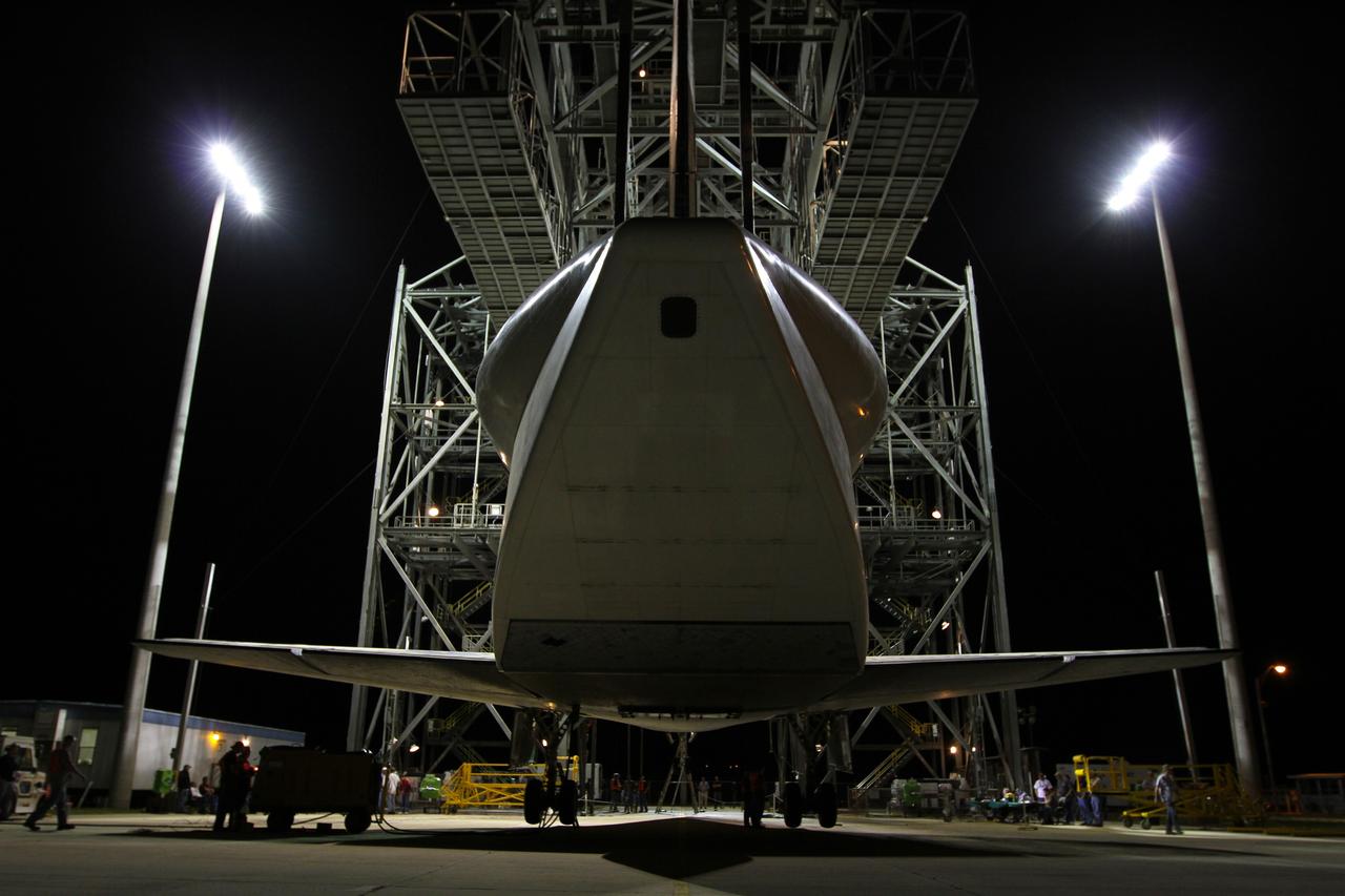
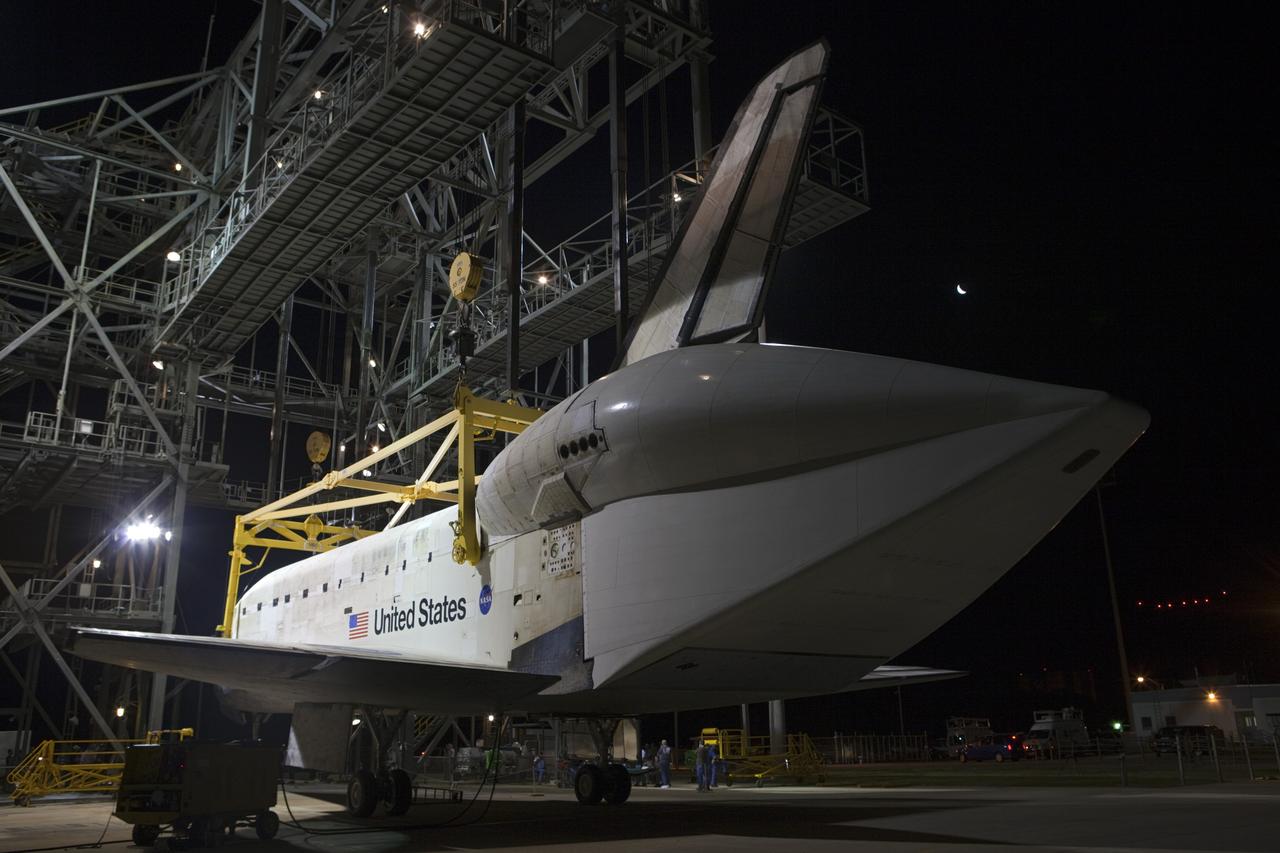
Space Shuttle Orbiter Enterprise is lowered to the floor of the transfer aisle in the Vehicle Assembly Building during destacking operations. The Enterprise, mated to an external tank and twin inert solid rocket boosters, formed a nonlaunchable Space Shuttle which was used for fit and function checks of assembly, test and launch facilities at the nation's Spaceport. Enterprise will be tansported to the Shuttle Landing Facility, mounted piggyback on its 747 Shuttle Carrier Aircraft, and flown to NASA's Dryden Flight Research Center, California.
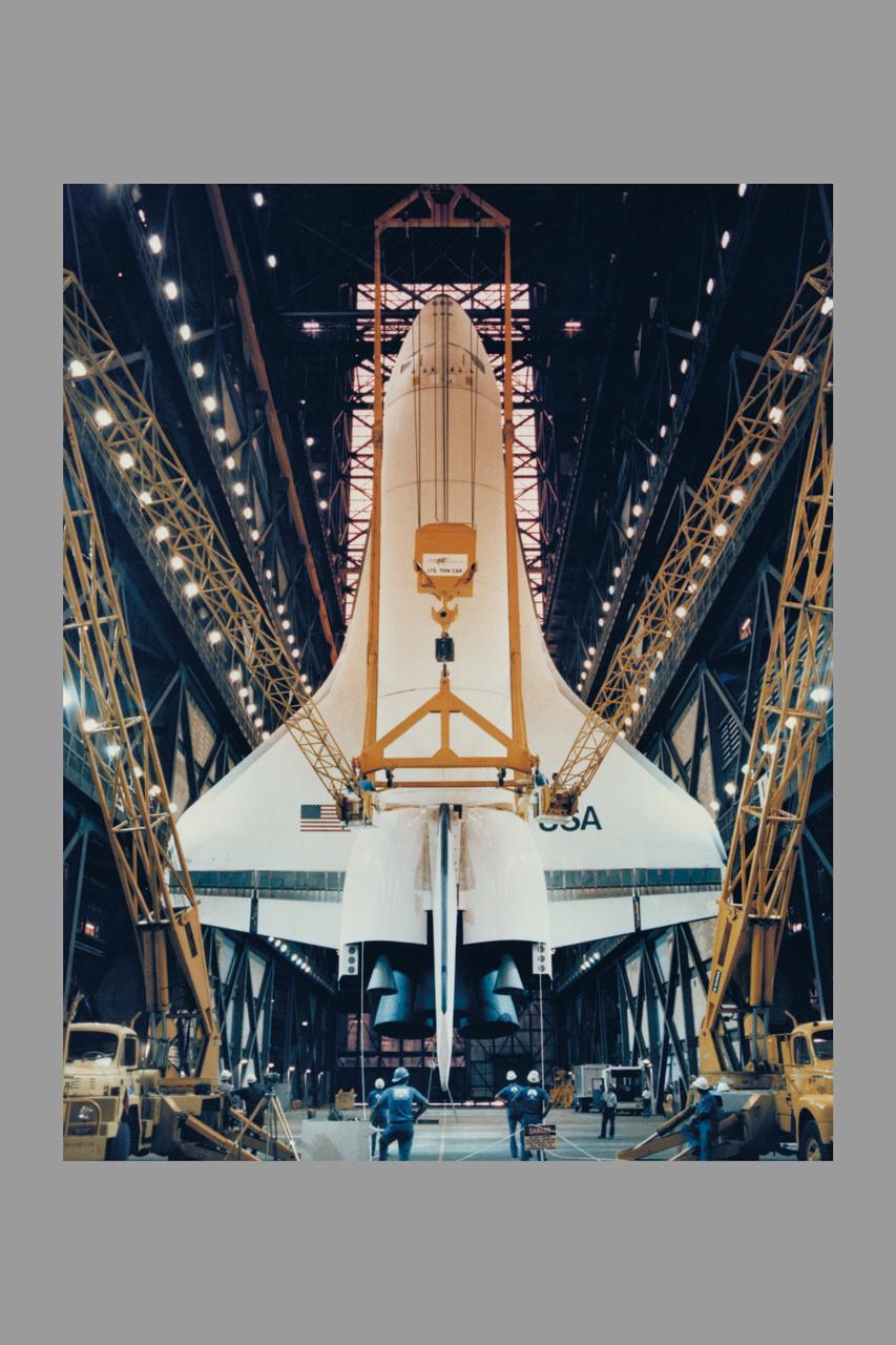
The Space Shuttle Orbiter Enterprise is lowered to the floor of the transfer aisle in the Vehicle Assembly Building during destacking operations. The Enterprise, mated to an external tank and twin inert solid rocket boosters, formed a nonlaunchable Space Shuttle which was used for fit and fuction checks of assembly, test and launch facilities at the nation's Spaceport. Enterprise will be transported to the Shuttle Landing Facility, mounted piggyback on its 747 Shuttle Carrier Aircraft, and flown to NASA's Dryden Flight Research Center, CA.
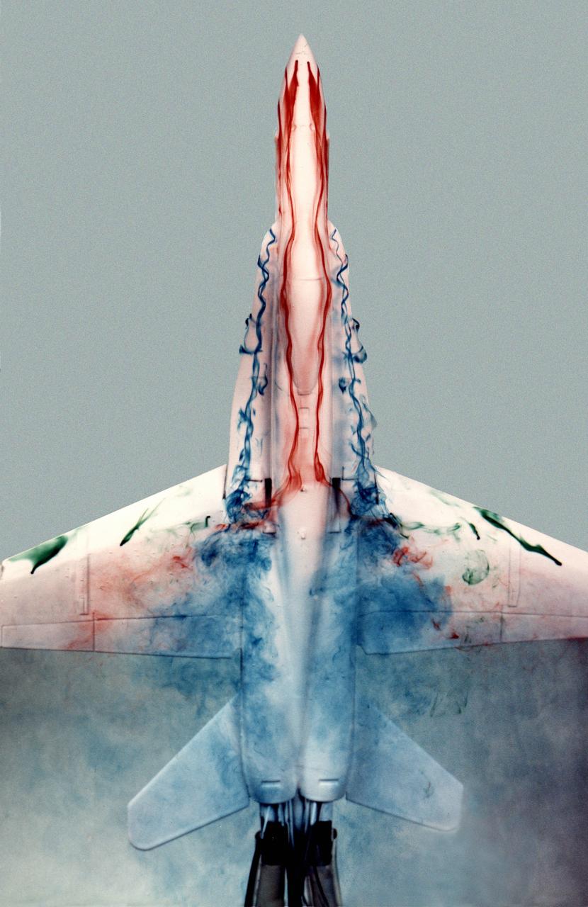
This image shows a plastic 1/48-scale model of an F-18 aircraft inside the "Water Tunnel" more formally known as the NASA Dryden Flow Visualization Facility. Water is pumped through the tunnel in the direction of normal airflow over the aircraft; then, colored dyes are pumped through tubes with needle valves. The dyes flow back along the airframe and over the airfoils highlighting their aerodynamic characteristics. The aircraft can also be moved through its pitch axis to observe airflow disruptions while simulating actual flight at high angles of attack. The Water Tunnel at NASA's Dryden Flight Research Center, Edwards, CA, became operational in 1983 when Dryden was a Flight Research Facility under the management of the Ames Research Center in Mountain View, CA. As a medium for visualizing fluid flow, water has played a significant role. Its use dates back to Leonardo da Vinci (1452-1519), the Renaissance Italian engineer, architect, painter, and sculptor. In more recent times, water tunnels have assisted the study of complex flows and flow-field interactions on aircraft shapes that generate strong vortex flows. Flow visualization in water tunnels assists in determining the strength of vortices, their location, and possible methods of controlling them. The design of the Dryden Water Tunnel imitated that of the Northrop Corporation's tunnel in Hawthorne, CA. Called the Flow Visualization Facility, the Dryden tunnel was built to assist researchers in understanding the aerodynamics of aircraft configured in such a way that they create strong vortex flows, particularly at high angles of attack. The tunnel provides results that compare well with data from aircraft in actual flight in another fluid-air. Other uses of the tunnel have included study of how such flight hardware as antennas, probes, pylons, parachutes, and experimental fixtures affect airflow. The facility has also been helpful in finding the best locations for emitting smoke from flight vehicles for flow vi

A NASA F/A-18, specially modified to test the newest and most advanced system technologies, on its first research flight on May 21, 1993, at NASA's Dryden Flight Research Facility, Edwards, California. Flown by Dryden in a multi-year, joint NASA/DOD/industry program, the F/A-18 former Navy fighter was modified into a unique Systems Research Aircraft (SRA) to investigate a host of new technologies in the areas of flight controls, airdata sensing and advanced computing. The primary goal of the SRA program was to validate through flight research cutting-edge technologies which could benefit future aircraft and spacecraft by improving efficiency and performance, reducing weight and complexity, with a resultant reduction on development and operational costs.
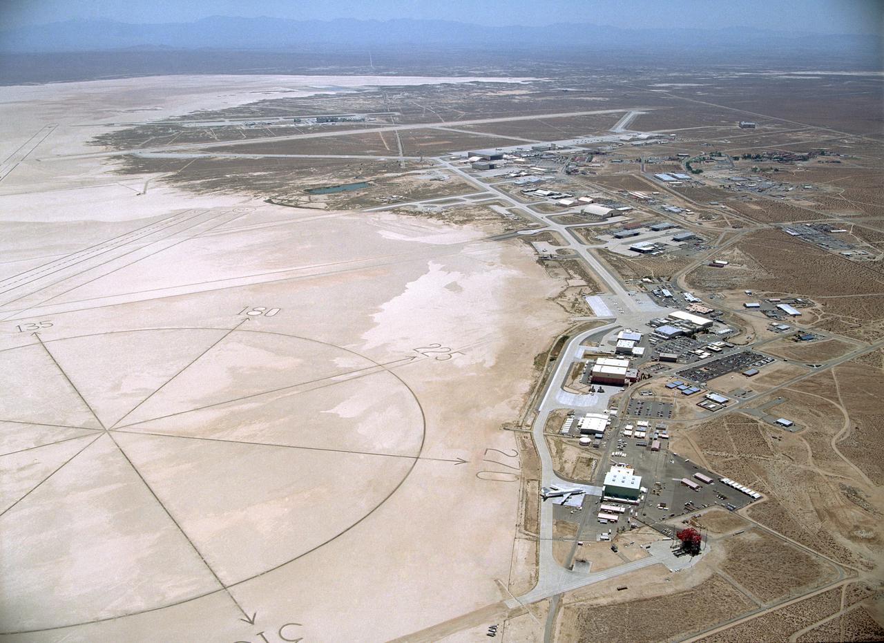
Since the 1940s the Dryden Flight Research Center, Edwards, California, has developed a unique and highly specialized capability for conducting flight research programs. The organization, made up of pilots, scientists, engineers, technicians, and mechanics, has been and will continue to be leaders in the field of advanced aeronautics. Located on the northwest "shore" of Rogers Dry Lake, the complex was built around the original administrative-hangar building constructed in 1954. Since then many additional support and operational facilities have been built including a number of unique test facilities such as the Thermalstructures Research Facility, Flow Visualization Facility, and the Integrated Test Facility. One of the most prominent structures is the space shuttle program's Mate-Demate Device and hangar in Area A to the north of the main complex. On the lakebed surface is a Compass Rose that gives pilots an instant compass heading. The Dryden complex originated at Edwards Air Force Base in support of the X-1 supersonic flight program. As other high-speed aircraft entered research programs, the facility became permanent and grew from a staff of five engineers in 1947 to a population in 2006 of nearly 1100 full-time government and contractor employees.
Since the 1940s the Dryden Flight Research Center, Edwards, California, has developed a unique and highly specialized capability for conducting flight research programs. The organization, made up of pilots, scientists, engineers, technicians, and mechanics, has been and will continue to be leaders in the field of advanced aeronautics. Located on the northwest "shore" of Rogers Dry Lake, the complex was built around the original administrative-hangar building constructed in 1954. Since then many additional support and operational facilities have been built including a number of unique test facilities such as the Thermalstructures Research Facility, Flow Visualization Facility, and the Integrated Test Facility. One of the most prominent structures is the space shuttle program's Mate-Demate Device and hangar in Area A to the north of the main complex. On the lakebed surface is a Compass Rose that gives pilots an instant compass heading. The Dryden complex originated at Edwards Air Force Base in support of the X-1 supersonic flight program. As other high-speed aircraft entered research programs, the facility became permanent and grew from a staff of five engineers in 1947 to a population in 2006 of nearly 1100 full-time government and contractor employees.
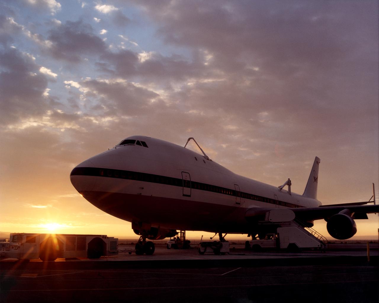
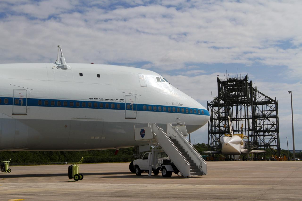
One of NASA’s two modified Boeing 747 Shuttle Carrier Aircraft is bathed in the morning Sun at NASA’s Dryden Flight Research Center at Edwards, California. The modified jumbo jetliners are used to ferry the Space Shuttle orbiters between Dryden and the Kennedy Space Center in Florida and Boeing’s Reusable Space Systems modification facility at Palmdale, California. Features which distinguish the two SCAs from standard 747 jetliners are three struts, with associated interior structural strengthening, which protrude from the top of the fuselage (two aft, one forward) on which the orbiter is attached, and two additional vertical stabilizers, one on each end of the standard horizontal stabilizer, to enhance directional stability. All interior furnishings and equipment aft of the forward No. 1 doors have also been removed to reduce weight. The two SCAs are under the operational control of NASA's Johnson Space Center, Houston, Texas.
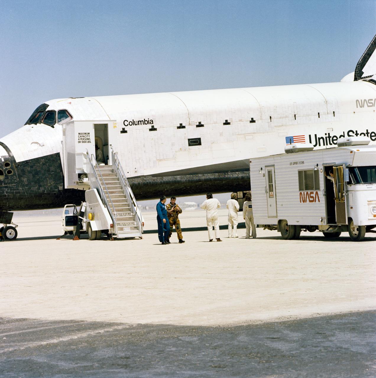
S81-30853 (14 April 1981) --- Astronaut John W. Young, left center talks with George W.S. Abbey, director of flight operations at Johnson Space Center, following egress from the STS-1 Columbia, which forms the backdrop for this postflight scene. Young is en route to the van at right which will take him and fellow crew member Robert L. Crippen (STS-1 pilot still inside Columbia) to facilities at nearby Dryden Flight Research Center. Columbia will be mated to a 747 carrier craft and flown to Florida, where it will be refurbished to accommodate STS-2, scheduled for a Sept. 30 launch date. Photo credit: NASA
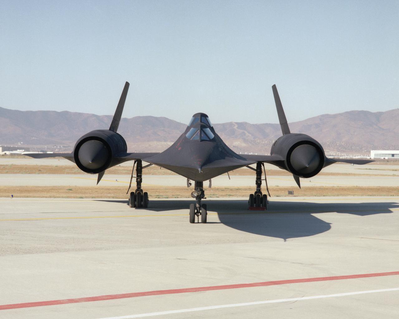
This photo shows a head-on view of NASA's SR-71B, used for pilot proficiency and training, on the ramp at the Air Force's Plant 42 in Palmdale, California, shortly before delivery to the Ames-Dryden Flight Research Facility (later, Dryden Flight Research Center) at Edwards, California. NASA operated two of these unique aircraft, an SR-71A, for high-speed, high altitude research, and this SR- 71B pilot trainer for most of the decade of the 1990s. The "B" model is special because of its raised rear cockpit, which provided a second pilot position so a trainer and an experienced pilot could both see what was going on during flights. The SR-71 was designed and built by the Lockheed Skunk Works, now the Lockheed Martin Skunk Works. Studies have shown that less than 20 percent of the total thrust used to fly at Mach 3 is produced by the basic engine itself. The balance of the total thrust is produced by the unique design of the engine inlet and "moveable spike" system at the front of the engine nacelles, and by the ejector nozzles at the exhaust which burn air compressed in the engine bypass system. Data from the SR-71 high speed research program will be used to aid designers of future supersonic/hypersonic aircraft and propulsion systems, including a high speed civil transport.
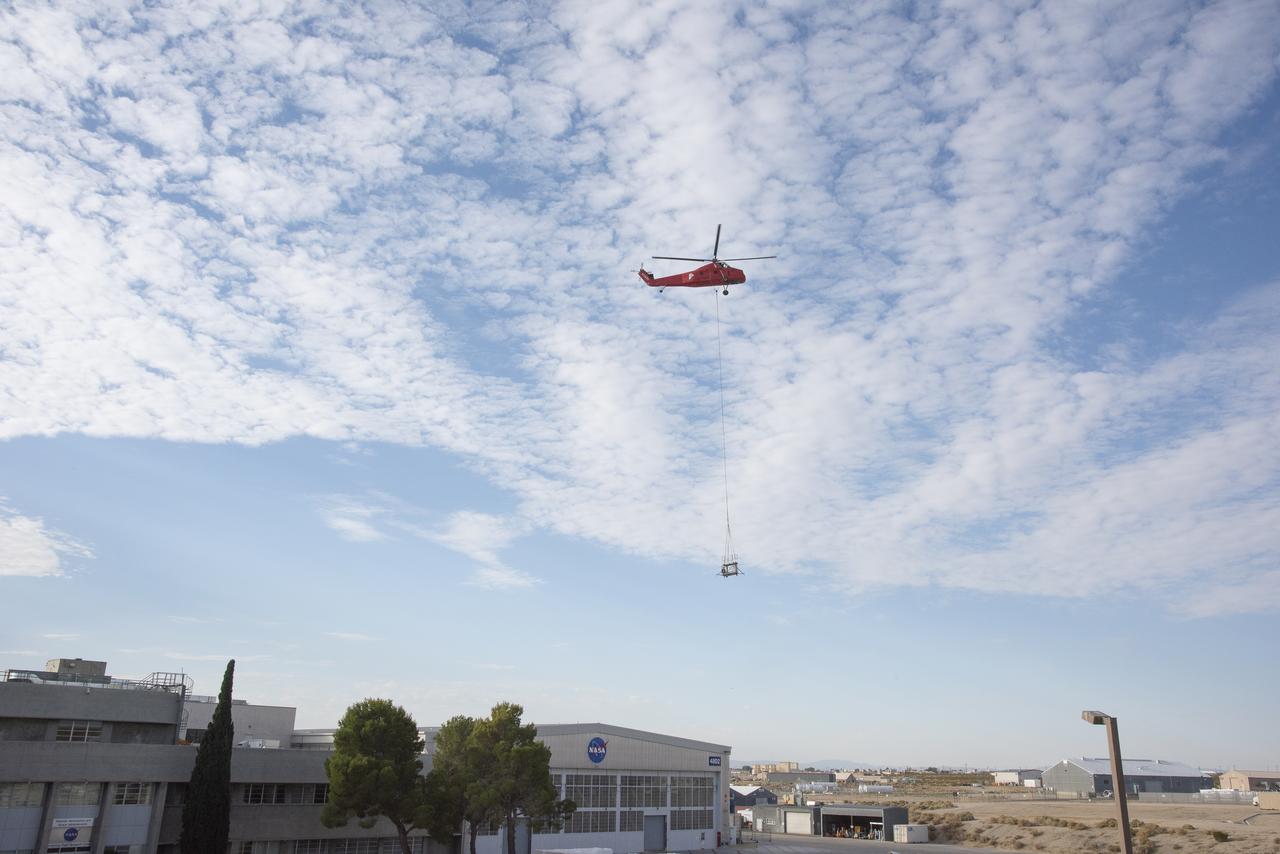
A helicopter carries a rooftop pedestal it removed from Building 4800 at NASA’s Armstrong Flight Research Center in Edwards, California, on Oct. 4, 2024. The pedestal was used since the 1950s to 2015 to house different telemetry dishes to collect data from research aircraft.
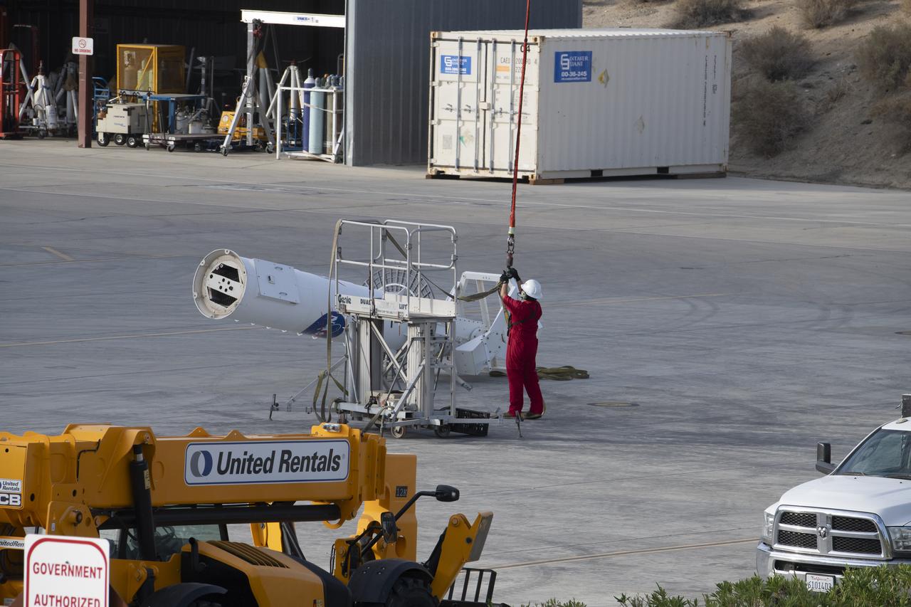
A pedestal carried by a helicopter is positioned for a gentle placement on the ground. The helicopter removed the pedestal from the rooftop of Building 4800 at NASA’s Armstrong Flight Research Center in Edwards, California, on Oct. 4, 2024. The pedestal was used since the 1950s to 2015 to house different telemetry dishes to collect data from research aircraft.
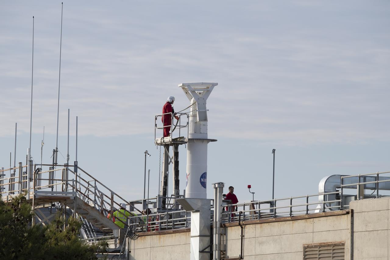
A cable is secured on a rooftop pedestal located on Building 4800 at NASA’s Armstrong Flight Research Center in Edwards, California, on Oct. 4, 2024. The pedestal, which was prepared for a helicopter lift to remove it from the roof, was used since the 1950s until 2015 to enable different telemetry dishes to collect data from research aircraft.
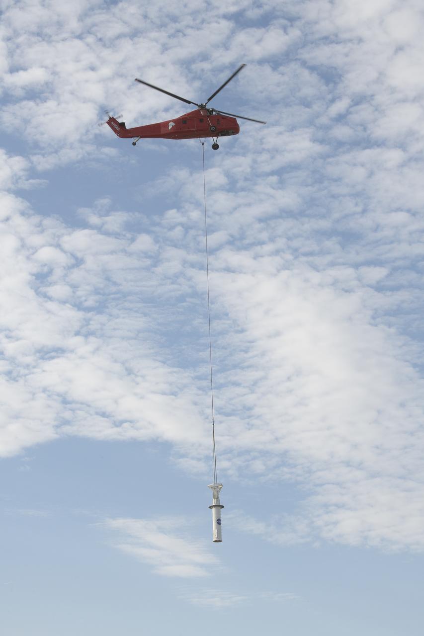
A helicopter carries a rooftop pedestal it removed from Building 4800 at NASA’s Armstrong Flight Research Center in Edwards, California, on Oct. 4, 2024. The pedestal was used since the 1950s to 2015 to house different telemetry dishes to collect data from research aircraft.
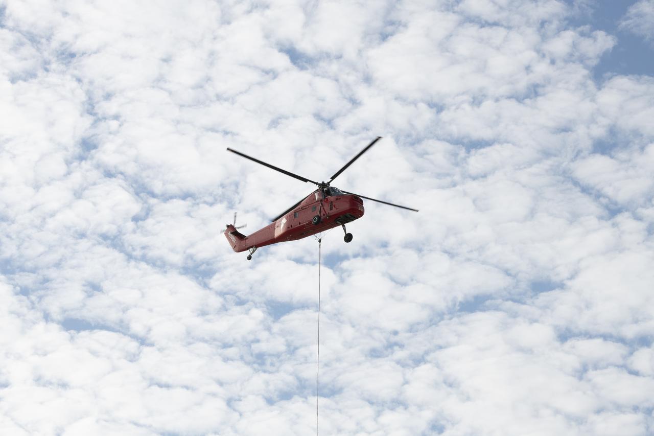
A helicopter is positioned to remove a rooftop pedestal from Building 4800 at NASA’s Armstrong Flight Research Center in Edwards, California, on Oct. 4, 2024. The pedestal was used since the 1950s to 2015 to house different telemetry dishes to collect data from research aircraft.
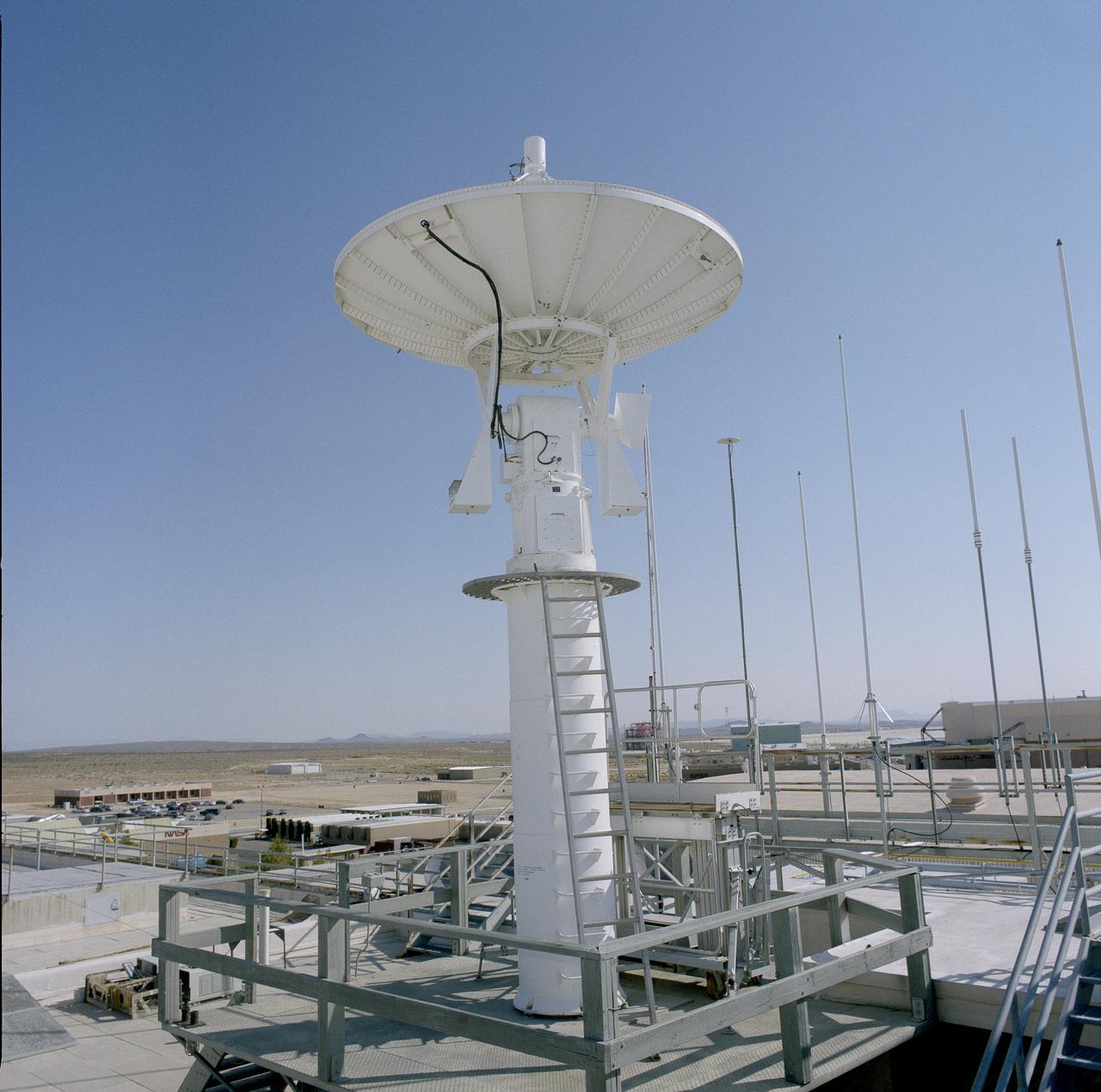
A rooftop pedestal and telemetry dish gathered information from research aircraft at Building 4800 at NASA’s Armstrong Flight Research Center in Edwards, California. The pedestal was used since the 1950s to 2015 to house different dishes to collect data from research aircraft. On Oct. 4, 2024, a helicopter was used to remove the pedestal from the roof.
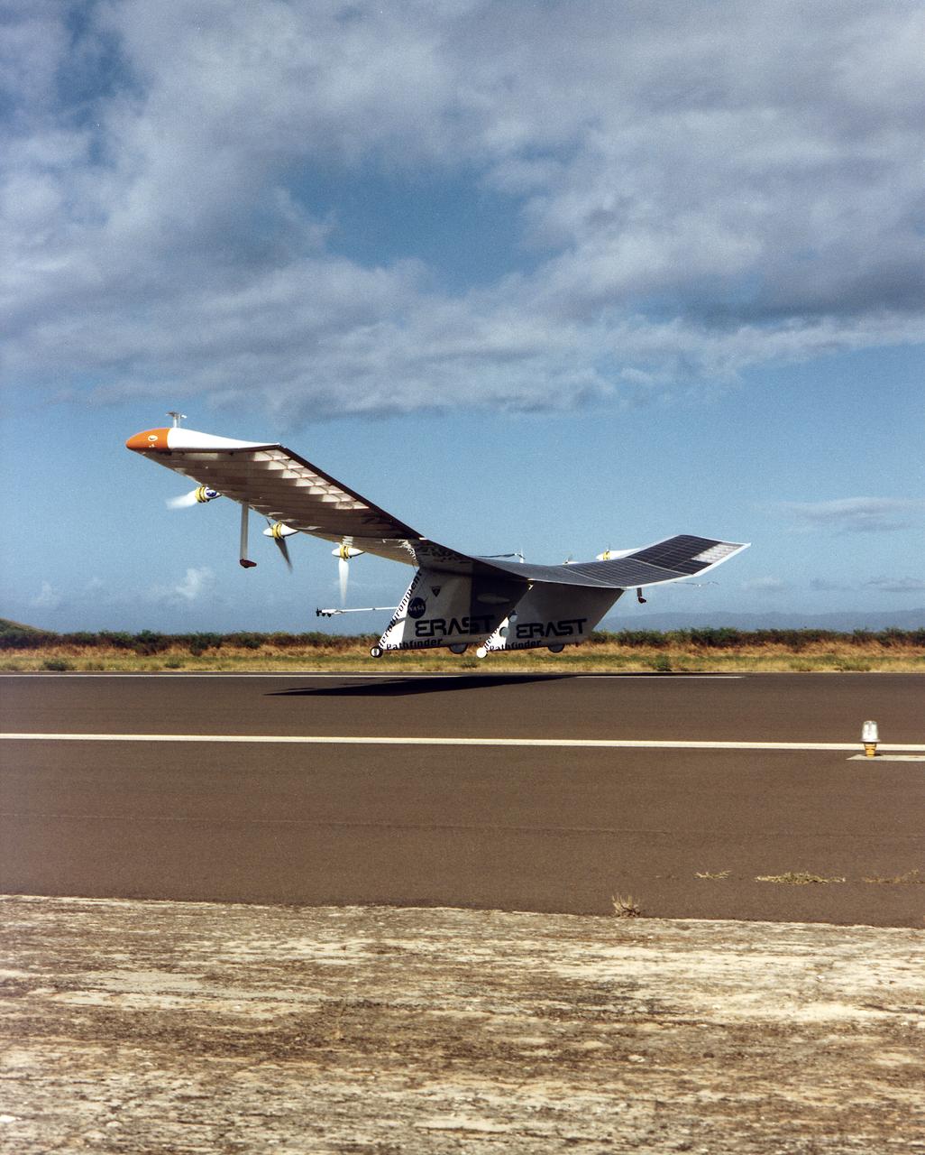
The Pathfinder aircraft has set a new unofficial world record for high-altitude flight of over 71,500 feet for solar-powered aircraft at the U.S. Navy's Pacific Missile Range Facility, Kauai, Hawaii. Pathfinder was designed and manufactured by AeroVironment, Inc, of Simi Valley, California, and was operated by the firm under a jointly sponsored research agreement with NASA's Dryden Flight Research Center, Edwards, California. Pathfinder's record-breaking flight occurred July 7, 1997. The aircraft took off at 11:34 a.m. PDT, passed its previous record altitude of 67,350 feet at about 5:45 p.m. and then reached its new record altitude at 7 p.m. The mission ended with a perfect nighttime landing at 2:05 a.m. PDT July 8. The new record is the highest altitude ever attained by a propellor-driven aircraft. Before Pathfinder, the altitude record for propellor-driven aircraft was 67,028 feet, set by the experimental Boeing Condor remotely piloted aircraft.
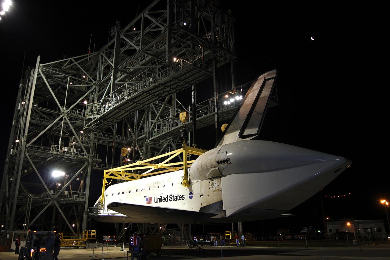
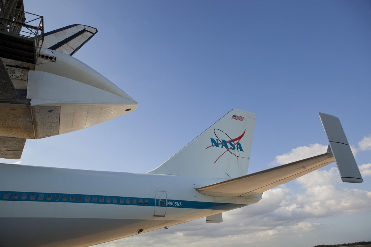
CAPE CANAVERAL, Fla. – At the Shuttle Landing Facility at NASA’s Kennedy Space Center in Florida, painted graphics line the side of NASA 905 depicting the various ferry flights the Shuttle Carrier Aircraft has supported during the Space Shuttle Program, including the tests using the space shuttle prototype Enterprise, and the names of the pilots and flight engineers who have flown it. Operations are under way at the mate-demate device, in the background, to lift Discovery on top of the aircraft. The device, known as the MDD, is a large gantry-like steel structure used to hoist a shuttle off the ground and position it onto the back of the aircraft, or SCA. The SCA is a Boeing 747 jet, originally manufactured for commercial use, which was modified by NASA to transport the shuttles between destinations on Earth. The SCA designated NASA 905 is assigned to the remaining ferry missions, delivering the shuttles to their permanent public display sites. NASA 905 is scheduled to ferry Discovery to the Washington Dulles International Airport in Virginia on April 17, after which the shuttle will be placed on display in the Smithsonian's National Air and Space Museum Steven F. Udvar-Hazy Center. For more information on the SCA, visit http://www.nasa.gov/centers/dryden/news/FactSheets/FS-013-DFRC.html. For more information on shuttle transition and retirement activities, visit http://www.nasa.gov/transition. Photo credit: NASA/Kim Shiflett
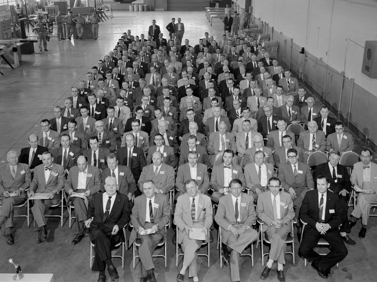
Attendees listen during the May 22, 1956 Inspection of the new 10- by 10-Foot Supersonic Wind Tunnel at the National Advisory Committee for Aeronautics (NACA) Lewis Flight Propulsion Laboratory. The facility, known at the time as the Lewis Unitary Plan Tunnel, was in its initial stages of operation. The $33 million 10- by 10 was the most powerful wind tunnel in the nation. Over 150 guests from industry, other NACA laboratories, and the media attended the event. The speakers, from left to right in the front row, addressed the crowd before the tour. Lewis Director Raymond Sharp began the event by welcoming the visitors to the laboratory. NACA Director Hugh Dryden discussed Congress’ Unitary Plan Act and its effect on the creation of the facility. Lewis Associate Director Abe Silverstein discussed the need for research tools and the 10- by 10’s place among the NACA’s other research facilities. Lewis Assistant Director Eugene Wasielewski described the detailed design work that went into the facility. Carl Schueller, Chief of the 10- by 10, described the tunnel’s components and how the facility operated. Robert Godman led the tour afterwards. The 10- by 10 can test engines up to five feet in diameter at supersonic speeds and simulated altitudes of 30 miles. Its main purpose is to investigate problems relating to engine inlet and outlet geometry, engine matching and interference effects, and overall drag. The tunnel’s 250,000-horsepower electric motor drive, the most powerful of its kind in the world, creates air speeds between Mach 2.0 and 3.5.
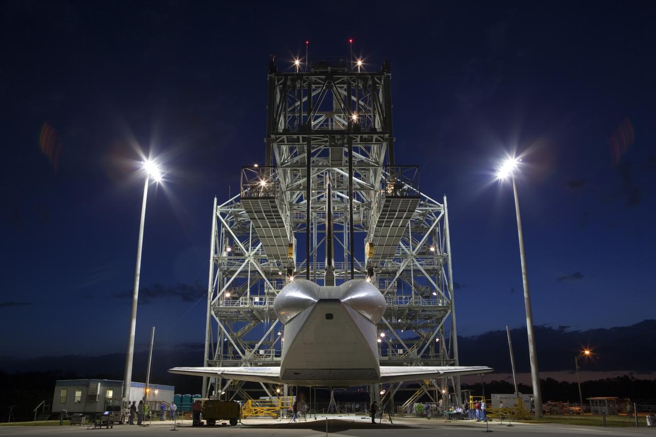
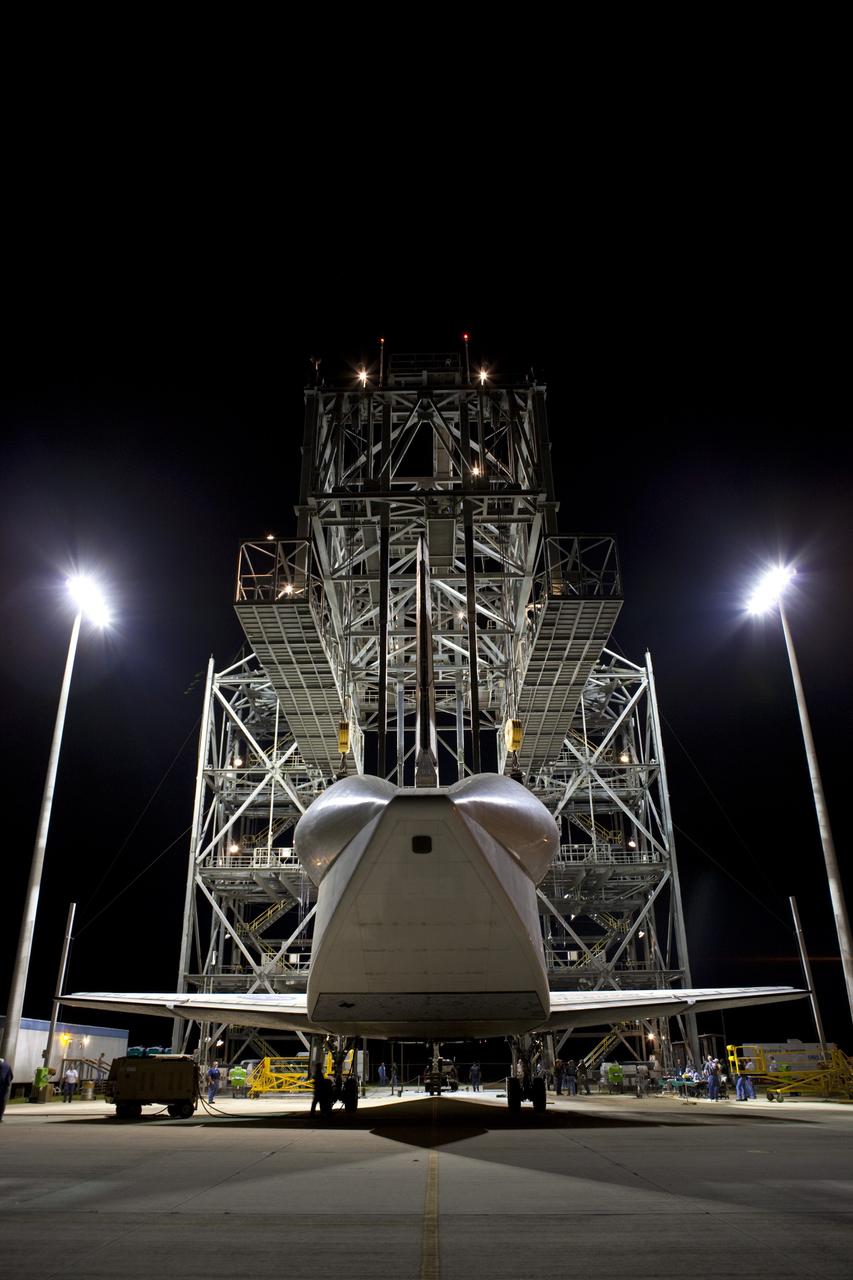
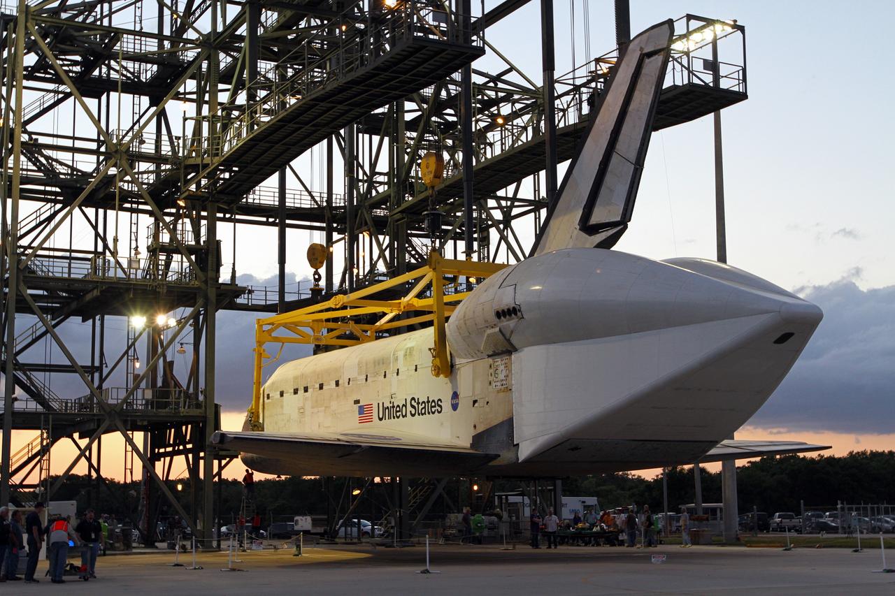
CAPE CANAVERAL, Fla. – Before daybreak at the Shuttle Landing Facility at NASA’s Kennedy Space Center in Florida, space shuttle Discovery hovers above the ground at the mate-demate device. Operations are under way to position Discovery on top of a Shuttle Carrier Aircraft in preparation for its departure from Kennedy on Tuesday. A tail cone has been installed over Discovery’s three replica shuttle main engines to reduce aerodynamic drag and turbulence during the ferry flight. The device, known as the MDD, is a large gantry-like steel structure used to hoist a shuttle off the ground and position it onto the back of the aircraft, or SCA. The SCA is a Boeing 747 jet, originally manufactured for commercial use, which was modified by NASA to transport the shuttles between destinations on Earth. The SCA designated NASA 905 is assigned to the remaining ferry missions, delivering the shuttles to their permanent public display sites. NASA 905 is scheduled to ferry Discovery to the Washington Dulles International Airport in Virginia on April 17, after which the shuttle will be placed on display in the Smithsonian's National Air and Space Museum Steven F. Udvar-Hazy Center. For more information on the SCA, visit http://www.nasa.gov/centers/dryden/news/FactSheets/FS-013-DFRC.html. For more information on shuttle transition and retirement activities, visit http://www.nasa.gov/transition. Photo credit: NASA/Dimitri Gerondidakis

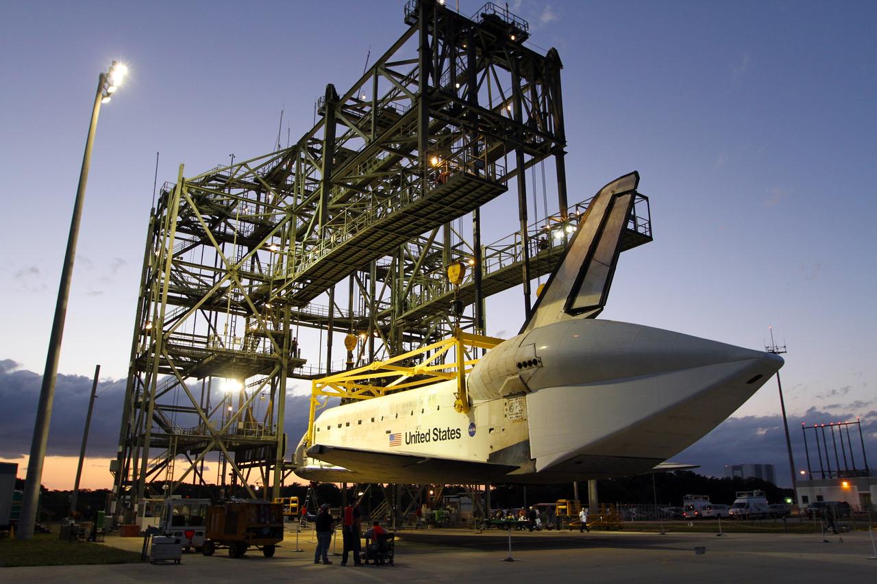
CAPE CANAVERAL, Fla. – Before sunrise at the Shuttle Landing Facility at NASA’s Kennedy Space Center in Florida, lights on the mate-demate device reveal space shuttle Discovery suspended above the ground. Operations are under way to place Discovery on top of a Shuttle Carrier Aircraft in preparation for its departure from Kennedy on Tuesday. A tail cone has been installed over Discovery’s three replica shuttle main engines to reduce aerodynamic drag and turbulence during the ferry flight. The device, known as the MDD, is a large gantry-like steel structure used to hoist a shuttle off the ground and position it onto the back of the aircraft, or SCA. The SCA is a Boeing 747 jet, originally manufactured for commercial use, which was modified by NASA to transport the shuttles between destinations on Earth. The SCA designated NASA 905 is assigned to the remaining ferry missions, delivering the shuttles to their permanent public display sites. NASA 905 is scheduled to ferry Discovery to the Washington Dulles International Airport in Virginia on April 17, after which the shuttle will be placed on display in the Smithsonian's National Air and Space Museum Steven F. Udvar-Hazy Center. For more information on the SCA, visit http://www.nasa.gov/centers/dryden/news/FactSheets/FS-013-DFRC.html. For more information on shuttle transition and retirement activities, visit http://www.nasa.gov/transition. Photo credit: NASA/Kim Shiflett
CAPE CANAVERAL, Fla. – Before daybreak at the Shuttle Landing Facility at NASA’s Kennedy Space Center in Florida, preparations are under way at the mate-demate device to resume mating operations of space shuttle Discovery to a Shuttle Carrier Aircraft. A tail cone covers Discovery’s three replica shuttle main engines to reduce aerodynamic drag and turbulence during the ferry flight. The device, known as the MDD, is a large gantry-like steel structure used to hoist a shuttle off the ground and position it onto the back of the aircraft, or SCA. The SCA is a Boeing 747 jet, originally manufactured for commercial use, which was modified by NASA to transport the shuttles between destinations on Earth. The SCA designated NASA 905 is assigned to the remaining ferry missions, delivering the shuttles to their permanent public display sites. NASA 905 is scheduled to ferry Discovery to the Washington Dulles International Airport in Virginia on April 17, after which the shuttle will be placed on display in the Smithsonian's National Air and Space Museum Steven F. Udvar-Hazy Center. For more information on the SCA, visit http://www.nasa.gov/centers/dryden/news/FactSheets/FS-013-DFRC.html. For more information on shuttle transition and retirement activities, visit http://www.nasa.gov/transition. Photo credit: NASA/Dimitri Gerondidakis
CAPE CANAVERAL, Fla. – Before daybreak at the Shuttle Landing Facility at NASA’s Kennedy Space Center in Florida, operations are under way at the mate-demate device to lift space shuttle Discovery on top of a Shuttle Carrier Aircraft. A tail cone has been installed over Discovery’s three replica shuttle main engines to reduce aerodynamic drag and turbulence during the ferry flight. The device, known as the MDD, is a large gantry-like steel structure used to hoist a shuttle off the ground and position it onto the back of the aircraft, or SCA. The SCA is a Boeing 747 jet, originally manufactured for commercial use, which was modified by NASA to transport the shuttles between destinations on Earth. The SCA designated NASA 905 is assigned to the remaining ferry missions, delivering the shuttles to their permanent public display sites. NASA 905 is scheduled to ferry Discovery to the Washington Dulles International Airport in Virginia on April 17, after which the shuttle will be placed on display in the Smithsonian's National Air and Space Museum Steven F. Udvar-Hazy Center. For more information on the SCA, visit http://www.nasa.gov/centers/dryden/news/FactSheets/FS-013-DFRC.html. For more information on shuttle transition and retirement activities, visit http://www.nasa.gov/transition. Photo credit: NASA/Dimitri Gerondidakis
CAPE CANAVERAL, Fla. – Before sunrise at the Shuttle Landing Facility at NASA’s Kennedy Space Center in Florida, space shuttle Discovery is lifted into the mate-demate device by a crane hooked to the yellow sling. Operations have resumed to place Discovery on top of a Shuttle Carrier Aircraft in preparation for its departure from Kennedy on Tuesday. A tail cone has been installed over Discovery’s three replica shuttle main engines to reduce aerodynamic drag and turbulence during the ferry flight. The device, known as the MDD, is a large gantry-like steel structure used to hoist a shuttle off the ground and position it onto the back of the aircraft, or SCA. The SCA is a Boeing 747 jet, originally manufactured for commercial use, which was modified by NASA to transport the shuttles between destinations on Earth. The SCA designated NASA 905 is assigned to the remaining ferry missions, delivering the shuttles to their permanent public display sites. NASA 905 is scheduled to ferry Discovery to the Washington Dulles International Airport in Virginia on April 17, after which the shuttle will be placed on display in the Smithsonian's National Air and Space Museum Steven F. Udvar-Hazy Center. For more information on the SCA, visit http://www.nasa.gov/centers/dryden/news/FactSheets/FS-013-DFRC.html. For more information on shuttle transition and retirement activities, visit http://www.nasa.gov/transition. Photo credit: NASA/Kim Shiflett
CAPE CANAVERAL, Fla. – Before daybreak at the Shuttle Landing Facility at NASA’s Kennedy Space Center in Florida, space shuttle Discovery hovers above the ground at the mate-demate device. Operations are under way to position Discovery on top of a Shuttle Carrier Aircraft in preparation for its departure from Kennedy on Tuesday. A tail cone has been installed over Discovery’s three replica shuttle main engines to reduce aerodynamic drag and turbulence during the ferry flight. The device, known as the MDD, is a large gantry-like steel structure used to hoist a shuttle off the ground and position it onto the back of the aircraft, or SCA. The SCA is a Boeing 747 jet, originally manufactured for commercial use, which was modified by NASA to transport the shuttles between destinations on Earth. The SCA designated NASA 905 is assigned to the remaining ferry missions, delivering the shuttles to their permanent public display sites. NASA 905 is scheduled to ferry Discovery to the Washington Dulles International Airport in Virginia on April 17, after which the shuttle will be placed on display in the Smithsonian's National Air and Space Museum Steven F. Udvar-Hazy Center. For more information on the SCA, visit http://www.nasa.gov/centers/dryden/news/FactSheets/FS-013-DFRC.html. For more information on shuttle transition and retirement activities, visit http://www.nasa.gov/transition. Photo credit: NASA/Dimitri Gerondidakis
CAPE CANAVERAL, Fla. – At the Shuttle Landing Facility at NASA’s Kennedy Space Center in Florida, the tail cone on space shuttle Discovery and the tail of the Shuttle Carrier Aircraft are aligned in the mate-demate device as mating operations get under way. The tail cone has been installed over Discovery’s three replica shuttle main engines to reduce aerodynamic drag and turbulence during the ferry flight. The device, known as the MDD, is a large gantry-like steel structure used to hoist a shuttle off the ground and position it onto the back of the aircraft, or SCA. The SCA is a Boeing 747 jet, originally manufactured for commercial use, which was modified by NASA to transport the shuttles between destinations on Earth. This SCA, designated NASA 905, is assigned to the remaining ferry missions, delivering the shuttles to their permanent public display sites. NASA 905 is scheduled to ferry Discovery to the Washington Dulles International Airport in Virginia on April 17, after which the shuttle will be placed on display in the Smithsonian's National Air and Space Museum Steven F. Udvar-Hazy Center. For more information on the SCA, visit http://www.nasa.gov/centers/dryden/news/FactSheets/FS-013-DFRC.html. For more information on shuttle transition and retirement activities, visit http://www.nasa.gov/transition. Photo credit: NASA/Dimitri Gerondidakis
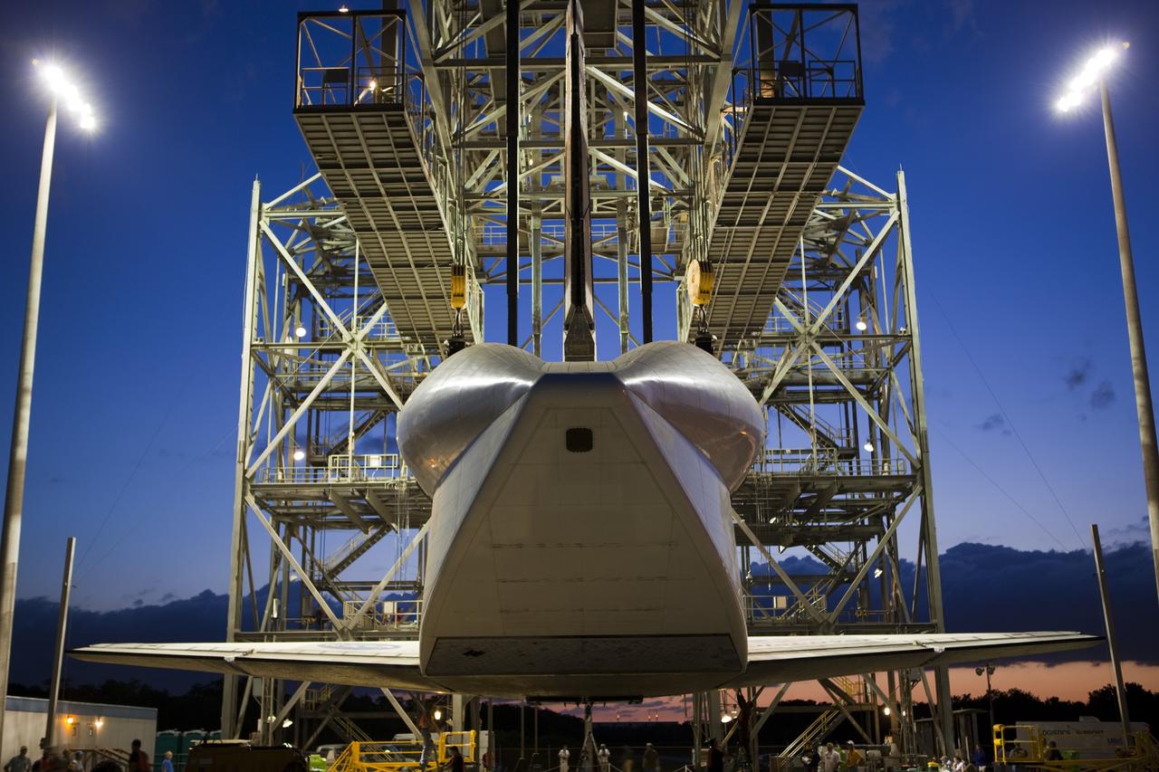
CAPE CANAVERAL, Fla. – As the sun comes up over the Shuttle Landing Facility at NASA’s Kennedy Space Center in Florida, space shuttle Discovery is suspended above the ground at the mate-demate device during operations to place it on top of a Shuttle Carrier Aircraft. A tail cone has been installed over Discovery’s three replica shuttle main engines to reduce aerodynamic drag and turbulence during the ferry flight. The device, known as the MDD, is a large gantry-like steel structure used to hoist a shuttle off the ground and position it onto the back of the aircraft, or SCA. The SCA is a Boeing 747 jet, originally manufactured for commercial use, which was modified by NASA to transport the shuttles between destinations on Earth. The SCA designated NASA 905 is assigned to the remaining ferry missions, delivering the shuttles to their permanent public display sites. NASA 905 is scheduled to ferry Discovery to the Washington Dulles International Airport in Virginia on April 17, after which the shuttle will be placed on display in the Smithsonian's National Air and Space Museum Steven F. Udvar-Hazy Center. For more information on the SCA, visit http://www.nasa.gov/centers/dryden/news/FactSheets/FS-013-DFRC.html. For more information on shuttle transition and retirement activities, visit http://www.nasa.gov/transition. Photo credit: NASA/Kim Shiflett

CAPE CANAVERAL, Fla. – As the sun rises over the Shuttle Landing Facility at NASA’s Kennedy Space Center in Florida, operations are under way at the mate-demate device to lift space shuttle Discovery on top of a Shuttle Carrier Aircraft in preparation for its departure from Kennedy on Tuesday. A tail cone has been installed over Discovery’s three replica shuttle main engines to reduce aerodynamic drag and turbulence during the ferry flight. The device, known as the MDD, is a large gantry-like steel structure used to hoist a shuttle off the ground and position it onto the back of the aircraft, or SCA. The SCA is a Boeing 747 jet, originally manufactured for commercial use, which was modified by NASA to transport the shuttles between destinations on Earth. The SCA designated NASA 905 is assigned to the remaining ferry missions, delivering the shuttles to their permanent public display sites. NASA 905 is scheduled to ferry Discovery to the Washington Dulles International Airport in Virginia on April 17, after which the shuttle will be placed on display in the Smithsonian's National Air and Space Museum Steven F. Udvar-Hazy Center. For more information on the SCA, visit http://www.nasa.gov/centers/dryden/news/FactSheets/FS-013-DFRC.html. For more information on shuttle transition and retirement activities, visit http://www.nasa.gov/transition. Photo credit: NASA/Kim Shiflett
CAPE CANAVERAL, Fla. – As the sun rises over the Shuttle Landing Facility at NASA’s Kennedy Space Center in Florida, operations are under way at the mate-demate device to lift space shuttle Discovery on top of a Shuttle Carrier Aircraft in preparation for its departure from Kennedy on Tuesday. A tail cone has been installed over Discovery’s three replica shuttle main engines to reduce aerodynamic drag and turbulence during the ferry flight. The device, known as the MDD, is a large gantry-like steel structure used to hoist a shuttle off the ground and position it onto the back of the aircraft, or SCA. The SCA is a Boeing 747 jet, originally manufactured for commercial use, which was modified by NASA to transport the shuttles between destinations on Earth. The SCA designated NASA 905 is assigned to the remaining ferry missions, delivering the shuttles to their permanent public display sites. NASA 905 is scheduled to ferry Discovery to the Washington Dulles International Airport in Virginia on April 17, after which the shuttle will be placed on display in the Smithsonian's National Air and Space Museum Steven F. Udvar-Hazy Center. For more information on the SCA, visit http://www.nasa.gov/centers/dryden/news/FactSheets/FS-013-DFRC.html. For more information on shuttle transition and retirement activities, visit http://www.nasa.gov/transition. Photo credit: NASA/Kim Shiflett
CAPE CANAVERAL, Fla. – As the sun rises over the Shuttle Landing Facility at NASA’s Kennedy Space Center in Florida, operations are under way at the mate-demate device to lift space shuttle Discovery on top of a Shuttle Carrier Aircraft. A tail cone has been installed over Discovery’s three replica shuttle main engines to reduce aerodynamic drag and turbulence during the ferry flight. The device, known as the MDD, is a large gantry-like steel structure used to hoist a shuttle off the ground and position it onto the back of the aircraft, or SCA. The SCA is a Boeing 747 jet, originally manufactured for commercial use, which was modified by NASA to transport the shuttles between destinations on Earth. The SCA designated NASA 905 is assigned to the remaining ferry missions, delivering the shuttles to their permanent public display sites. NASA 905 is scheduled to ferry Discovery to the Washington Dulles International Airport in Virginia on April 17, after which the shuttle will be placed on display in the Smithsonian's National Air and Space Museum Steven F. Udvar-Hazy Center. For more information on the SCA, visit http://www.nasa.gov/centers/dryden/news/FactSheets/FS-013-DFRC.html. For more information on shuttle transition and retirement activities, visit http://www.nasa.gov/transition. Photo credit: NASA/Dimitri Gerondidakis
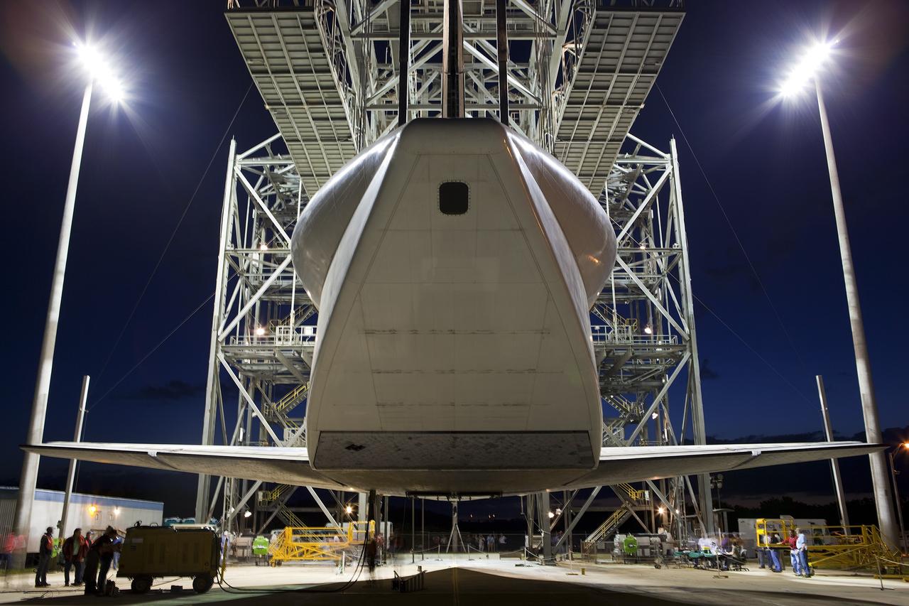
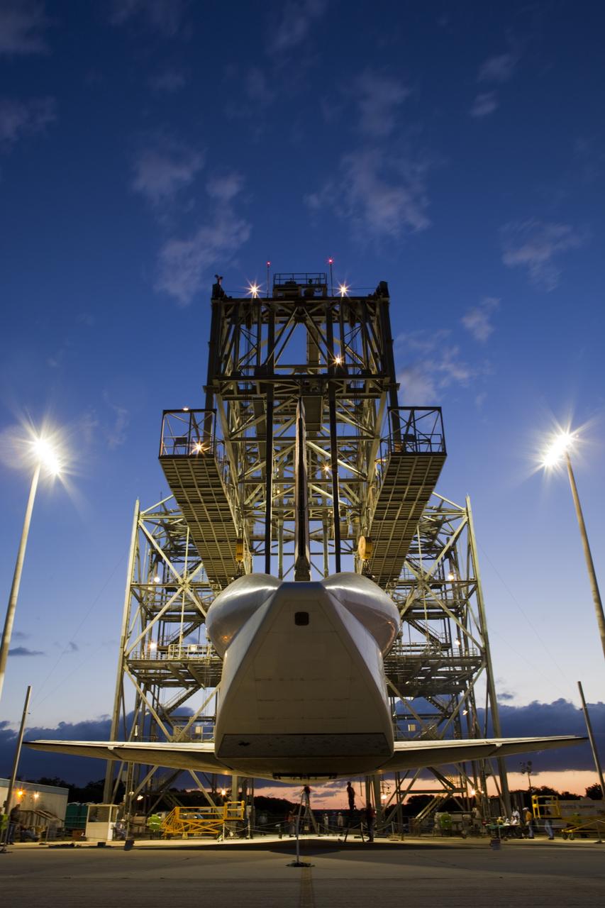
CAPE CANAVERAL, Fla. – Before daybreak at the Shuttle Landing Facility at NASA’s Kennedy Space Center in Florida, a crane on the mate-demate device lifts space shuttle Discovery from the ground. Operations are under way to position Discovery on top of a Shuttle Carrier Aircraft in preparation for its departure from Kennedy on Tuesday. A tail cone has been installed over Discovery’s three replica shuttle main engines to reduce aerodynamic drag and turbulence during the ferry flight. The device, known as the MDD, is a large gantry-like steel structure used to hoist a shuttle off the ground and position it onto the back of the aircraft, or SCA. The SCA is a Boeing 747 jet, originally manufactured for commercial use, which was modified by NASA to transport the shuttles between destinations on Earth. The SCA designated NASA 905 is assigned to the remaining ferry missions, delivering the shuttles to their permanent public display sites. NASA 905 is scheduled to ferry Discovery to the Washington Dulles International Airport in Virginia on April 17, after which the shuttle will be placed on display in the Smithsonian's National Air and Space Museum Steven F. Udvar-Hazy Center. For more information on the SCA, visit http://www.nasa.gov/centers/dryden/news/FactSheets/FS-013-DFRC.html. For more information on shuttle transition and retirement activities, visit http://www.nasa.gov/transition. Photo credit: NASA/Kim Shiflett
CAPE CANAVERAL, Fla. – Before daybreak at the Shuttle Landing Facility at NASA’s Kennedy Space Center in Florida, space shuttle Discovery hovers above the ground at the mate-demate device. Operations are under way to position Discovery on top of a Shuttle Carrier Aircraft in preparation for its departure from Kennedy on Tuesday. A tail cone has been installed over Discovery’s three replica shuttle main engines to reduce aerodynamic drag and turbulence during the ferry flight. The device, known as the MDD, is a large gantry-like steel structure used to hoist a shuttle off the ground and position it onto the back of the aircraft, or SCA. The SCA is a Boeing 747 jet, originally manufactured for commercial use, which was modified by NASA to transport the shuttles between destinations on Earth. The SCA designated NASA 905 is assigned to the remaining ferry missions, delivering the shuttles to their permanent public display sites. NASA 905 is scheduled to ferry Discovery to the Washington Dulles International Airport in Virginia on April 17, after which the shuttle will be placed on display in the Smithsonian's National Air and Space Museum Steven F. Udvar-Hazy Center. For more information on the SCA, visit http://www.nasa.gov/centers/dryden/news/FactSheets/FS-013-DFRC.html. For more information on shuttle transition and retirement activities, visit http://www.nasa.gov/transition. Photo credit: NASA/Kim Shiflett
CAPE CANAVERAL, Fla. – Before daybreak at the Shuttle Landing Facility at NASA’s Kennedy Space Center in Florida, a crane on the mate-demate device prepares to lift space shuttle Discovery from the ground. Operations are under way to position Discovery on top of a Shuttle Carrier Aircraft in preparation for its departure from Kennedy on Tuesday. A tail cone has been installed over Discovery’s three replica shuttle main engines to reduce aerodynamic drag and turbulence during the ferry flight. The device, known as the MDD, is a large gantry-like steel structure used to hoist a shuttle off the ground and position it onto the back of the aircraft, or SCA. The SCA is a Boeing 747 jet, originally manufactured for commercial use, which was modified by NASA to transport the shuttles between destinations on Earth. The SCA designated NASA 905 is assigned to the remaining ferry missions, delivering the shuttles to their permanent public display sites. NASA 905 is scheduled to ferry Discovery to the Washington Dulles International Airport in Virginia on April 17, after which the shuttle will be placed on display in the Smithsonian's National Air and Space Museum Steven F. Udvar-Hazy Center. For more information on the SCA, visit http://www.nasa.gov/centers/dryden/news/FactSheets/FS-013-DFRC.html. For more information on shuttle transition and retirement activities, visit http://www.nasa.gov/transition. Photo credit: NASA/Dimitri Gerondidakis
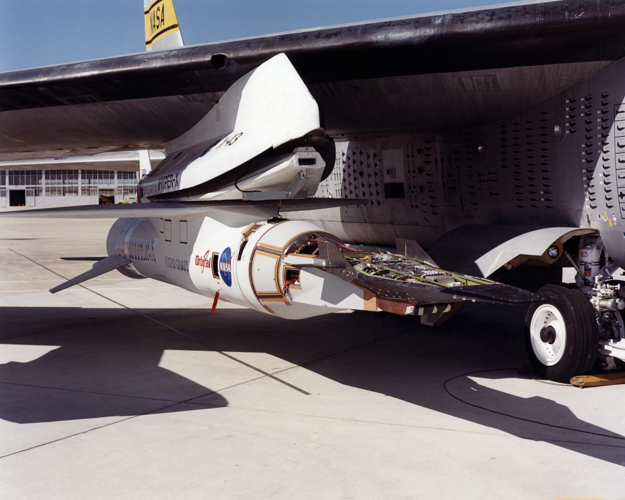
The first of three X-43A hypersonic research aircraft and its modified Pegasus® booster rocket recently underwent combined systems testing while mounted to NASA's NB-52B carrier aircraft at the Dryden Flight Research Center, Edwards, California. The combined systems test was one of the last major milestones in the Hyper-X research program before the first X-43A flight. One of the major goals of the Hyper-X program is flight validation of airframe-integrated, air-breathing propulsion system, which so far have only been tested in ground facilities, such as wind tunnels. The X-43A flights will be the first actual flight tests of an aircraft powered by a revolutionary supersonic-combustion ramjet ("scramjet") engine capable of operating at hypersonic speeds above Mach 5 (five times the speed of sound). The X-43A design uses the underbody of the aircraft to form critical elements of the engine. The forebody shape helps compress the intake airflow, while the aft section acts as a nozzle to direct thrust. The 12-foot, unpiloted research vehicle was developed and built by MicroCraft Inc., Tullahoma, Tenn., under NASA contract. The booster, built by Orbital Sciences Corp., Dulles, Va., will accelerate the X-43A after the X-43A/booster "stack" is air-launched from NASA's venerable NB-52 mothership. The X-43A will separate from the rocket at a predetermined altitude and speed and fly a pre-programmed trajectory, conducting aerodynamic and propulsion experiments until it descends into the Pacific Ocean. Three research flights are planned, two at Mach 7 and one at Mach 10.
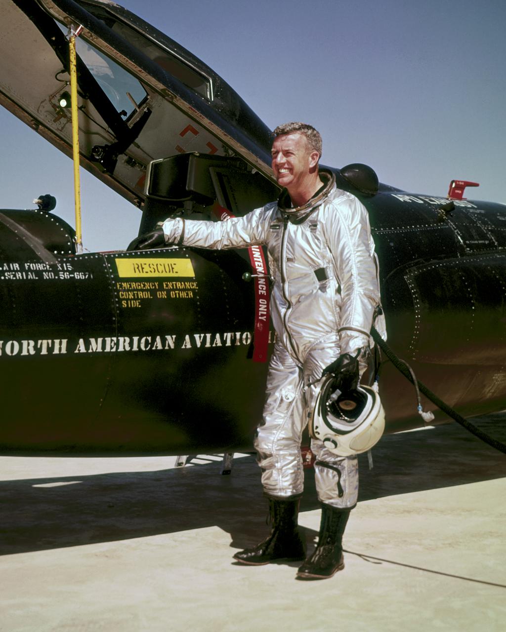
Joseph A. Walker was a Chief Research Pilot at the NASA Dryden Flight Research Center during the mid-1960s. He joined the NACA in March 1945, and served as project pilot at the Edwards flight research facility on such pioneering research projects as the D-558-1, D-558-2, X-1, X-3, X-4, X-5, and the X-15. He also flew programs involving the F-100, F-101, F-102, F-104, and the B-47. Walker made the first NASA X-15 flight on March 25, 1960. He flew the research aircraft 24 times and achieved its fastest speed and highest altitude. He attained a speed of 4,104 mph (Mach 5.92) during a flight on June 27, 1962, and reached an altitude of 354,300 feet on August 22, 1963 (his last X-15 flight). He was the first man to pilot the Lunar Landing Research Vehicle (LLRV) that was used to develop piloting and operational techniques for lunar landings. Walker was born February 20, 1921, in Washington, Pa. He lived there until graduating from Washington and Jefferson College in 1942, with a B.A. degree in Physics. During World War II he flew P-38 fighters for the Air Force, earning the Distinguished Flying Cross and the Air Medal with Seven Oak Clusters. Walker was the recipient of many awards during his 21 years as a research pilot. These include the 1961 Robert J. Collier Trophy, 1961 Harmon International Trophy for Aviators, the 1961 Kincheloe Award and 1961 Octave Chanute Award. He received an honorary Doctor of Aeronautical Sciences degree from his alma mater in June of 1962. Walker was named Pilot of the Year in 1963 by the National Pilots Association. He was a charter member of the Society of Experimental Test Pilots, and one of the first to be designated a Fellow. He was fatally injured on June 8, 1966, in a mid-air collision between an F-104 he was piloting and the XB-70.
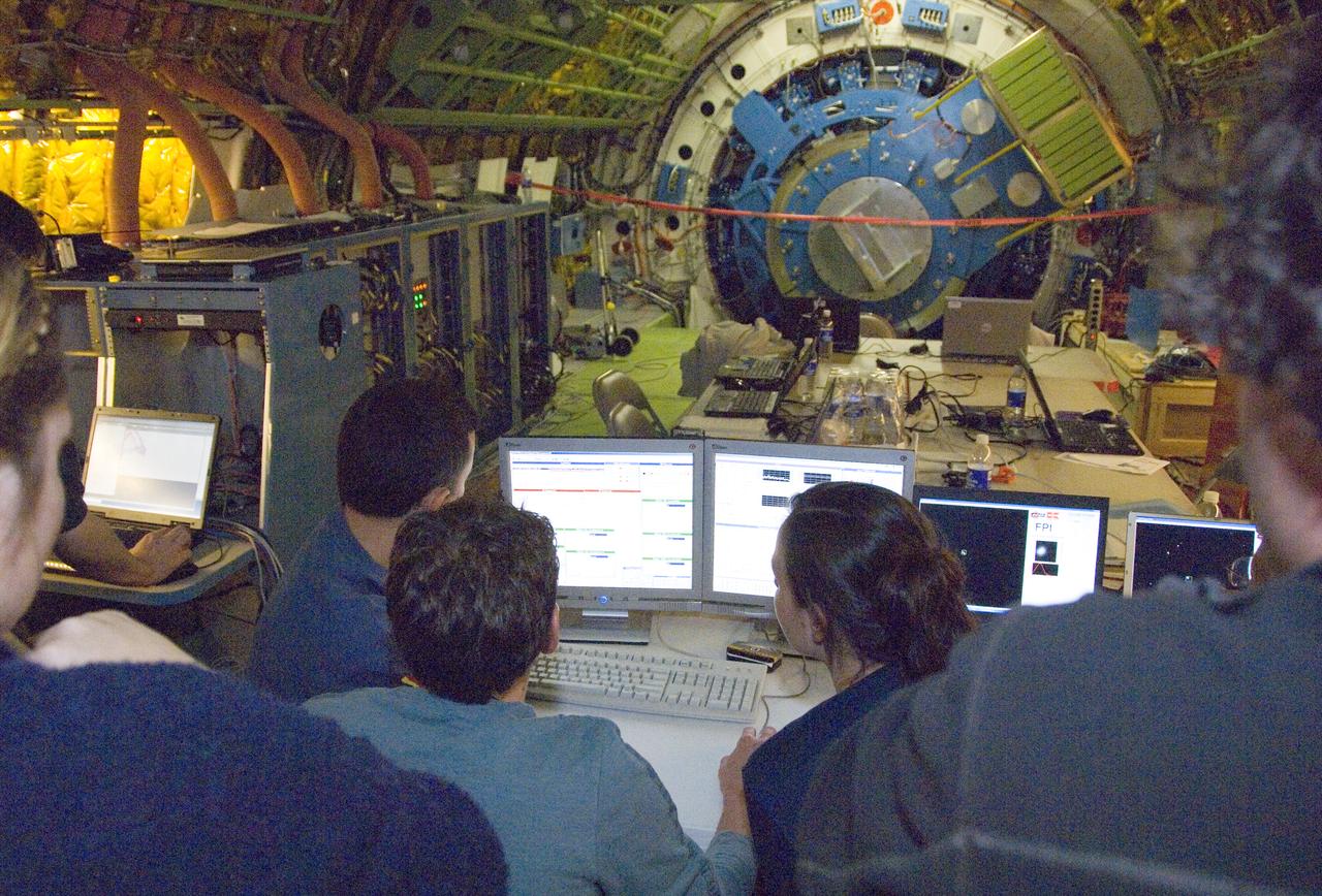
Scientists carefully examine data being received during nighttime line operations testing of the SOFIA airborne observatory's 2.5-meter infrared telescope.
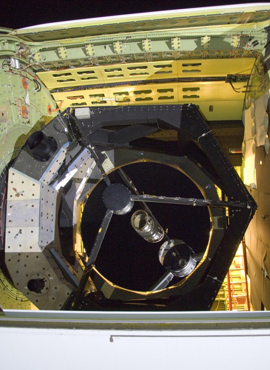
he SOFIA airborne observatory's 2.5-meter infrared telescope peers out from its cavity in the SOFIA rear fuselage during nighttime line operations testing.
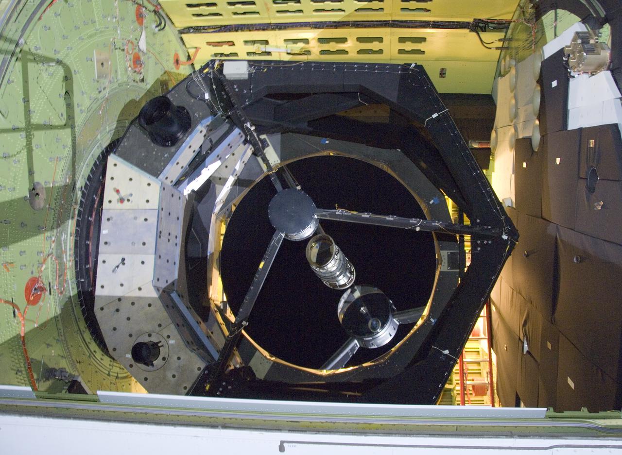
The 2.5-meter infrared telescope peers out from its cavity in the SOFIA airborne observatory during nighttime line operations testing at Palmdale, Calif.
The SOFIA airborne observatory's 2.5-meter infrared telescope peers out from its cavity in the SOFIA rear fuselage during nighttime line operations testing.
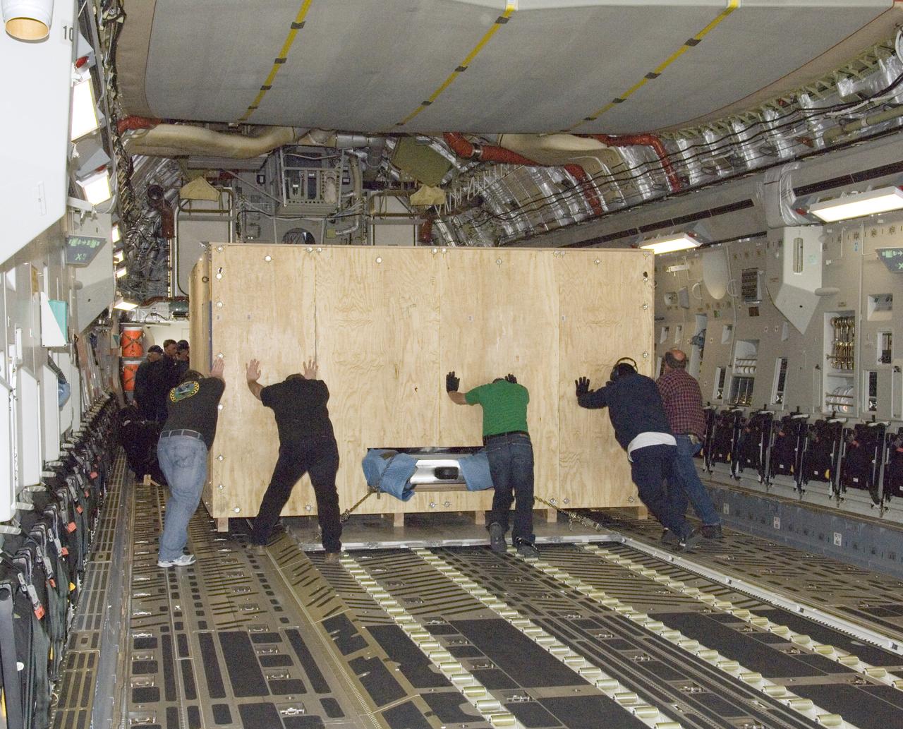
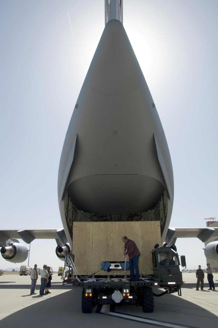
Technicians at NASA's Dryden Aircraft Operations Facility in Palmdale, Calif., loaded the German-built primary mirror assembly of the Stratospheric Observatory for Infrared Astronomy, or SOFIA, onto an Air Force C-17 for shipment to NASA's Ames Research Center on May 1, 2008. In preparation for the final finish coating of the mirror, the more than two-ton mirror assembly had been removed from its cavity in the rear fuselage of the highly modified SOFIA Boeing 747SP two weeks earlier. After arrival at NASA Ames at Moffett Field near Mountain View, Calif., the mirror would receive its aluminized finish coating before being re-installed in the SOFIA aircraft.
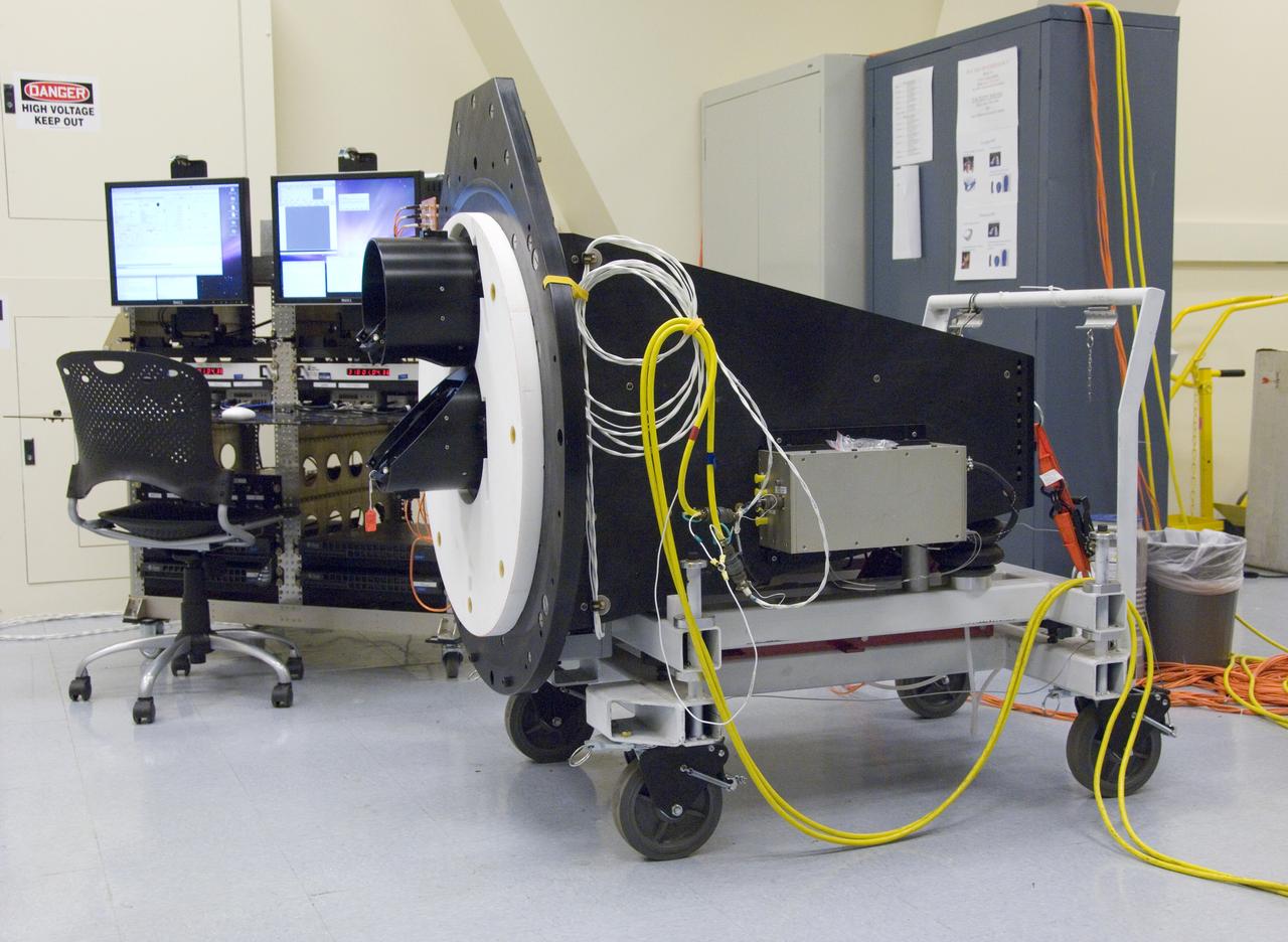
The Lowell Observatory's High-speed Imaging Photometer for Occultation rests on its dolly in the lab prior to installation on the SOFIA airborne observatory.
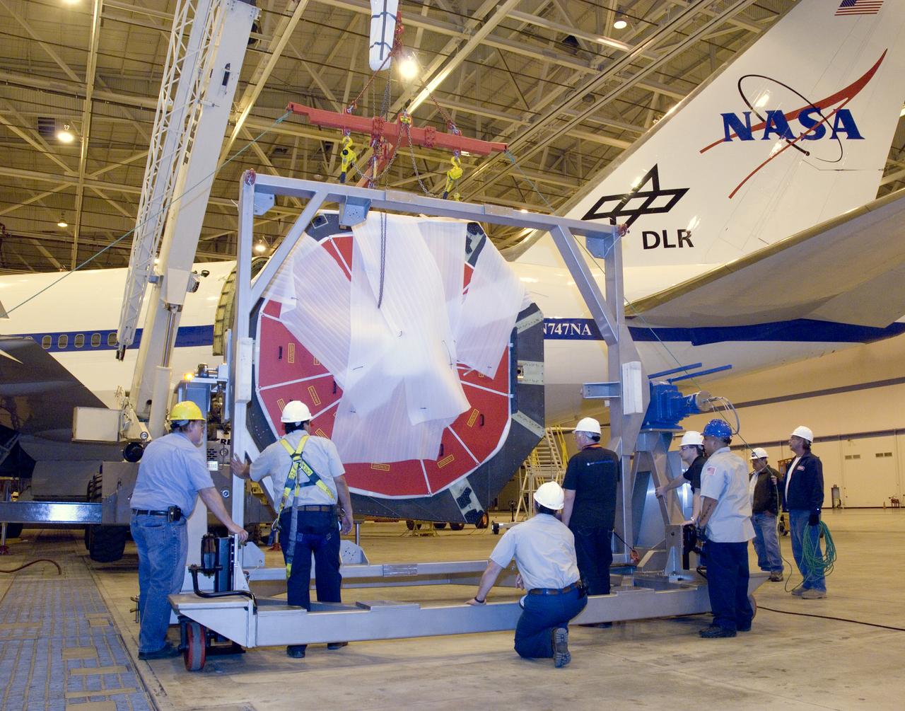
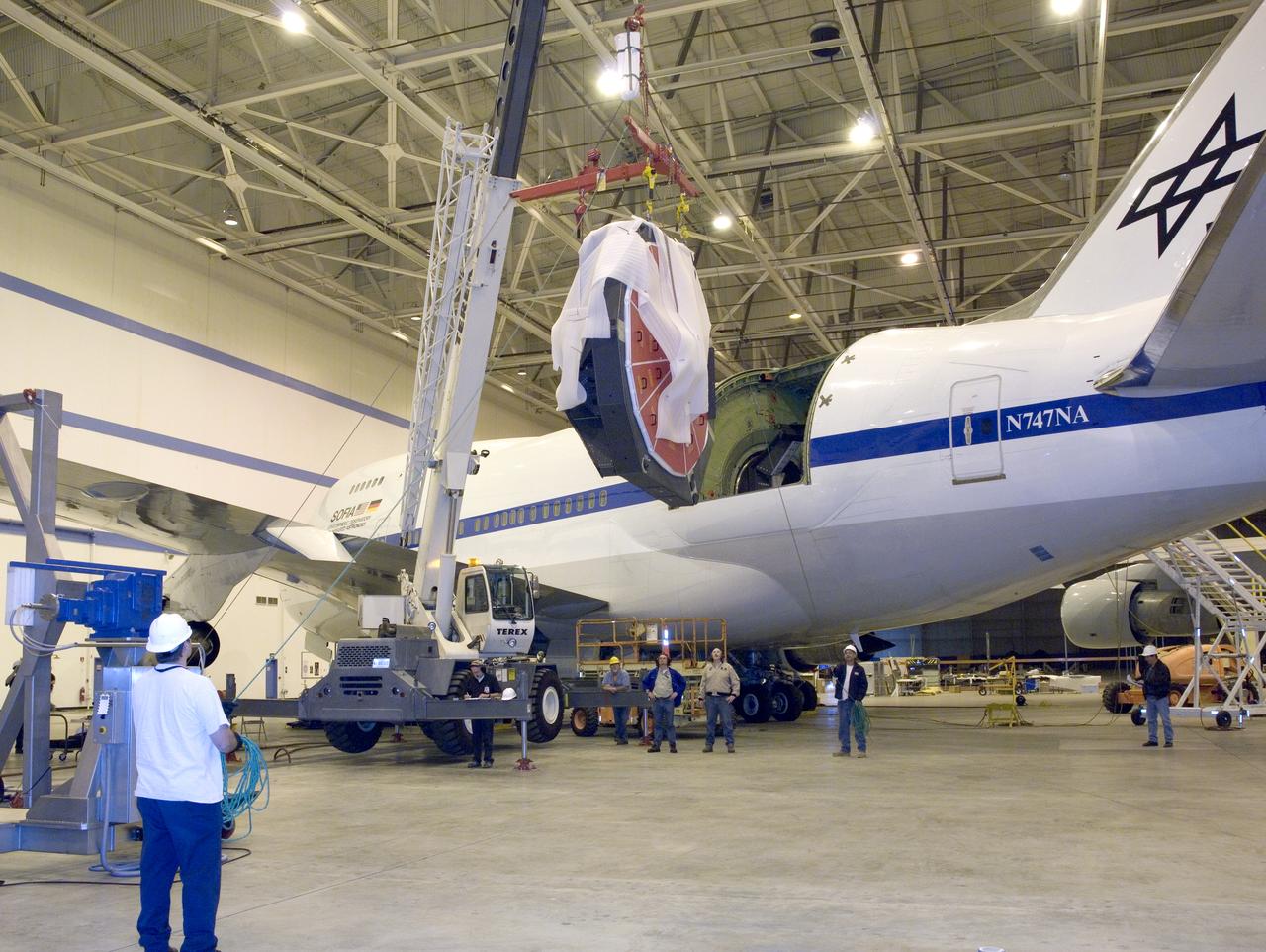
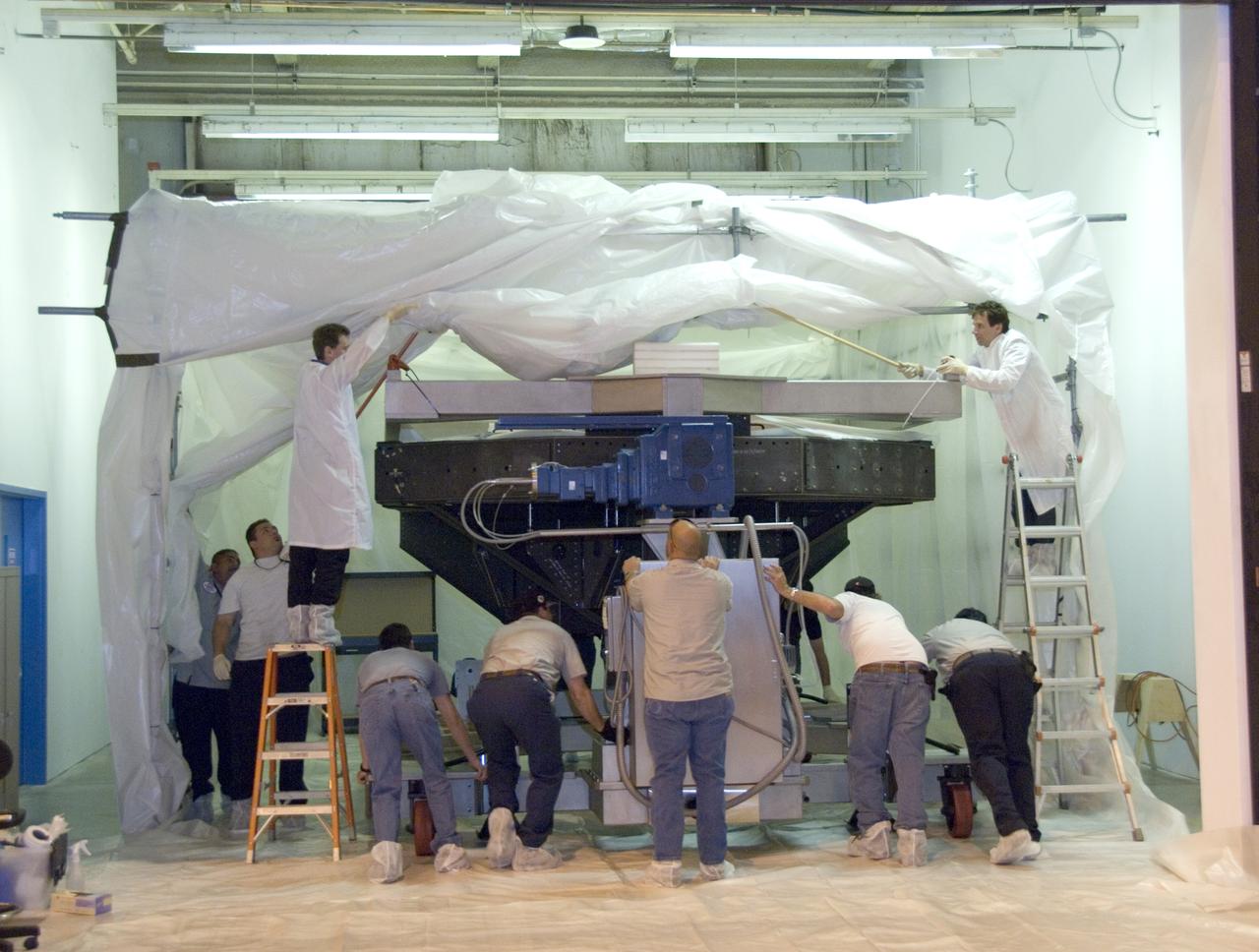
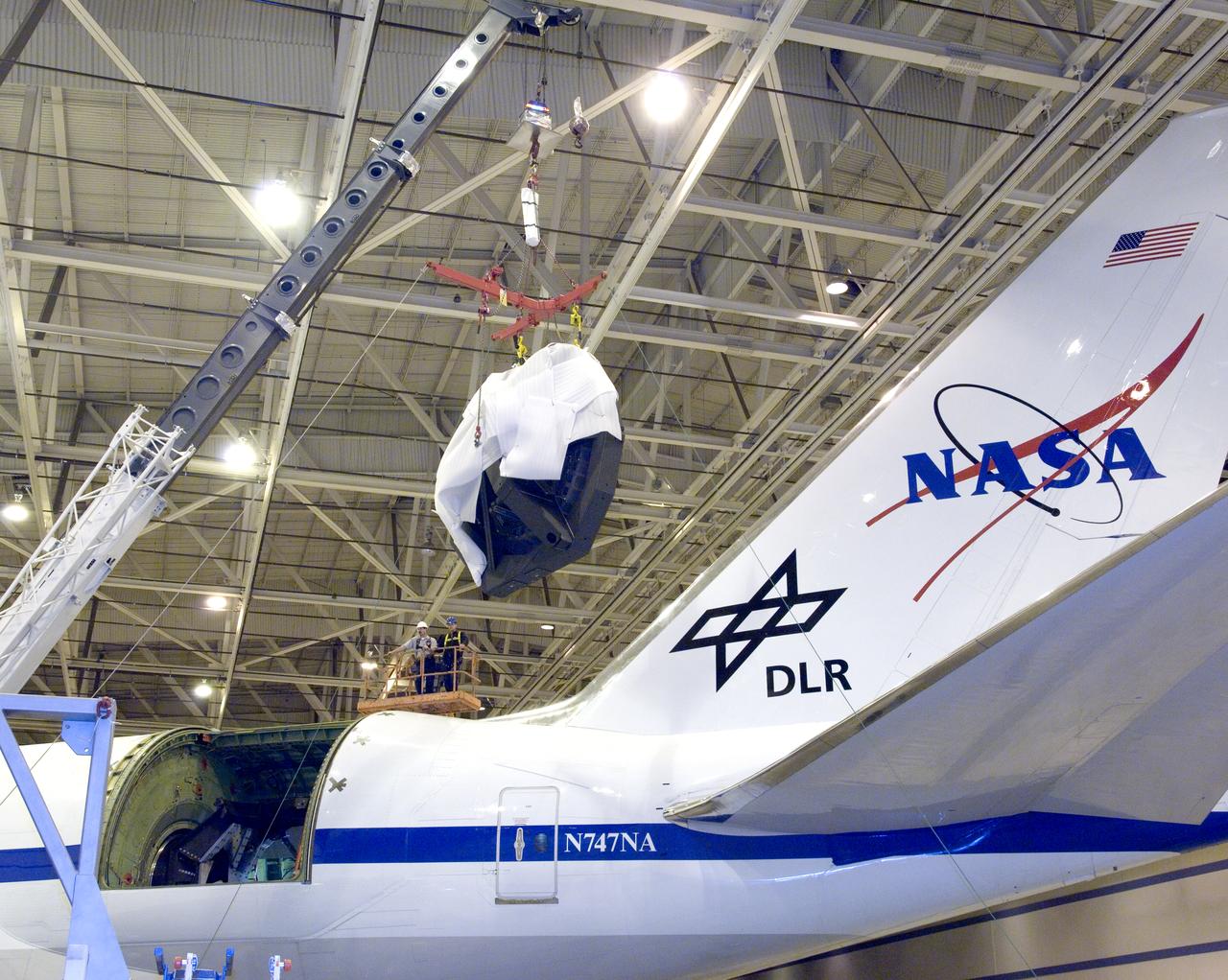
Technicians at the NASA Dryden Aircraft Operations Facility in Palmdale, Calif., removed the German-built primary mirror assembly from the Stratospheric Observatory for Infrared Astronomy, or SOFIA, April 18, 2008 in preparation for the final finish coating of the mirror. A precision crane lifted the more than two-ton mirror assembly from its cavity in the rear fuselage of the highly modified Boeing 747SP. The assembly was then secured in its transport dolly and moved to a clean room where it was prepared for shipment to NASA Ames Research Center at Moffett Field near Mountain View, Calif. where it would receive its aluminized finish coating before being re-installed in the SOFIA aircraft.
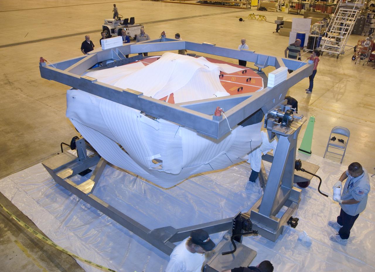
Technicians at the NASA Dryden Aircraft Operations Facility in Palmdale, Calif., removed the German-built primary mirror assembly from the Stratospheric Observatory for Infrared Astronomy, or SOFIA, April 18, 2008 in preparation for the final finish coating of the mirror. A precision crane lifted the more than two-ton mirror assembly from its cavity in the rear fuselage of the highly modified Boeing 747SP. The assembly was then secured in its transport dolly and moved to a clean room where it was prepared for shipment to NASA Ames Research Center at Moffett Field near Mountain View, Calif. where it would receive its aluminized finish coating before being re-installed in the SOFIA aircraft.
Technicians at the NASA Dryden Aircraft Operations Facility in Palmdale, Calif., removed the German-built primary mirror assembly from the Stratospheric Observatory for Infrared Astronomy, or SOFIA, April 18, 2008 in preparation for the final finish coating of the mirror. A precision crane lifted the more than two-ton mirror assembly from its cavity in the rear fuselage of the highly modified Boeing 747SP. The assembly was then secured in its transport dolly and moved to a clean room where it was prepared for shipment to NASA Ames Research Center at Moffett Field near Mountain View, Calif. where it would receive its aluminized finish coating before being re-installed in the SOFIA aircraft.
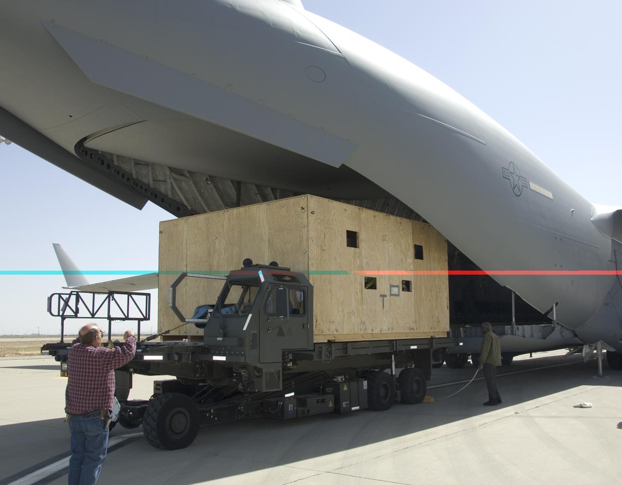
Technicians at NASA's Dryden Aircraft Operations Facility in Palmdale, Calif., loaded the German-built primary mirror assembly of the Stratospheric Observatory for Infrared Astronomy, or SOFIA, onto an Air Force C-17 for shipment to NASA's Ames Research Center on May 1, 2008. In preparation for the final finish coating of the mirror, the more than two-ton mirror assembly had been removed from its cavity in the rear fuselage of the highly modified SOFIA Boeing 747SP two weeks earlier. After arrival at NASA Ames at Moffett Field near Mountain View, Calif., the mirror would receive its aluminized finish coating before being re-installed in the SOFIA aircraft.
Technicians at NASA's Dryden Aircraft Operations Facility in Palmdale, Calif., loaded the German-built primary mirror assembly of the Stratospheric Observatory for Infrared Astronomy, or SOFIA, onto an Air Force C-17 for shipment to NASA's Ames Research Center on May 1, 2008. In preparation for the final finish coating of the mirror, the more than two-ton mirror assembly had been removed from its cavity in the rear fuselage of the highly modified SOFIA Boeing 747SP two weeks earlier. After arrival at NASA Ames at Moffett Field near Mountain View, Calif., the mirror would receive its aluminized finish coating before being re-installed in the SOFIA aircraft.
Technicians at the NASA Dryden Aircraft Operations Facility in Palmdale, Calif., removed the German-built primary mirror assembly from the Stratospheric Observatory for Infrared Astronomy, or SOFIA, April 18, 2008 in preparation for the final finish coating of the mirror. A precision crane lifted the more than two-ton mirror assembly from its cavity in the rear fuselage of the highly modified Boeing 747SP. The assembly was then secured in its transport dolly and moved to a clean room where it was prepared for shipment to NASA Ames Research Center at Moffett Field near Mountain View, Calif. where it would receive its aluminized finish coating before being re-installed in the SOFIA aircraft.
Technicians at the NASA Dryden Aircraft Operations Facility in Palmdale, Calif., removed the German-built primary mirror assembly from the Stratospheric Observatory for Infrared Astronomy, or SOFIA, April 18, 2008 in preparation for the final finish coating of the mirror. A precision crane lifted the more than two-ton mirror assembly from its cavity in the rear fuselage of the highly modified Boeing 747SP. The assembly was then secured in its transport dolly and moved to a clean room where it was prepared for shipment to NASA Ames Research Center at Moffett Field near Mountain View, Calif. where it would receive its aluminized finish coating before being re-installed in the SOFIA aircraft.