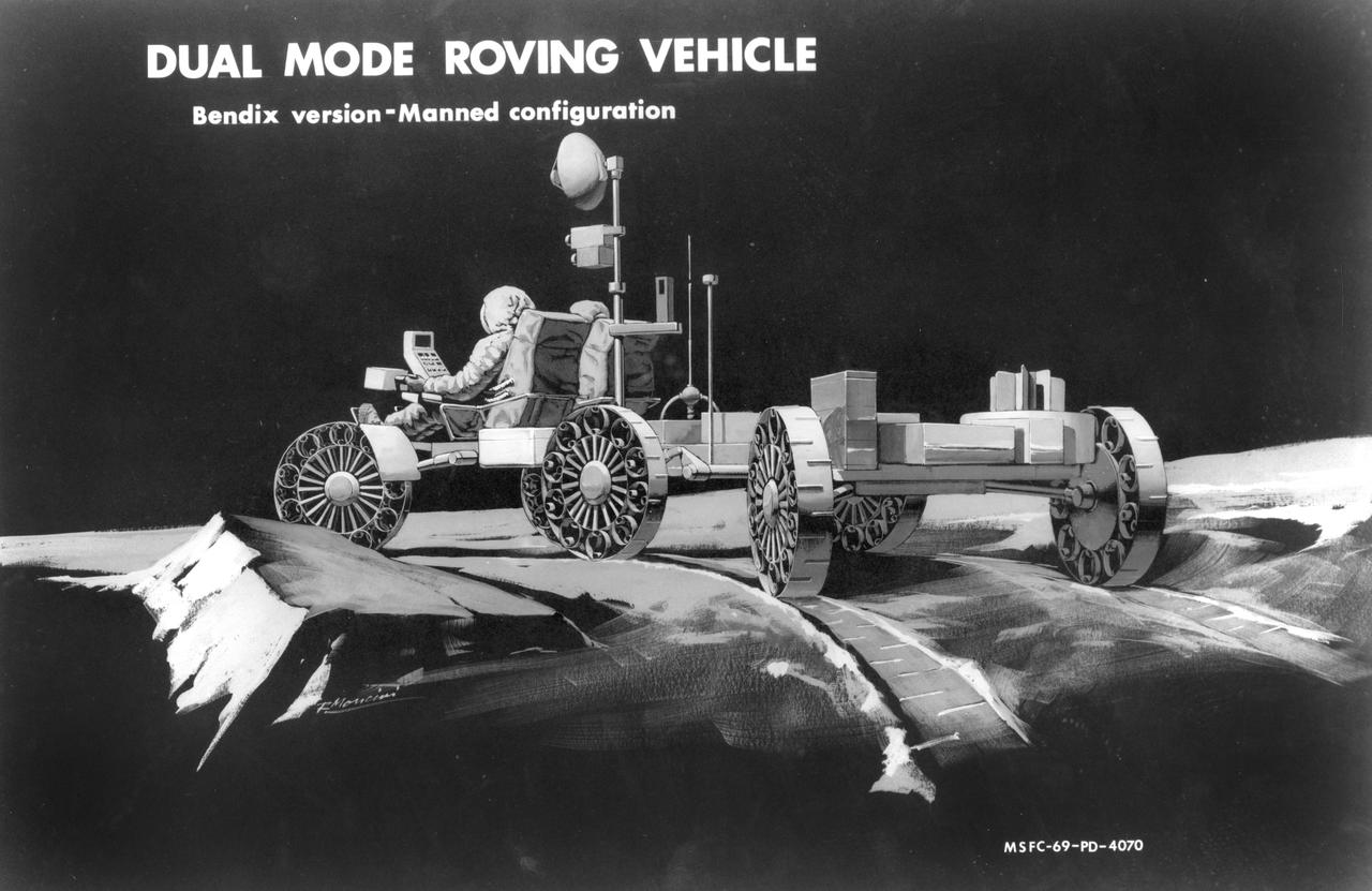
Artist’s concept of a dual mode Lunar Roving Vehicle (LRV) on the Lunar surface. This represents the Bendix version in an unmanned configuration. The LRV was developed under the direction of MSFC to allow Apollo astronauts a greater range of mobility during lunar exploration missions.
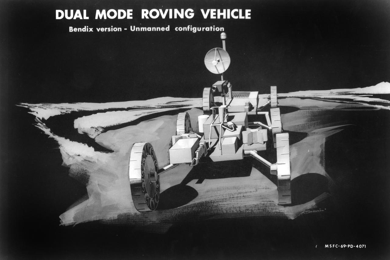
Artist’s concept of a dual mode Lunar Roving Vehicle (LRV) on the Lunar surface. This represents the Bendix version in an unmanned configuration. The LRV was developed under the direction of MSFC to allow Apollo astronauts a greater range of mobility during lunar exploration missions.

Artist’s concept of a dual mode Lunar Roving Vehicle (LRV) on the Lunar surface. This represents the Grumman version in an unmanned configuration. The LRV was developed under the direction of MSFC to allow Apollo astronauts a greater range of mobility during lunar exploration missions.
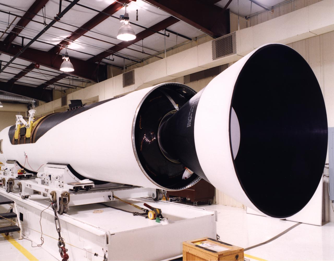
A close-up view of the front end of a Pegasus rocket booster being prepared by technicians at the Dryden Flight Research Center for flight tests with the X-43A "Hypersonic Experimental Vehicle," or "Hyper-X." The X-43A, which will be attached to the Pegasus booster and drop launched from NASA's B-52 mothership, was developed to research dual-mode ramjet/scramjet propulsion system at speeds from Mach 7 up to Mach 10 (7 to 10 times the speed of sound, which varies with temperature and altitude).
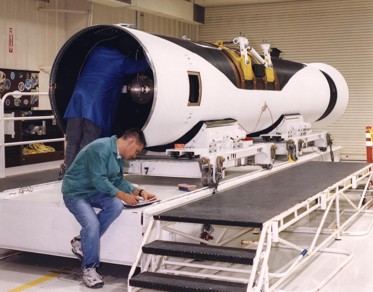
Technicians prepare a Pegasus rocket booster for flight tests with the X-43A "Hypersonic Experimental Vehicle," or "Hyper-X." The X-43A, which will be attached to the Pegasus booster and drop launched from NASA's B-52 mothership, was developed to research dual-mode ramjet/scramjet propulsion system at speeds from Mach 7 up to Mach 10 (7 to 10 times the speed of sound, which varies with temperature and altitude).
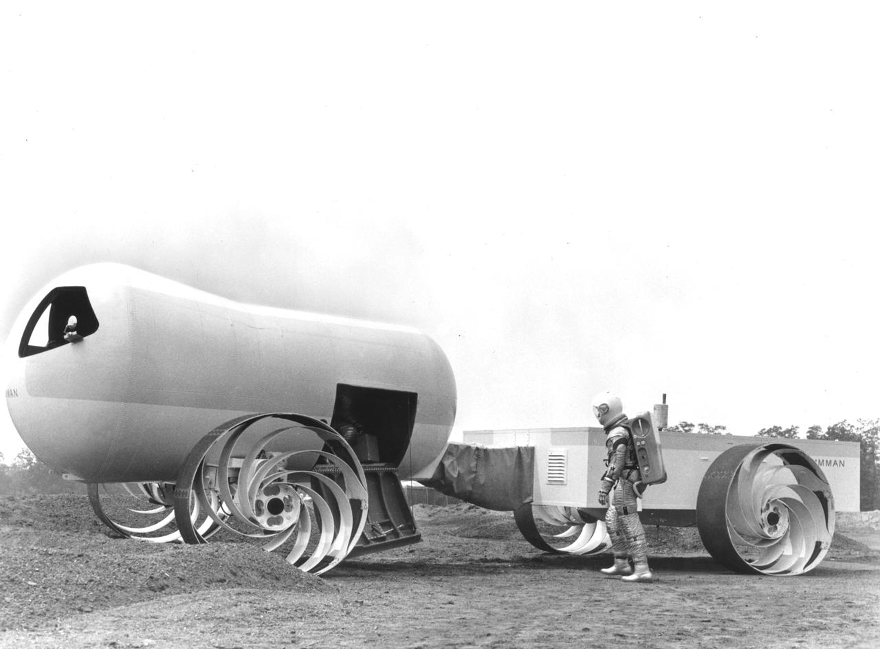
This Mobility Test Article (MTA) was a concept of a possible dual mode Lunar Roving Vehicle (LRV) built by the Grumman Industries for NASA’s Marshall Space Flight Center (MSFC). The data provided by the MTA helped in designing the Lunar Roving Vehicle (LRV), developed under the direction of MSFC. The LRV was designed to allow Apollo astronauts a greater range of mobility during lunar exploration missions.
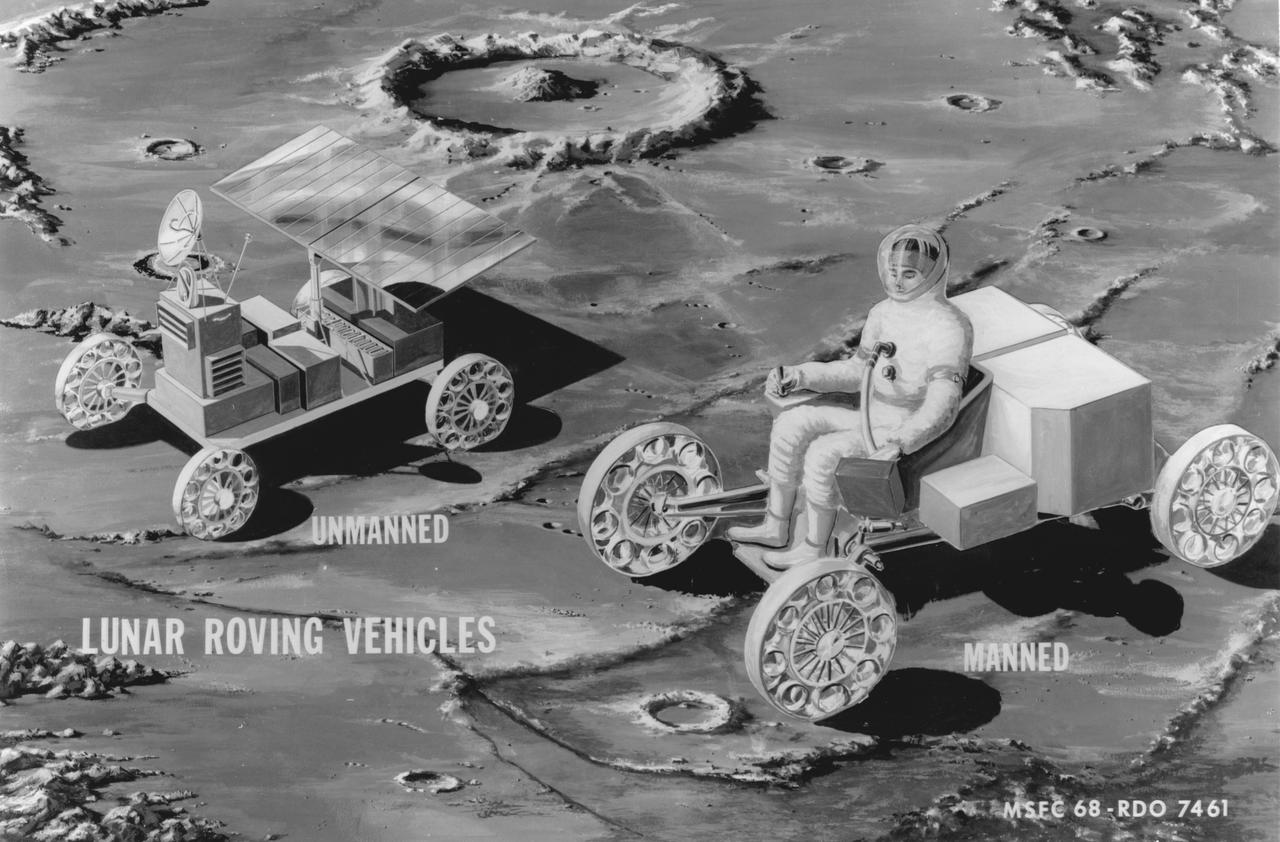
Artist’s manned and unmanned concepts of a Lunar Roving Vehicle (LRV) Mobility Test Article (MTA) on the Lunar surface. The data provided by the MTA helped in designing the LRV, developed under the direction of MSFC. The LRV was designed to allow Apollo astronauts a greater range of mobility during lunar exploration missions.
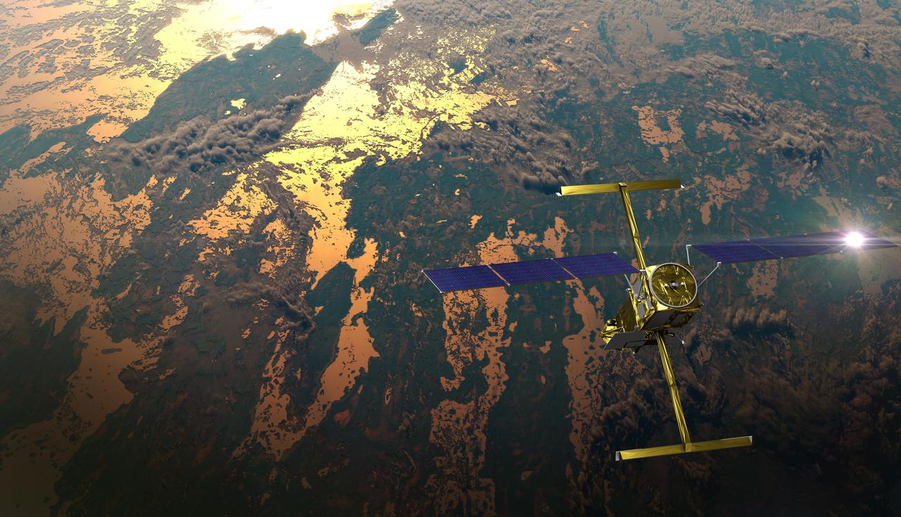
The international Surface Water and Ocean Topography (SWOT) satellite is shown in orbit over Earth in this illustration, with sunlight glinting off one of its solar arrays and both antennas of its Ka-band Radar Interferometer (KaRIn) instrument extended. The mission is a collaborative effort between NASA and the French space agency Centre National d'Études Spatiales (CNES) – with contributions from the Canadian Space Agency (CSA) and the UK Space Agency. KaRIn is the scientific heart of the SWOT satellite, which will survey the water on more than 90% of Earth's surface, measuring the height of water in lakes, rivers, reservoirs, and the ocean. To do that, KaRIn will transmit radar pulses to Earth's surface and use its two antennas to triangulate the return signals that bounce back. Mounted at the ends of a boom 33 feet (10 meters) long, the antennas will collect data along a swath 30 miles (50 kilometers) wide on either side of the satellite. KaRIn will operate in two modes: A lower-resolution mode over the ocean will involve significant onboard processing of the data to reduce the volume of information sent during downlinks to Earth; a higher-resolution mode will be used mainly over land. Scheduled to launch from Vandenberg Space Force Base in Central California on Dec. 15, 2022, SWOT is being jointly developed by NASA and CNES, with contributions from the CSA and the UK Space Agency. NASA's Jet Propulsion Laboratory, which is managed for the agency by Caltech in Pasadena, California, leads the U.S. component of the project. For the flight system payload, NASA is providing the Ka-band Radar Interferometer (KaRIn) instrument, a GPS science receiver, a laser retroreflector, a two-beam microwave radiometer, and NASA instrument operations. CNES is providing the Doppler Orbitography and Radioposition Integrated by Satellite (DORIS) system, the dual frequency Poseidon altimeter (developed by Thales Alenia Space), the KaRIn radio-frequency subsystem (together with Thales Alenia Space and with support from the UK Space Agency), the satellite platform, and ground control segment. CSA is providing the KaRIn high-power transmitter assembly. NASA is providing the launch vehicle and associated launch services. https://photojournal.jpl.nasa.gov/catalog/PIA25595
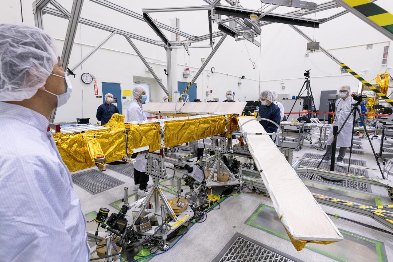
Members of the international Surface Water and Ocean Topography (SWOT) mission test one of the antennas for the Ka-band Radar Interferometer (KaRIn) instrument in a clean room at NASA's Jet Propulsion Laboratory in Southern California. The mission is a collaborative effort between NASA and the French space agency Centre National d'Études Spatiales (CNES) – with contributions from the Canadian Space Agency (CSA) and the UK Space Agency. KaRIn is the scientific heart of the SWOT satellite, which will survey the water on more than 90% of Earth's surface, measuring the height of water in lakes, rivers, reservoirs, and the ocean. To do that, KaRIn will transmit radar pulses to Earth's surface and use its two antennas to triangulate the return signals that bounce back. Mounted at the ends of a boom 33 feet (10 meters) long, the antennas will collect data along a swath 30 miles (50 kilometers) wide on either side of the satellite. KaRIn will operate in two modes: A lower-resolution mode over the ocean will involve significant onboard processing of the data to reduce the volume of information sent during downlinks to Earth; a higher-resolution mode will be used mainly over land. Scheduled to launch from Vandenberg Space Force Base in Central California on Dec. 15, 2022, SWOT is being jointly developed by NASA and CNES, with contributions from the CSA and the UK Space Agency. NASA's Jet Propulsion Laboratory, which is managed for the agency by Caltech in Pasadena, California, leads the U.S. component of the project. For the flight system payload, NASA is providing the Ka-band Radar Interferometer (KaRIn) instrument, a GPS science receiver, a laser retroreflector, a two-beam microwave radiometer, and NASA instrument operations. CNES is providing the Doppler Orbitography and Radioposition Integrated by Satellite (DORIS) system, the dual frequency Poseidon altimeter (developed by Thales Alenia Space), the KaRIn radio-frequency subsystem (together with Thales Alenia Space and with support from the UK Space Agency), the satellite platform, and ground control segment. CSA is providing the KaRIn high-power transmitter assembly. NASA is providing the launch vehicle and associated launch services. https://photojournal.jpl.nasa.gov/catalog/PIA25594
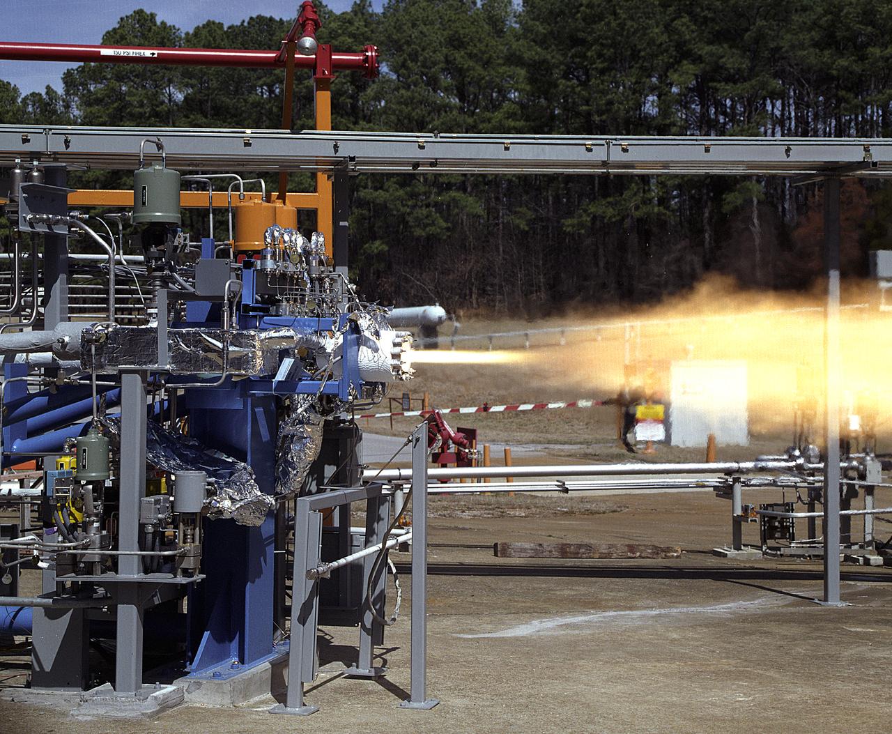
NASA's Marshall Space Flight Center (MSFC) in Huntsville, Alabama, has begun a series of engine tests on the Reaction Control Engine developed by TRW Space and Electronics for NASA's Space Launch Initiative (SLI). SLI is a technology development effort aimed at improving the safety, reliability, and cost effectiveness of space travel for reusable launch vehicles. The engine in this photo, the first engine tested at MSFC that includes SLI technology, was tested for two seconds at a chamber pressure of 185 pounds per square inch absolute (psia). Propellants used were liquid oxygen as an oxidizer and liquid hydrogen as fuel. Designed to maneuver vehicles in orbit, the engine is used as an auxiliary propulsion system for docking, reentry, fine-pointing, and orbit transfer while the vehicle is in orbit. The Reaction Control Engine has two unique features. It uses nontoxic chemicals as propellants, which creates a safer environment with less maintenance and quicker turnaround time between missions, and it operates in dual thrust modes, combining two engine functions into one engine. The engine operates at both 25 and 1,000 pounds of force, reducing overall propulsion weight and allowing vehicles to easily maneuver in space. The force of low level thrust allows the vehicle to fine-point maneuver and dock, while the force of the high level thrust is used for reentry, orbital transfer, and course positioning.
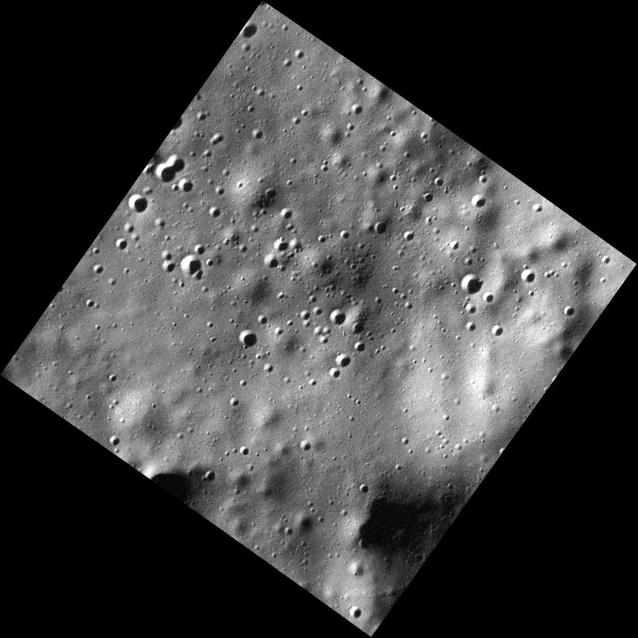
This image is one of the highest-resolution MDIS observations to date! Many craters of varying degradation states are visible, as well as gentle terrain undulations. Very short exposure times are needed to make these low-altitude observations while the spacecraft is moving quickly over the surface; thus the images are slightly noisier than typical MDIS images. This image was acquired as a high-resolution targeted observation. Targeted observations are images of a small area on Mercury's surface at resolutions much higher than the 200-meter/pixel morphology base map. It is not possible to cover all of Mercury's surface at this high resolution, but typically several areas of high scientific interest are imaged in this mode each week. Date acquired: March 15, 2014 Image Mission Elapsed Time (MET): 37173522 Image ID: 5936740 Instrument: Narrow Angle Camera (NAC) of the Mercury Dual Imaging System (MDIS) Center Latitude: 71.91° Center Longitude: 232.7° E Resolution: 5 meters/pixel Scale: The image is approximately 8.3 km (5.2 mi.) across. Incidence Angle: 79.4° Emission Angle: 4.0° Phase Angle: 83.4° http://photojournal.jpl.nasa.gov/catalog/PIA18370
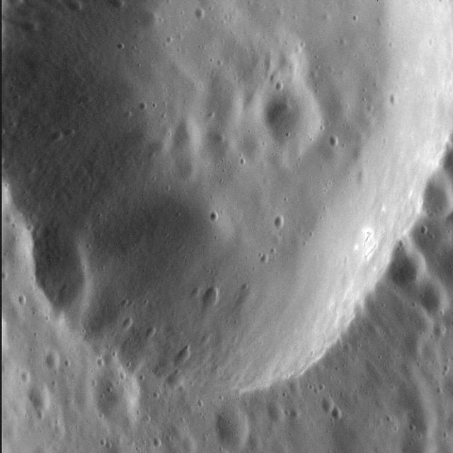
As MESSENGER passes progressively closer to Mercury, we see ever more resolved features in the images the spacecraft returns. Here, at a pixel scale of 9 meters, we see the eastern portion of an unnamed crater 13 km (8 mi.) in diameter. The wall of the crater is replete with smaller, superposed craters, some of which appear elongate possibly because they impacted on the larger crater's inclined wall. Interestingly, there are bright spots on the sunlight portion of this crater's wall -- which is where we might expect hollows to form. This image was acquired as a high-resolution targeted observation. Targeted observations are images of a small area on Mercury's surface at resolutions much higher than the 200-meter/pixel morphology base map. It is not possible to cover all of Mercury's surface at this high resolution, but typically several areas of high scientific interest are imaged in this mode each week. Date acquired: March 3, 2014 Image Mission Elapsed Time (MET): 36136338 Image ID: 5862963 Instrument: Narrow Angle Camera (NAC) of the Mercury Dual Imaging System (MDIS) Center Latitude: 56.3° Center Longitude: 301.6° E Resolution: 9 meters/pixel Scale: The field of view in this image is 11 km (7 mi.) across Incidence Angle: 59.3° Emission Angle: 43.0° Phase Angle: 102.3° North is to the right in this scene. http://photojournal.jpl.nasa.gov/catalog/PIA18372
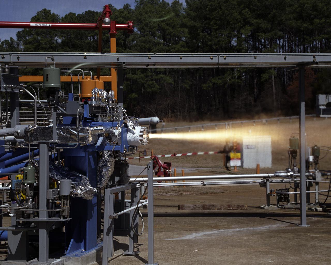
Engineers at the Marshall Space Flight Center (MSFC) have begun a series of engine tests on a new breed of space propulsion: a Reaction Control Engine developed for the Space Launch Initiative (SLI). The engine, developed by TRW Space and Electronics of Redondo Beach, California, is an auxiliary propulsion engine designed to maneuver vehicles in orbit. It is used for docking, reentry, attitude control, and fine-pointing while the vehicle is in orbit. The engine uses nontoxic chemicals as propellants, a feature that creates a safer environment for ground operators, lowers cost, and increases efficiency with less maintenance and quicker turnaround time between missions. Testing includes 30 hot-firings. This photograph shows the first engine test performed at MSFC that includes SLI technology. Another unique feature of the Reaction Control Engine is that it operates at dual thrust modes, combining two engine functions into one engine. The engine operates at both 25 and 1,000 pounds of force, reducing overall propulsion weight and allowing vehicles to easily maneuver in space. The low-level thrust of 25 pounds of force allows the vehicle to fine-point maneuver and dock while the high-level thrust of 1,000 pounds of force is used for reentry, orbit transfer, and coarse positioning. SLI is a NASA-wide research and development program, managed by the MSFC, designed to improve safety, reliability, and cost effectiveness of space travel for second generation reusable launch vehicles.