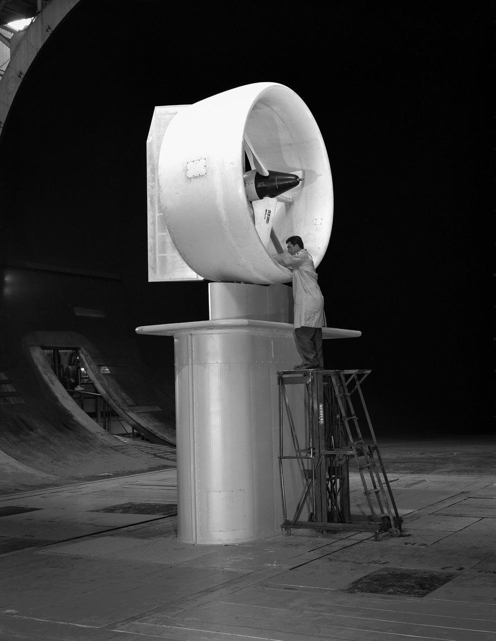
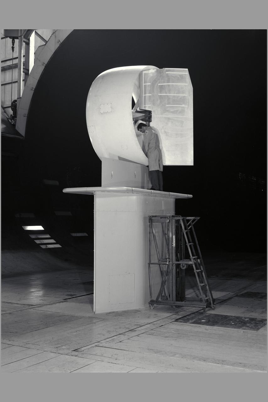
Tandem dual ducted fan mounted on ground plane on varriable height struts, 3/4 front view
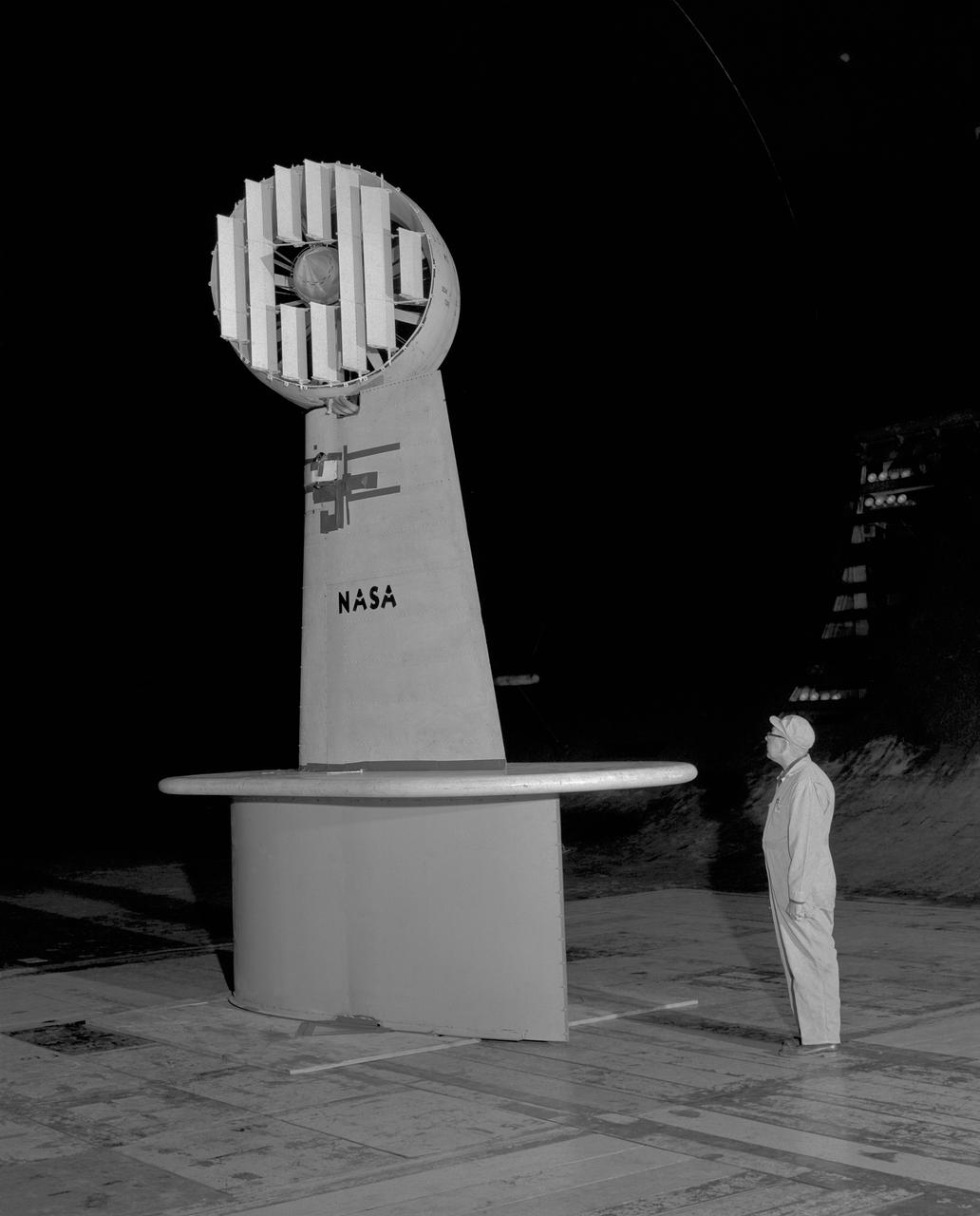
Wind Tunnel investigation of ducted fan though 180 deg angle of attack. 3/4 front view of Doak ducted fan, semi-span model with tufts.
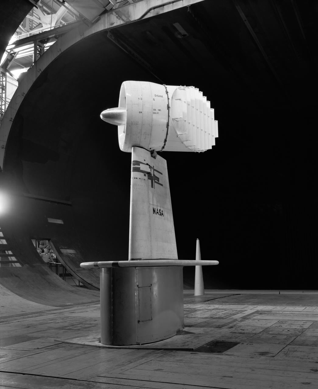
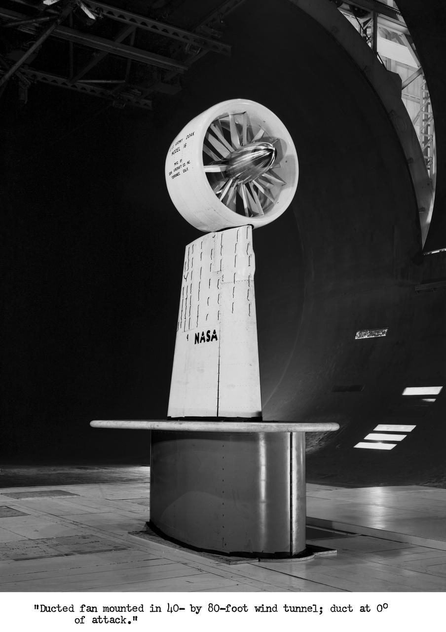
3/4 front view of Ducted fan model with 40 deg. exit vane cascade, semi span model.
3/4 rear view of ducted fan model with cascade exit vane in Ames 40x80 foot wind tunnel, with Tom Seymore, mechanic for Ames.
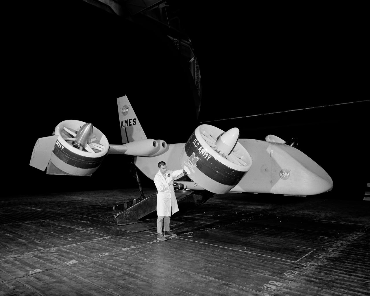
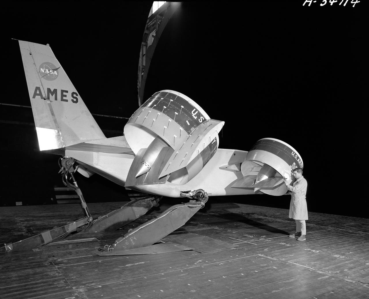
Bell X-22A full scale, Model-C ducted fan with semi-span mount. Duct at 90 degrees with Chuck Greco.
Stennis Space Center engineers are preparing to conduct water tests on an updated version of the scissors duct component of the J-2X engine. Measuring about 2 feet long and about 8 inches in diameter, the duct on the J-2X predecessor, the J-2, connected its fuel turbo pumps to the flight vehicle's upper stage run tanks. According to NASA's J-2X project manager at SSC, Gary Benton, the water tests should establish the limits of the duct's ability to withstand vibration.
Tandem dual ducted fan mounted on ground plate. 3/4 rear view. Testing for recirculation decrease in performance of lift fans varies with ground effect.
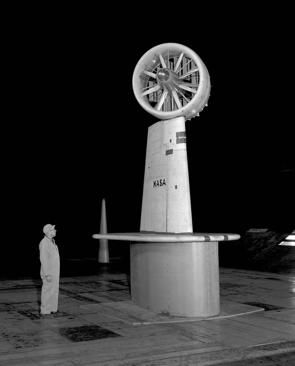
3/4 front view with cascade exit vane in Ames 40x80 foot wind tunnel, with Tom Seymore, mechanic for Ames.
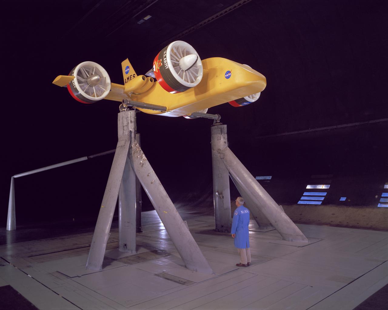
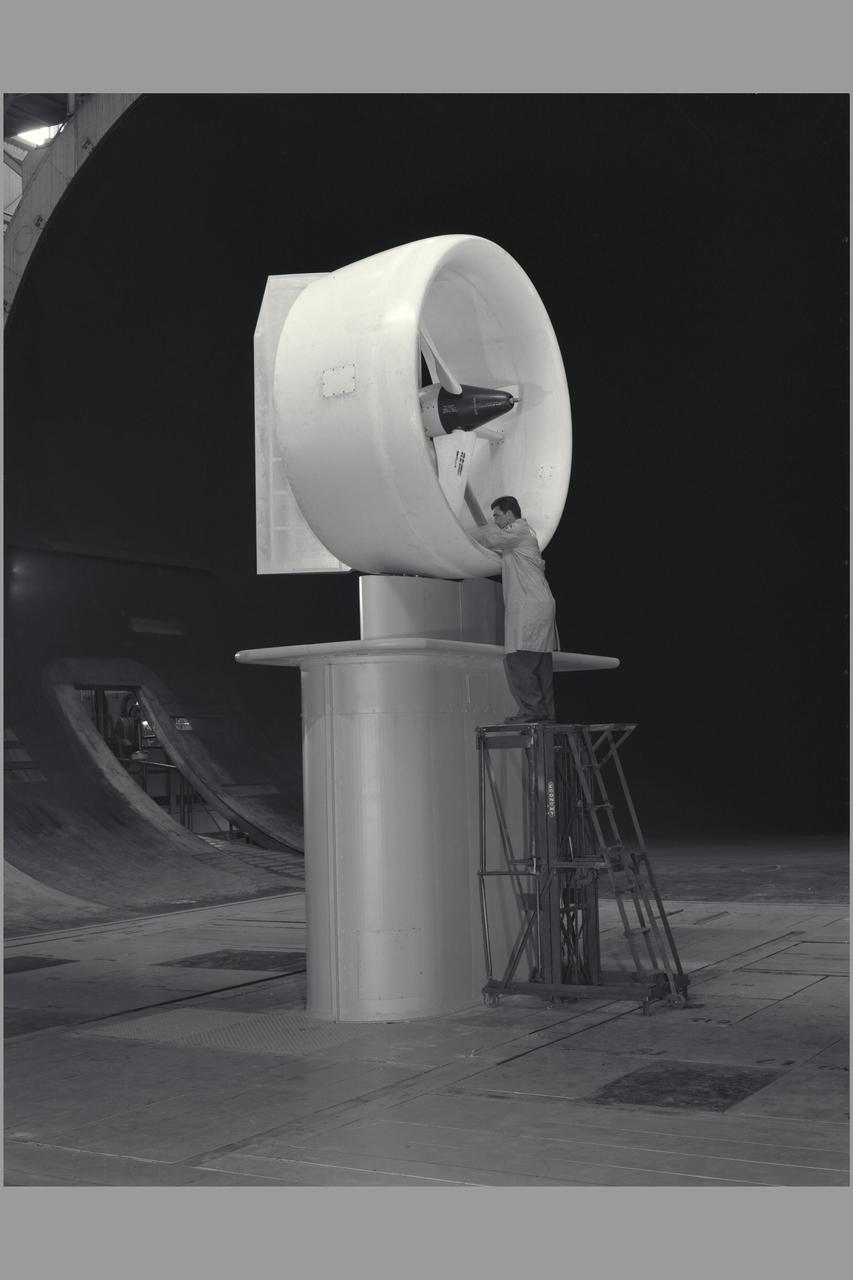
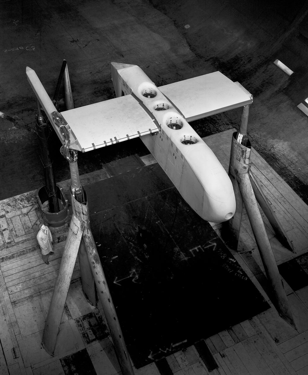
3/4 front view from below, showing Pods and Fan Rotating. March A. Zeiger standing in front. Tandem Dual Ducted Fan V/STOL Model in Ames 40x80 foot Wind Tunnel

Significant ice build-up on the Simulated Inter-compressor Duct Research Model (SIDRM) at the Icing Research Tunnel. Photo Credit: (NASA/Jordan Salkin)
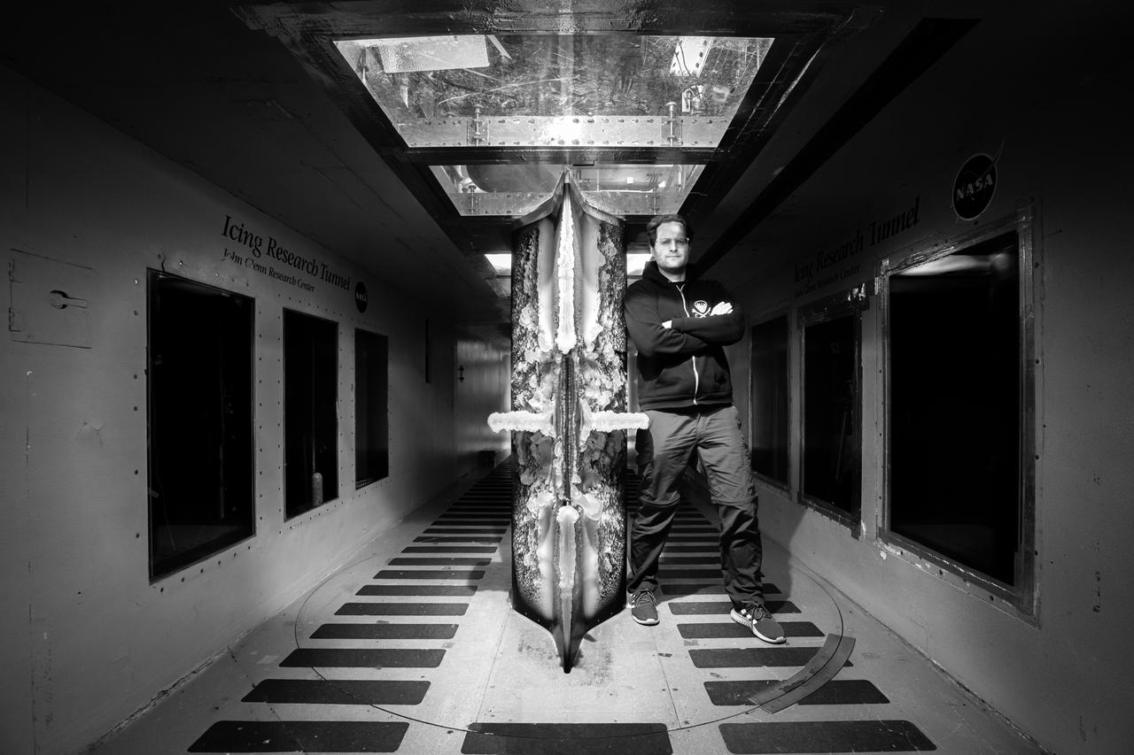
Lead researcher Tadas Bartkus poses after a run of his test with significant ice build-up on the Simulated Inter-compressor Duct Research Model (SIDRM) at the Icing Research Tunnel. Photo Credit: (NASA/Jordan Salkin)
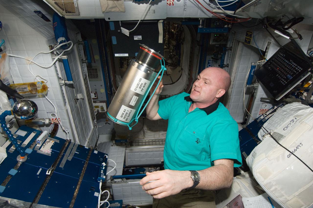
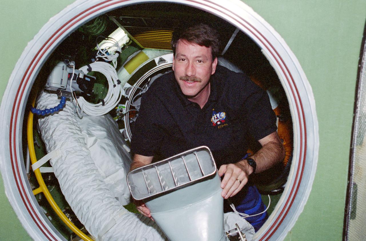
ISS030-E-272061 (17 April 2012) --- European Space Agency astronaut Andre Kuipers, Expedition 30 flight engineer, holds an Intermodular Ventilation (IMV) Supply Duct Jumper in the Harmony node of the International Space Station.
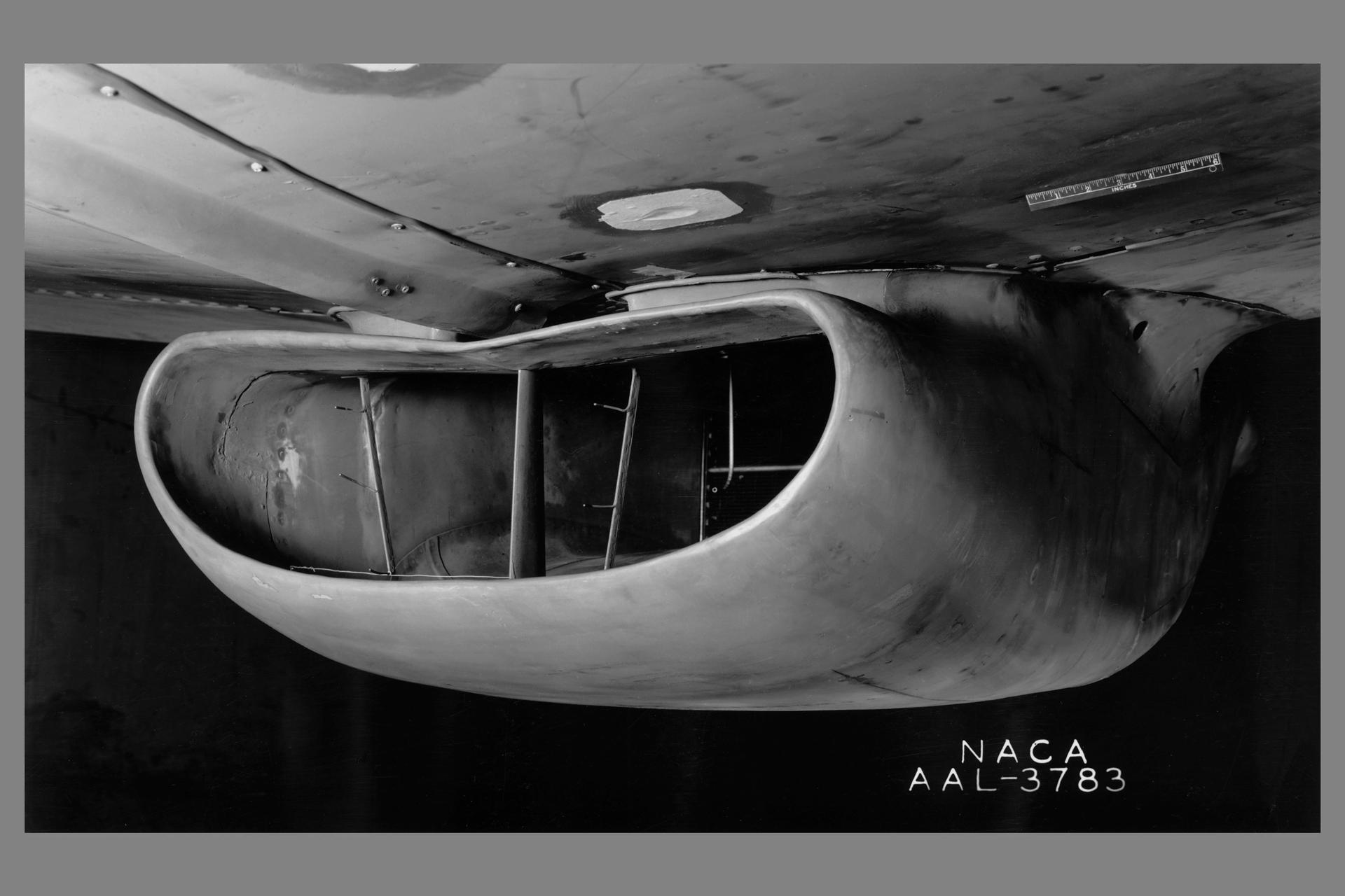
A portion of the North American P-51B airplane was tested in the 16-foot wind tunnel to devise a means of eliminating a rumble which occurred in the radiator duct system. The actual fuselage and center portion of the airplane was installed in the tunnel for this purpose as is shown. A change in the form of the duct was made and tested, which eliminated the rumble. The entrance to the original radiator duct is indicated in this photograph, and the revised form of the duct entrance in photographer AAL-3926.
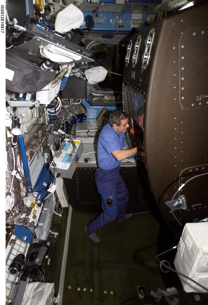
ISS012-E-10817 (9 December 2005) --- Astronaut William S. (Bill) McArthur Jr., Expedition 12 commander and NASA space station science officer, opens the back panel of the Crew Health Care System (CHeCS) rack and removes the Avionics Air Assembly (AAA) air ducts during in-flight maintenance (IFM) in the Destiny laboratory of the International Space Station.
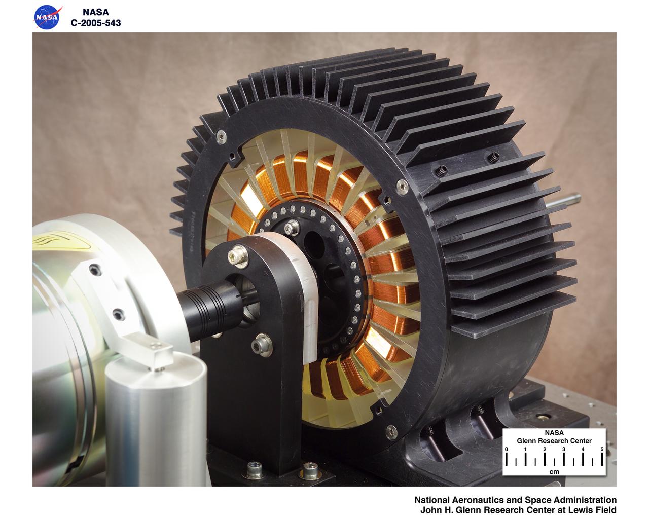
Levitated Ducted Fan (LDF) in the lab
LEVITATED DUCTED FAN TEST ROTOR
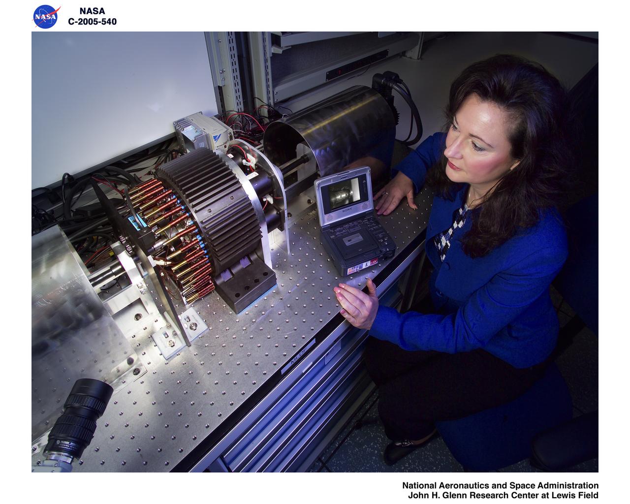
Levitated Ducted Fan (LDF) in the lab
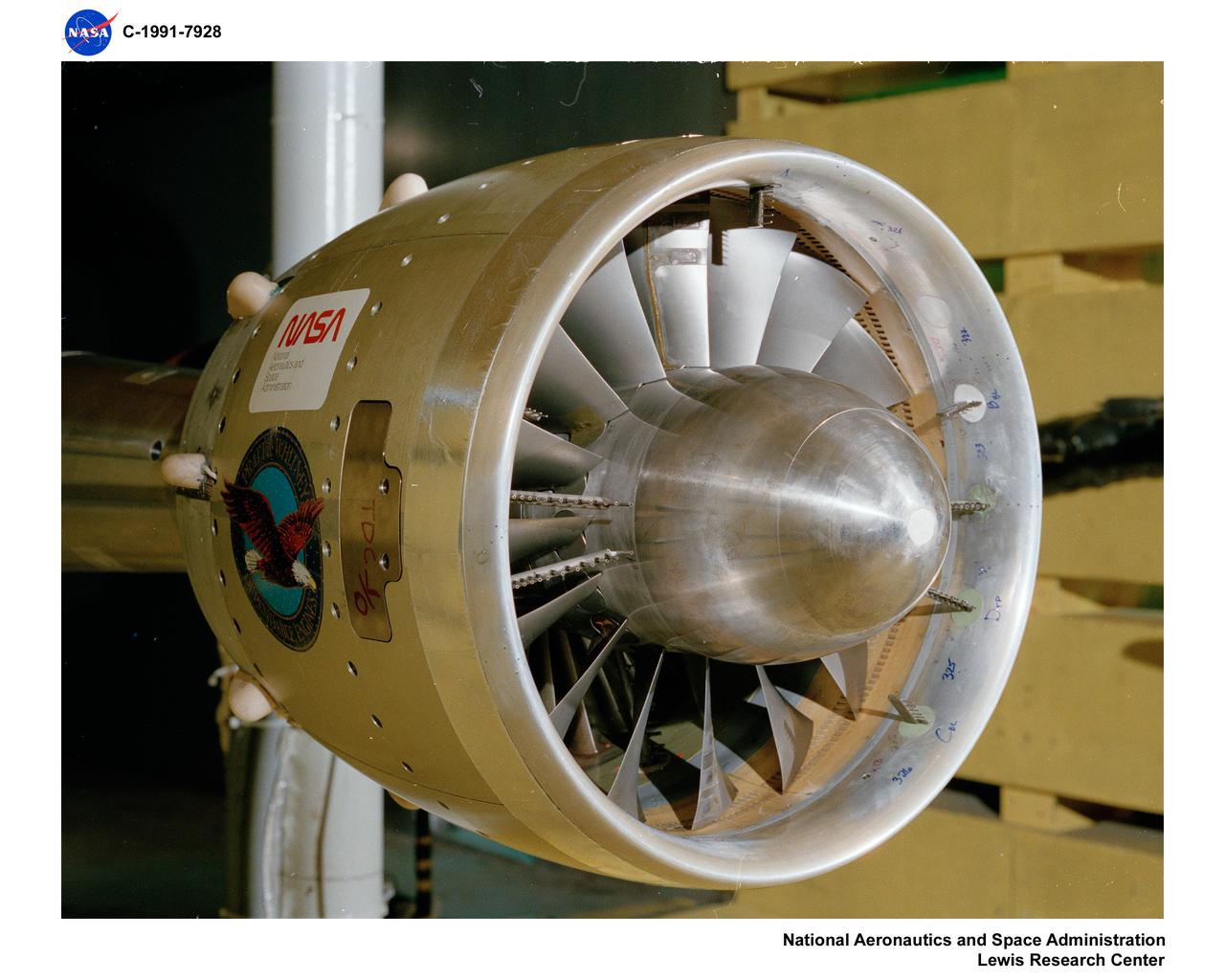
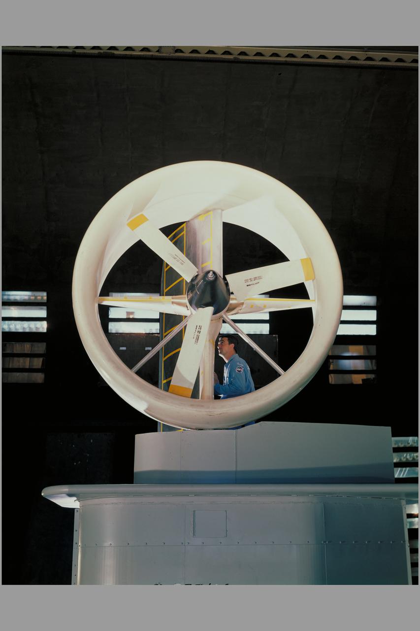
9X15 ADVANCED DUCTED PROPELLER MODEL
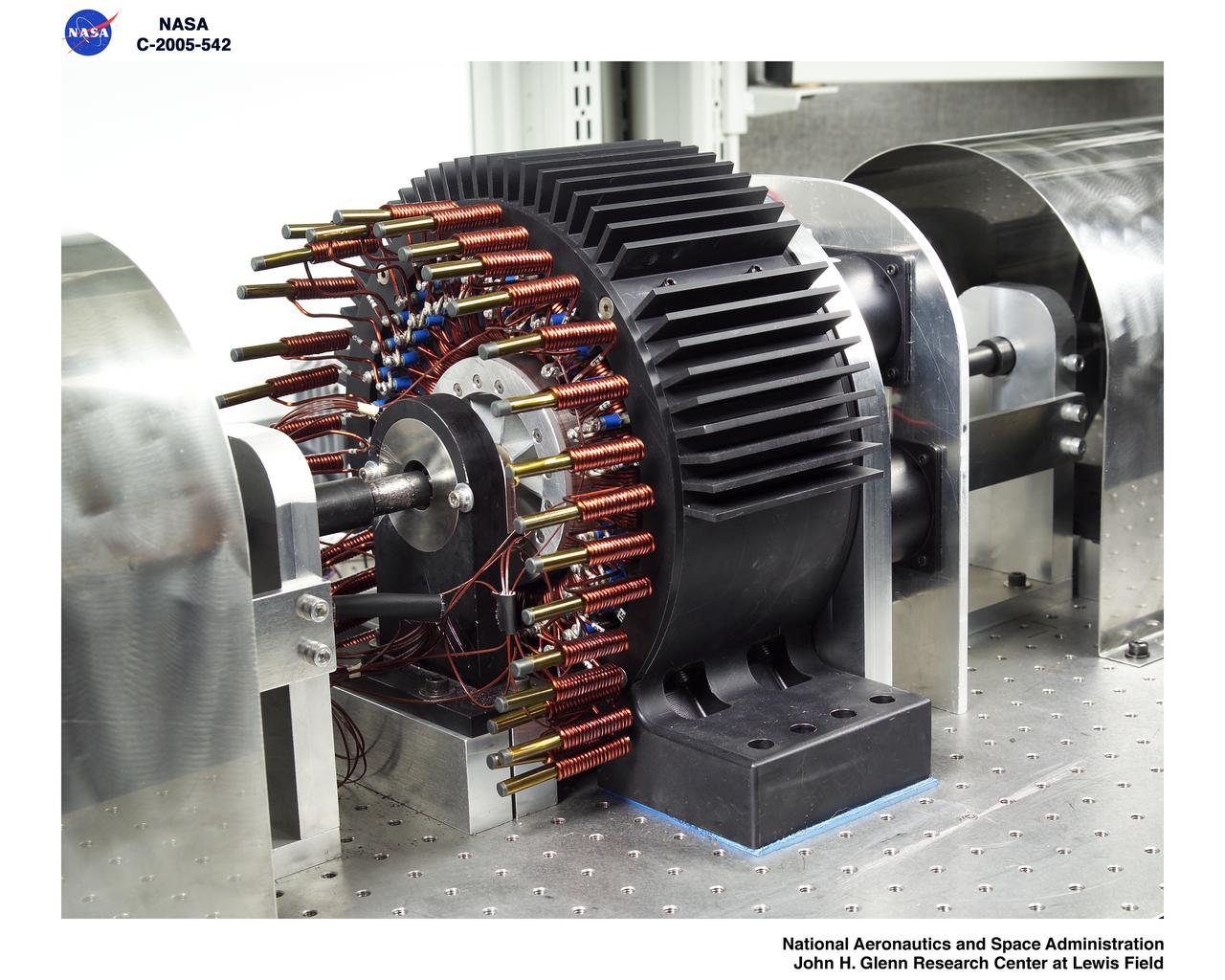
Levitated Ducted Fan (LDF) in the lab
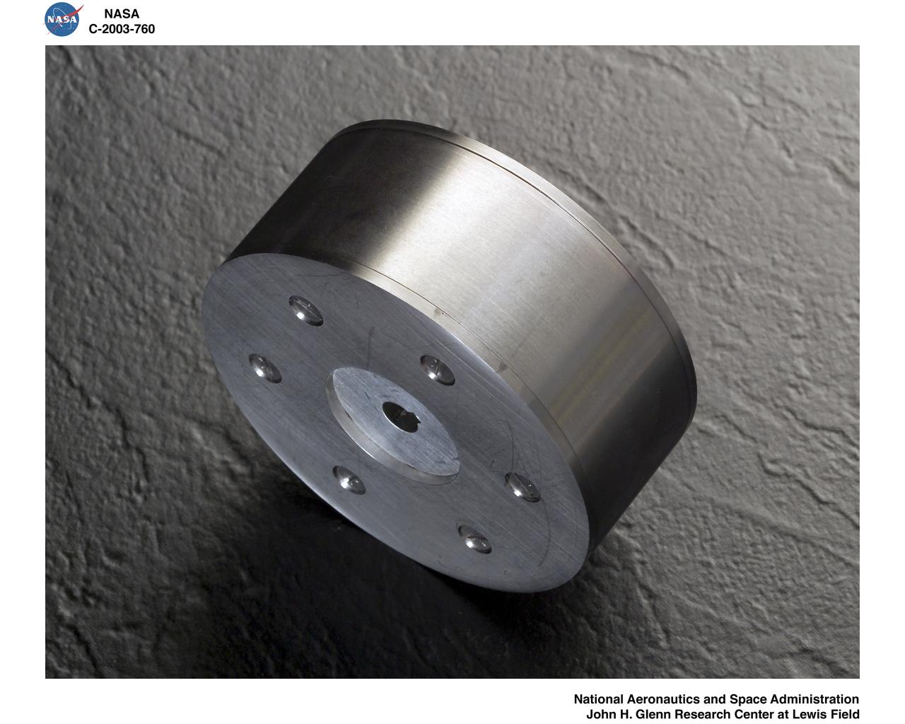
LEVITATED DUCTED FAN TEST ROTOR
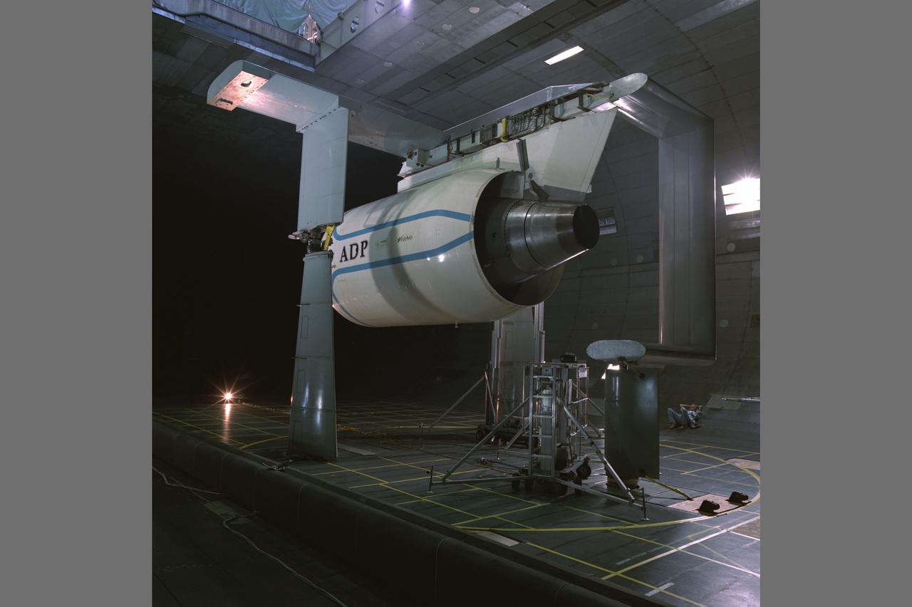
Pratt & Whitney Advanced Ducted Propulsor (ADP) Engine Test-590 in the NASA Ames 40x80ft Subsonic Wind Tunnel. The Pratt & Whitney Advanced Ducted Prop (ADP) demonstrator undergoing acoustic and fan performance testing. ADP technology could lead to decreased fuel consumption and noise.
Pratt & Whitney Advanced Ducted Propulsor (ADP) Engine Test-590 in NASA Ames 40x80ft Subsonic Wind Tunnel. The Pratt & Whitney advanced ducted prop (ADP) demonstrator undergoing acoustic and fan performance testing. ADP technology could lead to decreased fuel consumption and noise.

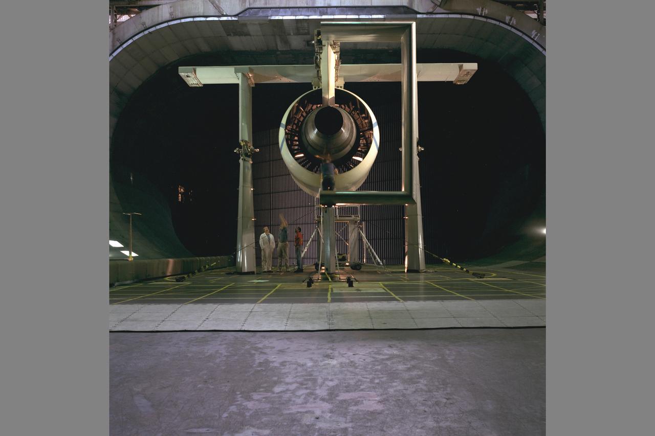
ALLISON DUCTED FAN IN 9X15 FOOT LOW SPEED WIND TUNNEL
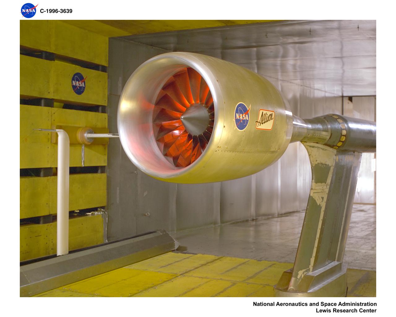
ALLISON DUCTED FAN IN 9X15 FOOT LOW SPEED WIND TUNNEL
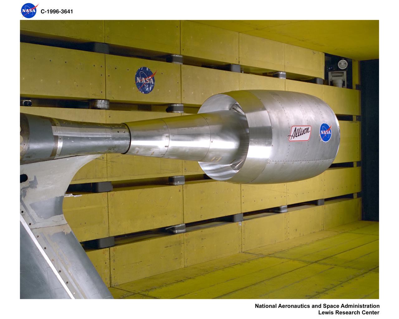
ALLISON DUCTED FAN IN 9X15 FOOT LOW SPEED WIND TUNNEL

An inlet duct lowered into the 20-foot diameter test section of the Altitude Wind Tunnel at the National Advisory Committee for Aeronautics (NACA) Lewis Flight Propulsion Laboratory. Engines and hardware were prepared in the facility’s shop area. The test articles were lifted by a two-rail Shaw box crane through the high-bay and the second-story test chamber before being lowered into the test section. Technicians then spent days or weeks hooking up the supply lines and data recording telemetry. The engines were mounted on wingspans that stretched across the test section. The wingtips attached to the balance frame’s trunnions, which could adjust the angle of attack. The balance frame included six devices that recorded data and controlled the engine. The measurements were visible in banks of manometer boards next to the control room. Photographs recorded the pressure levels in the manometer tubes, and the computing staff manually converted the data into useful measurements. A mechanical pulley system was used to raise and lower the tunnel’s large clamshell lid into place. The lid was sealed into place using hand-turned locks accessible from the viewing platform. The lid had viewing windows above and below the test article, which permitted the filming and visual inspection of the tests.
3/4 front view offull scale X-22A ducted fan model. Chuck Greco
3/4 front view of full scale X-22A ducted fan model. Chuck Greco
REASSEMBLY OF DUCT LAB SWT MACH 4-5 NOZZLE WITH MACH 2.0 INJECTION
3/4 front view of full scale X-22A ducted fan model. Chuck Greco
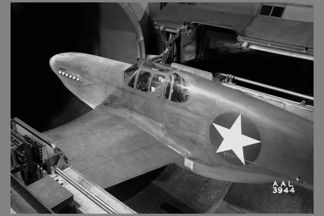
3/4 rear view of a XP-51B airplane mounted in the 16ft w.t. (Ames contribution to the solution of the duct-rumble problem)
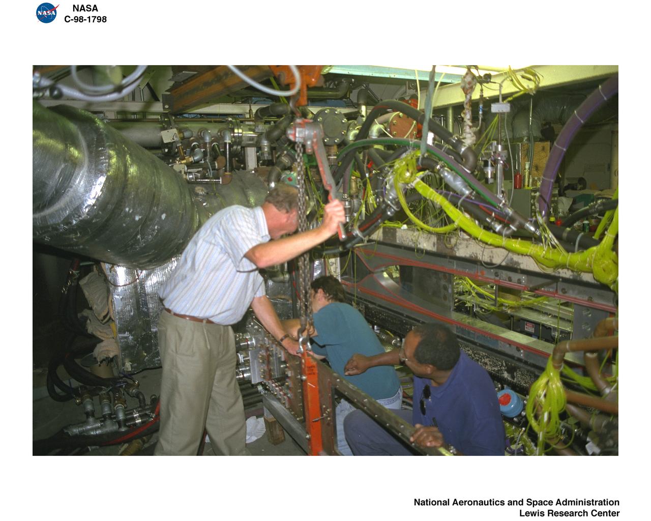
REASSEMBLY OF DUCT LAB SWT MACH 4-5 NOZZLE WITH MACH 2.0 INJECTION
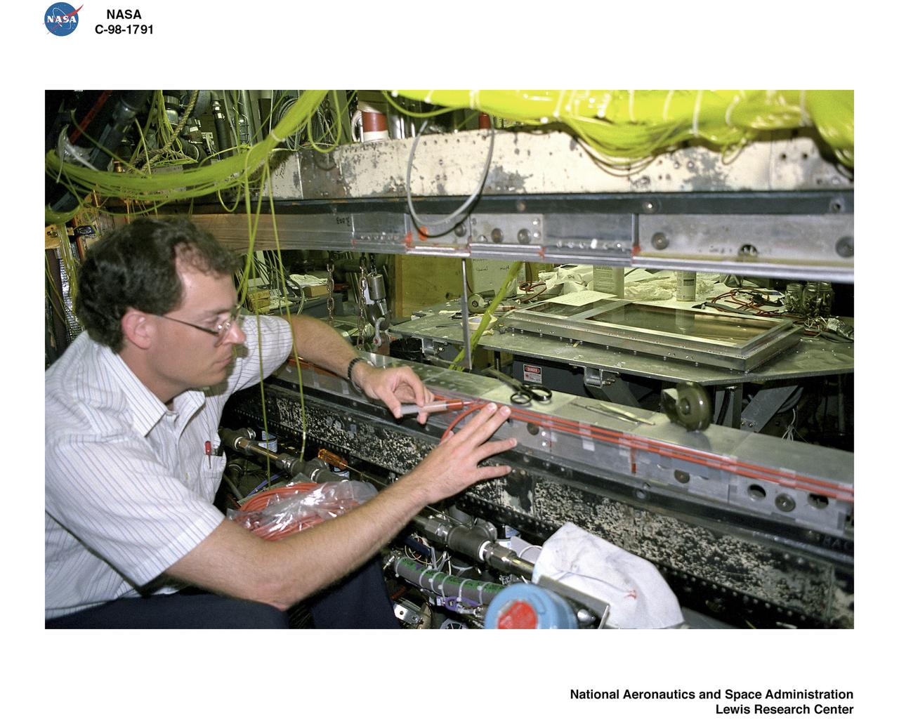
REASSEMBLY OF DUCT LAB SWT MACH 4-5 NOZZLE WITH MACH 2.0 INJECTION
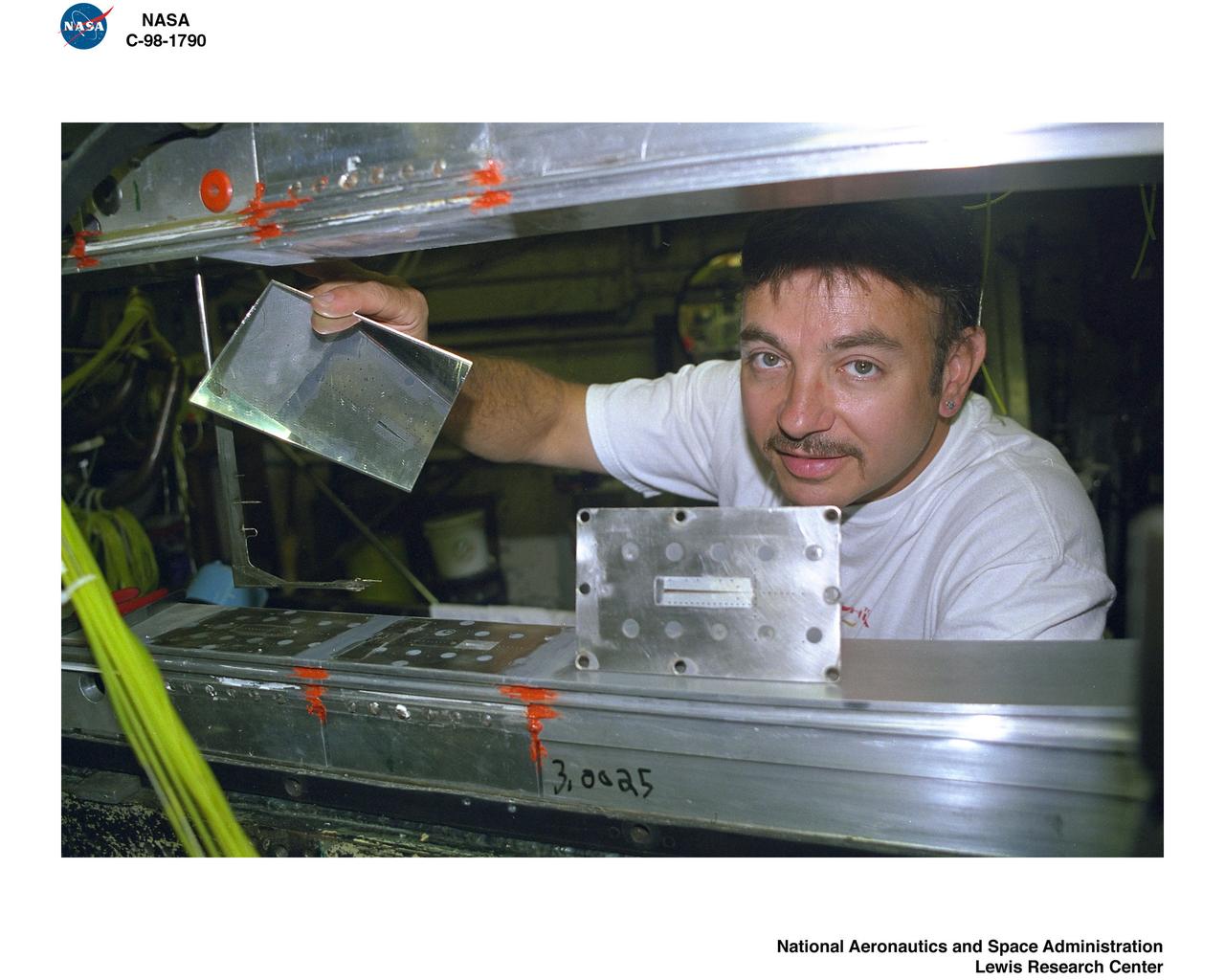
REASSEMBLY OF DUCT LAB SWT MACH 4-5 NOZZLE WITH MACH 2.0 INJECTION
3/4 front view of modified production scoop on XP-51B airplane mounted in the 16ft w.t. (Ames contribution to the solution of the duct-rumble problem)

Isolation of human mammary epithelial cells (HMEC) from breast cancer susceptible tissue; A: Duct element recovered from breast tissue digest. B: Outgrowth of cells from duct element in upper right corner cultured in a standard dish; most cells spontaneousely die during early cell divisions, but a few will establish long-term growth. C: Isolate of long-term frowth HMEC from outgrowth of duct element; cells shown soon after isolation and in early full-cell contact growth in culture in a dish. D: same long-term growth HMEC, but after 3 weeks in late full-cell contact growth in a continuous culture in a dish. Note attempts to reform duct elements but this in two demensions in a dish rather than in three dimensions in tissue. NASA's Marshall Space Flight Center (MSFC) is sponsoring research with Bioreactors, rotating wall vessels designed to grow tissue samples in space, to understand how breast cancer works. This ground-based work studies the growth and assembly of human mammary epithelial cell (HMEC) from breast cancer susceptible tissue. Radiation can make the cells cancerous, thus allowing better comparisons of healthy vs. tunorous tissue. Credit: Dr. Robert Richmond, NASA/Marshall Space Flight Center (MSFC).
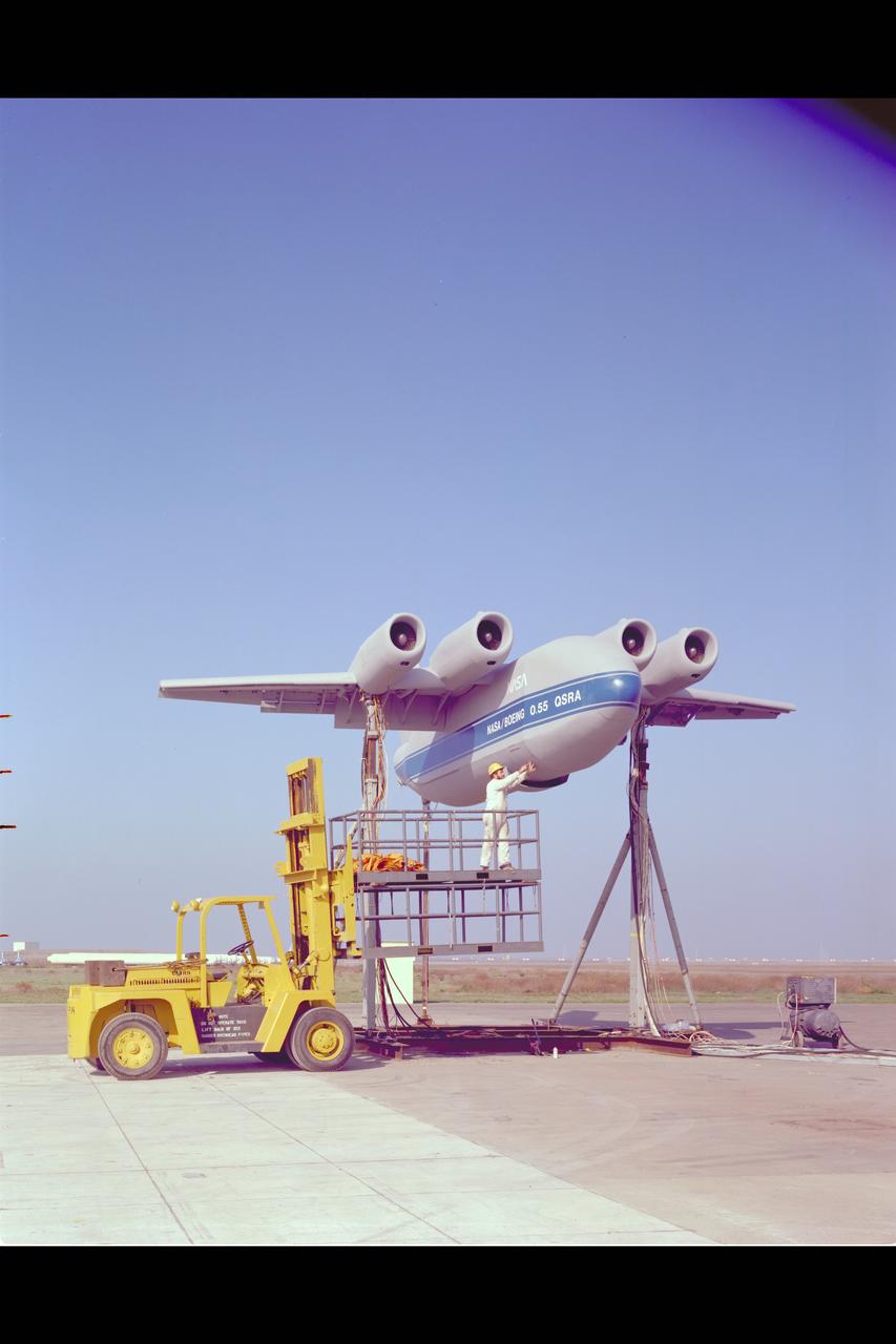
QSRA (Quiet Short-Haul Research Aircraft) S-Duct Test: Static test facility installation (Appeared on the cover of the Avaiation Week & Space Technology on March 21, 1977)
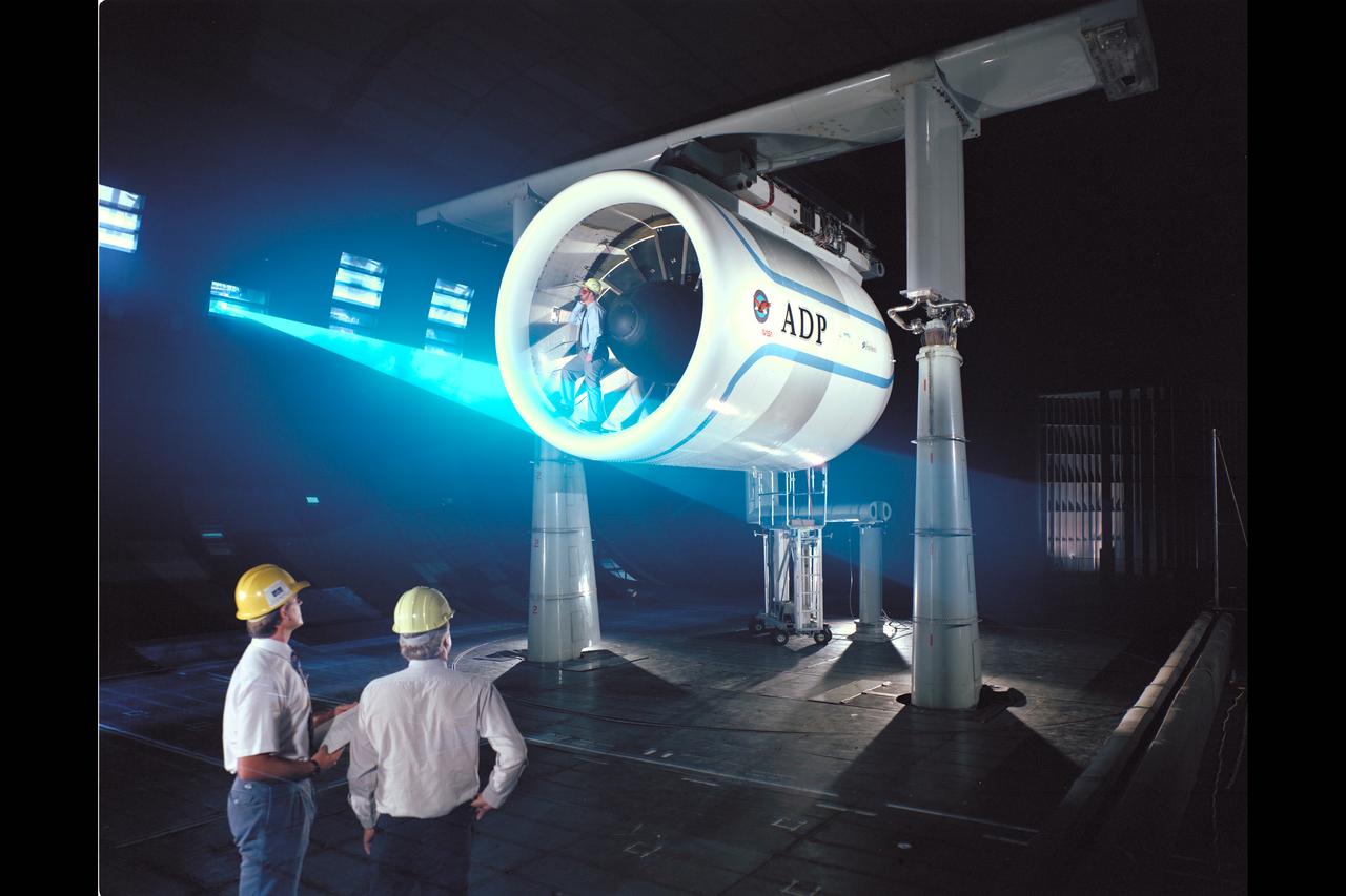
Pratt & Whitney Advanced Ducted Propulsor (ADP) Engine Test-590 in NASA Ames 40x80ft Subsonic Wind Tunnel. The Pratt & Whitney advanced ducted prop (ADP) demonstrator undergoing acoustic and fan performance testing. ADP technology could lead to decreased fuel consumption and noise. Shown here are NASA Ames engineers Peter Zell (left) and Dr Clifton Horne (right) preparing for a laser light sheet for a flow visualization test. Shown standing in the nacelle of the ADP is John Girvin, senior test engineer for Pratt & Whitney.
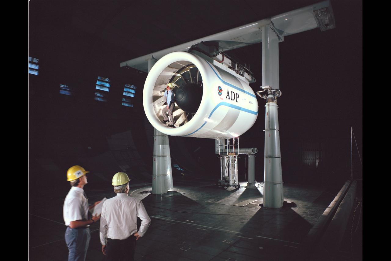
Pratt & Whitney Advanced Ducted Propulsor (ADP) Engine Test-590 in NASA Ames 40x80ft Subsonic Wind Tunnel. The Pratt & Whitney advanced ducted prop (ADP) demonstrator undergoing acoustic and fan performance testing. ADP technology could lead to decreased fuel consumption and noise. Shown here are NASA Ames engineers Peter Zell (left) and Dr Clifton Horne (right) preparing for a laser light sheet for a flow visualization test. Shown standing in the nacelle of the ADP is John Girvin, senior test engineer for Pratt & Whitney.
STS096-357-013 (27 May - 6 June 1999) --- Astronaut Kent V. Rominger, mission commander, participates in the move of supplies from Discovery to the International Space Station (ISS). Rominger was joined by four other American astronauts, a Canadian astronaut and a Russian cosmonaut for almost ten days in space, most of which were devoted to preparing the ISS.
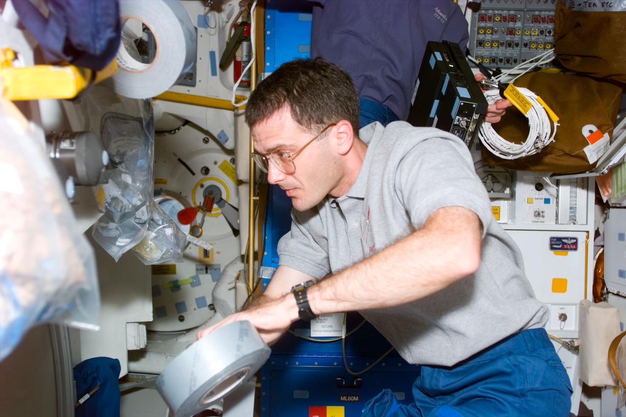
STS081-E-5009 (12 Jan. 1997) --- Astronaut Peter J. K. (Jeff) Wisoff, mission specialist, helps carry out tasks of readying the Space Shuttle Atlantis for almost ten days in space, securing supplies with a piece of gaffer's tape. Currently, Wisoff is accompanied by five crew mates, among whom one - astronaut Jerry M. Linenger - will be exchanged in a few days for John E. Blaha, who has been aboard Russia's Mir Space Station for several months, as a cosmonaut guest researcher. Docking of Atlantis with Mir is scheduled for the middle of the week. The scene was recorded with an Electronic Still Camera (ESC) and later downlinked to flight controllers in Houston, Texas.
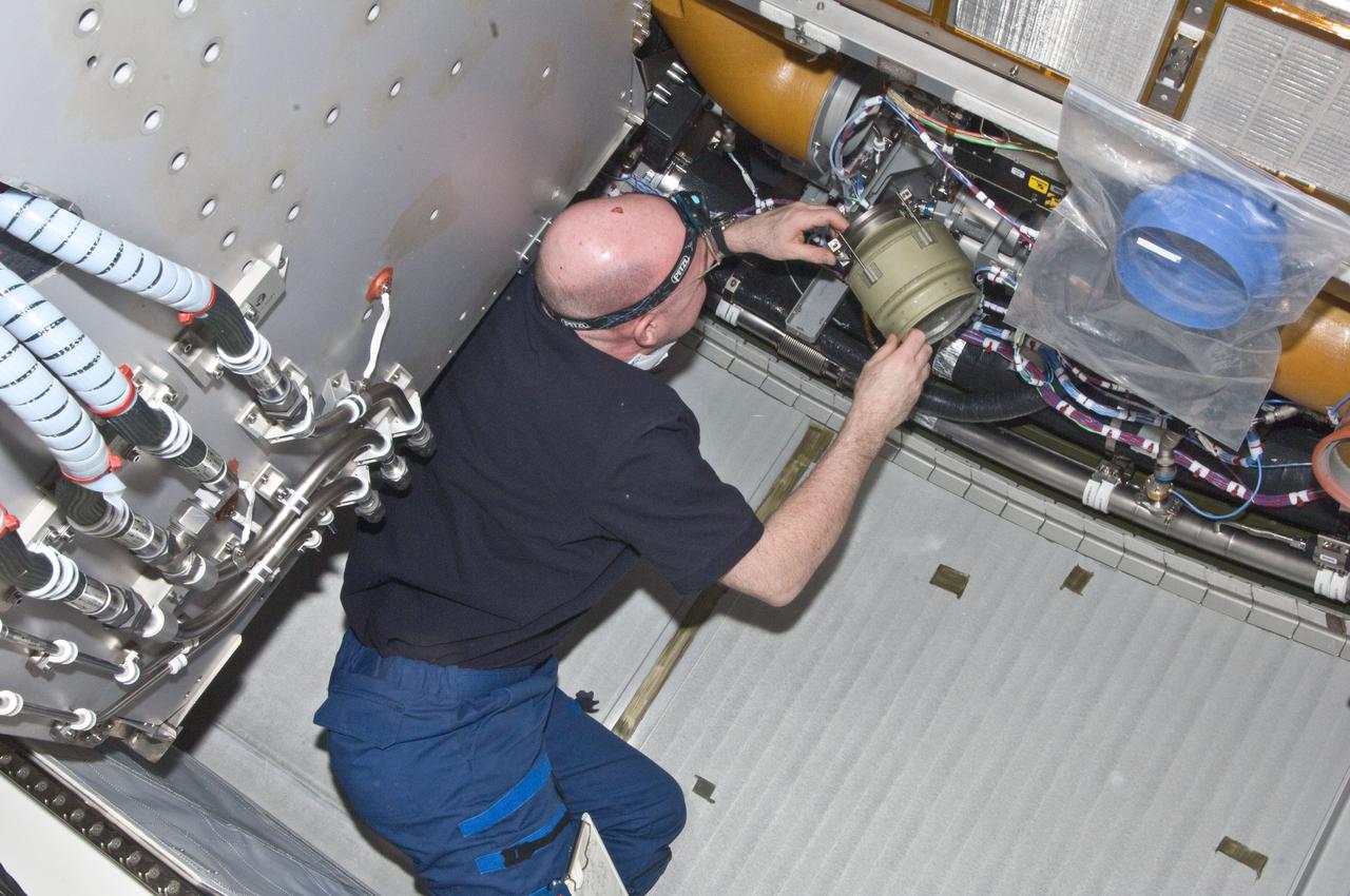
ISS030-E-129474 (22 Feb. 2012) --- European Space Agency astronaut Andre Kuipers, Expedition 30 flight engineer, performs the scheduled inspection and extensive cleanup of ventilation systems and ventilation ducts in the Columbus laboratory of the International Space Station.
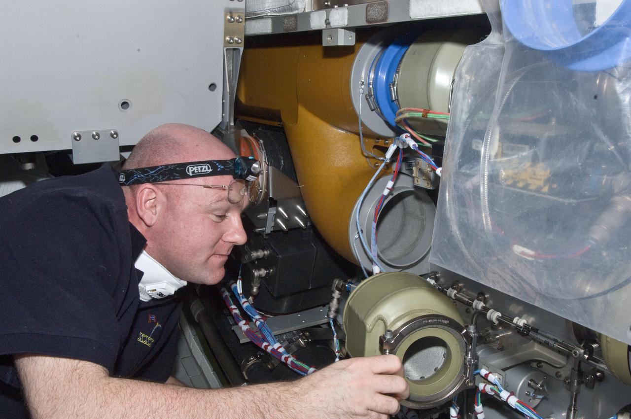
ISS030-E-129477 (22 Feb. 2012) --- European Space Agency astronaut Andre Kuipers, Expedition 30 flight engineer, performs the scheduled inspection and extensive cleanup of ventilation systems and ventilation ducts in the Columbus laboratory of the International Space Station.
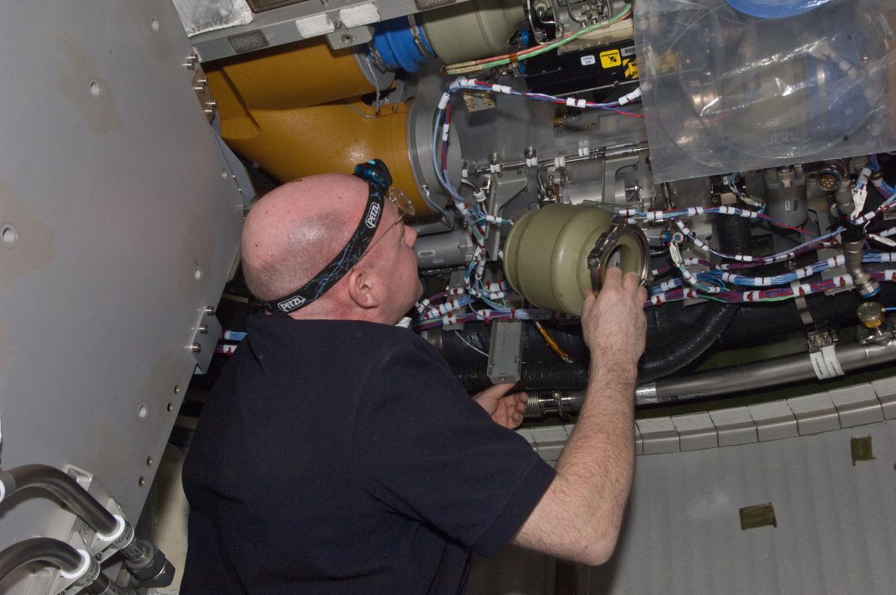
ISS030-E-129476 (22 Feb. 2012) --- European Space Agency astronaut Andre Kuipers, Expedition 30 flight engineer, performs the scheduled inspection and extensive cleanup of ventilation systems and ventilation ducts in the Columbus laboratory of the International Space Station.
3/4 front, top view of Noriar Lift Engine Pod installation in Ames 40x80 foot wind tunnel
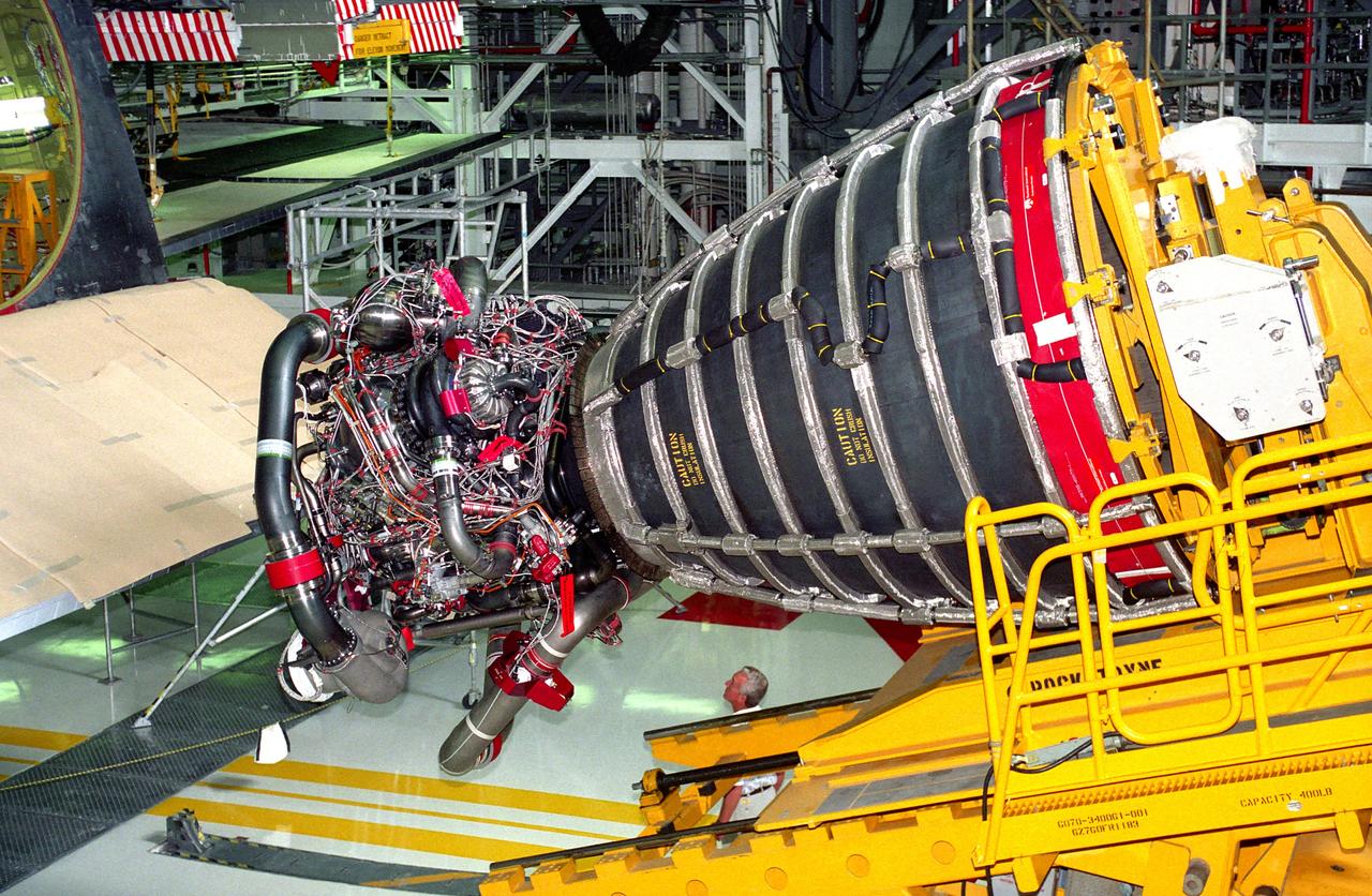
KENNEDY SPACE CENTER, FLA. - Space Shuttle Main Engine (SSME) No. 2036, the first of the new Block 1 engines to fly, awaits installation into position one of the orbiter Discovery in Orbiter Processing Facility 2 during preparation of the spaceplane for the STS-70 mission. The advanced powerplant features a new high-pressure liquid oxygen turbopump, a two-duct powerhead, a baffleless main injector, a single-coil heat exchanger and start sequence modifications. These modifications are designed to improve both engine performance and safety.
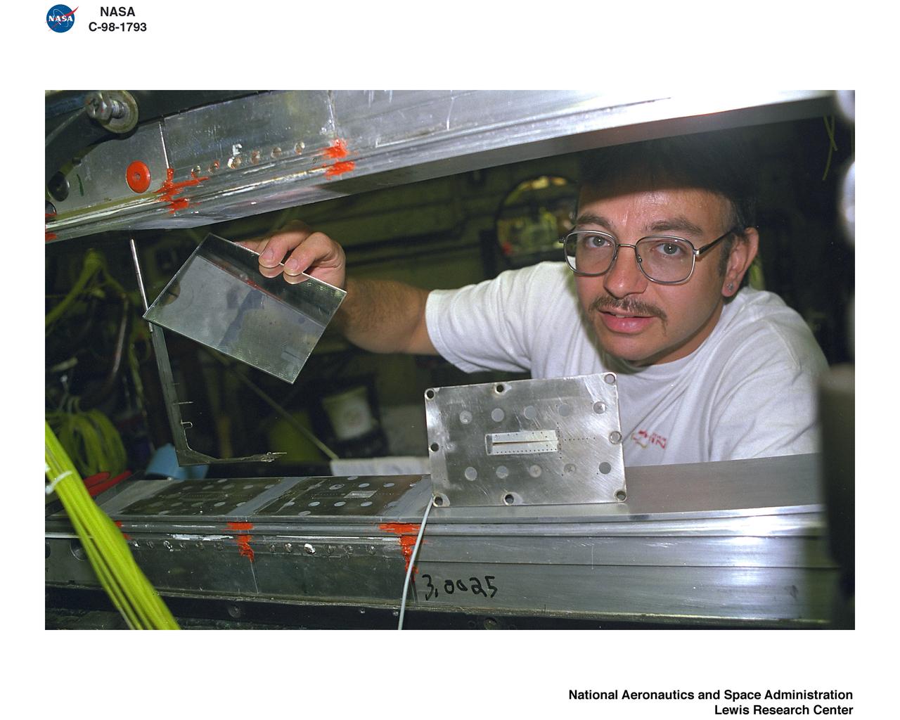
Acoustic Casing Treatment Testing Completed in the W-8 Single Stage Axial Compressor Facility at NASA Glenn. Four different over-the-rotor acoustic casing treatment concepts were tested along with two baseline configurations. Testing included steady-aerodynamic measurements of fan performance, hotfilm turbulence measurements, and inlet acoustic measurements with an in-duct array.
Acoustic Casing Treatment Testing Completed in the W-8 Single Stage Axial Compressor Facility at NASA Glenn. Four different over-the-rotor acoustic casing treatment concepts were tested along with two baseline configurations. Testing included steady-aerodynamic measurements of fan performance, hotfilm turbulence measurements, and inlet acoustic measurements with an in-duct array.
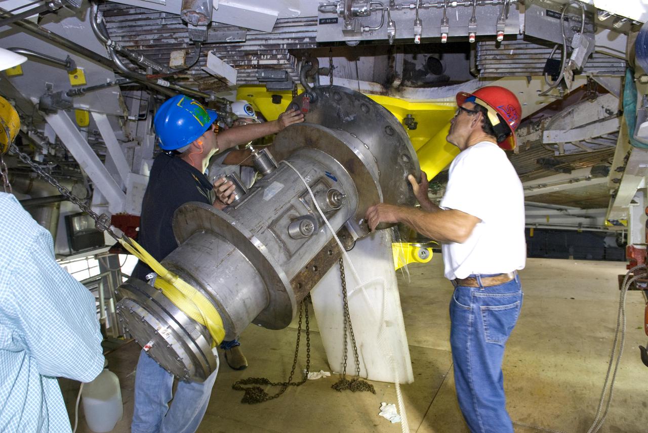
John C. Stennis Space Center employees remove space shuttle main engine run ducts from the A-2 Test Stand engine deck Oct. 25, 2010. Testing of space shuttle main engines concluded in July 2009. Stennis is preparing the A-2 Test Stand for testing the next-generation J-2X rocket engine being developed. Testing of the new engine is scheduled to begin in 2011.
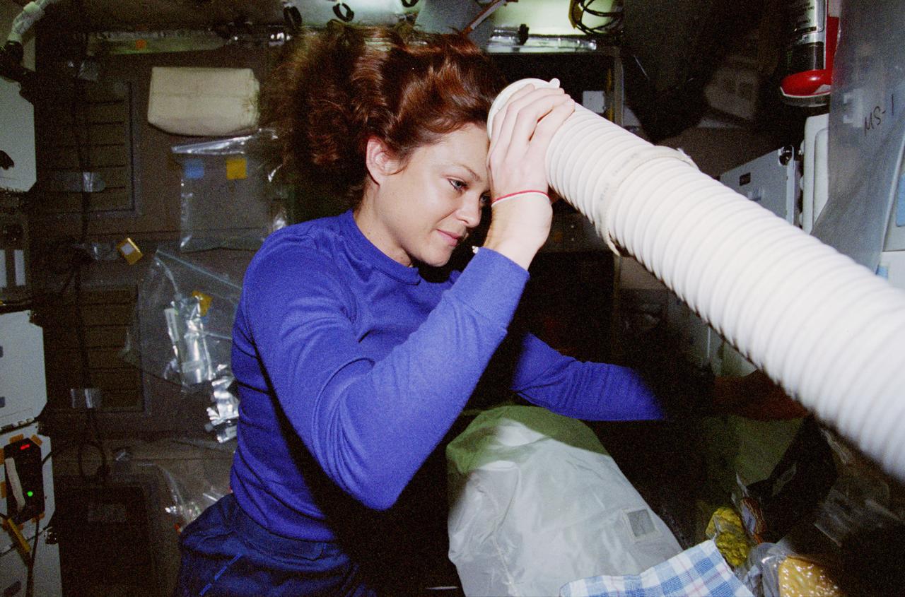
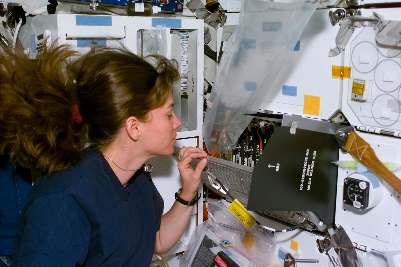
STS080-361-007 (19 Nov.-7 Dec. 1996) --- Astronaut Tamara E. Jernigan, STS-80 mission specialist, improvises onboard the space shuttle Columbia. Having just washed her hair, Jernigan temporarily "borrowed" a duct from the orbiter's air conditioning system to dry it. The off-duty activity was recorded with a 35mm camera.
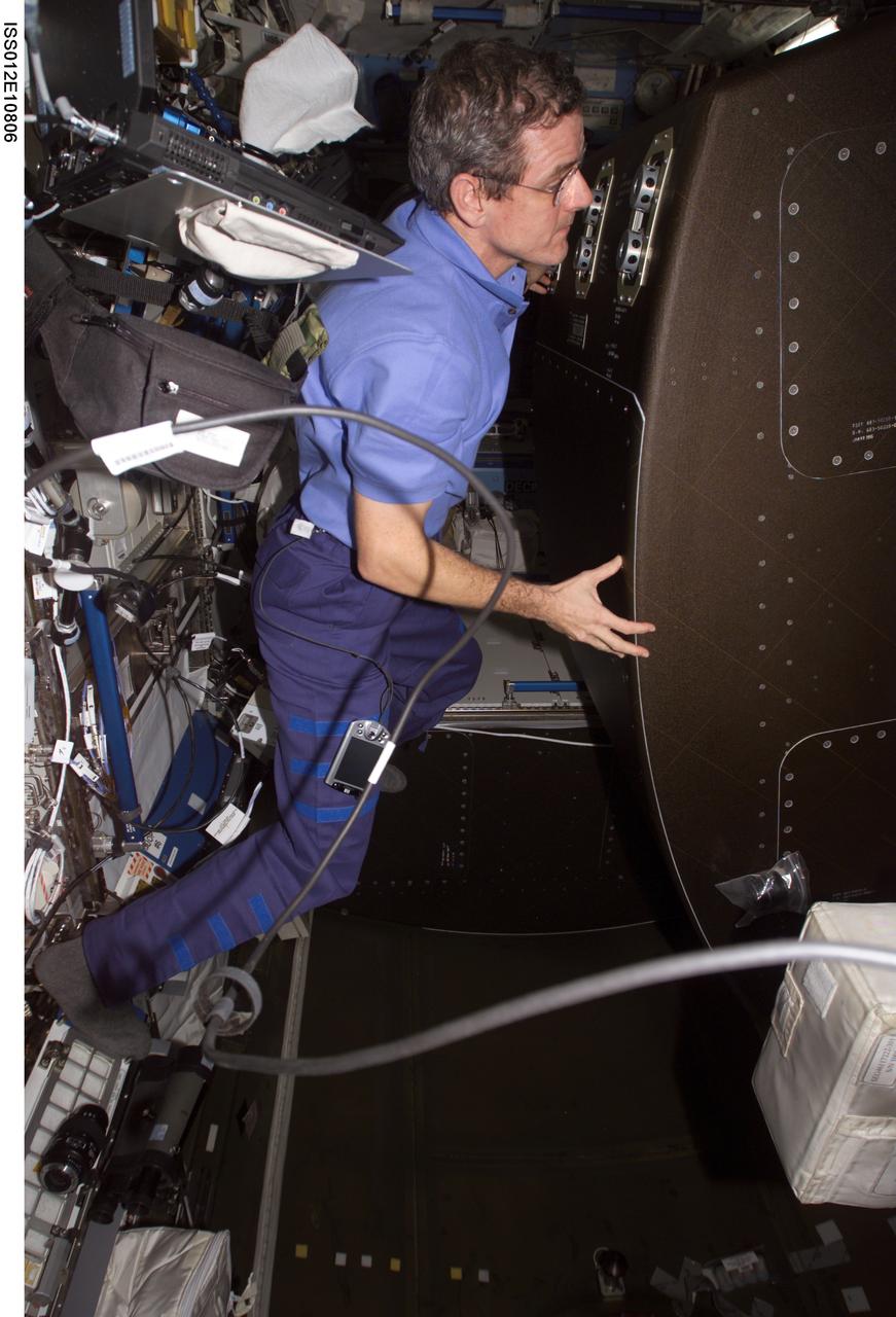
ISS012-E-10806 (9 December 2005) --- Astronaut William S. (Bill) McArthur Jr., Expedition 12 commander and NASA space station science officer, rotates the Crew Health Care System (CHeCS) rack in order to access the Avionics Air Assembly (AAA) air ducts during in-flight maintenance (IFM) in the Destiny laboratory of the International Space Station.
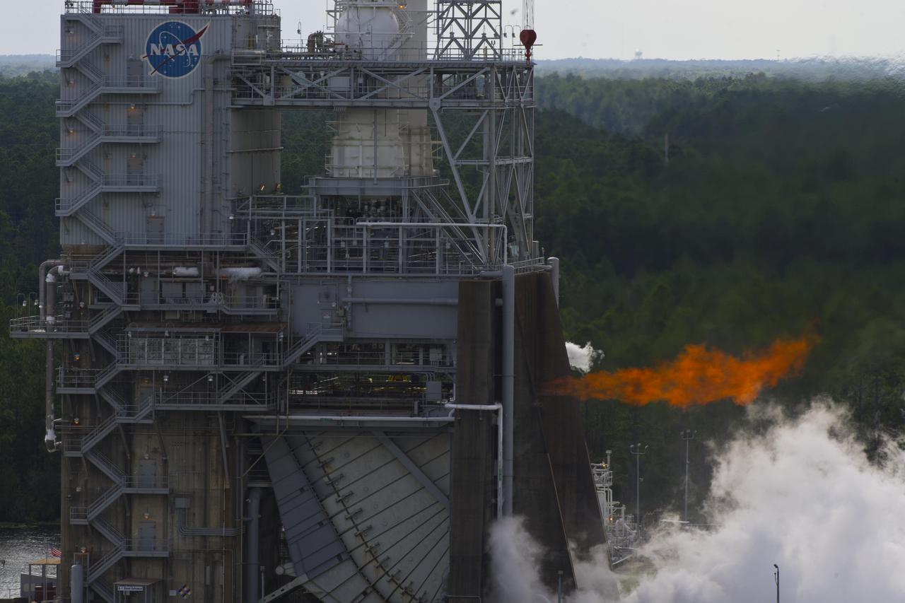
NASA conducted a long-duration test of the J-2X powerpack, 1,261 seconds total, on the A-1 Test Stand at Stennis Space Center on Aug. 16, marking another step in development of the next-generation rocket engine. The powerpack is a system of components on the top portion of the J-2X engine, including the gas generator, oxygen and fuel turbopumps, and related ducts and valves.
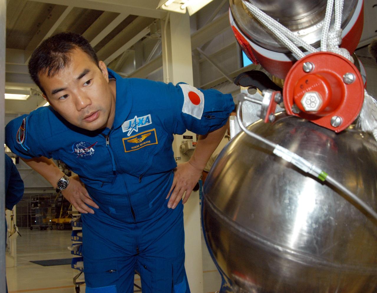
KENNEDY SPACE CENTER, FLA. -- STS-114 Mission Specialist Soichi Noguchi looks closely at low pressure oxidizer duct in the Space Shuttle Main Engine Shop at KSC. He and other crew members are touring several areas on the Center. The STS-114 mission is Logistics Flight 1, which is scheduled to deliver supplies and equipment plus the external stowage platform to the International Space Station.
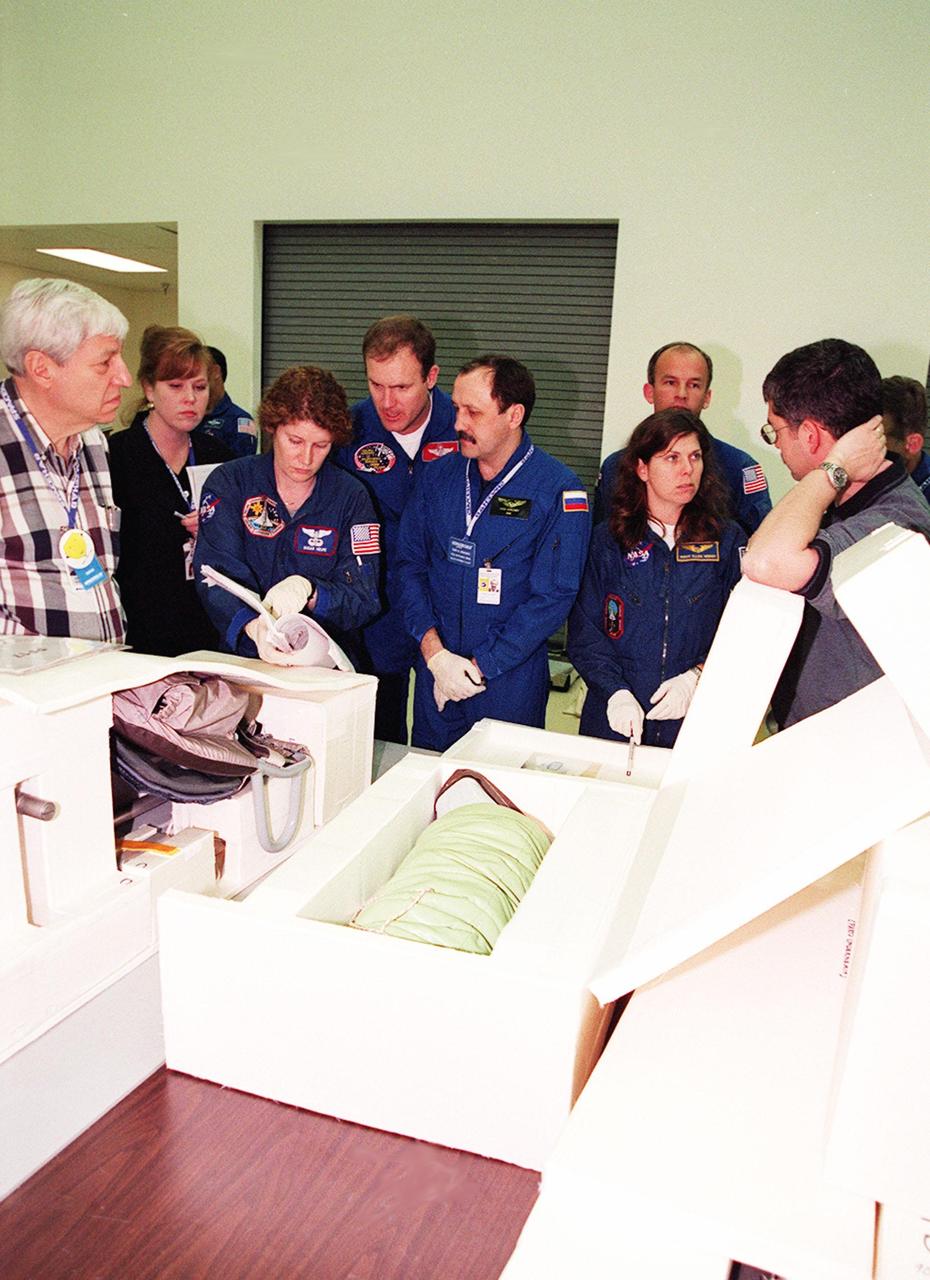
KENNEDY SPACE CENTER, FLA. -- At SPACEHAB, in Cape Canaveral, Fla., STS-101 Mission Specialists Susan Helms and Yuri Usachev, with Commander James Halsell, handle an air duct to be installed during their mission to the International Space Station. The air duct is for the Russian module Zarya to improve ventilation. At right are Mission Specialists Jeffrey Williams and Mary Ellen Weber. In the background at left is Pilot Scott Horowitz. Not shown is Mission Specialist James Voss. The crew is taking part in Crew Equipment Interface Test (CEIT) activities to learn about some of the equipment they will be working with on their mission to the Space Station. The STS-101 crew will be responsible for preparing the Space Station for the arrival of the Zvezda Service Module, expected to be launched by Russia in July 2000. Also, the crew will conduct one space walk to perform maintenance on the Space Station and deliver logistics and supplies. This will be the third assembly flight for the Space Station. STS-101 is scheduled to launch no earlier than April 13 from Launch Pad 39A
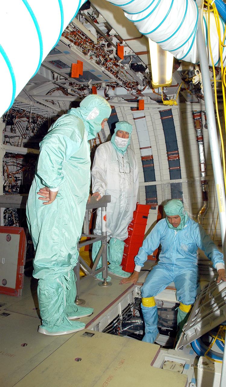
KENNEDY SPACE CENTER, FLA. - In the middeck of Endeavour, in the Orbiter Processing Facility, Center Director Jim Kennedy (far left) watches as a technician gets ready to lower himself through the LiOH door into the Environmental Control and Life Support System (ECLSS) bay. LiOH refers to lithium hydroxide, canisters of which are stored in the ECLSS bay under the middeck floor. During flight, cabin air from the cabin fan is ducted to two LiOH canisters, where carbon dioxide is removed and activated charcoal removes odors and trace contaminants. Kennedy is taking an opportunity to learn first-hand what workers are doing to enable Return to Flight. Endeavour is in an Orbiter Major Modification period.
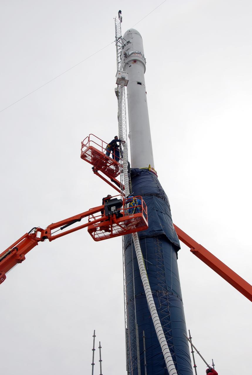
VANDENBERG AIR FORCE BASE, Calif. -- On Launch Complex 576-E at Vandenberg Air Force Base in California, workers in the bucket trucks are securing the fairing ducting, GN2 purge line, and cable harnesses to the umbilical mast attached to Orbital Sciences' Taurus XL rocket. Atop the rocket is NASA's Orbiting Carbon Observatory, or OCO, which is scheduled to launch Feb. 24 from Vandenberg. The spacecraft will collect precise global measurements of carbon dioxide (CO2) in the Earth's atmosphere. Scientists will analyze OCO data to improve our understanding of the natural processes and human activities that regulate the abundance and distribution of this important greenhouse gas. Photo credit: NASA/Richard Nielsen, VAFB
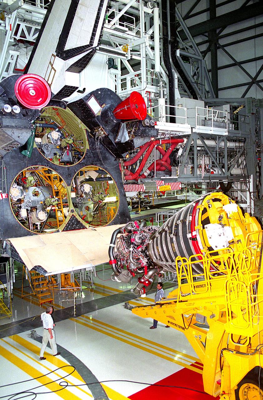
KENNEDY SPACE CENTER, FLA. - A Space Shuttle Main Engine (SSME) hoist prepares to lift the first Block 1 engine to be installed in an orbiter into the number one position on Discovery while the spaceplane is being prepared for the STS-70 mission in the high bay of Orbiter Processing Facility 2. The new engine, SSME No. 2036, features a new high-pressure liquid oxygen turbopump, a two-duct powerhead, a baffleless main injector, a single-coil heat exchanger and start sequence modifications. The other two main engines to be used during the liftoff of the STS-70 mission are of the existing Phase II design.
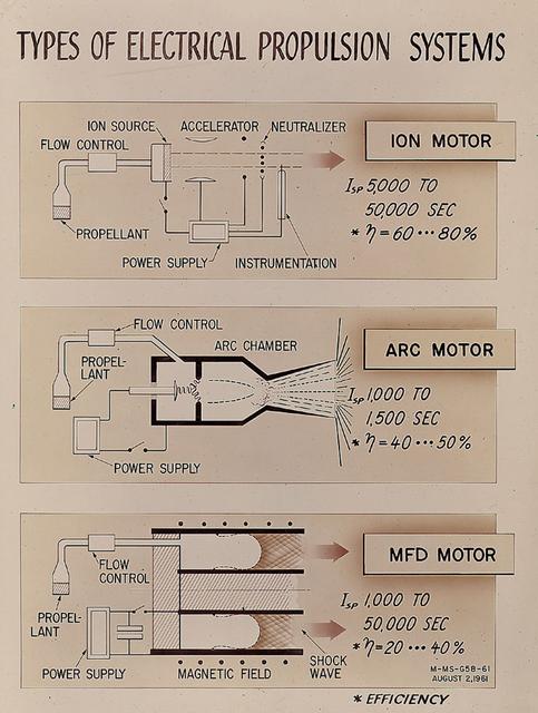
As presented by Gerhard Heller of Marshall Space Flight Center's Research Projects Division in 1961, this chart illustrates three basic types of electric propulsion systems then under consideration by NASA. The ion engine (top) utilized cesium atoms ionized by hot tungsten and accelerated by an electrostatic field to produce thrust. The arc engine (middle) achieved propulsion by heating a propellant with an electric arc and then producing an expansion of the hot gas or plasma in a convergent-divergent duct. The electromagnetic, or MFD engine (bottom) manipulated strong magnetic fields to interact with a plasma and produce acceleration.
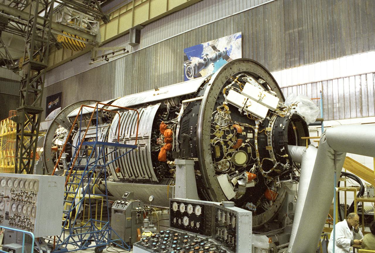
In this photograph, Russians are working on the aft portion of the United States-funded, Russian-built Functional Cargo Bay (FGB) also known as Zarya (Russian for sunrise). Built at Khrunichev, the FGB began pre-launch testing shortly after this photo was taken. Launched by a Russian Proton rocket from the Baikonu Cosmodrome on November 20, 1998, Zarya was the first element of the International Space Station (ISS) followed by the U.S. Unity Node. The aft docking mechanism, Pirs, on the far right with ventilation ducting rurning through it, will be docked with the third Station element, the Russian Service Module, or Zvezda.
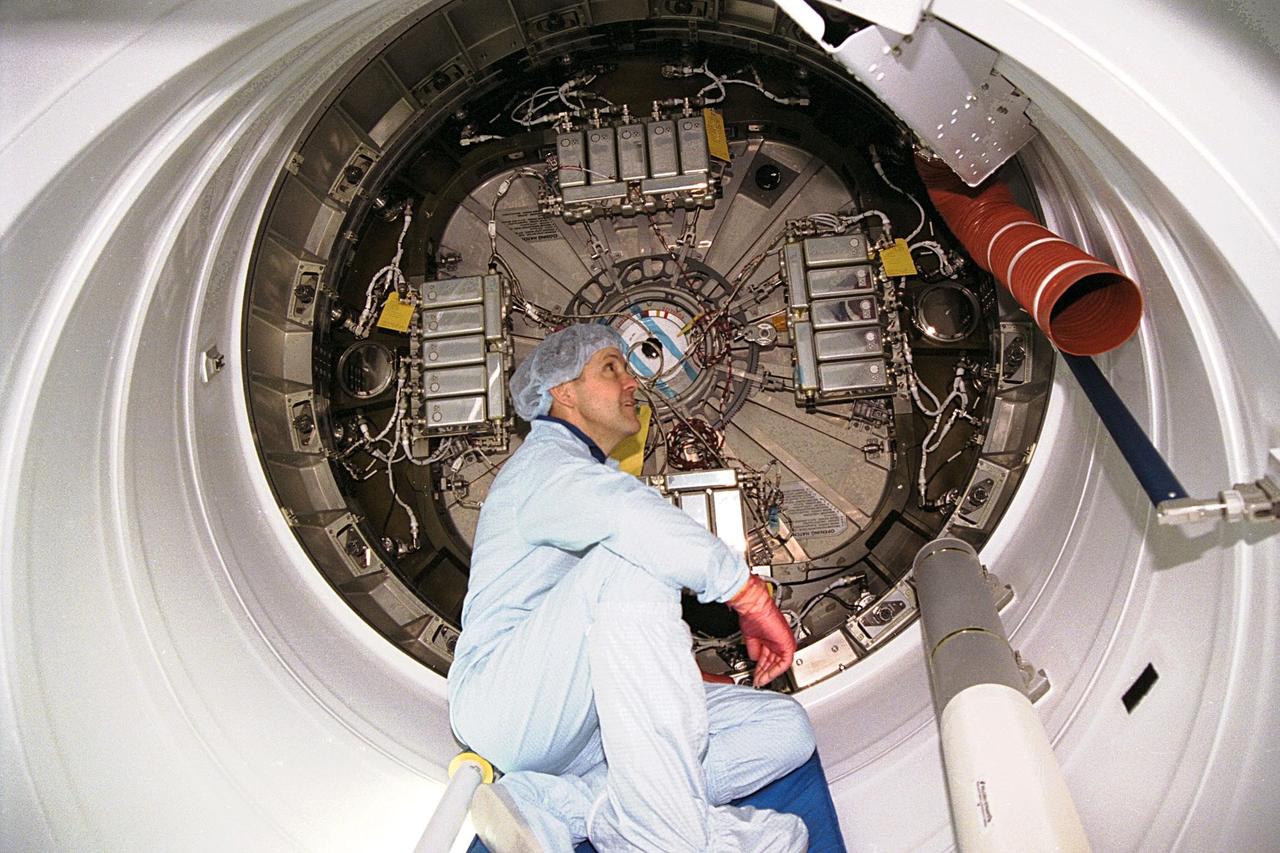
KENNEDY SPACE CENTER, FLA. -- Commander Bob Cabana participates in the Crew Equipment Interface Test (CEIT) for STS-88 in KSC's Space Station Processing Facility. The CEIT gives astronauts an opportunity to get a hands-on look at the payloads with which they will be working on-orbit. Here, Cabana sits inside the Pressurized Mating Adapter-1 (PMA-1) for a close-up look at some of the connecting ducts and wires. Node 1 of the International Space Station (ISS) is behind him. STS-88, the first ISS assembly flight, is targeted for launch in July 1998 aboard Space Shuttle Endeavour
S93-E-5043 (24 July 1999) --- Astronaut Catherine G. (Cady) Coleman, mission specialist, checks the support system for the Plant Growth Investigations in Microgravity 1 (PGIM-1) experiment on Columbia's middeck. The photo was recorded with an electronic still camera (ESC) on Flight Day 2.
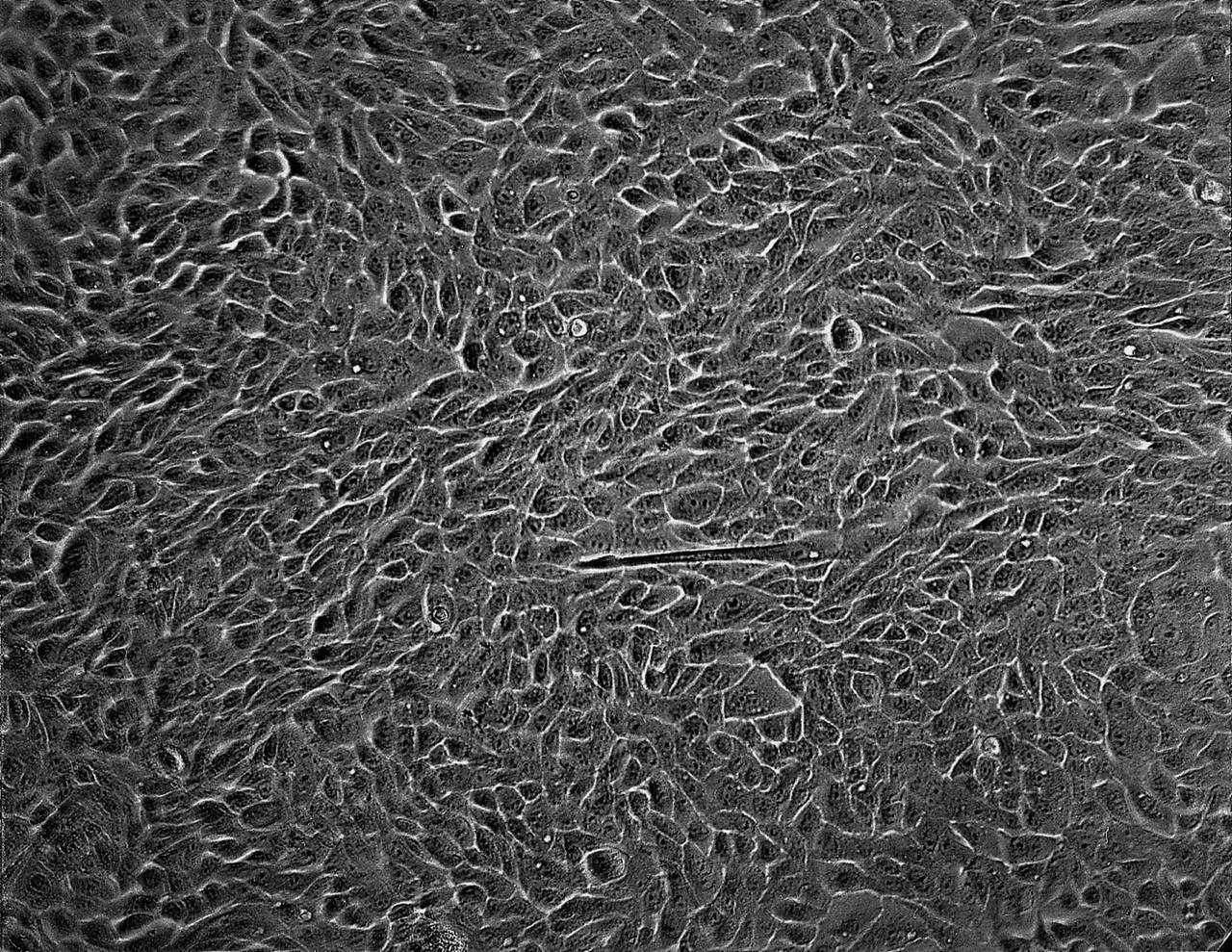
Isolation of human mammary epithelial cells (HMEC) from breast cancer susceptible tissue. Isolate of long-term growth human mammary epithelial cells (HMEC) from outgrowth of duct element; cells shown soon after isolation and early in culture in a dish. NASA's Marshall Space Flight Center (MSFC) is sponsoring research with Bioreactors, rotating wall vessels designed to grow tissue samples in space, to understand how breast cancer works. This ground-based work studies the growth and assembly of human mammary epithelial cell (HMEC) from breast cancer susceptible tissue. Radiation can make the cells cancerous, thus allowing better comparisons of healthy vs. tunorous tissue. Credit: Dr. Robert Tichmond, NASA/Marshall Space Flight Center (MSFC).
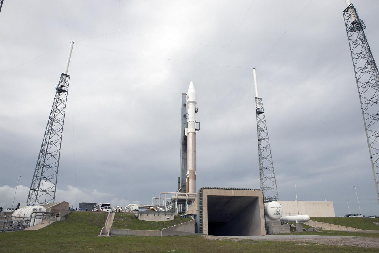
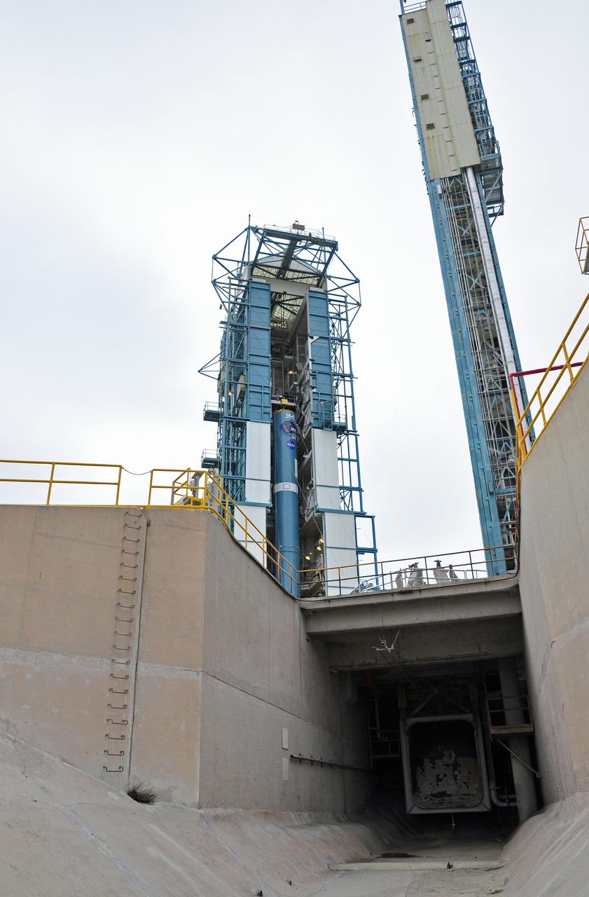
CAPE CANAVERAL, Fla. -- The United Launch Alliance Atlas V rocket carrying NASA’s Mars Atmosphere and Volatile EvolutioN, or MAVEN, spacecraft moves into position behind the flame exhaust duct at Space Launch Complex 41 on Cape Canaveral Air Force Station in Florida following a 20-minute journey from the Vertical Integration Facility. Rollout began on schedule with first motion at 9:57 a.m. EST. Launch is scheduled for Nov. 18 during a window that extends from 1:28 to 3:28 p.m. Once positioned in orbit above the Red Planet, MAVEN will study its upper atmosphere in unprecedented detail. For more information, visit: http://www.nasa.gov/mission_pages/maven/main/index.html. Photo credit: NASA/Kim Shiflett

Isolation of human mammary epithelial cells (HMEC) from breast cancer susceptible tissue. Same long-term growth human mammary epithelial cells (HMEC), but after 3 weeks in concinuous culture. Note attempts to reform duct elements, but this time in two dimensions in a dish rather that in three demensions in tissue. NASA's Marshall Space Flight Center (MSFC) is sponsoring research with Bioreactors, rotating wall vessels designed to grow tissue samples in space, to understand how breast cancer works. This ground-based work studies the growth and assembly of human mammary epithelial cell (HMEC) from breast cancer susceptible tissue. Radiation can make the cells cancerous, thus allowing better comparisons of healthy vs. tunorous tissue. Credit: Dr. Robert Tichmond, NASA/Marshall Space Flight Center (MSFC).
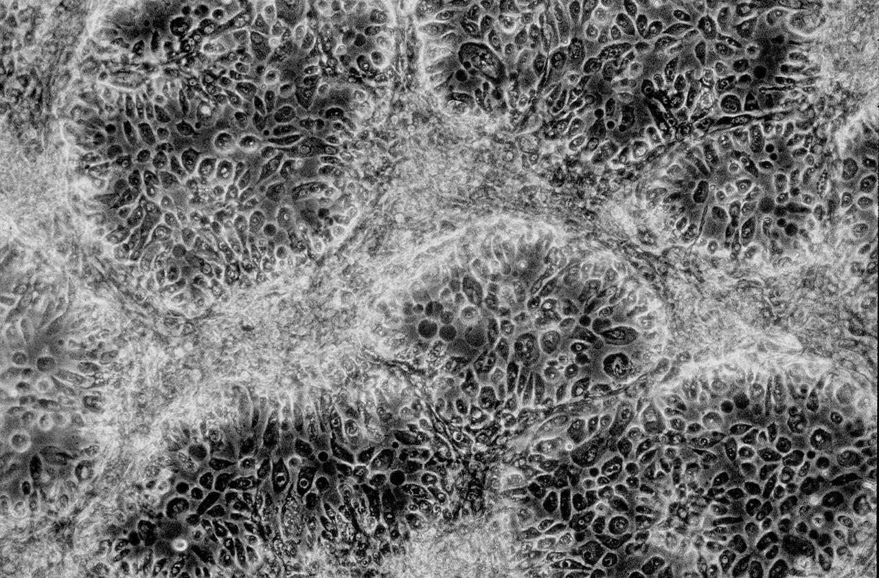
Isolation of human mammary epithelial cells (HMEC) from breast cancer susceptible tissue. Outgrowth of cells from duct element in upper right corner cultured in a standard dish; most cells spontaneously die during early cell divisions, but a few will establish long-term growth. NASA's Marshall Space Flight Center (MSFC) is sponsoring research with Bioreactors, rotating wall vessels designed to grow tissue samples in space, to understand how breast cancer works. This ground-based work studies the growth and assembly of human mammary epithelial cell (HMEC) from breast cancer susceptible tissue. Radiation can make the cells cancerous, thus allowing better comparisons of healthy vs. tunorous tissue. Credit: Dr. Robert Tichmond, NASA/Marshall Space Flight Center (MSFC).
VANDENBERG AIR FORCE BASE, Calif. – This view from the exhaust duct beneath Space Launch Complex 2 on Vandenberg Air Force Base in California reveals the first stage of the United Launch Alliance Delta II rocket for NASA's Soil Moisture Active Passive mission, or SMAP, undergoing processing in the mobile service tower. SMAP will provide global measurements of soil moisture and its freeze/thaw state. These measurements will be used to enhance understanding of processes that link the water, energy and carbon cycles, and to extend the capabilities of weather and climate prediction models. SMAP data also will be used to quantify net carbon flux in boreal landscapes and to develop improved flood prediction and drought monitoring capabilities. Launch is scheduled for November 2014. To learn more about SMAP, visit http://smap.jpl.nasa.gov. Photo credit: NASA/Randy Beaudoin
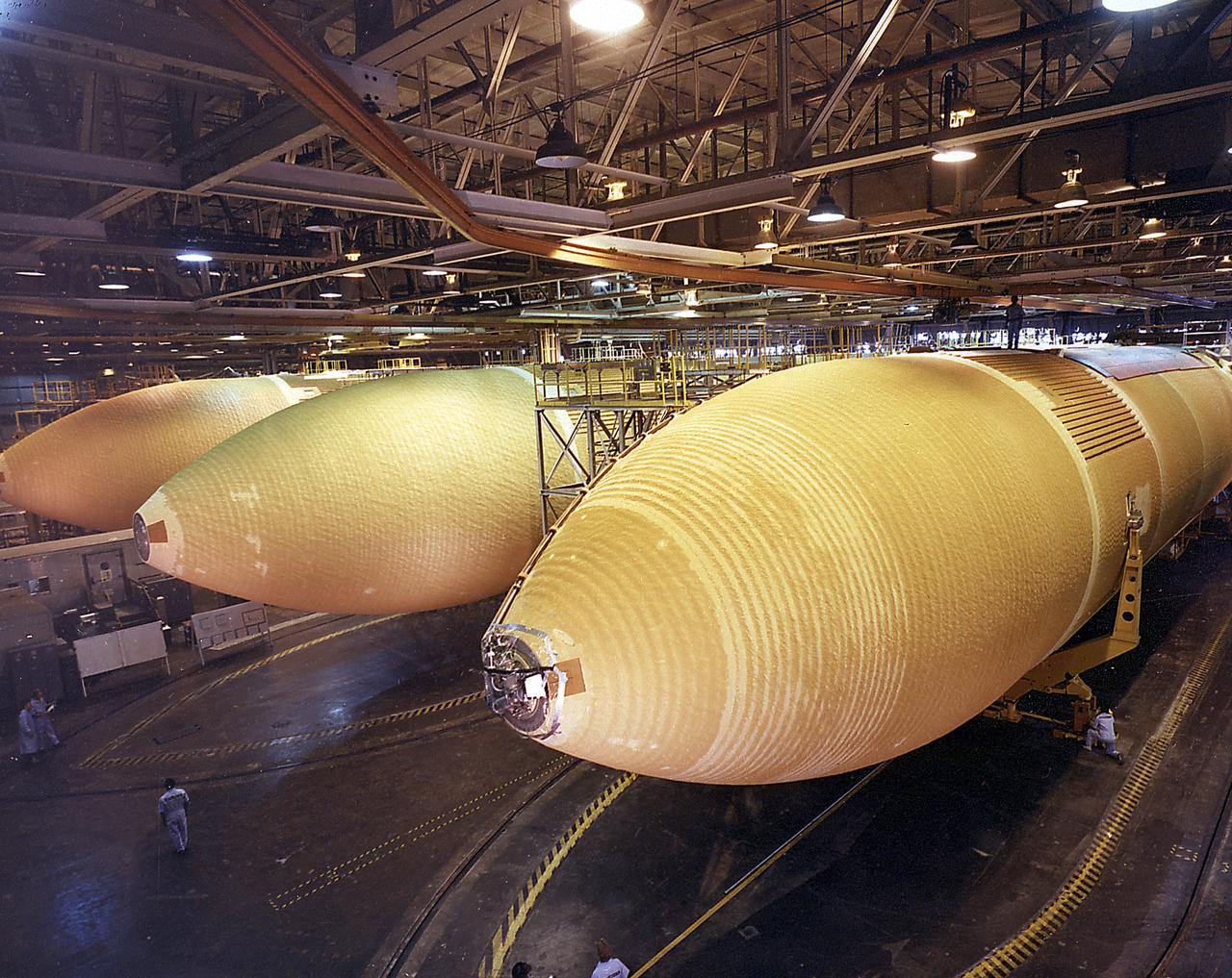
This photograph was taken during the final assembly phase of the Space Shuttle light weight external tanks (LWT) 5, 6, and 7 at the Michoud Assembly Facility in New Orleans, Louisiana. The giant cylinder, higher than a 15-story building, with a length of 154-feet (47-meters) and a diameter of 27.5-feet (8.4-meters), is the largest single piece of the Space Shuttle. During launch, the external tank (ET) acts as a backbone for the orbiter and solid rocket boosters. In separate, internal pressurized tank sections, the ET holds the liquid hydrogen fuel and liquid oxygen oxidizer for the Shuttle's three main engines. During launch, the ET feeds the fuel under pressure through 17-inch (43.2-centimeter) ducts which branch off into smaller lines that feed directly into the main engines. Some 64,000 gallons (242,260 liters) of fuel are consumed by the main engines each minute. Machined from aluminum alloys, the Space Shuttle's ET is the only part of the launch vehicle that currently is not reused. After its 526,000 gallons (1,991,071 liters) of propellants are consumed during the first 8.5 minutes of flight, it is jettisoned from the orbiter and breaks up in the upper atmosphere, its pieces falling into remote ocean waters. The Marshall Space Flight Center was responsible for developing the ET
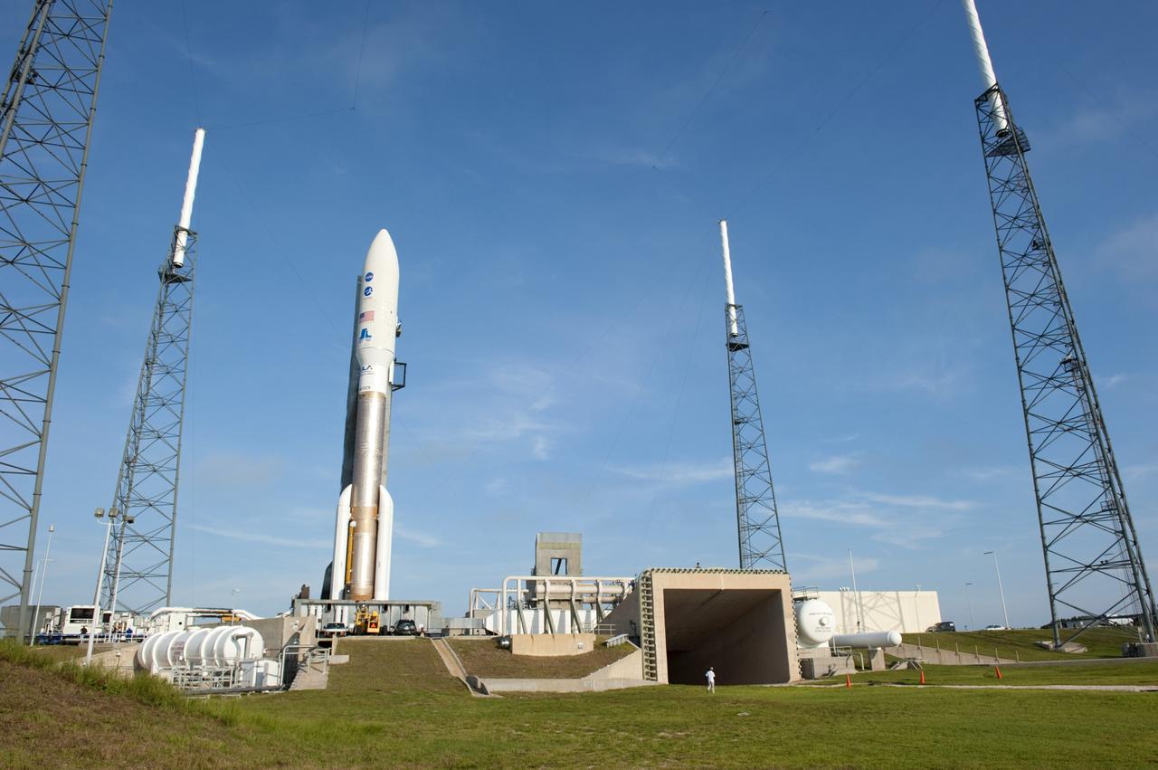
CAPE CANAVERAL, Fla. -- NASA's Juno spacecraft, enclosed in its payload fairing atop a United Launch Alliance Atlas V-551 launch vehicle, is nestled between the towers of the lightning protection system beside the exhaust duct on the launch pad at Space Launch Complex 41 on Cape Canaveral Air Force Station in Florida. Liftoff is planned during a launch window which extends from 11:34 a.m. to 12:43 p.m. EDT on Aug. 5. The solar-powered spacecraft will orbit Jupiter's poles 33 times to find out more about the gas giant's origins, structure, atmosphere and magnetosphere and investigate the existence of a solid planetary core. NASA's Jet Propulsion Laboratory, Pasadena, Calif., manages the Juno mission for the principal investigator, Scott Bolton, of Southwest Research Institute in San Antonio. The Juno mission is part of the New Frontiers Program managed at NASA's Marshall Space Flight Center in Huntsville, Ala. Lockheed Martin Space Systems, Denver, built the spacecraft. Launch management for the mission is the responsibility of NASA's Launch Services Program at the Kennedy Space Center in Florida. For more information, visit www.nasa.gov/juno. Photo credit: NASA/Kim Shiflett

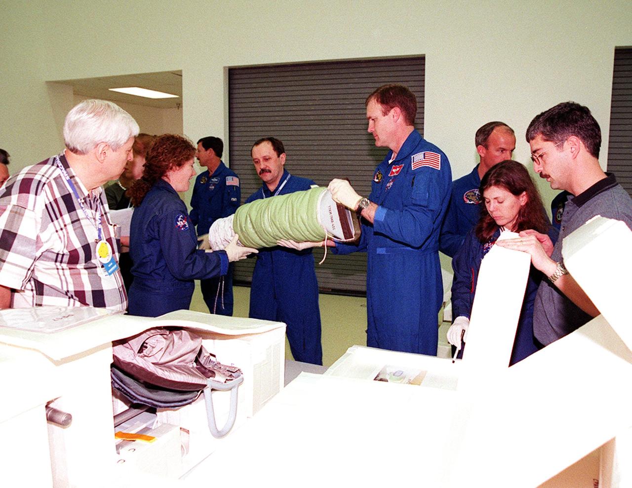
KENNEDY SPACE CENTER, FLA. -- Members of the STS-101 crew take part in Crew Equipment Interface Test (CEIT) activities at SPACEHAB, in Cape Canaveral, Fla., where they are learning about some of the equipment they will be working with on their mission to the International Space Station. Mission Specialist Susan Helms holds one component while Commander James Halsell and Mission Specialist Yuri Usachev look on, and Mission Specialists Mary Ellen Weber and Jeffrey Williams discuss another. Also taking part in the CEIT are Pilot Scott Horowitz and Mission Specialist James Voss. The green component on the table is an air duct to be installed in the Russian module Zarya to improve ventilation. The STS-101 crew will be responsible for preparing the Space Station for the arrival of the Zvezda Service Module, expected to be launched by Russia in July 2000. Also, the crew will conduct one space walk to perform maintenance on the Space Station and deliver logistics and supplies. This will be the third assembly flight for the Space Station. STS-101 is scheduled to launch no earlier than April 13 from Launch Pad 39A
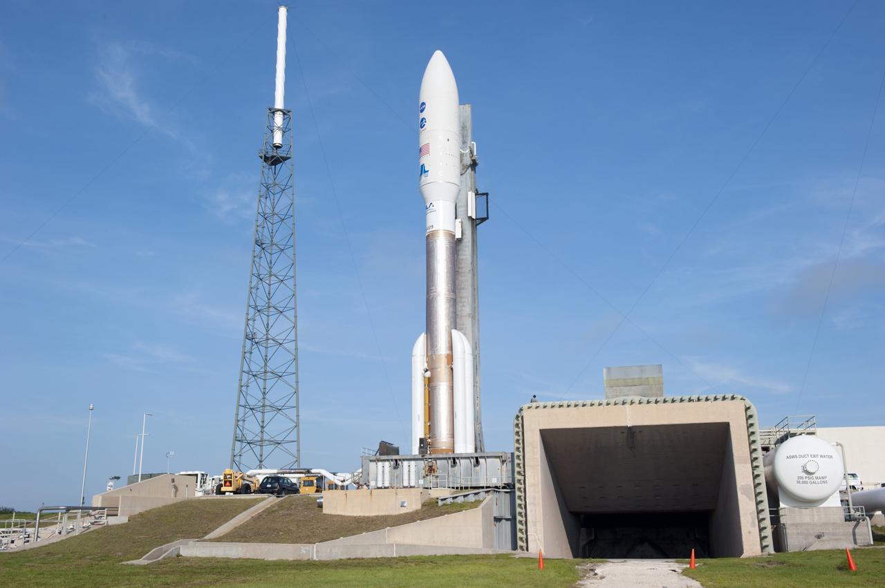
CAPE CANAVERAL, Fla. -- On Cape Canaveral Air Force Station in Florida, the 197-foot-tall United Launch Alliance Atlas V-551 launch vehicle is in position beside the exhaust duct on the launch pad at Space Launch Complex 41. Atop the rocket is NASA's Juno spacecraft, enclosed in its payload fairing. Liftoff is planned during a launch window which extends from 11:34 a.m. to 12:43 p.m. EDT on Aug. 5. The solar-powered spacecraft will orbit Jupiter's poles 33 times to find out more about the gas giant's origins, structure, atmosphere and magnetosphere and investigate the existence of a solid planetary core. NASA's Jet Propulsion Laboratory, Pasadena, Calif., manages the Juno mission for the principal investigator, Scott Bolton, of Southwest Research Institute in San Antonio. The Juno mission is part of the New Frontiers Program managed at NASA's Marshall Space Flight Center in Huntsville, Ala. Lockheed Martin Space Systems, Denver, built the spacecraft. Launch management for the mission is the responsibility of NASA's Launch Services Program at the Kennedy Space Center in Florida. For more information, visit www.nasa.gov/juno. Photo credit: NASA/Kim Shiflett
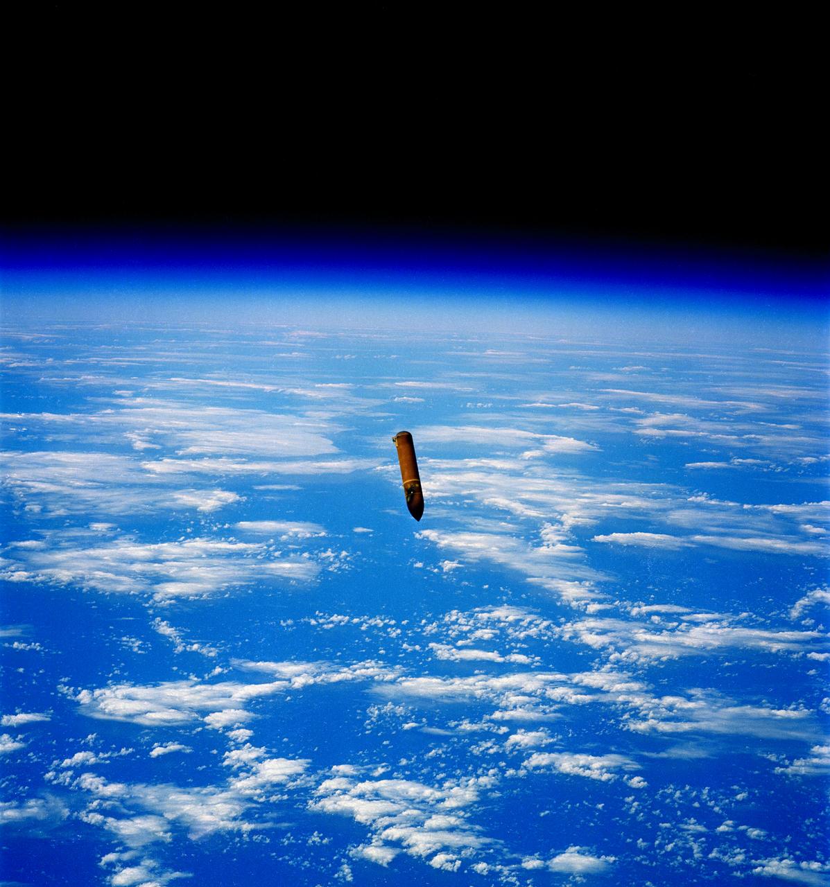
This STS-29 mission onboard photo depicts the External Tank (ET) falling toward the ocean after separation from the Shuttle orbiter Discovery. The giant cylinder, higher than a 15-story building, with a length of 154-feet (47-meters) and a diameter of 27,5-feet (8.4-meters), is the largest single piece of the Space Shuttle. During launch, the ET also acts as a backbone for the orbiter and solid rocket boosters. In separate, internal pressurized tank sections, the ET holds the liquid hydrogen fuel and liquid oxygen oxidizer for the Shuttle's three main engines. During launch, the ET feeds the fuel under pressure through 17-inch (43.2-centimeter) ducts which branch off into smaller lines that feed directly into the main engines. Some 64,000 gallons (242,260 liters) of fuel are consumed by the main engines each minute. Machined from aluminum alloys, the Space Shuttle's ET is the only part of the launch vehicle that currently is not reused. After its 526,000 gallons (1,991,071 liters) of propellants are consumed during the first 8.5 minutes of flight, it is jettisoned from the orbiter and breaks up in the upper atmosphere, its pieces falling into remote ocean waters. The Marshall Space Flight Center was responsible for developing the ET.
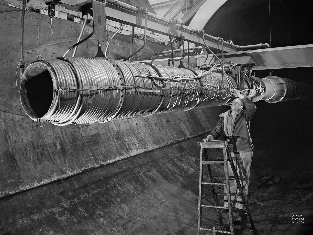
A 20-inch diameter ramjet installed in the Altitude Wind Tunnel at the National Advisory Committee for Aeronautics (NACA) Lewis Flight Propulsion Laboratory. The Altitude Wind Tunnel was used in the 1940s to study early ramjet configurations. Ramjets provide a very simple source of propulsion. They are basically a tube which takes in high-velocity air, ignites it, and then expels the expanded airflow at a significantly higher velocity for thrust. Ramjets are extremely efficient and powerful but can only operate at high speeds. Therefore a turbojet or rocket was needed to launch the vehicle. This NACA-designed 20-inch diameter ramjet was installed in the Altitude Wind Tunnel in May 1945. The ramjet was mounted under a section of wing in the 20-foot diameter test section with conditioned airflow ducted directly to the engine. The mechanic in this photograph was installing instrumentation devices that led to the control room. NACA researchers investigated the ramjet’s overall performance at simulated altitudes up to 47,000 feet. Thrust measurements from these runs were studied in conjunction with drag data obtained during small-scale studies in the laboratory’s small supersonic tunnels. An afterburner was attached to the ramjet during the portions of the test program. The researchers found that an increase in altitude caused a reduction in the engine’s horsepower. They also determined the optimal configurations for the flameholders, which provided the engine’s ignition source.

This is a cutaway illustration of the Space Shuttle external tank (ET) with callouts. The giant cylinder, higher than a 15-story building, with a length of 154-feet (47-meters) and a diameter of 27.5-feet (8.4-meters), is the largest single piece of the Space Shuttle. During launch, the ET also acts as a backbone for the orbiter and solid rocket boosters. Separate pressurized tank sections within the external tank hold the liquid hydrogen fuel and liquid oxygen oxidizer for the Shuttle's three main engines. During launch, the ET feeds the fuel under pressure through 17-inch (43.2-centimeter) ducts that branch off into smaller lines that feed directly into the main engines. The main engines consume 64,000 gallons (242,260 liters) of fuel each minute. Machined from aluminum alloys, the Space Shuttle's external tank is currently the only part of the launch vehicle that is not reused. After its 526,000-gallons (1,991,071 liters) of propellants are consumed during the first 8.5-minutes of flight, it is jettisoned from the orbiter and breaks up in the upper atmosphere, its pieces falling into remote ocean waters. The Marshall Space Flight Center was responsible for developing the ET.
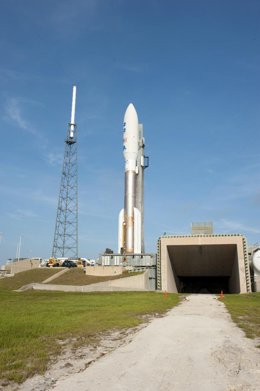
CAPE CANAVERAL, Fla. -- On Cape Canaveral Air Force Station in Florida, the 197-foot-tall United Launch Alliance Atlas V-551 launch vehicle is in position beside the exhaust duct on the launch pad at Space Launch Complex 41. Atop the rocket is NASA's Juno spacecraft, enclosed in its payload fairing. Liftoff is planned during a launch window which extends from 11:34 a.m. to 12:43 p.m. EDT on Aug. 5. The solar-powered spacecraft will orbit Jupiter's poles 33 times to find out more about the gas giant's origins, structure, atmosphere and magnetosphere and investigate the existence of a solid planetary core. NASA's Jet Propulsion Laboratory, Pasadena, Calif., manages the Juno mission for the principal investigator, Scott Bolton, of Southwest Research Institute in San Antonio. The Juno mission is part of the New Frontiers Program managed at NASA's Marshall Space Flight Center in Huntsville, Ala. Lockheed Martin Space Systems, Denver, built the spacecraft. Launch management for the mission is the responsibility of NASA's Launch Services Program at the Kennedy Space Center in Florida. For more information, visit www.nasa.gov/juno. Photo credit: NASA/Kim Shiflett
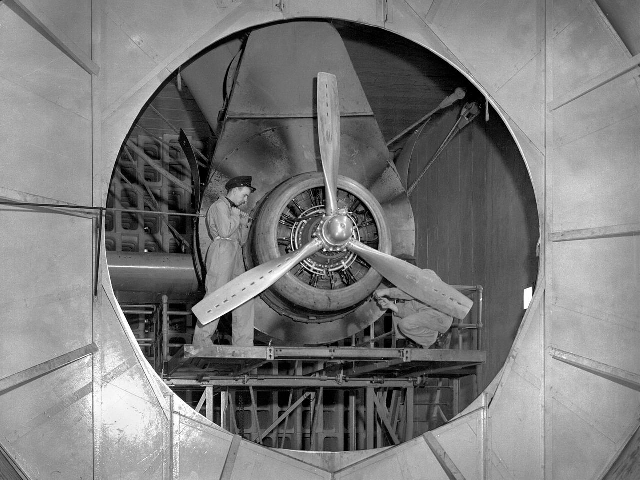
A Wright Aeronautical R–2600 Cyclone piston engine installed in the Engine Propeller Research Building, or Prop House, at the National Advisory Committee for Aeronautics (NACA) Aircraft Engine Research Laboratory. The R–2600 was among the most powerful engines that emerged during World War II. The engine, which was developed for commercial applications in 1939, was used to power the North American B–25 bomber and several other midsize military aircraft. The higher altitudes required by the military caused problems with the engine's cooling and fuel systems. The military requested that the Aircraft Engine Research Laboratory analyze the performance of the R–2600, improve its cooling system, and reduce engine knock. The NACA researchers subjected the engine to numerous tests in its Prop House. The R–2600 was the subject of the laboratory's first technical report, which was written by members of the Fuels and Lubricants Division. The Prop House contained soundproof test cells in which piston engines and propellers were mounted and operated at high powers. Electrically driven fans drew air through ducts to create a stream of cooling air over the engines. Researchers tested the performance of fuels, turbochargers, water-injection and cooling systems here during World War II. The facility was also investigated a captured German V–I buzz bomb during the war.
Aerial view of Gasdynamics facility in 1964 and the 20 inch helium tunnel Part of the Thermal Protection Laboratory used to research materials for heat shield applications and for aerodynamic heating and materials studies of vehicles in planetary atmospheres. This laboratory is comprised of five separate facilities: an Aerodynamic Heating Tunnel, a Heat Transfer Tunnel, two Supersonic Turbulent Ducts, and a High-Power CO2 Gasdynamic Laser. All these facilities are driven by arc-heaters, with the exception of the large, combustion-type laser. The arc-heated facilities are powered by a 20 Megawatt DC power supply. Their effluent gas stream (test gases; Air, N2, He, CO2 and mixtures; flow rates from 0.05 to 5.0 lbs/sec) discharges into a five-stage stream-ejector-driven vacuum system. The vacuum system and power supply are common to the test faciities in building N-238. All of the facilities have high pressure water available at flow rates up to 4, 000 gals/min. The data obtained from these facilities are recorded on magnetic tape or oscillographs. All forms of data can be handled whether from thermo-couples, pressure cells, pyrometers, or radiometers, etc. in addition, closed circuit T. V. monitors and various film cameras are available. (operational since 1962)
KENNEDY SPACE CENTER, FLA. -- Members of the STS-101 crew take part in Crew Equipment Interface Test (CEIT) activities at SPACEHAB, in Cape Canaveral, Fla., where they are learning about some of the equipment they will be working with on their mission to the International Space Station. Mission Specialist Susan Helms holds one component while Commander James Halsell and Mission Specialist Yuri Usachev look on, and Mission Specialists Mary Ellen Weber and Jeffrey Williams discuss another. Also taking part in the CEIT are Pilot Scott Horowitz and Mission Specialist James Voss. The green component on the table is an air duct to be installed in the Russian module Zarya to improve ventilation. The STS-101 crew will be responsible for preparing the Space Station for the arrival of the Zvezda Service Module, expected to be launched by Russia in July 2000. Also, the crew will conduct one space walk to perform maintenance on the Space Station and deliver logistics and supplies. This will be the third assembly flight for the Space Station. STS-101 is scheduled to launch no earlier than April 13 from Launch Pad 39A
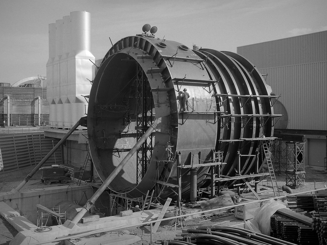
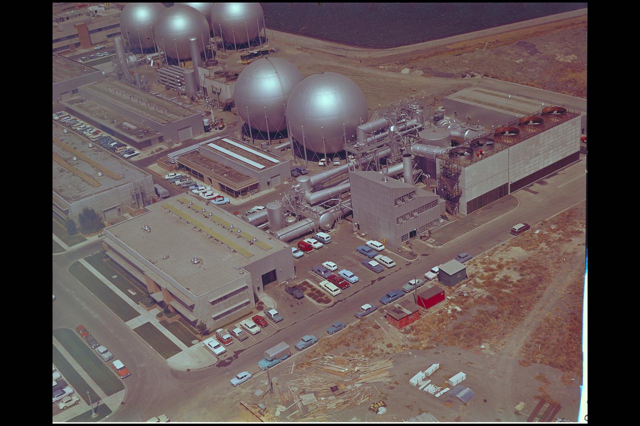
The 50-foot diameter primary cooler for the new Propulsion Systems Laboratory No. 3 and 4 facility constructed at the National Aeronautics and Space Administration (NASA) Lewis Research Center. In 1968, 20 years after planning began for the original Propulsion Systems Laboratory test chambers, No. 1 and 2, NASA Lewis began preparations to add two additional and more powerful chambers. The move coincided with the center’s renewed focus on aeronautics in 1966. The new 40-foot long and 24-foot diameter chambers were capable of testing engines twice as powerful any then in existence and significantly larger than those in the original two test chambers. After exiting the engine nozzle, the hot exhaust air passed through a 17-foot diameter water exhaust duct and the 50-foot diameter primary cooler. Twenty-seven hundred water-filled tubes inside the cooler reduced the temperature of the air flow as it passed between the tubes from 3000 to 600 °F. A spray cooler further reduced the temperature of the gases to 150 °F before they were sent to the Central Air Building. Excavations for the new facility were completed by October 1967, and the shell of the building was completed a year later. In September 1968, work began on the new test chambers and associated infrastructure. Construction was completed in late 1972, and the first test was scheduled for February 1973.
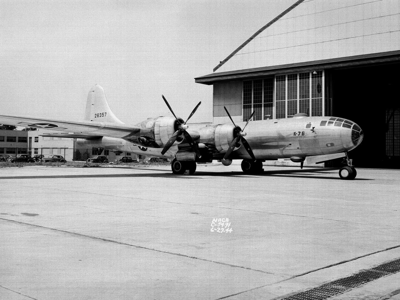
A Boeing B–29 Superfortress at the National Advisory Committee for Aeronautics (NACA) Aircraft Engine Research Laboratory in Cleveland, Ohio. The B–29 was the Army Air Forces’ deadliest weapon during the latter portion of World War II. The aircraft was significantly larger than previous bombers but could fly faster and higher. The B–29 was intended to soar above anti-aircraft fire and make pinpoint drops onto strategic targets. The bomber was forced to carry 20,000 pounds more armament than it was designed for. The extra weight pushed the B–29’s four powerful Wright R–3350 engines to their operating limits. The over-heating of the engines proved to be a dangerous problem. The military asked the NACA to tackle the issue. Full-scale engine tests on a R–3350 engine in the Prop House demonstrated that a NACA-designed impeller increased the flow rate of the fuel injection system. Altitude Wind Tunnel studies of the engine led to the reshaping of cowling inlet and outlet to improve airflow and reduce drag. Single-cylinder studies on valve failures were resolved by a slight extension of the cylinder head, and the Engine Research Building researchers combated uneven heating with a new fuel injection system. The modifications were then tried out on an actual B–29. The bomber arrived in Cleveland on June 22, 1944. The new injection impeller, ducted head baffles and instrumentation were installed on the bomber’s two left wing engines. Eleven test flights were flown over the next month with military pilots at the helm. Overall the flight tests corroborated the wind tunnel and test stand studies.

Title: W-8 Fan Acoustic Casing Treatment Test on the Source Diagnostic Test Rotor Alone Hardware Program: Advanced Air Vehicles Program (AAVP) Project: Advanced Air Transport Technology (AATT) Sub-project: Aircraft Noise Reduction (ANR) Weekly Highlight: · Acoustic Casing Treatment Testing Completed in the W-8 Single Stage Axial Compressor Facility: Testing of Acoustic Casing Treatments on the Source Diagnostic Test (SDT) rotor alone hardware which had begun in early January was completed on Thursday, February 16th. Four different over-the-rotor acoustic casing treatment concepts were tested along with two baseline configurations. Testing included steady-aerodynamic measurements of fan performance, hotfilm turbulence measurements, and inlet acoustic measurements with an in-duct array. These measurements will be used to assess the aerodynamic and acoustic impact of fan acoustic casing treatments on a high bypass ratio fan at TRL 3. This test was the last of 3 planned tests of potential over-the-rotor acoustic casing treatments. The first treatment test was completed in the Normal Incidence Tube (NIT) at Langley Research Center (LaRC) in Fall 2015 and the second was completed on the Advanced Noise Control Fan (ANCF) in the Aero-Acoustic Propulsion Laboratory (AAPL) in Winter 2016. This work is supported by the Aircraft Noise Reduction (ANR) subproject of the Advanced Air Transport Technology (AATT) Project. (POC: LTV/ Rick Bozak 3-5160)
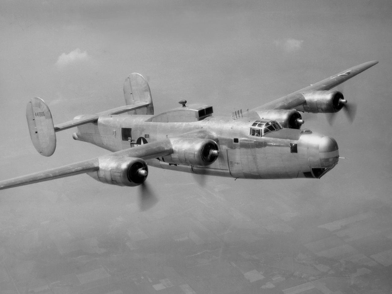
A Consolidated B-25M Liberator modified for icing research by the National Advisory Committee for Aeronautics (NACA) Lewis Flight Propulsion Laboratory. NACA Lewis performed a limited amount of icing research during World War II, but the program expanded significantly in 1946. The accumulation of ice on aircraft was a continual problem. The ice formations could result in extra weight, aerodynamic penalties, and blockage engine inlets. Although the Lewis icing researchers utilized numerous aircraft, the program’s two workhorses were the B-24M Liberator, seen here, and a North American XB-25E Mitchell. The Consolidated Aircraft Company created the four-engine bomber in the early 1940s. During World War II the bomber was employed on long-duration bombing missions in both Europe and the Pacific. Production of the B-24M version did not begin until October 1944 with the end of the war in Europe approaching. This resulted in scores of unneeded bombers when hostilities ended. This B-24M arrived at the NACA Lewis laboratory in November 1945. At Lewis the B-24M was repeatedly modified to study ice accretion on aircraft components. Researchers analyzed different anti-icing and deicing strategies and gathered statistical ice measurement data. The B-24M was also used to study ice buildup on jet engines. A General Electric I-16 engine was installed in the aircraft’s waist compartment with an air scoop on the top of the aircraft to duct air to the engine. Water spray nozzles inside the aircraft were employed to simulate icing conditions at the turbojet’s inlet.
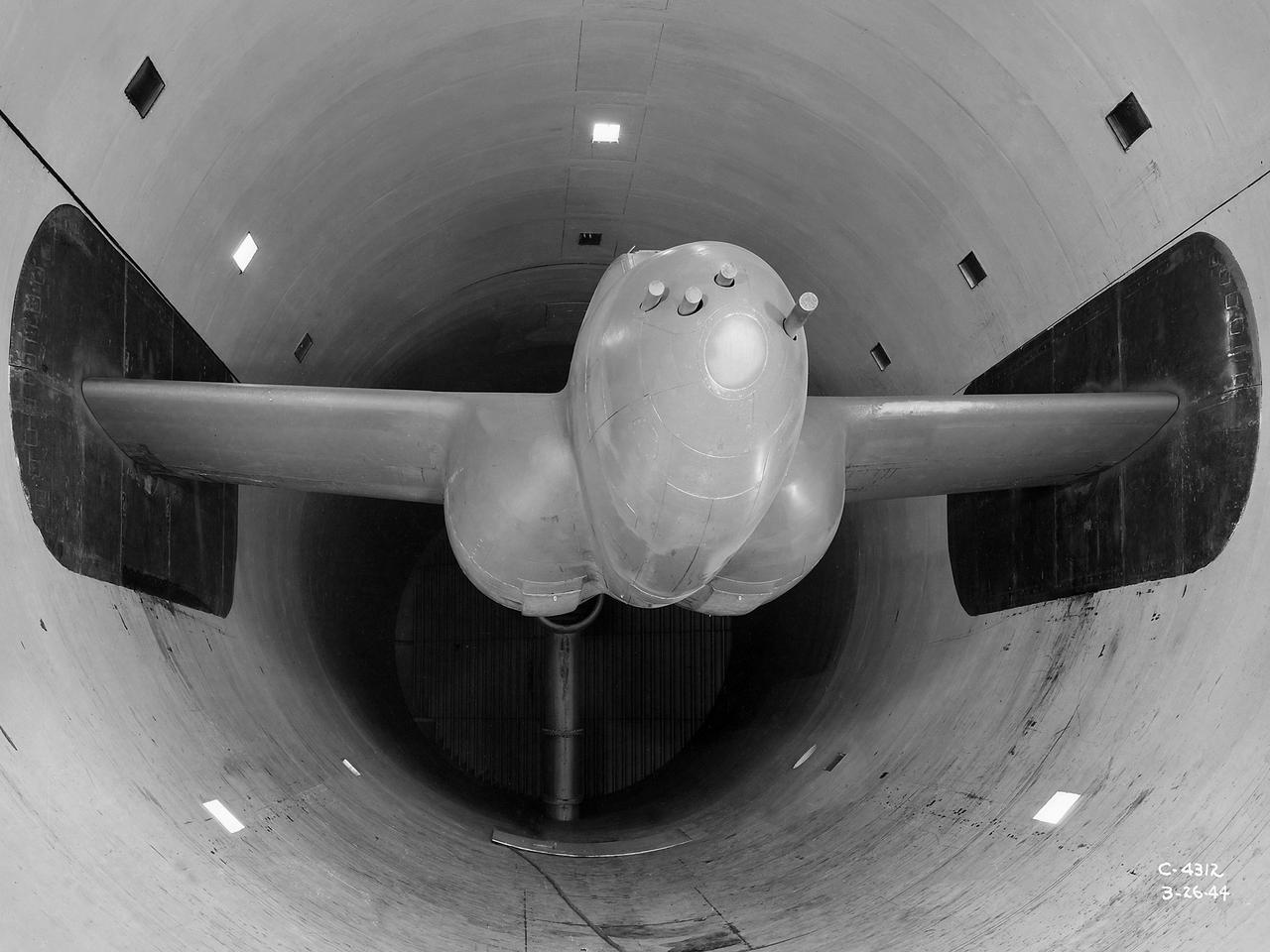
The Altitude Wind Tunnel (AWT) was the National Advisory Committee for Aeronautics (NACA) Aircraft Engine Research Laboratory’s largest and most important test facility in the 1940s. The AWT employed massive cooling and exhaust systems to simulate conditions found at high altitudes. The facility was originally designed to test large piston engines in a simulated flight environment. The introduction of the turbojet during the tunnel’s construction, however, changed the facility’s focus before it became operational. Its first test program was a study of the Bell YP–59A Airacomet and its General Electric I–16 turbojets. The Airacomet was the United States’ first attempt to build a jet aircraft. 1600-horsepower centrifugal engines based on an early design by British engineer Frank Whittle were incorporated into an existing Bell airframe. In October 1942 the Airacomet was secretly test flown in the California desert. The aircraft’s performance was limited, however, and the NACA was asked to study the engines in the AWT. The wind tunnel’s 20-foot-diameter test section was large enough to accommodate entire aircraft with its wing tips and tail removed. The I-16 engines were studied exhaustively in early 1944. They first analyzed the engines in their original configuration and then implemented a boundary layer removal duct, a new nacelle inlet, and new cooling seals. Tests of the modified version showed that the improved distribution of airflow increased the I–16’s performance by 25 percent. The Airacomet never overcame some of its inherent design issues, but the AWT went on to study nearly every emerging US turbojet model during the next decade.
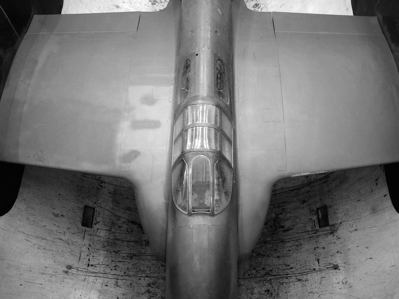
The secret test of the Bell YP–59A Airacomet in the spring of 1944 was the first investigation in the National Advisory Committee for Aeronautics (NACA) Aircraft Engine Research Laboratory’s new Altitude Wind Tunnel (AWT). The Airacomet, powered by two General Electric I–A centrifugal turbojets, was the first US jet aircraft. The Airacomet’s 290-miles per hour speed, however, was dwarfed by the German Messerschmitt Me-262 Schwalbe’s 540 miles per hour. In 1941 and 1942 General Electric built the first US jet engines based on technical drawings from British engineer Frank Whittle. Bell Aircraft was contracted to produce an airframe to incorporate the new engines. The result was the Bell XP–59A Airacomet. The aircraft made its first flight over Muroc Lake, California, on October 2, 1942. The aircraft continued to struggle over the next year and the NACA was asked to test it in the new AWT. A Bell YP–59A was flown from the Bell plant in Buffalo to Cleveland by Bob Stanley, who had piloted the first successful flight of the XP–59A at Muroc in 1942. The wing tips and tail were cut from the aircraft so that it would fit into the AWT’s test section. The study first analyzed the engines in their original configuration and then implemented a boundary layer removal duct, a new nacelle inlet, and new cooling seals. Tests of the modified version showed that the improved airflow distribution increased the I–16’s performance by 25 percent. Despite the improved speed, the aircraft was not stable enough to be used in combat, and the design was soon abandoned.
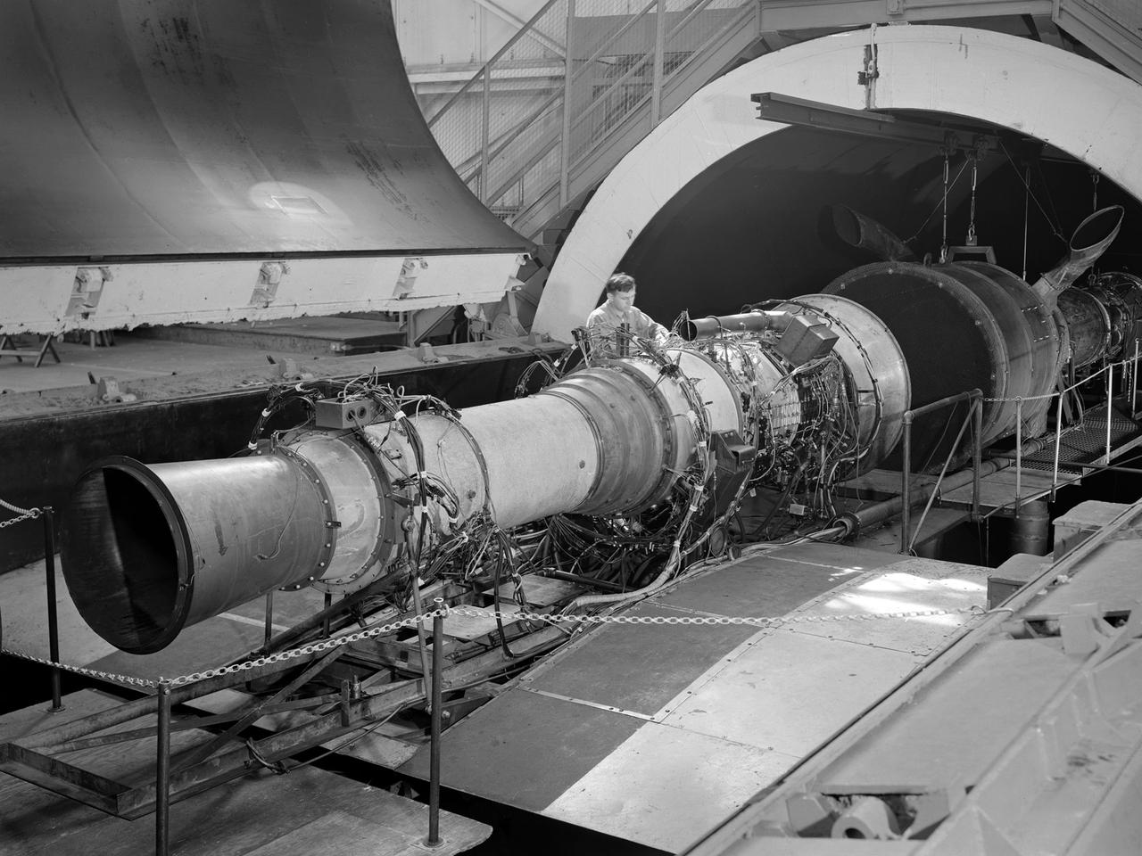
A Rolls Royce Avon RA-14 engine was tested in the Altitude Wind Tunnel at the National Advisory Committee for Aeronautics’ (NACA) Lewis Flight Propulsion Laboratory. The Avon RA-14 engine was a 16-stage axial-flow compressor turbojet capable of producing 9,500 pounds of thrust. The Avon replaced Rolls Royce’s successful Nene engine in 1950 and remained in service until 1974. It was one of several British engines studied in the tunnel during the 1950s. The Altitude Wind Tunnel went through a series of modifications in 1951 to increase its capabilities. An annex was attached to the Exhauster Building to house three new Ingersoll-Rand compressors. The wooden blades on the tunnel’s 31-foot diameter fan were replaced, a pump house and exhaust cooler were constructed underneath the tunnel, and two new cells were added to the cooling tower. The modified wind tunnel continued to analyze jet engines in the 1950s, although the engines, like the RA-14 seen here, were much more powerful than those studied several years before. Lewis researchers studied the RA-14 turbojet engine in the Altitude Wind Tunnel for 11 months in 1956. The engine was mounted on a stand capable of gauging engine thrust, and the tunnel’s air was ducted to the engine through a venturi and bellmouth inlet, seen in this photograph. The initial studies established the engine’s performance characteristics with a fixed-area nozzle and its acceleration characteristics. The researchers also used the tunnel to investigate windmilling of the compressor blades, restarting at high altitudes, and the engine’s performance limits at altitude.
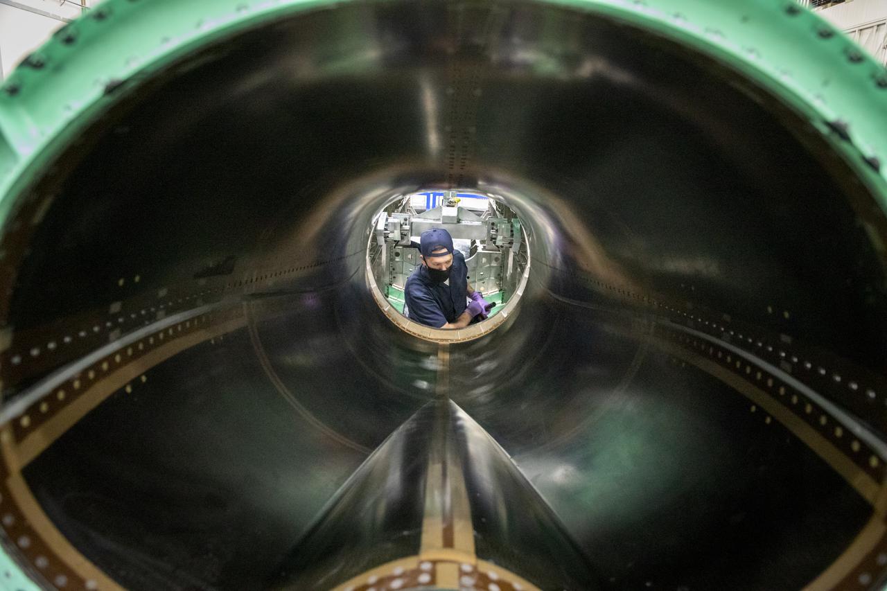
A technician is working on the engine inlet of NASA’s X-59 Quiet Supersonic Technology (QueSST) aircraft at Lockheed Martin’s Skunk Works facility in Palmdale, California.
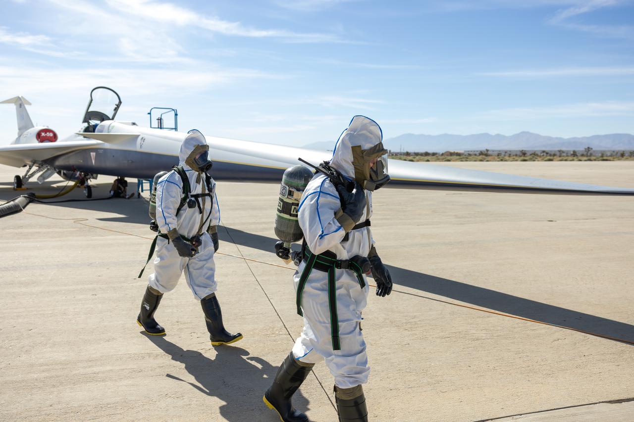
Maintainers perform a hydrazine safety check on NASA’s quiet supersonic X-59 aircraft at U.S. Air Force Plant 42 in Palmdale, California, on Aug. 18, 2025. Hydrazine is a highly toxic chemical, but it serves as a critical backup to restart the engine in flight, if necessary, which is one of several safety features being validated ahead of the aircraft’s first flight.
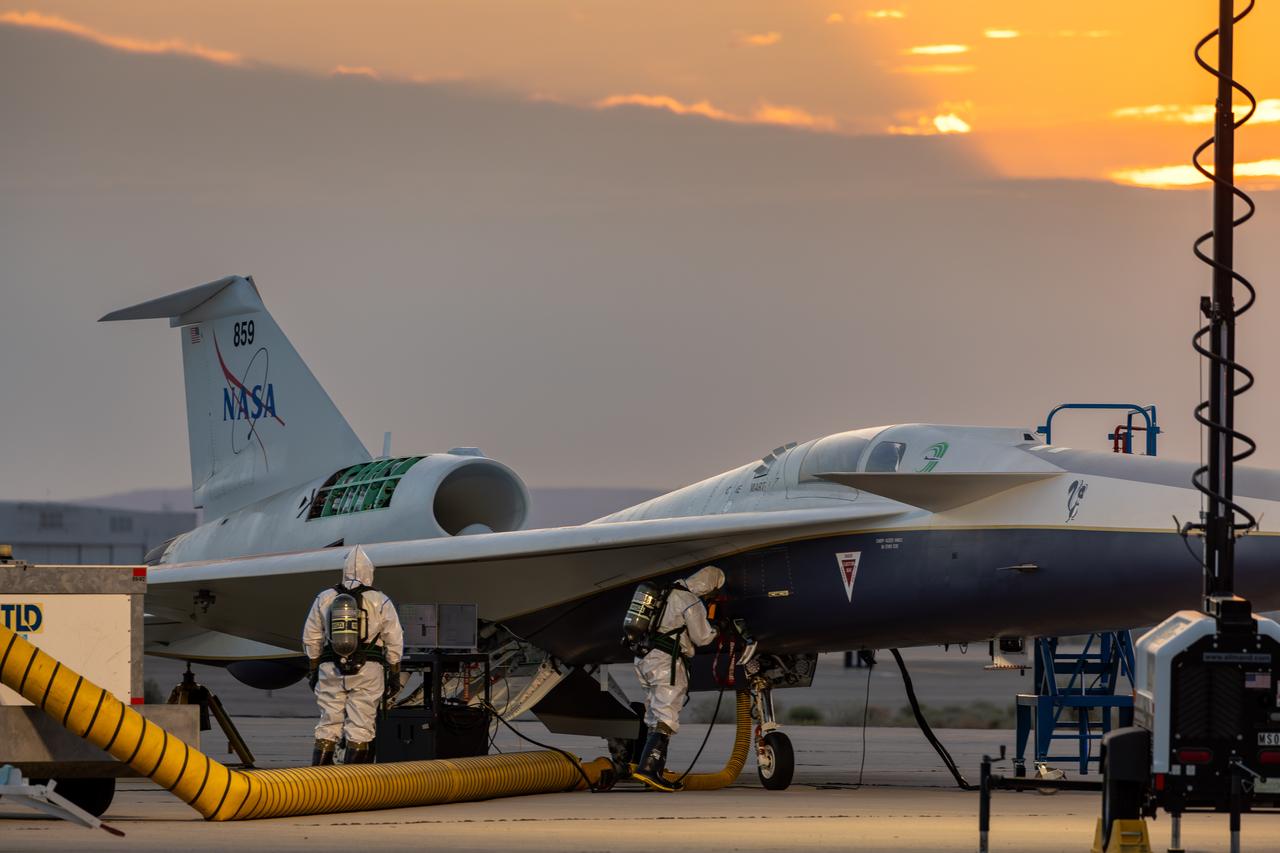
Maintainers perform a hydrazine safety check on the agency’s quiet supersonic X-59 aircraft at U.S. Air Force Plant 42 in Palmdale, California, on Aug. 18, 2025. Hydrazine is a highly toxic chemical, but it serves as a critical backup to restart the engine in flight, if necessary, and is one of several safety features being validated ahead of the aircraft’s first flight.
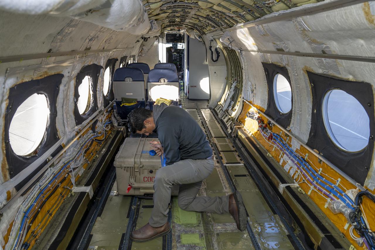
Jose “Manny” Rodriguez, technical engineer at NASA’s Armstrong Flight Research Center in Edwards, California, secures a trunk onboard the G-IV aircraft on March 18, 2025. As the newest member of NASA Armstrong’s airborne science fleet, the G-IV was sent to Avenger Aerospace Solutions in Cartersville, Georgia, for modifications that will optimize the G-IV’s performance as a research aircraft.

NASA employees Broderic J. Gonzalez, left, and David W. Shank, right, install pieces of a 7-foot wing model in preparation for testing in the 14-by-22-Foot Subsonic Wind Tunnel at NASA's Langley Research Center in Hampton, Virginia, in May 2025. The lessons learned from this testing will be shared with the public to support advanced air mobility aircraft development.