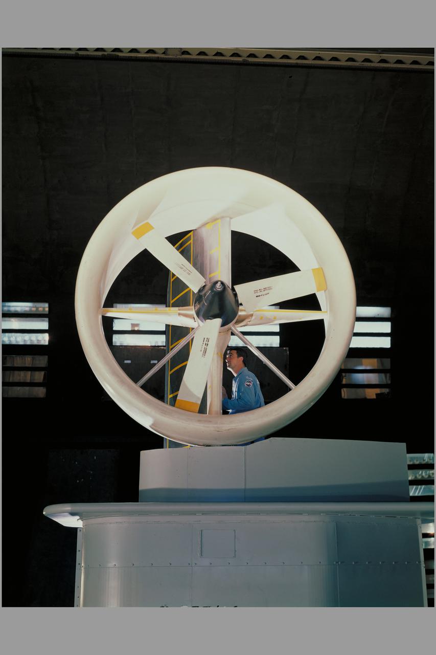
Tandem dual ducted fan mounted on ground plane on varriable height struts, 3/4 front view
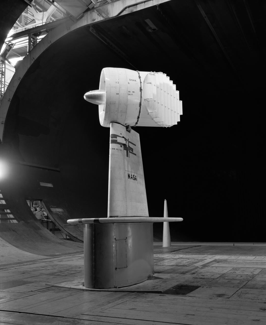
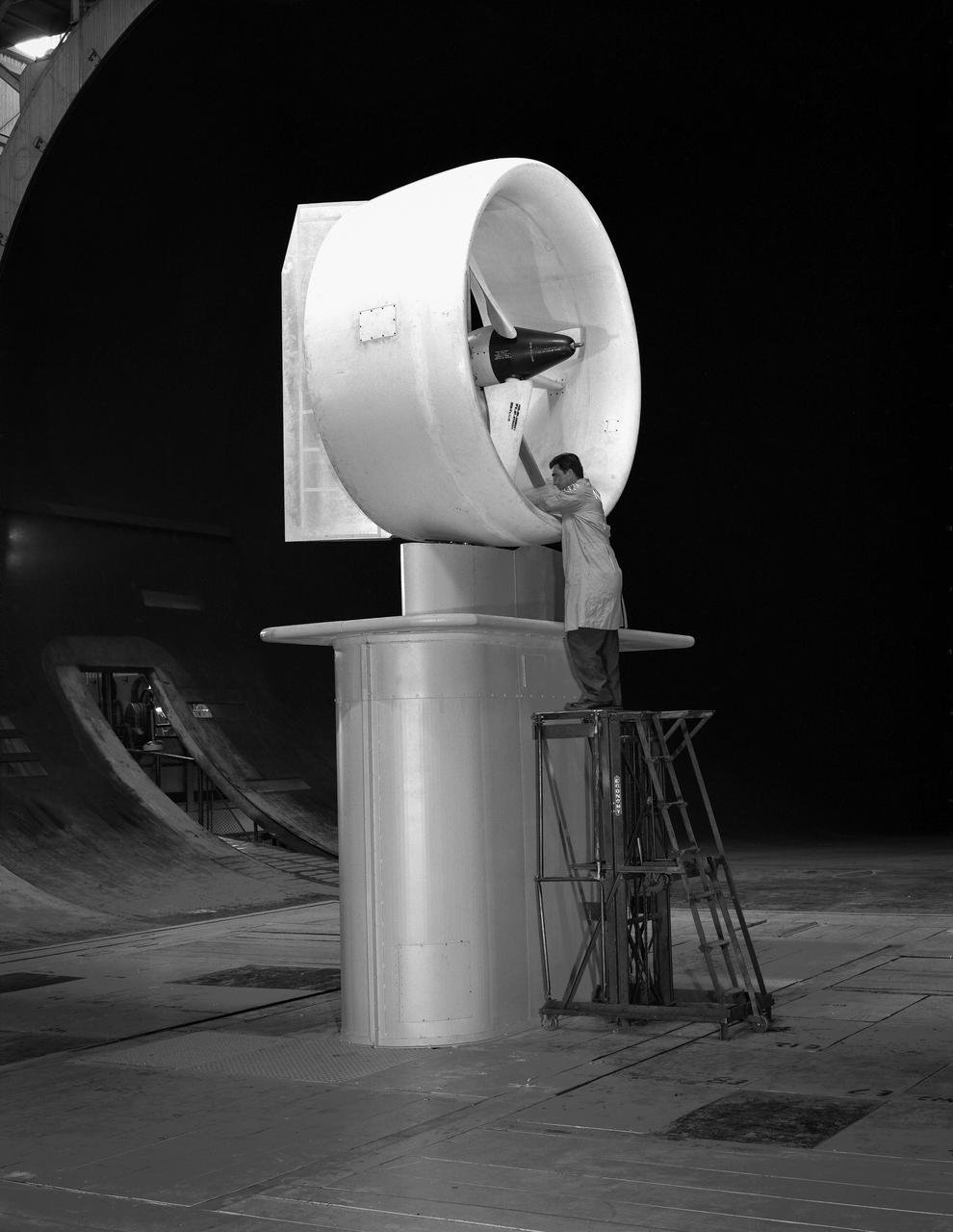
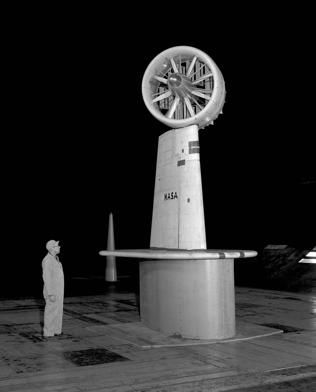
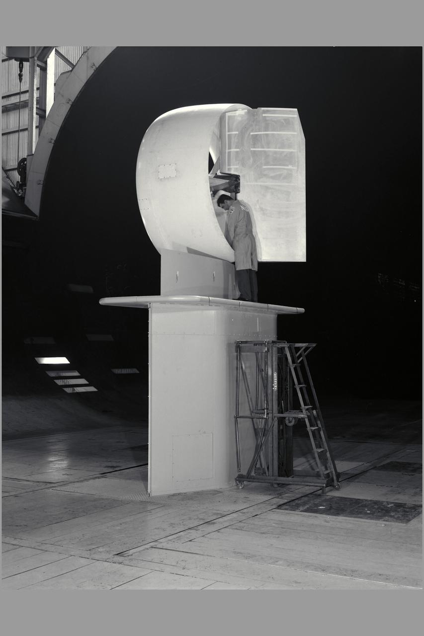
3/4 front view of Ducted fan model with 40 deg. exit vane cascade, semi span model.
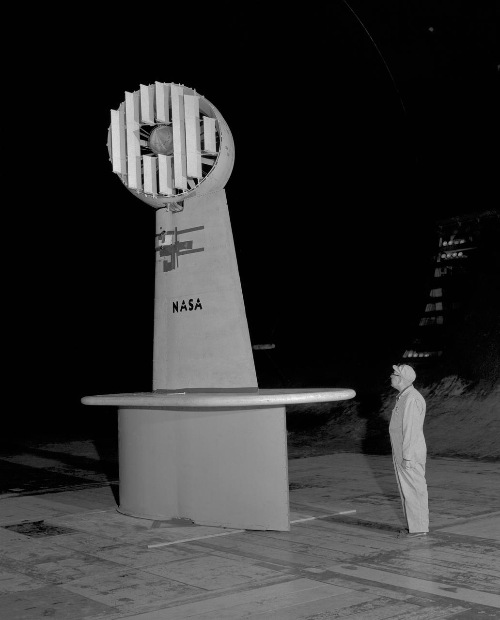
Wind Tunnel investigation of ducted fan though 180 deg angle of attack. 3/4 front view of Doak ducted fan, semi-span model with tufts.
3/4 rear view of ducted fan model with cascade exit vane in Ames 40x80 foot wind tunnel, with Tom Seymore, mechanic for Ames.
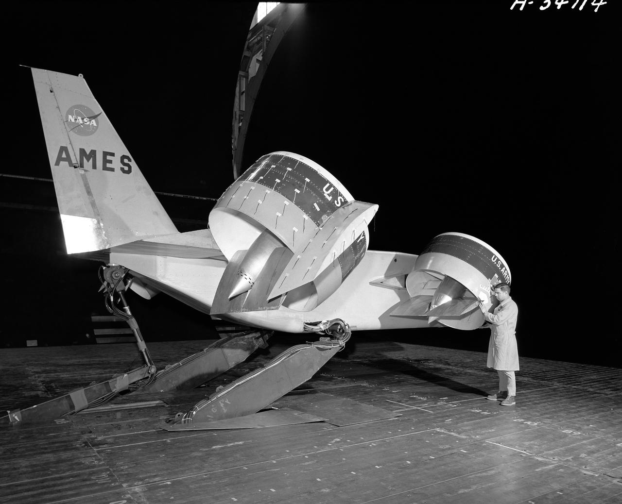
Bell X-22A full scale, Model-C ducted fan with semi-span mount. Duct at 90 degrees with Chuck Greco.
Tandem dual ducted fan mounted on ground plate. 3/4 rear view. Testing for recirculation decrease in performance of lift fans varies with ground effect.
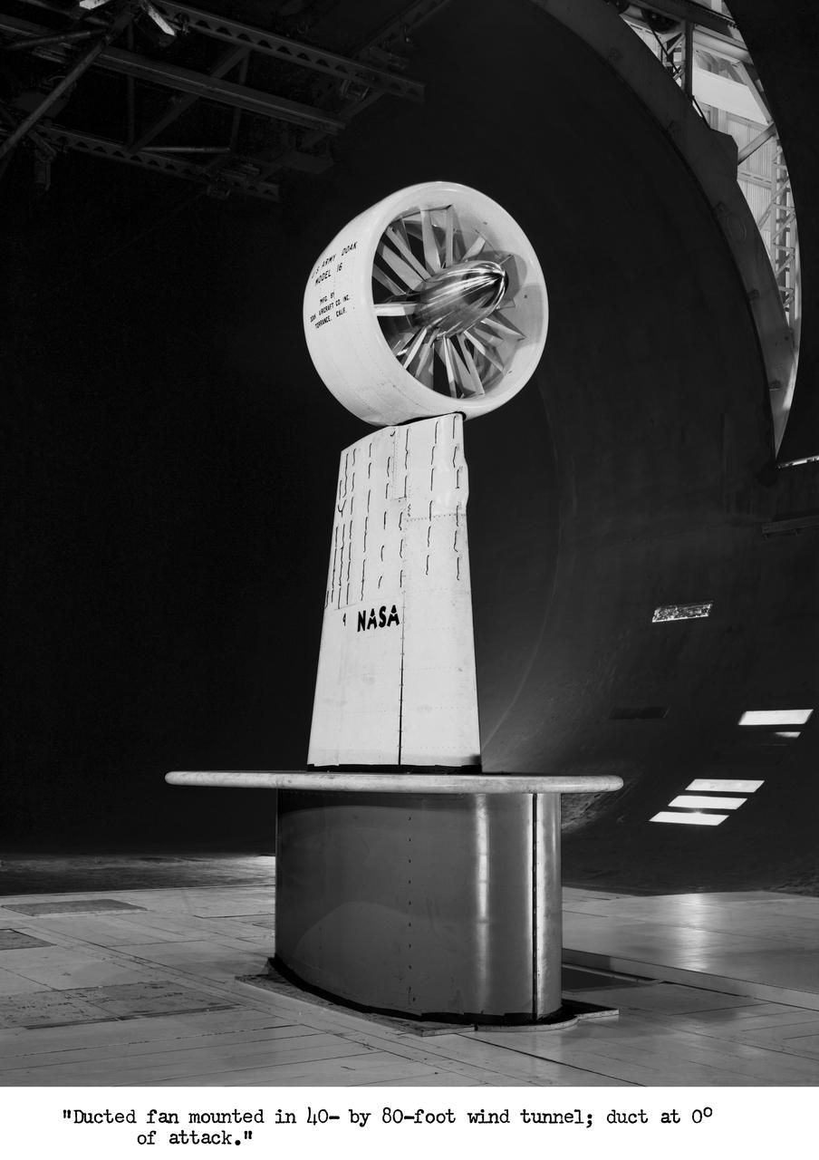
3/4 front view with cascade exit vane in Ames 40x80 foot wind tunnel, with Tom Seymore, mechanic for Ames.
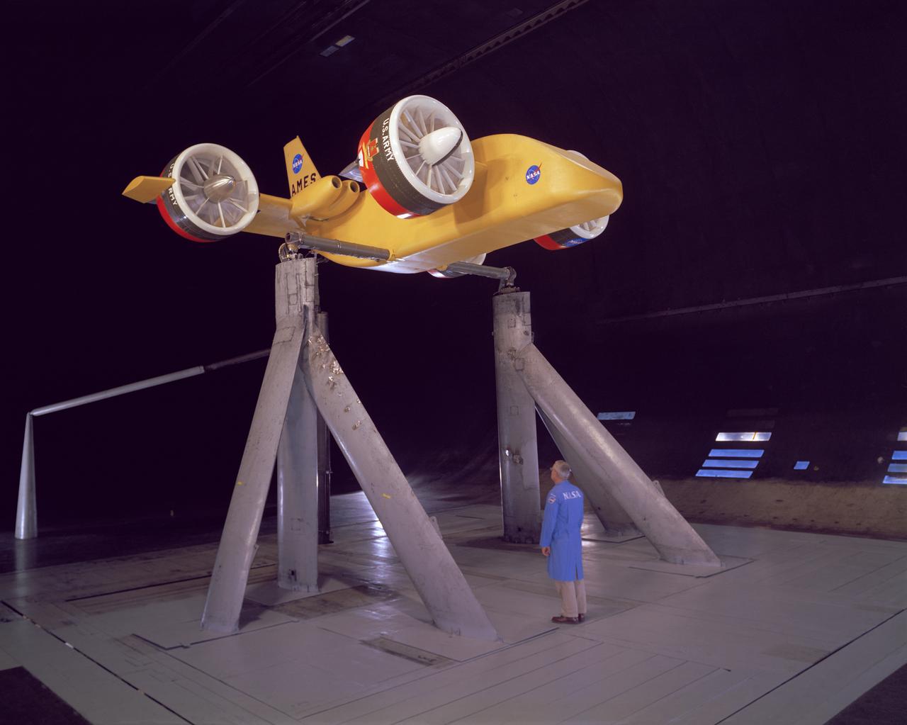
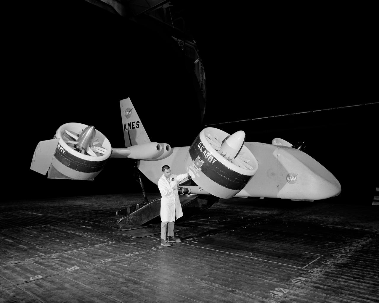
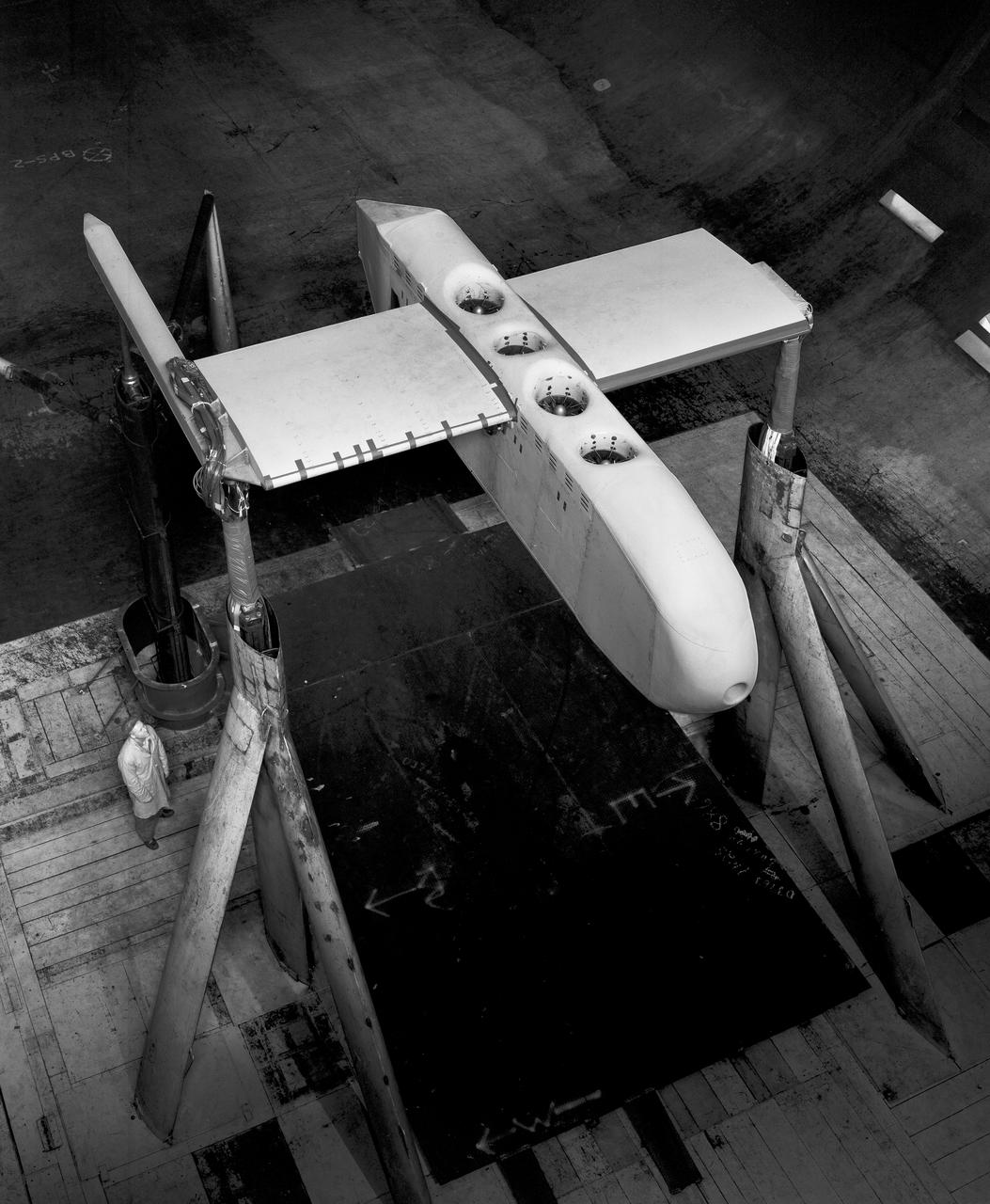
3/4 front view from below, showing Pods and Fan Rotating. March A. Zeiger standing in front. Tandem Dual Ducted Fan V/STOL Model in Ames 40x80 foot Wind Tunnel
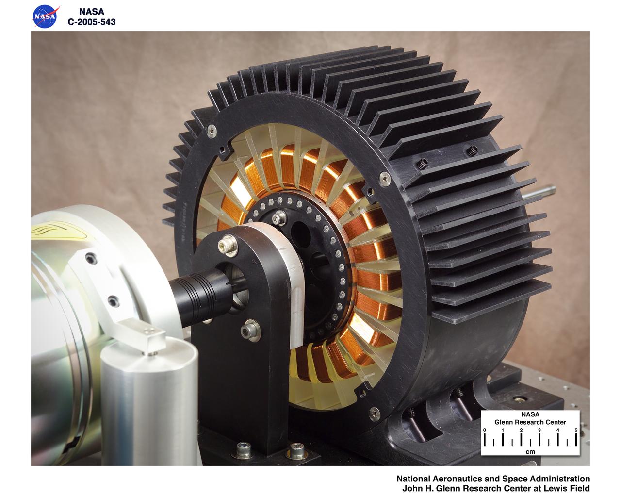
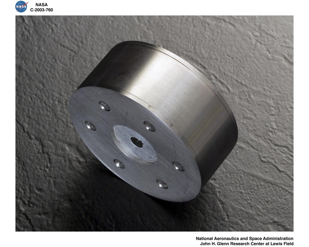
Levitated Ducted Fan (LDF) in the lab
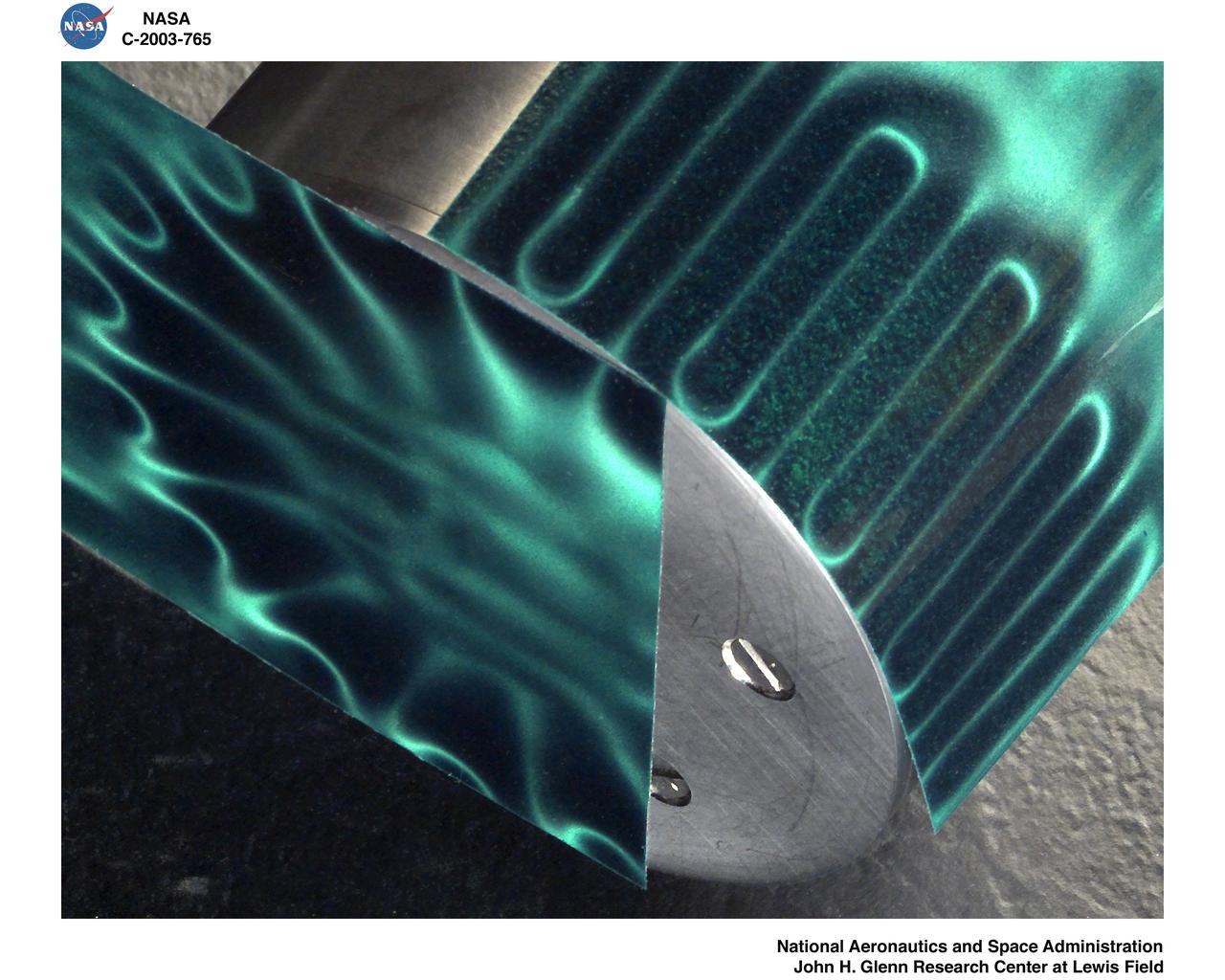
LEVITATED DUCTED FAN TEST ROTOR
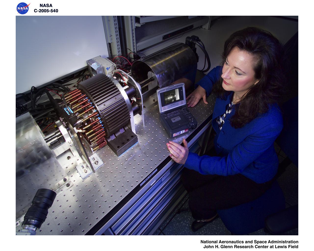
Levitated Ducted Fan (LDF) in the lab
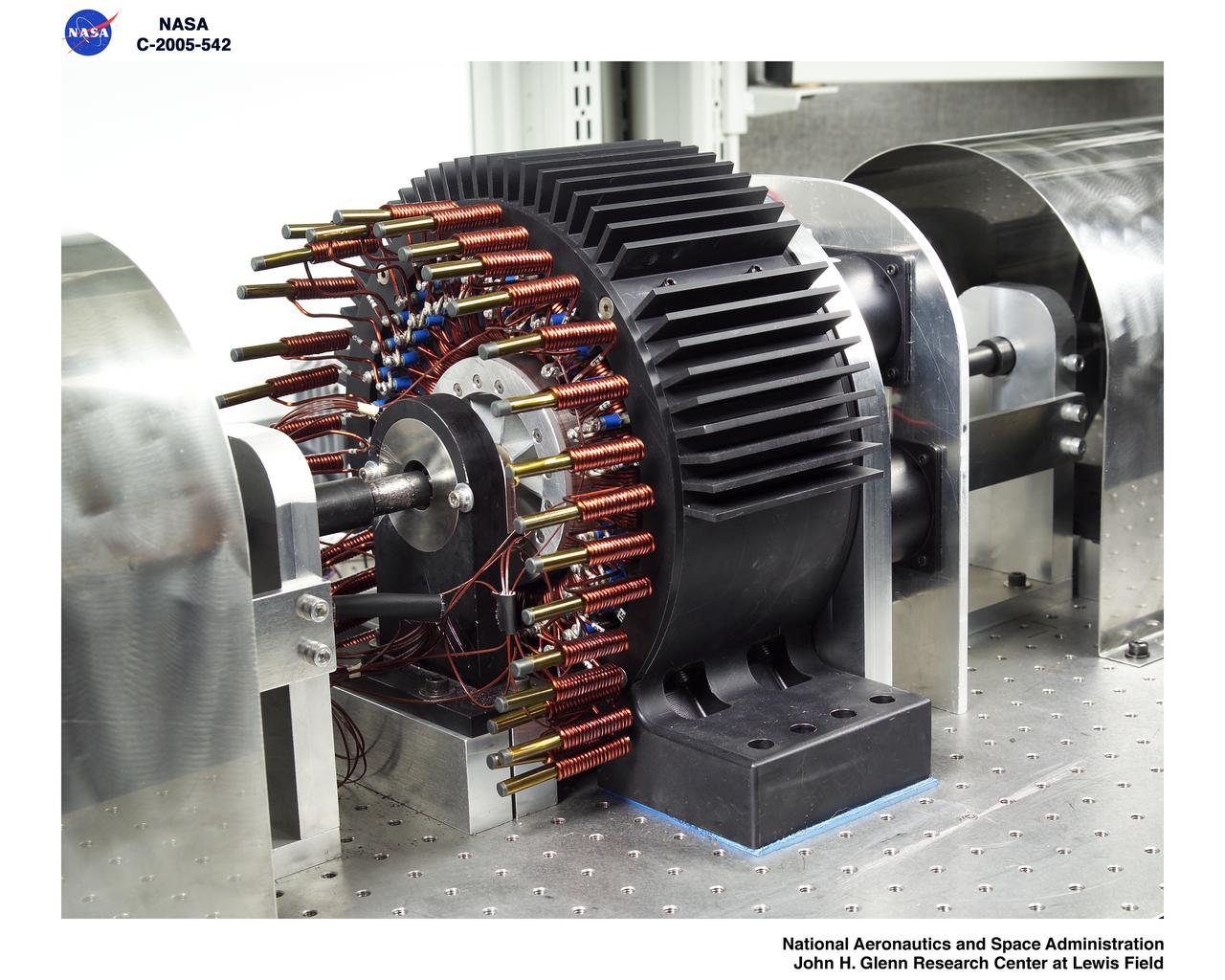
Levitated Ducted Fan (LDF) in the lab
LEVITATED DUCTED FAN TEST ROTOR

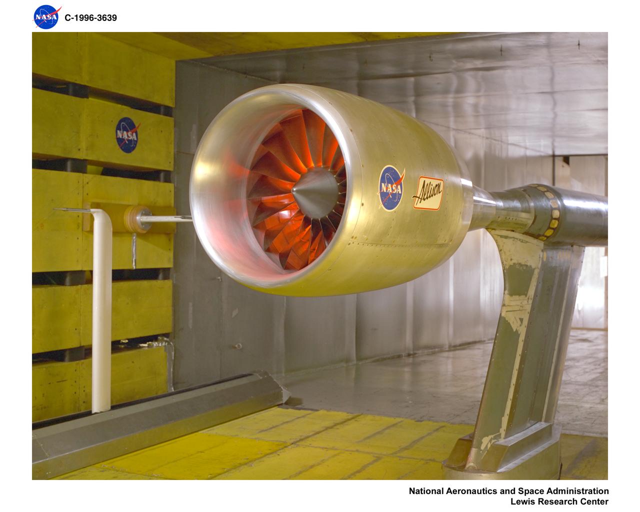
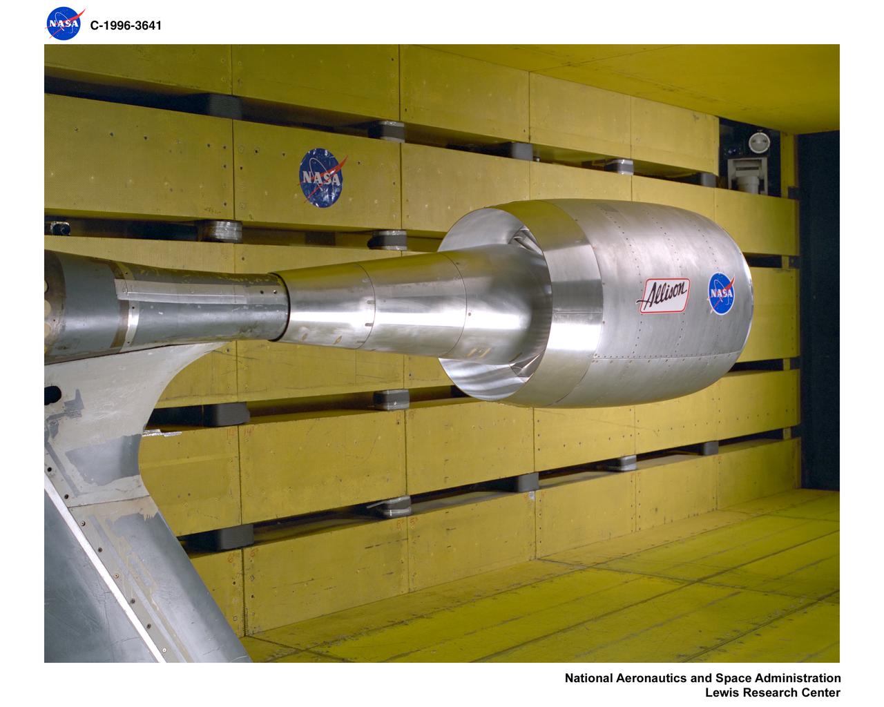
ALLISON DUCTED FAN IN 9X15 FOOT LOW SPEED WIND TUNNEL
ALLISON DUCTED FAN IN 9X15 FOOT LOW SPEED WIND TUNNEL
ALLISON DUCTED FAN IN 9X15 FOOT LOW SPEED WIND TUNNEL
3/4 front view offull scale X-22A ducted fan model. Chuck Greco
3/4 front view of full scale X-22A ducted fan model. Chuck Greco
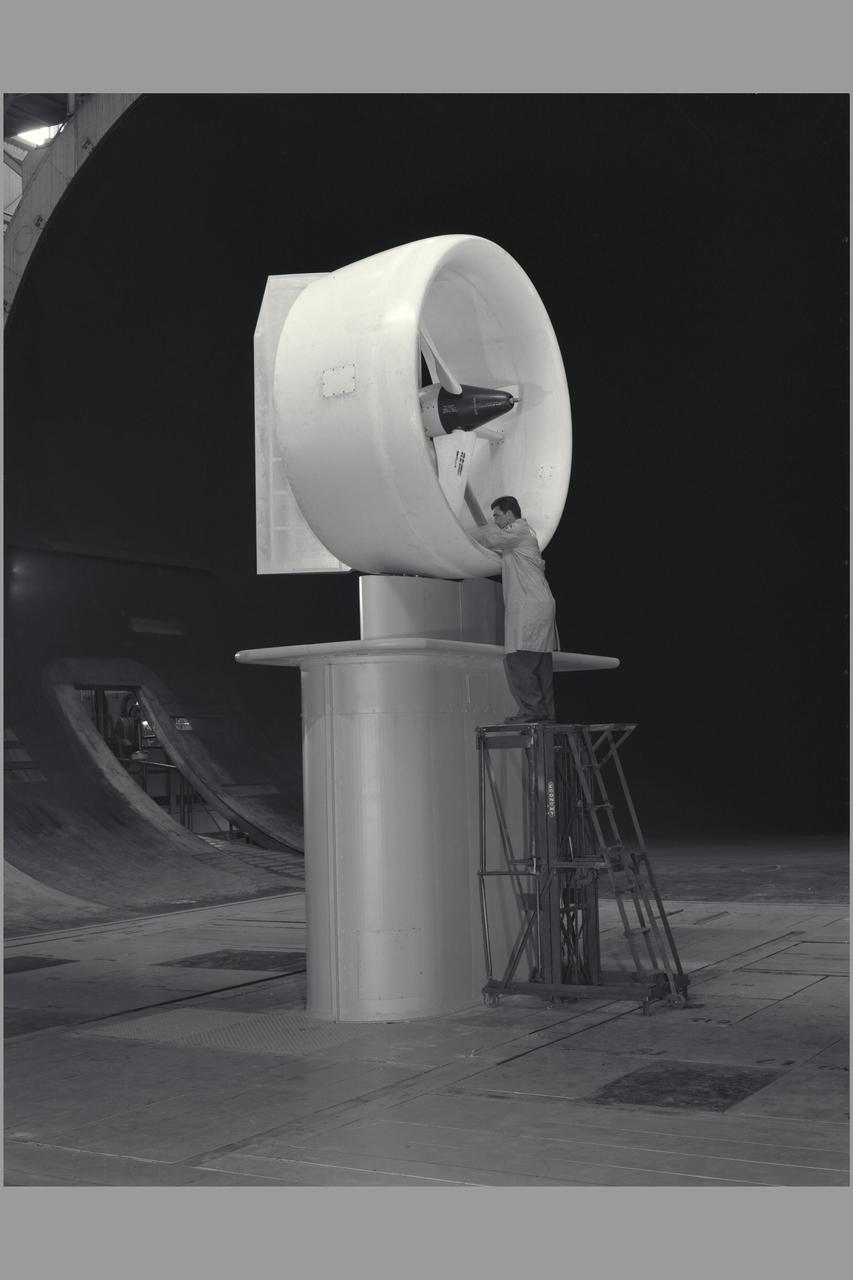
3/4 front view of full scale X-22A ducted fan model. Chuck Greco
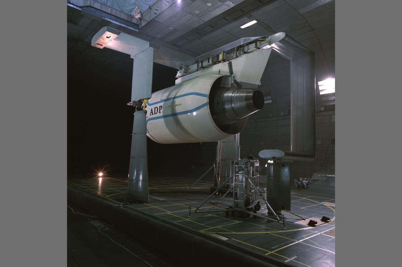
Pratt & Whitney Advanced Ducted Propulsor (ADP) Engine Test-590 in the NASA Ames 40x80ft Subsonic Wind Tunnel. The Pratt & Whitney Advanced Ducted Prop (ADP) demonstrator undergoing acoustic and fan performance testing. ADP technology could lead to decreased fuel consumption and noise.
Pratt & Whitney Advanced Ducted Propulsor (ADP) Engine Test-590 in NASA Ames 40x80ft Subsonic Wind Tunnel. The Pratt & Whitney advanced ducted prop (ADP) demonstrator undergoing acoustic and fan performance testing. ADP technology could lead to decreased fuel consumption and noise.
3/4 front, top view of Noriar Lift Engine Pod installation in Ames 40x80 foot wind tunnel
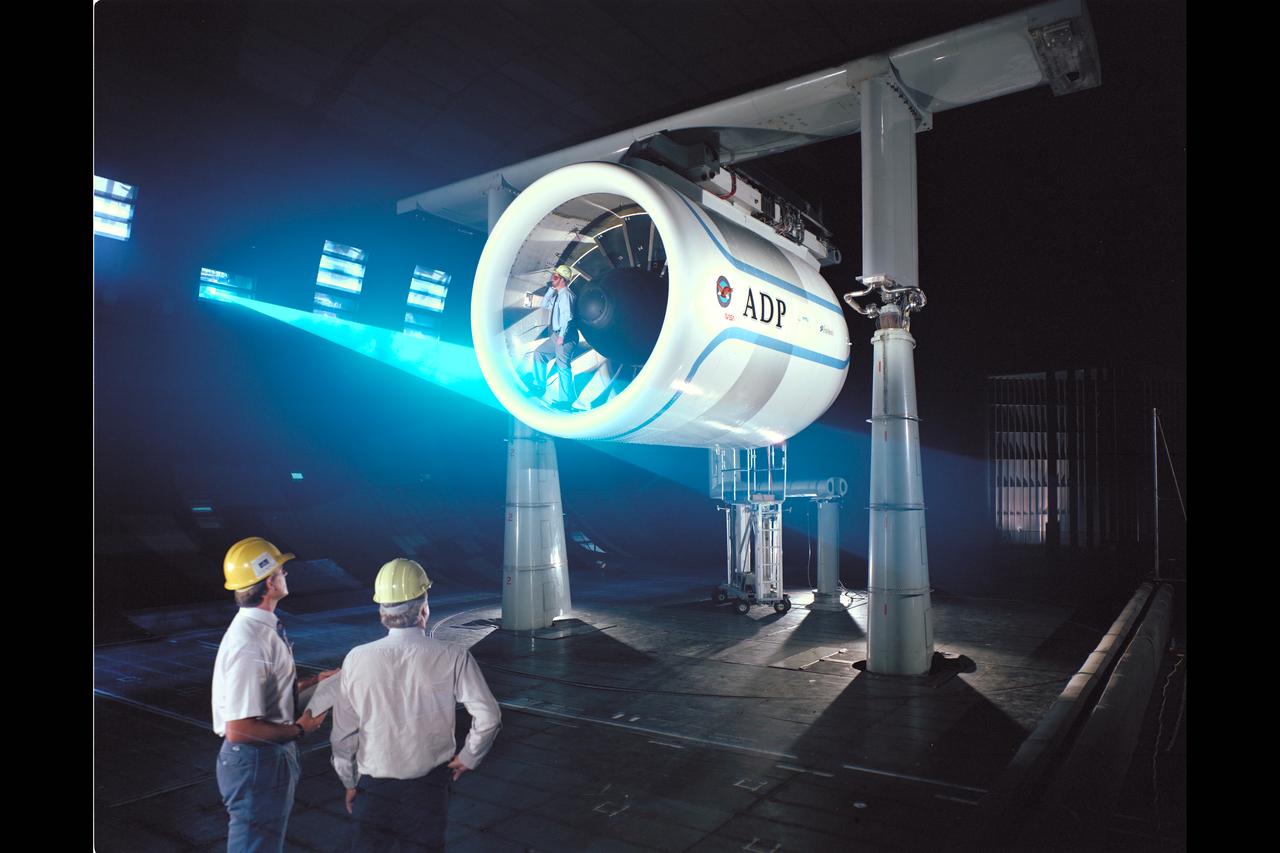
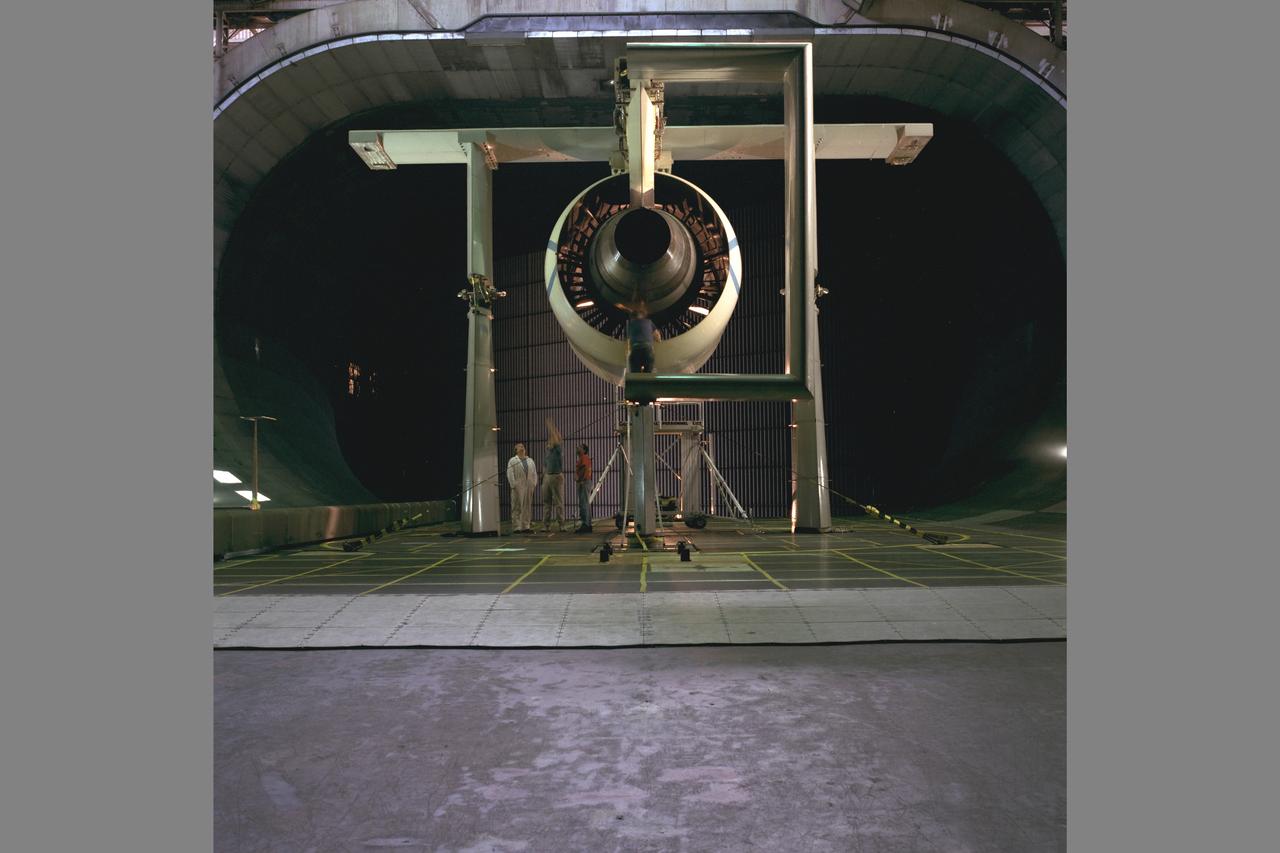
Pratt & Whitney Advanced Ducted Propulsor (ADP) Engine Test-590 in NASA Ames 40x80ft Subsonic Wind Tunnel. The Pratt & Whitney advanced ducted prop (ADP) demonstrator undergoing acoustic and fan performance testing. ADP technology could lead to decreased fuel consumption and noise. Shown here are NASA Ames engineers Peter Zell (left) and Dr Clifton Horne (right) preparing for a laser light sheet for a flow visualization test. Shown standing in the nacelle of the ADP is John Girvin, senior test engineer for Pratt & Whitney.
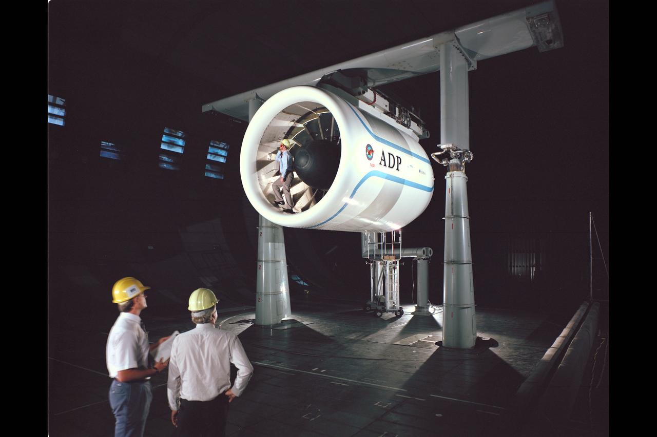
Pratt & Whitney Advanced Ducted Propulsor (ADP) Engine Test-590 in NASA Ames 40x80ft Subsonic Wind Tunnel. The Pratt & Whitney advanced ducted prop (ADP) demonstrator undergoing acoustic and fan performance testing. ADP technology could lead to decreased fuel consumption and noise. Shown here are NASA Ames engineers Peter Zell (left) and Dr Clifton Horne (right) preparing for a laser light sheet for a flow visualization test. Shown standing in the nacelle of the ADP is John Girvin, senior test engineer for Pratt & Whitney.
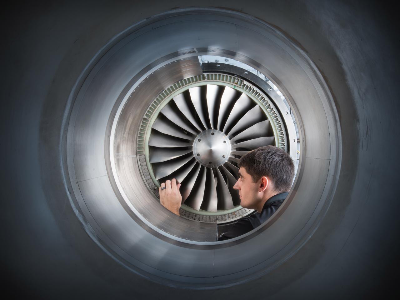
Acoustic Casing Treatment Testing Completed in the W-8 Single Stage Axial Compressor Facility at NASA Glenn. Four different over-the-rotor acoustic casing treatment concepts were tested along with two baseline configurations. Testing included steady-aerodynamic measurements of fan performance, hotfilm turbulence measurements, and inlet acoustic measurements with an in-duct array.
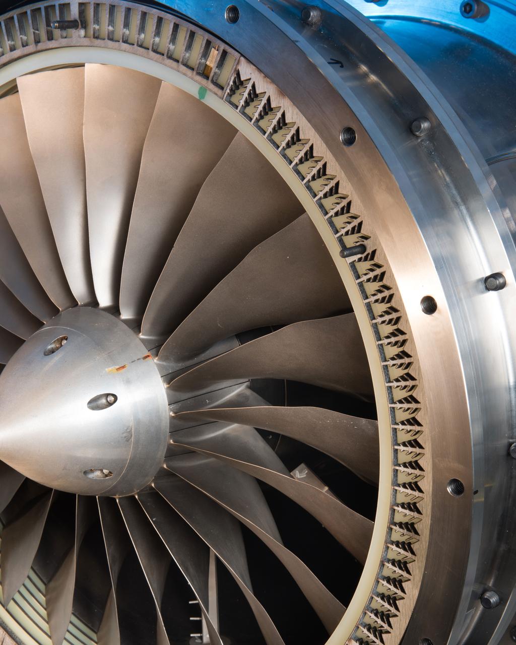
Acoustic Casing Treatment Testing Completed in the W-8 Single Stage Axial Compressor Facility at NASA Glenn. Four different over-the-rotor acoustic casing treatment concepts were tested along with two baseline configurations. Testing included steady-aerodynamic measurements of fan performance, hotfilm turbulence measurements, and inlet acoustic measurements with an in-duct array.
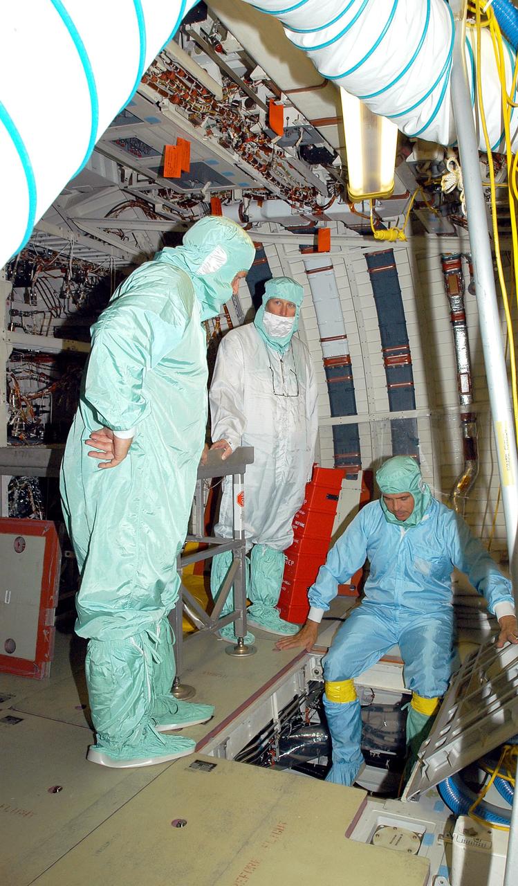
KENNEDY SPACE CENTER, FLA. - In the middeck of Endeavour, in the Orbiter Processing Facility, Center Director Jim Kennedy (far left) watches as a technician gets ready to lower himself through the LiOH door into the Environmental Control and Life Support System (ECLSS) bay. LiOH refers to lithium hydroxide, canisters of which are stored in the ECLSS bay under the middeck floor. During flight, cabin air from the cabin fan is ducted to two LiOH canisters, where carbon dioxide is removed and activated charcoal removes odors and trace contaminants. Kennedy is taking an opportunity to learn first-hand what workers are doing to enable Return to Flight. Endeavour is in an Orbiter Major Modification period.

Title: W-8 Fan Acoustic Casing Treatment Test on the Source Diagnostic Test Rotor Alone Hardware Program: Advanced Air Vehicles Program (AAVP) Project: Advanced Air Transport Technology (AATT) Sub-project: Aircraft Noise Reduction (ANR) Weekly Highlight: · Acoustic Casing Treatment Testing Completed in the W-8 Single Stage Axial Compressor Facility: Testing of Acoustic Casing Treatments on the Source Diagnostic Test (SDT) rotor alone hardware which had begun in early January was completed on Thursday, February 16th. Four different over-the-rotor acoustic casing treatment concepts were tested along with two baseline configurations. Testing included steady-aerodynamic measurements of fan performance, hotfilm turbulence measurements, and inlet acoustic measurements with an in-duct array. These measurements will be used to assess the aerodynamic and acoustic impact of fan acoustic casing treatments on a high bypass ratio fan at TRL 3. This test was the last of 3 planned tests of potential over-the-rotor acoustic casing treatments. The first treatment test was completed in the Normal Incidence Tube (NIT) at Langley Research Center (LaRC) in Fall 2015 and the second was completed on the Advanced Noise Control Fan (ANCF) in the Aero-Acoustic Propulsion Laboratory (AAPL) in Winter 2016. This work is supported by the Aircraft Noise Reduction (ANR) subproject of the Advanced Air Transport Technology (AATT) Project. (POC: LTV/ Rick Bozak 3-5160)
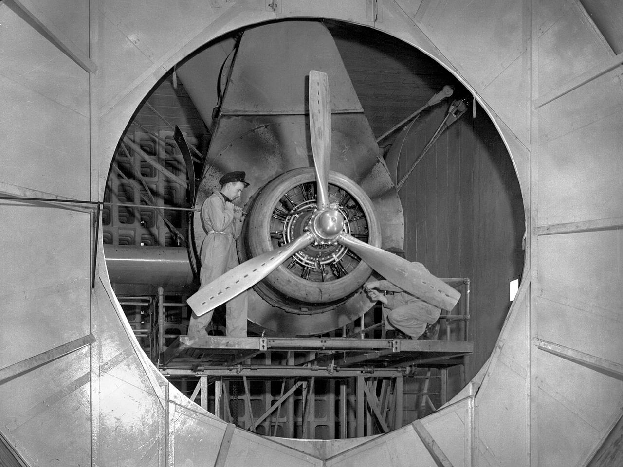
A Wright Aeronautical R–2600 Cyclone piston engine installed in the Engine Propeller Research Building, or Prop House, at the National Advisory Committee for Aeronautics (NACA) Aircraft Engine Research Laboratory. The R–2600 was among the most powerful engines that emerged during World War II. The engine, which was developed for commercial applications in 1939, was used to power the North American B–25 bomber and several other midsize military aircraft. The higher altitudes required by the military caused problems with the engine's cooling and fuel systems. The military requested that the Aircraft Engine Research Laboratory analyze the performance of the R–2600, improve its cooling system, and reduce engine knock. The NACA researchers subjected the engine to numerous tests in its Prop House. The R–2600 was the subject of the laboratory's first technical report, which was written by members of the Fuels and Lubricants Division. The Prop House contained soundproof test cells in which piston engines and propellers were mounted and operated at high powers. Electrically driven fans drew air through ducts to create a stream of cooling air over the engines. Researchers tested the performance of fuels, turbochargers, water-injection and cooling systems here during World War II. The facility was also investigated a captured German V–I buzz bomb during the war.
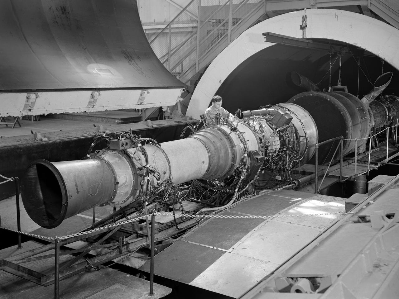
A Rolls Royce Avon RA-14 engine was tested in the Altitude Wind Tunnel at the National Advisory Committee for Aeronautics’ (NACA) Lewis Flight Propulsion Laboratory. The Avon RA-14 engine was a 16-stage axial-flow compressor turbojet capable of producing 9,500 pounds of thrust. The Avon replaced Rolls Royce’s successful Nene engine in 1950 and remained in service until 1974. It was one of several British engines studied in the tunnel during the 1950s. The Altitude Wind Tunnel went through a series of modifications in 1951 to increase its capabilities. An annex was attached to the Exhauster Building to house three new Ingersoll-Rand compressors. The wooden blades on the tunnel’s 31-foot diameter fan were replaced, a pump house and exhaust cooler were constructed underneath the tunnel, and two new cells were added to the cooling tower. The modified wind tunnel continued to analyze jet engines in the 1950s, although the engines, like the RA-14 seen here, were much more powerful than those studied several years before. Lewis researchers studied the RA-14 turbojet engine in the Altitude Wind Tunnel for 11 months in 1956. The engine was mounted on a stand capable of gauging engine thrust, and the tunnel’s air was ducted to the engine through a venturi and bellmouth inlet, seen in this photograph. The initial studies established the engine’s performance characteristics with a fixed-area nozzle and its acceleration characteristics. The researchers also used the tunnel to investigate windmilling of the compressor blades, restarting at high altitudes, and the engine’s performance limits at altitude.