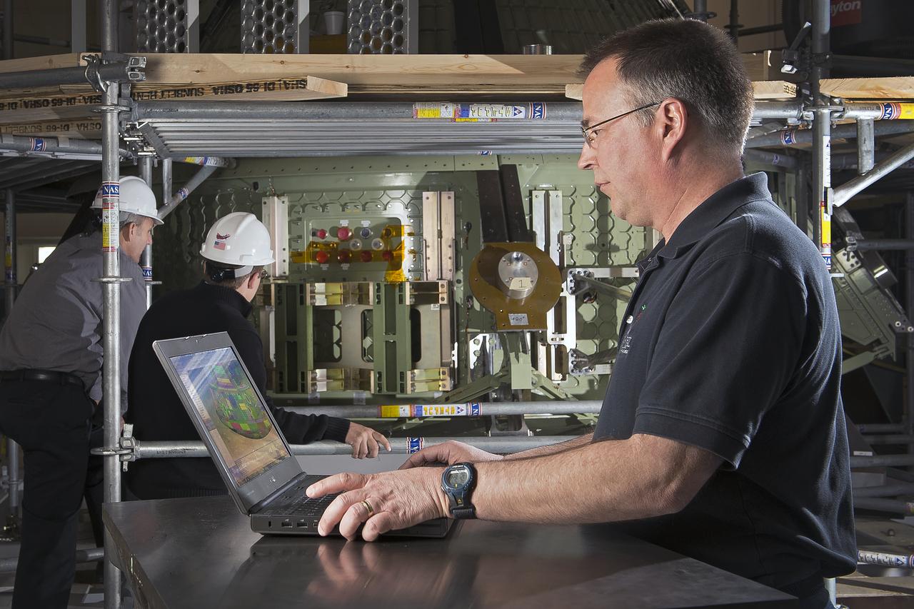
(NESC) NASA Engineering and Safety Center Orion Heat Shield Carrier Structure: Titanium Orthogrid heat shield sub-component dynamic test article : person in the photo Jim Jeans (Background: Mike Kirsch, James Ainsworth)
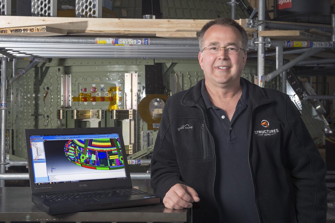
(NESC) NASA Engineering and Safety Center Orion Heat Shield Carrier Structure: Titanium Orthogrid heat shield sub-component dynamic test article : person in the photo Jim Jeans
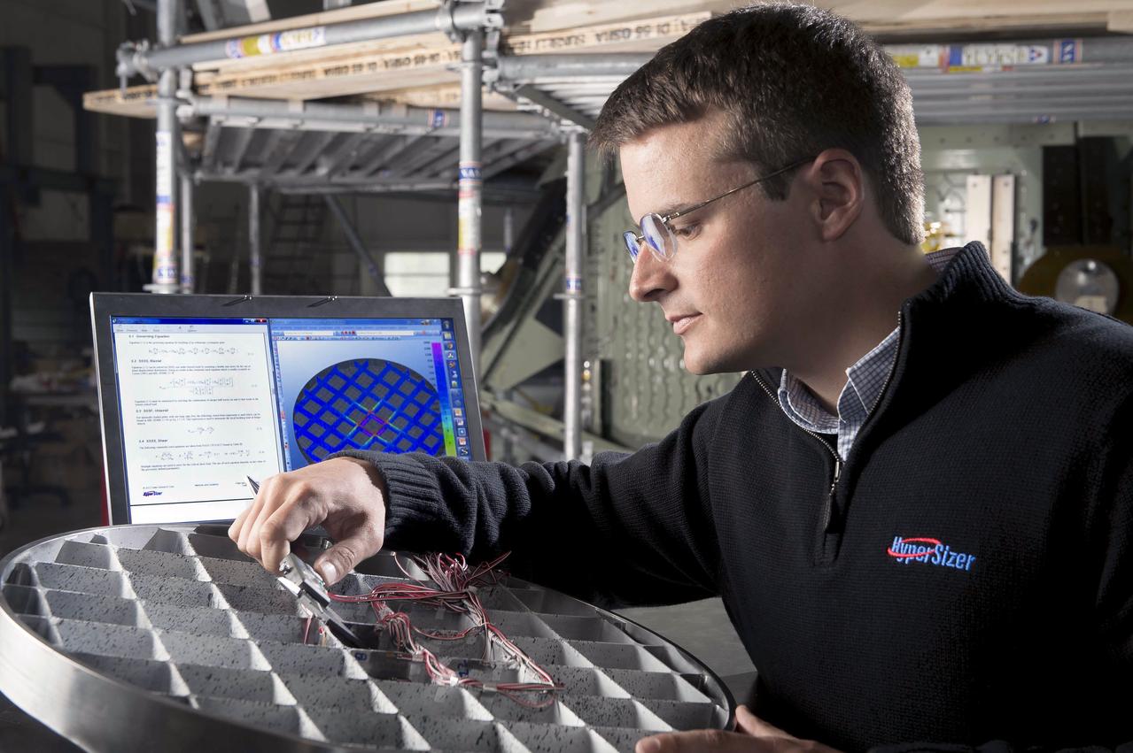
(NESC) NASA Engineering and Safety Center Orion Heat Shield Carrier Structure: Titanium Orthogrid heat shield sub-component dynamic test article :person in the photo James Ainsworth
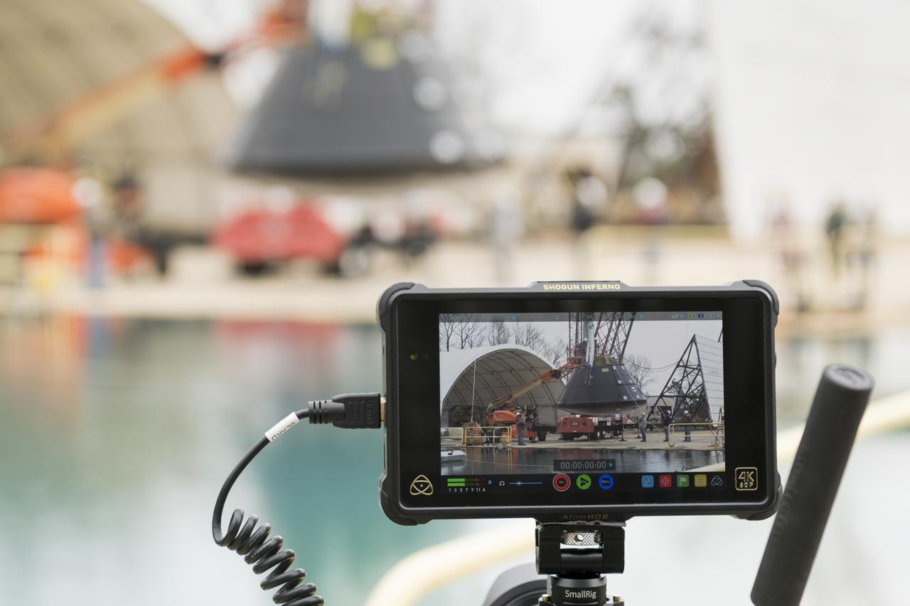
Images of Structural Test Article (STA) vertical water impact testing (WIT) testing at Impact Dynamics Facility NASA Langley Research Center.
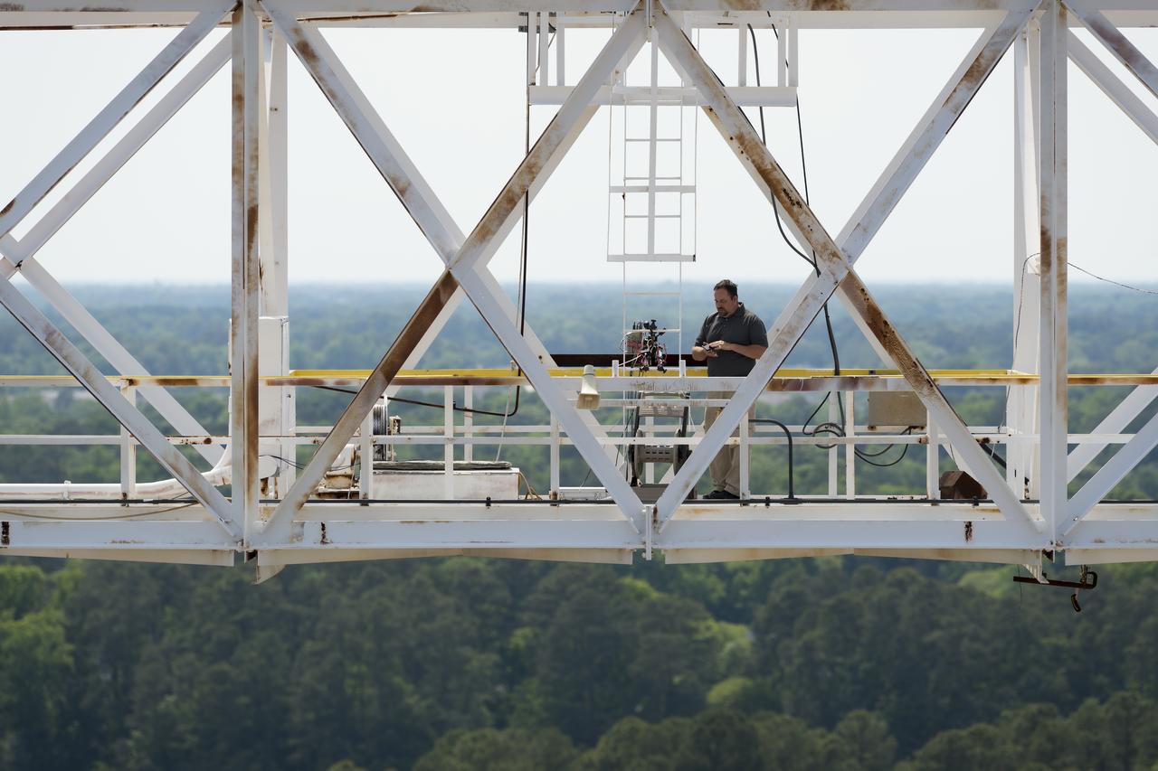
Images from Orion Structural Test Article (STA) vertical water impact testing (WIT) Swing Test 4, Photographer Harlen Capen at the top of the Impact Dynamics Facility or Gantry as it is know at NASA Langley Research Center.
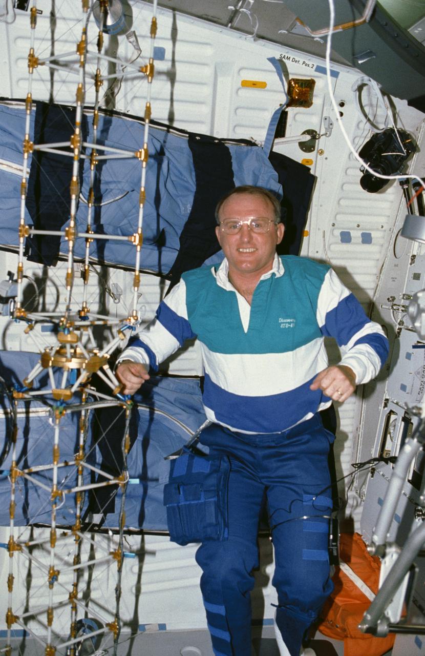
STS048-10-023 (16 Sept 1991) --- Astronaut James F. Buchli poses with the structural test article (STA), a model of the space station truss structure. The STA is part of the middeck zero gravity dynamics experiment (MODE). MODE was designed to study the vibration characteristics of the jointed truss structure. The structural test article includes four strain gauges and eleven accelerometers and is vibrated by an actuator. Assembled by crewmembers in the Shuttle orbiter's middeck, the device is about 72 inches long with an 8-inch square cross section.
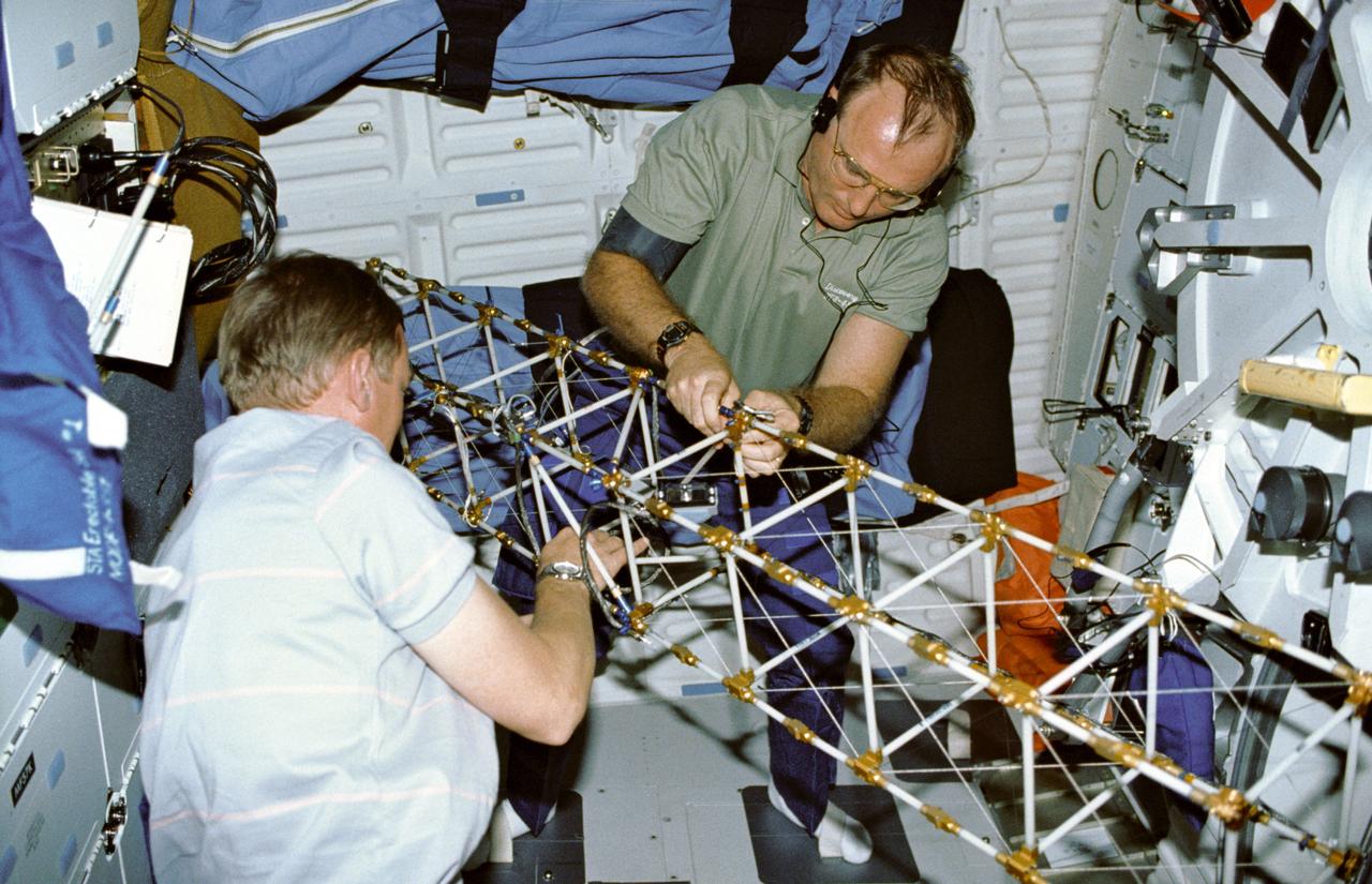
STS048-09-019 (16 Sept 1991) --- Astronauts Mark N. Brown, left, and James F. Buchli work with the structural test article (STA), a model of the space station truss structure. STA is part of the middeck zero gravity dynamics experiment (MODE). MODE was designed to study the vibration characteristics of the jointed truss structure. The structural test article includes four strain gauges and eleven accelerometers and is vibrated by an actuator. Assembled by crewmembers in the Shuttle orbiter's middeck, the device is about 72 inches long with an 8-inch square cross section.

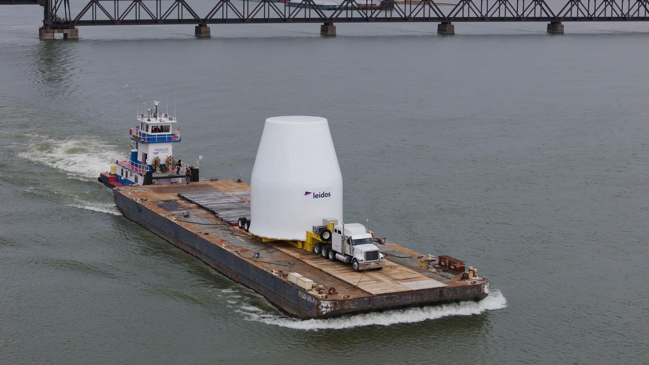
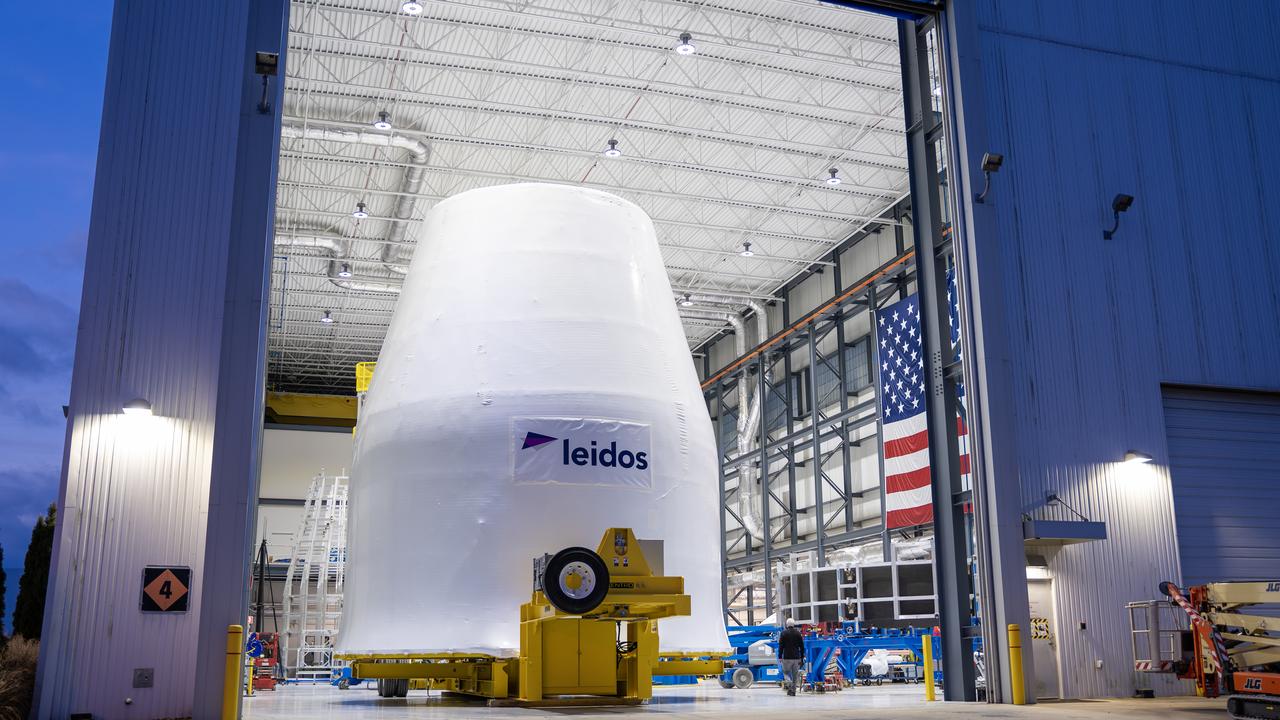
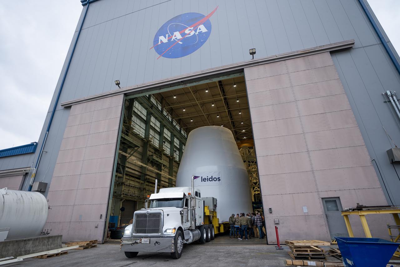
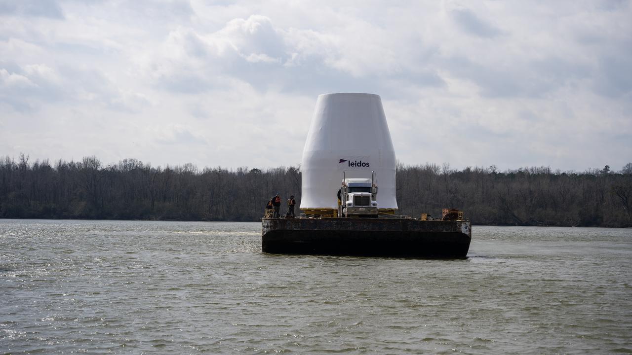
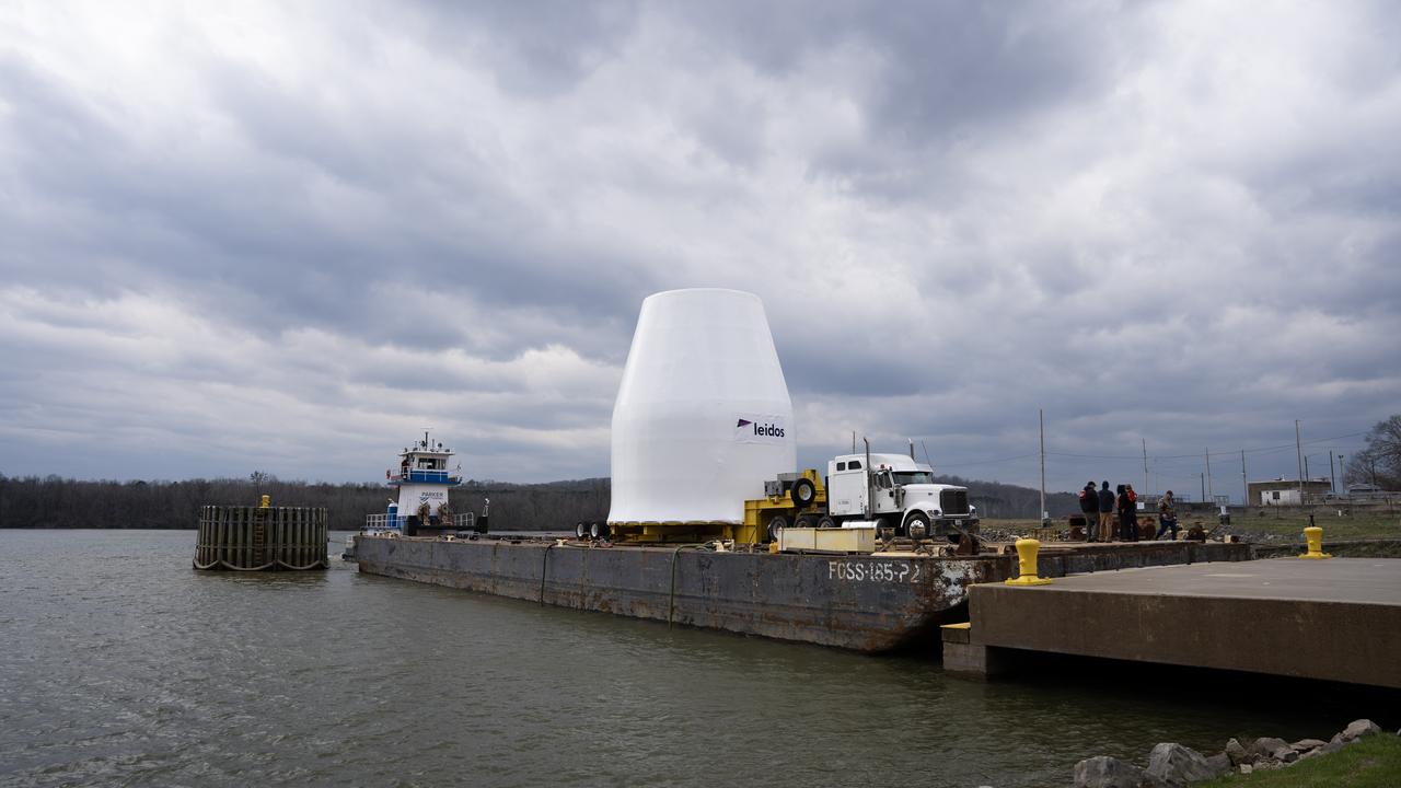
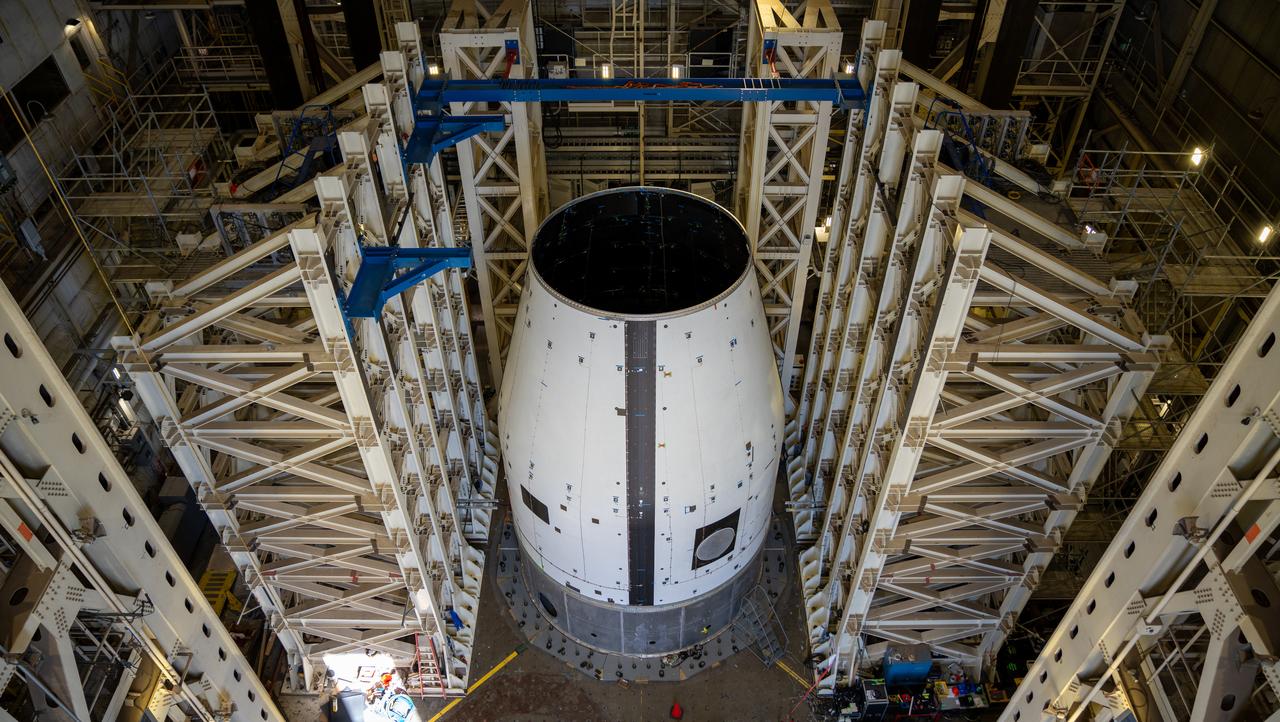
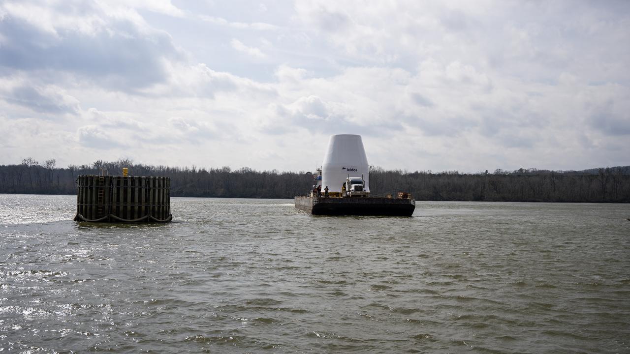
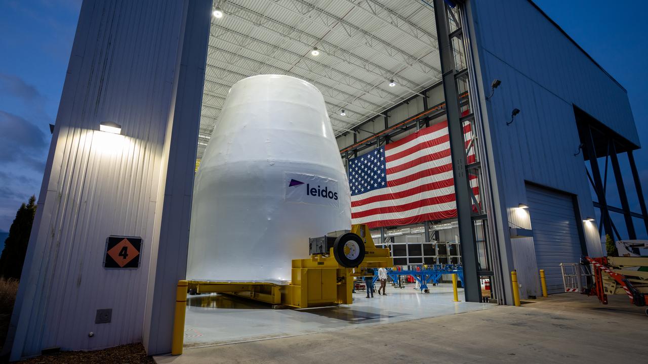
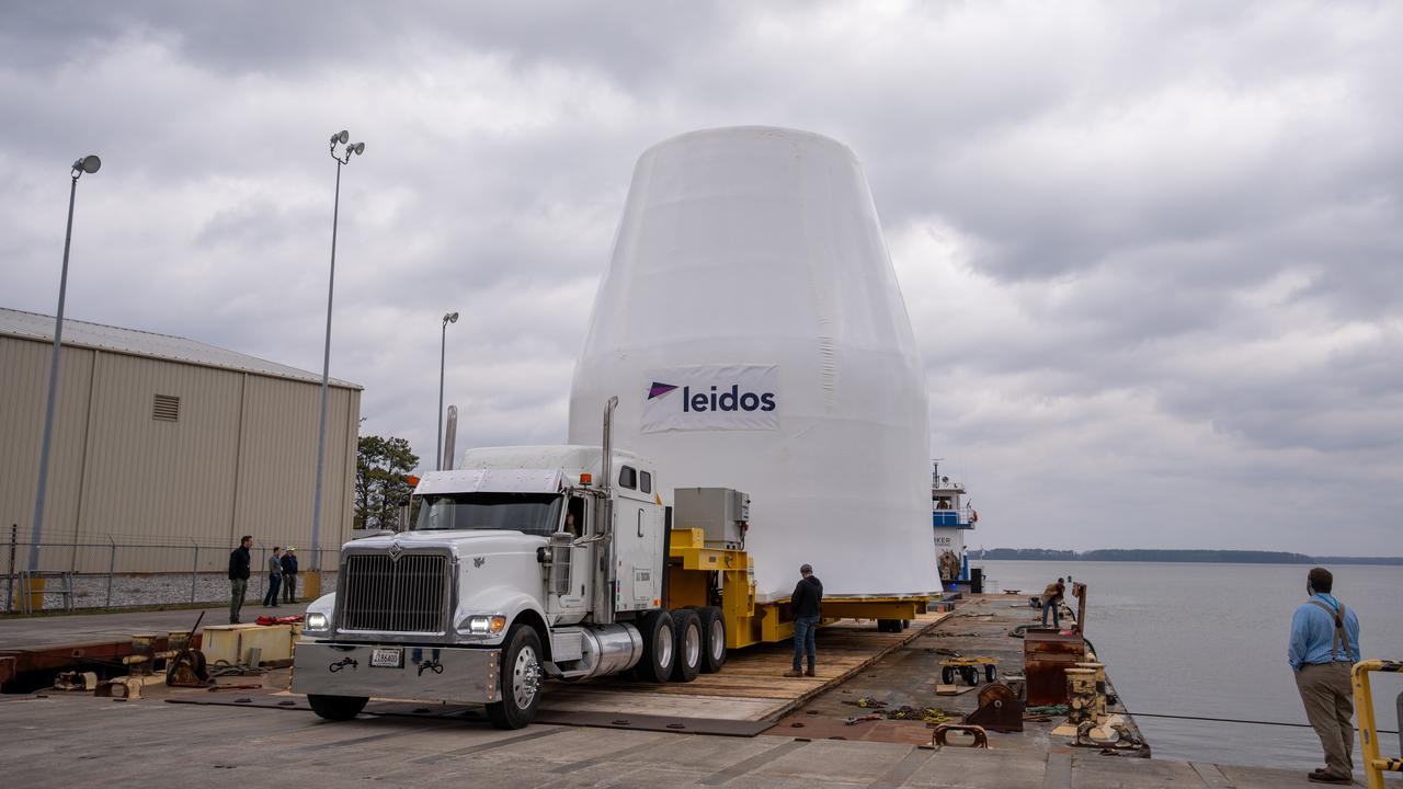
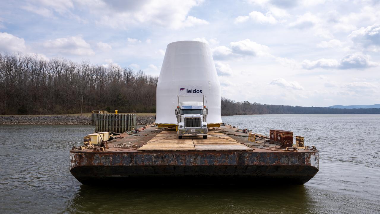
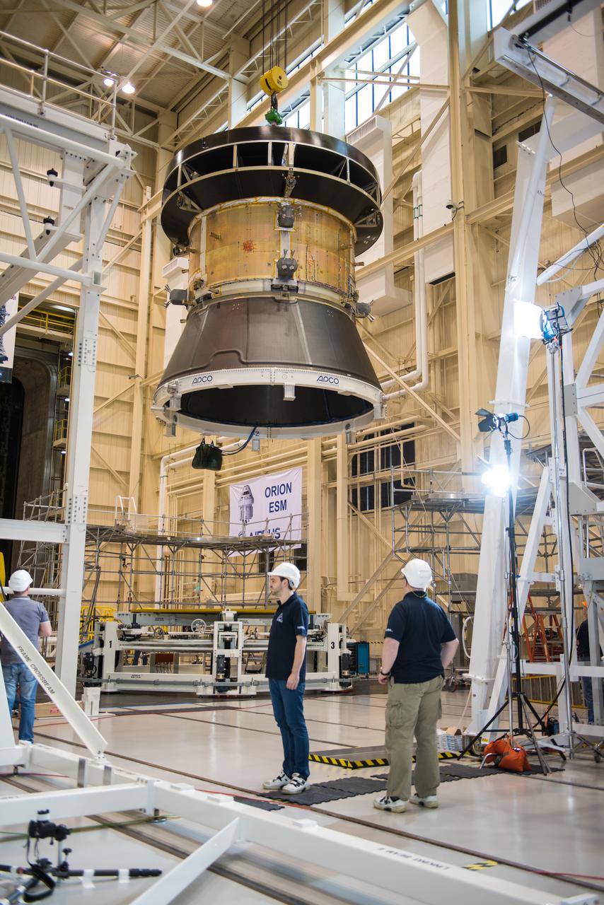
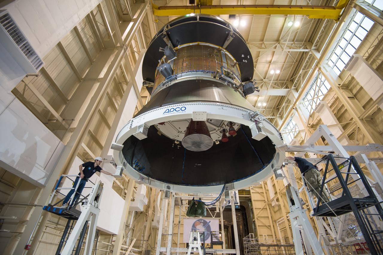
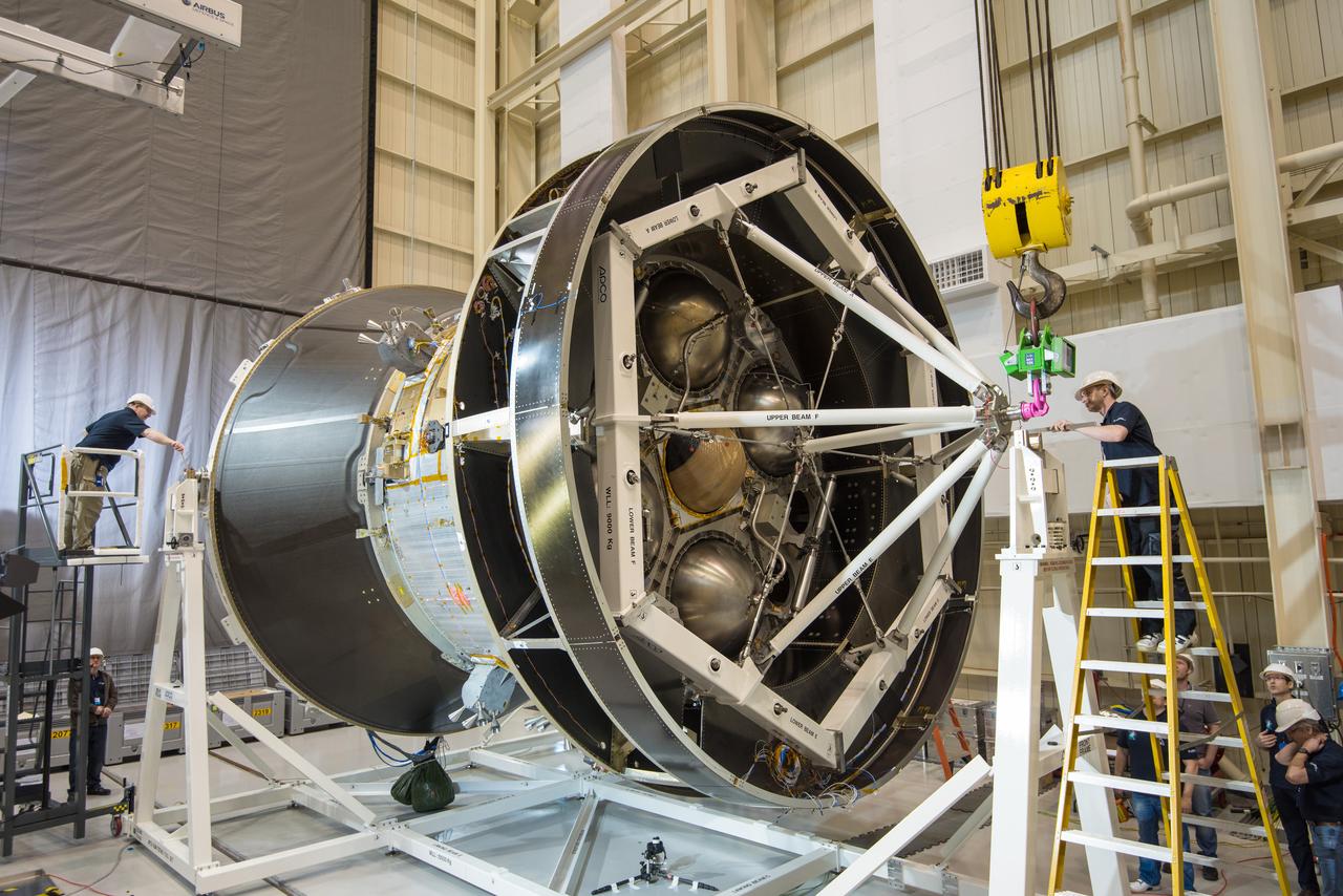
These photos and videos show how crews guided a test version of the universal stage adapter for NASA’s more powerful version of its SLS (Space Launch System) rocket to Building 4619 at the agency’s Marshall Space Flight Center in Huntsville, Alabama, Feb. 22. Built by Leidos, the lead contractor for the universal stage adapter, crews transported the hardware from a Leidos facility in Decatur, Alabama, the same day. The universal stage adapter will connect the SLS rocket’s upgraded in-space propulsion stage, called the exploration upper stage, to NASA’s Orion spacecraft as part of the evolved Block 1B configuration of the SLS rocket. It will also serve as a compartment capable of accommodating large payloads, such as modules or other exploration spacecraft. In Building 4619’s Load Test Annex High Bay at Marshall, the development test article will first undergo modal testing that will shake the hardware to validate dynamic models. Later, during ultimate load testing, force will be applied vertically and to the sides of the hardware. Unlike the flight hardware, the development test article has flaws intentionally included in its design, which will help engineers verity that the flight adapter can withstand the extreme forces it will face during launch and flight.
These photos and videos show how crews guided a test version of the universal stage adapter for NASA’s more powerful version of its SLS (Space Launch System) rocket to Building 4619 at the agency’s Marshall Space Flight Center in Huntsville, Alabama, Feb. 22. Built by Leidos, the lead contractor for the universal stage adapter, crews transported the hardware from a Leidos facility in Decatur, Alabama, the same day. The universal stage adapter will connect the SLS rocket’s upgraded in-space propulsion stage, called the exploration upper stage, to NASA’s Orion spacecraft as part of the evolved Block 1B configuration of the SLS rocket. It will also serve as a compartment capable of accommodating large payloads, such as modules or other exploration spacecraft. In Building 4619’s Load Test Annex High Bay at Marshall, the development test article will first undergo modal testing that will shake the hardware to validate dynamic models. Later, during ultimate load testing, force will be applied vertically and to the sides of the hardware. Unlike the flight hardware, the development test article has flaws intentionally included in its design, which will help engineers verity that the flight adapter can withstand the extreme forces it will face during launch and flight.
These photos and videos show how crews guided a test version of the universal stage adapter for NASA’s more powerful version of its SLS (Space Launch System) rocket to Building 4619 at the agency’s Marshall Space Flight Center in Huntsville, Alabama, Feb. 22. Built by Leidos, the lead contractor for the universal stage adapter, crews transported the hardware from a Leidos facility in Decatur, Alabama, the same day. The universal stage adapter will connect the SLS rocket’s upgraded in-space propulsion stage, called the exploration upper stage, to NASA’s Orion spacecraft as part of the evolved Block 1B configuration of the SLS rocket. It will also serve as a compartment capable of accommodating large payloads, such as modules or other exploration spacecraft. In Building 4619’s Load Test Annex High Bay at Marshall, the development test article will first undergo modal testing that will shake the hardware to validate dynamic models. Later, during ultimate load testing, force will be applied vertically and to the sides of the hardware. Unlike the flight hardware, the development test article has flaws intentionally included in its design, which will help engineers verity that the flight adapter can withstand the extreme forces it will face during launch and flight.
These photos and videos show how crews guided a test version of the universal stage adapter for NASA’s more powerful version of its SLS (Space Launch System) rocket to Building 4619 at the agency’s Marshall Space Flight Center in Huntsville, Alabama, Feb. 22. Built by Leidos, the lead contractor for the universal stage adapter, crews transported the hardware from a Leidos facility in Decatur, Alabama, the same day. The universal stage adapter will connect the SLS rocket’s upgraded in-space propulsion stage, called the exploration upper stage, to NASA’s Orion spacecraft as part of the evolved Block 1B configuration of the SLS rocket. It will also serve as a compartment capable of accommodating large payloads, such as modules or other exploration spacecraft. In Building 4619’s Load Test Annex High Bay at Marshall, the development test article will first undergo modal testing that will shake the hardware to validate dynamic models. Later, during ultimate load testing, force will be applied vertically and to the sides of the hardware. Unlike the flight hardware, the development test article has flaws intentionally included in its design, which will help engineers verity that the flight adapter can withstand the extreme forces it will face during launch and flight.

These photos and videos show how crews guided a test version of the universal stage adapter for NASA’s more powerful version of its SLS (Space Launch System) rocket to Building 4619 at the agency’s Marshall Space Flight Center in Huntsville, Alabama, Feb. 22. Built by Leidos, the lead contractor for the universal stage adapter, crews transported the hardware from a Leidos facility in Decatur, Alabama, the same day. The universal stage adapter will connect the SLS rocket’s upgraded in-space propulsion stage, called the exploration upper stage, to NASA’s Orion spacecraft as part of the evolved Block 1B configuration of the SLS rocket. It will also serve as a compartment capable of accommodating large payloads, such as modules or other exploration spacecraft. In Building 4619’s Load Test Annex High Bay at Marshall, the development test article will first undergo modal testing that will shake the hardware to validate dynamic models. Later, during ultimate load testing, force will be applied vertically and to the sides of the hardware. Unlike the flight hardware, the development test article has flaws intentionally included in its design, which will help engineers verity that the flight adapter can withstand the extreme forces it will face during launch and flight.
These photos and videos show how crews guided a test version of the universal stage adapter for NASA’s more powerful version of its SLS (Space Launch System) rocket to Building 4619 at the agency’s Marshall Space Flight Center in Huntsville, Alabama, Feb. 22. Built by Leidos, the lead contractor for the universal stage adapter, crews transported the hardware from a Leidos facility in Decatur, Alabama, the same day. The universal stage adapter will connect the SLS rocket’s upgraded in-space propulsion stage, called the exploration upper stage, to NASA’s Orion spacecraft as part of the evolved Block 1B configuration of the SLS rocket. It will also serve as a compartment capable of accommodating large payloads, such as modules or other exploration spacecraft. In Building 4619’s Load Test Annex High Bay at Marshall, the development test article will first undergo modal testing that will shake the hardware to validate dynamic models. Later, during ultimate load testing, force will be applied vertically and to the sides of the hardware. Unlike the flight hardware, the development test article has flaws intentionally included in its design, which will help engineers verity that the flight adapter can withstand the extreme forces it will face during launch and flight.
These photos and videos show how crews guided a test version of the universal stage adapter for NASA’s more powerful version of its SLS (Space Launch System) rocket to Building 4619 at the agency’s Marshall Space Flight Center in Huntsville, Alabama, Feb. 22. Built by Leidos, the lead contractor for the universal stage adapter, crews transported the hardware from a Leidos facility in Decatur, Alabama, the same day. The universal stage adapter will connect the SLS rocket’s upgraded in-space propulsion stage, called the exploration upper stage, to NASA’s Orion spacecraft as part of the evolved Block 1B configuration of the SLS rocket. It will also serve as a compartment capable of accommodating large payloads, such as modules or other exploration spacecraft. In Building 4619’s Load Test Annex High Bay at Marshall, the development test article will first undergo modal testing that will shake the hardware to validate dynamic models. Later, during ultimate load testing, force will be applied vertically and to the sides of the hardware. Unlike the flight hardware, the development test article has flaws intentionally included in its design, which will help engineers verity that the flight adapter can withstand the extreme forces it will face during launch and flight.
These photos and videos show how crews guided a test version of the universal stage adapter for NASA’s more powerful version of its SLS (Space Launch System) rocket to Building 4619 at the agency’s Marshall Space Flight Center in Huntsville, Alabama, Feb. 22. Built by Leidos, the lead contractor for the universal stage adapter, crews transported the hardware from a Leidos facility in Decatur, Alabama, the same day. The universal stage adapter will connect the SLS rocket’s upgraded in-space propulsion stage, called the exploration upper stage, to NASA’s Orion spacecraft as part of the evolved Block 1B configuration of the SLS rocket. It will also serve as a compartment capable of accommodating large payloads, such as modules or other exploration spacecraft. In Building 4619’s Load Test Annex High Bay at Marshall, the development test article will first undergo modal testing that will shake the hardware to validate dynamic models. Later, during ultimate load testing, force will be applied vertically and to the sides of the hardware. Unlike the flight hardware, the development test article has flaws intentionally included in its design, which will help engineers verity that the flight adapter can withstand the extreme forces it will face during launch and flight.
These photos and videos show how crews guided a test version of the universal stage adapter for NASA’s more powerful version of its SLS (Space Launch System) rocket to Building 4619 at the agency’s Marshall Space Flight Center in Huntsville, Alabama, Feb. 22. Built by Leidos, the lead contractor for the universal stage adapter, crews transported the hardware from a Leidos facility in Decatur, Alabama, the same day. The universal stage adapter will connect the SLS rocket’s upgraded in-space propulsion stage, called the exploration upper stage, to NASA’s Orion spacecraft as part of the evolved Block 1B configuration of the SLS rocket. It will also serve as a compartment capable of accommodating large payloads, such as modules or other exploration spacecraft. In Building 4619’s Load Test Annex High Bay at Marshall, the development test article will first undergo modal testing that will shake the hardware to validate dynamic models. Later, during ultimate load testing, force will be applied vertically and to the sides of the hardware. Unlike the flight hardware, the development test article has flaws intentionally included in its design, which will help engineers verity that the flight adapter can withstand the extreme forces it will face during launch and flight.
These photos and videos show how crews guided a test version of the universal stage adapter for NASA’s more powerful version of its SLS (Space Launch System) rocket to Building 4619 at the agency’s Marshall Space Flight Center in Huntsville, Alabama, Feb. 22. Built by Leidos, the lead contractor for the universal stage adapter, crews transported the hardware from a Leidos facility in Decatur, Alabama, the same day. The universal stage adapter will connect the SLS rocket’s upgraded in-space propulsion stage, called the exploration upper stage, to NASA’s Orion spacecraft as part of the evolved Block 1B configuration of the SLS rocket. It will also serve as a compartment capable of accommodating large payloads, such as modules or other exploration spacecraft. In Building 4619’s Load Test Annex High Bay at Marshall, the development test article will first undergo modal testing that will shake the hardware to validate dynamic models. Later, during ultimate load testing, force will be applied vertically and to the sides of the hardware. Unlike the flight hardware, the development test article has flaws intentionally included in its design, which will help engineers verity that the flight adapter can withstand the extreme forces it will face during launch and flight.
These photos and videos show how crews guided a test version of the universal stage adapter for NASA’s more powerful version of its SLS (Space Launch System) rocket to Building 4619 at the agency’s Marshall Space Flight Center in Huntsville, Alabama, Feb. 22. Built by Leidos, the lead contractor for the universal stage adapter, crews transported the hardware from a Leidos facility in Decatur, Alabama, the same day. The universal stage adapter will connect the SLS rocket’s upgraded in-space propulsion stage, called the exploration upper stage, to NASA’s Orion spacecraft as part of the evolved Block 1B configuration of the SLS rocket. It will also serve as a compartment capable of accommodating large payloads, such as modules or other exploration spacecraft. In Building 4619’s Load Test Annex High Bay at Marshall, the development test article will first undergo modal testing that will shake the hardware to validate dynamic models. Later, during ultimate load testing, force will be applied vertically and to the sides of the hardware. Unlike the flight hardware, the development test article has flaws intentionally included in its design, which will help engineers verity that the flight adapter can withstand the extreme forces it will face during launch and flight.

These photos and videos show how crews guided a test version of the universal stage adapter for NASA’s more powerful version of its SLS (Space Launch System) rocket to Building 4619 at the agency’s Marshall Space Flight Center in Huntsville, Alabama, Feb. 22. Built by Leidos, the lead contractor for the universal stage adapter, crews transported the hardware from a Leidos facility in Decatur, Alabama, the same day. The universal stage adapter will connect the SLS rocket’s upgraded in-space propulsion stage, called the exploration upper stage, to NASA’s Orion spacecraft as part of the evolved Block 1B configuration of the SLS rocket. It will also serve as a compartment capable of accommodating large payloads, such as modules or other exploration spacecraft. In Building 4619’s Load Test Annex High Bay at Marshall, the development test article will first undergo modal testing that will shake the hardware to validate dynamic models. Later, during ultimate load testing, force will be applied vertically and to the sides of the hardware. Unlike the flight hardware, the development test article has flaws intentionally included in its design, which will help engineers verity that the flight adapter can withstand the extreme forces it will face during launch and flight.
These photos and videos show how crews guided a test version of the universal stage adapter for NASA’s more powerful version of its SLS (Space Launch System) rocket to Building 4619 at the agency’s Marshall Space Flight Center in Huntsville, Alabama, Feb. 22. Built by Leidos, the lead contractor for the universal stage adapter, crews transported the hardware from a Leidos facility in Decatur, Alabama, the same day. The universal stage adapter will connect the SLS rocket’s upgraded in-space propulsion stage, called the exploration upper stage, to NASA’s Orion spacecraft as part of the evolved Block 1B configuration of the SLS rocket. It will also serve as a compartment capable of accommodating large payloads, such as modules or other exploration spacecraft. In Building 4619’s Load Test Annex High Bay at Marshall, the development test article will first undergo modal testing that will shake the hardware to validate dynamic models. Later, during ultimate load testing, force will be applied vertically and to the sides of the hardware. Unlike the flight hardware, the development test article has flaws intentionally included in its design, which will help engineers verity that the flight adapter can withstand the extreme forces it will face during launch and flight.
These photos and videos show how crews guided a test version of the universal stage adapter for NASA’s more powerful version of its SLS (Space Launch System) rocket to Building 4619 at the agency’s Marshall Space Flight Center in Huntsville, Alabama, Feb. 22. Built by Leidos, the lead contractor for the universal stage adapter, crews transported the hardware from a Leidos facility in Decatur, Alabama, the same day. The universal stage adapter will connect the SLS rocket’s upgraded in-space propulsion stage, called the exploration upper stage, to NASA’s Orion spacecraft as part of the evolved Block 1B configuration of the SLS rocket. It will also serve as a compartment capable of accommodating large payloads, such as modules or other exploration spacecraft. In Building 4619’s Load Test Annex High Bay at Marshall, the development test article will first undergo modal testing that will shake the hardware to validate dynamic models. Later, during ultimate load testing, force will be applied vertically and to the sides of the hardware. Unlike the flight hardware, the development test article has flaws intentionally included in its design, which will help engineers verity that the flight adapter can withstand the extreme forces it will face during launch and flight.
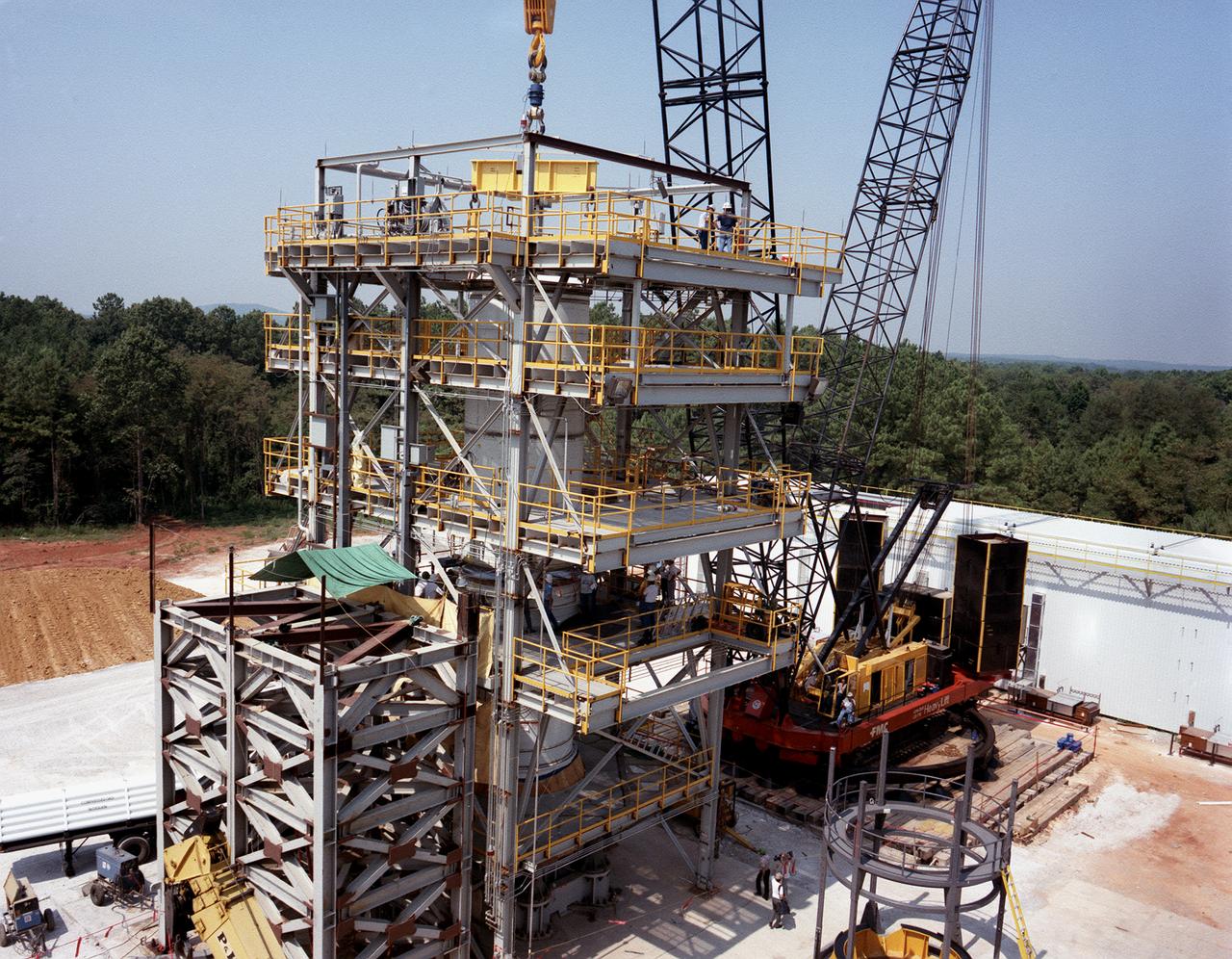
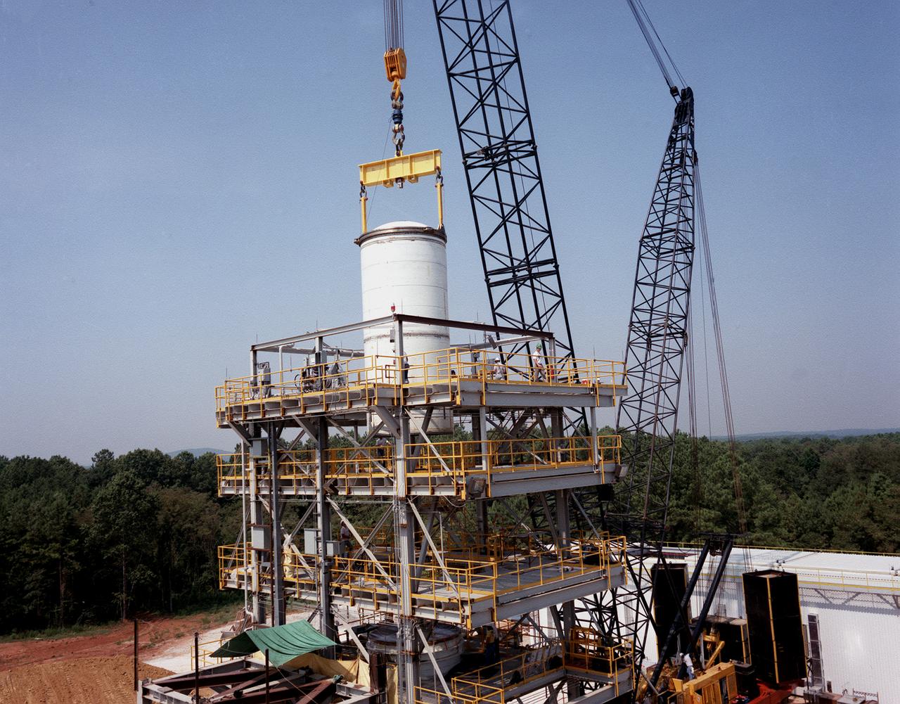
A forward segment is being lowered into the Transient Pressure Test Article (TPTA) test stand at thw Marshall Space Flight Center (MSFC) east test area. The TPTA test stand, 14-feet wide, 27-feet long, and 33-feet high, was built in 1987 to provide data to verify the sealing capability of the redesign solid rocket motor (SRM) field and nozzle joints. The test facility applies pressure, temperature, and external loads to a short stack of solid rocket motor hardware. The simulated SRM ignition pressure and temperature transients are achieved by firing a small amount of specially configured solid propellant. The pressure transient is synchronized with external programmable dynamic loads that simulate lift off loads at the external tank attach points. Approximately one million pounds of dead weight on top of the test article simulates the weight of the other Shuttle elements.
A forward segment is being lowered into the Transient Pressure Test Article (TPTA) test stand at the Marshall Space Flight Center (MSFC) east test area. The TPTA test stand, 14-feet wide, 27-feet long, and 33-feet high, was built in 1987 to provide data to verify the sealing capability of the redesign solid rocket motor (SRM) field and nozzle joints. The test facility applies pressure, temperature, and external loads to a short stack of solid rocket motor hardware. The simulated SRM ignition pressure and temperature transients are achieved by firing a small amount of specially configured solid propellant. The pressure transient is synchronized with external programmable dynamic loads that simulate lift off loads at the external tank attach points. Approximately one million pounds of dead weight on top of the test article simulates the weight of the other Shuttle elements.
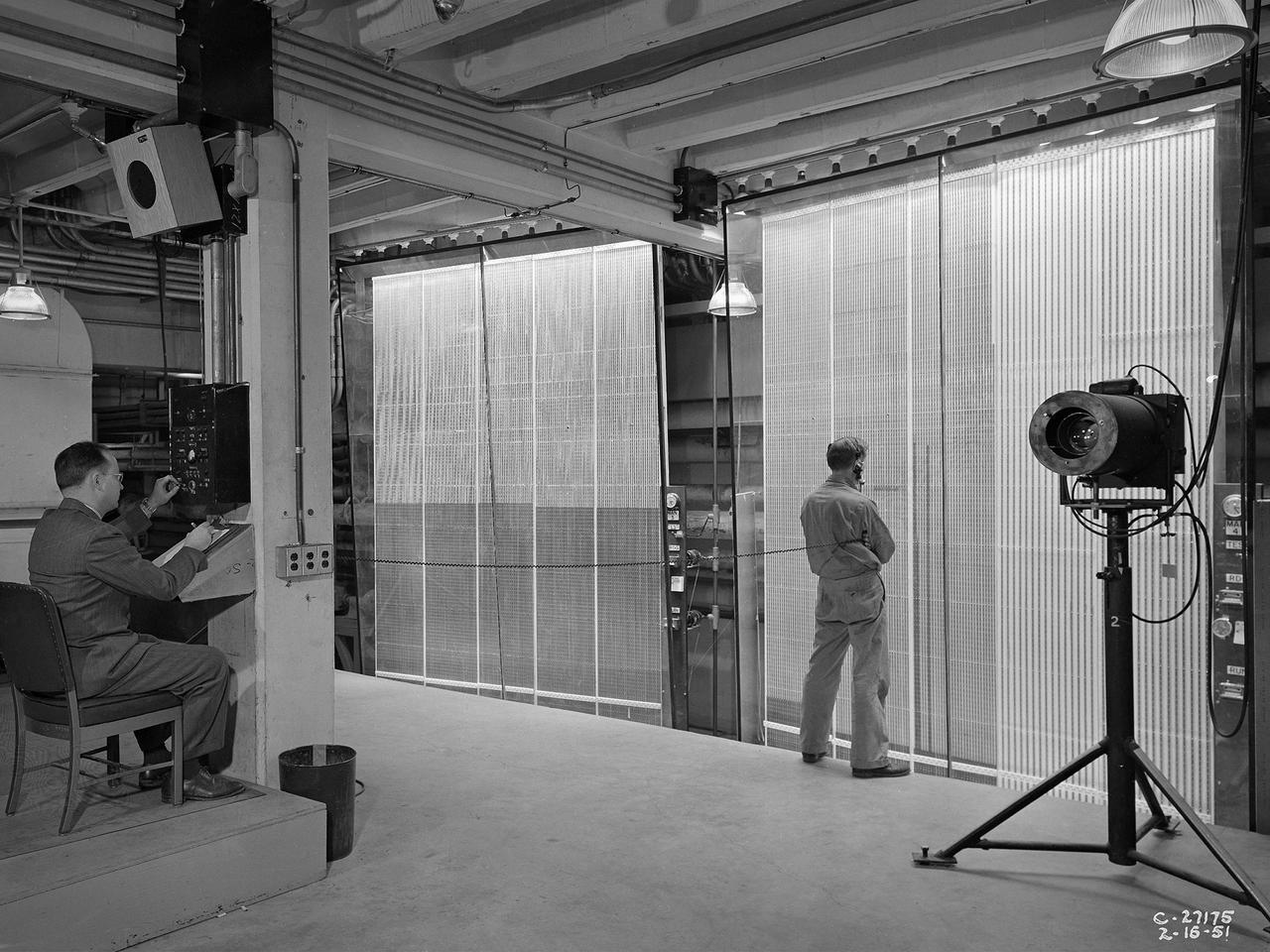
Analysts at the National Advisory Committee for Aeronautics (NACA) Lewis Flight Propulsion Laboratory take data readings from rows of manometers in the basement of the 8- by 6-Foot Supersonic Wind Tunnel. Manometers were mercury-filled glass tubes that indicated different pressure levels in the test section. Manometers look and function very similarly to thermometers. Pressure sensing instruments were installed on the test article inside the wind tunnel or other test facility. Each test could have dozens of such instruments installed and connected to a remotely located manometer tube. The mercury inside the manometer rose and fell with the pressure levels. The dark mercury can be seen at different levels within the tubes. Since the pressure readings were dynamic, it was necessary to note the levels at given points during the test. This was done using both female computers and photography. A camera is seen on a stand to the right in this photograph.
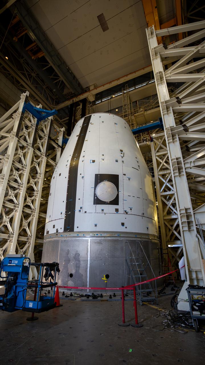
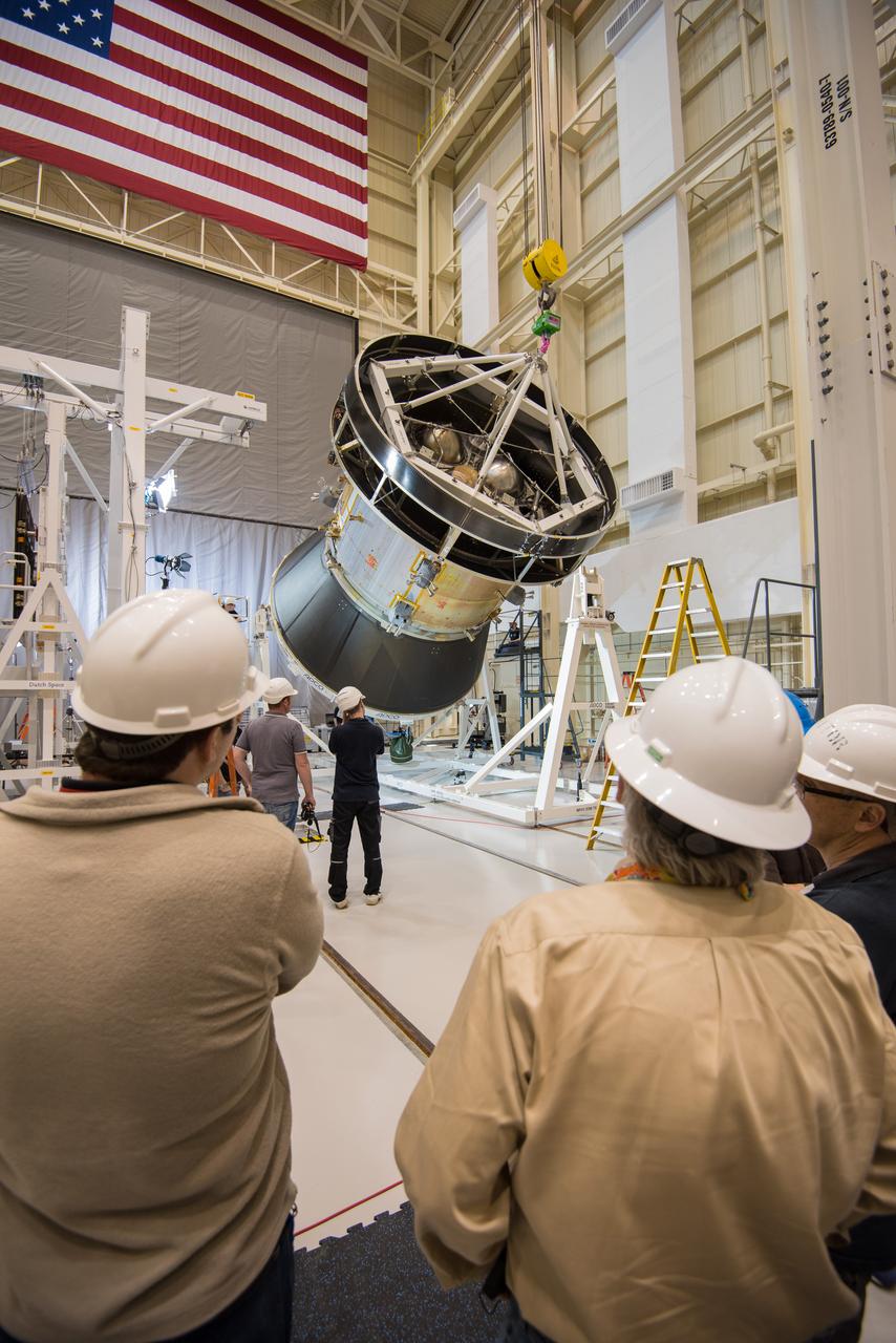
Engineers and technicians at NASA Glenn's Plum Brook Station in Sandusky, Ohio, are preparing for the first major test in the campaign to verify the structural integrity of Orion’s service module for Artemis I, the spacecraft’s first flight atop the agency’s Space Launch System (SLS) rocket. Orion’s service module, which will power and propel the vehicle and supply it with air and water, is being provided by ESA and built by Airbus Defence and Space. The solar array wing deployment test will verify that the qualification model wing unfurls as expected. On Saturday, Feb. 20, an international team of engineers and technicians lifted and tilted the service module test article -- which includes structural representations of the service module, crew module adapter, and spacecraft adapter -- to a 90 degree angle to position it for the deployment test of one of Orion’s four solar arrays. The next step in preparation for the test is attaching the solar array before the Feb. 29 deployment test. This is the first in a series of crucial tests to verify the service module’s structural integrity and ability to withstand the dynamic launch environment atop the SLS rocket.
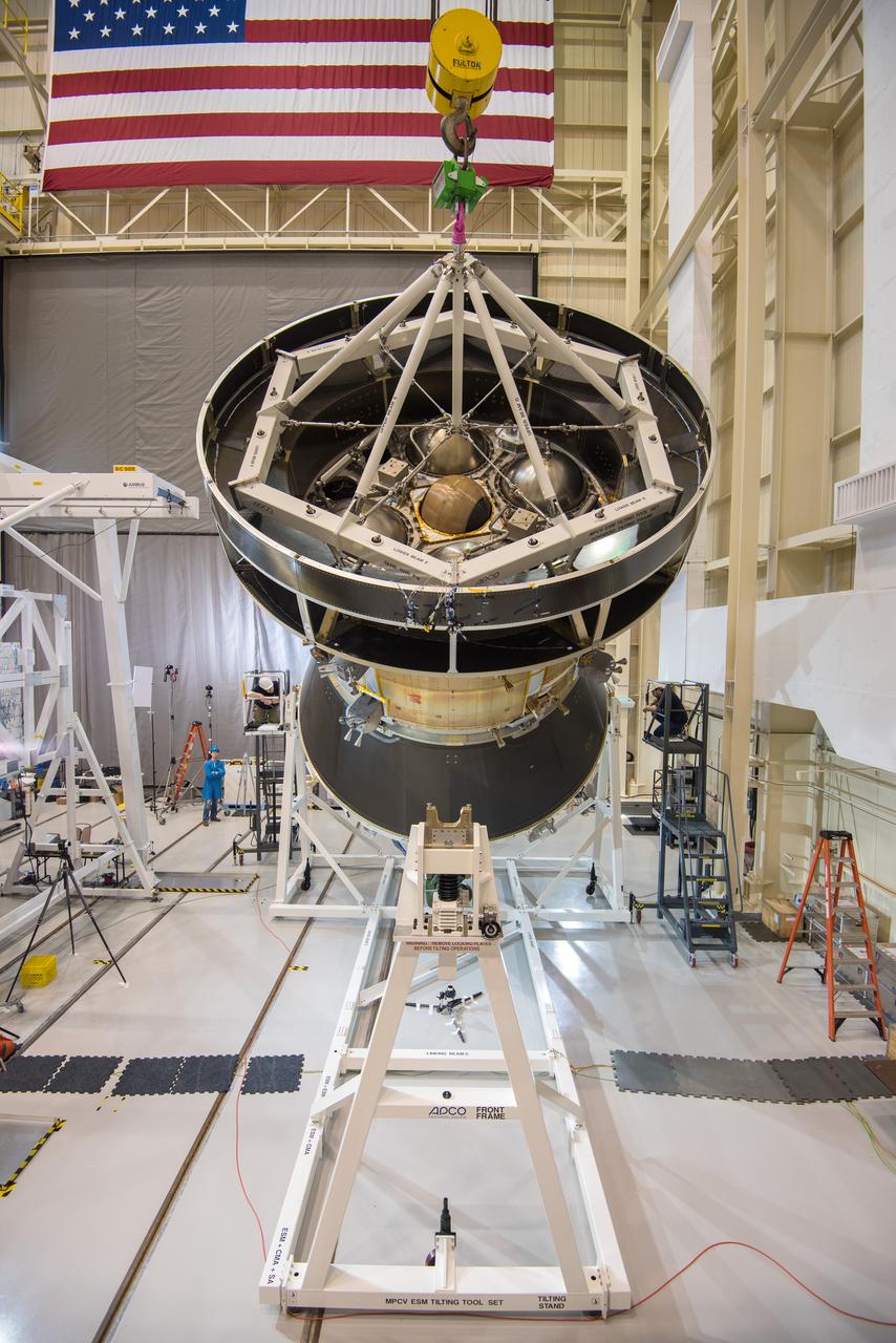
Engineers and technicians at NASA Glenn's Plum Brook Station in Sandusky, Ohio, are preparing for the first major test in the campaign to verify the structural integrity of Orion’s service module for Artemis I, the spacecraft’s first flight atop the agency’s Space Launch System (SLS) rocket. Orion’s service module, which will power and propel the vehicle and supply it with air and water, is being provided by ESA and built by Airbus Defence and Space. The solar array wing deployment test will verify that the qualification model wing unfurls as expected. On Saturday, Feb. 20, an international team of engineers and technicians lifted and tilted the service module test article -- which includes structural representations of the service module, crew module adapter, and spacecraft adapter -- to a 90 degree angle to position it for the deployment test of one of Orion’s four solar arrays. The next step in preparation for the test is attaching the solar array before the Feb. 29 deployment test. This is the first in a series of crucial tests to verify the service module’s structural integrity and ability to withstand the dynamic launch environment atop the SLS rocket.
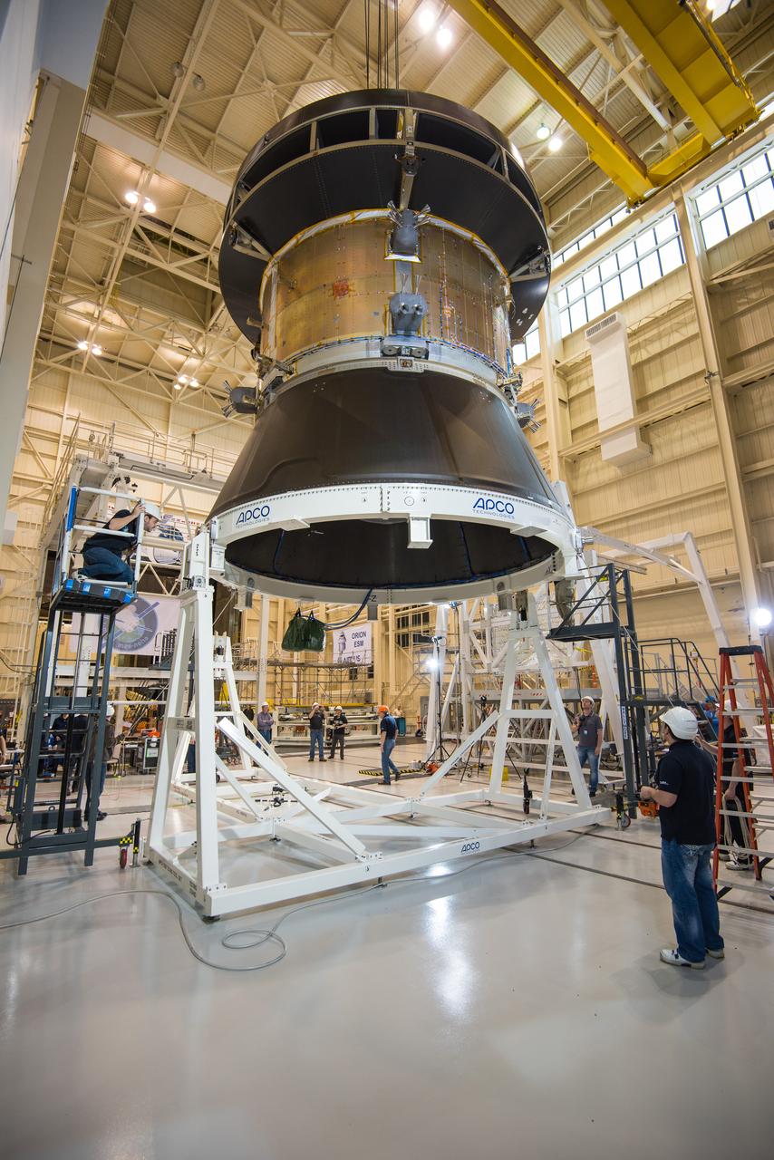
Engineers and technicians at NASA Glenn's Plum Brook Station in Sandusky, Ohio, are preparing for the first major test in the campaign to verify the structural integrity of Orion’s service module for Artemis I, the spacecraft’s first flight atop the agency’s Space Launch System (SLS) rocket. Orion’s service module, which will power and propel the vehicle and supply it with air and water, is being provided by ESA and built by Airbus Defence and Space. The solar array wing deployment test will verify that the qualification model wing unfurls as expected. On Saturday, Feb. 20, an international team of engineers and technicians lifted and tilted the service module test article -- which includes structural representations of the service module, crew module adapter, and spacecraft adapter -- to a 90 degree angle to position it for the deployment test of one of Orion’s four solar arrays. The next step in preparation for the test is attaching the solar array before the Feb. 29 deployment test. This is the first in a series of crucial tests to verify the service module’s structural integrity and ability to withstand the dynamic launch environment atop the SLS rocket.
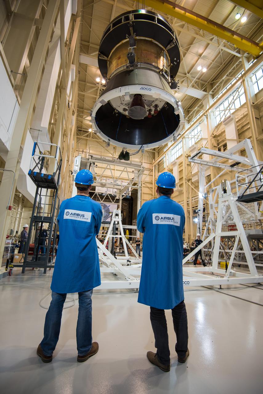
Engineers and technicians at NASA Glenn's Plum Brook Station in Sandusky, Ohio, are preparing for the first major test in the campaign to verify the structural integrity of Orion’s service module for Artemis I, the spacecraft’s first flight atop the agency’s Space Launch System (SLS) rocket. Orion’s service module, which will power and propel the vehicle and supply it with air and water, is being provided by ESA and built by Airbus Defence and Space. The solar array wing deployment test will verify that the qualification model wing unfurls as expected. On Saturday, Feb. 20, an international team of engineers and technicians lifted and tilted the service module test article -- which includes structural representations of the service module, crew module adapter, and spacecraft adapter -- to a 90 degree angle to position it for the deployment test of one of Orion’s four solar arrays. The next step in preparation for the test is attaching the solar array before the Feb. 29 deployment test. This is the first in a series of crucial tests to verify the service module’s structural integrity and ability to withstand the dynamic launch environment atop the SLS rocket.
Engineers and technicians at NASA Glenn's Plum Brook Station in Sandusky, Ohio, are preparing for the first major test in the campaign to verify the structural integrity of Orion’s service module for Artemis I, the spacecraft’s first flight atop the agency’s Space Launch System (SLS) rocket. Orion’s service module, which will power and propel the vehicle and supply it with air and water, is being provided by ESA and built by Airbus Defence and Space. The solar array wing deployment test will verify that the qualification model wing unfurls as expected. On Saturday, Feb. 20, an international team of engineers and technicians lifted and tilted the service module test article -- which includes structural representations of the service module, crew module adapter, and spacecraft adapter -- to a 90 degree angle to position it for the deployment test of one of Orion’s four solar arrays. The next step in preparation for the test is attaching the solar array before the Feb. 29 deployment test. This is the first in a series of crucial tests to verify the service module’s structural integrity and ability to withstand the dynamic launch environment atop the SLS rocket.
Engineers and technicians at NASA Glenn's Plum Brook Station in Sandusky, Ohio, are preparing for the first major test in the campaign to verify the structural integrity of Orion’s service module for Artemis I, the spacecraft’s first flight atop the agency’s Space Launch System (SLS) rocket. Orion’s service module, which will power and propel the vehicle and supply it with air and water, is being provided by ESA and built by Airbus Defence and Space. The solar array wing deployment test will verify that the qualification model wing unfurls as expected. On Saturday, Feb. 20, an international team of engineers and technicians lifted and tilted the service module test article -- which includes structural representations of the service module, crew module adapter, and spacecraft adapter -- to a 90 degree angle to position it for the deployment test of one of Orion’s four solar arrays. The next step in preparation for the test is attaching the solar array before the Feb. 29 deployment test. This is the first in a series of crucial tests to verify the service module’s structural integrity and ability to withstand the dynamic launch environment atop the SLS rocket.
Engineers and technicians at NASA Glenn's Plum Brook Station in Sandusky, Ohio, are preparing for the first major test in the campaign to verify the structural integrity of Orion’s service module for Artemis I, the spacecraft’s first flight atop the agency’s Space Launch System (SLS) rocket. Orion’s service module, which will power and propel the vehicle and supply it with air and water, is being provided by ESA and built by Airbus Defence and Space. The solar array wing deployment test will verify that the qualification model wing unfurls as expected. On Saturday, Feb. 20, an international team of engineers and technicians lifted and tilted the service module test article -- which includes structural representations of the service module, crew module adapter, and spacecraft adapter -- to a 90 degree angle to position it for the deployment test of one of Orion’s four solar arrays. The next step in preparation for the test is attaching the solar array before the Feb. 29 deployment test. This is the first in a series of crucial tests to verify the service module’s structural integrity and ability to withstand the dynamic launch environment atop the SLS rocket.

Engineers and technicians at NASA Glenn's Plum Brook Station in Sandusky, Ohio, are preparing for the first major test in the campaign to verify the structural integrity of Orion’s service module for Artemis I, the spacecraft’s first flight atop the agency’s Space Launch System (SLS) rocket. Orion’s service module, which will power and propel the vehicle and supply it with air and water, is being provided by ESA and built by Airbus Defence and Space. The solar array wing deployment test will verify that the qualification model wing unfurls as expected. On Saturday, Feb. 20, an international team of engineers and technicians lifted and tilted the service module test article -- which includes structural representations of the service module, crew module adapter, and spacecraft adapter -- to a 90 degree angle to position it for the deployment test of one of Orion’s four solar arrays. The next step in preparation for the test is attaching the solar array before the Feb. 29 deployment test. This is the first in a series of crucial tests to verify the service module’s structural integrity and ability to withstand the dynamic launch environment atop the SLS rocket.
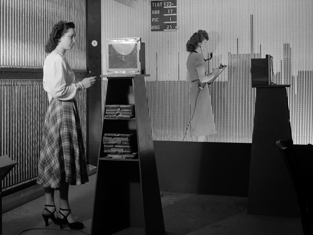
Female computers at the National Advisory Committee for Aeronautics (NACA) Lewis Flight Propulsion Laboratory copy pressure readings from rows of manometers below the 18- by 18-inch Supersonic Wind Tunnel. The computers obtained test data from the manometers and other instruments, made the initial computations, and plotted the information graphically. Based on these computations, the researchers planned their next test or summarized their findings in a report. Manometers were mercury-filled glass tubes that were used to indicate different pressure levels from inside the test facility or from the test article. Manometers look and function very similarly to thermometers. Dozens of pressure sensing instruments were installed for each test. Each was connected to a manometer tube located inside the control room. The mercury inside the manometer rose and fell with the pressure levels. The dark mercury can be seen in this photograph at different levels within the tubes. Since this activity was dynamic, it was necessary to note the levels at given points during the test. This was done using both computer notations and photography.
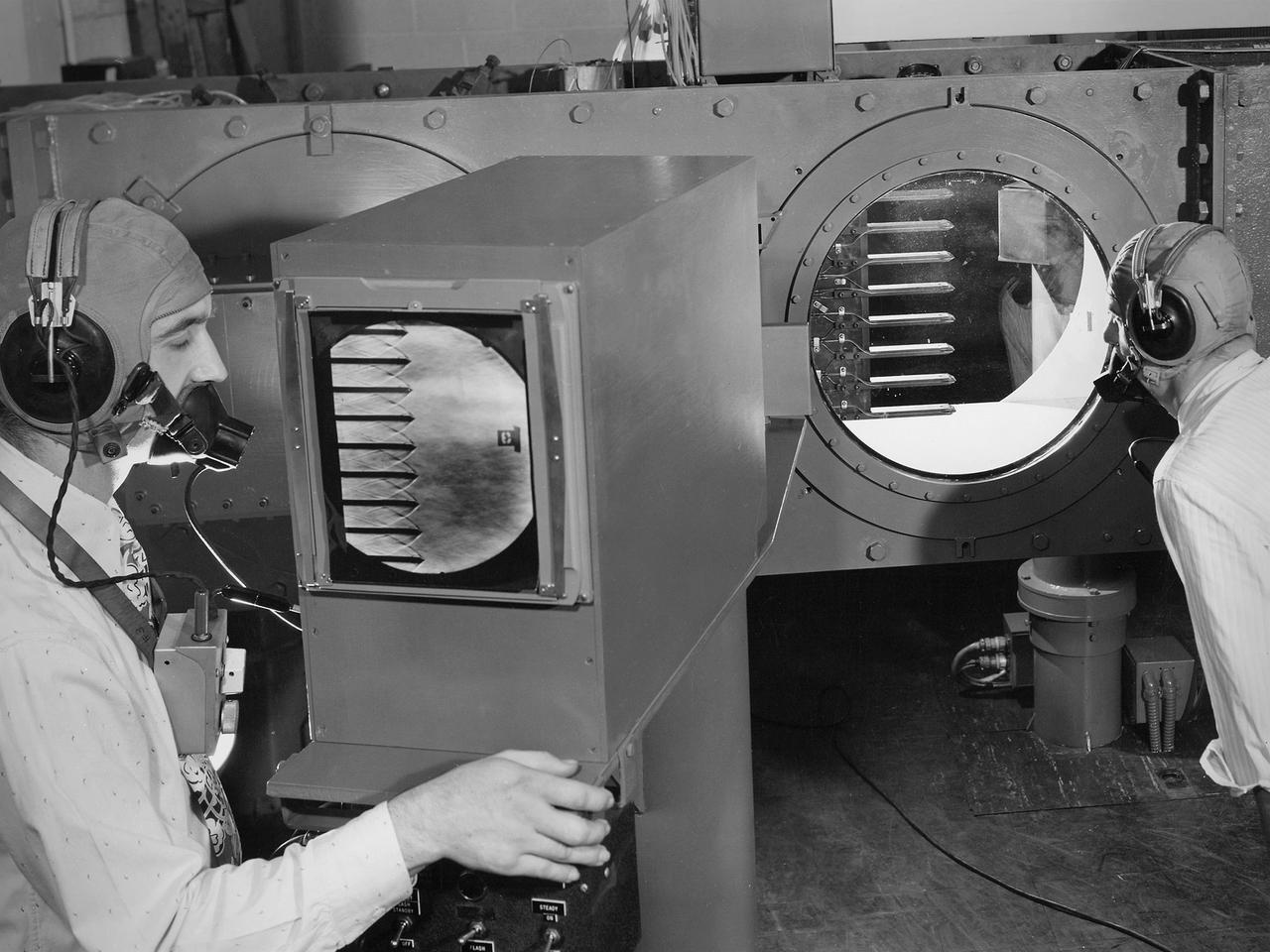
Engineers calibrate one of three small supersonic wind tunnels that were collectively referred to as the “Stack Tunnels” at the National Advisory Committee for Aeronautics (NACA) Lewis Flight Propulsion Laboratory. In late 1945 NACA Lewis reorganized its staff and began constructing a new wave of facilities to address high-speed flight and the turbojet and rocket technologies that emerged during World War II. While design work began on what would eventually become the 8- by 6-Foot Supersonic Wind Tunnel, NACA Lewis quickly built several small supersonic tunnels. These small facilities utilized the Altitude Wind Tunnel’s massive air handling equipment. Three of the small tunnels were built vertically on top of each other and thus were known as the Stack Tunnels. The first of the Stack Tunnels was an 18- by 18-inch tunnel that began operating in August 1945 at speeds up to Mach 1.91. The second tunnel, whose 24- by 24-inch test section is shown here, was added in 1949. It could generate air flows up to Mach 3.96. A third tunnel with an 18- by 18-inch test section began operating in 1951 with speeds up to Mach 3.05. The small tunnels were used until the early 1960s to study the aerodynamic characteristics of supersonic inlets and exits. The technician to the left in this photograph is operating a Schlieren camera to view the air flow dynamics inside the 24- by 24-inch test section. The technician on the right is viewing the pronged test article through the circular window. They are calibrating the tunnel and its equipment to prepare for the initial test runs.