
This concept illustrates Skylab Earth observation studies, an Earth Resources Experiment Package (EREP). EREP was designed to explore the use of the widest possible portion of the electromagnetic spectrum for Earth resource investigations with sensors that recorded data in the visible, infrared, and microwave spectral regions. Resources subject to this study included a capability of mapping Earth resources and land uses, crop and forestry cover, health of vegetation, types of soil, water storage in snow pack, surface or near-surface mineral deposits, sea surface temperature, and the location of likely feeding areas for fish, etc. A significant feature of EREP was the ability of man to operate the sensors in a laboratory fashion.

NASA Dryden life support technician Jim Sokolik assists pressure-suited pilot Dee Porter into the cockpit of NASA's ER-2 Earth resources aircraft.
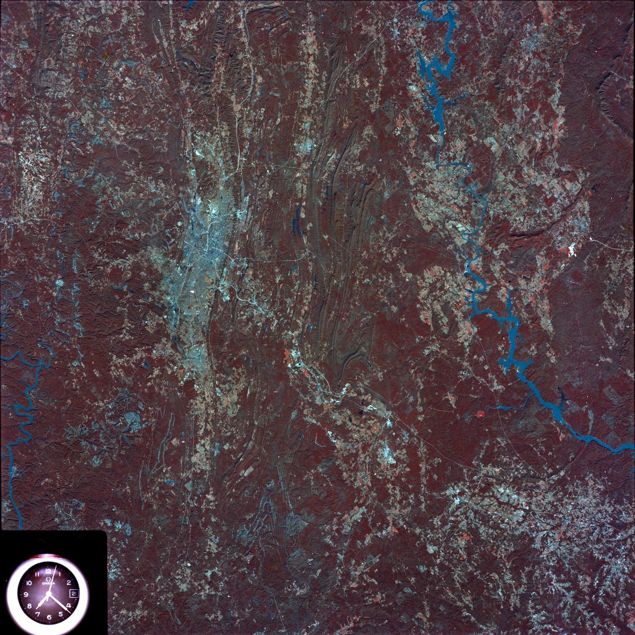
SL4-93-153 (February 1974) --- A vertical view of the Birmingham and central Alabama area is seen in this Skylab 4 Earth Resources Experiments Package S190-B (five-inch earth terrain camera) infrared photographed taken from the Skylab space station in Earth orbit. Illustrated here is the utility of color infrared film in depicting distribution of living vegetation in the 3,600 square mile Birmingham region. The Birmingham industrial complex, with a population of nearly 850,000, is the light gray area nestled in the valley between the northeast-trending ridges that are prominent topographic features in the southern Appalachian Mountains. The narrow ridges and adjacent valleys reflect folded and faulted sedimentary rocks, indicating the complex geological history of the region. Two major rivers and several reservoirs are easily distinguished in this photograph. Bankhand Lake, formed by a dam on the Black Warrior River, appears as bright blue west of Birmingham. Two lakes are formed by dams on the Goosa River east of Birmingham. Federal and state highways appear as thin white lines and are easily identified. Interstate 65 to Montgomery is the prominent white line extending southward from Birmingham. Power line clearings are visible in the center of the picture along the Goosa River, and can be traced northwestward to northern parts of Birmingham. The predominant deep red color of the picture is due to the reflections from living vegetation. In contrast are the light tan areas that commonly occur as rectangular patterns in the east part of the photograph and represent mature agricultural crops or grazing lands. Analysis of the photographic data from the earth terrain camera will be conducted by Dr. H. Jayroe of the Marshall Space Flight Center in developing analytical techniques. All EREP photography is available to the public through the Department of Interior's Earth Resources Observations Systems Data Center, Sioux Falls, South Dakota, 57198. Photo credit: NASA

The large air intakes for its powerful engine are obvious as NASA's high-flying ER-2 #806 Earth resources aircraft taxies out for another science mission.
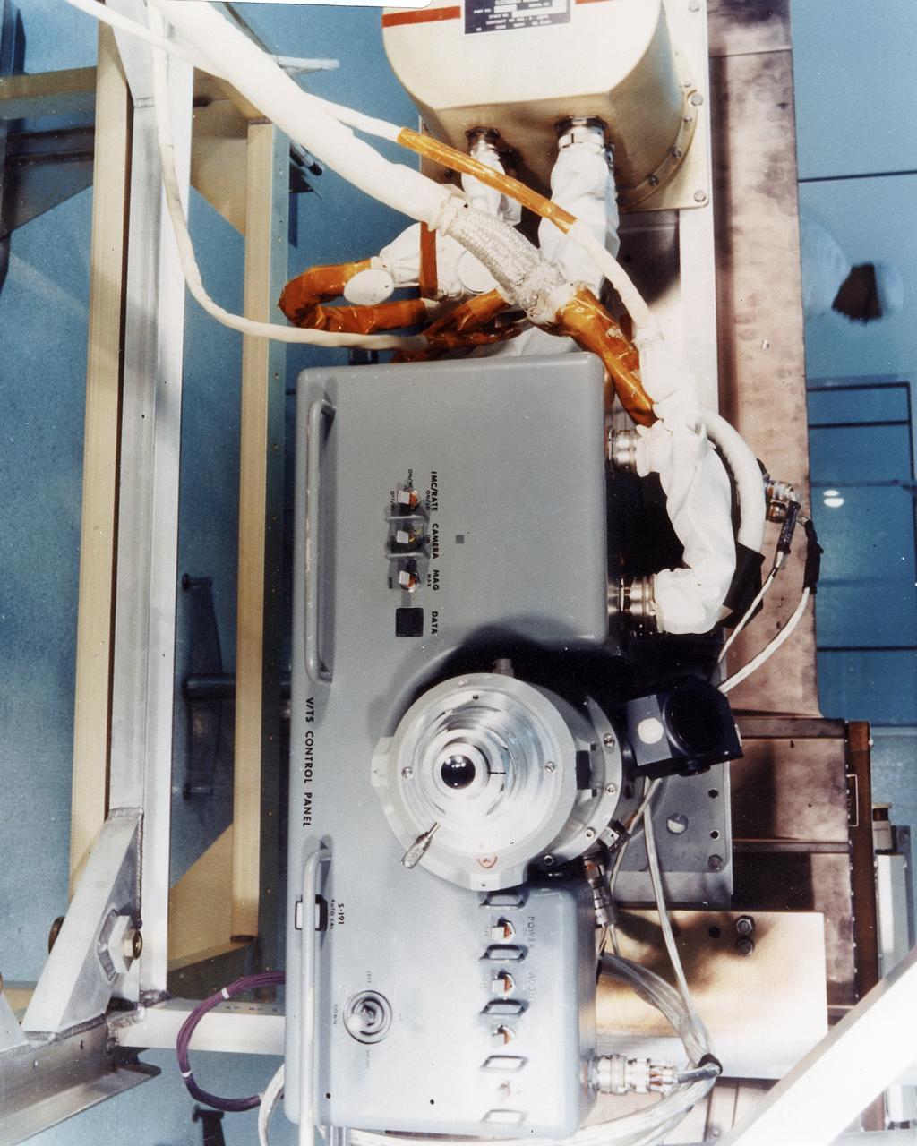
This 1970 photograph shows Skylab's Infrared Spectrometer Viewfinder Tracking System, a major component of an Earth Resources Experiment Package (EREP). It was designed to evaluate Earth resources sensors for specific regions of the the visible and infrared spectra and assess the value of real time identification of ground sites. The overall purpose of the EREP was to test the use of sensors that operated in the visible, infrared, and microwave portions of the electromagnetic spectrum to monitor and study Earth resources. The Marshall Space Flight Center had program management responsibility for the development of Skylab hardware and experiments.

This 1970 photograph shows Skylab's Multispectral Scanner, one of the major components of an Earth Resources Experiment Package (EREP). It was designed to evaluate the on-orbit use of multispectral scanning of Earth resources. Investigators could evaluate the usefulness of spacecraft multispectral data for crop identification, vegetation mapping, soil moisture measurements, identification of contaminated areas in large bodies of water, and surface temperature mapping. The overall purpose of the EREP was to test the use of sensors that operated in the visible, infrared, and microwave portions of the electromagnetic spectrum to monitor and study Earth resources. The Marshall Space Flight Center had program management responsibility for the development of Skylab hardware and experiments.
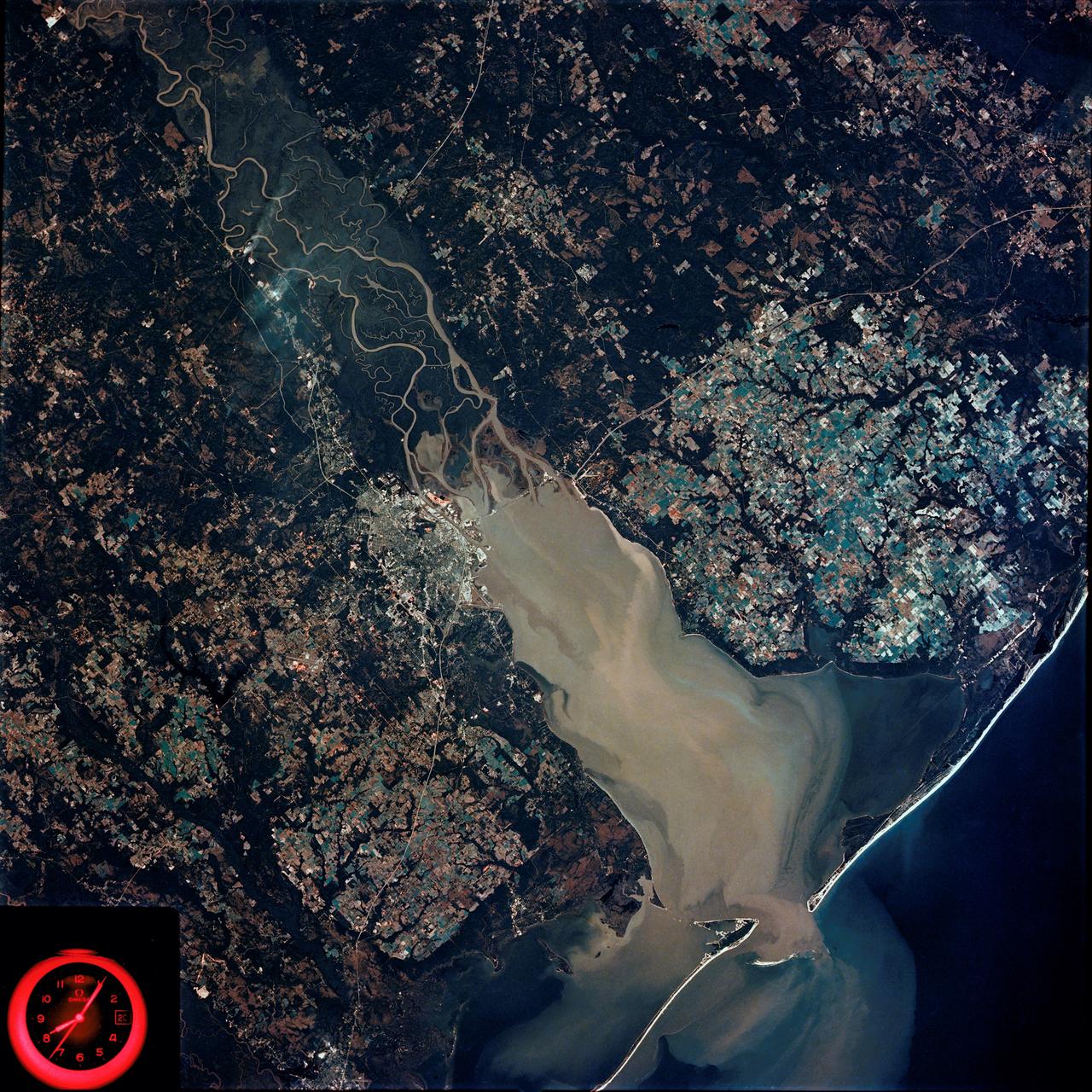
SL4-92-300 (February 1974) --- A near vertical view of the Mobile Bay, Alabama area is seen in this Skylab 4 Earth Resources Experiments Package S190-B (five-inch earth terrain camera) photograph taken from the Skylab space station in Earth orbit. North of Mobile the Tombigbee and Alabama Rivers join to form the Mobile River. Detailed configuration of the individual stream channels and boundaries can be defined as the Mobile River flows into Mobile Bay, and thence into the Gulf of Mexico. The Mobile River Valley with its numerous stream channels is a distinct light shade in contrast to the dark green shade of the adjacent areas. The red coloration of Mobile Bay reflects the sediment load carried into the Bay by the rivers. Variations in red color indicate sediment load and the current paths within Mobile Bay. The waterly movement of the along shore currents at the mouth of Mobile Bay is shown by the contrasting light blue of the sediment-laden current and the blue of the Gulf predominately. Agricultural areas east and west of Mobile Bay are characterized by a rectangular pattern in green to white shades. Color variations may reflect the type and growth cycle of crops. Agricultural areas (light gray-greens) are also clearly visible in other parts of the photograph. Interstate 10 extends from near Pascagoula, Mississippi eastward through Mobile to the outskirts of Pensacola, Florida. Analysis of the EREP photographic data will be undertaken by the U.S. Corps of Engineers to determine bay dynamic processes. Federal agencies participating with NASA on the EREP project are the Departments of Agriculture, Commerce, Interior, the Environmental Protection Agency and the Corps of Engineers. All EREP photography is available to the public through the Department of Interior's Earth Resources Observations Systems Data Center, Sioux Falls, South Dakota. 57198 Photo credit: NASA
This 1970 photograph shows Skylab's Microwave Radiometer/Scatterometer and Altimeter, one of the major components for an Earth Resources Experiment Package (EREP). It was designed to study varying ocean surface, soil erosion, sea and lake ice, snow cover, seasonal vegetational changes, flooding, rainfall and soil types. The overall purpose of the EREP was to test the use of sensors that operated in the visible, infrared, and microwave portions of the electromagnetic spectrum to monitor and study Earth resources. The Marshall Space Flight Center had program management responsibility for the development of Skylab hardware and experiments.
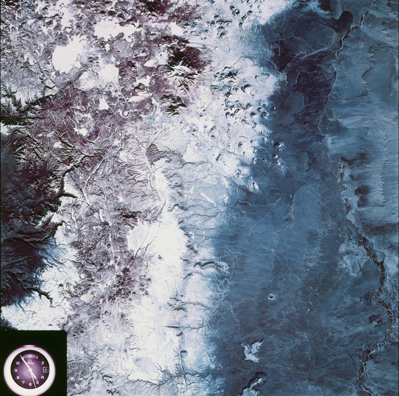
SL4-93-067 (16 Nov. 1973-8 Feb. 1974) --- A spectacular winter view of the Flagstaff, Arizona area is seen in this Skylab 4 Earth Resources Experiments package S190-B (five-inch earth terrain camera) infrared photograph taken from the Skylab space station in Earth orbit. Included in the scene are the San Francisco Mountains, Oak Creek Canyon, Painted Desert and Meteor Crater. The infrared picture depicts in red living vegetation, in white the snow, and in bright blue the water. Major features identified in this photograph are Humphrey's peak, top center, Flagstaff at foot of the peak, Sunset Crater volcanic field with numerous vents and craters right of Flagstaff and Meteor Crater (right center). Within the mountainous areas several clear areas generally rectangular are visible and represent the areas where lumbering has removed the forest. The thin white line extending from left corner to Sunset Crater fields is the power transmission line cleared area. Roads are subdued and are not easily visible. Photo credit: NASA
This Earth Resource Experiment Package (EREP) photograph of the Uncompahgre area of Colorado was electronically acquired in September of 1973 by the Multi-spectral Scarner, Skylab Experiment S192. EREP images were used to analyze the vegetation conditions and landscape characteristic of this area. Skylab's Earth sensors played the dual roles of gathering information about the planet and perfecting instruments and techniques for future satellites and manned stations. An array of six fixed cameras, another for high resolution, and the astronauts' handheld cameras photographed surface features. Other instruments, recording on magnetic tape, measured the reflectivity of plants, soils, and water. Radar measured the altitude of land and water surfaces. The sensors' objectives were to survey croplands and forests, identify soils and rock types, map natural features and urban developments, detect sediments and the spread of pollutants, study clouds and the sea, and determine the extent of snow and ice cover.

NASA Administrator Charles Bolden speaks with young professionals about their project on New England water resources during the annual DEVELOP Earth Science Application Showcase at NASA headquarters Tuesday, August 5, 2014. The Earth Science Applications Showcase highlights the work of over 150 participants in the 10-week DEVELOP program that started in June. The DEVELOP Program bridges the gap between NASA Earth science and society, building capacity in both its participants and partner organizations, to better prepare them to handle the challenges that face our society and future generations. Photo Credit: (NASA/Aubrey Gemignani)
NASA Landsat 1 originally named the Earth Resources Technology Satellite, or ERTS was the first of what was to become a series of satellites designed to map and monitor the Earth land surfaces.
One of NASA's two ER-2 Earth resources aircraft shows off its lines during a flyover at the Edwards Air Force Base open house Oct. 28-29, 2006.
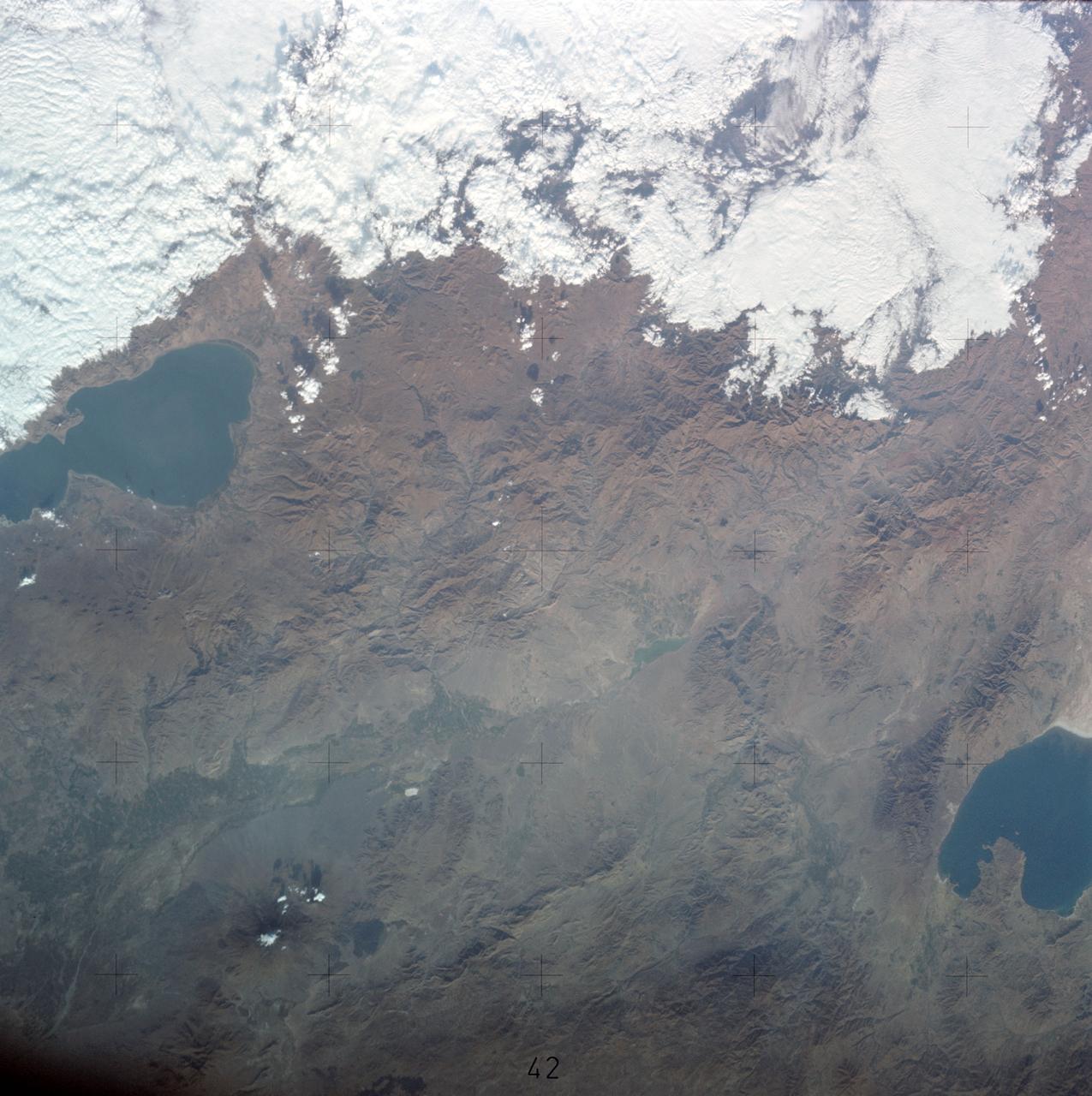
SL3-122-2562 (July-September 1973) --- A near vertical view of the border area of Turkey-Iran?Union of Soviet Socialist Republics as seen from the Skylab space station in Earth orbit. This picture was taken by one of the Skylab 3 crewmen using a hand-held 70mm Hasselblad camera. THE PICTURE SHOULD BE HELD WITH THE MASS OF WHITE CLOUDS ON THE RIGHT SIDE. The lake at the top center edge is Ozero (Lake) Sevan in the USSR?s Armenian Soviet Socialist Republic. The other body of water is Iran?s Lake Urmia. The major feature in this photograph can be seen in the upper left corner. Mount Ararat is in Turkey only a few miles from Iran and USSR borders. Yerevan, the capital of Armenian SSR, is located north-northwest of Mount Ararat. Photo credit: NASA
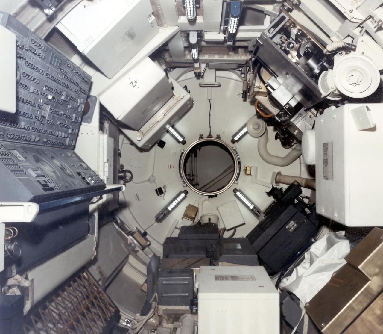
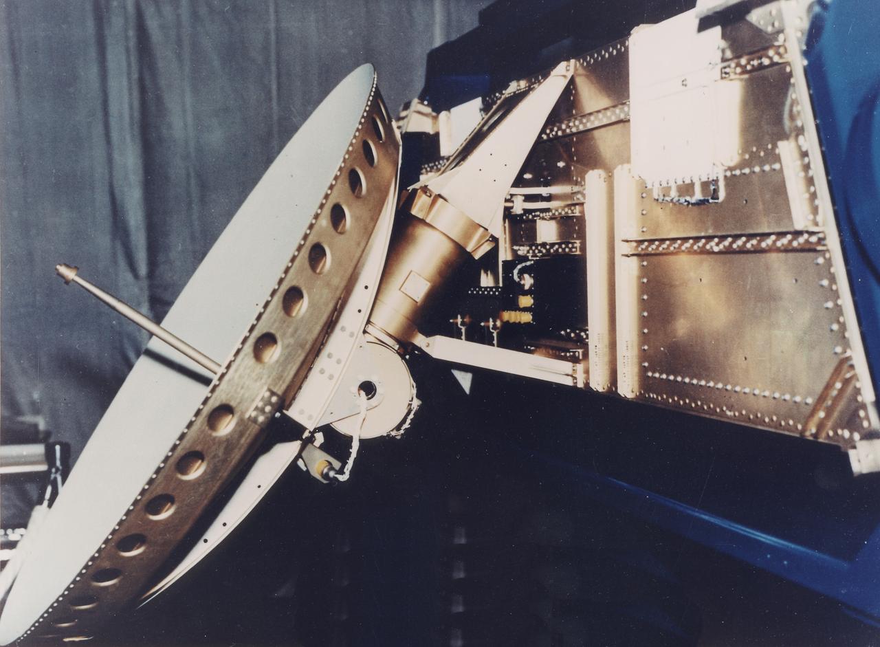
This interior photograph of Skylab's multiple docking adapter (MDA) flight article, then undergoing outfitting at the Martin Marietta Corporation's Space Center facility in Denver, Colorado, shows the forward cone area and docking turnel (center) that attached to the Apollo Command Module. Designed and manufactured by the Marshall Space Flight Center, the MDA housed the control units for the Apollo Telescope Mount (ATM), Earth Resources Experiment Package (EREP), and Zero-Gravity Materials Processing Facility and provided a docking port for the Apollo Command Module.
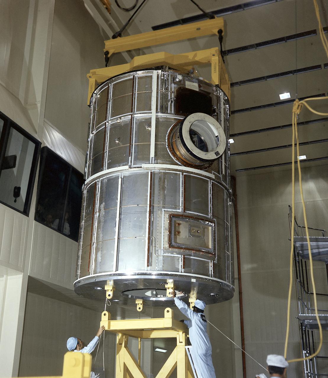
At Marshall Space Flight Center, Skylab's Multiple Docking Adapter (MDA) flight article undergoes center-of-gravity testing. Developed and fabricated by MSFC, the MDA housed the control units for the Apollo Telescope Mount (ATM), Earth Resources Experiment Package (EREP), and the Zero-Gravity Material Processing Facility and provided a docking port for the Apollo Command Module.
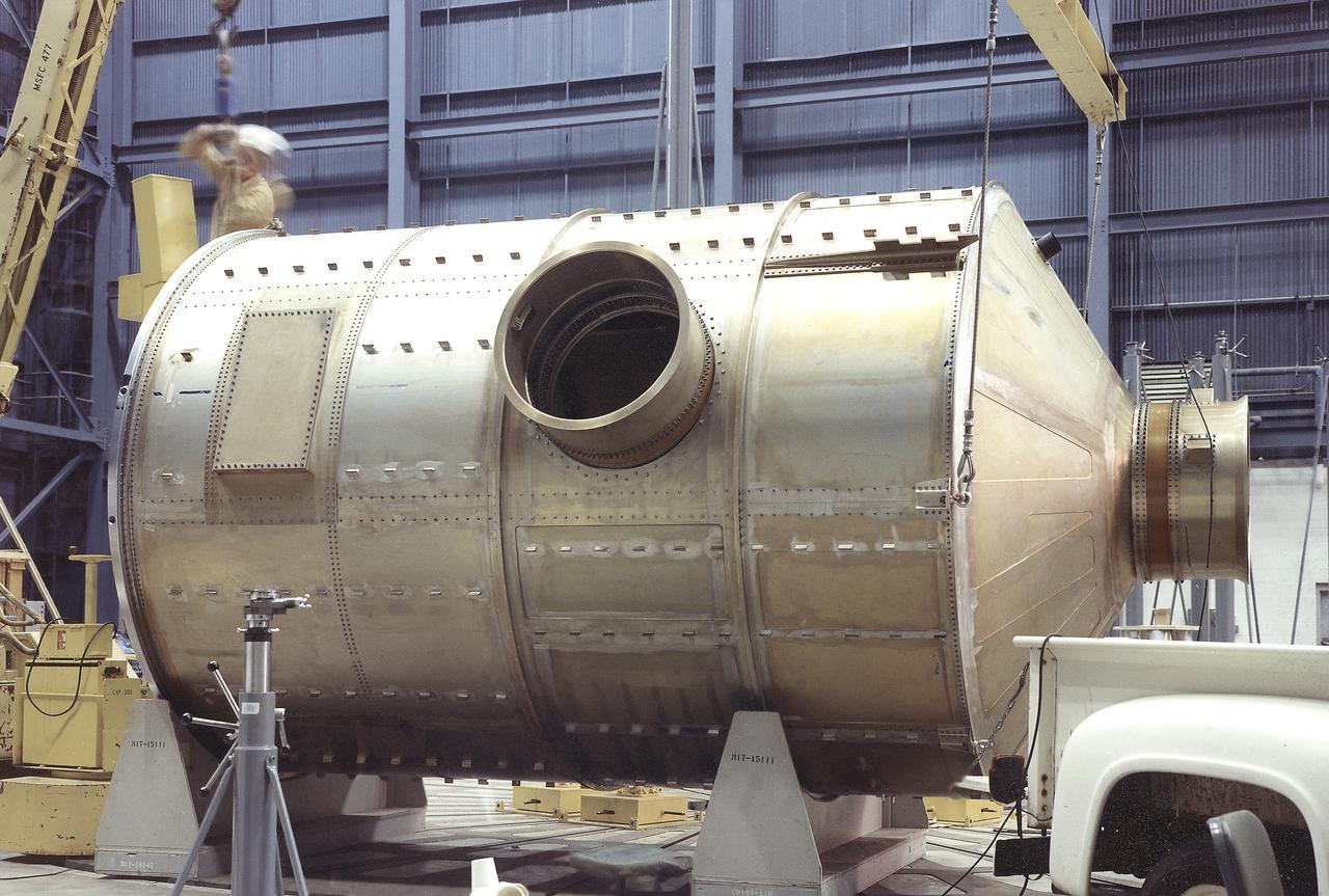
Workmen at the Martin Marietta Corporation's Space Center in Denver, Colorado, position Skylab's Multiple Docking Adapter (MDA) flight article in the horizontal transportation fixture. Designed and manufactured by the Marshall Space Flight Center and outfitted by Martin Marietta, the MDA housed the control units for the Apollo Telescope Mount (ATM), Earth Resources Experiment Package (EREP), and Zero-Gravity Materials Processing Facility and provided a docking port for the Apollo Command Module.
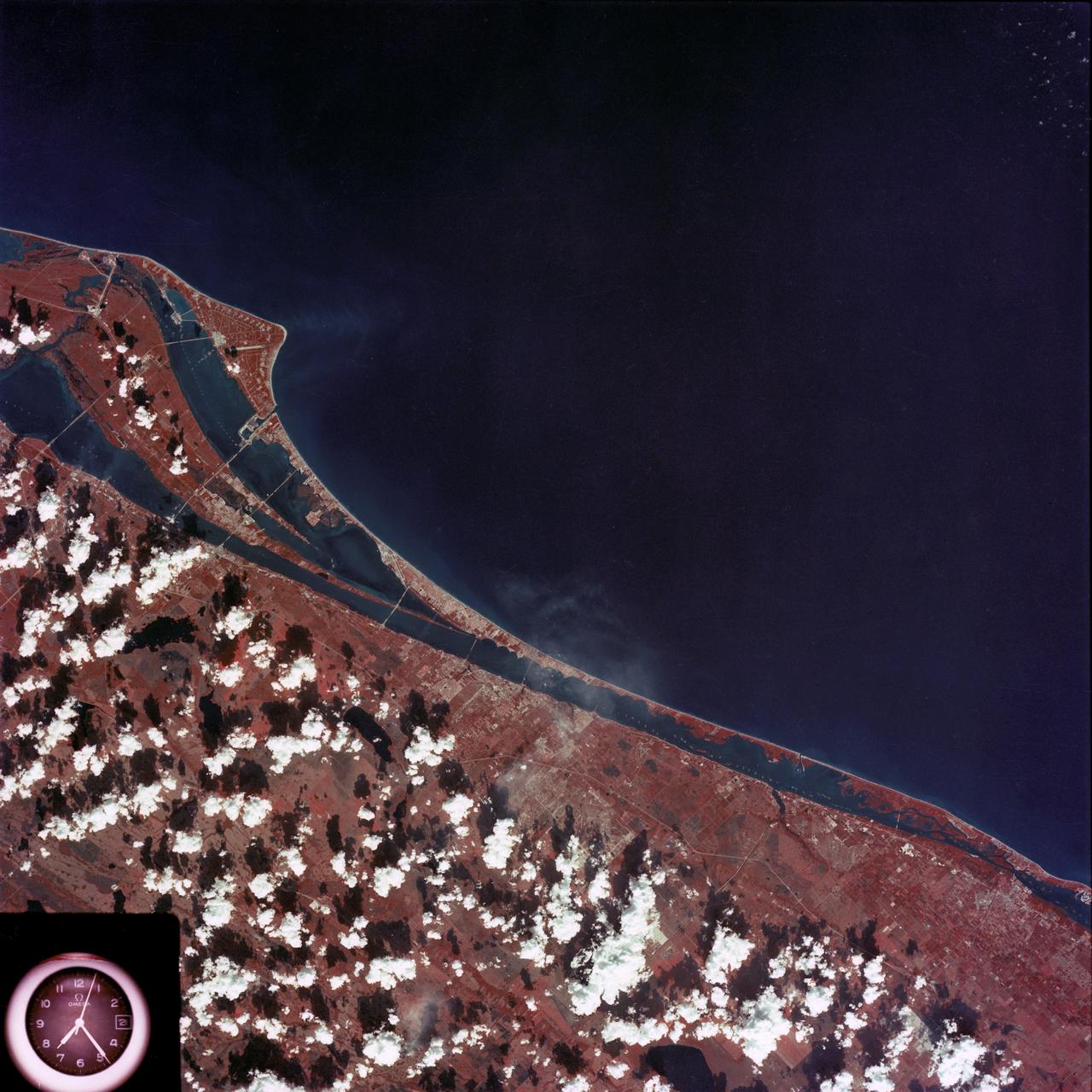
SL4-93-167 (February 1974) --- A vertical view of the Kennedy Space Center and the Florida Atlantic coast area is seen in this Skylab 4 Earth Resources Experiments Package S190-B (five-inch earth terrain camera) infrared photography taken from the Skylab space station in Earth orbit. This photograph shows the major land-ocean features of the Florida coast near Vero Beach northward to Cape Canaveral and the KSC complex. The launch pads for the Skylab missions are clearly visible. Identification of living vegetation is possible through the use of the color infrared film. Various shades of red portray differences in the vegetation such as shown in the patterns in the agricultural area near Vero Beach. In the Kennedy Space Center, the nearly continuous and uniform red color shows that most of the land areas are heavily vegetated. The white coastal beach areas are strongly contrasted to the red land and the blue Atlantic Ocean. Old dunal areas in KSC are visible on Merritt Island which is separated from the Launch areas by the Banana River and the mainland by the Indian River. Federal and state highways and numerous causeways over the rivers are easily identified. The Florida mainland is partly shadowed by small white clouds which cast a pronounced shadow to the east of each cloud indicated the Sun is west of solar noon. Federal agencies participating with NASA on the EREP project are the Departments of Agriculture, Commerce, Interior, the Environmental Protection Agency and the Core of Engineers. All EREP photography is available to the public through the Department of Interior's Earth Resources Observations Systems Data Center, Sioux Falls, South Dakota, 57198. Photo credit: NASA
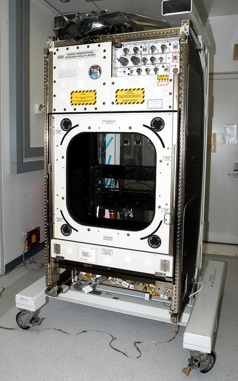
KENNEDY SPACE CENTER, FLA. - The Window Observational Research Facility (WORF), seen in the Space Station Processing Facility, was designed and built by the Boeing Co. at NASA’s Marshall Space Flight Center in Huntsville, Ala. WORF will be delivered to the International Space Station and placed in the rack position in front of the Destiny lab window, providing locations for attaching cameras, multi-spectral scanners and other instruments. WORF will support a variety of scientific and commercial experiments in areas of Earth systems and processes, global ecological changes in Earth’s biosphere, lithosphere, hydrosphere and climate system, Earth resources, natural hazards, and education. After installation, it will become a permanent focal point for Earth Science research aboard the space station.
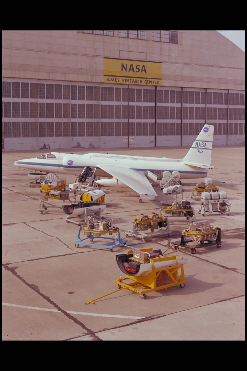
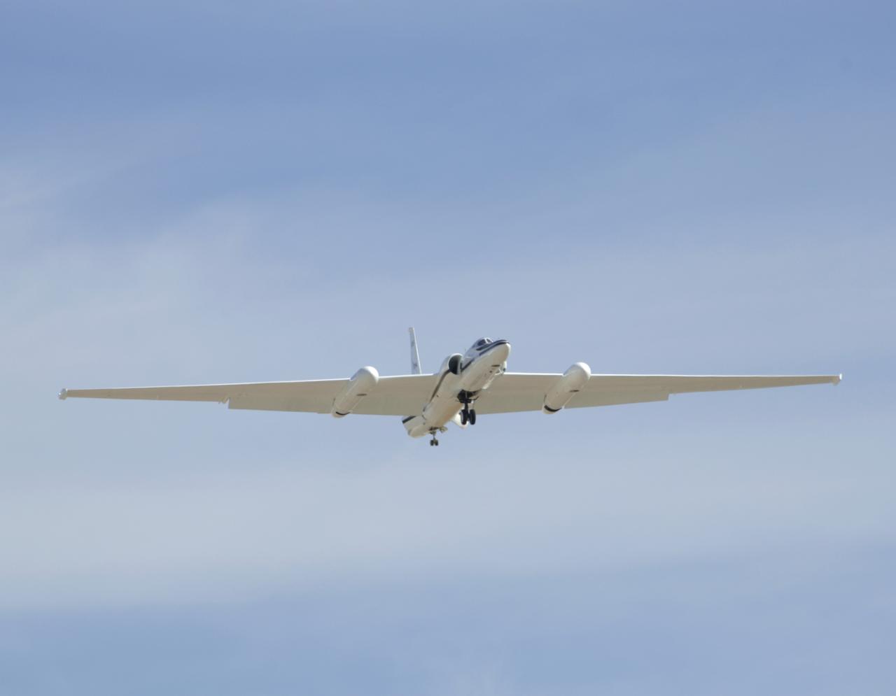
The U-2 Earth Resources Aircraft on the Ames tarmack surrounded by the on board sensors and camera systems
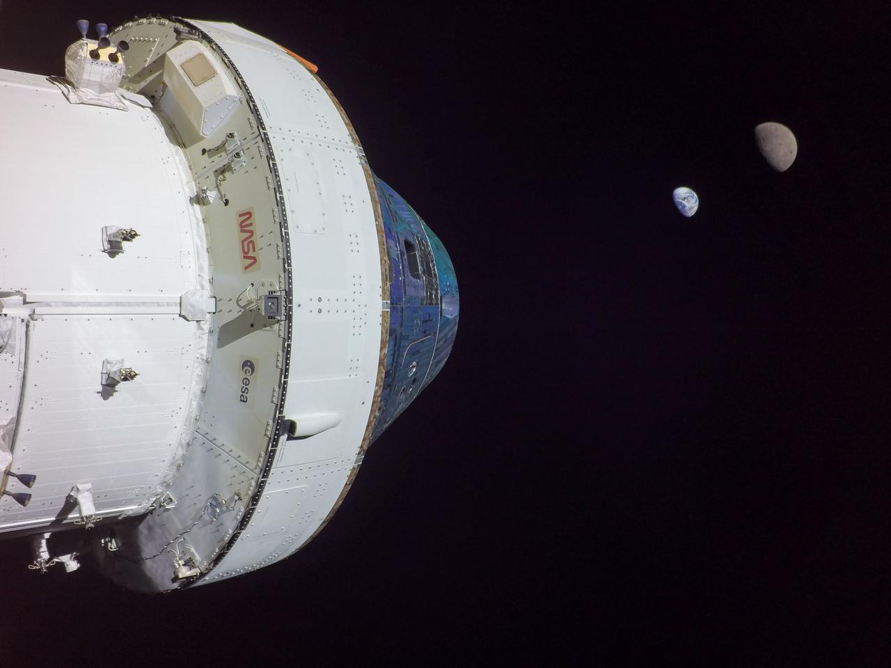
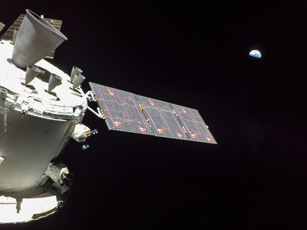
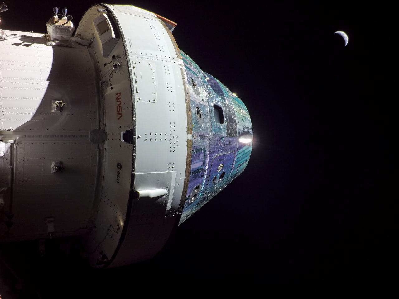
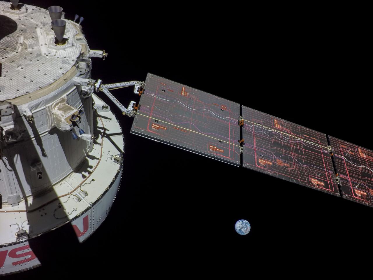
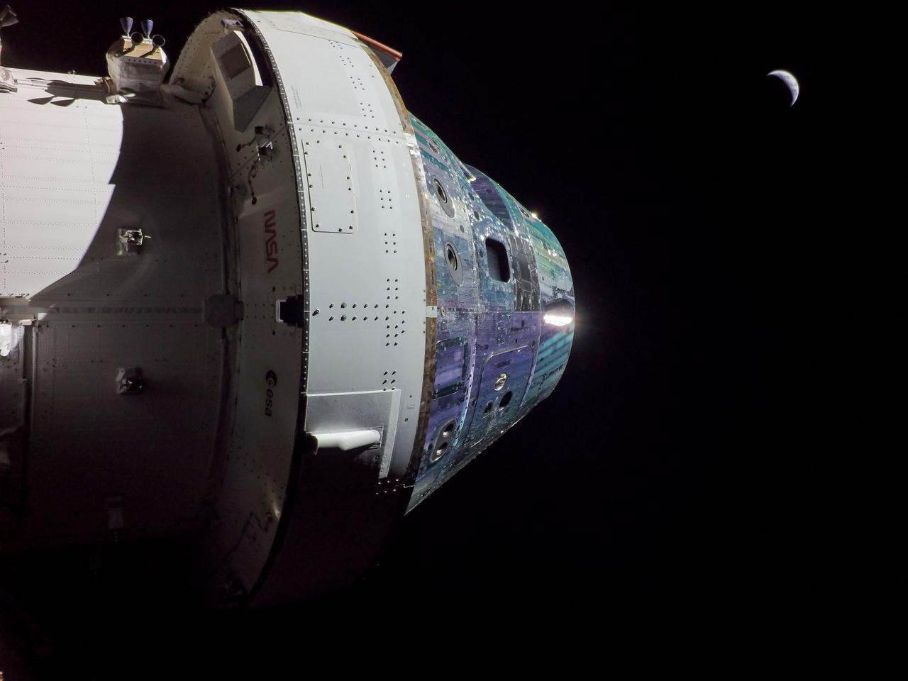
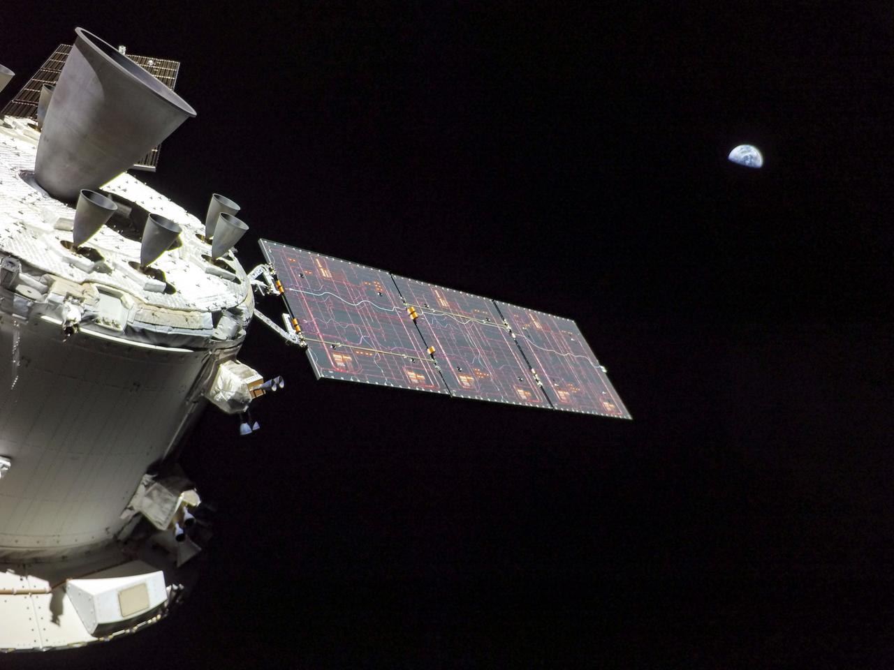
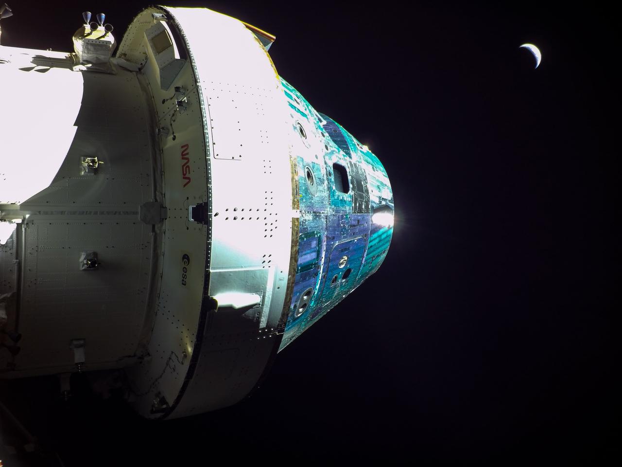
art001e000678 (Nov. 28, 2022) On flight day 13, Orion reached its maximum distance from Earth during the Artemis I mission when it was 268,563 miles away from our home planet. Orion has now traveled farther than any other spacecraft built for humans. The ESA (European Space Agency) logo can be seen in these photos on the European Service Module. This is ESA’s contribution to Orion and includes the large main engine on Orion, the Orbital Maneuvering System engine.
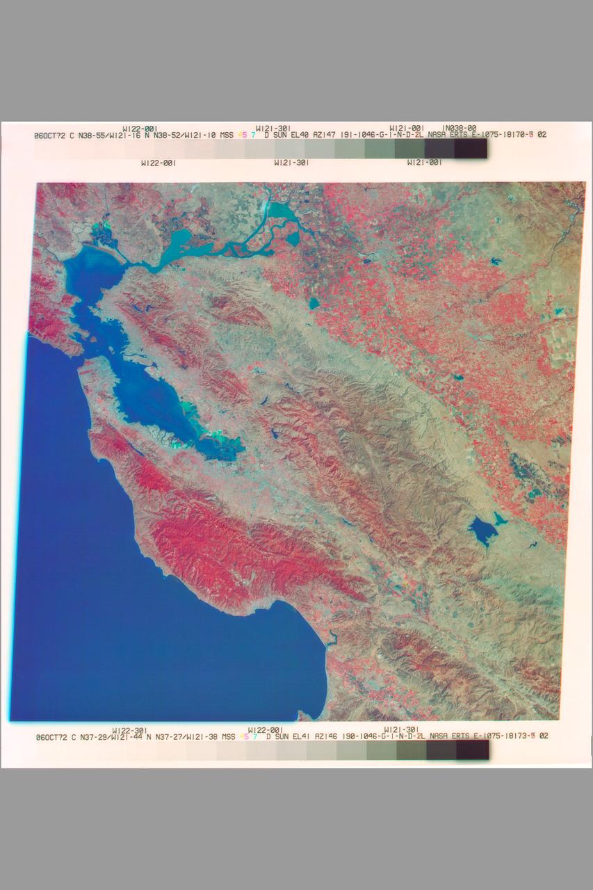
San Francisco Bay Area as seen by NASA Earth Resources Technology Satellite (ERTS) Ref E-1075-18178-3 02)
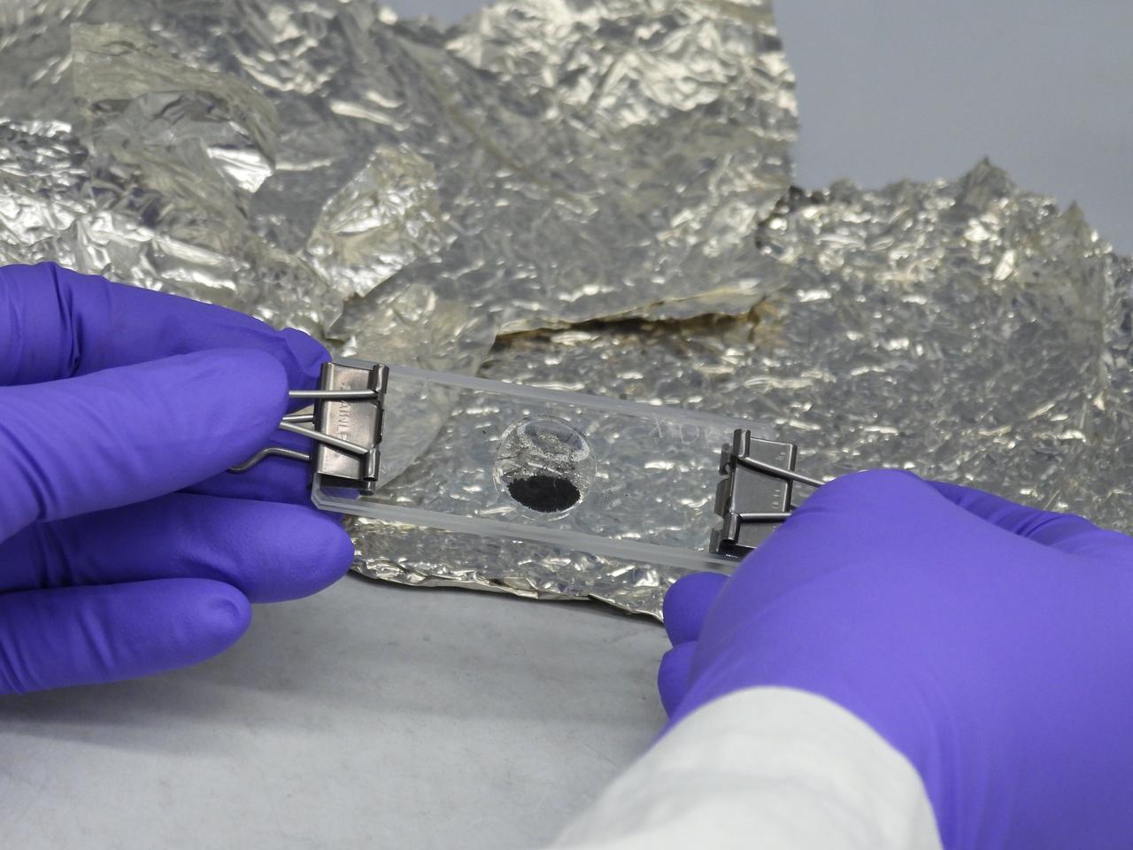
A portion of the asteroid Bennu sample delivered to Earth by NASA's OSIRIS-REx (Origins, Spectral Interpretation, Resource Identification, and Security – Regolith Explorer) mission, set into a microscope slide at the agency's Goddard Space Flight Center in Greenbelt, Maryland.
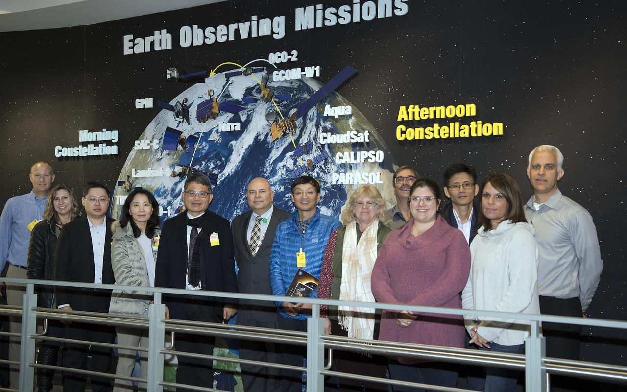
Mr. Lai Chien-Hsin, Director Genreal of Taiwan’s Water Resources Agency and staff US Bureau of Reclamation visited Goddard November 15, 2018 They toured Hyperwall and Earth Sciences facilities
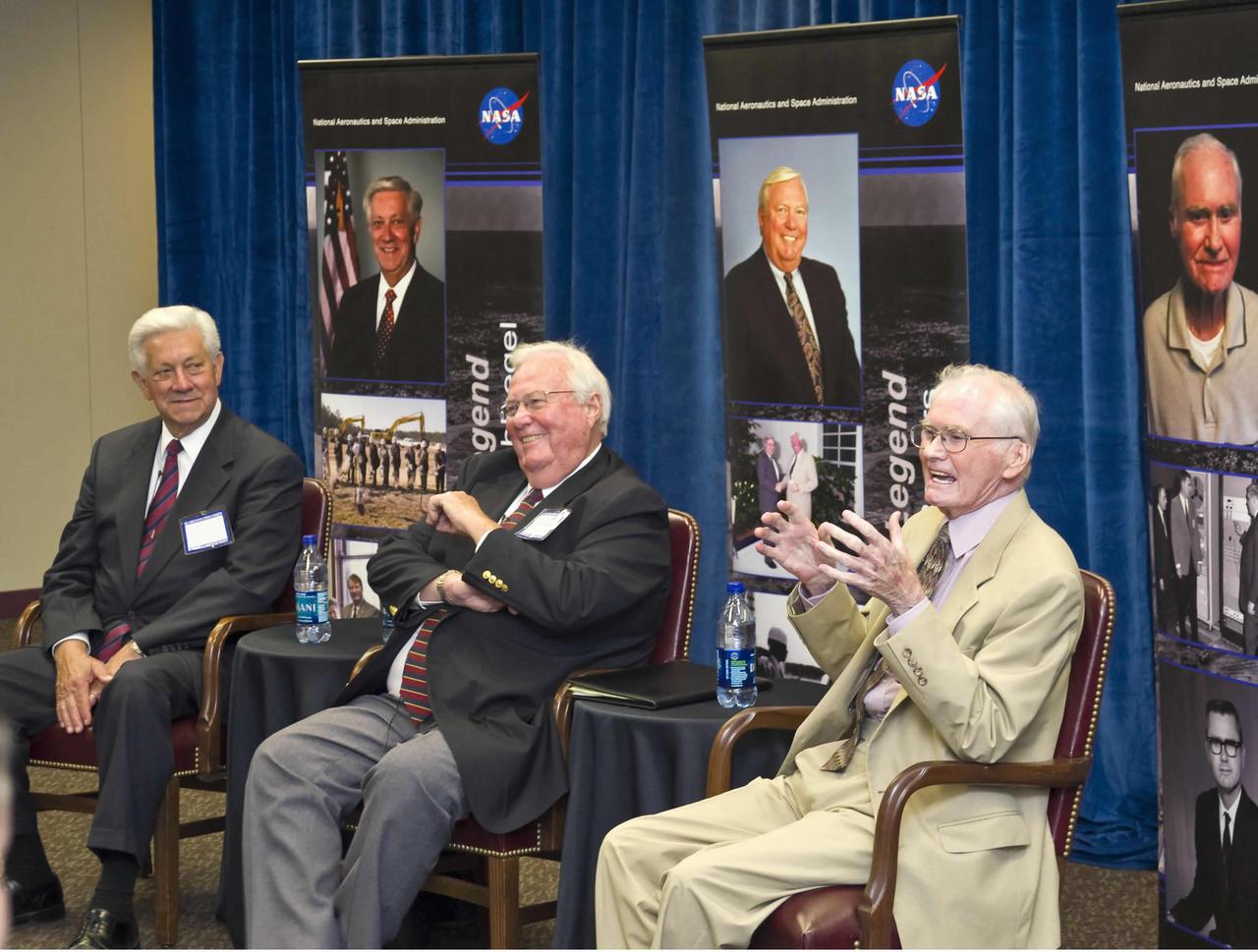
Current and former leaders discuss the growth of NASA's John C. Stennis Space Center during a Legends Lecture Series onsite on April 5. Stennis launched the Legends Lecture Series last November as part of a yearlong celebration of its 50th anniversary. The April 5 session focused on growth of Stennis into a unique federal city during the 1970s and the establishment of NASA's Earth Resources Laboratory at the site. Presenters at the April 5 event included (l to r): George Schloegel, mayor of Gulfport; Jack Rogers, former director of NASA Center Operations at Stennis; and Wayne Mooneyhan, former director of NASA's Earth Resources Laboratory at Stennis.

Current and former leaders discuss the growth of NASA's John C. Stennis Space Center during a Legends Lecture Series onsite on April 5. Stennis launched the Legends Lecture Series last November as part of a yearlong celebration of its 50th anniversary. The April 5 session focused on growth of Stennis into a unique federal city during the 1970s and the establishment of NASA's Earth Resources Laboratory at the site. Presenters at the April 5 event included (l to r): George Schloegel, mayor of Gulfport; Jack Rogers, former director of NASA Center Operations at Stennis; and Wayne Mooneyhan, former director of NASA's Earth Resources Laboratory at Stennis.
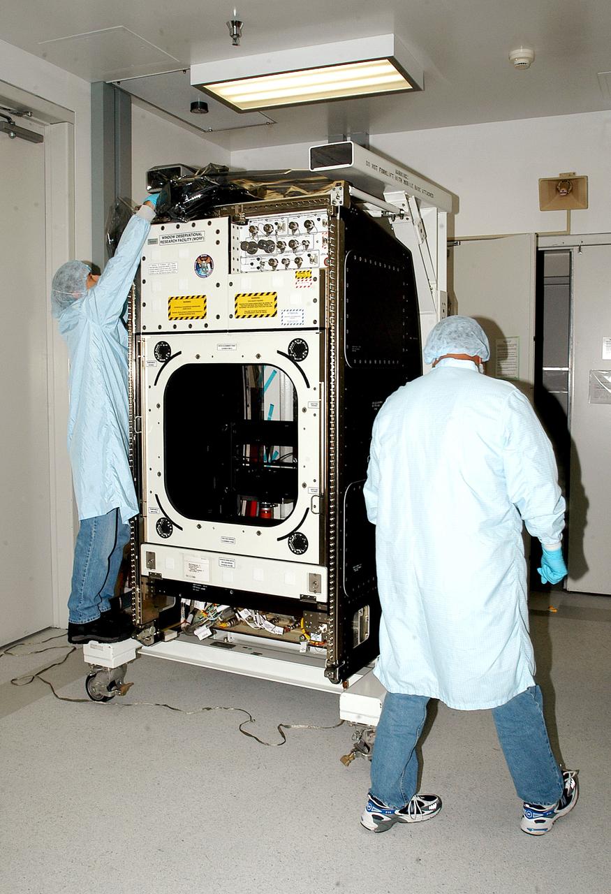
KENNEDY SPACE CENTER, FLA. - Workers in the Space Station Processing Facility check out the Window Observational Research Facility (WORF), designed and built by the Boeing Co. at NASA’s Marshall Space Flight Center in Huntsville, Ala. WORF will be delivered to the International Space Station and placed in the rack position in front of the Destiny lab window, providing locations for attaching cameras, multi-spectral scanners and other instruments. WORF will support a variety of scientific and commercial experiments in areas of Earth systems and processes, global ecological changes in Earth’s biosphere, lithosphere, hydrosphere and climate system, Earth resources, natural hazards, and education. After installation, it will become a permanent focal point for Earth Science research aboard the space station.
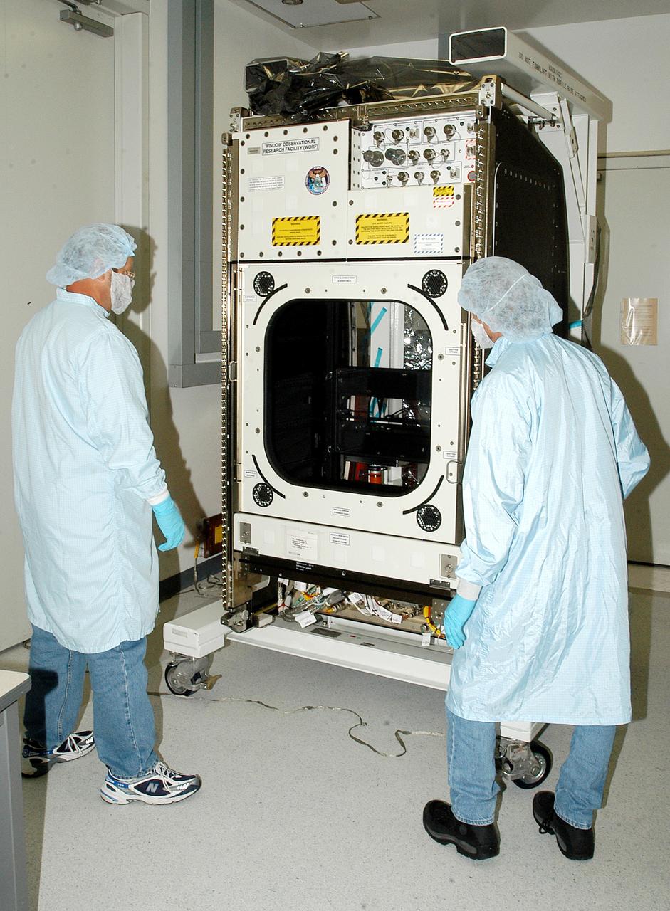
KENNEDY SPACE CENTER, FLA. - Workers in the Space Station Processing Facility check out the Window Observational Research Facility (WORF), designed and built by the Boeing Co. at NASA’s Marshall Space Flight Center in Huntsville, Ala. WORF will be delivered to the International Space Station and placed in the rack position in front of the Destiny lab window, providing locations for attaching cameras, multi-spectral scanners and other instruments. WORF will support a variety of scientific and commercial experiments in areas of Earth systems and processes, global ecological changes in Earth’s biosphere, lithosphere, hydrosphere and climate system, Earth resources, natural hazards, and education. After installation, it will become a permanent focal point for Earth Science research aboard the space station.

This is an image of equatorial Africa, centered on the equator at longitude 15degrees east. This image is a mosaic of almost 4,000 separate images obtained in 1996 by the L-band imaging radar onboard the Japanese Earth Resources Satellite. Using radar to penetrate the persistent clouds prevalent in tropical forests, the Japanese Earth Resources Satellite was able for the first time to image at high resolution this continental scale region during single flooding seasons. The area shown covers about 7.4 million square kilometers (2.8 million square miles) of land surface, spans more than 5,000 kilometers(3,100 miles) east and west and some 2,000 kilometers (1,240 miles) north and south. North is up in this image. At the full resolution of the mosaic (100 meters or 330 feet), this image is more than 500 megabytes in size, and was processed from imagery totaling more than 60 gigabytes. Central Africa was imaged twice in 1996, once between January and March, which is the major low-flood season in the Congo Basin, and once between October and November, which is the major high-flood season in the Congo Basin. The red color corresponds to the data from the low-flood season, the green to the high-flood season, and the blue to the "texture" of the low-flood data. The forests appear green as a result, the flooded and palm forests, as well as urban areas, appear yellow, the ocean and lakes appear black, and savanna areas appear blue, black or green, depending on the savanna type, surface topography and other factors. The areas of the image that are black and white were mapped only between January and March 1996. In these areas, the black areas are savanna or open water, the gray are forests, and the white areas are flooded forests or urban areas. The Congo River dominates the middle of the image, where the nearby forests that are periodically flooded by the Congo and its tributaries stand out as yellow. The Nile River flows north from Lake Victoria in the middle right of the color portion of the mosaic. http://photojournal.jpl.nasa.gov/catalog/PIA01348
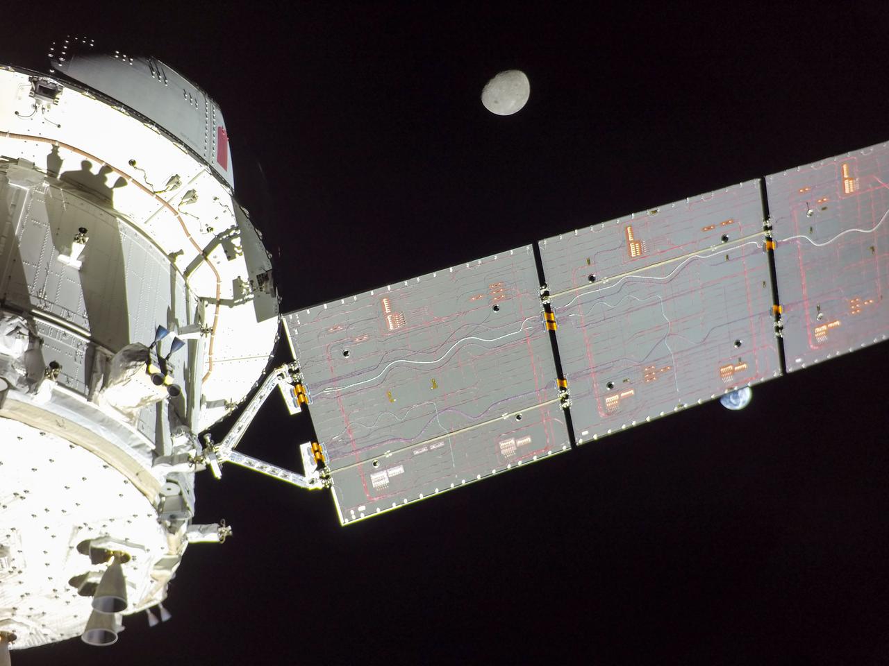
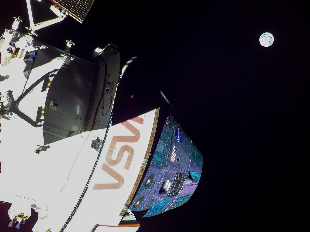
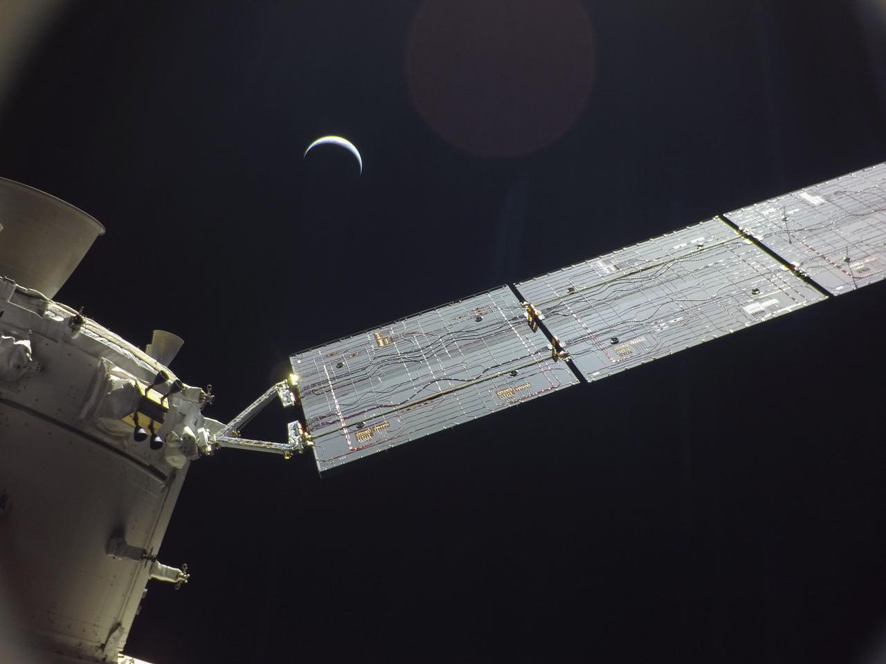
art001e001722 (Nov. 30, 2022) A camera mounted on the tip of one of Orion’s solar arrays captured the Earth as the spacecraft was in a distant lunar orbit.
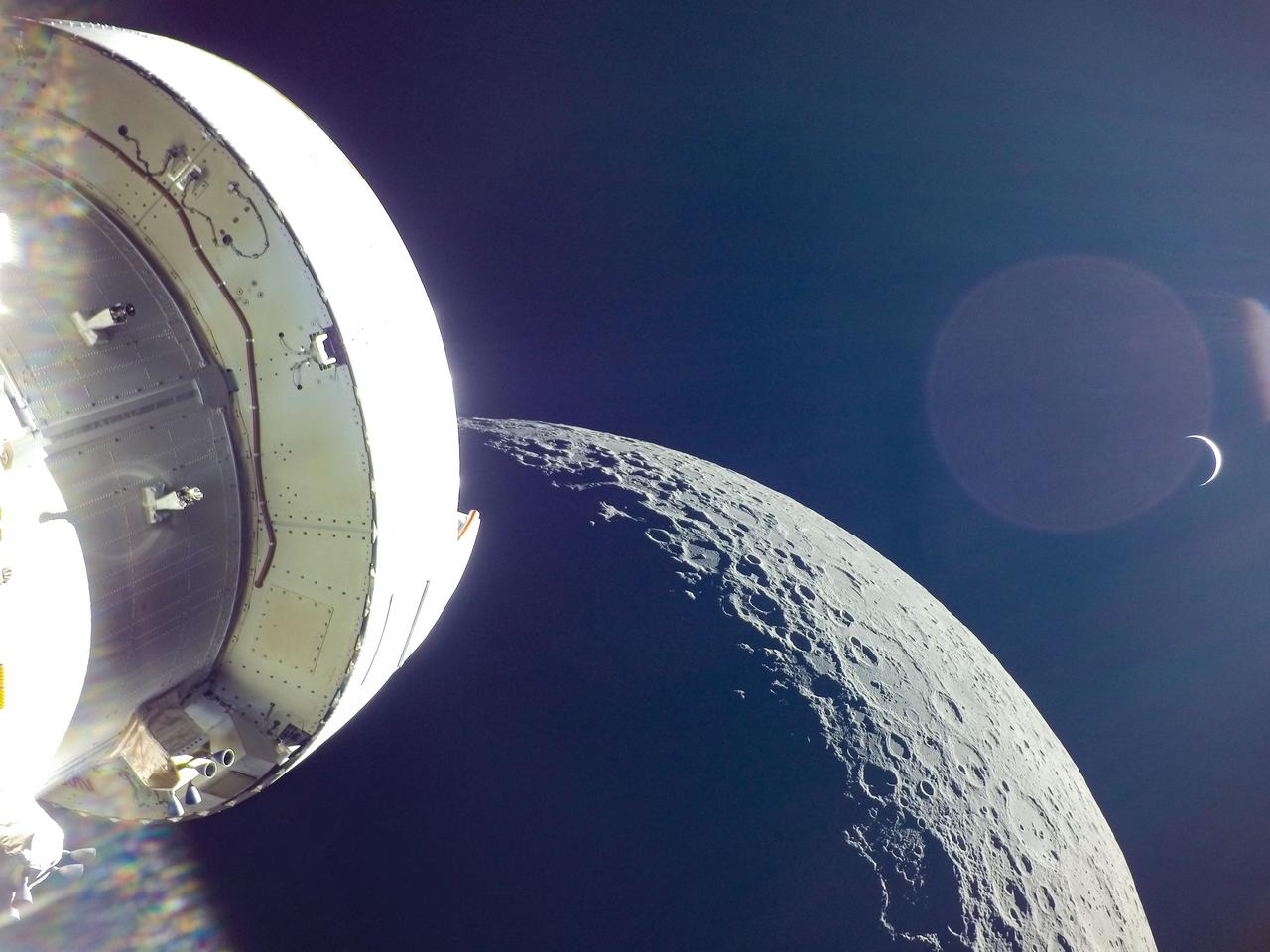
art0001e002092 (Dec. 5, 2022) On the 20th day of the Artemis I mission, Orion captured the Earth rising behind the Moon following the return powered flyby. The 3 minute, 27 second, return powered flyby burn, committed the spacecraft to a Dec. 11 splashdown in the Pacific Ocean.
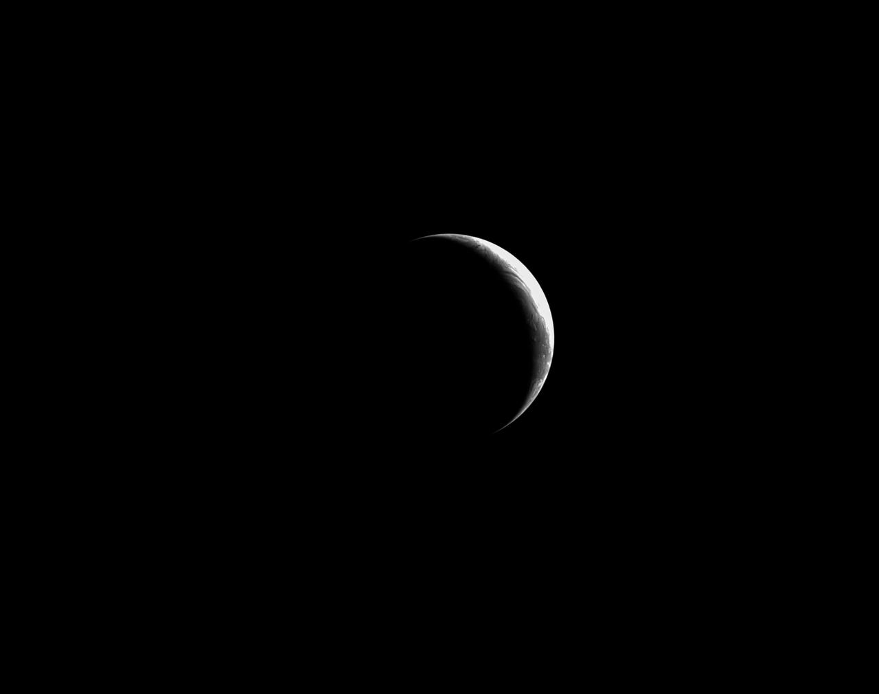
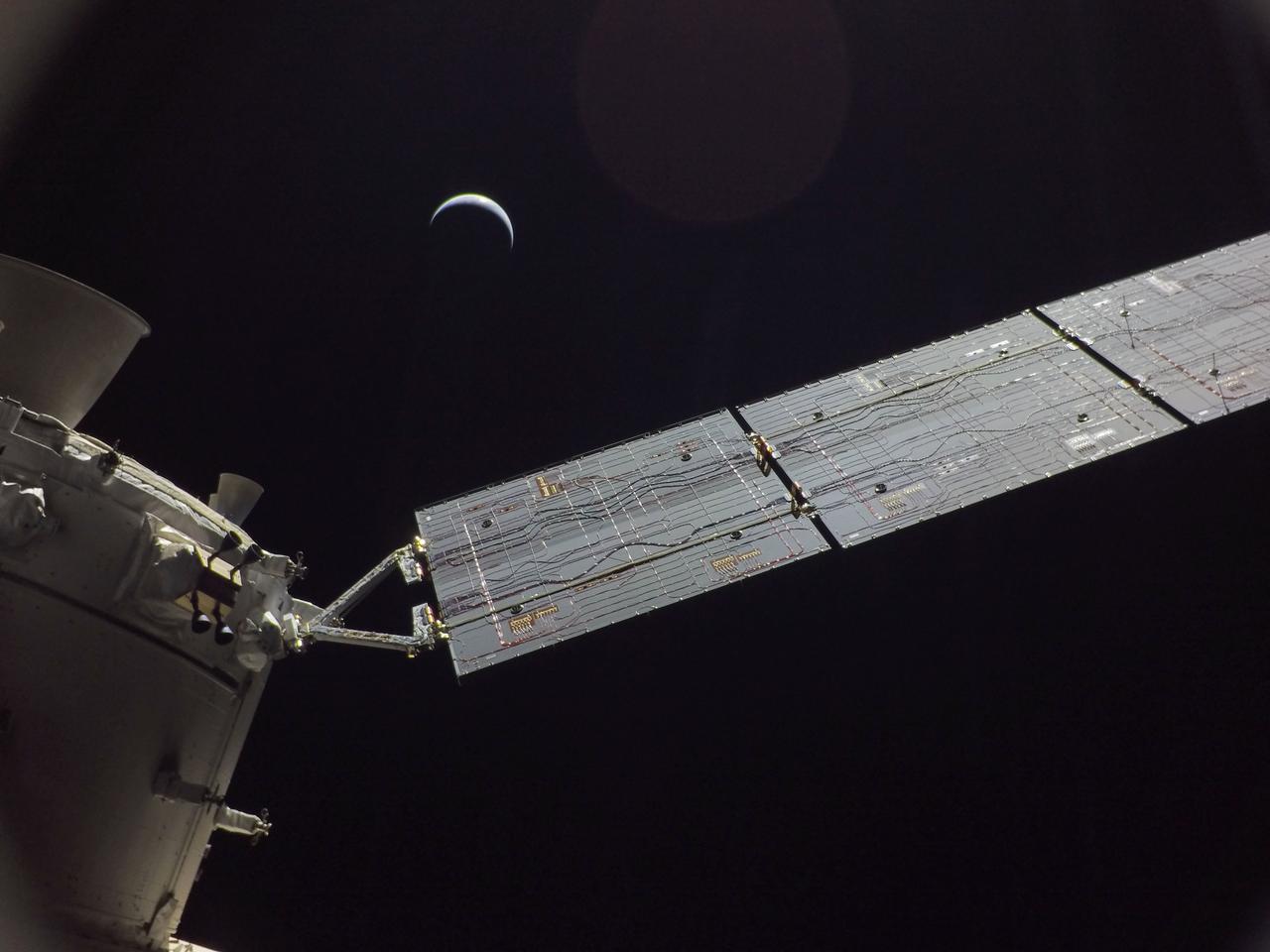
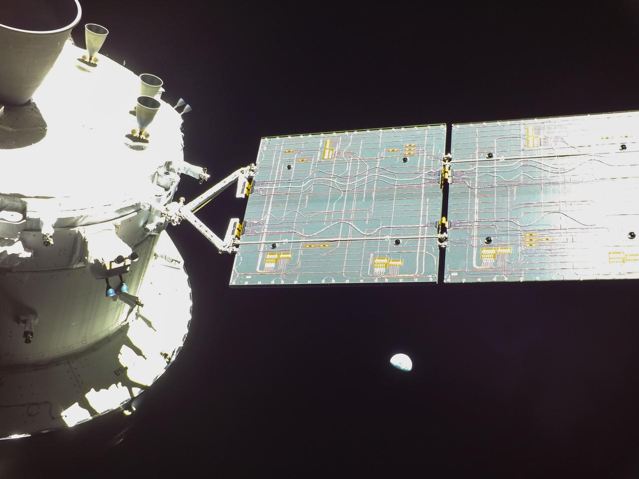
art001e002190 (Dec. 7, 2022) Orion continues its journey home to Earth, which appears here as a crescent, still 234,000 miles away. The Artemis I spacecraft is scheduled to splash down in the Pacific Ocean on Sunday, Dec. 11.
art001e003002 (Dec. 10, 2022) On flight day 25 of the Artemis I mission, Orion captured this photo of the Earth from a camera mounted on one of its solar arrays. The spacecraft is now closer to Earth than to the Moon, and will splash down on Sunday, Dec. 11.
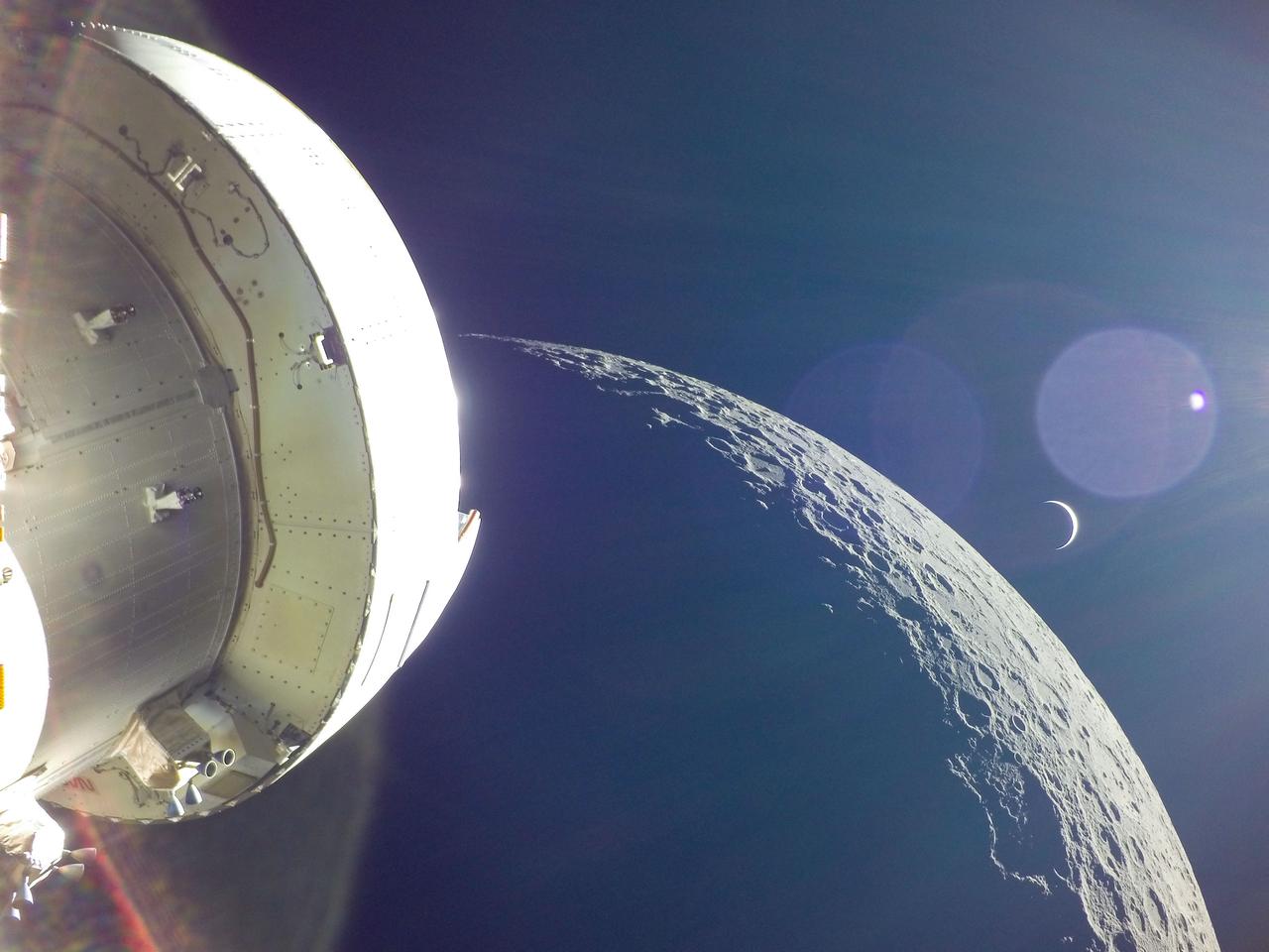
art0001e002083 (Dec. 5, 2022) On the 20th day of the Artemis I mission, Orion captured the Earth rising behind the Moon following the return powered flyby. The 3 minute, 27 second, return powered flyby burn, committed the spacecraft to a Dec. 11 splashdown in the Pacific Ocean.
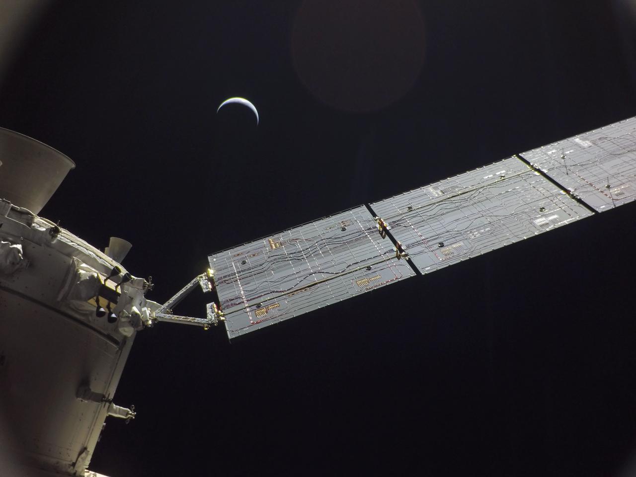
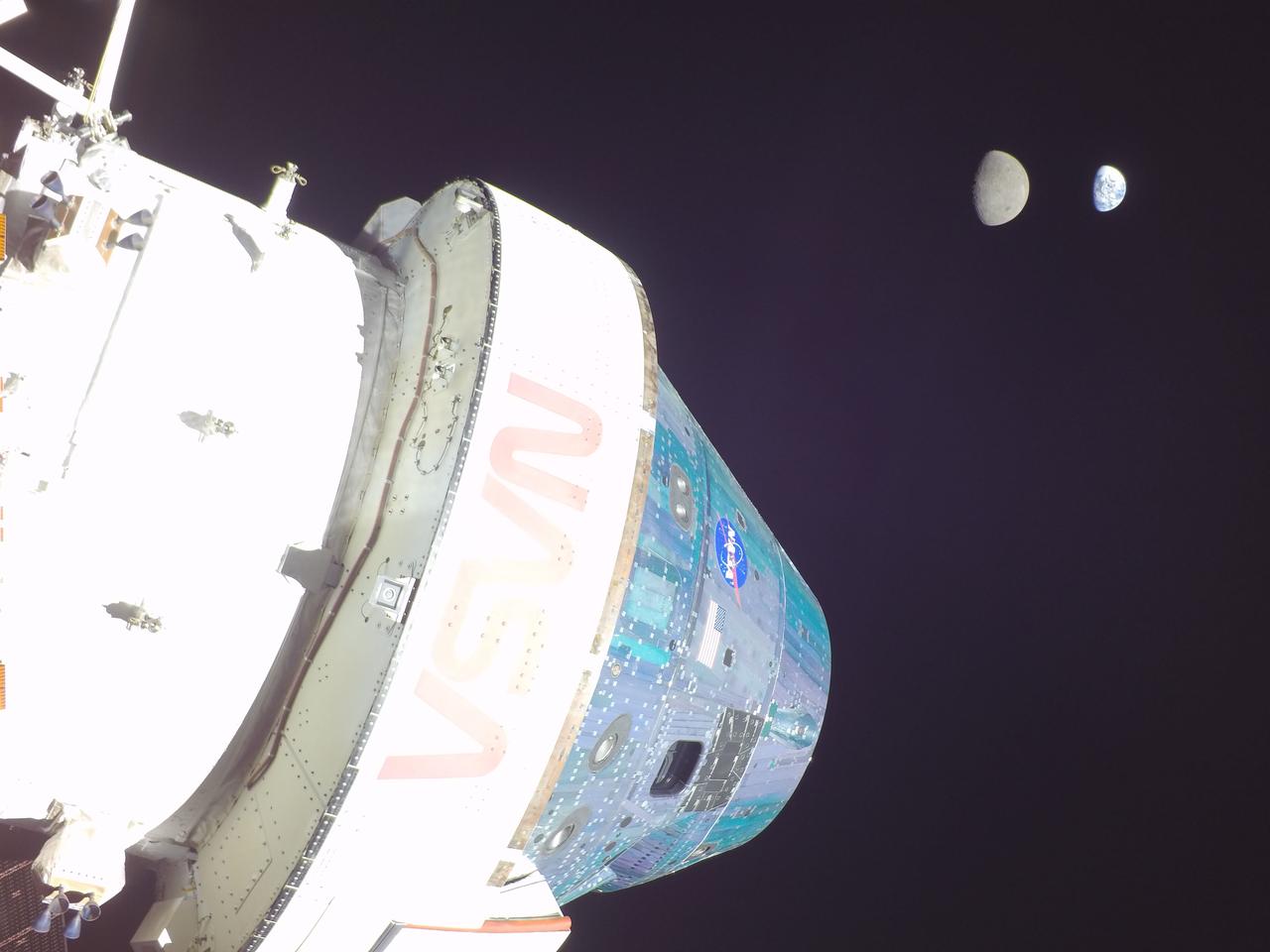
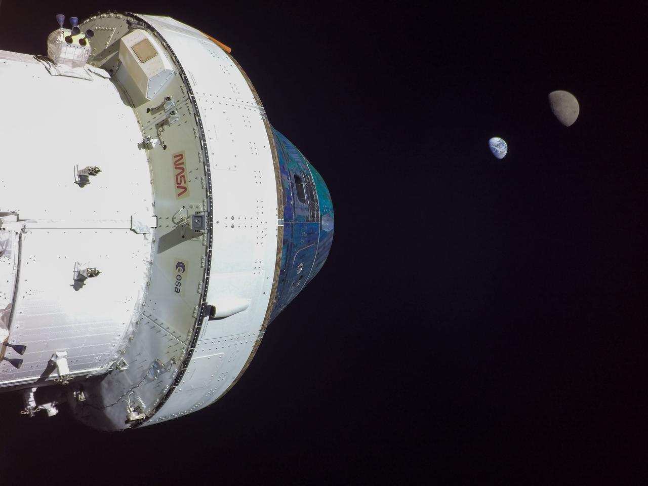
art001e001713 (Nov. 29, 2022) Orion’s solar arrays split the difference between Earth and the Moon on flight day 14 of the Artemis I mission in this image captured by a camera on the tip of one of the spacecraft’s four solar arrays.
art001e001712 (Nov. 29, 2022) Orion’s solar arrays split the difference between Earth and the Moon on flight day 14 of the Artemis I mission in this image captured by a camera on the tip of one of the spacecraft’s four solar arrays.
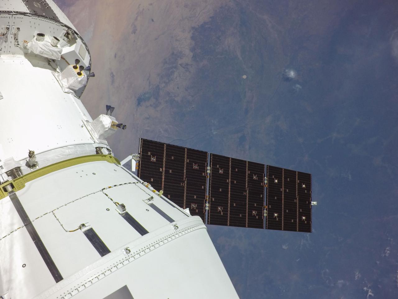
art001e000199 (Nov. 16, 2022) – One of Orion’s four solar arrays is seen during deployment shortly after the uncrewed Artemis I mission launched at 1:47 a.m. EST on Nov. 16, 2022, with the Earth still close below in the background.

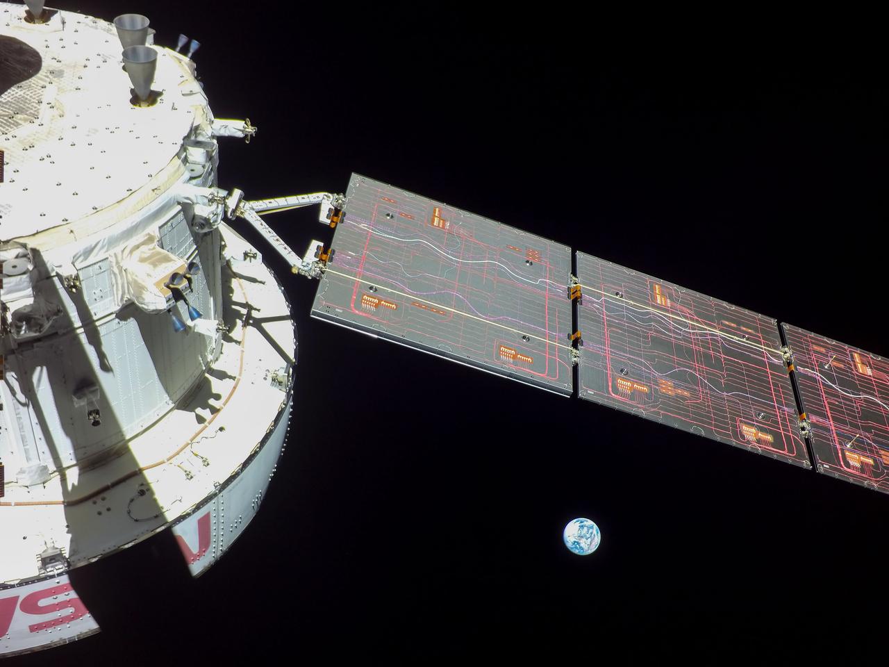
art001e000672 (Nov. 28, 2022) On flight day 13, Orion reached its maximum distance from Earth during the Artemis I mission when it was 268,563 miles away from our home planet. Orion has now traveled farther than any other spacecraft built for humans.
art001e002002 (Dec. 4, 2022) On the 19th day of the Artemis I mission, Orion captures Earth from a camera mounted on one of its solar arrays as the spacecraft prepares for the return powered flyby of the Moon on Dec. 5, when it will pass approximately 79 miles above the lunar surface.
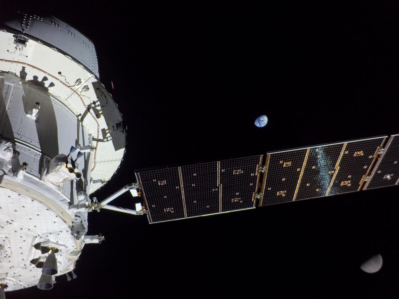
art001e000475 (Nov. 24, 2022) – On Flight Day 9, NASA’s Orion spacecraft captured imagery looking back at the Earth from a camera mounted on one of its solar arrays. The spacecraft is enroute to distant retrograde orbit of the Moon.
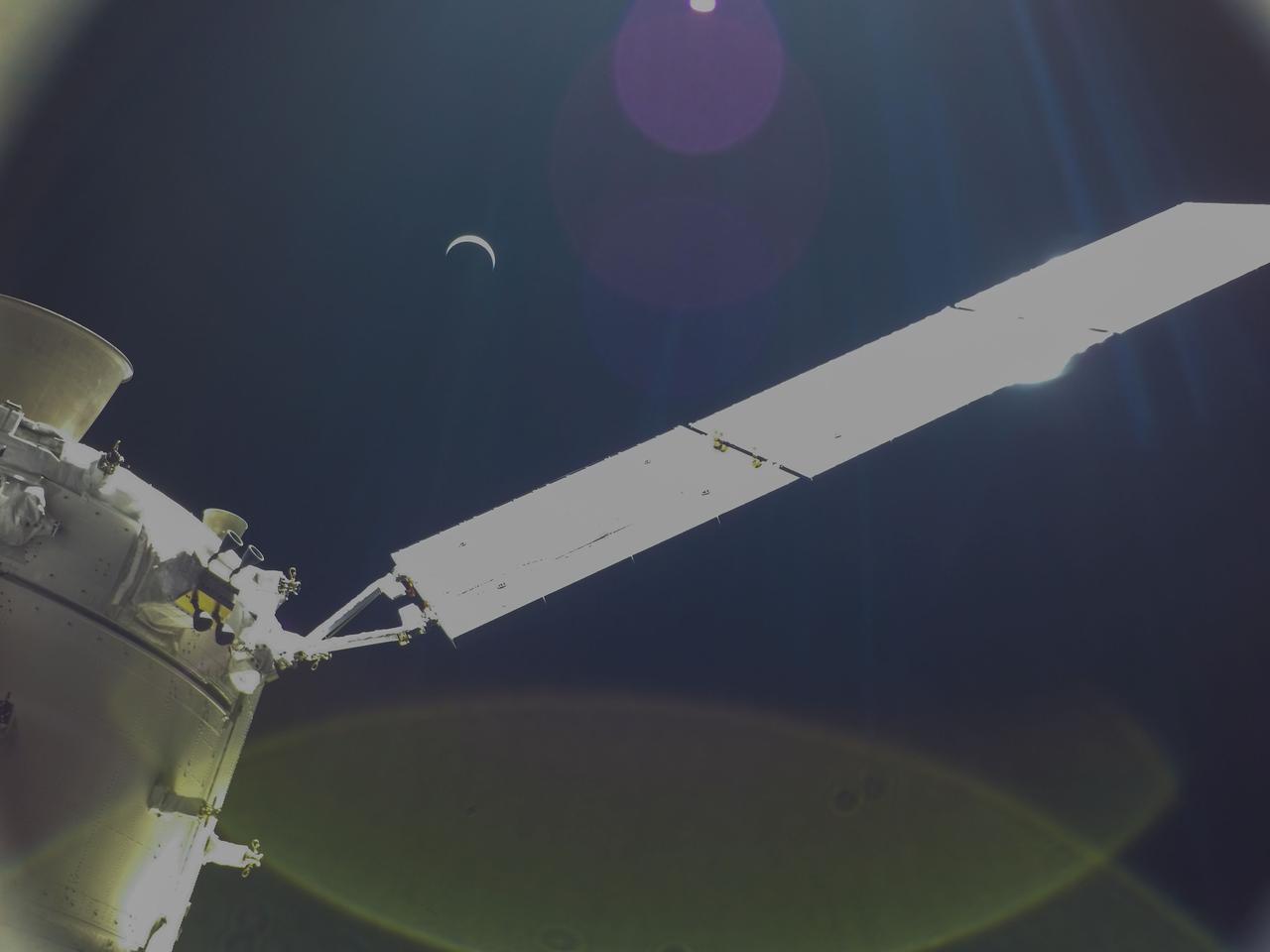
art001e002192 (Dec. 7, 2022) Orion continues its journey home to Earth, which appears here as a crescent, still 234,000 miles away. The Artemis I spacecraft is scheduled to splash down in the Pacific Ocean on Sunday, Dec. 11.
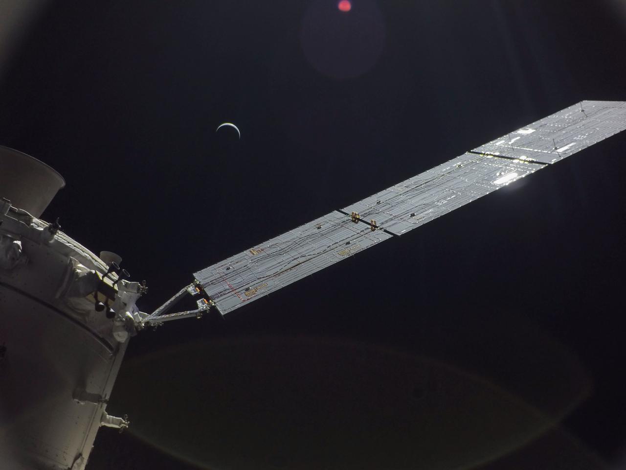
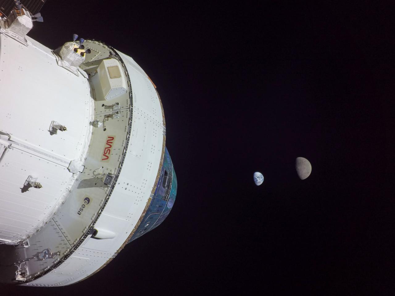
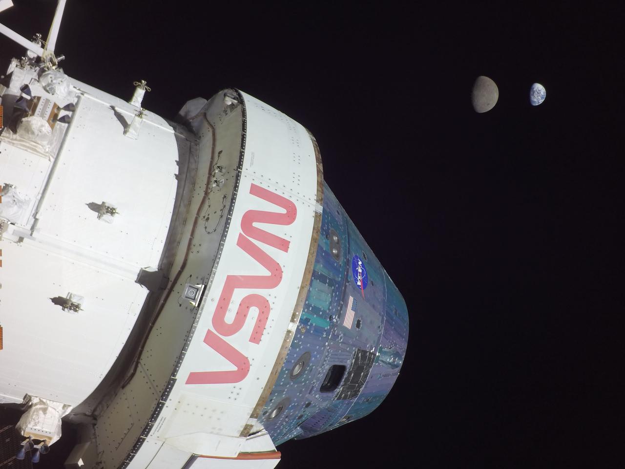
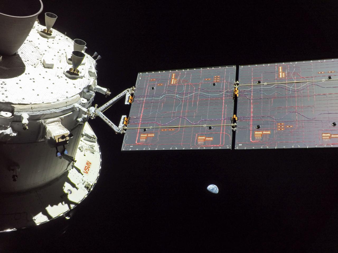
art001e001823 (Nov. 28, 2022) On flight day 13 of the Artemis I mission, Orion captured this view of Earth and the Moon on either sides of one of the spacecraft’s four solar arrays.
art001e002001 (Dec. 4, 2022) On the 19th day of the Artemis I mission, Orion captures Earth from a camera mounted on one of its solar arrays as the spacecraft prepares for the return powered flyby of the Moon on Dec. 5, when it will pass approximately 79 miles above the lunar surface.
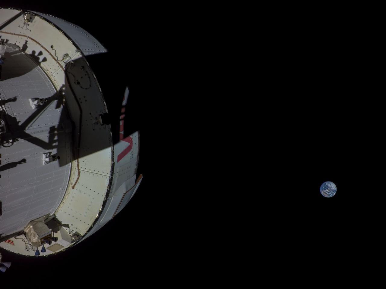
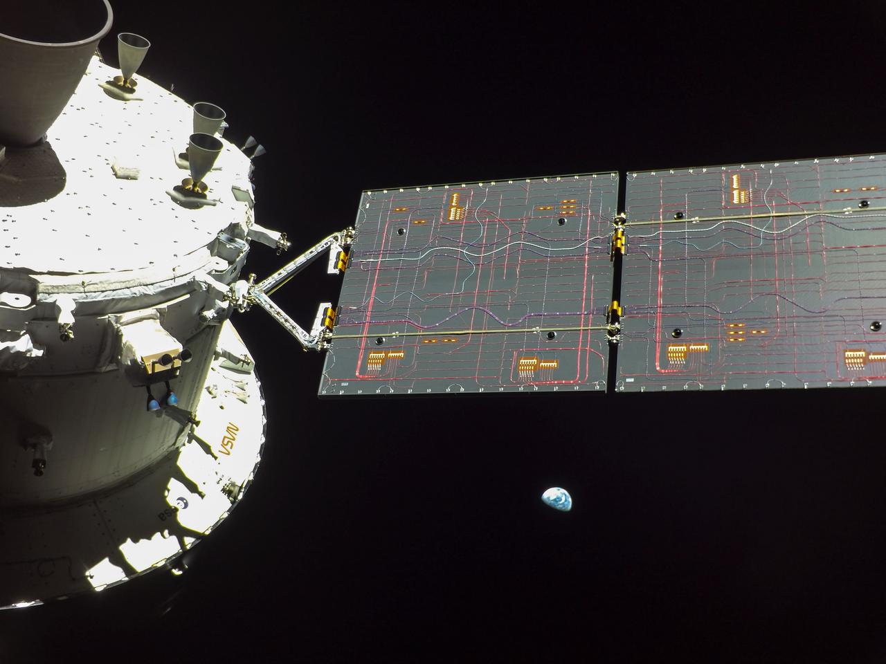
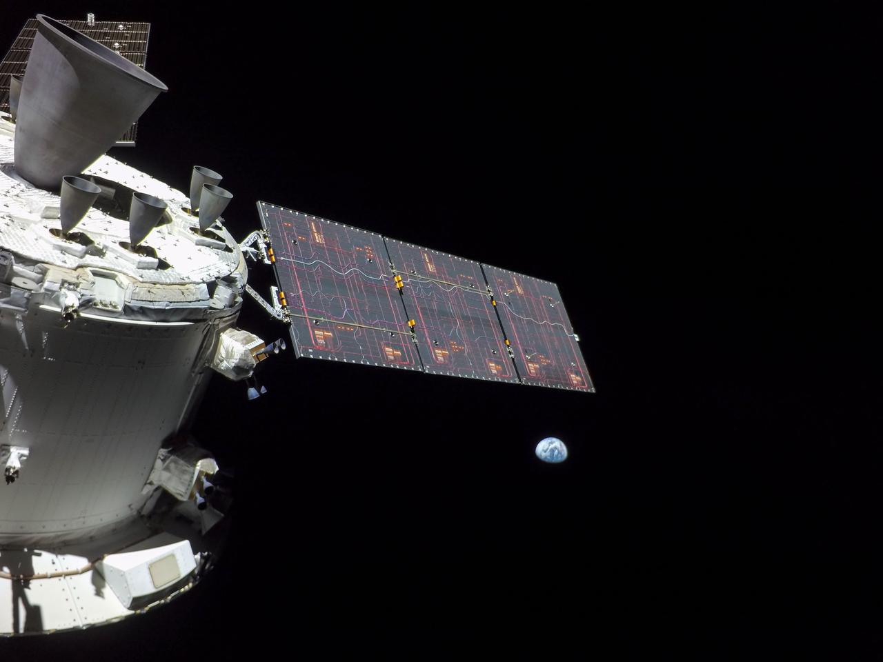
art001e000675 (Nov. 28, 2022) On flight day 13, Orion reached its maximum distance from Earth during the Artemis I mission when it was 268,563 miles away from our home planet. Orion has now traveled farther than any other spacecraft built for humans. The ESA (European Space Agency) logo can be seen in these photos on the European Service Module. This is ESA’s contribution to Orion and includes the large main engine on Orion, the Orbital Maneuvering System engine.

art001e001822 (Nov. 28, 2022) On flight day 13 of the Artemis I mission, Orion captured this view of Earth and the Moon on either sides of one of the spacecraft’s four solar arrays.
art001e000673 (Nov. 28, 2022) On flight day 13, Orion reached its maximum distance from Earth during the Artemis I mission when it was 268,563 miles away from our home planet. Orion has now traveled farther than any other spacecraft built for humans.
art001e003069 (Dec. 11, 2022) On the day of its return to Earth, Orion’s optical navigation camera captured this image of the planet. The spacecraft splashed down at 12:40 p.m. EST Dec. 11, completing the Artemis I mission and paving the way for future Artemis missions to land the first woman and first person of color on the Moon.
art001e000674 (Nov. 28, 2022) On flight day 13, Orion reached its maximum distance from Earth during the Artemis I mission when it was 268,563 miles away from our home planet. Orion has now traveled farther than any other spacecraft built for humans.
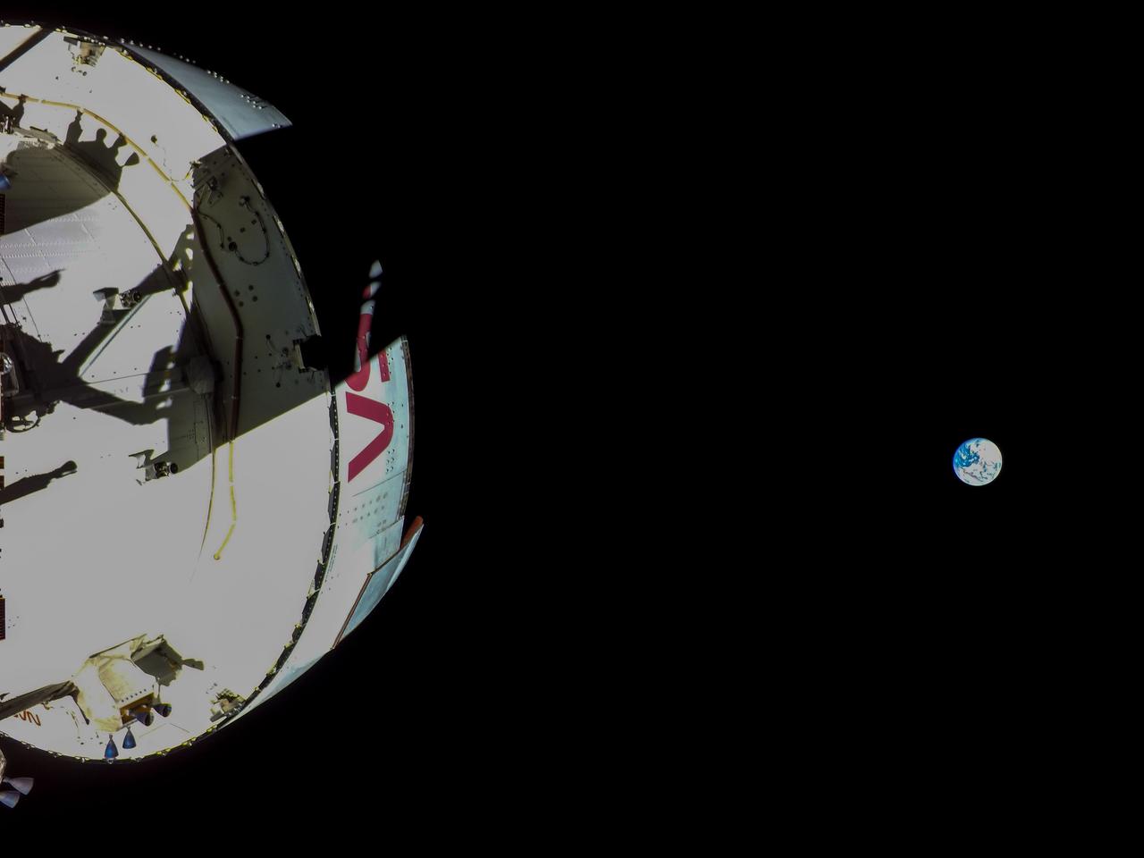
art001e000414 (Nov. 23, 2022) – On Flight Day 8, NASA’s Orion spacecraft remains two days away from reaching its distant retrograde orbit. The Earth is in view as Orion snaps a selfie using a camera mounted on one of its solar array at 10:56 p.m. EST.
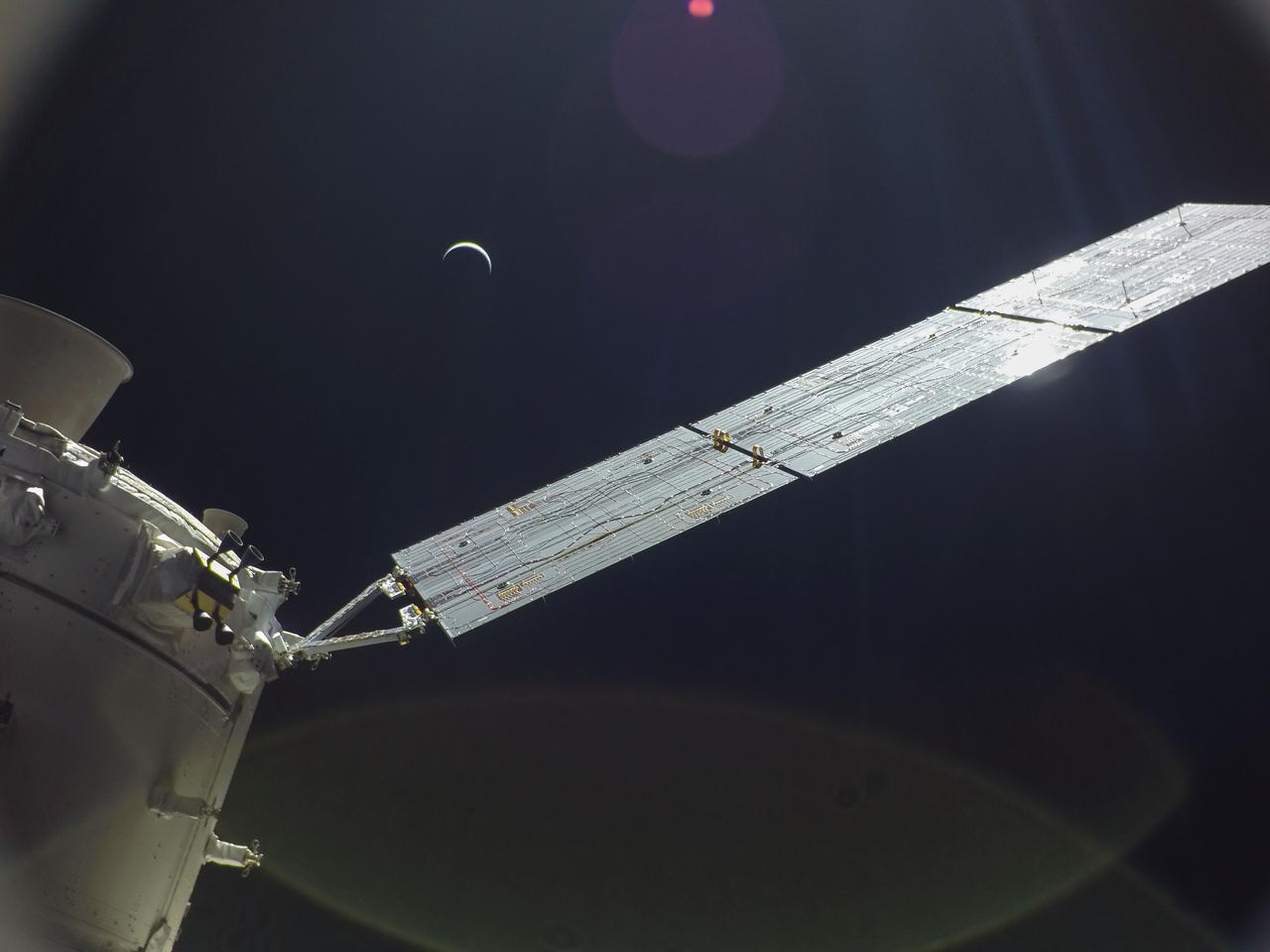
art001e002191 (Dec. 7, 2022) Orion continues its journey home to Earth, which appears here as a crescent, still 234,000 miles away. The Artemis I spacecraft is scheduled to splash down in the Pacific Ocean on Sunday, Dec. 11.
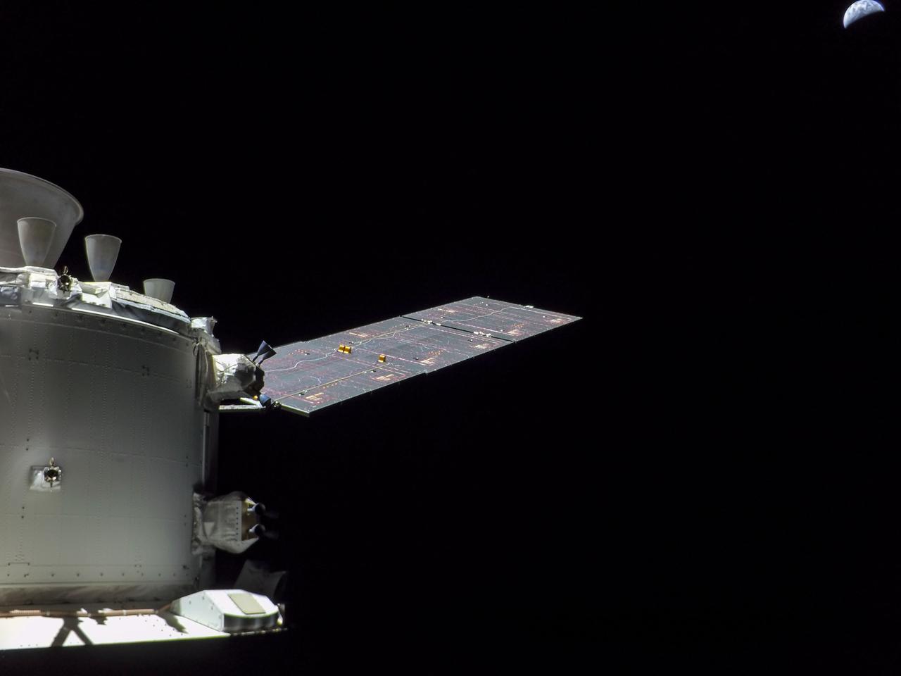
art001e001936 (Dec. 2, 2022) A camera mounted on one of Orion’s four solar arrays captured this image of the Earth on flight day 17 of the 25.5-day Artemis I mission from a distance of more than 222,000 miles. Orion has exited the distant lunar orbit and is heading for a Dec. 11 splashdown in the Pacific Ocean.
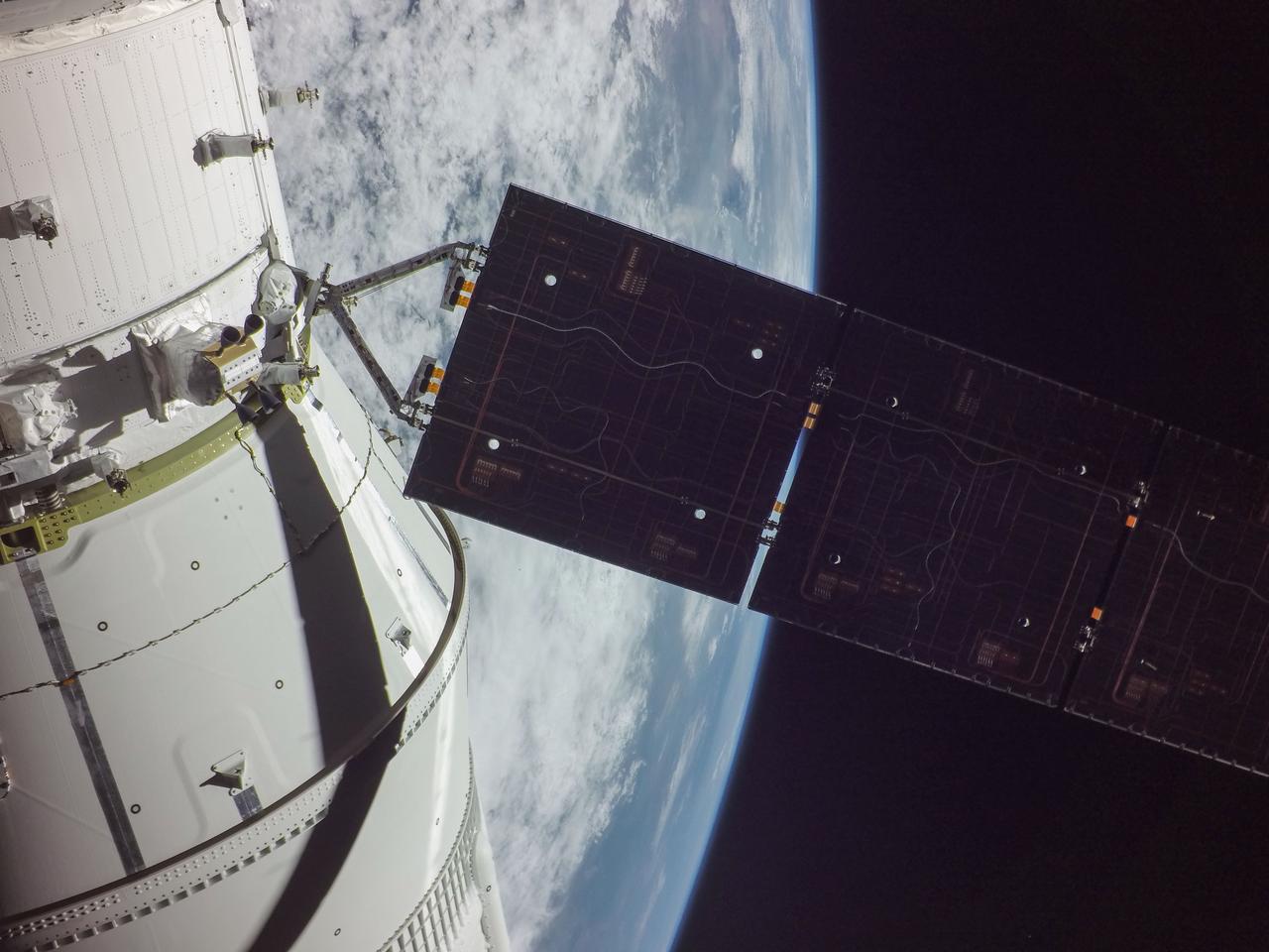
art001e000198 (Nov. 16, 2022) – One of Orion’s four solar arrays is seen during deployment shortly after the uncrewed Artemis I mission launched at 1:47 a.m. EST on Nov. 16, 2022.
art001e001721 (Nov. 30, 2022) A camera mounted on the tip of one of Orion’s solar arrays captured the Earth as the spacecraft was in a distant lunar orbit.
art001e000473 (Nov. 24, 2022) – On Flight Day 9, NASA’s Orion spacecraft captured imagery looking back at the Earth from a camera mounted on one of its solar arrays. The spacecraft is enroute to distant retrograde orbit of the Moon.
art001e001715 (Nov. 29, 2022) A camera on the tip of one of the Orion’s four solar arrays captured Earth when the spacecraft was 264,000 miles from our home planet on the Artemis I mission.
art001e003070 (Dec. 11, 2022) On the day of its return to Earth, Orion’s optical navigation camera captured this image of the planet. The spacecraft splashed down at 12:40 p.m. EST Dec. 11, completing the Artemis I mission and paving the way for future Artemis missions to land the first woman and first person of color on the Moon.
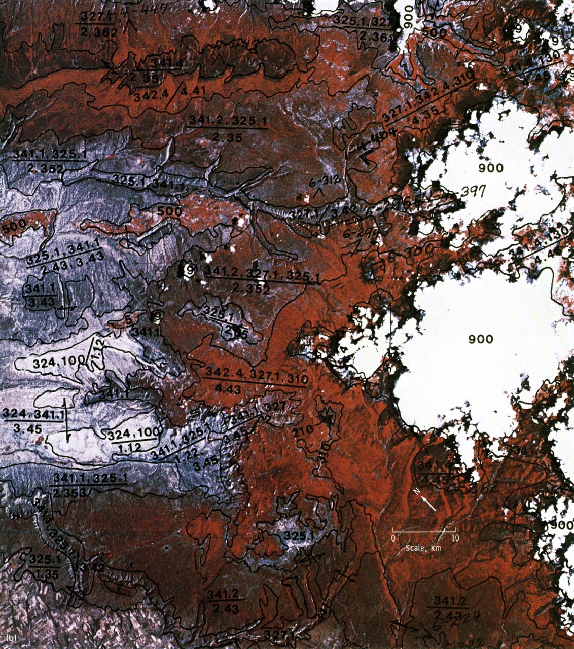
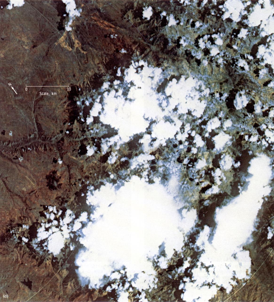
This EREP photograph of the Uncompahgre Plateau area of Colorado illustrates the land use classification using the hierarchical numbering system to depict land forms and vegetative patterns. The numerator is a three-digit number with decimal components identifying the vegetation analog or land use conditions. The denominator uses a three-component decimal system for landscape characterization.

This first high-resolution image, taken on the first day of the Artemis I mission, was captured by a camera on the tip of one of Orion’s solar arrays. The spacecraft was 57,000 miles from Earth when the image was captured, and continues to distance itself from planet Earth as it approaches the Moon and distant retrograde orbit.
art001e001716 (Nov. 29, 2022) A camera on the tip of one of the Orion’s four solar arrays captured Earth when the spacecraft was 264,000 miles from our home planet on the Artemis I mission.
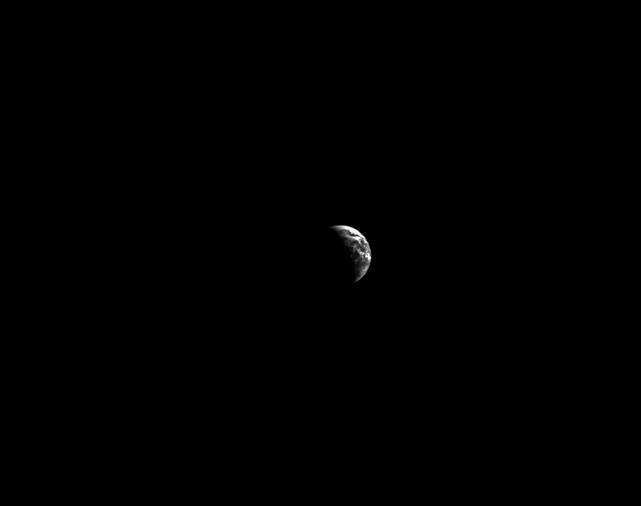
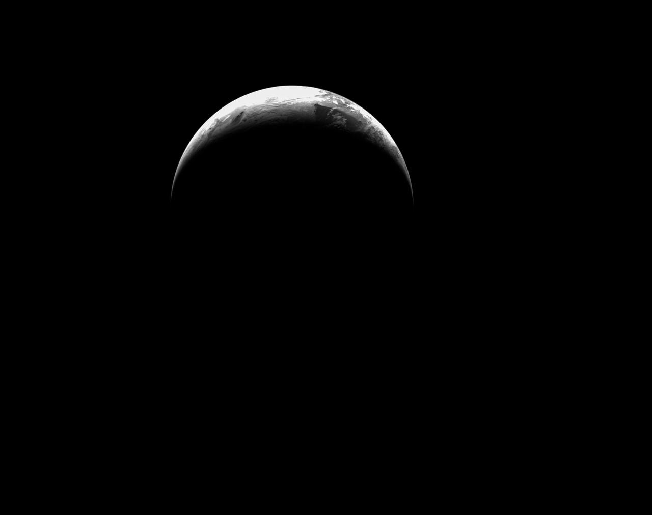
art001e001924 (Dec. 2, 2022) On flight day 17 of the Artemis I mission, Orion’s optical navigation camera captured this black-and-white image of our Earth as the spacecraft sets its sights on a Dec. 11 splashdown in the Pacific Ocean. Orion uses the optical navigation camera to capture imagery of the Earth and the Moon at different phases and distances, providing an enhanced body of data to certify its effectiveness under different lighting conditions as a way to help orient the spacecraft on future missions with crew.
art001e003001 (Dec. 10, 2022) On flight day 25 of the Artemis I mission, Orion captured this photo of the Earth from a camera mounted on one of its solar arrays. The spacecraft is now closer to Earth than to the Moon, and will splash down on Sunday, Dec. 11.
art001e000472 (Nov. 24, 2022) – On Flight Day 9, NASA’s Orion spacecraft captured imagery looking back at the Earth from a camera mounted on one of its solar arrays. The spacecraft is enroute to distant retrograde orbit of the Moon.
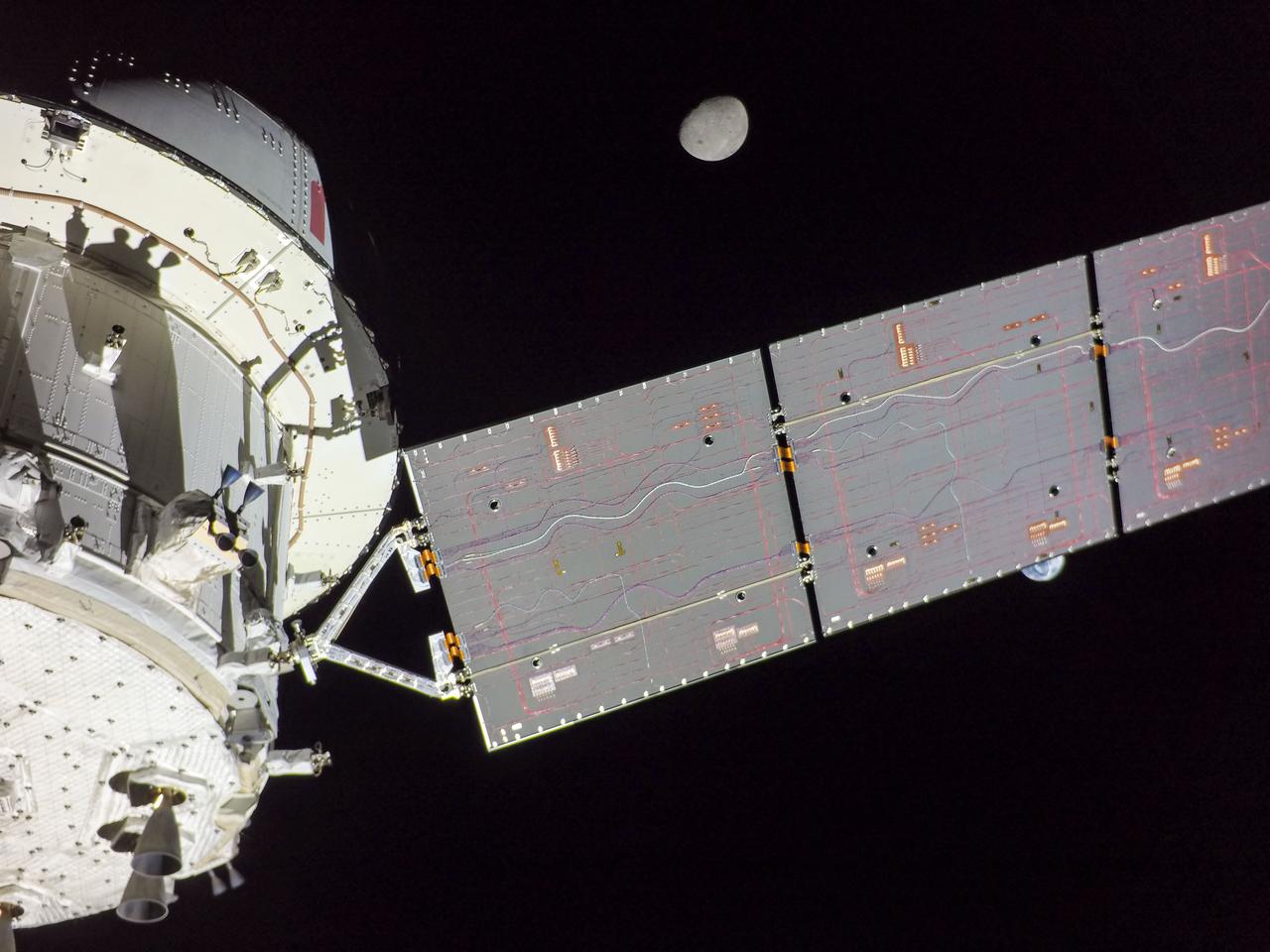
art001e000666 (Nov. 27, 2022) On flight day 12 of the 25.5-day Artemis I mission, a camera on the tip of one of Orion’s solar arrays captured the Earth as Orion travels in distant retrograde orbit around the Moon.

art001e001714 (Nov. 29, 2022) Orion’s solar arrays split the difference between Earth and the Moon on flight day 14 of the Artemis I mission in this image captured by a camera on the tip of one of the spacecraft’s four solar arrays.
art001e000476 (Nov. 24, 2022) – On Flight Day 9, NASA’s Orion spacecraft captured imagery looking back at the Earth from a camera mounted on one of its solar arrays. The spacecraft is enroute to distant retrograde orbit of the Moon.
art001e001717 (Nov. 29, 2022) A camera on the tip of one of the Orion’s four solar arrays captured Earth when the spacecraft was 264,000 miles from our home planet on the Artemis I mission.
art001e002003 (Dec. 4, 2022) On the 19th day of the Artemis I mission, Orion captures Earth from a camera mounted on one of its solar arrays as the spacecraft prepares for the return powered flyby of the Moon on Dec. 5, when it will pass approximately 79 miles above the lunar surface.
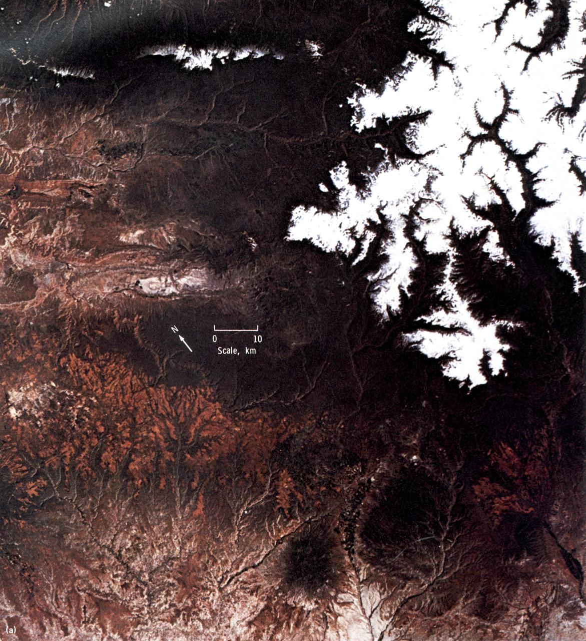
This EREP color photograph of the Uncompahgre Plateau area of Colorado was taken in June of 1973 by the Skylab Multi-spectral Photographic Camera (Skylab EREP Experiment S190A) of the Multi-spectral Photographic Facility during the Skylab-2 Mission.
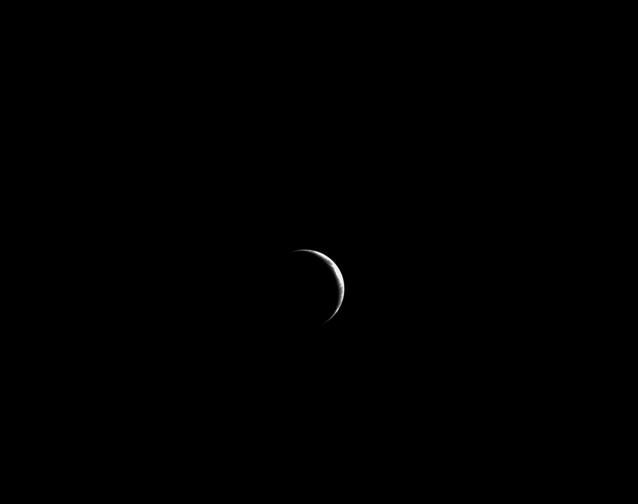
art001e002518 (Dec. 9, 2022) On flight day 24 of the Artemis I mission, Orion’s optical navigation camera captured this black-and-white photo of Earth as a sliver. Orion uses the optical navigation camera to capture imagery of the Earth and the Moon at different phases and distances, providing an enhanced body of data to certify its effectiveness under different lighting conditions as a way to help orient the spacecraft on future missions with crew.
art001e003003 (Dec. 10, 2022) On flight day 25 of the Artemis I mission, Orion captured this photo of the Earth from a camera mounted on one of its solar arrays. The spacecraft is now closer to Earth than to the Moon, and will splash down on Sunday, Dec. 11.
art001e000679 (Nov. 28, 2022) On flight day 13, Orion reached its maximum distance from Earth during the Artemis I mission when it was 268,563 miles away from our home planet. Orion has now traveled farther than any other spacecraft built for humans. The ESA (European Space Agency) logo can be seen in these photos on the European Service Module. This is ESA’s contribution to Orion and includes the large main engine on Orion, the Orbital Maneuvering System engine.

SL3-22-0214 (July-September 1973) --- A vertical view of southeastern Washington State as photographed from Earth orbit by one of the six lenses of the Itek-furnished S190-A Multispectral Photographic Facility Experiment aboard the Skylab space station. The Snake River flows into the Columbia River in the most southerly corner of the picture. The Wallula Lake is below the junction of the two rivers. The Yakima Valley is at the southwestern edge of the photograph. The Columbia Basin is in the center of the picture. The Cascade Range extends across the northwest corner of the photograph. This picture was taken with type SO-356 regular color film. The S190-A experiment is part of the Earth Resources Experiments Package. Federal agencies participating with NASA on the EREP project are the Departments of Agriculture, Commerce, Interior, the Environmental Protection Agency and the Corps of Engineers. All EREP photography is available to the public through the Department of Interior?s Earth Resources Observations Systems Data Center, Sioux Falls, South Dakota, 57198. Photo credit: NASA

SL3-40-077 (July-September 1973) --- A vertical view of the Mediterranean coastal area of southeastern France as photographed from Earth orbit by one of the six lenses of the Itek-furnished S190-A Multispectral Photographic Facility Experiment aboard the Skylab space station. This view of the coast extends from the eastern outskirts of Marseilles easterly to Cannes, and includes the city of Toulon. The S190-A experiment is part of the Skylab Earth Resources Experiments Package. Federal agencies participating with NASA on the EREP project are the Departments of Agriculture, Commerce, Interior, the Environmental Protection Agency and the Corps of Engineers. All EREP photography is available to the public through the Department of Interior?s Earth Resources Observations Systems Data Center, Sioux Falls, South Dakota, 57198. Photo credit: NASA
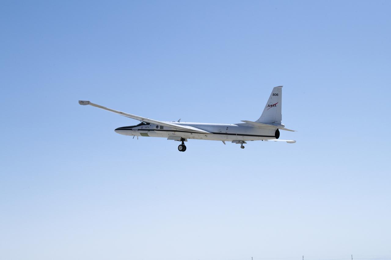
NASA’s ER-2 No. 806 returns to flying high-altitude on April 7, 2022, after three years of heavy maintenance. NASA Armstrong operates two ER-2 aircraft to collect information about Earth resources, celestial observations, atmospheric chemistry and dynamics, and oceanic processes.
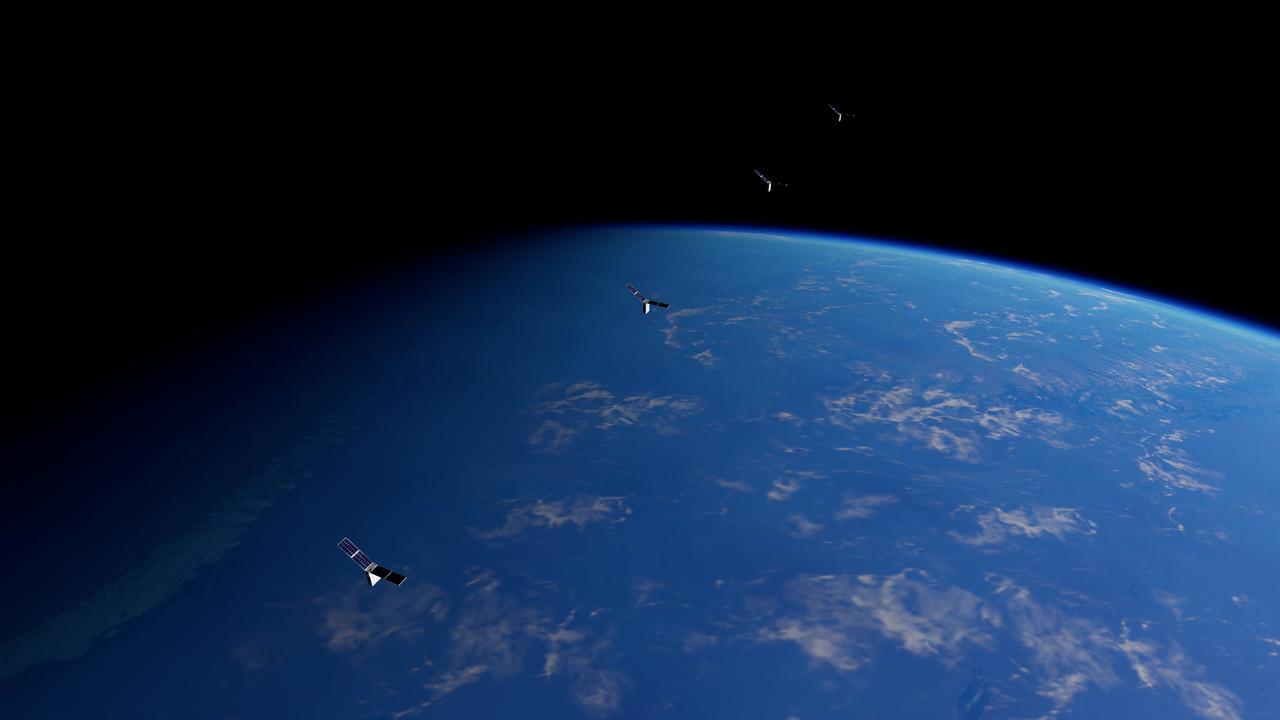
NASA’s Starling six-month mission will use a team of four CubeSats in low-Earth orbit to test technologies that let spacecraft operate in a synchronized manner without resources from the ground. The technologies will advance capabilities in swarm maneuver planning and execution, communications networking, relative navigation, and autonomous coordination between spacecraft.
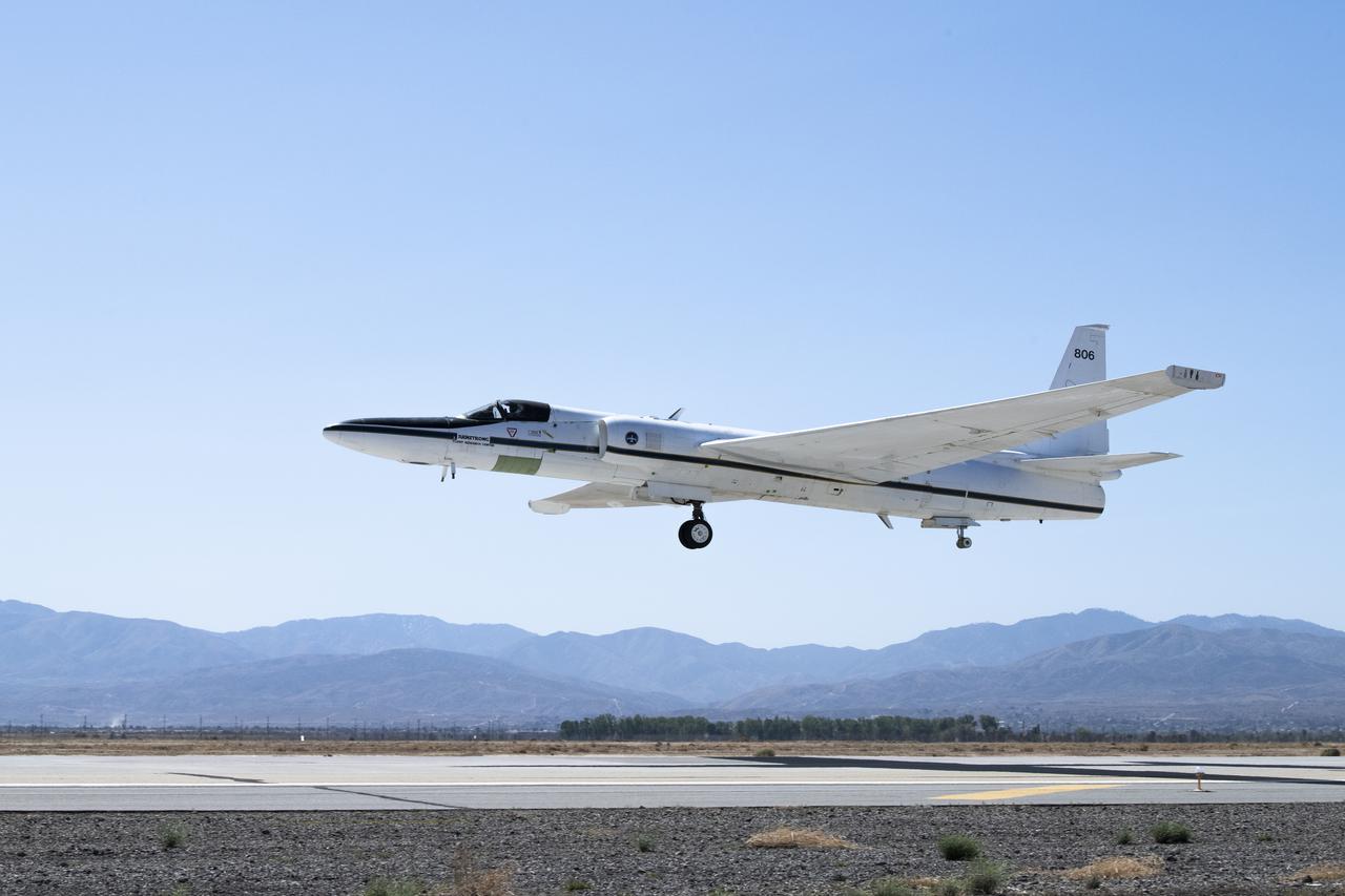
NASA's ER-2 No. 806 returns to flying high-altitude on April 7, 2022, after three years of heavy maintenance. NASA Armstrong operates two ER-2 aircraft to collect information about Earth resources, celestial observations, atmospheric chemistry and dynamics, and oceanic processes.
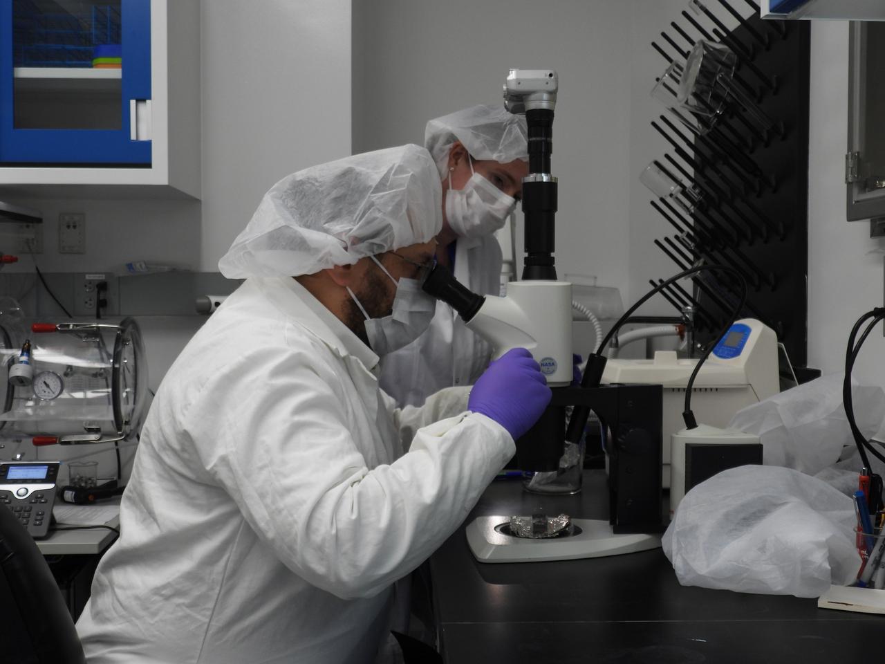
Jason Dworkin, project scientist for NASA's OSIRIS-REx (Origins, Spectral Interpretation, Resource Identification, and Security – Regolith Explorer) mission, examines a portion of the asteroid Bennu sample delivered to Earth in a laboratory at the agency's Goddard Space Flight Center in Greenbelt, Maryland.
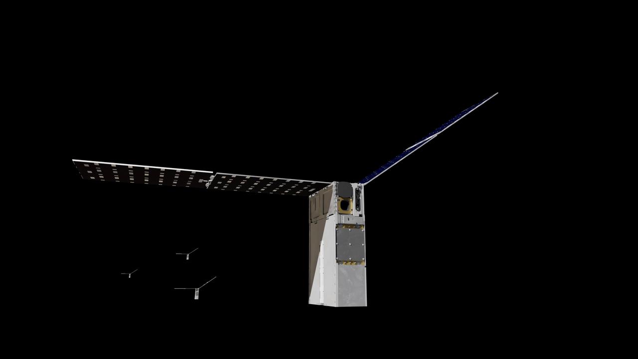
NASA’s Starling six-month mission will use a team of four CubeSats in low-Earth orbit to test technologies that let spacecraft operate in a synchronized manner without resources from the ground. The technologies will advance capabilities in swarm maneuver planning and execution, communications networking, relative navigation, and autonomous coordination between spacecraft.
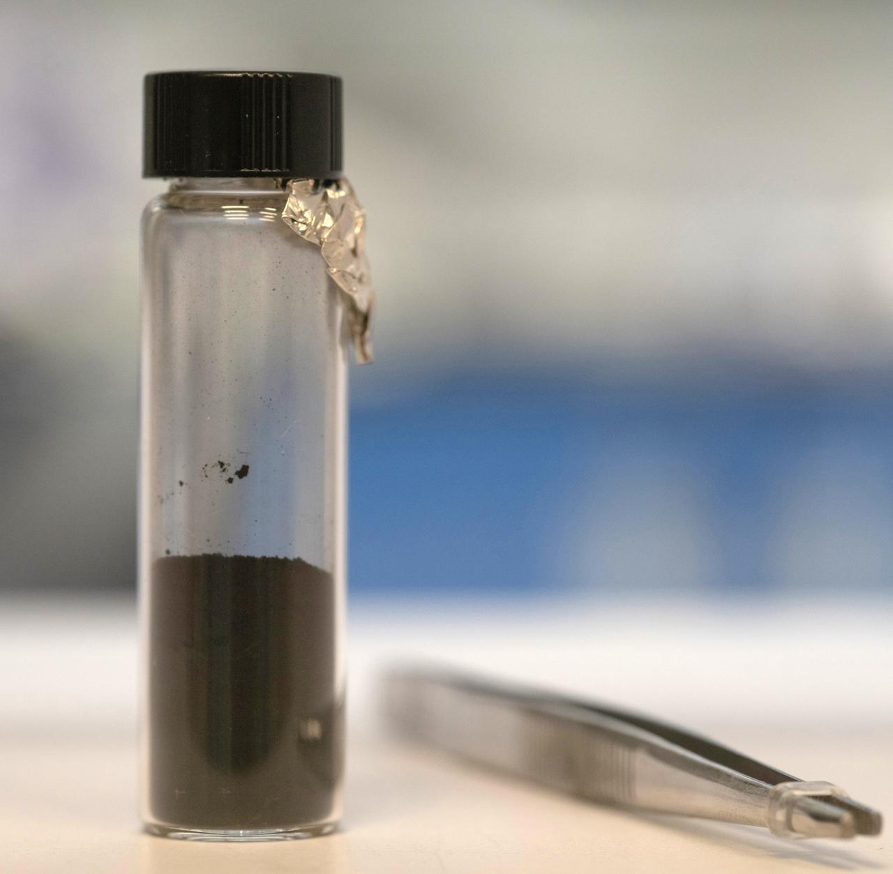
Photographed inside a laboratory at NASA's Goddard Space Flight Center in Greenbetl, Maryland, this vial contains a portion of the asteroid Bennu sample delivered to Earth by the agency's OSIRIS-REx (Origins, Spectral Interpretation, Resource Identification, and Security – Regolith Explorer) mission.
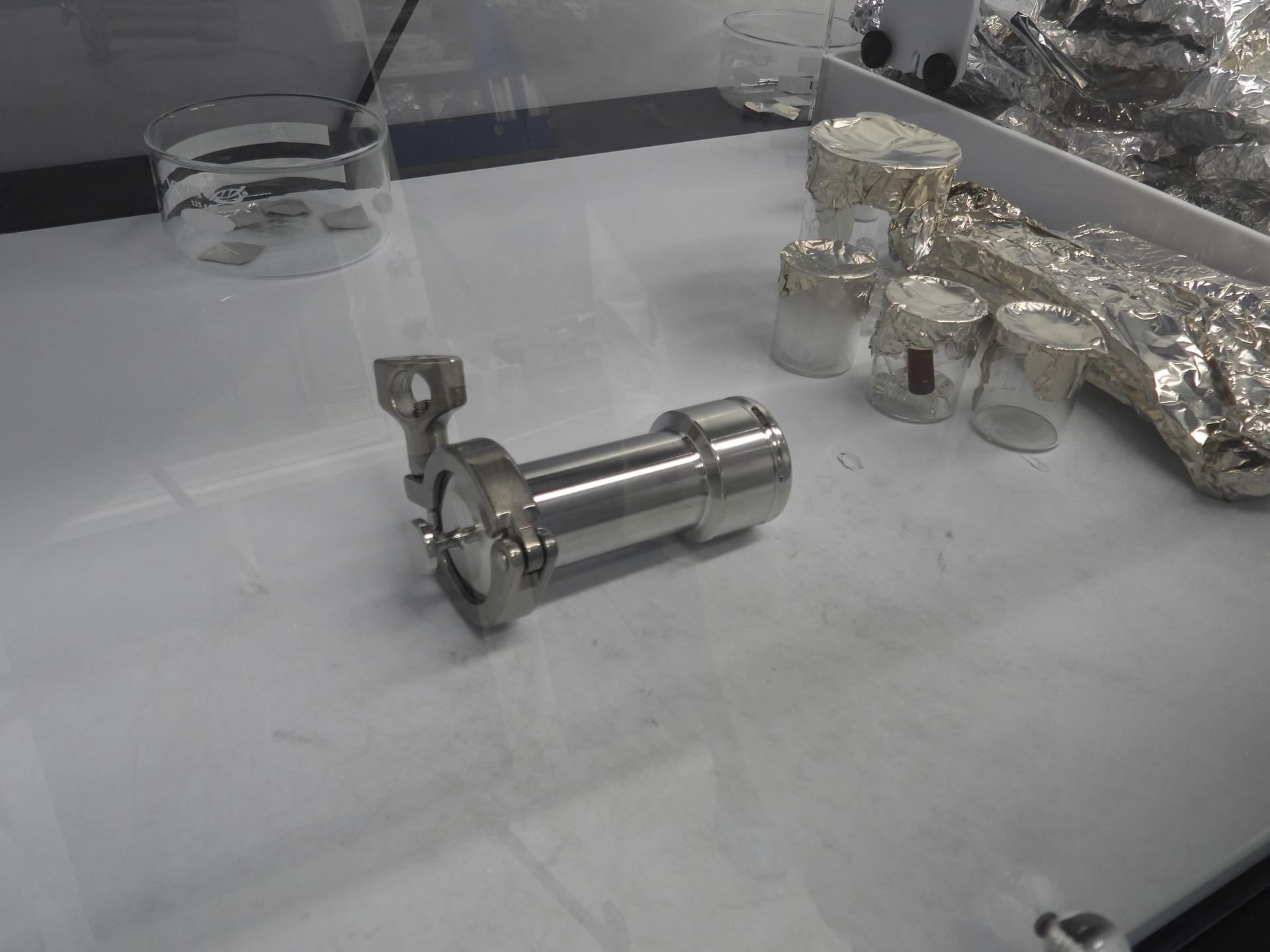
Photographed inside a laboratory at NASA's Goddard Space Flight Center in Greenbelt, Maryland, this cannister contains a portion of the asteroid Bennu sample delivered to Earth by the agency's OSIRIS-REx (Origins, Spectral Interpretation, Resource Identification, and Security – Regolith Explorer) mission.

In this video frame, Jason Dworkin holds up a vial that contains part of the sample from asteroid Bennu delivered to Earth by NASA's OSIRIS-REx (Origins, Spectral Interpretation, Resource Identification, and Security – Regolith Explorer) mission in 2023. Dworkin is the mission's project scientist at NASA's Goddard Space Flight Center in Greenbelt, Maryland.
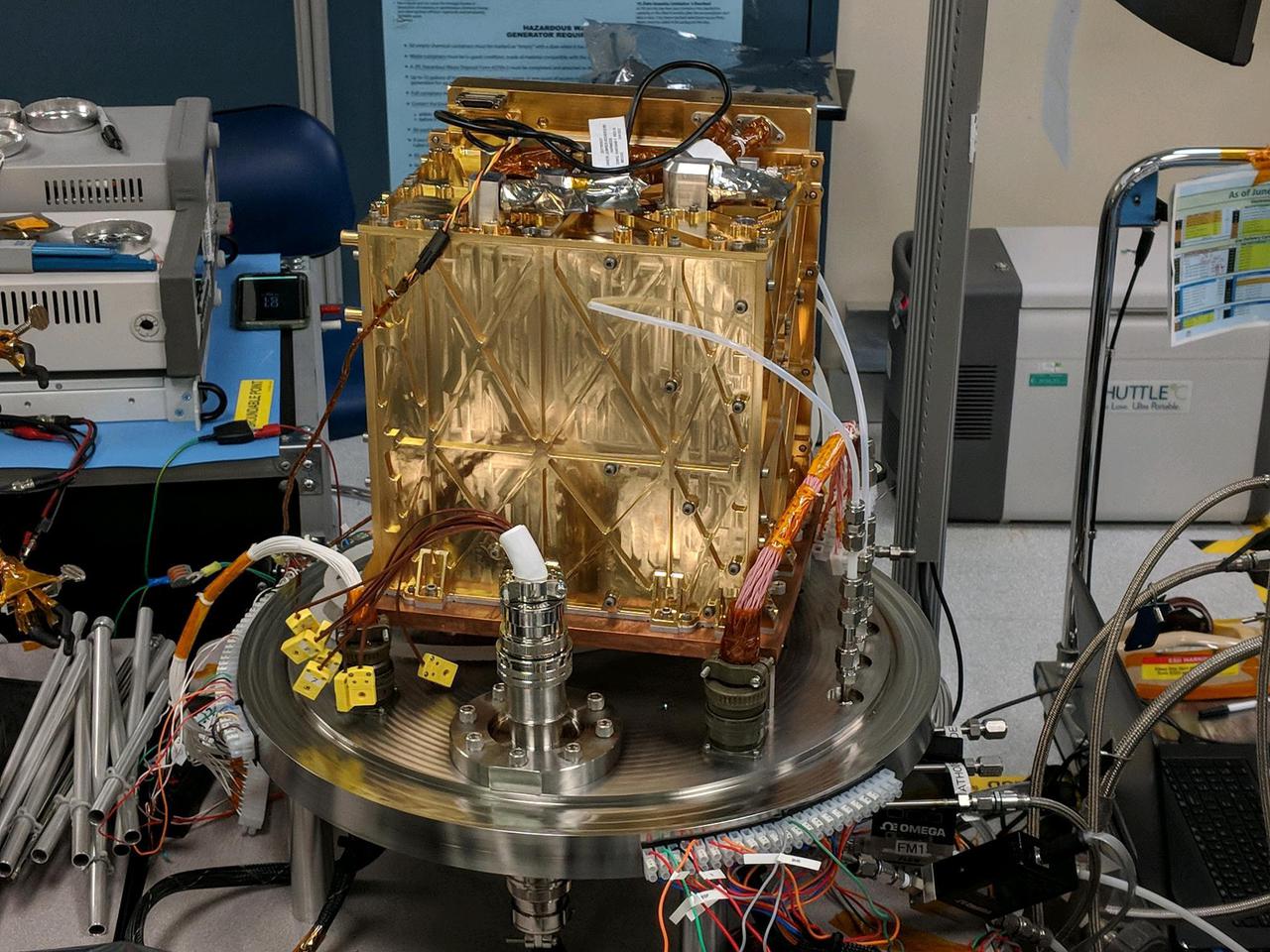
This engineering model of Mars Oxygen In-Situ Resource Utilization Experiment (MOXIE) instrument is about to undergo vibration testing in a lab at the Jet Propulsion Laboratory in Pasadena, California. Vibration tests demonstrate the ability of instruments to survive the extreme conditions of both a rocket launch from Earth and a landing on Mars. https://photojournal.jpl.nasa.gov/catalog/PIA24202

NASA’s Starling six-month mission will use a team of four CubeSats in low-Earth orbit to test technologies that let spacecraft operate in a synchronized manner without resources from the ground. The technologies will advance capabilities in swarm maneuver planning and execution, communications networking, relative navigation, and autonomous coordination between spacecraft.
/nasa-goddard-astrobio (2)~medium.jpg)
Researchers at NASA's Goddard Space Flight Center in Greenbelt, Maryland, who had a hand in studying the asteroid Bennu sample delivered to Earth by the agency's OSIRIS-REx (Origins, Spectral Interpretation, Resource Identification, and Security – Regolith Explorer) mission.
/nasa-goddard-astrobio (1)~medium.jpg)
Researchers at NASA's Goddard Space Flight Center in Greenbelt, Maryland, who had a hand in studying the asteroid Bennu sample delivered to Earth by the agency's OSIRIS-REx (Origins, Spectral Interpretation, Resource Identification, and Security – Regolith Explorer) mission.
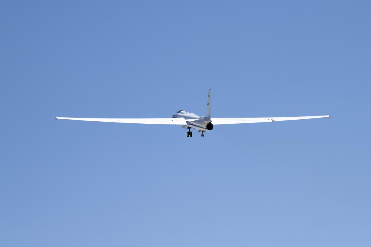
NASA’s ER-2 No. 806 returns to flying high-altitude on April 7, 2022, after three years of heavy maintenance. NASA Armstrong operates two ER-2 aircraft to collect information about Earth resources, celestial observations, atmospheric chemistry and dynamics, and oceanic processes.
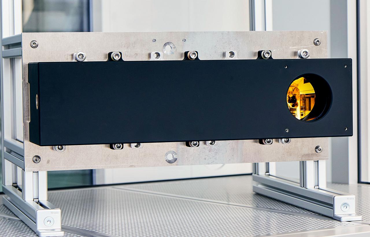
jsc2021e064350 (10/28/2021) --- Preflight image showing LisR on the assembly support structure in the clean room of Fraunhofer EMI. Longwave Infrared Sensing demonstratoR (Nanoracks-LisR) takes precise measurements of Earth's surface temperature as a way to monitor water resources. Copyright by Fraunhofer EMI.
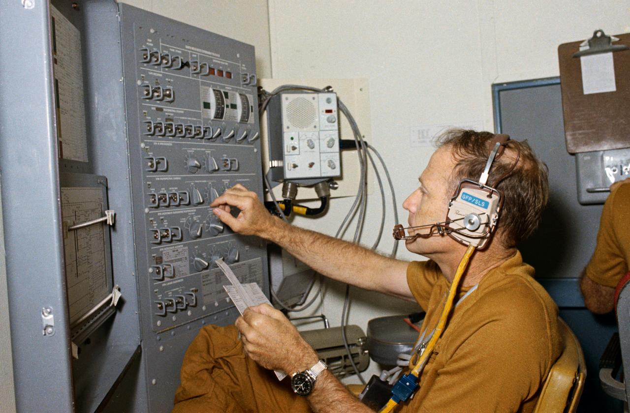
S73-32847 (10 Sept. 1973) --- Astronaut Gerald P. Carr, Skylab 4 commander, changes a dial on the control and display panel for the Earth Resources Experiments package (EREP) during a training exercise in the Multiple Docking Adapter (MDA) one-G trainer at Johnson Space Center. Photo credit: NASA
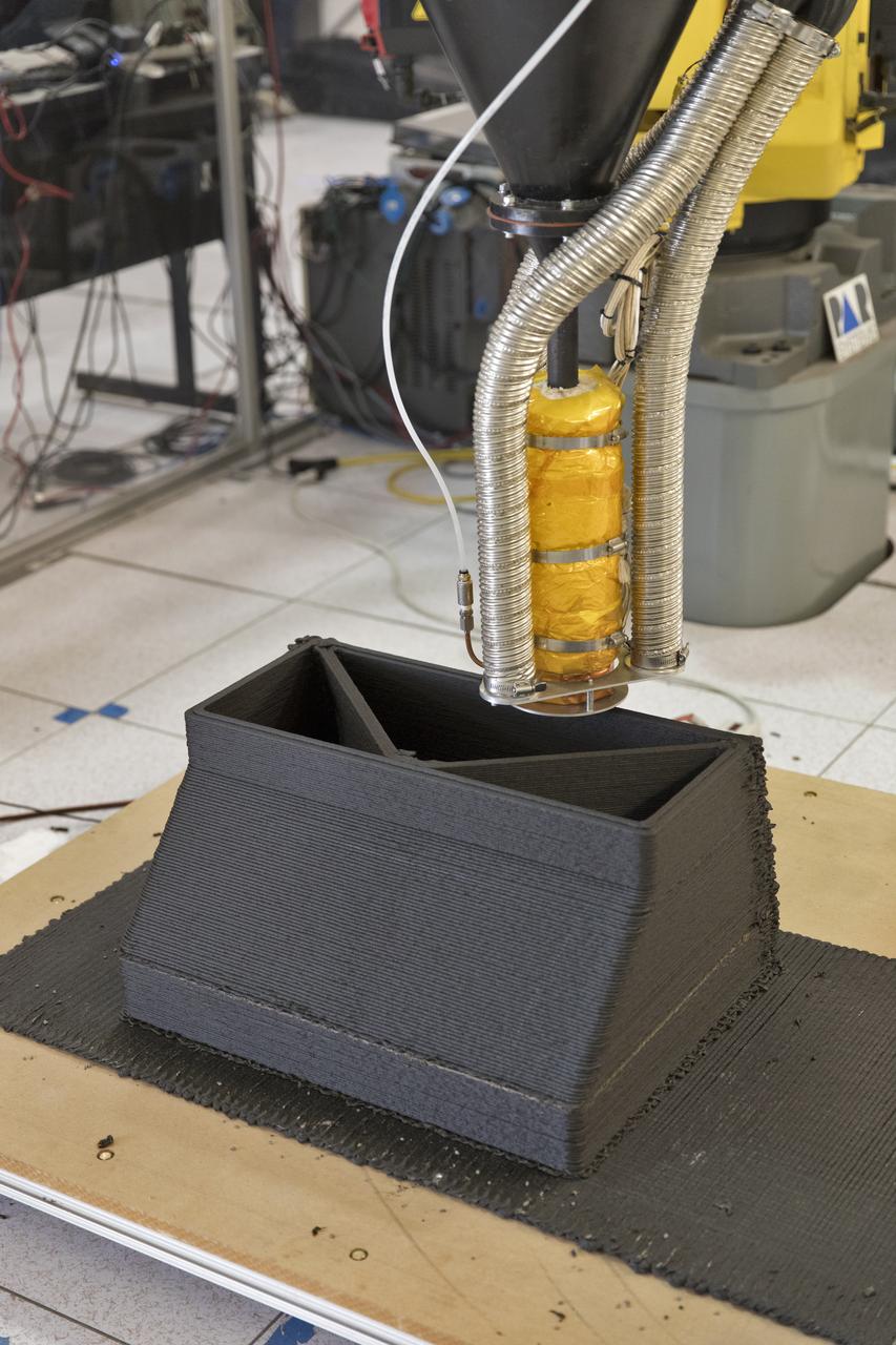
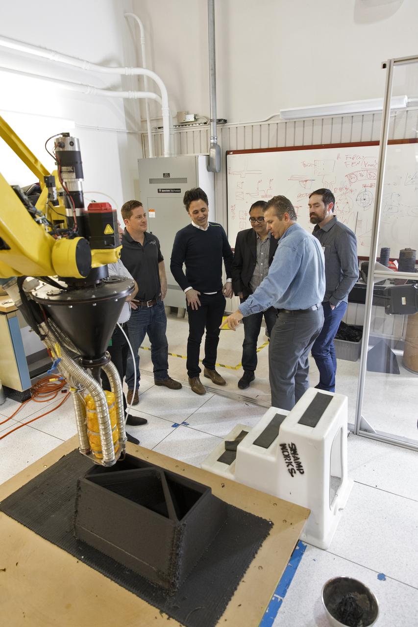
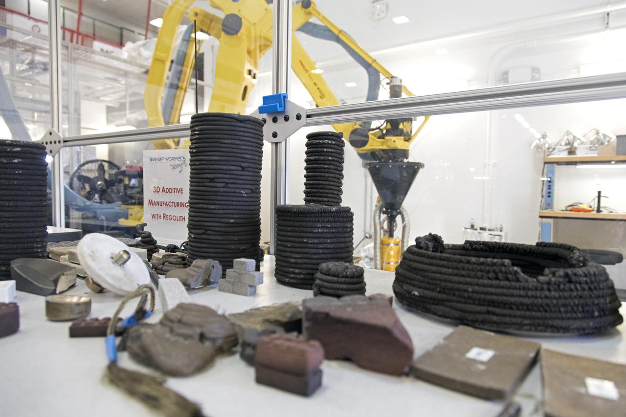
A Zero Launch Mass 3-D printer is being tested at the Swamp Works at NASA's Kennedy Space Center in Florida. The printer can be used for construction projects on the Moon and Mars. Zero launch mass refers to the fact that the printer uses pellets made from simulated lunar regolith, or dirt, and polymers. This will prove that space explorers can use resources at their destination instead of taking everything with them, saving them launch mass and money. The Kennedy team is working with Marshall Space Flight Center in Huntsville, Alabama, and the U.S. Army Corps of Engineers to develop a system that can 3-D print barracks in remote locations on Earth, using the resources they have where they are.
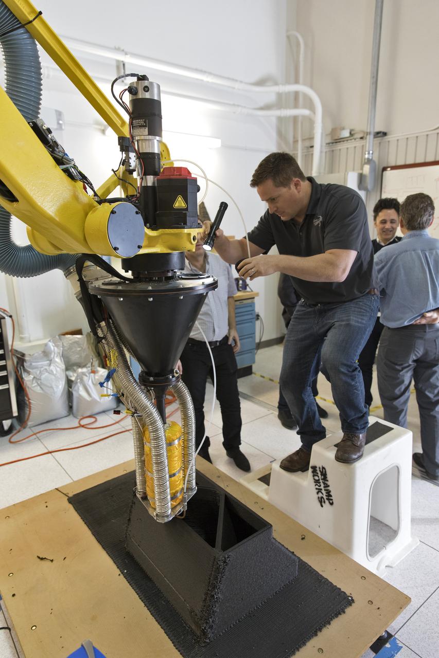
Researchers at NASA's Kennedy Space Center in Florida are developing a Zero Launch Mass 3-D printer at the center's Swamp Works. The printer can be used for construction projects on the Moon and Mars. Zero launch mass refers to the fact that the printer uses pellets made from simulated lunar regolith, or dirt, and polymers. This will prove that space explorers can use resources at their destination instead of taking everything with them, saving them launch mass and money. The Kennedy team is working with Marshall Space Flight Center in Huntsville, Alabama, and the U.S. Army Corps of Engineers to develop a system that can 3-D print barracks in remote locations on Earth, using the resources they have where they are.
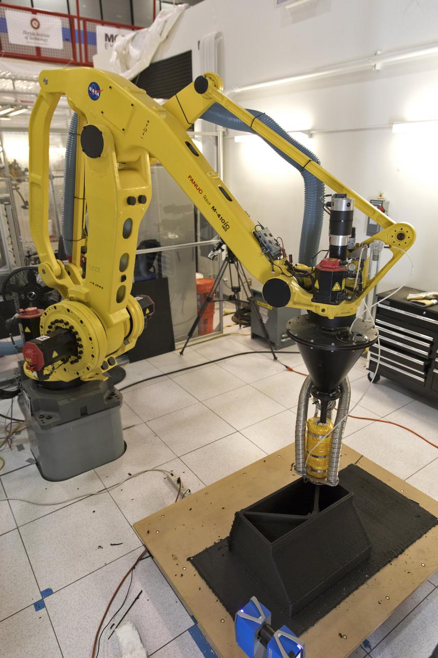
A Zero Launch Mass 3-D printer is being developed by researchers in Swamp Works at NASA's Kennedy Space Center in Florida. The printer can be used for construction projects on the Moon and Mars. Zero launch mass refers to the fact that the printer uses pellets made from simulated lunar regolith, or dirt, and polymers. This will prove that space explorers can use resources at their destination instead of taking everything with them, saving them launch mass and money. The Kennedy team is working with Marshall Space Flight Center in Huntsville, Alabama, and the U.S. Army Corps of Engineers to develop a system that can 3-D print barracks in remote locations on Earth, using the resources they have where they are.
Researchers demonstrate a Zero Launch Mass 3-D printer in Swamp Works at NASA's Kennedy Space Center in Florida. The printer can be used for construction projects on the Moon and Mars. Zero launch mass refers to the fact that the printer uses pellets made from simulated lunar regolith, or dirt, and polymers. This will prove that space explorers can use resources at their destination instead of taking everything with them, saving them launch mass and money. The Kennedy team is working with Marshall Space Flight Center in Huntsville, Alabama, and the U.S. Army Corps of Engineers to develop a system that can 3-D print barracks in remote locations on Earth, using the resources they have where they are.
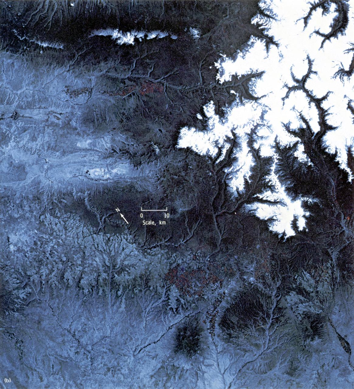
This EREP color infrared photograph of the Uncompahgre Plateau area of Colorado was taken in June of 1973 by the Earth Terrain Camera (Skylab EREP Experiment S190B) of the Skylab's Multi-spectral Photographic Facility during the Skylab-2 mission. Skylab stereoscopic data provided the best identification of vegetation complexes and delineation of vegetation boundaries, particularly in areas where changes in relief were related to changes in vegetation type (a common occurrence in wild-land vegetation communities).
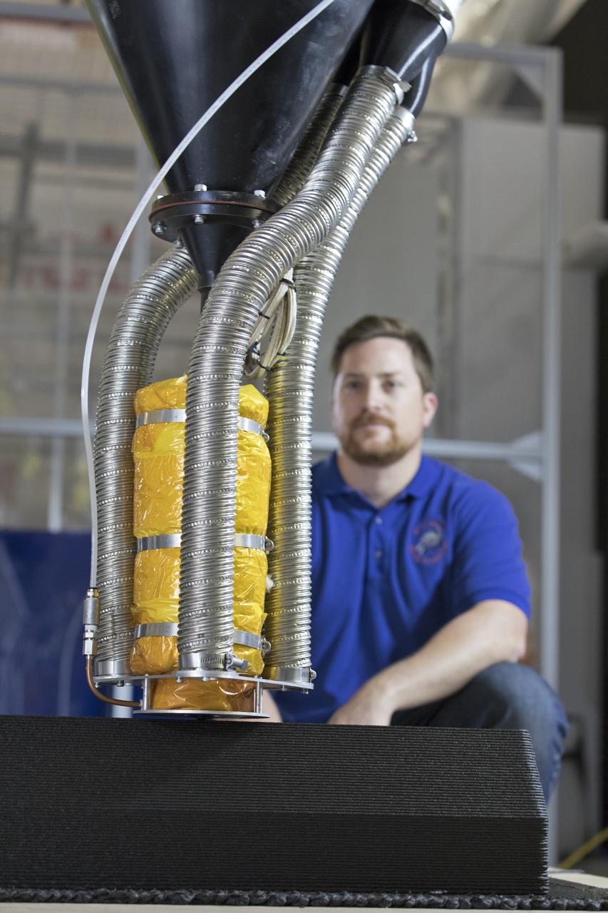
Nathan Gelino, a NASA research engineer at Kennedy Space Center in Florida, is working on a Zero Launch Mass 3-D printer in the center's Swamp Works that can be used for construction projects on the Moon and Mars, and even for troops in remote locations here on Earth. Zero launch mass refers to the fact that the printer uses pellets made from simulated lunar regolith, or dirt, and polymers to prove that space explorers can use resources at their destination instead of taking everything with them, saving them launch mass and money. Gelino and his team are working with Marshall Space Flight Center in Huntsville, Alabama, and the U.S. Army Corps of Engineers to develop a system that can 3-D print barracks in remote locations on Earth, using the resources they have where they are.
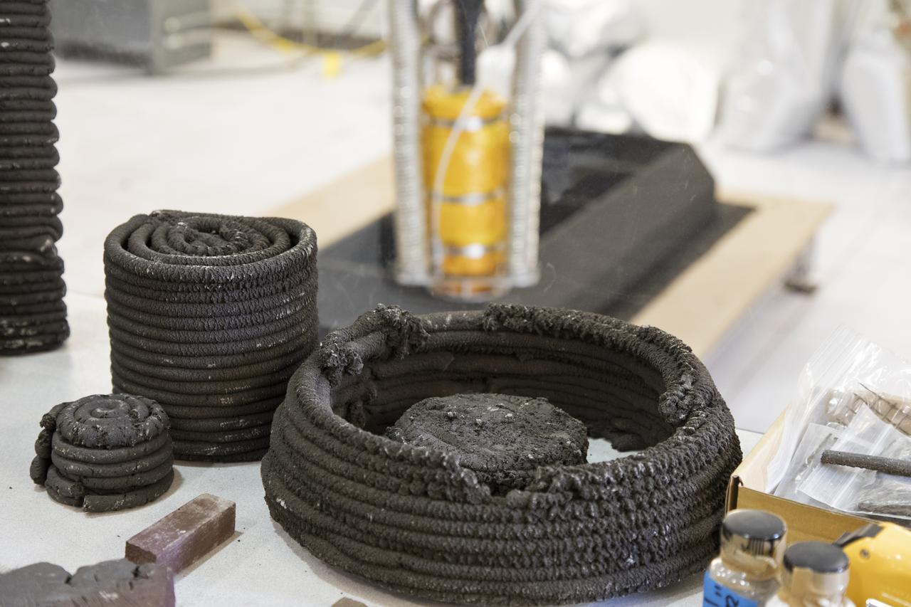
Pellets made from simulated lunar regolith, or dirt, and polymers are being used to test a Zero Launch Mass 3-D printer in the Swamp Works at NASA's Kennedy Space Center in Florida. The printer can be used for construction projects on the Moon and Mars, and even for troops in remote locations on Earth. Zero launch mass refers to the fact that the printer uses these pellets to prove that space explorers can use resources at their destination instead of taking everything with them, saving them launch mass and money. The group is working with Marshall Space Flight Center in Huntsville, Alabama, and the U.S. Army Corps of Engineers to develop a system that can 3-D print barracks in remote locations on Earth, using the resources they have where they are.
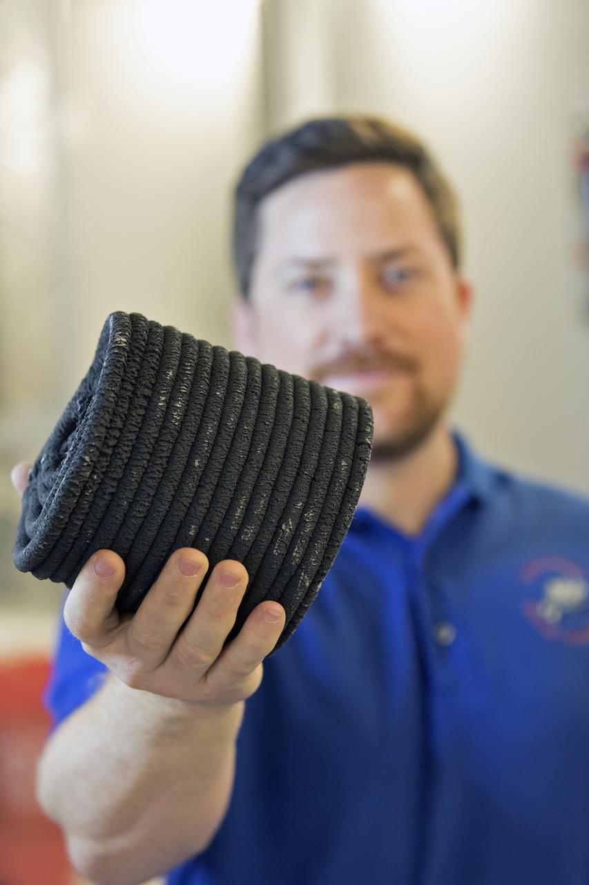
Nathan Gelino, a NASA research engineer at Kennedy Space Center in Florida displays a 3-D printed cylinder used for compression testing. Engineers at the center’s Swamp Works measured how much force it takes to break the structure before moving on to 3-D printing with a simulated lunar regolith, or dirt, and polymers. Next, Gelino and his group are working on a Zero Launch Mass 3-D printer that can be used for construction projects on the Moon and Mars, even for troops in remote locations here on Earth. Zero launch mass refers to the fact that the printer uses these pellets to prove that space explorers can use resources at their destination instead of taking everything with them, saving them launch mass and money. Gelino and his team are working with Marshall Space Flight Center in Huntsville, Alabama, and the U.S. Army Corps of Engineers to develop a system that can 3-D print barracks in remote locations on Earth, using the resources they have where they are.
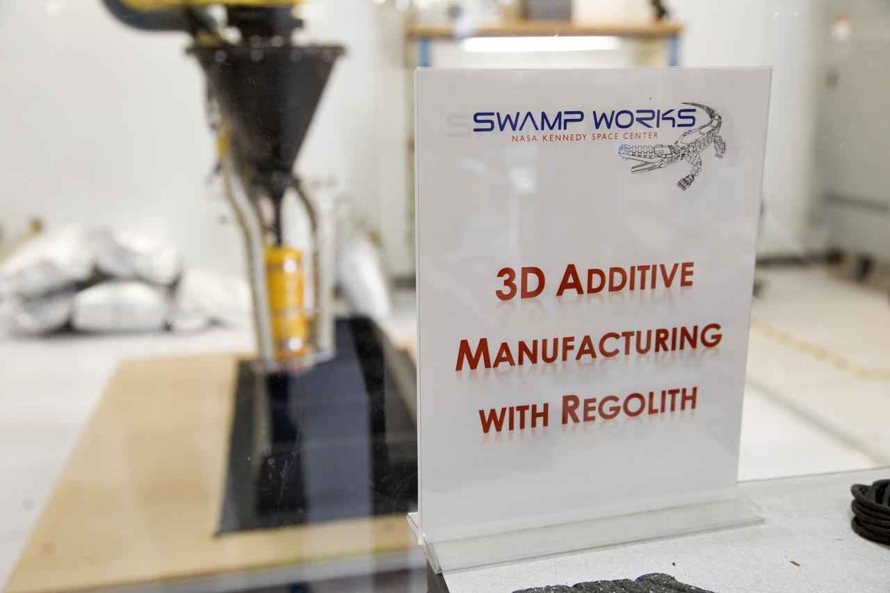
Research engineers at NASA's Kennedy Space Center in Florida are working on a Zero Launch Mass 3-D printer at the center's Swamp Works. The printer can be used for construction projects on the Moon and Mars, and even for troops in remote locations on Earth. Zero launch mass refers to the fact that the printer uses pellets made from simulated lunar regolith, or dirt, and polymers to prove that space explorers can use resources at their destination instead of taking everything with them, saving them launch mass and money. The group is working with Marshall Space Flight Center in Huntsville, Alabama, and the U.S. Army Corps of Engineers to develop a system that can 3-D print barracks in remote locations on Earth, using the resources they have where they are.
Research engineers at NASA's Kennedy Space Center in Florida are working on a Zero Launch Mass 3-D printer at the center's Swamp Works. The printer can be used for construction projects on the Moon and Mars, and even for troops in remote locations on Earth. Zero launch mass refers to the fact that the printer uses pellets made from simulated lunar regolith, or dirt, and polymers to prove that space explorers can use resources at their destination instead of taking everything with them, saving them launch mass and money. The group is working with Marshall Space Flight Center in Huntsville, Alabama, and the U.S. Army Corps of Engineers to develop a system that can 3-D print barracks in remote locations on Earth, using the resources they have where they are.
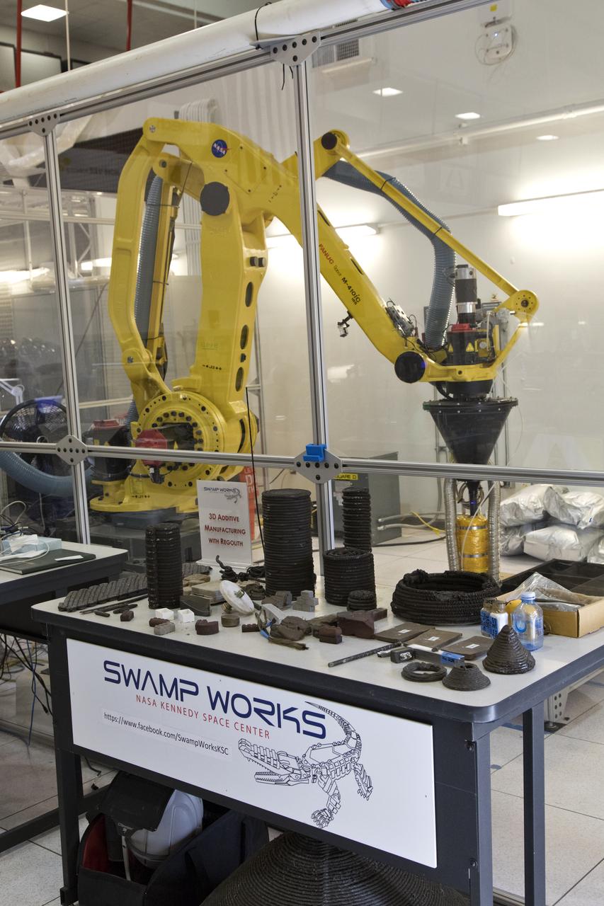
A Zero Launch Mass 3-D printer is being tested at the Swamp Works at NASA's Kennedy Space Center in Florida. The printer can be used for construction projects on the Moon and Mars, and even for troops in remote locations on Earth. Zero launch mass refers to the fact that the printer uses pellets made from simulated lunar regolith, or dirt, and polymers to prove that space explorers can use resources at their destination instead of taking everything with them, saving them launch mass and money. The group is working with Marshall Space Flight Center in Huntsville, Alabama, and the U.S. Army Corps of Engineers to develop a system that can 3-D print barracks in remote locations on Earth, using the resources they have where they are.
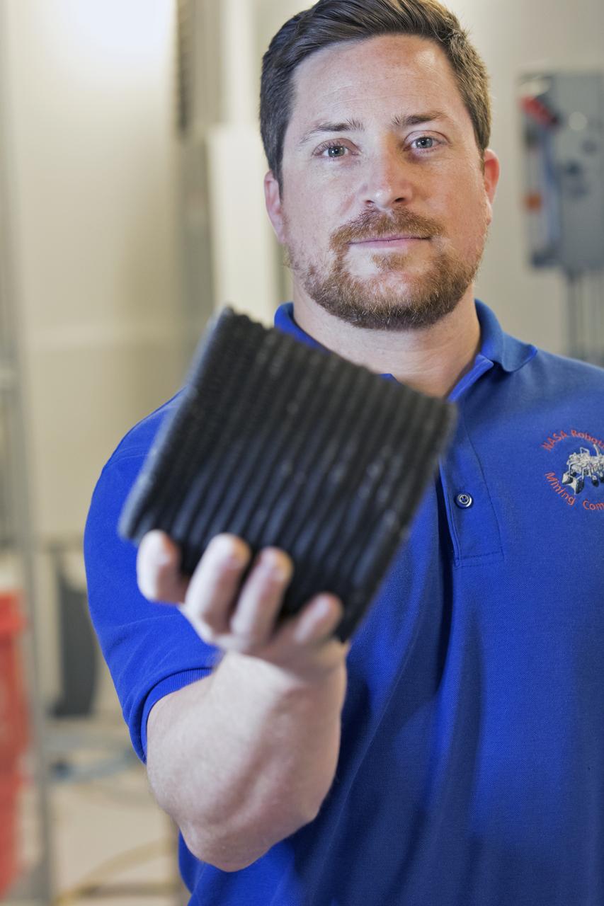
Nathan Gelino, a NASA research engineer at Kennedy Space Center in Florida displays a 3-D printed cylinder used for compression testing. Engineers at the center’s Swamp Works measured how much force it takes to break the structure before moving on to 3-D printing with a simulated lunar regolith, or dirt, and polymers. Next, Gelino and his group are working on a Zero Launch Mass 3-D printer that can be used for construction projects on the Moon and Mars, even for troops in remote locations here on Earth. Zero launch mass refers to the fact that the printer uses these pellets to prove that space explorers can use resources at their destination instead of taking everything with them, saving them launch mass and money. Gelino and his team are working with Marshall Space Flight Center in Huntsville, Alabama, and the U.S. Army Corps of Engineers to develop a system that can 3-D print barracks in remote locations on Earth, using the resources they have where they are.