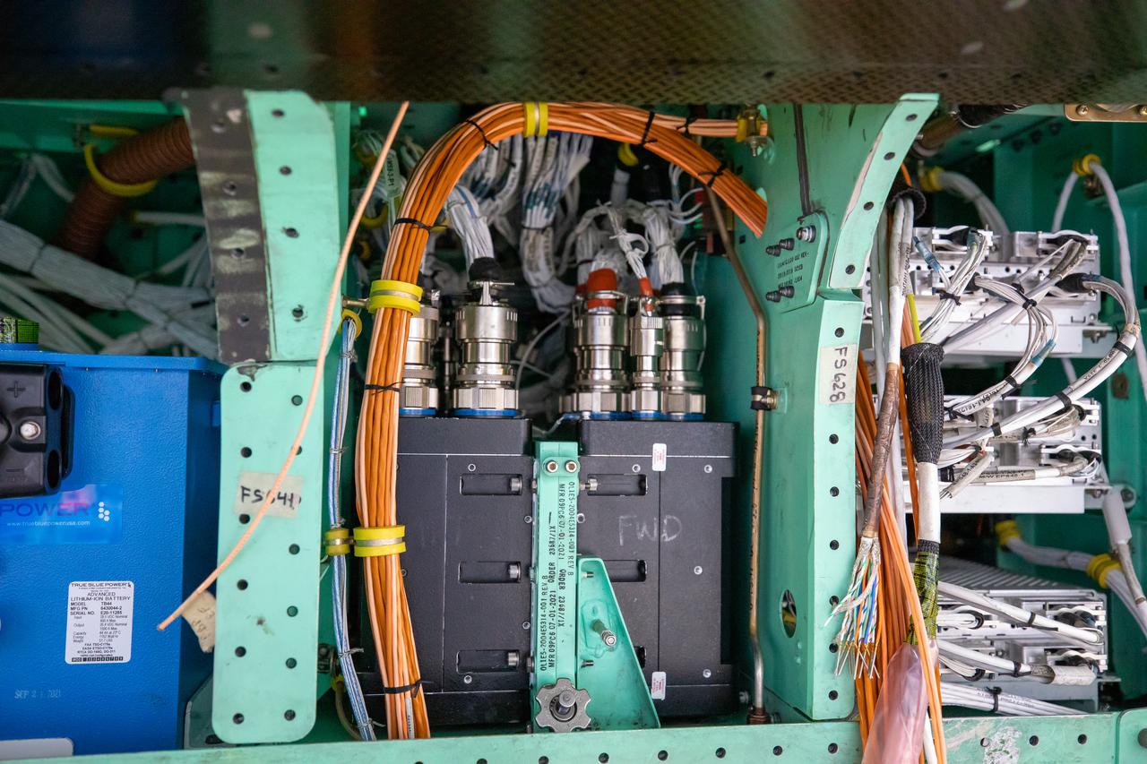
This is a closeup view of the inner workings of the X-59 aircraft. Visible are one the plane’s three lithium-ion batteries (blue box), electrical power system and other wiring components including the vehicle management systems computers (two black boxes) and the white wirings which assist in providing the power that is needed for the aircraft to function in flight. All of these components are essential to maintaining and monitoring the X-59 once it takes to the skies. The X-59 is the centerpiece of the Quesst mission which plans to help enable commercial supersonic air travel over land.
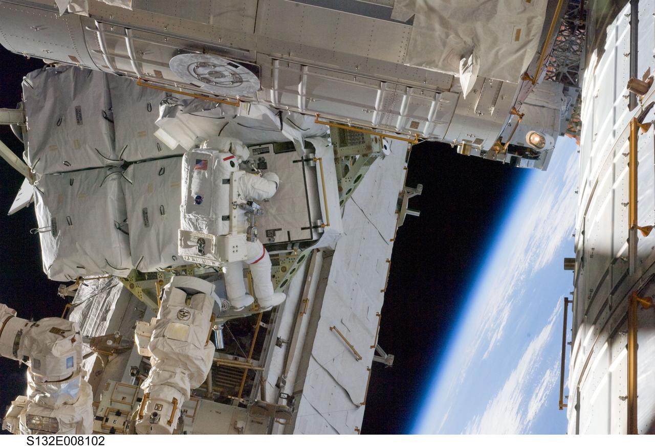
S132-E-008102 (17 May 2010) --- NASA astronaut Steve Bowen, STS-132 mission specialist, participates in the mission's first session of extravehicular activity (EVA) as construction and maintenance continue on the International Space Station. During the seven-hour, 25-minute spacewalk, Bowen and NASA astronaut Garrett Reisman (out of frame), mission specialist, loosened bolts holding six replacement batteries, installed a second antenna for high-speed Ku-band transmissions and adding a spare parts platform to Dextre, a two-armed extension for the station’s robotic arm.
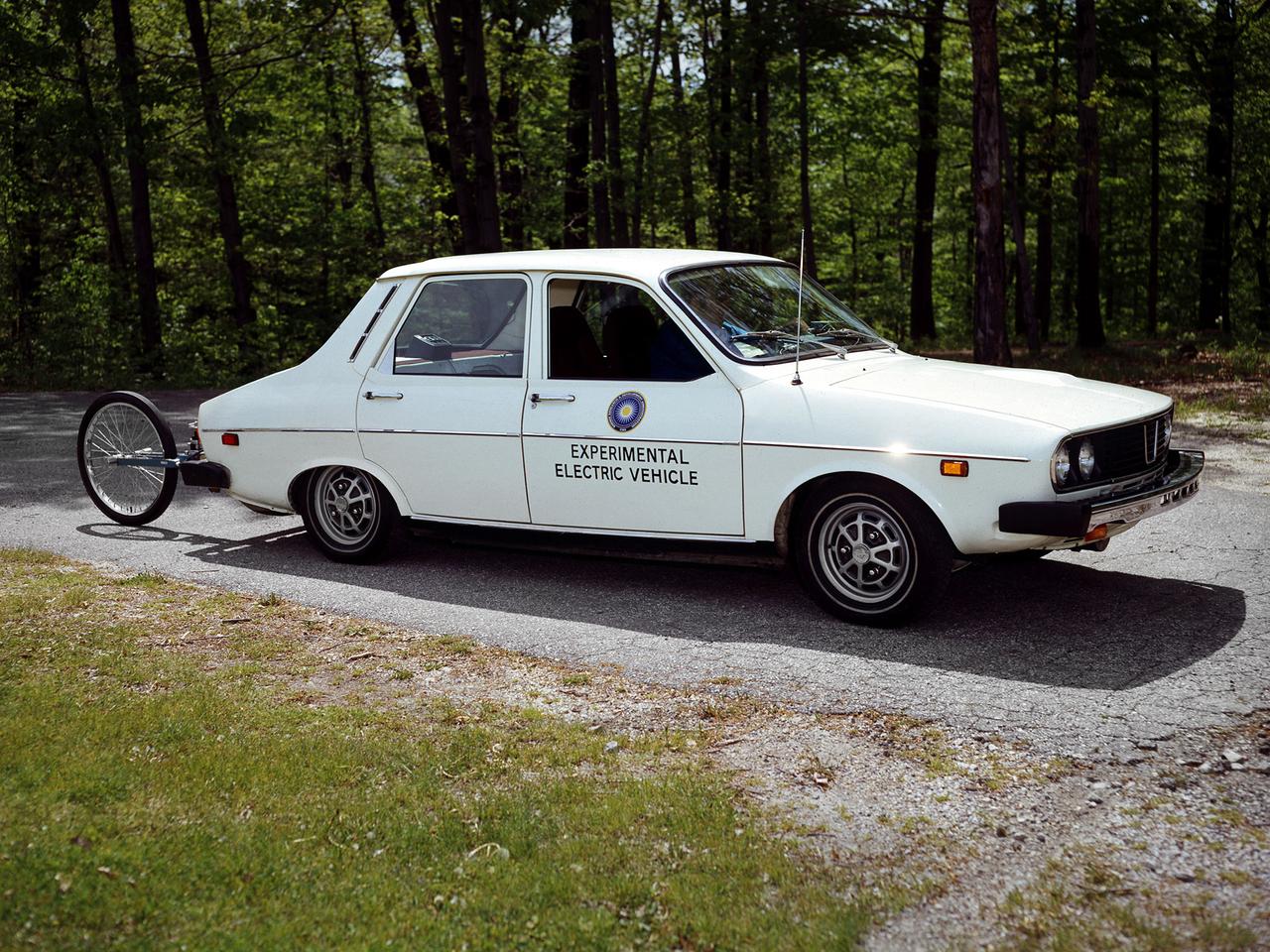
The National Aeronautics and Space Administration (NASA) Lewis Research Center tested 16 commercially-manufactured electric vehicles, including this Metro, during the mid-1970s. Lewis and the Energy Research and Development Administration (ERDA) engaged in several energy-related programs in the mid-1970s, including the Electric Vehicle Project. NASA and ERDA undertook the program in 1976 to determine the state of the current electric vehicle technology. As part of the project, Lewis and ERDA tested every commercially available electric car model. Electric Vehicle Associates, located in a Cleveland suburb, modified a Renault 12 vehicle to create this Metro. Its 1040-pound golfcart-type battery provided approximately 106 minutes of operation. The tests analyzed the vehicle’s range, acceleration, coast-down, braking, and energy consumption. Some of the vehicles had analog data recording systems to measure the battery during operation and sensors to determine speed and distance. The researchers found the performance of the different vehicles varied significantly. In general, the range, acceleration, and speed were lower than that found on conventional vehicles. They also found that traditional gasoline-powered vehicles were as efficient as the electric vehicles. The researchers concluded, however, that advances in battery technology and electric drive systems would significantly improve efficiency and performance.
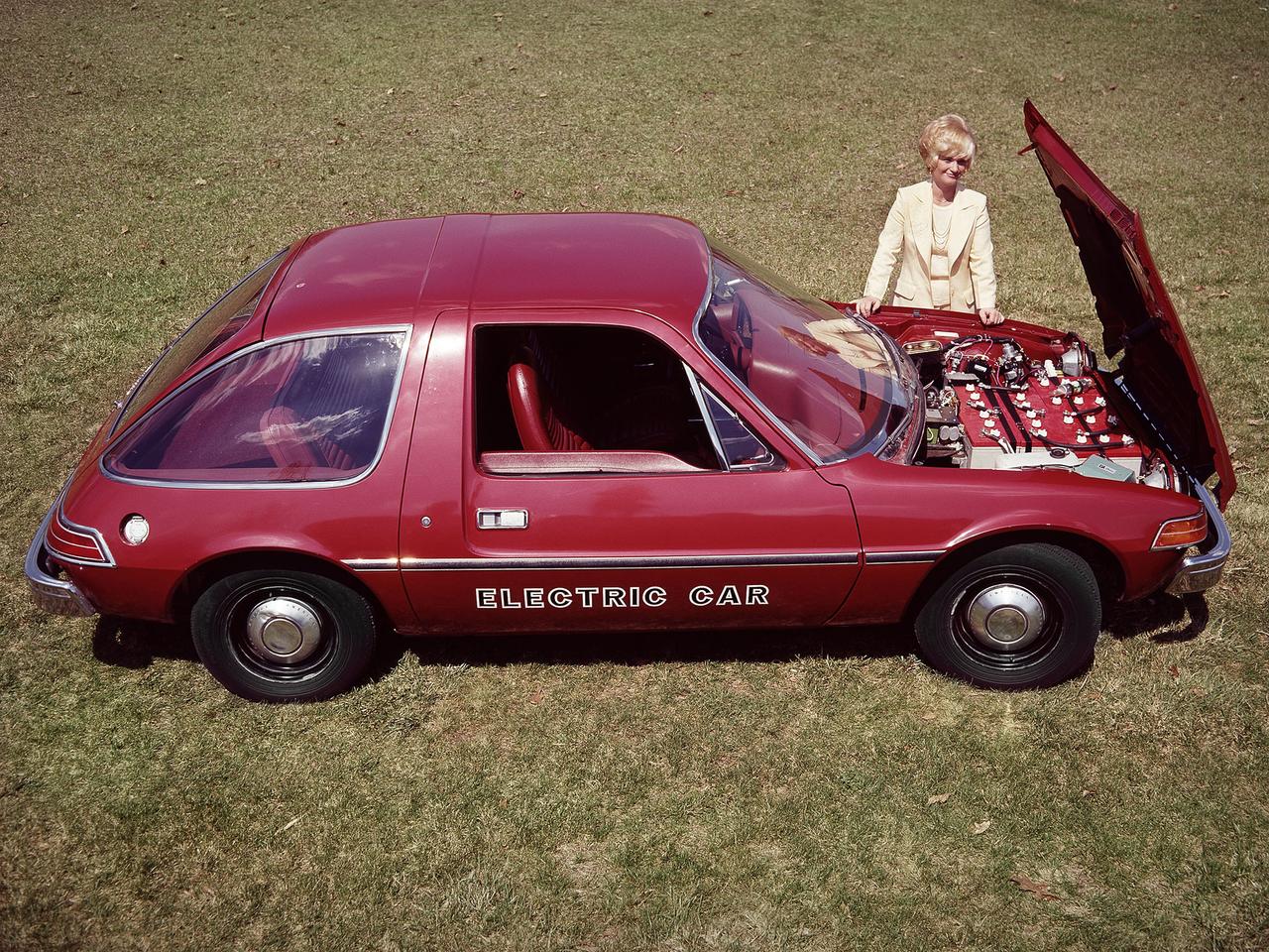
The National Aeronautics and Space Administration (NASA) Lewis Research Center tested 16 commercially-manufactured electric vehicles, including this modified Pacer, during the mid-1970s. The Electric Vehicle Project was just one of several energy-related programs that Lewis and the Energy Research and Development Administration (ERDA) undertook in the mid-1970s. NASA and ERDA embarked on this program in 1976 to determine the state of the current electric vehicle technology. As part of the project, Lewis tested a fleet composed of every commercially available electric car. The Cleveland-area Electric Vehicle Associates modified an American Motors Pacer vehicle to create this Change-of-Pace Coupe. It was powered by twenty 6-volt batteries whose voltage could be varied by a foot control. The tests analyzed the vehicle’s range, acceleration, coast-down, braking, and energy consumption. Some of the vehicles had analog data recording systems to measure the battery during operation and sensors to determine speed and distance. Lewis researchers found that the vehicle performance varied significantly from model to model. In general, the range, acceleration, and speed were lower than conventional vehicles. They also found that traditional gasoline-powered vehicles were as efficient as the electric vehicles. The researchers concluded, however, that advances in battery technology and electric drive systems would significantly improve the performance and efficiency.
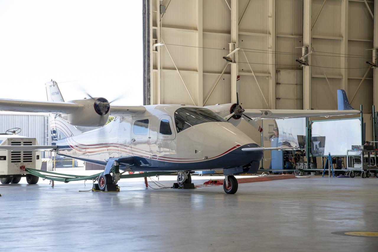
NASA's all-electric X-57 Maxwell aircraft tests the motors with the battery packs installed on the aircraft at NASA's Armstrong Flight Research Center in California. A goal of the X-57 project is to help the Federal Aviation Administration set certification standards for emerging electric aircraft markets.
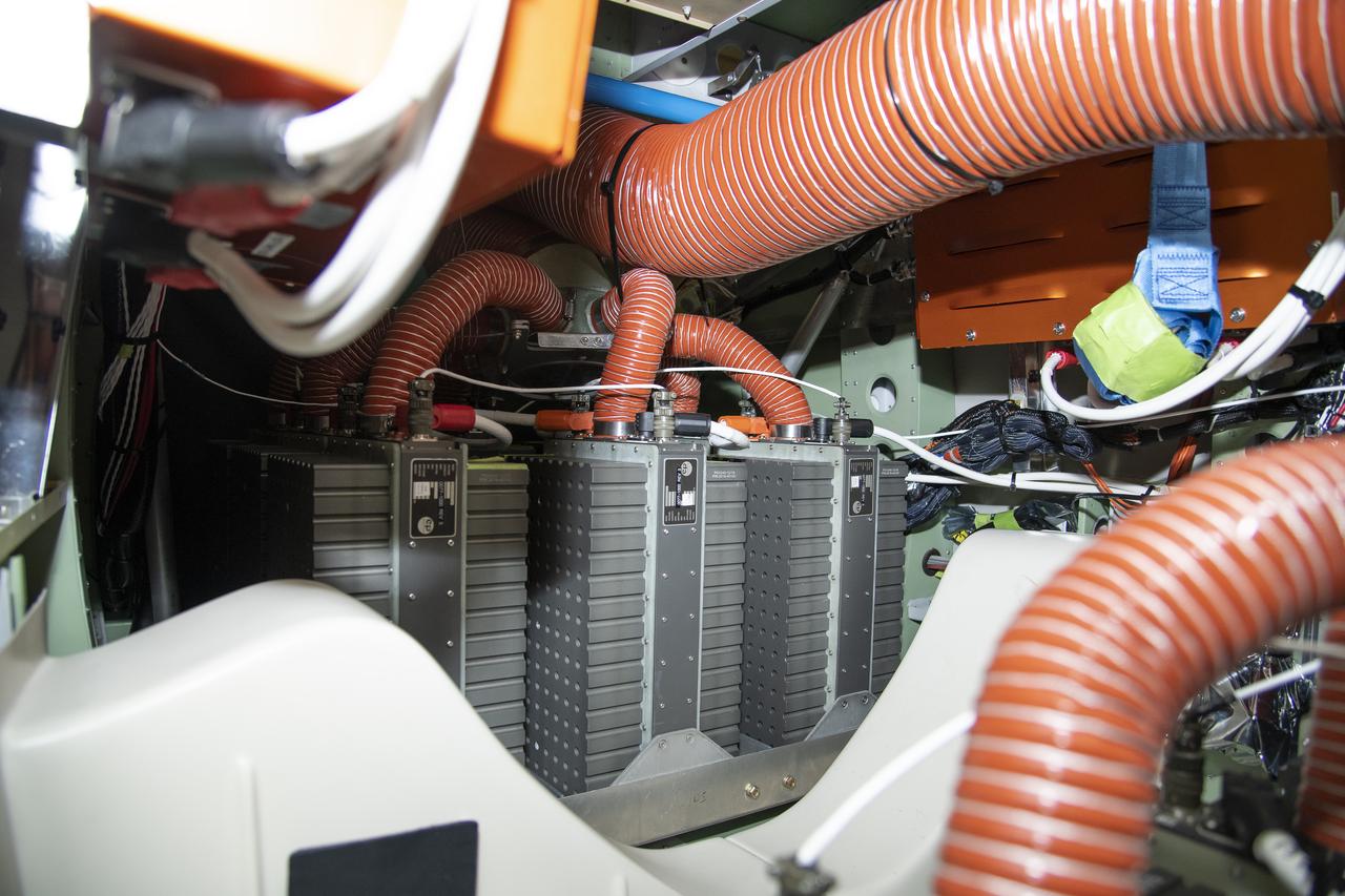
NASA's all-electric X-57 project team installed two 400-pound lithium-ion battery packs in the cabin of the plane in 2022 at NASA's Armstrong Flight Research Center in California. The X-57 project team repeatedly tested the batteries to ensure they can safely power the aircraft for an entire flight, and designed custom, lightweight cases to keep the batteries secure.
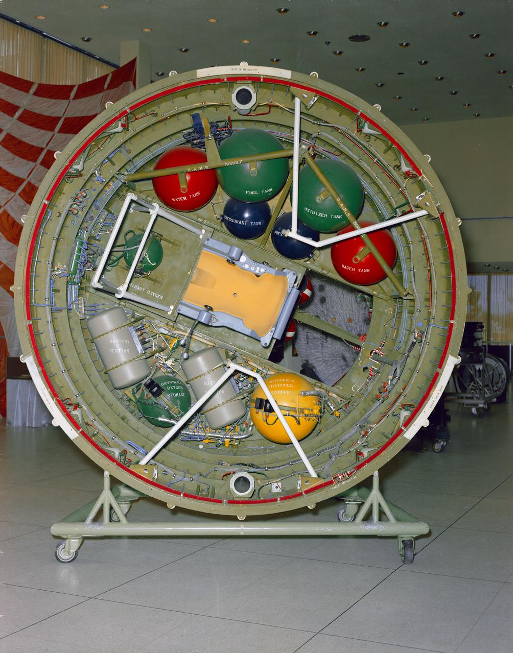
S66-22686 (March 1966) --- Mock-up of the adapter equipment section to be used on the Gemini-9 spaceflight. This section provides volume and attach points for several system modules, including Orbit Attitude Maneuver System, Environmental Control System primary oxygen supply, batteries, coolant, and electrical and electric components. This section will also hold the Astronaut Maneuvering Unit (AMU) backpack (center). Photo credit: NASA

This is the crew insignia for STS-97 which delivered, assembled, and activated the U.S. electrical power system onboard the International Space Station (ISS). The electrical power system, which is built into a 47-foot integrated truss structure known as P6, consists of solar arrays, radiators, batteries, and electronics. P6 was prepared for subsequent deployments of larger solar arrays and radiator, a critical step in the activation of the electrical power system that will eventually provide the power necessary for the first ISS crews to live and work in the U.S. segment. The crew patch depicts the space shuttle docked to the ISS in low Earth orbit after the activation of the P6 electrical power system. Gold and silver were used to highlight the portion of the ISS that were installed by the STS-97 crew. The sun, central to the design, is the source of energy for the ISS. The crew member names surround the outer border of the patch.
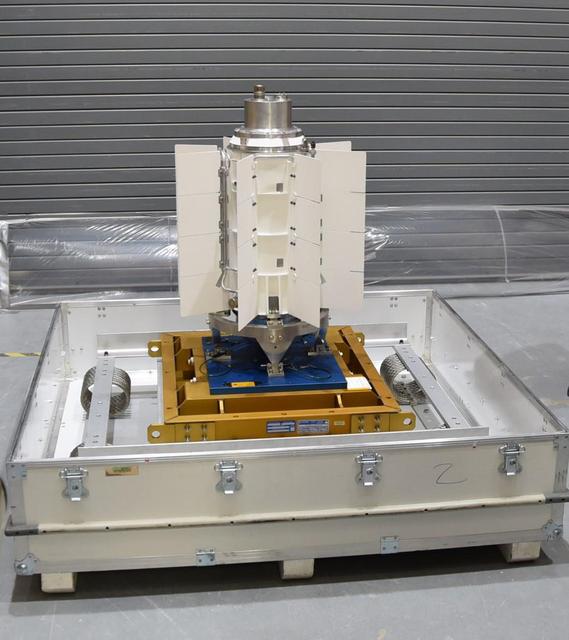
The electricity for NASA's Mars 2020 rover is provided by a power system called a Multi-Mission Radioisotope Thermoelectric Generator, or MMRTG. Essentially a nuclear battery, an MMRTG uses the heat from the natural radioactive decay of plutonium-238 to generate about 110 watts of electricity at the start of a mission. Besides generating electrical power, the MMRTG produces heat. Some of this heat can be used to maintain the rover's systems at the proper operating temperatures in the frigid cold of space and on the surface of Mars. This device, seen here before fueling and testing at the U.S. Department of Energy's Idaho National Laboratory, has "fins" that radiate excess heat. MMRTGs are provided to NASA for civil space applications by the U.S. Department of Energy (DOE). The radioisotope fuel is inserted into the MMRTG at the DOE's Idaho National Laboratory before the MMRTG is shipped to the launch site. Electrically heated versions of the MMRTG are used at JPL to verify and practice integration of the power system with the rover. https://photojournal.jpl.nasa.gov/catalog/PIA23306
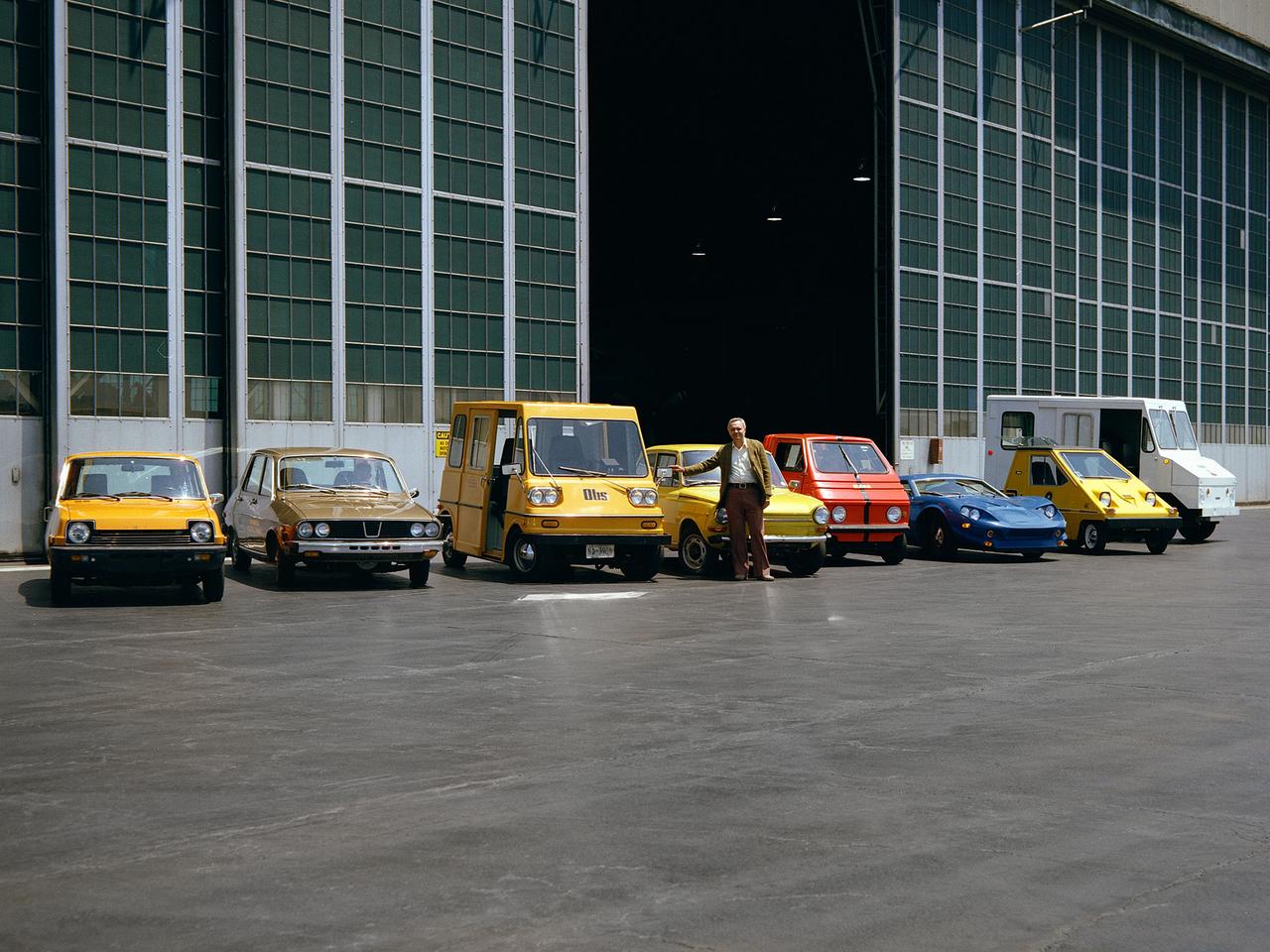
The National Aeronautics and Space Administration (NASA) Lewis Research Center tested 16 commercially-manufactured electric vehicles, including these, during the mid-1970s. Lewis and the Energy Research and Development Administration (ERDA) engaged in several energy-related programs in the mid-1970s, including the Electric Vehicle Project. NASA and ERDA undertook the program in 1976 to determine the state of the current electric vehicle technology. The tests were primarily conducted on a 7.5-mile track at the Transportation Research Center located approximately 160 miles southwest of Cleveland, Ohio. Some of the vehicles had analog data recording systems to measure the battery during operation and sensors to determine speed and distance. The tests analyzed the vehicle’s range, acceleration, coast-down, braking, and energy consumption. From left to right: RIPP-Electric, EVA Contactor, Otis P-500, C.H. Waterman DAF, Zagato Elcar, unknown, Sebring-Vanguard Citicar, and Hattronic Minivan
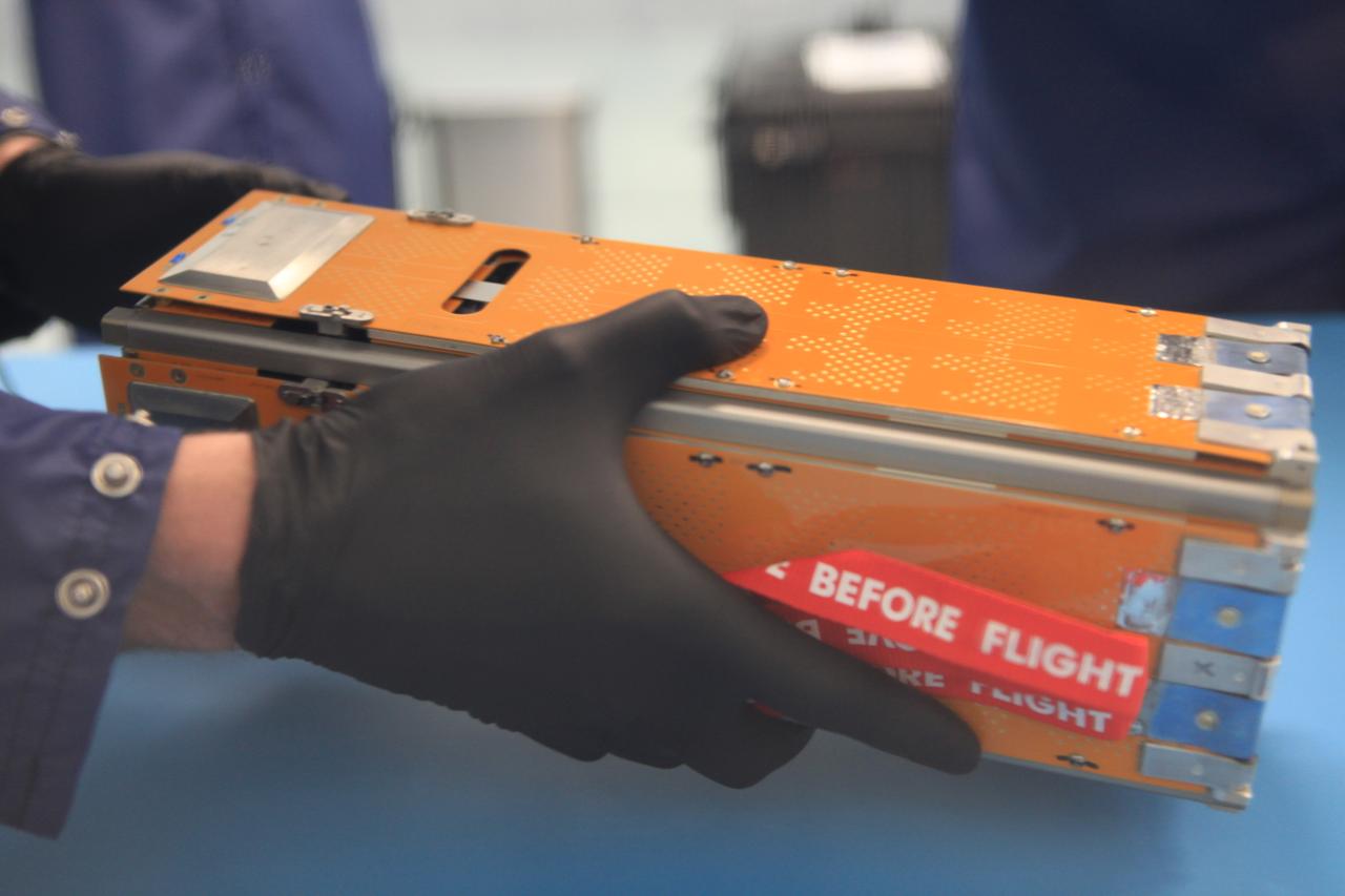
The Advanced Electrical Bus (ALBus) mission is a technology demonstration of resettable Shape Memory Alloy (SMA) mechanisms for deployable solar arrays and a pathfinder for high power density CubeSats. The mission has two primary objectives. The first is to demonstrate the functionality of the novel SMA activated solar array mechanisms in the on-orbit environment. The second objective is to assess the system level ability to charge a high capacity battery, distribute 100 W of electrical power and thermally control the 3-U CubeSat system. Performance from the mission will be used to mature the SMA mechanism designs for CubeSat applications and plan for future high power density CubeSat missions.
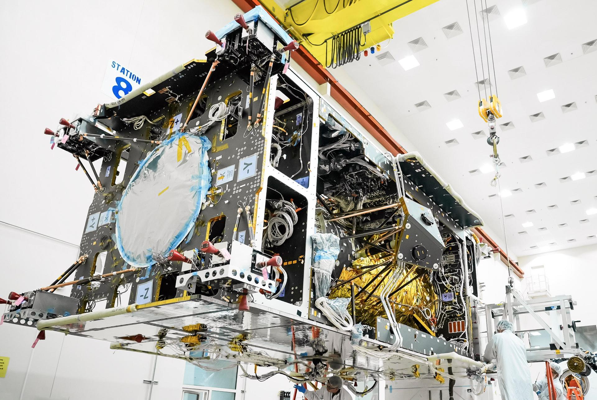
Gateway’s Power and Propulsion Element (PPE) undergoes battery installations at Lanteris Space Systems in Palo Alto, California, in January 2026. PPE is a 60-kilowatt solar electric propulsion spacecraft that will supply the lunar space station with power, high-rate communications, attitude control, orbit maintenance, and orbit transfer capabilities. Its design is based on Lanteris Space Systems’ commercial 1300 bus, enhanced with the most powerful Advanced Electric Propulsion System (AEPS) thrusters and the largest roll-out solar arrays (ROSAs) ever developed. Lanteris Space Systems is the lead industry partner for PPE’s design, manufacturing, and integration.
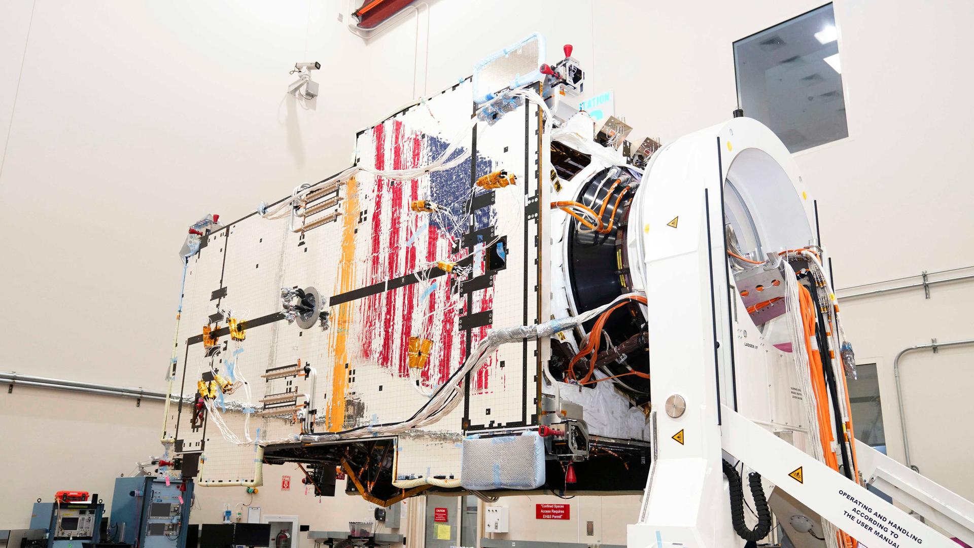
Gateway’s Power and Propulsion Element (PPE) undergoes battery installations at Lanteris Space Systems in Palo Alto, California, in January 2026. PPE is a 60-kilowatt solar electric propulsion spacecraft that will supply the lunar space station with power, high-rate communications, attitude control, orbit maintenance, and orbit transfer capabilities. Its design is based on Lanteris Space Systems’ commercial 1300 bus, enhanced with the most powerful Advanced Electric Propulsion System (AEPS) thrusters and the largest roll-out solar arrays (ROSAs) ever developed. Lanteris Space Systems is the lead industry partner for PPE’s design, manufacturing, and integration.
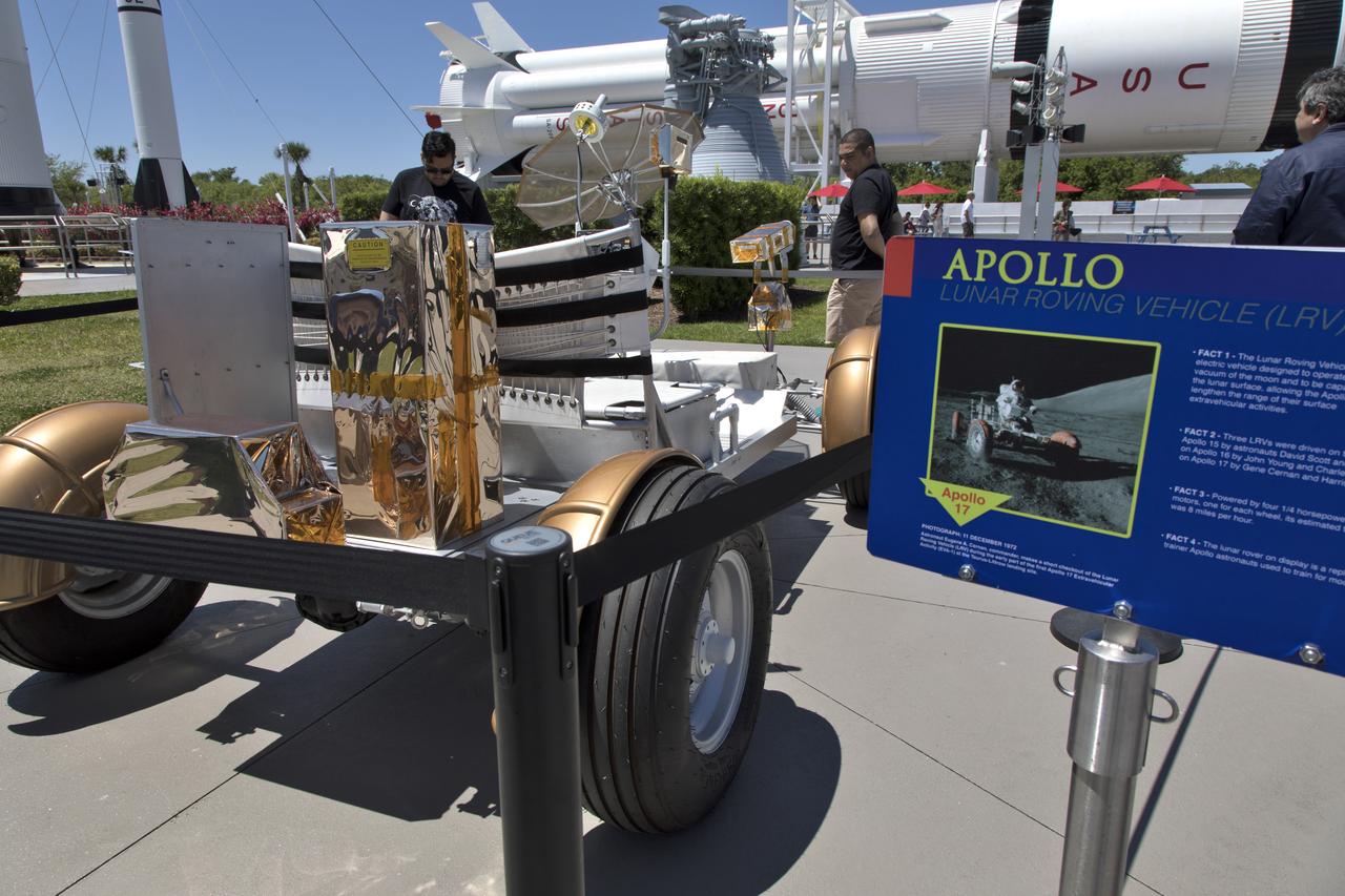
During the annual Earth Day celebration at the Kennedy Space Center Visitor Complex, guests have an opportunity to get an up-close look at experimental electric vehicles and see and Apollo era Lunar Roving Vehicle used in astronaut training. The battery-operated car was used on Apollos 15, 16 and 17 in 1971 and 1972. The two-day event featured approximately 50 exhibitors offering information on a variety of topics, including electric vehicles, sustainable lighting, renewable energy, Florida-friendly landscaping tips, Florida’s biking trails and more.
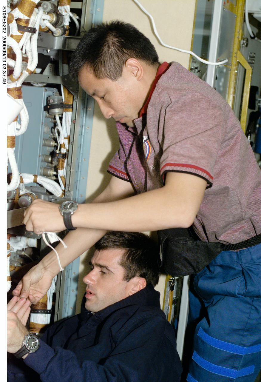
S106-E-5202 (13 September 2000) --- Cosmonaut Yuri I. Malenchenko, mission specialist representing the Russian Aviation and Space Agency, teams up with astronaut Edward T. Lu for some electrical work aboard the Zvezda service module on the International Space Station (ISS). Electrical work was the hallmark of the day as four of the mission specialists aboard ISS (temporarily docked with the Space Shuttle Atlantis) replaced batteries inside the Zarya and Zvezda modules while supply transfer continued around them. Astronaut Edward T. Lu, is out of frame at right.
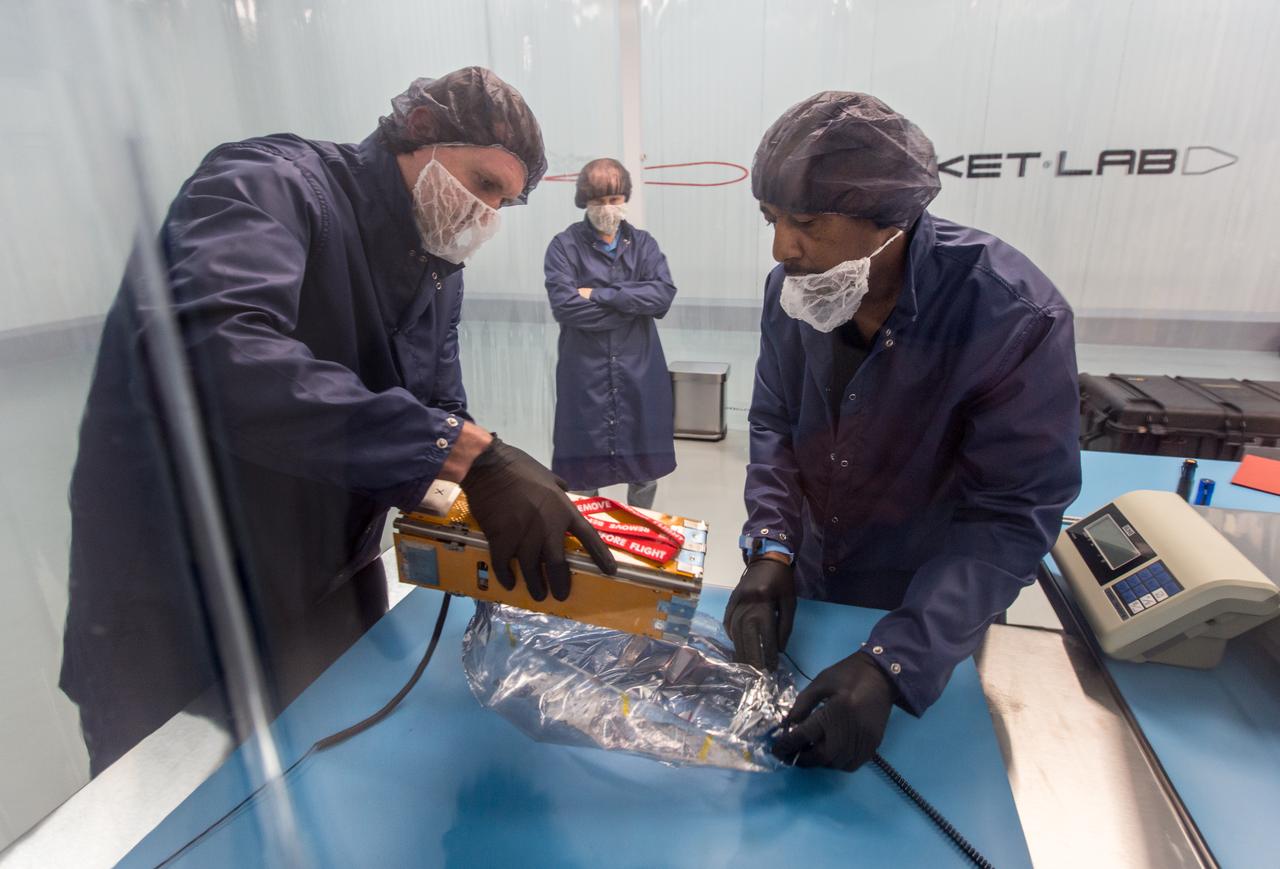
The Advanced Electrical Bus (ALBus) mission is a technology demonstration of resettable Shape Memory Alloy (SMA) mechanisms for deployable solar arrays and a pathfinder for high power density CubeSats. The mission has two primary objectives. The first is to demonstrate the functionality of the novel SMA activated solar array mechanisms in the on-orbit environment. The second objective is to assess the system level ability to charge a high capacity battery, distribute 100 W of electrical power and thermally control the 3-U CubeSat system. Performance from the mission will be used to mature the SMA mechanism designs for CubeSat applications and plan for future high power density CubeSat missions.
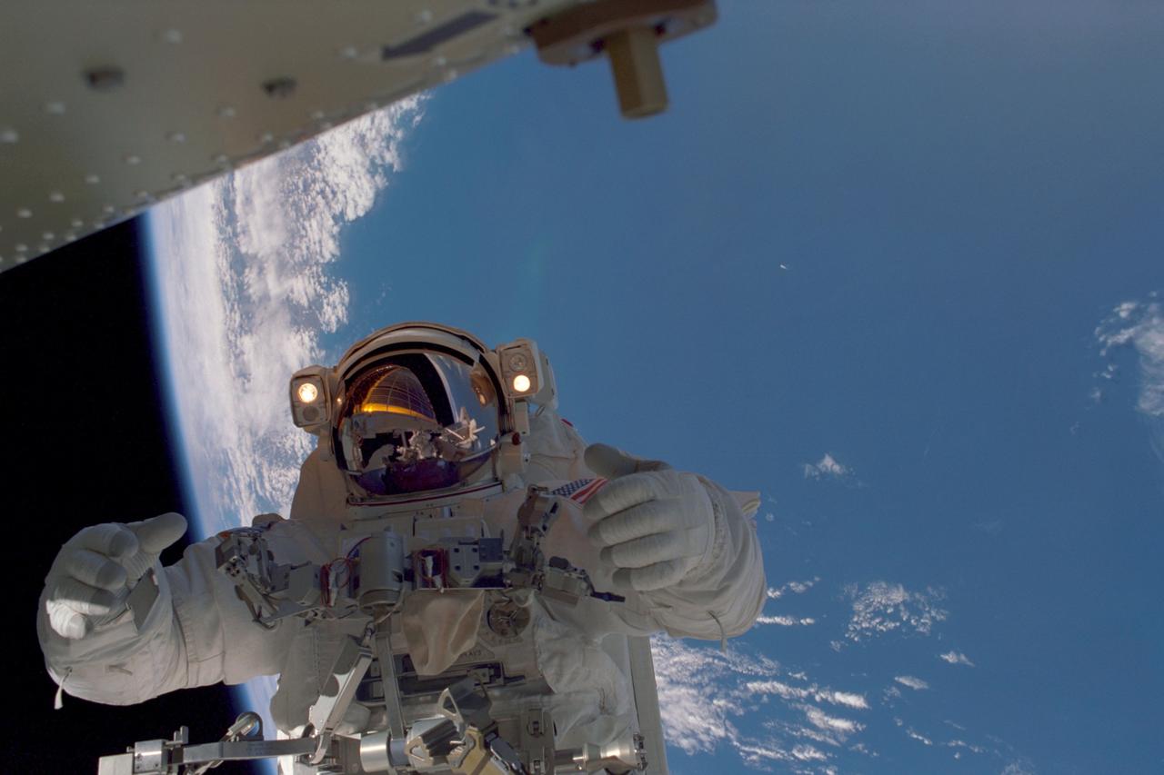
In this image, planet Earth, some 235 statute miles away, forms the back drop for this photo of STS-97 astronaut and mission specialist Joseph R. Tanner, taken during the third of three space walks. The mission's goal was to perform the delivery, assembly, and activation of the U.S. electrical power system onboard the International Space Station (ISS). The electrical power system, which is built into a 73-meter (240-foot) long solar array structure consists of solar arrays, radiators, batteries, and electronics. The entire 15.4-metric ton (17-ton) package is called the P6 Integrated Truss Segment, and is the heaviest and largest element yet delivered to the station aboard a space shuttle. The electrical system will eventually provide the power necessary for the first ISS crews to live and work in the U.S. segment. The STS-97 crew of five launched aboard the Space Shuttle Orbiter Endeavor on November 30, 2000 for an 11 day mission.
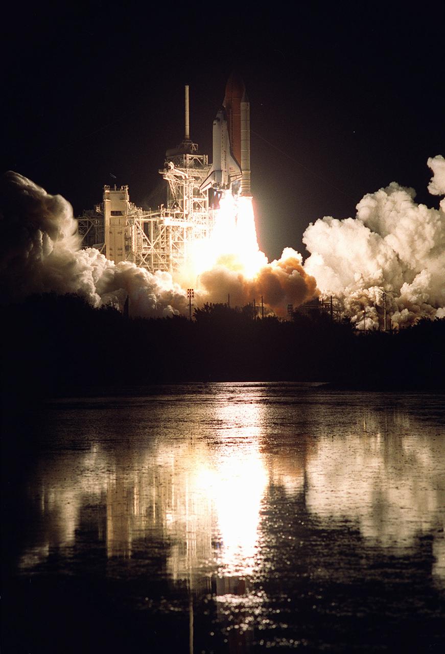
Nearby waters reflect the flames of the Space Shuttle Endeavor as she lifts off November 30, 2000, carrying the STS-97 crew of five. The STS-97 mission's primary objective was the delivery, assembly, and activation of the U.S. electrical power system onboard the International Space Station (ISS). The electrical power system, which is built into a 73-meter (240-foot) long solar array structure, consists of solar arrays, radiators, batteries, and electronics. The entire 15.4-metric ton (17-ton) package is called the P6 Integrated Truss Segment and is the heaviest and largest element yet delivered to the station aboard a space shuttle. The electrical system will eventually provide the power necessary for the first ISS crews to live and work in the U.S. segment.
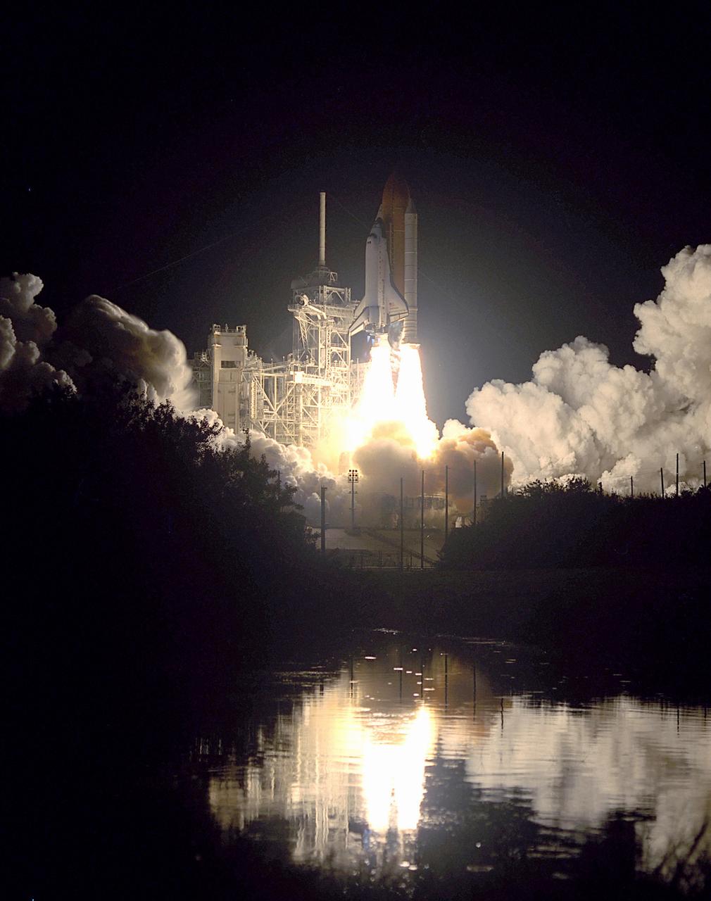
Nearby waters reflect the flames of the Space Shuttle Endeavor as she lifts off November 30, 2000 carrying the STS-97 crew of five. The STS-97 mission's primary objective was the delivery, assembly, and activation of the U.S. electrical power system onboard the International Space Station (ISS). The electrical power system, which is built into a 73-meter (240-foot) long solar array structure, consists of solar arrays, radiators, batteries, and electronics. The entire 15.4-metric ton (17-ton) package is called the P6 Integrated Truss Segment, and is the heaviest and largest element yet delivered to the station aboard a space shuttle. The electrical system will eventually provide the power necessary for the first ISS crews to live and work in the U.S. segment.
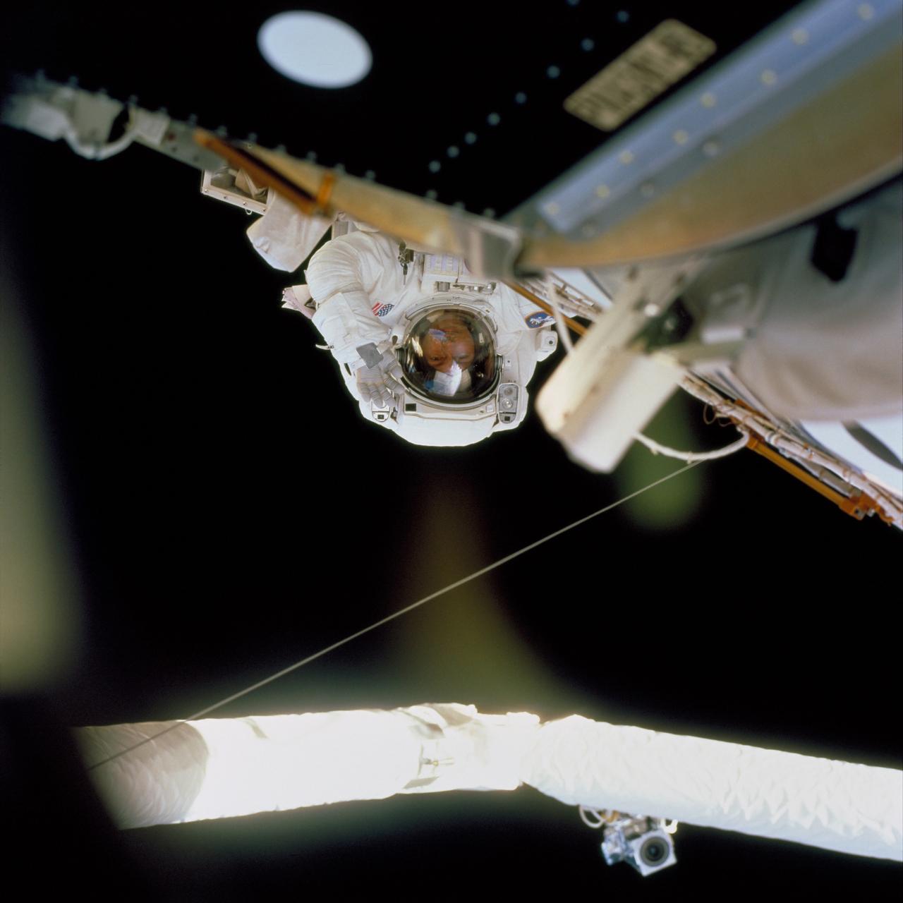
In this image, STS-97 astronaut and mission specialist Carlos I. Noriega waves at a crew member inside Endeavor's cabin during the mission's final session of Extravehicular Activity (EVA). Launched aboard the Space Shuttle Orbiter Endeavor on November 30, 2000, the STS-97 mission's primary objective was the delivery, assembly, and activation of the U.S. electrical power system onboard the International Space Station (ISS). The electrical power system, which is built into a 73-meter (240-foot) long solar array structure consists of solar arrays, radiators, batteries, and electronics. The entire 15.4-metric ton (17-ton) package is called the P6 Integrated Truss Segment, and is the heaviest and largest element yet delivered to the station aboard a space shuttle. The electrical system will eventually provide the power necessary for the first ISS crews to live and work in the U.S. segment.
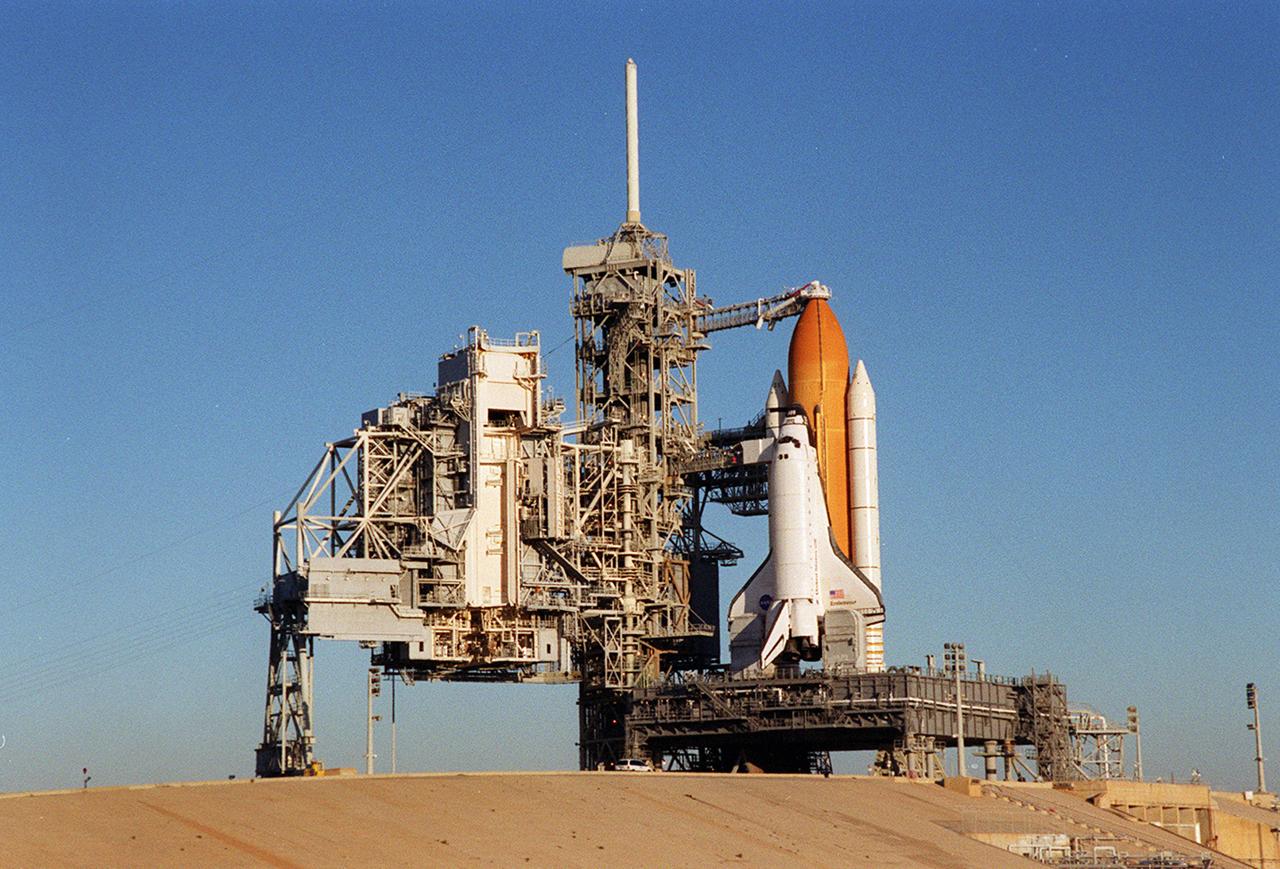
Back dropped by a cloudless blue sky, Space Shuttle Endeavor stands ready for launch after the rollback of the Rotating Service Structure, at left. The orbiter launched that night carrying the STS-97 crew of five. The STS-97 mission's primary objective was the delivery, assembly, and activation of the U.S. electrical power system onboard the International Space Station (ISS). The electrical power system, which is built into a 73-meter (240-foot) long solar array structure, consists of solar arrays, radiators, batteries, and electronics. The entire 15.4-metric ton (17-ton) package is called the P6 Integrated Truss Segment, and is the heaviest and largest element yet delivered to the station aboard a space shuttle. The electric system will eventually provide the power necessary for the first ISS crews to live and work in the U.S. segment.
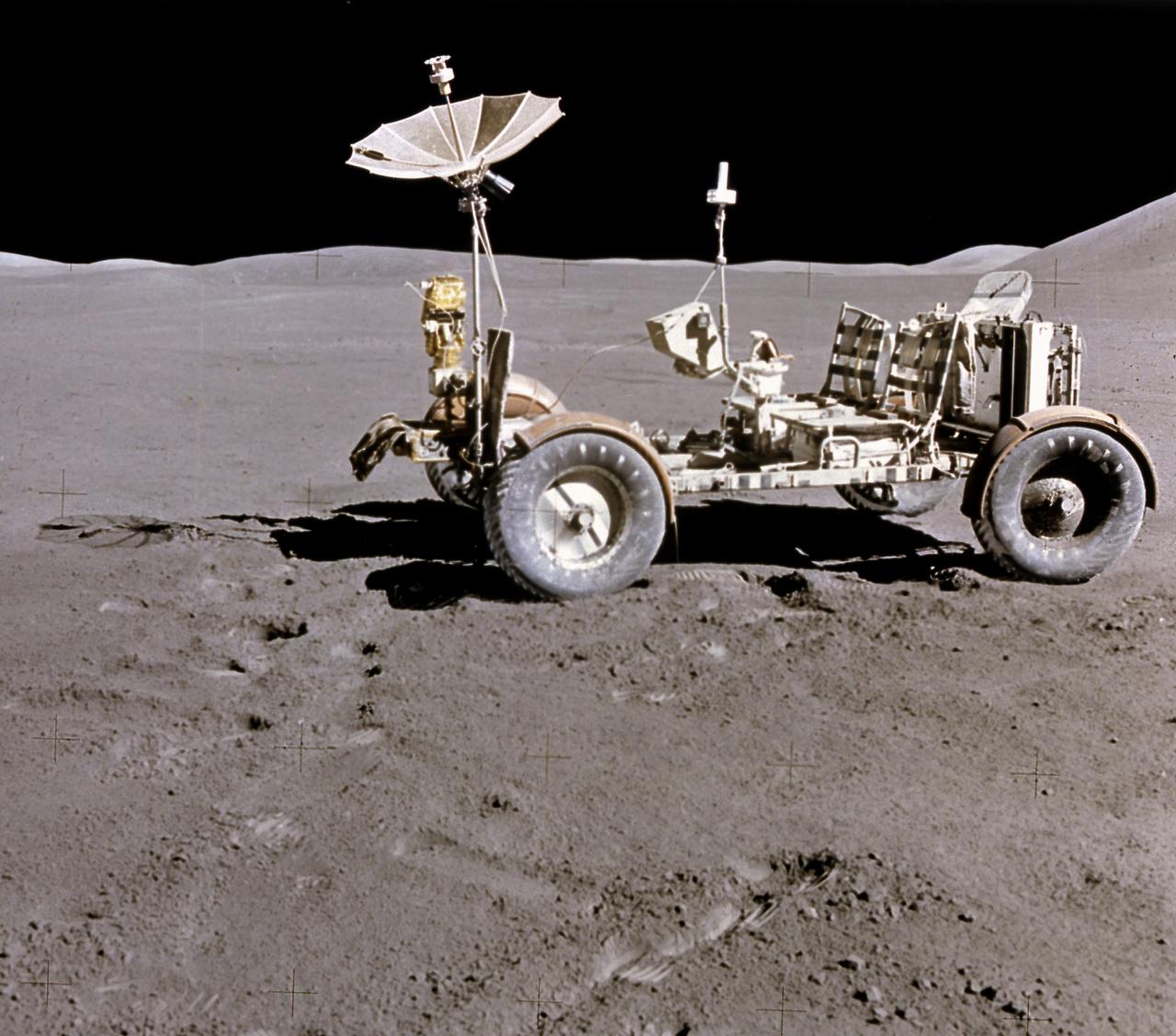
This photograph of the Lunar Roving Vehicle (LRV) was taken during the Apollo 15 mission. Powered by battery, the lightweight electric car greatly increased the range of mobility and productivity on the scientific traverses for astronauts. It weighed 462 pounds (77 pounds on the Moon) and could carry two suited astronauts, their gear and cameras, and several hundred pounds of bagged samples. The LRV's mobility was quite high. It could climb and descend slopes of about 25 degrees. The LRV was designed and developed by the Marshall Space Flight Center and built by the Boeing Company.
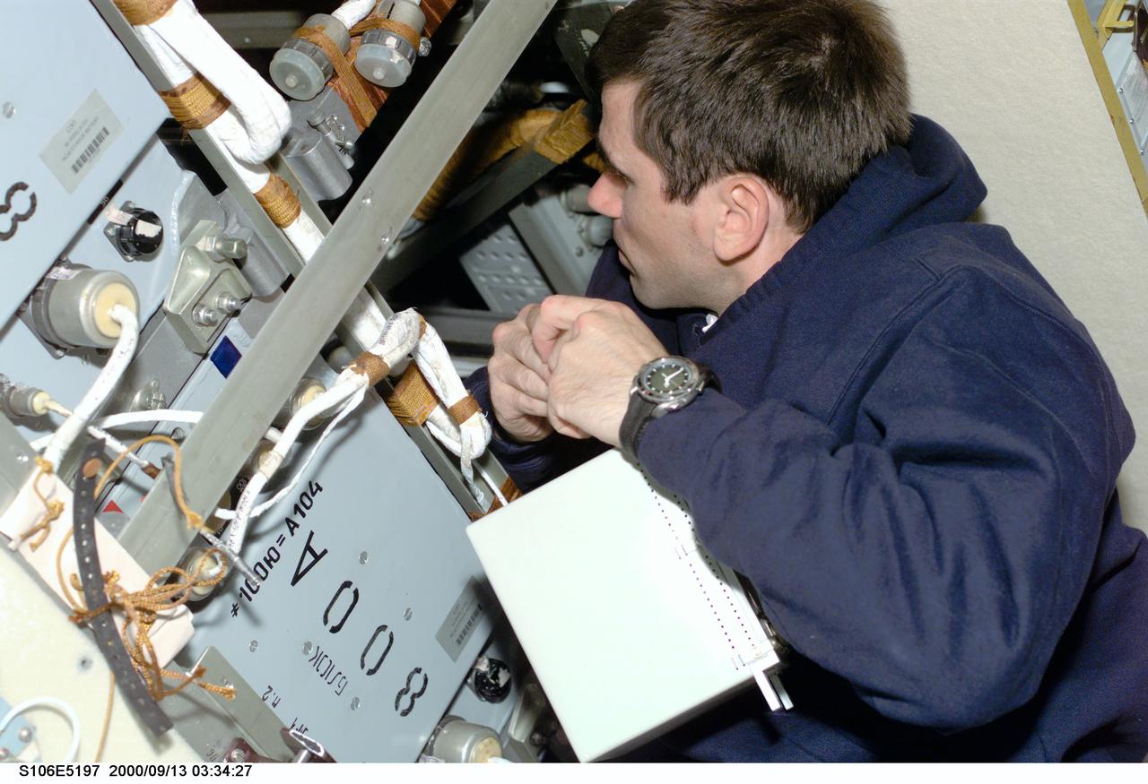
S106-E-5197 (13 September 2000) --- Cosmonaut Yuri I. Malenchenko, mission specialist representing the Russian Aviation and Space Agency, works aboard the Zvezda service module on the International Space Station (ISS). Electrical work was the hallmark of the day as four of the mission specialists aboard ISS (temporarily docked with the Space Shuttle Atlantis) replaced batteries inside the Zarya and Zvezda modules while supply transfer continued around them.
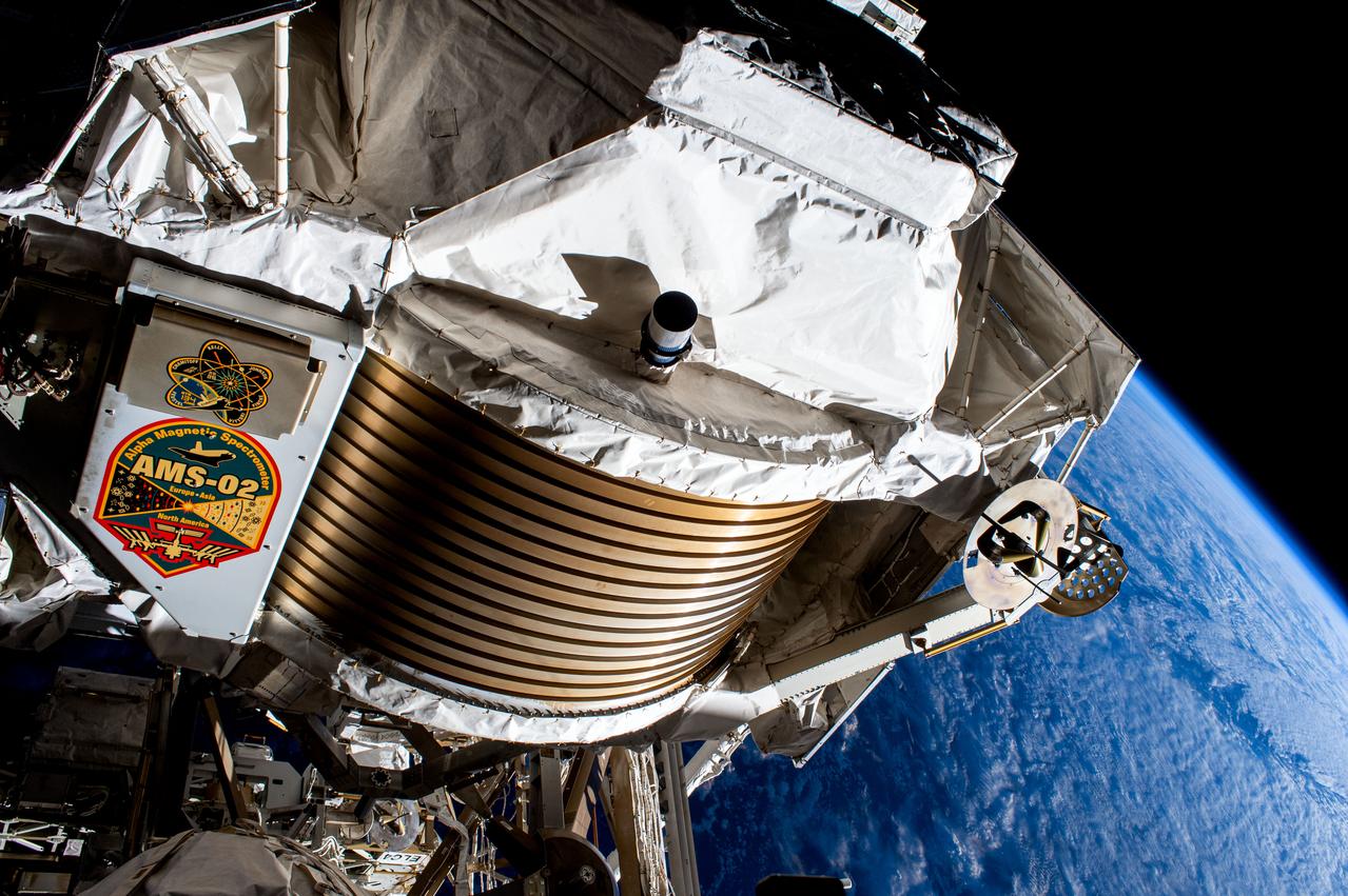
The Alpha Magnetic Spectrometer was photographed during a spacewalk in January 2017. NASA astronauts Shane Kimbrough and Peggy Whitson successfully installed three new adapter plates and hooked up electrical connections for three of the six new lithium-ion batteries on the International Space Station. They also accomplished several get-ahead tasks, including a photo survey of the Alpha Magnetic Spectrometer.

The Araxa mine in southern Brazil produces more than 80% of the world's Niobium. Niobium is used as an alloying agent in steels and in high-tech applications, such as electric car batteries. Brazil currently has 98% of commercial Niobium reserves in the world. The image was acquired November 5, 2023, covers an area of 16 by 17.1 km, and is located at 19.7 degrees south, 46.9 degrees west. https://photojournal.jpl.nasa.gov/catalog/PIA26395
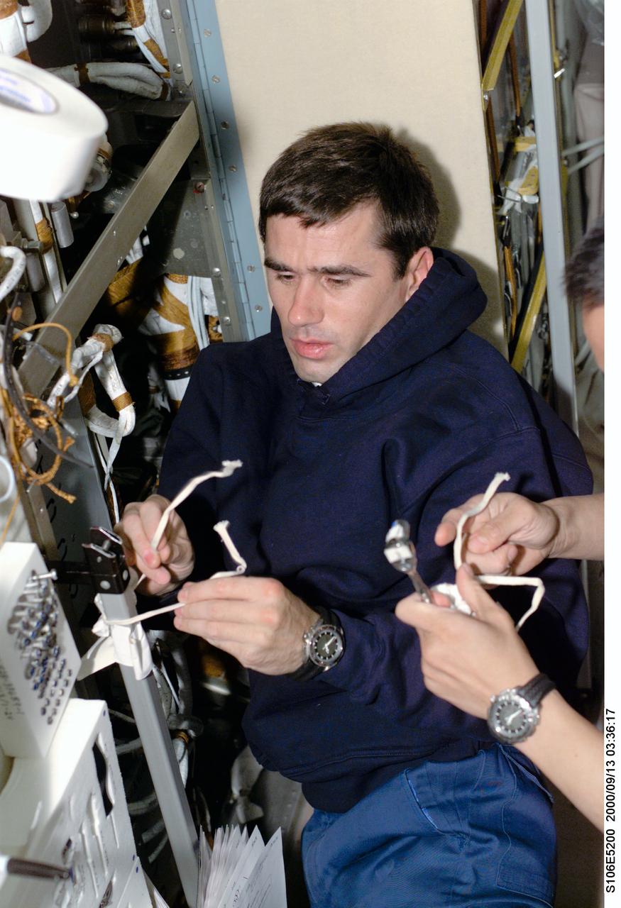
S106-E-5200 (13 September 2000) --- Cosmonaut Yuri I. Malenchenko, mission specialist representing the Russian Aviation and Space Agency, works aboard the Zvezda service module on the International Space Station (ISS). Electrical work was the hallmark of this day as four of the mission specialists aboard ISS (temporarily docked with the Space Shuttle Atlantis) replaced batteries inside the Zarya and Zvezda modules while supply transfer continued around them. Astronaut Edward T. Lu, mission specialist, is out of frame at right.
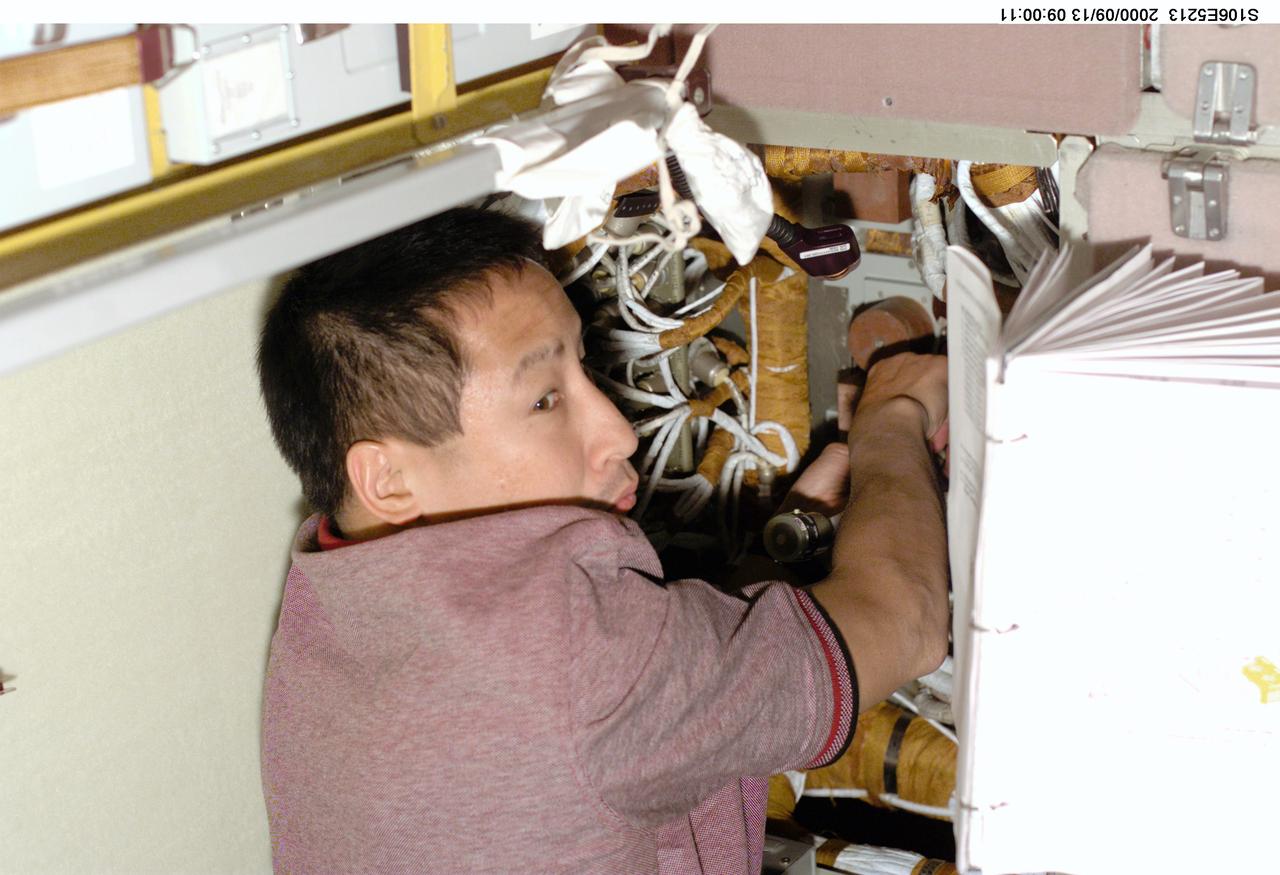
S106-E-5213 (13 September 2000) --- Astronaut Edward T. Lu follows printed guidelines as he assumes the role of an electrician onboard the Zvezda service module on the International Space Station (ISS). Electrical work was the hallmark of the day as four of the mission specialists aboard ISS (temporarily docked with the Space Shuttle Atlantis) replaced batteries inside the Zarya and Zvezda modules while supply transfer continued around them.
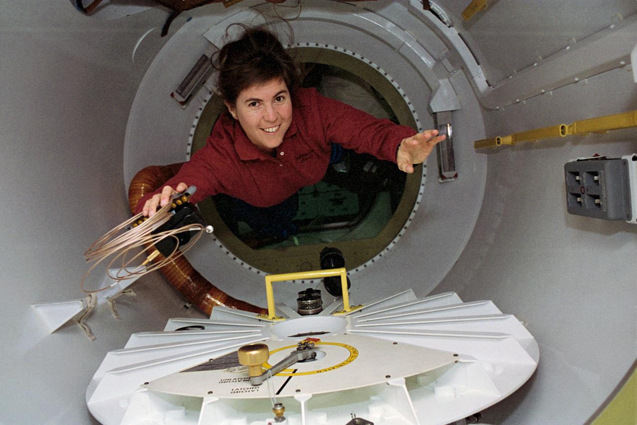
STS057-28-013 (21 June - 1 July 1993) --- With a camera and cable in hand, astronaut Janice E. Voss, mission specialist, floats through a special tunnel into the SpaceHab module. Voss and five other NASA astronauts spent almost ten days aboard the Space Shuttle Endeavour in Earth-orbit supporting the SpaceHab mission, retrieving the European Retrievable Carrier (EURECA) and conducting various experiments.
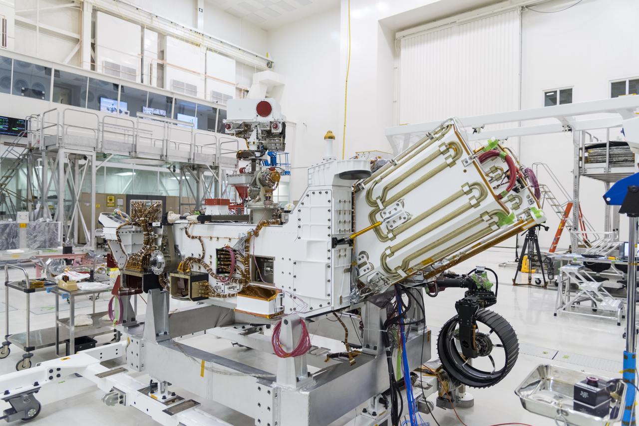
The electricity needed to operate NASA's Mars 2020 rover is provided by a power system called a Multi-Mission Radioisotope Thermoelectric Generator, or MMRTG. The MMRTG will be inserted into the aft end of the rover between the panels with gold tubing visible at the rear, which are called heat exchangers. Essentially a nuclear battery, an MMRTG uses the heat from the natural radioactive decay of plutonium-238 to generate about 110 watts of electricity at the start of a mission. Besides generating useful electrical power, the MMRTG produces heat. Some of this heat can be used to maintain the rover's systems at the proper operating temperatures in the frigid cold of space and on the surface of Mars. Some of it is rejected into space via the rover's Heat Rejection System. The gold-colored tubing on the heat exchangers form part of the cooling loops of that system. The tubes carry a fluid coolant called Trichlorofluoromethane (CFC-11) that helps dissipate the excess heat. The same tubes are used to pipe some of the heat back into the belly of the rover. MMRTGs are provided to NASA for civil space applications by the U.S. Department of Energy (DOE). The radioisotope fuel is inserted into the MMRTG at the DOE's Idaho National Laboratory before the MMRTG is shipped to the launch site. Electrically heated versions of the MMRTG are used at JPL to verify and practice integration of the power system with the rover. https://photojournal.jpl.nasa.gov/catalog/PIA23305
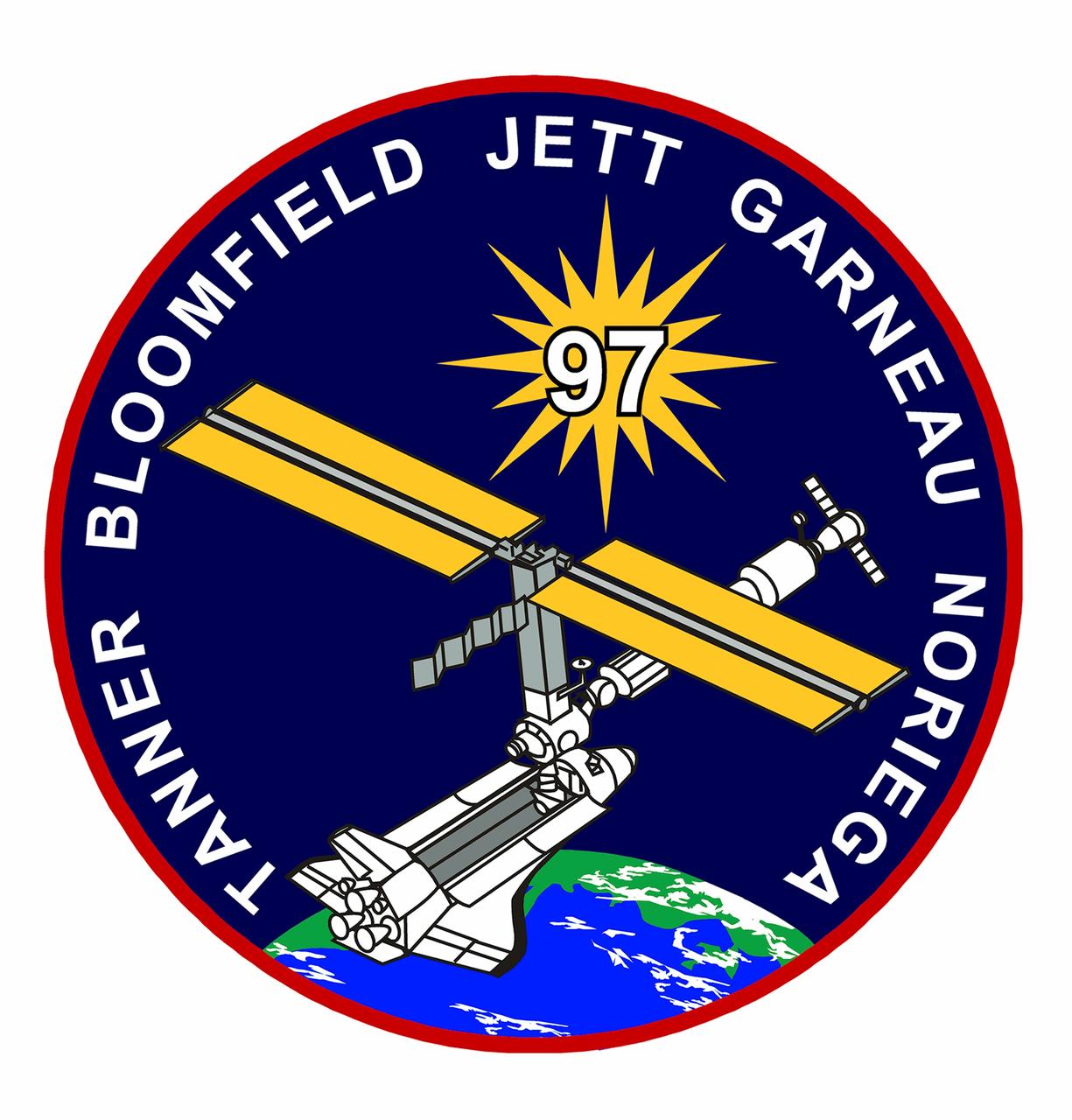
STS097-S-001 (January 2000) --- This is the crew insignia for STS-97, which will deliver, assemble, and activate the U.S. electrical power system on board the International Space Station (ISS). The electrical power system, which is built into a 47-foot integrated truss structure known as P6, consists of solar arrays, radiators, batteries, and electronics. P6 will be attached to the station using the shuttle's robotic arm in coordination with spacewalking crew members that will make the final connections. The spacewalkers will then prepare P6 for the subsequent deployments of the large solar arrays and radiator, which are critical steps in the activation of the electrical power system. The 120-foot solar arrays will provide the power necessary for the first ISS crews to live and work in the U.S. segment. The crew patch depicts the space shuttle docked to ISS in low Earth orbit after the activation of the P6 electrical power system. Gold and silver are used to highlight the portion of ISS that will be installed by the STS-97 crew. The Sun, central to the design, is the source of energy for ISS. The NASA insignia design for space shuttle flights is reserved for use by the astronauts and for other official use as the NASA Administrator may authorize. Public availability has been approved only in the forms of illustrations by the various news media. When and if there is any change in this policy, which is not anticipated, the change will be publicly announced. Photo credit: NASA

S115-E-06764 (17 Sept. 2006) --- This view of the International Space Station, backdropped against a blue and white Earth, was photographed shortly after the Space Shuttle Atlantis undocked from the orbital outpost at 7:50 a.m. (CDT). The unlinking completed six days, two hours and two minutes of joint operations with the station crew. Atlantis left the station with a new, second pair of 240-foot solar wings, attached to a new 17.5-ton section of truss with batteries, electronics and a giant rotating joint. The new solar arrays eventually will double the station's onboard power when their electrical systems are brought online during the next shuttle flight, planned for launch in December.
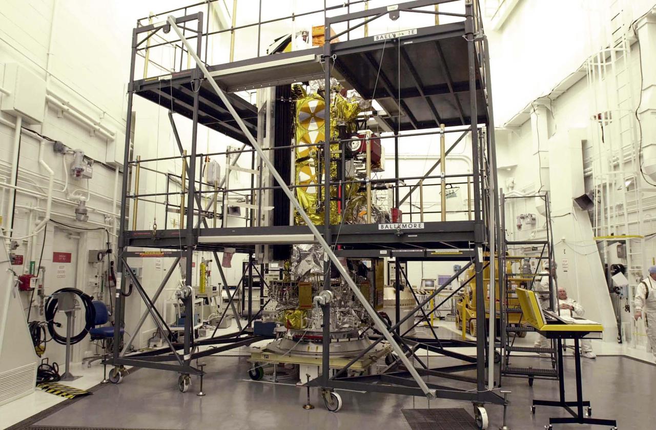
VANDENBERG AIR FORCE BASE, CALIF. - Inside the NASA spacecraft processing hangar 1610 located on North Vandenberg Air Force Base in California, the National Oceanic and Atmospheric Administration (NOAA-N) spacecraft is undergoing testing. The testing includes a the Spacecraft Electrical Performance Test, battery conditioning, a Solar Array Illumination Telemetry Test, final instrument inspections and closeouts for flight. Launch of NOAA-N aboard the Boeing Delta II rocket is currently scheduled for May 11, 2005. NOAA-N is the fourth in the series of support dedicated microwave instruments for the generation of temperature, moisture, surface, and hydrological products in cloudy regions where visible and infrared (IR) instruments have decreased capability.
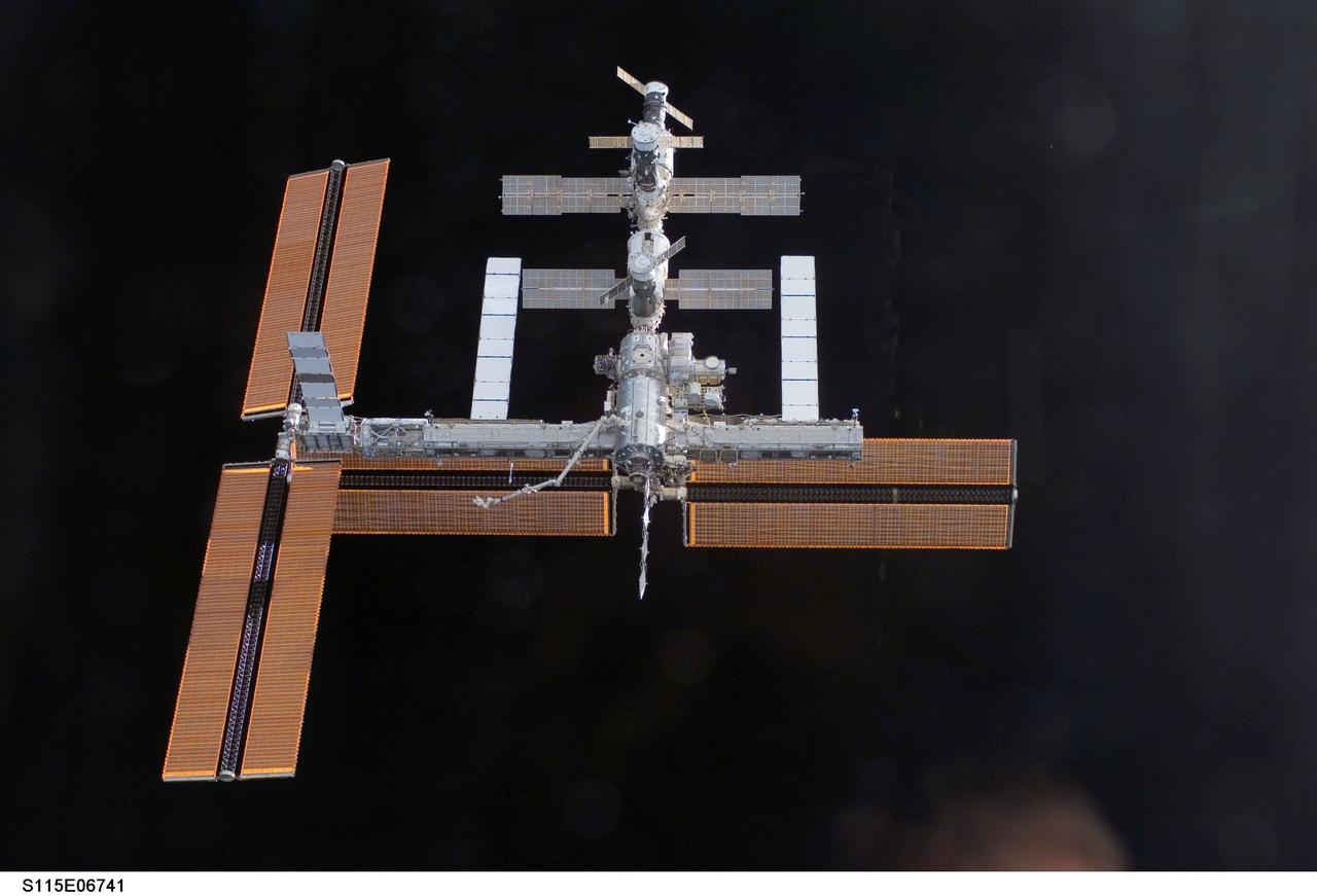
S115-E-06741 (17 Sept. 2006) --- This view of the International Space Station, backdropped against the blackness of space, was taken shortly after the Space Shuttle Atlantis undocked from the orbital outpost at 7:50 a.m. CDT. The unlinking completed six days, two hours and two minutes of joint operations with the station crew. Atlantis left the station with a new, second pair of 240-foot solar wings, attached to a new 17.5-ton section of truss with batteries, electronics and a giant rotating joint. The new solar arrays eventually will double the station's onboard power when their electrical systems are brought online during the next shuttle flight, planned for launch in December.
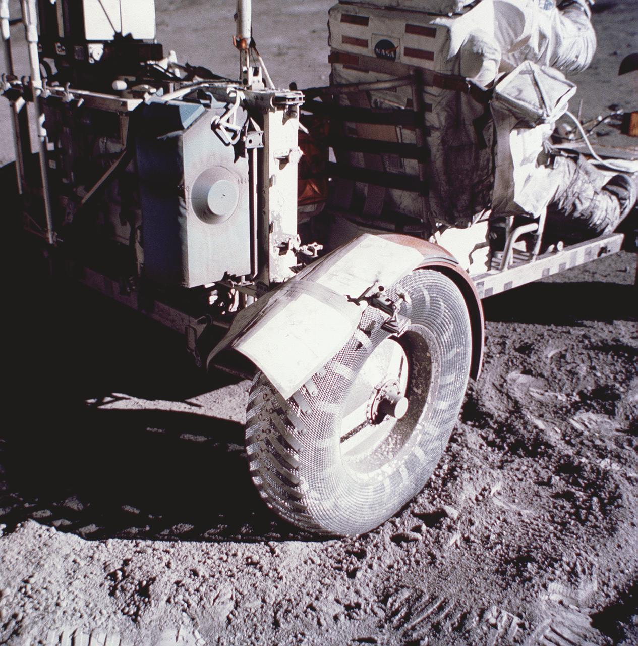
This photograph taken during the Apollo 17 mission (the last mission of the Apollo Program), depicts stiff plasticized maps being taped together and fastened by clamps to patch a broken fender of the Lunar Roving Vehicle (LRV). Powered by battery, the lightweight electric car greatly increased the range of mobility and productivity on the scientific traverses for astronauts. It weighed 462 pounds (77 pounds on the Moon) and could carry two suited astronauts, their gear and cameras, and several hundred pounds of bagged samples. The LRV's mobility was quite high. It could climb and descend slopes of about 25 degrees. The LRV was designed and developed by the Marshall Space Flight Center and built by the Boeing Company.
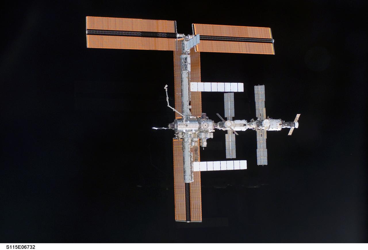
S115-E-06732 (17 Sept. 2006) --- This view of the International Space Station, backdropped against the blackness of space, was taken shortly after the Space Shuttle Atlantis undocked from the orbital outpost at 7:50 a.m. CDT. The unlinking completed six days, two hours and two minutes of joint operations with the station crew. Atlantis left the station with a new, second pair of 240-foot solar wings, attached to a new 17.5-ton section of truss with batteries, electronics and a giant rotating joint. The new solar arrays eventually will double the station's onboard power when their electrical systems are brought online during the next shuttle flight, planned for launch in December.
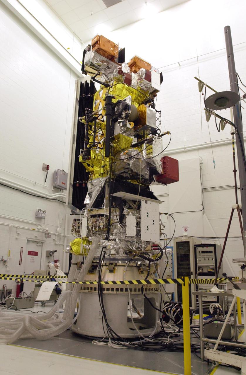
VANDENBERG AIR FORCE BASE, CALIF. - Inside the NASA spacecraft processing hangar 1610 located on North Vandenberg Air Force Base in California, the National Oceanic and Atmospheric Administration (NOAA-N) spacecraft is undergoing testing. The testing includes the Spacecraft Electrical Performance Test, battery conditioning, a Solar Array Illumination Telemetry Test, final instrument inspections and closeouts for flight. Launch of NOAA-N aboard the Boeing Delta II rocket is currently scheduled for May 11, 2005. NOAA-N is the fourth in the series of support dedicated microwave instruments for the generation of temperature, moisture, surface, and hydrological products in cloudy regions where visible and infrared (IR) instruments have decreased capability.

S115-E-06715 (17 Sept. 2006) --- This view of the International Space Station, backdropped against the blackness of space, was taken shortly after the Space Shuttle Atlantis undocked from the orbital outpost at 7:50 a.m. CDT. The unlinking completed six days, two hours and two minutes of joint operations with the station crew. Atlantis left the station with a new, second pair of 240-foot solar wings, attached to a new 17.5-ton section of truss with batteries, electronics and a giant rotating joint. The new solar arrays eventually will double the station's onboard power when their electrical systems are brought online during the next shuttle flight, planned for launch in December.
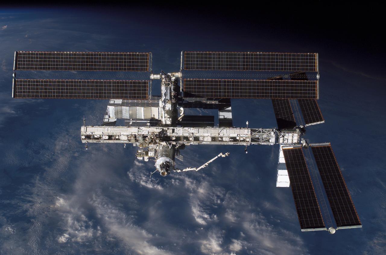
S115-E-06624 (17 Sept. 2006) --- This view of the International Space Station, backdropped against a cloud-covered Earth, was taken shortly after the Space Shuttle Atlantis undocked from the orbital outpost at 7:50 a.m. (CDT). The unlinking completed six days, two hours and two minutes of joint operations with the station crew. Atlantis left the station with a new, second pair of 240-foot solar wings, attached to a new 17.5-ton section of truss with batteries, electronics and a giant rotating joint. The new solar arrays eventually will double the station's onboard power when their electrical systems are brought online during the next shuttle flight, planned for launch in December.
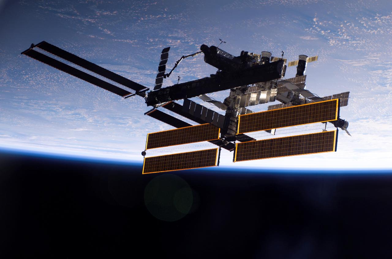
This view of the International Space Station, back dropped against the blackness of space and Earth, was taken shortly after the Space Shuttle Atlantis undocked from the orbital outpost at 7:50 a.m. CDT during the STS-115 mission. The unlinking completed after six days, two hours and two minutes of joint operations of the installation of the P3/P4 truss. The new 17 ton truss included batteries, electronics, a giant rotating joint, and sported a second pair of 240-foot solar wings. The new solar arrays will eventually double the onboard power of the Station when their electrical systems are brought online during the next shuttle flight, STS-116.

S115-E-06765 (17 Sept. 2006) --- This view of the International Space Station, backdropped against a blue and white Earth, was taken shortly after the Space Shuttle Atlantis undocked from the orbital outpost at 7:50 a.m. CDT. The unlinking completed six days, two hours and two minutes of joint operations with the station crew. Atlantis left the station with a new, second pair of 240-foot solar wings, attached to a new 17.5-ton section of truss with batteries, electronics and a giant rotating joint. The new solar arrays eventually will double the station's onboard power when their electrical systems are brought online during the next shuttle flight, planned for launch in December.
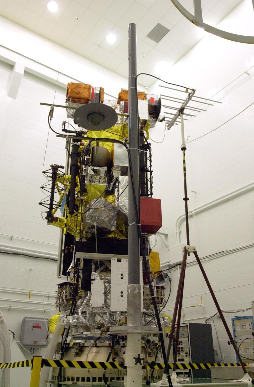
VANDENBERG AIR FORCE BASE, CALIF. - Inside the NASA spacecraft processing hangar 1610 located on North Vandenberg Air Force Base in California, the National Oceanic and Atmospheric Administration (NOAA-N) spacecraft is undergoing testing. The testing includes the Spacecraft Electrical Performance Test, battery conditioning, a Solar Array Illumination Telemetry Test, final instrument inspections and closeouts for flight. Launch of NOAA-N aboard the Boeing Delta II rocket is currently scheduled for May 11, 2005. NOAA-N is the fourth in the series of support dedicated microwave instruments for the generation of temperature, moisture, surface, and hydrological products in cloudy regions where visible and infrared (IR) instruments have decreased capability.
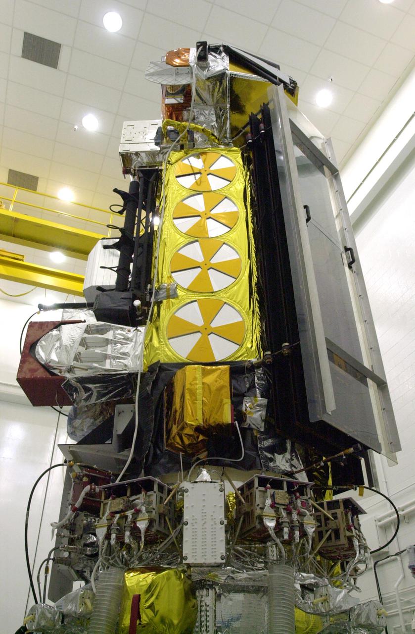
VANDENBERG AIR FORCE BASE, CALIF. - Inside the NASA spacecraft processing hangar 1610 located on North Vandenberg Air Force Base in California, the National Oceanic and Atmospheric Administration (NOAA-N) spacecraft is undergoing testing. The testing includes a Spacecraft Electrical Performance Test, battery conditioning, a Solar Array Illumination Telemetry Test, final instrument inspections and closeouts for flight. Launch of NOAA-N aboard the Boeing Delta II rocket is currently scheduled for May 11, 2005. NOAA-N is the fourth in the series of support dedicated microwave instruments for the generation of temperature, moisture, surface, and hydrological products in cloudy regions where visible and infrared (IR) instruments have decreased capability.
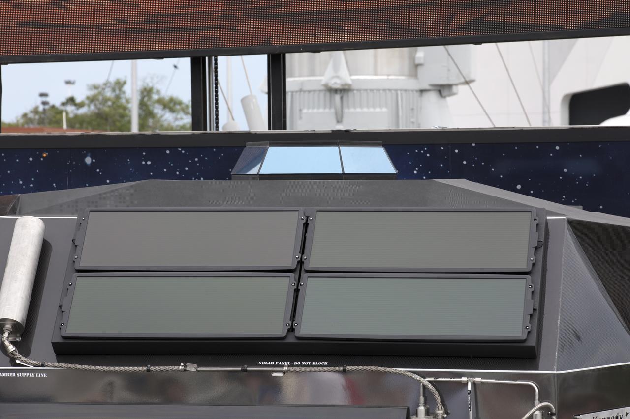
The scientifically-themed Mars rover concept vehicle operates on an electric motor, powered by solar panels and a 700-volt battery. The back section opens and serves as a laboratory which can disconnect for autonomous research. While this exact rover is not expected to operate on Mars, one or more of its elements could make its way into a rover astronauts will drive on the Red Planet. The "Summer of Mars" promotion is designed to provide guests with a better understanding of NASA's studies of the Red Planet. The builders of the rover, Parker Brothers Concepts of Port Canaveral, Florida, incorporated input into its design from NASA subject matter experts.
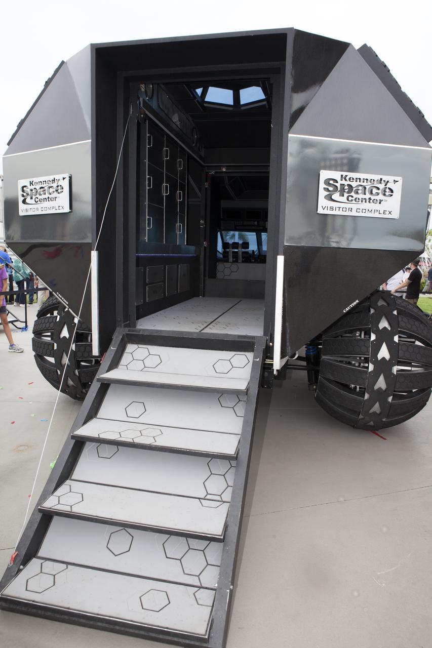
The scientifically-themed Mars rover concept vehicle operates on an electric motor, powered by solar panels and a 700-volt battery. The back section opens and serves as a laboratory which can disconnect for autonomous research. While this exact rover is not expected to operate on Mars, one or more of its elements could make its way into a rover astronauts will drive on the Red Planet. The "Summer of Mars" promotion is designed to provide guests with a better understanding of NASA's studies of the Red Planet. The builders of the rover, Parker Brothers Concepts of Port Canaveral, Florida, incorporated input into its design from NASA subject matter experts.
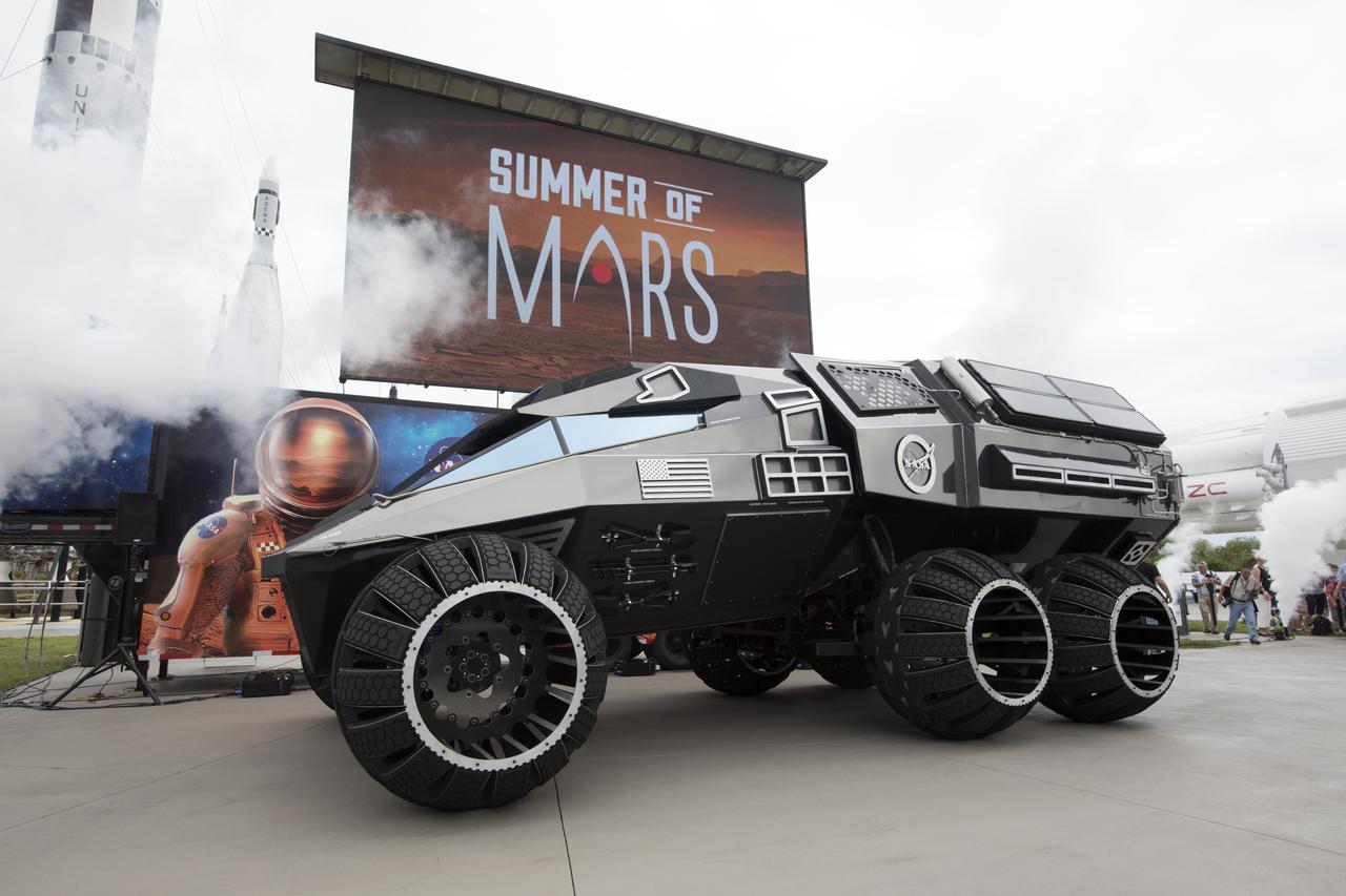
The scientifically-themed Mars rover concept vehicle operates on an electric motor, powered by solar panels and a 700-volt battery. The rover separates in the middle with the front area designed for scouting and equipped with a radio and navigation provided by the Global Positioning System. The back section serves as a full laboratory which can disconnect for autonomous research. The "Summer of Mars" promotion is designed to provide guests with a better understanding of NASA's studies of the Red Planet. The builders of the rover, Parker Brothers Concepts of Port Canaveral, Florida, incorporated input into its design from NASA subject matter experts.
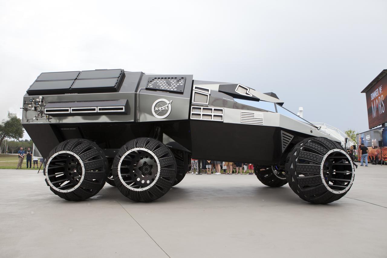
The scientifically-themed Mars rover concept vehicle operates on an electric motor, powered by solar panels and a 700-volt battery. The rover separates in the middle with the front area designed for scouting and equipped with a radio and navigation provided by the Global Positioning System. The back section serves as a full laboratory which can disconnect for autonomous research. The "Summer of Mars" promotion is designed to provide guests with a better understanding of NASA's studies of the Red Planet. The builders of the rover, Parker Brothers Concepts of Port Canaveral, Florida, incorporated input into its design from NASA subject matter experts.
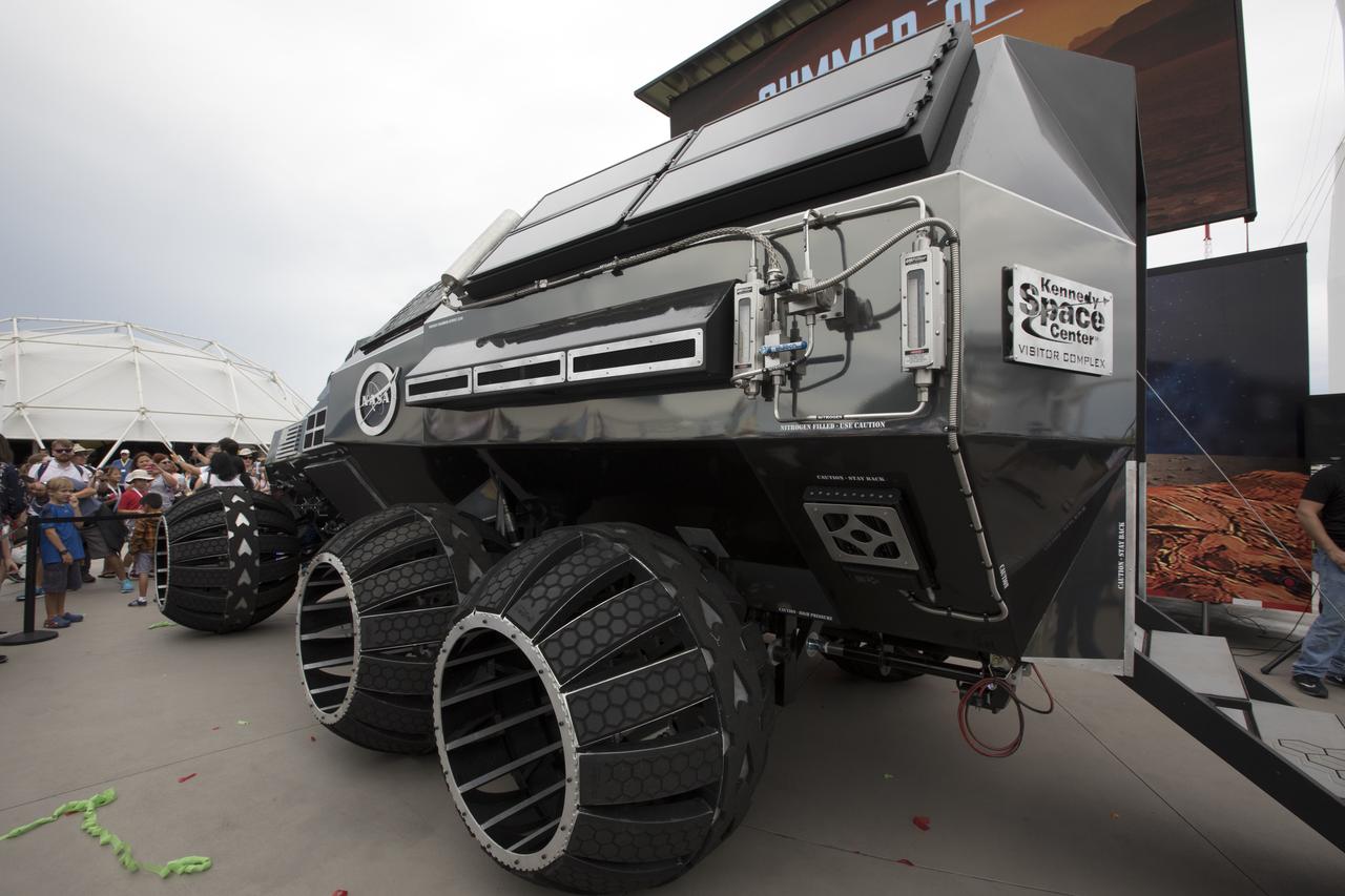
The scientifically-themed Mars rover concept vehicle operates on an electric motor, powered by solar panels and a 700-volt battery. The back section opens and serves as a laboratory which can disconnect for autonomous research. While this exact rover is not expected to operate on Mars, one or more of its elements could make its way into a rover astronauts will drive on the Red Planet. The "Summer of Mars" promotion is designed to provide guests with a better understanding of NASA's studies of the Red Planet. The builders of the rover, Parker Brothers Concepts of Port Canaveral, Florida, incorporated input into its design from NASA subject matter experts.

S115-E-06723 (17 Sept. 2006) --- This view of the International Space Station, backdropped against the blackness of space, was taken shortly after the Space Shuttle Atlantis undocked from the orbital outpost at 7:50 a.m. CDT. The unlinking completed six days, two hours and two minutes of joint operations with the station crew. Atlantis left the station with a new, second pair of 240-foot solar wings, attached to a new 17.5-ton section of truss with batteries, electronics and a giant rotating joint. The new solar arrays eventually will double the station's onboard power when their electrical systems are brought online during the next shuttle flight, planned for launch in December.

S115-E-06707 (17 Sept. 2006) --- This view of the International Space Station, backdropped against the blackness of space, was taken shortly after the Space Shuttle Atlantis undocked from the orbital outpost at 7:50 a.m. CDT. The unlinking completed six days, two hours and two minutes of joint operations with the station crew. Atlantis left the station with a new, second pair of 240-foot solar wings, attached to a new 17.5-ton section of truss with batteries, electronics and a giant rotating joint. The new solar arrays eventually will double the station's onboard power when their electrical systems are brought online during the next shuttle flight, planned for launch in December.
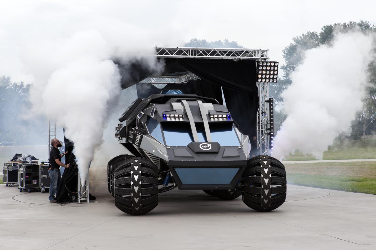
The scientifically-themed Mars rover concept vehicle operates on an electric motor, powered by solar panels and a 700-volt battery. The rover separates in the middle with the front area designed for scouting and equipped with a radio and navigation provided by the Global Positioning System. The back section serves as a full laboratory which can disconnect for autonomous research. The "Summer of Mars" promotion is designed to provide guests with a better understanding of NASA's studies of the Red Planet. The builders of the rover, Parker Brothers Concepts of Port Canaveral, Florida, incorporated input into its design from NASA subject matter experts.
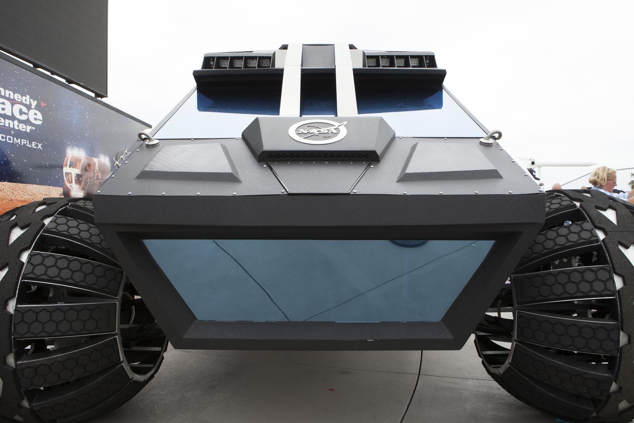
The scientifically-themed Mars rover concept vehicle operates on an electric motor, powered by solar panels and a 700-volt battery. The back section opens and serves as a laboratory which can disconnect for autonomous research. While this exact rover is not expected to operate on Mars, one or more of its elements could make its way into a rover astronauts will drive on the Red Planet. The "Summer of Mars" promotion is designed to provide guests with a better understanding of NASA's studies of the Red Planet. The builders of the rover, Parker Brothers Concepts of Port Canaveral, Florida, incorporated input into its design from NASA subject matter experts.
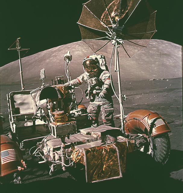
This is an Apollo 17 onboard photo of an astronaut beside the Lunar Roving Vehicle (LRV) on the lunar surface. Designed and developed by the Marshall Space Flight Center and built by the Boeing Company, the LRV was first used on the Apollo 15 mission and increased the range of astronauts' mobility and productivity on the lunar surface. This lightweight electric car had battery power sufficient for about 55 miles. It weighed 462 pounds (77 pounds on the Moon) and could carry two suited astronauts, their gear, cameras, and several hundred pounds of bagged samples. The LRV's mobility was quite high. It could climb and descend slopes of about 25 degrees.

S115-E-06750 (17 Sept. 2006) --- This view of the International Space Station, backdropped against the blackness of space, was taken shortly after the Space Shuttle Atlantis undocked from the orbital outpost at 7:50 a.m. (CDT). The unlinking completed six days, two hours and two minutes of joint operations with the station crew. Atlantis left the station with a new, second pair of 240-foot solar wings, attached to a new 17.5-ton section of truss with batteries, electronics and a giant rotating joint. The new solar arrays eventually will double the station's onboard power when their electrical systems are brought online during the next shuttle flight, planned for launch in December.
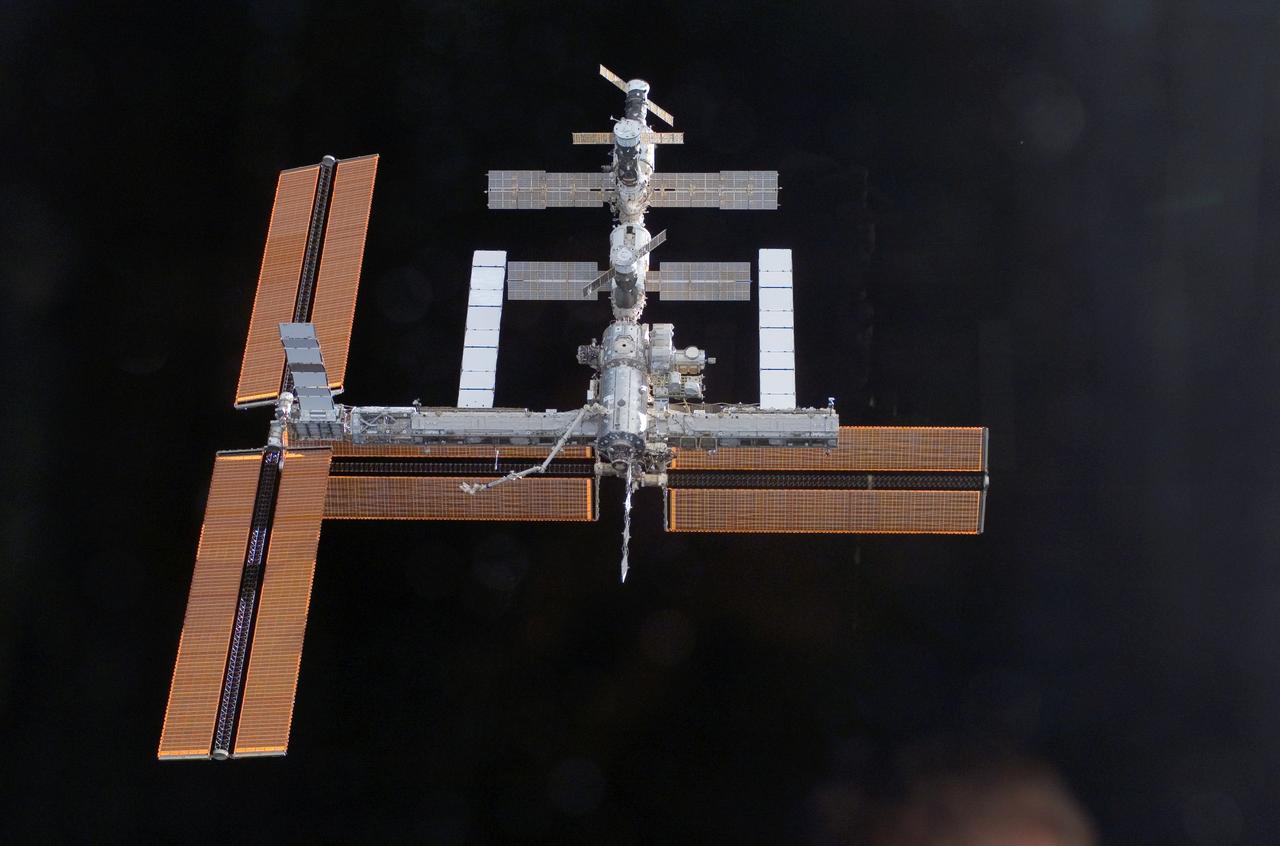
This view of the International Space Station, back dropped against the blackness of space, was taken shortly after the Space Shuttle Atlantis undocked from the orbital outpost at 7:50 a.m. CDT during the STS-115 mission. The unlinking completed after six days, two hours and two minutes of joint operations of the installation of the P3/P4 truss. The new 17 ton truss included batteries, electronics, a giant rotating joint, and sported a second pair of 240-foot solar wings. The new solar arrays will eventually double the onboard power of the Station when their electrical systems are brought online during the next shuttle flight, STS-116.

S115-E-06767 (17 Sept. 2006) --- This view of the International Space Station, backdropped against a blue and white Earth, was taken shortly after the Space Shuttle Atlantis undocked from the orbital outpost at 7:50 a.m. (CDT). The unlinking completed six days, two hours and two minutes of joint operations with the station crew. Atlantis left the station with a new, second pair of 240-foot solar wings, attached to a new 17.5-ton section of truss with batteries, electronics and a giant rotating joint. The new solar arrays eventually will double the station's onboard power when their electrical systems are brought online during the next shuttle flight, planned for launch in December.
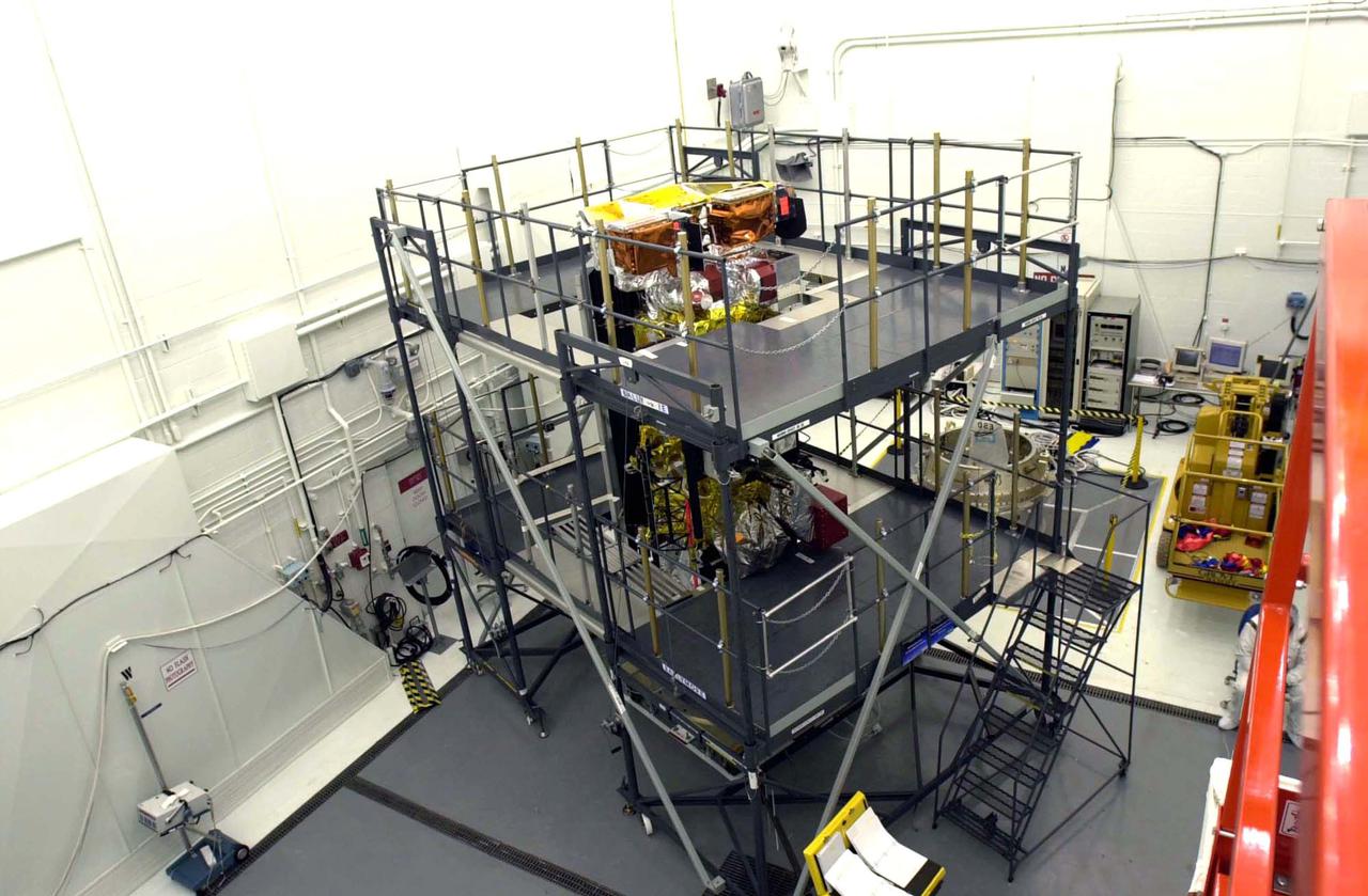
VANDENBERG AIR FORCE BASE, CALIF. - Inside the NASA spacecraft processing hangar 1610 located on North Vandenberg Air Force Base in California, the National Oceanic and Atmospheric Administration (NOAA-N) spacecraft is undergoing testing. The testing includes a the Spacecraft Electrical Performance Test, battery conditioning, a Solar Array Illumination Telemetry Test, final instrument inspections and closeouts for flight. Launch of NOAA-N aboard the Boeing Delta II rocket is currently scheduled for May 11, 2005. NOAA-N is the fourth in the series of support dedicated microwave instruments for the generation of temperature, moisture, surface, and hydrological products in cloudy regions where visible and infrared (IR) instruments have decreased capability.

S115-E-06759 (17 Sept. 2006) --- This view of the International Space Station over a blue and white Earth was taken shortly after the Space Shuttle Atlantis undocked from the orbital outpost at 7:50 a.m. CDT. The unlinking completed six days, two hours and two minutes of joint operations with the station crew. Atlantis left the station with a new, second pair of 240-foot solar wings, attached to a new 17.5-ton section of truss with batteries, electronics and a giant rotating joint. The new solar arrays eventually will double the station's onboard power when their electrical systems are brought online during the next shuttle flight, planned for launch in December.
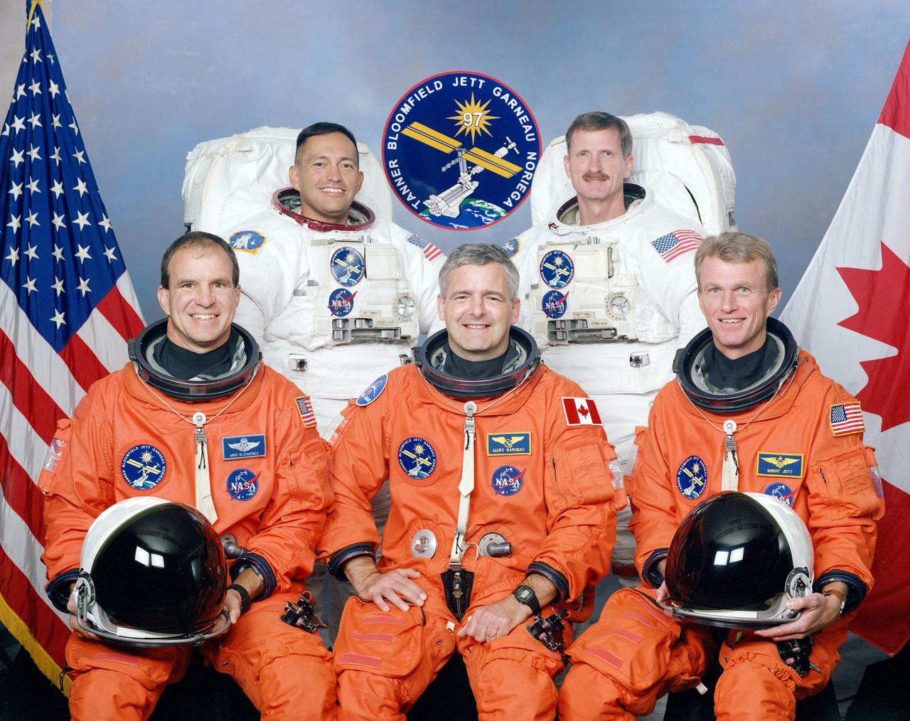
These five STS-97 crew members posed for a traditional portrait during training. On the front row, left to right, are astronauts Michael J. Bloomfield, pilot; Marc Garneau, mission specialist representing the Canadian Space Agency (CSA); and Brent W. Jett, Jr., commander. In the rear, wearing training versions of the extravehicular mobility unit (EMU) space suits, (left to right) are astronauts Carlos I. Noriega, and Joseph R. Tarner, both mission specialists. The primary objective of the STS-97 mission was the delivery, assembly, and activation of the U.S. electrical power system onboard the International Space Station (ISS). The electrical power system, which is built into a 73-meter (240-foot) long solar array structure consists of solar arrays, radiators, batteries, and electronics. The entire 15.4-metric ton (17-ton) package is called the P6 Integrated Truss Segment and is the heaviest and largest element yet delivered to the station aboard a space shuttle. The electrical system will eventually provide the power necessary for the first ISS crews to live and work in the U.S. segment. The STS-97 crew of five launched aboard the Space Shuttle Orbiter Endeavor on November 30, 2000 for an 11 day mission.
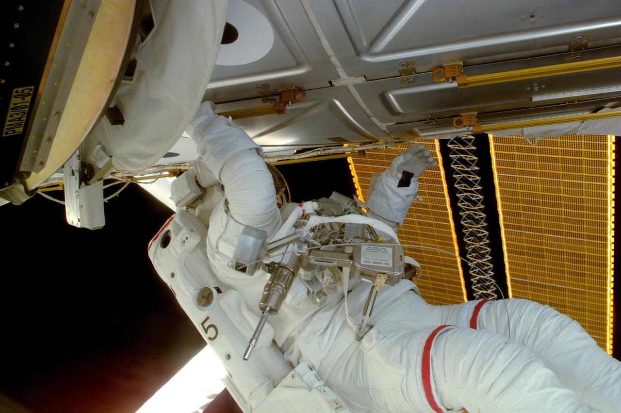
Astronaut Joseph R. Tanner, STS-97 mission specialist, is seen during a session of Extravehicular Activity (EVA), performing work on the International Space Station (ISS). Part of the Remote Manipulator System (RMS) arm and a section of the newly deployed solar array panel are in the background. The primary objective of the STS-97 mission was the delivery, assembly, and activation of the U.S. electrical power system on board the ISS. The electrical power system, which is built into a 73-meter (240-foot) long solar array structure consists of solar arrays, radiators, batteries, and electronics. The entire 15.4-metric ton (17-ton) package is called the P6 Integrated Truss Segment and is the heaviest and largest element yet delivered to the station aboard a space shuttle. The electrical system will eventually provide the power necessary for the first ISS crews to live and work in the U.S. segment. The STS-97 crew of five launched aboard the Space Shuttle Orbiter Endeavor on November 30, 2000 for an 11 day mission.
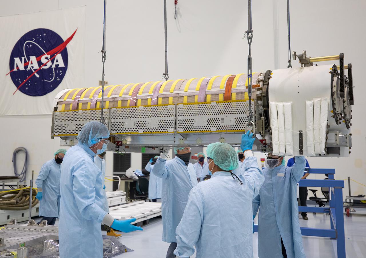
NASA and Boeing workers lift solar arrays into flight support equipment on April 2, 2021, in the Space Station Processing Facility at NASA’s Kennedy Space Center in Florida. The 63- by- 20-foot solar arrays will launch to the International Space Station later this year. They are the first two of six new solar arrays that in total will produce more than 120 kilowatts of electricity from the Sun’s energy, enough to power more than 40 average U.S. homes. Combined with the eight original, larger arrays, this advanced hardware will provide 215 kilowatts of energy, a 20 to 30 percent increase in power, helping maximize the space station’s capabilities for years to come. The arrays will produce electricity to sustain the station’s systems and equipment, plus augment the electricity available to continue a wide variety of public and private experiments and research in the microgravity environment of low-Earth orbit. Most of the station systems, including its batteries, scientific equipment racks, and communications equipment have been upgraded since humans began a continuous presence on the orbiting laboratory in November 2000. For more than two decades, astronauts have lived and worked on this unique orbiting lab, supporting scientific research that has led to numerous discoveries that benefit people on Earth and prepare for future Artemis missions to the Moon and beyond.
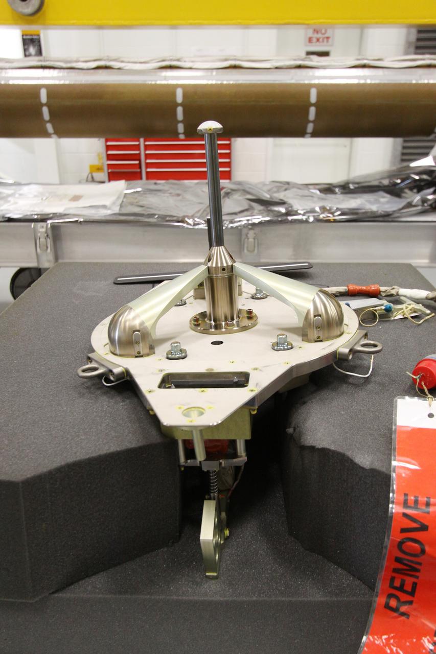
CAPE CANAVERAL, Fla. - In the Remote Manipulator System Lab inside the Vehicle Assembly Building at NASA's Kennedy Space Center in Florida, this close-up shows the electrical flight grapple fixture which will be installed in the forward transition and X-guide restraint of the inspection boom assembly, or IBA, on space shuttle Atlantis' orbiter boom sensor system, or OBSS. The IBA is removed from the shuttle every other processing flow for a detailed inspection. After five consecutive flights, all IBA internal components are submitted to a thorough electrical checkout in the lab. The 50-foot-long OBSS attaches to the end of the shuttle’s robotic arm and supports the cameras and laser systems used to inspect the shuttle’s thermal protection system while in space. Atlantis is next slated to deliver an Integrated Cargo Carrier and Russian-built Mini Research Module to the International Space Station on the STS-132 mission. The second in a series of new pressurized components for Russia, the module will be permanently attached to the Zarya module. Three spacewalks are planned to store spare components outside the station, including six spare batteries, a boom assembly for the Ku-band antenna and spares for the Canadian Dextre robotic arm extension. A radiator, airlock and European robotic arm for the Russian Multi-purpose Laboratory Module also are payloads on the flight. Launch is targeted for May 14, 2010. Photo credit: NASA/Jack Pfaller
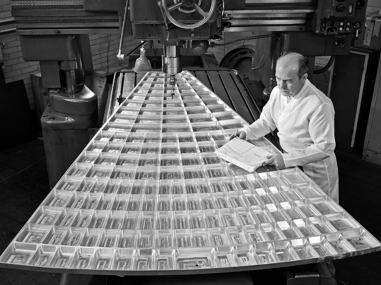
Daniel Bernatowicz, Chief of the Advanced Power Systems Branch at the National Aeronautics and Space Administration (NASA) Lewis Research Center, examines a 20-foot section of a solar mirror being fabricated in the Jig Bore Room of the Technical Services Building. NASA Lewis was conducting a wide-ranging effort to explore methods of generating electrical power for spacecraft. One method employed a large parabolic mirror to concentrate the sun’s energy. The mirror had to remain rigid and withstand micrometeoroids, but remain light and compact enough to be easily launched. In 1963 Bernatowicz and his researchers undertook a program to design a solar mirror to work with the Brayton cycle system on a space station. The mirror in this photograph was prepared for a conference on Advanced Technology in Space Power Systems held at Lewis in late August 1966. Lewis experts discussed advances with batteries, fuel cells, isotope and thermoelectric generators, and the SNAP-8 space power system. Lewis was developing several types of solar mirrors to work with a Brayton cycle electric generating system. The mirror’s 12 sections were shaped using a unique forming process developed at Lewis, coated with an epoxy, and plated with aluminum. The mirror concentrated the Sun's rays on a heat storage receiver containing lithium fluoride. This material was heated to produce power in a turbogenerator system, while additional heat was stored for use when the unit was in the Earth's shadow.
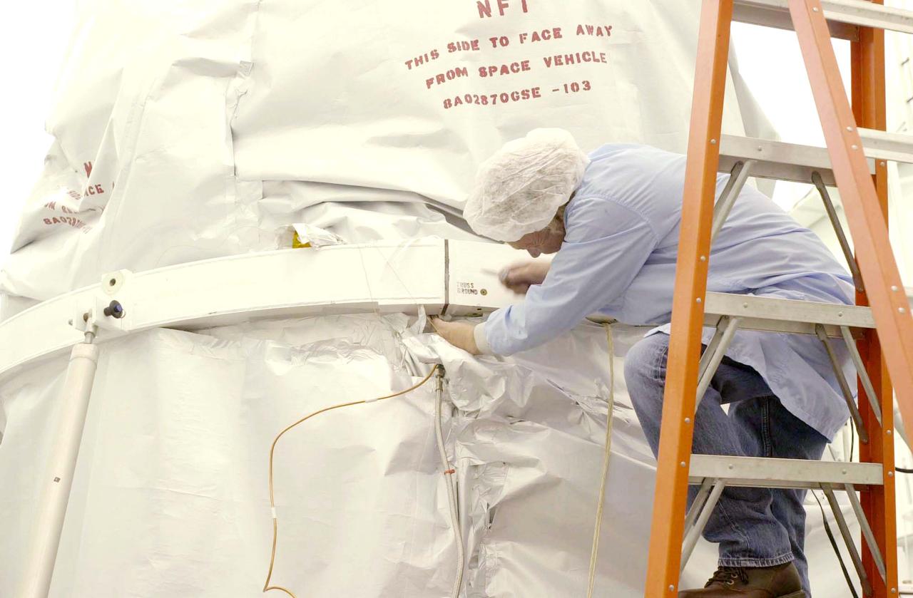
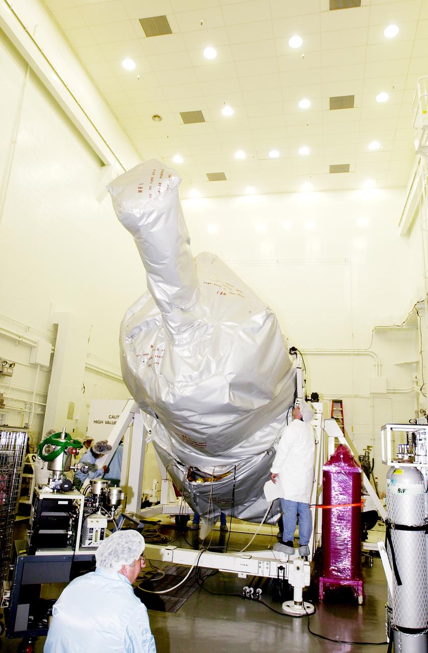
In the spacecraft processing facility on North Vandenberg Air Force Base, workers prepare to remove the soft shipping cover from the Gravity Probe B experiment. Immediate processing includes setting up mechanical and electrical ground support equipment, making necessary connections and conditioning the spacecraft battery. The Gravity Probe B will launch a payload of four gyroscopes into low-Earth polar orbit to test two extraordinary predictions of Albert Einstein’s general theory of relativity: the geodetic effect (how space and time are warped by the presence of the Earth) and frame dragging (how Earth’s rotation drags space and time around with it). Once in orbit, for 18 months each gyroscope’s spin axis will be monitored as it travels through local spacetime, observing and measuring these effects. The experiment was developed by Stanford University, Lockheed Martin and NASA’s Marshall Space Flight Center.
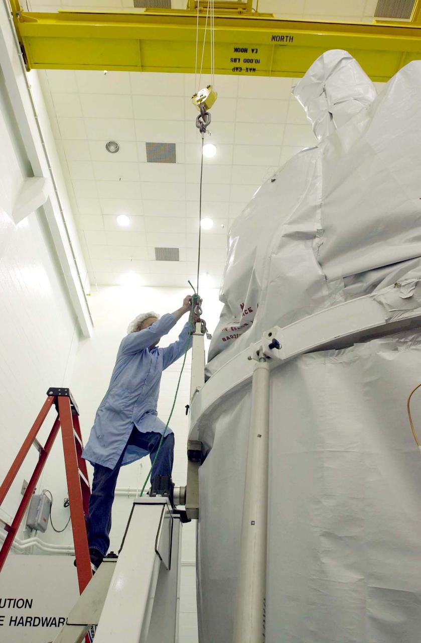
In the spacecraft processing facility on North Vandenberg Air Force Base, workers prepare to remove the soft shipping cover from the Gravity Probe B experiment. Immediate processing includes setting up mechanical and electrical ground support equipment, making necessary connections and conditioning the spacecraft battery. The Gravity Probe B will launch a payload of four gyroscopes into low-Earth polar orbit to test two extraordinary predictions of Albert Einstein’s general theory of relativity: the geodetic effect (how space and time are warped by the presence of the Earth) and frame dragging (how Earth’s rotation drags space and time around with it). Once in orbit, for 18 months each gyroscope’s spin axis will be monitored as it travels through local spacetime, observing and measuring these effects. The experiment was developed by Stanford University, Lockheed Martin and NASA’s Marshall Space Flight Center.
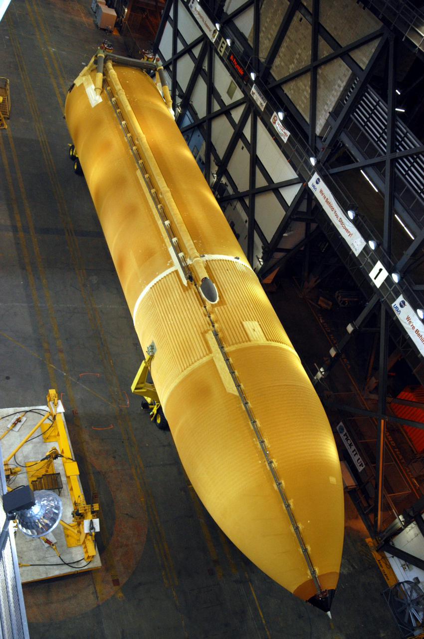
KENNEDY SPACE CENTER, FLA. - Inside the Vehicle Assembly Building, the redesigned External Tank to be used on Return to Flight mission STS-114 waits in the transfer aisle after its move from the barge in the Launch Complex 39 Area Turn Basin. The tank will be raised from a horizontal to a vertical position, then lifted high up into a storage cell, or “checkout cell,” where it will undergo inspections of the mechanical, electrical and thermal protection systems. New processing activities resulting from redesign of the tank include inspection of the bipod heater and External Tank separation camera, which includes charging the camera batteries. The tank will be then prepared for mating to the Solid Rocket Boosters. When preparations are complete, the tank will be lifted from the checkout cell, moved across the transfer aisle and into High Bay 1, where it will be lowered and attached to the boosters, which are sitting on the Mobile Launch Platform.
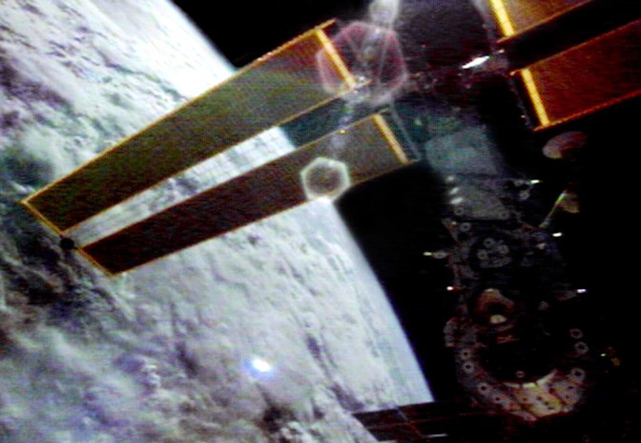
This video still depicts the recently deployed starboard and port solar arrays towering over the International Space Station (ISS). The video was recorded on STS-97's 65th orbit. Delivery, assembly, and activation of the solar arrays was the main mission objective of STS-97. The electrical power system, which is built into a 73-meter (240-foot) long solar array structure consists of solar arrays, radiators, batteries, and electronics, and will provide the power necessary for the first ISS crews to live and work in the U.S. segment. The entire 15.4-metric ton (17-ton) package is called the P6 Integrated Truss Segment, and is the heaviest and largest element yet delivered to the station aboard a space shuttle. The STS-97 crew of five launched aboard the Space Shuttle Orbiter Endeavor on November 30, 2000 for an 11 day mission.
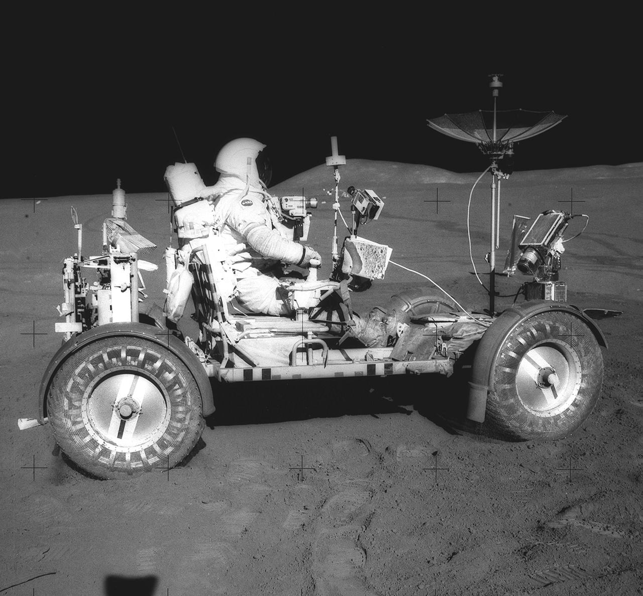
This photograph was taken during the Apollo 15 mission on the lunar surface. Astronaut David R. Scott waits in the Lunar Roving Vehicle (LRV) for astronaut James Irwin for the return trip to the Lunar Module, Falcon, with rocks and soil collected near the Hadley-Apernine landing site. The Apollo 15 was the first mission to use the LRV. Powered by battery, the lightweight electric car greatly increased the range of mobility and productivity on the scientific traverses for astronauts. It weighed 462 pounds (77 pounds on the Moon) and could carry two suited astronauts, their gear and cameras, and several hundred pounds of bagged samples. The LRV's mobility was quite high. It could climb and descend slopes of about 25 degrees. The LRV was designed and developed by the Marshall Space Flight Center and built by the Boeing Company.
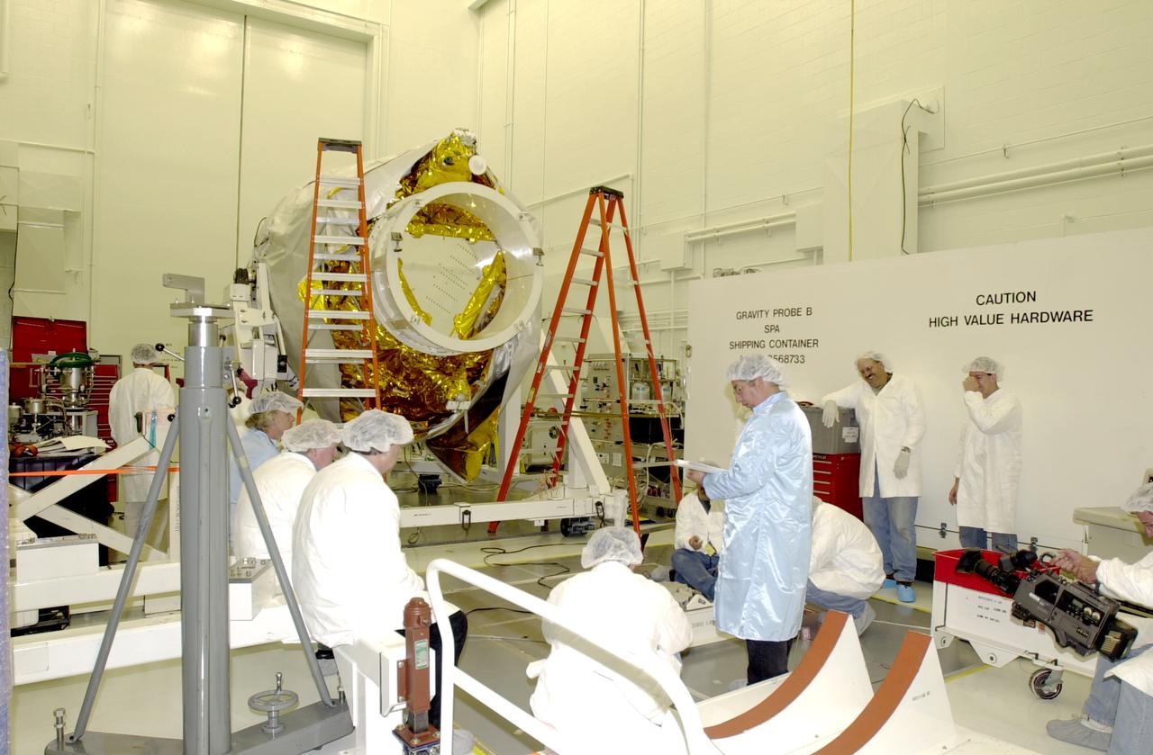
Workers in the spacecraft processing facility on North Vandenberg Air Force Base get ready to begin processing the Gravity Probe B experiment, including setting up mechanical and electrical ground support equipment, making necessary connections and conditioning the spacecraft battery. The Gravity Probe B will launch a payload of four gyroscopes into low-Earth polar orbit to test two extraordinary predictions of Albert Einstein’s general theory of relativity: the geodetic effect (how space and time are warped by the presence of the Earth) and frame dragging (how Earth’s rotation drags space and time around with it). Once in orbit, for 18 months each gyroscope’s spin axis will be monitored as it travels through local spacetime, observing and measuring these effects. The experiment was developed by Stanford University, Lockheed Martin and NASA’s Marshall Space Flight Center.
Workers in the spacecraft processing facility on North Vandenberg Air Force Base get ready to begin processing the Gravity Probe B experiment. Mechanical and electrical ground support equipment will be set up and necessary connections made with the spacecraft. Spacecraft battery conditioning will also begin. The Gravity Probe B will launch a payload of four gyroscopes into low-Earth polar orbit to test two extraordinary predictions of Albert Einstein’s general theory of relativity: the geodetic effect (how space and time are warped by the presence of the Earth) and frame dragging (how Earth’s rotation drags space and time around with it). Once in orbit, for 18 months each gyroscope’s spin axis will be monitored as it travels through local spacetime, observing and measuring these effects. The experiment was developed by Stanford University, Lockheed Martin and NASA’s Marshall Space Flight Center.
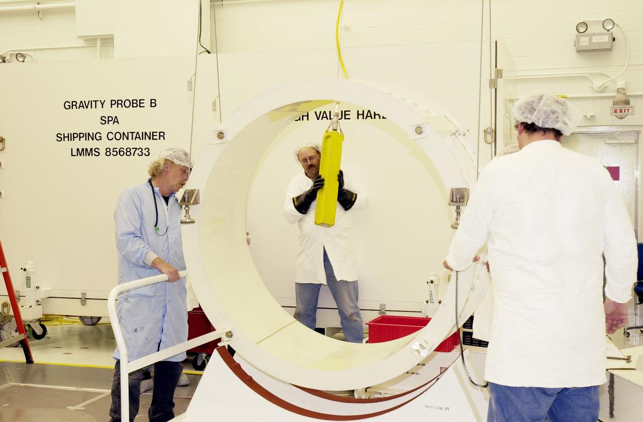
Workers in the spacecraft processing facility on North Vandenberg Air Force Base get ready to begin processing the Gravity Probe B experiment, including setting up mechanical and electrical ground support equipment, making necessary connections and conditioning the spacecraft battery. The Gravity Probe B will launch a payload of four gyroscopes into low-Earth polar orbit to test two extraordinary predictions of Albert Einstein’s general theory of relativity: the geodetic effect (how space and time are warped by the presence of the Earth) and frame dragging (how Earth’s rotation drags space and time around with it). Once in orbit, for 18 months each gyroscope’s spin axis will be monitored as it travels through local spacetime, observing and measuring these effects. The experiment was developed by Stanford University, Lockheed Martin and NASA’s Marshall Space Flight Center.
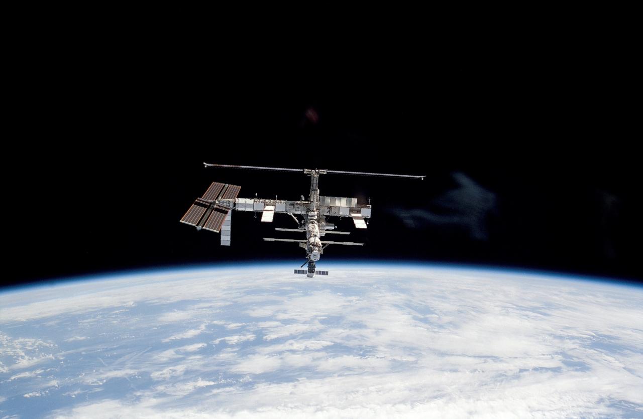
STS115-318-026 (17 Sept. 2006) --- Backdropped by the blackness of space and Earth's horizon, the International Space Station moves away from Space Shuttle Atlantis. Earlier the STS-115 and Expedition 13 crews concluded six days of cooperative work onboard the shuttle and station. Undocking of the two spacecraft occurred at 7:50 a.m. (CDT) on Sept. 17, 2006. Atlantis left the station with a new, second pair of 240-foot solar wings, attached to a new 17.5-ton section of truss with batteries, electronics and a giant rotating joint. The new solar arrays eventually will double the station's onboard power when their electrical systems are brought online during the next shuttle flight, planned for launch in December.
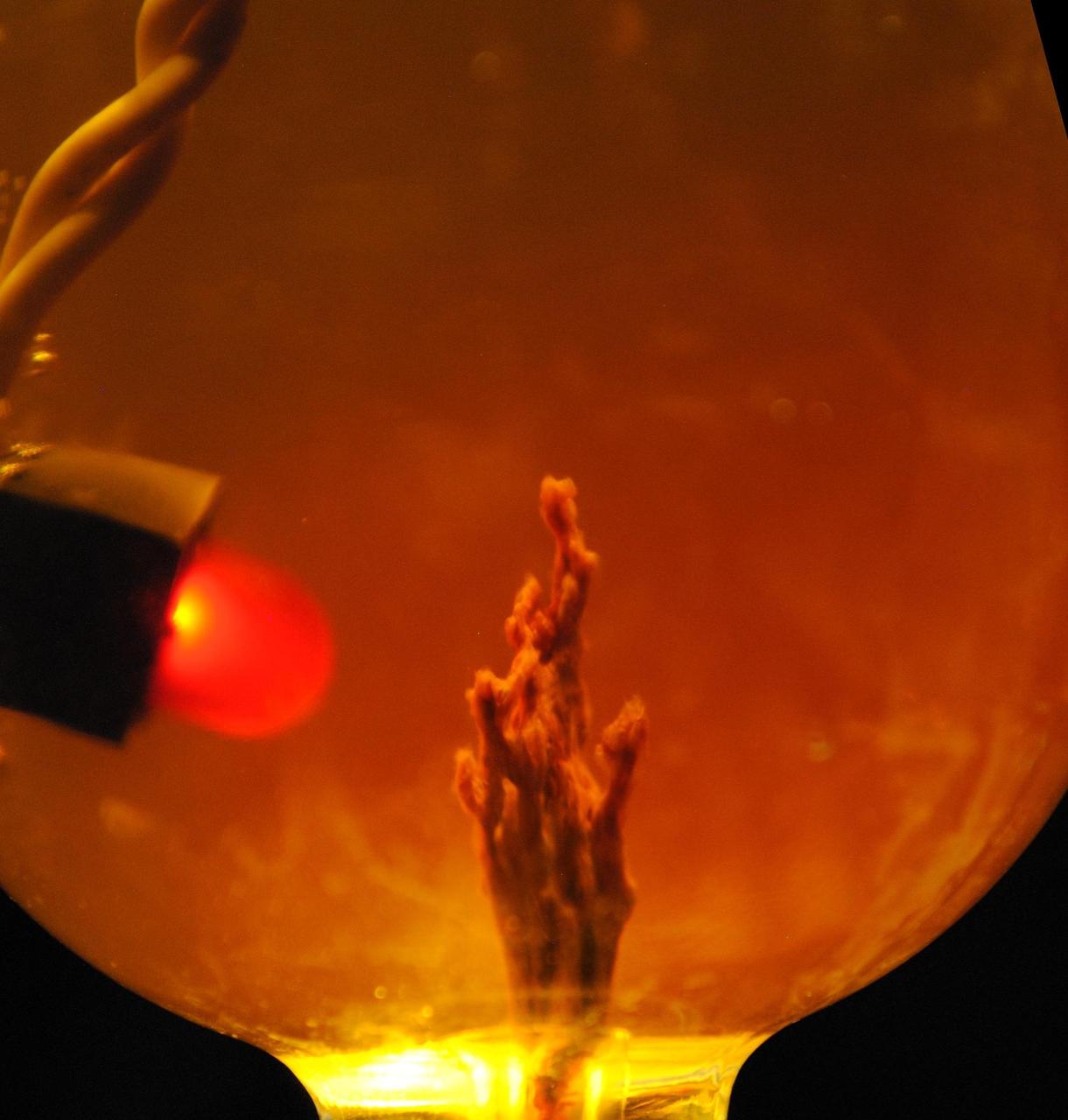
This photo simulation shows a laboratory-created "chemical garden," which is a chimney-like structure found at bubbling vents on the seafloor. Some researchers think life on Earth might have got its start at structures like these billions of years ago, partly due to their ability to transfer electrical currents -- an essential trait of life as we know it. The battery-like property of these chemical gardens was demonstrated by linking several together in series to light an LED (light-emitting diode) bulb. In this photo simulation, the bulb is not really attached to the chimney. The chimney membranes are made of iron sulfides and iron hydroxides, geologic materials that conduct electrons. JPL's research team is part of the Icy Worlds team of the NASA Astrobiology Institute, based at NASA's Ames Research Center in Moffett Field, California. JPL is managed by the California Institute of Technology in Pasadena for NASA. http://photojournal.jpl.nasa.gov/catalog/PIA19834
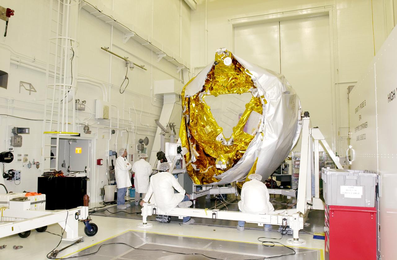
Workers in the spacecraft processing facility on North Vandenberg Air Force Base get ready to begin processing the Gravity Probe B experiment, including setting up mechanical and electrical ground support equipment, making necessary connections and conditioning the spacecraft battery. The Gravity Probe B will launch a payload of four gyroscopes into low-Earth polar orbit to test two extraordinary predictions of Albert Einstein’s general theory of relativity: the geodetic effect (how space and time are warped by the presence of the Earth) and frame dragging (how Earth’s rotation drags space and time around with it). Once in orbit, for 18 months each gyroscope’s spin axis will be monitored as it travels through local spacetime, observing and measuring these effects. The experiment was developed by Stanford University, Lockheed Martin and NASA’s Marshall Space Flight Center.
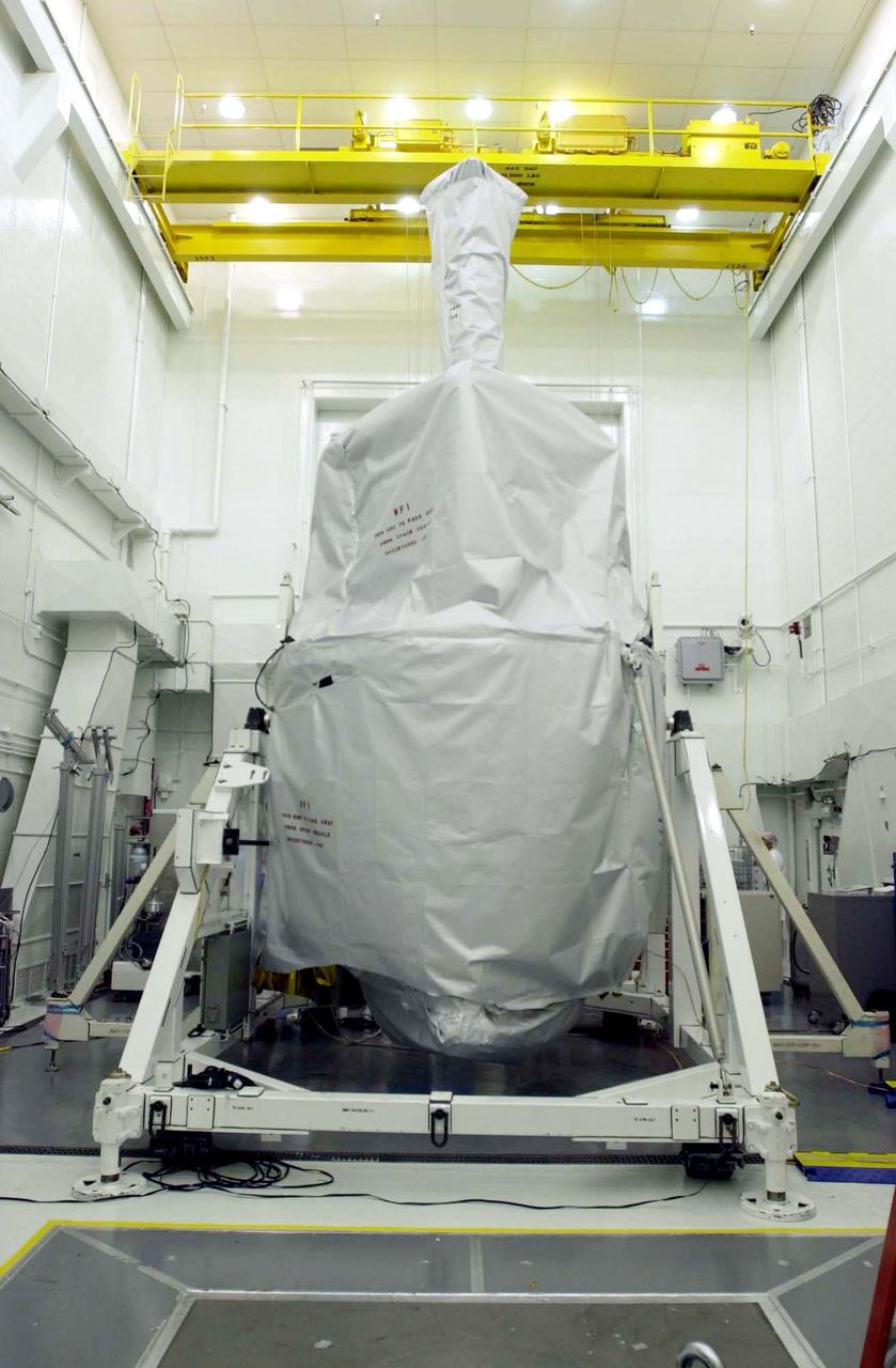
In the spacecraft processing facility on North Vandenberg Air Force Base, workers prepare to remove the soft shipping cover from the Gravity Probe B experiment. Immediate processing includes setting up mechanical and electrical ground support equipment, making necessary connections and conditioning the spacecraft battery. The Gravity Probe B will launch a payload of four gyroscopes into low-Earth polar orbit to test two extraordinary predictions of Albert Einstein’s general theory of relativity: the geodetic effect (how space and time are warped by the presence of the Earth) and frame dragging (how Earth’s rotation drags space and time around with it). Once in orbit, for 18 months each gyroscope’s spin axis will be monitored as it travels through local spacetime, observing and measuring these effects. The experiment was developed by Stanford University, Lockheed Martin and NASA’s Marshall Space Flight Center.
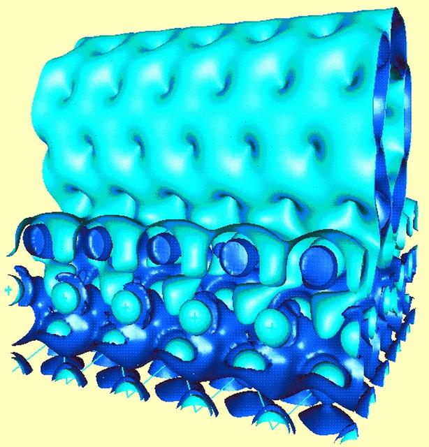
NASA is looking to biological techniques that are millions of years old to help it develop new materials and nanotechnology for the 21st century. Sponsored by NASA, Jerzy Bernholc, a principal investigator in the microgravity materials science program and a physics professor at North Carolina State University, Bernholc works with very large-scale computations to model carbon molecules as they assemble themselves to form nanotubes. The strongest confirmed material known, nanotubes are much stronger than graphite, a more common material made of carbon, and weigh six times less than steel. Nanotubes have potential uses such as strain gauges, advanced electronic devices, amd batteries. The strength, light weight, and conductive qualities of nanotubes, shown in light blue in this computed electron distribution, make them excellent components of nanoscale devices. One way to conduct electricity to such devices is through contact with aluminum, shown in dark blue.
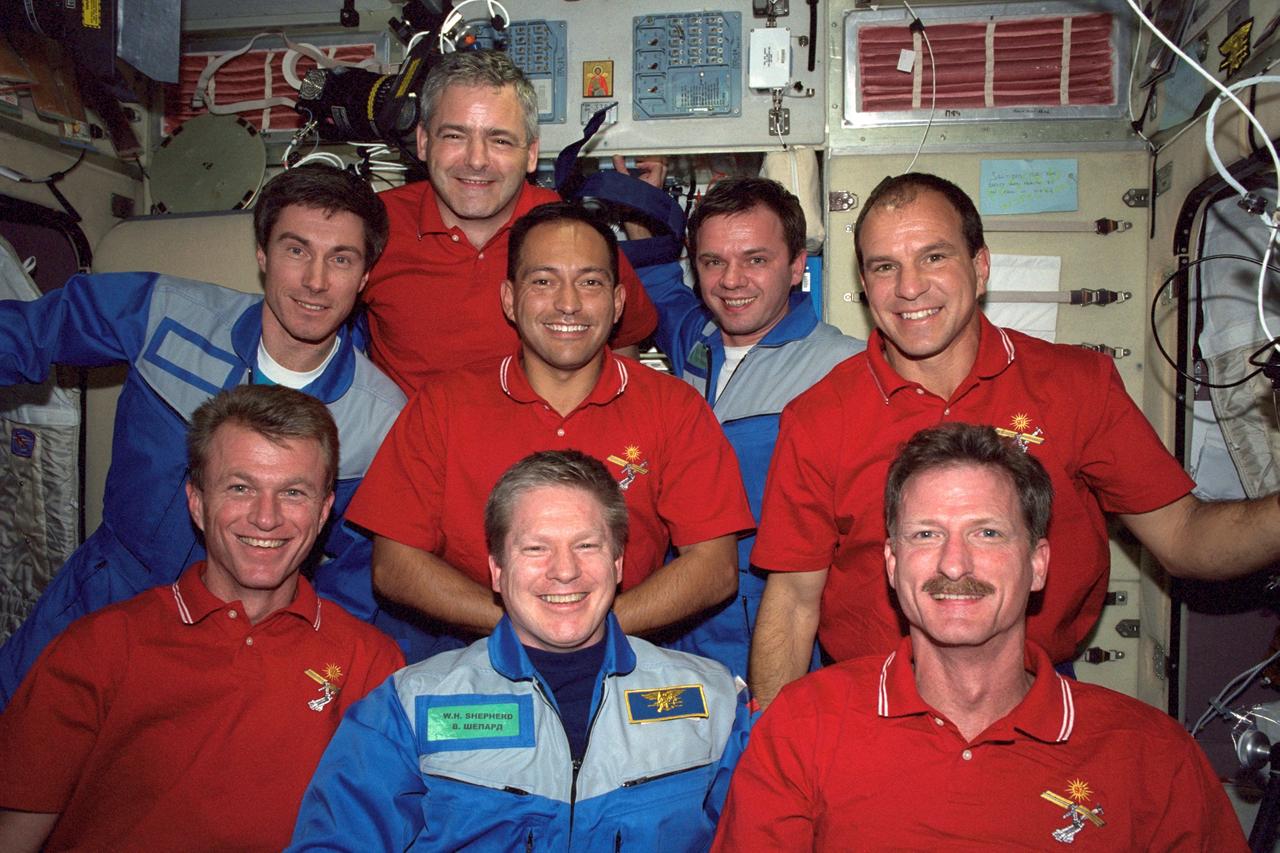
In this image, the five STS-97 crew members pose with the 3 members of the Expedition One crew onboard the International Space Station (ISS) for the first ever traditional onboard portrait taken in the Zvezda Service Module. On the front row, left to right, are astronauts Brent W. Jett, Jr., STS-97 commander; William M. Shepherd, Expedition One mission commander; and Joseph R. Tarner, STS-97 mission specialist. On the second row, from the left are Cosmonaut Sergei K. Krikalev, Expedition One flight engineer; astronaut Carlos I. Noriega, STS-97 mission specialist; cosmonaut Yuri P. Gidzenko, Expedition One Soyuz commander; and Michael J. Bloomfield, STS-97 pilot. Behind them is astronaut Marc Garneau, STS-97 mission specialist representing the Canadian Space Agency (CSA). The primary objective of the STS-97 mission was the delivery, assembly, and activation of the U.S. electrical power system onboard the International Space Station (ISS). The electrical power system, which is built into a 73-meter (240-foot) long solar array structure consists of solar arrays, radiators, batteries, and electronics. The entire 15.4-metric ton (17-ton) package is called the P6 Integrated Truss Segment, and is the heaviest and largest element yet delivered to the station aboard a space shuttle. The electrical system will eventually provide the power necessary for the first ISS crews to live and work in the U.S. segment. The STS-97 crew of five launched aboard the Space Shuttle Orbiter Endeavor on November 30, 2000 for an 11 day mission.
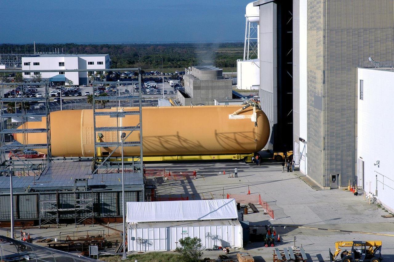
KENNEDY SPACE CENTER, FLA. - Viewed from the roof of the Launch Control Center in the Launch Complex 39 Area, the newly redesigned External Tank is seen moving into the Vehicle Assembly Building. In the transfer aisle of the VAB, the tank will be raised from a horizontal to a vertical position, then lifted high up into a storage cell, or “checkout cell,” where it will undergo inspections of the mechanical, electrical and thermal protection systems. New processing activities resulting from re-design of the tank include inspection of the bipod heater and External Tank separation camera, which includes charging the camera batteries. The tank will be then prepared for mating to the Solid Rocket Boosters. When preparations are complete, the tank will be lifted from the checkout cell, moved across the transfer aisle and into High Bay 1, where it will be lowered and attached to the boosters, which are sitting on the Mobile Launch Platform. The tank is designated for the Return to Flight mission, STS-114, targeted for a launch opportunity beginning in May. The seven-member Discovery crew will fly to the International Space Station primarily to test and evaluate new procedures for flight safety, including Space Shuttle inspection and repair techniques.
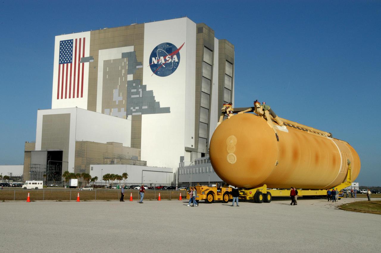
KENNEDY SPACE CENTER, FLA. - The newly redesigned External Tank is slowly moved from the dock in the Launch Complex 39 Area Turn Basin on its way to the Vehicle Assembly Building, seen at left. The tank arrived Jan. 5 after a 900-mile sea voyage aboard NASA’s specially designed barge, Pegasus, from the Michoud Assembly Facility in New Orleans. In the transfer aisle of the VAB, the tank will be raised from a horizontal to a vertical position, then lifted high up into a storage cell, or “checkout cell,” where it will undergo inspections of the mechanical, electrical and thermal protection systems. New processing activities resulting from re-design of the tank include inspection of the bipod heater and External Tank separation camera, which includes charging the camera batteries. The tank will be then prepared for mating to the Solid Rocket Boosters. When preparations are complete, the tank will be lifted from the checkout cell, moved across the transfer aisle and into High Bay 1, where it will be lowered and attached to the boosters, which are sitting on the Mobile Launch Platform. The tank is designated for the Return to Flight mission, STS-114, targeted for a launch opportunity beginning in May. The seven-member Discovery crew will fly to the International Space Station primarily to test and evaluate new procedures for flight safety, including Space Shuttle inspection and repair techniques.
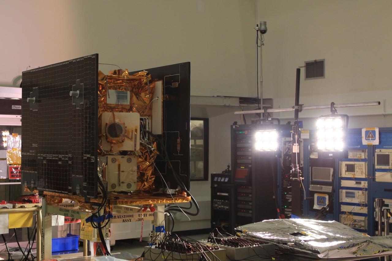
CAPE CANAVERAL, Fla. -- Testing of the solar arrays on NASA's Gravity Recovery and Interior Laboratory-A, or GRAIL-A, spacecraft is under way in Astrotech Space Operation's payload processing facility in Titusville, Fla., to ensure that they will function as planned during the mission. The electrical power subsystem on each of GRAIL's twin spacecraft includes two solar arrays and a lithium ion battery. Each solar array is capable of producing no less than 700 watts. They will be deployed shortly after separation from the launch vehicle and remain fixed throughout the mission. GRAIL will fly in tandem orbits around the moon for several months to measure its gravity field. GRAIL's primary science objectives are to determine the structure of the lunar interior, from crust to core, and to advance understanding of the thermal evolution of the moon. Launch aboard a United Launch Alliance Delta II rocket from Space Launch Complex 17B on Cape Canaveral Air Force Station is scheduled for Sept. 8. For more information, visit http://www.nasa.gov/grail. Photo credit: NASA/Frankie Martin
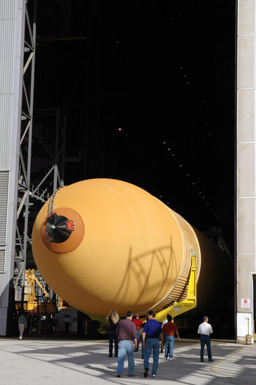
KENNEDY SPACE CENTER, FLA. - Accompanied by KSC employees, the newly redesigned External Tank rolls into the Vehicle Assembly Building. The tank arrived Jan. 5 after a 900-mile sea voyage aboard NASA’s specially designed barge, Pegasus, from the Michoud Assembly Facility in New Orleans. In the transfer aisle of the VAB, the tank will be raised from a horizontal to a vertical position, then lifted high up into a storage cell, or “checkout cell,” where it will undergo inspections of the mechanical, electrical and thermal protection systems. New processing activities resulting from re-design of the tank include inspection of the bipod heater and External Tank separation camera, which includes charging the camera batteries. The tank will be then prepared for mating to the Solid Rocket Boosters. When preparations are complete, the tank will be lifted from the checkout cell, moved across the transfer aisle and into High Bay 1, where it will be lowered and attached to the boosters, which are sitting on the Mobile Launch Platform. The tank is designated for the Return to Flight mission, STS-114, targeted for a launch opportunity beginning in May. The seven-member Discovery crew will fly to the International Space Station primarily to test and evaluate new procedures for flight safety, including Space Shuttle inspection and repair techniques.
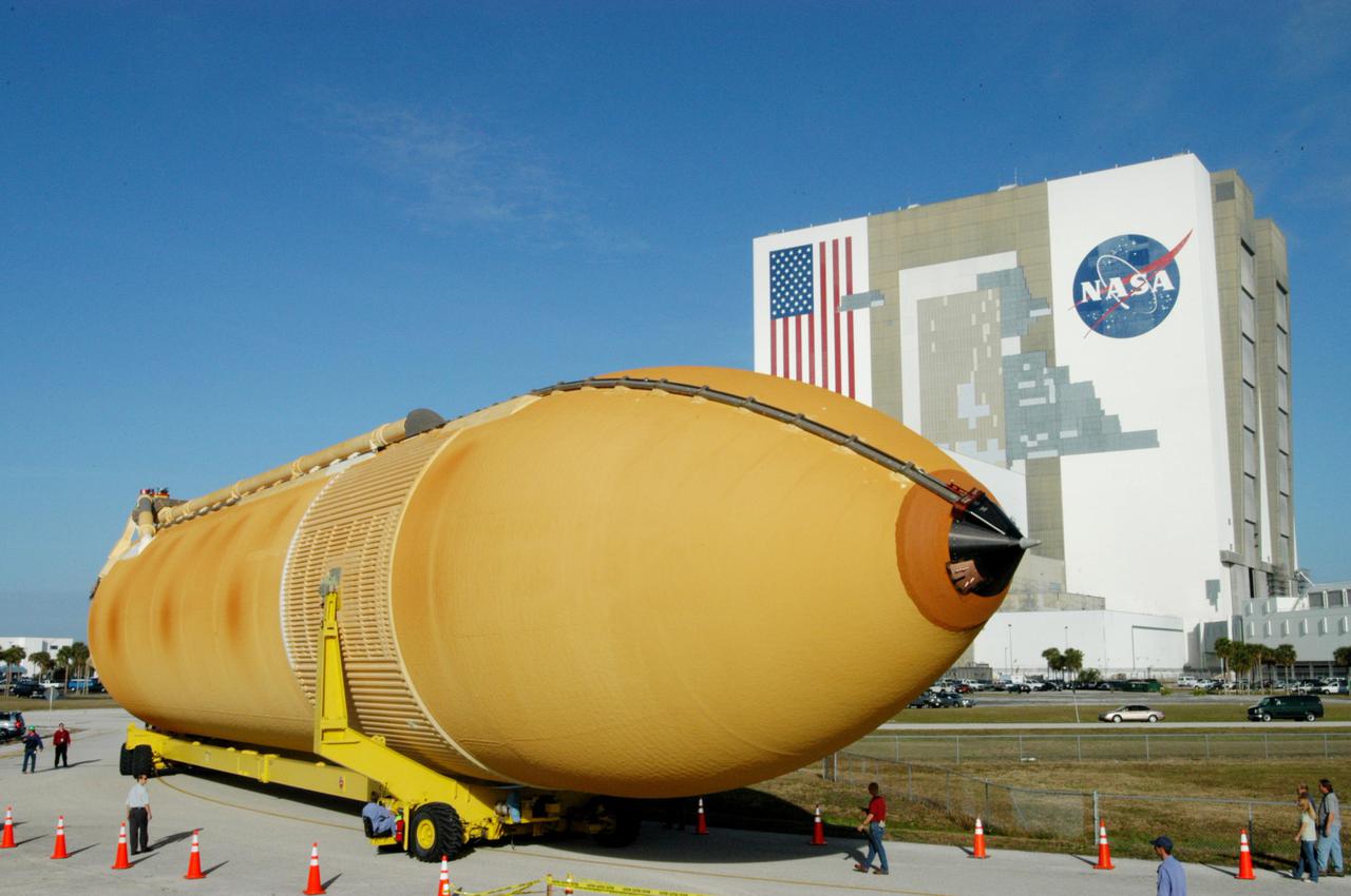
KENNEDY SPACE CENTER, FLA. - The newly redesigned External Tank turns the corner of the Launch Complex 39 Area Turn Basin parking area on its way to the Vehicle Assembly Building, seen at right. The tank arrived Jan. 5 after a 900-mile sea voyage aboard NASA’s specially designed barge, Pegasus, from the Michoud Assembly Facility in New Orleans. In the transfer aisle of the VAB, the tank will be raised from a horizontal to a vertical position, then lifted high up into a storage cell, or “checkout cell,” where it will undergo inspections of the mechanical, electrical and thermal protection systems. New processing activities resulting from re-design of the tank include inspection of the bipod heater and External Tank separation camera, which includes charging the camera batteries. The tank will be then prepared for mating to the Solid Rocket Boosters. When preparations are complete, the tank will be lifted from the checkout cell, moved across the transfer aisle and into High Bay 1, where it will be lowered and attached to the boosters, which are sitting on the Mobile Launch Platform. The tank is designated for the Return to Flight mission, STS-114, targeted for a launch opportunity beginning in May. The seven-member Discovery crew will fly to the International Space Station primarily to test and evaluate new procedures for flight safety, including Space Shuttle inspection and repair techniques.

KENNEDY SPACE CENTER, FLA. - Media view the newly redesigned External Tank after its off-loading from the barge that carried it from the Michoud Assembly Facility in New Orleans. The tank is being transported to the Vehicle Assembly Building. In the transfer aisle of the VAB, the tank will be raised from a horizontal to a vertical position, then lifted high up into a storage cell, or “checkout cell,” where it will undergo inspections of the mechanical, electrical and thermal protection systems. New processing activities resulting from re-design of the tank include inspection of the bipod heater and External Tank separation camera, which includes charging the camera batteries. The tank will be then prepared for mating to the Solid Rocket Boosters. When preparations are complete, the tank will be lifted from the checkout cell, moved across the transfer aisle and into High Bay 1, where it will be lowered and attached to the boosters, which are sitting on the Mobile Launch Platform. The tank is designated for the Return to Flight mission, STS-114, targeted for a launch opportunity beginning in May. The seven-member Discovery crew will fly to the International Space Station primarily to test and evaluate new procedures for flight safety, including Space Shuttle inspection and repair techniques.
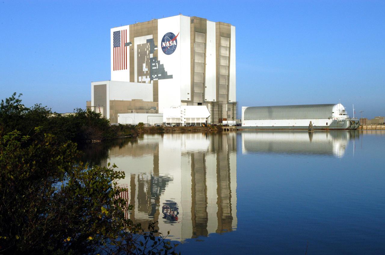
KENNEDY SPACE CENTER, FLA. - NASA’s specially designed barge, Pegasus, is docked in the Launch Complex 39 Area Turn Basin with its cargo of the newly redesigned External Tank. The barge was towed from the Michoud Assembly Facility in New Orleans. The tank will be off-loaded and transported to the Vehicle Assembly Building, seen at left of the barge. In the transfer aisle of the VAB, the tank will be raised from a horizontal to a vertical position, then lifted high up into a storage cell, or “checkout cell,” where it will undergo inspections of the mechanical, electrical and thermal protection systems. New processing activities resulting from re-design of the tank include inspection of the bipod heater and External Tank separation camera, which includes charging the camera batteries. The tank will be then prepared for mating to the Solid Rocket Boosters. When preparations are complete, the tank will be lifted from the checkout cell, moved across the transfer aisle and into High Bay 1, where it will be lowered and attached to the boosters, which are sitting on the Mobile Launch Platform. The tank is designated for the Return to Flight mission, STS-114, targeted for a launch opportunity beginning in May. The seven-member Discovery crew will fly to the International Space Station primarily to test and evaluate new procedures for flight safety, including Space Shuttle inspection and repair techniques.
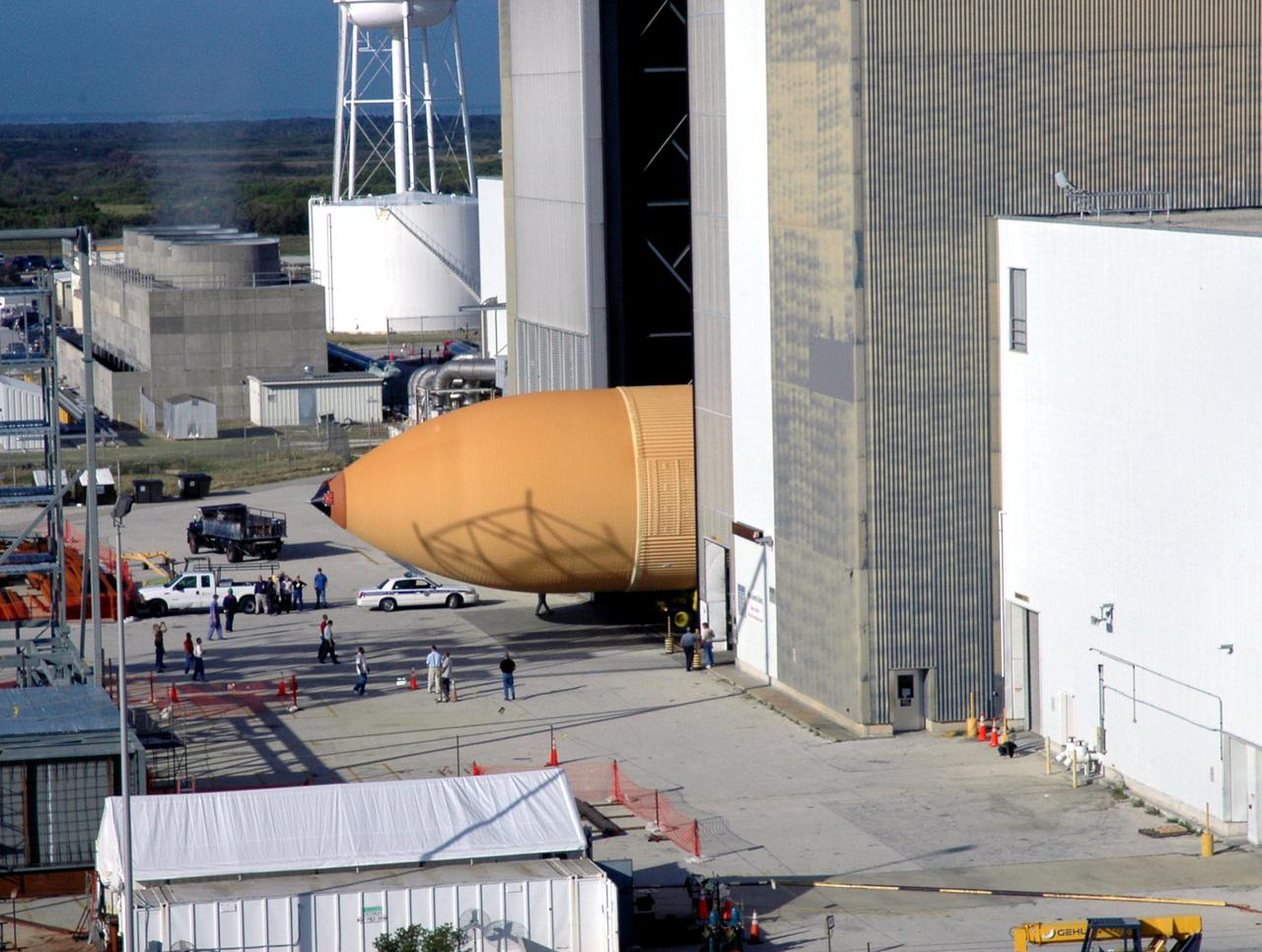
KENNEDY SPACE CENTER, FLA. - Viewed from the roof of the Launch Control Center in the Launch Complex 39 Area, the newly redesigned External Tank disappears into the Vehicle Assembly Building. In the transfer aisle of the VAB, the tank will be raised from a horizontal to a vertical position, then lifted high up into a storage cell, or “checkout cell,” where it will undergo inspections of the mechanical, electrical and thermal protection systems. New processing activities resulting from re-design of the tank include inspection of the bipod heater and External Tank separation camera, which includes charging the camera batteries. The tank will be then prepared for mating to the Solid Rocket Boosters. When preparations are complete, the tank will be lifted from the checkout cell, moved across the transfer aisle and into High Bay 1, where it will be lowered and attached to the boosters, which are sitting on the Mobile Launch Platform. The tank is designated for the Return to Flight mission, STS-114, targeted for a launch opportunity beginning in May. The seven-member Discovery crew will fly to the International Space Station primarily to test and evaluate new procedures for flight safety, including Space Shuttle inspection and repair techniques.
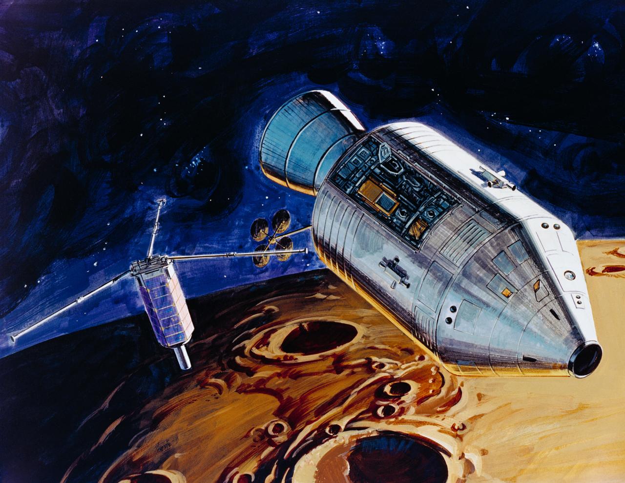
S71-39481 (July 1971) --- An artist's concept showing TRW's small lunar subsatellite being ejected into lunar orbit from the SIM bay of the Apollo 15 Service Module. The 80-pound satellite will remain in orbit a year or more, carrying scientific experiments to study space in the vicinity of the moon. The satellite carries three experiments: S-Band Transponder; Particle Shadows/Boundary Layer Experiment; and Subsatellite Magnetometer Experiment. The subsatellite is housed in a container resembling a rural mailbox, and when deployed is spring-ejected out-of-plane at 4 fps with a spin rate of 140 rpm. After the satellite booms are deployed, the spin rate is stabilized at about 12 rpm. The subsatellite is 31 inches long and has a 14 inch hexagonal diameter. The exact weight is 78.5 pounds. The folded booms deploy to a length of five feet. Subsatellite electrical power is supplied by a solar cell array outputting 25 watts for dayside operation and a rechargeable silver-cadmium battery for nightside passes.
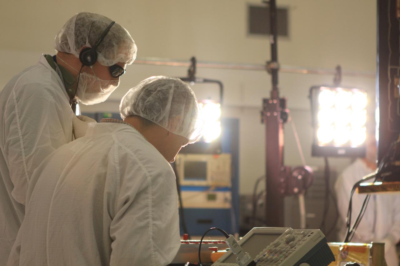
CAPE CANAVERAL, Fla. -- Lockheed Martin technicians in Astrotech Space Operation's payload processing facility in Titusville, Fla., test the solar arrays on NASA's Gravity Recovery and Interior Laboratory-A, or GRAIL-A, spacecraft to ensure that they will function as planned during the mission. The electrical power subsystem on each of GRAIL's twin spacecraft includes two solar arrays and a lithium ion battery. Each solar array is capable of producing no less than 700 watts. They will be deployed shortly after separation from the launch vehicle and remain fixed throughout the mission. GRAIL will fly in tandem orbits around the moon for several months to measure its gravity field. GRAIL's primary science objectives are to determine the structure of the lunar interior, from crust to core, and to advance understanding of the thermal evolution of the moon. Launch aboard a United Launch Alliance Delta II rocket from Space Launch Complex 17B on Cape Canaveral Air Force Station is scheduled for Sept. 8. For more information, visit http://www.nasa.gov/grail. Photo credit: NASA/Frankie Martin
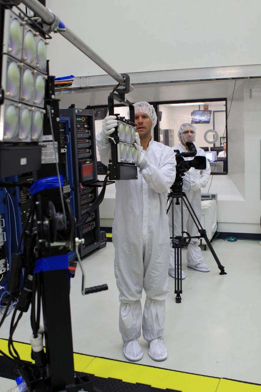
CAPE CANAVERAL, Fla. -- Lockheed Martin technicians in Astrotech Space Operation's payload processing facility in Titusville, Fla., prepare to test the solar arrays on NASA's Gravity Recovery and Interior Laboratory-A, or GRAIL-A, spacecraft to ensure that they will function as planned during the mission. The electrical power subsystem on each of GRAIL's twin spacecraft includes two solar arrays and a lithium ion battery. Each solar array is capable of producing no less than 700 watts. They will be deployed shortly after separation from the launch vehicle and remain fixed throughout the mission. GRAIL will fly in tandem orbits around the moon for several months to measure its gravity field. GRAIL's primary science objectives are to determine the structure of the lunar interior, from crust to core, and to advance understanding of the thermal evolution of the moon. Launch aboard a United Launch Alliance Delta II rocket from Space Launch Complex 17B on Cape Canaveral Air Force Station is scheduled for Sept. 8. For more information, visit http://www.nasa.gov/grail. Photo credit: NASA/Frankie Martin
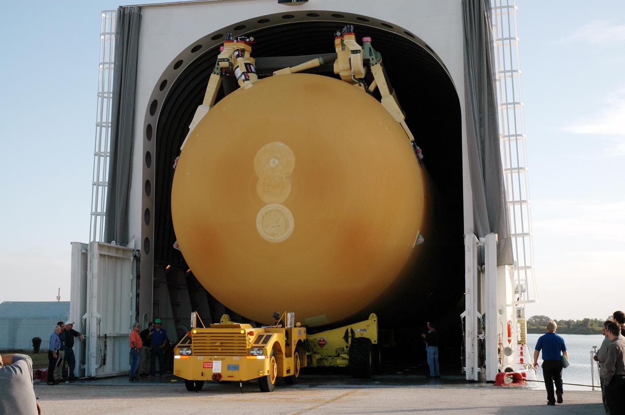
KENNEDY SPACE CENTER, FLA. - Media view the newly redesigned External Tank as a transporter begins off-loading it from the barge that carried it from the Michoud Assembly Facility in New Orleans. The tank is being transported to the Vehicle Assembly Building. In the transfer aisle of the VAB, the tank will be raised from a horizontal to a vertical position, then lifted high up into a storage cell, or “checkout cell,” where it will undergo inspections of the mechanical, electrical and thermal protection systems. New processing activities resulting from re-design of the tank include inspection of the bipod heater and External Tank separation camera, which includes charging the camera batteries. The tank will be then prepared for mating to the Solid Rocket Boosters. When preparations are complete, the tank will be lifted from the checkout cell, moved across the transfer aisle and into High Bay 1, where it will be lowered and attached to the boosters, which are sitting on the Mobile Launch Platform. The tank is designated for the Return to Flight mission, STS-114, targeted for a launch opportunity beginning in May. The seven-member Discovery crew will fly to the International Space Station primarily to test and evaluate new procedures for flight safety, including Space Shuttle inspection and repair techniques.
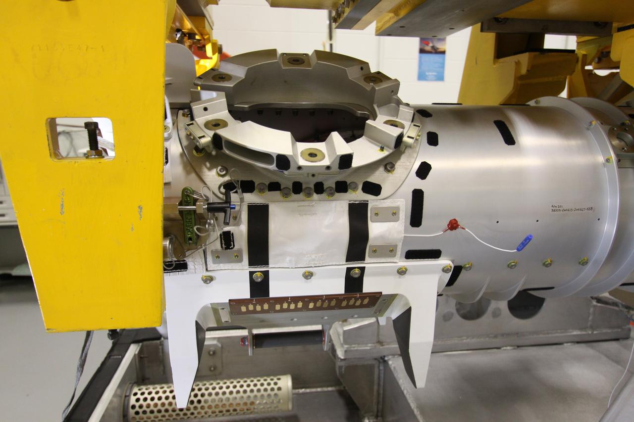
CAPE CANAVERAL, Fla. - In the Remote Manipulator System Lab inside the Vehicle Assembly Building at NASA's Kennedy Space Center in Florida, this close-up shows the forward transition and X-guide restraint of the inspection boom assembly, or IBA, on space shuttle Atlantis' orbiter boom sensor system, or OBSS. The IBA is removed from the shuttle every other processing flow for a detailed inspection. After five consecutive flights, all IBA internal components are submitted to a thorough electrical checkout in the lab. The 50-foot-long OBSS attaches to the end of the shuttle’s robotic arm and supports the cameras and laser systems used to inspect the shuttle’s thermal protection system while in space. Atlantis is next slated to deliver an Integrated Cargo Carrier and Russian-built Mini Research Module to the International Space Station on the STS-132 mission. The second in a series of new pressurized components for Russia, the module will be permanently attached to the Zarya module. Three spacewalks are planned to store spare components outside the station, including six spare batteries, a boom assembly for the Ku-band antenna and spares for the Canadian Dextre robotic arm extension. A radiator, airlock and European robotic arm for the Russian Multi-purpose Laboratory Module also are payloads on the flight. Launch is targeted for May 14, 2010. Photo credit: NASA/Jack Pfaller
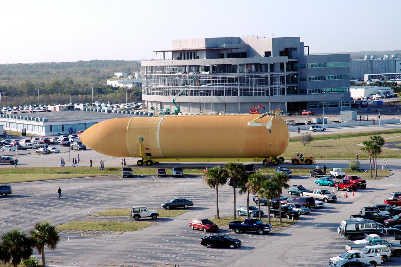
KENNEDY SPACE CENTER, FLA. - Viewed from the roof of the Launch Control Center in the Launch Complex 39 Area, the newly redesigned External Tank is seen moving past the parking area on its way to the Vehicle Assembly Building. Behind the tank is Operations Support Building II, currently under construction. In the transfer aisle of the VAB, the tank will be raised from a horizontal to a vertical position, then lifted high up into a storage cell, or “checkout cell,” where it will undergo inspections of the mechanical, electrical and thermal protection systems. New processing activities resulting from re-design of the tank include inspection of the bipod heater and External Tank separation camera, which includes charging the camera batteries. The tank will be then prepared for mating to the Solid Rocket Boosters. When preparations are complete, the tank will be lifted from the checkout cell, moved across the transfer aisle and into High Bay 1, where it will be lowered and attached to the boosters, which are sitting on the Mobile Launch Platform. The tank is designated for the Return to Flight mission, STS-114, targeted for a launch opportunity beginning in May. The seven-member Discovery crew will fly to the International Space Station primarily to test and evaluate new procedures for flight safety, including Space Shuttle inspection and repair techniques.
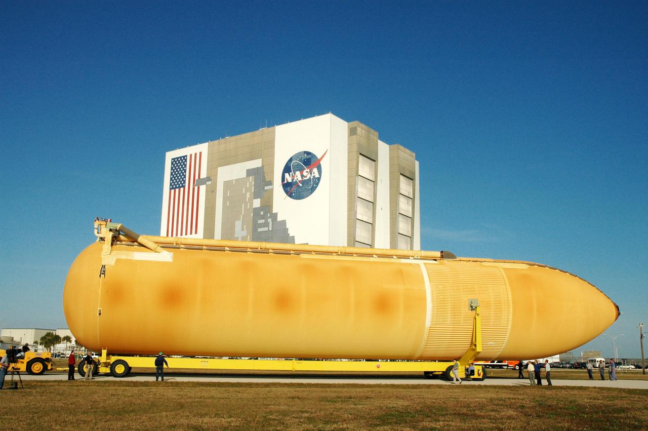
KENNEDY SPACE CENTER, FLA. - The newly redesigned External Tank wends its way through the parking area at the Launch Complex 39 Area Turn Basin on its way to the Vehicle Assembly Building, seen behind it. The tank arrived Jan. 5 after a 900-mile sea voyage aboard NASA’s specially designed barge, Pegasus, from the Michoud Assembly Facility in New Orleans. In the transfer aisle of the VAB, the tank will be raised from a horizontal to a vertical position, then lifted high up into a storage cell, or “checkout cell,” where it will undergo inspections of the mechanical, electrical and thermal protection systems. New processing activities resulting from re-design of the tank include inspection of the bipod heater and External Tank separation camera, which includes charging the camera batteries. The tank will be then prepared for mating to the Solid Rocket Boosters. When preparations are complete, the tank will be lifted from the checkout cell, moved across the transfer aisle and into High Bay 1, where it will be lowered and attached to the boosters, which are sitting on the Mobile Launch Platform. The tank is designated for the Return to Flight mission, STS-114, targeted for a launch opportunity beginning in May. The seven-member Discovery crew will fly to the International Space Station primarily to test and evaluate new procedures for flight safety, including Space Shuttle inspection and repair techniques.
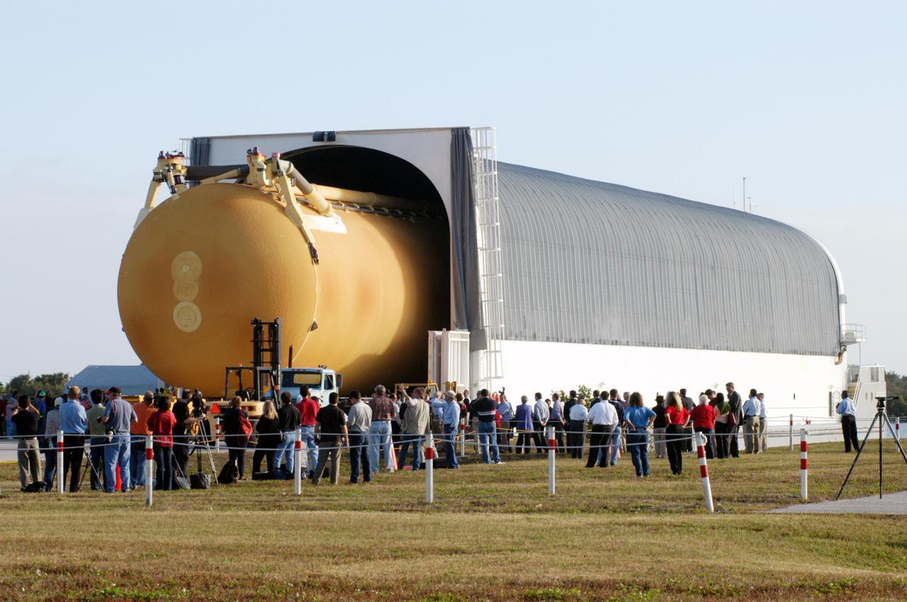
KENNEDY SPACE CENTER, FLA. - Media view the newly redesigned External Tank as it is off-loaded from the barge that carried it from the Michoud Assembly Facility in New Orleans. The tank is being transported to the Vehicle Assembly Building. In the transfer aisle of the VAB, the tank will be raised from a horizontal to a vertical position, then lifted high up into a storage cell, or “checkout cell,” where it will undergo inspections of the mechanical, electrical and thermal protection systems. New processing activities resulting from re-design of the tank include inspection of the bipod heater and External Tank separation camera, which includes charging the camera batteries. The tank will be then prepared for mating to the Solid Rocket Boosters. When preparations are complete, the tank will be lifted from the checkout cell, moved across the transfer aisle and into High Bay 1, where it will be lowered and attached to the boosters, which are sitting on the Mobile Launch Platform. The tank is designated for the Return to Flight mission, STS-114, targeted for a launch opportunity beginning in May. The seven-member Discovery crew will fly to the International Space Station primarily to test and evaluate new procedures for flight safety, including Space Shuttle inspection and repair techniques.
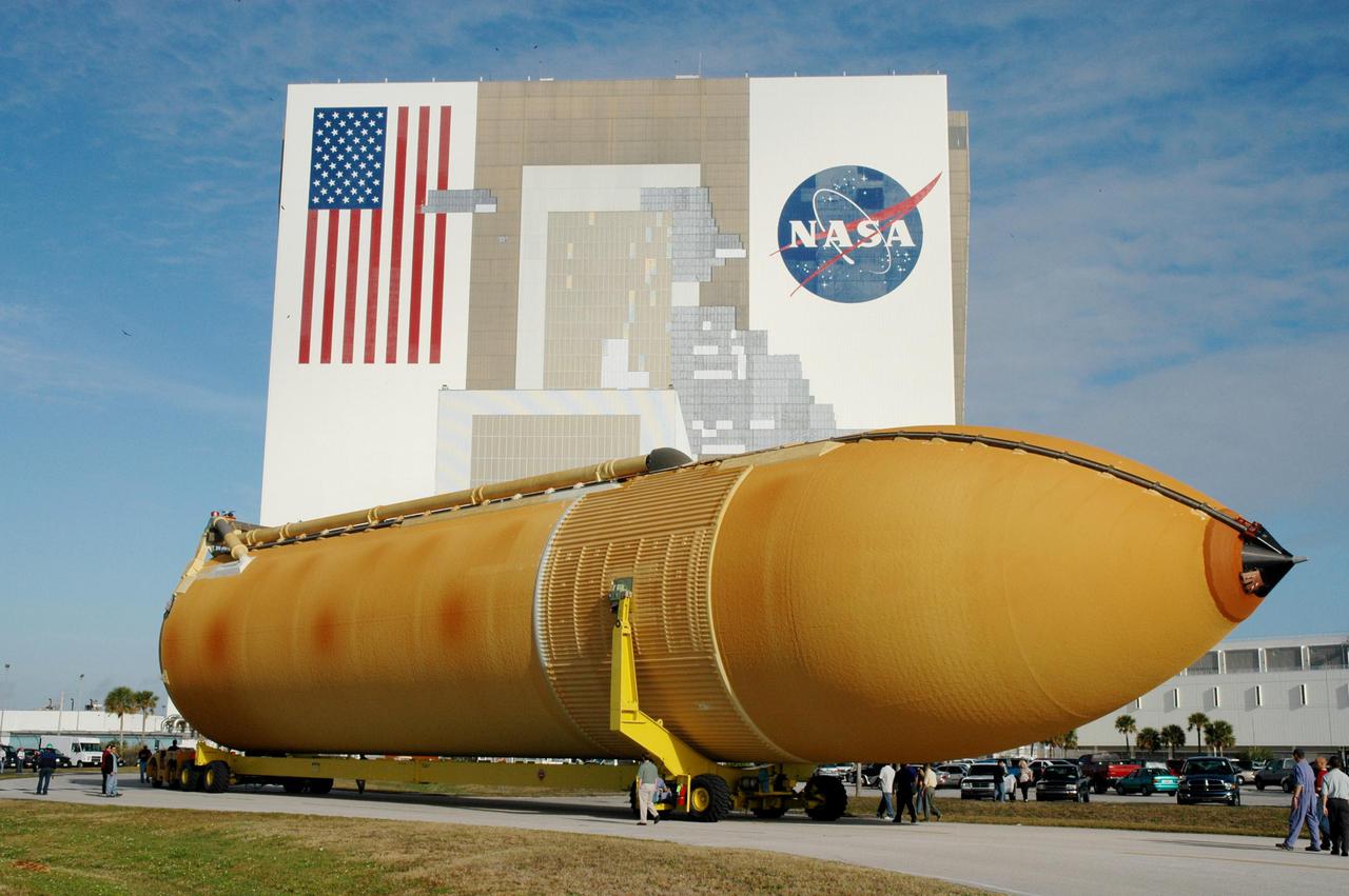
KENNEDY SPACE CENTER, FLA. - The newly redesigned External Tank moves closer to its destination, the Vehicle Assembly Building, seen behind it. The tank arrived Jan. 5 after a 900-mile sea voyage aboard NASA’s specially designed barge, Pegasus, from the Michoud Assembly Facility in New Orleans. In the transfer aisle of the VAB, the tank will be raised from a horizontal to a vertical position, then lifted high up into a storage cell, or “checkout cell,” where it will undergo inspections of the mechanical, electrical and thermal protection systems. New processing activities resulting from re-design of the tank include inspection of the bipod heater and External Tank separation camera, which includes charging the camera batteries. The tank will be then prepared for mating to the Solid Rocket Boosters. When preparations are complete, the tank will be lifted from the checkout cell, moved across the transfer aisle and into High Bay 1, where it will be lowered and attached to the boosters, which are sitting on the Mobile Launch Platform. The tank is designated for the Return to Flight mission, STS-114, targeted for a launch opportunity beginning in May. The seven-member Discovery crew will fly to the International Space Station primarily to test and evaluate new procedures for flight safety, including Space Shuttle inspection and repair techniques.
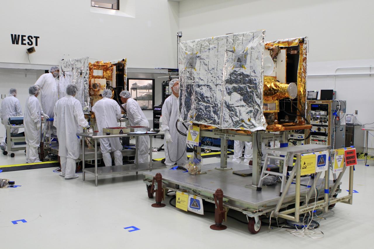
CAPE CANAVERAL, Fla. -- NASA's twin Gravity Recovery and Interior Laboratory spacecraft are positioned side-by-side in Astrotech Space Operation's payload processing facility in Titusville, Fla. Lockheed Martin technicians are performing testing the solar arrays on GRAIL-A to ensure that they will function as planned during the mission. The electrical power subsystem on each of GRAIL's twin spacecraft includes two solar arrays and a lithium ion battery. Each solar array is capable of producing no less than 700 watts. They will be deployed shortly after separation from the launch vehicle and remain fixed throughout the mission. GRAIL will fly in tandem orbits around the moon for several months to measure its gravity field. GRAIL's primary science objectives are to determine the structure of the lunar interior, from crust to core, and to advance understanding of the thermal evolution of the moon. Launch aboard a United Launch Alliance Delta II rocket from Space Launch Complex 17B on Cape Canaveral Air Force Station is scheduled for Sept. 8. For more information, visit http://www.nasa.gov/grail. Photo credit: NASA/Frankie Martin
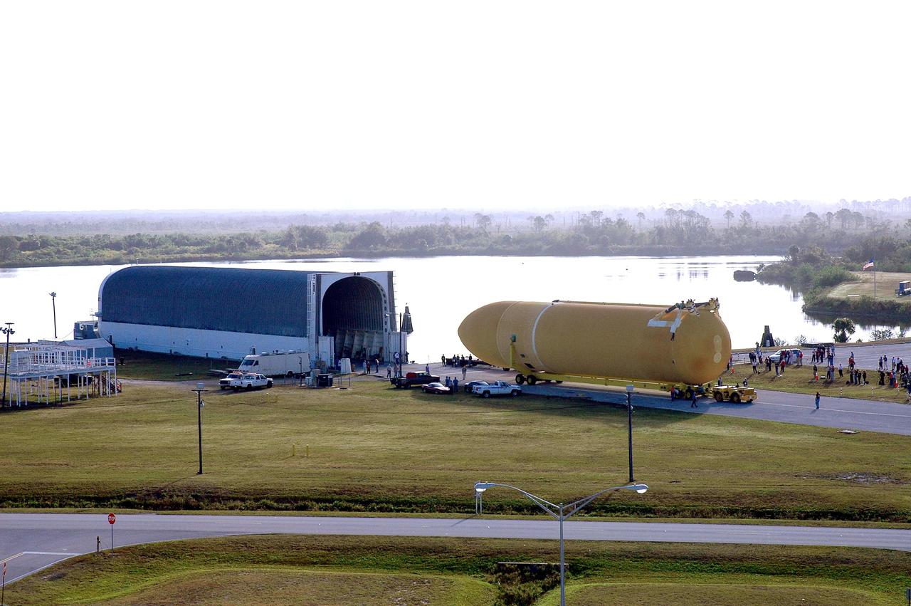
KENNEDY SPACE CENTER, FLA. - Viewed from the roof of the Launch Control Center, the newly redesigned External Tank is seen after being off-loaded from NASA’s specially designed barge, Pegasus, which delivered it from the Michoud Assembly Facility in New Orleans. The tank is being transferred to the Vehicle Assembly Building. In the transfer aisle of the VAB, the tank will be raised from a horizontal to a vertical position, then lifted high up into a storage cell, or “checkout cell,” where it will undergo inspections of the mechanical, electrical and thermal protection systems. New processing activities resulting from re-design of the tank include inspection of the bipod heater and External Tank separation camera, which includes charging the camera batteries. The tank will be then prepared for mating to the Solid Rocket Boosters. When preparations are complete, the tank will be lifted from the checkout cell, moved across the transfer aisle and into High Bay 1, where it will be lowered and attached to the boosters, which are sitting on the Mobile Launch Platform. The tank is designated for the Return to Flight mission, STS-114, targeted for a launch opportunity beginning in May. The seven-member Discovery crew will fly to the International Space Station primarily to test and evaluate new procedures for flight safety, including Space Shuttle inspection and repair techniques.
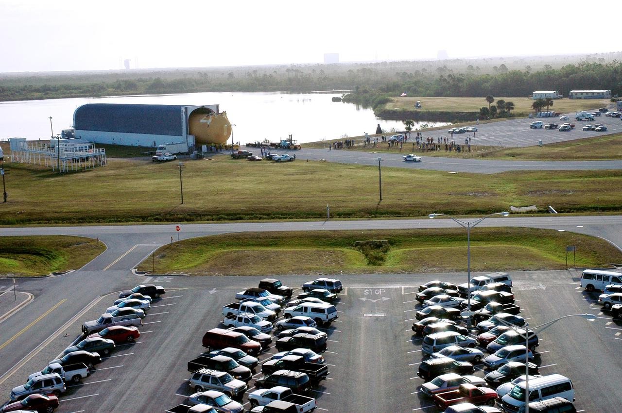
KENNEDY SPACE CENTER, FLA. - Viewed from the top of the Launch Control Center, the newly redesigned External Tank is seen moving out of NASA’s specially designed barge, Pegasus, which delivered it from the Michoud Assembly Facility in New Orleans. The tank is being transferred to the Vehicle Assembly Building. In the transfer aisle of the VAB, the tank will be raised from a horizontal to a vertical position, then lifted high up into a storage cell, or “checkout cell,” where it will undergo inspections of the mechanical, electrical and thermal protection systems. New processing activities resulting from re-design of the tank include inspection of the bipod heater and External Tank separation camera, which includes charging the camera batteries. The tank will be then prepared for mating to the Solid Rocket Boosters. When preparations are complete, the tank will be lifted from the checkout cell, moved across the transfer aisle and into High Bay 1, where it will be lowered and attached to the boosters, which are sitting on the Mobile Launch Platform. The tank is designated for the Return to Flight mission, STS-114, targeted for a launch opportunity beginning in May. The seven-member Discovery crew will fly to the International Space Station primarily to test and evaluate new procedures for flight safety, including Space Shuttle inspection and repair techniques.
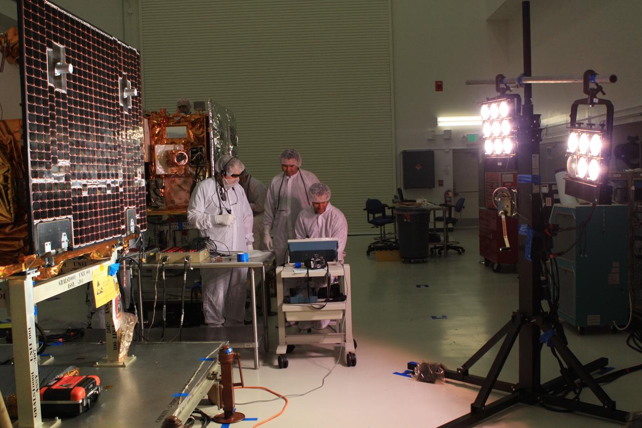
CAPE CANAVERAL, Fla. -- Lockheed Martin technicians in Astrotech Space Operation's payload processing facility in Titusville, Fla., test the solar arrays on NASA's Gravity Recovery and Interior Laboratory-A, or GRAIL-A, spacecraft to ensure that they will function as planned during the mission. The electrical power subsystem on each of GRAIL's twin spacecraft includes two solar arrays and a lithium ion battery. Each solar array is capable of producing no less than 700 watts. They will be deployed shortly after separation from the launch vehicle and remain fixed throughout the mission. GRAIL will fly in tandem orbits around the moon for several months to measure its gravity field. GRAIL's primary science objectives are to determine the structure of the lunar interior, from crust to core, and to advance understanding of the thermal evolution of the moon. Launch aboard a United Launch Alliance Delta II rocket from Space Launch Complex 17B on Cape Canaveral Air Force Station is scheduled for Sept. 8. For more information, visit http://www.nasa.gov/grail. Photo credit: NASA/Frankie Martin
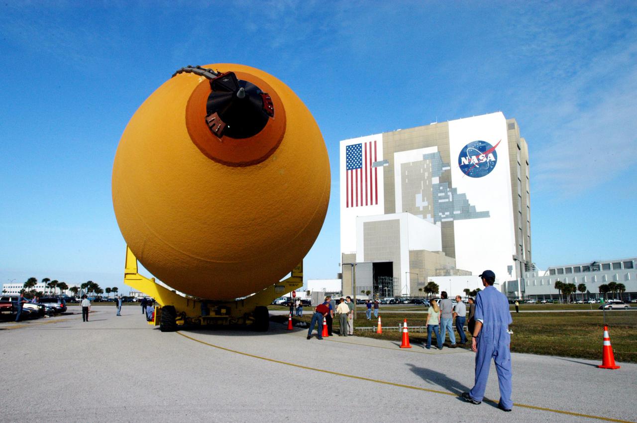
KENNEDY SPACE CENTER, FLA. - The newly redesigned External Tank slowly moves toward the Vehicle Assembly Building, seen at right. The tank arrived Jan. 5 after a 900-mile sea voyage aboard NASA’s specially designed barge, Pegasus, from the Michoud Assembly Facility in New Orleans. In the transfer aisle of the VAB, the tank will be raised from a horizontal to a vertical position, then lifted high up into a storage cell, or “checkout cell,” where it will undergo inspections of the mechanical, electrical and thermal protection systems. New processing activities resulting from re-design of the tank include inspection of the bipod heater and External Tank separation camera, which includes charging the camera batteries. The tank will be then prepared for mating to the Solid Rocket Boosters. When preparations are complete, the tank will be lifted from the checkout cell, moved across the transfer aisle and into High Bay 1, where it will be lowered and attached to the boosters, which are sitting on the Mobile Launch Platform. The tank is designated for the Return to Flight mission, STS-114, targeted for a launch opportunity beginning in May. The seven-member Discovery crew will fly to the International Space Station primarily to test and evaluate new procedures for flight safety, including Space Shuttle inspection and repair techniques.
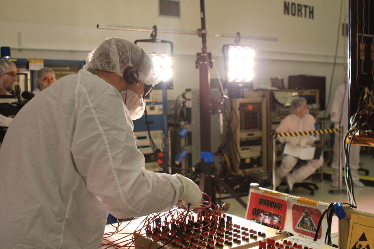
CAPE CANAVERAL, Fla. -- A Lockheed Martin technician in Astrotech Space Operation's payload processing facility in Titusville, Fla., tests the solar arrays on NASA's Gravity Recovery and Interior Laboratory-A, or GRAIL-A, spacecraft to ensure that they will function as planned during the mission. The electrical power subsystem on each of GRAIL's twin spacecraft includes two solar arrays and a lithium ion battery. Each solar array is capable of producing no less than 700 watts. They will be deployed shortly after separation from the launch vehicle and remain fixed throughout the mission. GRAIL will fly in tandem orbits around the moon for several months to measure its gravity field. GRAIL's primary science objectives are to determine the structure of the lunar interior, from crust to core, and to advance understanding of the thermal evolution of the moon. Launch aboard a United Launch Alliance Delta II rocket from Space Launch Complex 17B on Cape Canaveral Air Force Station is scheduled for Sept. 8. For more information, visit http://www.nasa.gov/grail. Photo credit: NASA/Frankie Martin
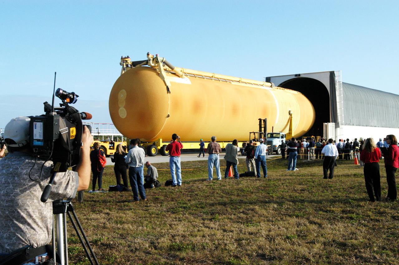
KENNEDY SPACE CENTER, FLA. - Media view the newly redesigned External Tank as it is off-loaded from the barge that carried it from the Michoud Assembly Facility in New Orleans. The tank is being transported to the Vehicle Assembly Building. The tank arrived Jan. 5 after a 900-mile sea voyage aboard NASA’s specially designed barge, Pegasus, from the Michoud Assembly Facility in New Orleans. In the transfer aisle of the VAB, the tank will be raised from a horizontal to a vertical position, then lifted high up into a storage cell, or “checkout cell,” where it will undergo inspections of the mechanical, electrical and thermal protection systems. New processing activities resulting from re-design of the tank include inspection of the bipod heater and External Tank separation camera, which includes charging the camera batteries. The tank will be then prepared for mating to the Solid Rocket Boosters. When preparations are complete, the tank will be lifted from the checkout cell, moved across the transfer aisle and into High Bay 1, where it will be lowered and attached to the boosters, which are sitting on the Mobile Launch Platform. The tank is designated for the Return to Flight mission, STS-114, targeted for a launch opportunity beginning in May. The seven-member Discovery crew will fly to the International Space Station primarily to test and evaluate new procedures for flight safety, including Space Shuttle inspection and repair techniques.