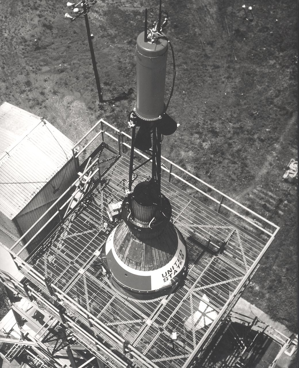
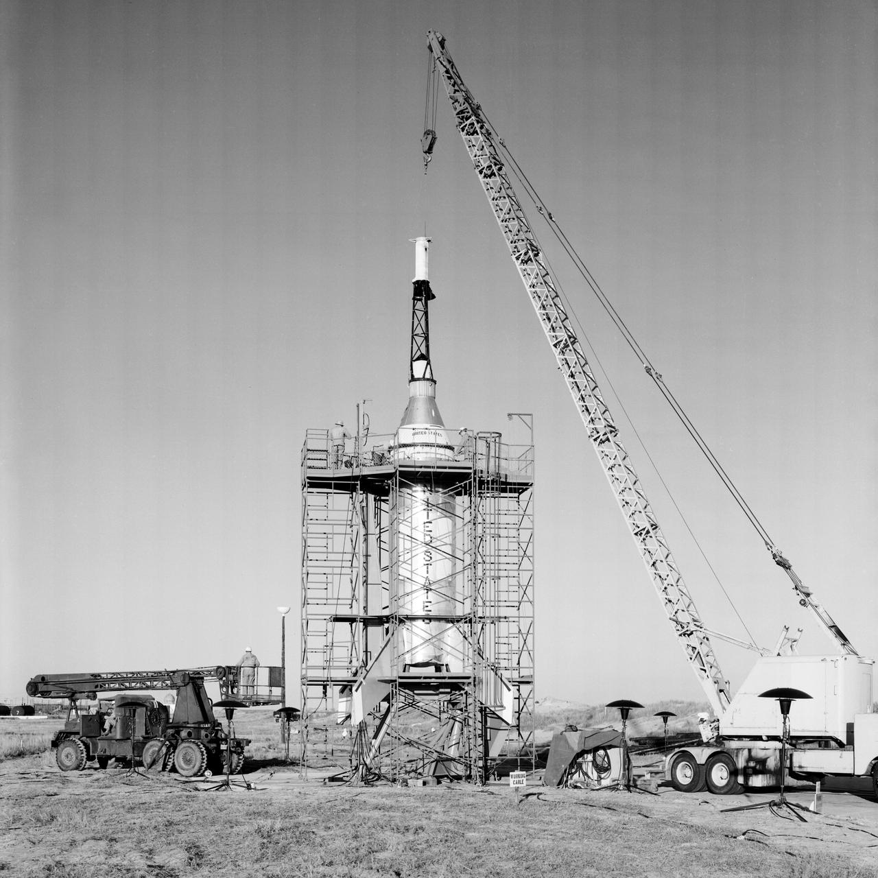
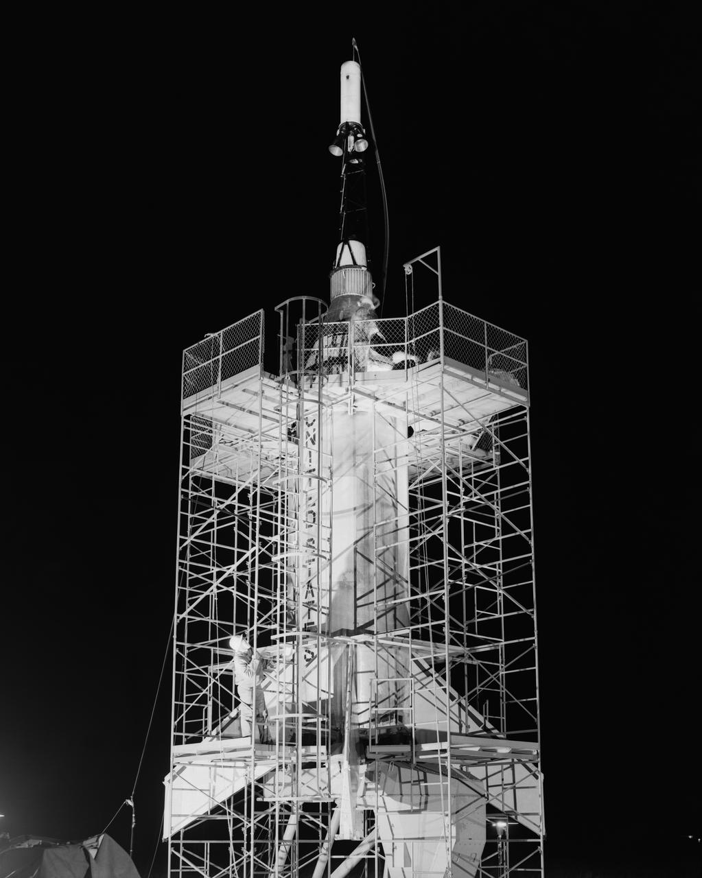
This photograph depicts installation of the Mercury capsule and escape system on top of a booster prior to test firing of the Mercury-Redstone launch vehicle at the Marshall Space Flight Center.

Caption: Off the pad abort shot at Wallops using Langley PARD designed full scale capsule with Recruit rocket and extended skirt main parachute. Shows sequential images of launch and capsule splashdown.

A Mercury capsule is mounted inside the Altitude Wind Tunnel for a test of its escape tower rockets at the National Aeronautics and Space Administration (NASA) Lewis Research Center. In October 1959 NASA’s Space Task Group allocated several Project Mercury assignments to Lewis. The Altitude Wind Tunnel was quickly modified so that its 51-foot diameter western leg could be used as a test chamber. The final round of tests in the Altitude Wind Tunnel sought to determine if the smoke plume from the capsule’s escape tower rockets would shroud or compromise the spacecraft. The escape tower, a 10-foot steel rig with three small rockets, was attached to the nose of the Mercury capsule. It could be used to jettison the astronaut and capsule to safety in the event of a launch vehicle malfunction on the pad or at any point prior to separation from the booster. Once actuated, the escape rockets would fire, and the capsule would be ejected away from the booster. After the capsule reached its apex of about 2,500 feet, the tower, heatshield, retropackage, and antenna would be ejected and a drogue parachute would be released. Flight tests of the escape system were performed at Wallops Island as part of the series of Little Joe launches. Although the escape rockets fired prematurely on Little Joe’s first attempt in August 1959, the January 1960 follow-up was successful.

S62-04976 (31 Aug. 1962) --- Artist concept of the Mercury capsule with its launch escape system. Photo credit: NASA
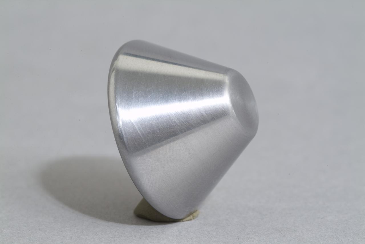
CEV (Crew Escape Vehicle) capsule Balistic Range testing to examine static and dynamic stability characteristics (at the Hypervelocity Free-Flight Facility) HFF
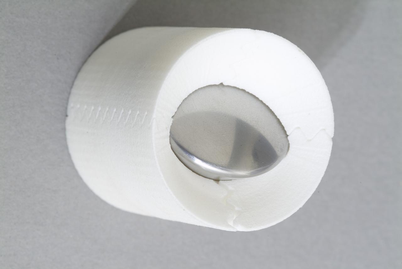
CEV (Crew Escape Vehicle) capsule Balistic Range testing to examine static and dynamic stability characteristics (at the Hypervelocity Free-Flight Facility) HFF
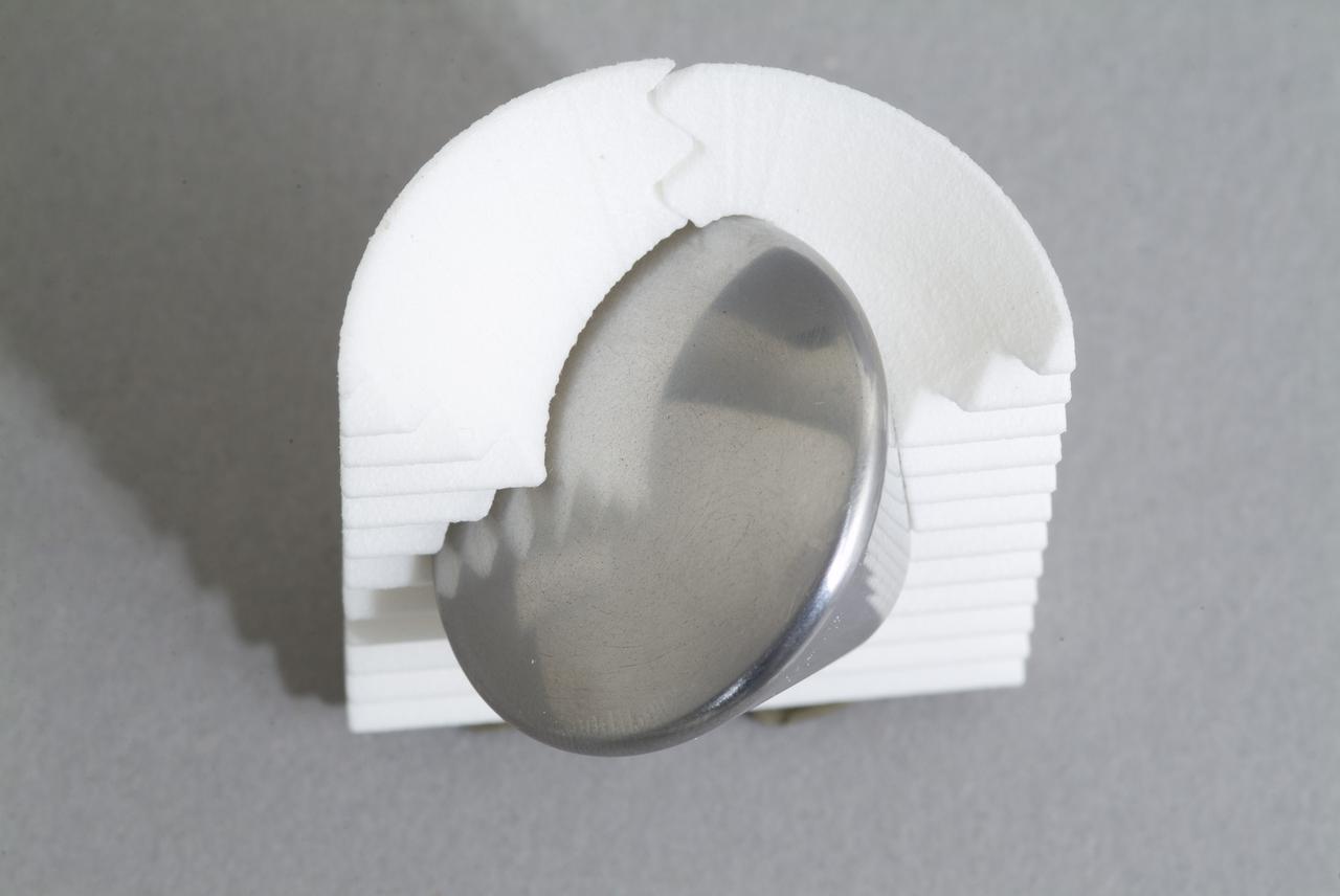
CEV (Crew Escape Vehicle) capsule Balistic Range testing to examine static and dynamic stability characteristics (at the Hypervelocity Free-Flight Facility) HFF
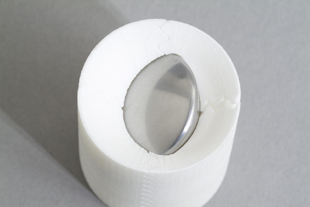
CEV (Crew Escape Vehicle) capsule Balistic Range testing to examine static and dynamic stability characteristics (at the Hypervelocity Free-Flight Facility) HFF
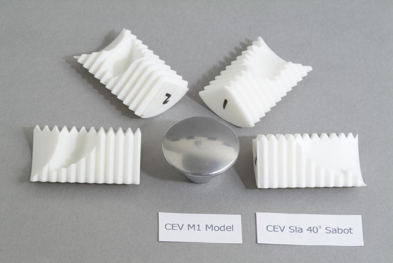
CEV (Crew Escape Vehicle) capsule Balistic Range testing to examine static and dynamic stability characteristics (at the Hypervelocity Free-Flight Facility) HFF
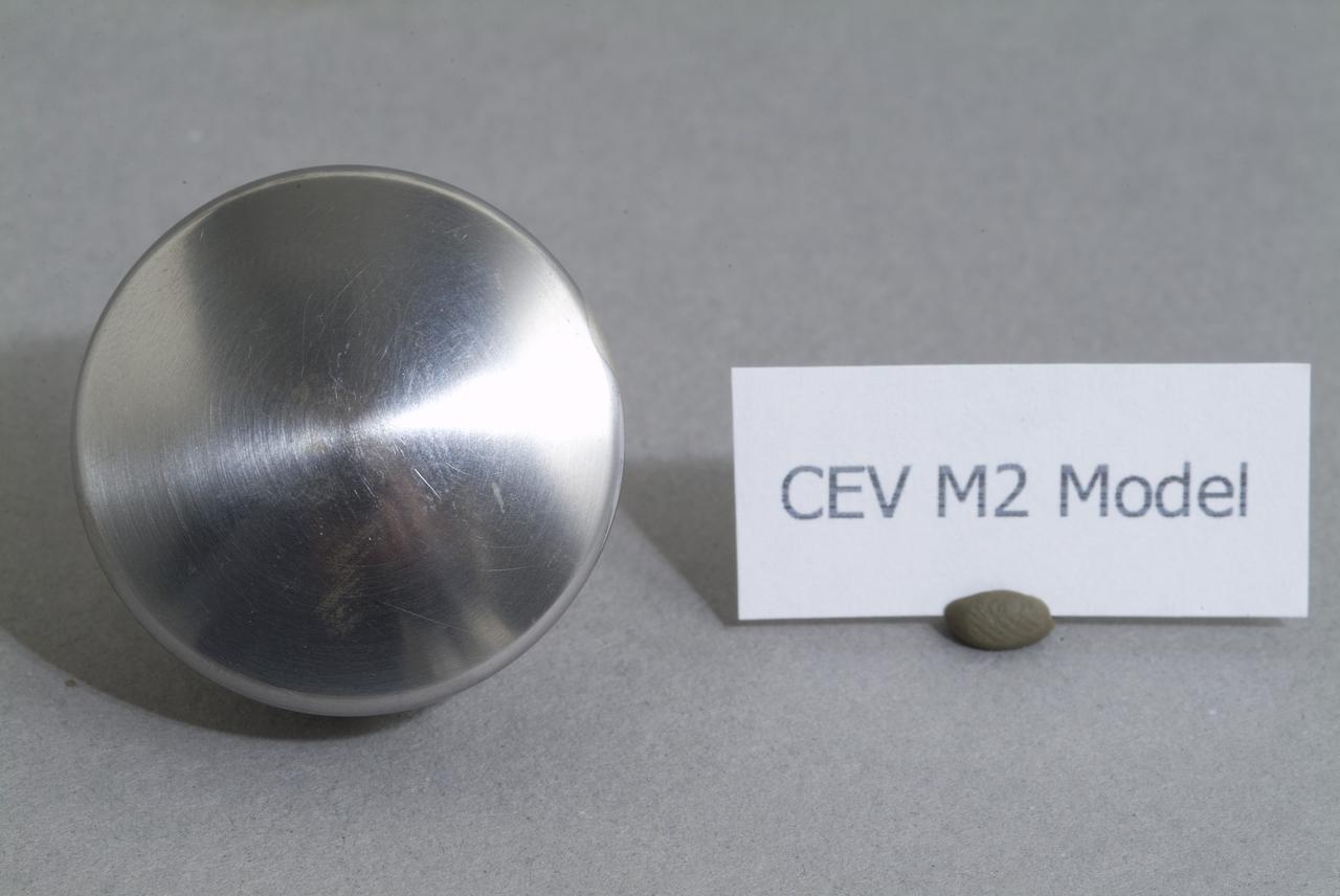
CEV (Crew Escape Vehicle) capsule Balistic Range testing to examine static and dynamic stability characteristics (at the Hypervelocity Free-Flight Facility) HFF
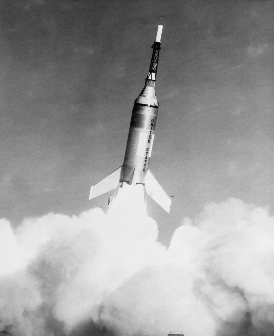
G61-00030 (4 Nov. 1959) --- Launch of Little Joe-2 from Wallops Island carrying Mercury spacecraft test article. The suborbital test flight of the Mercury capsule was to test the escape system. Vehicle functioned perfectly, but escape rocket ignited several seconds too late. Photo credit: NASA

B60-00364 (4 Nov. 1959) --- Launch of Little Joe-2 from Wallops Island carrying Mercury spacecraft test article. The suborbital test flight of the Mercury capsule was to test the escape system. Vehicle functioned perfectly, but escape rocket ignited several seconds too late. Photo credit: NASA

This photograph shows the installation of a Mercury capsule and escape system on top of a booster prior to test firing of the Mercury-Redstone at Marshall Space Flight Center's (MSFC's) Redstone Test Stand. Assembled by MSFC, the Mercury-Redstone was designed to place a marned space capsule in orbital flight around the Earth and recover both safely.

CEV (Crew Escape Vehicle) capsule Balistic Range testing to examine static and dynamic stability characteristics (at the Hypervelocity Free-Flight Facility) HFF - Bon Bowling machining sabot to find dimensions
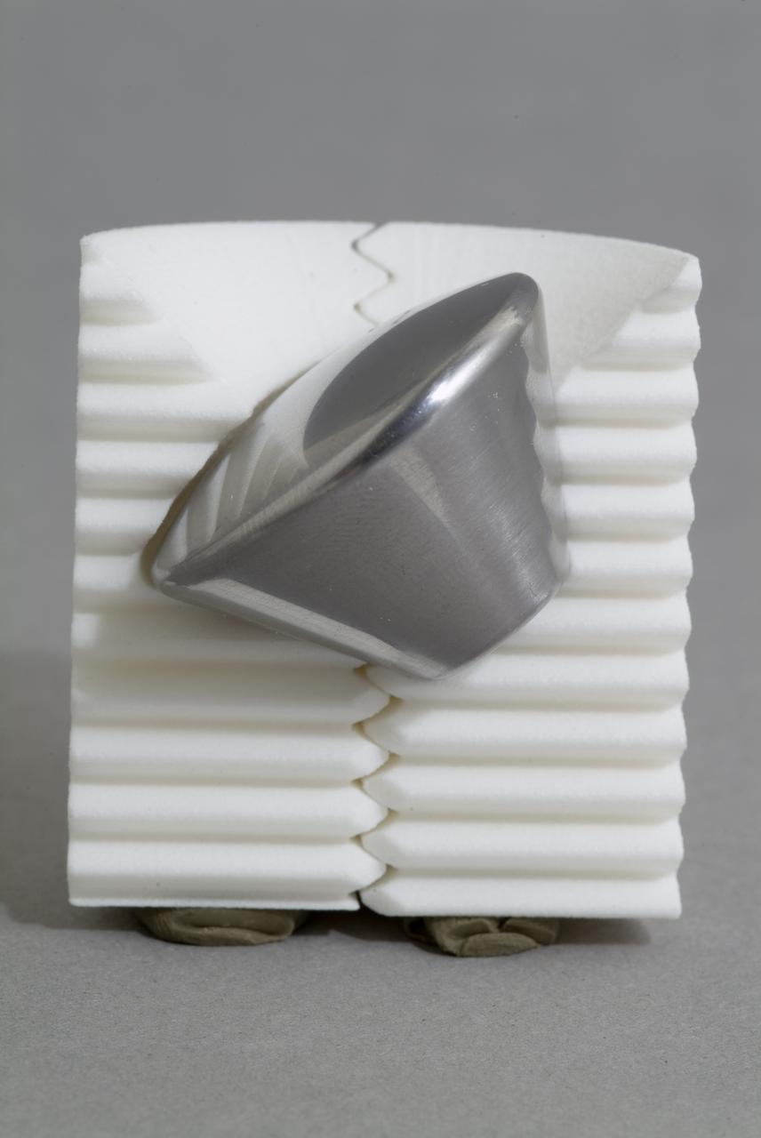
CEV (Crew Escape Vehicle) capsule Balistic Range testing to examine static and dynamic stability characteristics (at the Hypervelocity Free-Flight Facility) HFF - model M-1 in 40 degree initial launch angle with sabot
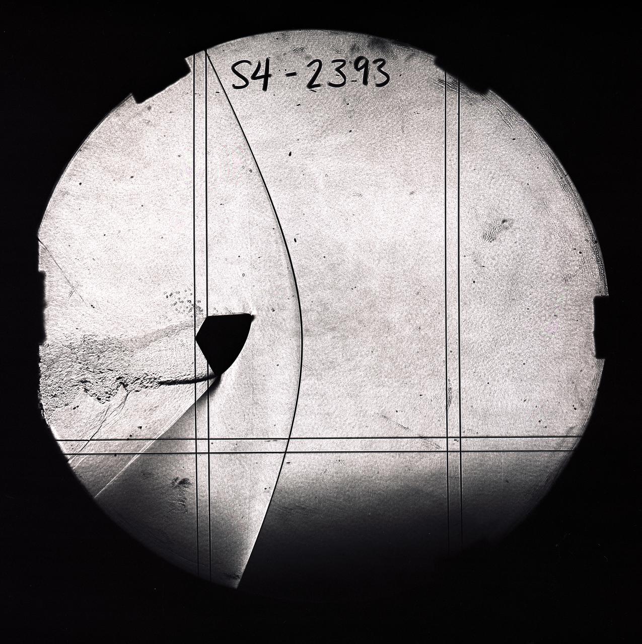
CEV (Crew Escape Vehicle) capsule Balistic Range testing to examine static and dynamic stability characteristics (at the Hypervelocity Free-Flight Facility) HFF - scans of shadowgraphs from 8x10 film images
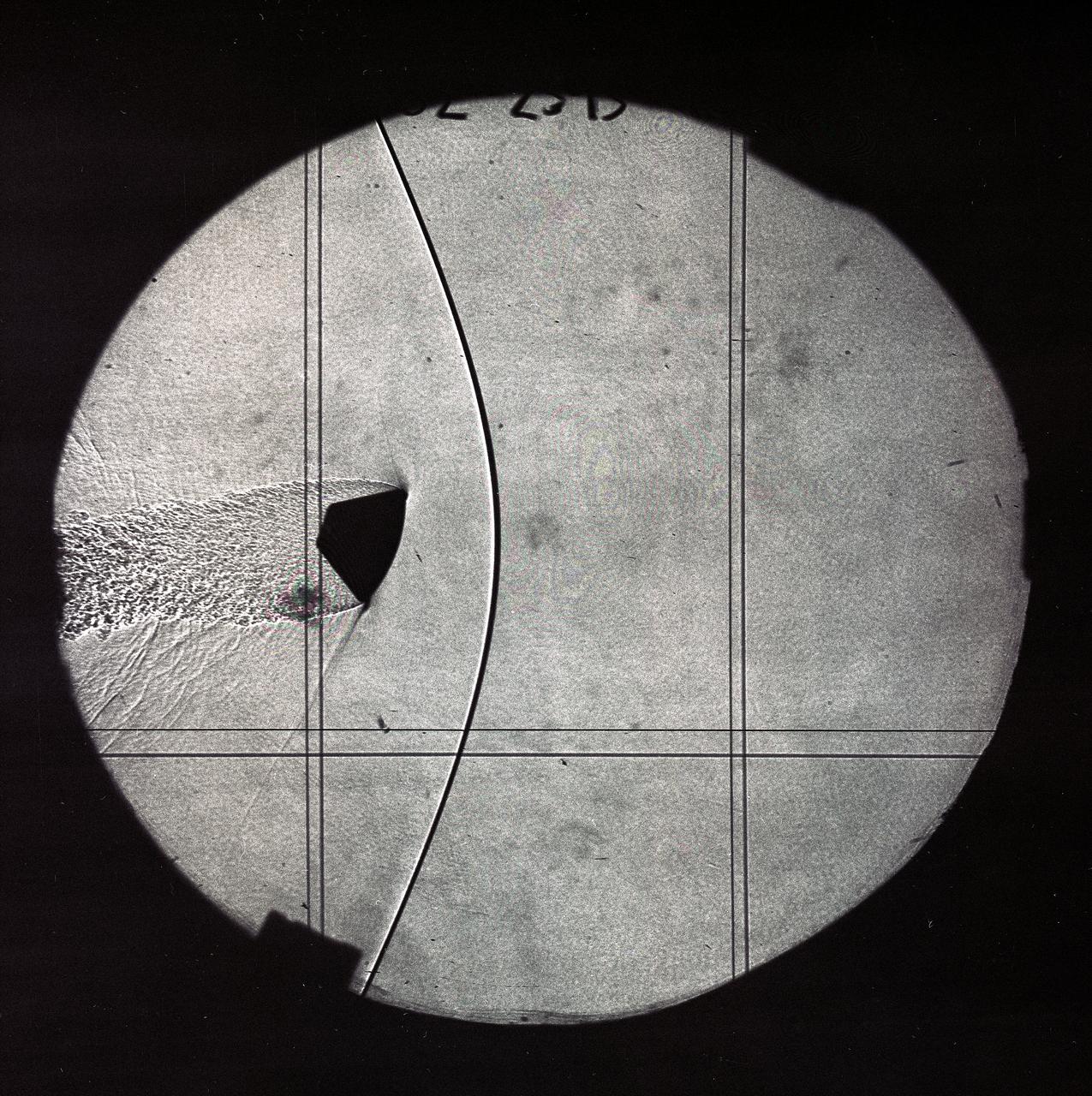
CEV (Crew Escape Vehicle) capsule Balistic Range testing to examine static and dynamic stability characteristics (at the Hypervelocity Free-Flight Facility) HFF - scans of shadowgraphs from 8x10 film images
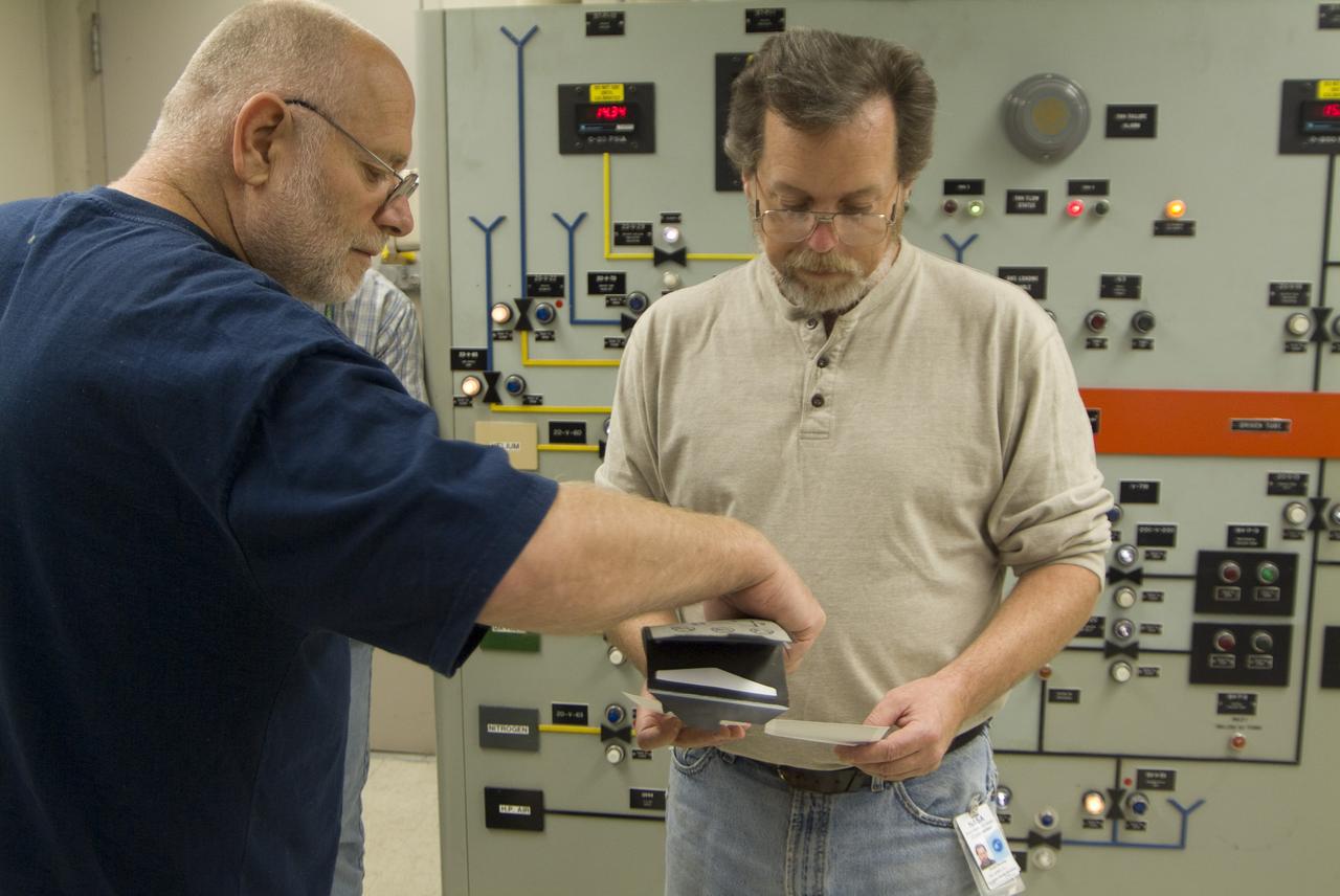
CEV (Crew Escape Vehicle) capsule Balistic Range testing to examine static and dynamic stability characteristics (at the Hypervelocity Free-Flight Facility) HFF - Don Holt (L) & Don Bowling (r) in control room examining poloroids
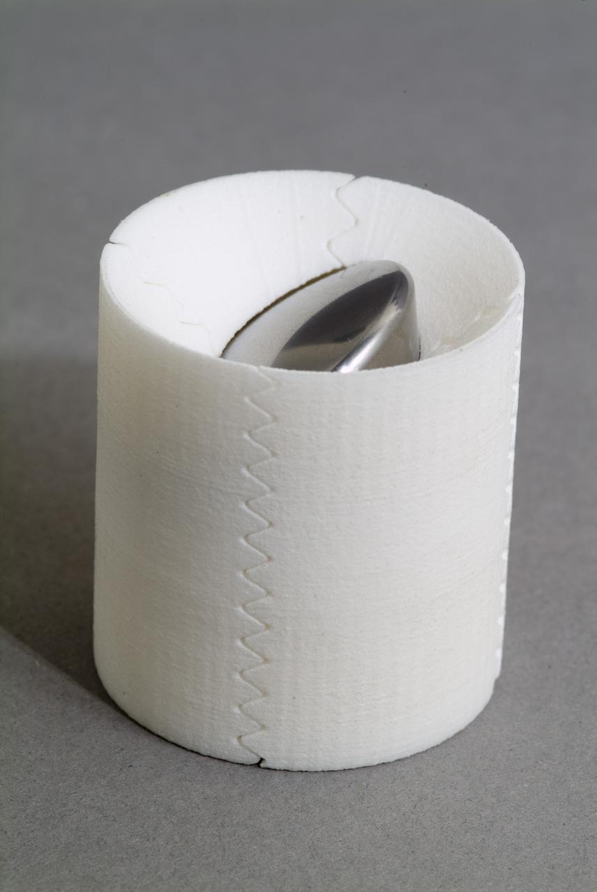
CEV (Crew Escape Vehicle) capsule Balistic Range testing to examine static and dynamic stability characteristics (at the Hypervelocity Free-Flight Facility) HFF - model M-1 in 40 degree initial launch angle with sabot
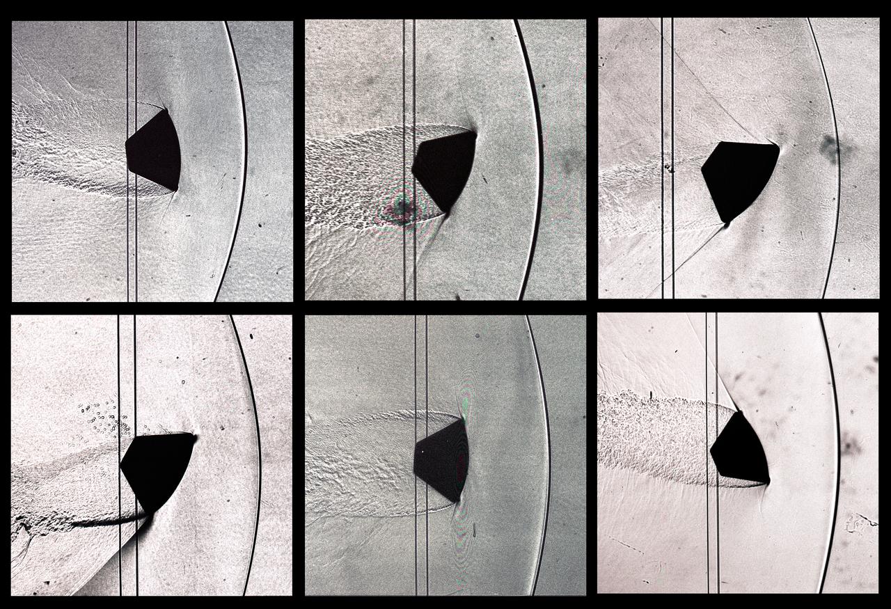
CEV (Crew Escape Vehicle) capsule Balistic Range testing to examine static and dynamic stability characteristics (at the Hypervelocity Free-Flight Facility) HFF - scans of shadowgraphs from 8x10 film images
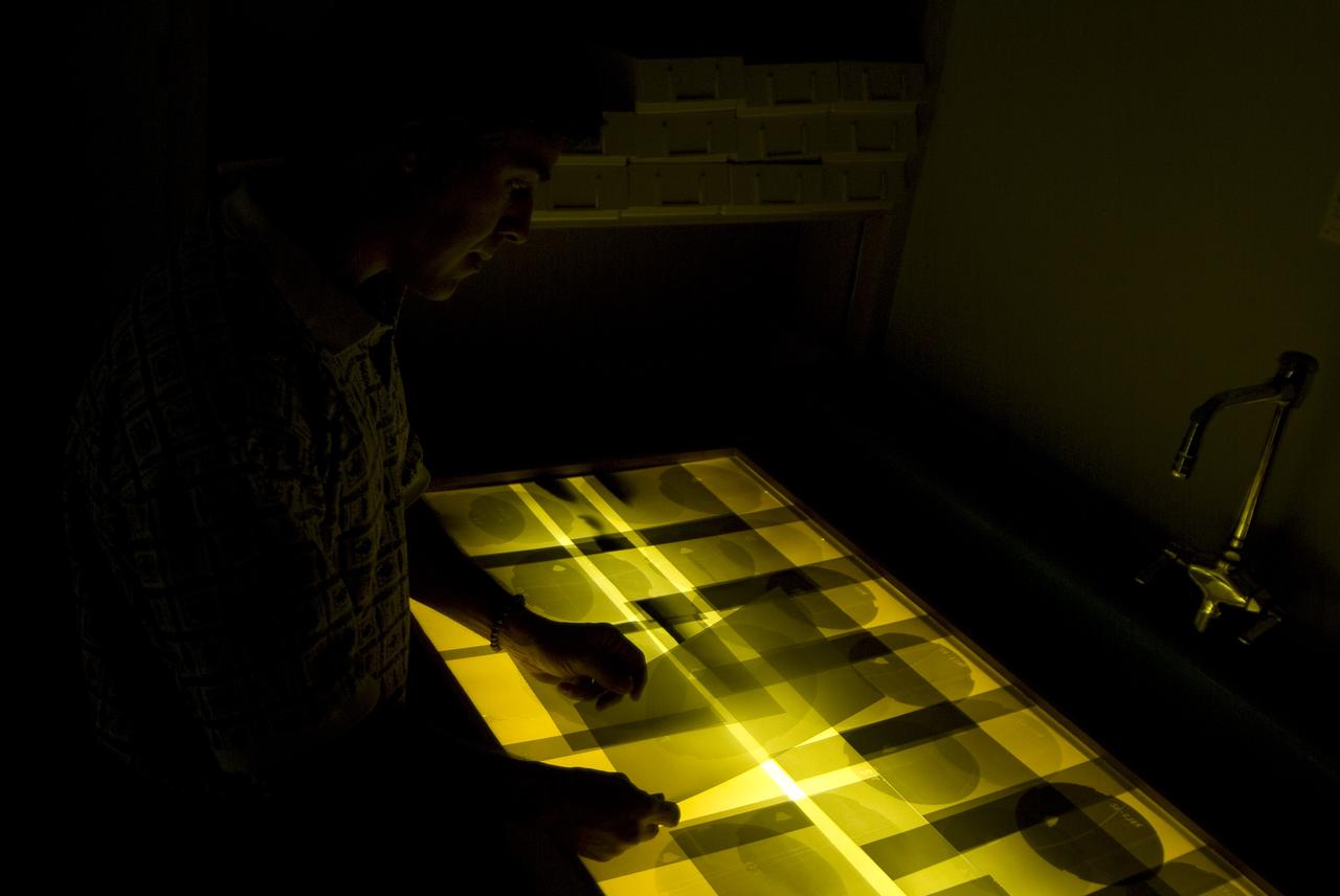
CEV (Crew Escape Vehicle) capsule Balistic Range testing to examine static and dynamic stability characteristics (at the Hypervelocity Free-Flight Facility) HFF - Chuck Cornelison viewing 8x10 shadowgraph images
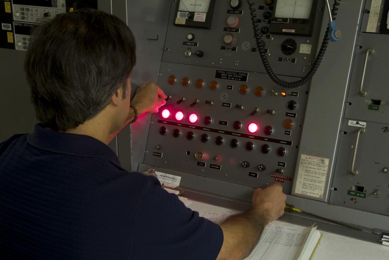
CEV (Crew Escape Vehicle) capsule Balistic Range testing to examine static and dynamic stability characteristics (at the Hypervelocity Free-Flight Facility) HFF Chuck Cornelison operating 'Firing' control pannel
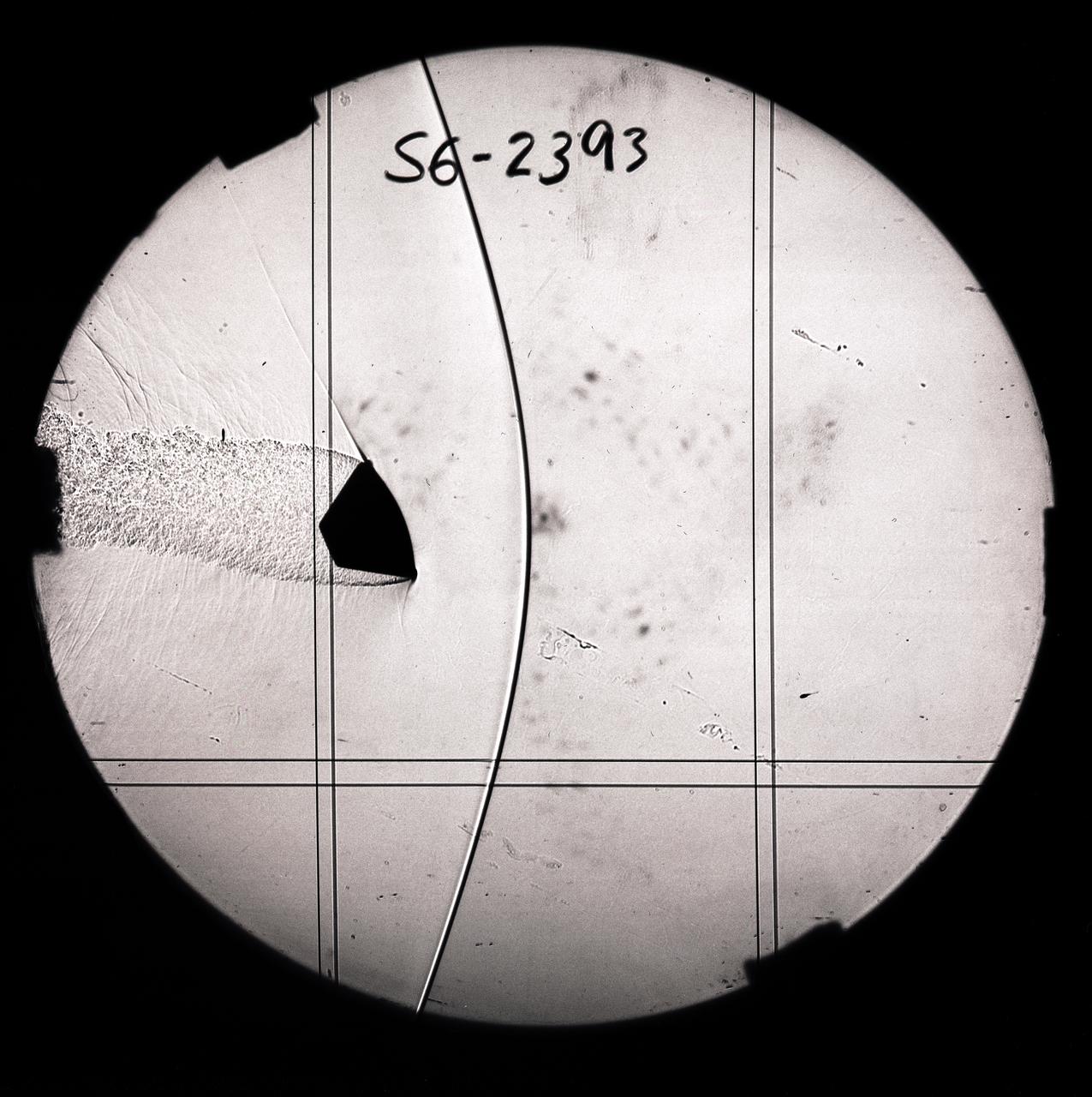
CEV (Crew Escape Vehicle) capsule Balistic Range testing to examine static and dynamic stability characteristics (at the Hypervelocity Free-Flight Facility) HFF - scans of shadowgraphs from 8x10 film images
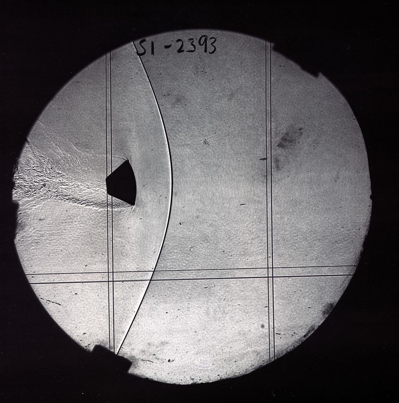
CEV (Crew Escape Vehicle) capsule Balistic Range testing to examine static and dynamic stability characteristics (at the Hypervelocity Free-Flight Facility) HFF - scans of shadowgraphs from 8x10 film images
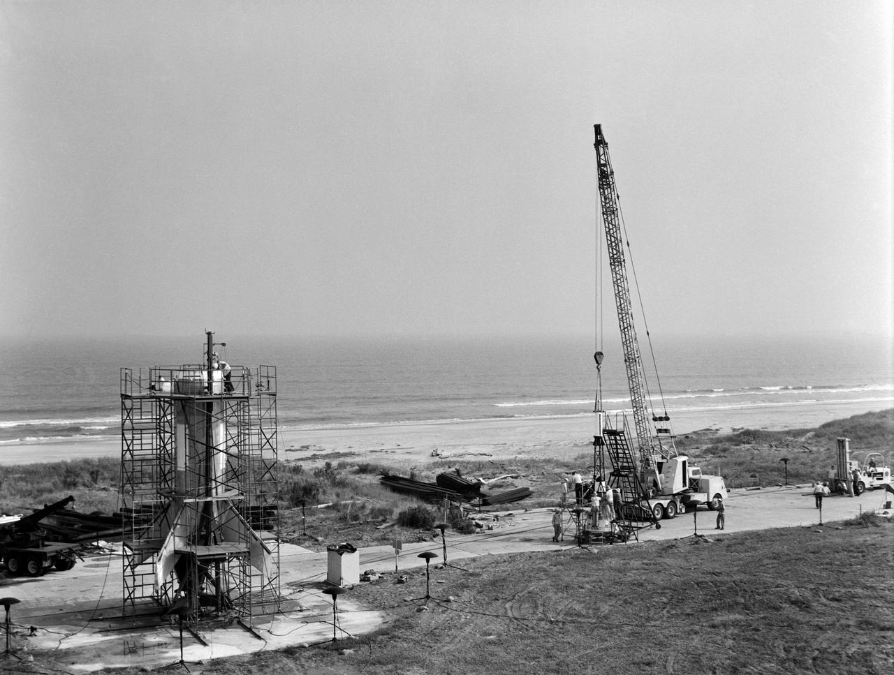
Technicians attach the escape tower to the Mercury capsule prior to assembly with Little Joe launcher, August 20, 1959. Joseph Shortal describe this as follows (vol. 3., p. 33): The escape tower and rocket motors were taken from the Mercury capsule production. The tower is shown being attached to the capsule.... The escape rocket was a Grand Central 1-KS-52000 motor with three canted nozzles. The tower-jettison motor was an Atlantic Research Corp. 1.4-KS-785 motor. This was the same design tested in a beach abort test...and had the offset thrust line as used in the beach abort test to insure that the capsule would get away from the booster in an emergency. The escape system weighed 1,015 pounds, including 236 pounds of ballast for stability. The Little Joe booster was assembled at Wallops on its special launcher in a vertical attitude. It is shown in the on the left with the work platform in place. The launcher was located on a special concrete slab in Launching Area 1. The capsule was lowered onto the booster by crane.... After the assembly was completed, the scaffolding was disassembled and the launcher pitched over to its normal launch angle of 80 degrees.... Little Joe had a diameter of 80 inches and an overall length, including the capsule and escape tower of 48 feet. The total weight at launch was about 43,000 pounds. The overall span of the stabilizing fins was 21.3 feet. Although in comparison with the overall Mercury Project, Little Joe was a simple undertaking, the fact that an attempt was made to condense a normal two-year project into a 6-month one with in house labor turned it into a major undertaking for Langley. -- Published in Joseph A. Shortal, History of Wallops Station: Origins and Activities Through 1949, (Wallops Island, VA: National Aeronautics and Space Administration, Wallops Station, nd), Comment Edition.
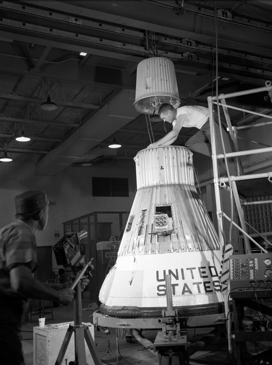
Technicians adjust the rocket motor during the attachment of the escape tower to the Mercury capsule prior to assembly with Little Joe launcher, August 20, 1959. Joseph Shortal wrote (vol. 3., p. 33): The escape tower and rocket motors were taken from the Mercury capsule production. The tower is shown being attached to the capsule.... The escape rocket was a Grand Central 1-KS-52000 motor with three canted nozzles. The tower-jettison motor was an Atlantic Research Corp. 1.4-KS-785 motor. This was the same design tested in a beach abort test...and had the offset thrust line as used in the beach abort test to insure that the capsule would get away from the booster in an emergency. The escape system weighed 1,015 pounds, including 236 pounds of ballast for stability. The Little Joe booster was assembled at Wallops on its special launcher in a vertical attitude. It is shown in the on the left with the work platform in place. The launcher was located on a special concrete slab in Launching Area 1. The capsule was lowered onto the booster by crane.... After the assembly was completed, the scaffolding was disassembled and the launcher pitched over to its normal launch angle of 80 degrees.... Little Joe had a diameter of 80 inches and an overall length, including the capsule and escape tower of 48 feet. The total weight at launch was about 43,000 pounds. The overall span of the stabilizing fins was 21.3 feet. Although in comparison with the overall Mercury Project, Little Joe was a simple undertaking, the fact that an attempt was made to condense a normal two-year project into a 6-month one with in house labor turned it into a major undertaking for Langley. -- Published in Joseph A. Shortal, History of Wallops Station: Origins and Activities Through 1949, (Wallops Island, VA: National Aeronautics and Space Administration, Wallops Station, nd), Comment Edition.
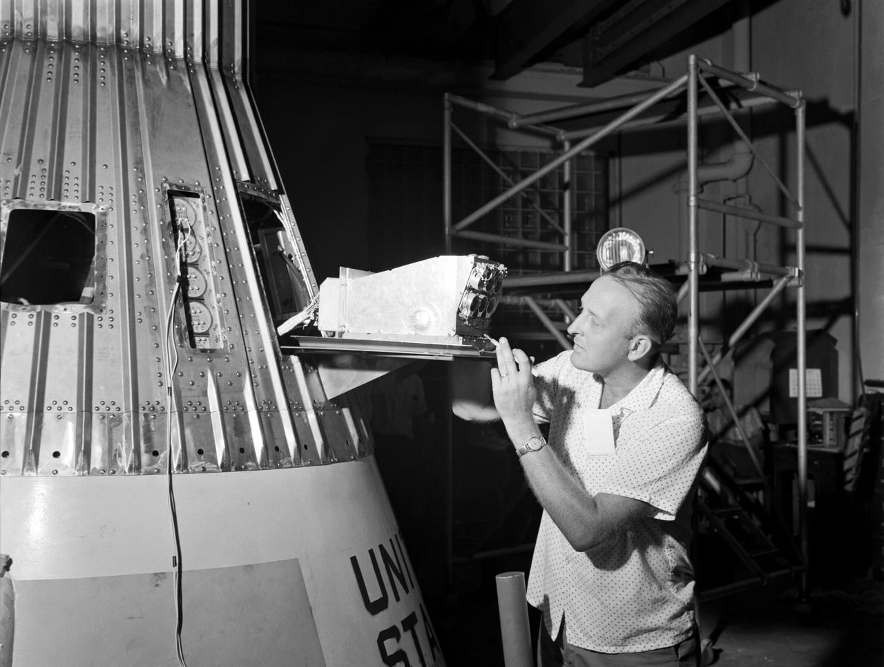
Technicians adjust the rocket motor during the attachment of the escape tower to the Mercury capsule prior to assembly with Little Joe launcher, August 20, 1959. Joseph Shortal wrote (vol. 3., p. 33): The escape tower and rocket motors were taken from the Mercury capsule production. The tower is shown being attached to the capsule.... The escape rocket was a Grand Central 1-KS-52000 motor with three canted nozzles. The tower-jettison motor was an Atlantic Research Corp. 1.4-KS-785 motor. This was the same design tested in a beach abort test...and had the offset thrust line as used in the beach abort test to insure that the capsule would get away from the booster in an emergency. The escape system weighed 1,015 pounds, including 236 pounds of ballast for stability. The Little Joe booster was assembled at Wallops on its special launcher in a vertical attitude. It is shown in the on the left with the work platform in place. The launcher was located on a special concrete slab in Launching Area 1. The capsule was lowered onto the booster by crane.... After the assembly was completed, the scaffolding was disassembled and the launcher pitched over to its normal launch angle of 80 degrees.... Little Joe had a diameter of 80 inches and an overall length, including the capsule and escape tower of 48 feet. The total weight at launch was about 43,000 pounds. The overall span of the stabilizing fins was 21.3 feet. Although in comparison with the overall Mercury Project, Little Joe was a simple undertaking, the fact that an attempt was made to condense a normal two-year project into a 6-month one with in house labor turned it into a major undertaking for Langley. -- Published in Joseph A. Shortal, History of Wallops Station: Origins and Activities Through 1949, (Wallops Island, VA: National Aeronautics and Space Administration, Wallops Station, nd), Comment Edition.
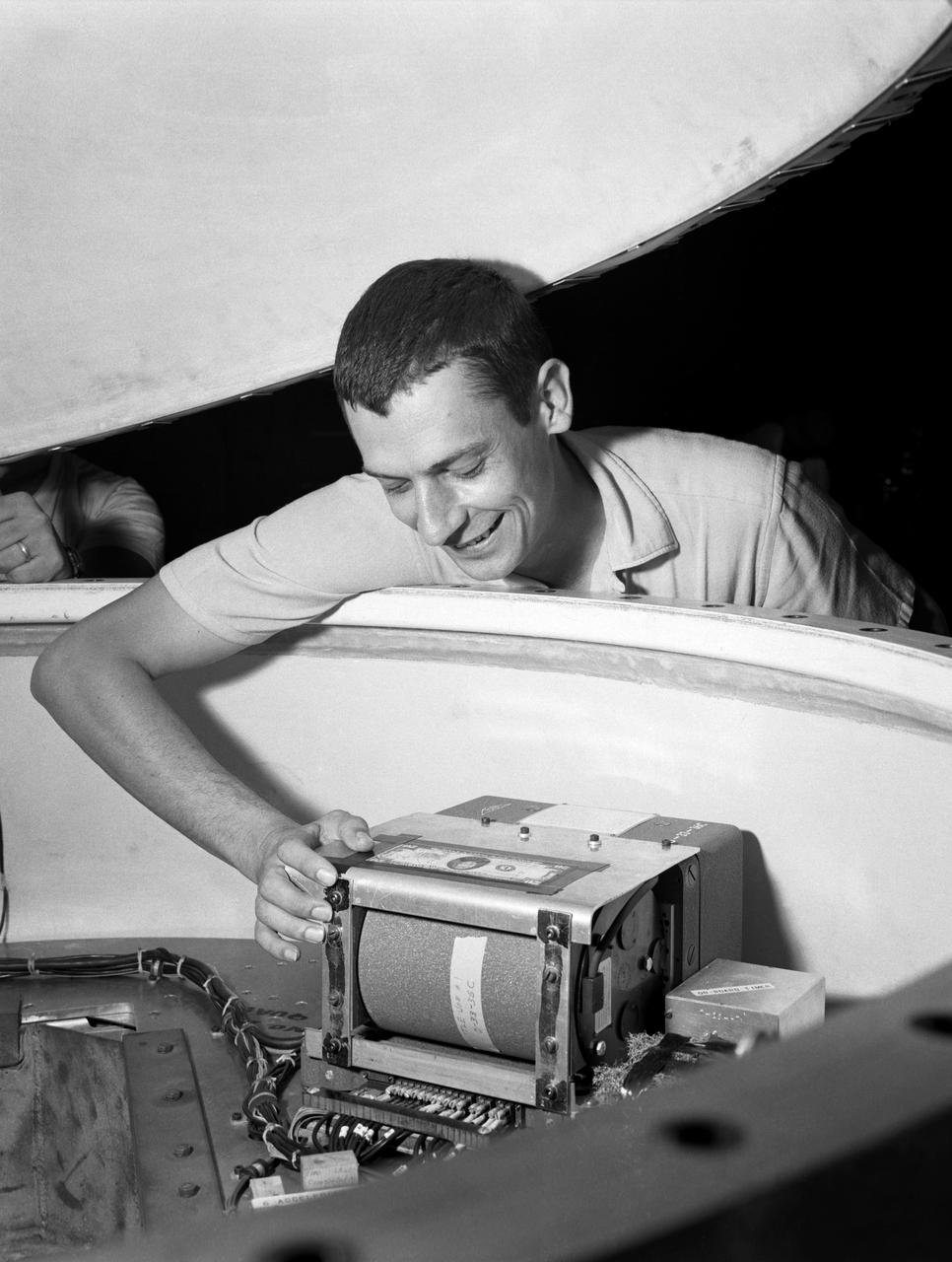
Technicians adjust the rocket motor during the attachment of the escape tower to the Mercury capsule prior to assembly with Little Joe launcher, August 20, 1959. Joseph Shortal wrote (vol. 3., p. 33): The escape tower and rocket motors were taken from the Mercury capsule production. The tower is shown being attached to the capsule.... The escape rocket was a Grand Central 1-KS-52000 motor with three canted nozzles. The tower-jettison motor was an Atlantic Research Corp. 1.4-KS-785 motor. This was the same design tested in a beach abort test...and had the offset thrust line as used in the beach abort test to insure that the capsule would get away from the booster in an emergency. The escape system weighed 1,015 pounds, including 236 pounds of ballast for stability. The Little Joe booster was assembled at Wallops on its special launcher in a vertical attitude. It is shown in the on the left with the work platform in place. The launcher was located on a special concrete slab in Launching Area 1. The capsule was lowered onto the booster by crane.... After the assembly was completed, the scaffolding was disassembled and the launcher pitched over to its normal launch angle of 80 degrees.... Little Joe had a diameter of 80 inches and an overall length, including the capsule and escape tower of 48 feet. The total weight at launch was about 43,000 pounds. The overall span of the stabilizing fins was 21.3 feet. Although in comparison with the overall Mercury Project, Little Joe was a simple undertaking, the fact that an attempt was made to condense a normal two-year project into a 6-month one with in house labor turned it into a major undertaking for Langley. -- Published in Joseph A. Shortal, History of Wallops Station: Origins and Activities Through 1949, (Wallops Island, VA: National Aeronautics and Space Administration, Wallops Station, nd), Comment Edition.
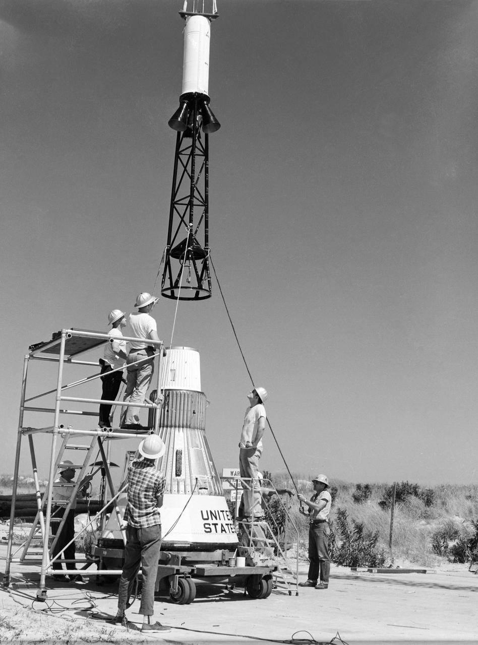
Technicians attach the escape tower to the Mercury capsule prior to assembly with Little Joe launcher, August 20, 1959. Joseph Shortal describe this as follows (vol. 3., p. 33): The escape tower and rocket motors were taken from the Mercury capsule production. The tower is shown being attached to the capsule.... The escape rocket was a Grand Central 1-KS-52000 motor with three canted nozzles. The tower-jettison motor was an Atlantic Research Corp. 1.4-KS-785 motor. This was the same design tested in a beach abort test...and had the offset thrust line as used in the beach abort test to insure that the capsule would get away from the booster in an emergency. The escape system weighed 1,015 pounds, including 236 pounds of ballast for stability. The Little Joe booster was assembled at Wallops on its special launcher in a vertical attitude. It is shown in the on the left with the work platform in place. The launcher was located on a special concrete slab in Launching Area 1. The capsule was lowered onto the booster by crane.... After the assembly was completed, the scaffolding was disassembled and the launcher pitched over to its normal launch angle of 80 degrees.... Little Joe had a diameter of 80 inches and an overall length, including the capsule and escape tower of 48 feet. The total weight at launch was about 43,000 pounds. The overall span of the stabilizing fins was 21.3 feet. Although in comparison with the overall Mercury Project, Little Joe was a simple undertaking, the fact that an attempt was made to condense a normal two-year project into a 6-month one with in house labor turned it into a major undertaking for Langley. -- Published in Joseph A. Shortal, History of Wallops Station: Origins and Activities Through 1949, (Wallops Island, VA: National Aeronautics and Space Administration, Wallops Station, nd), Comment Edition.
Technicians adjust the rocket motor during the attachment of the escape tower to the Mercury capsule prior to assembly with Little Joe launcher, August 20, 1959. Joseph Shortal wrote (vol. 3., p. 33): The escape tower and rocket motors were taken from the Mercury capsule production. The tower is shown being attached to the capsule.... The escape rocket was a Grand Central 1-KS-52000 motor with three canted nozzles. The tower-jettison motor was an Atlantic Research Corp. 1.4-KS-785 motor. This was the same design tested in a beach abort test...and had the offset thrust line as used in the beach abort test to insure that the capsule would get away from the booster in an emergency. The escape system weighed 1,015 pounds, including 236 pounds of ballast for stability. The Little Joe booster was assembled at Wallops on its special launcher in a vertical attitude. It is shown in the on the left with the work platform in place. The launcher was located on a special concrete slab in Launching Area 1. The capsule was lowered onto the booster by crane.... After the assembly was completed, the scaffolding was disassembled and the launcher pitched over to its normal launch angle of 80 degrees.... Little Joe had a diameter of 80 inches and an overall length, including the capsule and escape tower of 48 feet. The total weight at launch was about 43,000 pounds. The overall span of the stabilizing fins was 21.3 feet. Although in comparison with the overall Mercury Project, Little Joe was a simple undertaking, the fact that an attempt was made to condense a normal two-year project into a 6-month one with in house labor turned it into a major undertaking for Langley. -- Published in Joseph A. Shortal, History of Wallops Station: Origins and Activities Through 1949, (Wallops Island, VA: National Aeronautics and Space Administration, Wallops Station, nd), Comment Edition.
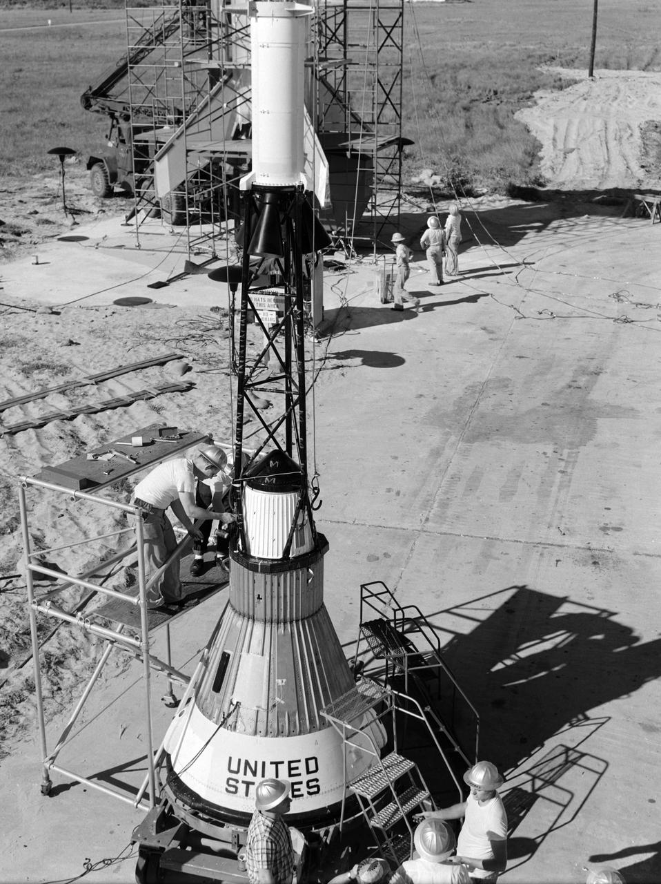
Technicians attach the escape tower to the Mercury capsule prior to assembly with Little Joe launcher, August 20, 1959. Joseph Shortal describe this as follows (vol. 3., p. 33): The escape tower and rocket motors were taken from the Mercury capsule production. The tower is shown being attached to the capsule.... The escape rocket was a Grand Central 1-KS-52000 motor with three canted nozzles. The tower-jettison motor was an Atlantic Research Corp. 1.4-KS-785 motor. This was the same design tested in a beach abort test...and had the offset thrust line as used in the beach abort test to insure that the capsule would get away from the booster in an emergency. The escape system weighed 1,015 pounds, including 236 pounds of ballast for stability. The Little Joe booster was assembled at Wallops on its special launcher in a vertical attitude. It is shown in the on the left with the work platform in place. The launcher was located on a special concrete slab in Launching Area 1. The capsule was lowered onto the booster by crane.... After the assembly was completed, the scaffolding was disassembled and the launcher pitched over to its normal launch angle of 80 degrees.... Little Joe had a diameter of 80 inches and an overall length, including the capsule and escape tower of 48 feet. The total weight at launch was about 43,000 pounds. The overall span of the stabilizing fins was 21.3 feet. Although in comparison with the overall Mercury Project, Little Joe was a simple undertaking, the fact that an attempt was made to condense a normal two-year project into a 6-month one with in house labor turned it into a major undertaking for Langley. -- Published in Joseph A. Shortal, History of Wallops Station: Origins and Activities Through 1949, (Wallops Island, VA: National Aeronautics and Space Administration, Wallops Station, nd), Comment Edition.

Technicians adjust the rocket motor during the attachment of the escape tower to the Mercury capsule prior to assembly with Little Joe launcher, August 20, 1959. Joseph Shortal wrote (vol. 3., p. 33): The escape tower and rocket motors were taken from the Mercury capsule production. The tower is shown being attached to the capsule.... The escape rocket was a Grand Central 1-KS-52000 motor with three canted nozzles. The tower-jettison motor was an Atlantic Research Corp. 1.4-KS-785 motor. This was the same design tested in a beach abort test...and had the offset thrust line as used in the beach abort test to insure that the capsule would get away from the booster in an emergency. The escape system weighed 1,015 pounds, including 236 pounds of ballast for stability. The Little Joe booster was assembled at Wallops on its special launcher in a vertical attitude. It is shown in the on the left with the work platform in place. The launcher was located on a special concrete slab in Launching Area 1. The capsule was lowered onto the booster by crane.... After the assembly was completed, the scaffolding was disassembled and the launcher pitched over to its normal launch angle of 80 degrees.... Little Joe had a diameter of 80 inches and an overall length, including the capsule and escape tower of 48 feet. The total weight at launch was about 43,000 pounds. The overall span of the stabilizing fins was 21.3 feet. Although in comparison with the overall Mercury Project, Little Joe was a simple undertaking, the fact that an attempt was made to condense a normal two-year project into a 6-month one with in house labor turned it into a major undertaking for Langley. -- Published in Joseph A. Shortal, History of Wallops Station: Origins and Activities Through 1949, (Wallops Island, VA: National Aeronautics and Space Administration, Wallops Station, nd), Comment Edition.
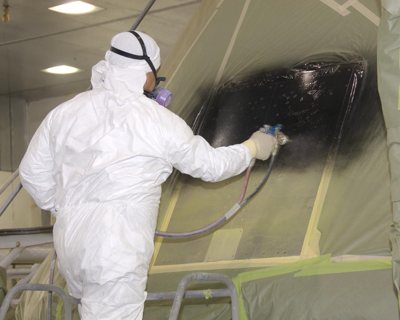
A full-scale flight-test mockup of the Constellation program's Orion crew vehicle arrived at NASA's Dryden Flight Research Center in late March 2008 to undergo preparations for the first short-range flight test of the spacecraft's astronaut escape system later that year. Engineers and technicians at NASA's Langley Research Center fabricated the structure, which precisely represents the size, outer shape and mass characteristics of the Orion space capsule. The Orion crew module mockup was ferried to NASA Dryden on an Air Force C-17. After painting in the Edwards Air Force Base paint hangar, the conical capsule was taken to Dryden for installation of flight computers, instrumentation and other electronics prior to being sent to the U.S. Army's White Sands Missile Range in New Mexico for integration with the escape system and the first abort flight test in late 2008. The tests were designed to ensure a safe, reliable method of escape for astronauts in case of an emergency.
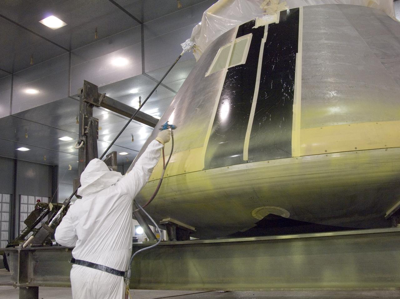
A full-scale flight-test mockup of the Constellation program's Orion crew vehicle arrived at NASA's Dryden Flight Research Center in late March 2008 to undergo preparations for the first short-range flight test of the spacecraft's astronaut escape system later that year. Engineers and technicians at NASA's Langley Research Center fabricated the structure, which precisely represents the size, outer shape and mass characteristics of the Orion space capsule. The Orion crew module mockup was ferried to NASA Dryden on an Air Force C-17. After painting in the Edwards Air Force Base paint hangar, the conical capsule was taken to Dryden for installation of flight computers, instrumentation and other electronics prior to being sent to the U.S. Army's White Sands Missile Range in New Mexico for integration with the escape system and the first abort flight test in late 2008. The tests were designed to ensure a safe, reliable method of escape for astronauts in case of an emergency.
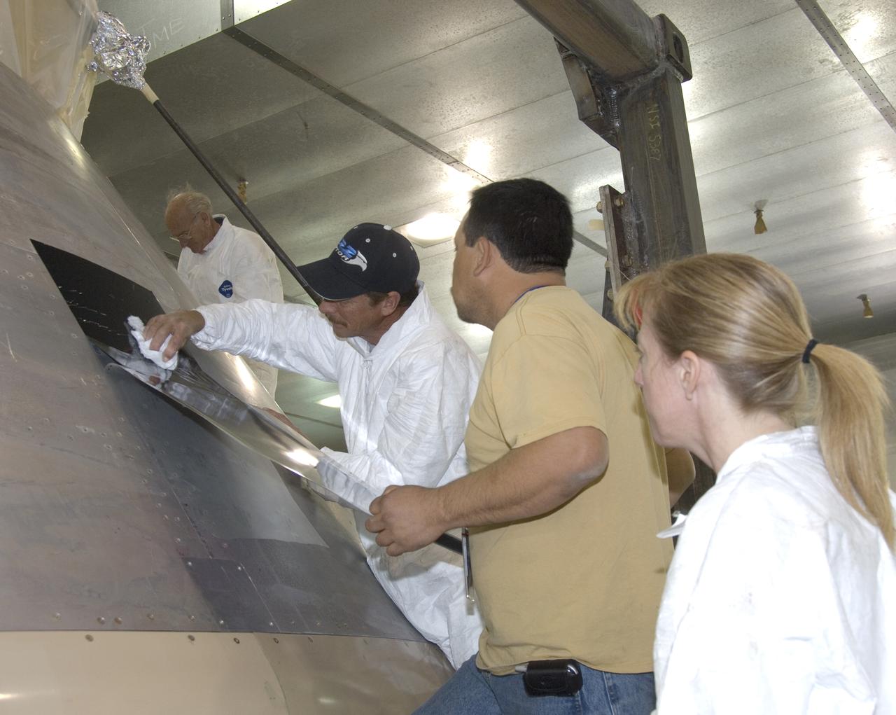
A full-scale flight-test mockup of the Constellation program's Orion crew vehicle arrived at NASA's Dryden Flight Research Center in late March 2008 to undergo preparations for the first short-range flight test of the spacecraft's astronaut escape system later that year. Engineers and technicians at NASA's Langley Research Center fabricated the structure, which precisely represents the size, outer shape and mass characteristics of the Orion space capsule. The Orion crew module mockup was ferried to NASA Dryden on an Air Force C-17. After painting in the Edwards Air Force Base paint hangar, the conical capsule was taken to Dryden for installation of flight computers, instrumentation and other electronics prior to being sent to the U.S. Army's White Sands Missile Range in New Mexico for integration with the escape system and the first abort flight test in late 2008. The tests were designed to ensure a safe, reliable method of escape for astronauts in case of an emergency.
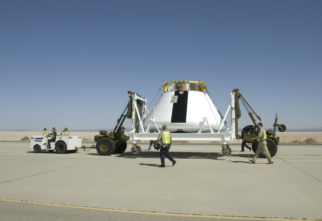
A full-scale flight-test mockup of the Constellation program's Orion crew vehicle arrived at NASA's Dryden Flight Research Center in late March 2008 to undergo preparations for the first short-range flight test of the spacecraft's astronaut escape system later that year. Engineers and technicians at NASA's Langley Research Center fabricated the structure, which precisely represents the size, outer shape and mass characteristics of the Orion space capsule. The Orion crew module mockup was ferried to NASA Dryden on an Air Force C-17. After painting in the Edwards Air Force Base paint hangar, the conical capsule was taken to Dryden for installation of flight computers, instrumentation and other electronics prior to being sent to the U.S. Army's White Sands Missile Range in New Mexico for integration with the escape system and the first abort flight test in late 2008. The tests were designed to ensure a safe, reliable method of escape for astronauts in case of an emergency.
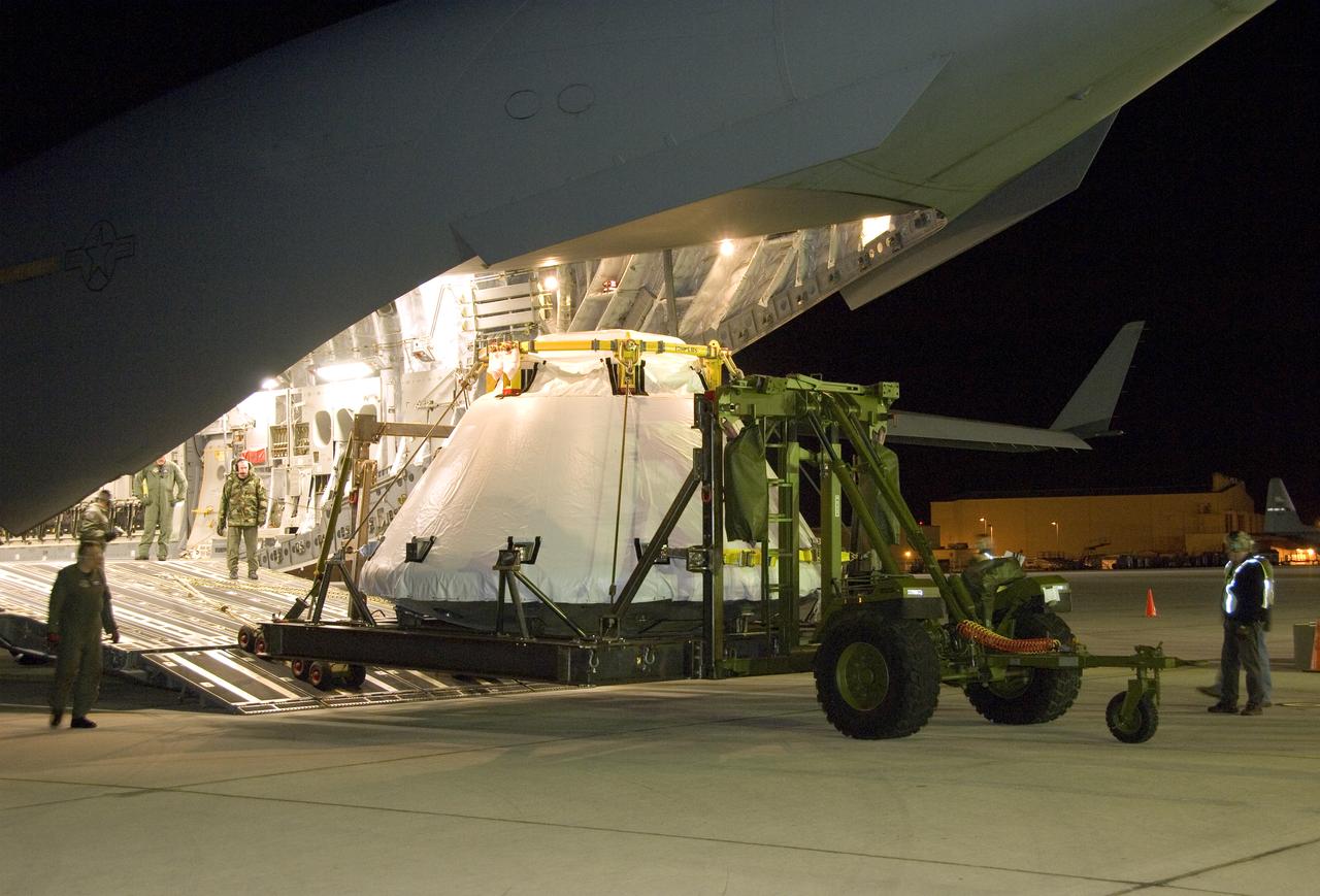
A full-scale flight-test mockup of the Constellation program's Orion crew vehicle arrived at NASA's Dryden Flight Research Center in late March 2008 to undergo preparations for the first short-range flight test of the spacecraft's astronaut escape system later that year. Engineers and technicians at NASA's Langley Research Center fabricated the structure, which precisely represents the size, outer shape and mass characteristics of the Orion space capsule. The Orion crew module mockup was ferried to NASA Dryden on an Air Force C-17. After painting in the Edwards Air Force Base paint hangar, the conical capsule was taken to Dryden for installation of flight computers, instrumentation and other electronics prior to being sent to the U.S. Army's White Sands Missile Range in New Mexico for integration with the escape system and the first abort flight test in late 2008. The tests were designed to ensure a safe, reliable method of escape for astronauts in case of an emergency.
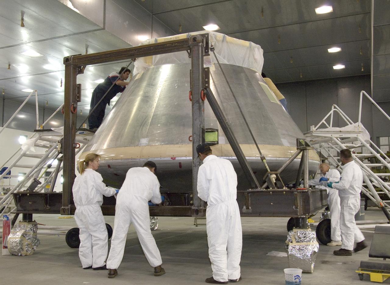
A full-scale flight-test mockup of the Constellation program's Orion crew vehicle arrived at NASA's Dryden Flight Research Center in late March 2008 to undergo preparations for the first short-range flight test of the spacecraft's astronaut escape system later that year. Engineers and technicians at NASA's Langley Research Center fabricated the structure, which precisely represents the size, outer shape and mass characteristics of the Orion space capsule. The Orion crew module mockup was ferried to NASA Dryden on an Air Force C-17. After painting in the Edwards Air Force Base paint hangar, the conical capsule was taken to Dryden for installation of flight computers, instrumentation and other electronics prior to being sent to the U.S. Army's White Sands Missile Range in New Mexico for integration with the escape system and the first abort flight test in late 2008. The tests were designed to ensure a safe, reliable method of escape for astronauts in case of an emergency.
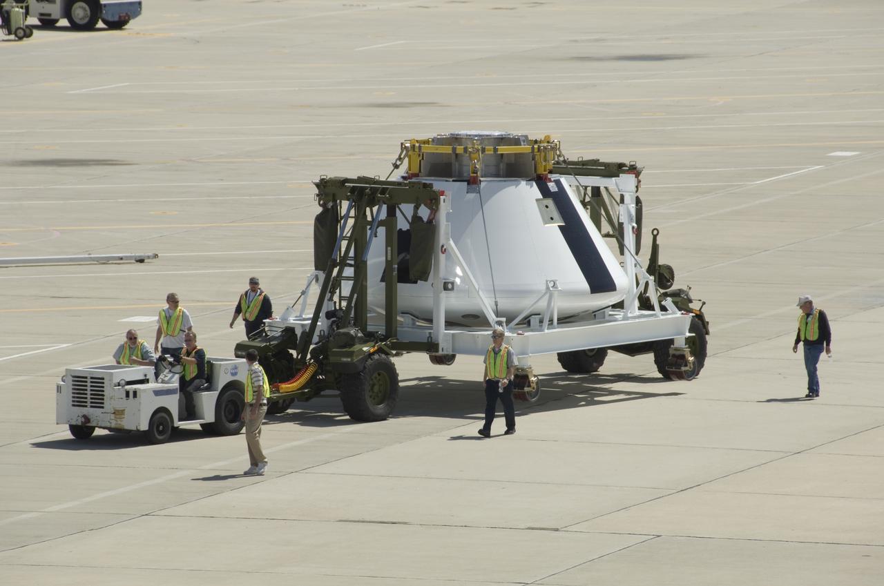
A full-scale flight-test mockup of the Constellation program's Orion crew vehicle arrived at NASA's Dryden Flight Research Center in late March 2008 to undergo preparations for the first short-range flight test of the spacecraft's astronaut escape system later that year. Engineers and technicians at NASA's Langley Research Center fabricated the structure, which precisely represents the size, outer shape and mass characteristics of the Orion space capsule. The Orion crew module mockup was ferried to NASA Dryden on an Air Force C-17. After painting in the Edwards Air Force Base paint hangar, the conical capsule was taken to Dryden for installation of flight computers, instrumentation and other electronics prior to being sent to the U.S. Army's White Sands Missile Range in New Mexico for integration with the escape system and the first abort flight test in late 2008. The tests were designed to ensure a safe, reliable method of escape for astronauts in case of an emergency.
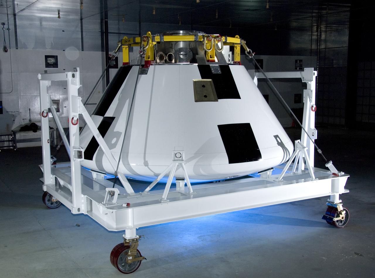
A full-scale flight-test mockup of the Constellation program's Orion crew vehicle arrived at NASA's Dryden Flight Research Center in late March 2008 to undergo preparations for the first short-range flight test of the spacecraft's astronaut escape system later that year. Engineers and technicians at NASA's Langley Research Center fabricated the structure, which precisely represents the size, outer shape and mass characteristics of the Orion space capsule. The Orion crew module mockup was ferried to NASA Dryden on an Air Force C-17. After painting in the Edwards Air Force Base paint hangar, the conical capsule was taken to Dryden for installation of flight computers, instrumentation and other electronics prior to being sent to the U.S. Army's White Sands Missile Range in New Mexico for integration with the escape system and the first abort flight test in late 2008. The tests were designed to ensure a safe, reliable method of escape for astronauts in case of an emergency.
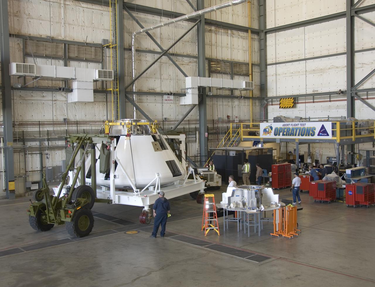
A full-scale flight-test mockup of the Constellation program's Orion crew vehicle arrived at NASA's Dryden Flight Research Center in late March 2008 to undergo preparations for the first short-range flight test of the spacecraft's astronaut escape system later that year. Engineers and technicians at NASA's Langley Research Center fabricated the structure, which precisely represents the size, outer shape and mass characteristics of the Orion space capsule. The Orion crew module mockup was ferried to NASA Dryden on an Air Force C-17. After painting in the Edwards Air Force Base paint hangar, the conical capsule was taken to Dryden for installation of flight computers, instrumentation and other electronics prior to being sent to the U.S. Army's White Sands Missile Range in New Mexico for integration with the escape system and the first abort flight test in late 2008. The tests were designed to ensure a safe, reliable method of escape for astronauts in case of an emergency.
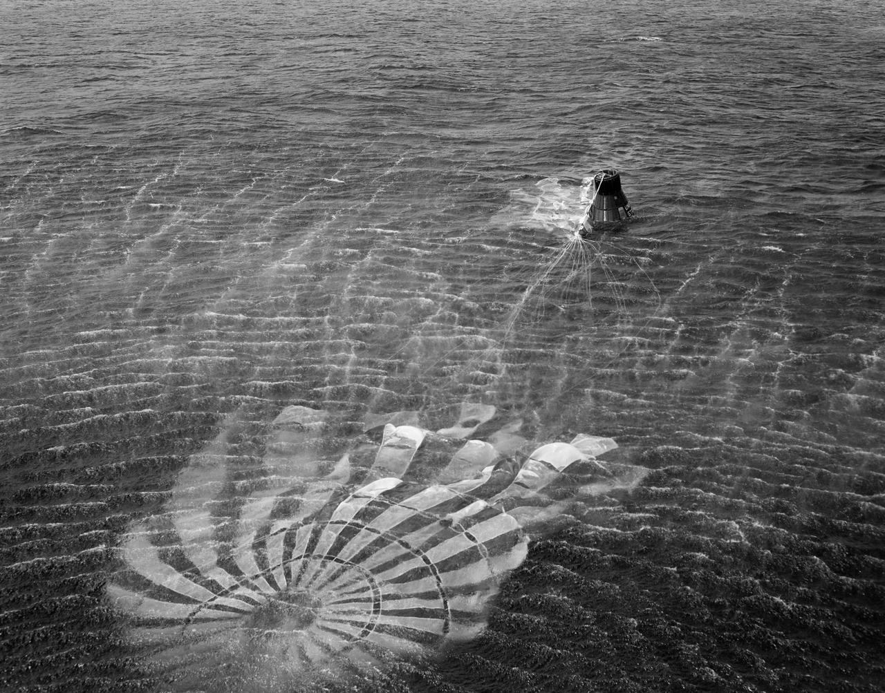
S61-01398 (18 March 1961) --- View of the recovery of the Little Joe-5A spacecraft which lifted off on March 18, 1961 from Wallops Island. The photo was taken from the recovery helicopter and shows the craft's parachute still attached and floating in the water next to the capsule. Little Joe-5A was a suborbital flight to test the Mercury capsule. The escape rocket motor fired prematurely and prior to capsule release. Photo credit: NASA

The launch of the Little Joe booster for the LJ1B mission on the launch pad from the wallops Flight Facility, Wallops Island, Virginia, on January 21, 1960. This mission achieved the suborbital Mercury capsule test, testing of the escape system, and biomedical tests by using a monkey, named Miss Sam.
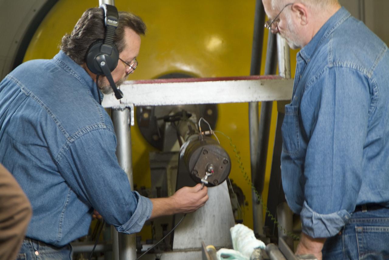
CEV (Crew Escape Vehicle) capsule Balistic Range testing to examine static and dynamic stability characteristics (at the Hypervelocity Free-Flight Facility) HFF - Don Bowling (l) attaching firing cable to breeth cap as Don Holt (r) looks on
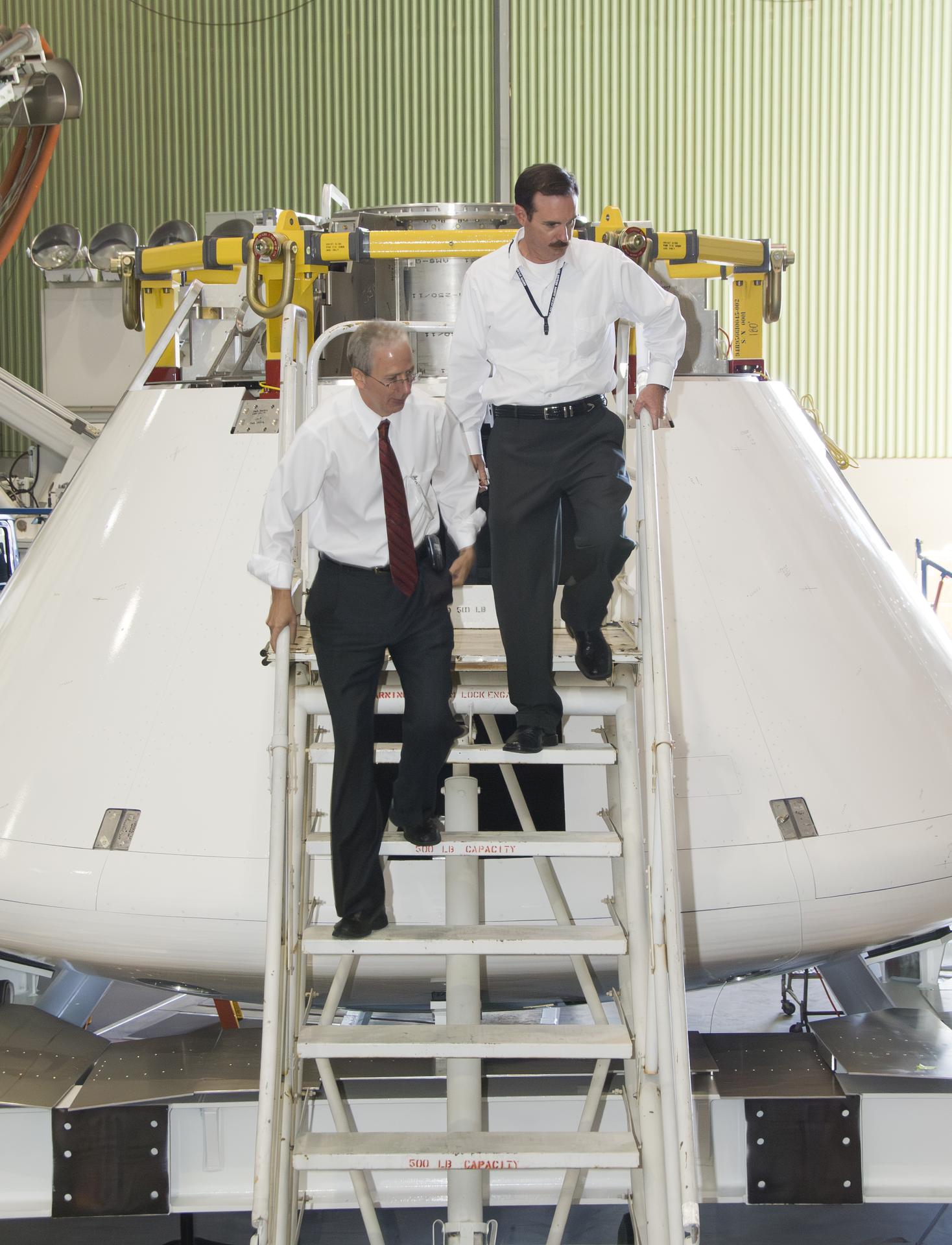
Mark Geyer, NASA’s Orion manager, visited NASA’s Armstrong Flight Research Center in Edwards, California, on April 9, 2008, to see the Pad Abort-1 test article, developed to demonstrate the Orion capsule’s emergency escape system during launch. Dave McAllister, NASA Armstrong Abort Flight Test operations lead, right, shows Geyer the Orion capsule mockup. Pad Abort-1 was later tested at the U.S. Army’s White Sands Missile Range in New Mexico, on May 6, 2010.
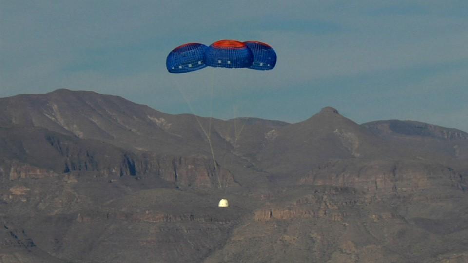
VAN HORN, Texas – Blue Origin’s New Shepard crew capsule escaped to an altitude of 2,307 feet before deploying parachutes for a safe return for a pad escape test at the company's West Texas launch site. The pusher escape system was designed and developed by Blue Origin to allow crew escape in the event of an emergency during any phase of ascent for its suborbital New Shepard system. As part of an incremental development program, the results of this test will shape the design of the escape system for the company's orbital biconic-shaped Space Vehicle. The system is expected to enable full reusability of the launch vehicle, which is different from NASA's previous launch escape systems that would pull a spacecraft away from its rocket before reaching orbit. The test was part of Blue Origin's work supporting its funded Space Act Agreement with NASA during Commercial Crew Development Round 2 CCDev2). Through initiatives like CCDev2, NASA is fostering the development of a U.S. commercial crew space transportation capability with the goal of achieving safe, reliable and cost-effective access to and from the International Space Station and low-Earth orbit. After the capability is matured and available to the government and other customers, NASA could contract to purchase commercial services to meet its station crew transportation needs. For more information, visit www.nasa.gov/commercialcrew. Image credit: Blue Origin
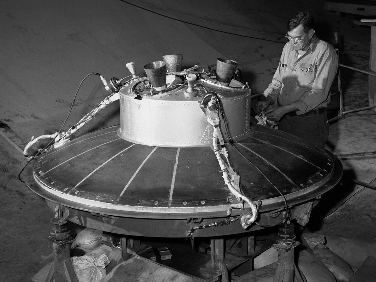
A mechanic at the National Aeronautics and Space Administration (NASA) Lewis Research Center prepares the inverted base of a Mercury capsule for a test of its posigrade retrorockets inside the Altitude Wind Tunnel. In October 1959 NASA’s Space Task Group allocated several Project Mercury assignments to Lewis. The Altitude Wind Tunnel was modified to test the Atlas separation system, study the escape tower rocket plume, train astronauts to bring a spinning capsule under control, and calibrate the capsule’s retrorockets. The turning vanes, makeup air pipes, and cooling coils were removed from the wide western end of the tunnel to create a 51-foot diameter test chamber. The Mercury capsule had a six-rocket retro-package affixed to the bottom of the capsule. Three of these were posigrade rockets used to separate the capsule from the booster and three were retrograde rockets used to slow the capsule for reentry into the earth’s atmosphere. Performance of the retrorockets was vital since there was no backup system. Qualification tests of the retrorockets began in April 1960 on a retrograde thrust stand inside the southwest corner of the Altitude Wind Tunnel. These studies showed that a previous issue concerning the delayed ignition of the propellant had been resolved. Follow-up test runs verified reliability of the igniter’s attachment to the propellant. In addition, the capsule’s retrorockets were calibrated so they would not alter the capsule’s attitude when fired.
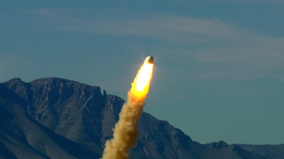
VAN HORN, Texas – Blue Origin’s pusher escape system rockets its New Shepard crew capsule away from a simulated propulsion module launch pad at the company's West Texas launch site, demonstrating a key safety system for both suborbital and orbital flights. The pad escape test took the company's suborbital crew capsule to an altitude of 2,307 feet during the flight test before descending safely by parachute to a soft landing 1,630 feet away. The pusher escape system was designed and developed by Blue Origin to allow crew escape in the event of an emergency during any phase of ascent for its suborbital New Shepard system. As part of an incremental development program, the results of this test will shape the design of the escape system for the company's orbital biconic-shaped Space Vehicle. The system is expected to enable full reusability of the launch vehicle, which is different from NASA's previous launch escape systems that would pull a spacecraft away from its rocket before reaching orbit. The test was part of Blue Origin's work supporting its funded Space Act Agreement with NASA during Commercial Crew Development Round 2 CCDev2). Through initiatives like CCDev2, NASA is fostering the development of a U.S. commercial crew space transportation capability with the goal of achieving safe, reliable and cost-effective access to and from the International Space Station and low-Earth orbit. After the capability is matured and available to the government and other customers, NASA could contract to purchase commercial services to meet its station crew transportation needs. For more information, visit www.nasa.gov/commercialcrew. Image credit: Blue Origin

Technicians prepare a full-scale capsule which would be used for the first rocket-launching on March 11, 1959. The purpose of the test would be to simulate a ground-level or beach abort. Joseph Shortal wrote (vol. 3, p. 27): It was a test of the ability of the escape system to rescue the astronaut in case of a malfunction of the launch vehicle prior to flight. This test was carried out by PARD under the direction of W.S. Blanchard, Jr., and was part of the program designated F57 at PARD. For these tests capsule shape C was used. -- Published in Joseph A. Shortal, History of Wallops Station: Origins and Activities Through 1949, (Wallops Island, VA: National Aeronautics and Space Administration, Wallops Station, nd), Comment Edition.
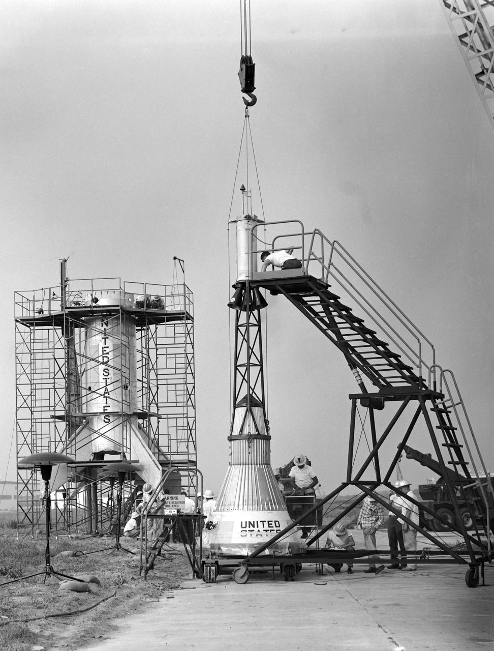
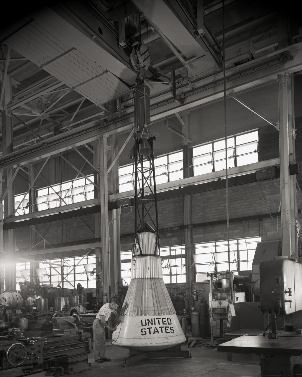
The Mercury capsule and escape tower are being lowered onto the Little Joe booster for launch on August 21, 1959. Joseph Shortal described this as follows (vol. 3, p. 33): The Little Joe booster was assembled at Wallops on its special launcher in a vertical attitude. It is shown in the on the left with the work platform in place. The launcher was located on a special concrete slab in Launching Area 1. The capsule was lowered onto the booster by crane.... After the assembly was completed, the scaffolding was disassembled and the launcher pitched over to its normal launch angle of 80 degrees.... Little Joe had a diameter of 80 inches and an overall length, including the capsule and escape tower of 48 feet. The total weight at launch was about 43,000 pounds. The overall span of the stabilizing fins was 21.3 feet. Although in comparison with the overall Mercury Project, Little Joe was a simple undertaking, the fact that an attempt was made to condense a normal two-year project into a 6-month one with in house labor turned it into a major undertaking for Langley. -- Published in Joseph A. Shortal, History of Wallops Station: Origins and Activities Through 1949, (Wallops Island, VA: National Aeronautics and Space Administration, Wallops Station, nd), Comment Edition.
The Mercury capsule and escape tower are being lowered onto the Little Joe booster for launch on August 21, 1959. Joseph Shortal described this as follows (vol. 3, p. 33): The Little Joe booster was assembled at Wallops on its special launcher in a vertical attitude. It is shown in the on the left with the work platform in place. The launcher was located on a special concrete slab in Launching Area 1. The capsule was lowered onto the booster by crane.... After the assembly was completed, the scaffolding was disassembled and the launcher pitched over to its normal launch angle of 80 degrees.... Little Joe had a diameter of 80 inches and an overall length, including the capsule and escape tower of 48 feet. The total weight at launch was about 43,000 pounds. The overall span of the stabilizing fins was 21.3 feet. Although in comparison with the overall Mercury Project, Little Joe was a simple undertaking, the fact that an attempt was made to condense a normal two-year project into a 6-month one with in house labor turned it into a major undertaking for Langley. -- Published in Joseph A. Shortal, History of Wallops Station: Origins and Activities Through 1949, (Wallops Island, VA: National Aeronautics and Space Administration, Wallops Station, nd), Comment Edition.
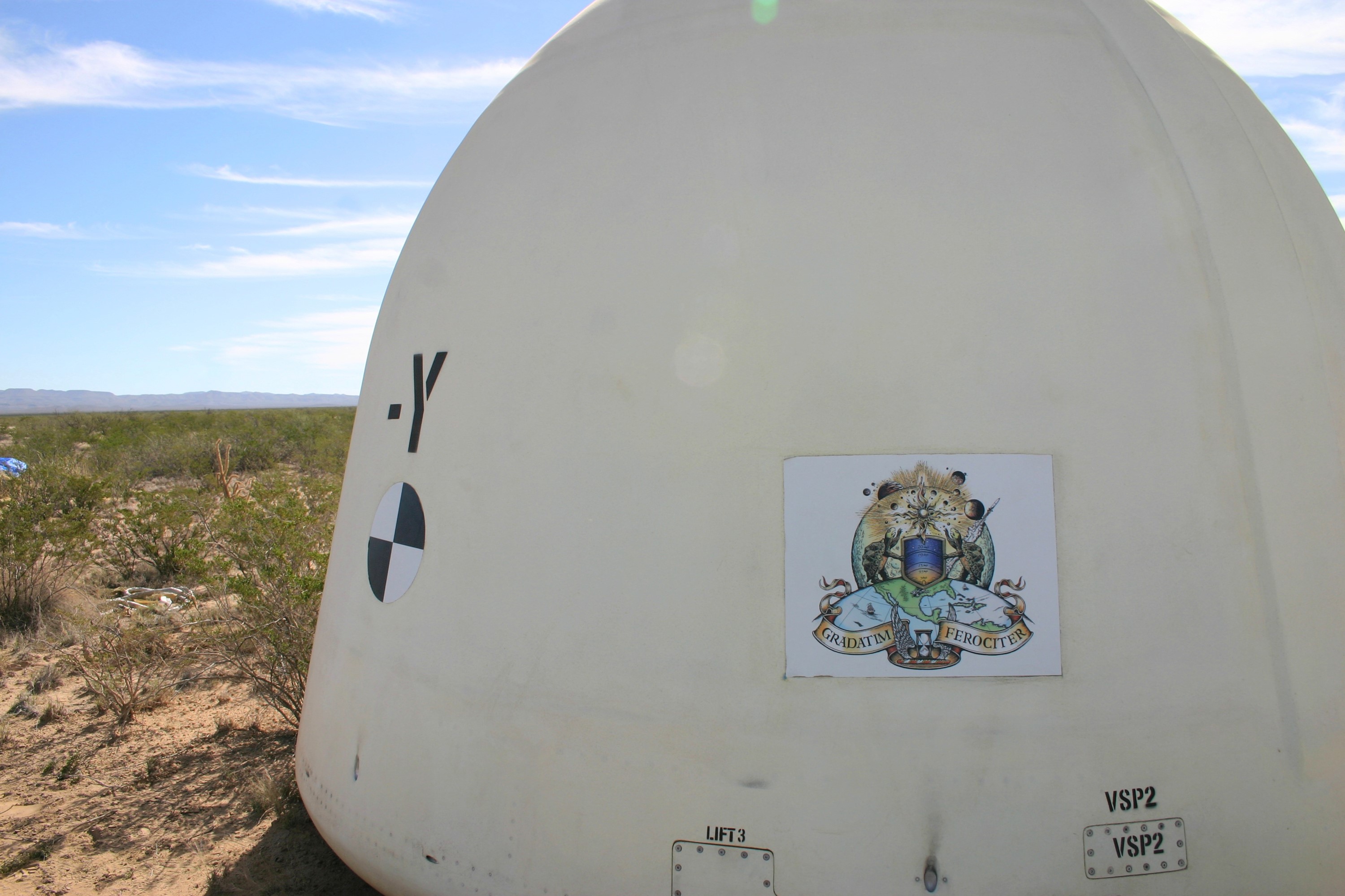
VAN HORN, Texas – Blue Origin’s New Shepard crew capsule touched down 1,630 feet from the its simulated propulsion module launch pad at the company's West Texas launch site, completing a successful test of its New Shepard crew capsule escape system. The pusher escape system was designed and developed by Blue Origin to allow crew escape in the event of an emergency during any phase of ascent for its suborbital New Shepard system. As part of an incremental development program, the results of this test will shape the design of the escape system for the company's orbital biconic-shaped Space Vehicle. The system is expected to enable full reusability of the launch vehicle, which is different from NASA's previous launch escape systems that would pull a spacecraft away from its rocket before reaching orbit. The test was part of Blue Origin's work supporting its funded Space Act Agreement with NASA during Commercial Crew Development Round 2 CCDev2). Through initiatives like CCDev2, NASA is fostering the development of a U.S. commercial crew space transportation capability with the goal of achieving safe, reliable and cost-effective access to and from the International Space Station and low-Earth orbit. After the capability is matured and available to the government and other customers, NASA could contract to purchase commercial services to meet its station crew transportation needs. For more information, visit www.nasa.gov/commercialcrew. Image credit: Blue Origin
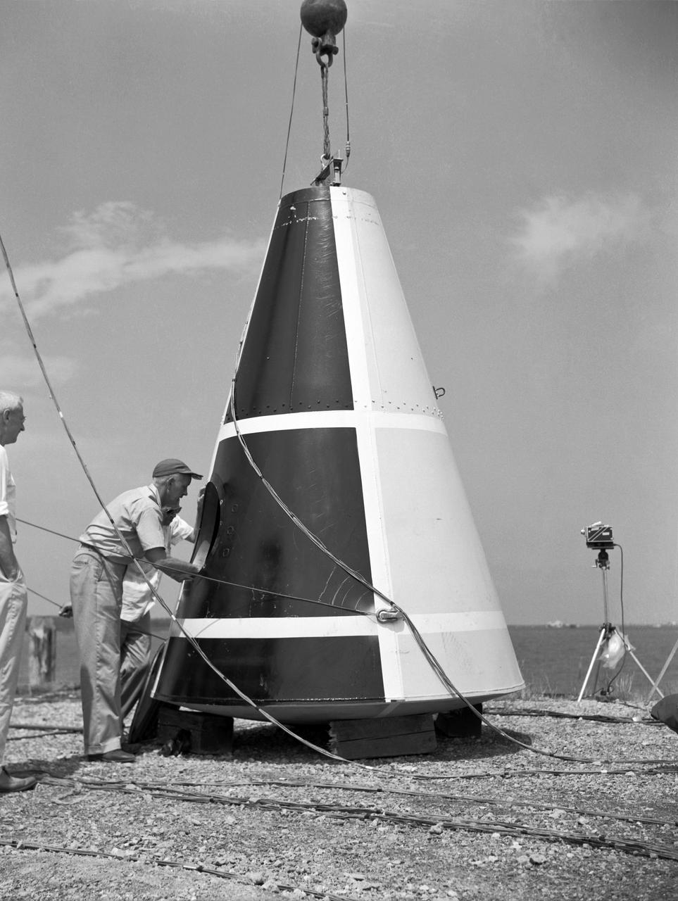
Photographed on: 08 05 1958. -- Impact test conducted by Langley's Hydrodynamics Division. The Division conducted a series of impact studies with full scale and model capsules of the original capsule shape A. Joseph Shortal wrote (Vol. 3, p. 16): The basic design of the capsule was made by M.A. Faget and his coworkers at PARD during the winter of 1957-1958. It was natural, then, that extensive use was made of the facilities at Wallops during the development of the spacecraft. The tests at Wallops consisted of 26 full-size capsules, either launched from the ground by rocket power or dropped from airplanes at high altitude and 28 scaled models, either rocket boosted or released from balloons. Emphasis in the Wallops program was on dynamic stability and aerodynamic heating of the capsule, and effectiveness of the pilot-escape and parachute-recovery systems. The biggest part of the Wallops program was the series of full-size capsules, rocket launched with the Little Joe booster, developed especially for Mercury. -- Published in Joseph A. Shortal, History of Wallops Station: Origins and Activities Through 1949, (Wallops Island, VA: National Aeronautics and Space Administration, Wallops Station, nd), Comment Edition.
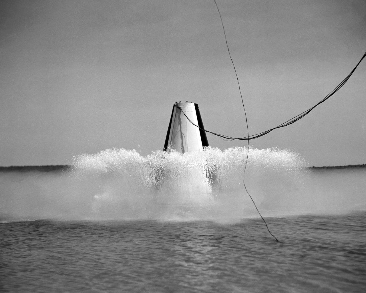
Photographed on: 08 05 1958. -- Impact test conducted by Langley's Hydrodynamics Division. The Division conducted a series of impact studies with full scale and model capsules of the original capsule shape A. Joseph Shortal wrote (Vol. 3, p. 16): The basic design of the capsule was made by M.A. Faget and his coworkers at PARD during the winter of 1957-1958. It was natural, then, that extensive use was made of the facilities at Wallops during the development of the spacecraft. The tests at Wallops consisted of 26 full-size capsules, either launched from the ground by rocket power or dropped from airplanes at high altitude and 28 scaled models, either rocket boosted or released from balloons. Emphasis in the Wallops program was on dynamic stability and aerodynamic heating of the capsule, and effectiveness of the pilot-escape and parachute-recovery systems. The biggest part of the Wallops program was the series of full-size capsules, rocket launched with the Little Joe booster, developed especially for Mercury. -- Published in Joseph A. Shortal, History of Wallops Station: Origins and Activities Through 1949, (Wallops Island, VA: National Aeronautics and Space Administration, Wallops Station, nd), Comment Edition.
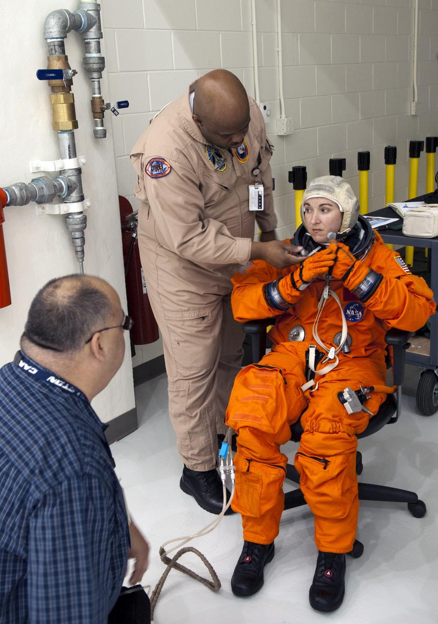
CAPE CANAVERAL, Fla. – In the Operations and Checkout Building at NASA's Kennedy Space Center in Florida, United Space Alliance space suit specialists prepare to demonstrate the placement of crew seats and equipment inside an Orion crew exploration vehicle mock-up. Crew escape equipment suit technician Andre Denard, the STS-132 crew chief, assists United Space Alliance EV_IV Integrated Operations work control specialist Jennifer Peterson, as she dresses in a flight-and-entry suit. Looking on is crew escape equipment suit engineer Thomas Carlton. The mock-up details the interior components of the vehicle including seat layout and the subsystem components on the outside of the pressure vessel. Orion mock-ups also have been used to verify accessibility of the servicing locations at the launch pad and in the Vehicle Assembly Building. For information on the development of the Orion capsule, visit www.nasa.gov_orion. Photo credit: NASA_Jim Grossmann

Space Station Freedom option A showing two Soyuz Assured Crew Return Vehicle (ACRV) capsules docked at berthing ports.
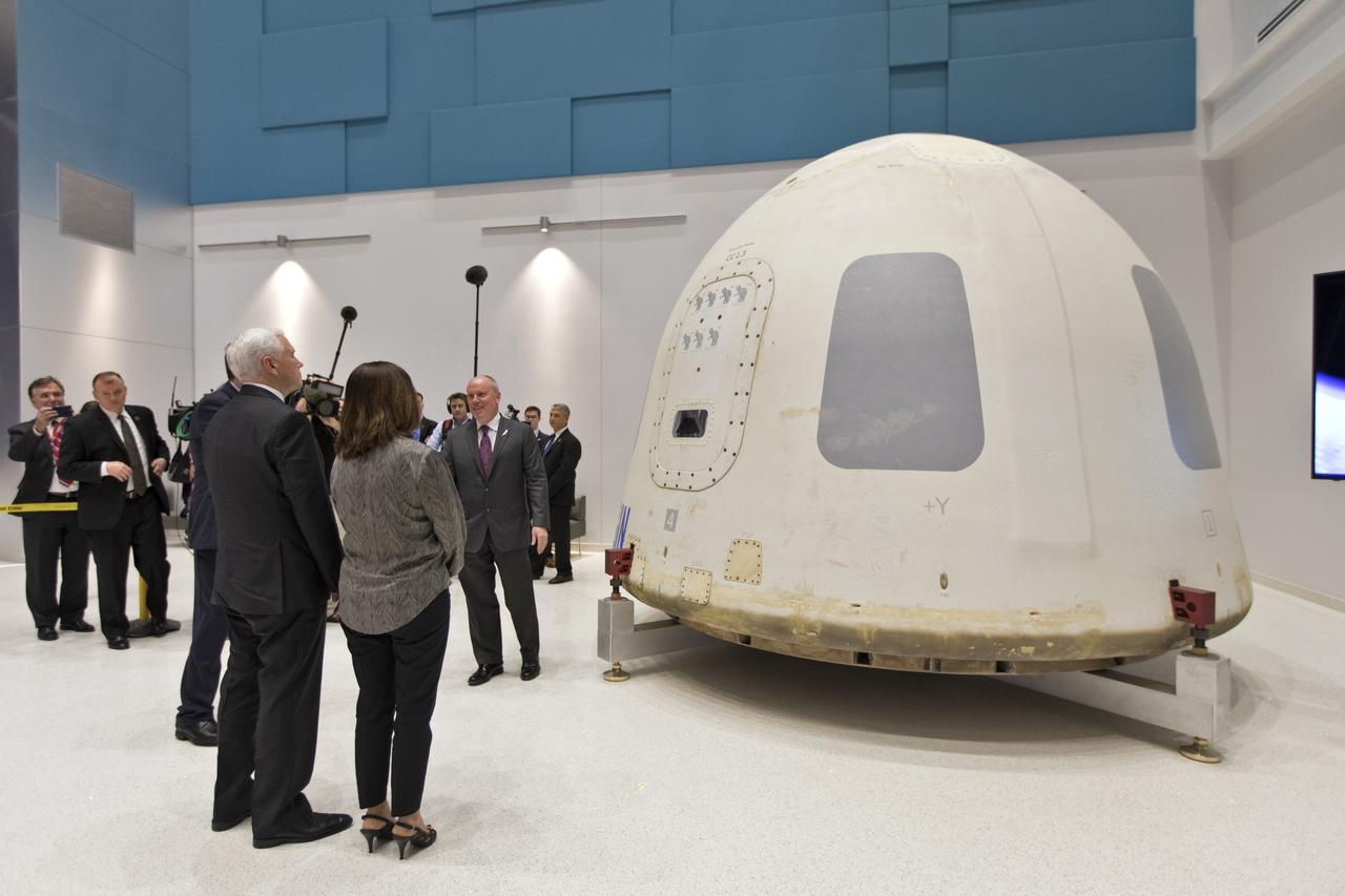
Vice President Mike Pence, second from right, and his wife, Karen Pence, tour the Blue Origin Manufacturing Facility near NASA's Kennedy Space Center in Florida, on Feb. 20, 2018. Vice President Pence viewed the flown New Shepard Booster and Crew Capsule. The Crew Capsule, in view, flew seven times, including a pad abort test and an escape test at maximum dynamic pressure. During his visit, Pence will chair a meeting of the National Space Council on Feb. 21, 2018 in the high bay of NASA Kennedy Space Center's Space Station Processing Facility. The council's role is to advise the president regarding national space policy and strategy, and review the nation's long-range goals for space activities.
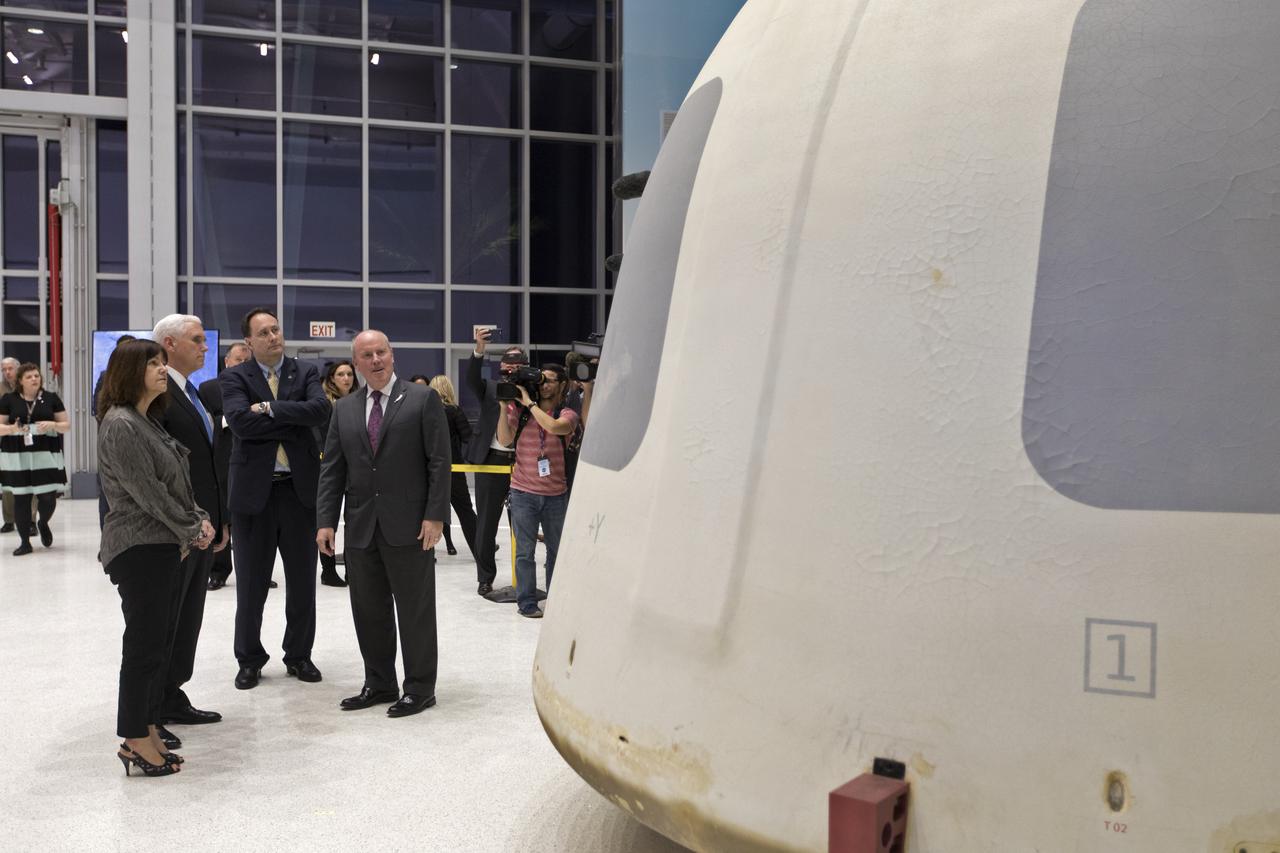
Vice President Mike Pence, second from left, tours the Blue Origin Manufacturing Facility near NASA's Kennedy Space Center in Florida, on Feb. 20, 2018. At far left is the vice president's wife, Karen Pence. To the right of Vice President Pence are acting NASA Administrator Robert Lightfoot and Blue Origin CEO Robert Smith. Pence viewed the flown New Shepard Booster and Crew Capsule. The Crew Capsule, in view, flew seven times, including a pad abort test and an escape test at maximum dynamic pressure. During his visit, Pence will chair a meeting of the National Space Council on Feb. 21, 2018 in the high bay of NASA Kennedy Space Center's Space Station Processing Facility. The council's role is to advise the president regarding national space policy and strategy, and review the nation's long-range goals for space activities.
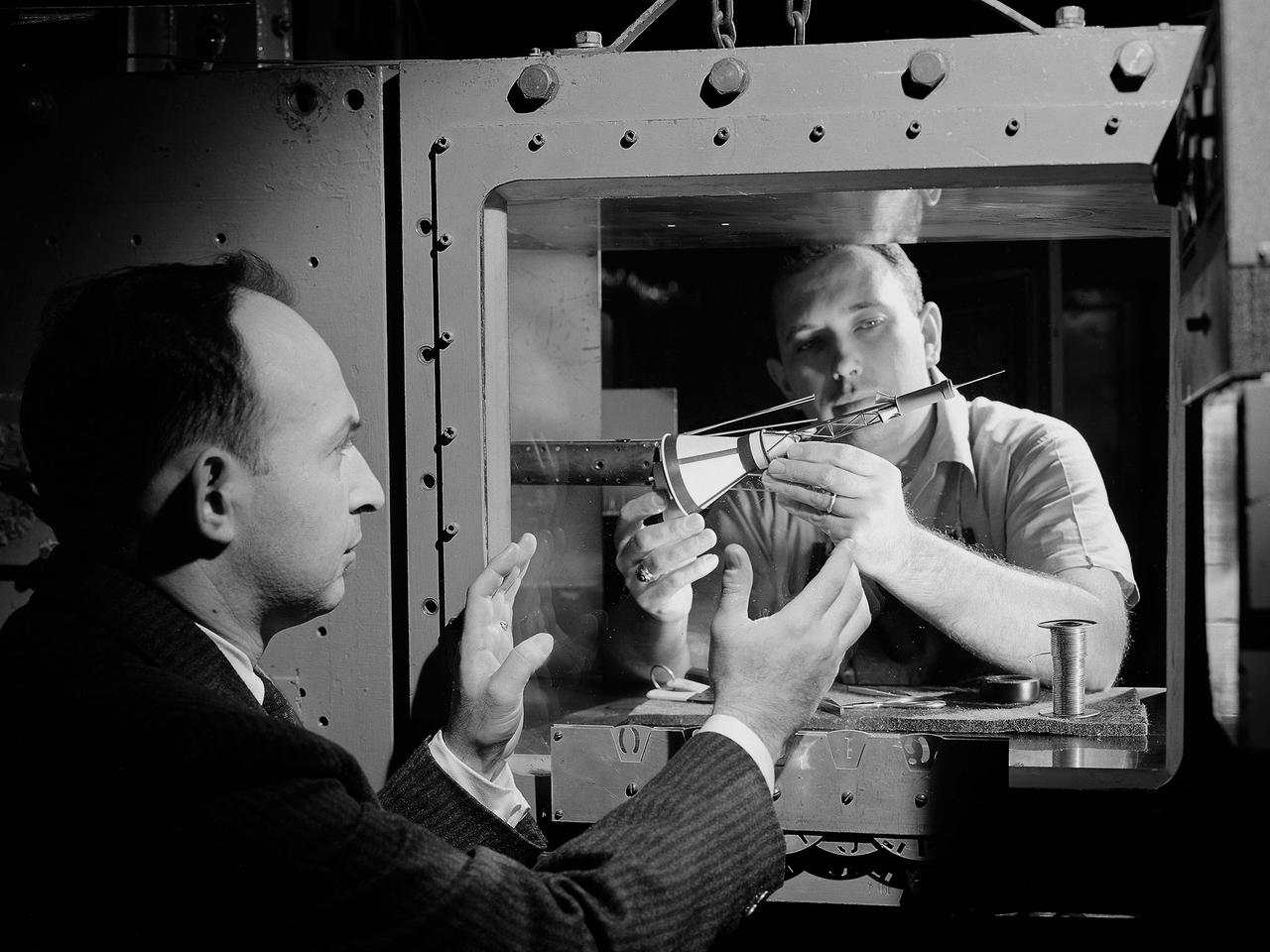
National Aeronautics and Space Administration (NASA) researchers install a small-scale model of the capsule for Project Mercury in the 1- by 1-Foot Supersonic Wind Tunnel at the Lewis Research Center. NASA Lewis conducted a variety of tests for Project Mercury, including retrorocket calibration, escape tower engine performance, and separation of the capsule from simulated Atlas and Redstone boosters. The test of this capsule and escape tower model in the 1- by 1-foot tunnel were run in January and February 1960. The 1-by 1-Foot Supersonic Wind Tunnel had a 15-inch long test section, seen here, that was one foot wide and one foot high. The sides were made of glass to allow cameras to capture the supersonic air flow over the models. The tunnel could generate air flows from Mach 1.3 to 3.0. At the time, it was one of nine small supersonic wind tunnels at Lewis. These tunnels used the exhauster and compressor equipment of the larger facilities. The 1- by 1 tunnel, which began operating in the early 1950s, was built inside a test cell in the expansive Engine Research Building. During the 1950s the 1- by 1 was used to study a variety of inlets, nozzles, and cones for missiles and scramjets. The Mercury capsule tests were among the last at the facility for many years. The tunnel was mothballed in 1960. The 1- by 1 was briefly restored in 1972, then brought back online for good in 1979. The facility has maintained a brisk operating schedule ever since.
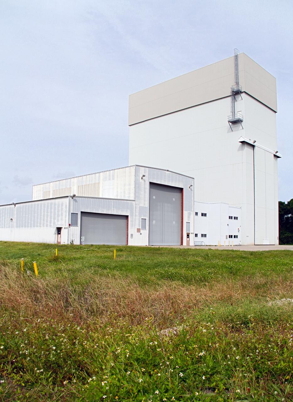
CAPE CANAVERAL, Fla. –The Launch Abort System Facility, or LASF, formerly known as the Canister Rotation Facility, is being outfitted and prepared for use by NASA's Orion Program to process the Launch Abort System, a multi-story rocket that will be positioned atop an Orion capsule to provide an escape system for astronauts during countdown and launch into orbit. The structure, the industrial area of NASA's Kennedy Space Center in Florida, served the Space Shuttle Program by standing the payload canister up so it could be taken to the launch pad and its contents transferred into the shuttle's cargo bay. Photo credit: NASA/Cory Huston
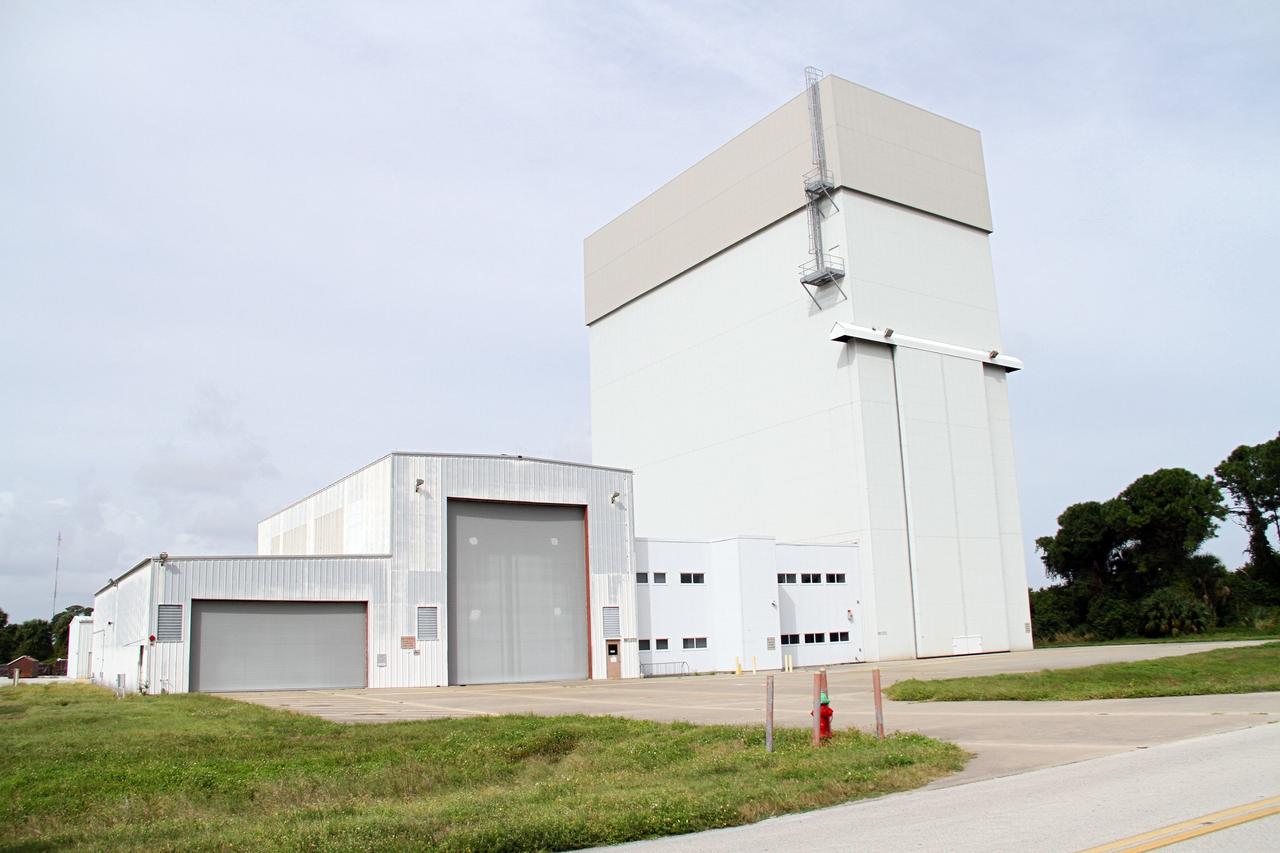
CAPE CANAVERAL, Fla. –The Launch Abort System Facility, or LASF, formerly known as the Canister Rotation Facility, is being outfitted and prepared for use by NASA's Orion Program to process the Launch Abort System, a multi-story rocket that will be positioned atop an Orion capsule to provide an escape system for astronauts during countdown and launch into orbit. The structure, the industrial area of NASA's Kennedy Space Center in Florida, served the Space Shuttle Program by standing the payload canister up so it could be taken to the launch pad and its contents transferred into the shuttle's cargo bay. Photo credit: NASA/Cory Huston
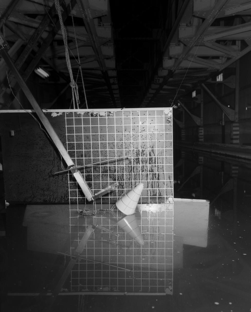
Testing of Mercury Capsule Shape A by the Hydrodynamics Division of Langley. Joseph Shortal wrote (vol. 3, p. 19): The Hydrodynamics Division provided assistance in determining landing loads. In this connection, after PARD engineers had unofficially approached that division to make some water impact tests with the boilerplate capsule, J.B. Parkinson, Hydrodynamics Chief visited Shortal to find out if the request had his support. Finding out that it did, Parkinson said, Its your capsule. If you want us to drop it in the water, we will do it. From Shortal (Vol. 3, p. 16): The basic design of the capsule was made by M.A. Faget and his coworkers at PARD during the winter of 1957-1958. It was natural, then, that extensive use was made of the facilities at Wallops during the development of the spacecraft. The tests at Wallops consisted of 26 full-size capsules, either launched from the ground by rocket power or dropped from airplanes at high altitude and 28 scaled models, either rocket boosted or released from balloons. Emphasis in the Wallops program was on dynamic stability and aerodynamic heating of the capsule, and effectiveness of the pilot-escape and parachute-recovery systems. The biggest part of the Wallops program was the series of full-size capsules, rocket launched with the Little Joe booster, developed especially for Mercury. -- Published in Joseph A. Shortal, History of Wallops Station: Origins and Activities Through 1949, (Wallops Island, VA: National Aeronautics and Space Administration, Wallops Station, nd), Comment Edition.

Assembling the Little Joe capsules. The capsules were manufactured in-house by Langley technicians. Three capsules are shown here in various stages of assembly. The escape tower and rocket motors shown on the completed capsule would be removed before shipping and finally assembly for launching at Wallops Island. Joseph Shortal wrote (vol. 3, p. 32): Design of the Little Joe capsules began at Langley before McDonnell started on the design of the Mercury capsule and was, therefore, a separate design. Although it was not designed to carry a man, it did have to carry a monkey. It had to meet the weight and center of gravity requirements of Mercury and withstand the same aerodynamic loads during the exit trajectory. Although in comparison with the overall Mercury Project, Little Joe was a simple undertaking, the fact that an attempt was made to condense a normal two-year project into a 6-month one with in house labor turned it into a major undertaking for Langley. Project Mercury: Little Joe: Boilerplate Mercury spacecraft undergo fabrication at the shops of the Langley Research Center. They will launched atop Little Joe rockets to test the spacecraft recovery systems. -- Published in Joseph A. Shortal, History of Wallops Station: Origins and Activities Through 1949, (Wallops Island, VA: National Aeronautics and Space Administration, Wallops Station, nd), Comment Edition. L59-4947 Technicians prepare a Little Joe launch vehicle prototype for the Mercury space program, 1959. Photograph published in Winds of Change, 75th Anniversary NASA publication, page 76, by James Schultz

Assembling the Little Joe capsules. The capsules were manufactured in-house by Langley technicians. Three capsules are shown here in various stages of assembly. The escape tower and rocket motors shown on the completed capsule would be removed before shipping and finally assembly for launching at Wallops Island. Joseph Shortal wrote (vol. 3, p. 32): Design of the Little Joe capsules began at Langley before McDonnell started on the design of the Mercury capsule and was, therefore, a separate design. Although it was not designed to carry a man, it did have to carry a monkey. It had to meet the weight and center of gravity requirements of Mercury and withstand the same aerodynamic loads during the exit trajectory. Although in comparison with the overall Mercury Project, Little Joe was a simple undertaking, the fact that an attempt was made to condense a normal two-year project into a 6-month one with in house labor turned it into a major undertaking for Langley. Project Mercury: Little Joe: Boilerplate Mercury spacecraft undergo fabrication at the shops of the Langley Research Center. They will launched atop Little Joe rockets to test the spacecraft recovery systems. -- Published in Joseph A. Shortal, History of Wallops Station: Origins and Activities Through 1949, (Wallops Island, VA: National Aeronautics and Space Administration, Wallops Station, nd), Comment Edition. L59-4947 Technicians prepare a Little Joe launch vehicle prototype for the Mercury space program, 1959. Photograph published in Winds of Change, 75th Anniversary NASA publication, page 76, by James Schultz
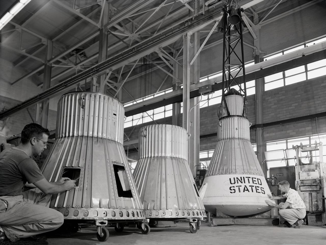
Assembling the Little Joe capsules. The capsules were manufactured in-house by Langley technicians. Three capsules are shown here in various stages of assembly. The escape tower and rocket motors shown on the completed capsule would be removed before shipping and finally assembly for launching at Wallops Island. Joseph Shortal wrote (vol. 3, p. 32): Design of the Little Joe capsules began at Langley before McDonnell started on the design of the Mercury capsule and was, therefore, a separate design. Although it was not designed to carry a man, it did have to carry a monkey. It had to meet the weight and center of gravity requirements of Mercury and withstand the same aerodynamic loads during the exit trajectory. Although in comparison with the overall Mercury Project, Little Joe was a simple undertaking, the fact that an attempt was made to condense a normal two-year project into a 6-month one with in house labor turned it into a major undertaking for Langley. Project Mercury: Little Joe: Boilerplate Mercury spacecraft undergo fabrication at the shops of the Langley Research Center. They will launched atop Little Joe rockets to test the spacecraft recovery systems. -- Published in Joseph A. Shortal, History of Wallops Station: Origins and Activities Through 1949, (Wallops Island, VA: National Aeronautics and Space Administration, Wallops Station, nd), Comment Edition. L59-4947 Technicians prepare a Little Joe launch vehicle prototype for the Mercury space program, 1959. Photograph published in Winds of Change, 75th Anniversary NASA publication, page 76, by James Schultz
Assembling the Little Joe capsules. The capsules were manufactured in-house by Langley technicians. Three capsules are shown here in various stages of assembly. The escape tower and rocket motors shown on the completed capsule would be removed before shipping and finally assembly for launching at Wallops Island. Joseph Shortal wrote (vol. 3, p. 32): Design of the Little Joe capsules began at Langley before McDonnell started on the design of the Mercury capsule and was, therefore, a separate design. Although it was not designed to carry a man, it did have to carry a monkey. It had to meet the weight and center of gravity requirements of Mercury and withstand the same aerodynamic loads during the exit trajectory. Although in comparison with the overall Mercury Project, Little Joe was a simple undertaking, the fact that an attempt was made to condense a normal two-year project into a 6-month one with in house labor turned it into a major undertaking for Langley. Project Mercury: Little Joe: Boilerplate Mercury spacecraft undergo fabrication at the shops of the Langley Research Center. They will launched atop Little Joe rockets to test the spacecraft recovery systems. -- Published in Joseph A. Shortal, History of Wallops Station: Origins and Activities Through 1949, (Wallops Island, VA: National Aeronautics and Space Administration, Wallops Station, nd), Comment Edition. L59-4947 Technicians prepare a Little Joe launch vehicle prototype for the Mercury space program, 1959. Photograph published in Winds of Change, 75th Anniversary NASA publication, page 76, by James Schultz
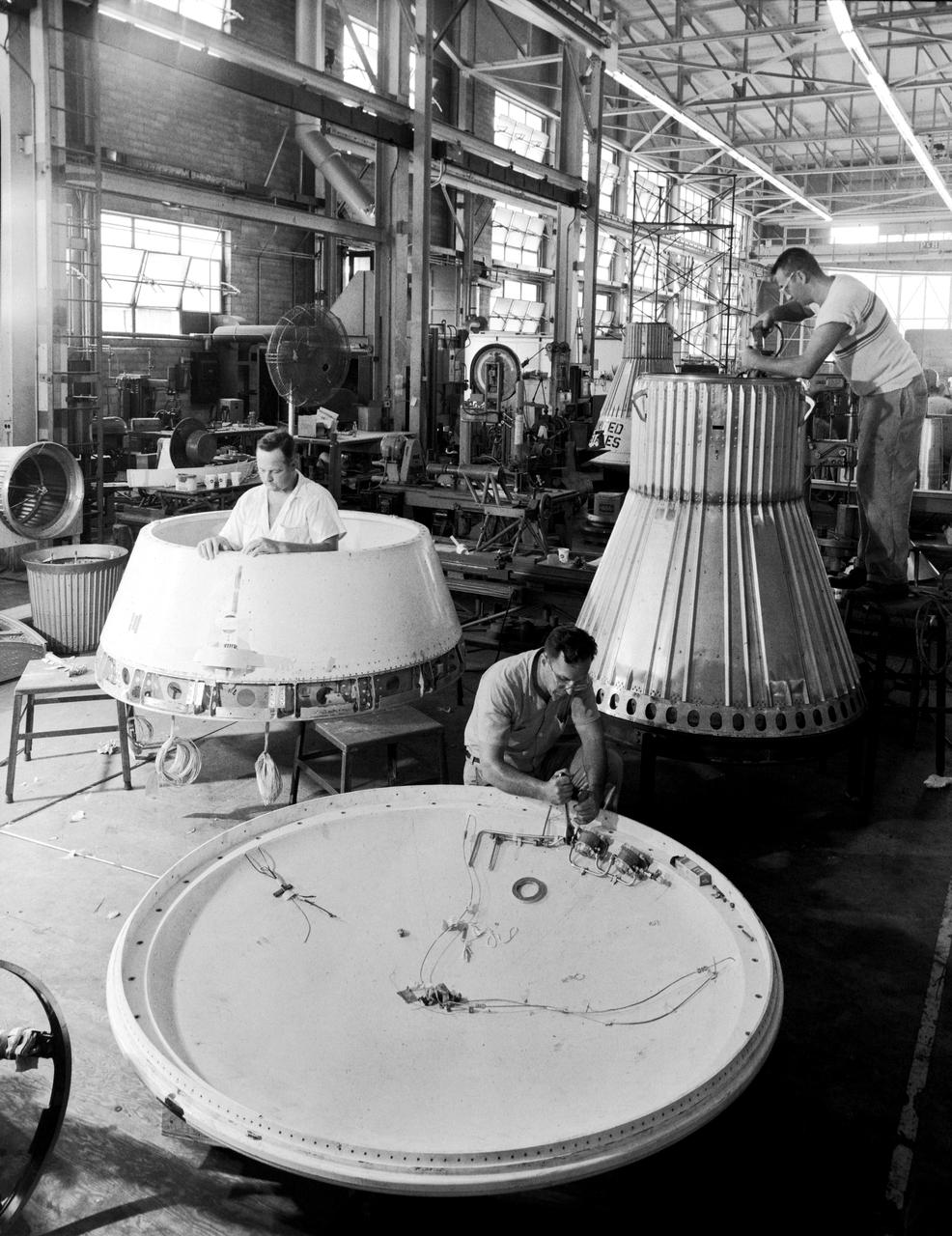
Assembling the Little Joe capsules. The capsules were manufactured in-house by Langley technicians. Three capsules are shown here in various stages of assembly. The escape tower and rocket motors shown on the completed capsule would be removed before shipping and finally assembly for launching at Wallops Island. Joseph Shortal wrote (vol. 3, p. 32): Design of the Little Joe capsules began at Langley before McDonnell started on the design of the Mercury capsule and was, therefore, a separate design. Although it was not designed to carry a man, it did have to carry a monkey. It had to meet the weight and center of gravity requirements of Mercury and withstand the same aerodynamic loads during the exit trajectory. Although in comparison with the overall Mercury Project, Little Joe was a simple undertaking, the fact that an attempt was made to condense a normal two-year project into a 6-month one with in house labor turned it into a major undertaking for Langley. Project Mercury: Little Joe: Boilerplate Mercury spacecraft undergo fabrication at the shops of the Langley Research Center. They will launched atop Little Joe rockets to test the spacecraft recovery systems. -- Published in Joseph A. Shortal, History of Wallops Station: Origins and Activities Through 1949, (Wallops Island, VA: National Aeronautics and Space Administration, Wallops Station, nd), Comment Edition. L59-4947 Technicians prepare a Little Joe launch vehicle prototype for the Mercury space program, 1959. Photograph published in Winds of Change, 75th Anniversary NASA publication, page 76, by James Schultz

Assembling the Little Joe capsules. The capsules were manufactured in-house by Langley technicians. Three capsules are shown here in various stages of assembly. The escape tower and rocket motors shown on the completed capsule would be removed before shipping and finally assembly for launching at Wallops Island. Joseph Shortal wrote (vol. 3, p. 32): Design of the Little Joe capsules began at Langley before McDonnell started on the design of the Mercury capsule and was, therefore, a separate design. Although it was not designed to carry a man, it did have to carry a monkey. It had to meet the weight and center of gravity requirements of Mercury and withstand the same aerodynamic loads during the exit trajectory. Although in comparison with the overall Mercury Project, Little Joe was a simple undertaking, the fact that an attempt was made to condense a normal two-year project into a 6-month one with in house labor turned it into a major undertaking for Langley. Project Mercury: Little Joe: Boilerplate Mercury spacecraft undergo fabrication at the shops of the Langley Research Center. They will launched atop Little Joe rockets to test the spacecraft recovery systems. -- Published in Joseph A. Shortal, History of Wallops Station: Origins and Activities Through 1949, (Wallops Island, VA: National Aeronautics and Space Administration, Wallops Station, nd), Comment Edition. L59-4947 Technicians prepare a Little Joe launch vehicle prototype for the Mercury space program, 1959. Photograph published in Winds of Change, 75th Anniversary NASA publication, page 76, by James Schultz
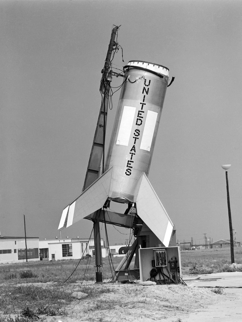
Testing of the Little Joe booster on its launcher. The launcher is positioned at its normal launch angle of 80 degrees. Joseph Shortal wrote (vol. 3, p. 33): The Little Joe booster was assembled at Wallops on its special launcher in a vertical attitude. It is shown in the on the left with the work platform in place. The launcher was located on a special concrete slab in Launching Area 1. The capsule was lowered onto the booster by crane.... After the assembly was completed, the scaffolding was disassembled and the launcher pitched over to its normal launch angle of 80 degrees.... Little Joe had a diameter of 80 inches and an overall length, including the capsule and escape tower of 48 feet. The total weight at launch was about 43,000 pounds. The overall span of the stabilizing fins was 21.3 feet. Although in comparison with the overall Mercury Project, Little Joe was a simple undertaking, the fact that an attempt was made to condense a normal two-year project into a 6-month one with in house labor turned it into a major undertaking for Langley. -- Published in Joseph A. Shortal, History of Wallops Station: Origins and Activities Through 1949, (Wallops Island, VA: National Aeronautics and Space Administration, Wallops Station, nd), Comment Edition.

The Earth Return Orbiter (ERO) is one of the flight missions making up the Mars Sample Return campaign to bring martian rock and atmospheric samples back to Earth. The ESA orbiter would be the first interplanetary spacecraft to capture samples in orbit and make a return trip between Earth and Mars. The primary mission of the European spacecraft would be to find, fly to, and capture a volleyball-sized capsule called the Orbiting Sample (OS) container launched from the surface of Mars by NASA's Mars Ascent System and carrying a carefully selected set of samples previously collected on the surface of Mars by NASA's Perseverance rover. Having already spent three years to reach Mars and perform its rendezvous and capture mission, ERO would take a further two years to fly from its operational orbit around Mars up to escape altitude and make its way back to Earth. When ERO is about three days from Earth, the Earth Entry System (EES) carrying the OS would separate from the spacecraft and be placed on a precision trajectory for Earth entry and landing. The Earth Return Orbiter is part of the multi-mission Mars Sample Return campaign being planned by NASA and the European Space Agency (ESA). https://photojournal.jpl.nasa.gov/catalog/PIA25893
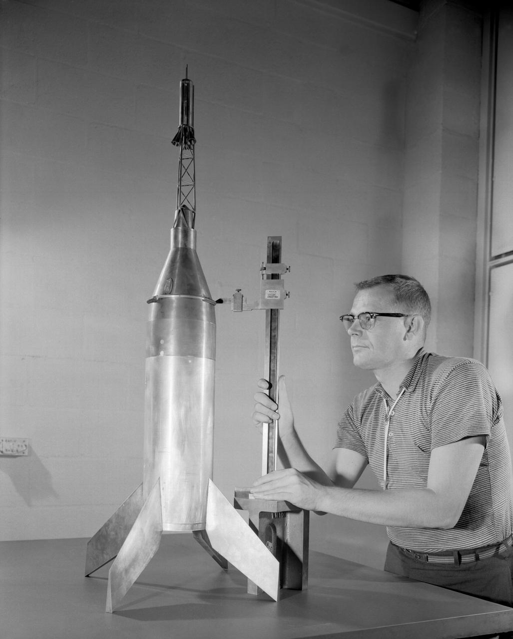
Publicity photograph of a technician measuring a wind tunnel model of the Little Joe test vehicle. Joseph Shortal noted that (vol. 3, p. 29): The largest project at Wallops in support of Mercury was the Little Joe project, designed to qualify the abort-escape system under flight conditions. James Hansen (p. 47) writes: STG engineers Max Faget and Paul Purser, then of Langley's PARD, had conceived Little Joe as a space capsule test vehicle even before the establishment of NASA and the formation of the STG. Girlruth understood the importance of the Little Joe tests: We had to be sure there were no serious performance and operational problems that we had simply not thought of in such a new and radical type of flight vehicle. -- Published in James R. Hansen, Spaceflight Revolution: NASA Langley Research Center From Sputnik to Apollo, (Washington: NASA, 1995), p. 47 Joseph A. Shortal, History of Wallops Station: Origins and Activities Through 1949, (Wallops Island, VA: National Aeronautics and Space Administration, Wallops Station, nd), Comment Edition.
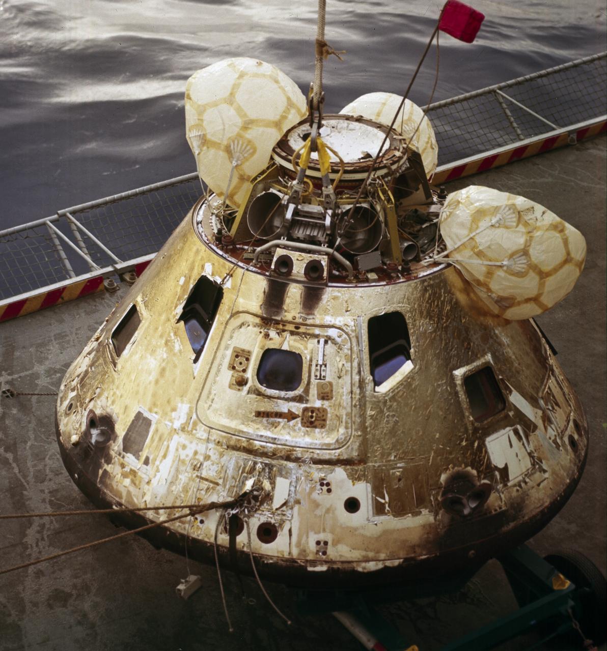
This is a photograph of the Apollo 8 Capsule being hoisted onto the recovery ship following splashdown on December 27, 1968. The first manned Apollo mission to escape Earth’s gravity and travel to the lunar vicinity, the Saturn V, SA-503, Apollo 8 mission liftoff occurred seven days prior, on December 21, 1968. Aboard were astronauts William Anders, Lunar Module (LM) Pilot; James Lovell, Command Module (CM) pilot; and Frank Borman, commander. The mission achieved operational experience and tested the Apollo command module systems, including communications, tracking, and life-support, in cis-lunar space and lunar orbit, and allowed evaluation of crew performance on a lunar orbiting mission. The crew photographed the lunar surface, both far side and near side, obtaining information on topography and landmarks as well as other scientific information necessary for future Apollo landings. All systems operated within allowable parameters and all objectives of the mission were achieved.
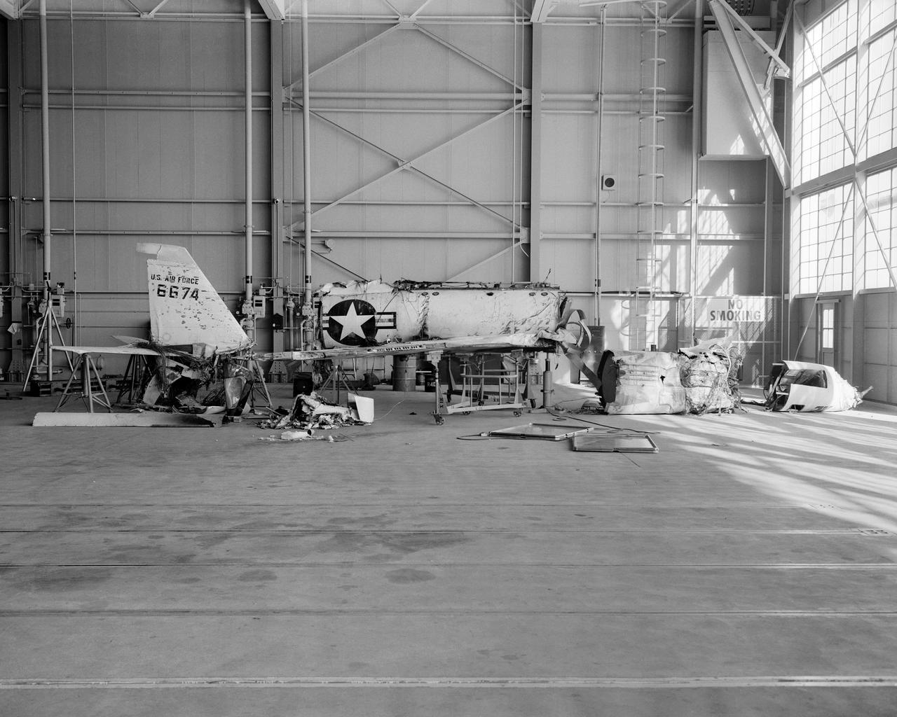
The X-2, initially an Air Force program, was scheduled to be transferred to the civilian National Advisory Committee for Aeronautics (NACA) for scientific research. The Air Force delayed turning the aircraft over to the NACA in the hope of attaining Mach 3 in the airplane. The service requested and received a two-month extension to qualify another Air Force test pilot, Capt. Miburn "Mel" Apt, in the X-2 and attempt to exceed Mach 3. After several ground briefings in the simulator, Apt (with no previous rocket plane experience) made his flight on 27 September 1956. Apt raced away from the B-50 under full power, quickly outdistancing the F-100 chase planes. At high altitude, he nosed over, accelerating rapidly. The X-2 reached Mach 3.2 (2,094 mph) at 65,000 feet. Apt became the first man to fly more than three times the speed of sound. Still above Mach 3, he began an abrupt turn back to Edwards. This maneuver proved fatal as the X-2 began a series of diverging rolls and tumbled out of control. Apt tried to regain control of the aircraft. Unable to do so, Apt separated the escape capsule. Too late, he attempted to bail out and was killed when the capsule impacted on the Edwards bombing range. The rest of the X-2 crashed five miles away. The wreckage of the X-2 rocket plane was later taken to NACA's High Speed Flight Station for analysis following the crash.
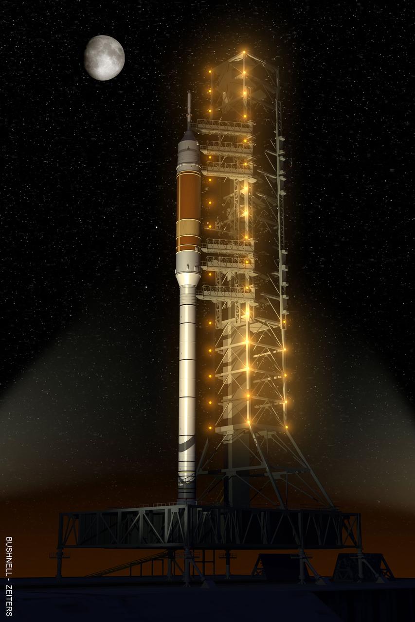
Under the goals of the Vision for Space Exploration, Ares I is a chief component of the cost-effective space transportation infrastructure being developed by NASA's Constellation Program. This transportation system will safely and reliably carry human explorers back to the moon, and then onward to Mars and other destinations in the solar system. Launch Pad 39B of the Kennedy Space Flight Center (KSC), currently used for Space Shuttle launches, will be revised to host the Ares launch vehicles. The fixed and rotating service structures standing at the pad will be dismantled sometime after the Ares I-X test flight. A new launch tower for Ares I will be built onto a new mobile launch platform. The gantry for the shuttle doesn't reach much higher than the top of the four segments of the solid rocket booster. Pad access above the current shuttle launch pad structure will not be required for Ares I-X because the stages above the solid rocket booster are inert. For the test scheduled in 2012 or for the crewed flights, workers and astronauts will need access to the highest levels of the rocket and capsule. When the Ares I rocket rolls out to the launch pad on the back of the same crawler-transporters used now, its launch gantry will be with it. The mobile launchers will nestle under three lightning protection towers to be erected around the pad area. Ares time at the launch pad will be significantly less than the three weeks or more the shuttle requires. This “clean pad” approach minimizes equipment and servicing at the launch pad. It is the same plan NASA used with the Saturn V rockets and industry employs it with more modern launchers. The launch pad will also get a new emergency escape system for astronauts, one that looks very much like a roller coaster. Cars riding on a rail will replace the familiar baskets hanging from steel cables. This artist's concept illustrates the Ares I on launch pad 39B.