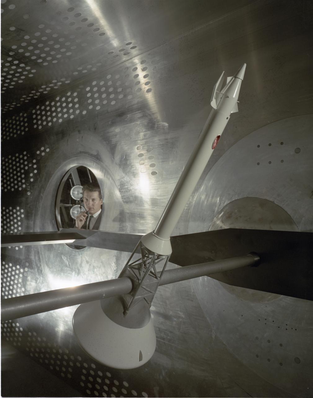
.059 SCALE MODEL OF APOLLO LAUNCH ESCAPE SYSTEM
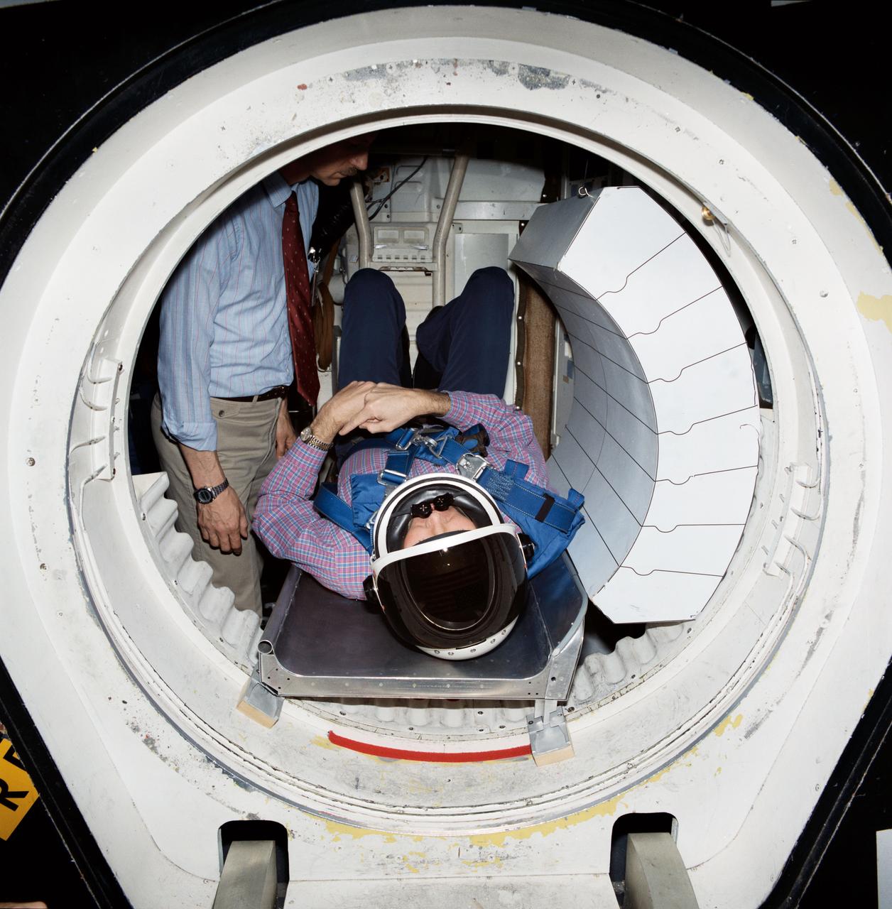
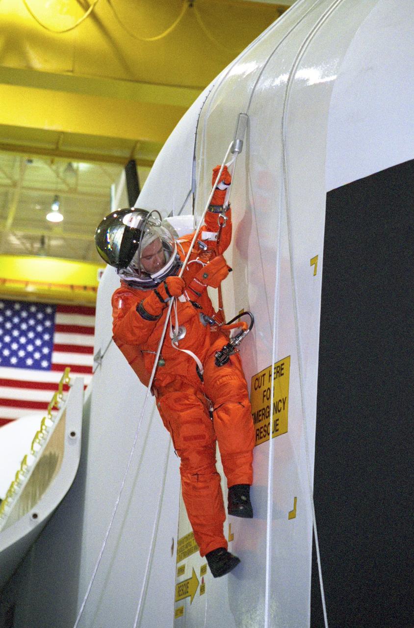
Shuttle crew escape systems test is conducted by astronauts Steven R. Nagel (left) and Manley L. (Sonny) Carter in JSC One Gravity Mockup and Training Facilities Bldg 9A crew compartment trainer (CCT). Nagel and Carter are evaluating methods for crew escape during Space Shuttle controlled gliding flight. JSC test was done in advance of tests scheduled for facilities in California and Utah. Here, Carter serves as test subject evaluating egress positioning for the tractor rocket escape method - one of the two systems currently being closely studied by NASA.
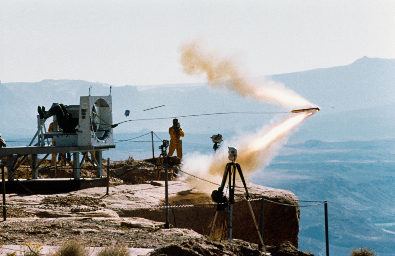
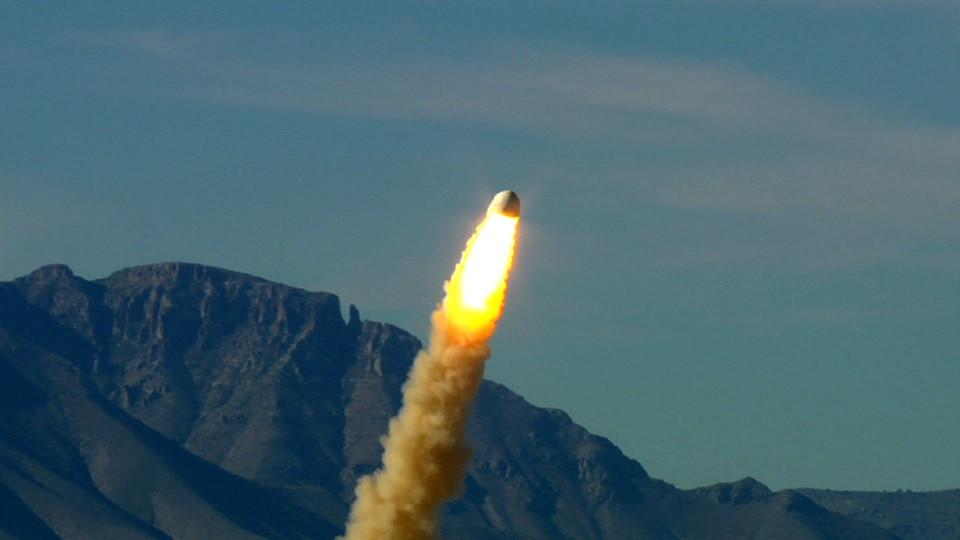
Shuttle crew escape systems (CES) tractor rocket tests conducted at Hurricane Mesa, Utah. This preliminary ground test of the tractor rocket will lead up to in-air evaluations. View shows tractor rocket as it is fired from side hatch mockup. The tractor rocket concept is one of two escape methods being studied to provide crew egress capability during Space Shuttle controlled gliding flight. In-air tests of the system, utilizing a Convair-240 aircraft, will begin 11-19-87 at the Naval Weapons Center in China Lake, California.
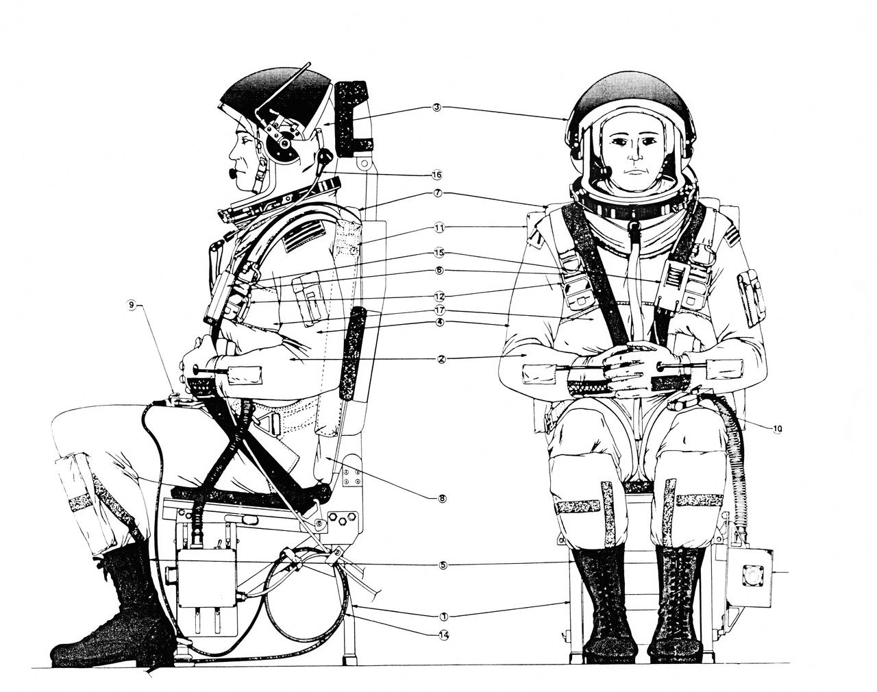
Diagrams of Crew Escape System Partial Pressure Suits, dated July, 1988.
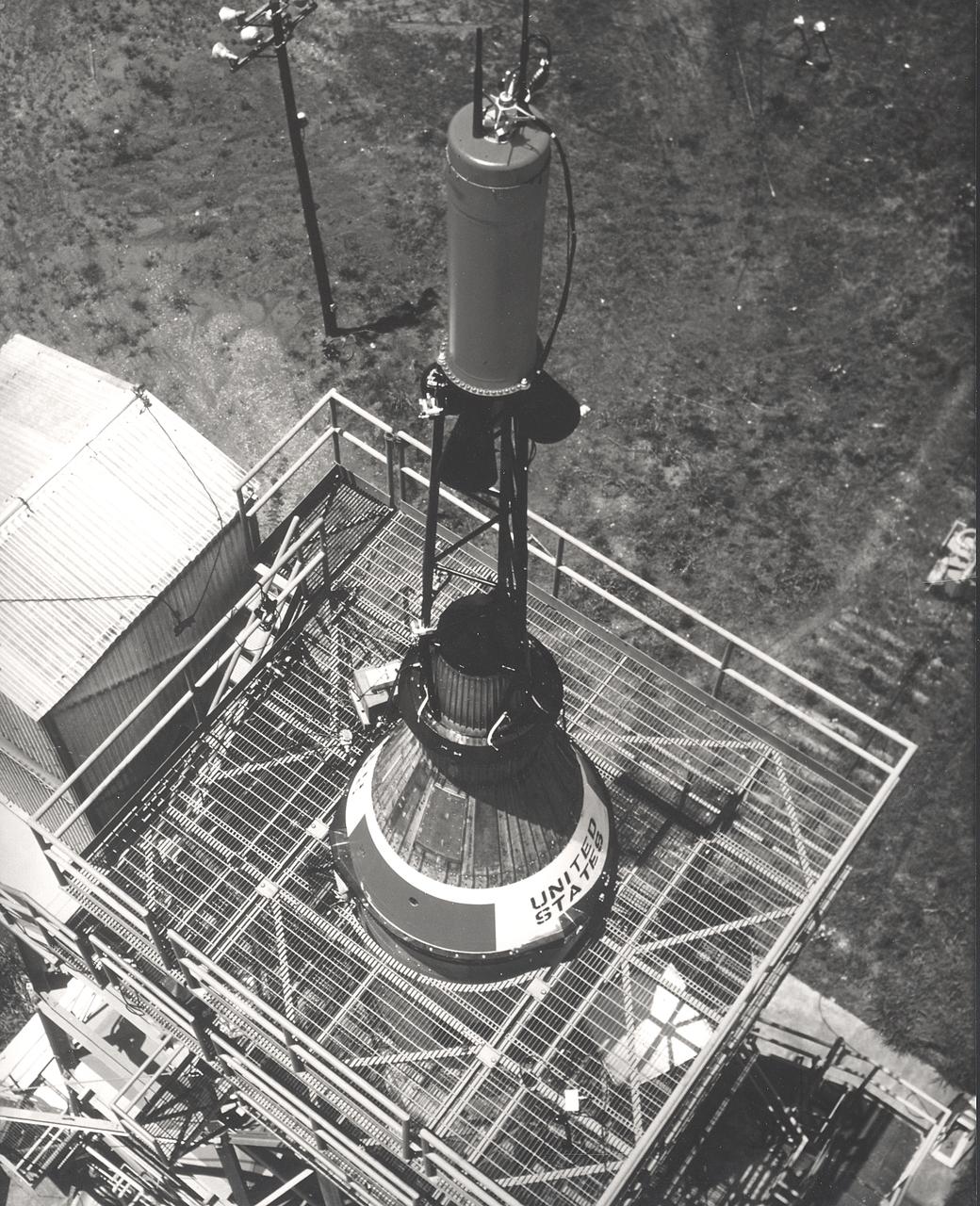
This photograph depicts installation of the Mercury capsule and escape system on top of a booster prior to test firing of the Mercury-Redstone launch vehicle at the Marshall Space Flight Center.
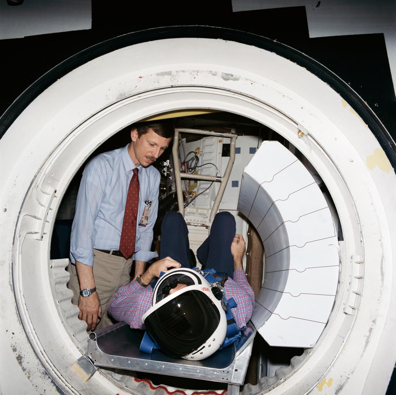
Shuttle crew escape systems test is conducted by astronauts Steven R. Nagel (left) and Manley L. (Sonny) Carter in JSC One Gravity Mockup and Training Facilities Bldg 9A crew compartment trainer (CCT). Nagel and Carter are evaluating methods for crew escape during Space Shuttle controlled gliding flight. JSC test was done in advance of tests scheduled for facilities in California and Utah. Here, Carter serves as test subject evaluating egress positioning for the tractor rocket escape method - one of the two systems currently being closely studied by NASA.

Shuttle crew escape systems test is conducted by astronauts Steven R. Nagel (left) and Manley L. (Sonny) Carter in JSC One Gravity Mockup and Training Facilities Bldg 9A crew compartment trainer (CCT). Nagel and Carter are evaluating methods for crew escape during Space Shuttle controlled gliding flight. JSC test was done in advance of tests scheduled for facilities in California and Utah. Here, Carter serves as test subject evaluating egress positioning for the tractor rocket escape method - one of the two systems currently being closely studied by NASA.
Photos of orbiter fire rescue and crew escape training for extravehicular activity (EVA) crew systems support conducted in Bldg 9A Crew Compartment Trainer (CCT) and Fuel Fuselage Trainer (FFT) include views of CCT interior of middeck starboard fuselage showing middeck forward (MF) locker and COAS assembly filter, artiflex film and camcorder bag (26834); launch/entry suit (LES) helmet assembly, neckring and helmet hold-down assembly (26835-26836); middeck aft (MA) lockers (26837); area of middeck airlock and crew escape pole (26838); connectors of crew escape pole in the middeck (268390); three test subjects in LES in the flight deck (26840); emergency side hatch slide before inflated stowage (26841); area of below adjacent to floor panel MD23R (26842); a test subject in LES in the flight deck (26843); control board and also showing sign of "orbital maneuvering system (OMS) secure and OMS TK" (26844); test subject in the flight deck also showing chart of "ascent/abort summary" (26845).
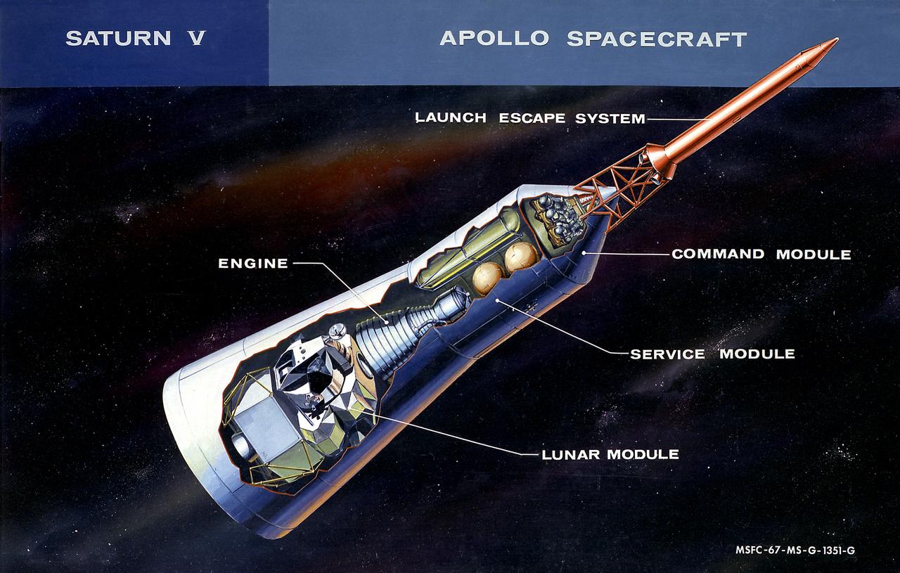
This cutaway illustration shows the Apollo Spacecraft with callouts of the major components. The spacecraft consisted of the lunar module, the service module, the command module, and the launch escape system.
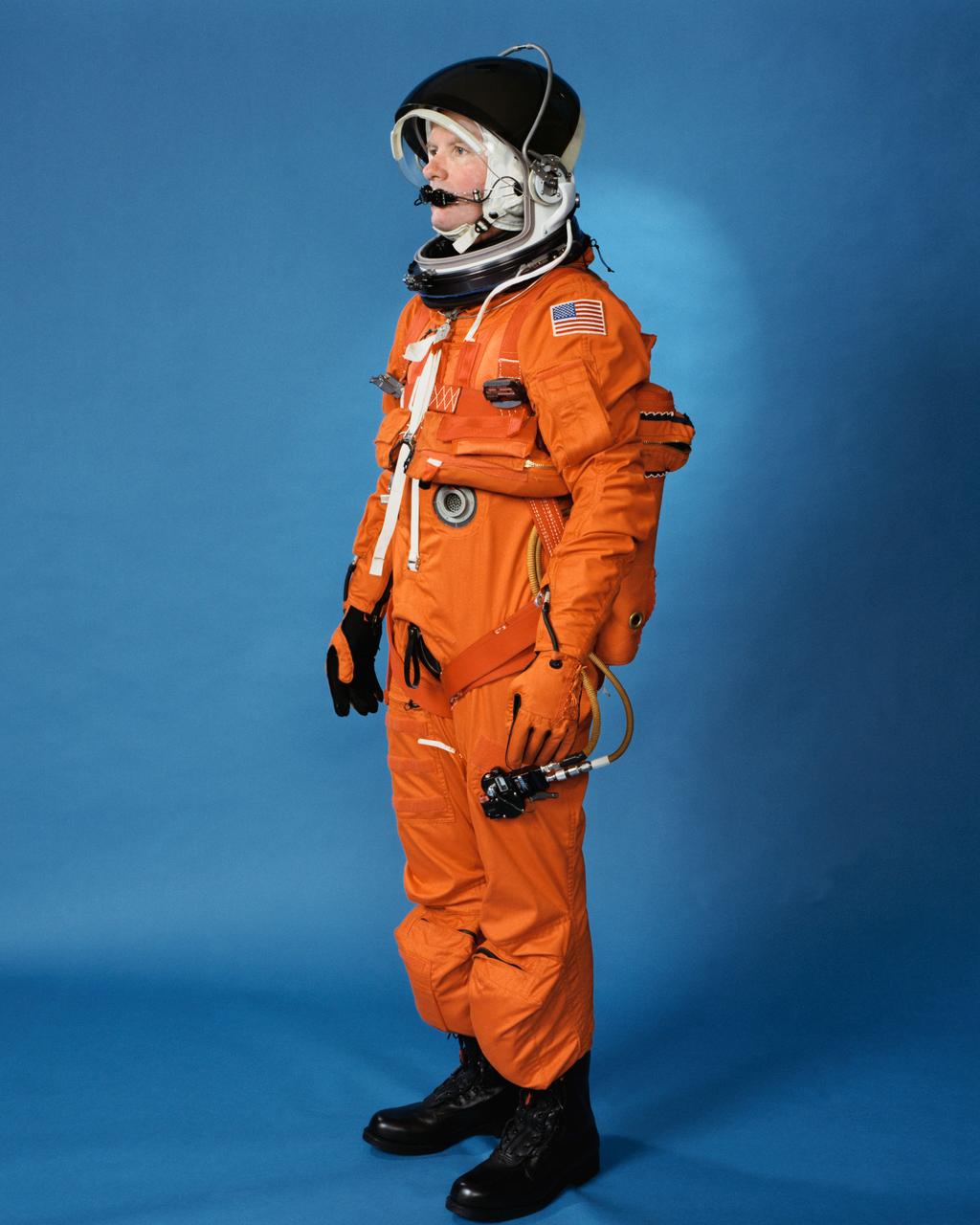
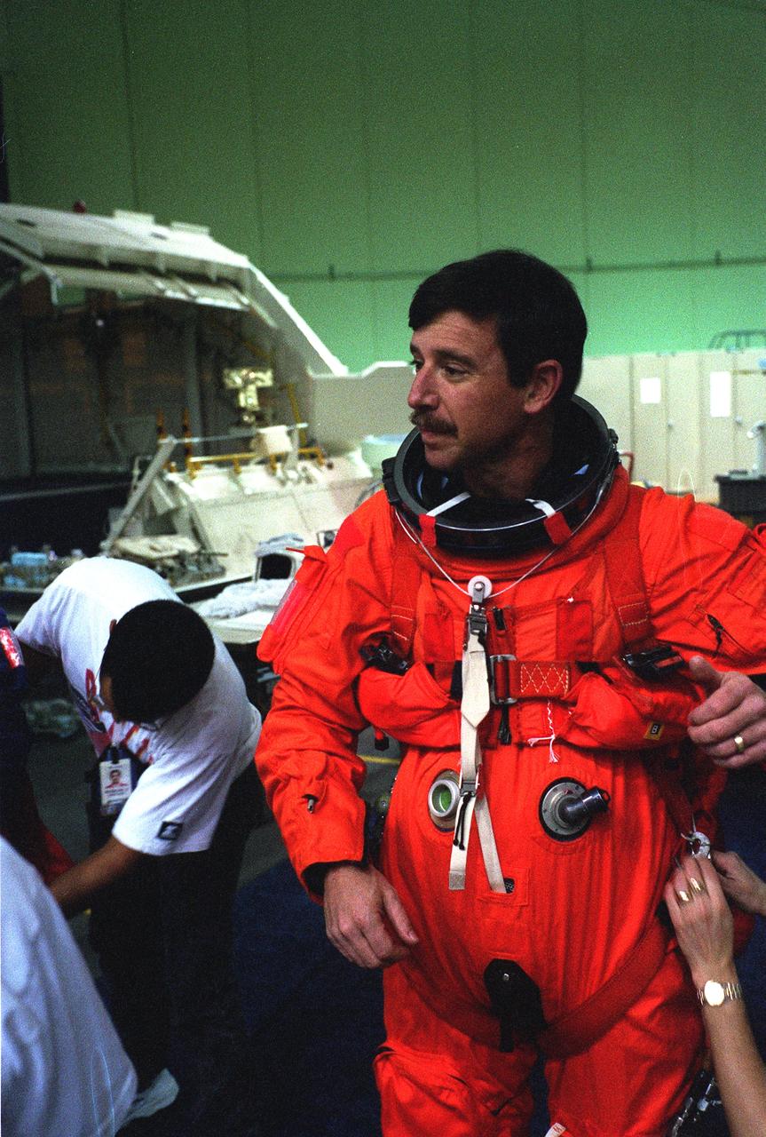
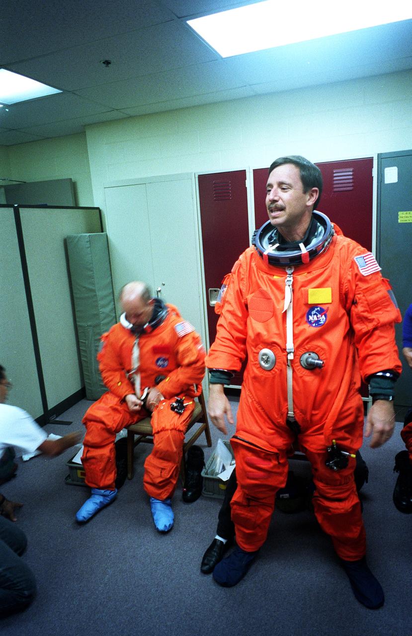
Space shuttle orange launch and entry suit (LES), a partial pressure suit, is modeled by a technician. LES was designed for STS-26, the return to flight mission, and subsequent missions. Included in the crew escape system (CES) package are launch and entry helmet (LEH) with communications carrier (COMM CAP), parachute pack and harness, life raft, life preserver unit (LPU), LES gloves, suit oxygen manifold and valves, boots, and survival gear.
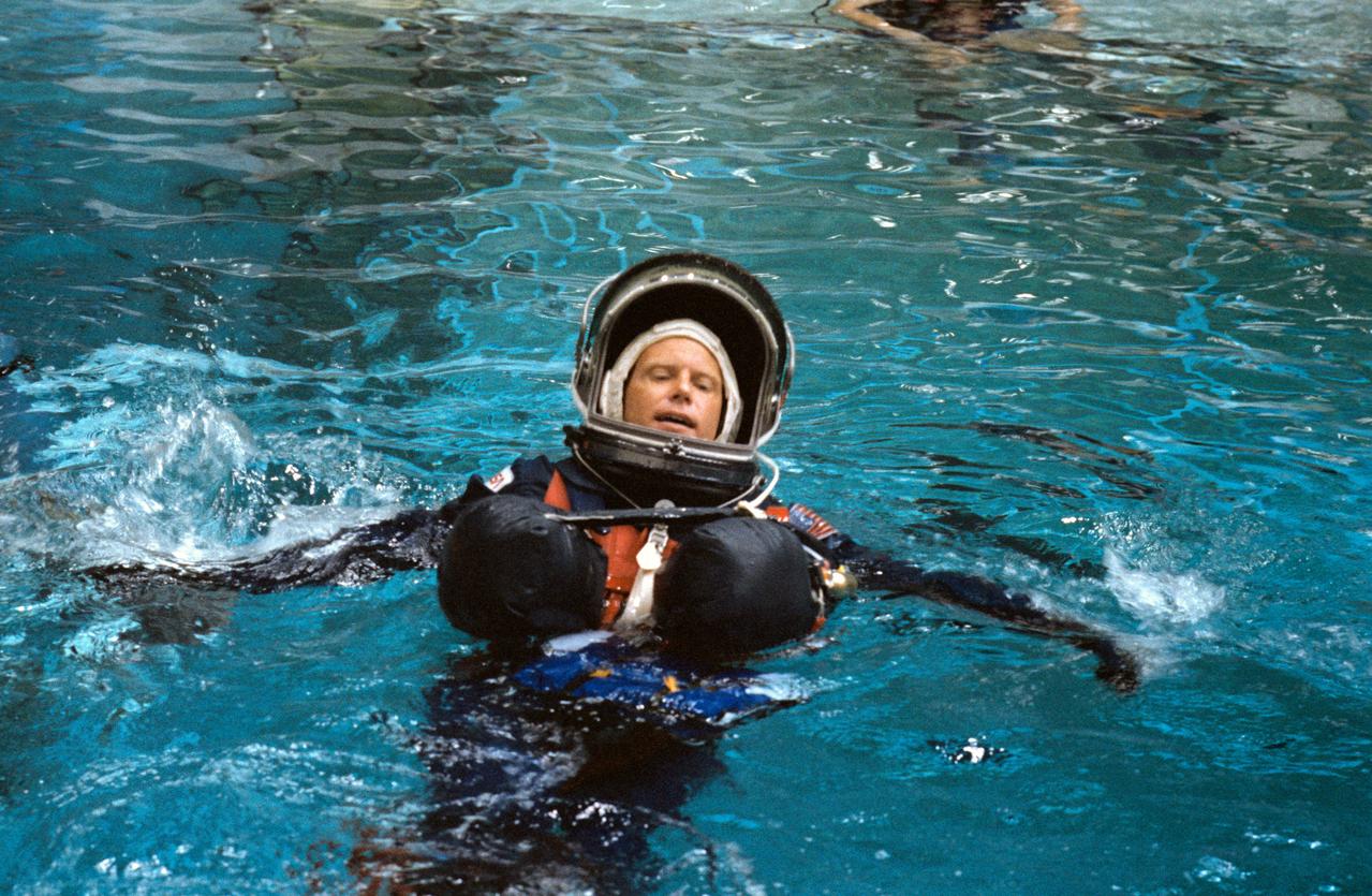
S88-42409 (20 July 1988) --- STS-26 Discovery, Orbiter Vehicle (OV) 103, Mission Specialist (MS) George D. Nelson participates in crew escape system (CES) testing in JSC Weightless Environment Training Facility (WETF) Bldg 29. Nelson, wearing the newly designed (navy blue) launch and entry suit (LES), floats in WETF pool with the aid of an underarm flotation device (modern version of Mas West floats). He awaits the assistance of SCUBA-equipped divers during a simulation of escape and rescue operations utilizing a new CES pole for emergency exit from the Space Shuttle.
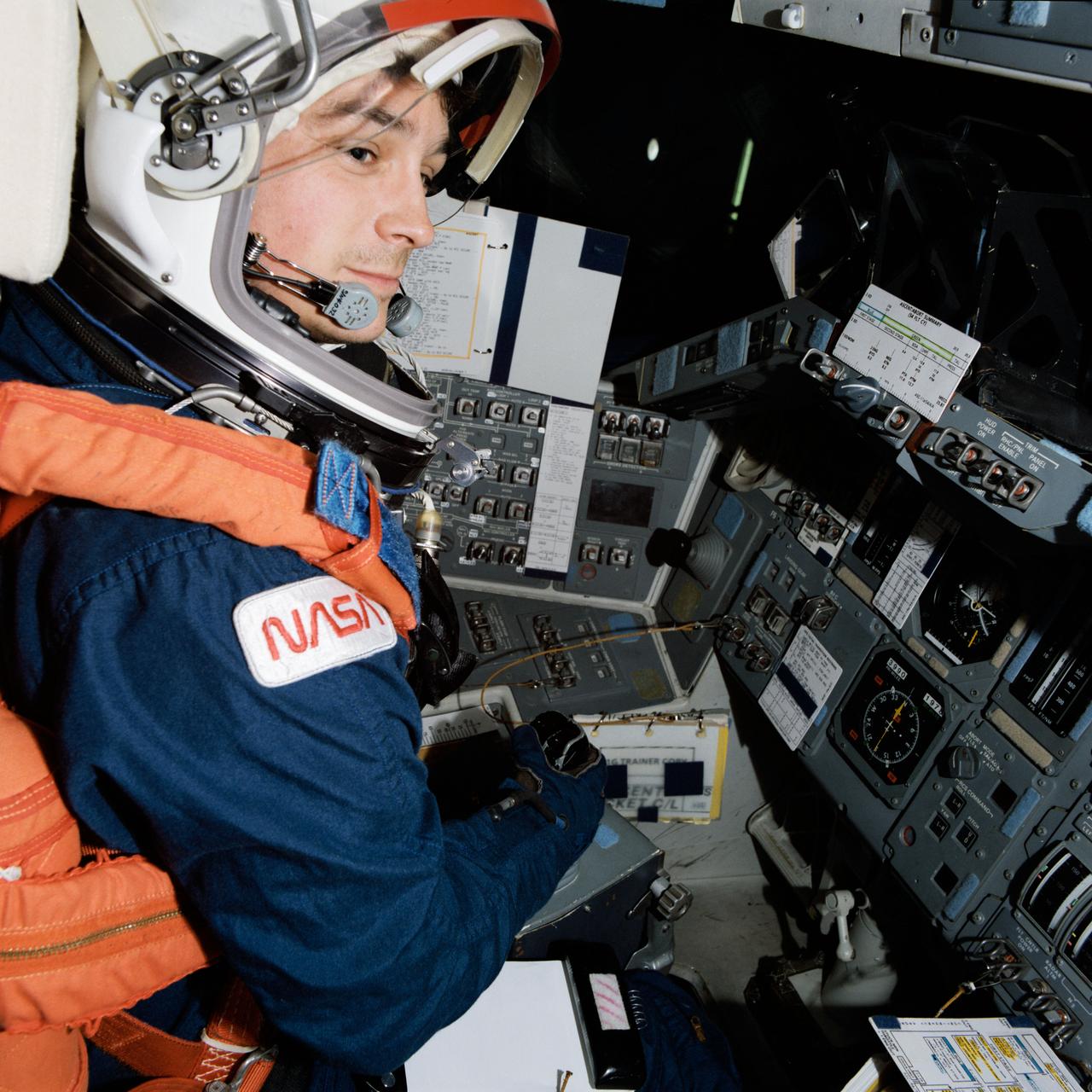
Astronaut Kenneth S. Reightler, pilot for the STS-60 mission, prepares to simulate egress from a troubled Space Shuttle using Crew Escape System (CES) pole. The action came during emergency egress training in JSC's Shuttle mockup and integration laboratory.
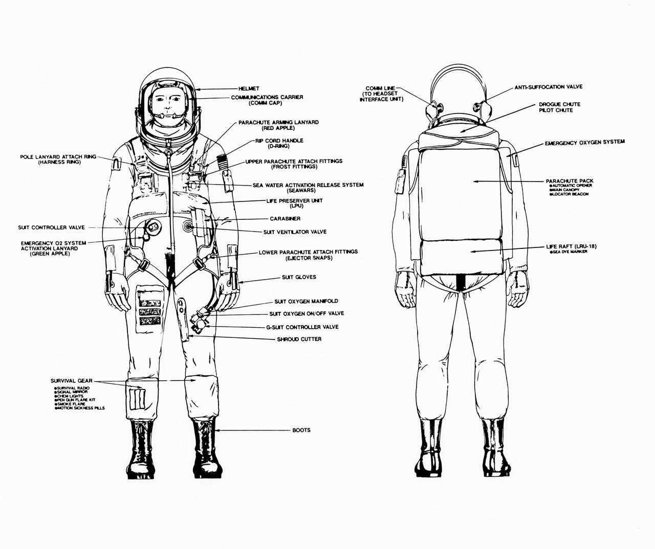
Line drawings illustrate the front and back of the space shuttle launch and entry suit (LES) and labels identify various components. LES was designed for STS-26, the return to flight mission, and subsequent missions. Included in the crew escape system (CES) package are launch and entry helmet (LEH) with communications carrier (COMM CAP), parachute pack and harness, life preserver unit (LPU), life raft unit (LRU), LES gloves, suit oxygen manifold and valves, boots, and survival gear. Details of larger components are also identified.
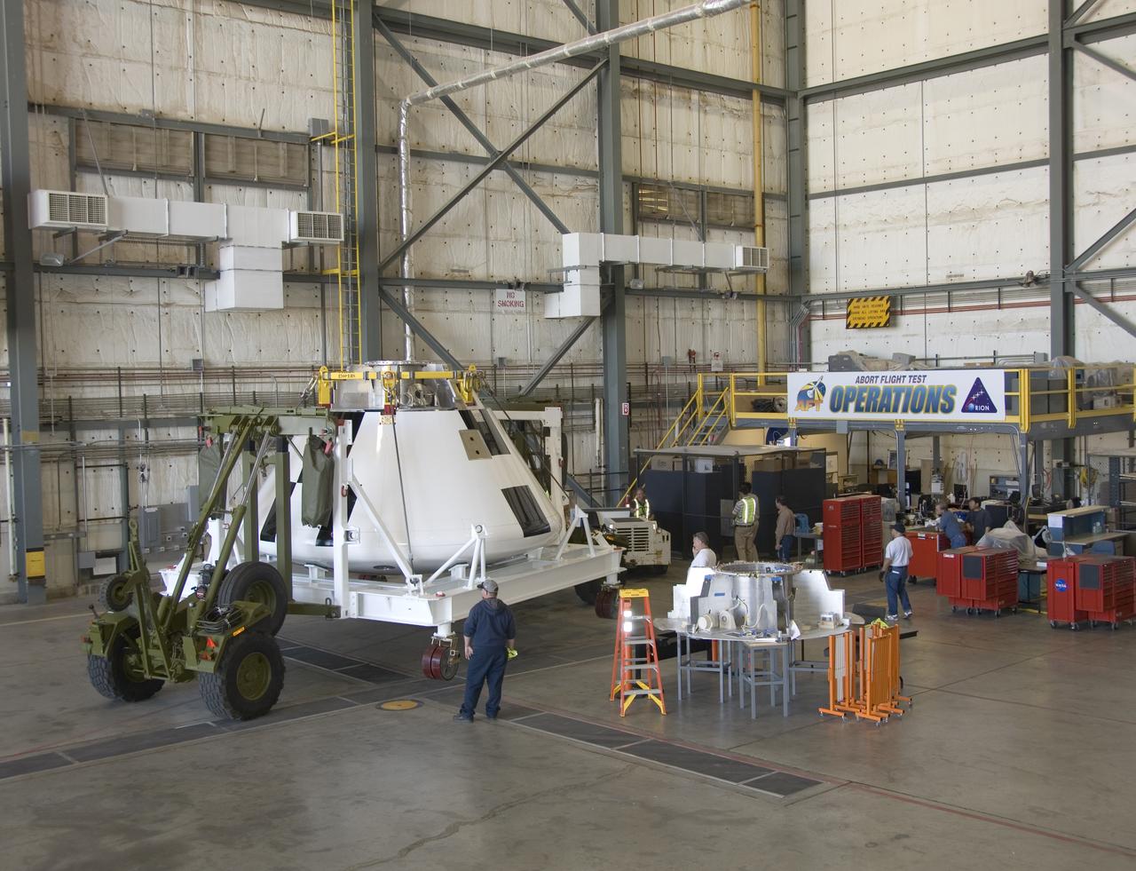
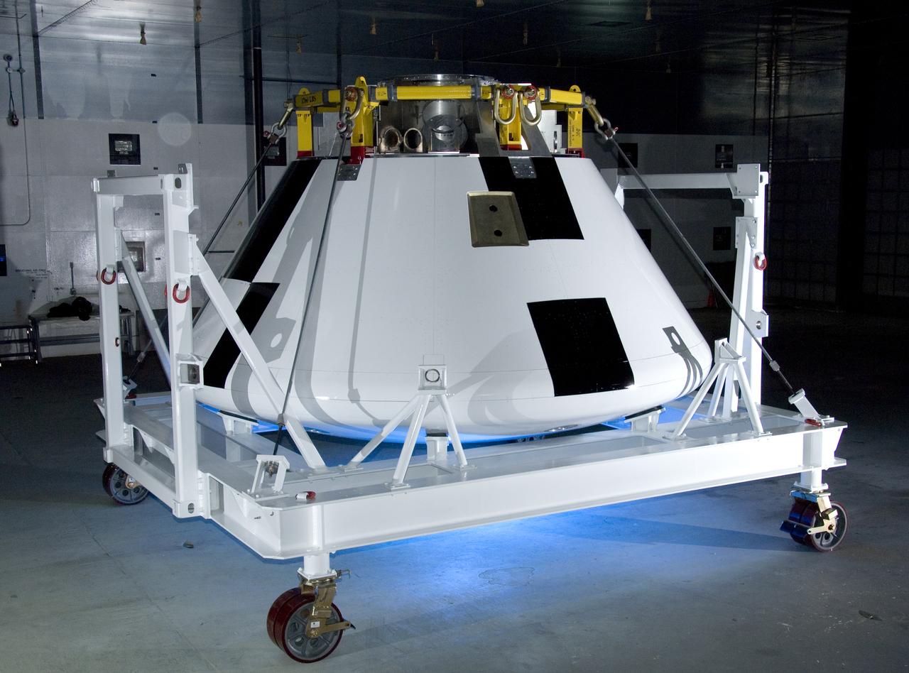
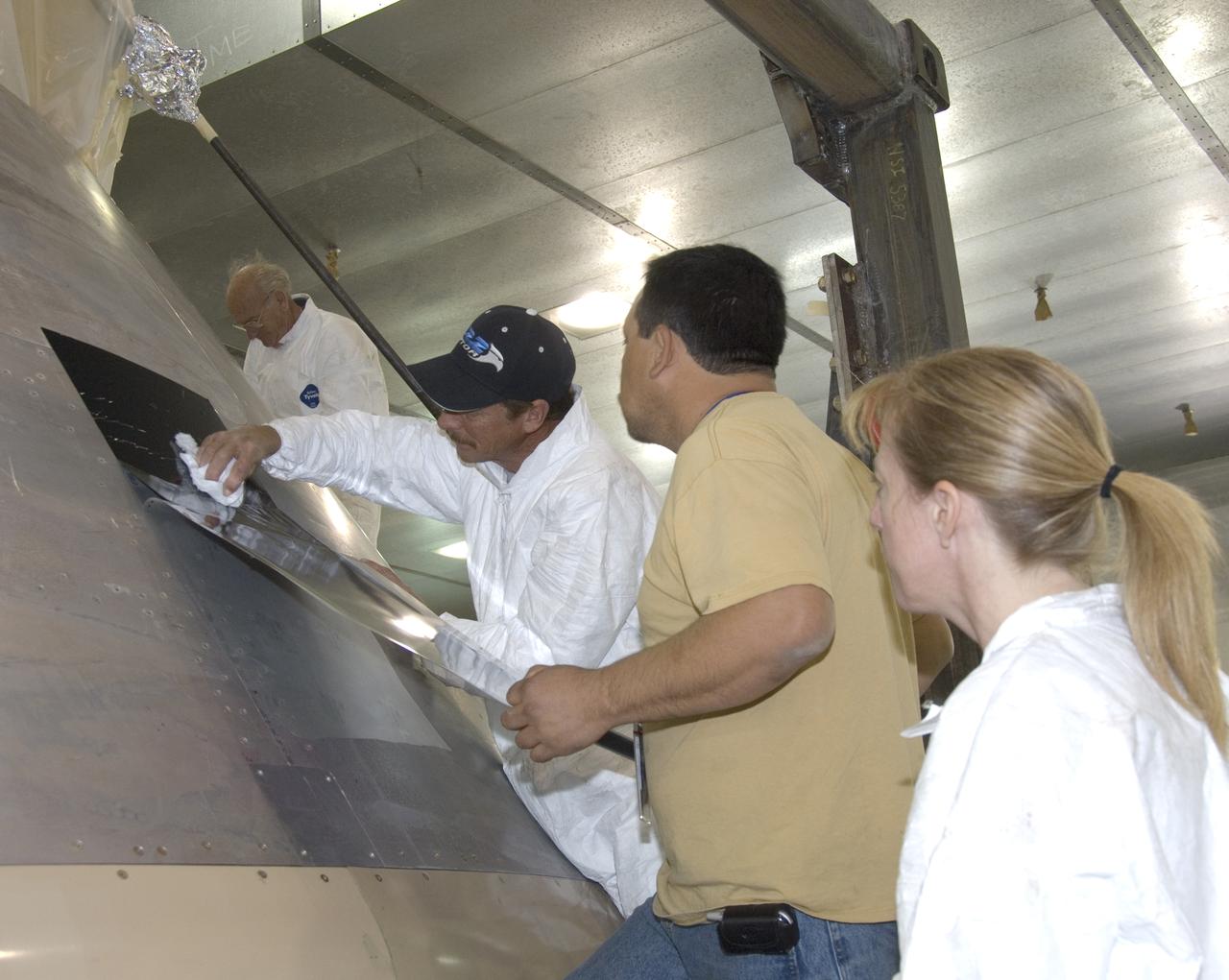
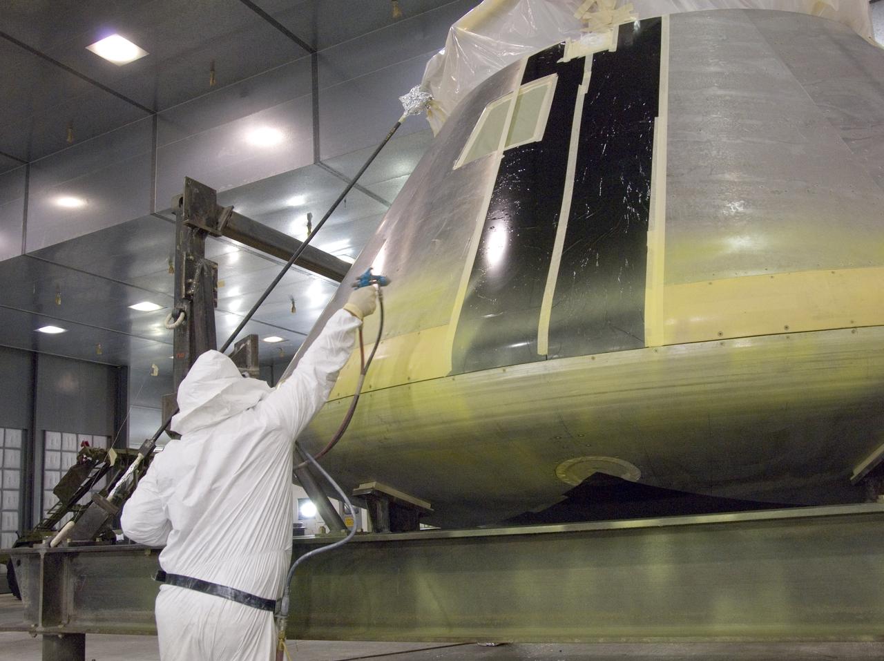
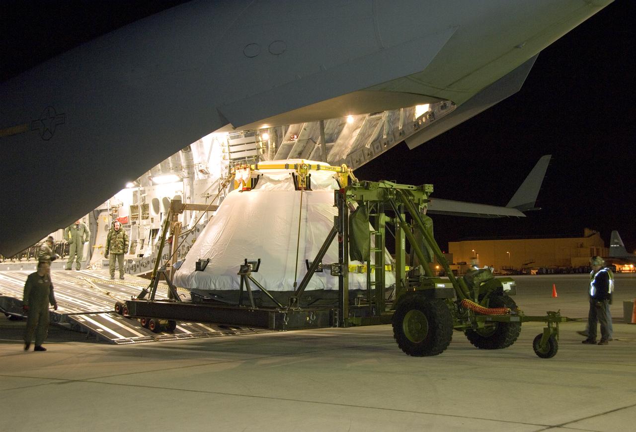
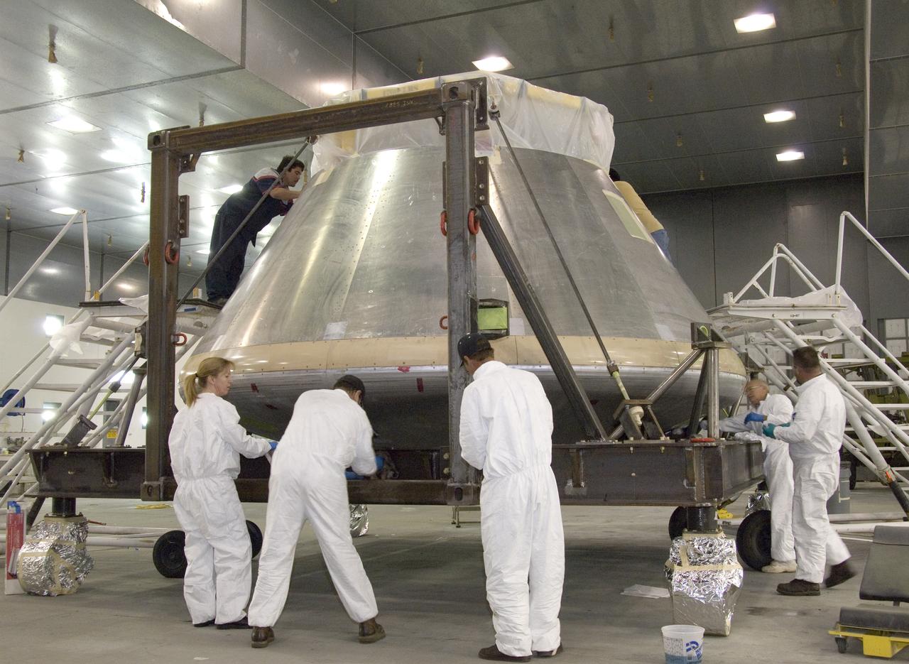
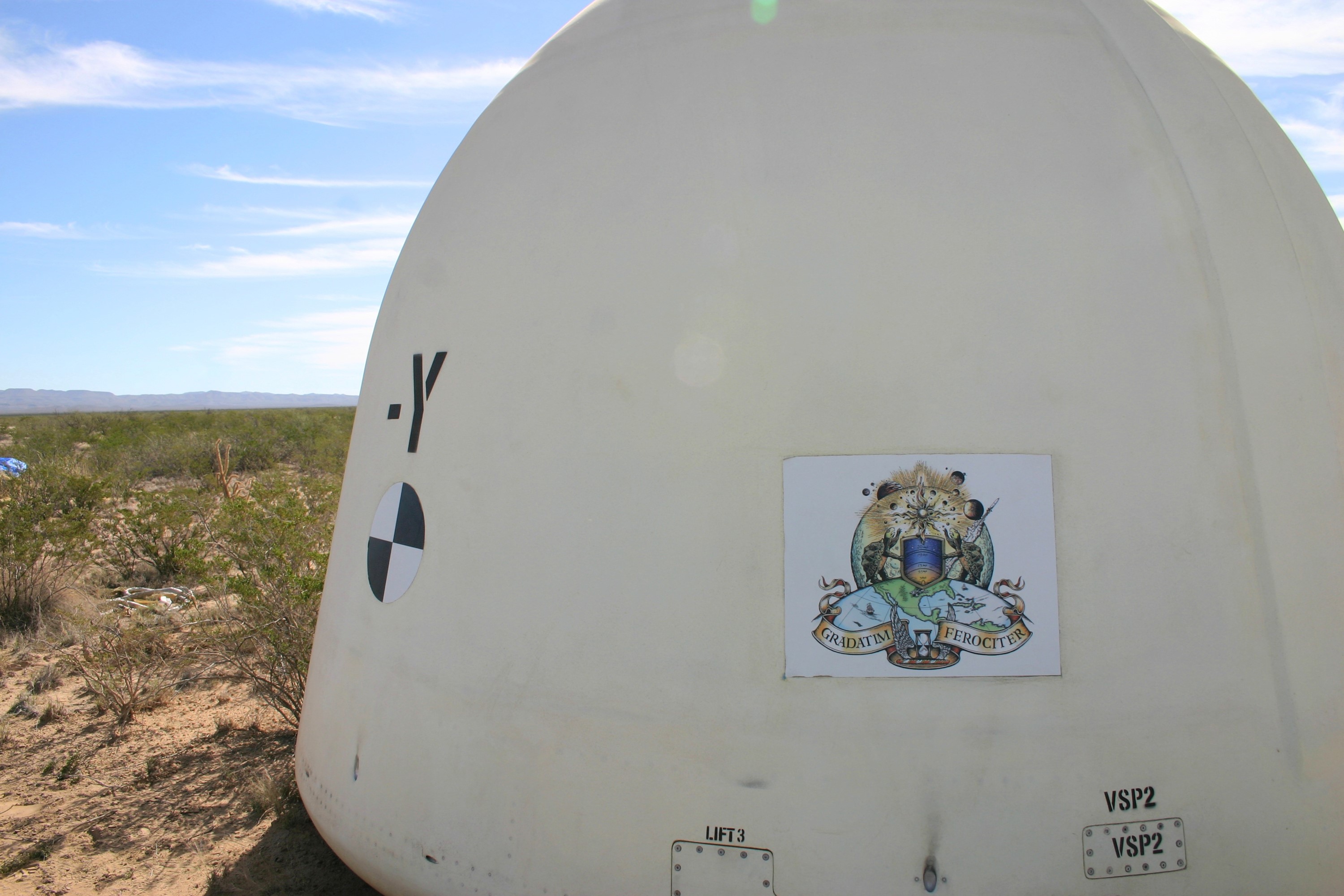
A full-scale flight-test mockup of the Constellation program's Orion crew vehicle arrived at NASA's Dryden Flight Research Center in late March 2008 to undergo preparations for the first short-range flight test of the spacecraft's astronaut escape system later that year. Engineers and technicians at NASA's Langley Research Center fabricated the structure, which precisely represents the size, outer shape and mass characteristics of the Orion space capsule. The Orion crew module mockup was ferried to NASA Dryden on an Air Force C-17. After painting in the Edwards Air Force Base paint hangar, the conical capsule was taken to Dryden for installation of flight computers, instrumentation and other electronics prior to being sent to the U.S. Army's White Sands Missile Range in New Mexico for integration with the escape system and the first abort flight test in late 2008. The tests were designed to ensure a safe, reliable method of escape for astronauts in case of an emergency.
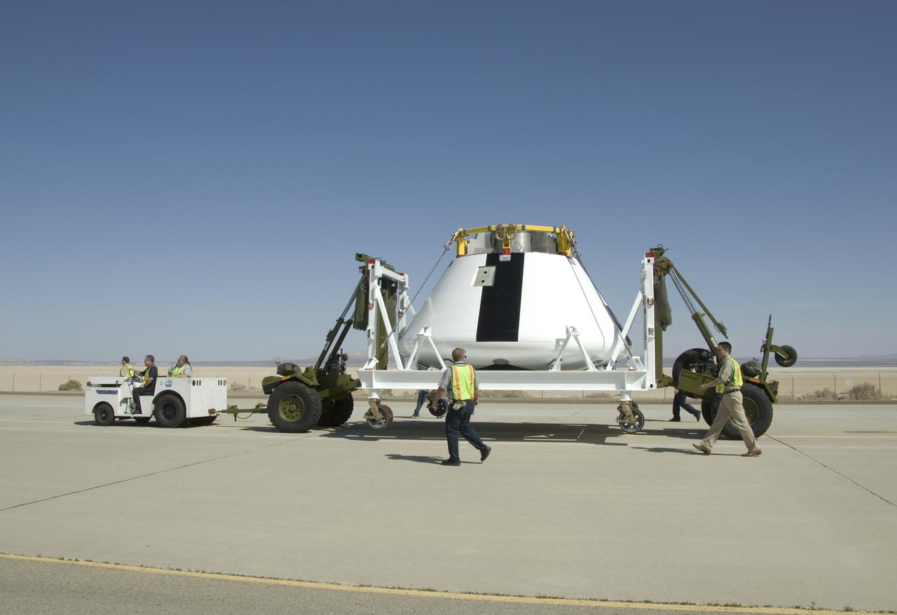
A full-scale flight-test mockup of the Constellation program's Orion crew vehicle arrived at NASA's Dryden Flight Research Center in late March 2008 to undergo preparations for the first short-range flight test of the spacecraft's astronaut escape system later that year. Engineers and technicians at NASA's Langley Research Center fabricated the structure, which precisely represents the size, outer shape and mass characteristics of the Orion space capsule. The Orion crew module mockup was ferried to NASA Dryden on an Air Force C-17. After painting in the Edwards Air Force Base paint hangar, the conical capsule was taken to Dryden for installation of flight computers, instrumentation and other electronics prior to being sent to the U.S. Army's White Sands Missile Range in New Mexico for integration with the escape system and the first abort flight test in late 2008. The tests were designed to ensure a safe, reliable method of escape for astronauts in case of an emergency.
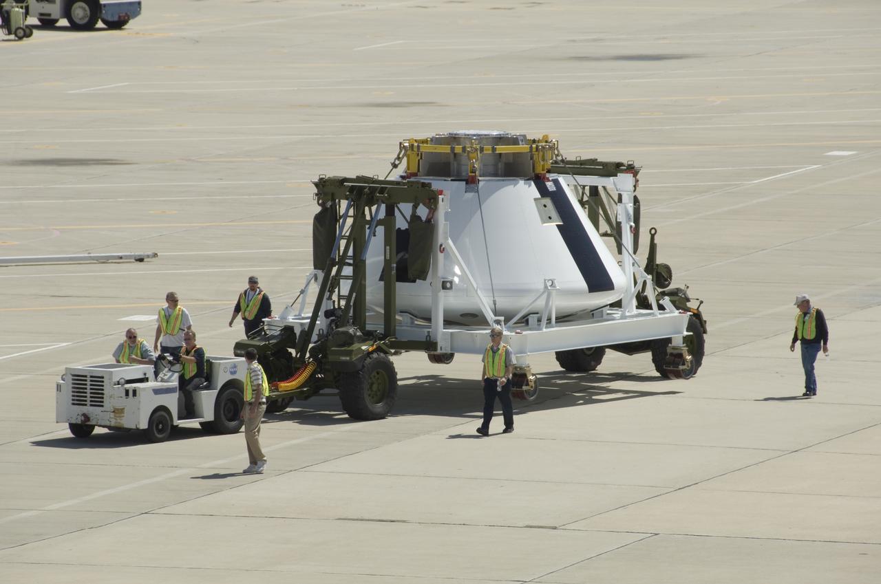
A full-scale flight-test mockup of the Constellation program's Orion crew vehicle arrived at NASA's Dryden Flight Research Center in late March 2008 to undergo preparations for the first short-range flight test of the spacecraft's astronaut escape system later that year. Engineers and technicians at NASA's Langley Research Center fabricated the structure, which precisely represents the size, outer shape and mass characteristics of the Orion space capsule. The Orion crew module mockup was ferried to NASA Dryden on an Air Force C-17. After painting in the Edwards Air Force Base paint hangar, the conical capsule was taken to Dryden for installation of flight computers, instrumentation and other electronics prior to being sent to the U.S. Army's White Sands Missile Range in New Mexico for integration with the escape system and the first abort flight test in late 2008. The tests were designed to ensure a safe, reliable method of escape for astronauts in case of an emergency.
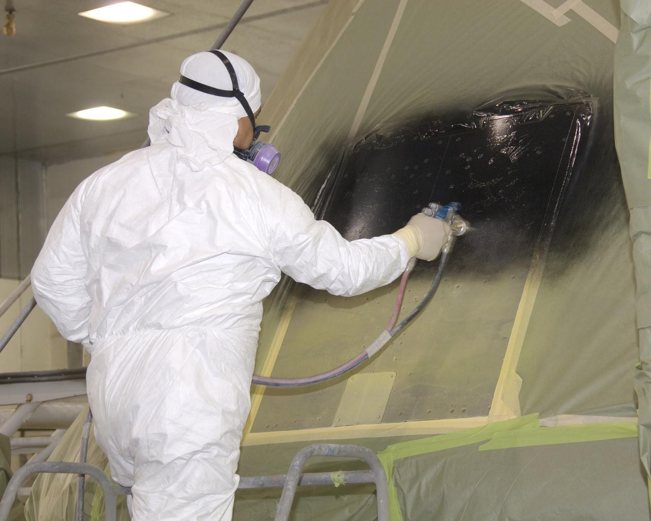
A full-scale flight-test mockup of the Constellation program's Orion crew vehicle arrived at NASA's Dryden Flight Research Center in late March 2008 to undergo preparations for the first short-range flight test of the spacecraft's astronaut escape system later that year. Engineers and technicians at NASA's Langley Research Center fabricated the structure, which precisely represents the size, outer shape and mass characteristics of the Orion space capsule. The Orion crew module mockup was ferried to NASA Dryden on an Air Force C-17. After painting in the Edwards Air Force Base paint hangar, the conical capsule was taken to Dryden for installation of flight computers, instrumentation and other electronics prior to being sent to the U.S. Army's White Sands Missile Range in New Mexico for integration with the escape system and the first abort flight test in late 2008. The tests were designed to ensure a safe, reliable method of escape for astronauts in case of an emergency.
A full-scale flight-test mockup of the Constellation program's Orion crew vehicle arrived at NASA's Dryden Flight Research Center in late March 2008 to undergo preparations for the first short-range flight test of the spacecraft's astronaut escape system later that year. Engineers and technicians at NASA's Langley Research Center fabricated the structure, which precisely represents the size, outer shape and mass characteristics of the Orion space capsule. The Orion crew module mockup was ferried to NASA Dryden on an Air Force C-17. After painting in the Edwards Air Force Base paint hangar, the conical capsule was taken to Dryden for installation of flight computers, instrumentation and other electronics prior to being sent to the U.S. Army's White Sands Missile Range in New Mexico for integration with the escape system and the first abort flight test in late 2008. The tests were designed to ensure a safe, reliable method of escape for astronauts in case of an emergency.
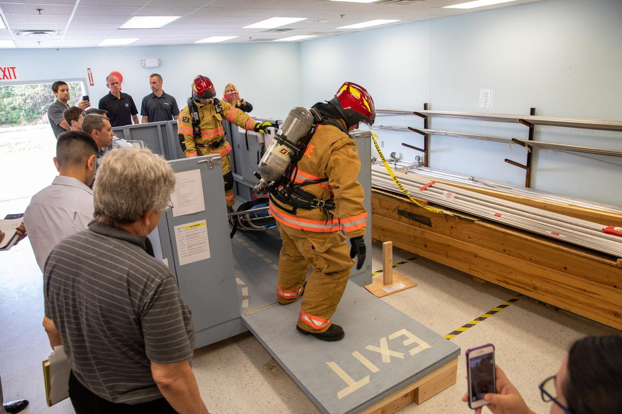
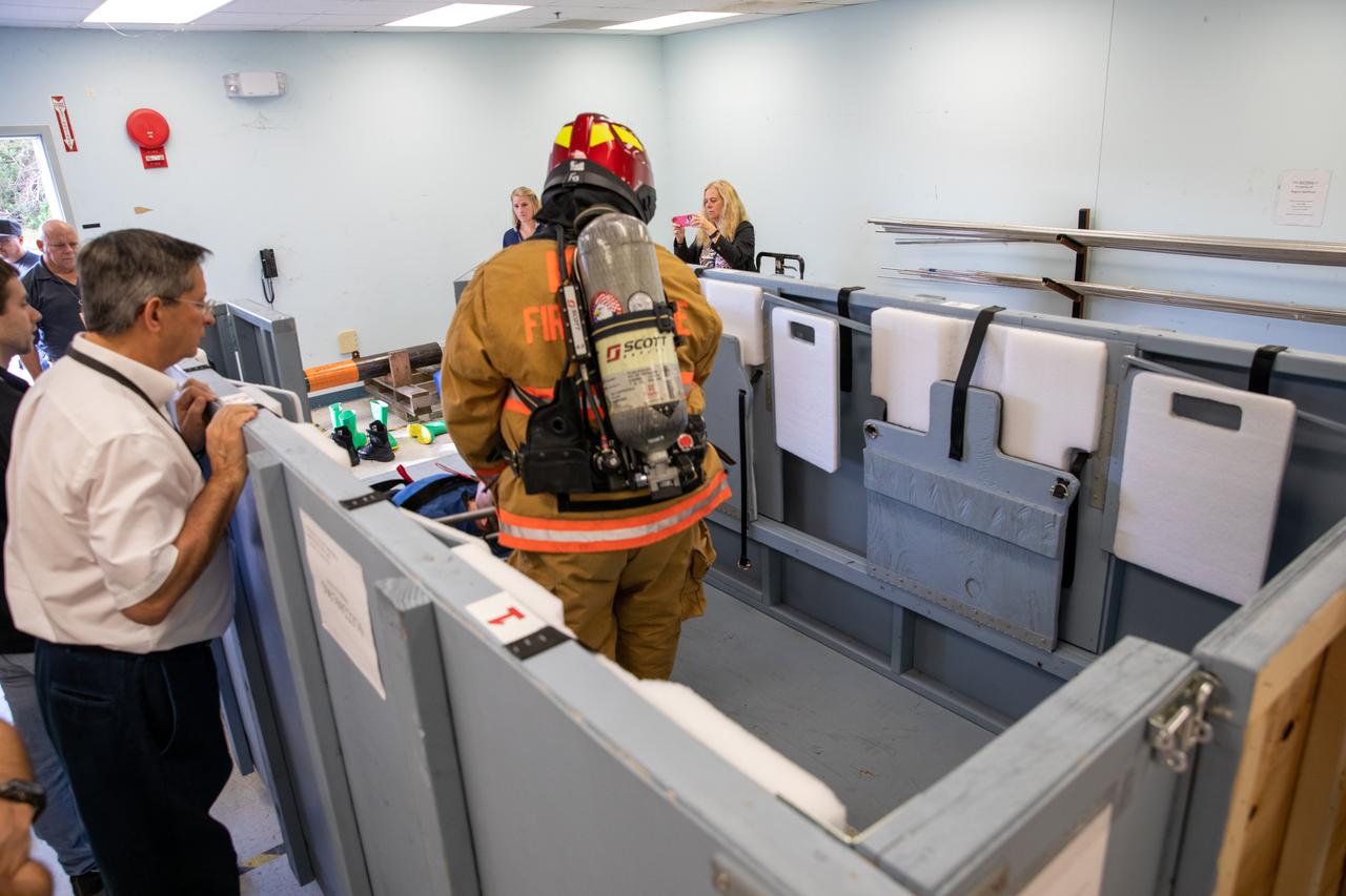
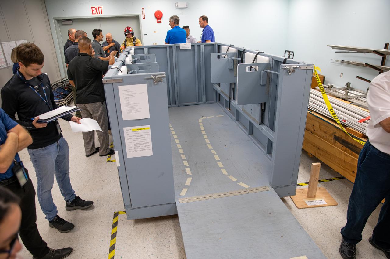
Members of NASA Kennedy Space Center’s Fire Rescue team conduct a series of trial scenarios in a mock-up of a launch pad escape basket on Feb. 19, 2020. Kennedy’s prime contractor Reynolds, Smith and Hill presented the mock-up to NASA, Kennedy Fire Rescue personnel and other stakeholders at the Florida spaceport. The basket would be utilized at Launch Pad 39B in the unlikely event of an emergency at the pad requiring evacuation during crewed missions under the Artemis Program. The actual egress basket will be designed larger than ones used during the shuttle era in order to accommodate fire rescue crew, astronauts and closeout crew. During the presentation, items such as basket release location, seat depth to accommodate firefighters in full gear, sequence of loading and more were addressed. Engineers will take what they learned during this presentation and discussion to advance the design of the pad egress system.
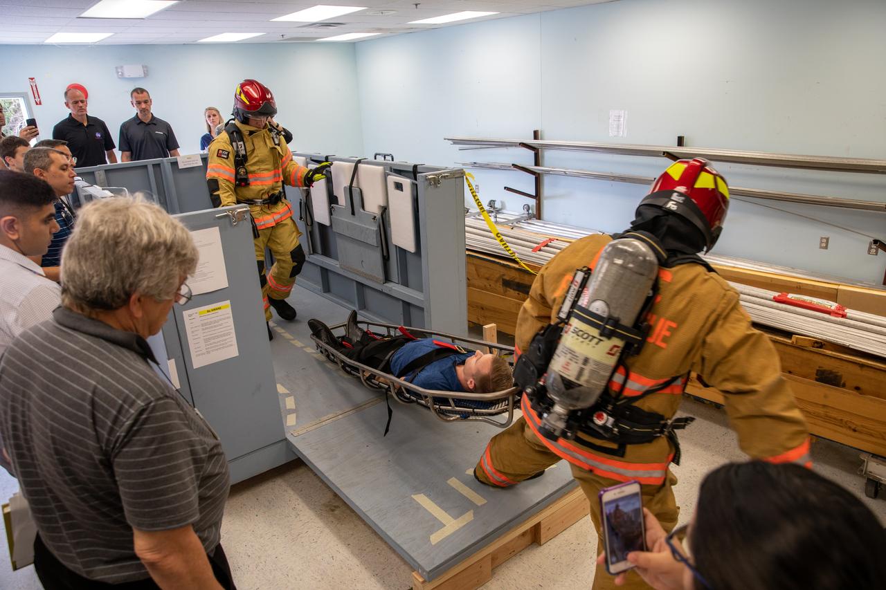
Members of NASA Kennedy Space Center’s Fire Rescue team conduct a series of trial scenarios in a mock-up of a launch pad escape basket on Feb. 19, 2020. Kennedy’s prime contractor Reynolds, Smith and Hill presented the mock-up to NASA, Kennedy Fire Rescue personnel and other stakeholders at the Florida spaceport. The basket would be utilized at Launch Pad 39B in the unlikely event of an emergency at the pad requiring evacuation during crewed missions under the Artemis Program. The actual egress basket will be designed larger than ones used during the shuttle era in order to accommodate fire rescue crew, astronauts and closeout crew. During the presentation, items such as basket release location, seat depth to accommodate firefighters in full gear, sequence of loading and more were addressed. Engineers will take what they learned during this presentation and discussion to advance the design of the pad egress system.
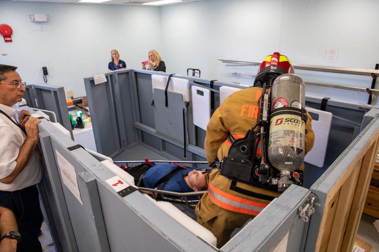
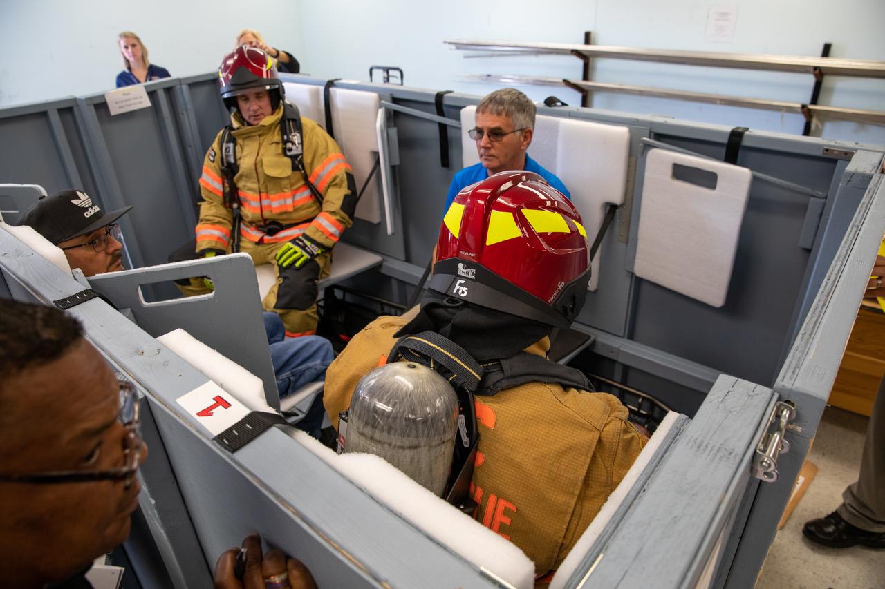
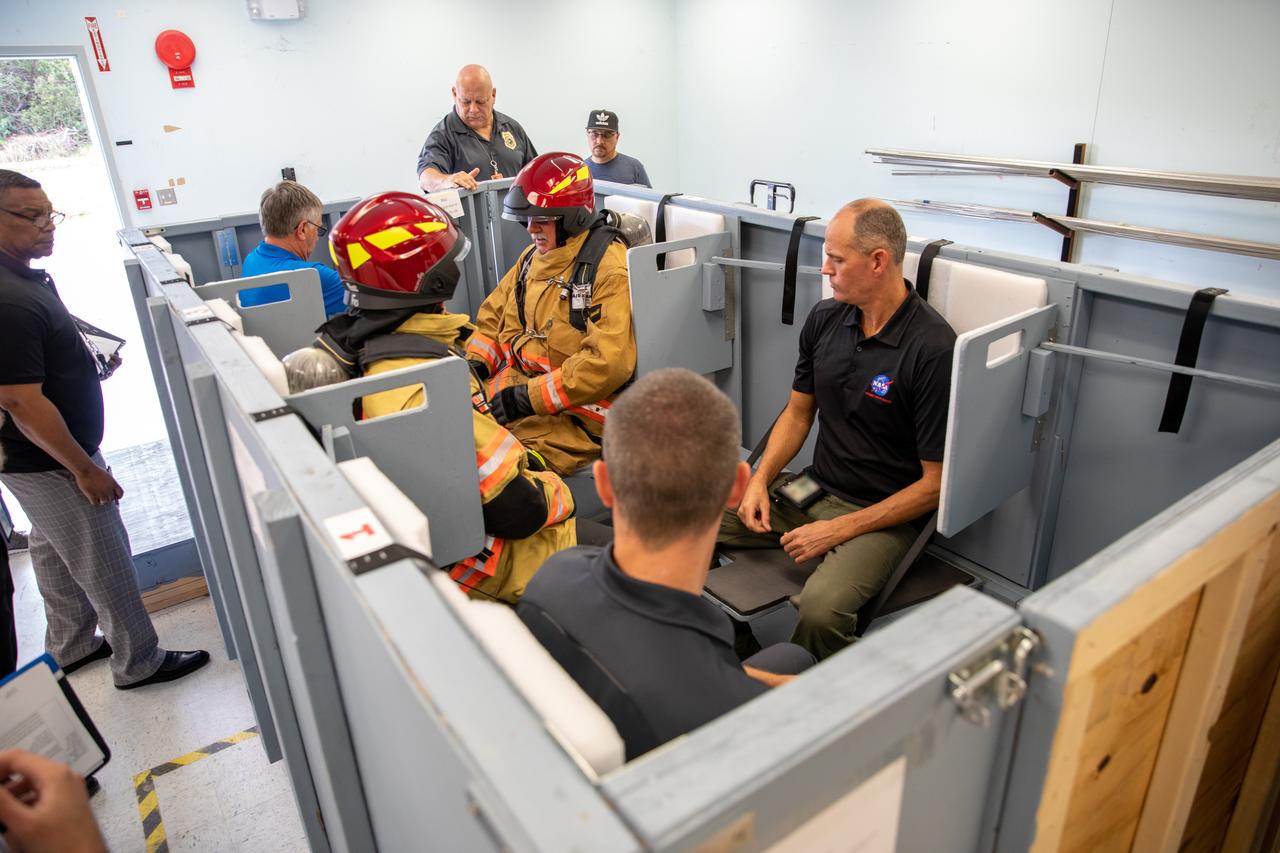
Members of NASA Kennedy Space Center’s Fire Rescue team participate in a series of trial scenarios in a mock-up of a launch pad escape basket on Feb. 19, 2020. Kennedy’s prime contractor Reynolds, Smith and Hill presented the mock-up to NASA, Kennedy Fire Rescue personnel and other stakeholders at the Florida spaceport. The basket would be utilized at Launch Pad 39B in the unlikely event of an emergency at the pad requiring evacuation during crewed missions under the Artemis Program. The actual egress basket will be designed larger than ones used during the shuttle era in order to accommodate fire rescue crew, astronauts and closeout crew. During the presentation, items such as basket release location, seat depth to accommodate firefighters in full gear, sequence of loading and more were addressed. Engineers will take what they learned during this presentation and discussion to advance the design of the pad egress system.
Members of NASA Kennedy Space Center’s Fire Rescue team conduct a series of trial scenarios in a mock-up of a launch pad escape basket on Feb. 19, 2020. Kennedy’s prime contractor Reynolds, Smith and Hill presented the mock-up to NASA, Kennedy Fire Rescue personnel and other stakeholders at the Florida spaceport. The basket would be utilized at Launch Pad 39B in the unlikely event of an emergency at the pad requiring evacuation during crewed missions under the Artemis Program. The actual egress basket will be designed larger than ones used during the shuttle era in order to accommodate fire rescue crew, astronauts and closeout crew. During the presentation, items such as basket release location, seat depth to accommodate firefighters in full gear, sequence of loading and more were addressed. Engineers will take what they learned during this presentation and discussion to advance the design of the pad egress system.
Members of NASA Kennedy Space Center’s Fire Rescue team conduct a series of trial scenarios in a mock-up of a launch pad escape basket on Feb. 19, 2020. Kennedy’s prime contractor Reynolds, Smith and Hill presented the mock-up to NASA, Kennedy Fire Rescue personnel and other stakeholders at the Florida spaceport. The basket would be utilized at Launch Pad 39B in the unlikely event of an emergency at the pad requiring evacuation during crewed missions under the Artemis Program. The actual egress basket will be designed larger than ones used during the shuttle era in order to accommodate fire rescue crew, astronauts and closeout crew. During the presentation, items such as basket release location, seat depth to accommodate firefighters in full gear, sequence of loading and more were addressed. Engineers will take what they learned during this presentation and discussion to advance the design of the pad egress system.
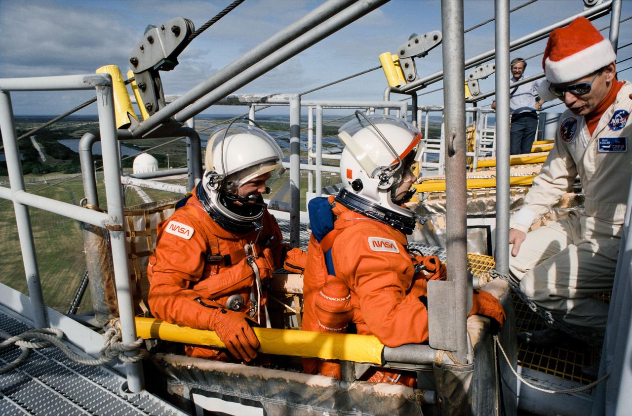
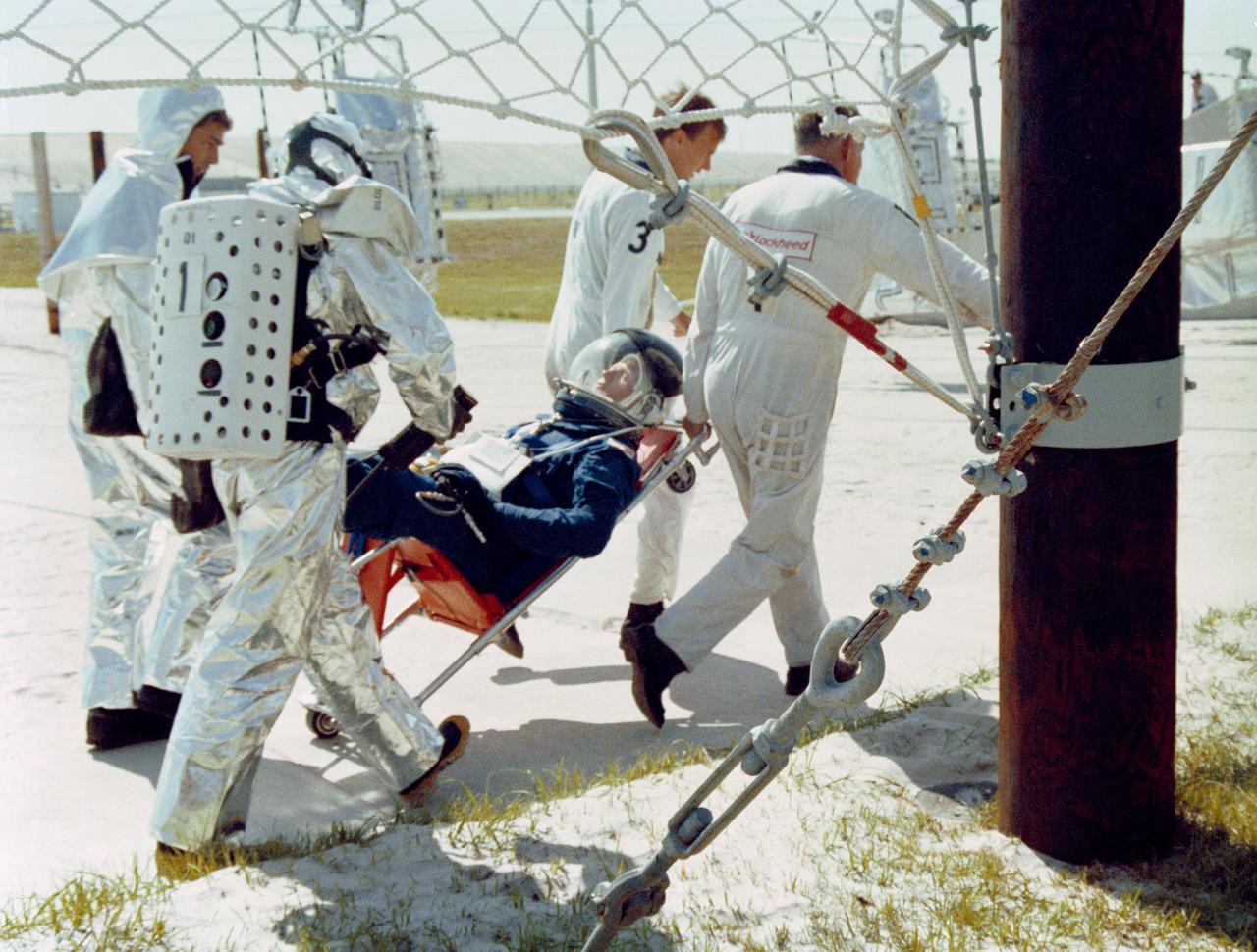
S93-25030 (15 Dec 1992) --- Two astronauts assigned to fly aboard Endeavour for the STS-54 mission are briefed on the slidewire escape system at the launch pad. Pictured in the slidewire litter are astronauts Gregory J. Harbaugh (left) and Susan J. Helms, mission specialists. They are assisted by Max Kandler of Lockheed, Houston. All five crewmembers are in Florida this week to participate in countdown demonstration tests.
A full-scale flight-test mockup of the Constellation program's Orion crew vehicle arrived at NASA's Dryden Flight Research Center in late March 2008 to undergo preparations for the first short-range flight test of the spacecraft's astronaut escape system later that year. Engineers and technicians at NASA's Langley Research Center fabricated the structure, which precisely represents the size, outer shape and mass characteristics of the Orion space capsule. The Orion crew module mockup was ferried to NASA Dryden on an Air Force C-17. After painting in the Edwards Air Force Base paint hangar, the conical capsule was taken to Dryden for installation of flight computers, instrumentation and other electronics prior to being sent to the U.S. Army's White Sands Missile Range in New Mexico for integration with the escape system and the first abort flight test in late 2008. The tests were designed to ensure a safe, reliable method of escape for astronauts in case of an emergency.
A full-scale flight-test mockup of the Constellation program's Orion crew vehicle arrived at NASA's Dryden Flight Research Center in late March 2008 to undergo preparations for the first short-range flight test of the spacecraft's astronaut escape system later that year. Engineers and technicians at NASA's Langley Research Center fabricated the structure, which precisely represents the size, outer shape and mass characteristics of the Orion space capsule. The Orion crew module mockup was ferried to NASA Dryden on an Air Force C-17. After painting in the Edwards Air Force Base paint hangar, the conical capsule was taken to Dryden for installation of flight computers, instrumentation and other electronics prior to being sent to the U.S. Army's White Sands Missile Range in New Mexico for integration with the escape system and the first abort flight test in late 2008. The tests were designed to ensure a safe, reliable method of escape for astronauts in case of an emergency.
A full-scale flight-test mockup of the Constellation program's Orion crew vehicle arrived at NASA's Dryden Flight Research Center in late March 2008 to undergo preparations for the first short-range flight test of the spacecraft's astronaut escape system later that year. Engineers and technicians at NASA's Langley Research Center fabricated the structure, which precisely represents the size, outer shape and mass characteristics of the Orion space capsule. The Orion crew module mockup was ferried to NASA Dryden on an Air Force C-17. After painting in the Edwards Air Force Base paint hangar, the conical capsule was taken to Dryden for installation of flight computers, instrumentation and other electronics prior to being sent to the U.S. Army's White Sands Missile Range in New Mexico for integration with the escape system and the first abort flight test in late 2008. The tests were designed to ensure a safe, reliable method of escape for astronauts in case of an emergency.
A full-scale flight-test mockup of the Constellation program's Orion crew vehicle arrived at NASA's Dryden Flight Research Center in late March 2008 to undergo preparations for the first short-range flight test of the spacecraft's astronaut escape system later that year. Engineers and technicians at NASA's Langley Research Center fabricated the structure, which precisely represents the size, outer shape and mass characteristics of the Orion space capsule. The Orion crew module mockup was ferried to NASA Dryden on an Air Force C-17. After painting in the Edwards Air Force Base paint hangar, the conical capsule was taken to Dryden for installation of flight computers, instrumentation and other electronics prior to being sent to the U.S. Army's White Sands Missile Range in New Mexico for integration with the escape system and the first abort flight test in late 2008. The tests were designed to ensure a safe, reliable method of escape for astronauts in case of an emergency.
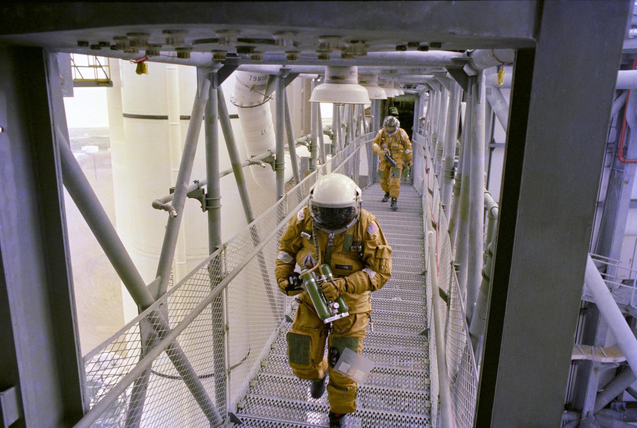
S88-40898 (4 May 1988) --- Astronauts, members of the orbiter close-out crew and fire and rescue personnel participate in a simulated emergency egress exercise near the slide wire termination point bunker at Launch Pad 39B. The simulated exercise was performed to familiarize personnel with evacuation routes as well as emergency equipment and procedures. Reasons for conducting the emergency exercises include the need to validate recent post-Challenger upgrades to the launch pad's emergency escape system and the new procedures developed in preparation for STS-26. (NOTE: The astronaut pictured and many of the others who participated in the exercises are not members of STS-26 prime crew).
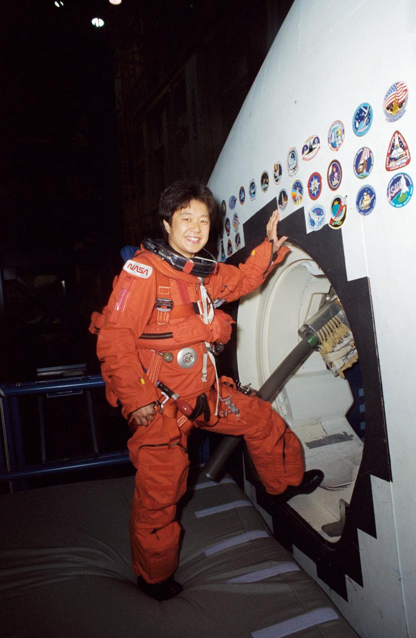
STS-65 Japanese Payload Specialist Chiaki Mukai takes a break from training at the Johnson Space Center (JSC). Wearing a training version of the orange launch and entry suit (LES), Mukai stands at the crew compartment trainer (CCT) side hatch in the Mockup and Integration Laboratory (MAIL) Bldg 9NE. Note the crew escape system (CES) pole device extending out the side hatch which would accommodate crewmembers in bailout from a troubled spacecraft. Mukai represents the National Space Development Agency (NASDA) of Japan and will serve as a payload specialist aboard Columbia, Orbiter Vehicle (OV) 102, during the STS-65 International Microgravity Laboratory 2 (IML-2) mission.
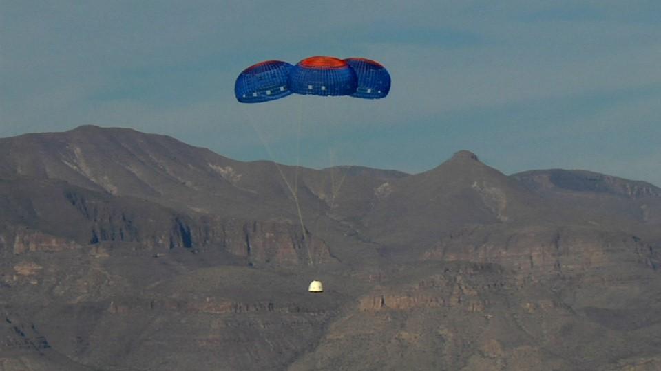
VAN HORN, Texas – Blue Origin’s New Shepard crew capsule escaped to an altitude of 2,307 feet before deploying parachutes for a safe return for a pad escape test at the company's West Texas launch site. The pusher escape system was designed and developed by Blue Origin to allow crew escape in the event of an emergency during any phase of ascent for its suborbital New Shepard system. As part of an incremental development program, the results of this test will shape the design of the escape system for the company's orbital biconic-shaped Space Vehicle. The system is expected to enable full reusability of the launch vehicle, which is different from NASA's previous launch escape systems that would pull a spacecraft away from its rocket before reaching orbit. The test was part of Blue Origin's work supporting its funded Space Act Agreement with NASA during Commercial Crew Development Round 2 CCDev2). Through initiatives like CCDev2, NASA is fostering the development of a U.S. commercial crew space transportation capability with the goal of achieving safe, reliable and cost-effective access to and from the International Space Station and low-Earth orbit. After the capability is matured and available to the government and other customers, NASA could contract to purchase commercial services to meet its station crew transportation needs. For more information, visit www.nasa.gov/commercialcrew. Image credit: Blue Origin
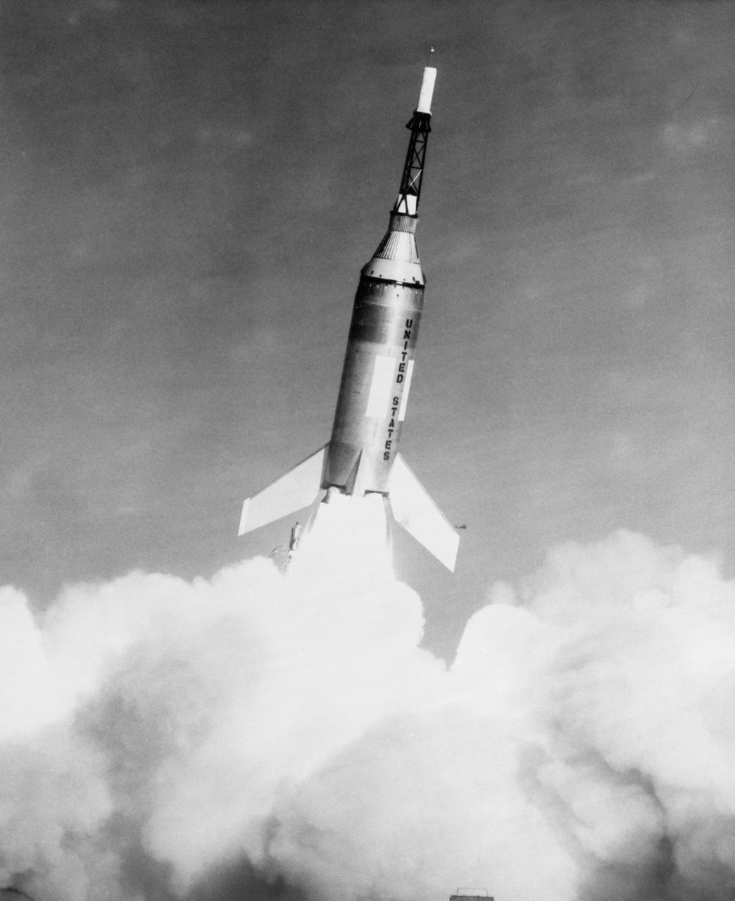
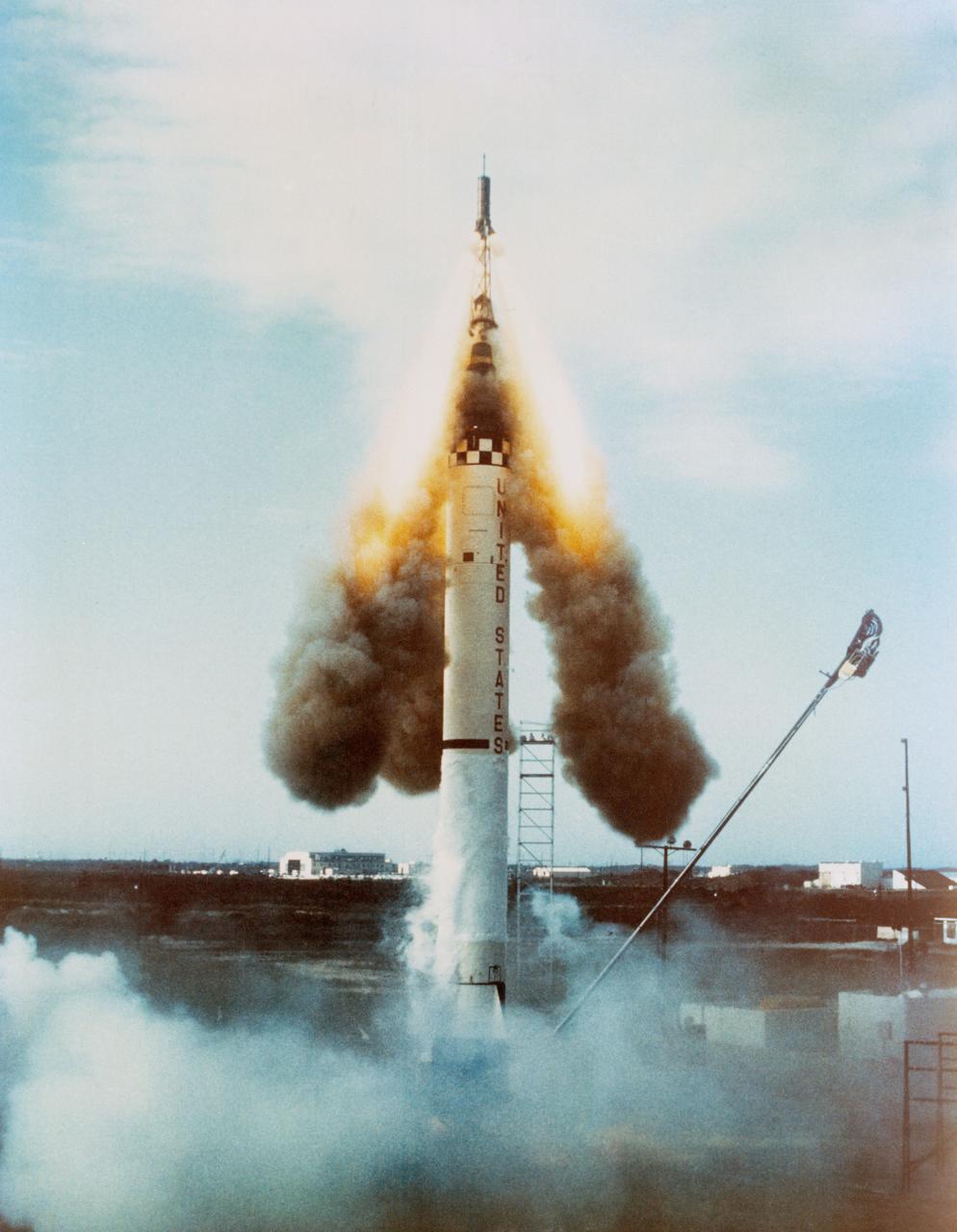
G61-00030 (4 Nov. 1959) --- Launch of Little Joe-2 from Wallops Island carrying Mercury spacecraft test article. The suborbital test flight of the Mercury capsule was to test the escape system. Vehicle functioned perfectly, but escape rocket ignited several seconds too late. Photo credit: NASA

B60-00364 (4 Nov. 1959) --- Launch of Little Joe-2 from Wallops Island carrying Mercury spacecraft test article. The suborbital test flight of the Mercury capsule was to test the escape system. Vehicle functioned perfectly, but escape rocket ignited several seconds too late. Photo credit: NASA
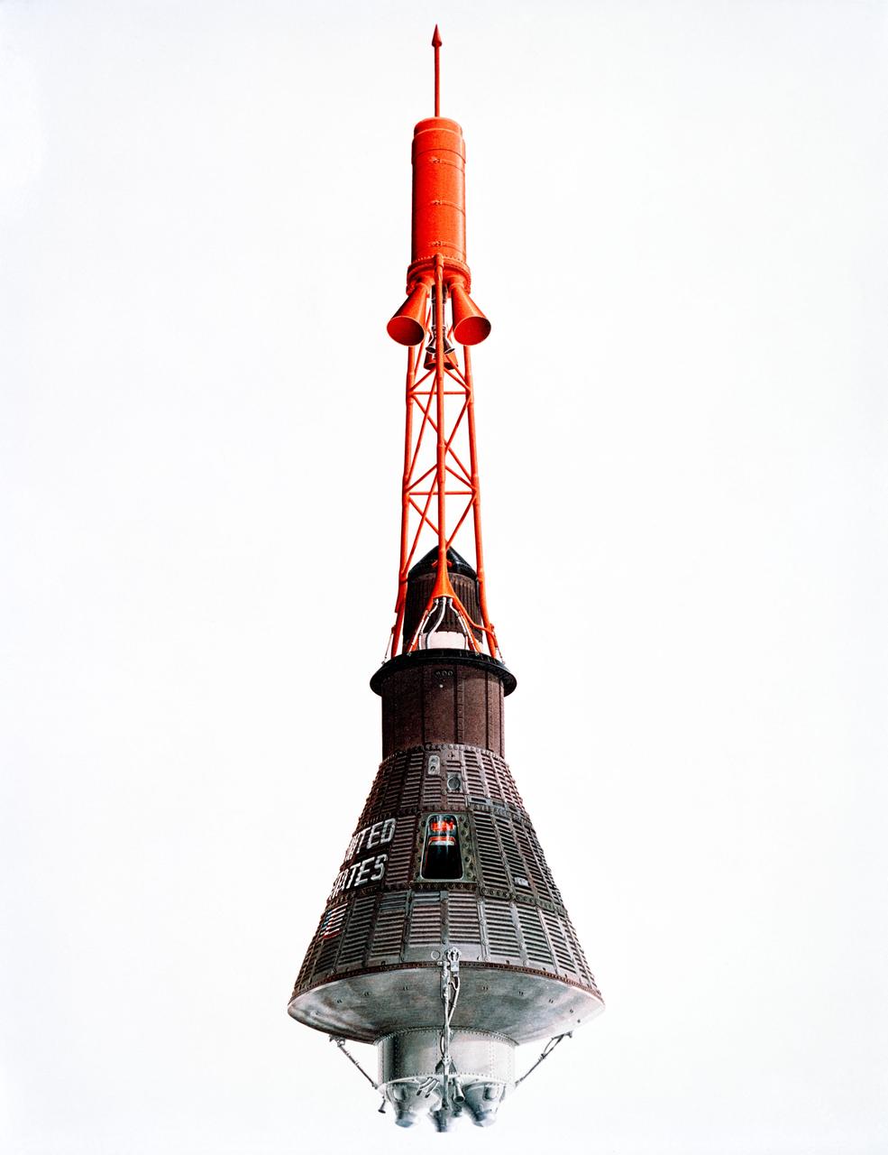
S62-04976 (31 Aug. 1962) --- Artist concept of the Mercury capsule with its launch escape system. Photo credit: NASA
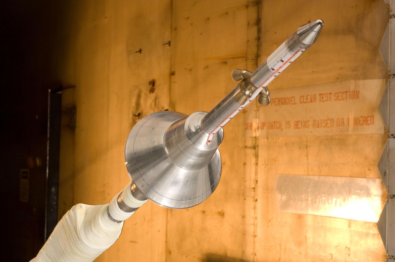
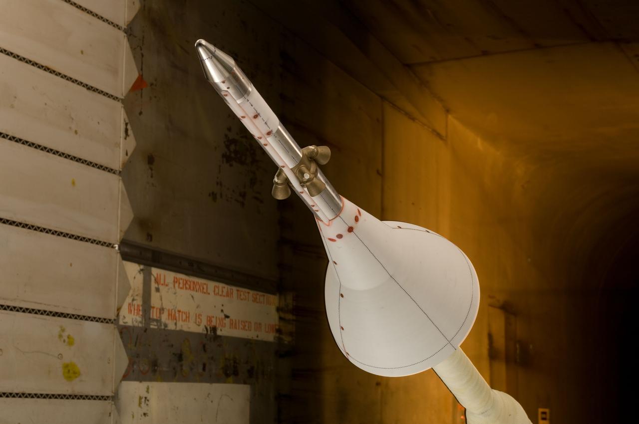
CEV (Crew Escape Vehicle) Alternative Launch Abort System (ALAS) configuration test in the Ames 11ft wind tunnel. Test-11-0172
CEV (Crew Escape Vehicle) Alternaive Launch Abort System (ALAS) configuration test in the Ames 11ft wind tunnel. Test-11-0172
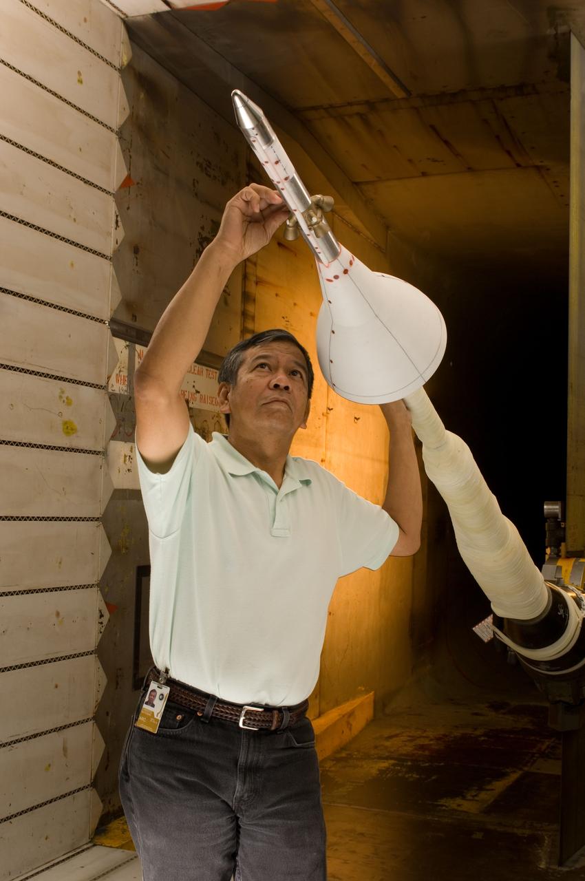
CEV (Crew Escape Vehicle) Alternative Launch Abort System (ALAS) configuration test in the Ames 11ft wind tunnel. Test-11-0172 with Paul Espinosa
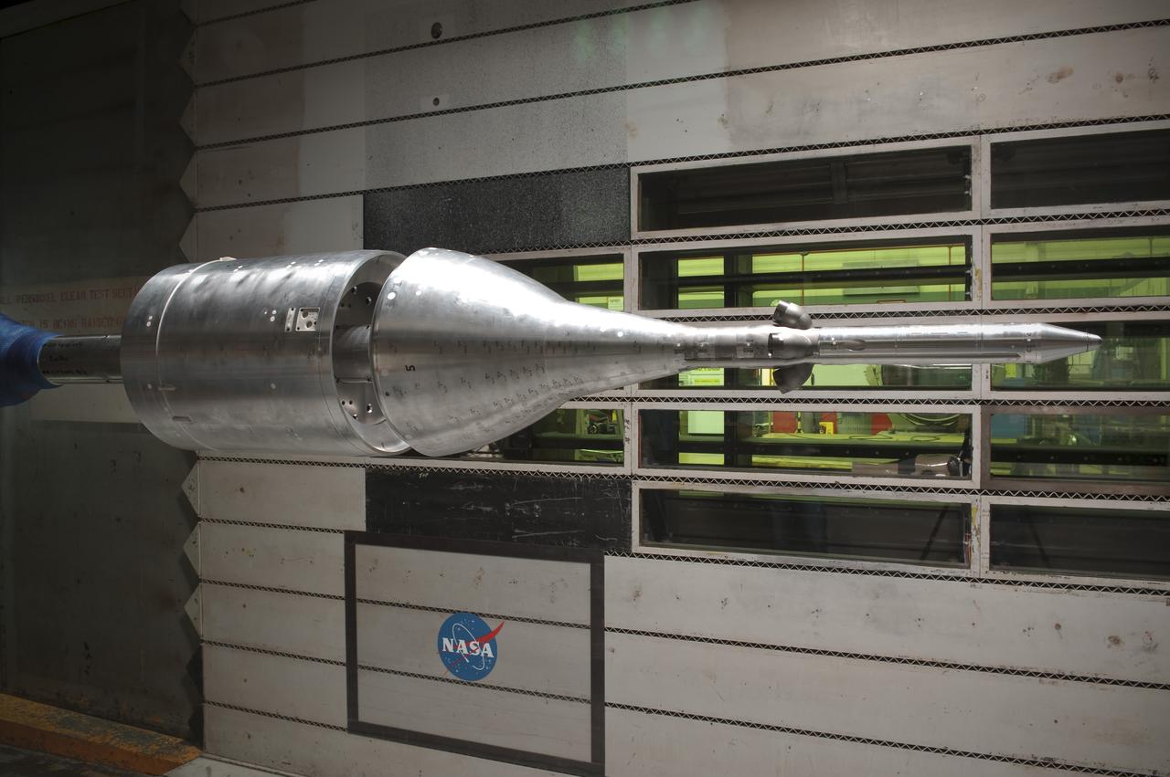
CEV/LAS (Crew Escape Vehicle - Launch Abort System) 51 aeroacoustics test-11-0185 in the Ames Research Center 11ft Transonic Wind Tunnel.
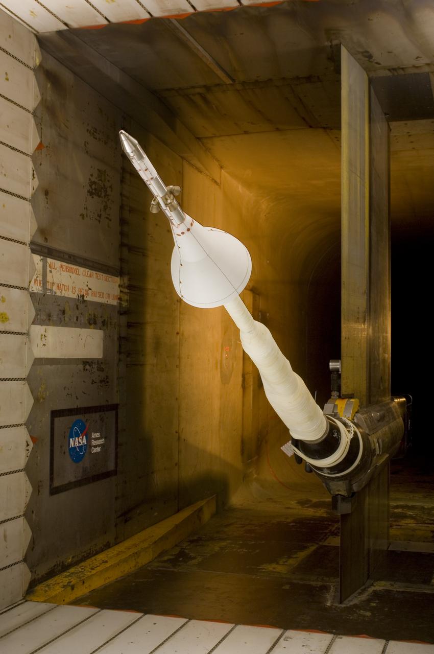
CEV (Crew Escape Vehicle) Alternative Launch Abort System (ALAS) configuration test in the Ames 11ft wind tunnel. Test-11-0172
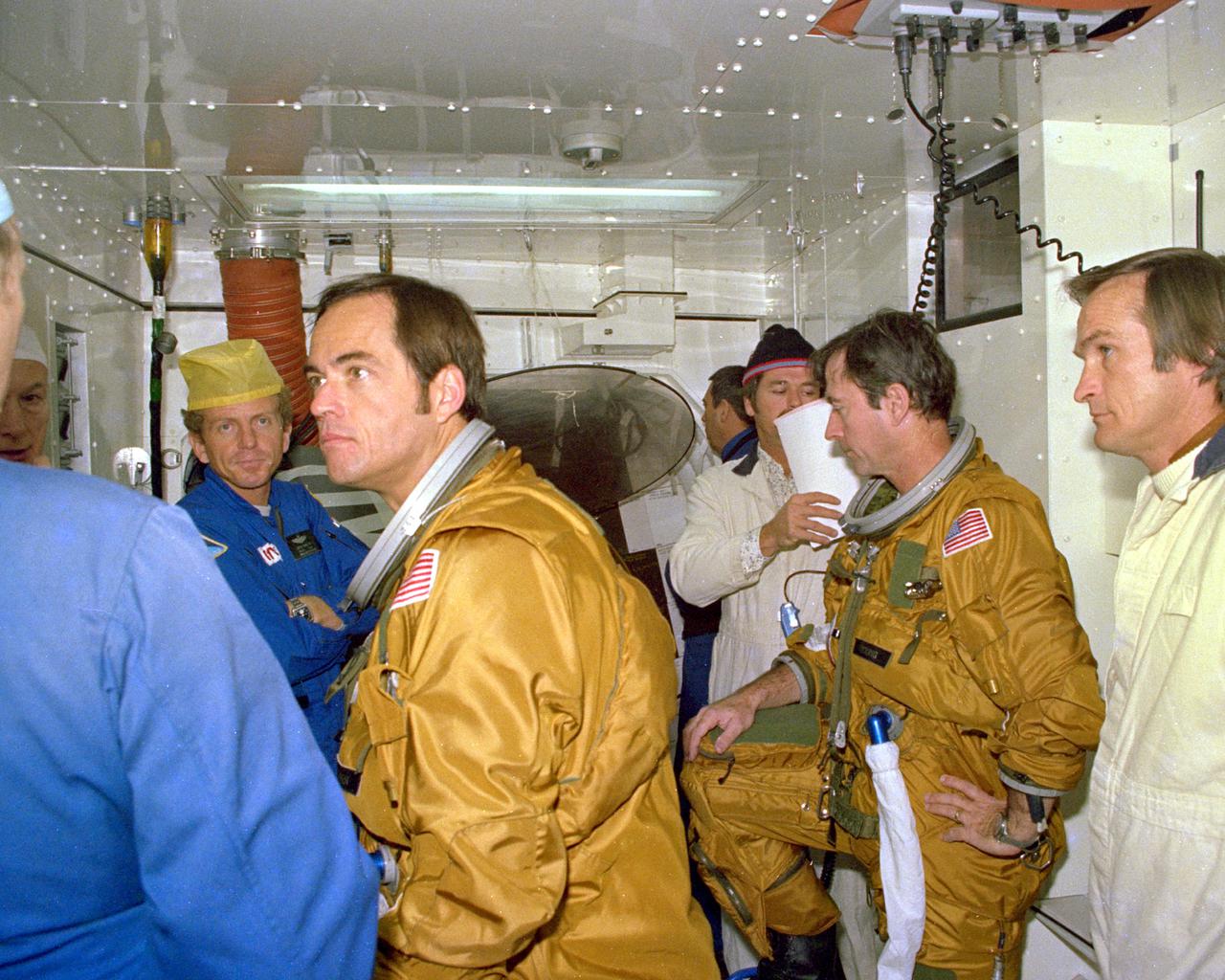
KENNEDY SPACE CENTER, FLA. - Space Shutle astronauts being briefed on the emergency pad escape system are (left to right) Loren Shriver (with hat), Prime Crew Pilot Bob Criippen and Commander John Young. The slidewire system provides a quick escape from upper launch pad platforms in case of a serious emergency. The flight crews wore the spacesuits and other equipment to be worn during a mission, but sandbags were used to duplicate the weight of riders in the slidewire baskets during the training.

KENNEDY SPACE CENTER, FLA. - Space Shuttle prime astronaut crew members Bob Crippen (left) and John Young (right) prepare for briefings on the use of the emergency pad escape system, known as the 'slidewire.' Both the prime and backup crews wore the spacesuits and other equipment they will wear during a mission. The slidewire system provides a quick and sure escape from the upper pad platforms in case of a serious emergency.
S96-18547 (30 Oct. 1996) --- Astronaut Kenneth D. Bowersox, STS-82 mission commander, chats with a crewmate (out of frame) prior to an emergency bailout training session in JSC's systems integration facility. Wearing training versions of the partial pressure launch and entry escape suit, Bowersox and his crew simulated an emergency ejection, using the escape pole system on the middeck.
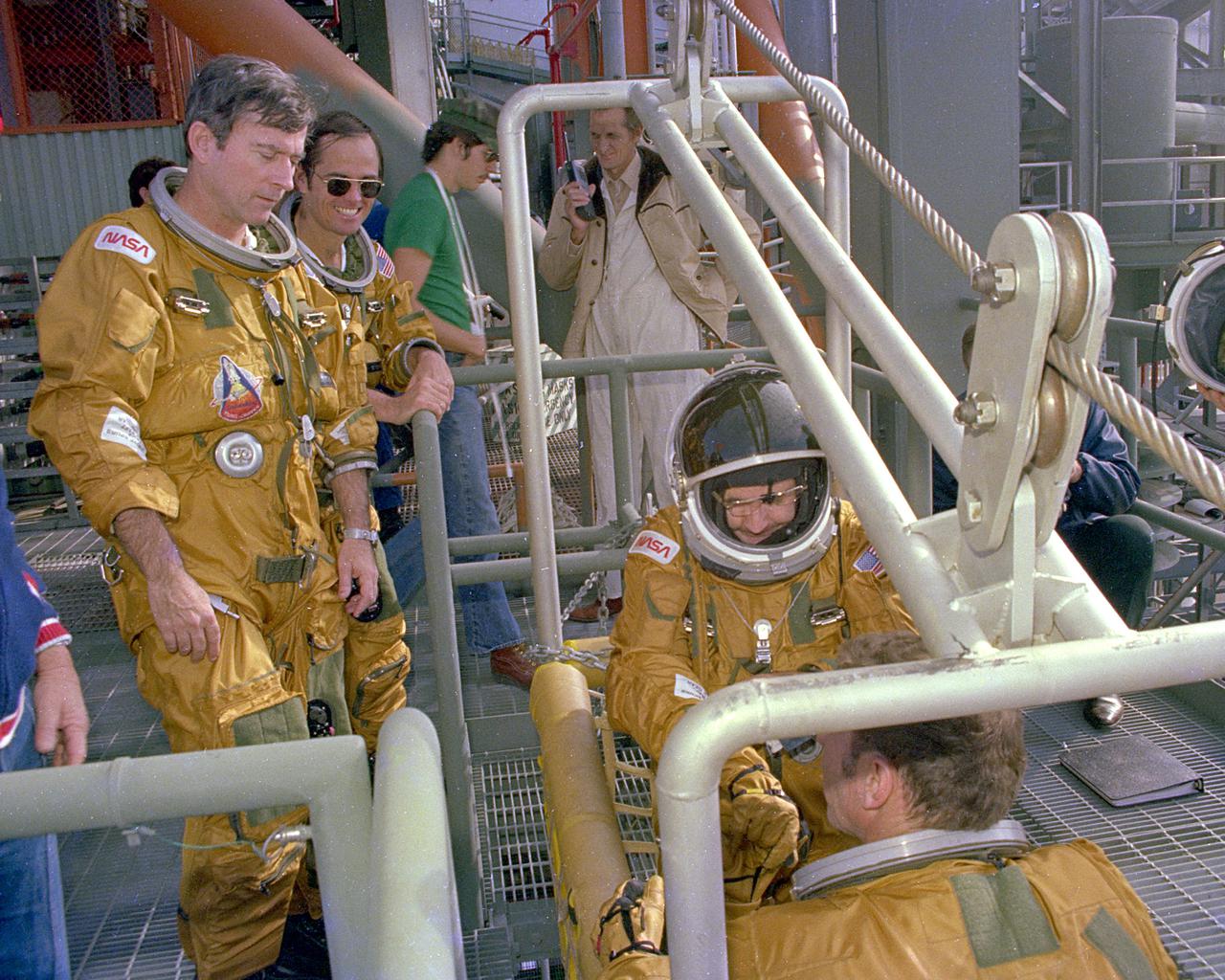
KENNEDY SPACE CENTER, FLA. - Space Shuttle prime crew Commander John Young and Pilot Bob Crippen watch as backup crew members Richard Truly and Joe Engle board the emergency pad escape system known as the slidewire. The slidewire system provides a quick escape from upper launch pad platforms in case of a serious emergency. The flight crews wore the spacesuits and other equipment to be worn during a mission, but sandbags were used to duplicate the weight of riders in the slidewire baskeets during the training.
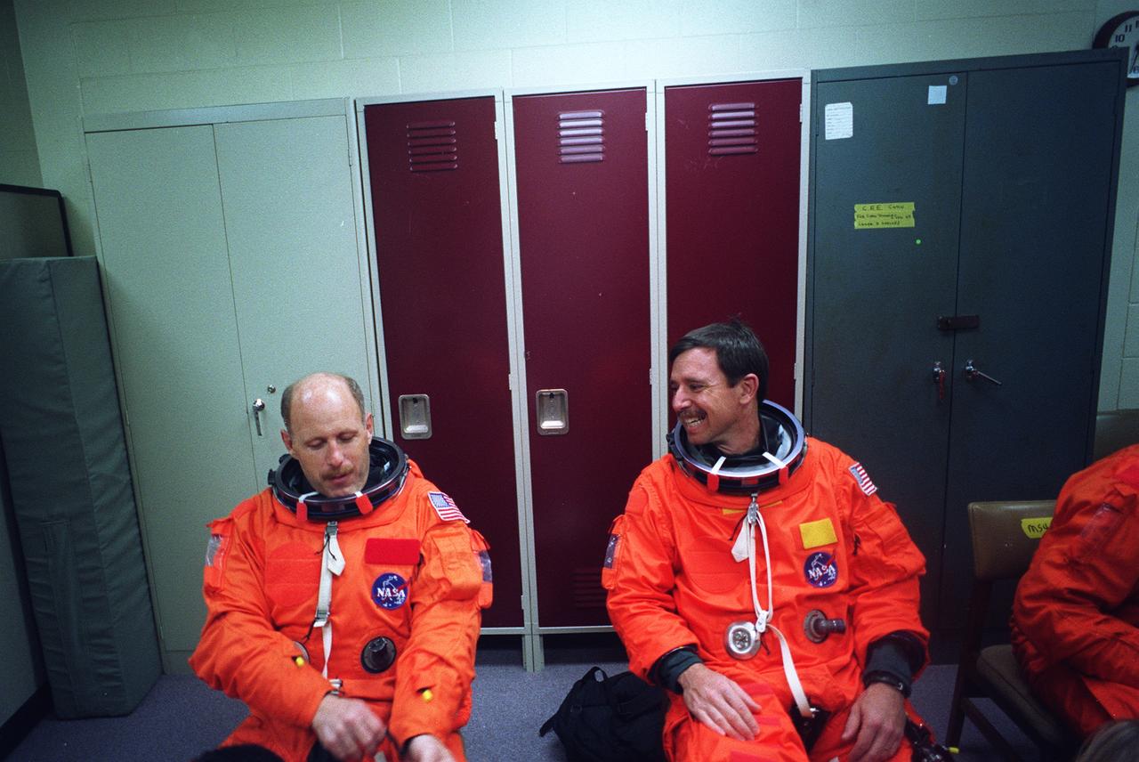
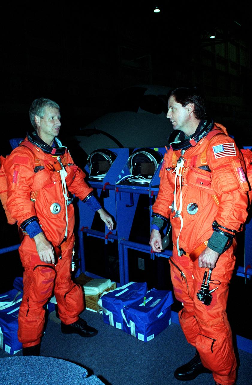
S96-18552 (30 Oct. 1996) --- Astronaut Kenneth D. Bowersox (left), STS-82 mission commander, chats with astronaut Scott J. Horowitz prior to an emergency bailout training session in JSC's systems integration facility. Wearing training versions of the partial pressure launch and entry escape suit, Bowersox and his crew simulated an emergency ejection, using the escape pole system on the mid deck, as well as other phases of their scheduled February mission.
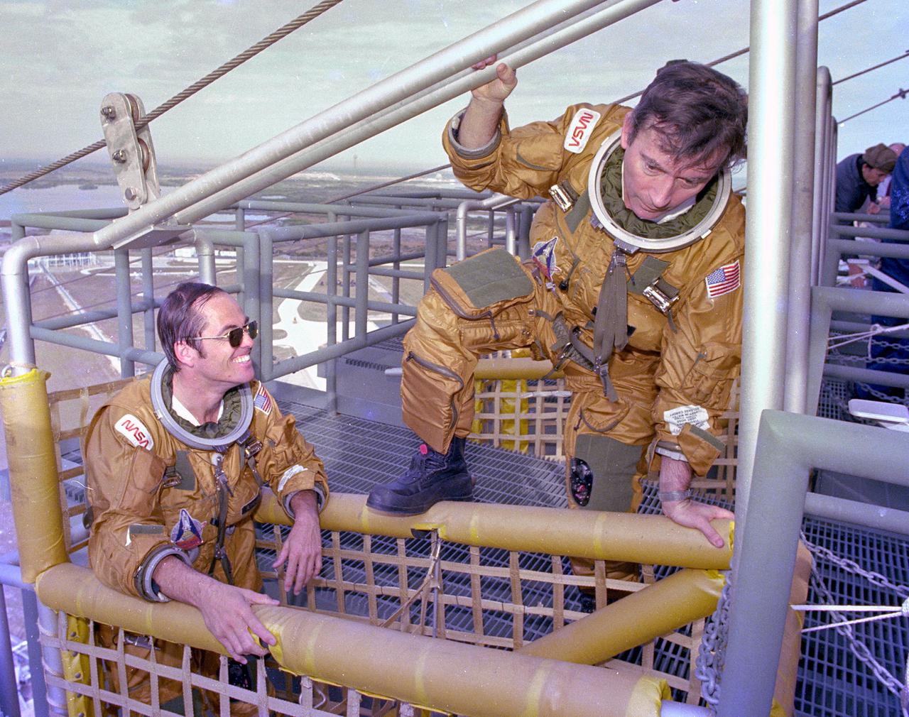
KENNEDY SPACE CENTER, FLA. - Space Shuttle prime crew astronauts Bob Crippen (left) and John Young (center) board the emergency pad escape system known as the 'slidewire.' The slidewire system provides a quick escape from upper launch pad platforms in case of a serious emergency. The flight crews wore the spacesuits and other equipment to be worn during a mission, but sandbags were used to duplicate the weight of riders in the slidewire baskets during the training.
S96-18553 (30 Oct. 1996) --- Astronaut Scott J. Horowitz, pilot, gets help with his launch and entry suit prior to a training session in JSC's systems integration facility. Wearing training versions of the partial pressure launch and entry escape suit, Horowitz and his crewmates went on to simulate an emergency ejection, using the escape pole system on the mid deck, as well as other phases of their scheduled February mission.

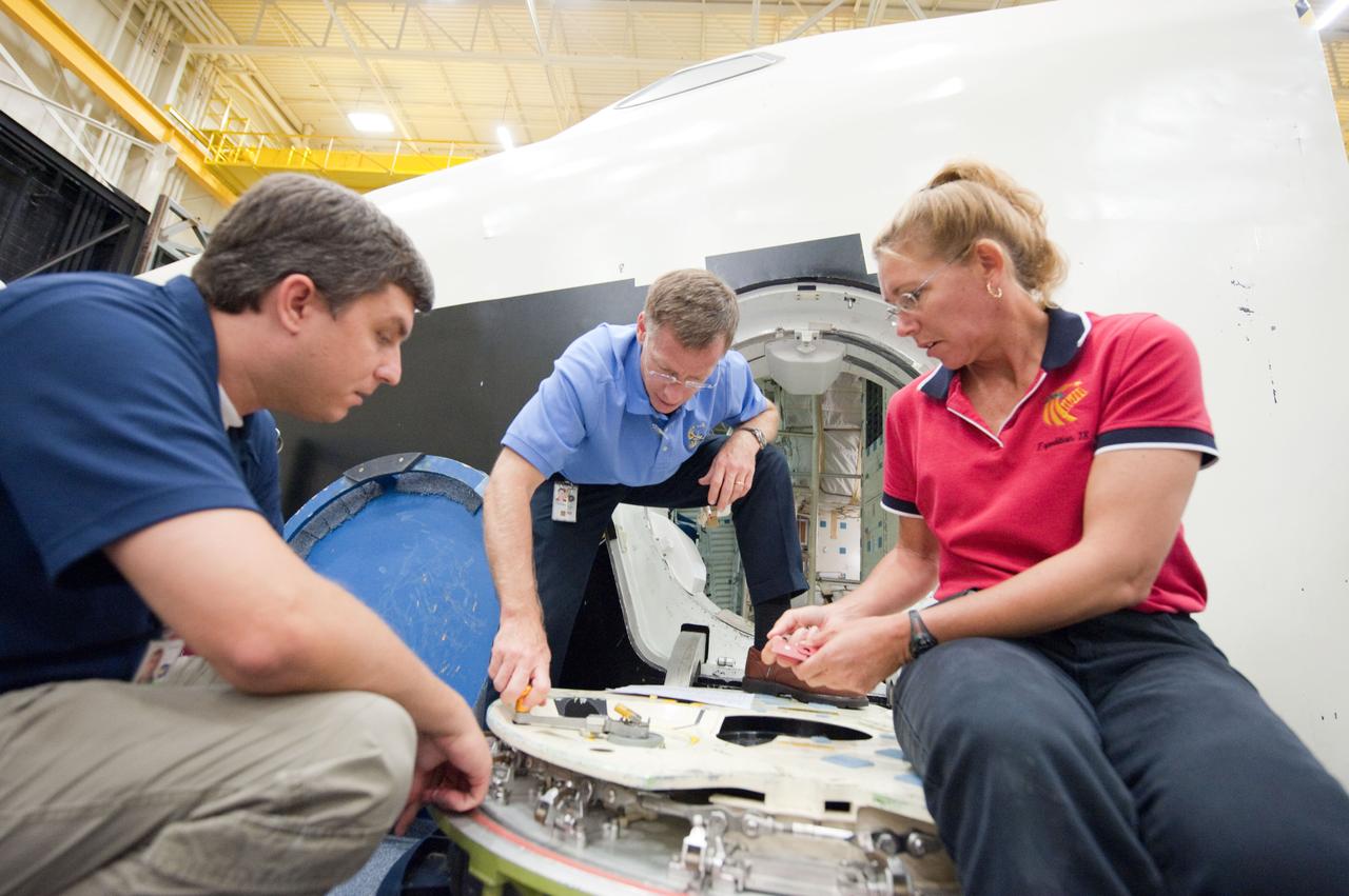
JSC2011-E-060758 (29 June 2011) --- STS-135 crew members participate in a training session in the crew compartment trainer (CCT-2) in the Space Vehicle Mock-up Facility at NASA's Johnson Space Center. Pictured are NASA astronauts Chris Ferguson (right foreground), commander; Doug Hurley (right background), pilot; Rex Walheim (center foreground) and Sandy Magnus, both mission specialists. Photo credit: NASA
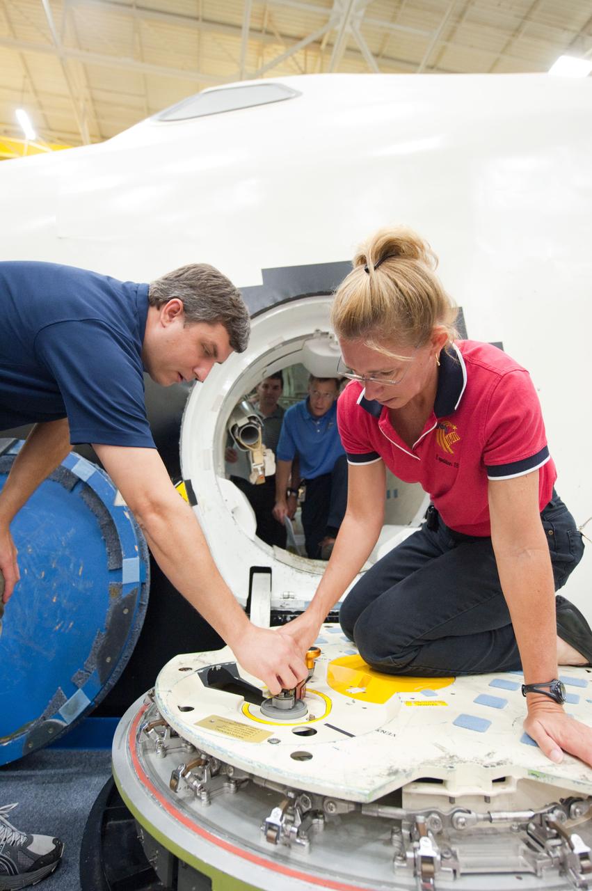
JSC2011-E-060756 (29 June 2011) --- NASA astronaut Sandy Magnus, STS-135 mission specialist, participates in a training session with the crew compartment trainer (CCT-2) in the Space Vehicle Mock-up Facility at NASA's Johnson Space Center. Here, she is briefed on the operation of the hatch. Photo credit: NASA
JSC2011-E-060757 (29 June 2011) --- NASA astronauts Chris Ferguson (center), STS-135 commander; and Sandy Magnus, mission specialist, participate in a training session with the crew compartment trainer (CCT-2) in the Space Vehicle Mock-up Facility at NASA's Johnson Space Center. The two are being briefed on the operation of the hatch. Photo credit: NASA
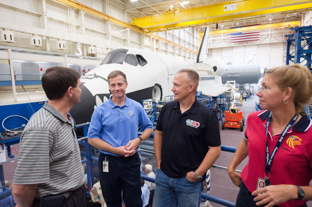
JSC2011-E-060746 (29 June 2011) --- NASA astronauts Doug Hurley (left), STS-135 pilot; Rex Walheim and Sandy Magnus, both mission specialists, are pictured during a training session in the Space Vehicle Mock-up Facility at NASA's Johnson Space Center. Photo credit: NASA
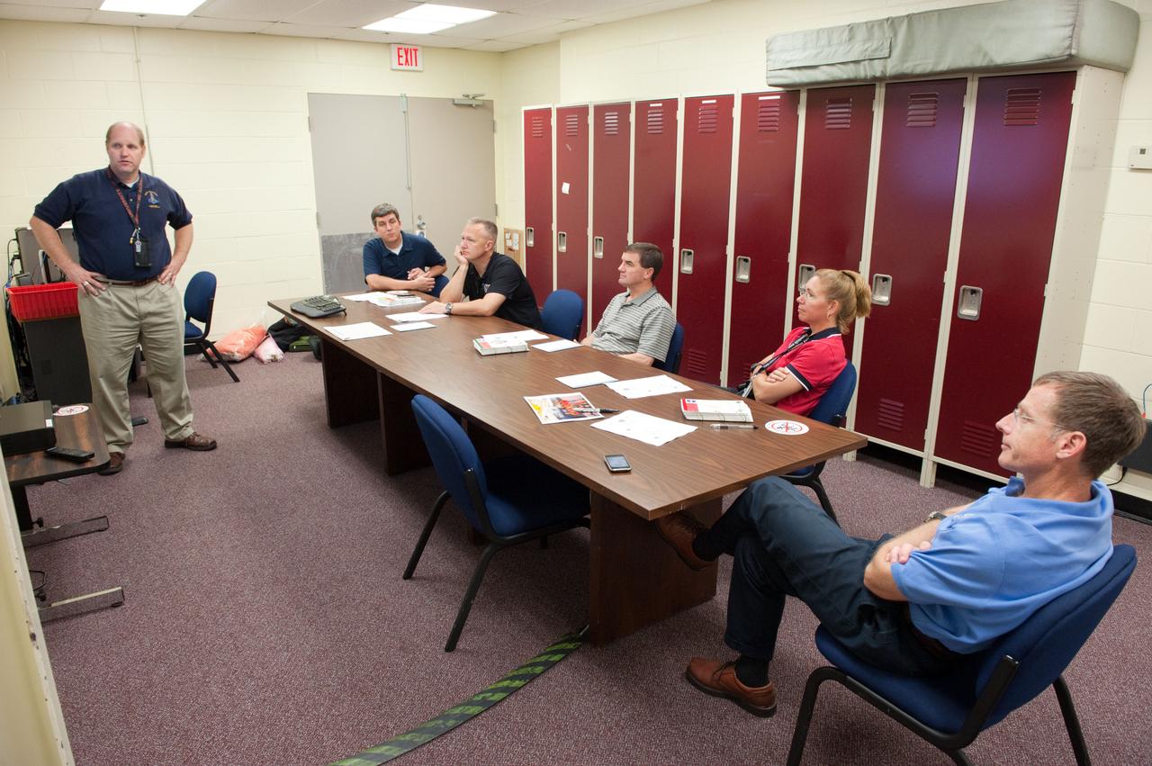
JSC2011-E-060748 (29 June 2011) --- STS-135 crew members are pictured during a training session in the Space Vehicle Mock-up Facility at NASA's Johnson Space Center. Seated from the right are NASA astronauts Chris Ferguson, commander; Sandy Magnus and Rex Walheim, both mission specialists; and Doug Hurley, pilot. Photo credit: NASA
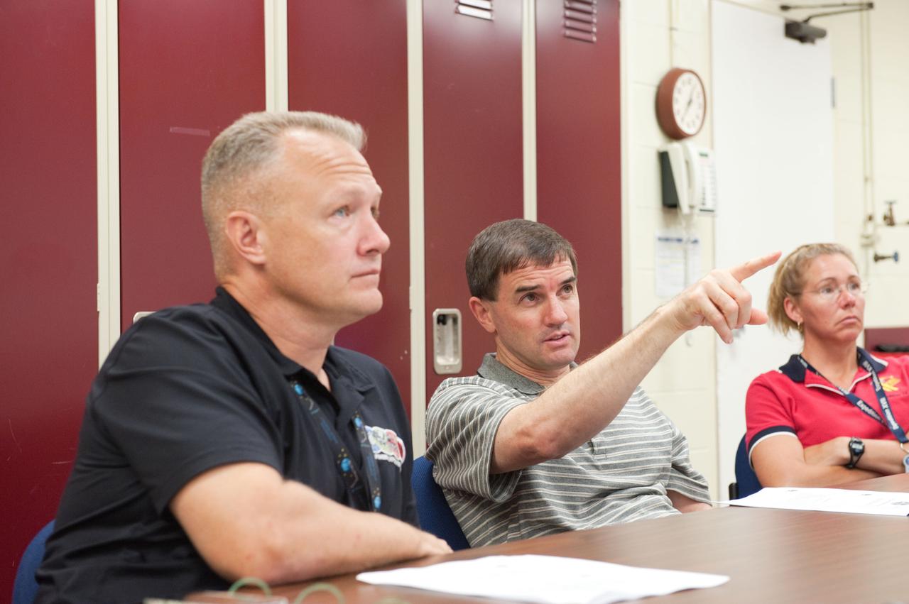
JSC2011-E-060762 (29 June 2011) --- STS-135 crew members are pictured during a training session in the Space Vehicle Mock-up Facility at NASA's Johnson Space Center. Pictured are NASA astronauts Chris Ferguson (center left), commander; Doug Hurley (center right), pilot; Rex Walheim and Sandy Magnus, both mission specialists. Photo credit: NASA
VAN HORN, Texas – Blue Origin’s pusher escape system rockets its New Shepard crew capsule away from a simulated propulsion module launch pad at the company's West Texas launch site, demonstrating a key safety system for both suborbital and orbital flights. The pad escape test took the company's suborbital crew capsule to an altitude of 2,307 feet during the flight test before descending safely by parachute to a soft landing 1,630 feet away. The pusher escape system was designed and developed by Blue Origin to allow crew escape in the event of an emergency during any phase of ascent for its suborbital New Shepard system. As part of an incremental development program, the results of this test will shape the design of the escape system for the company's orbital biconic-shaped Space Vehicle. The system is expected to enable full reusability of the launch vehicle, which is different from NASA's previous launch escape systems that would pull a spacecraft away from its rocket before reaching orbit. The test was part of Blue Origin's work supporting its funded Space Act Agreement with NASA during Commercial Crew Development Round 2 CCDev2). Through initiatives like CCDev2, NASA is fostering the development of a U.S. commercial crew space transportation capability with the goal of achieving safe, reliable and cost-effective access to and from the International Space Station and low-Earth orbit. After the capability is matured and available to the government and other customers, NASA could contract to purchase commercial services to meet its station crew transportation needs. For more information, visit www.nasa.gov/commercialcrew. Image credit: Blue Origin

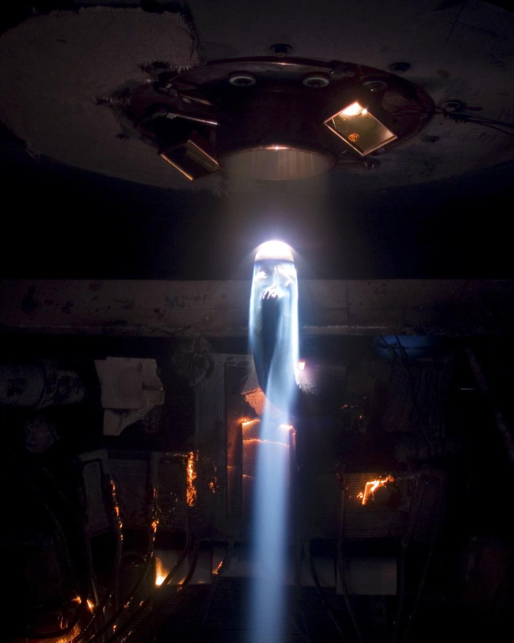
A Mercury capsule is mounted inside the Altitude Wind Tunnel for a test of its escape tower rockets at the National Aeronautics and Space Administration (NASA) Lewis Research Center. In October 1959 NASA’s Space Task Group allocated several Project Mercury assignments to Lewis. The Altitude Wind Tunnel was quickly modified so that its 51-foot diameter western leg could be used as a test chamber. The final round of tests in the Altitude Wind Tunnel sought to determine if the smoke plume from the capsule’s escape tower rockets would shroud or compromise the spacecraft. The escape tower, a 10-foot steel rig with three small rockets, was attached to the nose of the Mercury capsule. It could be used to jettison the astronaut and capsule to safety in the event of a launch vehicle malfunction on the pad or at any point prior to separation from the booster. Once actuated, the escape rockets would fire, and the capsule would be ejected away from the booster. After the capsule reached its apex of about 2,500 feet, the tower, heatshield, retropackage, and antenna would be ejected and a drogue parachute would be released. Flight tests of the escape system were performed at Wallops Island as part of the series of Little Joe launches. Although the escape rockets fired prematurely on Little Joe’s first attempt in August 1959, the January 1960 follow-up was successful.
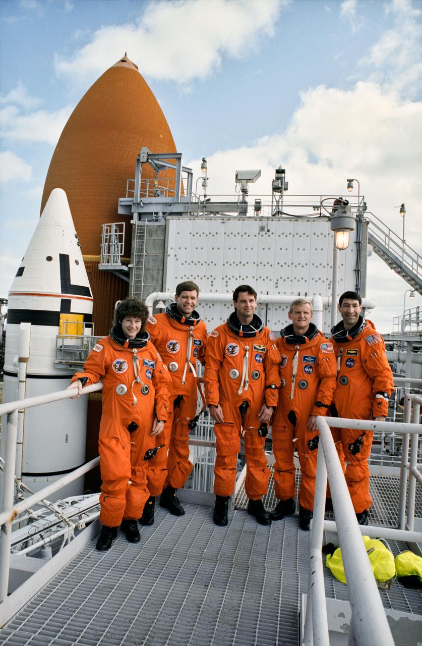
S93-25028 (15 Dec 1992) --- Astronauts assigned to fly aboard Endeavour pose near the Shuttle during a break in countdown demonstration tests. Left to right are Susan J. Helms, Donald R. McMonagle, Gregory J. Harbaugh, John H. Casper and Mario Runco Jr.
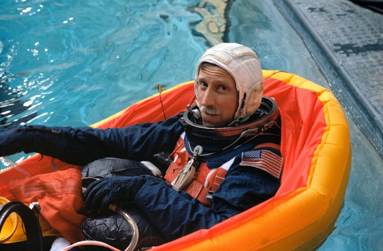
S88-42425 (20 July 1988) --- STS-26 Discovery, Orbiter Vehicle (OV) 103, Pilot Richard O. Covey, wearing the newly designed launch and entry suit (LES), floats in single-occupant life raft in JSC Weightless Environment Training Facility (WETF) Bldg 29 pool. The simulation of the escape and rescue operations utilized the crew escape system (CES) pole method of egress from the Space Shuttle.
S96-18557 (30 Oct. 1996) --- Astronauts Steven A. Hawley (left) and Gregory J. Harbaugh participate in a training session in JSC's systems integration facility. Wearing training versions of the partial pressure launch and entry escape suit, the two STS-82 mission specialists and their crewmates simulated an emergency ejection, using an escape pole on the mid deck, as well as other phases of their scheduled February mission.
S96-18556 (30 Oct. 1996) --- Astronauts Scott J. Horowitz (standing) and Kenneth D. Bowersox wind up suit donning for a training session in JSC's systems integration facility. Wearing training versions of the partial pressure launch and entry escape suit, the STS-82 pilot and mission commander joined their crewmates in simulating an emergency ejection, using an escape pole on the mid deck, as well as other phases of their scheduled February mission.
VAN HORN, Texas – Blue Origin’s New Shepard crew capsule touched down 1,630 feet from the its simulated propulsion module launch pad at the company's West Texas launch site, completing a successful test of its New Shepard crew capsule escape system. The pusher escape system was designed and developed by Blue Origin to allow crew escape in the event of an emergency during any phase of ascent for its suborbital New Shepard system. As part of an incremental development program, the results of this test will shape the design of the escape system for the company's orbital biconic-shaped Space Vehicle. The system is expected to enable full reusability of the launch vehicle, which is different from NASA's previous launch escape systems that would pull a spacecraft away from its rocket before reaching orbit. The test was part of Blue Origin's work supporting its funded Space Act Agreement with NASA during Commercial Crew Development Round 2 CCDev2). Through initiatives like CCDev2, NASA is fostering the development of a U.S. commercial crew space transportation capability with the goal of achieving safe, reliable and cost-effective access to and from the International Space Station and low-Earth orbit. After the capability is matured and available to the government and other customers, NASA could contract to purchase commercial services to meet its station crew transportation needs. For more information, visit www.nasa.gov/commercialcrew. Image credit: Blue Origin
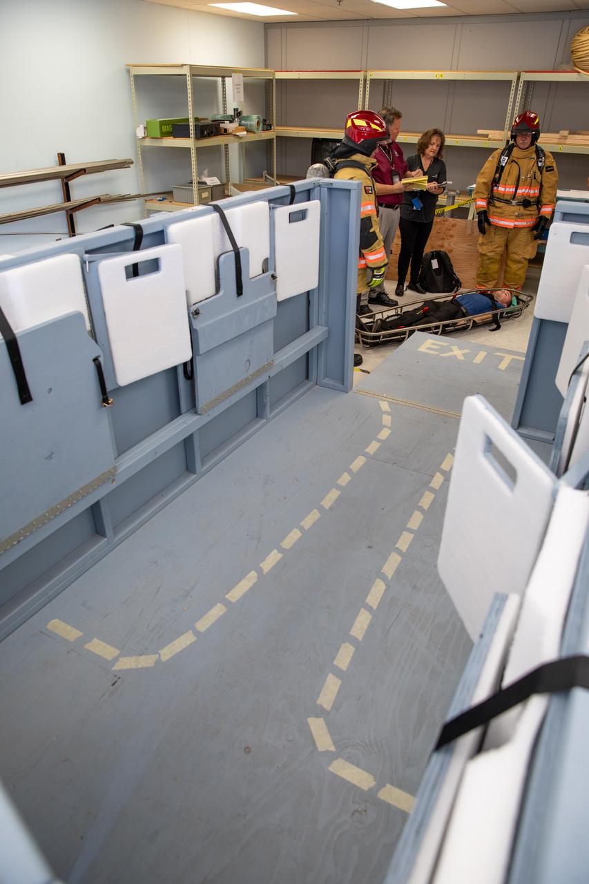
NASA Kennedy Space Center’s prime contractor Reynolds, Smith and Hill presents a mock-up of a launch pad escape basket to NASA, Kennedy Fire Rescue personnel and other stakeholders on Feb. 19, 2020. The basket would be utilized at the Florida spaceport’s Launch Pad 39B in the unlikely event of an emergency at the pad requiring evacuation during crewed missions under the Artemis Program. The actual egress basket will be designed larger than ones used during the shuttle era in order to accommodate fire rescue crew, astronauts and closeout crew. During the presentation, a fire rescue team walked through a series of trial scenarios and addressed items such as basket release location, seat depth to accommodate firefighters in full gear, sequence of loading and more.
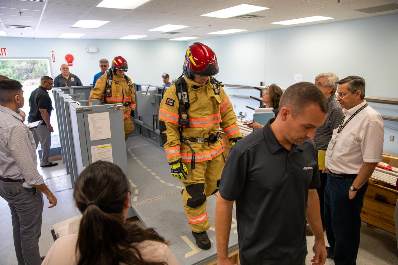
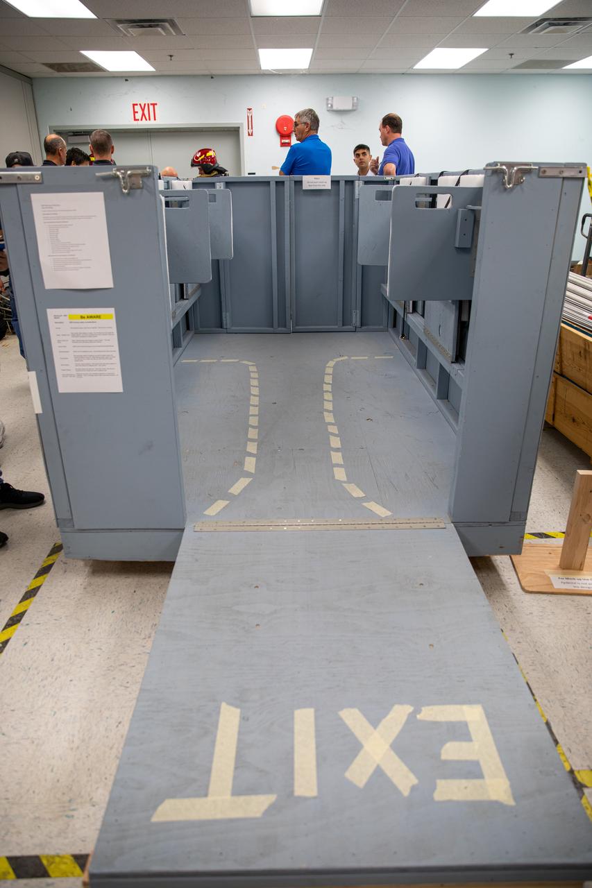
Members of NASA Kennedy Space Center’s Fire Rescue team walk through a mock-up of a launch pad escape basket on Feb. 19, 2020. Kennedy’s prime contractor Reynolds, Smith and Hill presented the mock-up to NASA, fire rescue personnel and other stakeholders at the Florida spaceport. The basket would be utilized at Launch Pad 39B in the unlikely event of an emergency at the pad requiring evacuation during crewed missions under the Artemis Program. The actual egress basket will be designed larger than ones used during the shuttle era in order to accommodate fire rescue crew, astronauts and closeout crew. During the presentation, a fire rescue team conducted a series of trial scenarios and addressed items such as basket release location, seat depth to accommodate firefighters in full gear, sequence of loading and more.
NASA Kennedy Space Center’s prime contractor Reynolds, Smith and Hill presents a mock-up of a launch pad escape basket to NASA, Kennedy Fire Rescue personnel and other stakeholders on Feb. 19, 2020. The basket would be utilized at the Florida spaceport’s Launch Pad 39B in the unlikely event of an emergency at the pad requiring evacuation during crewed missions under the Artemis Program. The actual egress basket will be designed larger than ones used during the shuttle era in order to accommodate fire rescue crew, astronauts and closeout crew. During the presentation, a fire rescue team walked through a series of trial scenarios and addressed items such as basket release location, seat depth to accommodate firefighters in full gear, sequence of loading and more.
NASA Kennedy Space Center’s prime contractor Reynolds, Smith and Hill presents a mock-up of a launch pad escape basket to NASA, Kennedy Fire Rescue personnel and other stakeholders on Feb. 19, 2020. The basket would be utilized at the Florida spaceport’s Launch Pad 39B in the unlikely event of an emergency at the pad requiring evacuation during crewed missions under the Artemis Program. The actual egress basket will be designed larger than ones used during the shuttle era in order to accommodate fire rescue crew, astronauts and closeout crew. During the presentation, a fire rescue team walked through a series of trial scenarios and addressed items such as basket release location, seat depth to accommodate firefighters in full gear, sequence of loading and more.
On Feb. 19, 2020, at NASA’s Kennedy Space Center in Florida, prime contractor Reynolds, Smith and Hill presents a mock-up of a launch pad escape basket to NASA, Kennedy Fire Rescue personnel and other stakeholders. The basket would be utilized at Launch Pad 39B in the unlikely event of an emergency at the pad requiring evacuation during crewed missions under the Artemis Program. The actual egress basket will be designed larger than ones used during the shuttle era in order to accommodate fire rescue crew, astronauts and closeout crew. During the presentation, a fire rescue team walked through a series of trial scenarios and addressed items such as basket release location, seat depth to accommodate firefighters in full gear, sequence of loading and more.
KENNEDY SPACE CENTER, FLA. - On the Fixed Service Structure on Launch Complex 39A, space shuttle prime and backup astronaut crews plus other astronauts and ground personnel are given training on the use of the emergency pad escape system known as the “slidewire”. The slidewire system provides a quick escape from upper launch pad platforms in case of a serious emergency. The flight crews wear the spacesuits and other equipment to be worn during a mission, but sandbags are used to duplicate the weight of riders in the slidewire baskets during the training. The STS-1 mission, known as a shuttle systems test flight, will seek to demonstrate safe launch into orbit and safe return of the orbiter and crew and verify the combined performance of the entire shuttle vehicle -- orbiter, solid rocket boosters and external tank. STS-1 will be launched from Pad A at the Kennedy Space Center's Launch Complex 39 no earlier than March 1981.
The Little Joe launch vehicle for the LJ1 mission on the launch pad at the wallops Flight Facility, Wallops Island, Virginia, on January 21, 1960. This mission achieved the suborbital Mercury cupsule test, testing of the escape system, and biomedical tests by using a monkey, named Miss Sam.
S63-00193 (29 July 1960) --- Launch of the unmanned Mercury-Atlas 1 (MA-1) from Cape Canaveral, Florida. Premature engine cutoff at launch terminated the test. Emergency escape system jettisoned. The Altas exploded 65 seconds after launch. Photo credit: NASA
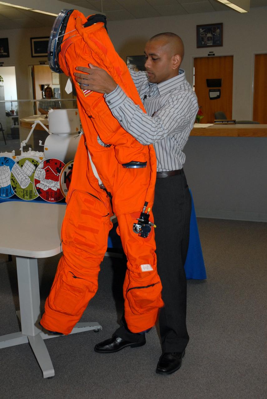
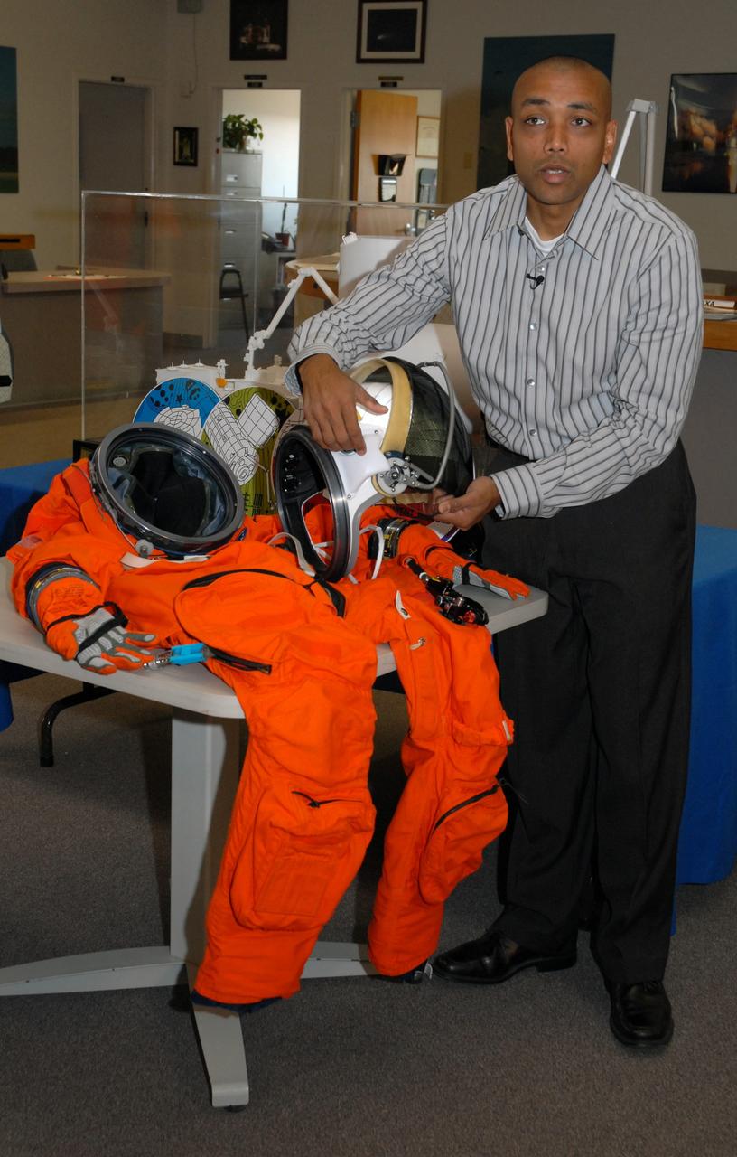
CAPE CANAVERAL, Fla. -- In the NASA News Center at NASA's Kennedy Space Center, Shuttle Crew Escape System Manager KC Chhipwadia demonstrates the launch and entry suit used by shuttle crews during their missions. He explains that entry into the suit is from the back. Photo credit: NASA/Amanda Diller
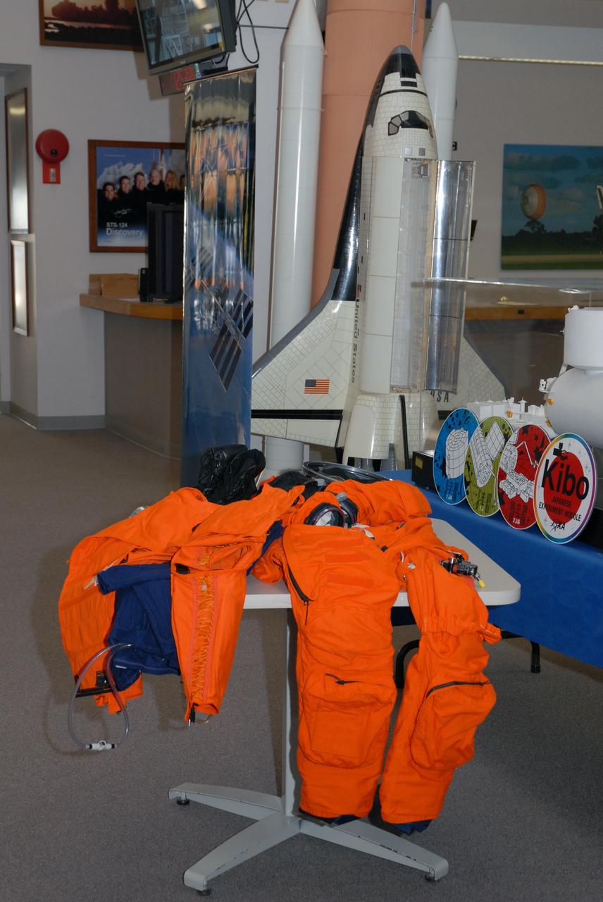
CAPE CANAVERAL, Fla. -- In the NASA News Center at NASA's Kennedy Space Center, components of the astronauts' launch and entry suit are on display for the media. Shuttle Crew Escape System Manager KC Chhipwadia described the individual pieces and their importance to the safety of the shuttle crews during their missions. Photo credit: NASA/Amanda Diller

The launch of the Little Joe booster for the LJ1B mission on the launch pad from the wallops Flight Facility, Wallops Island, Virginia, on January 21, 1960. This mission achieved the suborbital Mercury capsule test, testing of the escape system, and biomedical tests by using a monkey, named Miss Sam.
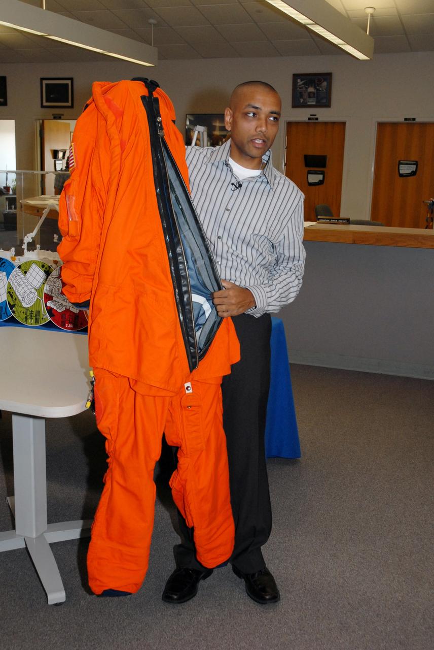
CAPE CANAVERAL, Fla. -- In the NASA News Center at NASA's Kennedy Space Center, Shuttle Crew Escape System Manager KC Chhipwadia demonstrates the launch and entry suit used by shuttle crews during their missions. He explains that entry into the suit is from the back. Photo credit: NASA/Amanda Diller
JSC2000-05553 (3 August 2000) --- Astronaut Paul W. Richards, STS-102 mission specialist, during a session of egress training in the Johnson Space Center's Systems Integration Facility, uses a Sky-genie device to escape from a simulated shuttle in trouble. The full fuselage trainer (FFT) is a full scale mockup of a shuttle.

This photograph shows the installation of a Mercury capsule and escape system on top of a booster prior to test firing of the Mercury-Redstone at Marshall Space Flight Center's (MSFC's) Redstone Test Stand. Assembled by MSFC, the Mercury-Redstone was designed to place a marned space capsule in orbital flight around the Earth and recover both safely.
CEV TPS Advanced Develpment Project IHF-171 testing TSF photos (Crew Escape Vehicle Thermal Protection System) cleared for release by NASA Ames Thermo-Physics Facilities Branch - Image used for cover of Aerospace America magazine April 2007 issue
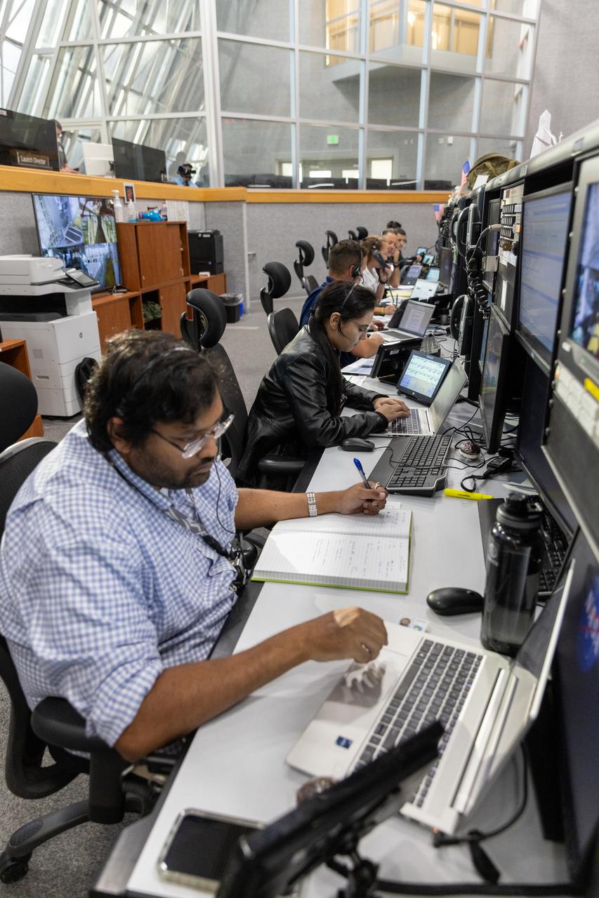
Members of the Artemis II launch team, including personnel with NASA’s Exploration Ground Systems participate in an emergency escape or egress demonstration simulation for the Artemis II mission inside Firing Room 1 in the Launch Control Center at NASA’s Kennedy on Monday, Aug. 12, 2024. Other members of the closeout crew, pad rescue team, and the Exploration Ground Systems Program performed emergency egress demonstrations during a series of integrated system verification tests at Launch Pad 39B in preparation for the Artemis II launch.
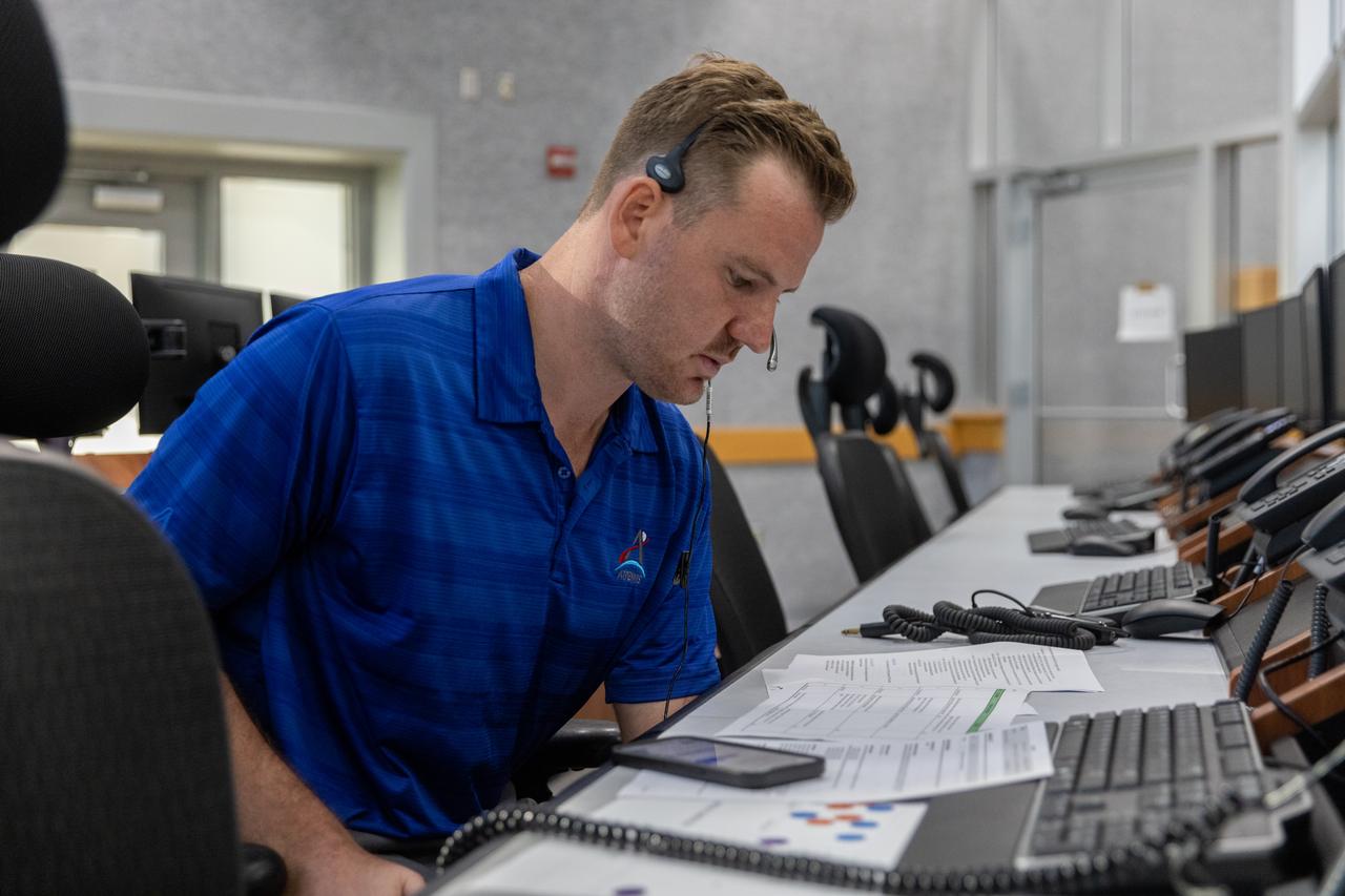
Joseph Pavicic, operations project engineer, Exploration Ground Systems at NASA’s Kennedy Space Center in Florida, participates in an emergency escape or egress demonstration simulation for the Artemis II mission inside Firing Room 1 in the Launch Control Center at NASA’s Kennedy on Monday, Aug. 12, 2024. Other members of the closeout crew, pad rescue team, and the Exploration Ground Systems Program performed emergency egress demonstrations during a series of integrated system verification tests at Launch Pad 39B in preparation for the Artemis II launch.
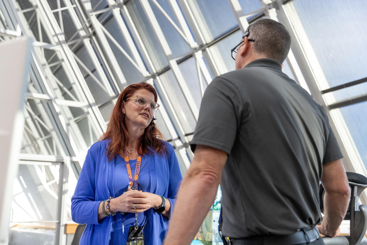
Charlie Blackwell-Thompson, Artemis launch director, Exploration Ground Systems at NASA’s Kennedy Space Center in Florida, participates in an emergency escape or egress demonstration simulation for the Artemis II mission inside Firing Room 1 in the Launch Control Center at NASA’s Kennedy on Monday, Aug. 12, 2024. Other members of the closeout crew, pad rescue team, and the Exploration Ground Systems Program performed emergency egress demonstrations during a series of integrated system verification tests at Launch Pad 39B in preparation for the Artemis II launch.
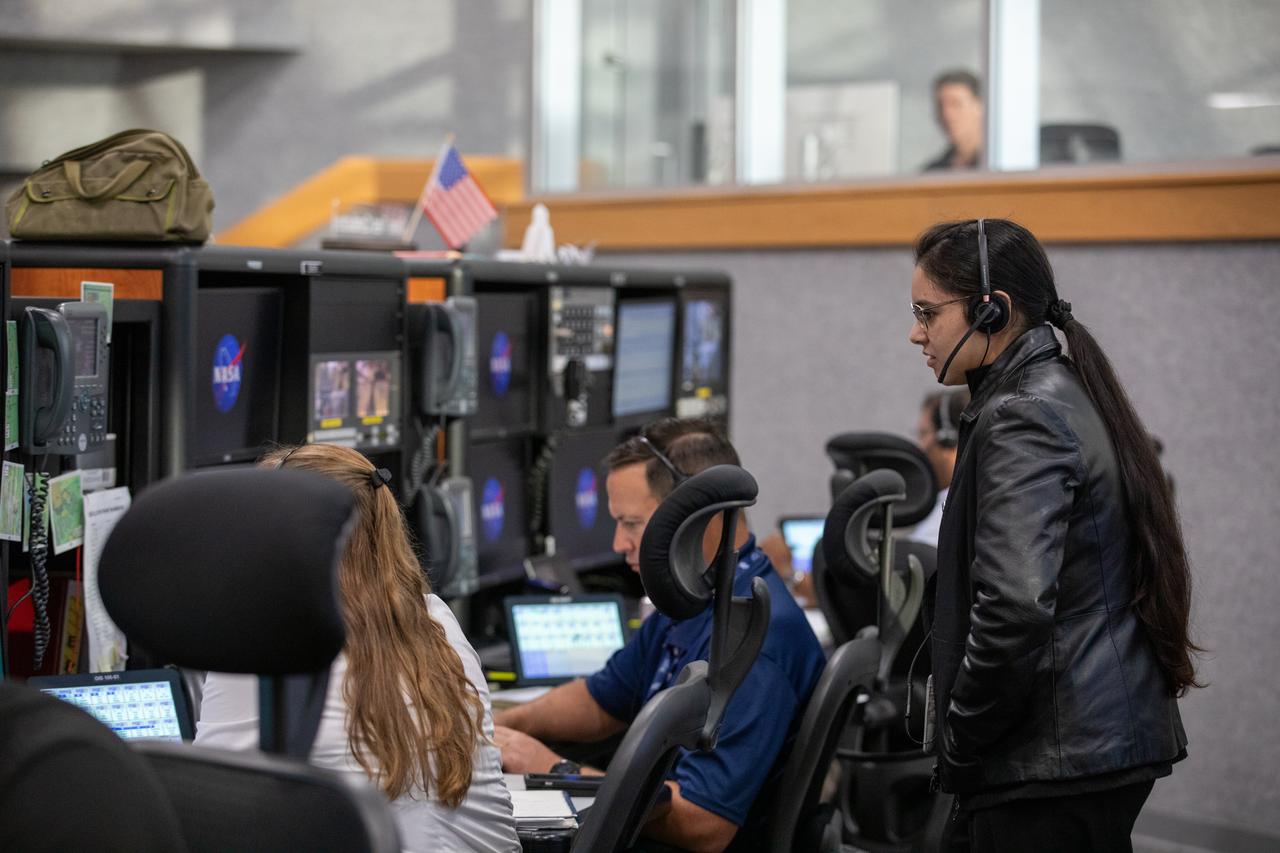
Members of the Artemis II launch team, including personnel with NASA’s Exploration Ground Systems participate in an emergency escape or egress demonstration simulation for the Artemis II mission inside Firing Room 1 in the Launch Control Center at NASA’s Kennedy on Monday, Aug. 12, 2024. Other members of the closeout crew, pad rescue team, and the Exploration Ground Systems Program performed emergency egress demonstrations during a series of integrated system verification tests at Launch Pad 39B in preparation for the Artemis II launch.
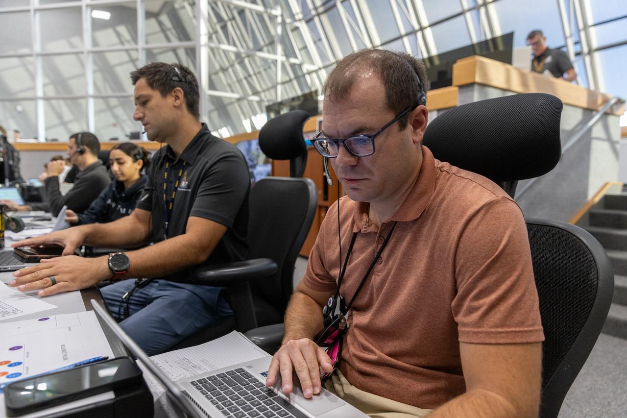
Jeremy Graeber, Artemis assistant launch director, Exploration Ground Systems at NASA’s Kennedy Space Center in Florida, participates in an emergency escape or egress demonstration simulation for the Artemis II mission inside Firing Room 1 in the Launch Control Center at NASA’s Kennedy on Monday, Aug. 12, 2024. Other members of the closeout crew, pad rescue team, and the Exploration Ground Systems Program performed emergency egress demonstrations during a series of integrated system verification tests at Launch Pad 39B in preparation for the Artemis II launch.
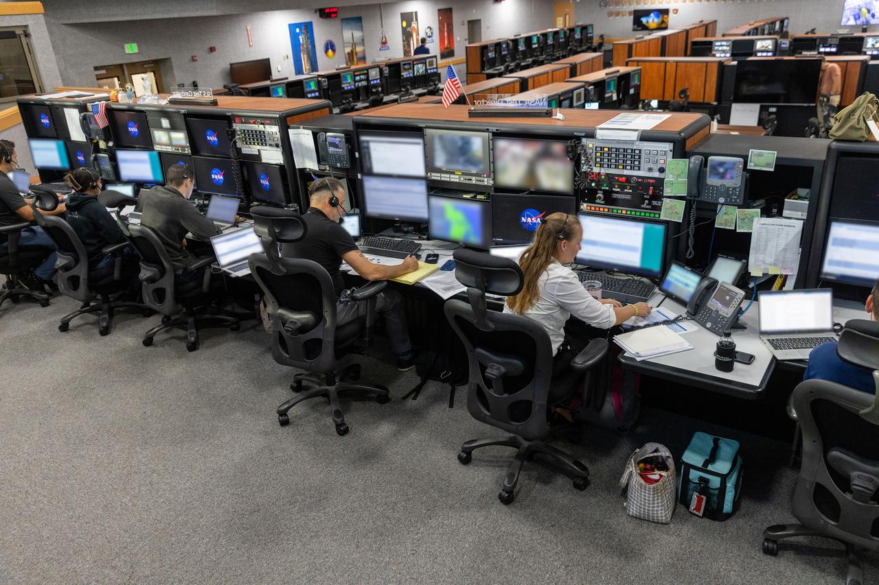
Members of the Artemis II launch team, including personnel with NASA’s Exploration Ground Systems participate in an emergency escape or egress demonstration simulation for the Artemis II mission inside Firing Room 1 in the Launch Control Center at NASA’s Kennedy on Monday, Aug. 12, 2024. Other members of the closeout crew, pad rescue team, and the Exploration Ground Systems Program performed emergency egress demonstrations during a series of integrated system verification tests at Launch Pad 39B in preparation for the Artemis II launch.
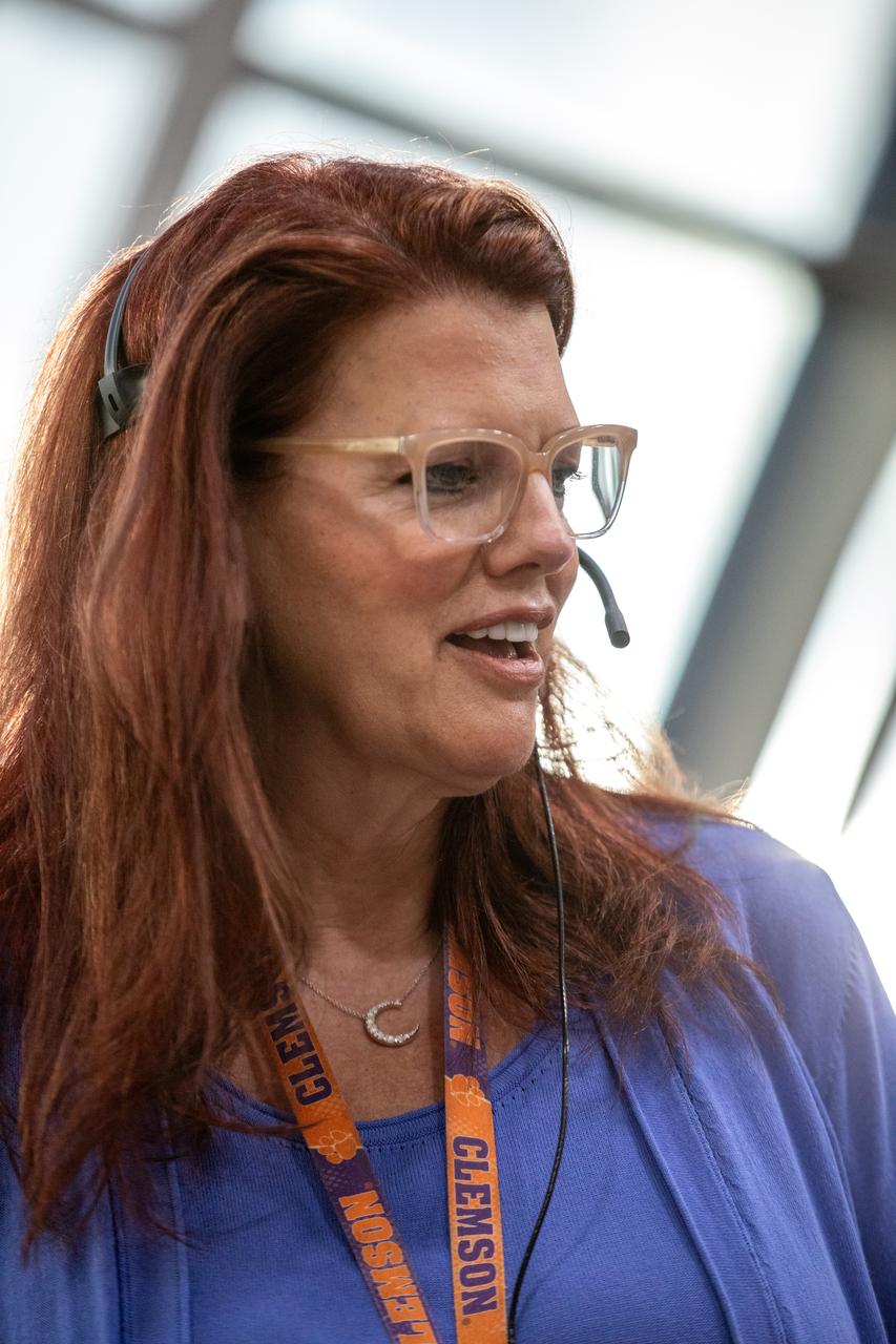
Charlie Blackwell-Thompson, Artemis launch director, Exploration Ground Systems at NASA’s Kennedy Space Center in Florida, participates in an emergency escape or egress demonstration simulation for the Artemis II mission inside Firing Room 1 in the Launch Control Center at NASA’s Kennedy on Monday, Aug. 12, 2024. Other members of the closeout crew, pad rescue team, and the Exploration Ground Systems Program performed emergency egress demonstrations during a series of integrated system verification tests at Launch Pad 39B in preparation for the Artemis II launch.

After investigating the upper atmosphere of the Red Planet for a full Martian year, NASA’s MAVEN mission has determined that the escaping water does not always go gently into space. Sophisticated measurements made by a suite of instruments on the Mars Atmosphere and Volatile Evolution, or MAVEN, spacecraft revealed the ups and downs of hydrogen escape – and therefore water loss. The escape rate peaked when Mars was at its closest point to the sun and dropped off when the planet was farthest from the sun. The rate of loss varied dramatically overall, with 10 times more hydrogen escaping at the maximum. “MAVEN is giving us unprecedented detail about hydrogen escape from the upper atmosphere of Mars, and this is crucial for helping us figure out the total amount of water lost over billions of years,” said Ali Rahmati, a MAVEN team member at the University of California at Berkeley who analyzed data from two of the spacecraft’s instruments. Hydrogen in Mars’ upper atmosphere comes from water vapor in the lower atmosphere. An atmospheric water molecule can be broken apart by sunlight, releasing the two hydrogen atoms from the oxygen atom that they had been bound to. Several processes at work in Mars’ upper atmosphere may then act on the hydrogen, leading to its escape. Read more: <a href="http://go.nasa.gov/2dAgAV4" rel="nofollow">go.nasa.gov/2dAgAV4</a> <b><a href="http://www.nasa.gov/audience/formedia/features/MP_Photo_Guidelines.html" rel="nofollow">NASA image use policy.</a></b> <b><a href="http://www.nasa.gov/centers/goddard/home/index.html" rel="nofollow">NASA Goddard Space Flight Center</a></b> enables NASA’s mission through four scientific endeavors: Earth Science, Heliophysics, Solar System Exploration, and Astrophysics. Goddard plays a leading role in NASA’s accomplishments by contributing compelling scientific knowledge to advance the Agency’s mission. <b>Follow us on <a href="http://twitter.com/NASAGoddardPix" rel="nofollow">Twitter</a></b> <b>Like us on <a href="http://www.facebook.com/pages/Greenbelt-MD/NASA-Goddard/395013845897?ref=tsd" rel="nofollow">Facebook</a></b> <b>Find us on <a href="http://instagrid.me/nasagoddard/?vm=grid" rel="nofollow">Instagram</a></b>
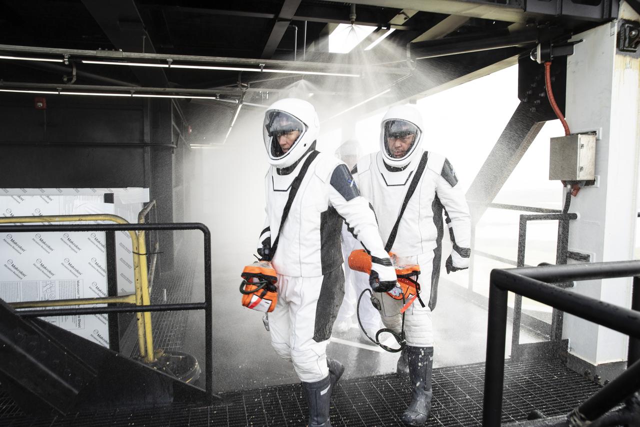
NASA and SpaceX conducted a formal verification of the company’s emergency escape system on Sept. 18, 2019, at Kennedy Space Center’s Launch Complex 39A in Florida. NASA astronauts Shannon Walker, in front, and Bob Behnken participated in the exercise to verify the crew can safely and quickly evacuate from the launch pad in the unlikely event of an emergency before liftoff of SpaceX’s first crewed flight test, called Demo-2. During the escape verification, Walker and Behnken pass through the water deluge system on the 265-foot level of the crew access tower. As Boeing and SpaceX begin to make regular flights to the International Space Station for NASA’s Commercial Crew Program, the agency will continue to advance its mission to go beyond low-Earth orbit and establish a human presence on the Moon with the ultimate goal of sending astronauts to Mars.

jsc2011e003126 (01/11/2011)--- Training was performed at the Johnson Space Center (JSC) to familiarize crew with emergency evacuation procedures from the shuttle system. Engineers at JSC (including Susana Tapia Harper & Alma Stephane Tapia) donned Advanced Crew Escape Space Suit System (ACES) suits while the astronaut crew practiced mock evacuations. NASA photo by Tom Murray

jsc2011e002655 (01/11/2011)--- Training was performed at the Johnson Space Center to familiarize crew with emergency evacuation procedures from the shuttle system. Engineers at JSC (including Susana Tapia Harper & Alma Stephane Tapia) donned Advanced Crew Escape Space Suit System (ACES) suits while the astronaut crew practiced mock evacuations. NASA photo by James Blair
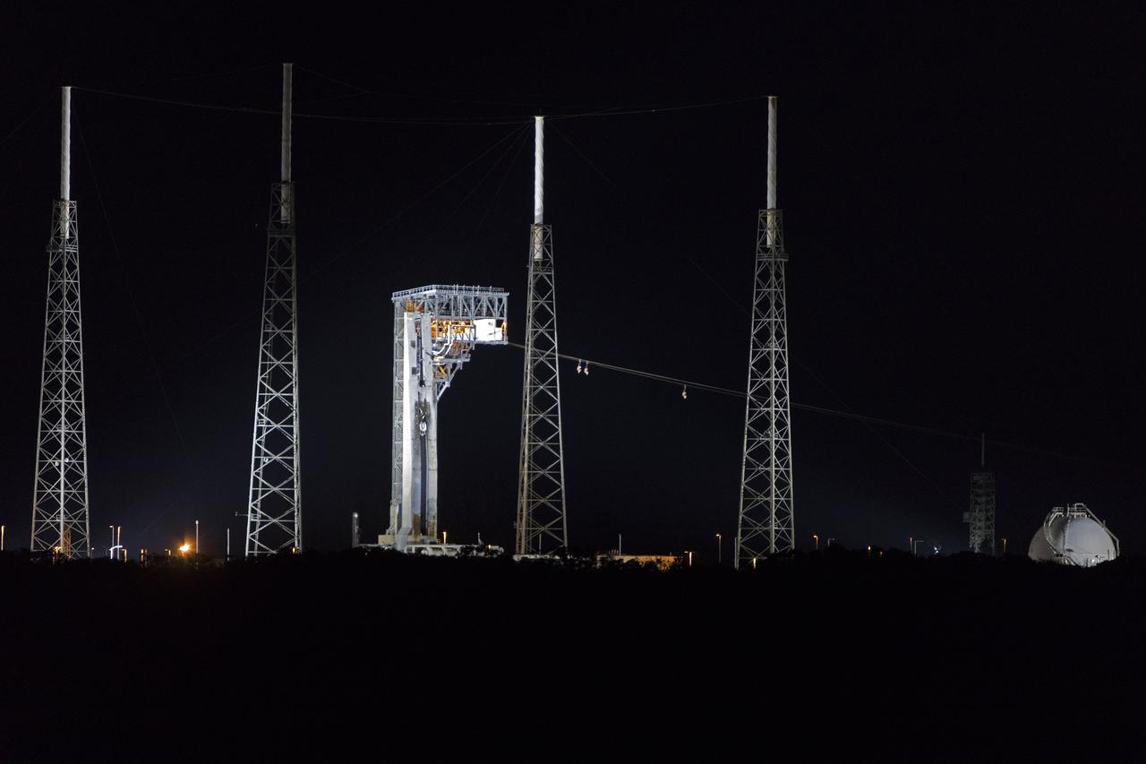
Commercial Crew astronauts test out the Boeing/United Launch Alliance (ULA) emergency egress system on June 19, 2018, at Cape Canaveral Air Force Station’s Launch Complex 41 in Florida. The emergency egress system provides an escape route in the unlikely event of an emergency prior to liftoff on launch day. It will be in place when Boeing’s CST-100 Starliner, launched aboard a ULA Atlas V rocket, carries astronauts to the International Space Station.
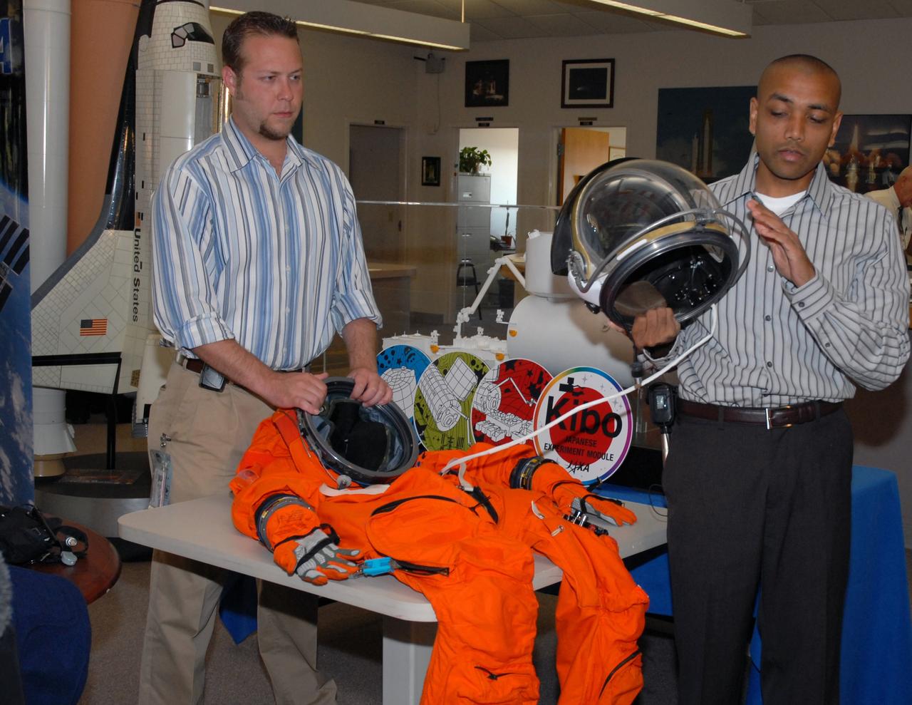
CAPE CANAVERAL, Fla. -- In the NASA News Center at NASA's Kennedy Space Center, Shuttle Crew Escape System Manager KC Chhipwadia (right) describes for the media the elements of the helmet that is part of the launch and entry suit (seen on the table) used by shuttle crews during their missions. The helmet provides oxygen when needed plus a communication system. Photo credit: NASA/Amanda Diller
CAPE CANAVERAL, Fla. -- In the NASA News Center at NASA's Kennedy Space Center, Shuttle Crew Escape System Manager KC Chhipwadia describes for the media the elements of the helmet that is part of the launch and entry suit (seen on the table) used by shuttle crews during their missions. The helmet provides oxygen when needed plus a communication system. Photo credit: NASA/Amanda Diller

jsc2011e002625 (01/11/2011)--- Training was performed at the Johnson Space Center to familiarize crew with emergency evacuation procedures from the shuttle system. Engineers at JSC (including Susana Tapia Harper & Alma Stephane Tapia) donned Advanced Crew Escape Space Suit System (ACES) suits while the astronaut crew practiced mock evacuations. NASA photo by James Blair
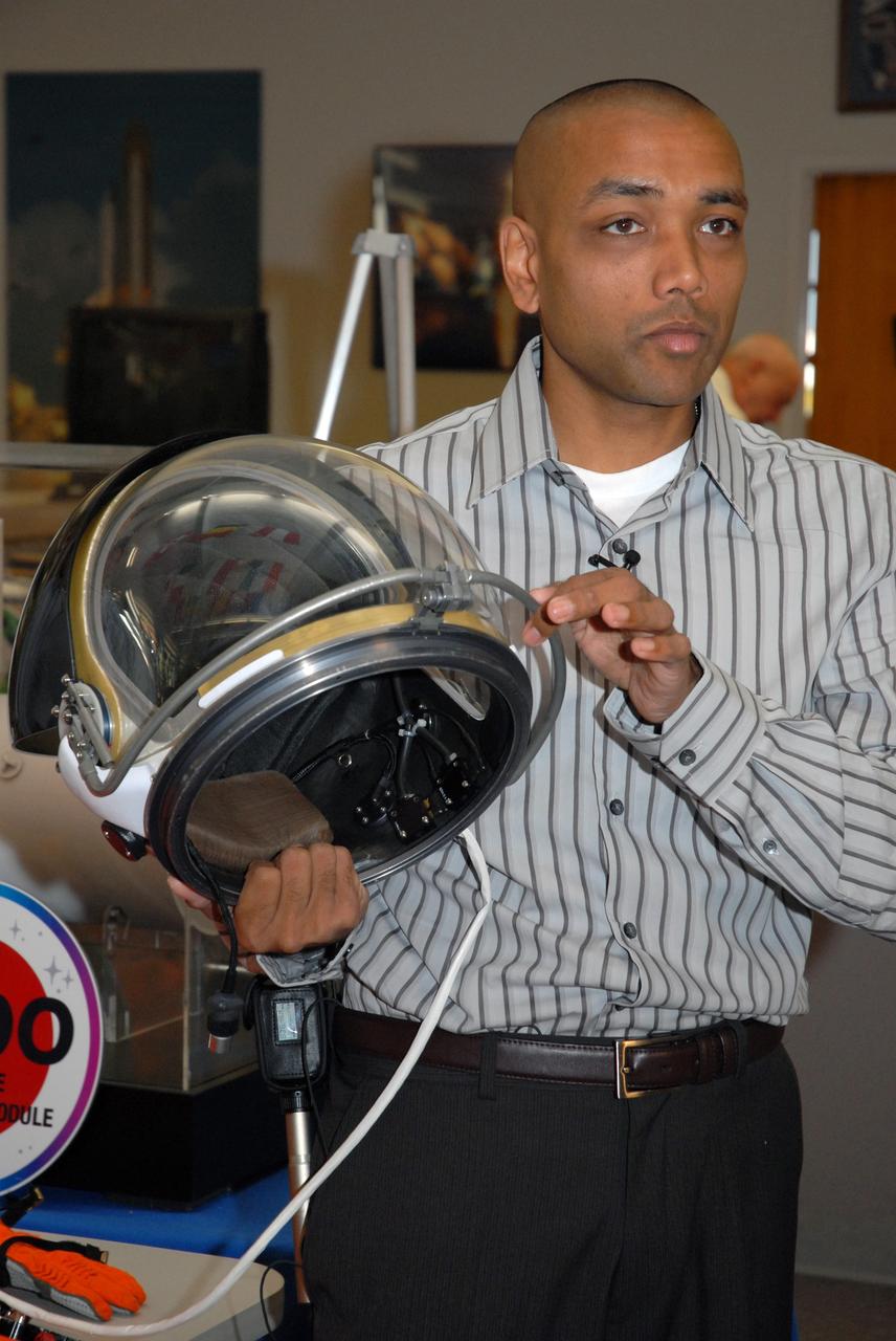
CAPE CANAVERAL, Fla. -- In the NASA News Center at NASA's Kennedy Space Center, Shuttle Crew Escape System Manager KC Chhipwadia describes for the media the elements of the helmet that is part of the launch and entry suit (seen on the table) used by shuttle crews during their missions. He is holding onto the bar that latches to secure the closed visor. The helmet provides oxygen when needed plus a communication system. Photo credit: NASA/Amanda Diller

Chris Ferguson, Boeing’s Director of Crew and Mission Operations for their Commercial Crew Program, is helped into his suit in preparation for a Boeing/United Launch Alliance emergency egress system demonstration on June 19, 2018. A veteran of three space shuttle missions, he commanded Atlantis in STS-135, the final mission of the Space Shuttle Program. The demonstration was held at Launch Complex 41 at Cape Canaveral Air Force Station in Florida. The emergency egress system provides an escape route in the unlikely event of an emergency on the launch pad on launch day.

jsc2011e002624 (01/11/2011)--- Training was performed at the Johnson Space Center to familiarize crew with emergency evacuation procedures from the shuttle system. Engineers at JSC (including Susana Tapia Harper & Alma Stephane Tapia) donned Advanced Crew Escape Space Suit System (ACES) suits while the astronaut crew practiced mock evacuations. NASA photo by James Blair
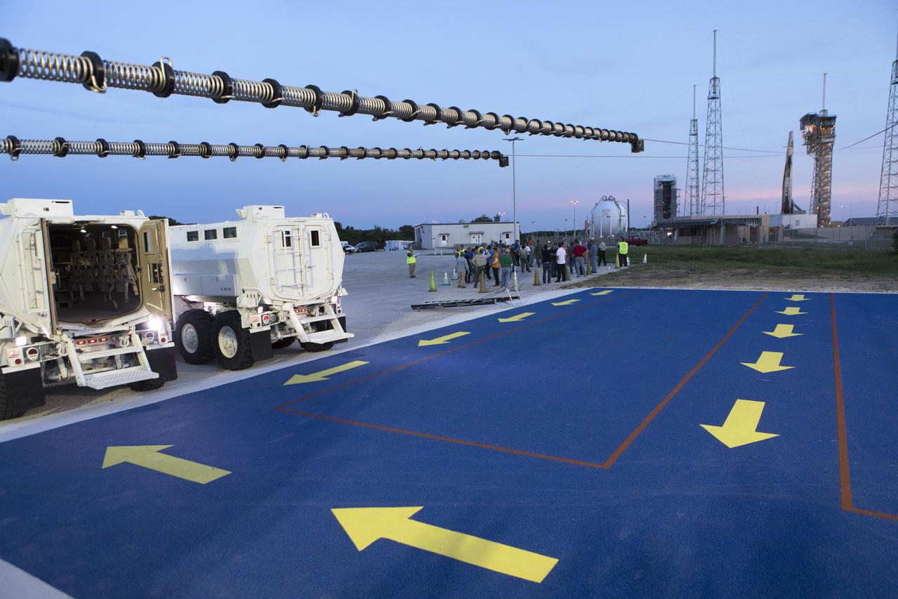
Two mine-resistant ambush protected vehicles, or MRAPs, sit ready to receive astronauts and ground crews during a Boeing/United Launch Alliance emergency egress system demonstration at Cape Canaveral Air Force Station’s Launch Complex 41 in Florida on June 19, 2018. The emergency egress system will provide an escape route in the unlikely event of an emergency on the launch pad on launch day.
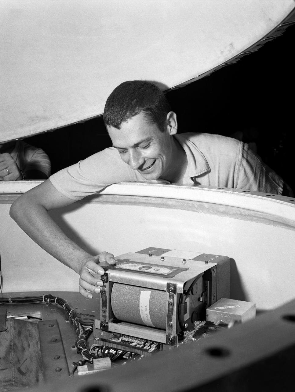
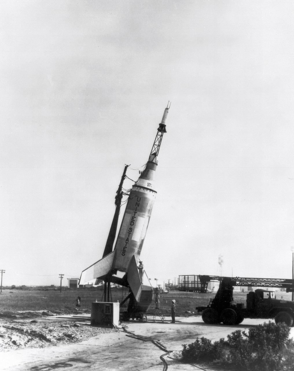
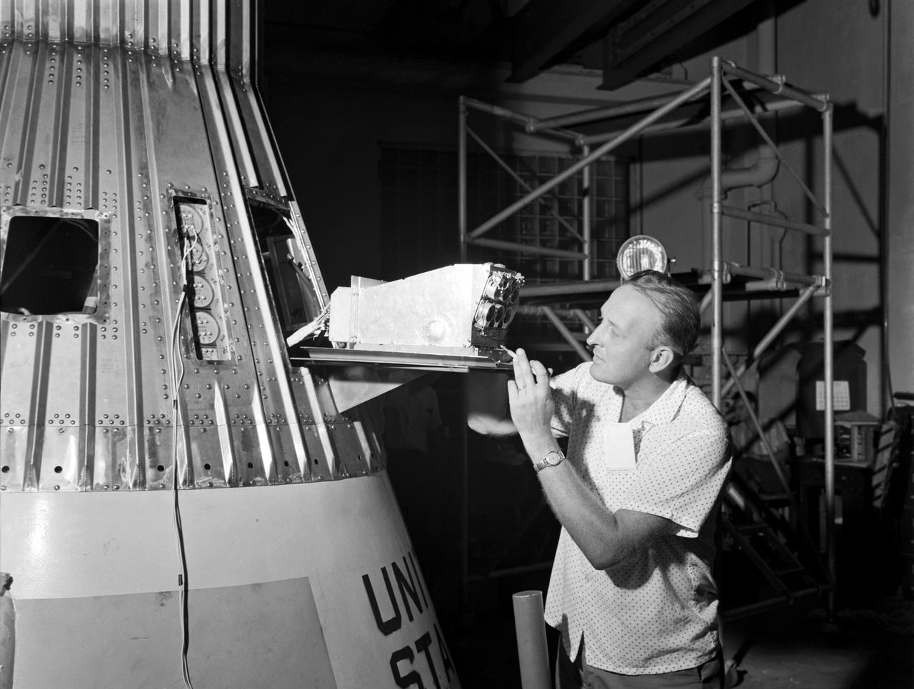
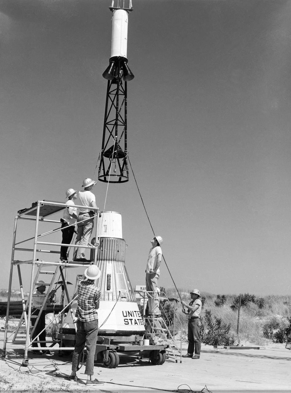
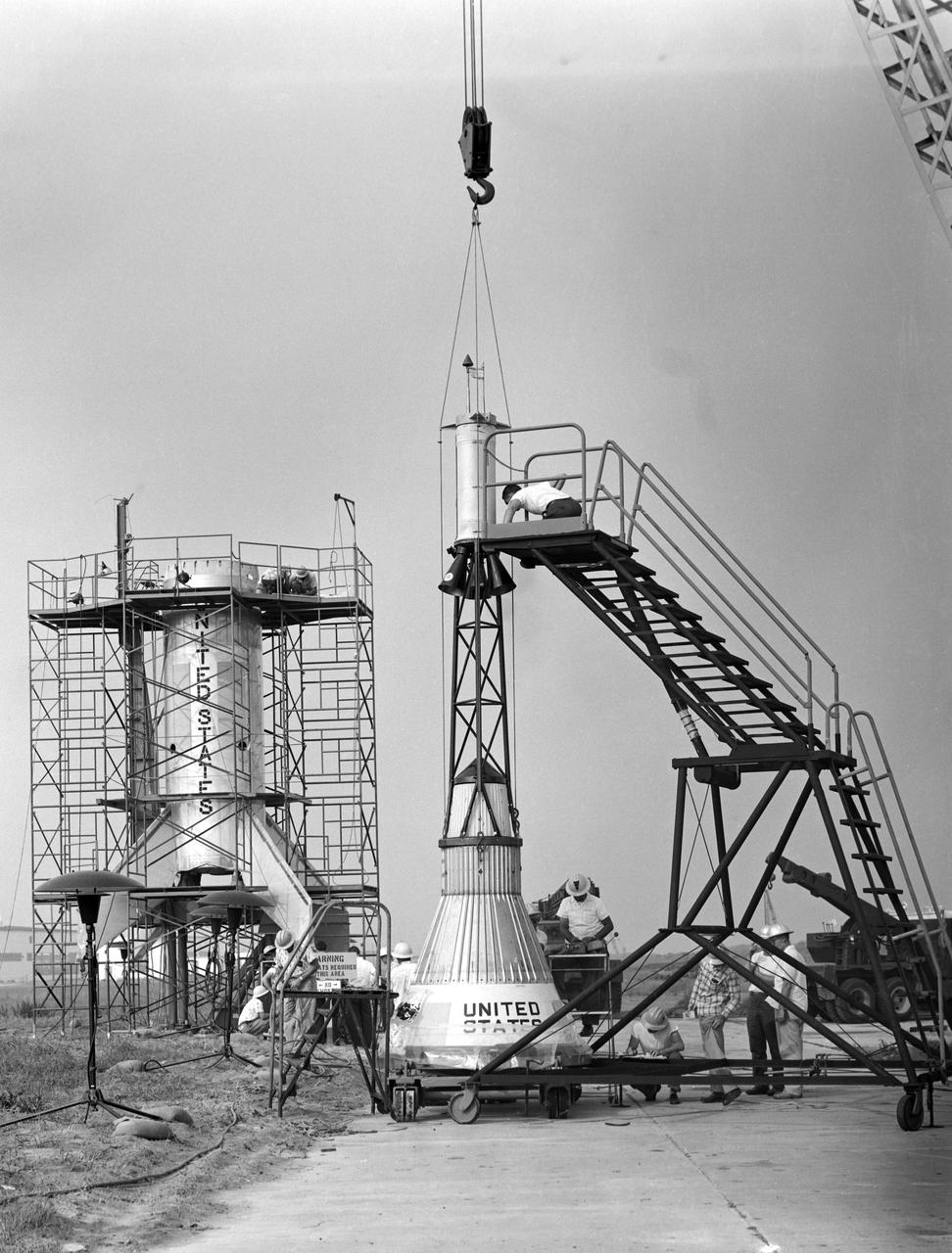
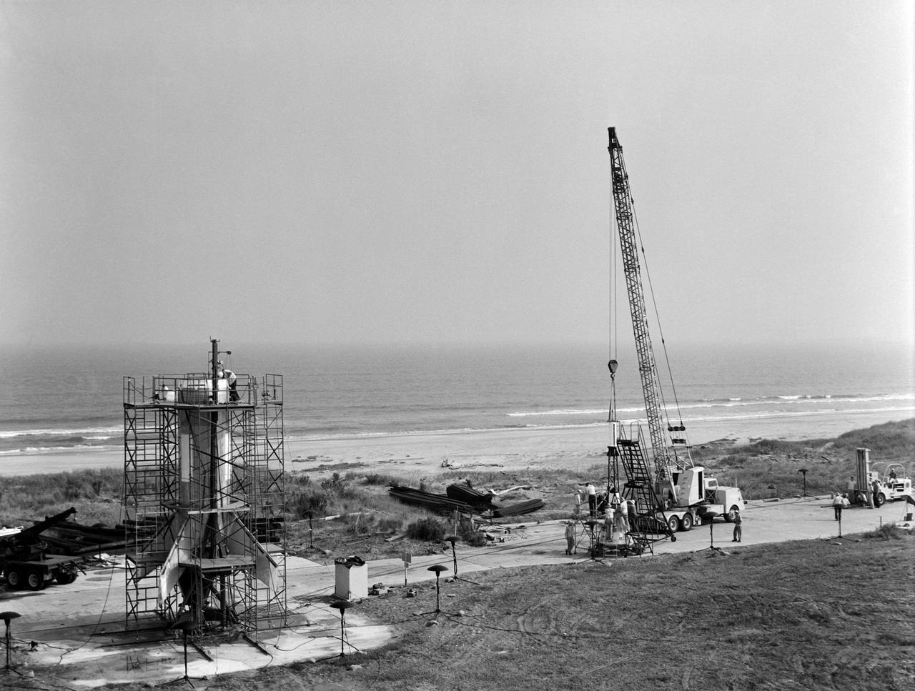
Technicians adjust the rocket motor during the attachment of the escape tower to the Mercury capsule prior to assembly with Little Joe launcher, August 20, 1959. Joseph Shortal wrote (vol. 3., p. 33): The escape tower and rocket motors were taken from the Mercury capsule production. The tower is shown being attached to the capsule.... The escape rocket was a Grand Central 1-KS-52000 motor with three canted nozzles. The tower-jettison motor was an Atlantic Research Corp. 1.4-KS-785 motor. This was the same design tested in a beach abort test...and had the offset thrust line as used in the beach abort test to insure that the capsule would get away from the booster in an emergency. The escape system weighed 1,015 pounds, including 236 pounds of ballast for stability. The Little Joe booster was assembled at Wallops on its special launcher in a vertical attitude. It is shown in the on the left with the work platform in place. The launcher was located on a special concrete slab in Launching Area 1. The capsule was lowered onto the booster by crane.... After the assembly was completed, the scaffolding was disassembled and the launcher pitched over to its normal launch angle of 80 degrees.... Little Joe had a diameter of 80 inches and an overall length, including the capsule and escape tower of 48 feet. The total weight at launch was about 43,000 pounds. The overall span of the stabilizing fins was 21.3 feet. Although in comparison with the overall Mercury Project, Little Joe was a simple undertaking, the fact that an attempt was made to condense a normal two-year project into a 6-month one with in house labor turned it into a major undertaking for Langley. -- Published in Joseph A. Shortal, History of Wallops Station: Origins and Activities Through 1949, (Wallops Island, VA: National Aeronautics and Space Administration, Wallops Station, nd), Comment Edition.
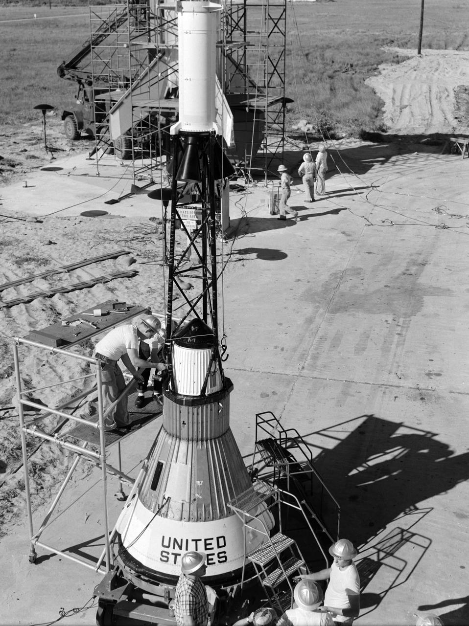
Technicians attach the escape tower to the Mercury capsule prior to assembly with Little Joe launcher, August 20, 1959. Joseph Shortal describe this as follows (vol. 3., p. 33): The escape tower and rocket motors were taken from the Mercury capsule production. The tower is shown being attached to the capsule.... The escape rocket was a Grand Central 1-KS-52000 motor with three canted nozzles. The tower-jettison motor was an Atlantic Research Corp. 1.4-KS-785 motor. This was the same design tested in a beach abort test...and had the offset thrust line as used in the beach abort test to insure that the capsule would get away from the booster in an emergency. The escape system weighed 1,015 pounds, including 236 pounds of ballast for stability. The Little Joe booster was assembled at Wallops on its special launcher in a vertical attitude. It is shown in the on the left with the work platform in place. The launcher was located on a special concrete slab in Launching Area 1. The capsule was lowered onto the booster by crane.... After the assembly was completed, the scaffolding was disassembled and the launcher pitched over to its normal launch angle of 80 degrees.... Little Joe had a diameter of 80 inches and an overall length, including the capsule and escape tower of 48 feet. The total weight at launch was about 43,000 pounds. The overall span of the stabilizing fins was 21.3 feet. Although in comparison with the overall Mercury Project, Little Joe was a simple undertaking, the fact that an attempt was made to condense a normal two-year project into a 6-month one with in house labor turned it into a major undertaking for Langley. -- Published in Joseph A. Shortal, History of Wallops Station: Origins and Activities Through 1949, (Wallops Island, VA: National Aeronautics and Space Administration, Wallops Station, nd), Comment Edition.

Technicians adjust the rocket motor during the attachment of the escape tower to the Mercury capsule prior to assembly with Little Joe launcher, August 20, 1959. Joseph Shortal wrote (vol. 3., p. 33): The escape tower and rocket motors were taken from the Mercury capsule production. The tower is shown being attached to the capsule.... The escape rocket was a Grand Central 1-KS-52000 motor with three canted nozzles. The tower-jettison motor was an Atlantic Research Corp. 1.4-KS-785 motor. This was the same design tested in a beach abort test...and had the offset thrust line as used in the beach abort test to insure that the capsule would get away from the booster in an emergency. The escape system weighed 1,015 pounds, including 236 pounds of ballast for stability. The Little Joe booster was assembled at Wallops on its special launcher in a vertical attitude. It is shown in the on the left with the work platform in place. The launcher was located on a special concrete slab in Launching Area 1. The capsule was lowered onto the booster by crane.... After the assembly was completed, the scaffolding was disassembled and the launcher pitched over to its normal launch angle of 80 degrees.... Little Joe had a diameter of 80 inches and an overall length, including the capsule and escape tower of 48 feet. The total weight at launch was about 43,000 pounds. The overall span of the stabilizing fins was 21.3 feet. Although in comparison with the overall Mercury Project, Little Joe was a simple undertaking, the fact that an attempt was made to condense a normal two-year project into a 6-month one with in house labor turned it into a major undertaking for Langley. -- Published in Joseph A. Shortal, History of Wallops Station: Origins and Activities Through 1949, (Wallops Island, VA: National Aeronautics and Space Administration, Wallops Station, nd), Comment Edition.
Technicians adjust the rocket motor during the attachment of the escape tower to the Mercury capsule prior to assembly with Little Joe launcher, August 20, 1959. Joseph Shortal wrote (vol. 3., p. 33): The escape tower and rocket motors were taken from the Mercury capsule production. The tower is shown being attached to the capsule.... The escape rocket was a Grand Central 1-KS-52000 motor with three canted nozzles. The tower-jettison motor was an Atlantic Research Corp. 1.4-KS-785 motor. This was the same design tested in a beach abort test...and had the offset thrust line as used in the beach abort test to insure that the capsule would get away from the booster in an emergency. The escape system weighed 1,015 pounds, including 236 pounds of ballast for stability. The Little Joe booster was assembled at Wallops on its special launcher in a vertical attitude. It is shown in the on the left with the work platform in place. The launcher was located on a special concrete slab in Launching Area 1. The capsule was lowered onto the booster by crane.... After the assembly was completed, the scaffolding was disassembled and the launcher pitched over to its normal launch angle of 80 degrees.... Little Joe had a diameter of 80 inches and an overall length, including the capsule and escape tower of 48 feet. The total weight at launch was about 43,000 pounds. The overall span of the stabilizing fins was 21.3 feet. Although in comparison with the overall Mercury Project, Little Joe was a simple undertaking, the fact that an attempt was made to condense a normal two-year project into a 6-month one with in house labor turned it into a major undertaking for Langley. -- Published in Joseph A. Shortal, History of Wallops Station: Origins and Activities Through 1949, (Wallops Island, VA: National Aeronautics and Space Administration, Wallops Station, nd), Comment Edition.
Technicians attach the escape tower to the Mercury capsule prior to assembly with Little Joe launcher, August 20, 1959. Joseph Shortal describe this as follows (vol. 3., p. 33): The escape tower and rocket motors were taken from the Mercury capsule production. The tower is shown being attached to the capsule.... The escape rocket was a Grand Central 1-KS-52000 motor with three canted nozzles. The tower-jettison motor was an Atlantic Research Corp. 1.4-KS-785 motor. This was the same design tested in a beach abort test...and had the offset thrust line as used in the beach abort test to insure that the capsule would get away from the booster in an emergency. The escape system weighed 1,015 pounds, including 236 pounds of ballast for stability. The Little Joe booster was assembled at Wallops on its special launcher in a vertical attitude. It is shown in the on the left with the work platform in place. The launcher was located on a special concrete slab in Launching Area 1. The capsule was lowered onto the booster by crane.... After the assembly was completed, the scaffolding was disassembled and the launcher pitched over to its normal launch angle of 80 degrees.... Little Joe had a diameter of 80 inches and an overall length, including the capsule and escape tower of 48 feet. The total weight at launch was about 43,000 pounds. The overall span of the stabilizing fins was 21.3 feet. Although in comparison with the overall Mercury Project, Little Joe was a simple undertaking, the fact that an attempt was made to condense a normal two-year project into a 6-month one with in house labor turned it into a major undertaking for Langley. -- Published in Joseph A. Shortal, History of Wallops Station: Origins and Activities Through 1949, (Wallops Island, VA: National Aeronautics and Space Administration, Wallops Station, nd), Comment Edition.