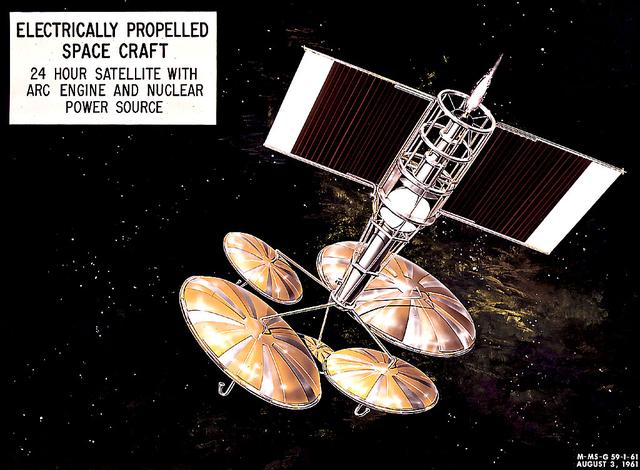
This 1960 artist's concept shows a 24-hour communication satellite design incorporating an arc engine with a nuclear power source. The concept was one of many missions proposed by the Marshall Space Flight Center for electrically-propelled spacecraft.
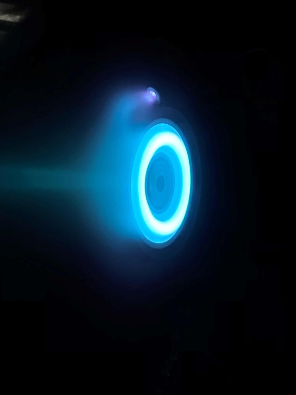
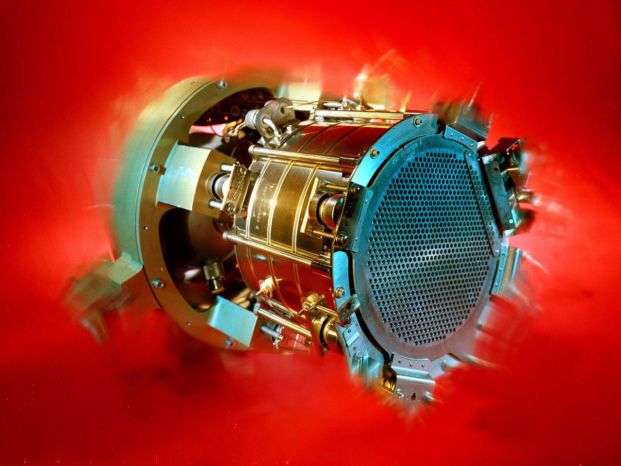
NASA's Psyche spacecraft, set to launch in August 2022, will travel to its target in the main asteroid belt between Mars and Jupiter under the power of super-efficient electric propulsion. This photo captures an operating electric Hall thruster identical to those that will be used to propel the Psyche spacecraft. This photo was taken at NASA's Jet Propulsion Laboratory in Southern California on May 20, 2020 with an iPhone, through the thick window of a vacuum chamber used to simulate the environment of deep space. The thruster works by turning xenon gas, a neutral gas used in car headlights and plasma TVs, into xenon ions. As the xenon ions are accelerated out of the thruster, they create the thrust that will propel the spacecraft. The xenon plasma emits a blue glow, seen here, as it operates. An observer in space traveling behind Psyche would see the blue glow of plasma trailing behind the spacecraft. Solar arrays will provide the electricity that powers the thrusters. Hall thrusters will be used for the first time beyond lunar orbit, demonstrating that they could play a role in supporting future missions to deep space. https://photojournal.jpl.nasa.gov/catalog/PIA23879
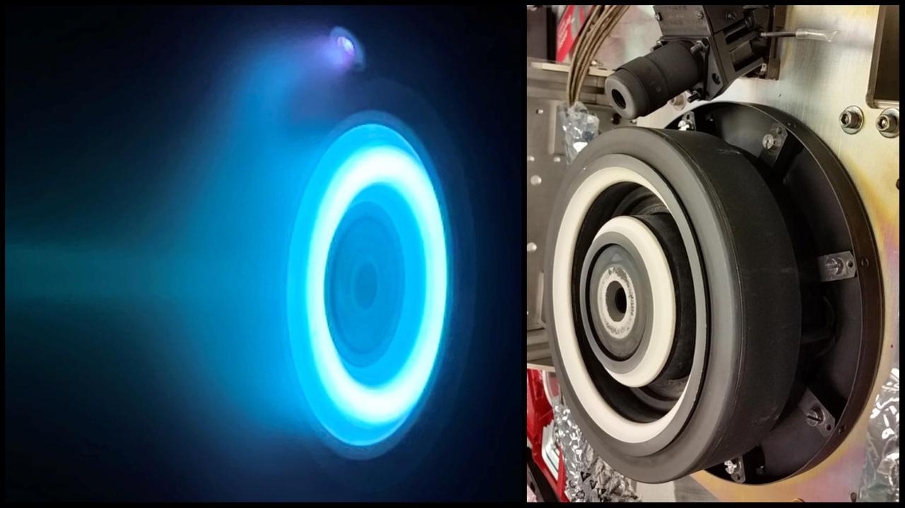
The photo on the left captures an operating electric Hall thruster identical to those that will propel NASA's Psyche spacecraft, which is set to launch in August 2022 and travel to the main asteroid belt between Mars and Jupiter. The xenon plasma emits a blue glow as the thruster operates. The photo on the right shows a similar non-operating Hall thruster. The photo on the left was taken at NASA's Jet Propulsion Laboratory in Southern California; the photo on the right was taken at NASA's Glenn Research Center. Psyche's Hall thrusters will be the first to be used beyond lunar orbit, demonstrating that they could play a role in supporting future missions to deep space. The spacecraft is set to launch in August 2022 and will travel to its target, a metal-rich asteroid also named Psyche, under the power of solar electric propulsion. This super-efficient mode of propulsion uses solar arrays to capture sunlight that is converted into electricity to power the spacecraft's thrusters. The thrusters work by turning xenon gas, a neutral gas used in car headlights and plasma TVs, into xenon ions. As the xenon ions are accelerated out of the thruster, they create the thrust that will propel the spacecraft. https://photojournal.jpl.nasa.gov/catalog/PIA24030
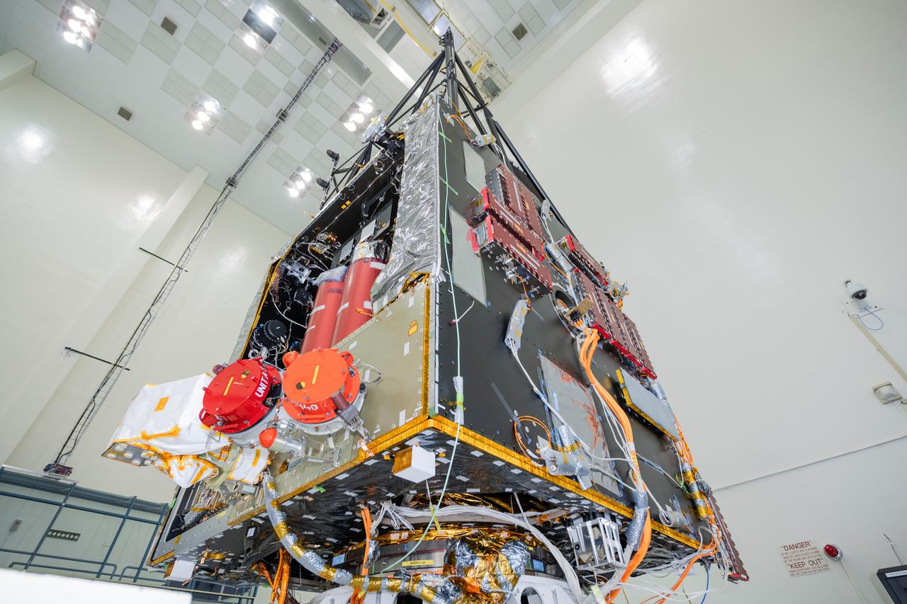
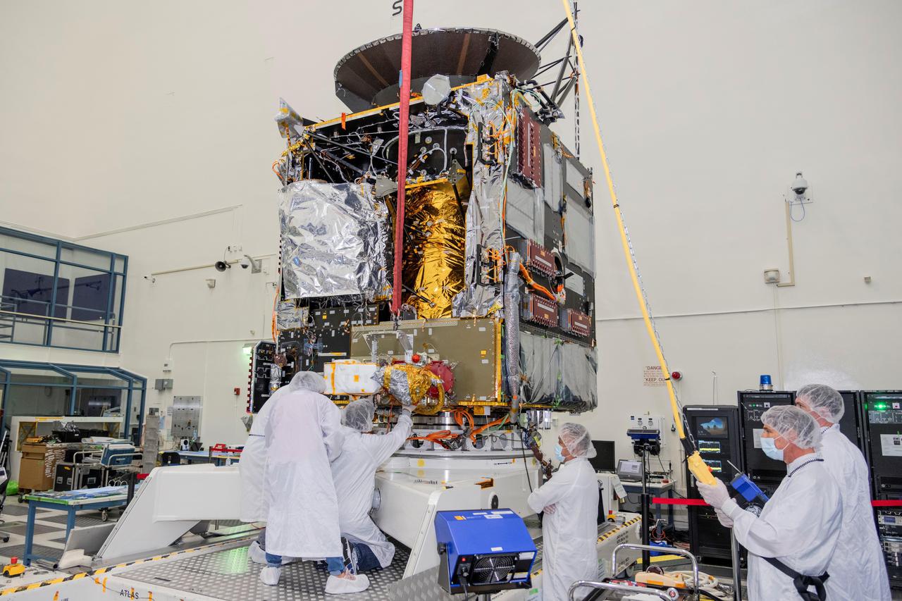
NASA's Psyche spacecraft is photographed in July 2021 during the mission's assembly, test, and launch operations phase at the agency's Jet Propulsion Laboratory in Southern California. Set to launch in August 2022, the spacecraft will use four Hall thrusters to propel itself to the metal-rich asteroid Psyche, using solar electric propulsion. Two thrusters are visible beneath red round protective covers, after being integrated into the spacecraft. Solar arrays on the spacecraft will capture sunlight, which will be converted into electricity to power the Hall thrusters. The thrusters work by turning xenon gas, a neutral gas used in car headlights and plasma TVs, into xenon ions. As the xenon ions are accelerated out of the thruster, they create the thrust that will propel the spacecraft. This will be the first use of Hall thrusters beyond lunar orbit, demonstrating that they could play a role in supporting future deep space missions. https://photojournal.jpl.nasa.gov/catalog/PIA24790

Interior of the 20-foot diameter vacuum tank at the NASA Lewis Research Center’s Electric Propulsion Laboratory. Lewis researchers had been studying different electric rocket propulsion methods since the mid-1950s. Harold Kaufman created the first successful ion engine, the electron bombardment ion engine, in the early 1960s. These engines used electric power to create and accelerate small particles of propellant material to high exhaust velocities. Electric engines have a very small thrust, but can operate for long periods of time. The ion engines are often clustered together to provide higher levels of thrust. The Electric Propulsion Laboratory, which began operation in 1961, contained two large vacuum tanks capable of simulating a space environment. The tanks were designed especially for testing ion and plasma thrusters and spacecraft. The larger 25-foot diameter tank included a 10-foot diameter test compartment to test electric thrusters with condensable propellants. The portals along the chamber floor lead to the massive exhauster equipment that pumped out the air to simulate the low pressures found in space.
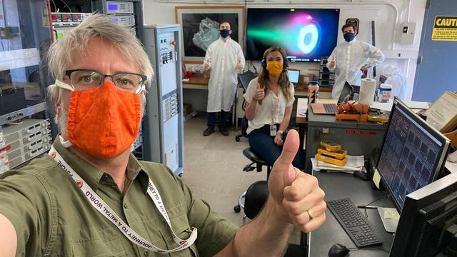
Psyche engineers adapted to COVID-19 social distancing and masking requirements while testing the Hall thrusters that will propel NASA's Psyche spacecraft on its journey to the main asteroid belt between Mars and Jupiter. Set to launch in August 2022, the spacecraft will utilize this super-efficient electric propulsion system to travel to the asteroid Psyche. On May 20, 2020, at NASA's Jet Propulsion Laboratory, Flight System Engineer Steve Snyder (foreground) of JPL and a crew of engineers from Maxar Technologies worked together in the control room next to the vacuum chamber where the thruster was fired up. Snyder and his Maxar colleagues (from left: Faraz Aghazadeh, Taylor Kerl and Giovanni Lenguito) put the thruster and its power supply through a series of stress tests to ensure they can operate together in the extreme conditions of deep space. In the background, a monitor projects the image of the thruster firing. The thruster works by turning xenon gas, a neutral gas used in car headlights and plasma TVs, into xenon ions. As the xenon ions are accelerated out of the thruster, they create the thrust that will propel the spacecraft. The xenon plasma emits a blue glow, seen here on the screen, as it operates. Hall thrusters will be used for the first time beyond lunar orbit, demonstrating that they could play a role in supporting future missions to deep space. Maxar and JPL adapted the Hall thruster system for use with the main body of the spacecraft that Maxar is building at its facility in Palo Alto, California. https://photojournal.jpl.nasa.gov/catalog/PIA23878
Engineers at NASA's Jet Propulsion Laboratory in Southern California work to integrate Hall thrusters into the agency's Psyche spacecraft in this July 2021 photo. One of the thrusters is visible on the side of the spacecraft beneath a red protective cover. Psyche is set to launch in August 2022 and will travel to its target, a metal-rich asteroid also named Psyche, under the power of solar electric propulsion. This super-efficient mode of propulsion uses solar arrays to capture sunlight that is converted into electricity to power the spacecraft's Hall thrusters. They work by turning xenon gas, a neutral gas used in car headlights and plasma TVs, into xenon ions. As the xenon ions are accelerated out of the thruster, they create the thrust that will propel the spacecraft. This will be the first use of Hall thrusters beyond lunar orbit, demonstrating that they could play a role in supporting future deep space missions. https://photojournal.jpl.nasa.gov/catalog/PIA24789
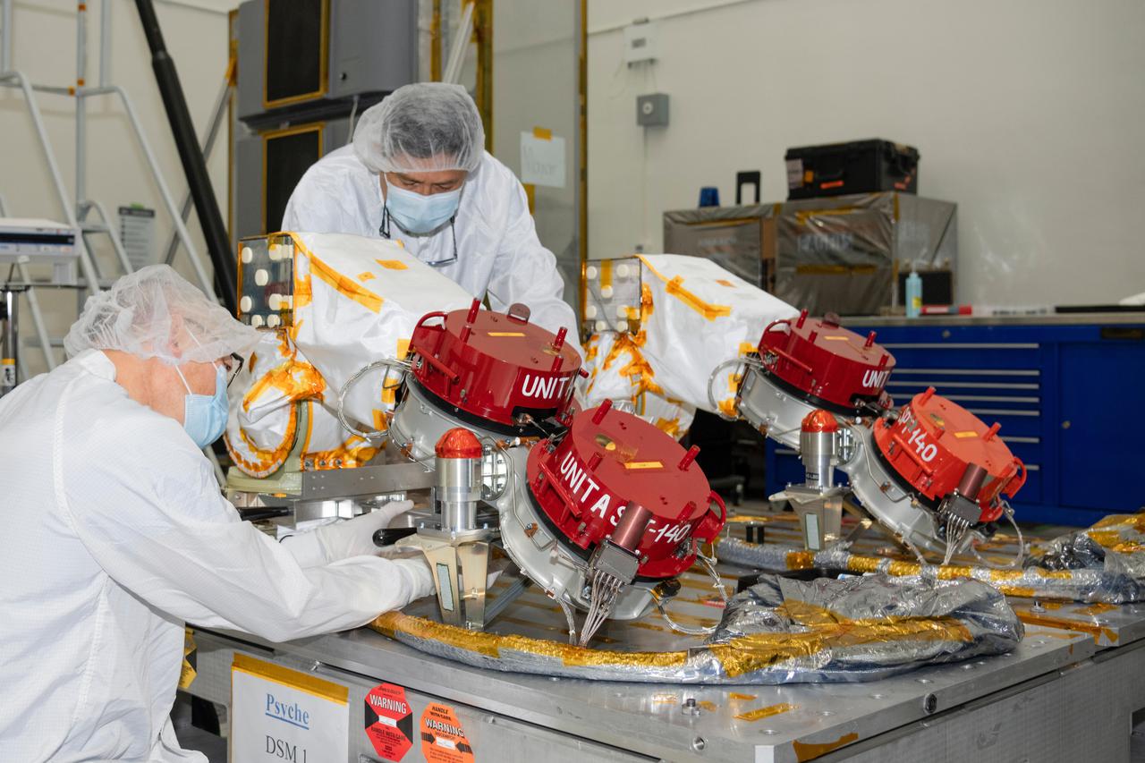
Engineers at NASA's Jet Propulsion Laboratory in Southern California prepare to integrate four Hall thrusters (beneath red protective covers) into the agency's Psyche spacecraft in July 2021. Psyche is set to launch in August 2022 and will travel to its target, a metal-rich asteroid also named Psyche, under the power of solar electric propulsion. This super-efficient mode of propulsion uses solar arrays to capture sunlight that is converted into electricity to power the spacecraft's thrusters. The thrusters work by turning xenon gas, a neutral gas used in car headlights and plasma TVs, into xenon ions. As the xenon ions are accelerated out of the thruster, they create the thrust that will propel the spacecraft. On the Psyche spacecraft, Hall thrusters will be used for the first time beyond lunar orbit, demonstrating that they could play a role in supporting future missions to deep space. https://photojournal.jpl.nasa.gov/catalog/PIA24788
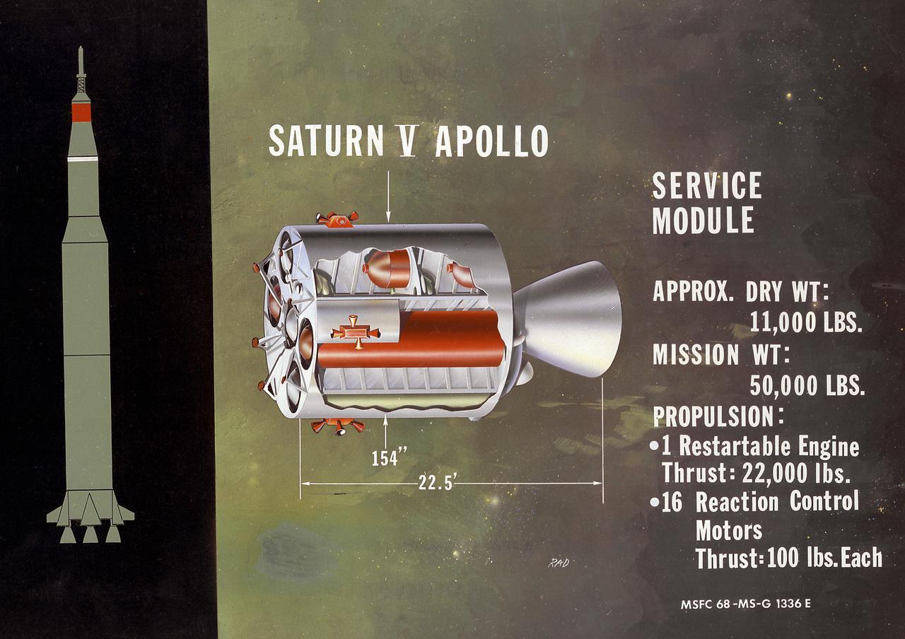
This is a cutaway illustration of the Saturn V service module configuration. Packed with plumbing and tanks, the service module was the command module's constant companion until just before reentry. All components not needed during the last few minutes of flight, and therefore requiring no protection against reentry heat, were transported in this module. It carried oxygen for most of the trip, fuel cells to generate electricity (along with the oxygen and hydrogen to run them); small engines to control pitch, roll, and yaw; and a large engine to propel the spacecraft into, and out of, lunar orbit.
Researchers at the Lewis Research Center had been studying different methods of electric rocket propulsion since the mid-1950s. Harold Kaufman created the first successful engine, the electron bombardment ion engine, in the early 1960s. Over the ensuing decades Lewis researchers continued to advance the original ion thruster concept. A Space Electric Rocket Test (SERT) spacecraft was launched in June 1964 to test Kaufman’s engine in space. SERT I had one cesium engine and one mercury engine. The suborbital flight was only 50 minutes in duration but proved that the ion engine could operate in space. This was followed in 1966 by the even more successful SERT II, which operated on and off for over ten years. Lewis continued studying increasingly more powerful ion thrusters. These electric engines created and accelerated small particles of propellant material to high exhaust velocities. Electric engines have a very small amount of thrust and are therefore not capable of lifting a spaceship from the surface of the Earth. Once lofted into orbit, however, electric engines are can produce small, continuous streams of thrust for several years.

New staff member Paul Margosian inspects a cluster of ion engines in the Electric Propulsion Laboratory’s 25-foot diameter vacuum tank at the National Aeronautics and Space Administration (NASA) Lewis Research Center. Lewis researchers had been studying different methods of electric rocket propulsion since the mid-1950s. Harold Kaufman created the first successful engine, the electron bombardment ion engine, in the early 1960s. These engines used electric power to create and accelerate small particles of propellant material to high exhaust velocities. Electric engines have a very small thrust, and but can operate for long periods of time. The ion engines are often clustered together to provide higher levels of thrust. The Electric Propulsion Laboratory contained two large vacuum tanks capable of simulating the space environment. The tanks were designed especially for testing ion and plasma thrusters and spacecraft. The larger 25-foot diameter tank was intended for testing electric thrusters with condensable propellants. The tank’s test compartment, seen here, was 10 feet in diameter. Margosian joined Lewis in late 1962 during a major NASA hiring phase. The Agency reorganized in 1961 and began expanding its ranks through a massive recruiting effort. Lewis personnel increased from approximately 2,700 in 1961 to over 4,800 in 1966. Margosian, who worked with Bill Kerslake in the Electromagnetic Propulsion Division’s Propulsion Systems Section, wrote eight technical reports on mercury and electron bombardment thrusters, thermoelectrostatic generators, and a high voltage insulator.

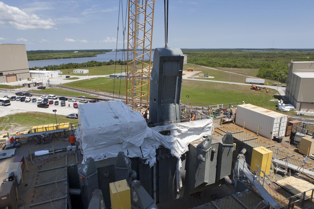
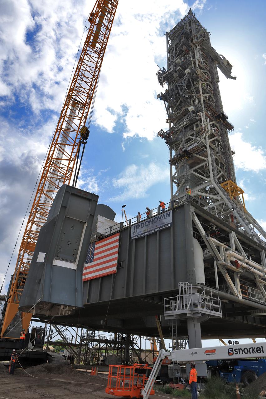
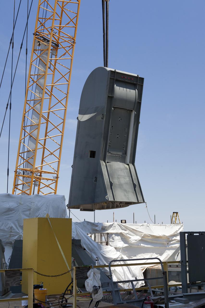
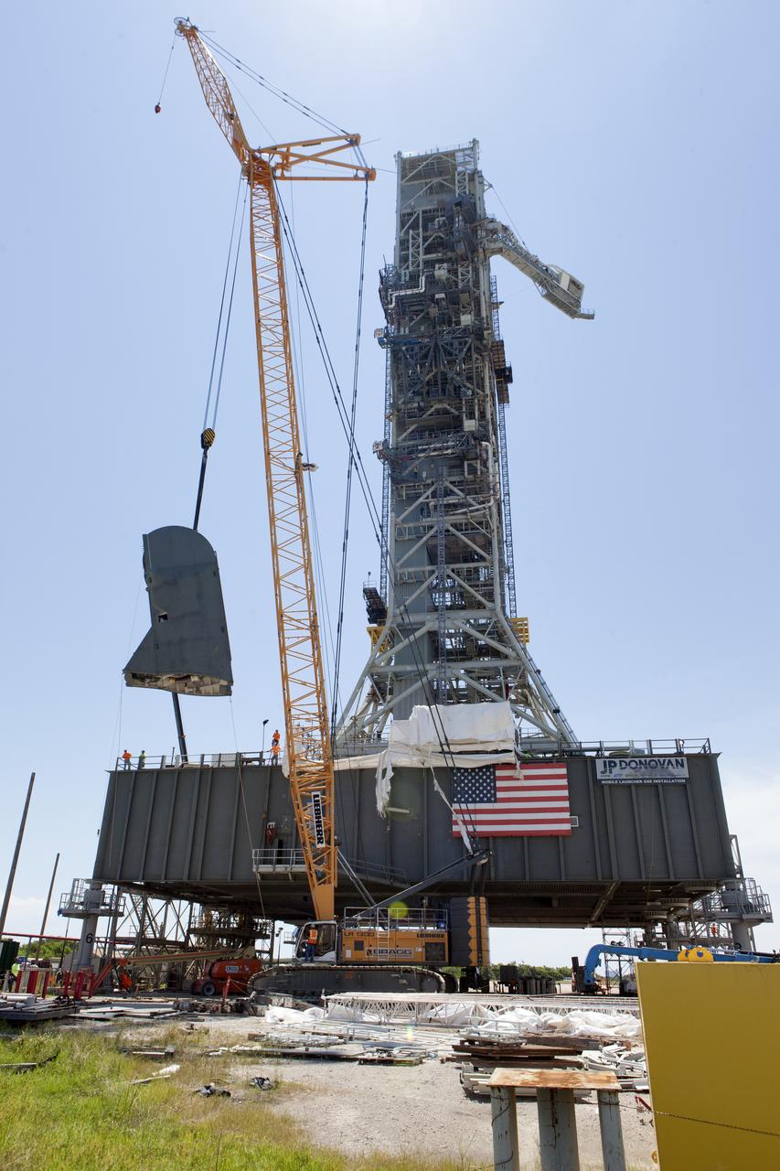
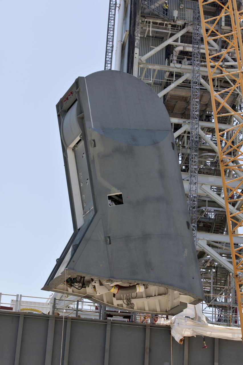
The second of two Tail Service Mast Umbilicals (TSMU), at left, is lowered for installation on the 0-level deck of the mobile launcher on July 27, at NASA's Kennedy Space Center in Florida. The 35-foot-tall umbilical will connect to NASA's Space Launch System (SLS) rocket core stage aft section and provide liquid hydrogen and electrical cable connections to the core stage engine section to support propellant handling during prelaunch operations. In view at right is the TSMU that will provide liquid oxygen and electrical cable connections to the core stage engine section. The installation brings Exploration Ground Systems one step closer to supporting prelaunch operations for the agency's SLS rocket and Orion spacecraft on Exploration Mission-1 and deep space destinations.
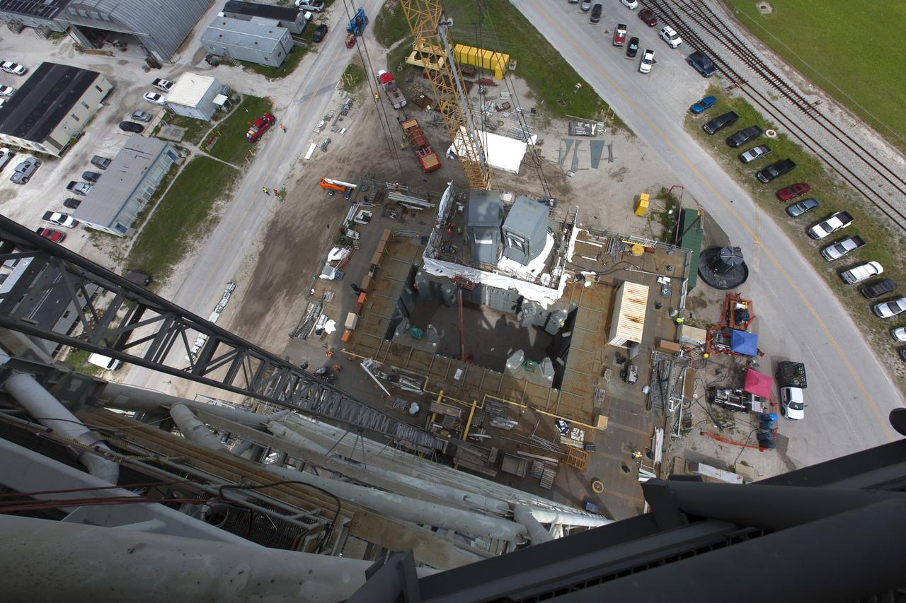
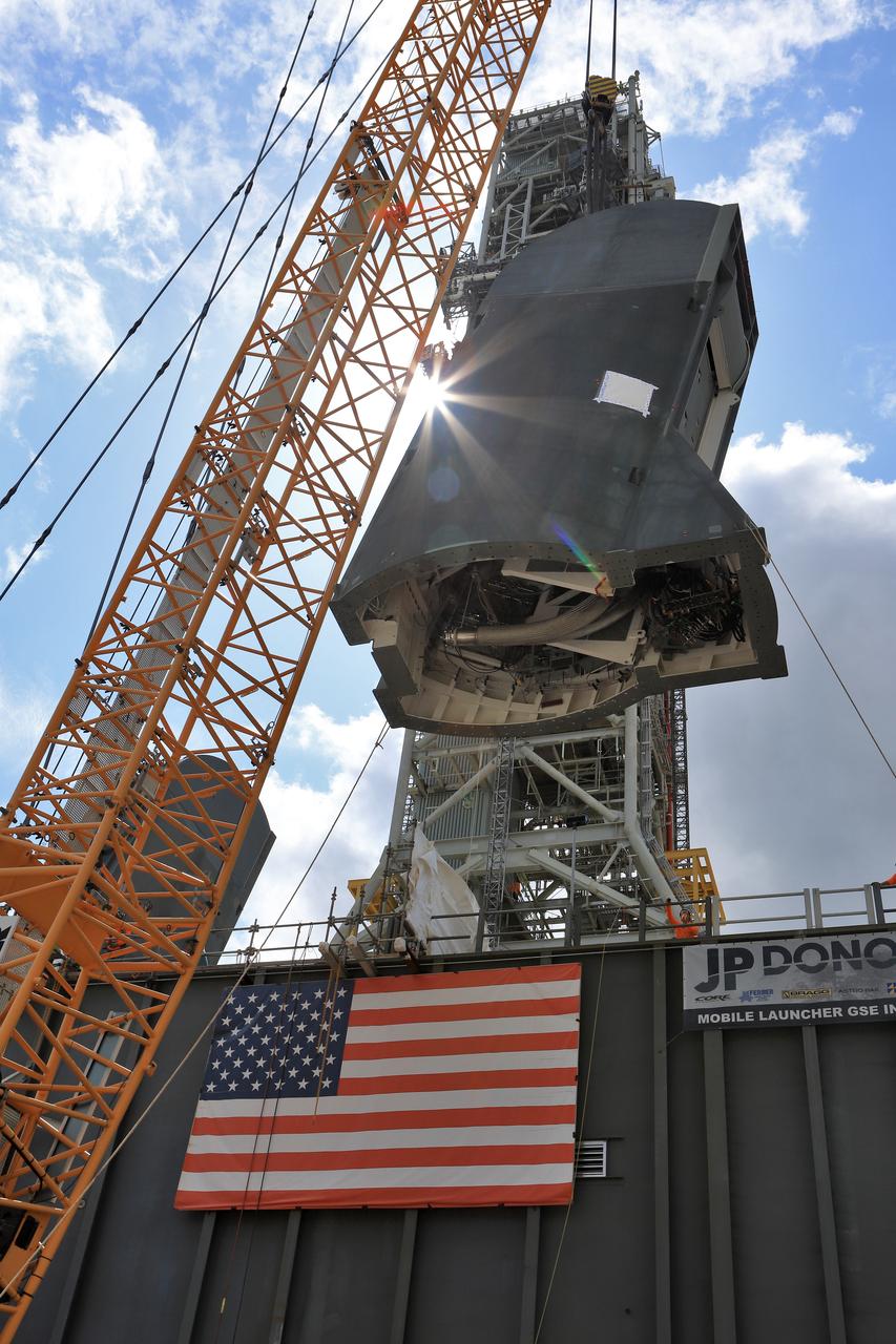
In this view from high above on the mobile launcher tower, a crane is used to lower the second of two Tail Service Mast Umbilicals (TSMU) for installation on the 0-level deck of the mobile launcher on July 27, at NASA's Kennedy Space Center in Florida. The 35-foot-tall umbilical will connect to NASA's Space Launch System rocket core stage aft section and provide liquid hydrogen and electrical cable connections to the core stage engine section to support propellant handling during prelaunch operations. In view at right is the TSMU that will provide liquid oxygen and electrical cable connections to the core stage engine section. The installation brings Exploration Ground Systems one step closer to supporting prelaunch operations for the agency's SLS rocket and Orion spacecraft on Exploration Mission-1 and deep space destinations.
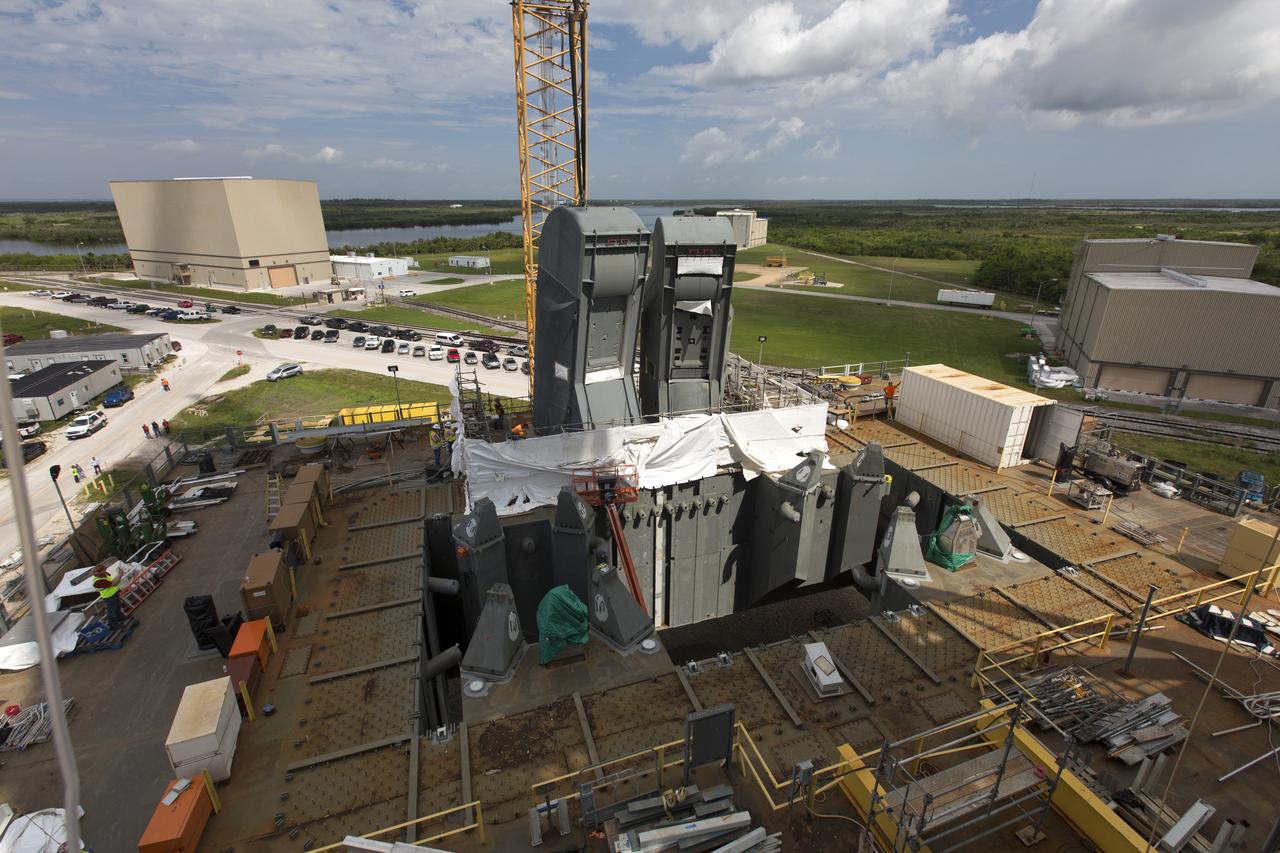
The second of two Tail Service Mast Umbilicals (TSMU), at left, is lowered for installation on the 0-level deck of the mobile launcher on July 27, at NASA's Kennedy Space Center in Florida. The 35-foot-tall umbilical will connect to NASA's Space Launch System (SLS) rocket core stage aft section and provide liquid hydrogen and electrical cable connections to the core stage engine section to support propellant handling during prelaunch operations. In view at right is the TSMU that will provide liquid oxygen and electrical cable connections to the core stage engine section. The installation brings Exploration Ground Systems one step closer to supporting prelaunch operations for the agency's SLS rocket and Orion spacecraft on Exploration Mission-1 and deep space destinations.
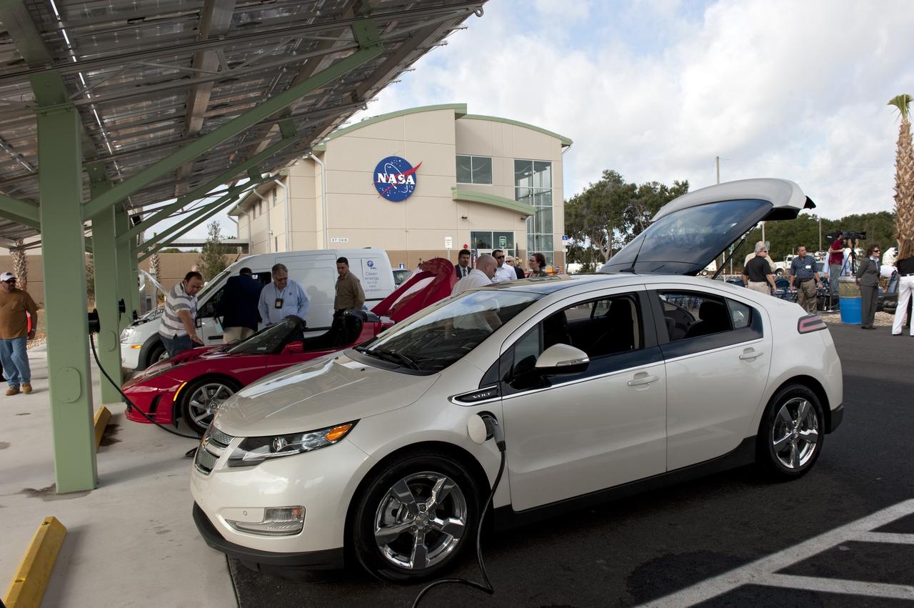
CAPE CANAVERAL, Fla. -- NASA's Kennedy Space Center in Florida hosts a ribbon-cutting ceremony for its new environmentally friendly Propellants North Administrative and Maintenance Facility. This is a view of the parking lot where a solar-powered charging canopy is available for powering government or privately owned electric vehicles. Propellants North consists of two buildings, one to store cryogenic fuel transfer equipment and one to house personnel who support fueling spacecraft. The recently rebuilt buildings will be NASA's first carbon neutral facility, which means it will produce enough energy on site from renewable sources to offset what it requires to operate. The facility also will reach for the U.S. Green Building Council's Leadership in Environmental and Energy Design (LEED) Platinum status, which is the highest LEED rating. Photo credit: NASA/Kim Shiflett
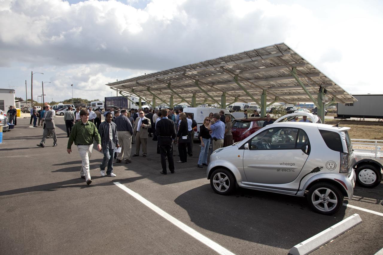
CAPE CANAVERAL, Fla. -- NASA's Kennedy Space Center in Florida hosts a ribbon-cutting ceremony for its new environmentally friendly Propellants North Administrative and Maintenance Facility. This is a view of the parking lot where a solar-powered charging canopy is available for powering government or privately owned electric vehicles. Propellants North consists of two buildings, one to store cryogenic fuel transfer equipment and one to house personnel who support fueling spacecraft. The recently rebuilt buildings will be NASA's first carbon neutral facility, which means it will produce enough energy on site from renewable sources to offset what it requires to operate. The facility also will reach for the U.S. Green Building Council's Leadership in Environmental and Energy Design (LEED) Platinum status, which is the highest LEED rating. Photo credit: NASA/Frankie Martin
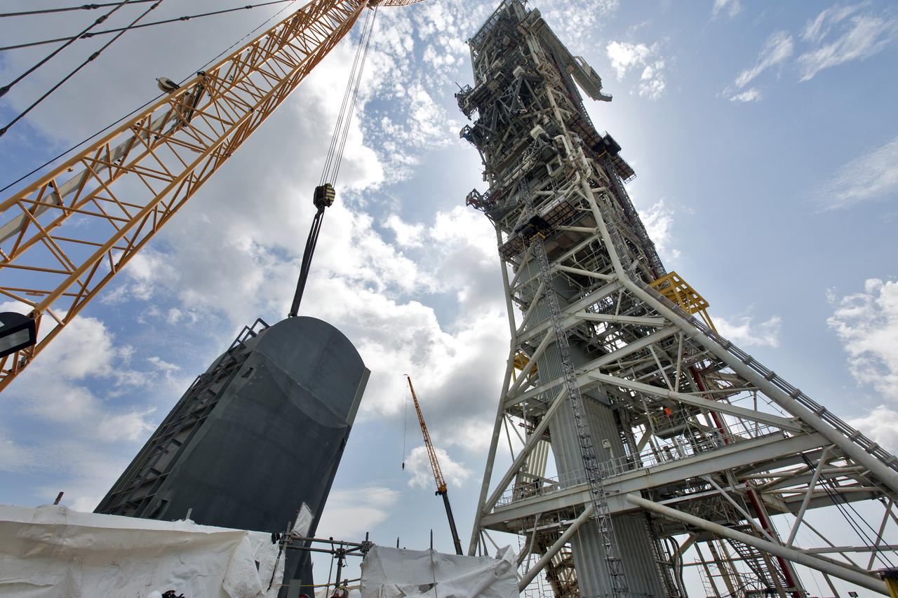
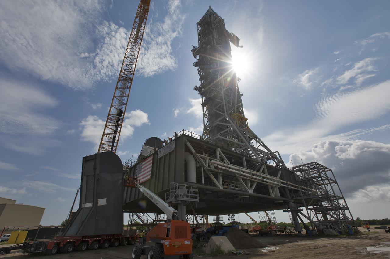
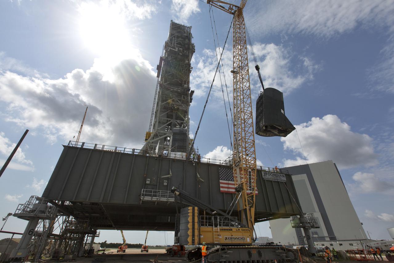
A crane is used to lower the first of two Tail Service Mast Umbilicals for installation on the 0-level deck of the mobile launcher on July 12, at NASA's Kennedy Space Center in Florida. The 35-foot-tall umbilical will connect to NASA's Space Launch System rocket core stage aft section and provide liquid oxygen and electrical cable connections to the core stage engine section to support propellant handling during prelaunch operations. The installation brings Exploration Ground Systems one step closer to supporting prelaunch operations for the agency's SLS rocket and Orion spacecraft on Exploration Mission-1 and deep space destinations.
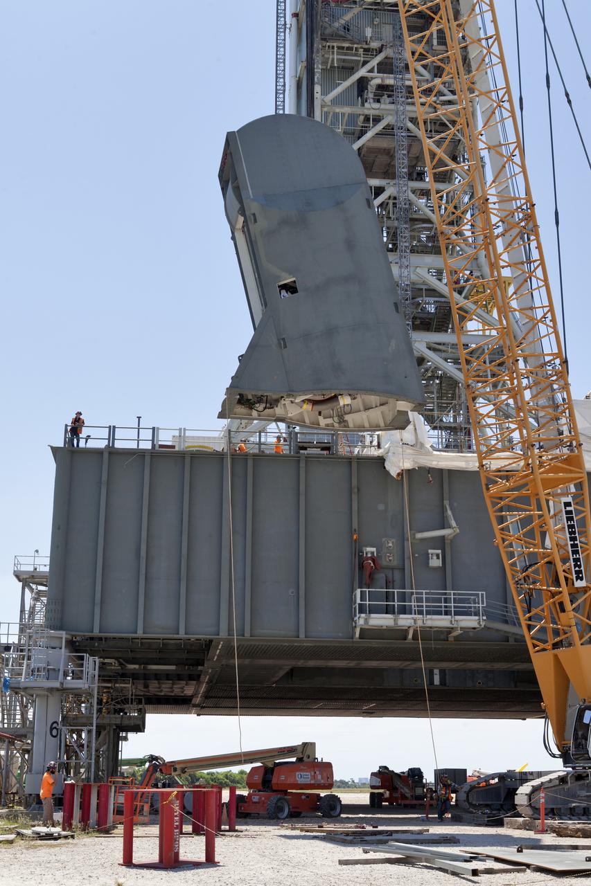
The second of two Tail Service Mast Umbilicals is lowered by crane for installation on the 0-level deck of the mobile launcher on July 27, at NASA's Kennedy Space Center in Florida. The 35-foot-tall umbilical will connect to NASA's Space Launch System (SLS) rocket core stage aft section and provide liquid hydrogen and electrical cable connections to the core stage engine section to support propellant handling during prelaunch operations. The installation brings Exploration Ground Systems one step closer to supporting prelaunch operations for the agency's SLS rocket and Orion spacecraft on Exploration Mission-1 and deep space destinations.

The first of two Tail Service Mast Umbilicals is lowered onto the 0-level deck of the mobile launcher on July 12, at NASA's Kennedy Space Center in Florida. The 35-foot-tall umbilical will connect to NASA's Space Launch System rocket core stage aft section and provide liquid oxygen and electrical cable connections to the core stage engine section to support propellant handling during prelaunch operations. The installation brings Exploration Ground Systems one step closer to supporting prelaunch operations for the agency's SLS rocket and Orion spacecraft on Exploration Mission-1 and deep space destinations.
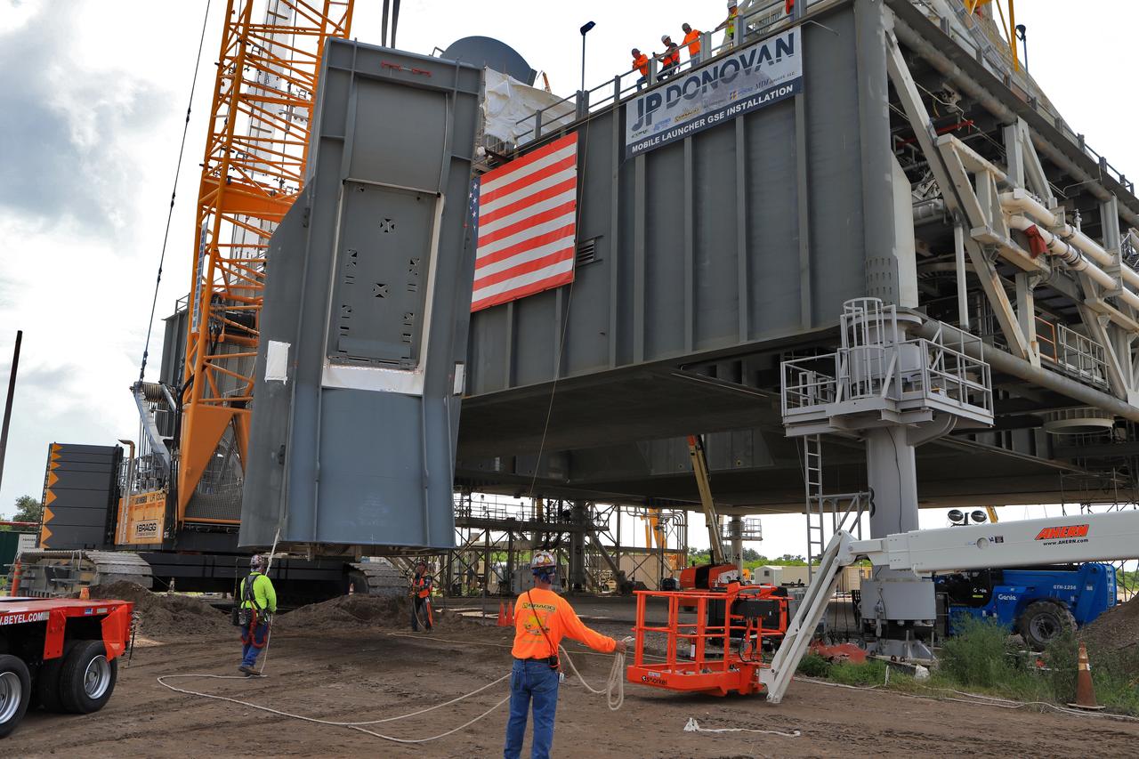
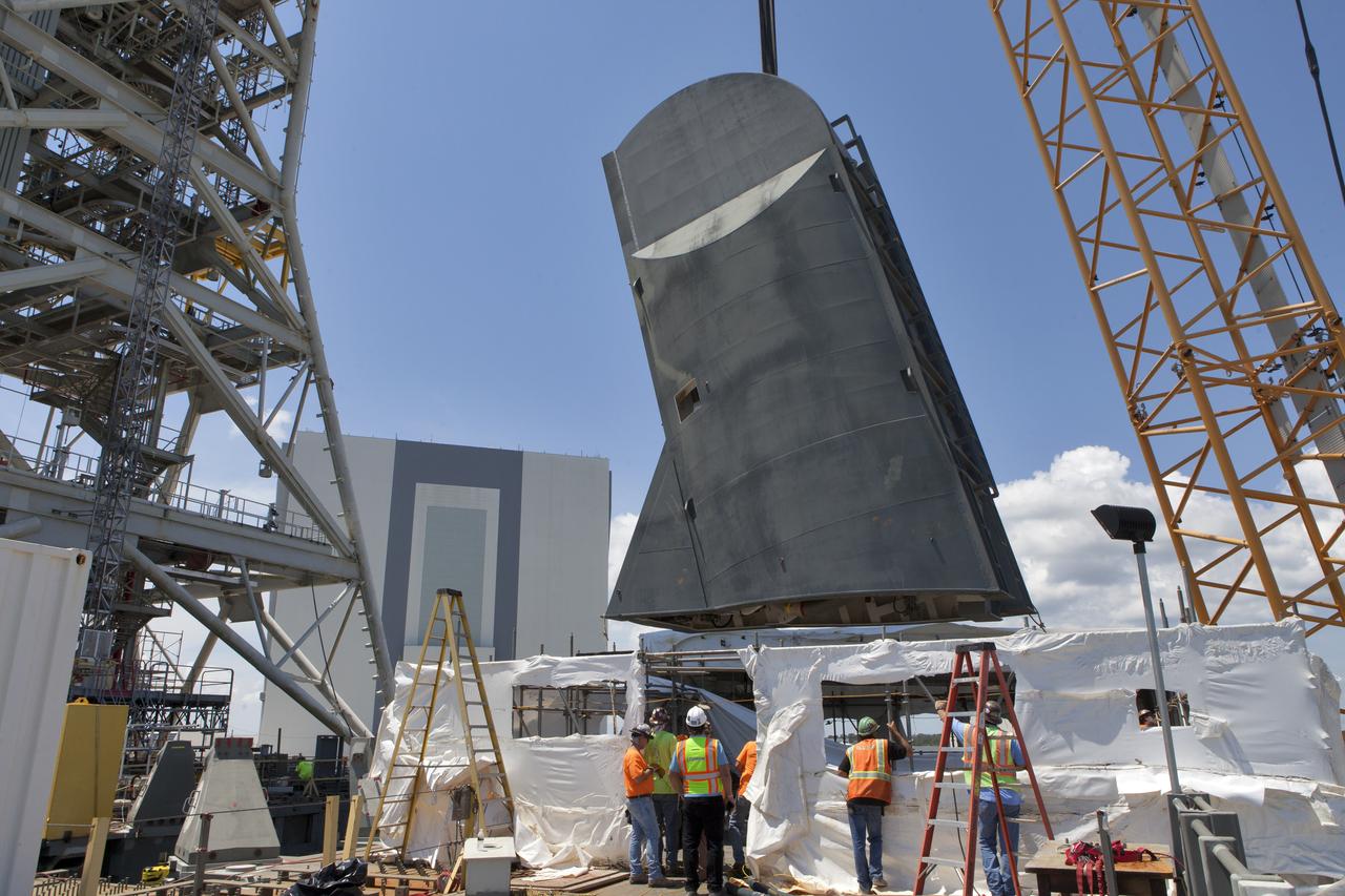
Preparations are underway to install the second of two Tail Service Mast Umbilicals on the 0-level deck of the mobile launcher on July 27, at NASA's Kennedy Space Center in Florida. The 35-foot-tall umbilical will connect to NASA's Space Launch System (SLS) rocket core stage aft section and provide liquid hydrogen and electrical cable connections to the core stage engine section to support propellant handling during prelaunch operations. The installation brings Exploration Ground Systems one step closer to supporting prelaunch operations for the agency's SLS rocket and Orion spacecraft on Exploration Mission-1 and deep space destinations.
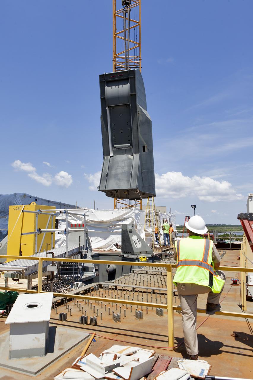
The second of two Tail Service Mast Umbilicals is lifted by crane for installation on the 0-level deck of the mobile launcher on July 27, at NASA's Kennedy Space Center in Florida. The 35-foot-tall umbilical will connect to NASA's Space Launch System (SLS) rocket core stage aft section and provide liquid hydrogen and electrical cable connections to the core stage engine section to support propellant handling during prelaunch operations. The installation brings Exploration Ground Systems one step closer to supporting prelaunch operations for the agency's SLS rocket and Orion spacecraft on Exploration Mission-1 and deep space destinations.
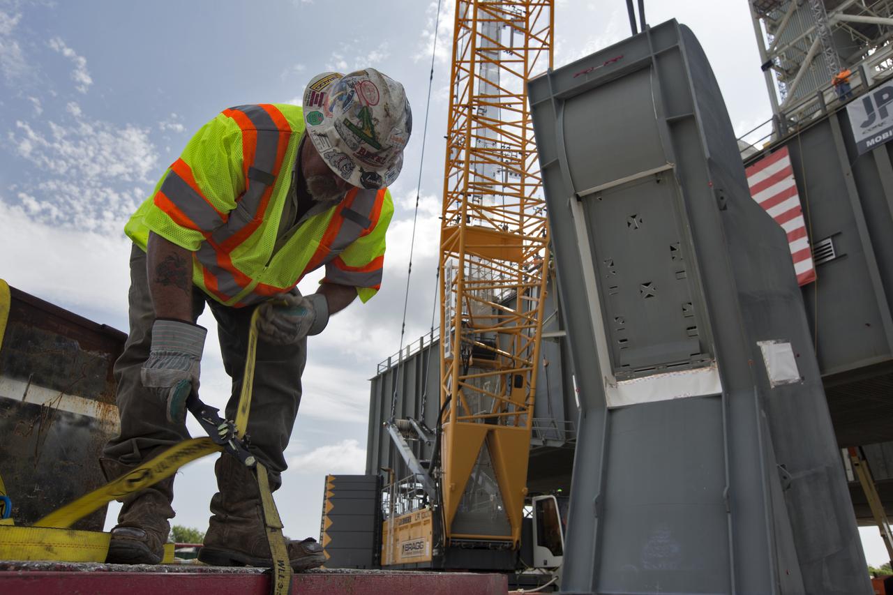
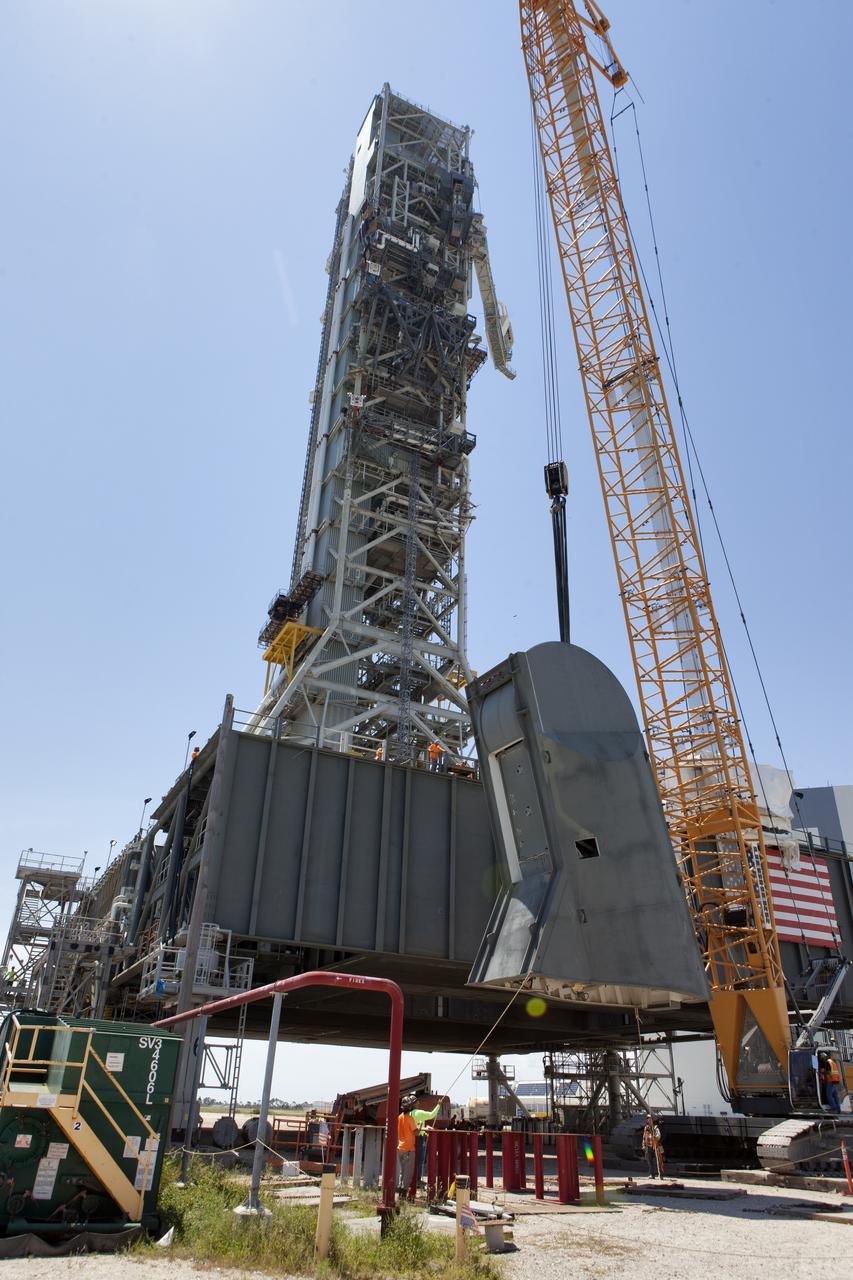
A JP Donovan construction worker makes preparations for lifting of the second of two Tail Service Mast Umbilicals for installation on the 0-level deck of the mobile launcher on July 27, at NASA's Kennedy Space Center in Florida. The 35-foot-tall umbilical will connect to NASA's Space Launch System (SLS) rocket core stage aft section and provide hydrogen and electrical cable connections to the core stage engine section to support propellant handling during prelaunch operations. The installation brings Exploration Ground Systems one step closer to supporting prelaunch operations for the agency's SLS rocket and Orion spacecraft on Exploration Mission-1 and deep space destinations.
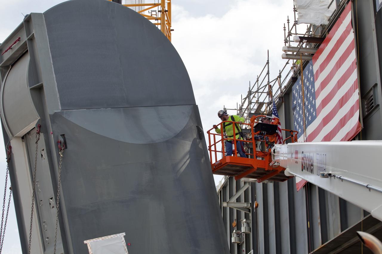
Preparations are underway to install the second of two Tail Service Mast Umbilicals on the 0-level deck of the mobile launcher on July 27, at NASA's Kennedy Space Center in Florida. The 35-foot-tall umbilical will connect to NASA's Space Launch System (SLS) rocket core stage aft section and provide liquid hydrogen and electrical cable connections to the core stage engine section to support propellant handling during prelaunch operations. The installation brings Exploration Ground Systems one step closer to supporting prelaunch operations for the agency's SLS rocket and Orion spacecraft on Exploration Mission-1 and deep space destinations.
The first of two Tail Service Mast Umbilicals is lifted up for installation on the 0-level deck of the mobile launcher on July 12, at NASA's Kennedy Space Center in Florida. The 35-foot-tall umbilical will connect to NASA's Space Launch System rocket core stage aft section and provide liquid oxygen and electrical cable connections to the core stage engine section to support propellant handling during prelaunch operations. The installation brings Exploration Ground Systems one step closer to supporting prelaunch operations for the agency's SLS rocket and Orion spacecraft on Exploration Mission-1 and deep space destinations.
A crane is used to lift up the first of two Tail Service Mast Umbilicals for installation on the 0-level deck of the mobile launcher on July 12, at NASA's Kennedy Space Center in Florida. The 35-foot-tall umbilical will connect to NASA's Space Launch System rocket core stage aft section and provide liquid oxygen and electrical cable connections to the core stage engine section to support propellant handling during prelaunch operations. The installation brings Exploration Ground Systems one step closer to supporting prelaunch operations for the agency's SLS rocket and Orion spacecraft on Exploration Mission-1 and deep space destinations.
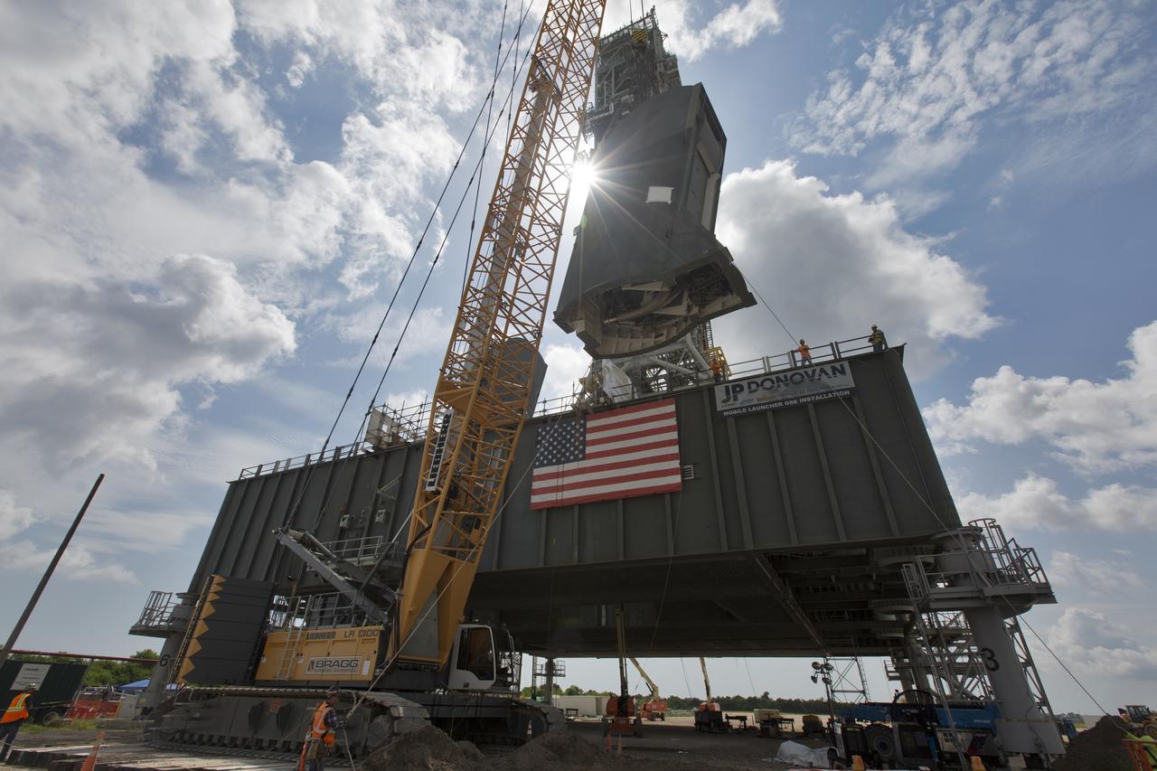
The second of two Tail Service Mast Umbilicals is lifted by crane for installation on the 0-level deck of the mobile launcher on July 27, at NASA's Kennedy Space Center in Florida. The 35-foot-tall umbilical will connect to NASA's Space Launch System (SLS) rocket core stage aft section and provide liquid hydrogen and electrical cable connections to the core stage engine section to support propellant handling during prelaunch operations. The installation brings Exploration Ground Systems one step closer to supporting prelaunch operations for the agency's SLS rocket and Orion spacecraft on Exploration Mission-1 and deep space destinations.
Construction workers with JP Donovan assist as a crane lifts the second of two Tail Service Mast Umbilicals up for installation on the 0-level deck of the mobile launcher on July 27, at NASA's Kennedy Space Center in Florida. The 35-foot-tall umbilical will connect to NASA's Space Launch System rocket core stage aft section and provide liquid hydrogen and electrical cable connections to the core stage engine section to support propellant handling during prelaunch operations. The installation brings Exploration Ground Systems one step closer to supporting prelaunch operations for the agency's SLS rocket and Orion spacecraft on Exploration Mission-1 and deep space destinations.
The first of two Tail Service Mast Umbilicals is lifted up for installation on the 0-level deck of the mobile launcher on July 12, at NASA's Kennedy Space Center in Florida. The 35-foot-tall umbilical will connect to NASA's Space Launch System rocket core stage aft section and provide liquid oxygen and electrical cable connections to the core stage engine section to support propellant handling during prelaunch operations. The installation brings Exploration Ground Systems one step closer to supporting prelaunch operations for the agency's SLS rocket and Orion spacecraft on Exploration Mission-1 and deep space destinations.
The second of two Tail Service Mast Umbilicals is lifted by crane for installation on the 0-level deck of the mobile launcher on July 27, at NASA's Kennedy Space Center in Florida. The 35-foot-tall umbilical will connect to NASA's Space Launch System (SLS) rocket core stage aft section and provide liquid hydrogen and electrical cable connections to the core stage engine section to support propellant handling during prelaunch operations. The installation brings Exploration Ground Systems one step closer to supporting prelaunch operations for the agency's SLS rocket and Orion spacecraft on Exploration Mission-1 and deep space destinations.
A crane is used to lift up the first of two Tail Service Mast Umbilicals for installation on the 0-level deck of the mobile launcher on July 12, at NASA's Kennedy Space Center in Florida. The 35-foot-tall umbilical will connect to NASA's Space Launch System rocket core stage aft section and provide liquid oxygen and electrical cable connections to the core stage engine section to support propellant handling during prelaunch operations. The installation brings Exploration Ground Systems one step closer to supporting prelaunch operations for the agency's SLS rocket and Orion spacecraft on Exploration Mission-1 and deep space destinations.
Construction workers with JP Donovan monitor operations as a crane is used to lower the first of two Tail Service Mast Umbilicals for installation on the 0-level deck of the mobile launcher on July 12, at NASA's Kennedy Space Center in Florida. The 35-foot-tall umbilical will connect to NASA's Space Launch System rocket core stage aft section and provide liquid oxygen and electrical cable connections to the core stage engine section to support propellant handling during prelaunch operations. The installation brings Exploration Ground Systems one step closer to supporting prelaunch operations for the agency's SLS rocket and Orion spacecraft on Exploration Mission-1 and deep space destinations.
A crane is used to lower the first of two Tail Service Mast Umbilicals for installation on the 0-level deck of the mobile launcher on July 12, at NASA's Kennedy Space Center in Florida. The 35-foot-tall umbilical will connect to NASA's Space Launch System rocket core stage aft section and provide liquid oxygen and electrical cable connections to the core stage engine section to support propellant handling during prelaunch operations. The installation brings Exploration Ground Systems one step closer to supporting prelaunch operations for the agency's SLS rocket and Orion spacecraft on Exploration Mission-1 and deep space destinations.
The first of two Tail Service Mast Umbilicals is lifted up for installation on the 0-level deck of the mobile launcher on July 12, at NASA's Kennedy Space Center in Florida. The 35-foot-tall umbilical will connect to NASA's Space Launch System rocket core stage aft section and provide liquid oxygen and electrical cable connections to the core stage engine section to support propellant handling during prelaunch operations. The installation brings Exploration Ground Systems one step closer to supporting prelaunch operations for the agency's SLS rocket and Orion spacecraft on Exploration Mission-1 and deep space destinations.
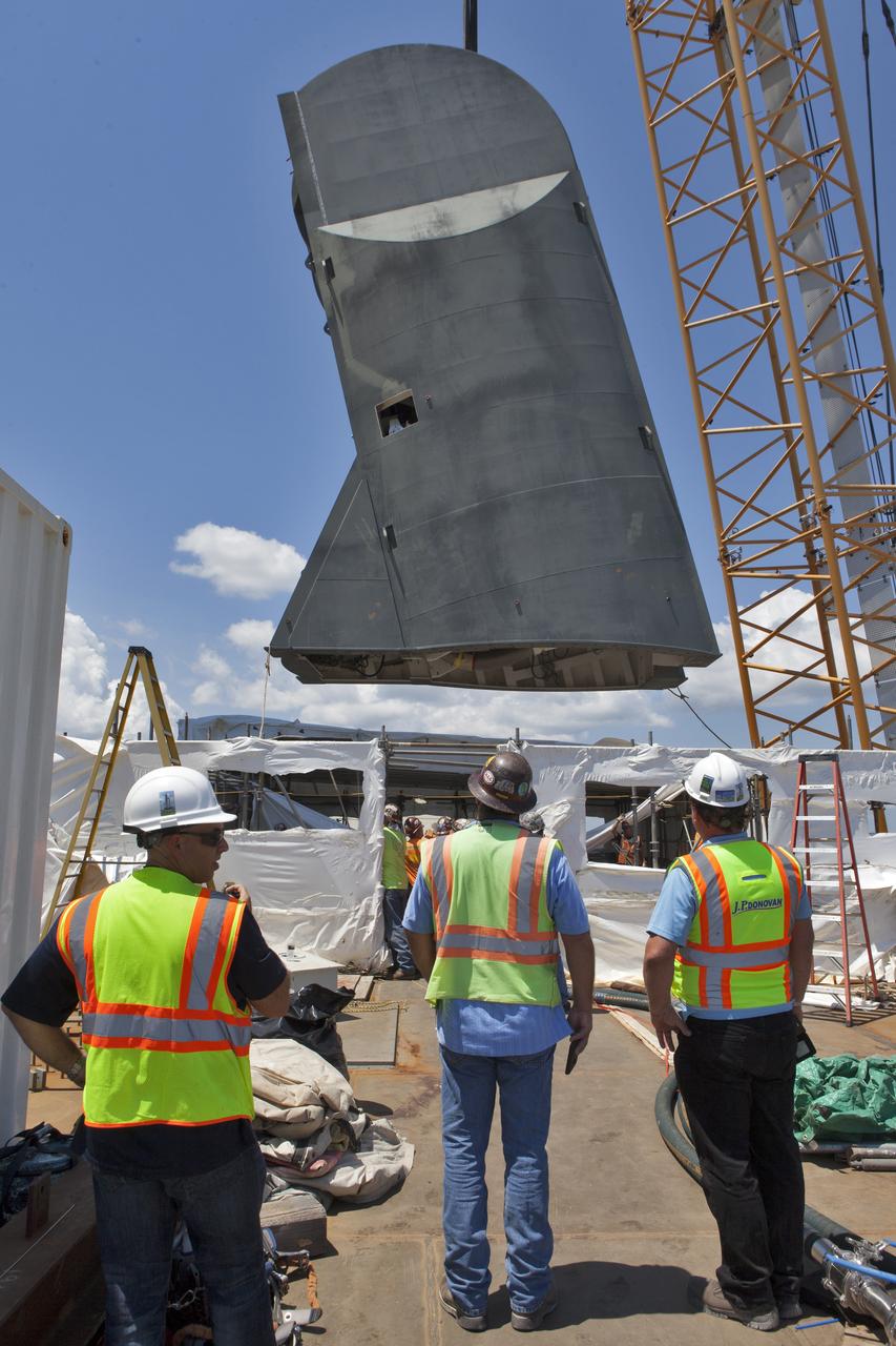
Construction workers with JP Donovan monitor operations as a crane is used to lower the first of two Tail Service Mast Umbilicals for installation on the 0-level deck of the mobile launcher on July 12, at NASA's Kennedy Space Center in Florida. The 35-foot-tall umbilical will connect to NASA's Space Launch System rocket core stage aft section and provide liquid oxygen and electrical cable connections to the core stage engine section to support propellant handling during prelaunch operations. The installation brings Exploration Ground Systems one step closer to supporting prelaunch operations for the agency's SLS rocket and Orion spacecraft on Exploration Mission-1 and deep space destinations.
The second of two Tail Service Mast Umbilicals is lifted by crane for installation on the 0-level deck of the mobile launcher on July 27, at NASA's Kennedy Space Center in Florida. The 35-foot-tall umbilical will connect to NASA's Space Launch System (SLS) rocket core stage aft section and provide liquid hydrogen and electrical cable connections to the core stage engine section to support propellant handling during prelaunch operations. The installation brings Exploration Ground Systems one step closer to supporting prelaunch operations for the agency's SLS rocket and Orion spacecraft on Exploration Mission-1 and deep space destinations.
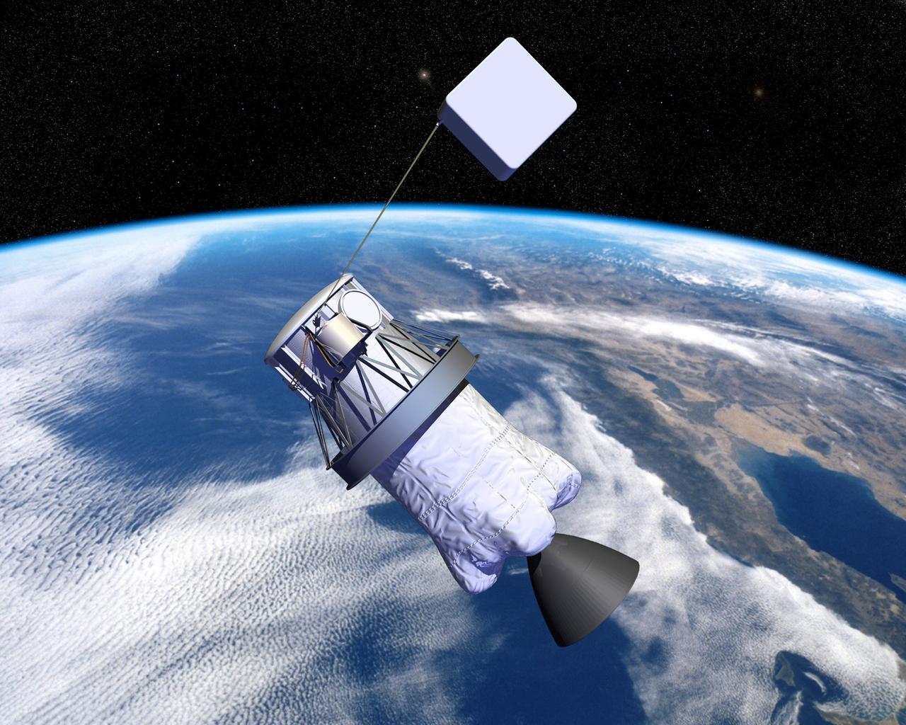
Pictured is an artist's concept of NASA's Propulsive Small Expendable Deployer System experiment (ProSEDS). ProSEDS will demonstrate the use of an electrodynamic tether, basically a long, thin wire, for propulsion. An electrodynamic tether uses the same principles as electric motors in toys, appliances and computer disk drives, and generators in automobiles and power plants. When electrical current is flowing through the tether, a magnetic field is produced that pushes against the magnetic field of the Earth. For ProSEDS, the current in the tether results by virtue of the voltage generated when the tether moves through the Earth's magnetic field at more than 17,000 mph. This approach can produce drag thrust generating useable power. Since electrodynamic tethers require no propellant, they could substantially reduce the weight of the spacecraft and provide a cost-effective method of reboosting spacecraft. The initial flight of ProSEDS is scheduled to fly aboard an Air Force Delta II rocket in summer of 2002. In orbit, ProSEDS will deploy from a Delta II second stage. It will be a 3.1-mile (5 kilometer) long, ultrathin base-wire tether cornected with a 6.2-mile (10 kilometer) long nonconducting tether. The ProSEDS experiment is managed by the Space Transportation Directorate at the Marshall Space Flight Center.
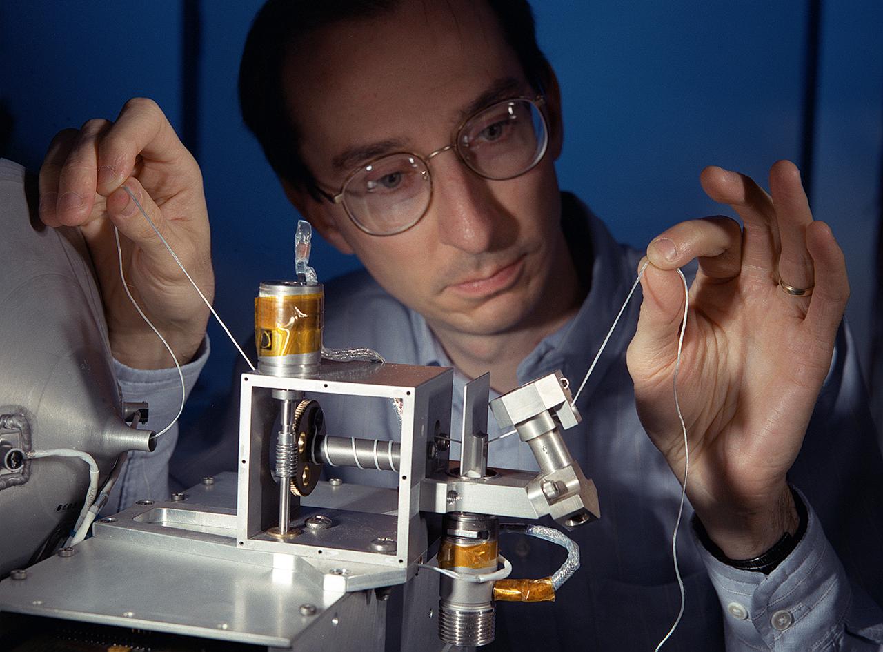
NASA's Propulsive Small Expendable Deployer System experiment (ProSEDS) will demonstrate the use of an electrodynamic tether, basically a long, thin wire, for propulsion. An electrodynamic tether uses the same principles as electric motors in toys, appliances and computer disk drives, and generators in automobiles and power plants. When electrical current is flowing through the tether, a magnetic field is produced that pushes against the magnetic field of the Earth. For ProSEDS, the current in the tether results by virtue of the voltage generated when the tether moves through the Earth's magnetic field at more than 17,000 mph. This approach can produce drag thrust generating useable power. Since electrodynamic tethers require no propellant, they could substantially reduce the weight of the spacecraft and provide a cost-effective method of reboosting spacecraft. The initial flight of ProSEDS is scheduled to fly aboard an Air Force Delta II rocket in the summer of 2002. In orbit, ProSEDS will deploy from a Delta II second stage. It will be a 3.1-mile (5 kilometer) long, ultrathin base-wire cornected with a 6.2-mile (10 kilometer) long nonconducting tether. This photograph shows Less Johnson, a scientist at MSFC inspecting the nonconducting part of a tether as it exits a deployer similar to the one to be used in the ProSEDS experiment. The ProSEDS experiment is managed by the Space Transportation Directorate at MSFC.
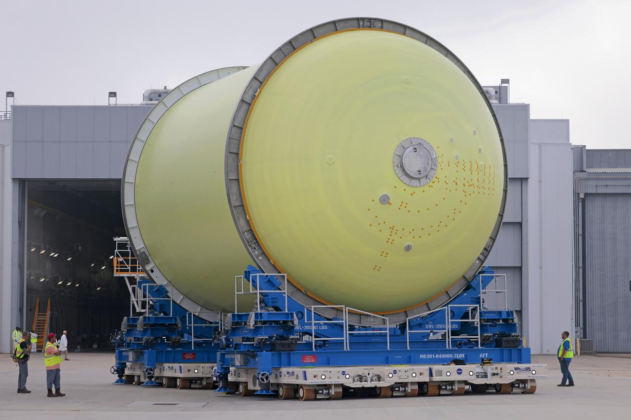
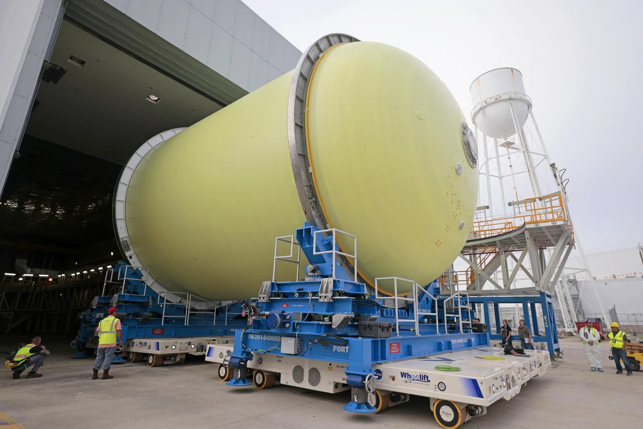
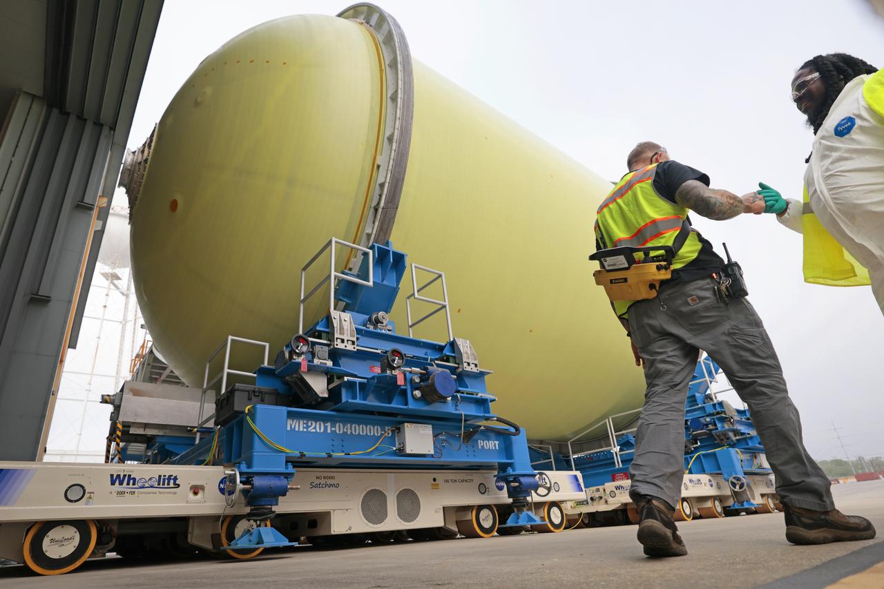
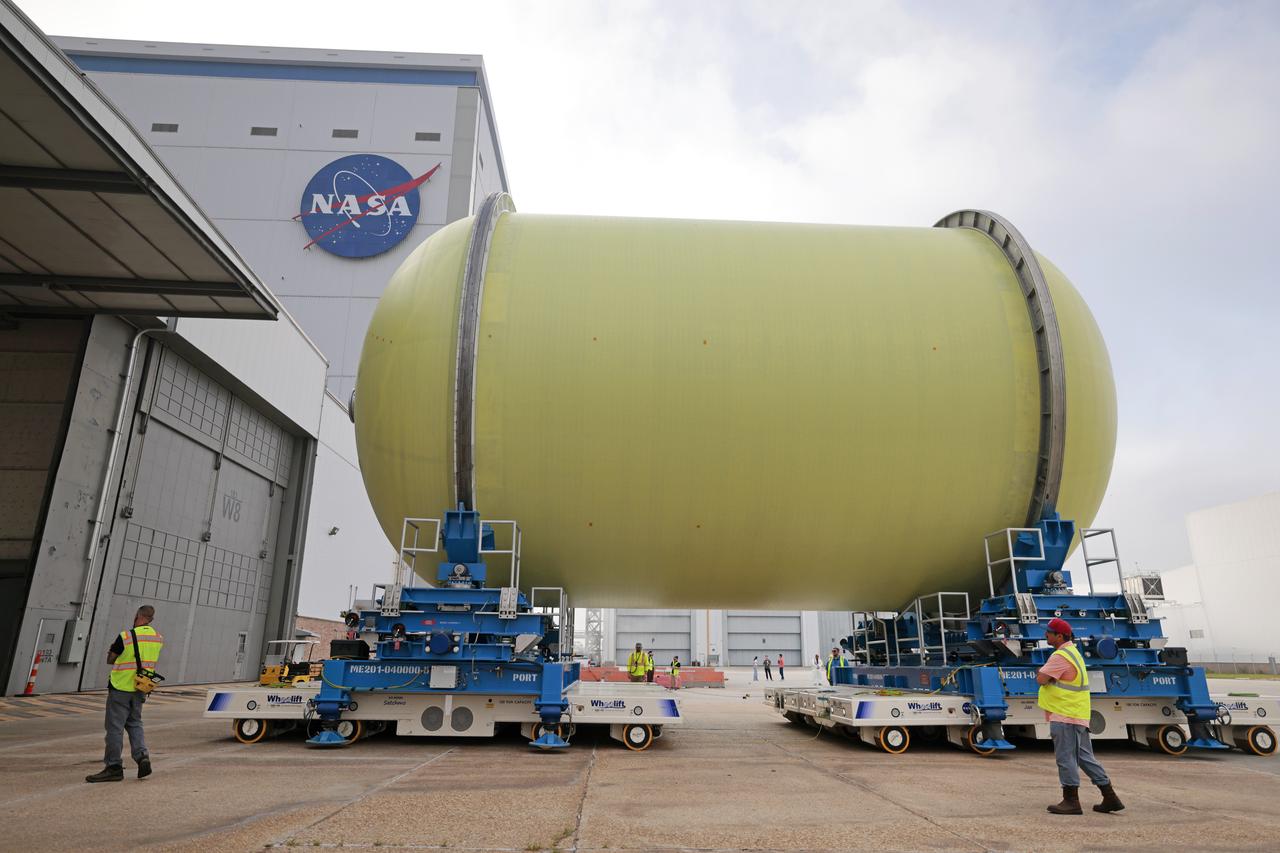
Move Crews at NASA’s Michoud Assembly Facility in New Orleans transport a liquid oxygen tank from a detached production building to the main 43-acre rocket factory on Mar. 26. Teams recently completed primer application on the tank, which will be used on the core stage of the agency’s SLS (Space Launch System) rocket for its Artemis III mission. The tank will now undergo electrical installations before moving on to the next phase of production. The propellant tank is one of five major elements that make up the 212-foot-tall rocket stage. The core stage, along with its four RS-25 engines, produce more than two million pounds of thrust to help launch NASA’s Orion spacecraft, astronauts, and supplies beyond Earth’s orbit and to the lunar surface for Artemis.
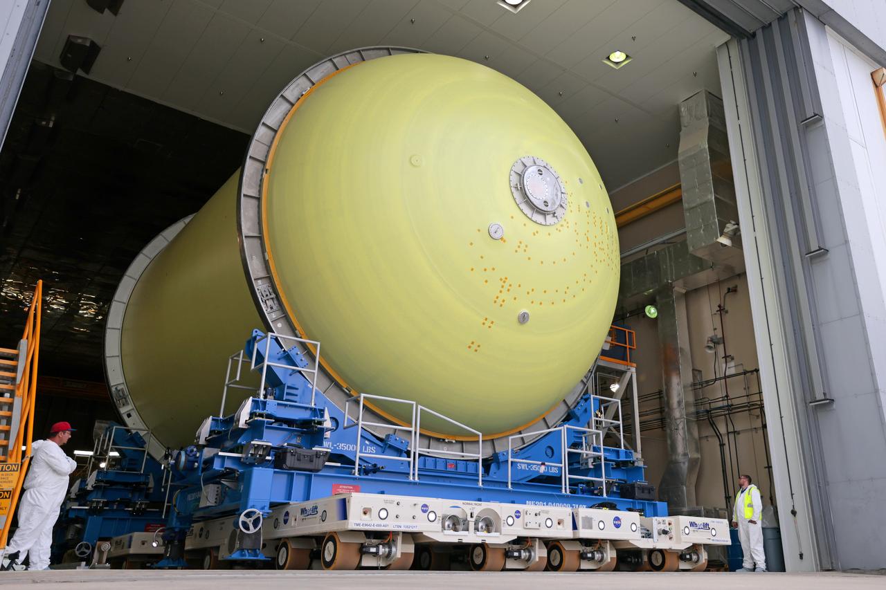
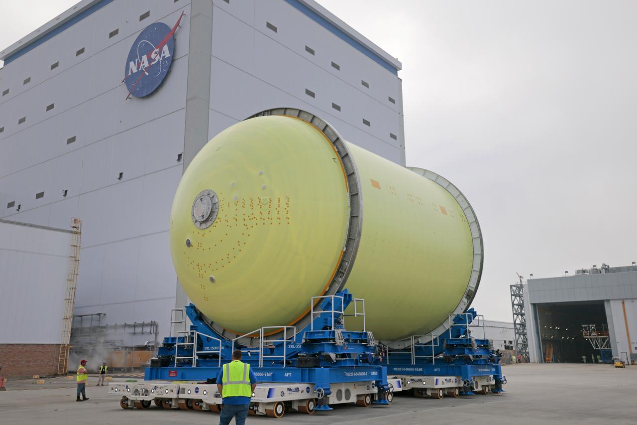
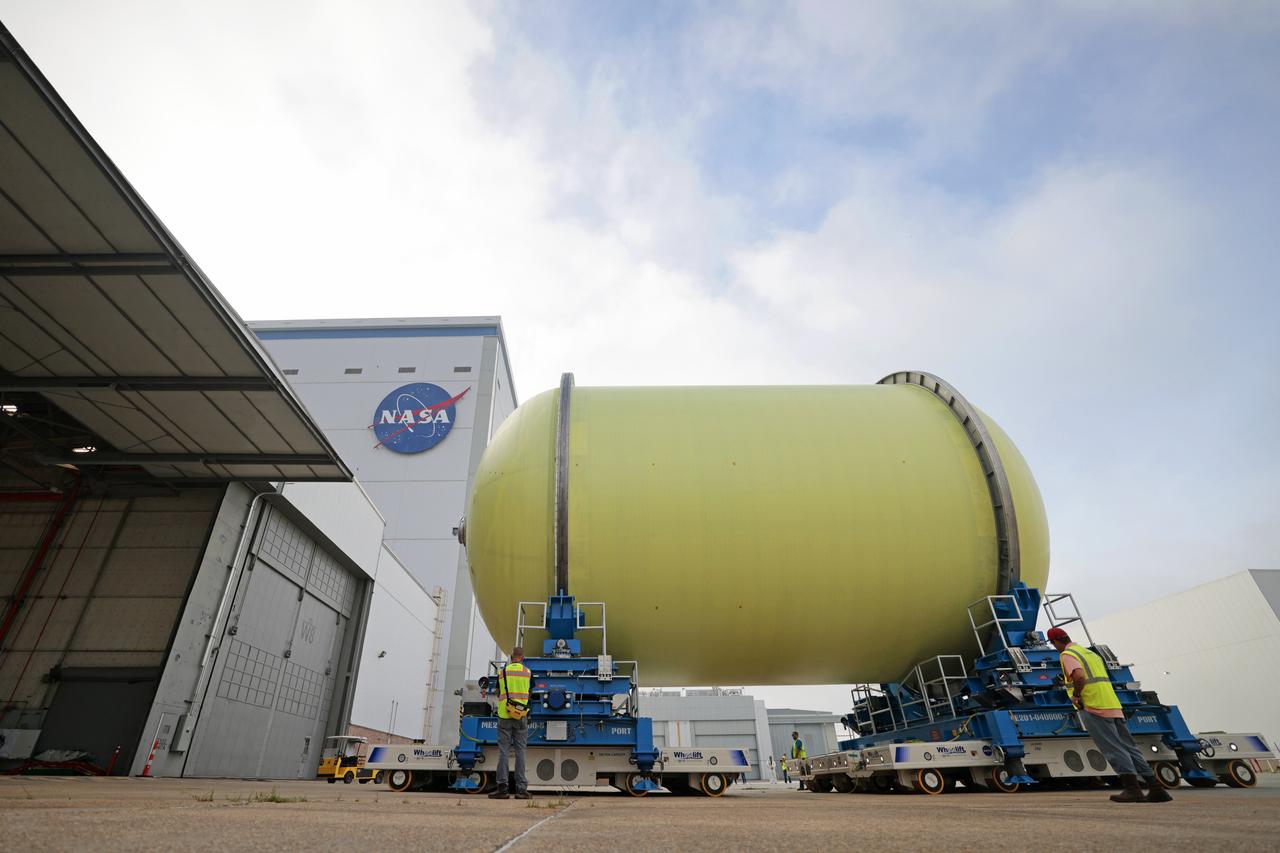
Move Crews at NASA’s Michoud Assembly Facility in New Orleans transport a liquid oxygen tank from a detached production building to the main 43-acre rocket factory on Mar. 26. Teams recently completed primer application on the tank, which will be used on the core stage of the agency’s SLS (Space Launch System) rocket for its Artemis III mission. The tank will now undergo electrical installations before moving on to the next phase of production. The propellant tank is one of five major elements that make up the 212-foot-tall rocket stage. The core stage, along with its four RS-25 engines, produce more than two million pounds of thrust to help launch NASA’s Orion spacecraft, astronauts, and supplies beyond Earth’s orbit and to the lunar surface for Artemis.
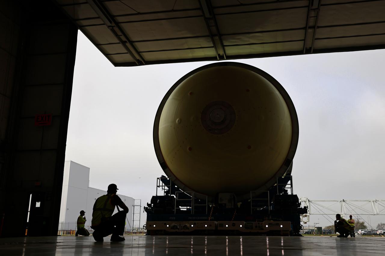
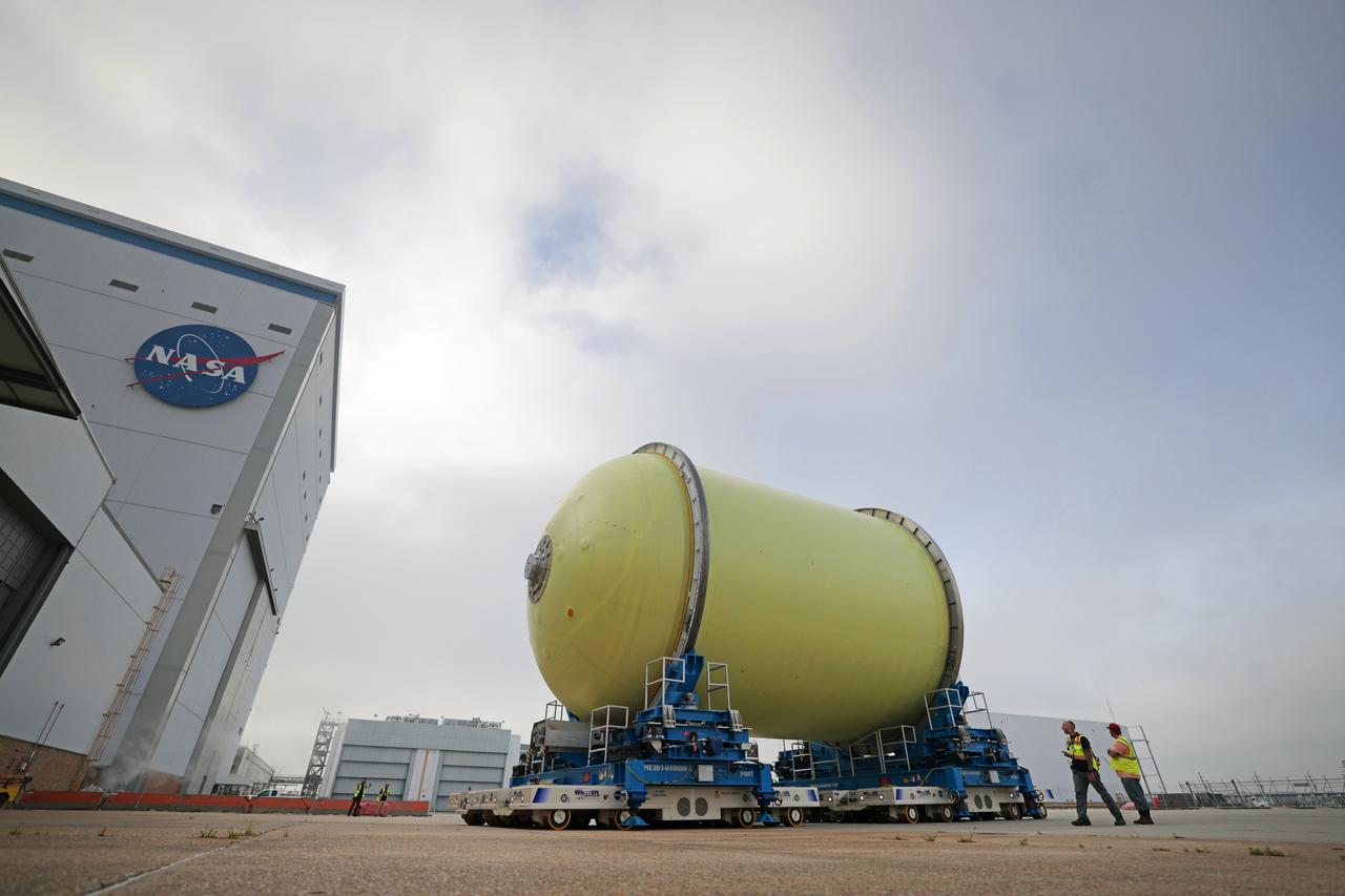
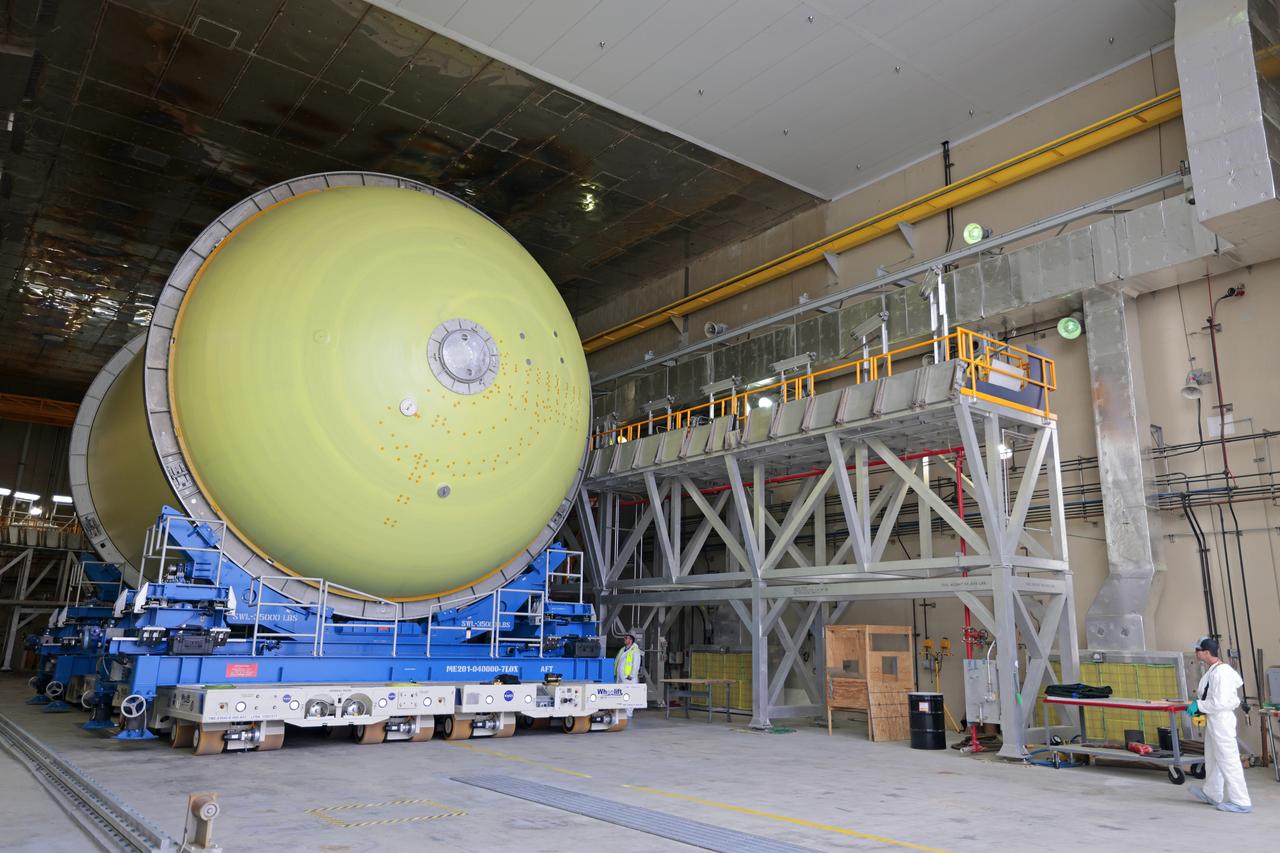
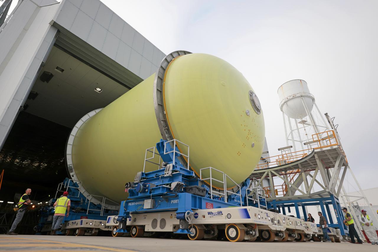
Move Crews at NASA’s Michoud Assembly Facility in New Orleans transport a liquid oxygen tank from a detached production building to the main 43-acre rocket factory on Mar. 26. Teams recently completed primer application on the tank, which will be used on the core stage of the agency’s SLS (Space Launch System) rocket for its Artemis III mission. The tank will now undergo electrical installations before moving on to the next phase of production. The propellant tank is one of five major elements that make up the 212-foot-tall rocket stage. The core stage, along with its four RS-25 engines, produce more than two million pounds of thrust to help launch NASA’s Orion spacecraft, astronauts, and supplies beyond Earth’s orbit and to the lunar surface for Artemis.
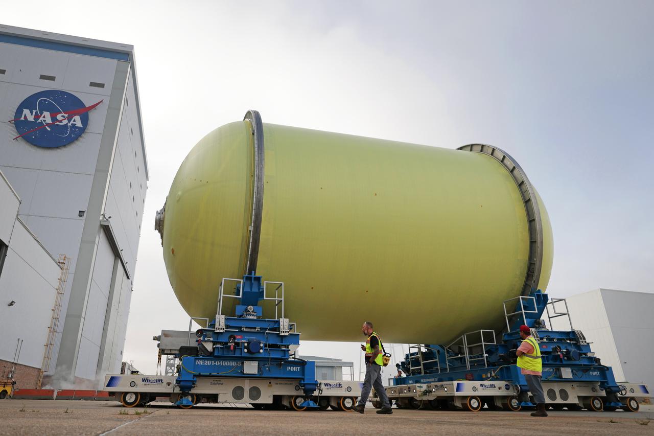
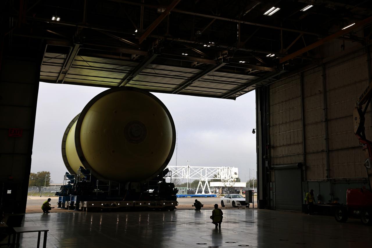
Move Crews at NASA’s Michoud Assembly Facility in New Orleans transport a liquid oxygen tank from a detached production building to the main 43-acre rocket factory on Mar. 26. Teams recently completed primer application on the tank, which will be used on the core stage of the agency’s SLS (Space Launch System) rocket for its Artemis III mission. The tank will now undergo electrical installations before moving on to the next phase of production. The propellant tank is one of five major elements that make up the 212-foot-tall rocket stage. The core stage, along with its four RS-25 engines, produce more than two million pounds of thrust to help launch NASA’s Orion spacecraft, astronauts, and supplies beyond Earth’s orbit and to the lunar surface for Artemis.
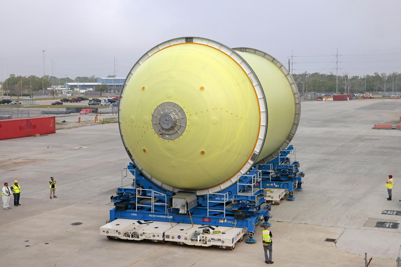
Move Crews at NASA’s Michoud Assembly Facility in New Orleans transport a liquid oxygen tank from a detached production building to the main 43-acre rocket factory on Mar. 26. Teams recently completed primer application on the tank, which will be used on the core stage of the agency’s SLS (Space Launch System) rocket for its Artemis III mission. The tank will now undergo electrical installations before moving on to the next phase of production. The propellant tank is one of five major elements that make up the 212-foot-tall rocket stage. The core stage, along with its four RS-25 engines, produce more than two million pounds of thrust to help launch NASA’s Orion spacecraft, astronauts, and supplies beyond Earth’s orbit and to the lunar surface for Artemis.
Move Crews at NASA’s Michoud Assembly Facility in New Orleans transport a liquid oxygen tank from a detached production building to the main 43-acre rocket factory on Mar. 26. Teams recently completed primer application on the tank, which will be used on the core stage of the agency’s SLS (Space Launch System) rocket for its Artemis III mission. The tank will now undergo electrical installations before moving on to the next phase of production. The propellant tank is one of five major elements that make up the 212-foot-tall rocket stage. The core stage, along with its four RS-25 engines, produce more than two million pounds of thrust to help launch NASA’s Orion spacecraft, astronauts, and supplies beyond Earth’s orbit and to the lunar surface for Artemis.
Move Crews at NASA’s Michoud Assembly Facility in New Orleans transport a liquid oxygen tank from a detached production building to the main 43-acre rocket factory on Mar. 26. Teams recently completed primer application on the tank, which will be used on the core stage of the agency’s SLS (Space Launch System) rocket for its Artemis III mission. The tank will now undergo electrical installations before moving on to the next phase of production. The propellant tank is one of five major elements that make up the 212-foot-tall rocket stage. The core stage, along with its four RS-25 engines, produce more than two million pounds of thrust to help launch NASA’s Orion spacecraft, astronauts, and supplies beyond Earth’s orbit and to the lunar surface for Artemis.
Move Crews at NASA’s Michoud Assembly Facility in New Orleans transport a liquid oxygen tank from a detached production building to the main 43-acre rocket factory on Mar. 26. Teams recently completed primer application on the tank, which will be used on the core stage of the agency’s SLS (Space Launch System) rocket for its Artemis III mission. The tank will now undergo electrical installations before moving on to the next phase of production. The propellant tank is one of five major elements that make up the 212-foot-tall rocket stage. The core stage, along with its four RS-25 engines, produce more than two million pounds of thrust to help launch NASA’s Orion spacecraft, astronauts, and supplies beyond Earth’s orbit and to the lunar surface for Artemis.
Move Crews at NASA’s Michoud Assembly Facility in New Orleans transport a liquid oxygen tank from a detached production building to the main 43-acre rocket factory on Mar. 26. Teams recently completed primer application on the tank, which will be used on the core stage of the agency’s SLS (Space Launch System) rocket for its Artemis III mission. The tank will now undergo electrical installations before moving on to the next phase of production. The propellant tank is one of five major elements that make up the 212-foot-tall rocket stage. The core stage, along with its four RS-25 engines, produce more than two million pounds of thrust to help launch NASA’s Orion spacecraft, astronauts, and supplies beyond Earth’s orbit and to the lunar surface for Artemis.
Move Crews at NASA’s Michoud Assembly Facility in New Orleans transport a liquid oxygen tank from a detached production building to the main 43-acre rocket factory on Mar. 26. Teams recently completed primer application on the tank, which will be used on the core stage of the agency’s SLS (Space Launch System) rocket for its Artemis III mission. The tank will now undergo electrical installations before moving on to the next phase of production. The propellant tank is one of five major elements that make up the 212-foot-tall rocket stage. The core stage, along with its four RS-25 engines, produce more than two million pounds of thrust to help launch NASA’s Orion spacecraft, astronauts, and supplies beyond Earth’s orbit and to the lunar surface for Artemis.
Move Crews at NASA’s Michoud Assembly Facility in New Orleans transport a liquid oxygen tank from a detached production building to the main 43-acre rocket factory on Mar. 26. Teams recently completed primer application on the tank, which will be used on the core stage of the agency’s SLS (Space Launch System) rocket for its Artemis III mission. The tank will now undergo electrical installations before moving on to the next phase of production. The propellant tank is one of five major elements that make up the 212-foot-tall rocket stage. The core stage, along with its four RS-25 engines, produce more than two million pounds of thrust to help launch NASA’s Orion spacecraft, astronauts, and supplies beyond Earth’s orbit and to the lunar surface for Artemis.
Move Crews at NASA’s Michoud Assembly Facility in New Orleans transport a liquid oxygen tank from a detached production building to the main 43-acre rocket factory on Mar. 26. Teams recently completed primer application on the tank, which will be used on the core stage of the agency’s SLS (Space Launch System) rocket for its Artemis III mission. The tank will now undergo electrical installations before moving on to the next phase of production. The propellant tank is one of five major elements that make up the 212-foot-tall rocket stage. The core stage, along with its four RS-25 engines, produce more than two million pounds of thrust to help launch NASA’s Orion spacecraft, astronauts, and supplies beyond Earth’s orbit and to the lunar surface for Artemis.

Move Crews at NASA’s Michoud Assembly Facility in New Orleans transport a liquid oxygen tank from a detached production building to the main 43-acre rocket factory on Mar. 26. Teams recently completed primer application on the tank, which will be used on the core stage of the agency’s SLS (Space Launch System) rocket for its Artemis III mission. The tank will now undergo electrical installations before moving on to the next phase of production. The propellant tank is one of five major elements that make up the 212-foot-tall rocket stage. The core stage, along with its four RS-25 engines, produce more than two million pounds of thrust to help launch NASA’s Orion spacecraft, astronauts, and supplies beyond Earth’s orbit and to the lunar surface for Artemis.
Move Crews at NASA’s Michoud Assembly Facility in New Orleans transport a liquid oxygen tank from a detached production building to the main 43-acre rocket factory on Mar. 26. Teams recently completed primer application on the tank, which will be used on the core stage of the agency’s SLS (Space Launch System) rocket for its Artemis III mission. The tank will now undergo electrical installations before moving on to the next phase of production. The propellant tank is one of five major elements that make up the 212-foot-tall rocket stage. The core stage, along with its four RS-25 engines, produce more than two million pounds of thrust to help launch NASA’s Orion spacecraft, astronauts, and supplies beyond Earth’s orbit and to the lunar surface for Artemis.
Move Crews at NASA’s Michoud Assembly Facility in New Orleans transport a liquid oxygen tank from a detached production building to the main 43-acre rocket factory on Mar. 26. Teams recently completed primer application on the tank, which will be used on the core stage of the agency’s SLS (Space Launch System) rocket for its Artemis III mission. The tank will now undergo electrical installations before moving on to the next phase of production. The propellant tank is one of five major elements that make up the 212-foot-tall rocket stage. The core stage, along with its four RS-25 engines, produce more than two million pounds of thrust to help launch NASA’s Orion spacecraft, astronauts, and supplies beyond Earth’s orbit and to the lunar surface for Artemis.
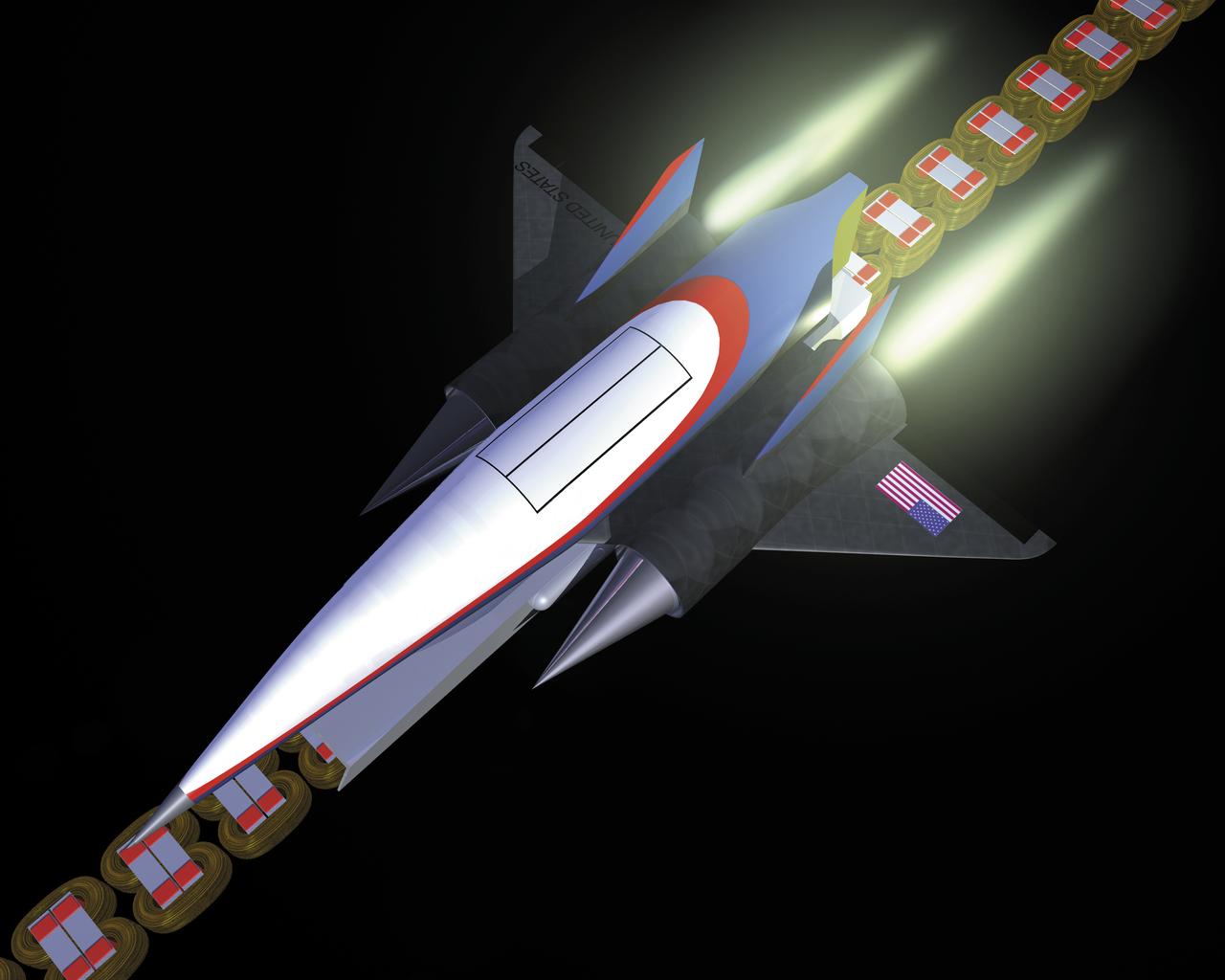
This artist’s concept depicts a Magnetic Launch Assist vehicle clearing the track and shifting to rocket engines for launch into orbit. The system, formerly referred as the Magnetic Levitation (MagLev) system, is a launch system developed and tested by Engineers at the Marshall Space Flight Center (MSFC) that could levitate and accelerate a launch vehicle along a track at high speeds before it leaves the ground. Using an off-board electric energy source and magnetic fields, a Magnetic Launch Assist system would drive a spacecraft along a horizontal track until it reaches desired speeds. The system is similar to high-speed trains and roller coasters that use high-strength magnets to lift and propel a vehicle a couple of inches above a guideway. A full-scale, operational track would be about 1.5-miles long, capable of accelerating a vehicle to 600 mph in 9.5 seconds, and the vehicle would then shift to rocket engines for launch into orbit. The major advantages of launch assist for NASA launch vehicles is that it reduces the weight of the take-off, the landing gear, the wing size, and less propellant resulting in significant cost savings. The US Navy and the British MOD (Ministry of Defense) are planning to use magnetic launch assist for their next generation aircraft carriers as the aircraft launch system. The US Army is considering using this technology for launching target drones for anti-aircraft training.
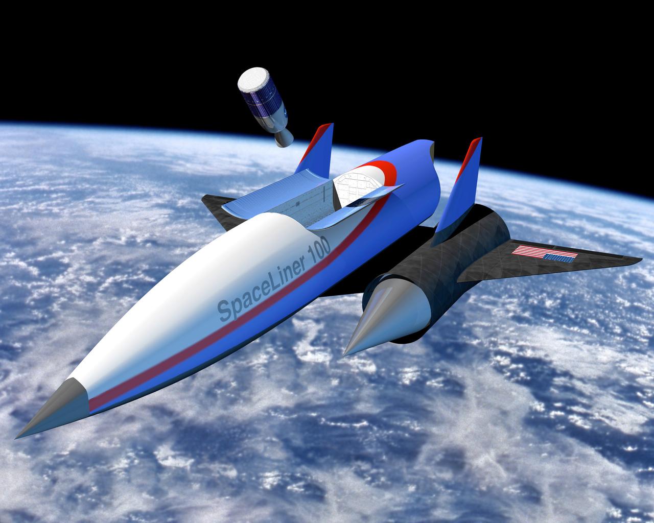
This artist’s concept depicts a Magnetic Launch Assist vehicle in orbit. Formerly referred to as the Magnetic Levitation (Maglev) system, the Magnetic Launch Assist system is a launch system developed and tested by engineers at the Marshall Space Flight Center (MSFC) that could levitate and accelerate a launch vehicle along a track at high speeds before it leaves the ground. Using electricity and magnetic fields, a Magnetic Launch Assist system would drive a spacecraft along a horizontal track until it reaches desired speeds. The system is similar to high-speed trains and roller coasters that use high-strength magnets to lift and propel a vehicle a couple of inches above a guideway. A full-scale, operational track would be about 1.5-miles long, capable of accelerating a vehicle to 600 mph in 9.5 seconds, and the vehicle would then shift to rocket engines for launch into orbit. The major advantages of launch assist for NASA launch vehicles is that it reduces the weight of the take-off, the landing gear, the wing size, and less propellant resulting in significant cost savings. The US Navy and the British MOD (Ministry of Defense) are planning to use magnetic launch assist for their next generation aircraft carriers as the aircraft launch system. The US Army is considering using this technology for launching target drones for anti-aircraft training.
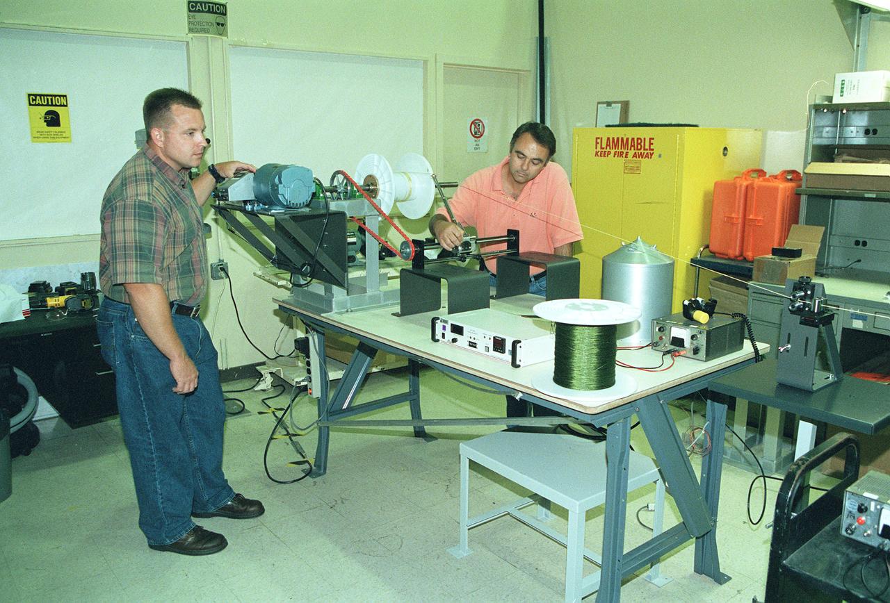
This photograph shows two Marshall Space Flight Center (MSFC) engineers, Mark Vaccaro (left) and Ken Welzyn, testing electrodynamic tethers in the MSFC Tether Winding and Spark Testing Facility. For 4 years, MSFC and industry partners have been developing the Propulsive Small Expendable Deployer System experiment, called ProSEDS. ProSEDS will test electrodynamic tether propulsion technology. Electrodynamic tethers are long, thin wires that collect electrical current when passing through a magnetic field. The tether works as a thruster as a magnetic field exerts a force on a current-carrying wire. Since electrodynamic tethers require no propellant, they could substantially reduce the weight of the spacecraft and provide a cost-effective method of reboosting spacecraft. The initial flight of ProSEDS is scheduled to fly aboard an Air Force Delta II rocket in the summer of 2002. In orbit, ProSEDS will deploy from a Delta II second stage. It will be a 3.1-mile (5 kilometer) long, ultrathin base-wire tether cornected with a 6.2-mile (10 kilometer) long non-conducting tether. This photograph shows Less Johnson, a scientist at MSFC, inspecting the nonconducting part of a tether as it exits a deployer similar to the one to be used in the ProSEDS experiment. The ProSEDS experiment is managed by the Space Transportation Directorate at MSFC.
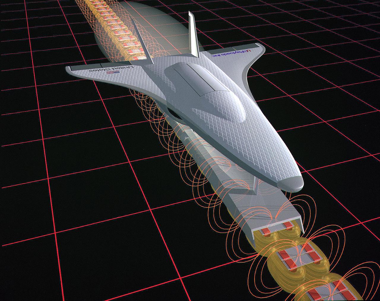
This illustration is an artist’s concept of a Magnetic Launch Assist System, formerly referred as the Magnetic Levitation (Maglev) system, for space launch. Overcoming the grip of Earth’s gravity is a supreme challenge for engineers who design rockets that leave the planet. Engineers at the Marshall Space Flight Center have developed and tested Magnetic Launch Assist System technologies that could levitate and accelerate a launch vehicle along a track at high speeds before it leaves the ground. Using electricity and magnetic fields, a Magnetic Launch Assist system would drive a spacecraft along a horizontal track until it reaches desired speeds. A full-scale, operational track would be about 1.5-miles long and capable of accelerating a vehicle to 600 mph in 9.5 seconds. The major advantages of launch assist for NASA launch vehicles is that it reduces the weight of the take-off, landing gear and the wing size, as well as the elimination of propellant weight resulting in significant cost savings. The US Navy and the British MOD (Ministry of Defense) are planning to use magnetic launch assist for their next generation aircraft carriers as the aircraft launch system. The US Army is considering using this technology for launching target drones for anti-aircraft training.