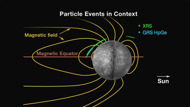
Locations of Energetic Electron Events
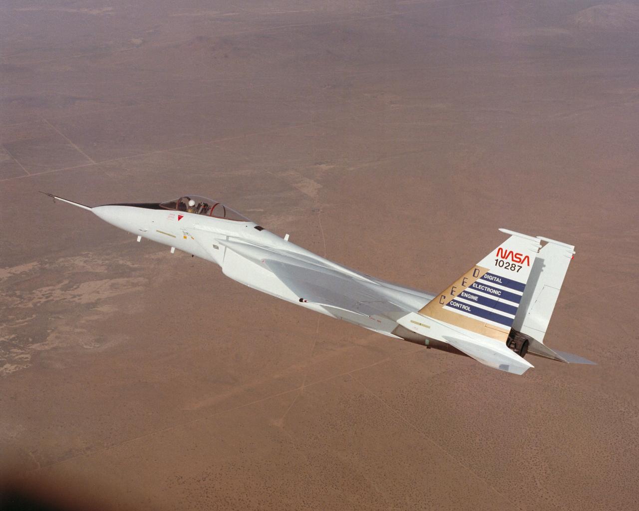
Digital Electronic Engine Control F-15A #287 in flight.
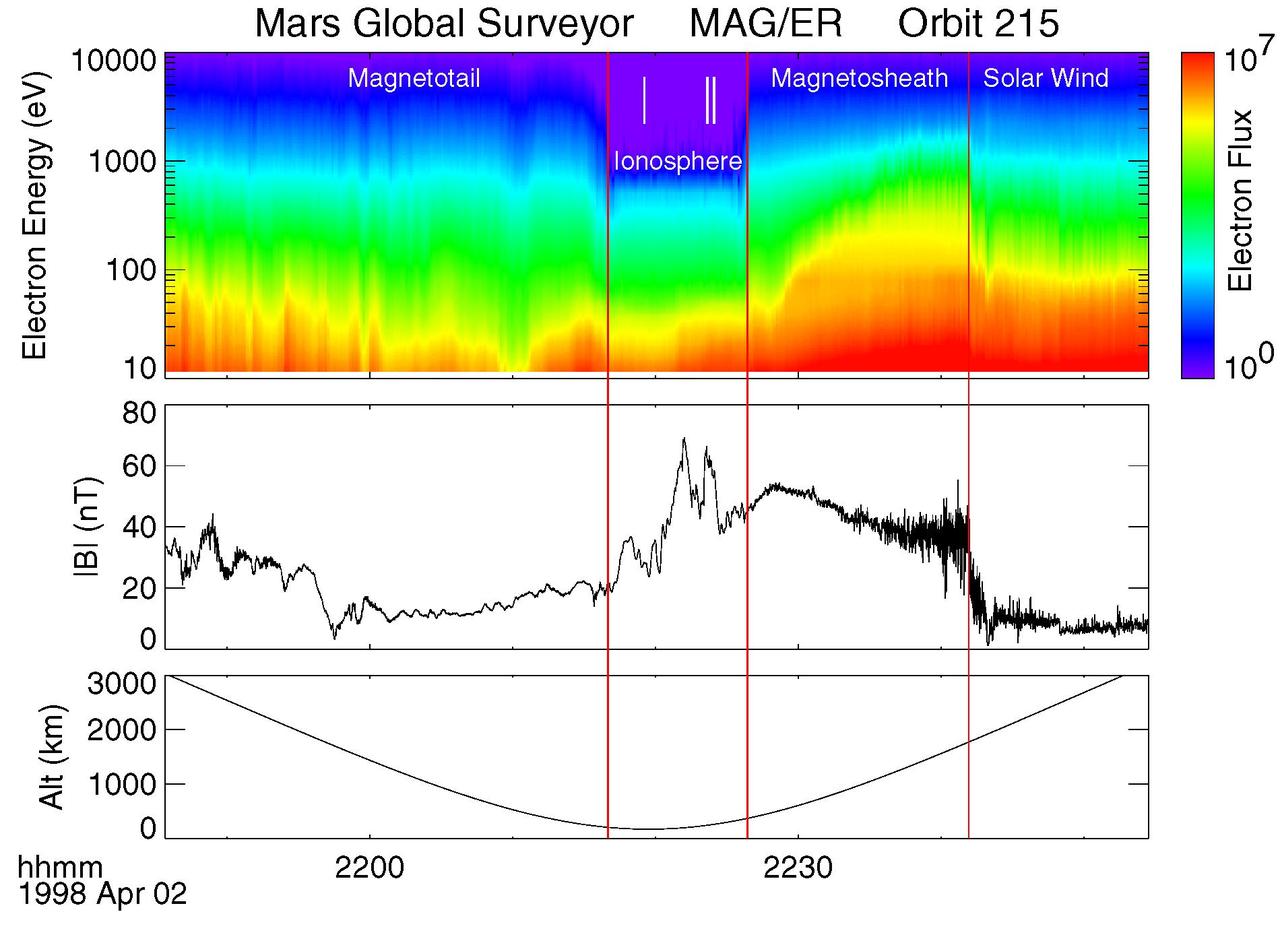
Electron and Magnetic Field Observations MAG/ER
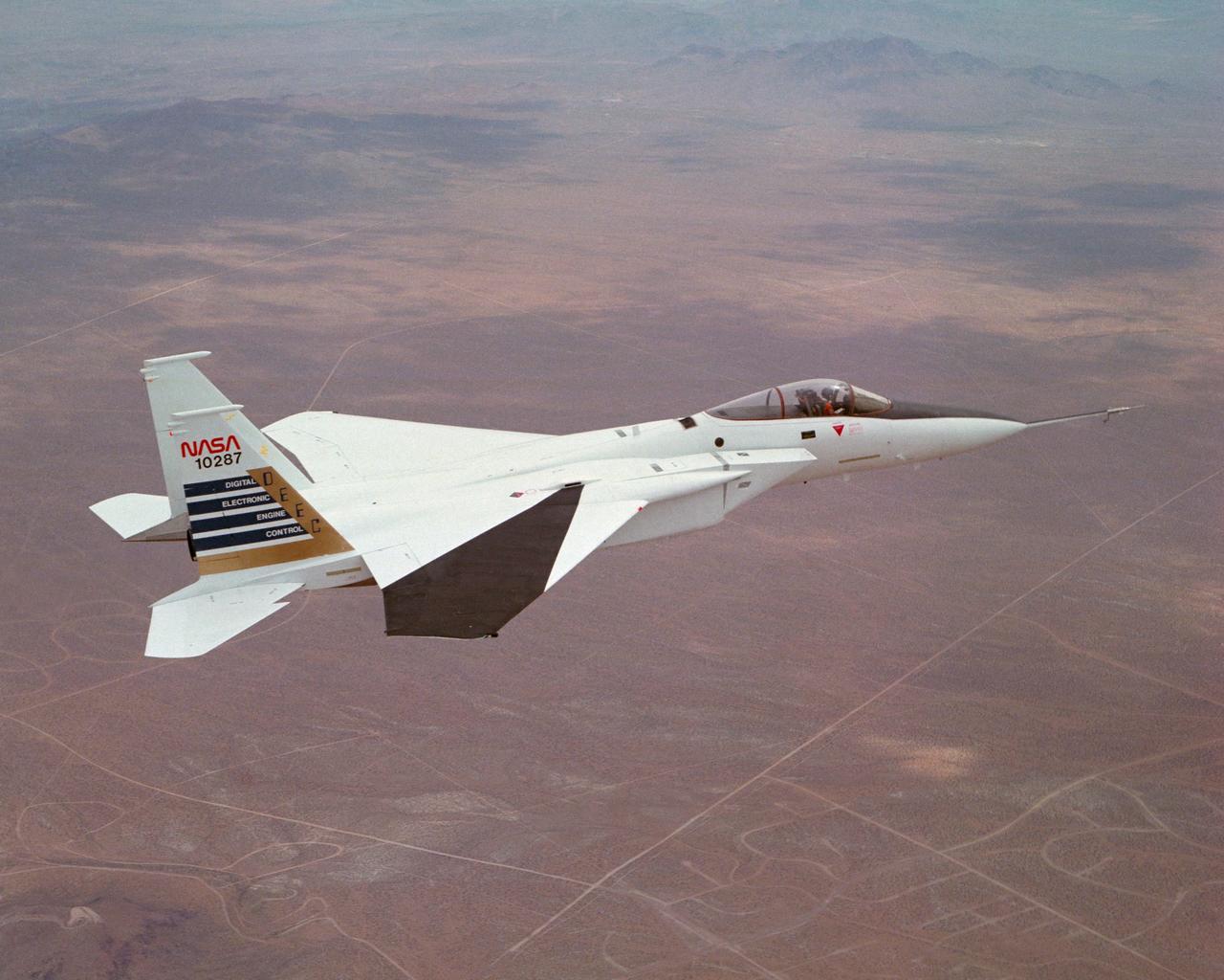
Digital Electronic Engine Control F-15A #287 in flight over California City. Note wing deflection measurement system on right wing.
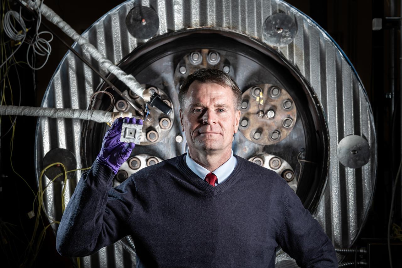
Phil Neudeck- Can Take the Heat When it comes to the heat of extreme environments like Venus, electronics can get fried within a few minutes of arrival. But NASA Researcher Phil Neudeck and his team have developed extremely durable silicon carbide semiconductor integrated circuits to survive those harsh conditions. After successfully testing the electronics in our high-pressure, high-temperature extreme environments chamber, there is now a path forward for Venus landers to survive and operate scientific experiments on the planet’s surface for longer durations.
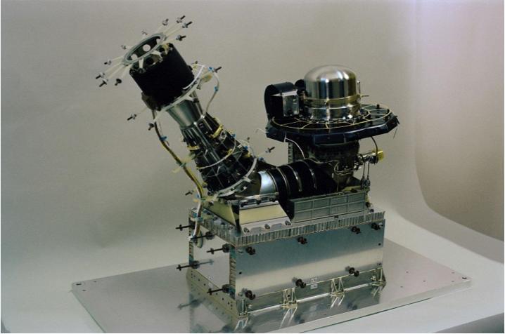
NASA has provided part of the electronics package for an instrument called the Double Focusing Mass Spectrometer, which is part of the Swiss-built Rosetta Orbiter Spectrometer for Ion and Neutral Analysis ROSINA instrument.
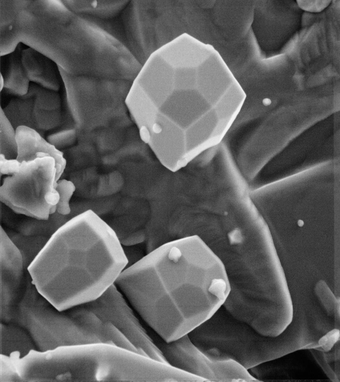
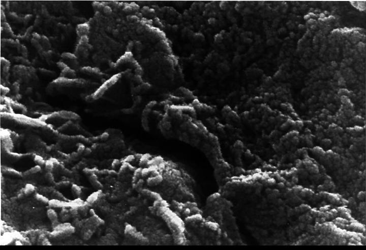
A scanning electron microscope photograph of iron crystals which grow in a small vug or cavity in a recrystallized breccia (fragmented rock) from the Apollo 15 Hadley-Apennino lunar landing site. The largest crystal is three microns across. Perfectly developed crystals such as these indicate slow formation from a hot vapor as the rock was cooling. The crystals are resting on an interlocking lattice of pyroxene (calsium-magnesium-iron silicate).
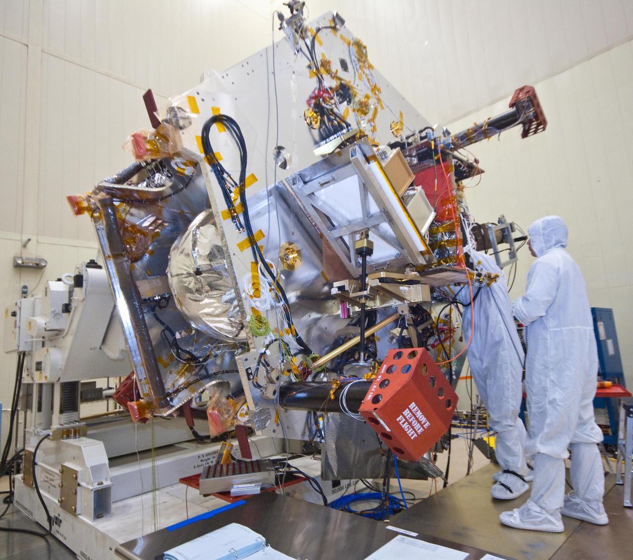
Technicians install components that will aid with guidance, navigation and control of NASA Juno spacecraft. Like most of Juno sensitive electronics, these components are situated within the spacecraft titanium radiation vault.
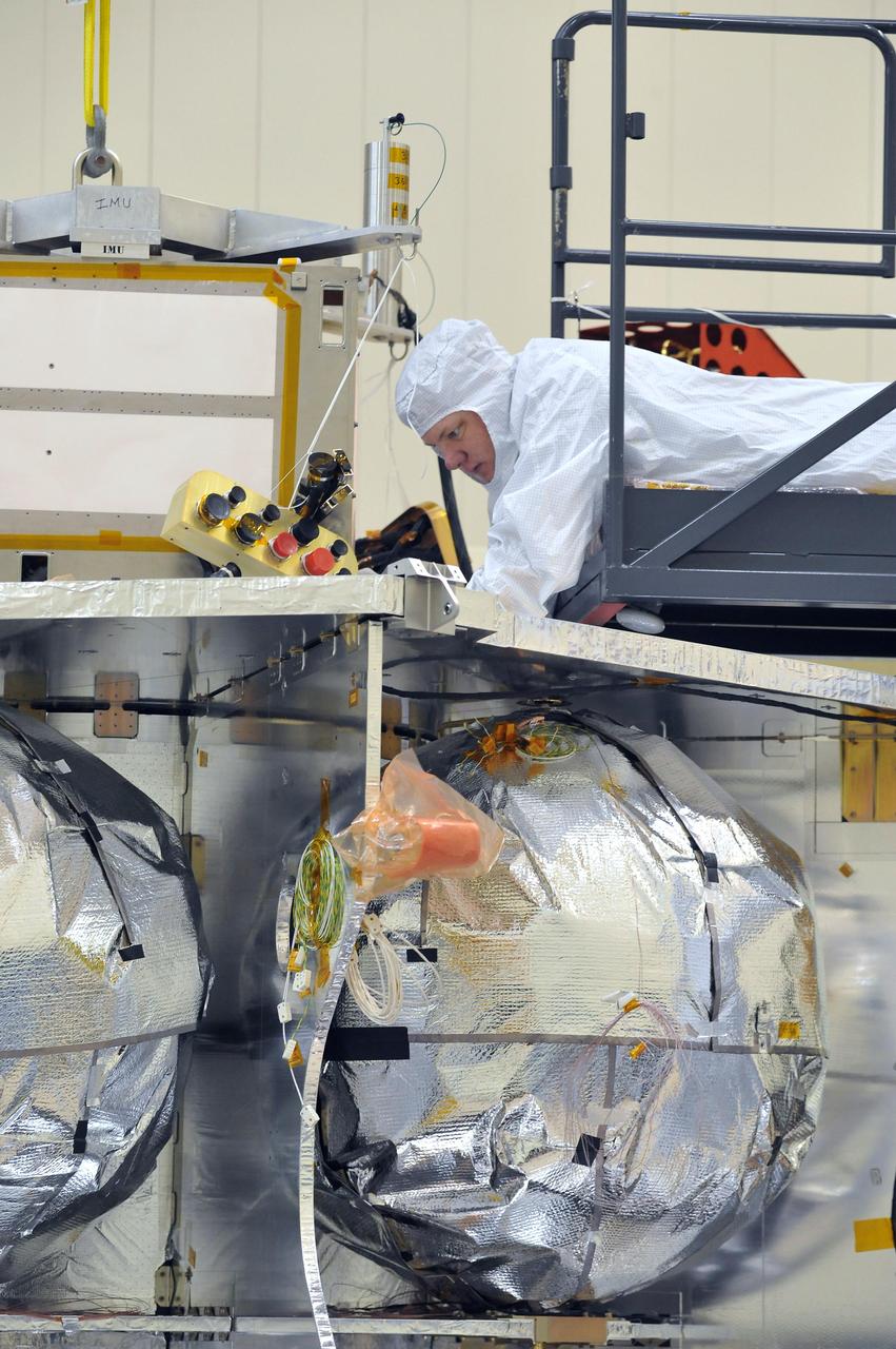
Technicians installed the special radiation vault for NASA Juno spacecraft on the propulsion module. The radiation vault has titanium walls to protect the spacecraft electronic brain and heart from Jupiter harsh radiation environment.
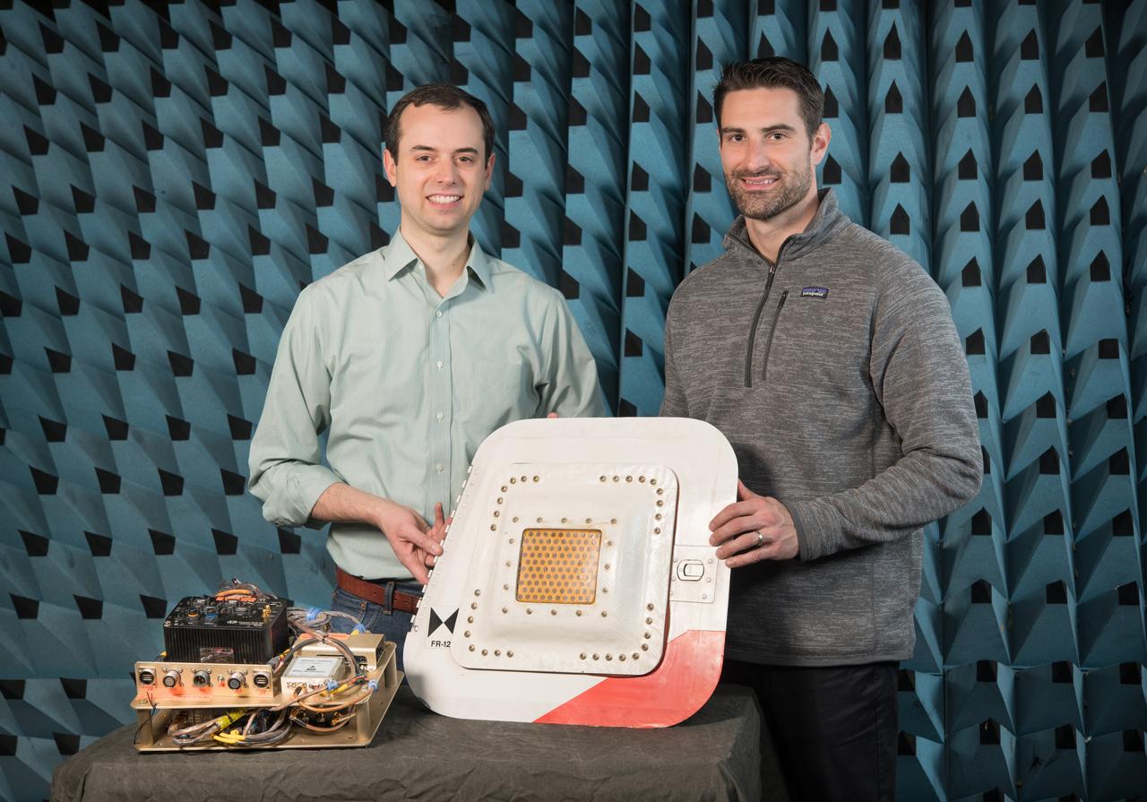
Flight Electronics Payload for Curved Confocal Lightweight Antenna Structures for Aeronautical Communications Technologies, CLAS-ACT, Phased Array Antenna on T-34-C Aircraft Door Flight Curved Confocal Lightweight Antenna Structures for Aeronautical Communications Technologies, CLAS-ACT, Phased Array Antenna Control / Flight Testing
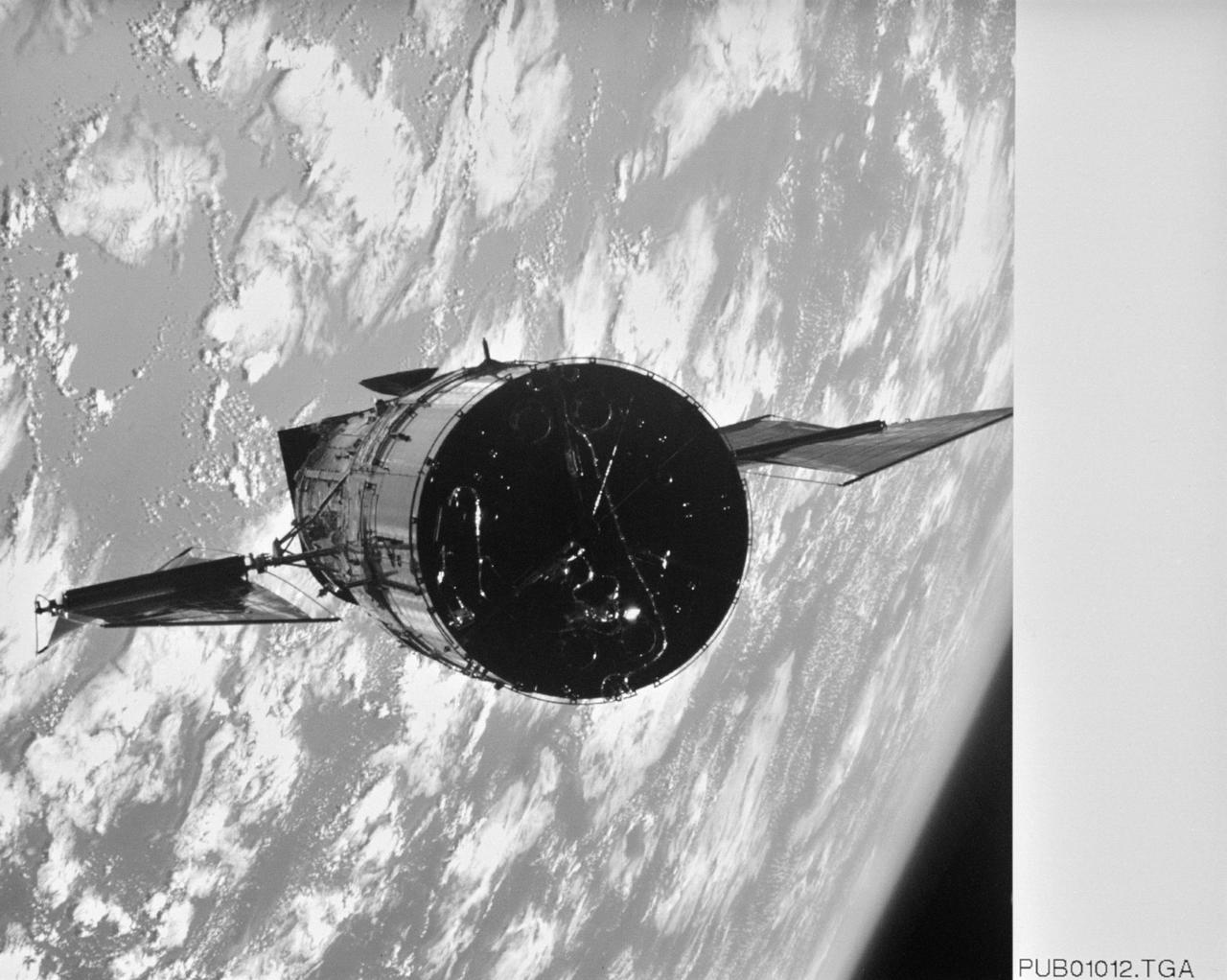
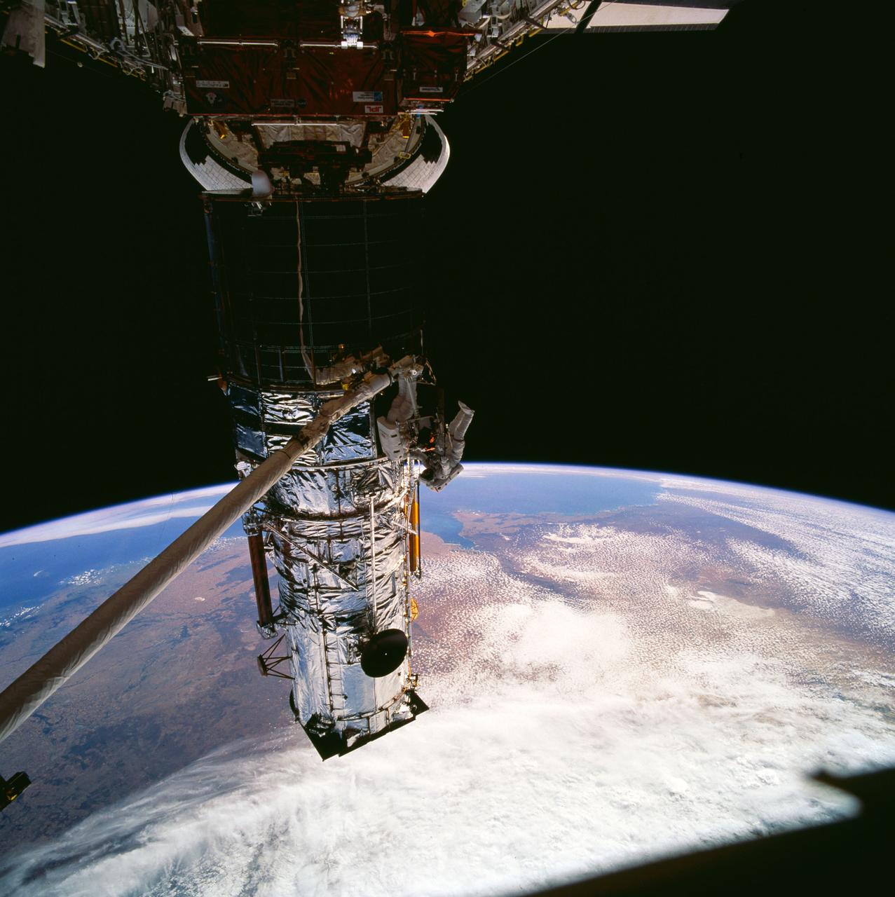
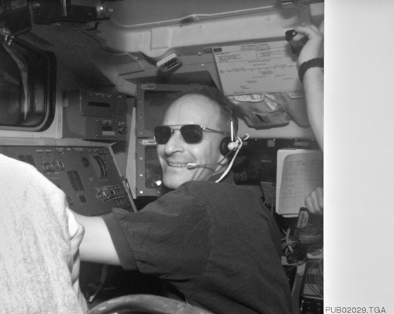
S61-E-008 (4 Dec 1993) --- This view of the Earth-orbiting Hubble Space Telescope (HST) was photographed with an Electronic Still Camera (ESC), and down linked to ground controllers soon afterward. This view was taken during rendezvous operations. Endeavour's crew captured the HST on December 4, 1993 in order to service the telescope. Over a period of five days, four of the crew members will work in alternating pairs outside Endeavour's shirt sleeve environment. Electronic still photography is a relatively new technology which provides the means for a handheld camera to electronically capture and digitize an image with resolution approaching film quality. The electronic still camera has flown as an experiment on several other shuttle missions.
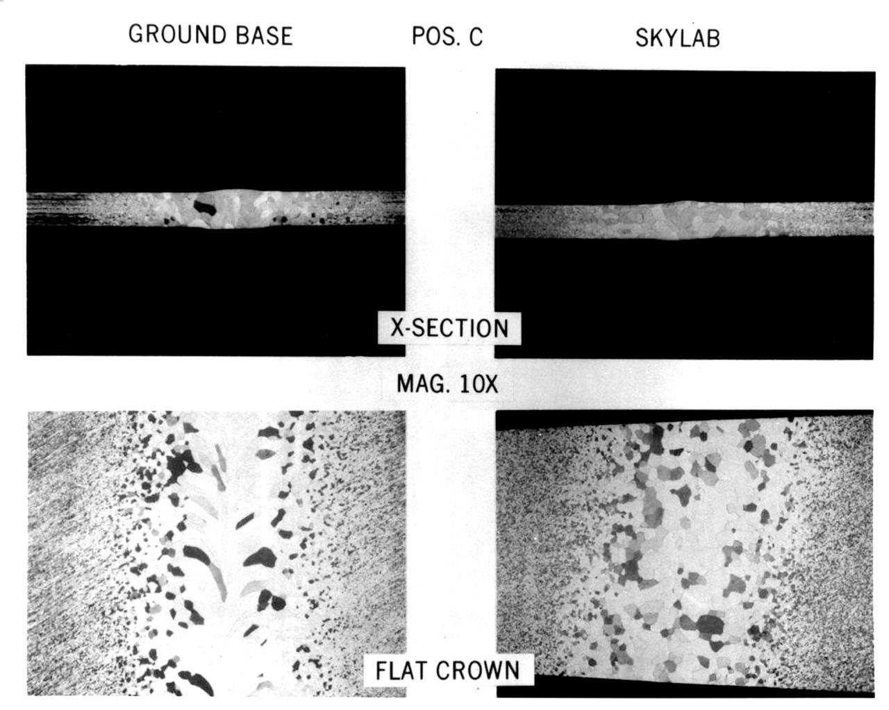
Comparison of ground-based (left) and Skylab (right) electron beam welds in pure tantalum (Ta) (10X magnification). Residual votices left behind in the ground-based sample after the electron beam passed were frozen into the grain structure. These occurred because of the rapid cooling rate at the high temperature. Although the thermal characteristics and electron beam travel speeds were comparable for the skylab sample, the residual vortices were erased in the grain structure. This may have been due to the fact that final grain size of the solidified material was smaller in the Skylab sample compared to the ground-based sample. The Skylab sample was processed in the M512 Materials Processing Facility (MPF) during Skylab SL-2 Mission. Principal Investigator was Richard Poorman.

Engineers at NASA's Jet Propulsion Laboratory – from left, Brandon Creager, Juan Gloria, Joshua Nachtigal, and Sonny Gutierrez – are shown assembling the electronics palette for the Coronagraph Instrument on NASA's Roman Space Telescope in December 2022. One of two main sections of the instrument, this layer houses the instrument electronics that receive instructions from the Roman spacecraft and send back the Coronagraph Instrument's scientific data. The electronics also control the mechanical components on the optical bench and the instrument heaters. https://photojournal.jpl.nasa.gov/catalog/PIA25435
STS061-102-010 (9 Dec 1993) --- Astronauts Jeffrey A. Hoffman (left) and F. Story Musgrave team to replace one of two Solar Array Drive Electronics (SADE) units on the Hubble Space Telescope (HST). Musgrave is standing on a foot restraint mounted on the end of the Space Shuttle Endeavour's Remote Manipulator System (RMS) arm. The black object, in upper left corner, is part of the window frame, through which this 70mm frame was exposed, inside Endeavour's cabin.
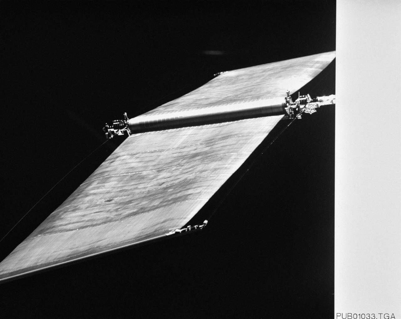
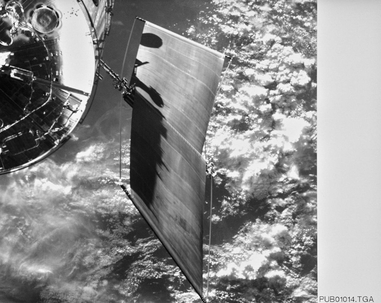
S61-E-002 (4 Dec 1993) --- This view, backdropped against the blackness of space shows one of two original Solar Arrays (SA) on the Hubble Space Telescope (HST). The scene was photographed from inside Endeavour's cabin with an Electronic Still Camera (ESC), and down linked to ground controllers soon afterward. This view features the minus V-2 panel. Endeavour's crew captured the HST on December 4, 1993 in order to service the telescope over a period of five days. Four of the crew members will work in alternating pairs outside Endeavour's shirt sleeve environment to service the giant telescope. Electronic still photography is a relatively new technology which provides the means for a handheld camera to electronically capture and digitize an image with resolution approaching film quality. The electronic still camera has flown as an experiment on several other shuttle missions.
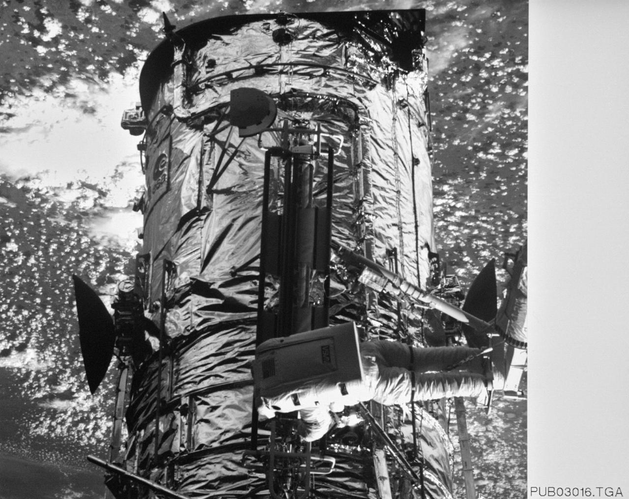
S61-E-001 (4 Dec 1993) --- This medium close-up view of the top portion of the Hubble Space Telescope (HST) was photographed with an Electronic Still Camera (ESC), and down linked to ground controllers soon afterward. Endeavour's crew captured the HST on December 4, 1993 in order to service the telescope over a period of five days. Four of the crew members will work in alternating pairs outside Endeavour's shirt sleeve environment to service the giant telescope. Electronic still photography is a relatively new technology which provides the means for a handheld camera to electronically capture and digitize an image with resolution approaching film quality. The electronic still camera has flown as an experiment on several other shuttle missions.

S61-E-003 (4 Dec 1993) --- This medium close-up view of one of two original Solar Arrays (SA) on the Hubble Space Telescope (HST) was photographed with an Electronic Still Camera (ESC), and down linked to ground controllers soon afterward. This view shows the cell side of the minus V-2 panel. Endeavour's crew captured the HST on December 4, 1993 in order to service the telescope over a period of five days. Four of the crew members will work in alternating pairs outside Endeavour's shirt sleeve environment to service the giant telescope. Electronic still photography is a relatively new technology which provides the means for a handheld camera to electronically capture and digitize an image with resolution approaching film quality. The electronic still camera has flown as an experiment on several other shuttle missions.
S61-E-020 (7 Dec 1993) --- This close-up view of one of two Solar Arrays (SA) on the Hubble Space Telescope (HST) was photographed with an Electronic Still Camera (ESC), and down linked to ground controllers soon afterward. Endeavour's crew captured the HST on December 4, 1993, in order to service the telescope over a period of five days. Four of the crew members will work in alternating pairs outside Endeavour's shirt sleeve environment to service the giant telescope. Electronic still photography is a relatively new technology which provides the means for a handheld camera to electronically capture and digitize an image with resolution approaching film quality. The electronic still camera has flown as an experiment on several other shuttle missions.
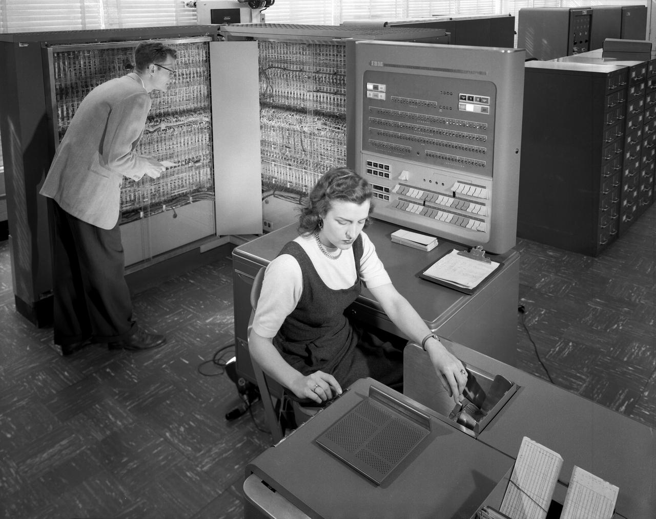
L57-989: Man and woman shown working with IBM type T04 electronic data processing machine.
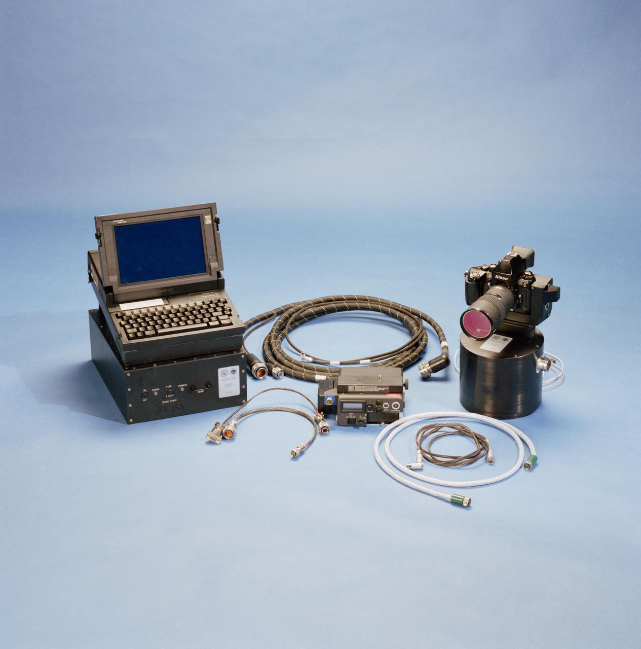
STS-53 Discovery, Orbiter Vehicle (OV) 103, Department of Defense (DOD) mission Hand-held Earth-oriented Real-time Cooperative, User-friendly, Location, targeting, and Environmental System (Hercules) spaceborne experiment equipment is documented in this table top view. HERCULES is a joint NAVY-NASA-ARMY payload designed to provide real-time high resolution digital electronic imagery and geolocation (latitude and longitude determination) of earth surface targets of interest. HERCULES system consists of (from left to right): a specially modified GRID Systems portable computer mounted atop NASA developed Playback-Downlink Unit (PDU) and the Naval Research Laboratory (NRL) developed HERCULES Attitude Processor (HAP); the NASA-developed Electronic Still Camera (ESC) Electronics Box (ESCEB) including removable imagery data storage disks and various connecting cables; the ESC (a NASA modified Nikon F-4 camera) mounted atop the NRL HERCULES Inertial Measurement Unit (HIMU) containing the three-axis ring-laser gyro.
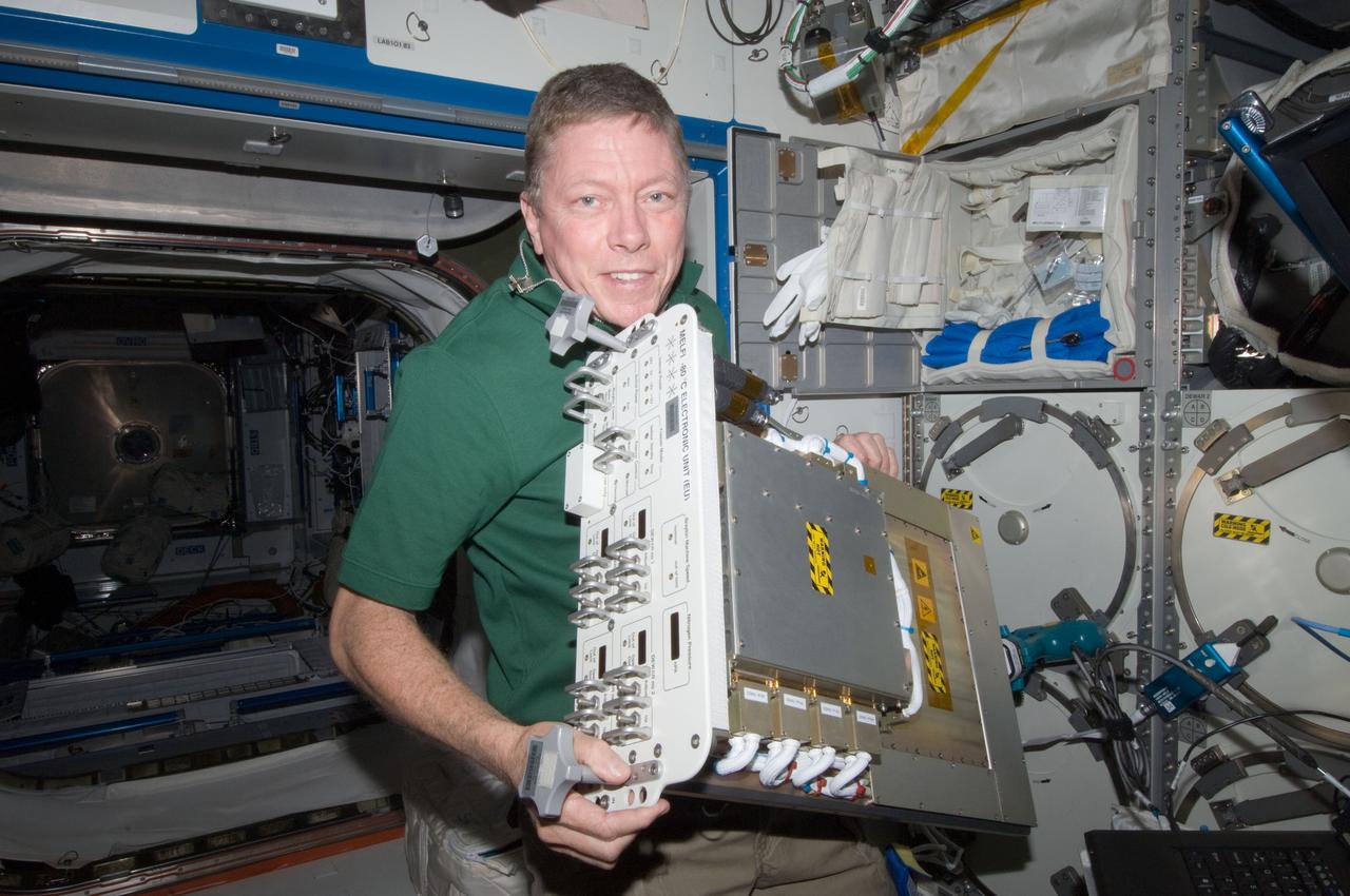
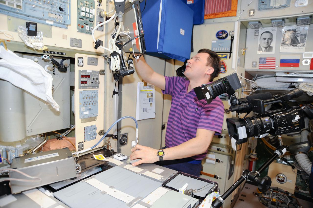
ISS028-E-013797 (1 July 2011) --- NASA astronaut Mike Fossum, Expedition 28 flight engineer, replaces a failed electronic unit for the Minus Eighty Laboratory Freezer for ISS 3 (MELFI-3) with a spare unit in the Kibo laboratory of the International Space Station.
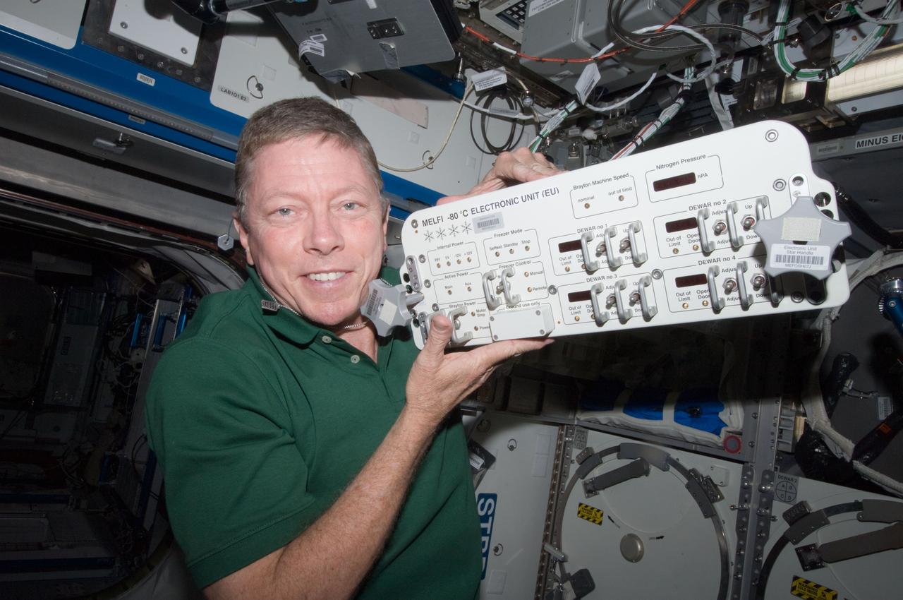
ISS028-E-013799 (1 July 2011) --- NASA astronaut Mike Fossum, Expedition 28 flight engineer, replaces a failed electronic unit for the Minus Eighty Laboratory Freezer for ISS 3 (MELFI-3) with a spare unit in the Kibo laboratory of the International Space Station.

STS073-E-5275 (3 Nov. 1995) --- Resort City of Acapulco appears in this north-looking view, photographed from the Earth-orbiting space shuttle Columbia with the Electronic Still Camera (ESC). The airport lies on a narrow neck of land between the sea and a large coastal lagoon. This mission marks the first time NASA has released in mid-flight electronically-downlinked color images that feature geographic subject matter.
S61-E-006 (5 Dec 1993) --- The robot arm controlling work of Swiss scientist Claude Nicollier was photographed with an Electronic Still Camera (ESC), and down linked to ground controllers soon afterward. With the mission specialist's assistance, Endeavour's crew captured the Hubble Space Telescope (HST) on December 4, 1993. Four of the seven crew members will work in alternating pairs outside Endeavour's shirt sleeve environment to service the giant telescope. Electronic still photography is a relatively new technology which provides the means for a handheld camera to electronically capture and digitize an image with resolution approaching film quality. The electronic still camera has flown as an experiment on several other shuttle missions.
S61-E-011 (5 Dec 1993) --- This view of astronaut Kathryn C. Thornton working on the Hubble Space Telescope (HST) was photographed with an Electronic Still Camera (ESC), and down linked to ground controllers soon afterward. Thornton, anchored to the end of the Remote Manipulator System (RMS) arm, is installing the +V2 Solar Array Panel as a replacement for the original one removed earlier. Electronic still photography is a relatively new technology which provides the means for a handheld camera to electronically capture and digitize an image with resolution approaching film quality. The electronic still camera has flown as an experiment on several other shuttle missions.

Mechanical technician, Thomas Huber and mechanical engineer Peter Steigner, install an electronic box onto the Ocean Color Instrument (OCI) deck. Once the remaining boxes are installed, electrical connections will be made and testing will be performed. OCI is a highly advanced optical spectrometer that will be used to measure properties of light over portions of the electromagnetic spectrum. It will enable continuous measurement of light at finer wavelength resolution than previous NASA satellite sensors, extending key system ocean color data records for climate studies. OCI is PACE's (Plankton, Aerosol, Cloud, ocean Ecosystem) primary sensor built at Goddard Space Flight Center in Greenbelt, MD.
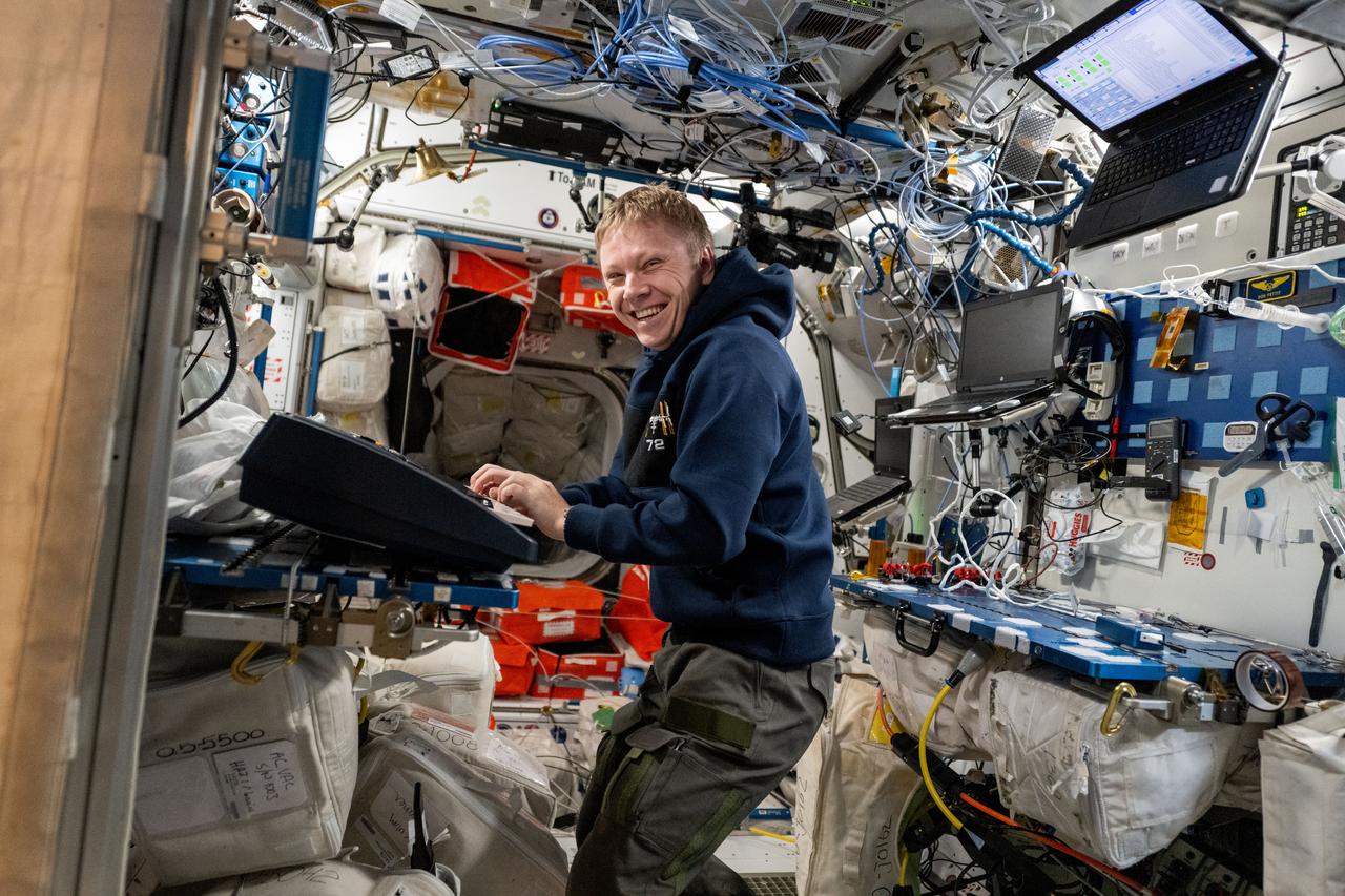
iss072e143768 (Nov. 1, 2024) --- Roscosmos cosmonaut and Expedition 72 Flight Engineer Aleksandr Gorbunov plays an electronic keyboard aboard the International Space Station's Harmony module.
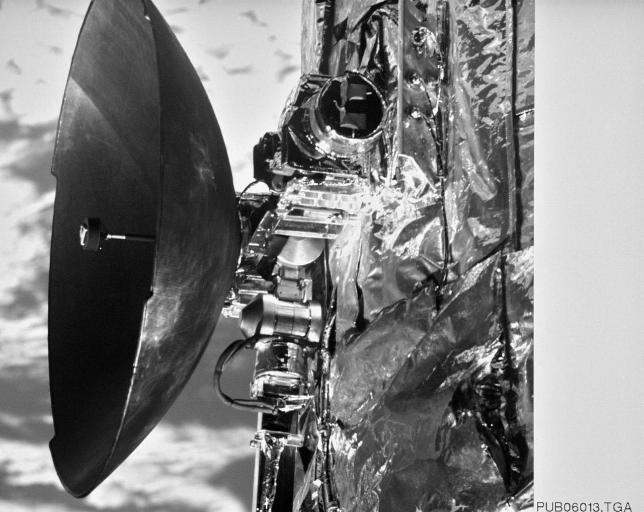
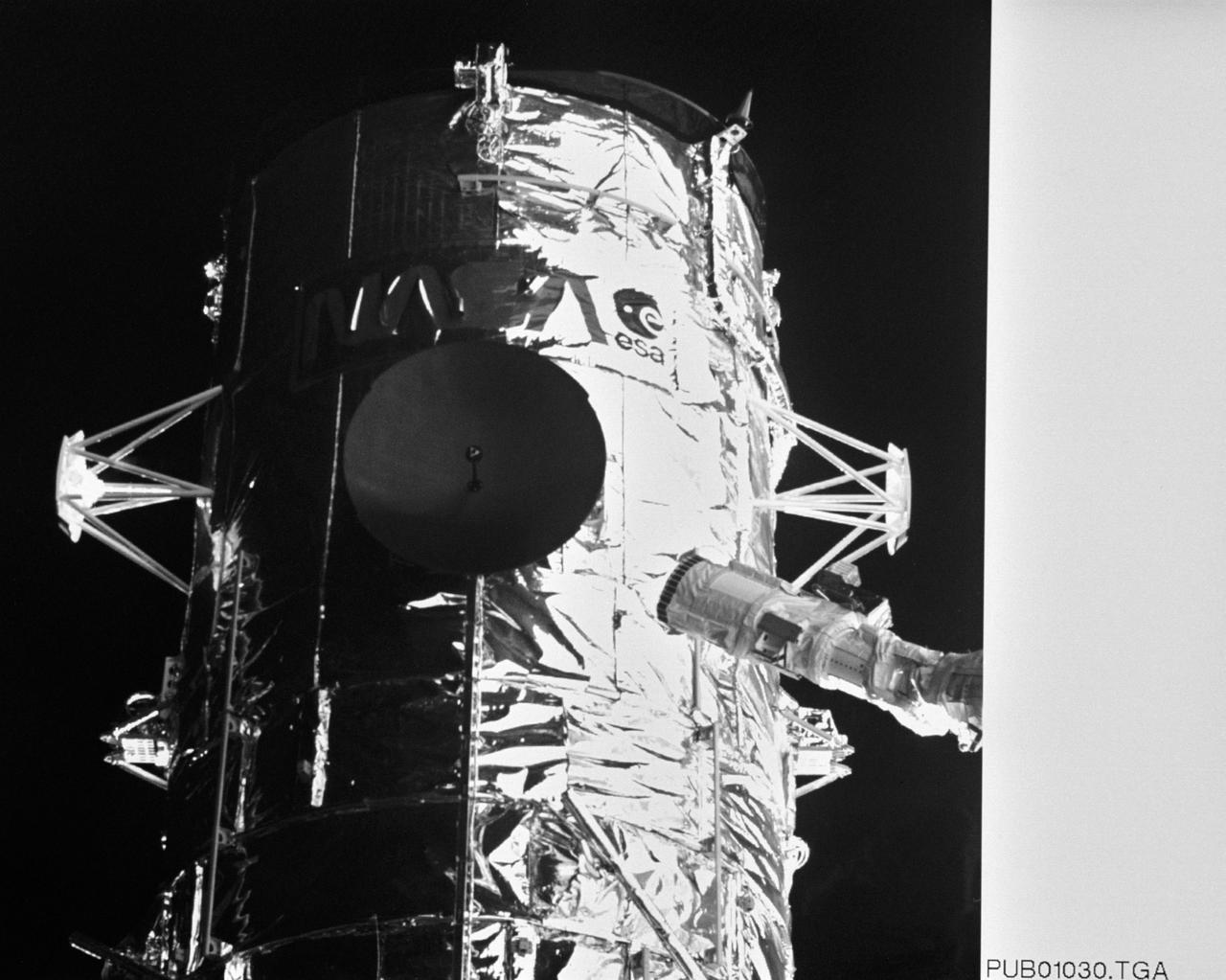
S61-E-021 (7 Dec 1993) --- This close-up view of one of two High Gain Antennae (HGA) on the Hubble Space Telescope (HST) was photographed with an Electronic Still Camera (ESC), and down linked to ground controllers soon afterward. Endeavour's crew captured the HST on December 4, 1993 in order to service the telescope over a period of five days. Four of the crew members have been working in alternating pairs outside Endeavour's shirt sleeve environment to service the giant telescope. Electronic still photography is a relatively new technology which provides the means for a handheld camera to electronically capture and digitize an image with resolution approaching film quality. The electronic still camera has flown as an experiment on several other shuttle missions.
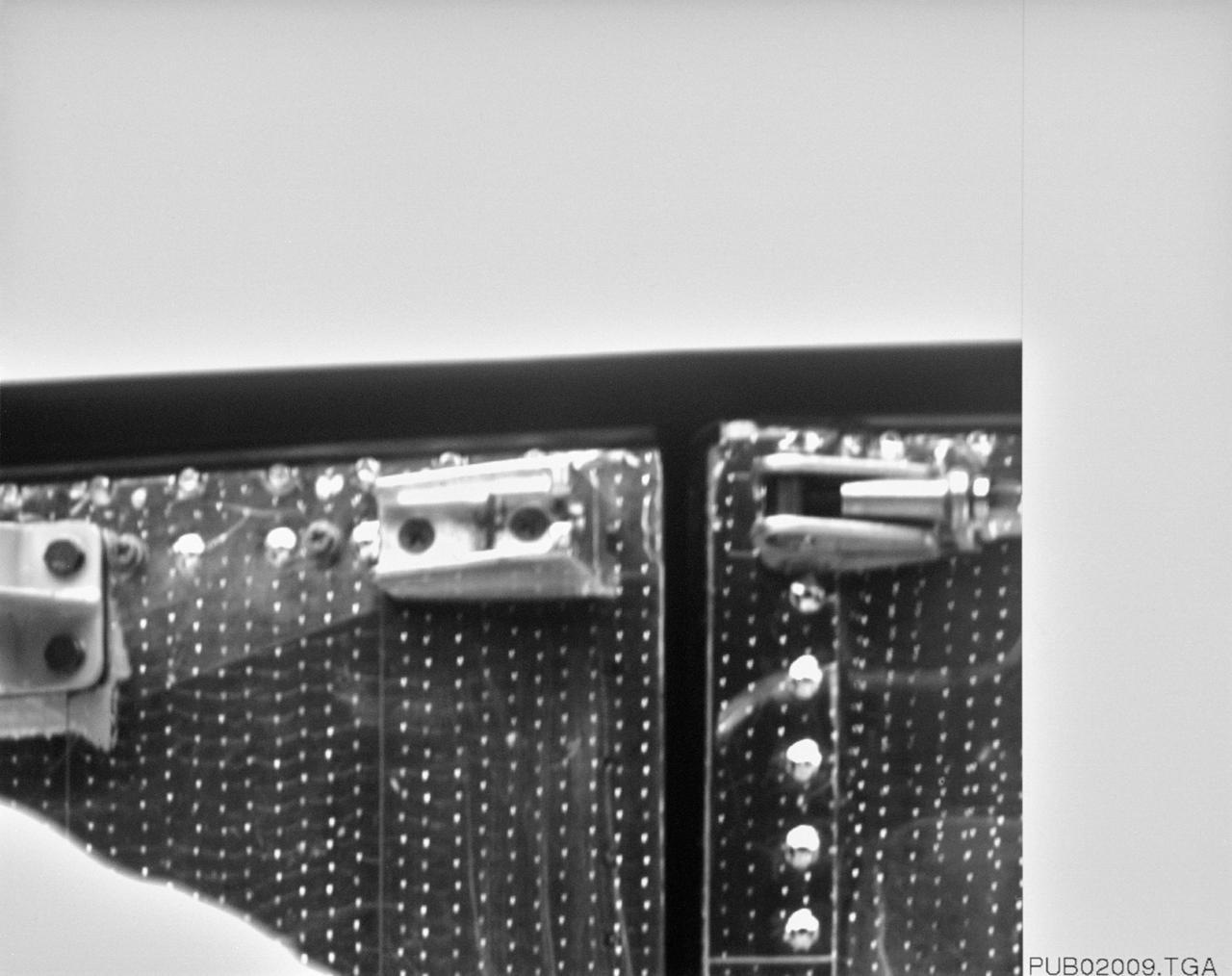
S61-E-004 (4 Dec 1993) --- This close-up view of a latch on the minus V3 aft shroud door of the Hubble Space Telescope (HST) was photographed with an Electronic Still Camera (ESC), and down linked to ground controllers soon afterward. Endeavour's crew captured the HST on December 4, 1993 in order to service the telescope. Over a period of five days, four of the seven crew members will work in alternating pairs outside Endeavour's shirt sleeve environment to service the giant telescope. Electronic still photography is a relatively new technology which provides the means for a handheld camera to electronically capture and digitize an image with resolution approaching film quality. The electronic still camera has flown as an experiment on several other shuttle missions.
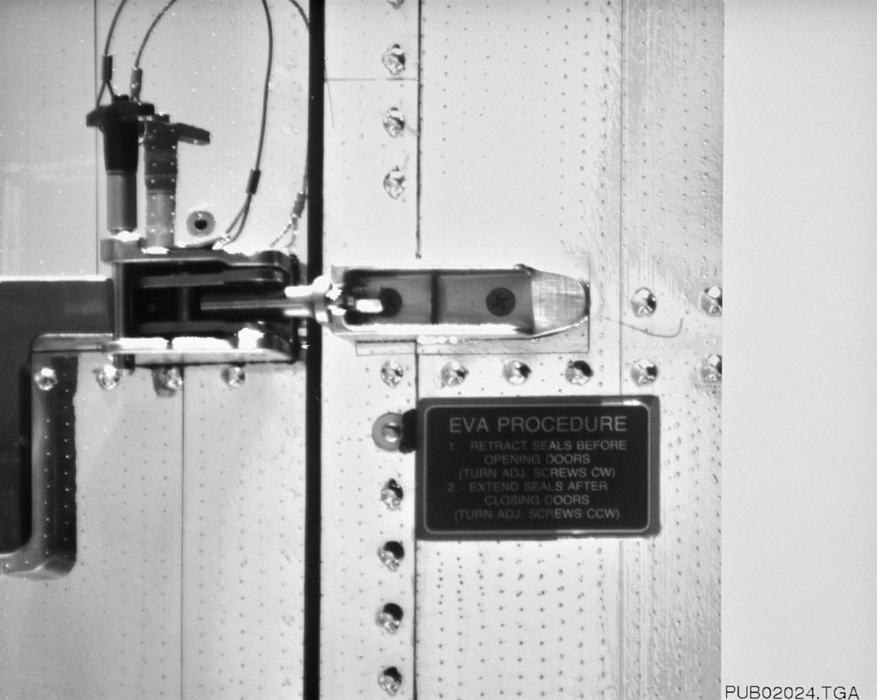
S61-E-010 (4 Dec 1993) --- This close-up view of a latch on the minus V3 aft shroud door of the Hubble Space Telescope (HST) was photographed with an Electronic Still Camera (ESC), and down linked to ground controllers soon afterward. Endeavour's crew captured the HST on December 4, 1993 in order to service the telescope over a period of five days. Four of the crew members will work in alternating pairs outside Endeavour's shirt sleeve environment to service the giant telescope. Electronic still photography is a relatively new technology which provides the means for a handheld camera to electronically capture and digitize an image with resolution approaching film quality. The electronic still camera has flown as an experiment on several other shuttle missions.
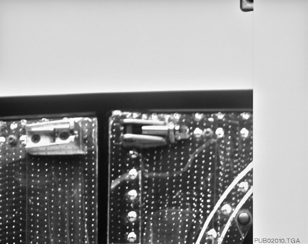
S61-E-005 (4 Dec 1993) --- This close-up view of a latch on the minus V3 aft shroud door of the Hubble Space Telescope (HST) was photographed with an Electronic Still Camera (ESC), and down linked to ground controllers soon afterward. Endeavour's crew captured the HST on December 4, 1993 in order to service the telescope. Over a period of five days, four of the seven crew members will work in alternating pairs outside Endeavour's shirt sleeve environment to service the giant telescope. Electronic still photography is a relatively new technology which provides the means for a handheld camera to electronically capture and digitize an image with resolution approaching film quality. The electronic still camera has flown as an experiment on several other shuttle missions.

S61-E-012 (5 Dec 1993) --- This view of astronauts Kathryn C. Thornton (top) and Thomas D. Akers working on the Hubble Space Telescope (HST) was photographed with an Electronic Still Camera (ESC), and down linked to ground controllers soon afterward. Thornton, anchored to the end of the Remote Manipulator System (RMS) arm, is teaming with Akers to install the +V2 Solar Array Panel as a replacement for the original one removed earlier. Akers uses tethers and a foot restraint to remain in position for the task. Electronic still photography is a relatively new technology which provides the means for a handheld camera to electronically capture and digitize an image with resolution approaching film quality. The electronic still camera has flown as an experiment on several other shuttle missions.

S61-E-014 (5 Dec 1993) --- This view of astronauts Kathryn C. Thornton (bottom) and Thomas D. Akers working on the Hubble Space Telescope (HST) was photographed with an Electronic Still Camera (ESC), and down linked to ground controllers soon afterward. Thornton, anchored to the end of the Remote Manipulator System (RMS) arm, is teaming with Akers to install the +V2 Solar Array Panel as a replacement for the original one removed earlier. Akers uses tethers and a foot restraint to remain in position for the task. Electronic still photography is a relatively new technology which provides the means for a handheld camera to electronically capture and digitize an image with resolution approaching film quality. The electronic still camera has flown as an experiment on several other shuttle missions.
S61-E-009 (4 Dec 1993) --- This view of one of two High Gain Antennae (HGA) on the Hubble Space Telescope (HST) was photographed with an Electronic Still Camera (ESC). The scene was down linked to ground controllers soon after the Space Shuttle Endeavour caught up to the orbiting telescope 320 miles above Earth. Shown here before grapple, the HST was captured on December 4, 1993 in order to service the telescope. Over a period of five days, four of the seven STS-61 crew members will work in alternating pairs outside Endeavour's shirt sleeve environment. Electronic still photography is a relatively new technology which provides the means for a handheld camera to electronically capture and digitize an image with resolution approaching film quality. The electronic still camera has flown as an experiment on several other shuttle missions.
ISS034-E-051551 (21 Feb. 2013) --- Cosmonaut Roman Romanenko, Expedition 34 flight engineer, works with the Electronic Nose hardware in the Zvezda service module aboard the International Space Station in Earth orbit. This hardware is used to measure contamination in the environment should there be hard to detect chemical leaks or spills.
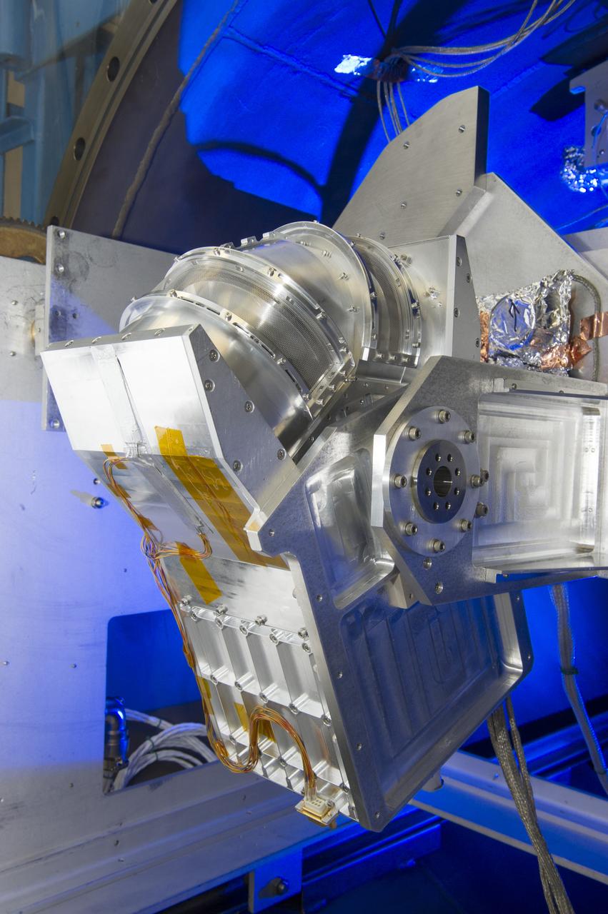
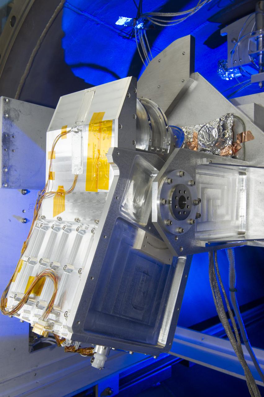
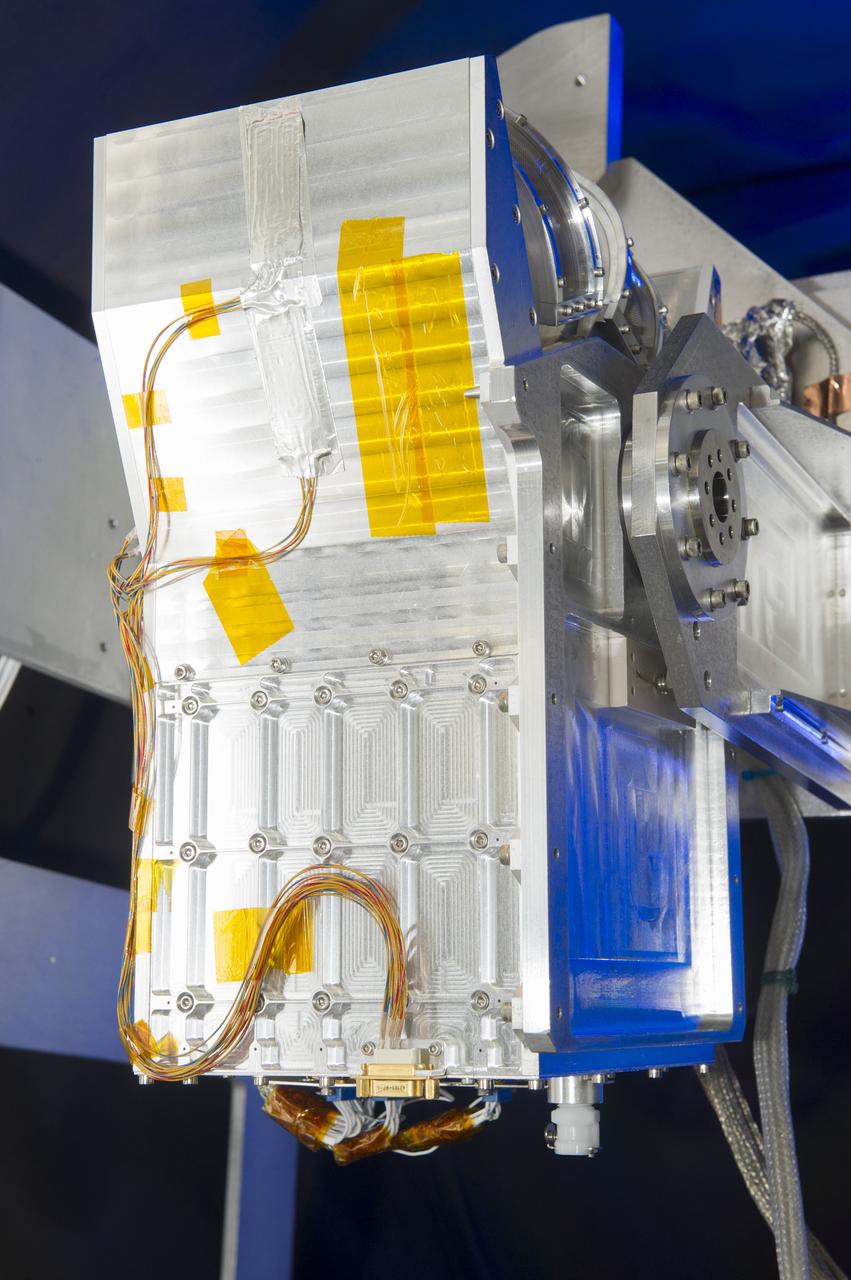
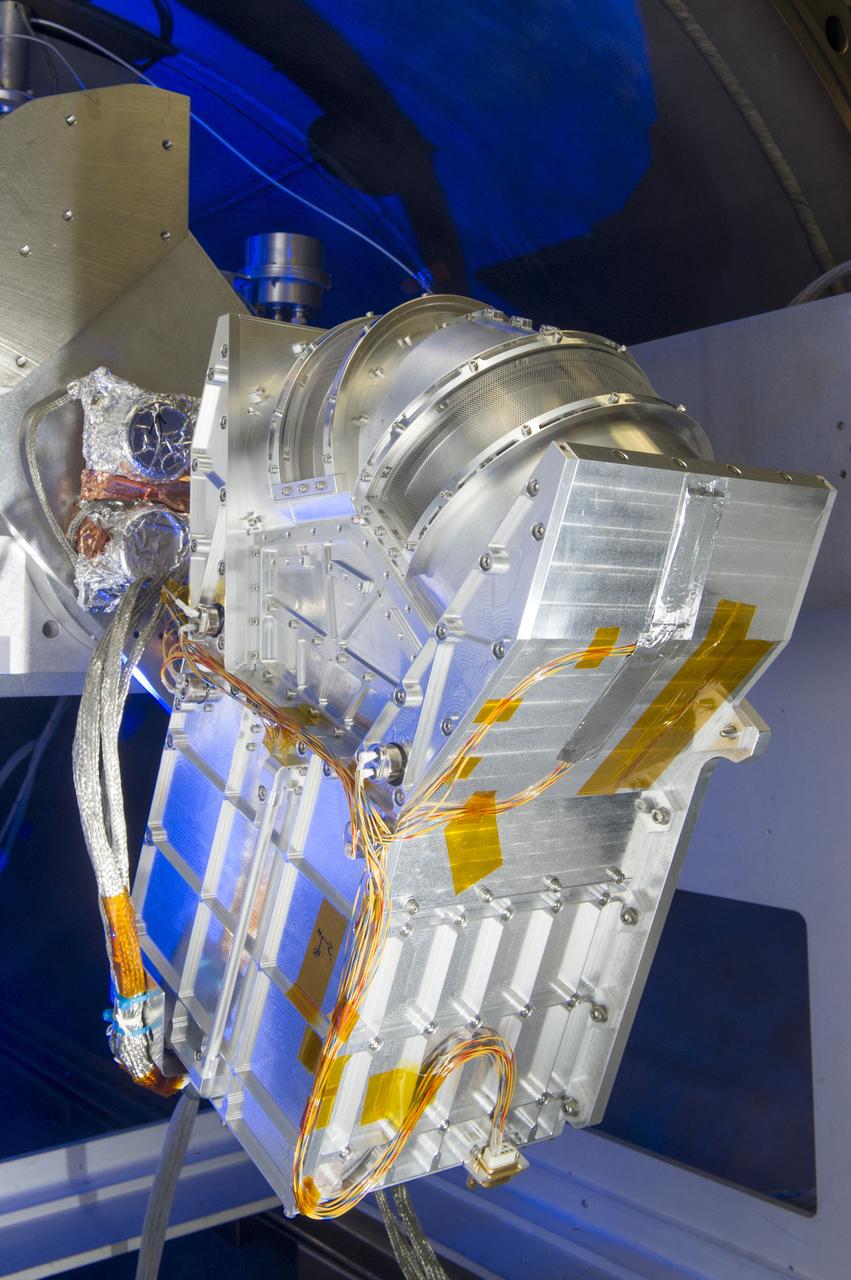
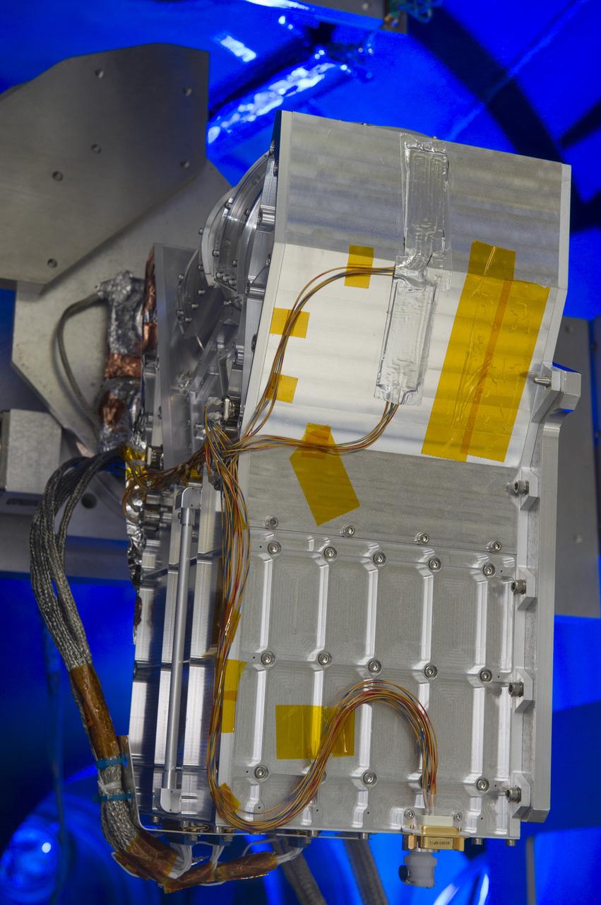
DUAL ION SPECTROMETER (DIS) ENGINEERING TEST UNIT (ETU) AT THE LOW ENERGY ELECTRON AND ION FACILITY (LEEIF), NSSTC
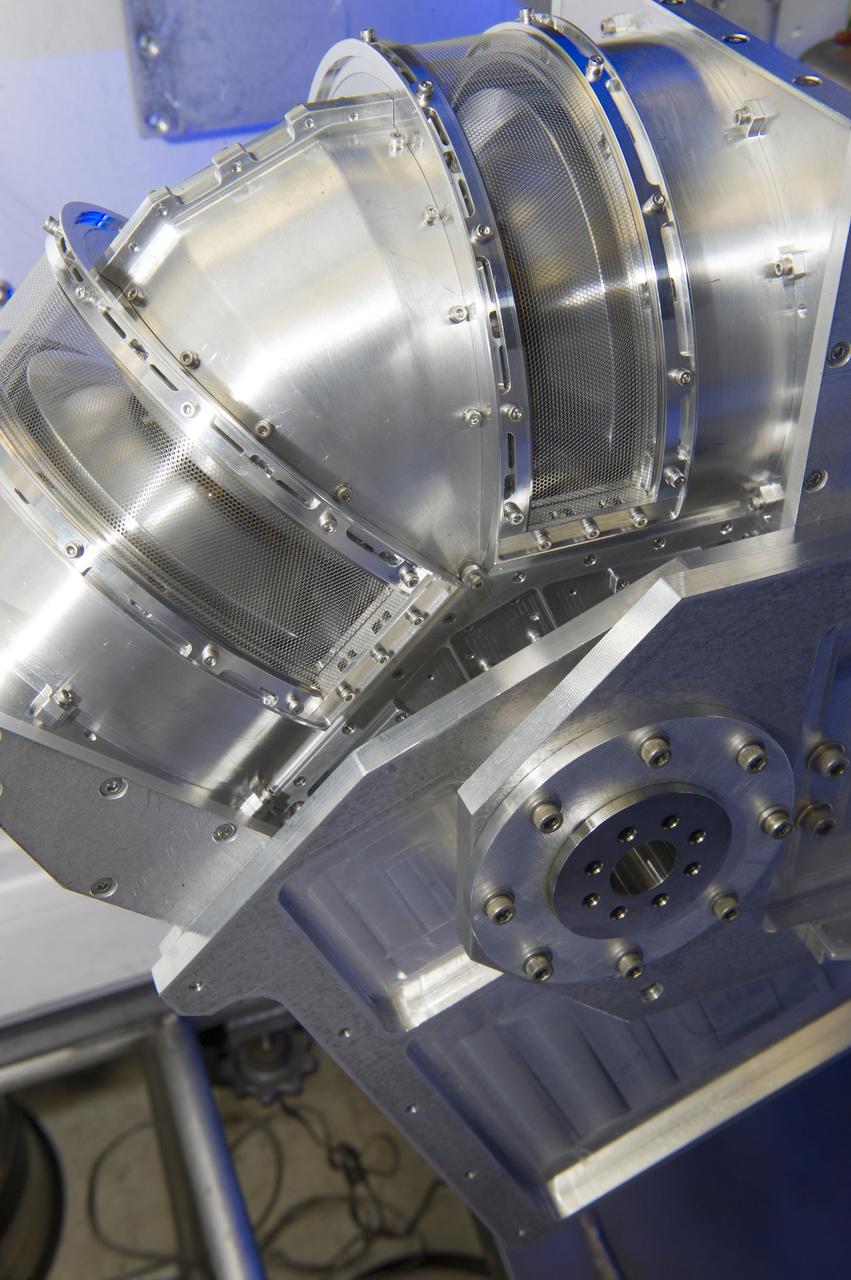
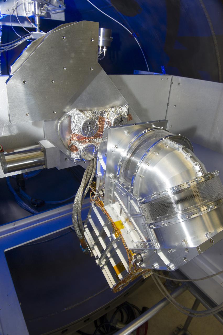
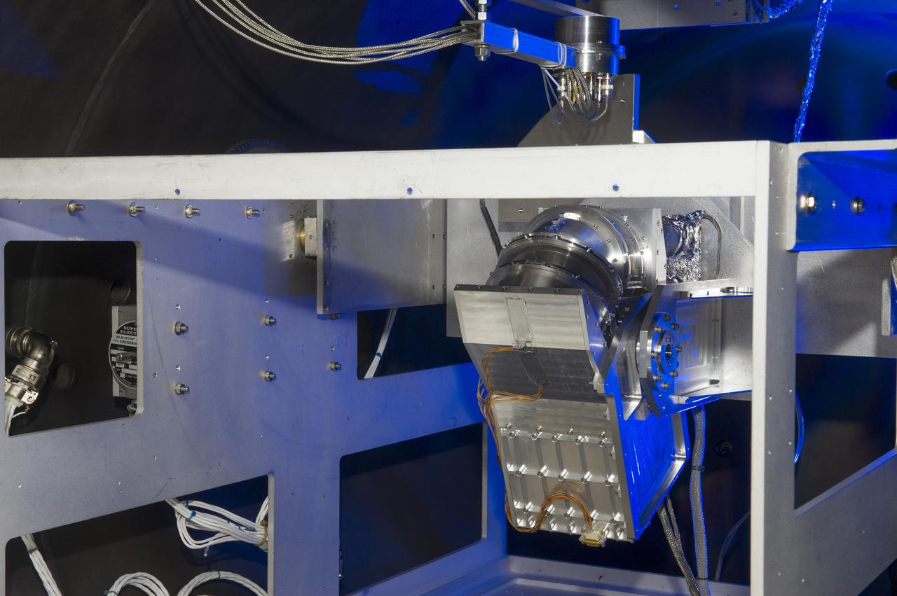
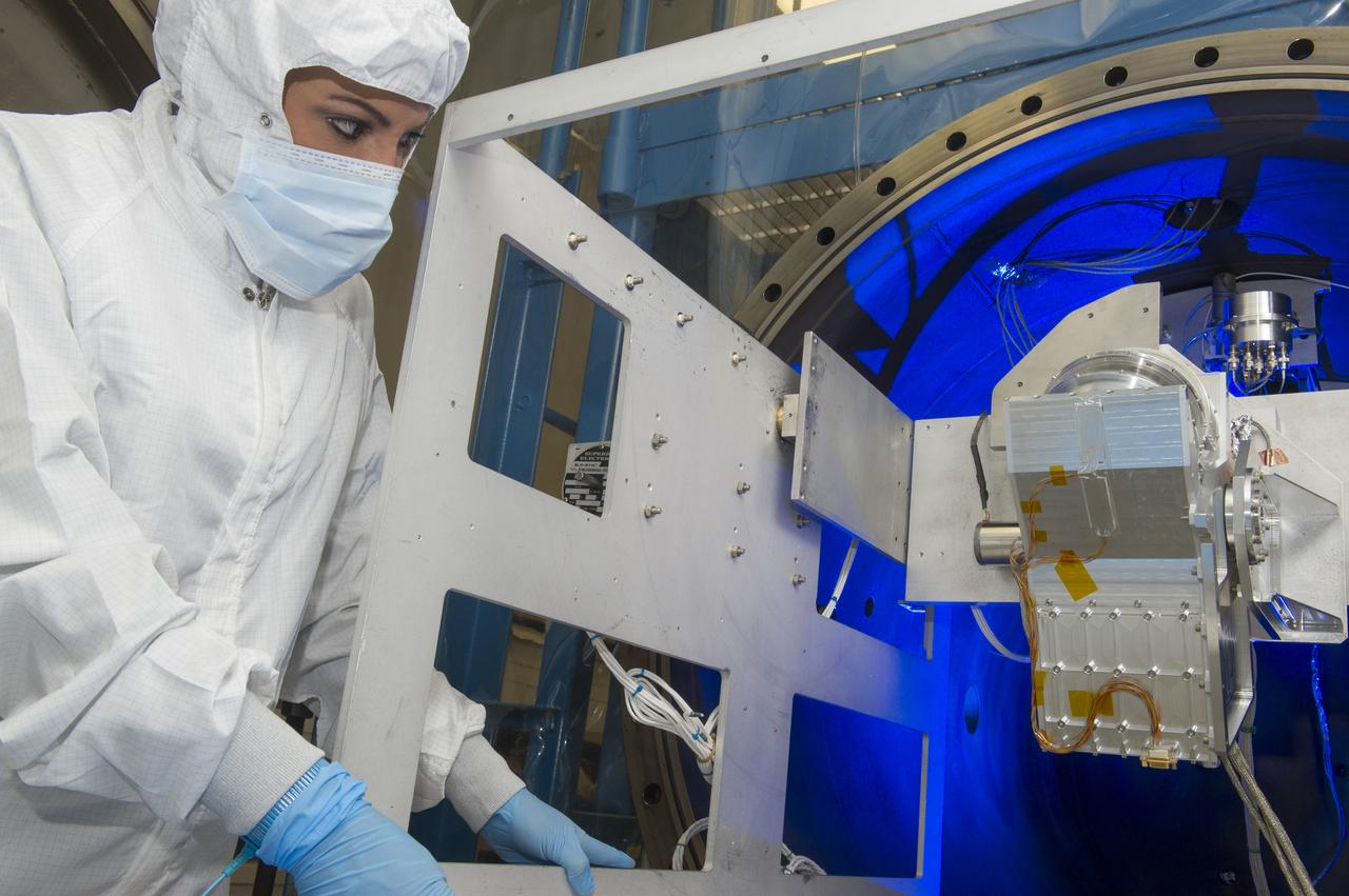
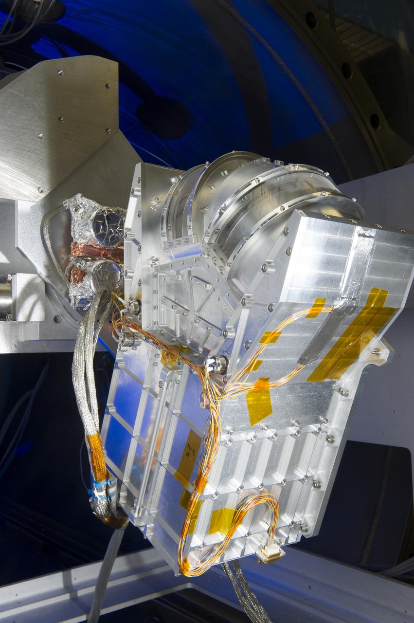
DUAL ION SPECTROMETER (DIS) ENGINEERING TEST UNIT (ETU) AT THE LOW ENERGY ELECTRON AND ION FACILITY (LEEIF), NSSTC
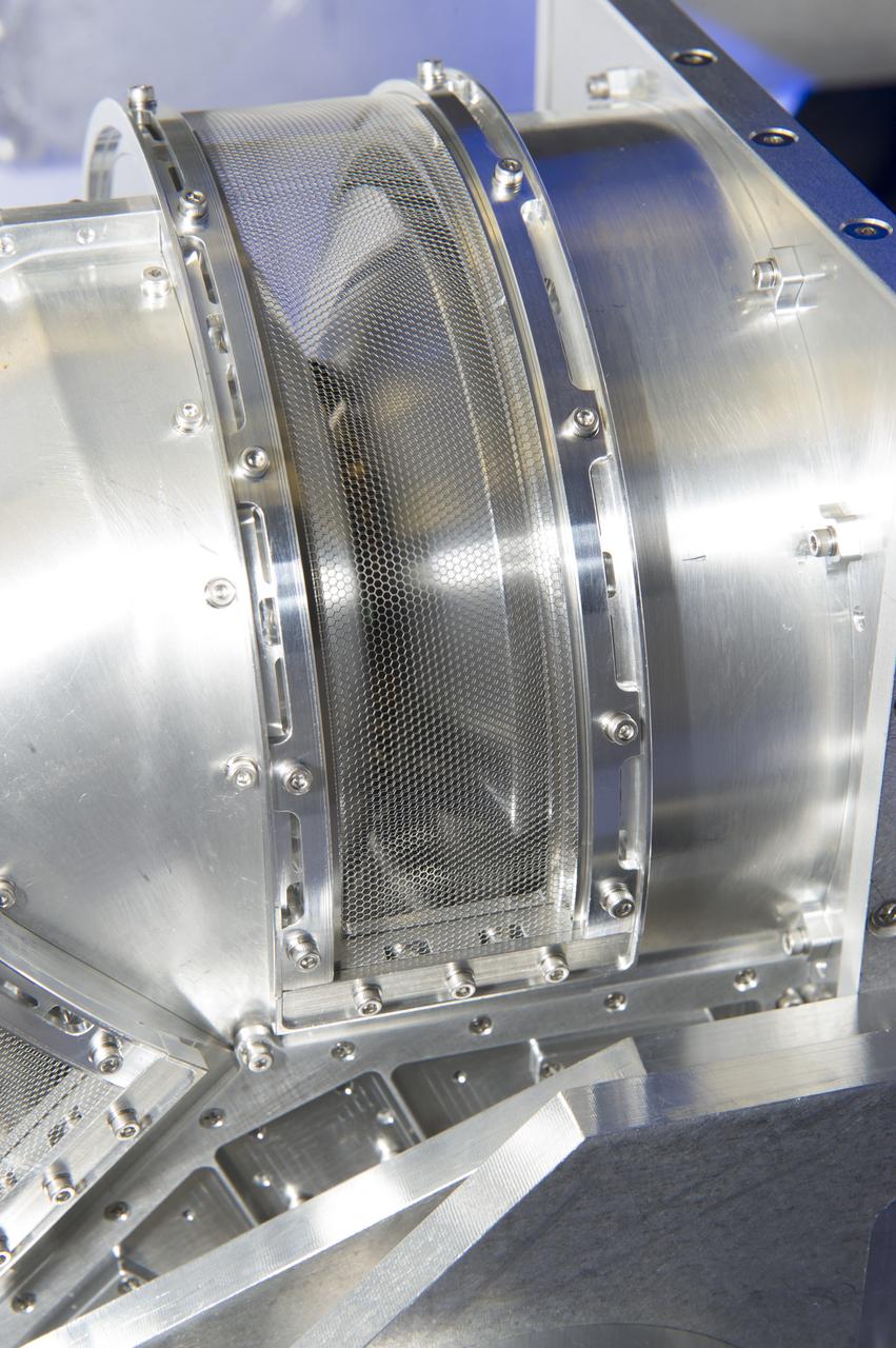
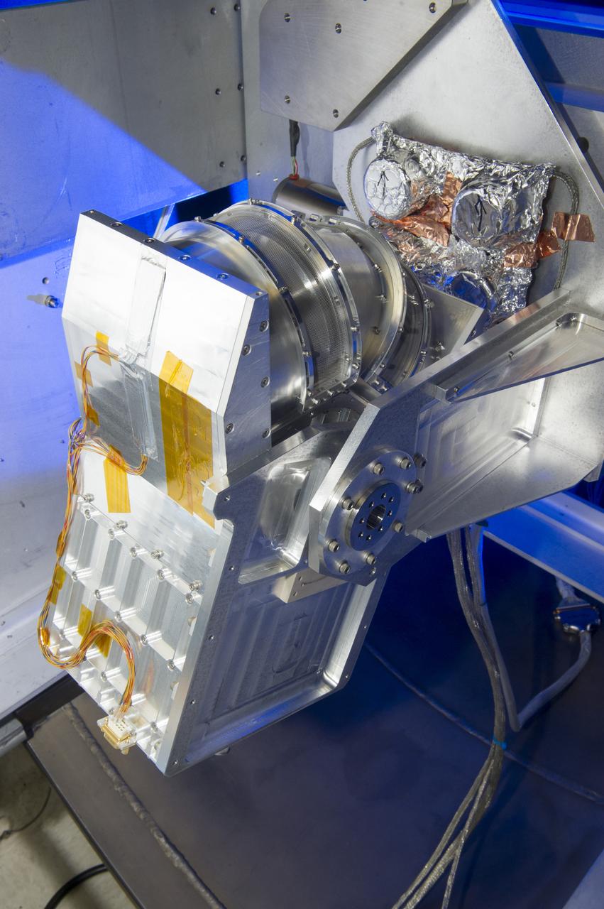
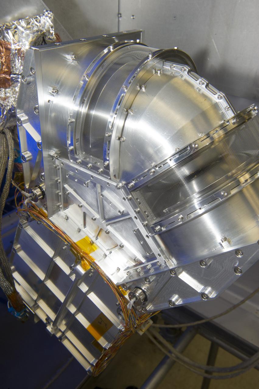
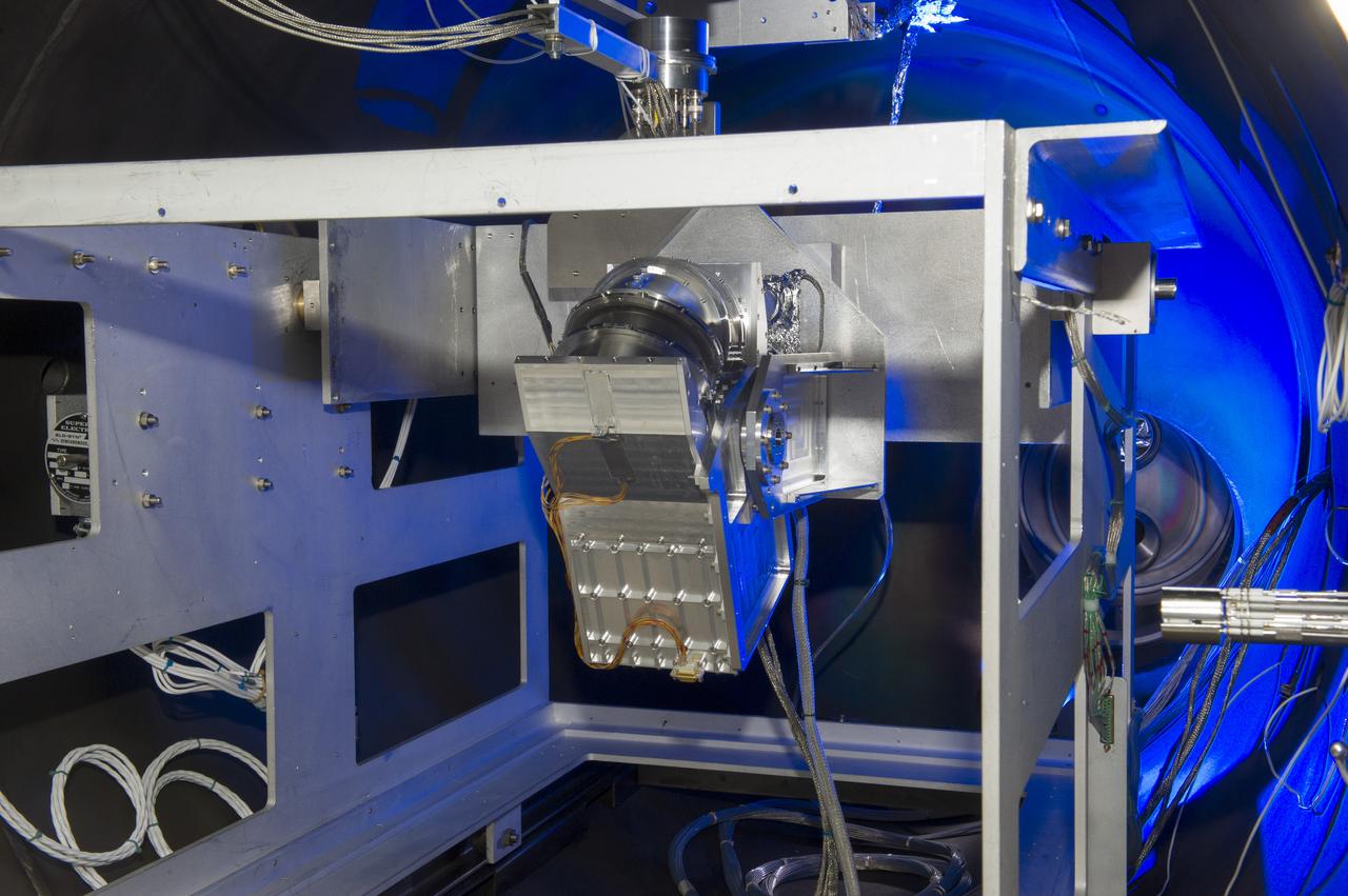
DUAL ION SPECTROMETER (DIS) ENGINEERING TEST UNIT (ETU) AT THE LOW ENERGY ELECTRON AND ION FACILITY (LEEIF), NSSTC
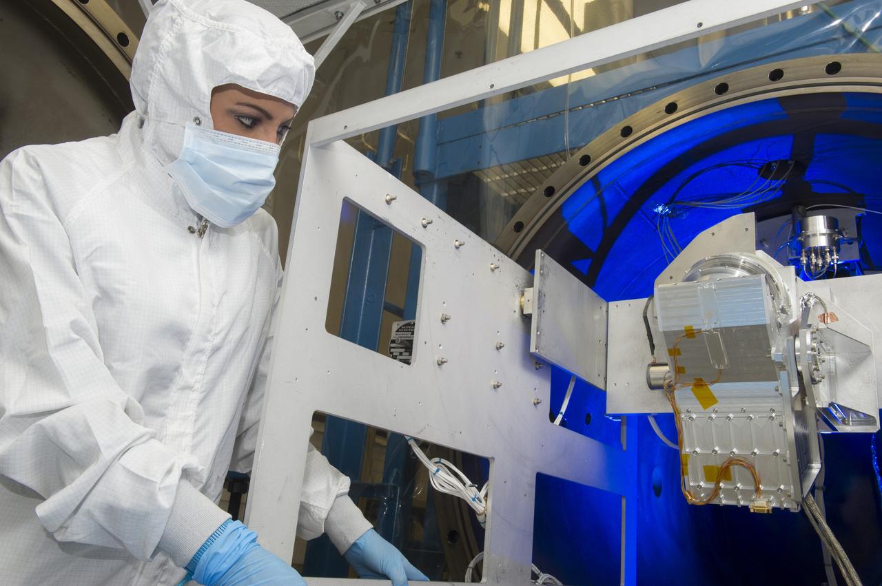
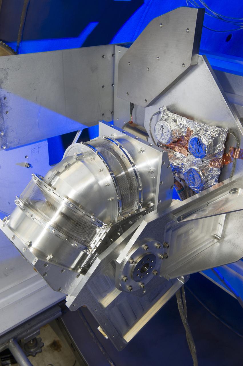
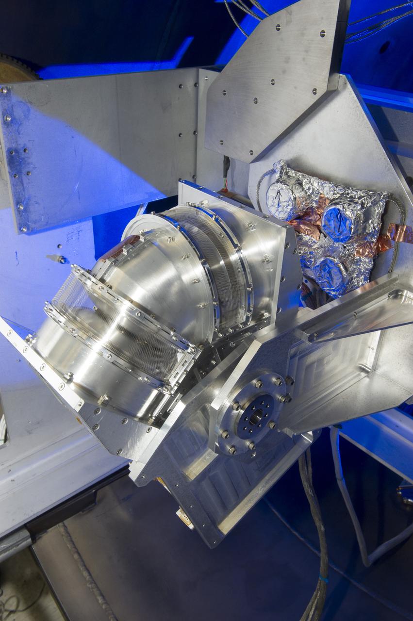
DUAL ION SPECTROMETER (DIS) ENGINEERING TEST UNIT (ETU) AT THE LOW ENERGY ELECTRON AND ION FACILITY (LEEIF), NSSTC
DUAL ION SPECTROMETER (DIS) ENGINEERING TEST UNIT (ETU) AT THE LOW ENERGY ELECTRON AND ION FACILITY (LEEIF), NSSTC
DUAL ION SPECTROMETER (DIS) ENGINEERING TEST UNIT (ETU) AT THE LOW ENERGY ELECTRON AND ION FACILITY (LEEIF), NSSTC
DUAL ION SPECTROMETER (DIS) ENGINEERING TEST UNIT (ETU) AT THE LOW ENERGY ELECTRON AND ION FACILITY (LEEIF), NSSTC
DUAL ION SPECTROMETER (DIS) ENGINEERING TEST UNIT (ETU) AT THE LOW ENERGY ELECTRON AND ION FACILITY (LEEIF), NSSTC
DUAL ION SPECTROMETER (DIS) ENGINEERING TEST UNIT (ETU) AT THE LOW ENERGY ELECTRON AND ION FACILITY (LEEIF), NSSTC
DUAL ION SPECTROMETER (DIS) ENGINEERING TEST UNIT (ETU) AT THE LOW ENERGY ELECTRON AND ION FACILITY (LEEIF), NSSTC

DUAL ION SPECTROMETER (DIS) ENGINEERING TEST UNIT (ETU) AT THE LOW ENERGY ELECTRON AND ION FACILITY (LEEIF), NSSTC
DUAL ION SPECTROMETER (DIS) ENGINEERING TEST UNIT (ETU) AT THE LOW ENERGY ELECTRON AND ION FACILITY (LEEIF), NSSTC
DUAL ION SPECTROMETER (DIS) ENGINEERING TEST UNIT (ETU) AT THE LOW ENERGY ELECTRON AND ION FACILITY (LEEIF), NSSTC
DUAL ION SPECTROMETER (DIS) ENGINEERING TEST UNIT (ETU) AT THE LOW ENERGY ELECTRON AND ION FACILITY (LEEIF), NSSTC
DUAL ION SPECTROMETER (DIS) ENGINEERING TEST UNIT (ETU) AT THE LOW ENERGY ELECTRON AND ION FACILITY (LEEIF), NSSTC
DUAL ION SPECTROMETER (DIS) ENGINEERING TEST UNIT (ETU) AT THE LOW ENERGY ELECTRON AND ION FACILITY (LEEIF), NSSTC
DUAL ION SPECTROMETER (DIS) ENGINEERING TEST UNIT (ETU) AT THE LOW ENERGY ELECTRON AND ION FACILITY (LEEIF), NSSTC
DUAL ION SPECTROMETER (DIS) ENGINEERING TEST UNIT (ETU) AT THE LOW ENERGY ELECTRON AND ION FACILITY (LEEIF), NSSTC
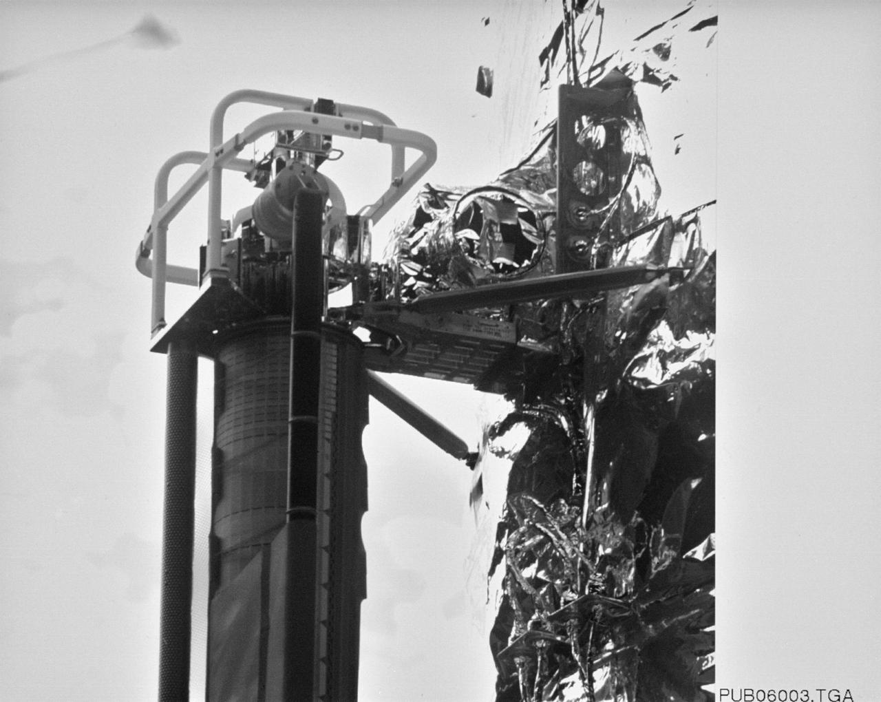
S61-E-015 (6 Dec 1993) --- A close-up view of the aft part of the new Wide Field/Planetary Camera (WFPC-II) installed on the Hubble Space Telescope (HST). WFPC-II was photographed with the Electronic Still Camera (ESC) from inside Endeavour's cabin as astronauts F. Story Musgrave and Jeffrey A. Hoffman moved it from its stowage position onto the giant telescope. Electronic still photography is a relatively new technology which provides the means for a handheld camera to electronically capture and digitize an image with resolution approaching film quality. The electronic still camera has flown as an experiment on several other shuttle missions.
Researchers at the Lewis Research Center had been studying different methods of electric rocket propulsion since the mid-1950s. Harold Kaufman created the first successful engine, the electron bombardment ion engine, in the early 1960s. Over the ensuing decades Lewis researchers continued to advance the original ion thruster concept. A Space Electric Rocket Test (SERT) spacecraft was launched in June 1964 to test Kaufman’s engine in space. SERT I had one cesium engine and one mercury engine. The suborbital flight was only 50 minutes in duration but proved that the ion engine could operate in space. This was followed in 1966 by the even more successful SERT II, which operated on and off for over ten years. Lewis continued studying increasingly more powerful ion thrusters. These electric engines created and accelerated small particles of propellant material to high exhaust velocities. Electric engines have a very small amount of thrust and are therefore not capable of lifting a spaceship from the surface of the Earth. Once lofted into orbit, however, electric engines are can produce small, continuous streams of thrust for several years.

iss073e0547544 (Aug. 27, 2025) --- Roscosmos cosmonaut and Expedition 73 Commander Sergey Ryzhikov is pictured during electronics maintenance at the beginning of his shift aboard the International Space Station.
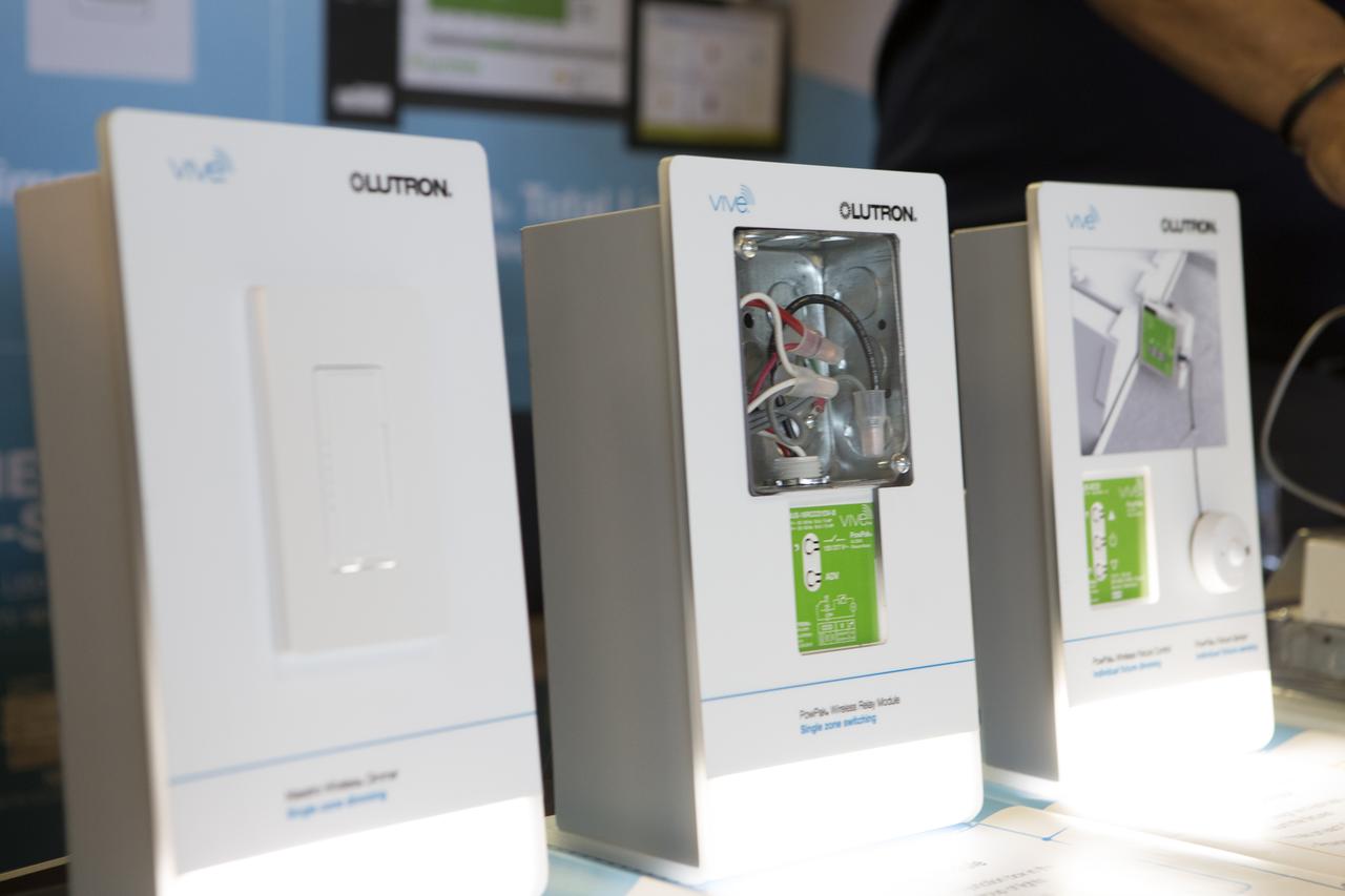
Shown are some of the devices from Lutron Electronics Co., a lighting control company, during Energy Awareness Day at the Multi-Function Facility on Oct. 20. Every third Thursday of October, civil servants, contractors and several energy utilities promote the awareness of our sustainability goals at Kennedy Space Center and at home. Photo credit: Cory Huston

NASA's highly modified F-15A (Serial #71-0287) used for digital electronic flight and engine control systems research, at sunrise on the ramp at the Dryden Flight Research Facility, Edwards, California. The F-15 was called the HIDEC (Highly Integrated Digital Electronic Control) flight facility. Research programs flown on the testbed vehicle have demonstrated improved rates of climb, fuel savings, and engine thrust by optimizing systems performance. The aircraft also tested and evaluated a computerized self-repairing flight control system for the Air Force that detects damaged or failed flight control surfaces. The system then reconfigures undamaged control surfaces so the mission can continue or the aircraft is landed safely.

ISS034-E-021232 (10 Jan. 2013) --- Russian cosmonaut Evgeny Tarelkin, Expedition 34 flight engineer, looks at his watch while using the Liulin-5 Electronic Block behind a panel in the Rassvet Mini-Research Module 1 (MRM1) of the International Space Station.
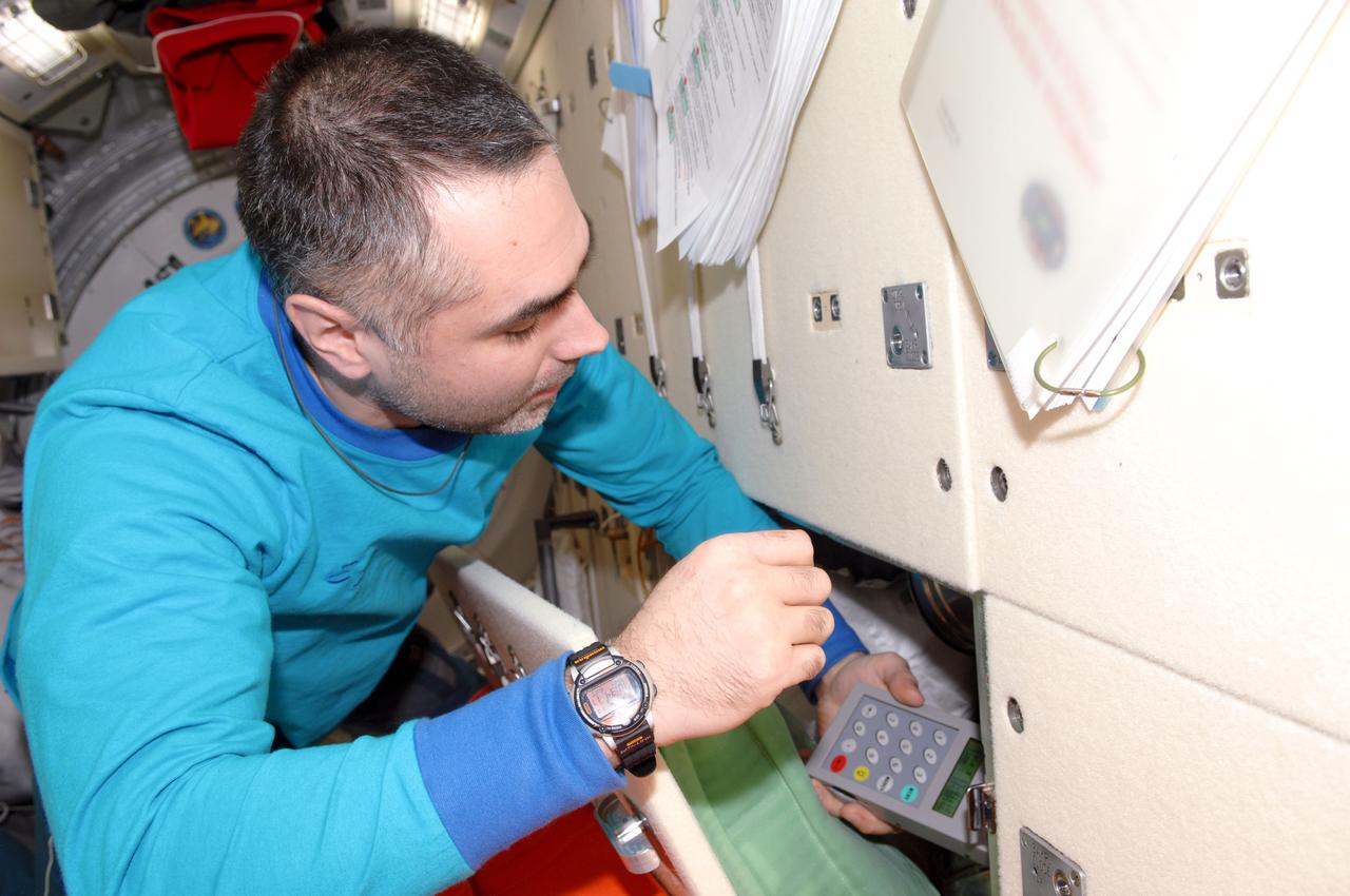
ISS034-E-021230 (10 Jan. 2013) --- Russian cosmonaut Evgeny Tarelkin, Expedition 34 flight engineer, uses the Liulin-5 Electronic Block behind a panel in the Rassvet Mini-Research Module 1 (MRM1) of the International Space Station.
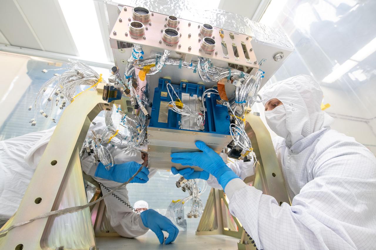
Mechanical technicians, Thomas Huber and Joseph Eddy, integrate an electronics box to the Ocean Color Instrument (OCI) flight deck in preparation for electrical connections and testing. OCI is a highly advanced optical spectrometer that will be used to measure properties of light over portions of the electromagnetic spectrum. It will enable continuous measurement of light at finer wavelength resolution than previous NASA satellite sensors, extending key system ocean color data records for climate studies. OCI is PACE's (Plankton, Aerosol, Cloud, ocean Ecosystem) primary sensor built at Goddard Space Flight Center in Greenbelt, MD.
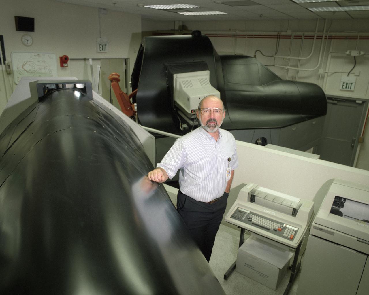
Electronics technician Joe Ciganek was responsible for operation and maintenance of the SR-71 simulator while it was at NASA's Dryden Flight Research Center.
Dan Raible, an Electronics Engineer in NASA Glenn Research Center’s Optics and Photonics Branch. Raible has a long history with NASA. Someone in his family has worked at what is now NASA Glenn Research since it was NACA. His grandfather, Four uncles and his father all supported space and aeronautics research.
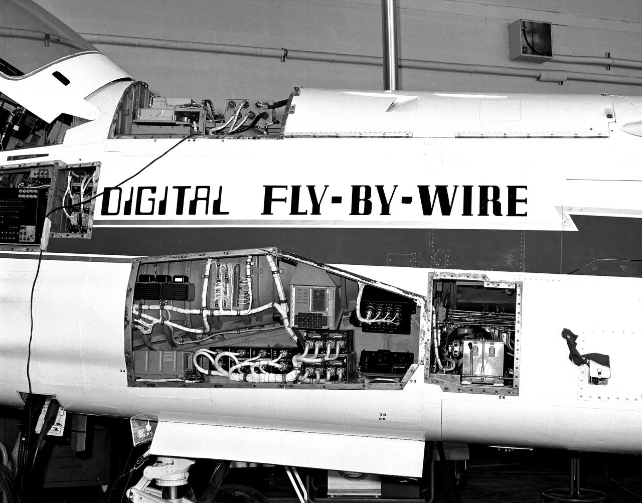
The Apollo hardware jammed into the F-8C. The computer is partially visible in the avionics bay at the top of the fuselage behind the cockpit. Note the display and keyboard unit in the gun bay. To carry the computers and other equipment, the F-8 DFBW team removed the aircraft's guns and ammunition boxes.

ISS003-E-5489 (August 2001) --- Cosmonaut Vladimir Dezhurov of Rosaviakosmos, Expedition Three flight engineer, works on electronic equipment behind a panel in the Zvezda Service Module. Please note: The date identifiers on some frames are not accurate due to a technical problem with one of the Expedition Three cameras. When a specific date is given in the text or description portion, it is correct.
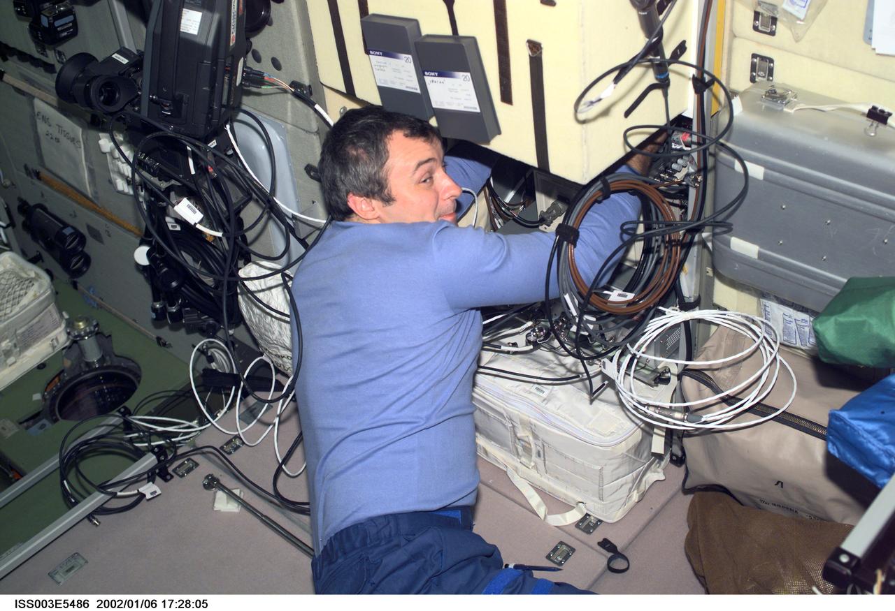
ISS003-E-5486 (August 2001) --- Cosmonaut Vladimir Dezhurov of Rosaviakosmos, Expedition Three flight engineer, works on electronic equipment behind a panel in the Zvezda Service Module. Please note: The date identifiers on some frames are not accurate due to a technical problem with one of the Expedition Three cameras. When a specific date is given in the text or description portion, it is correct.
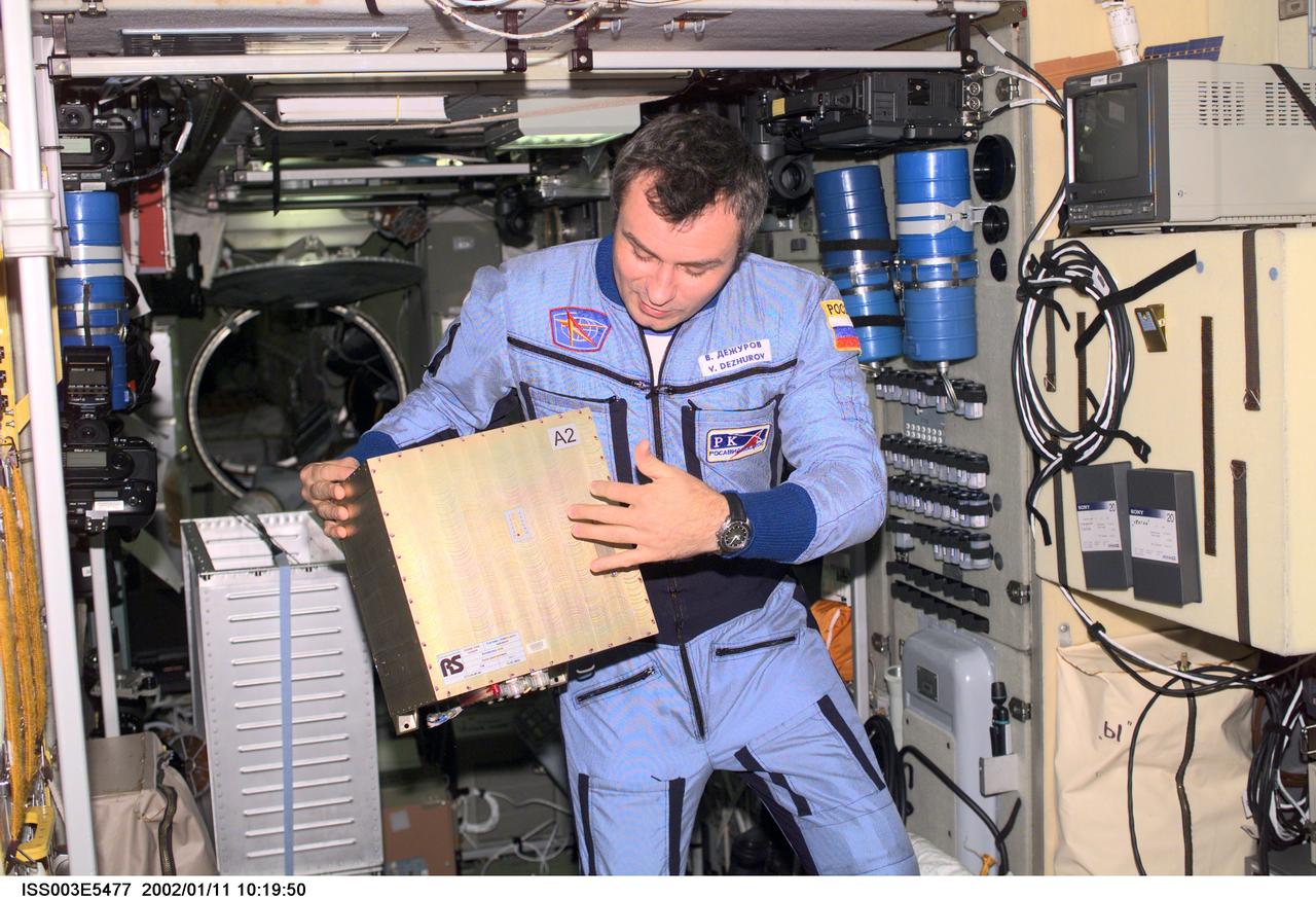
ISS003-E-5477 (August 2001) --- Cosmonaut Vladimir Dezhurov of Rosaviakosmos, Expedition Three flight engineer, holds a Global Time System (GTS) electronics unit in the Zvezda Service Module. Please note: The date identifiers on some frames are not accurate due to a technical problem with one of the Expedition Three cameras. When a specific date is given in the text or description portion, it is correct.

Michelle Sipe Exaros, with Lutron Electronics Co., is seen behind pamphlets and brochures of information during Energy Awareness Day at the Multi-Function Facility on Oct. 20. Every third Thursday of October, civil servants, contractors and several energy utilities promote the awareness of our sustainability goals at Kennedy Space Center and at home. Photo credit: Cory Huston

jsc2025e015690 (3/6/2025) --- An overview of the prototype with the various components as part of the High Performance Radiation Hardened GaN High Electron Mobility Transistors for Space Applications (Radiation Harden GaN) investigation which studies how radiation affects a type of transistor used in the semiconductor industry. Researchers measure the performance of the devices before, during, and after flight to determine whether performance degrades. This could help determine how well the transistors can tolerate radiation in space. Image courtesy of Department of Electrical and Computer Engineering, University of Delaware.

Shideh Naderi works on designing the electronics for the next generation Fiber Optic Sensing System.
This electron microscope image is a close-up of the center part of photo number S96-12301. http://photojournal.jpl.nasa.gov/catalog/PIA00284
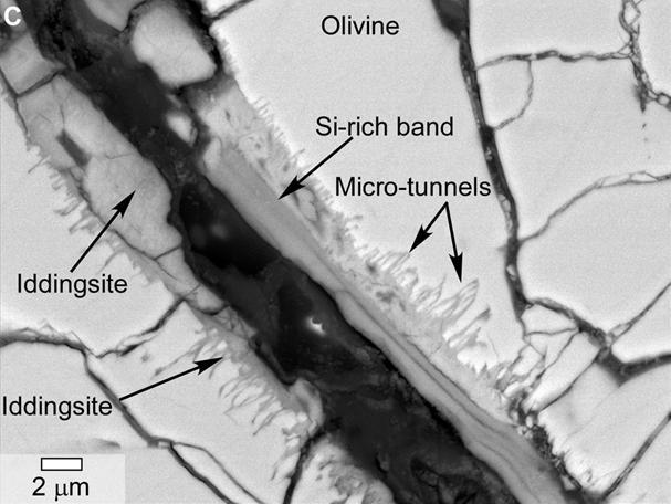
This scanning electron microscope image of a polished thin section of a meteorite from Mars shows tunnels and curved microtunnels.
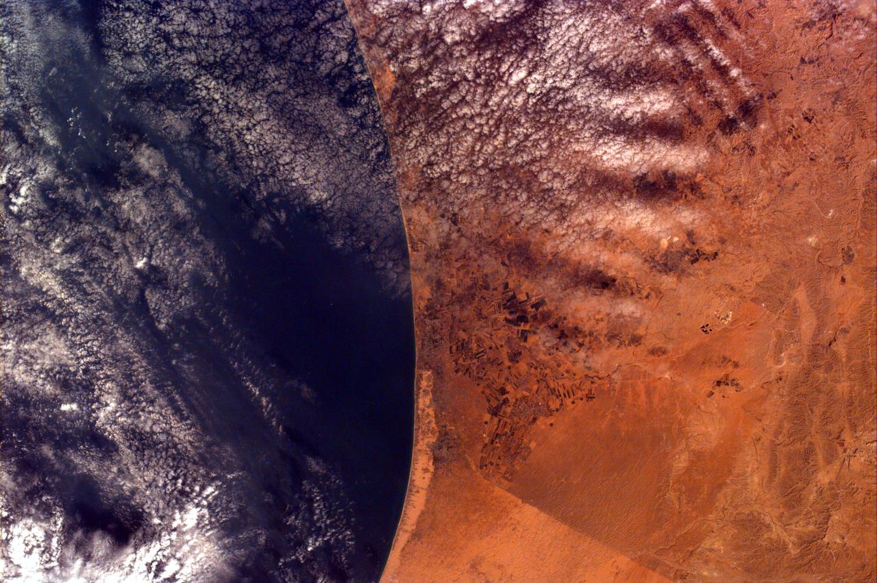
This image from NASA Kidsat electronic still camera was requested by Buist Academy for the purpose of studying the coast of Israel and the Mediterranean Sea.
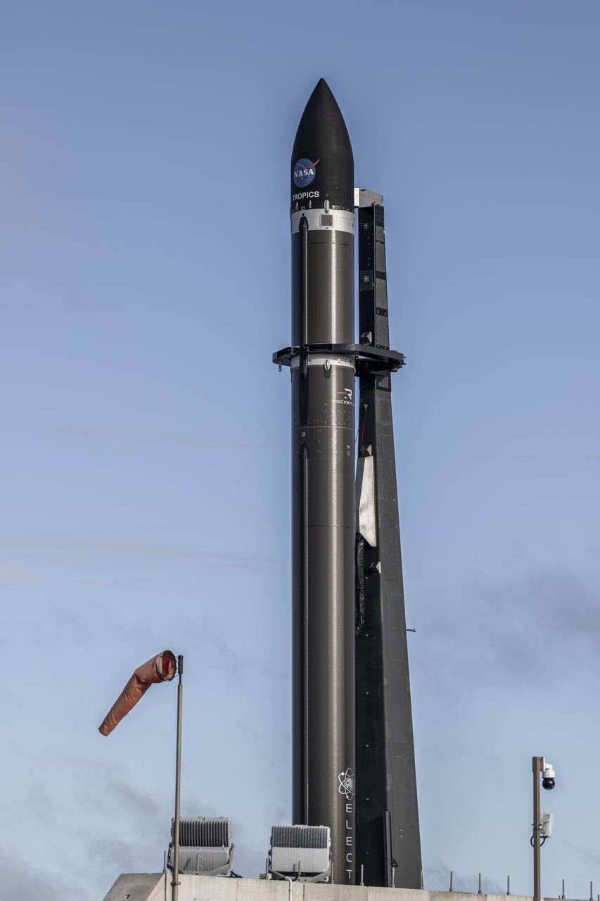
A Rocket Lab Electron rocket is poised for launch atop Pad B, Launch Complex 1, in Māhia, New Zealand. Launch time is May 8 at 1 p.m. New Zealand time (May 7 at 9 p.m. EDT). The Electron rocket is carrying two NASA CubeSats designed to study tropical cyclones, including hurricanes and typhoons. NASA’s Time-Resolved Observations of Precipitation structure and storm Intensity with a Constellation of Smallsats (TROPICS) CubeSats will provide data on temperature, precipitation, water vapor, and clouds by measuring microwave frequencies, providing insight into storm formation and intensification.
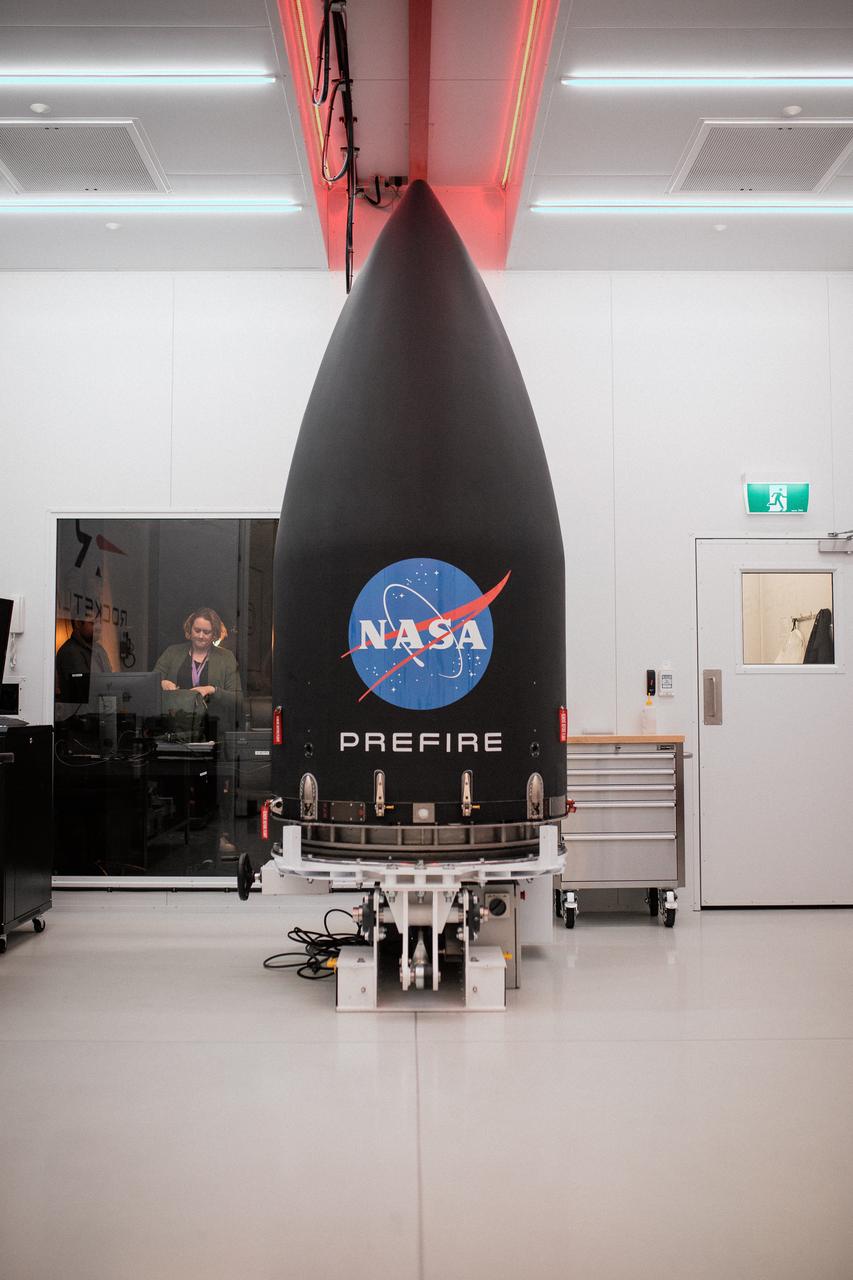
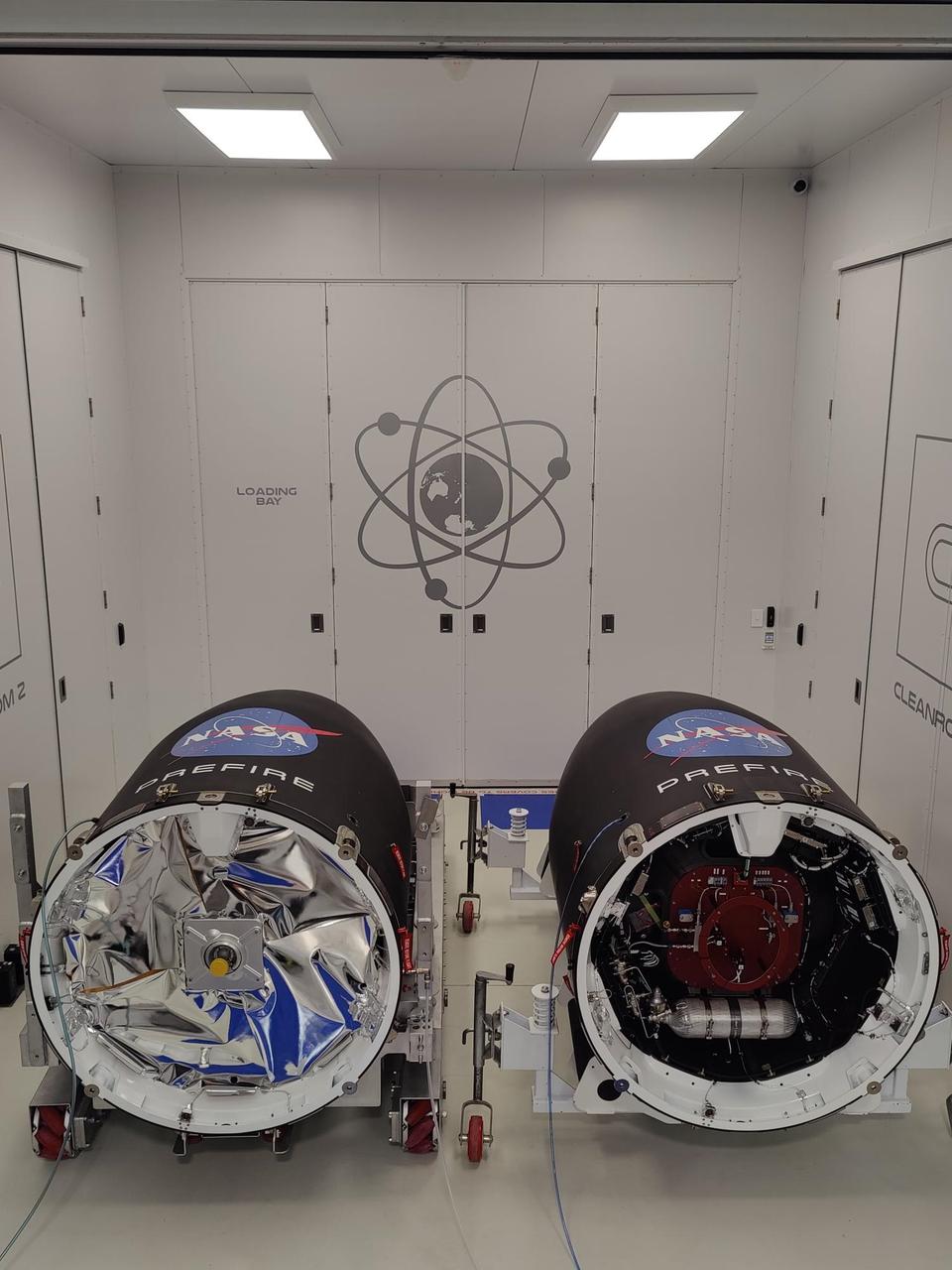
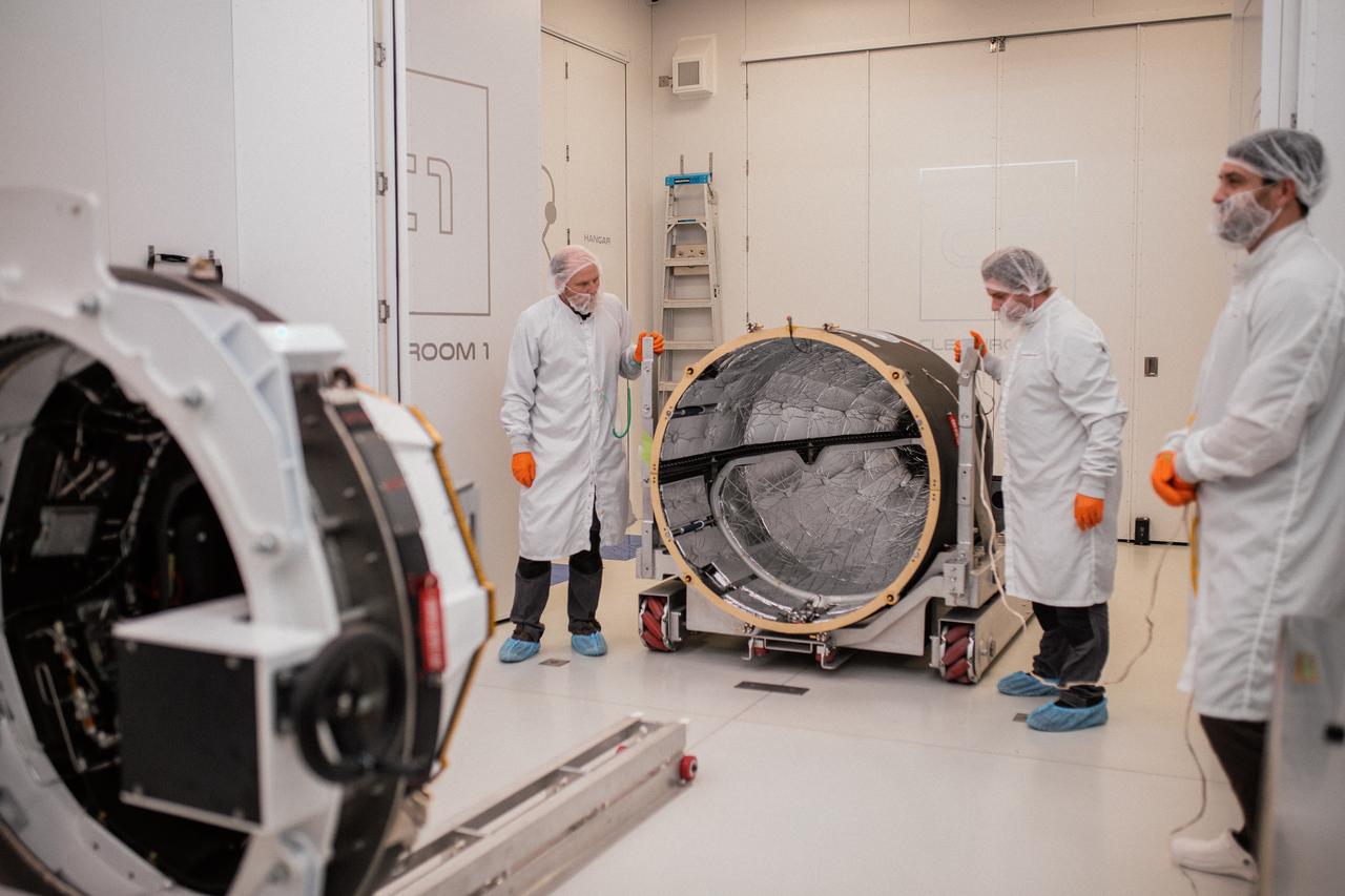
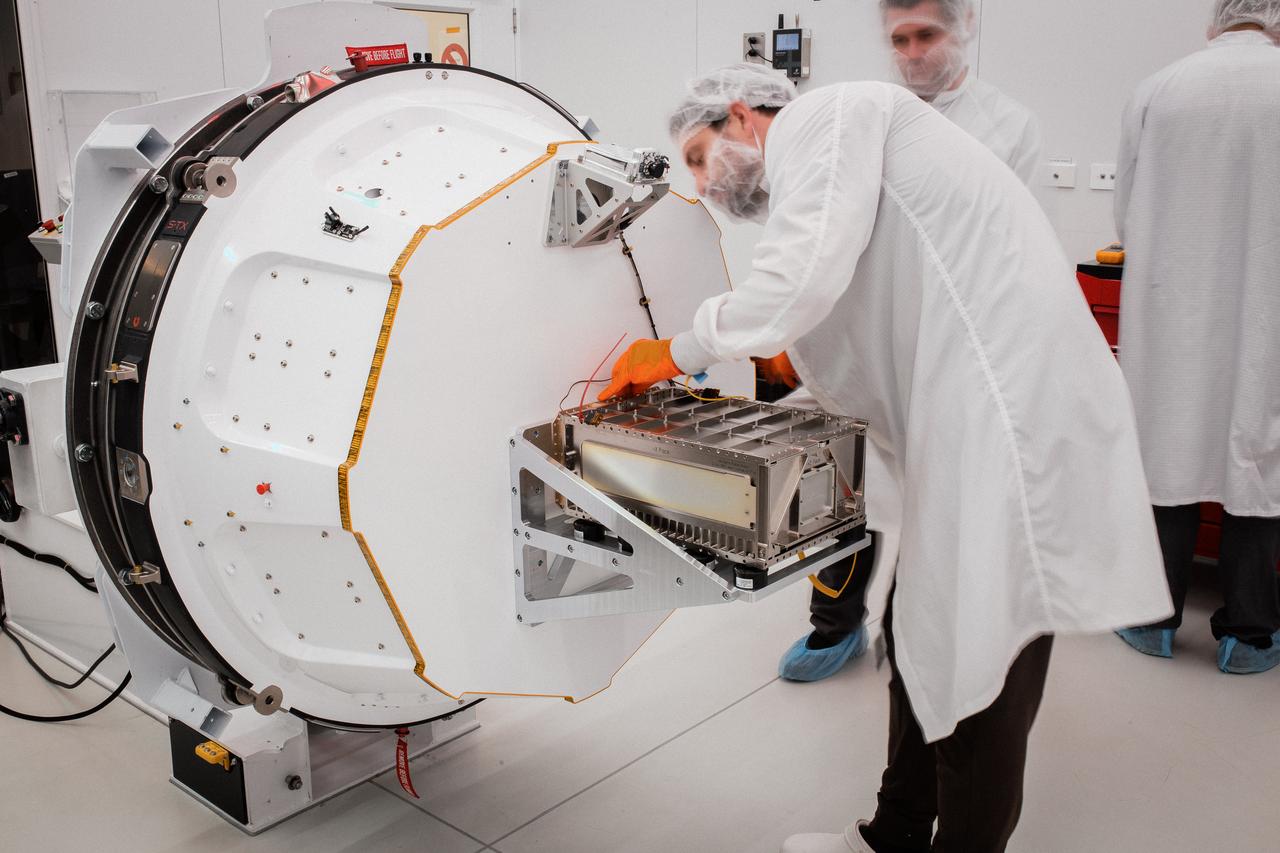
Technicians integrate NASA’s PREFIRE (Polar Radiant Energy in the Far-InfraRed Experiment) payload inside the Rocket Lab Electron rocket payload fairing on Wednesday, May 15, 2024, at the company’s facility in New Zealand. The agency’s PREFIRE mission to study heat loss to space in Earth’s polar regions will launch two CubeSats on two different flights aboard Rocket Lab's Electron rockets from the company’s Launch Complex 1 in Māhia, New Zealand.
Technicians integrate NASA’s PREFIRE (Polar Radiant Energy in the Far-InfraRed Experiment) payload inside the Rocket Lab Electron rocket payload fairing on Wednesday, May 15, 2024, at the company’s facility in New Zealand. The agency’s PREFIRE mission to study heat loss to space in Earth’s polar regions will launch two CubeSats on two different flights aboard Rocket Lab's Electron rockets from the company’s Launch Complex 1 in Māhia, New Zealand.
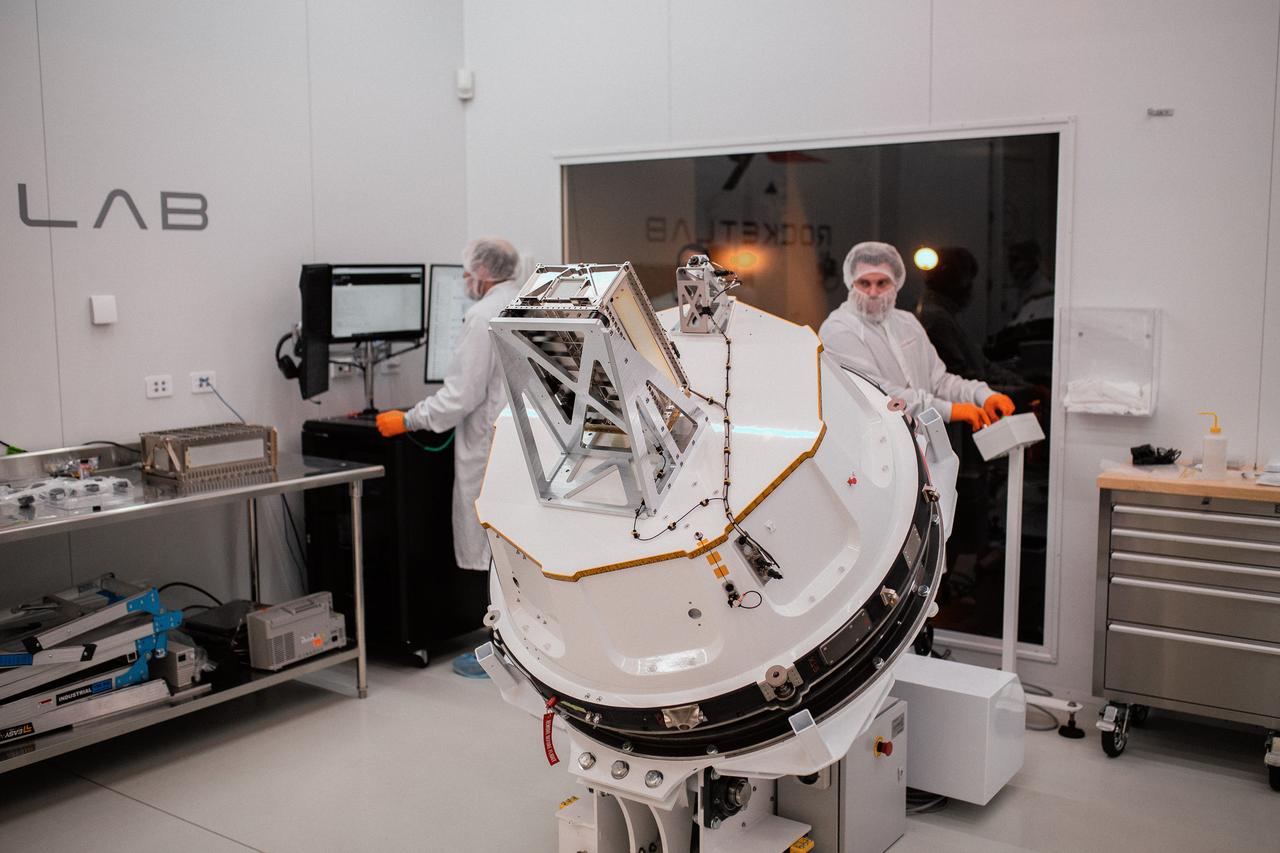
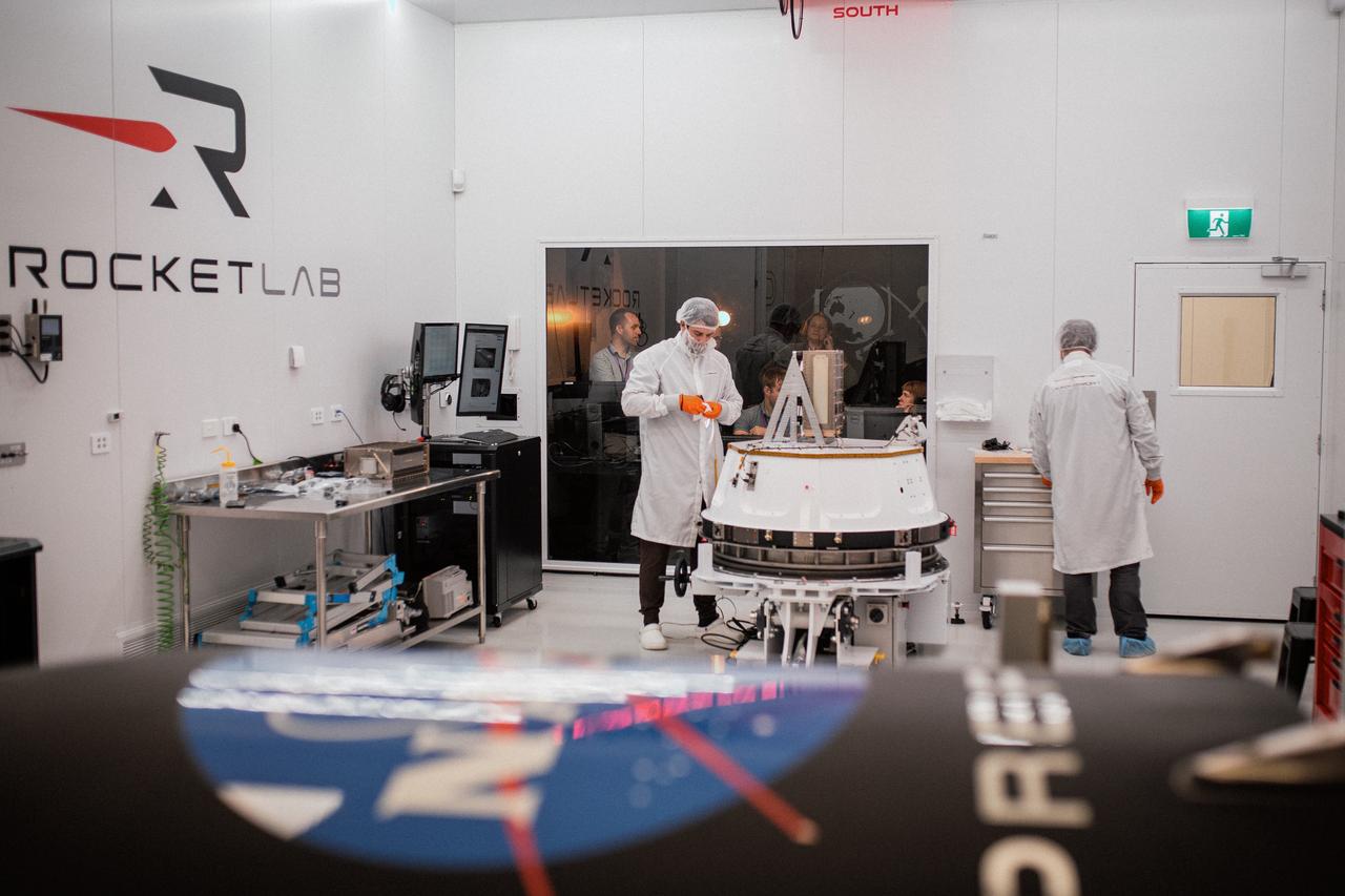
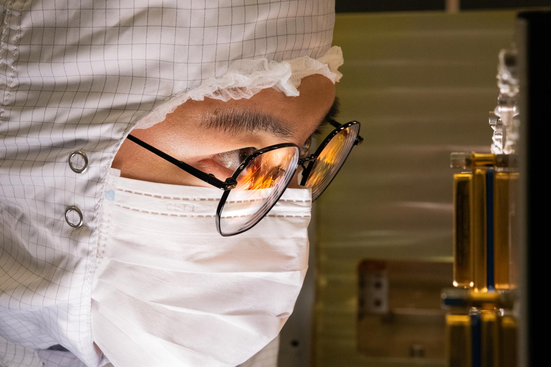
Technicians process NASA’s PREFIRE (Polar Radiant Energy in the Far-InfraRed Experiment) ahead of integration with a Rocket Lab Electron rocket on Thursday, May 2, 2024, at the company’s facility in New Zealand. The agency’s PREFIRE mission to study heat loss to space in Earth’s polar regions will launch two CubeSats on two different flights aboard Rocket Lab's Electron rockets from the company’s Launch Complex 1 in Māhia, New Zealand.

Technicians integrate NASA’s PREFIRE (Polar Radiant Energy in the Far-InfraRed Experiment) payload inside the Rocket Lab Electron rocket payload fairing on Wednesday, May 15, 2024, at the company’s facility in New Zealand. The agency’s PREFIRE mission to study heat loss to space in Earth’s polar regions will launch two CubeSats on two different flights aboard Rocket Lab's Electron rockets from the company’s Launch Complex 1 in Māhia, New Zealand.
Technicians integrate NASA’s PREFIRE (Polar Radiant Energy in the Far-InfraRed Experiment) payload inside the Rocket Lab Electron rocket payload fairing on Wednesday, May 15, 2024, at the company’s facility in New Zealand. The agency’s PREFIRE mission to study heat loss to space in Earth’s polar regions will launch two CubeSats on two different flights aboard Rocket Lab's Electron rockets from the company’s Launch Complex 1 in Māhia, New Zealand.
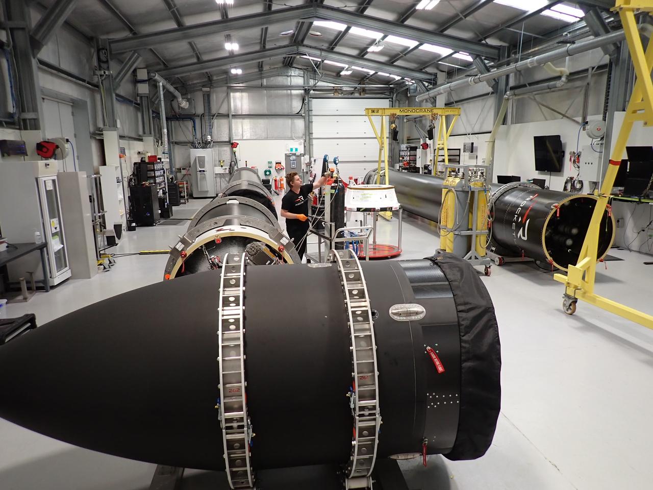
NASA’s PREFIRE (Polar Radiant Energy in the Far-InfraRed Experiment) CubeSats are encapsulated inside Rocket Lab Electron rocket payload fairings on Tuesday, May 21, 2024, at the company’s facility in New Zealand. The agency’s PREFIRE mission to study heat loss to space in Earth’s polar regions will launch two CubeSats on two different flights aboard Rocket Lab's Electron rockets from the company’s Launch Complex 1 in Māhia, New Zealand.

Technicians integrate NASA’s PREFIRE (Polar Radiant Energy in the Far-InfraRed Experiment) payload inside the Rocket Lab Electron rocket payload fairing on Wednesday, May 15, 2024, at the company’s facility in New Zealand. The agency’s PREFIRE mission to study heat loss to space in Earth’s polar regions will launch two CubeSats on two different flights aboard Rocket Lab's Electron rockets from the company’s Launch Complex 1 in Māhia, New Zealand.
Technicians integrate NASA’s PREFIRE (Polar Radiant Energy in the Far-InfraRed Experiment) payload inside the Rocket Lab Electron rocket payload fairing on Wednesday, May 15, 2024, at the company’s facility in New Zealand. The agency’s PREFIRE mission to study heat loss to space in Earth’s polar regions will launch two CubeSats on two different flights aboard Rocket Lab's Electron rockets from the company’s Launch Complex 1 in Māhia, New Zealand.
Technicians integrate NASA’s PREFIRE (Polar Radiant Energy in the Far-InfraRed Experiment) payload inside the Rocket Lab Electron rocket payload fairing on Wednesday, May 15, 2024, at the company’s facility in New Zealand. The agency’s PREFIRE mission to study heat loss to space in Earth’s polar regions will launch two CubeSats on two different flights aboard Rocket Lab's Electron rockets from the company’s Launch Complex 1 in Māhia, New Zealand.
OSAM-1 electronics engineer, Sam Zhao, peers inside the robotic electronics unit inside the cleanroom at Goddard Space Flight Center, Greenbelt, Md., Oct 8, 2024. This photo has been approved for public release by OSAM-1 project management and Nasa Export Control. NASA/Mike Guinto
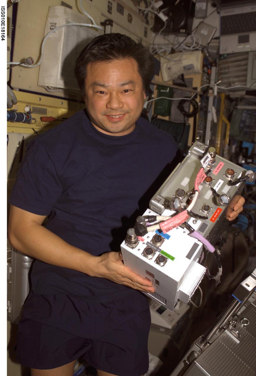
ISS010-E-18164 (17 February 2005) --- Astronaut Leroy Chiao, Expedition 10 commander and NASA ISS science officer, holds an Electronic Box Assembly, and Violation Isolation and Stabilization (VIS) Controller Assembly, which is part of the Treadmill Vibration Isolation System (TVIS) in the Zvezda Service Module of the International Space Station (ISS). Also in view is a VIS/TM data cable and VIS/TM power cable. This box receives power and distributes it between the treadmill and the VIS subassemblies.
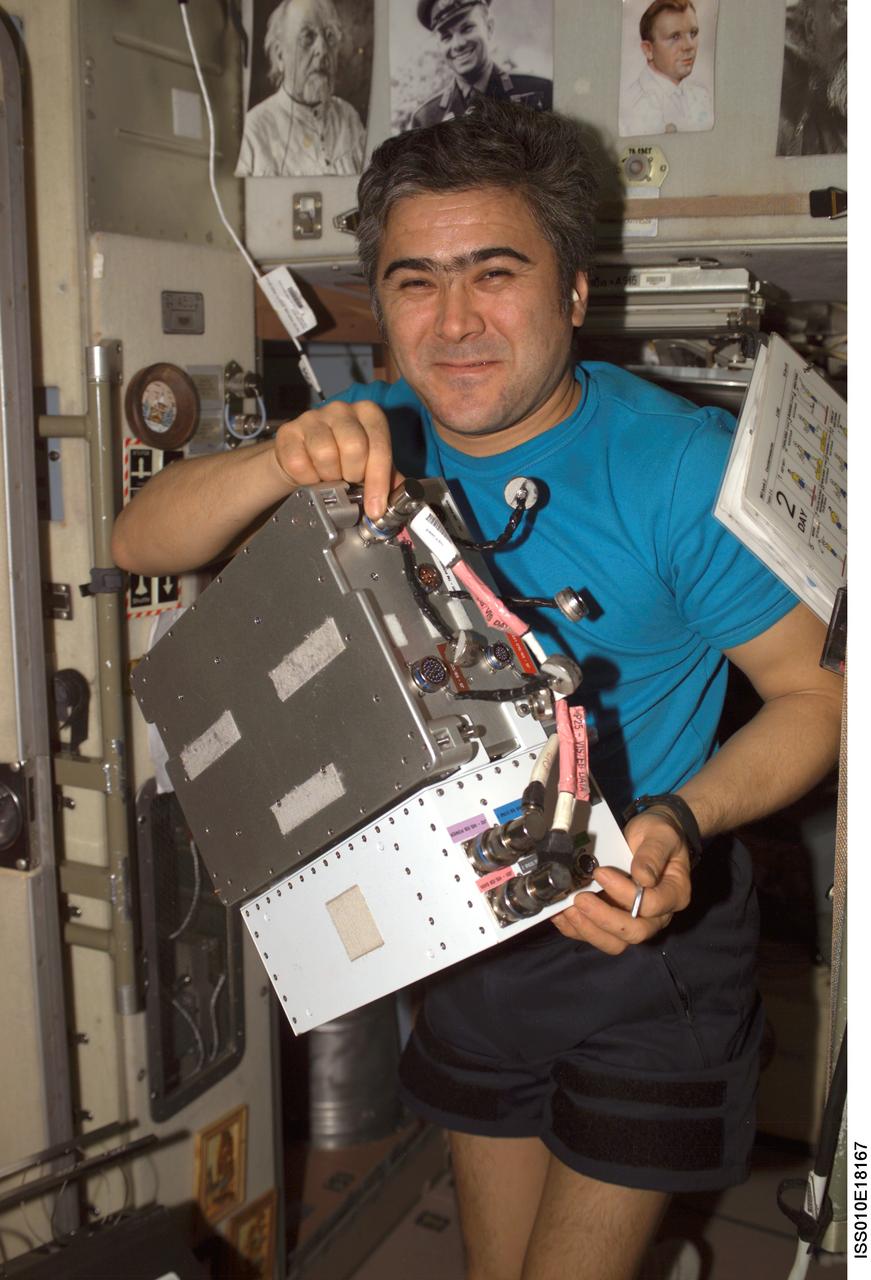
ISS010-E-18167 (17 February 2005) --- Cosmonaut Salizhan S. Sharipov, Expedition 10 flight engineer representing Russia's Federal Space Agency, holds an Electronic Box Assembly, and Violation Isolation and Stabilization (VIS) Controller Assembly, which is part of the Treadmill Vibration Isolation System (TVIS) in the Zvezda Service Module of the International Space Station (ISS). Also in view is a VIS/TM data cable and VIS/TM power cable. This box receives power and distributes it between the treadmill and the VIS subassemblies.
Technicians install components that will aid with guidance, navigation and control of NASA Juno spacecraft.
This scanning electron microscope image shows speroidal features embedded in a layer of iddingsite, a mineral formed by action of water, in a meteorite that came from Mars.

A Rocket Lab Electron rocket lifts off Launch Complex 1, Pad B, in Māhia, New Zealand on May 8 at 1 p.m. New Zealand time (May 7 at 9 p.m. EDT), carrying two NASA CubeSats designed to study tropical cyclones, including hurricanes and typhoons. NASA’s Time-Resolved Observations of Precipitation structure and storm Intensity with a Constellation of Smallsats (TROPICS) CubeSats will provide data on temperature, precipitation, water vapor, and clouds by measuring microwave frequencies, providing insight into storm formation and intensification.
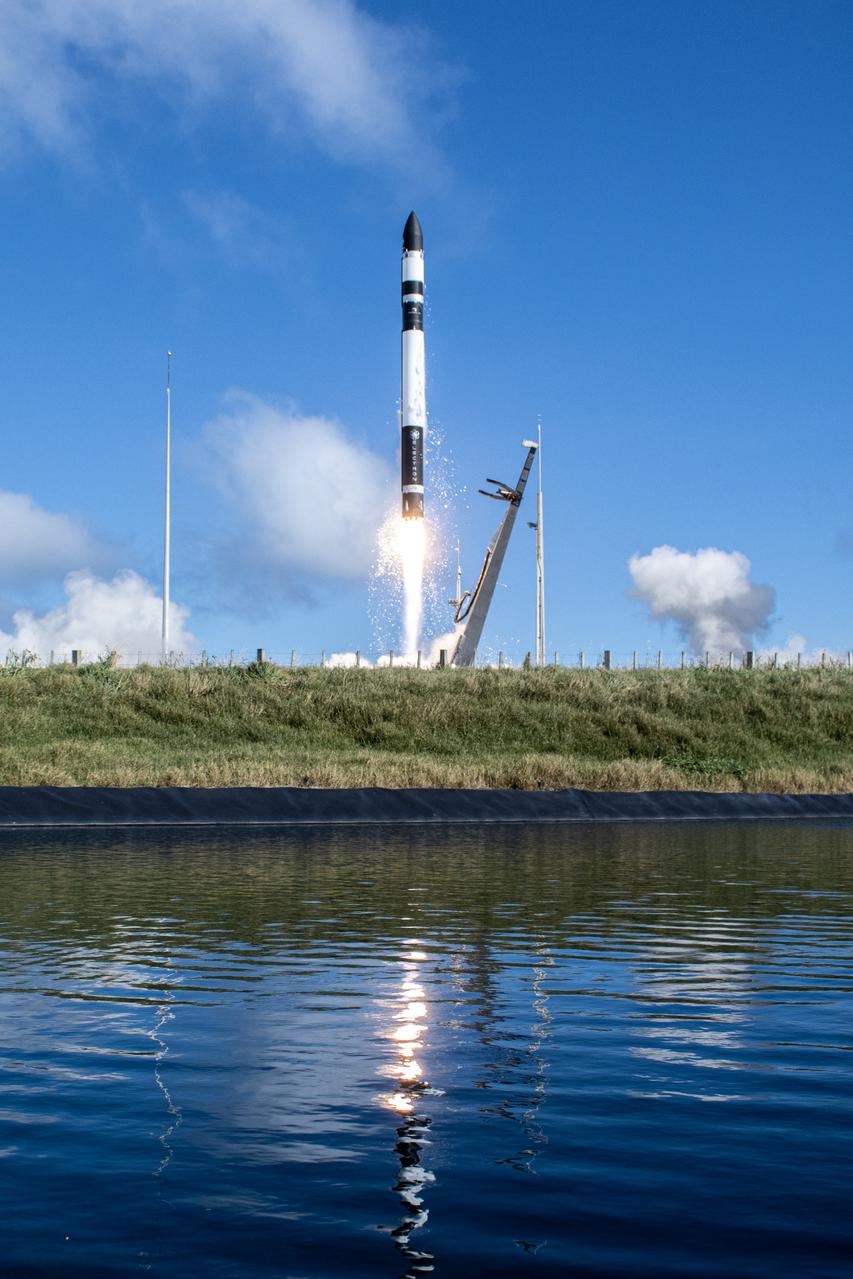
A Rocket Lab Electron rocket lifts off Launch Complex 1, Pad B, in Māhia, New Zealand on May 8 at 1 p.m. New Zealand time (May 7 at 9 p.m. EDT), carrying two NASA CubeSats designed to study tropical cyclones, including hurricanes and typhoons. NASA’s Time-Resolved Observations of Precipitation structure and storm Intensity with a Constellation of Smallsats (TROPICS) CubeSats will provide data on temperature, precipitation, water vapor, and clouds by measuring microwave frequencies, providing insight into storm formation and intensification.
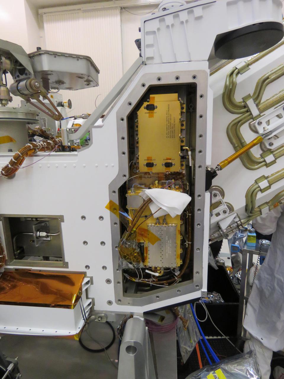
This image, taken in the clean room at NASA's Jet Propulsion Laboratory in Southern California, shows the Radar Imager for Mars' Subsurface Experiment (RIMFAX) electronic's box after it has been inserted into the Perseverance rover. The gold-plated electronics box is at the top of the opening. RIMFAX's antenna will be mounted on the bottom rear of the rover. https://photojournal.jpl.nasa.gov/catalog/PIA24204
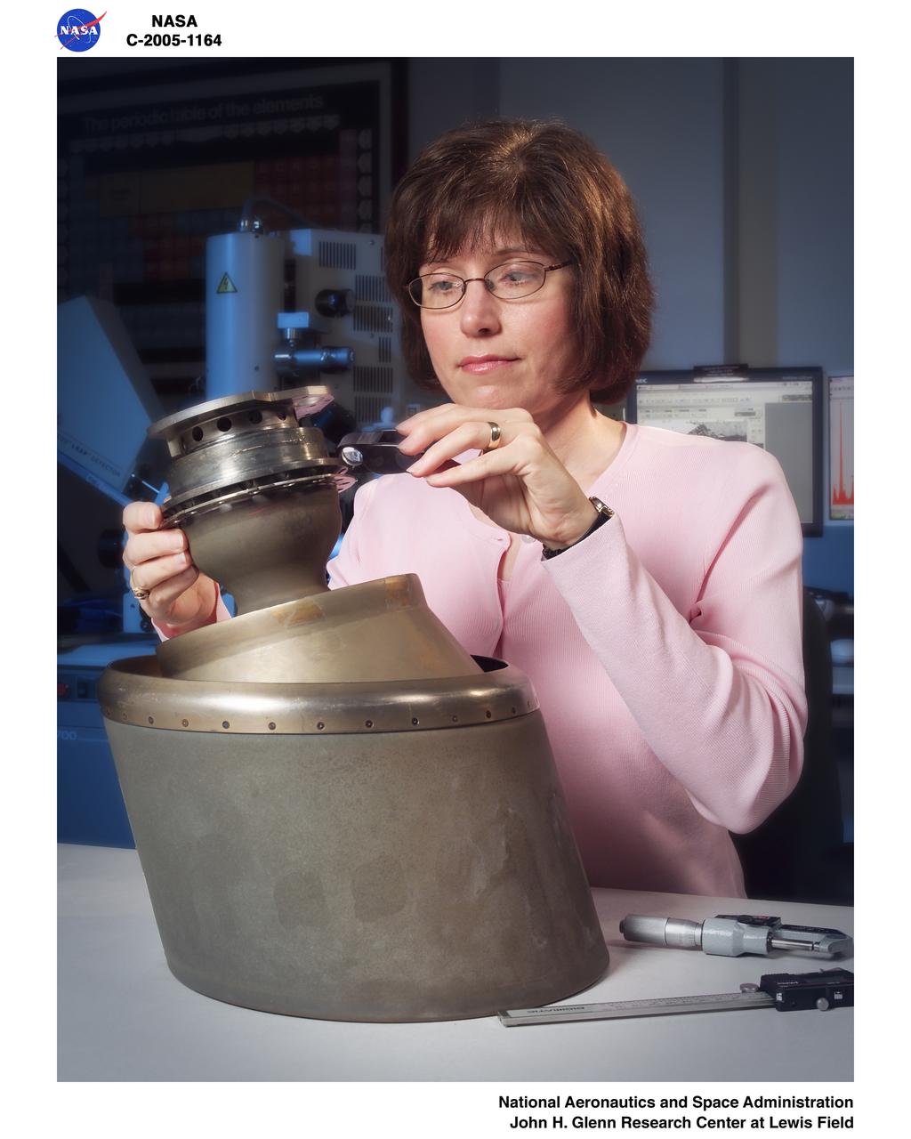
Reaction Control System Thruster examined in the electron optics lab Near Field Emission Scanning Electron Microscope

Reeves Electronic analog computer (REAC), Ames' first electronic computing machine, was acquired in 1949 to perform control simulation analysis.
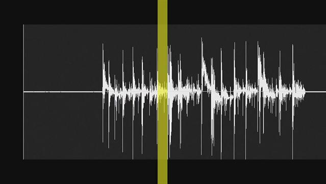
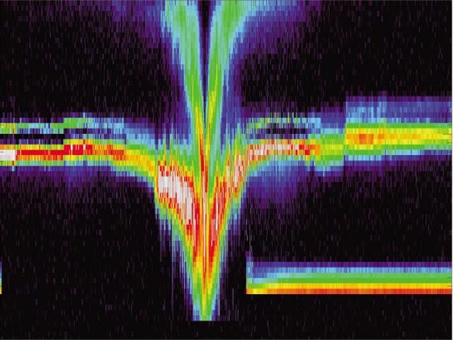
This video demonstrates the hiss-like radio noise generated by electrons moving along magnetic field lines from the Saturnian moon Enceladus to a glowing patch of ultraviolet light on Saturn.
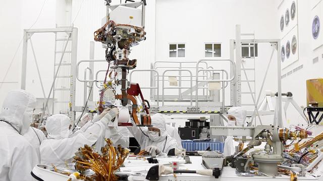
In the clean room at NASA Jet Propulsion Laboratory, engineers gather around the base of Curiosity neck the Mast as they slowly lower it into place for attachment to the rover body the Wet Electronics Box, or WEB.
Over 1300 energy spectra taken on September 22, 2001 from the ion and electron instruments on NASA Deep Space 1 span a region of 1,400,000 kilometers 870,000 miles centered on the closest approach to the nucleus of comet Borrelly.

Three of NASA contributions to the ESA Rosetta mission are pictured here: an ultraviolet spectrometer called Alice top, the Ion and Electron Sensor IES bottom left, and the Microwave Instrument for Rosetta Orbiter MIRO bottom right.
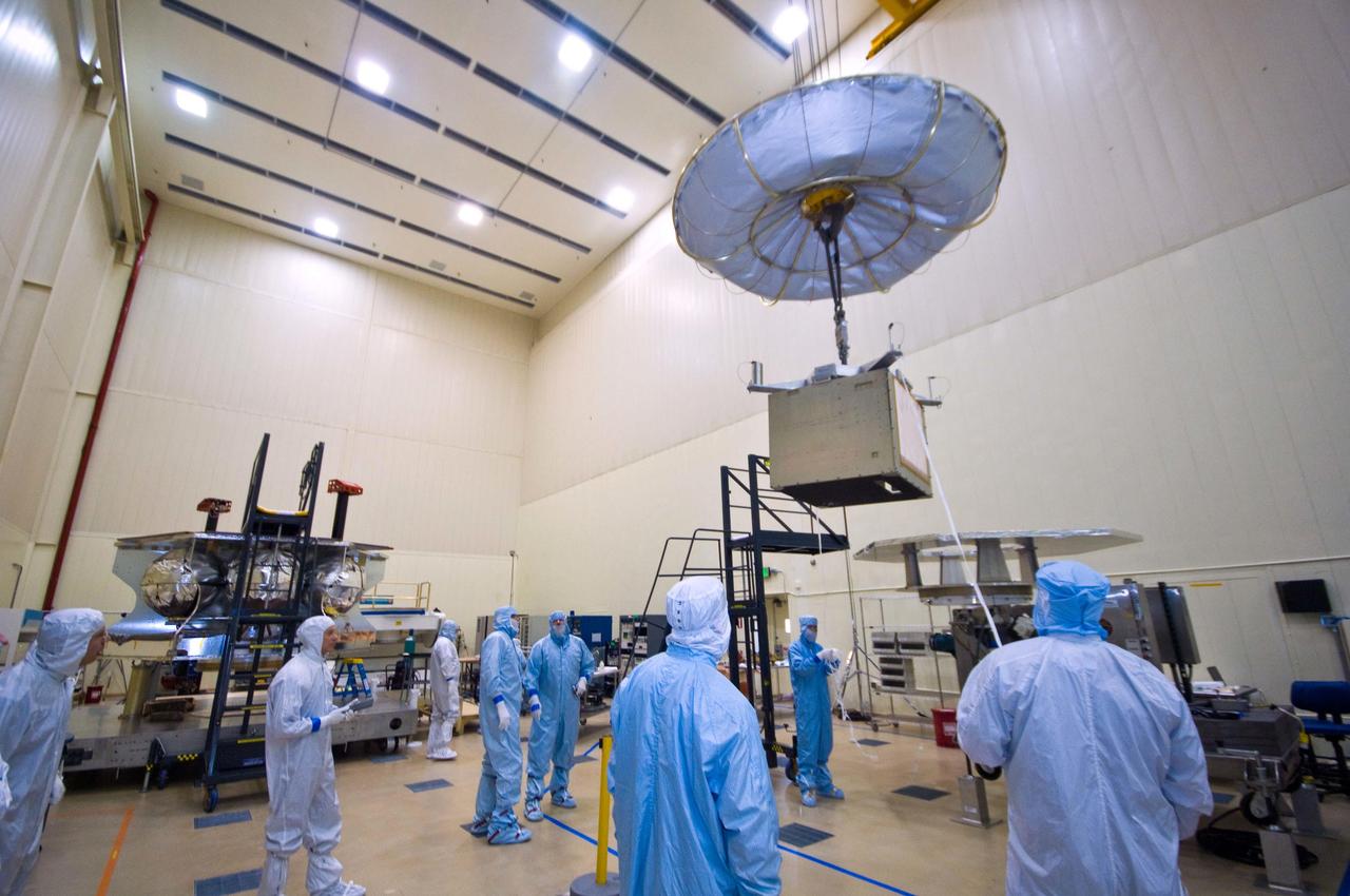
Assembly began April 1, 2010, for NASA Juno spacecraft. Workers at Lockheed Martin Space Systems in Denver, Colorado are moving into place the vault that will protect the spacecraft sensitive electronics from Jupiter intense radiation belts.
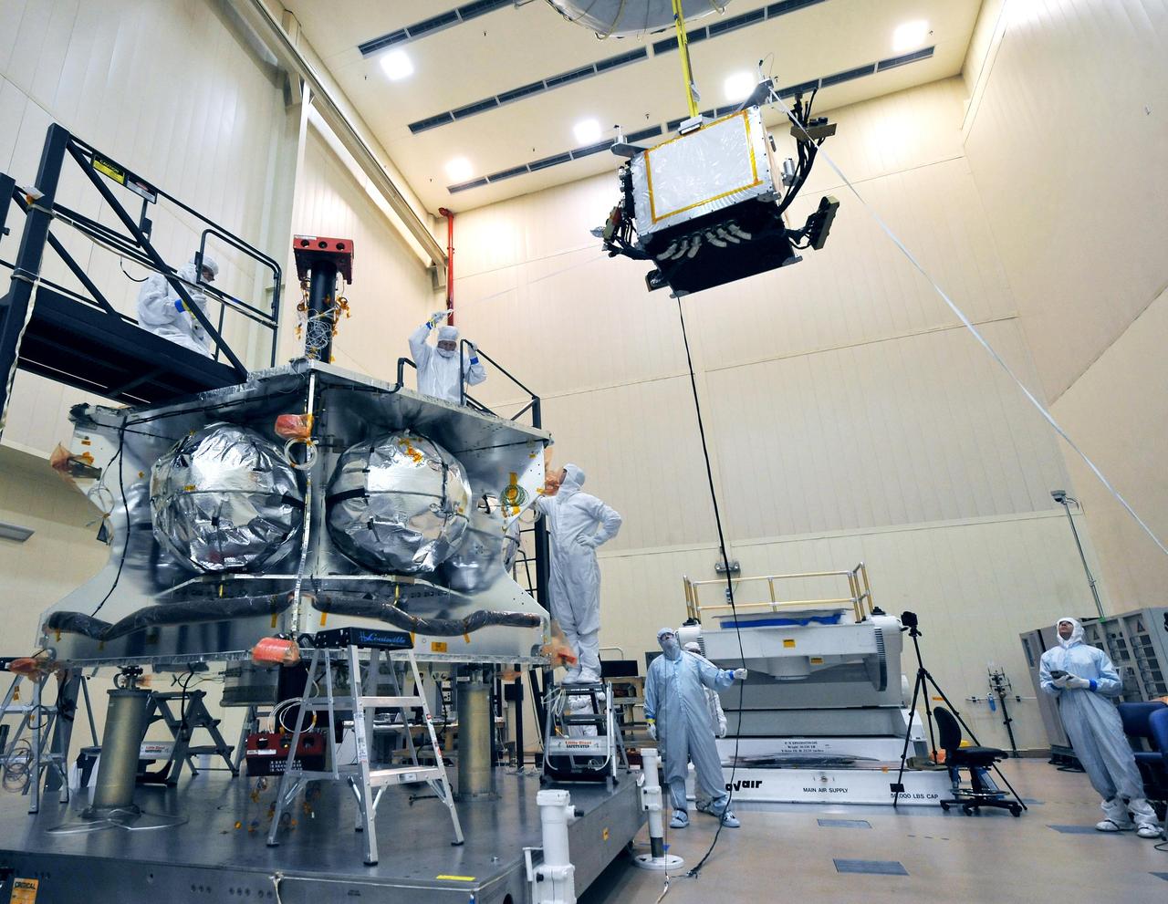
Technicians lowered a special radiation vault onto the propulsion module of NASA Juno spacecraft. The vault will dramatically slow the aging effect radiation has on the electronics for the duration of the mission.
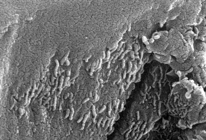
This electron microscope image shows extremely tiny tubular structures that are possible microscopic fossils of bacteria-like organisms that may have lived on Mars more than 3.6 billion years ago. http://photojournal.jpl.nasa.gov/catalog/PIA00285