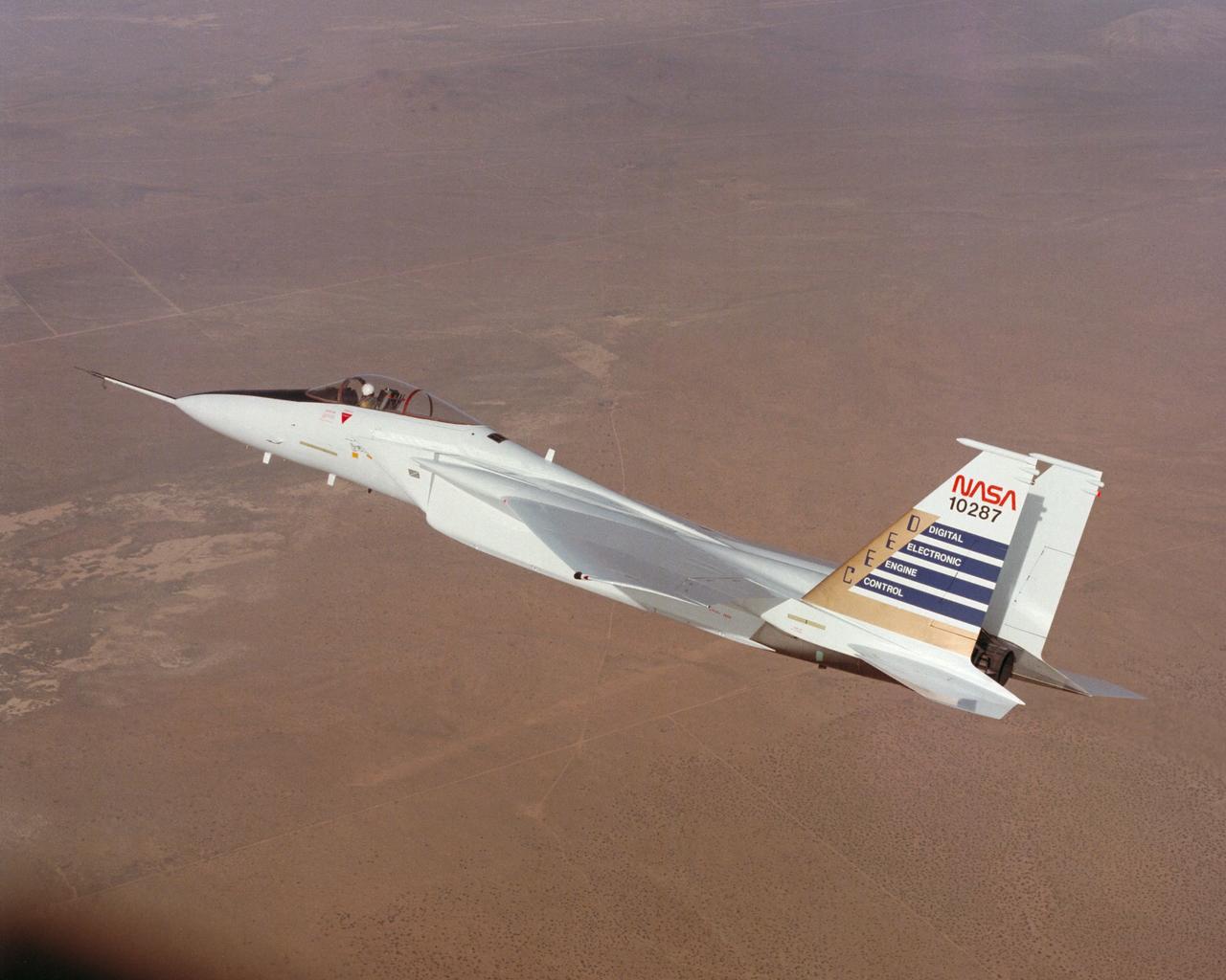
Digital Electronic Engine Control F-15A #287 in flight.
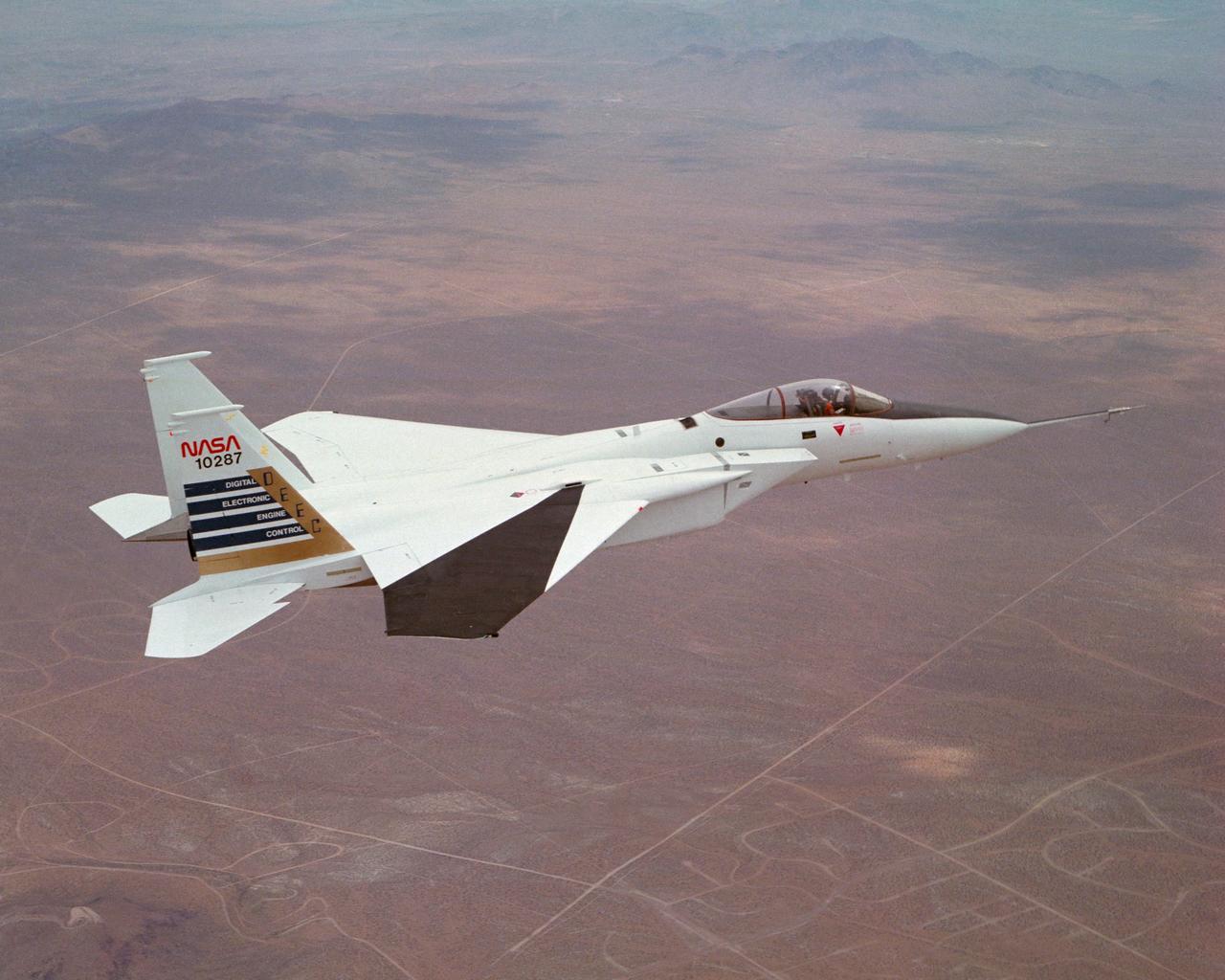
Digital Electronic Engine Control F-15A #287 in flight over California City. Note wing deflection measurement system on right wing.

Engineers at NASA's Jet Propulsion Laboratory – from left, Brandon Creager, Juan Gloria, Joshua Nachtigal, and Sonny Gutierrez – are shown assembling the electronics palette for the Coronagraph Instrument on NASA's Roman Space Telescope in December 2022. One of two main sections of the instrument, this layer houses the instrument electronics that receive instructions from the Roman spacecraft and send back the Coronagraph Instrument's scientific data. The electronics also control the mechanical components on the optical bench and the instrument heaters. https://photojournal.jpl.nasa.gov/catalog/PIA25435
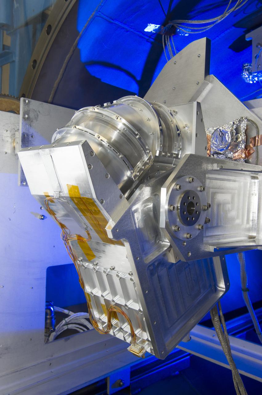
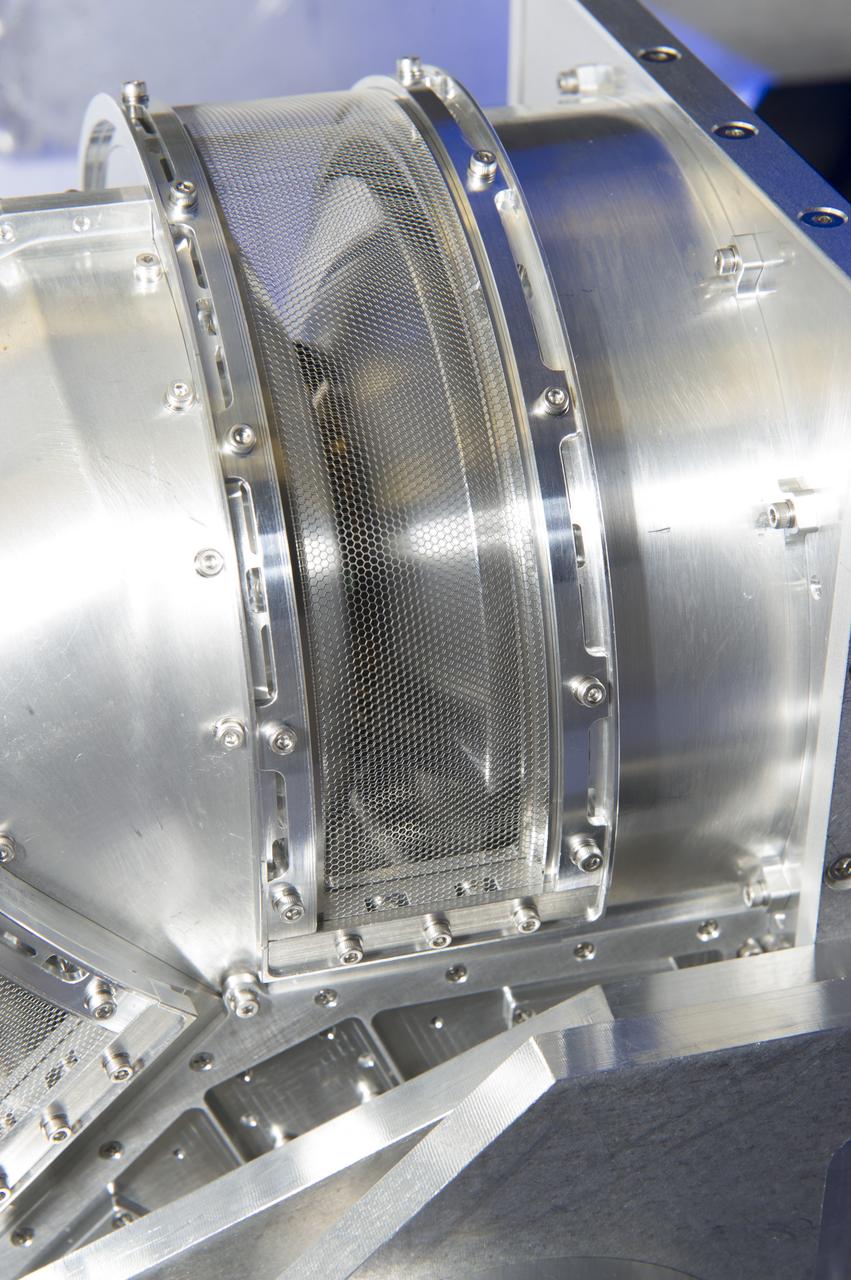
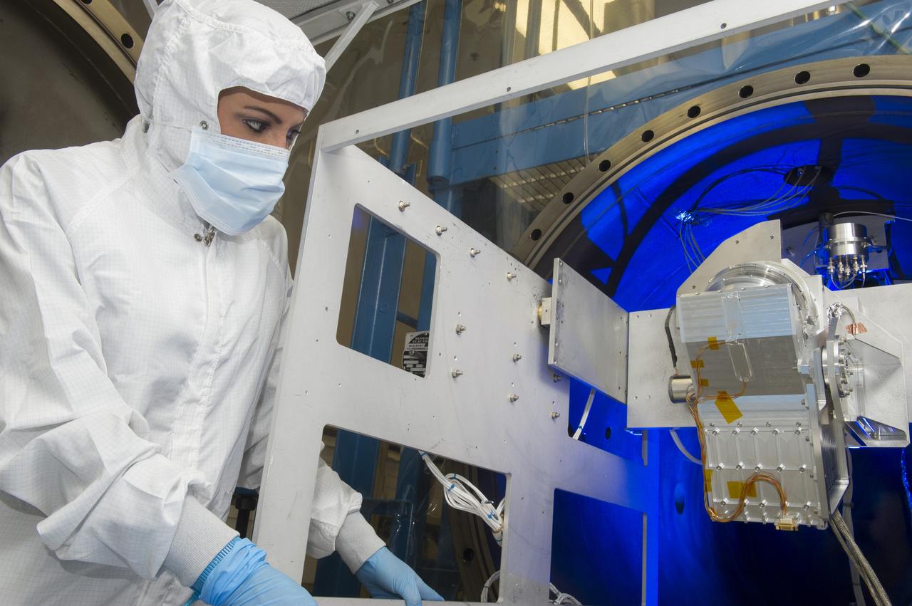
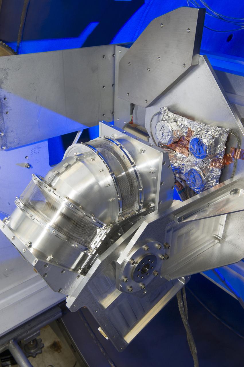
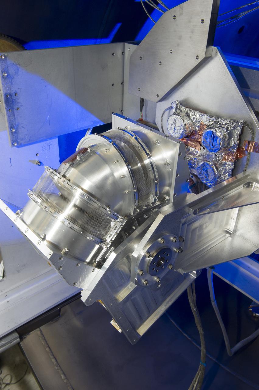
DUAL ION SPECTROMETER (DIS) ENGINEERING TEST UNIT (ETU) AT THE LOW ENERGY ELECTRON AND ION FACILITY (LEEIF), NSSTC
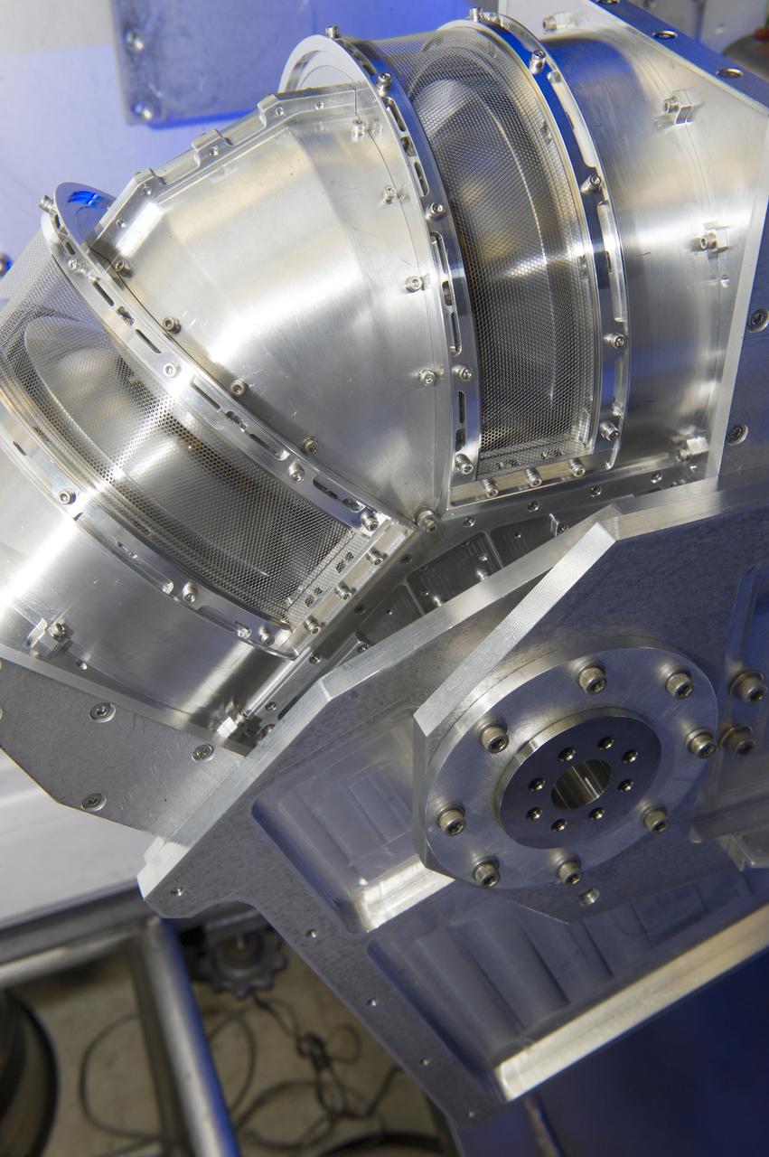
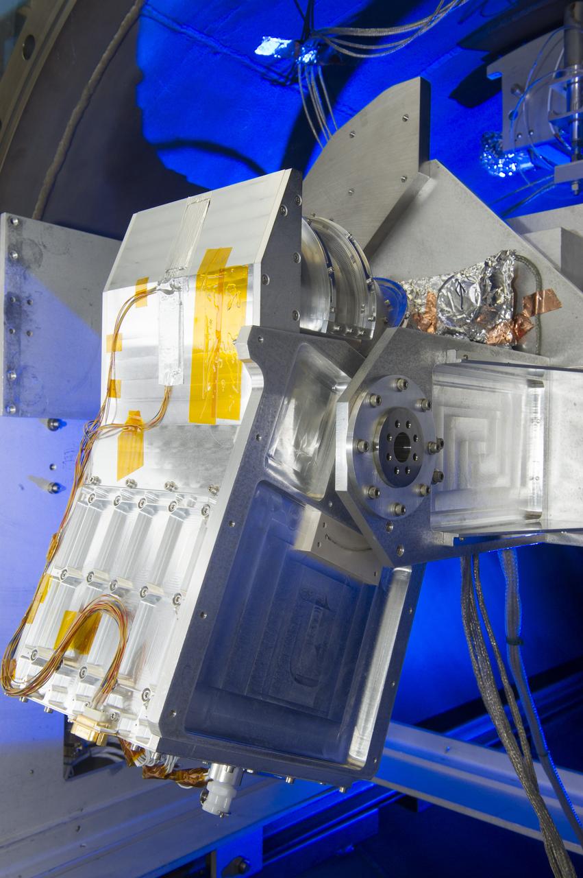
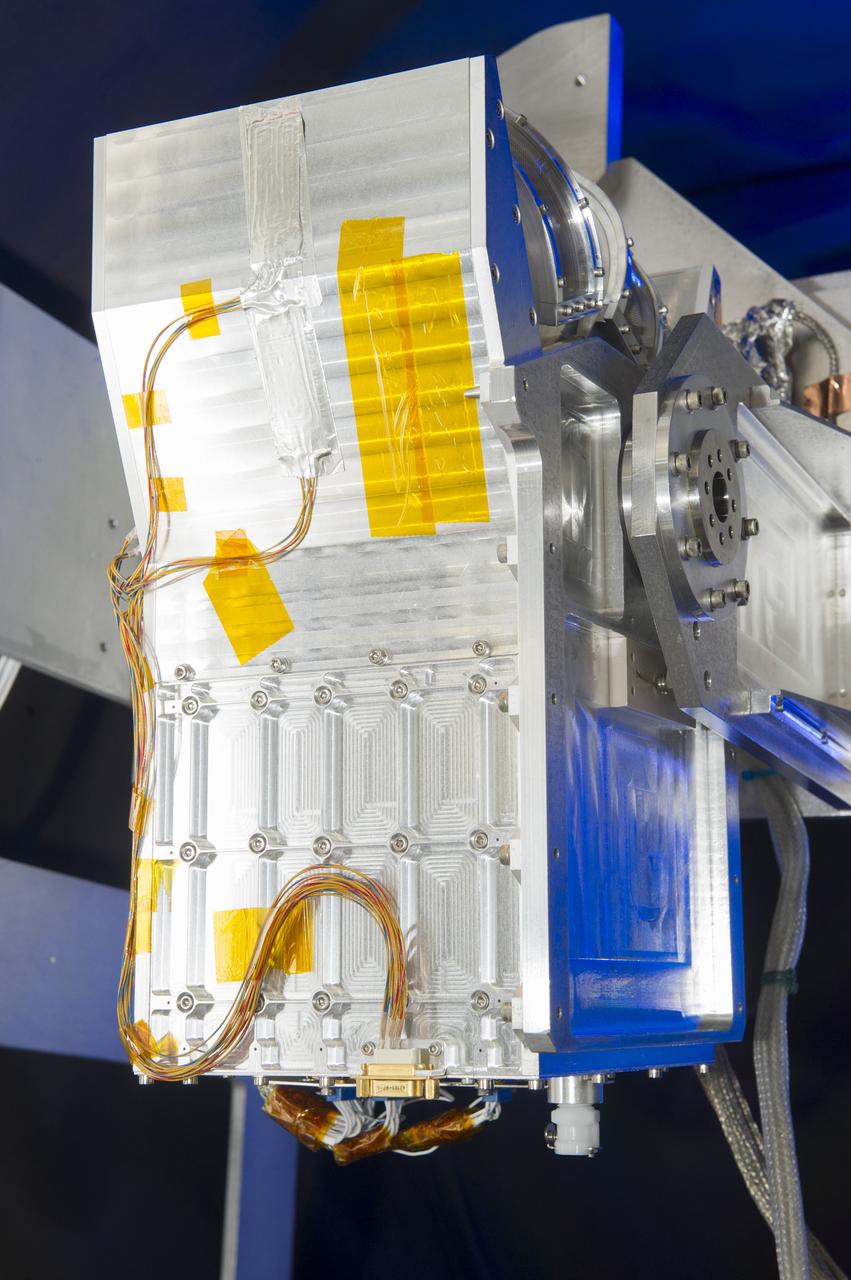
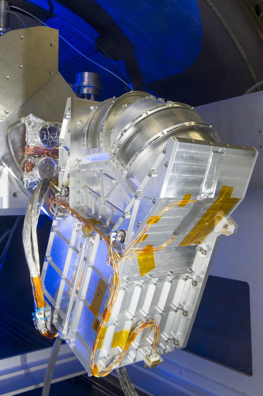
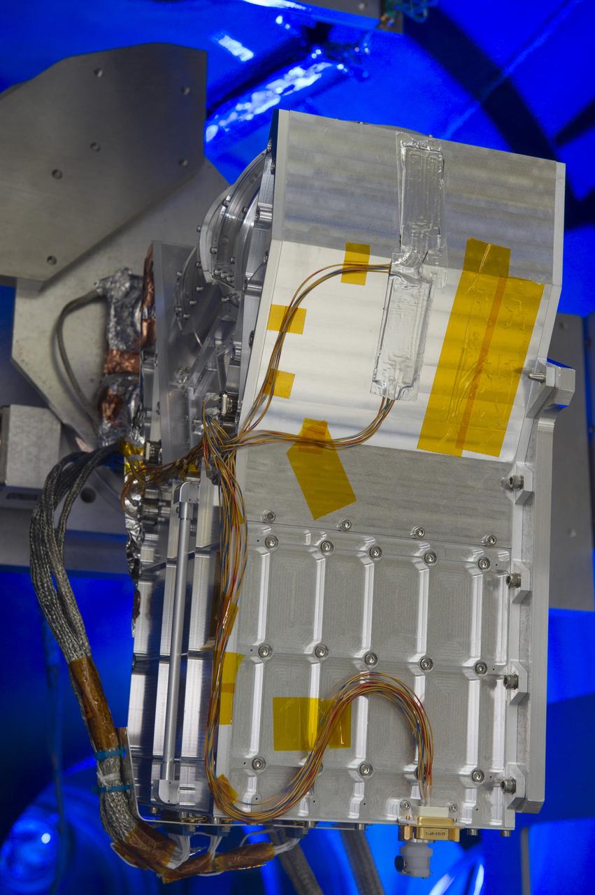
DUAL ION SPECTROMETER (DIS) ENGINEERING TEST UNIT (ETU) AT THE LOW ENERGY ELECTRON AND ION FACILITY (LEEIF), NSSTC
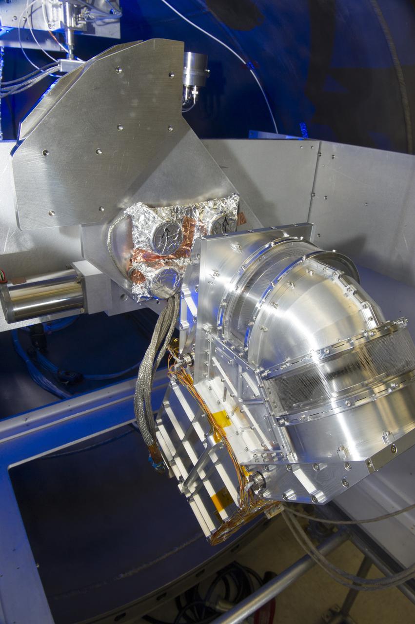
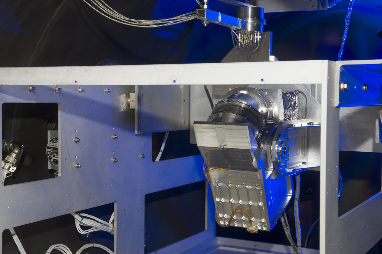
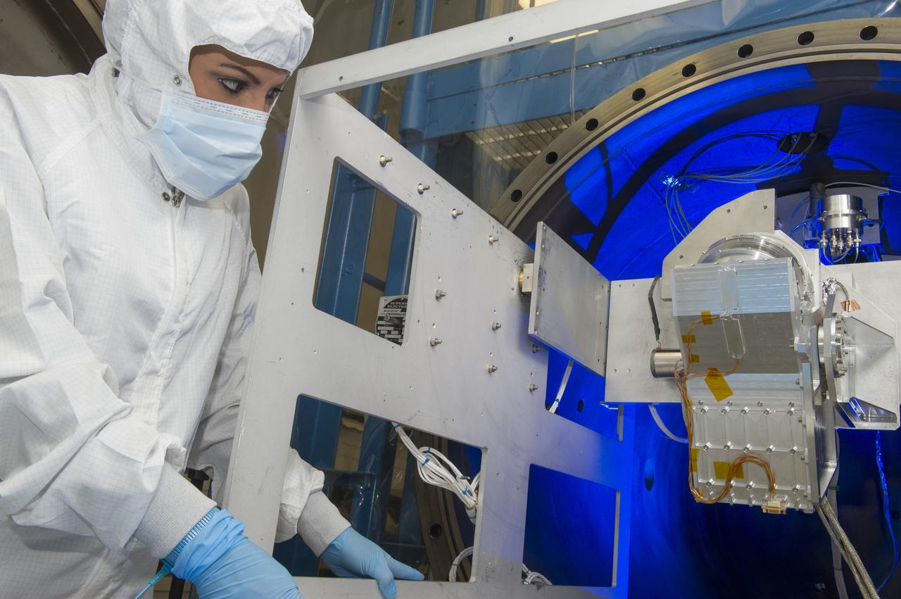
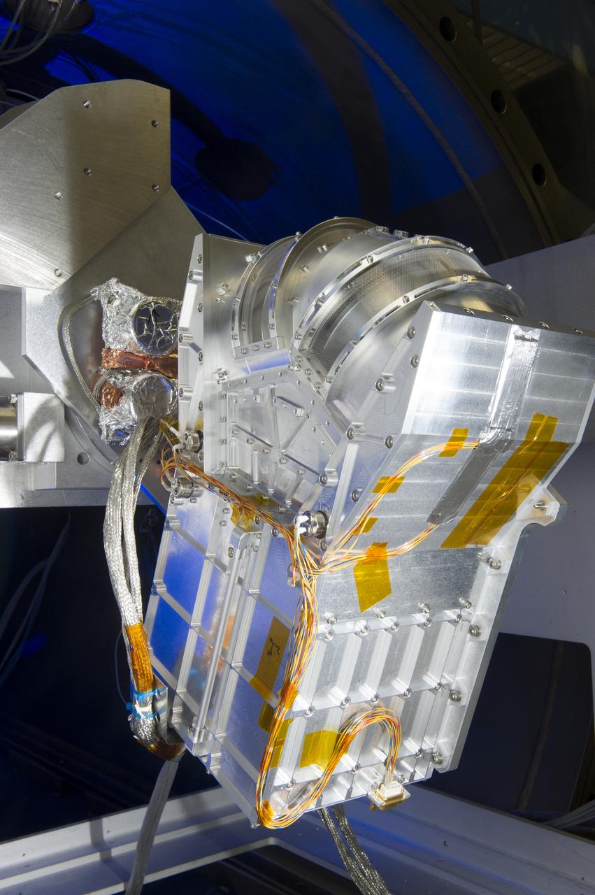
DUAL ION SPECTROMETER (DIS) ENGINEERING TEST UNIT (ETU) AT THE LOW ENERGY ELECTRON AND ION FACILITY (LEEIF), NSSTC
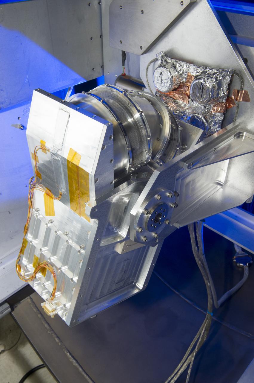
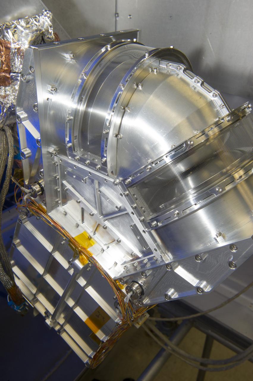
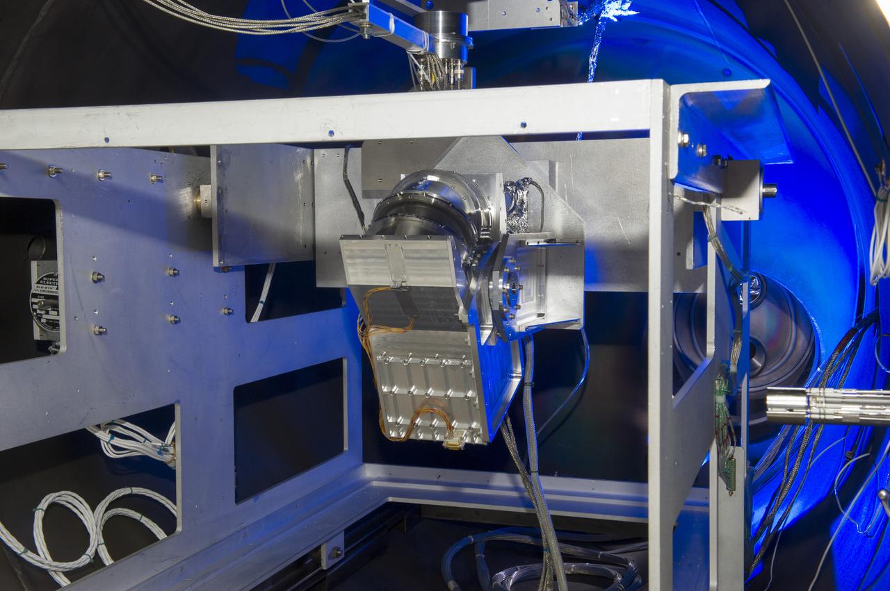
DUAL ION SPECTROMETER (DIS) ENGINEERING TEST UNIT (ETU) AT THE LOW ENERGY ELECTRON AND ION FACILITY (LEEIF), NSSTC
DUAL ION SPECTROMETER (DIS) ENGINEERING TEST UNIT (ETU) AT THE LOW ENERGY ELECTRON AND ION FACILITY (LEEIF), NSSTC
DUAL ION SPECTROMETER (DIS) ENGINEERING TEST UNIT (ETU) AT THE LOW ENERGY ELECTRON AND ION FACILITY (LEEIF), NSSTC
DUAL ION SPECTROMETER (DIS) ENGINEERING TEST UNIT (ETU) AT THE LOW ENERGY ELECTRON AND ION FACILITY (LEEIF), NSSTC
DUAL ION SPECTROMETER (DIS) ENGINEERING TEST UNIT (ETU) AT THE LOW ENERGY ELECTRON AND ION FACILITY (LEEIF), NSSTC
DUAL ION SPECTROMETER (DIS) ENGINEERING TEST UNIT (ETU) AT THE LOW ENERGY ELECTRON AND ION FACILITY (LEEIF), NSSTC
DUAL ION SPECTROMETER (DIS) ENGINEERING TEST UNIT (ETU) AT THE LOW ENERGY ELECTRON AND ION FACILITY (LEEIF), NSSTC

DUAL ION SPECTROMETER (DIS) ENGINEERING TEST UNIT (ETU) AT THE LOW ENERGY ELECTRON AND ION FACILITY (LEEIF), NSSTC
DUAL ION SPECTROMETER (DIS) ENGINEERING TEST UNIT (ETU) AT THE LOW ENERGY ELECTRON AND ION FACILITY (LEEIF), NSSTC
DUAL ION SPECTROMETER (DIS) ENGINEERING TEST UNIT (ETU) AT THE LOW ENERGY ELECTRON AND ION FACILITY (LEEIF), NSSTC
DUAL ION SPECTROMETER (DIS) ENGINEERING TEST UNIT (ETU) AT THE LOW ENERGY ELECTRON AND ION FACILITY (LEEIF), NSSTC
DUAL ION SPECTROMETER (DIS) ENGINEERING TEST UNIT (ETU) AT THE LOW ENERGY ELECTRON AND ION FACILITY (LEEIF), NSSTC
DUAL ION SPECTROMETER (DIS) ENGINEERING TEST UNIT (ETU) AT THE LOW ENERGY ELECTRON AND ION FACILITY (LEEIF), NSSTC
DUAL ION SPECTROMETER (DIS) ENGINEERING TEST UNIT (ETU) AT THE LOW ENERGY ELECTRON AND ION FACILITY (LEEIF), NSSTC
DUAL ION SPECTROMETER (DIS) ENGINEERING TEST UNIT (ETU) AT THE LOW ENERGY ELECTRON AND ION FACILITY (LEEIF), NSSTC

NASA's highly modified F-15A (Serial #71-0287) used for digital electronic flight and engine control systems research, at sunrise on the ramp at the Dryden Flight Research Facility, Edwards, California. The F-15 was called the HIDEC (Highly Integrated Digital Electronic Control) flight facility. Research programs flown on the testbed vehicle have demonstrated improved rates of climb, fuel savings, and engine thrust by optimizing systems performance. The aircraft also tested and evaluated a computerized self-repairing flight control system for the Air Force that detects damaged or failed flight control surfaces. The system then reconfigures undamaged control surfaces so the mission can continue or the aircraft is landed safely.
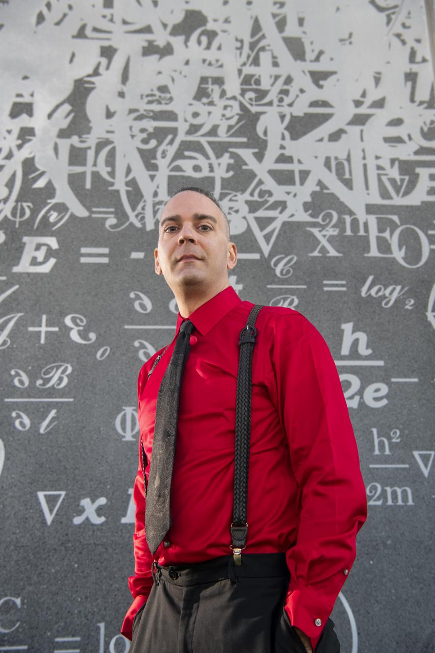
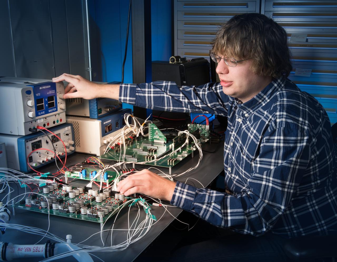
Dan Raible, an Electronics Engineer in NASA Glenn Research Center’s Optics and Photonics Branch. Raible has a long history with NASA. Someone in his family has worked at what is now NASA Glenn Research since it was NACA. His grandfather, Four uncles and his father all supported space and aeronautics research.
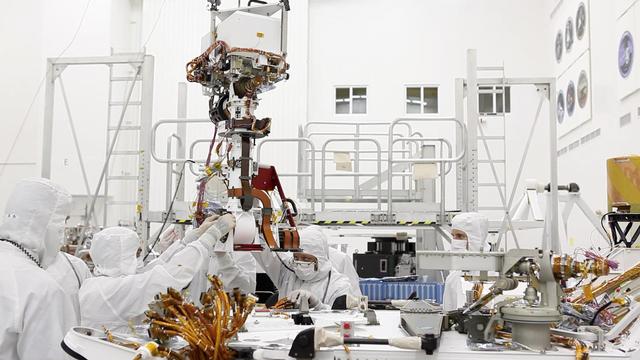
In the clean room at NASA Jet Propulsion Laboratory, engineers gather around the base of Curiosity neck the Mast as they slowly lower it into place for attachment to the rover body the Wet Electronics Box, or WEB.
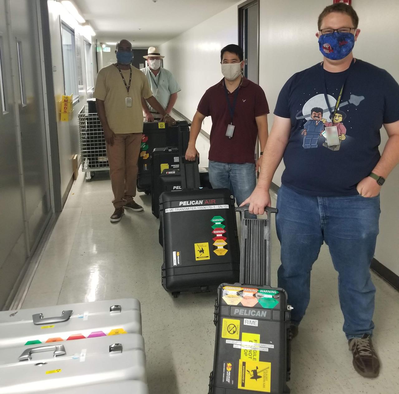
NASA's Jet Propulsion Laboratory built and shipped the receiver, transmitter and electronics necessary to complete the radar instrument for the Jupiter Icy Moons Explorer (JUICE) mission. Set to launch in 2022, JUICE is the ESA (European Space Agency) mission to explore Jupiter and its three large icy moons. From front: JPL engineers and technicians Jeremy Steinert, Jordan Tanabe, Glenn Jeffery, and Robert Johnson follow COVID-19 Safe-at-Work guidelines as they transport the transmitter and electronics on Aug. 19, 2020, for shipping to the Italian Space Agency (ASI). ASI is collaborating with JPL to build the instrument, called Radar for Icy Moon Exploration (RIME). It is one of 10 instruments that will fly aboard JUICE. https://photojournal.jpl.nasa.gov/catalog/PIA24026
NASA Engineering and Safety Center's, NESC, Mission Tech Update Photos 2013, Electron Optics Laboratory
Environmental Portrait of a Telecommunications Engineer with the University of Indiana Heart Pump, Motor Controller Electronics
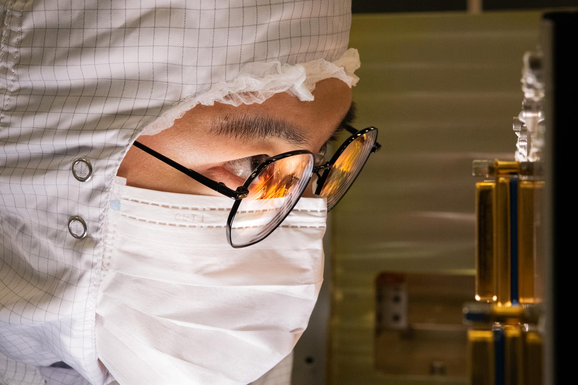
OSAM-1 electronics engineer, Sam Zhao, peers inside the robotic electronics unit inside the cleanroom at Goddard Space Flight Center, Greenbelt, Md., Oct 8, 2024. This photo has been approved for public release by OSAM-1 project management and Nasa Export Control. NASA/Mike Guinto
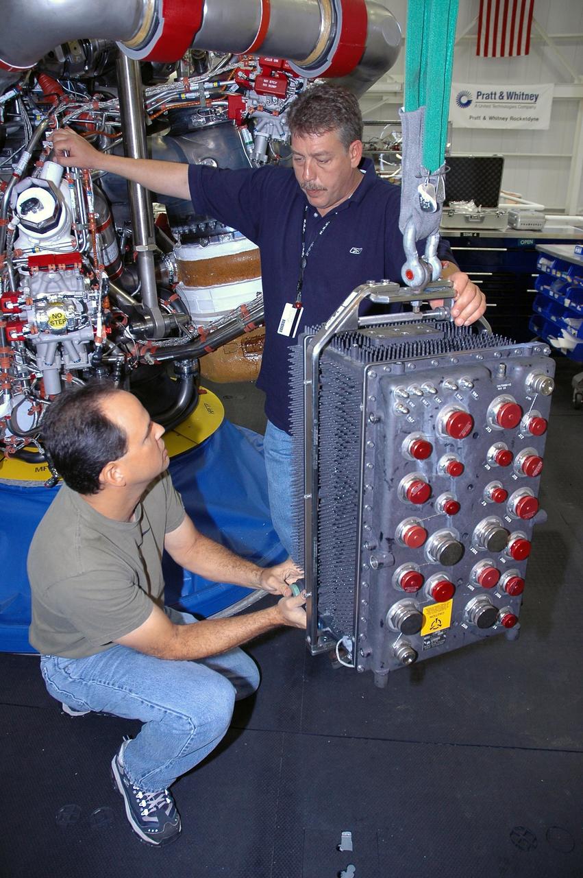
KENNEDY SPACE CENTER, FLA. -- In Space Shuttle Maine Engine Shop, workers get ready to install an engine controller in one of the three main engines (behind them) of the orbiter Discovery. The controller is an electronics package mounted on each space shuttle main engine. It contains two digital computers and the associated electronics to control all main engine components and operations. The controller is attached to the main combustion chamber by shock-mounted fittings. Discovery is the designated orbiter for mission STS-120 to the International Space Station. It will carry a payload that includes the Node 2 module, named Harmony. Launch is targeted for no earlier than Oct. 20. Photo credit: NASA/Cory Huston
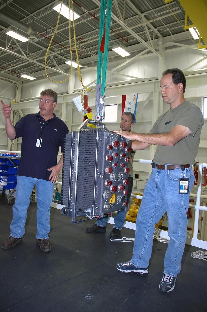
KENNEDY SPACE CENTER, FLA. -- In the Space Shuttle Maine Engine Shop, workers get ready to install an engine controller in one of the three main engines of the orbiter Discovery. The controller is an electronics package mounted on each space shuttle main engine. It contains two digital computers and the associated electronics to control all main engine components and operations. The controller is attached to the main combustion chamber by shock-mounted fittings. Discovery is the designated orbiter for mission STS-120 to the International Space Station. It will carry a payload that includes the Node 2 module, named Harmony. Launch is targeted for no earlier than Oct. 20. Photo credit: NASA/Cory Huston
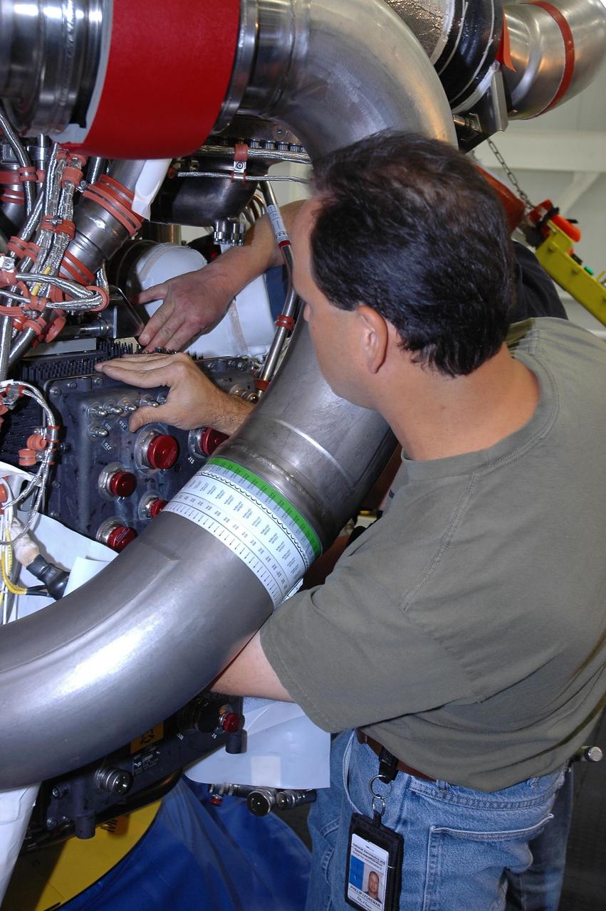
KENNEDY SPACE CENTER, FLA. -- In the Space Shuttle Maine Engine Shop, workers are installing an engine controller in one of the three main engines of the orbiter Discovery. The controller is an electronics package mounted on each space shuttle main engine. It contains two digital computers and the associated electronics to control all main engine components and operations. The controller is attached to the main combustion chamber by shock-mounted fittings. Discovery is the designated orbiter for mission STS-120 to the International Space Station. It will carry a payload that includes the Node 2 module, named Harmony. Launch is targeted for no earlier than Oct. 20. Photo credit: NASA/Cory Huston
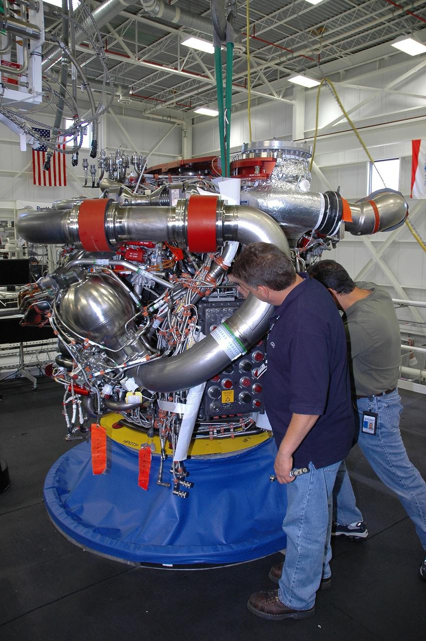
KENNEDY SPACE CENTER, FLA. -- In the Space Shuttle Maine Engine Shop, workers check the installation of an engine controller in one of the three main engines of the orbiter Discovery. The controller is an electronics package mounted on each space shuttle main engine. It contains two digital computers and the associated electronics to control all main engine components and operations. The controller is attached to the main combustion chamber by shock-mounted fittings. Discovery is the designated orbiter for mission STS-120 to the International Space Station. It will carry a payload that includes the Node 2 module, named Harmony. Launch is targeted for no earlier than Oct. 20. Photo credit: NASA/Cory Huston
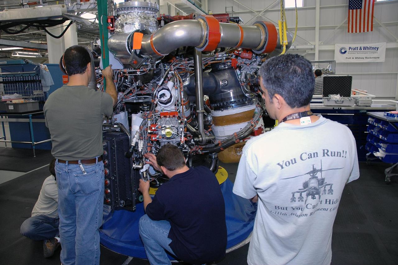
KENNEDY SPACE CENTER, FLA. -- In the Space Shuttle Maine Engine Shop, workers are installing an engine controller in one of the three main engines of the orbiter Discovery. The controller is an electronics package mounted on each space shuttle main engine. It contains two digital computers and the associated electronics to control all main engine components and operations. The controller is attached to the main combustion chamber by shock-mounted fittings. Discovery is the designated orbiter for mission STS-120 to the International Space Station. It will carry a payload that includes the Node 2 module, named Harmony. Launch is targeted for no earlier than Oct. 20. Photo credit: NASA/Cory Huston
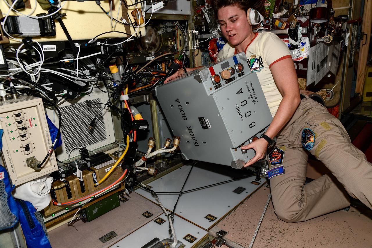
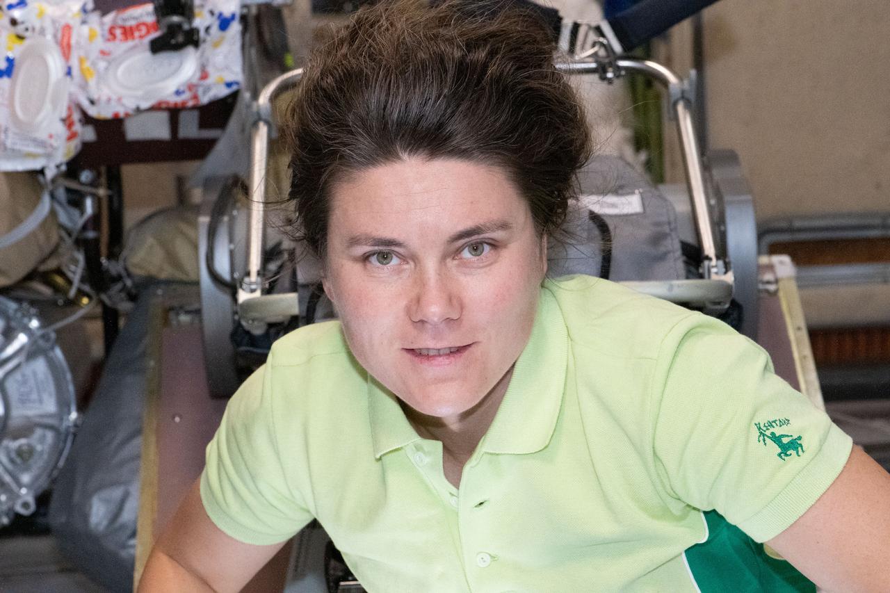
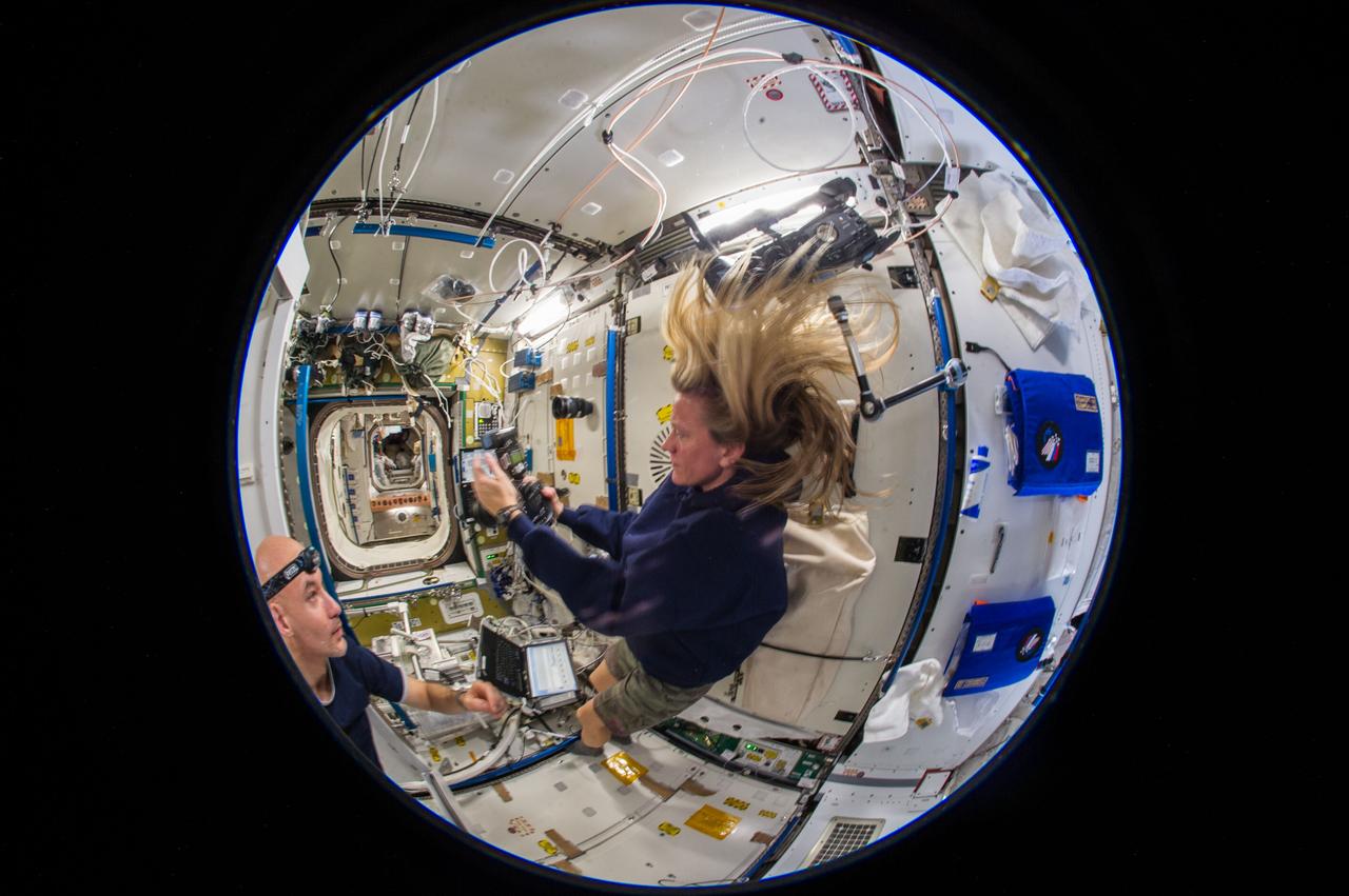
iss068e041665 (Jan. 23, 2023) --- Roscosmos cosmonaut and Expedition 68 Flight Engineer Anna Kikina works on electronics hardware maintenance inside the International Space Station.
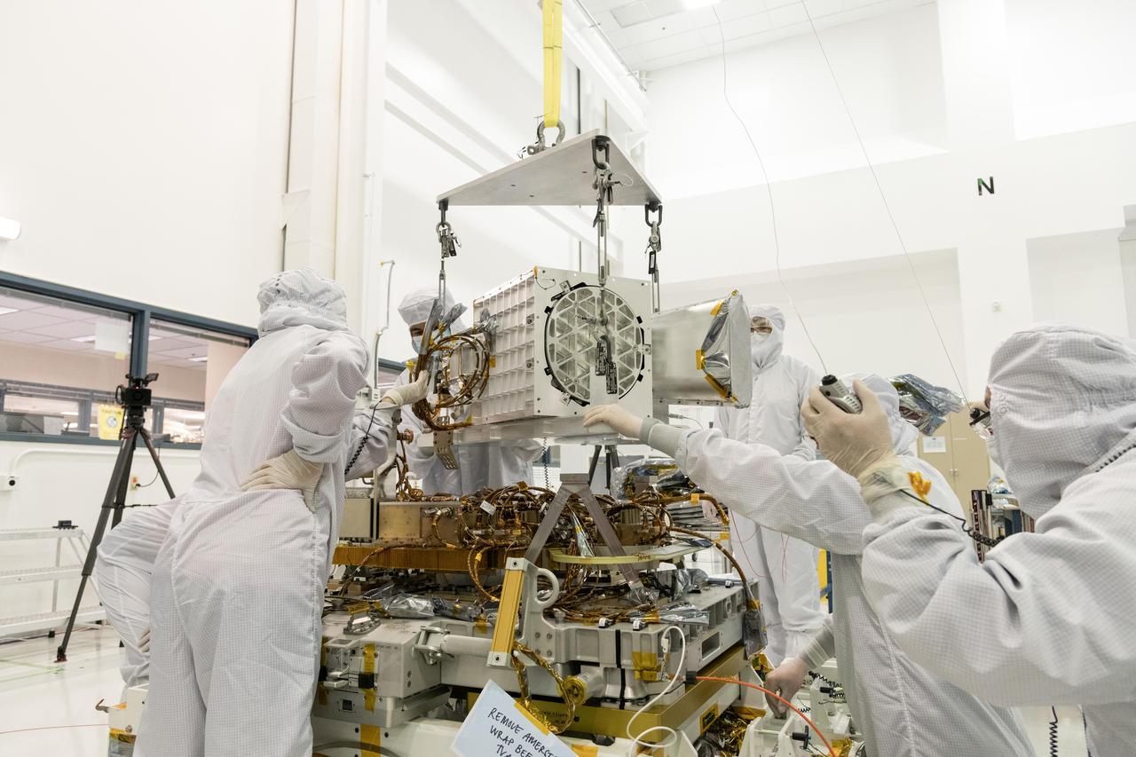
Engineers and technicians at NASA's Jet Propulsion Laboratory in Southern California assemble components of the Earth Surface Mineral Dust Source Investigation (EMIT) mission instrument in December 2021. The upper portion consists of EMIT's optical subsystem, including a telescope and imaging spectrometer, while the baseplate below holds electronics. EMIT will collect measurements of 10 important surface minerals – hematite, goethite, illite, vermiculite, calcite, dolomite, montmorillonite, kaolinite, chlorite, and gypsum – in arid regions between 50-degree south and north latitudes in Africa, Asia, North and South America, and Australia. The data EMIT collects will help scientists better understand the role of airborne dust particles in heating and cooling Earth's atmosphere on global and regional scales. https://photojournal.jpl.nasa.gov/catalog/PIA25146
iss066e188276 (April 4, 20222) --- NASA astronaut and Expedition 66 Flight Engineer Raja Chari is pictured during a six-hour and 54-minute spacewalk to install thermal gear and electronic components on the International Space Station.
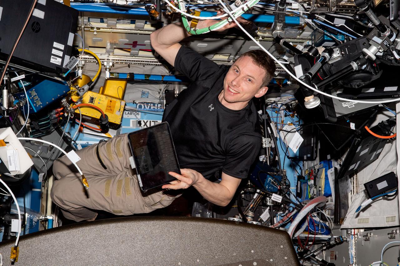
iss069e033730 (July 18, 2023) --- NASA astronaut and Expedition 69 Flight Engineer Woody Hoburg is pictured inside the Destiny laboratory module installing electronics and communications hardware.
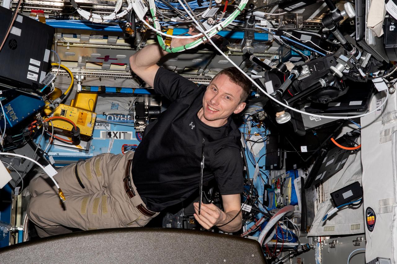
iss069e033729 (July 18, 2023) -- NASA astronaut and Expedition 69 Flight Engineer Woody Hoburg poses for a photo inside the Destiny module as he installs electronics and communications hardware.
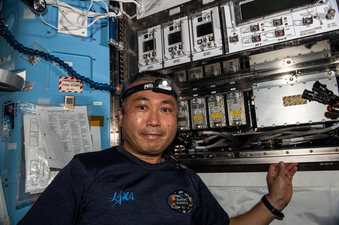
iss068e017570 (Oct. 19, 2022) --- Expedition 68 Flight Engineer Koichi Wakata of the Japan Aerospace Exploration Agency (JAXA) works in the U.S. Quest airlock swapping electronics components and checking cable connections inside an avionics rack.
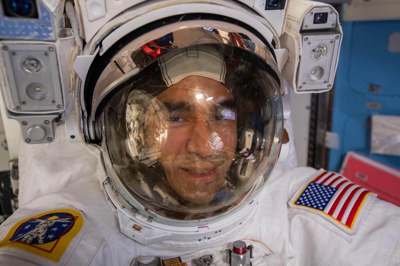
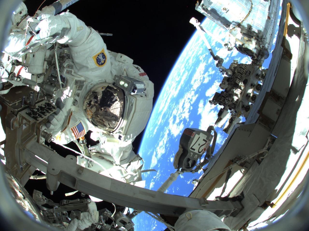
iss066e174346 (March 23, 2022) --- NASA astronaut and Expediution 66 Flight Engineer Raja Chari is pictured in his U.S. spacesuit prior to beginning a spacewalk to install thermal gear and electronics components on the International Space Station.
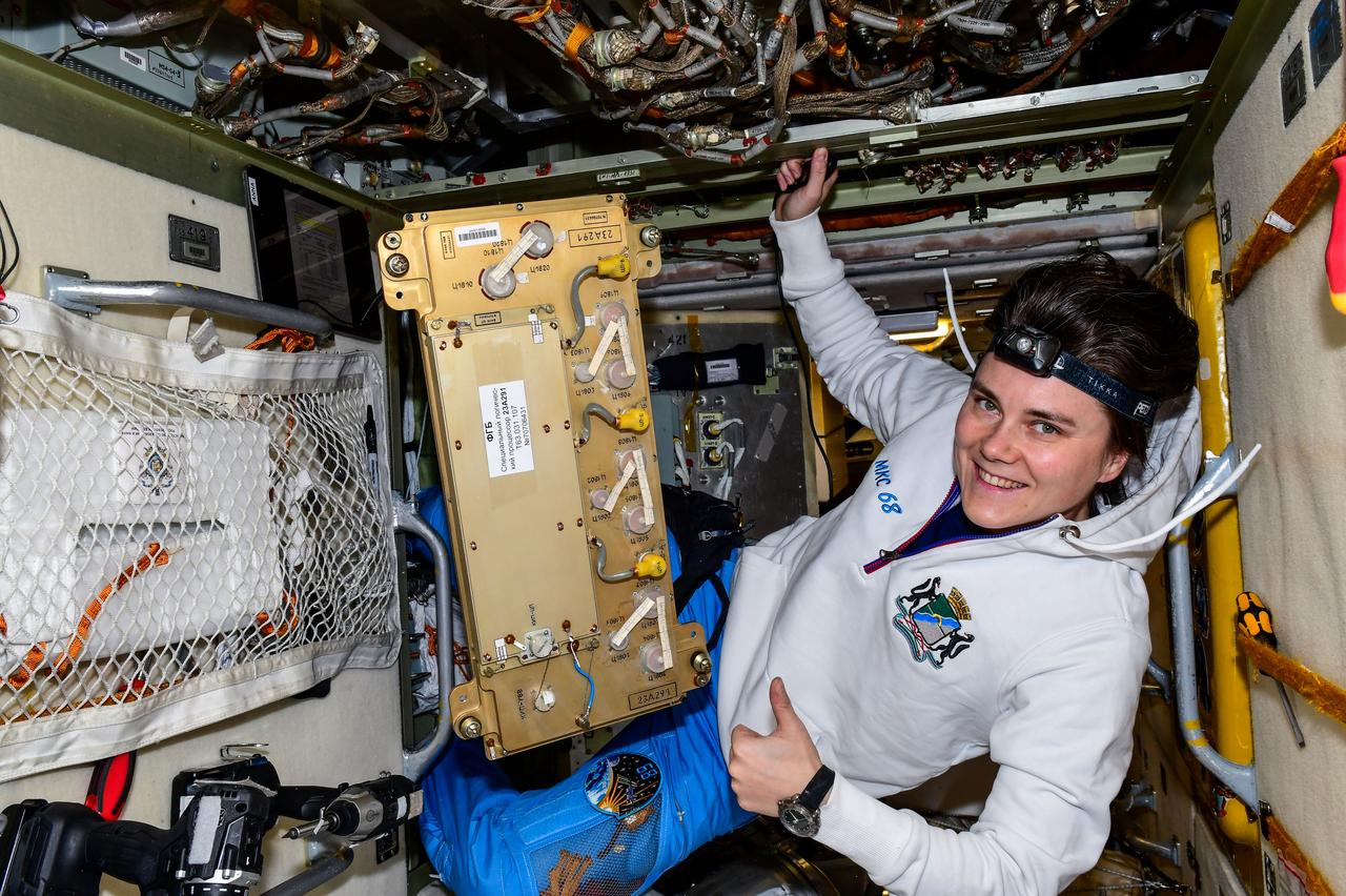
iss068e040769 (Jan. 17, 2023) --- Roscosmos cosmonaut and Expedition 68 Flight Engineer Anna Kikina removes and replaces electronics hardware inside the International Space Station's Zarya module. Credit: Roscosmos
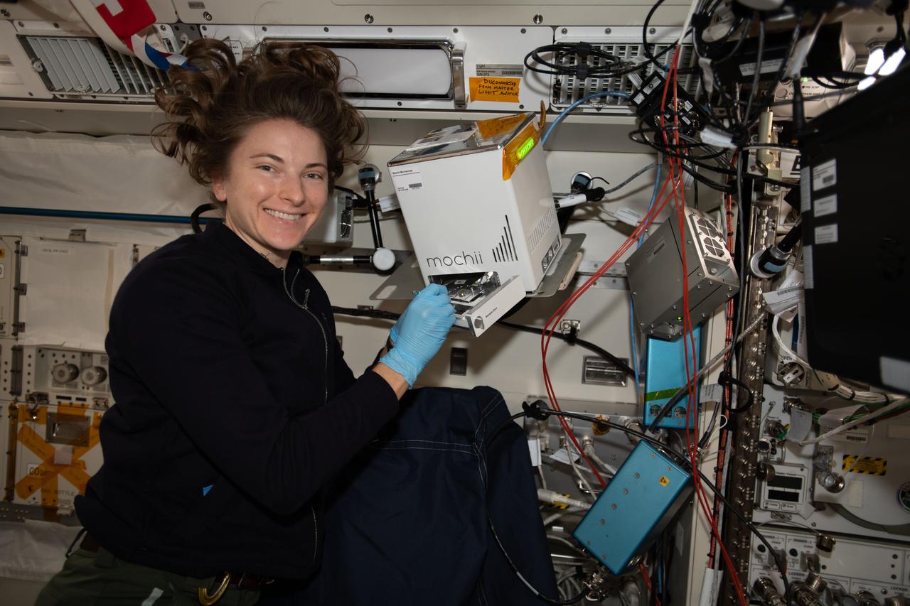
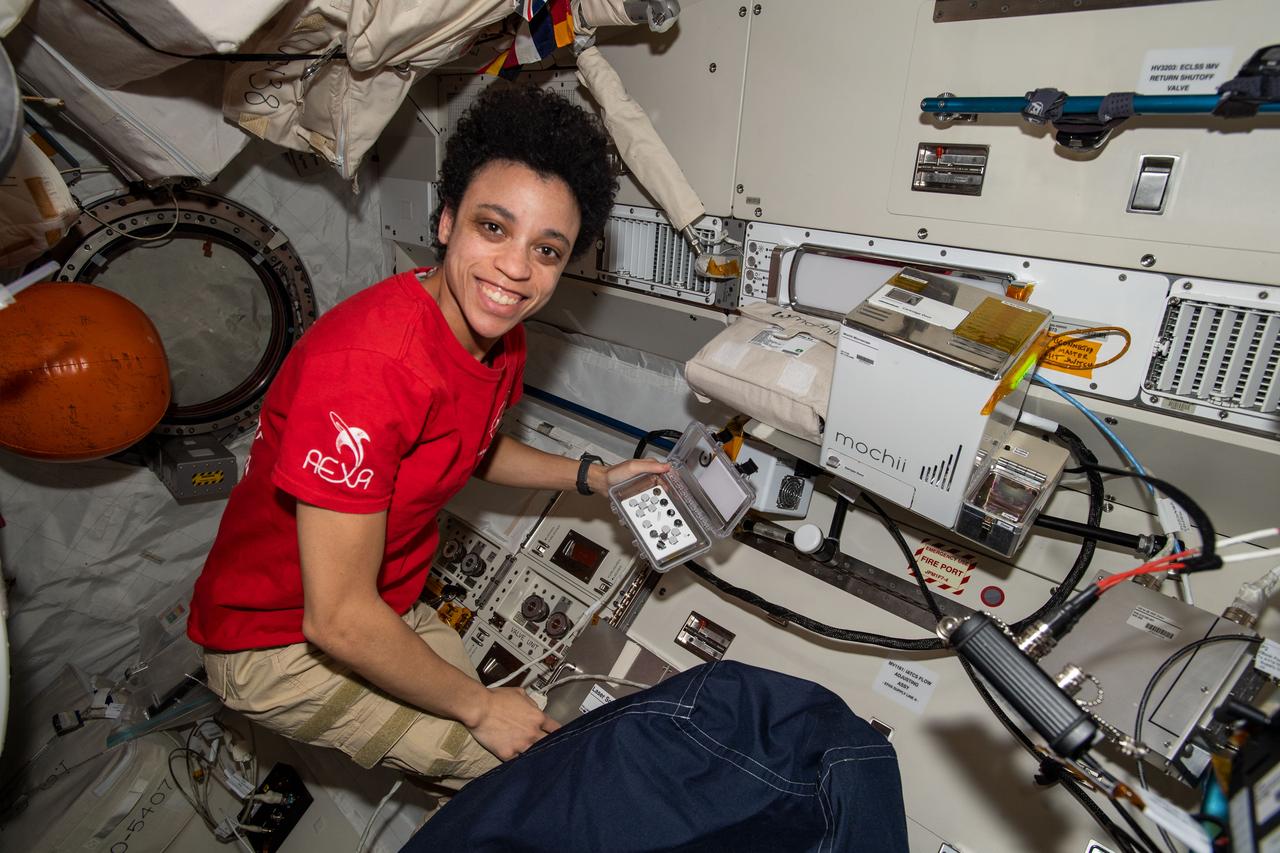
iss066e110569 (Jan. 10, 2022) --- NASA astronaut and Expedition 66 Flight Engineer Kayla Barron sets up and installs the Mochii electron-scanning microscope that can be used to identify trace particles aboard the International Space Station.
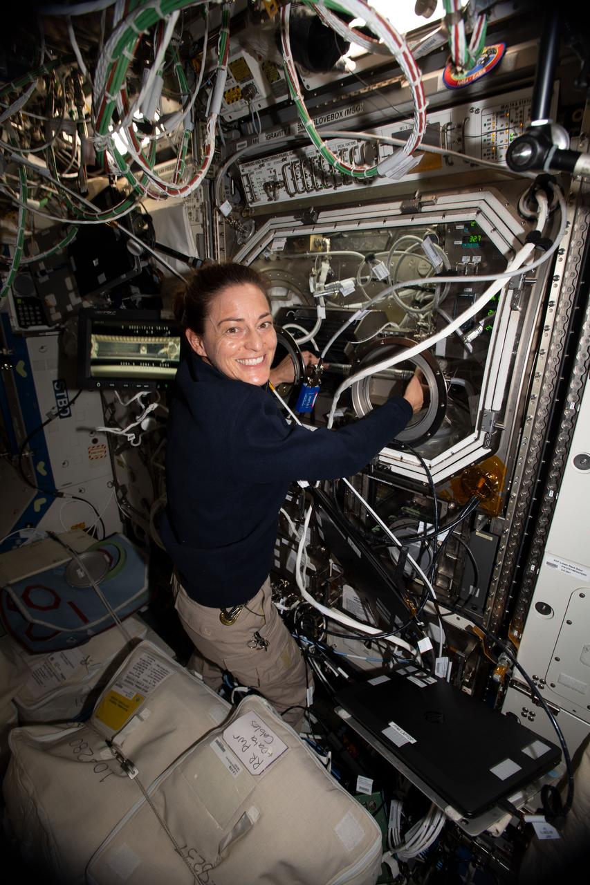
iss068e029618 (Dec. 14, 2022) --- NASA astronaut and Expedition 68 Flight Engineer Nicole Mann swaps samples inside the Microgravity Science Glovebox for a space physics study demonstrating a passive cooling system for electronic devices in microgravity.
iss068e027615 (Dec. 6, 2022) --- Roscosmos cosmonaut and Expedition 68 Flight Engineer Anna Kikina is pictured conducting electronics maintenance aboard the International Space Station. Credit: Roscosmos
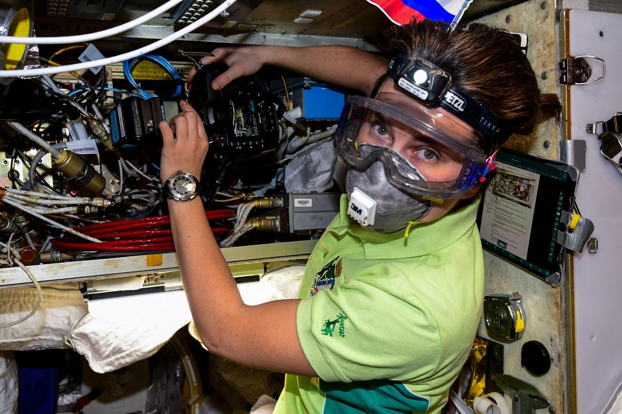
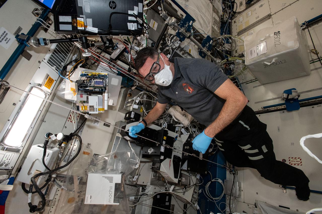
iss068e032401 (Dec. 22, 2023) --- Roscosmos cosmonaut and Expedition 68 Flight Engineer conducts communications and electronics maintenance while wearing personal protective equipment aboard the International Space Station.
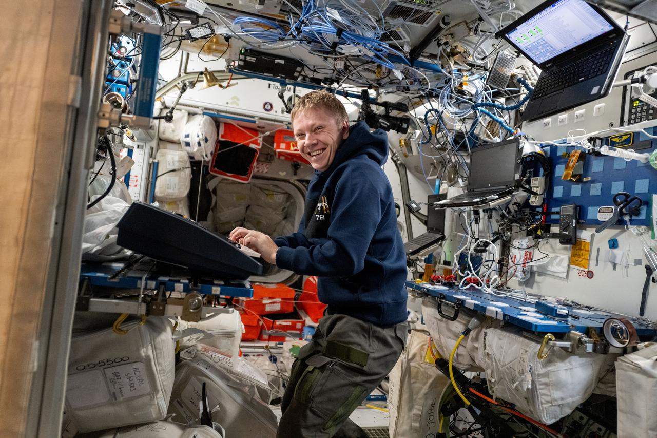
iss072e143768 (Nov. 1, 2024) --- Roscosmos cosmonaut and Expedition 72 Flight Engineer Aleksandr Gorbunov plays an electronic keyboard aboard the International Space Station's Harmony module.

iss068e027424 (Dec. 5, 2022) --- Roscosmos cosmonaut and Expedition 68 Flight Engineer Anna Kikina services electronics hardware aboard the International Space Station. Credit: Roscosmos
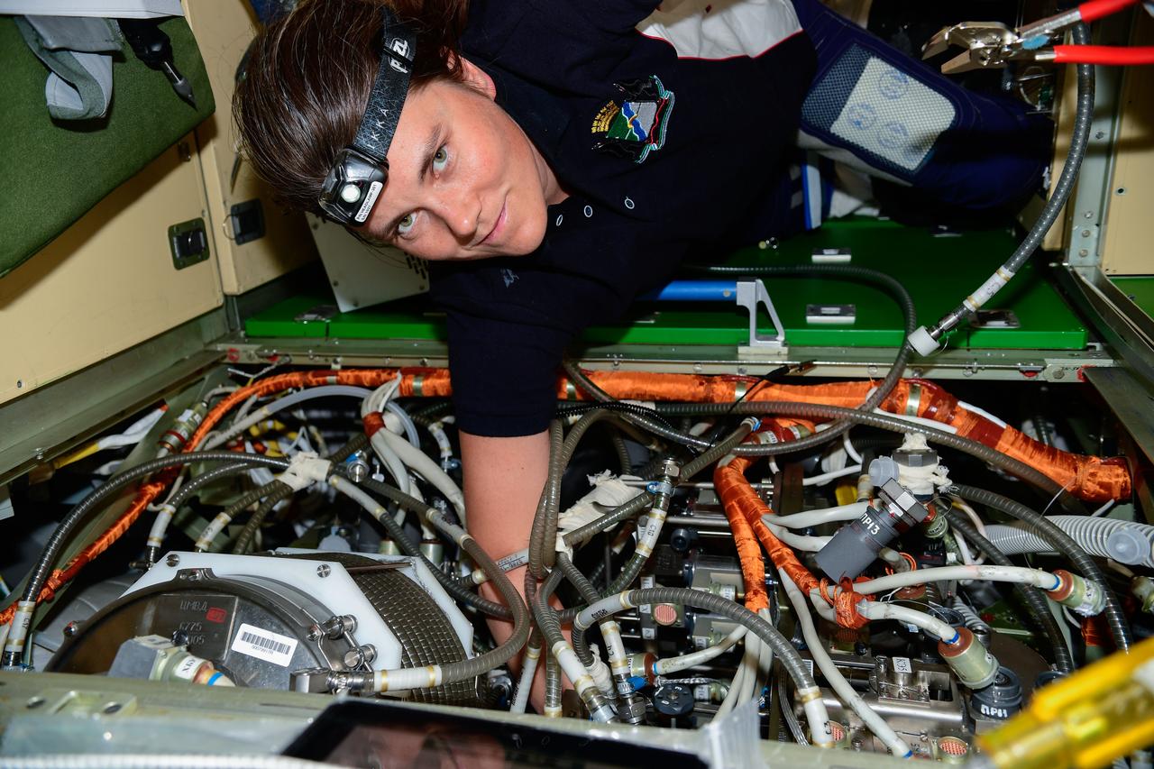
iss068e017239 (Oct. 13, 2022) --- Roscosmos cosmonaut and Expedition 68 Flight Engineer Anna Kikina works on electronics and communications maintenance inside the International Space Station's Nauka multipurpose laboratory module. Credit: Roscosmos
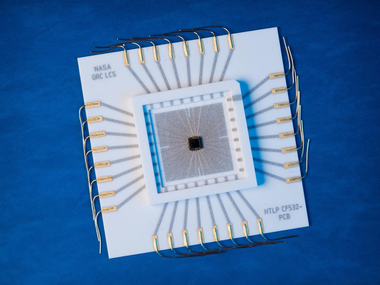
A multilevel interconnect silicon carbide integrated circuit chip with co-fired ceramic package and circuit board recently developed at the NASA GRC Smart Sensors and Electronics Systems Branch for high temperature applications. High temperature silicon carbide electronics and compatible packaging technologies are elements of instrumentation for aerospace engine control and long term inner-solar planet explorations.
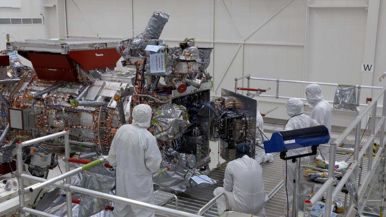
Engineers and technicians are seen closing the vault of NASA's Europa Clipper in the main clean room of the Spacecraft Assembly Facility at the agency's Jet Propulsion Laboratory in Southern California on Oct. 7, 2023. The vault will protect the sophisticated electronics of the spacecraft as it orbits Jupiter and endures one of the most punishing radiation environments in our solar system. The mission is targeting October 2024 for the launch of its spacecraft, which will fly by Europa about 50 times. Europa Clipper's main science goal is to determine whether there are places below Jupiter's icy moon, Europa, that could support life. The mission's three main science objectives are to determine the thickness of the moon's icy shell and its surface interactions with the ocean below, to investigate its composition, and to characterize its geology. The mission's detailed exploration of Europa will help scientists better understand the astrobiological potential for habitable worlds beyond our planet. https://photojournal.jpl.nasa.gov/catalog/PIA25959
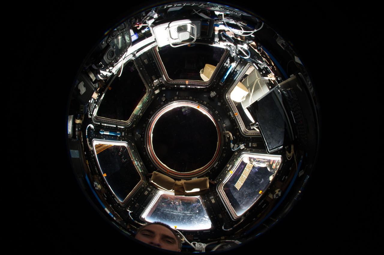
ISS036-E-022157 (20 July 2013) --- A fisheye lens attached to an electronic still camera was used to capture this image of the International Space Station’s Cupola and NASA astronaut Chris Cassidy (mostly out of frame at bottom), Expedition 36 flight engineer.
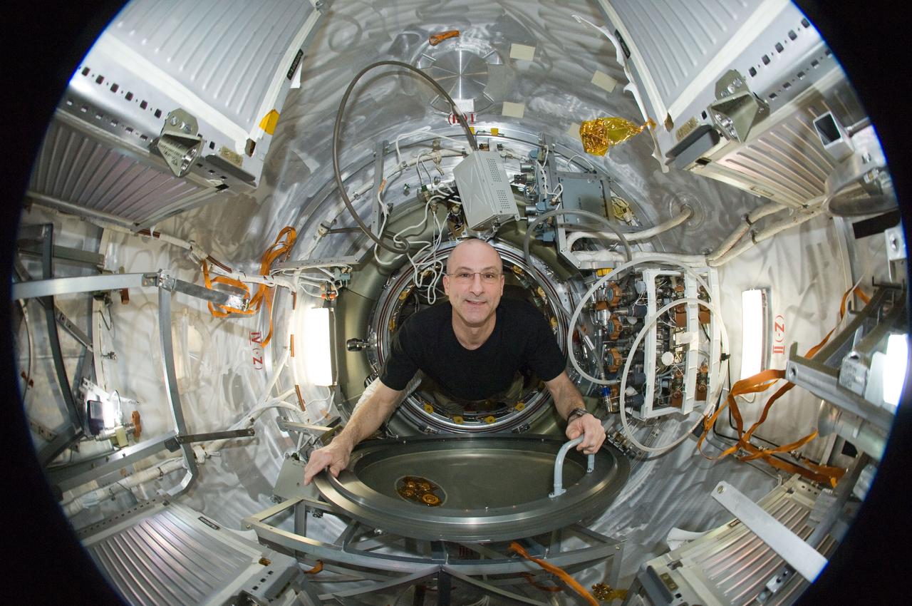
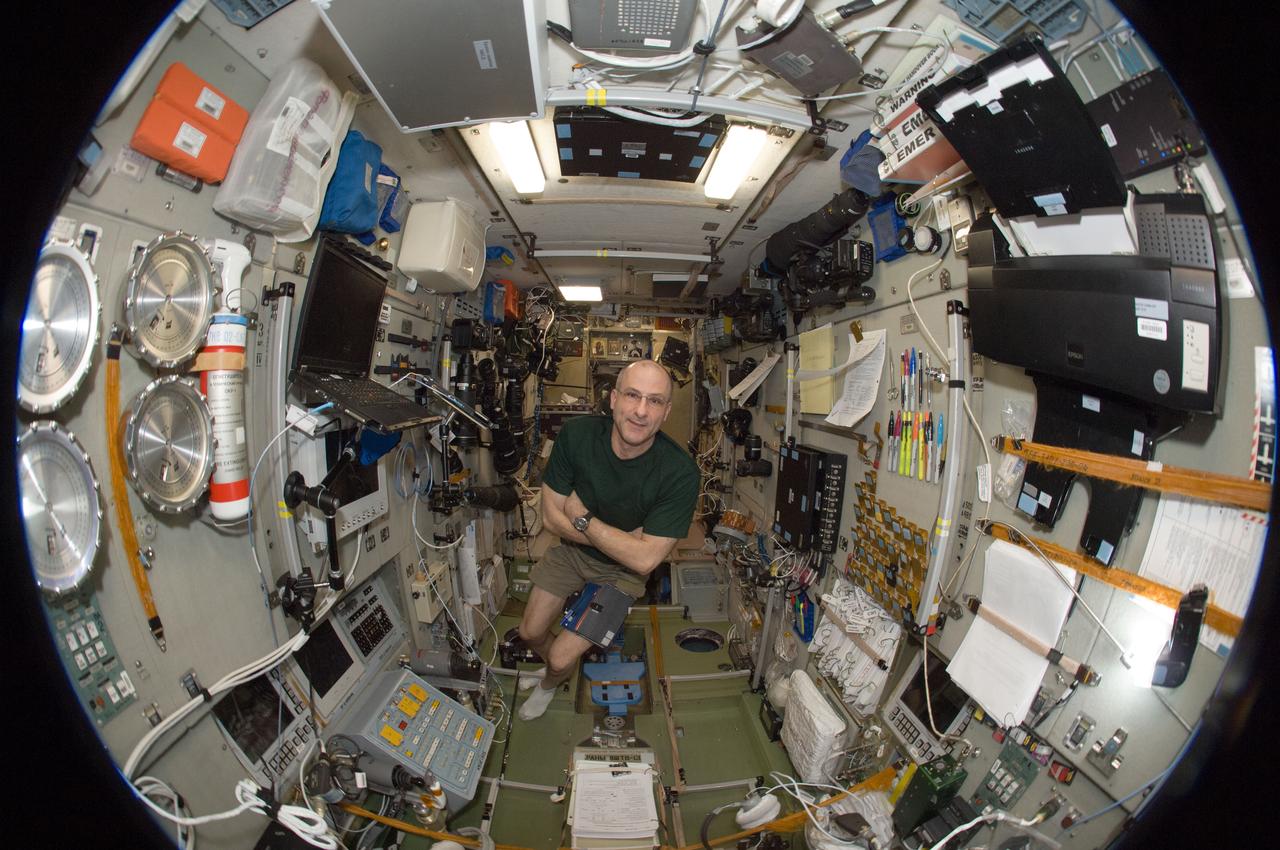
ISS031-E-035441 (15 May 2012) --- A fisheye lens attached to an electronic still camera was used to capture this image of NASA astronaut Don Pettit, Expedition 31 flight engineer, in the Progress 47 resupply vehicle docked to the International Space Station’s Pirs Docking Compartment.
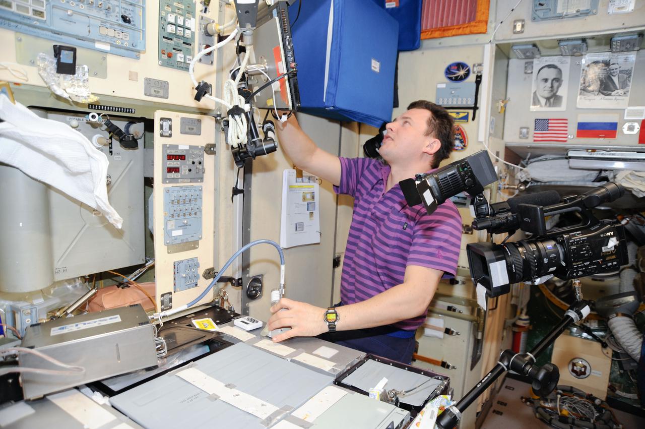
ISS034-E-051551 (21 Feb. 2013) --- Cosmonaut Roman Romanenko, Expedition 34 flight engineer, works with the Electronic Nose hardware in the Zvezda service module aboard the International Space Station in Earth orbit. This hardware is used to measure contamination in the environment should there be hard to detect chemical leaks or spills.
iss065e241981 (Aug. 12, 2021) --- NASA astronaut and Expedition 65 Flight Engineer Shane Kimbrough conducts maintenance on a miniature electron microscope, called Mochii, to support spectroscopic investigations and analyses of microscopic particles aboard the International Space Station.

iss066e174831 (March 23, 2022) --- NASA astronaut and Expedition 66 Flight Engineer Raja Chari is pictured attached to the Canadarm2 robotic arm during a six-hour and 54-minute spacewalk to install thermal gear and electronic components on the International Space Station.
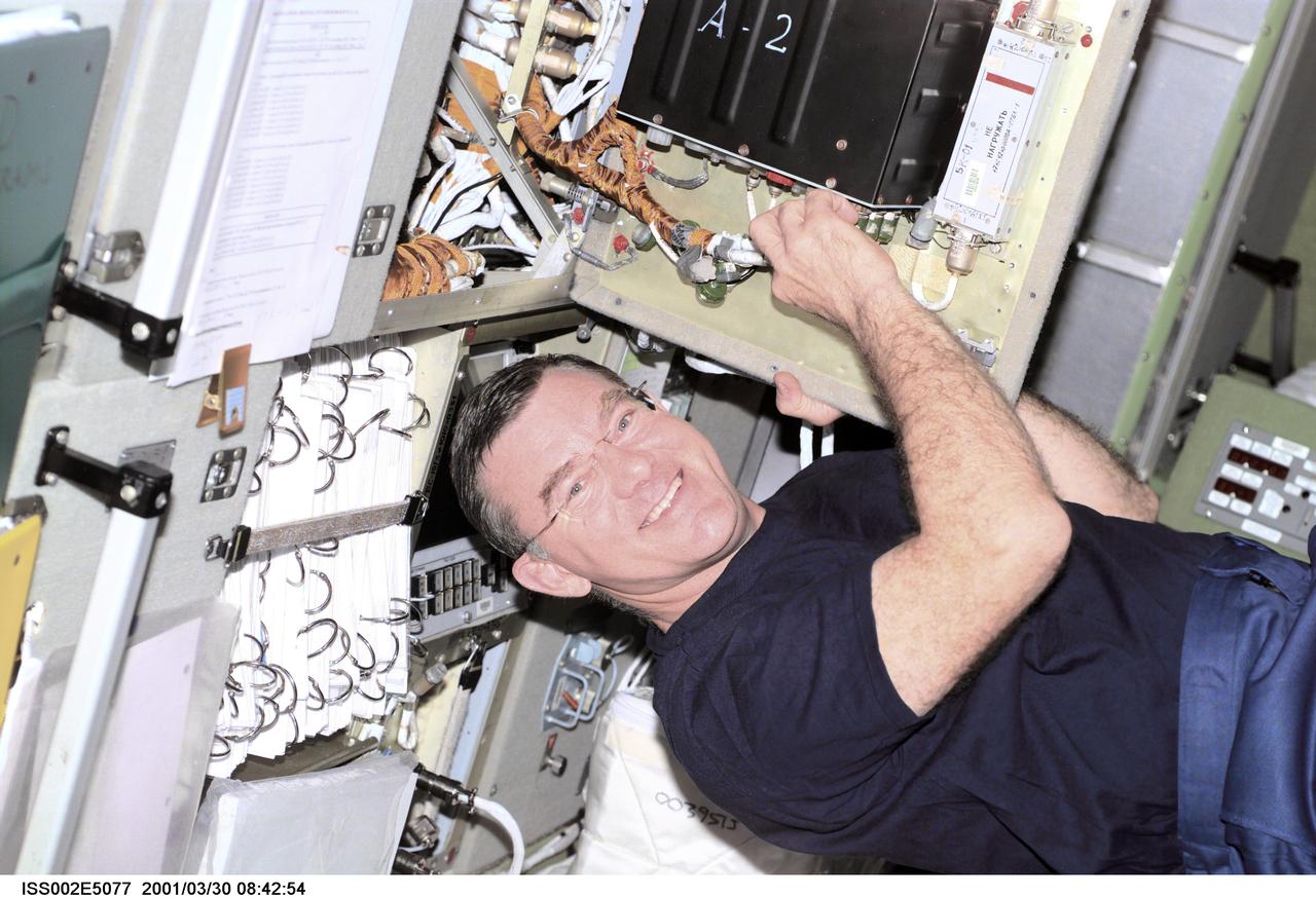
ISS002-E-5077 (30 March 2001) --- Astronaut James S. Voss, Expedition Two flight engineer, performs an electronics maintenance task in the Zvezda Service Module aboard the International Space Station (ISS). The photo was recorded with a digital still camera.
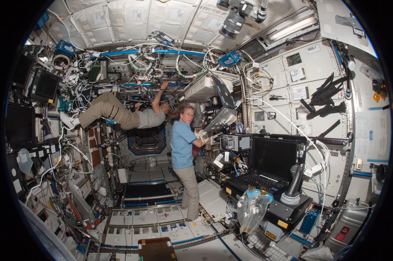
ISS036-E-019781 (24 June 2013) --- A fisheye lens attached to an electronic still camera was used to capture this image of European Space Agency astronaut Luca Parmitano and NASA astronaut Karen Nyberg, both Expedition 36 flight engineers, as they work in the Destiny laboratory of the International Space Station.
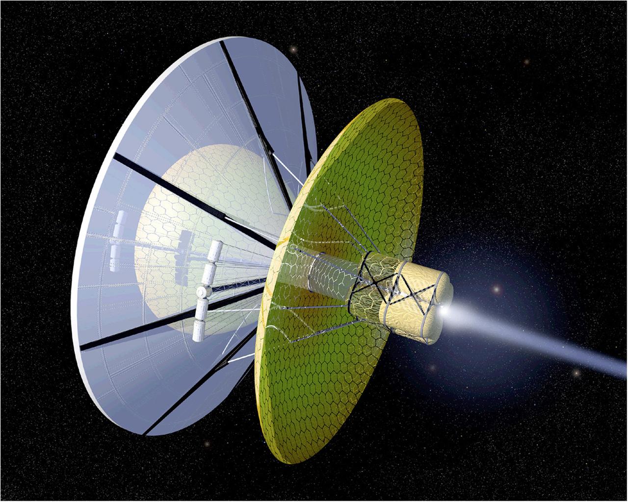
The Boussard Interstellar Ramjet engine concept uses interstellar hydrogen scooped up from its environment as the spacecraft passes by to provide propellant mass. The hydrogen is then ionized and then collected by an electromagentic field. In this image, an onboard laser is uded to heat the plasma, and the laser or electron beam is used to trigger fusion pulses thereby creating propulsion.
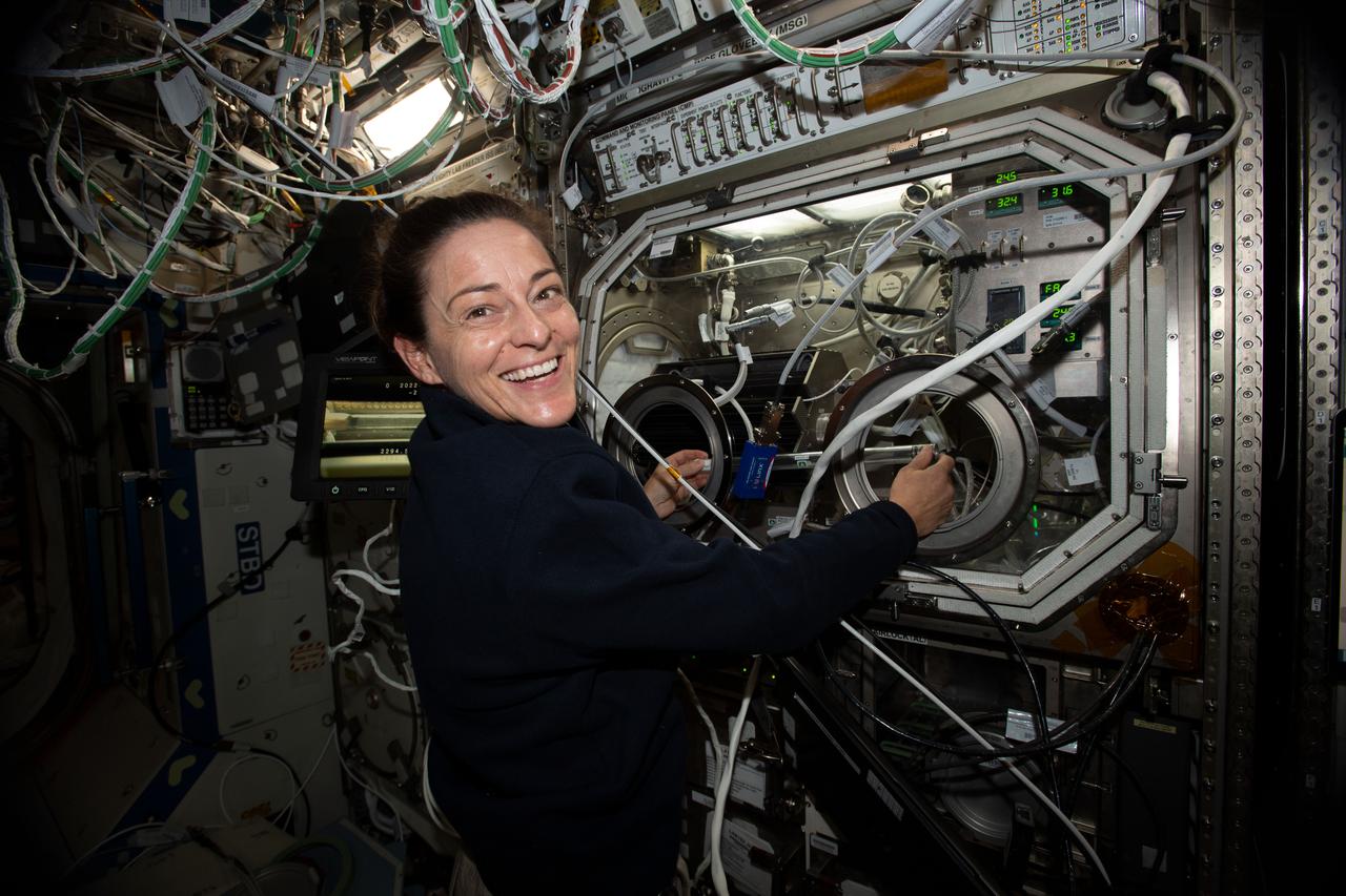
iss068e029599 (Dec. 14, 2022) --- NASA astronaut and Expedition 68 Flight Engineer Nicole Mann exchanges samples inside the Microgravity Science Glovebox for the Pore Formation and Mobility Investigation. The space physics study demonstrates a passive cooling system for electronic devices in microgravity using a micro-structured surface.
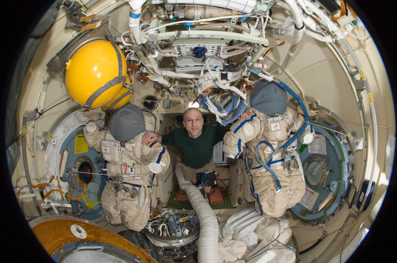
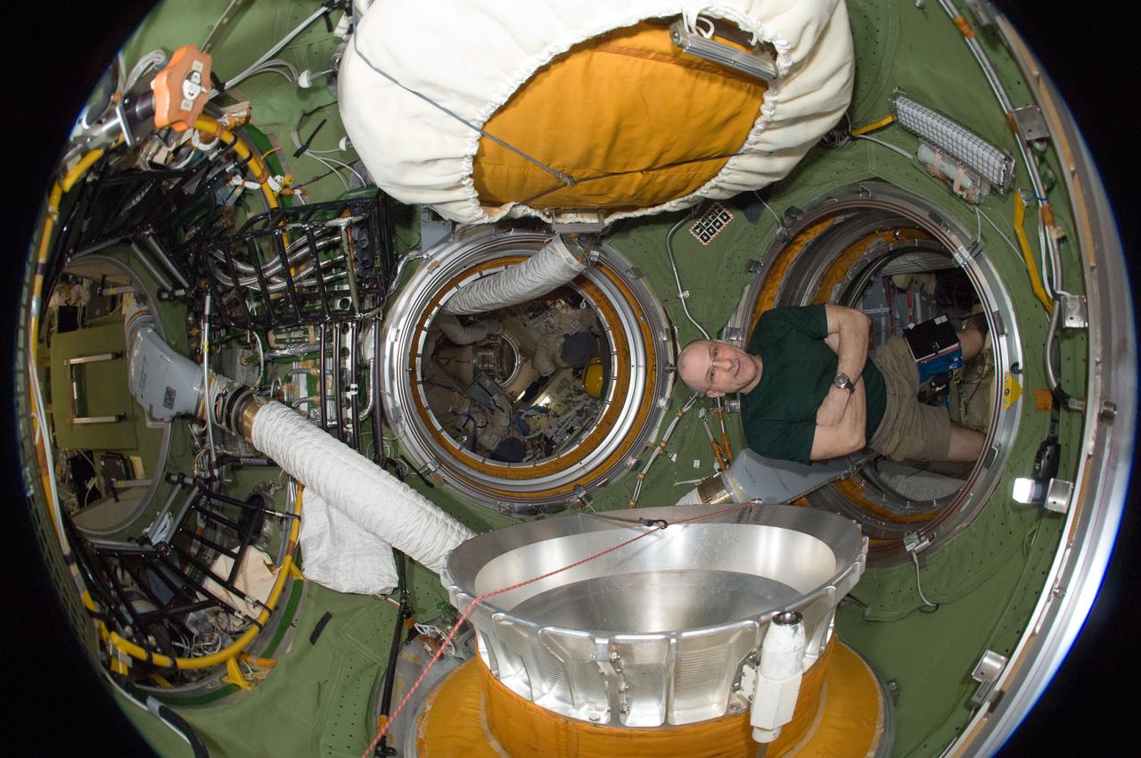
ISS031-E-030471 (12 May 2012) --- A fisheye lens attached to an electronic still camera was used to capture this image of NASA astronaut Don Pettit, Expedition 31 flight engineer, with two Russian Orlan spacesuits in the Pirs Docking Compartment of the International Space Station.
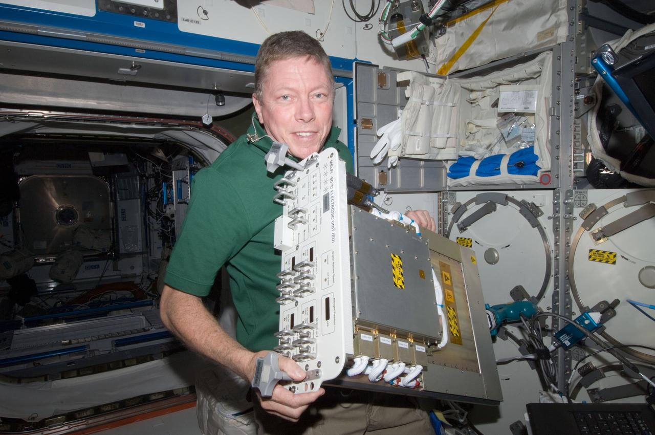
ISS028-E-013797 (1 July 2011) --- NASA astronaut Mike Fossum, Expedition 28 flight engineer, replaces a failed electronic unit for the Minus Eighty Laboratory Freezer for ISS 3 (MELFI-3) with a spare unit in the Kibo laboratory of the International Space Station.
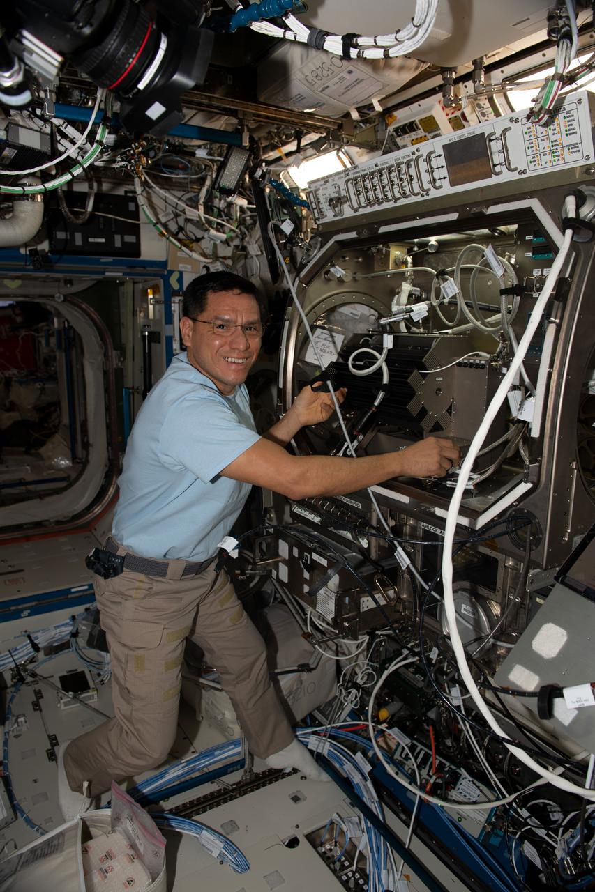
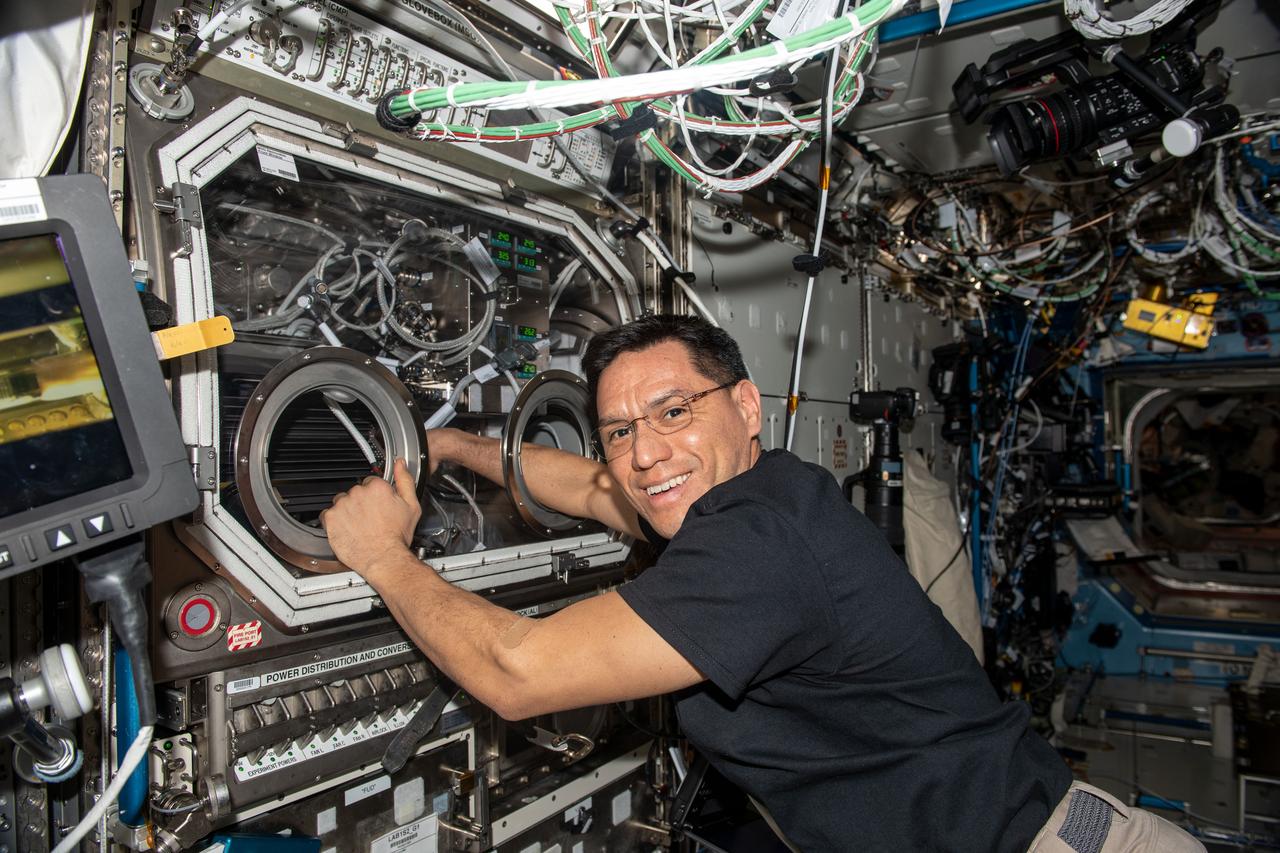
iss068e024574 (Nov. 26, 2022) --- NASA astronaut and Expedition 68 Flight Engineer Frank Rubio works in the Microgravity Science Glovebox setting up hardware for the Pore Formation and Mobility Investigation. The space physics study demonstrates a passive cooling system for electronic devices in microgravity using a micro-structured surface.

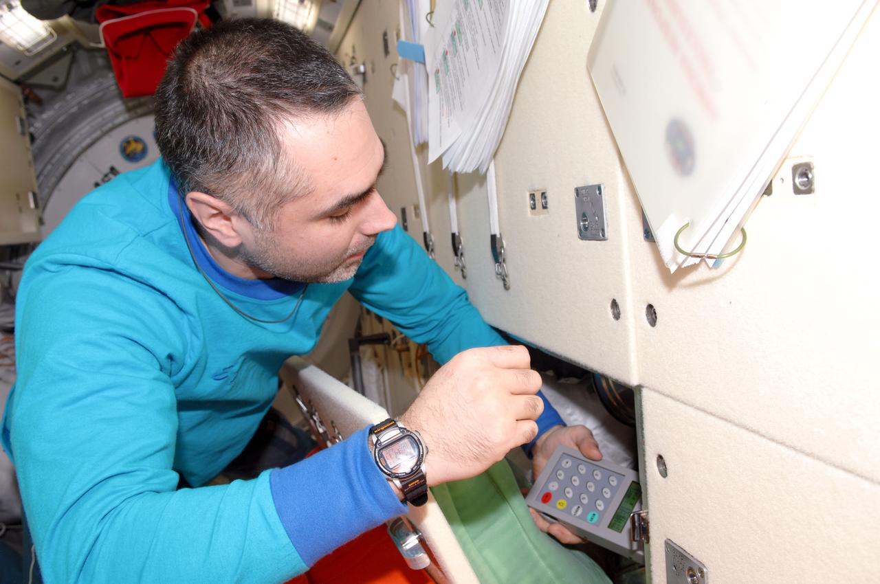
ISS034-E-021232 (10 Jan. 2013) --- Russian cosmonaut Evgeny Tarelkin, Expedition 34 flight engineer, looks at his watch while using the Liulin-5 Electronic Block behind a panel in the Rassvet Mini-Research Module 1 (MRM1) of the International Space Station.
iss068e037083 (Jan. 4, 2022) --- NASA astronaut and Expedition 68 Flight Engineer Josh Cassada swaps samples inside the Microgravity Science Glovebox for the Pore Formation and Mobility Investigation. The space physics study demonstrates a passive cooling system for electronic devices in microgravity using a micro-structured surface.

iss069e011049 (May 17, 2023) --- From left, Expedition 69 Flight Engineers Frank Rubio of NASA and Sultan Alneyadi of UAE (United Arab Emirates) return the station’s Treadmill 2 to its normal configuration inside the International Space Station's Tranquility module after an inspection and cleaning of its electronic components.
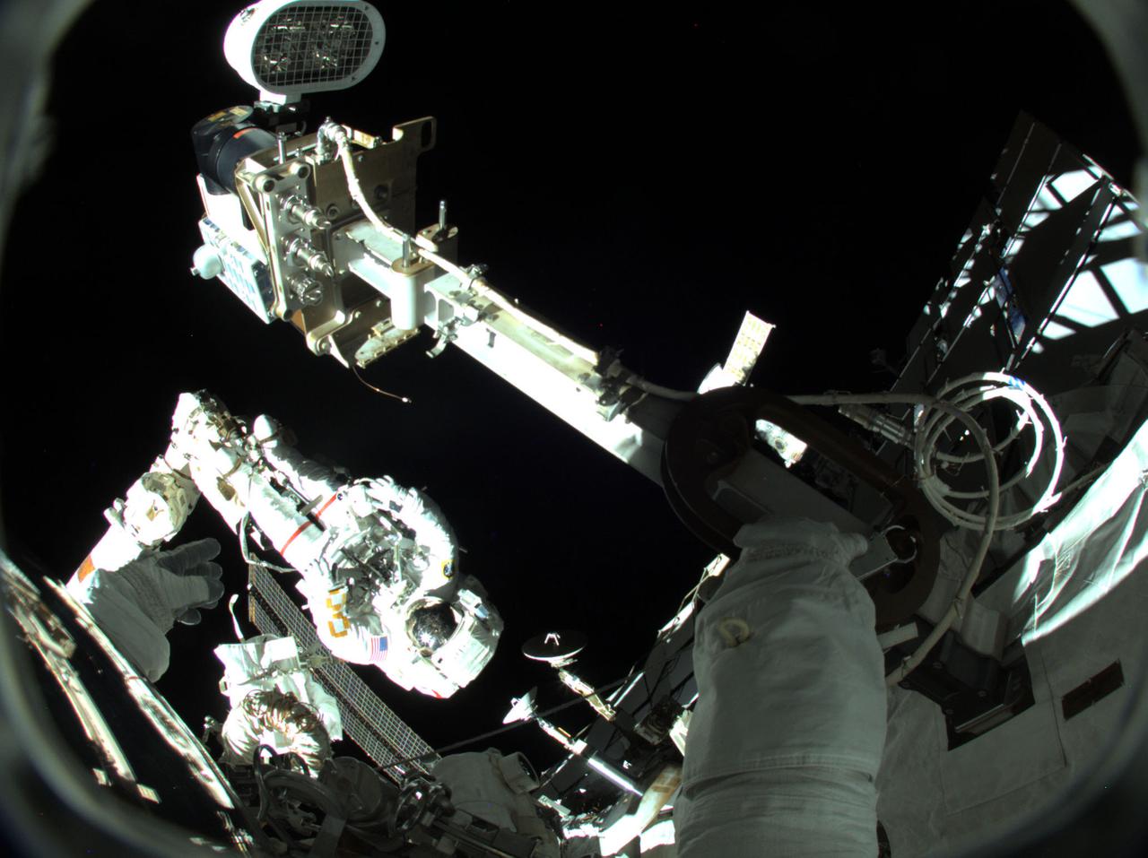
iss066e188275 (March 23, 20222) --- NASA astronaut and Expedition 66 Flight Engineer Raja Chari is pictured attached to the Canadarm2 robotic arm during a six-hour and 54-minute spacewalk to install thermal gear and electronic components on the International Space Station.
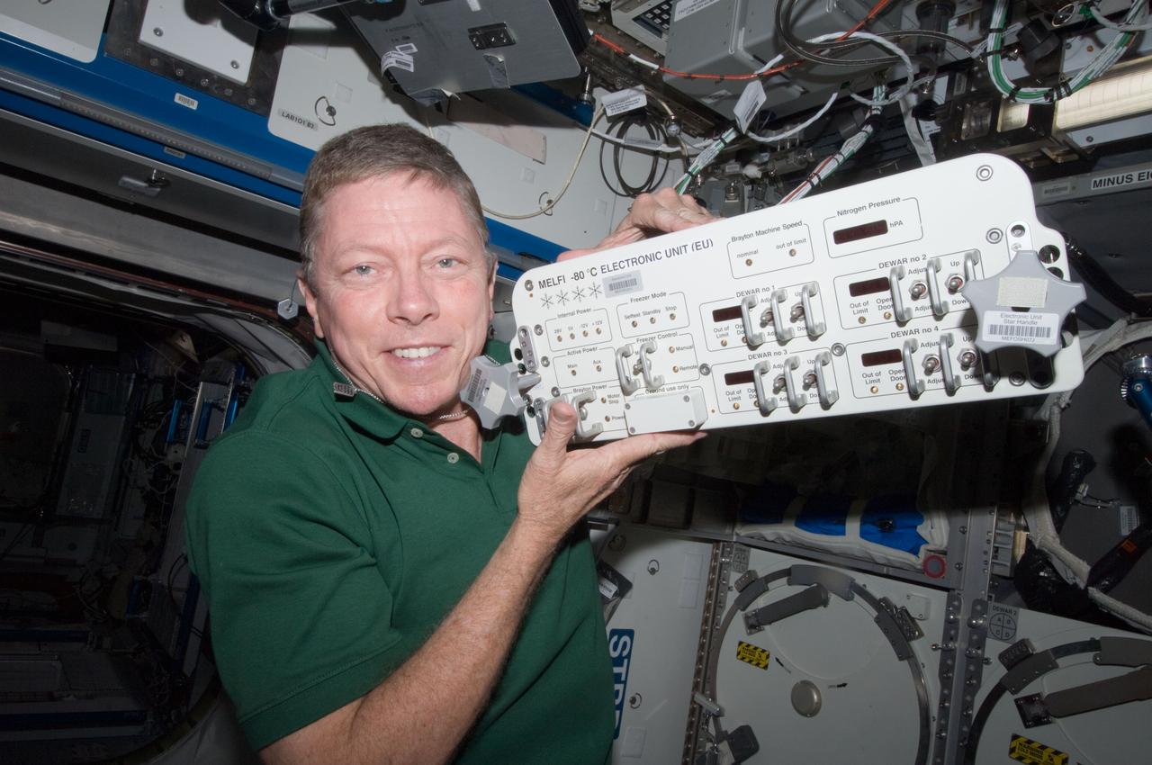
ISS028-E-013799 (1 July 2011) --- NASA astronaut Mike Fossum, Expedition 28 flight engineer, replaces a failed electronic unit for the Minus Eighty Laboratory Freezer for ISS 3 (MELFI-3) with a spare unit in the Kibo laboratory of the International Space Station.
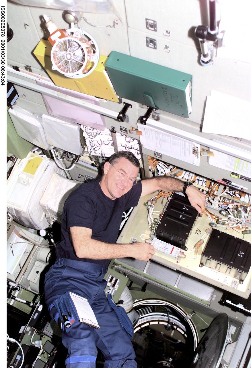
ISS002-E-5078 (30 March 2001) --- Astronaut James S. Voss, Expedition Two flight engineer, conducts electronics maintenance on the Zvezda / Service Module aboard the International Space Station (ISS). This image was recorded with a digital still camera.(ISS). This image was recorded with a digital still camera.
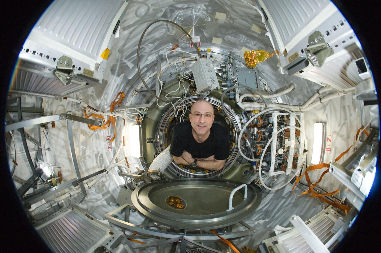
ISS031-E-035443 (15 May 2012) --- A fisheye lens attached to an electronic still camera was used to capture this image of NASA astronaut Don Pettit, Expedition 31 flight engineer, in the Progress 47 resupply vehicle docked to the International Space Station’s Pirs Docking Compartment.
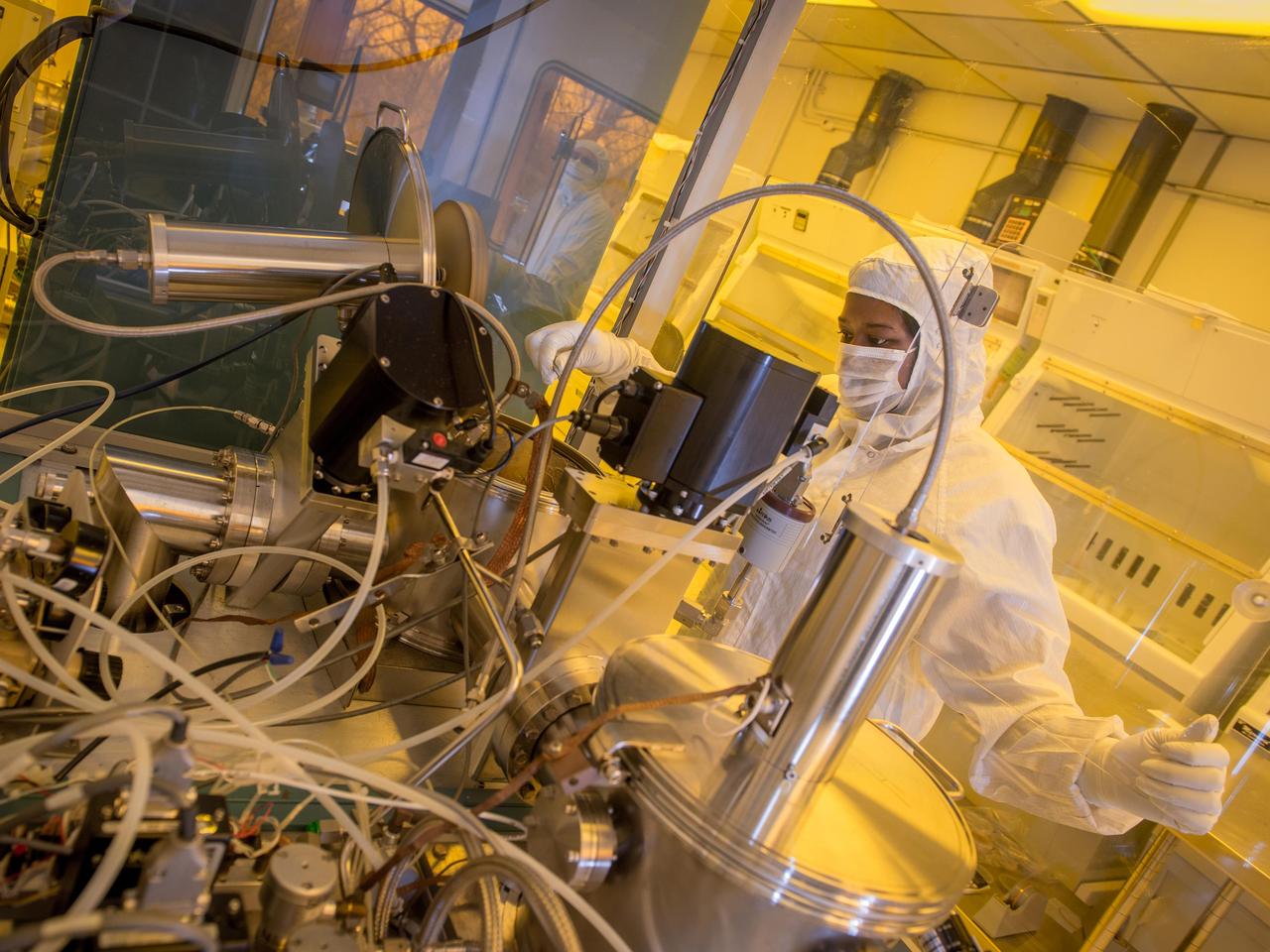
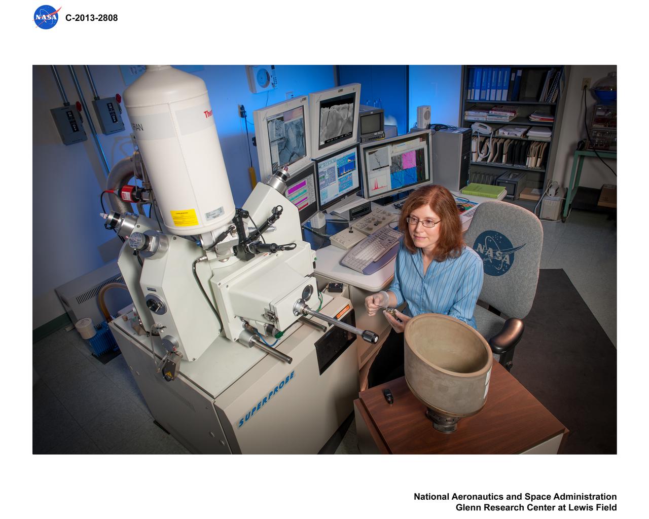
NASA Glenn technician Ariana Miller prepares an ultrahigh vacuum chamber used to test the materials used in silicon carbide based sensors and electronics that can operate at extremely high temperatures (500 degrees Celsius and higher) for applications such as sensor systems for aircraft engines and Venus exploration.
ISS031-E-030465 (12 May 2012) --- A fisheye lens attached to an electronic still camera was used to capture this image of NASA astronaut Don Pettit, Expedition 31 flight engineer, in the transfer compartment between the Zarya Functional Cargo Block (FGB) and the Zvezda Service Module of the International Space Station.
ISS034-E-021230 (10 Jan. 2013) --- Russian cosmonaut Evgeny Tarelkin, Expedition 34 flight engineer, uses the Liulin-5 Electronic Block behind a panel in the Rassvet Mini-Research Module 1 (MRM1) of the International Space Station.
ISS031-E-030486 (12 May 2012) --- A fisheye lens attached to an electronic still camera was used to capture this image of NASA astronaut Don Pettit, Expedition 31 flight engineer, in the Zvezda Service Module of the International Space Station.

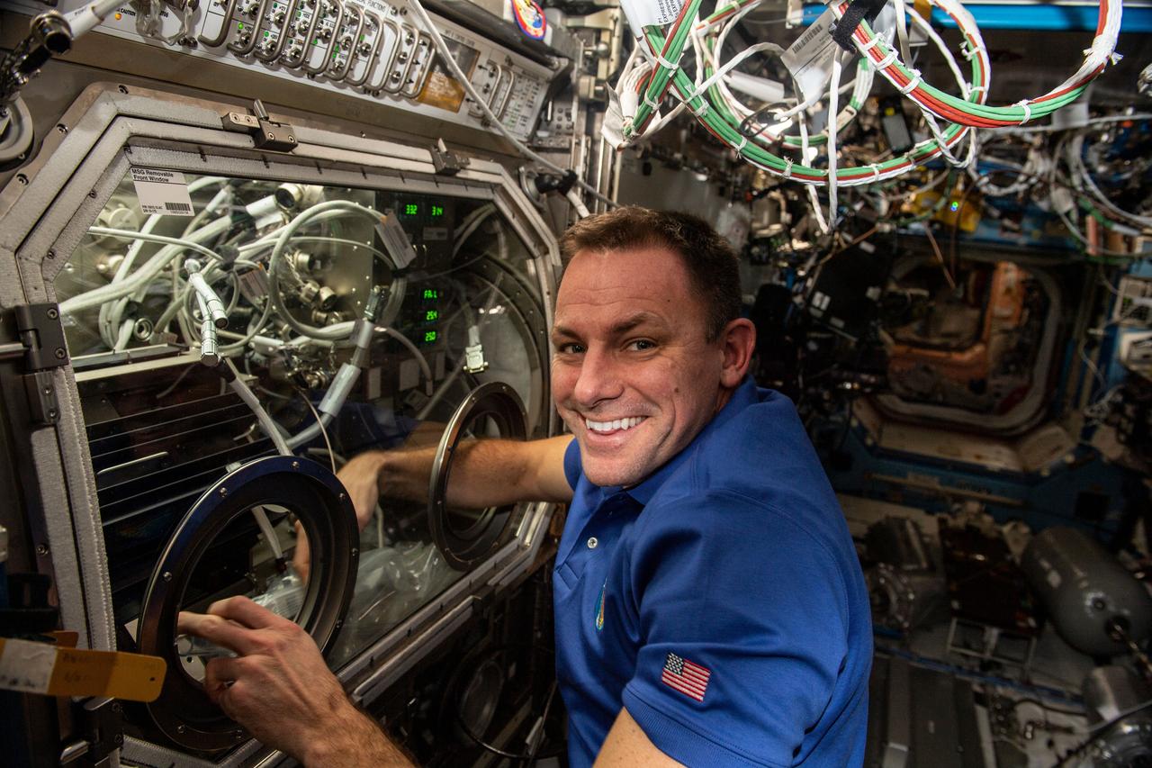
iss068e036994 (Jan. 4, 2023) --- NASA astronaut and Expedition 68 Flight Engineer Josh Cassada conducts research operations inside the Microgravity Science Glovebox for the Pore Formation and Mobility Investigation. The space physics study demonstrates a passive cooling system for electronic devices in microgravity using a micro-structured surface.

iss066e175213 (March 23, 2022) --- NASA astronaut and Expedition 66 Flight Engineer Raja Chari is pictured attached to the Canadarm2 robotic arm during a six-hour and 54-minute spacewalk to install thermal gear and electronic components on the International Space Station.
iss066e174345 (March 23, 2022) --- ESA (European Space Agency) astronaut and Expediution 66 Flight Engineer Matthias Maurer spacesuit is pictured in his U.S. spacesuit prior to beginning a spacewalk to install thermal gear and electronics components on the International Space Station.
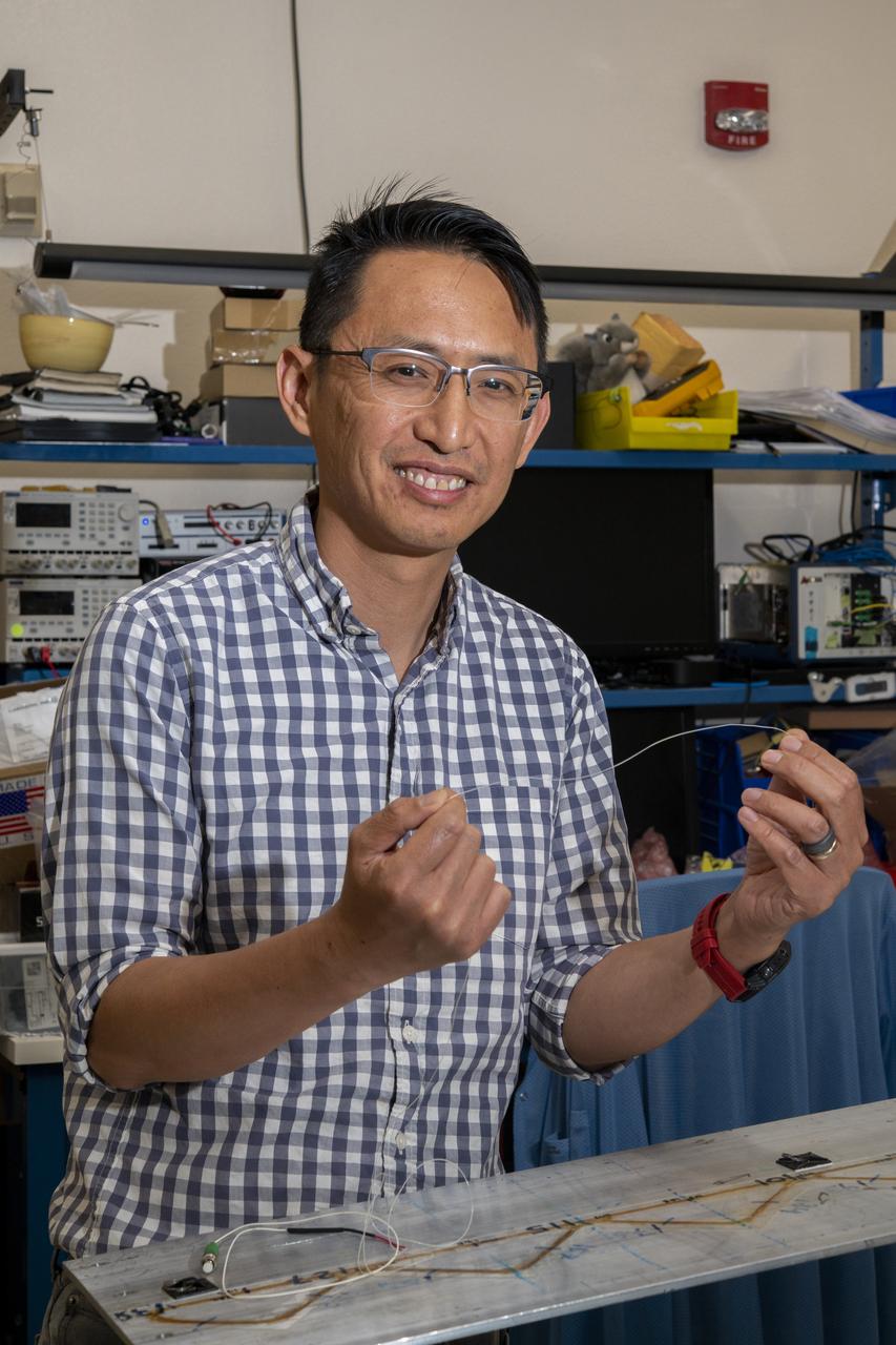
NASA’s Armstrong Flight Research Center’s FOSS, Fiber Optic Sensing System, recently supported tests of a system designed to turn oxygen into liquid oxygen, a component of rocket fuel. Patrick Chan, electronics engineer, and NASA Armstrong’s FOSS portfolio project manager, shows fiber like that used in the testing.
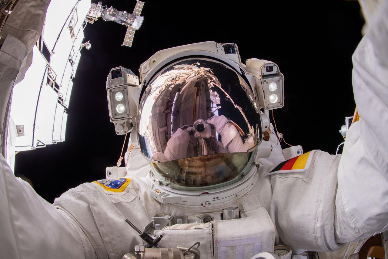
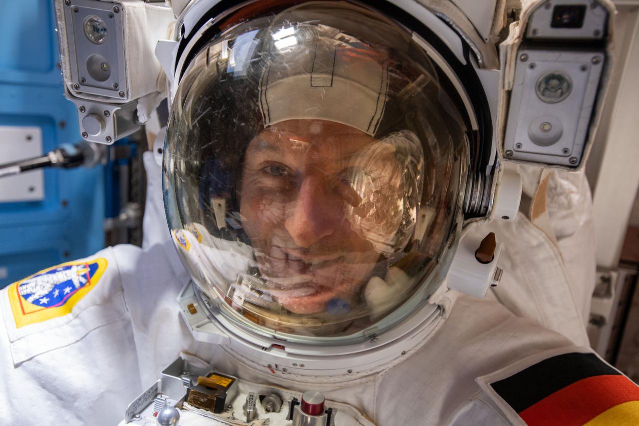
iss066e175249 (March 23, 2022) --- ESA (European Space Agency) astronaut and Expedition 66 Flight Engineer Matthias Maurer points the camera toward himself and takes a "space-selfie" during a six-hour and 54-minute spacewalk to install thermal gear and electronic components on the International Space Station.
iss068e028262 (Dec. 9, 2022) --- NASA astronaut and Expedition 68 Flight Engineer Frank Rubio exchanges samples inside the Microgravity Science Glovebox for the Pore Formation and Mobility Investigation. The space physics study demonstrates a passive cooling system for electronic devices in microgravity using a micro-structured surface.
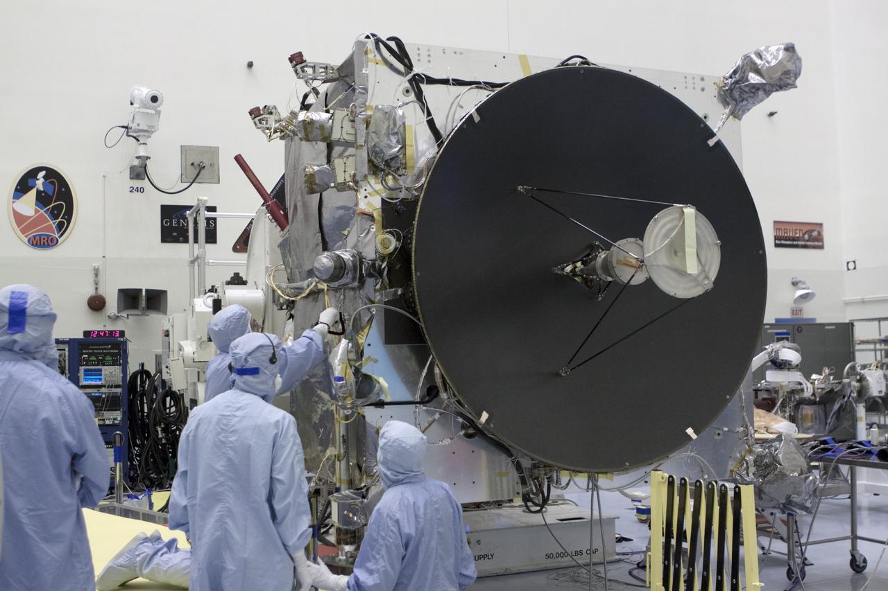
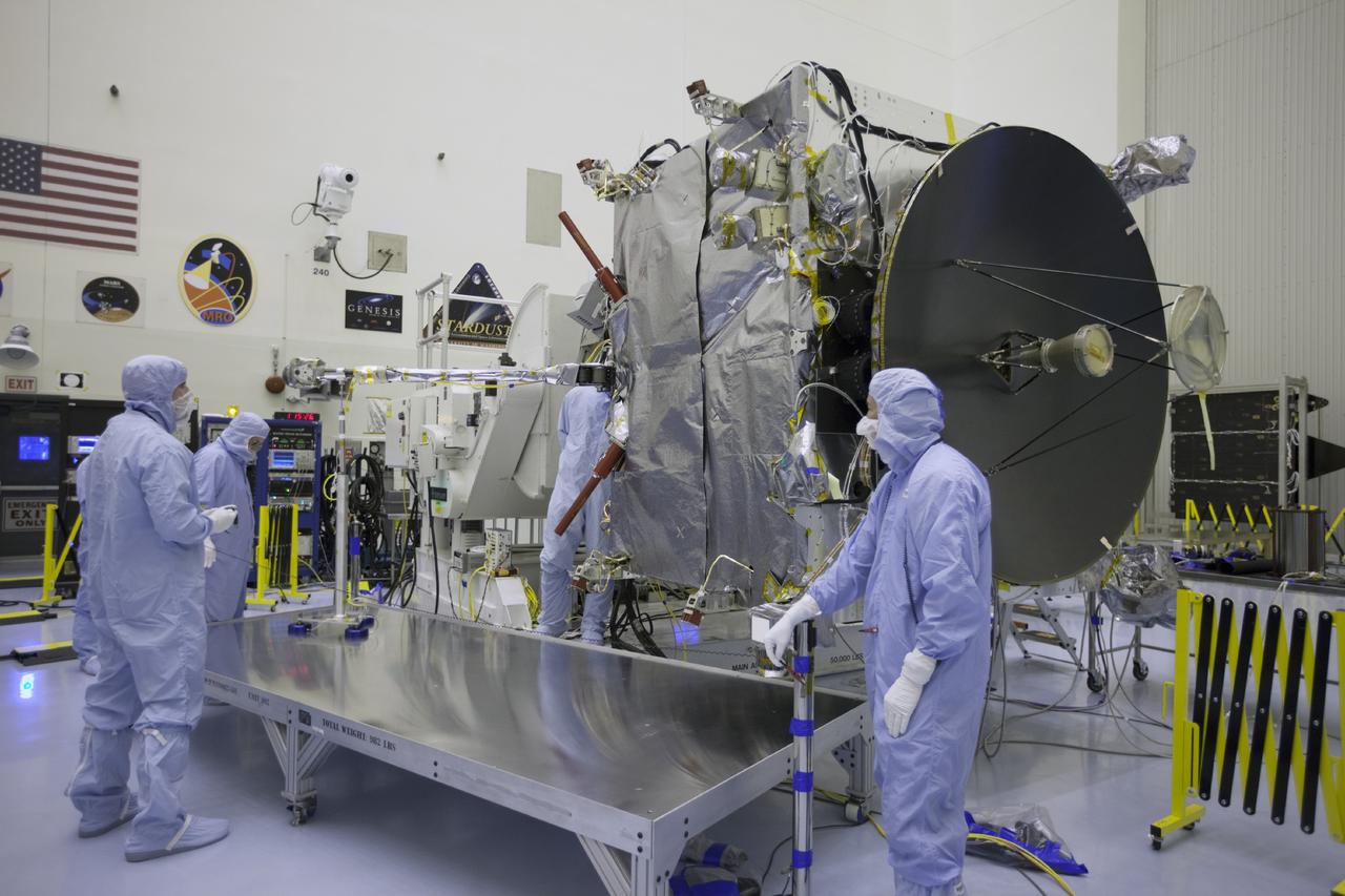
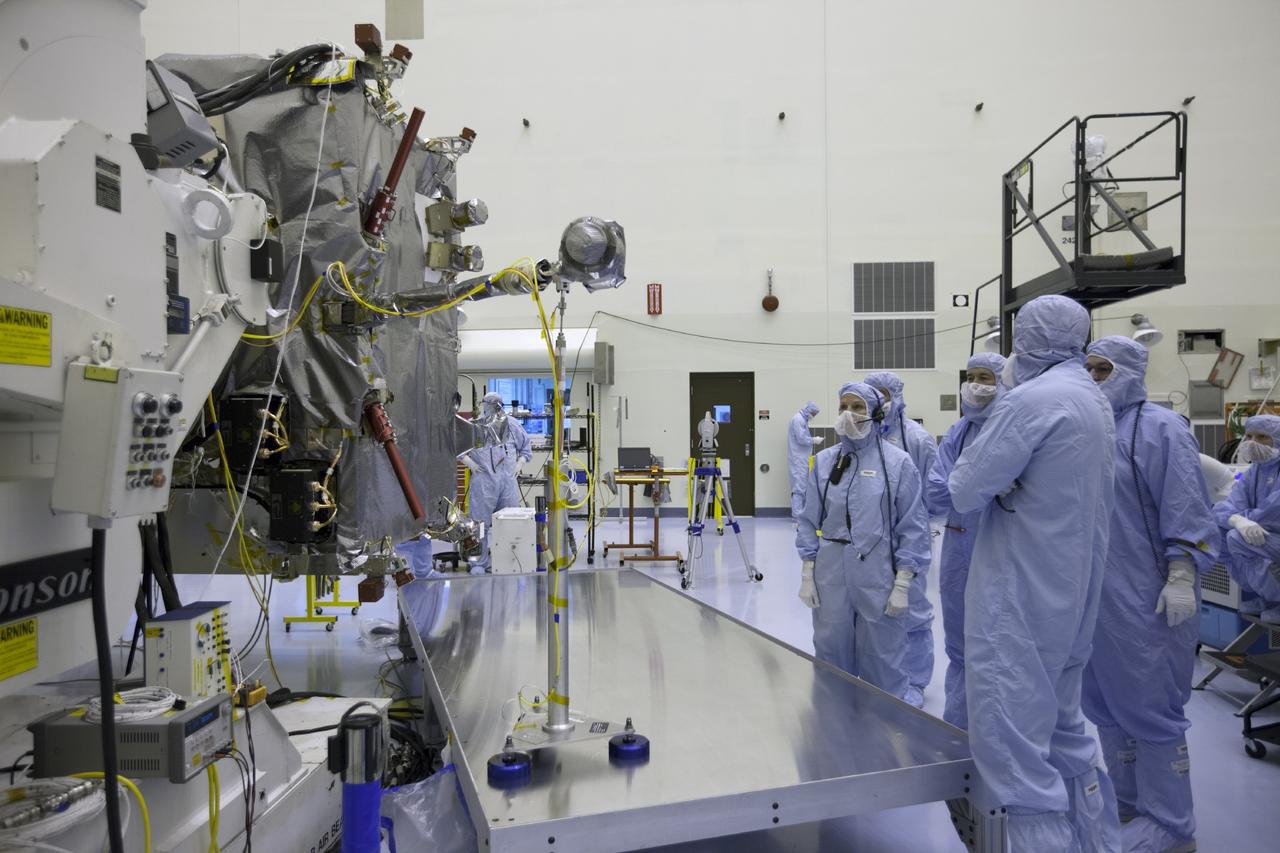
CAPE CANAVERAL, Fla. – Inside the Payload Hazardous Servicing Facility at NASA's Kennedy Space Center in Florida, engineers and technicians deploy the Solar Wind Electron Analyzer boom on the Mars Atmosphere and Volatile Evolution, or MAVEN, spacecraft. The analyzer will measure the solar wind and electrons in the ionosphere of the Red Planet. MAVEN is being prepared for its scheduled launch in November from Cape Canaveral Air Force Station, Fla. atop a United Launch Alliance Atlas V rocket. Positioned in an orbit above the Red Planet, MAVEN will study the upper atmosphere of Mars in unprecedented detail. For more information, visit: http://www.nasa.gov/mission_pages/maven/main/index.html Photo credit: NASA/Kim Shiflett
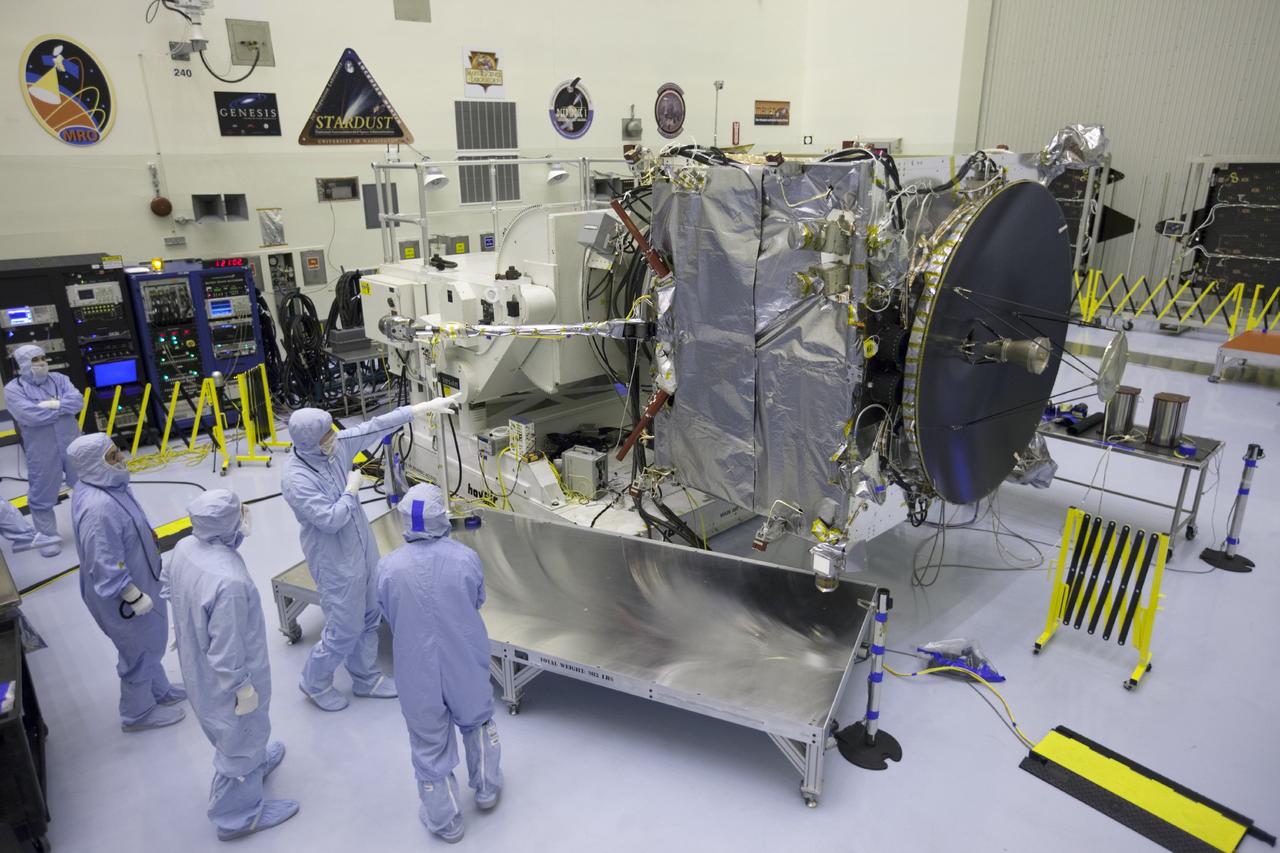
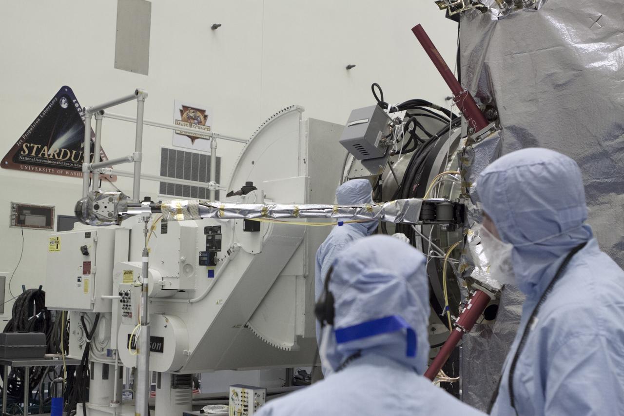
CAPE CANAVERAL, Fla. – Inside the Payload Hazardous Servicing Facility at NASA's Kennedy Space Center in Florida, engineers and technicians prepare to deploy the Solar Wind Electron Analyzer boom on the Mars Atmosphere and Volatile Evolution, or MAVEN, spacecraft. The analyzer will measure the solar wind and electrons in the ionosphere of the Red Planet. MAVEN is being prepared for its scheduled launch in November from Cape Canaveral Air Force Station, Fla. atop a United Launch Alliance Atlas V rocket. Positioned in an orbit above the Red Planet, MAVEN will study the upper atmosphere of Mars in unprecedented detail. For more information, visit: http://www.nasa.gov/mission_pages/maven/main/index.html Photo credit: NASA/Kim Shiflett
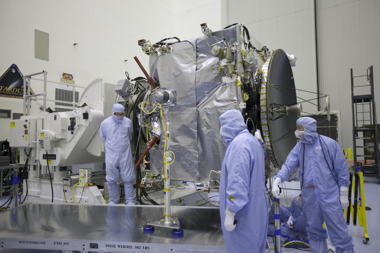
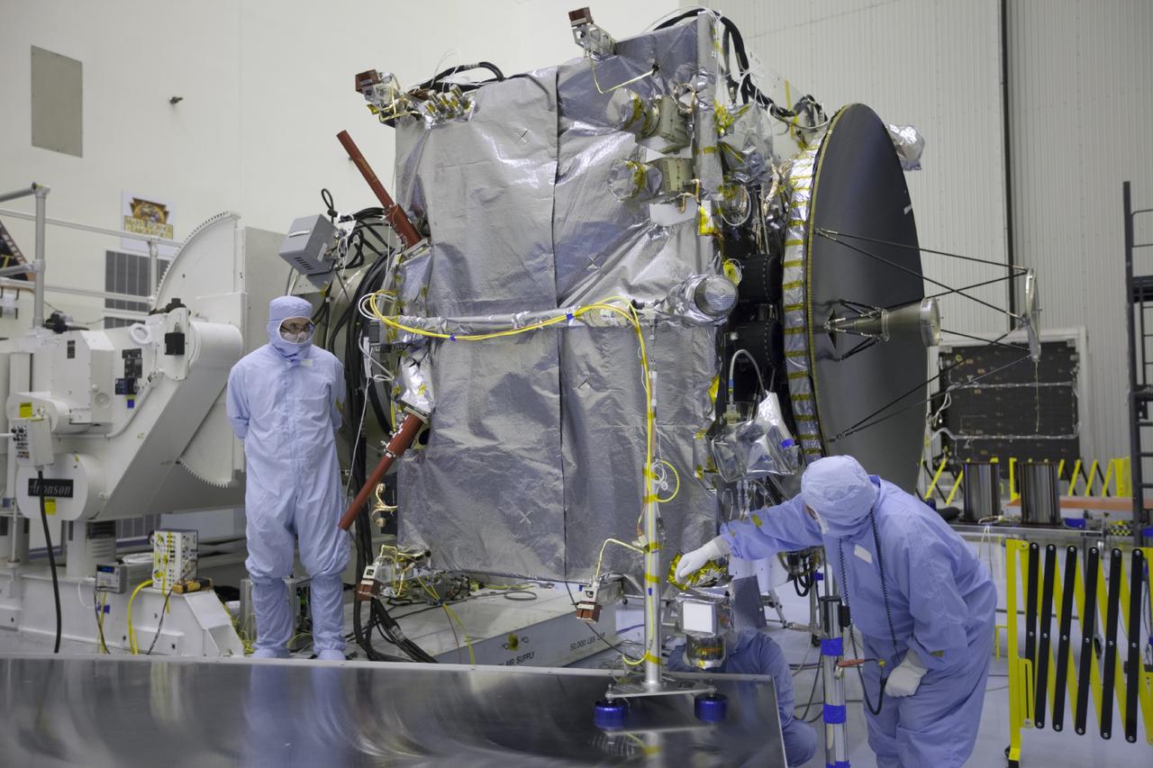
CAPE CANAVERAL, Fla. – Inside the Payload Hazardous Servicing Facility at NASA's Kennedy Space Center in Florida, engineers and technicians deploy the Solar Wind Electron Analyzer boom on the Mars Atmosphere and Volatile Evolution, or MAVEN, spacecraft. The analyzer will measure the solar wind and electrons in the ionosphere of the Red Planet. MAVEN is being prepared for its scheduled launch in November from Cape Canaveral Air Force Station, Fla. atop a United Launch Alliance Atlas V rocket. Positioned in an orbit above the Red Planet, MAVEN will study the upper atmosphere of Mars in unprecedented detail. For more information, visit: http://www.nasa.gov/mission_pages/maven/main/index.html Photo credit: NASA/Kim Shiflett
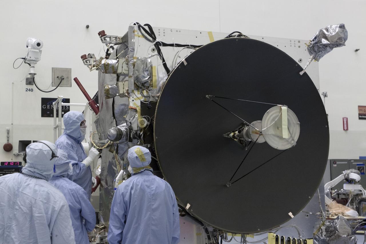
CAPE CANAVERAL, Fla. – Inside the Payload Hazardous Servicing Facility at NASA's Kennedy Space Center in Florida, engineers and technicians deploy the Solar Wind Electron Analyzer boom on the Mars Atmosphere and Volatile Evolution, or MAVEN, spacecraft. The analyzer will measure the solar wind and electrons in the ionosphere of the Red Planet. MAVEN is being prepared for its scheduled launch in November from Cape Canaveral Air Force Station, Fla. atop a United Launch Alliance Atlas V rocket. Positioned in an orbit above the Red Planet, MAVEN will study the upper atmosphere of Mars in unprecedented detail. For more information, visit: http://www.nasa.gov/mission_pages/maven/main/index.html Photo credit: NASA/Kim Shiflett
CAPE CANAVERAL, Fla. – Inside the Payload Hazardous Servicing Facility at NASA's Kennedy Space Center in Florida, engineers and technicians deploy the Solar Wind Electron Analyzer boom on the Mars Atmosphere and Volatile Evolution, or MAVEN, spacecraft. The analyzer will measure the solar wind and electrons in the ionosphere of the Red Planet. MAVEN is being prepared for its scheduled launch in November from Cape Canaveral Air Force Station, Fla. atop a United Launch Alliance Atlas V rocket. Positioned in an orbit above the Red Planet, MAVEN will study the upper atmosphere of Mars in unprecedented detail. For more information, visit: http://www.nasa.gov/mission_pages/maven/main/index.html Photo credit: NASA/Kim Shiflett
CAPE CANAVERAL, Fla. – Inside the Payload Hazardous Servicing Facility at NASA's Kennedy Space Center in Florida, engineers and technicians prepare to deploy the Solar Wind Electron Analyzer boom on the Mars Atmosphere and Volatile Evolution, or MAVEN, spacecraft. The analyzer will measure the solar wind and electrons in the ionosphere of the Red Planet. MAVEN is being prepared for its scheduled launch in November from Cape Canaveral Air Force Station, Fla. atop a United Launch Alliance Atlas V rocket. Positioned in an orbit above the Red Planet, MAVEN will study the upper atmosphere of Mars in unprecedented detail. For more information, visit: http://www.nasa.gov/mission_pages/maven/main/index.html Photo credit: NASA/Kim Shiflett
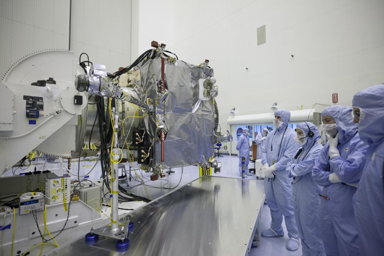
CAPE CANAVERAL, Fla. – Inside the Payload Hazardous Servicing Facility at NASA's Kennedy Space Center in Florida, engineers and technicians deploy the Solar Wind Electron Analyzer boom on the Mars Atmosphere and Volatile Evolution, or MAVEN, spacecraft. The analyzer will measure the solar wind and electrons in the ionosphere of the Red Planet. MAVEN is being prepared for its scheduled launch in November from Cape Canaveral Air Force Station, Fla. atop a United Launch Alliance Atlas V rocket. Positioned in an orbit above the Red Planet, MAVEN will study the upper atmosphere of Mars in unprecedented detail. For more information, visit: http://www.nasa.gov/mission_pages/maven/main/index.html Photo credit: NASA/Kim Shiflett
CAPE CANAVERAL, Fla. – Inside the Payload Hazardous Servicing Facility at NASA's Kennedy Space Center in Florida, engineers and technicians deploy the Solar Wind Electron Analyzer boom on the Mars Atmosphere and Volatile Evolution, or MAVEN, spacecraft. The analyzer will measure the solar wind and electrons in the ionosphere of the Red Planet. MAVEN is being prepared for its scheduled launch in November from Cape Canaveral Air Force Station, Fla. atop a United Launch Alliance Atlas V rocket. Positioned in an orbit above the Red Planet, MAVEN will study the upper atmosphere of Mars in unprecedented detail. For more information, visit: http://www.nasa.gov/mission_pages/maven/main/index.html Photo credit: NASA/Kim Shiflett
CAPE CANAVERAL, Fla. – Inside the Payload Hazardous Servicing Facility at NASA's Kennedy Space Center in Florida, engineers and technicians deploy the Solar Wind Electron Analyzer boom on the Mars Atmosphere and Volatile Evolution, or MAVEN, spacecraft. The analyzer will measure the solar wind and electrons in the ionosphere of the Red Planet. MAVEN is being prepared for its scheduled launch in November from Cape Canaveral Air Force Station, Fla. atop a United Launch Alliance Atlas V rocket. Positioned in an orbit above the Red Planet, MAVEN will study the upper atmosphere of Mars in unprecedented detail. For more information, visit: http://www.nasa.gov/mission_pages/maven/main/index.html Photo credit: NASA/Kim Shiflett
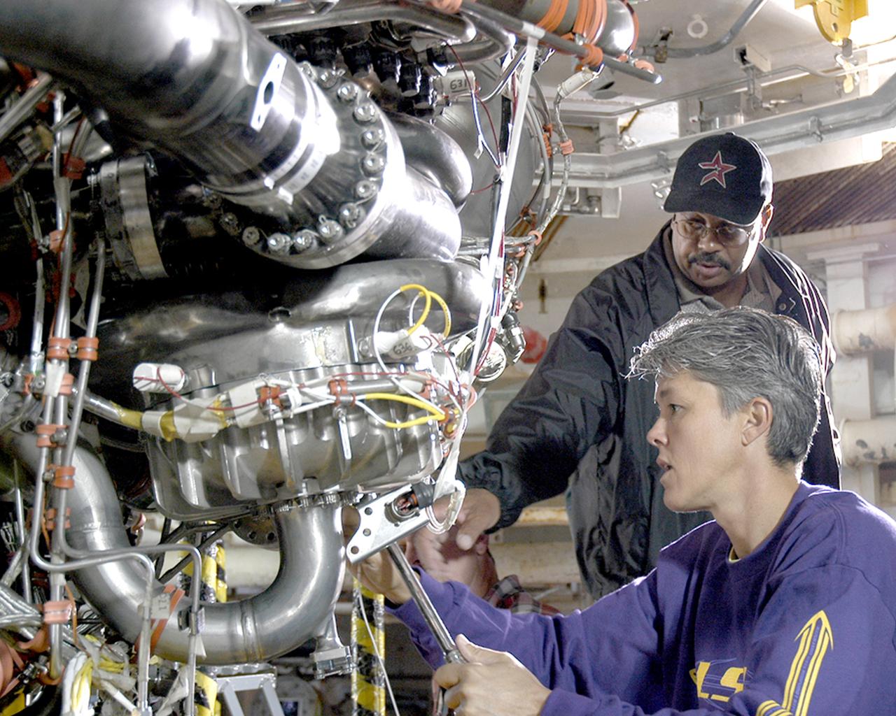
Alvin Pittman Sr., lead electronics technician with Pratt & Whitney Rocketdyne, and Janine Cuevas, a mechanical technician with PWR, perform final preparations on the space shuttle main engine tested Oct. 25, 2005, at NASA's Stennis Space Center. It was the first main engine test since Hurricane Katrina hit the Gulf Coast on Aug. 29.
iss068e016422 (Oct. 12, 2022) --- NASA astronaut and Expedition 68 Flight Engineer Jessica Watkins works with Mochii, a miniature scanning electron microscope (SEM) with spectroscopy to conduct real-time, on-site imaging and compositional measurements of particles on the International Space Station (ISS). Such particles can cause vehicle and equipment malfunctions and threaten crew health, but currently, samples must be returned to Earth for analysis, leaving crew and vehicle at risk. Mochii also provides a powerful new analysis platform to support novel microgravity science and engineering.
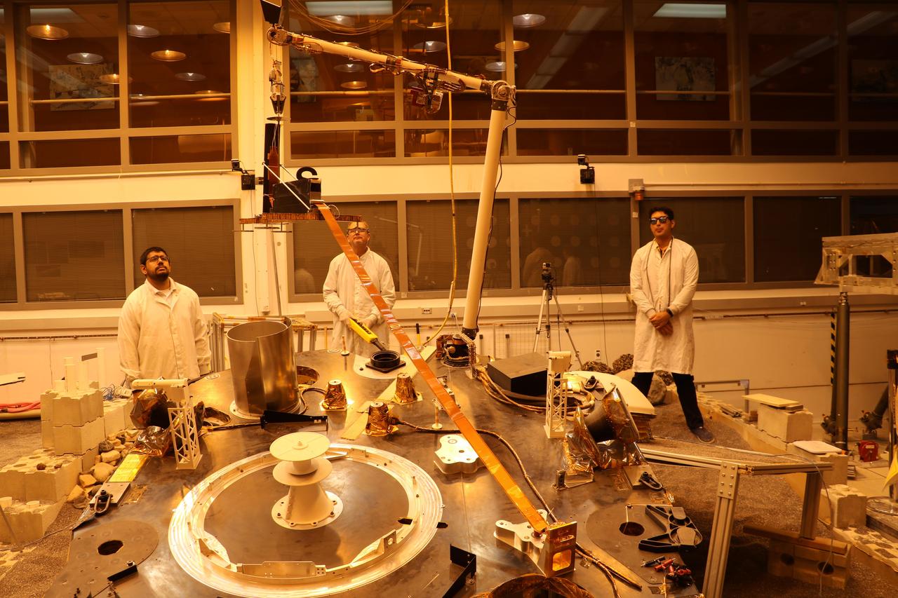
An engineering version of the robotic arm on NASA's InSight mission lifts the engineering version of the Heat Flow and Physical Properties Probe (HP3) at NASA's Jet Propulsion Laboratory. This test was conducted by InSight team members in a Mars-like environment, including reddish lighting, to simulate conditions InSight will encounter on the Red Planet. The orange tape-like tail behind HP3 is a tether that connects the HP3 support structure to the instrument's back-end electronics box on the lander. https://photojournal.jpl.nasa.gov/catalog/PIA22807
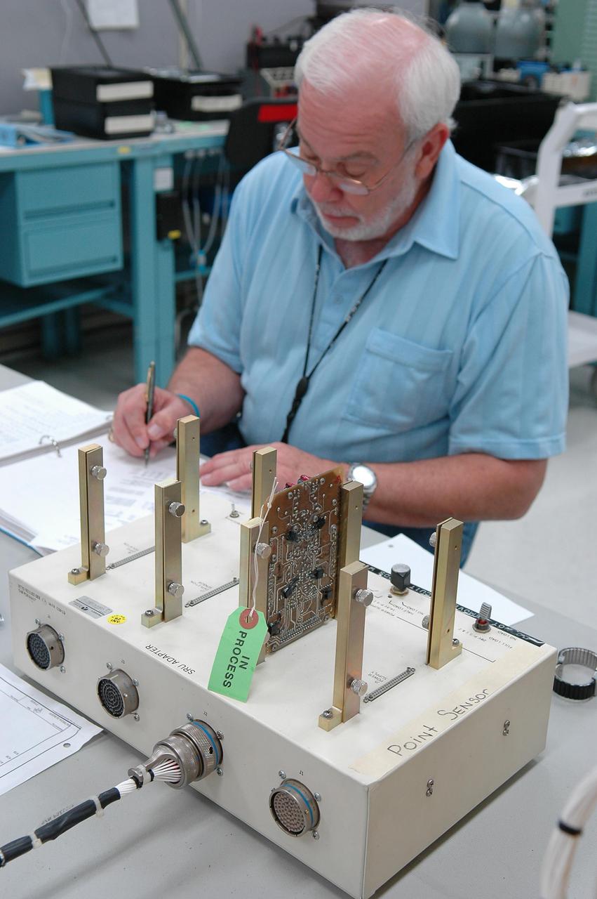
KENNEDY SPACE CENTER, FLA. - Lloyd Pierce, a NASA test engineer, checks electronic components related to the faulty sensor readings in the liquid hydrogen tank low-level fuel cut-off sensor. The sensor failed a routine prelaunch check during the launch July 13, causing mission managers to scrub Discovery's first launch attempt. The sensor protects the Shuttle's main engines by triggering their shutdown in the event fuel runs unexpectedly low. The sensor is one of four inside the liquid hydrogen section of the External Tank (ET).
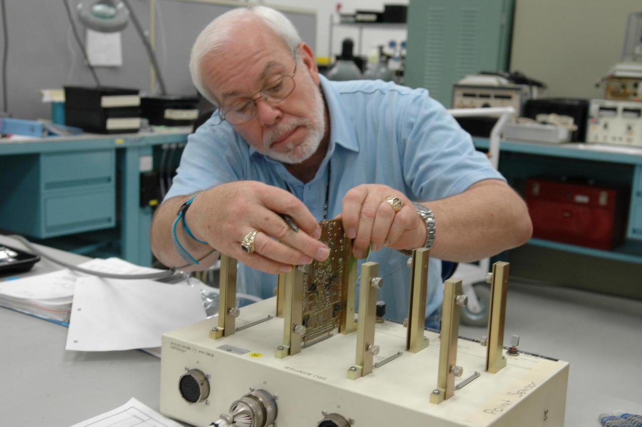
KENNEDY SPACE CENTER, FLA. - Lloyd Pierce, a NASA test engineer, checks electronic components related to the faulty sensor readings in the liquid hydrogen tank low-level fuel cut-off sensor. The sensor failed a routine prelaunch check during the launch July 13, causing mission managers to scrub Discovery's first launch attempt. The sensor protects the Shuttle's main engines by triggering their shutdown in the event fuel runs unexpectedly low. The sensor is one of four inside the liquid hydrogen section of the External Tank (ET).
ISS036-E-022134 (20 July 2013) --- A fisheye lens attached to an electronic still camera was used to capture this image of NASA astronaut Karen Nyberg, Expedition 36 flight engineer, holding a digital still camera in the Tranquility node of the International Space Station. European Space Agency astronaut Luca Parmitano, flight engineer, is at lower left.

KENNEDY SPACE CENTER, FLA. - Lloyd Pierce, a NASA test engineer, checks electronic components related to the faulty sensor readings in the liquid hydrogen tank low-level fuel cut-off sensor. The sensor failed a routine prelaunch check during the launch July 13, causing mission managers to scrub Discovery's first launch attempt. The sensor protects the Shuttle's main engines by triggering their shutdown in the event fuel runs unexpectedly low. The sensor is one of four inside the liquid hydrogen section of the External Tank (ET).
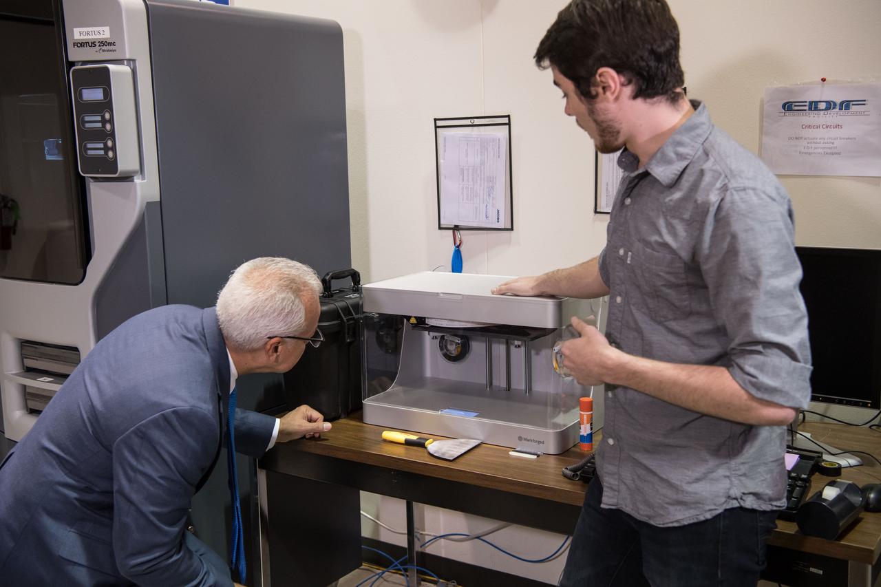
A Jacobs engineer shows NASA Chief Technologist Douglas Terrier how the company uses 3-D printers to create inexpensive physical models of new electronically designed hardware. Date: 08-10-2017 Location: B1 & Jacobs Engineering Subject: NASA Acting Chief Technology Officer Douglas Terrier Tours JSC and Jacobs Photographer: David DeHoyos
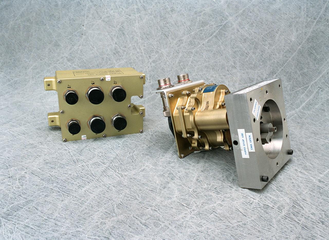
The electro-mechanical actuator, a new electronics technology, is an electronic system that provides the force needed to move valves that control the flow of propellant to the engine. It is proving to be advantageous for the main propulsion system plarned for a second generation reusable launch vehicle. Hydraulic actuators have been used successfully in rocket propulsion systems. However, they can leak when high pressure is exerted on such a fluid-filled hydraulic system. Also, hydraulic systems require significant maintenance and support equipment. The electro-mechanical actuator is proving to be low maintenance and the system weighs less than a hydraulic system. The electronic controller is a separate unit powering the actuator. Each actuator has its own control box. If a problem is detected, it can be replaced by simply removing one defective unit. The hydraulic systems must sustain significant hydraulic pressures in a rocket engine regardless of demand. The electro-mechanical actuator utilizes power only when needed. A goal of the Second Generation Reusable Launch Vehicle Program is to substantially improve safety and reliability while reducing the high cost of space travel. The electro-mechanical actuator was developed by the Propulsion Projects Office of the Second Generation Reusable Launch Vehicle Program at the Marshall Space Flight Center.
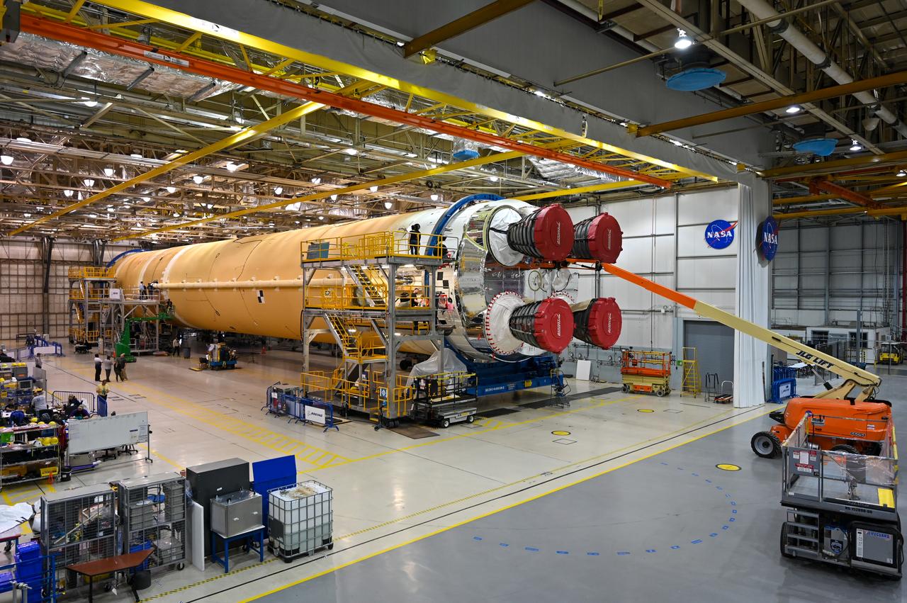
This image shows the core stage for NASA’s Space Launch System (SLS) rocket without scaffolding at NASA’s Michoud Assembly Facility in New Orleans. Assembly and integration of the core stage and its four RS-25 engines has been a collaborative, multistep process for NASA and its partners Boeing, the core stage lead contractor, and Aerojet Rocketdyne, the RS-25 engines lead contractor. NASA and the contractor team used the scaffolding previously positioned around the 212-foot core stage to assess the stage’s inside and check out the electronic systems distributed throughout the stage, including avionics and propulsion systems, that will enable the stage to operate during launch and flight. The team will continue to check out these systems at NASA’s Stennis Space Center near Bay St. Louis, Mississippi, where it will undergo the core stage Green Run testing.
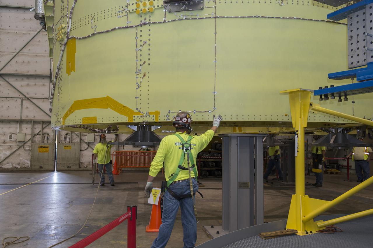
NASA engineers install test hardware for the agency's new heavy lift rocket, the Space Launch System, into a newly constructed 50-foot structural test stand at NASA's Marshall Space Flight Center. In the stand, hydraulic cylinders will be electronically controlled to push, pull, twist and bend the test article with millions of pounds of force. Engineers will record and analyze over 3,000 channels of data for each test case to verify the capabilities of the engine section and validate that the design and analysis models accurately predict the amount of loads the core stage can withstand during launch and ascent. The engine section, recently delivered via NASA's barge Pegasus from NASA's Michoud Assembly Facility, is the first of four core stage structural test articles scheduled to be delivered to Marshall for testing. The engine section, located at the bottom of SLS's massive core stage, will house the rocket's four RS-25 engines and be an attachment point for the two solid rocket boosters.
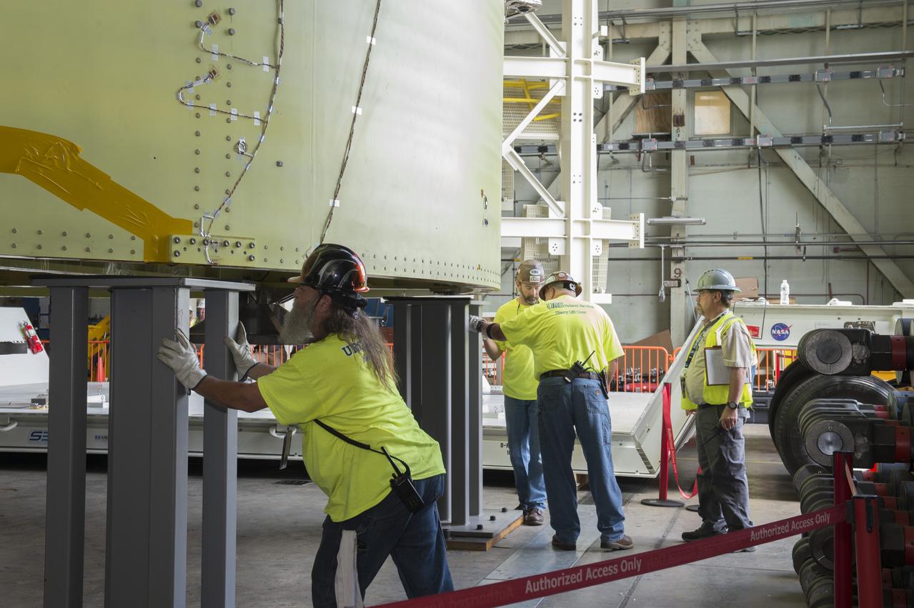
NASA engineers install test hardware for the agency's new heavy lift rocket, the Space Launch System, into a newly constructed 50-foot structural test stand at NASA's Marshall Space Flight Center. In the stand, hydraulic cylinders will be electronically controlled to push, pull, twist and bend the test article with millions of pounds of force. Engineers will record and analyze over 3,000 channels of data for each test case to verify the capabilities of the engine section and validate that the design and analysis models accurately predict the amount of loads the core stage can withstand during launch and ascent. The engine section, recently delivered via NASA's barge Pegasus from NASA's Michoud Assembly Facility, is the first of four core stage structural test articles scheduled to be delivered to Marshall for testing. The engine section, located at the bottom of SLS's massive core stage, will house the rocket's four RS-25 engines and be an attachment point for the two solid rocket boosters.