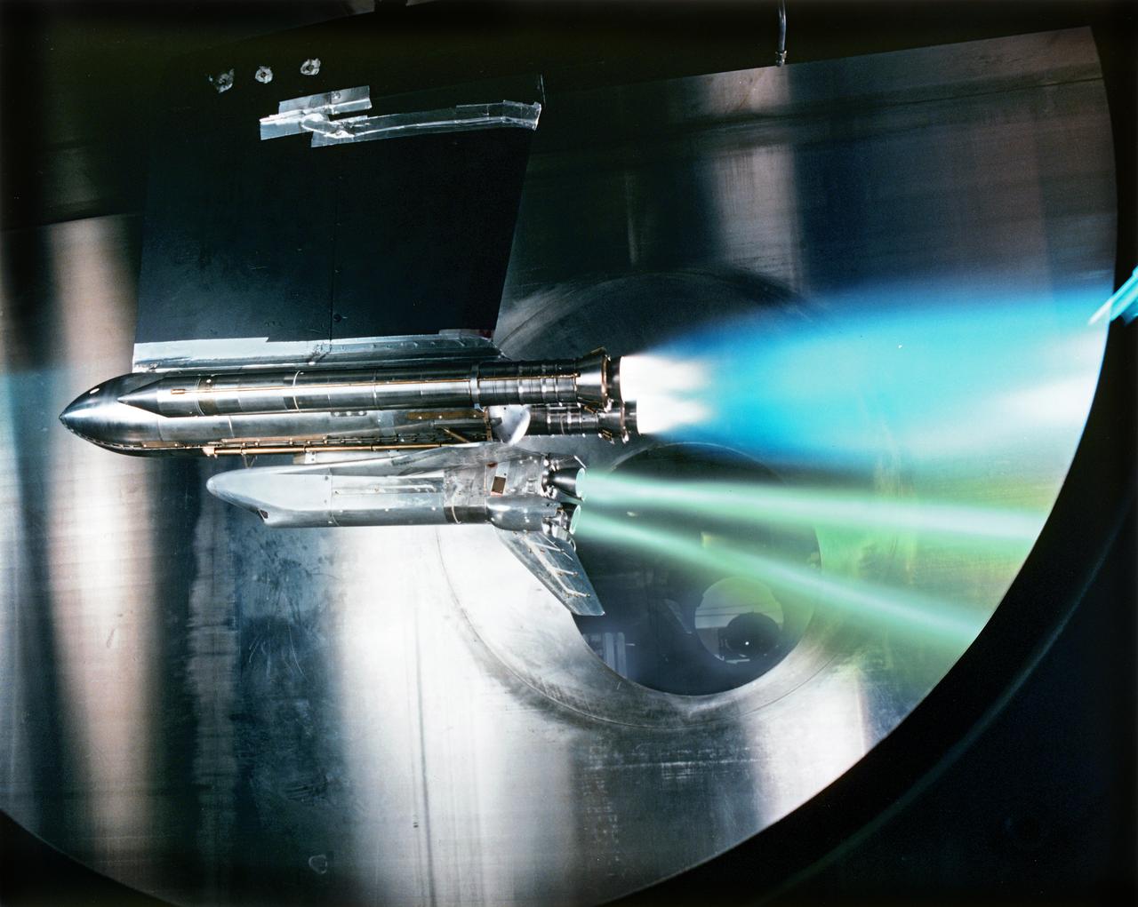
SHUTTLE ENGINE OUT TEST done after the Space Shuttle Challenger disaster. This was part of the investigation after the Challenger accident

This test conducted in May 1988 shows what happens during launch if a space shuttle main engine fails. The test was conducted in the 10X10 supersonic wind tunnel at the John H. Glenn Research Center.
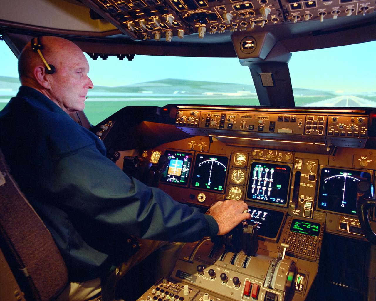
NASA research pilot Gordon Fullerton checked out how the PCA software worked in the multi-engine simulator at NASA Ames before fight-testing PCA in an MD-11.
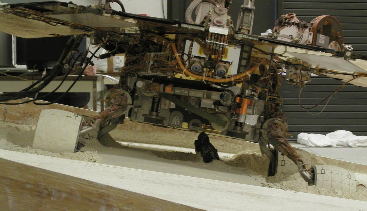
With a slope of about 10 degrees and a pointy rock under the test rover belly, this sandbox setup at NASA JPL, is ready for engineers to use the test rover to assess possible moves for getting Mars rover Spirit out of a patch of loose Martian soil.

Steam blasts out of the A-2 Test Stand at Stennis Space Center on Oct. 22 as engineers begin a certification test on engine 2061, the last space shuttle main flight engine scheduled to be built. Since 1975, Stennis has tested every space shuttle main engine used in the program - about 50 engines in all. Those engines have powered more than 120 shuttle missions - and no mission has failed as a result of engine malfunction. For the remainder of 2008 and throughout 2009, Stennis will continue testing of various space shuttle main engine components.
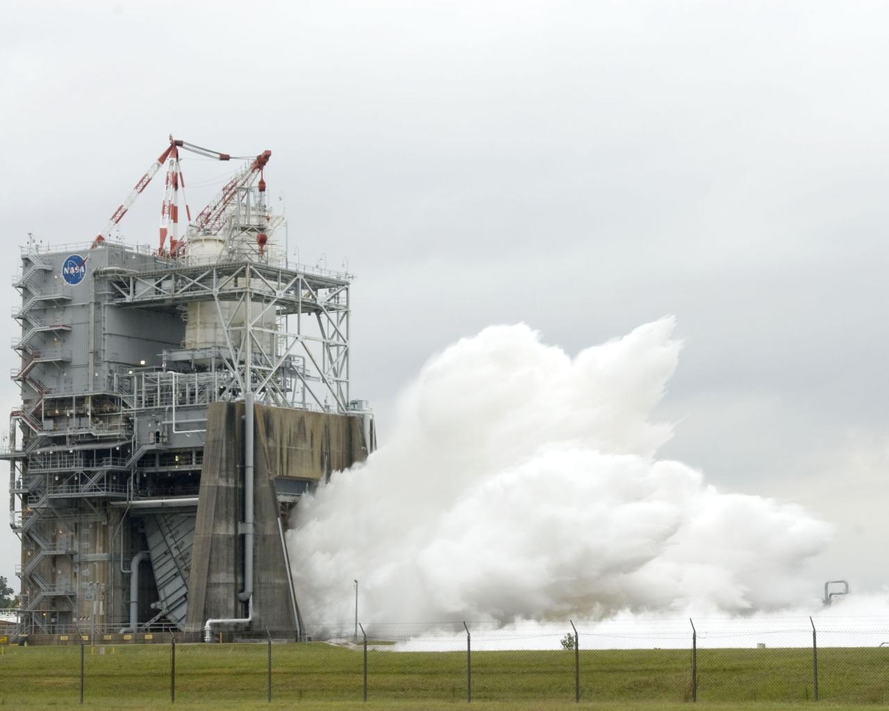
Steam blasts out of the A-2 Test Stand at Stennis Space Center on Oct. 22 as engineers begin a certification test on engine 2061, the last space shuttle main flight engine scheduled to be built. Since 1975, Stennis has tested every space shuttle main engine used in the program - about 50 engines in all. Those engines have powered more than 120 shuttle missions - and no mission has failed as a result of engine malfunction. For the remainder of 2008 and throughout 2009, Stennis will continue testing of various space shuttle main engine components.
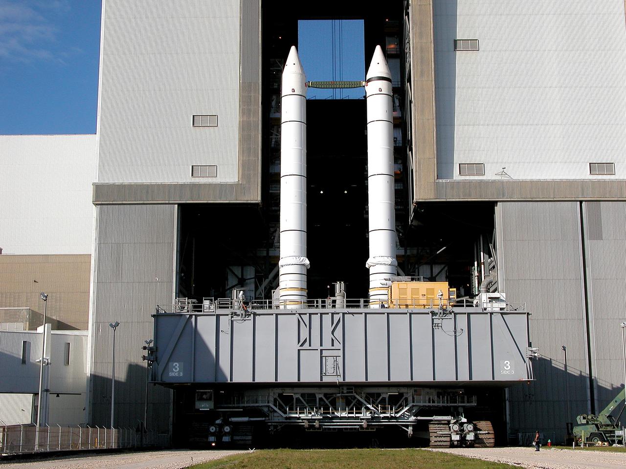
KENNEDY SPACE CENTER, FLA. - As the crawler transporter slowly moves the Mobile Launcher Platform (MLP) out of the Vehicle Assembly Building, the two solid rocket boosters on top are framed in the doorway. The move is in support of engineering analysis vibration tests on the crawler and MLP. The crawler is moving at various speeds up to 1 mph in an effort to achieve vibration data gathering goals as it leaves the VAB and then returns. The boosters are braced at the top for stability. The primary purpose of these rollout tests is to gather data to develop future maintenance requirements on the transport equipment and the flight hardware. Various parts of the MLP and crawler transporter have been instrumented with vibration data collection equipment.
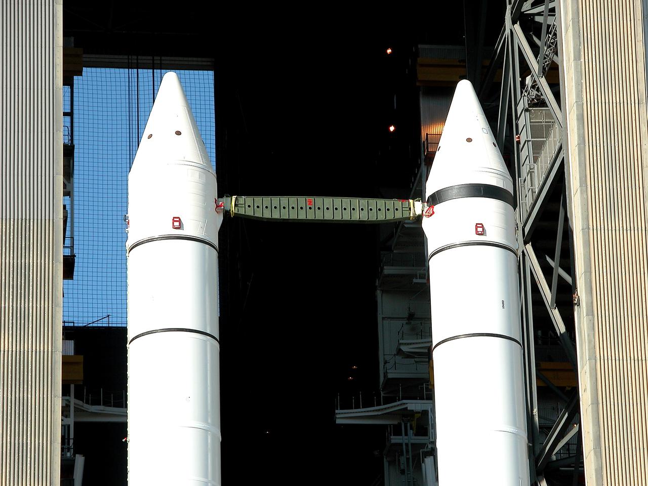
KENNEDY SPACE CENTER, FLA. - As the crawler transporter slowly moves the Mobile Launcher Platform (MLP) out of the Vehicle Assembly Building, the two solid rocket boosters on top are framed in the doorway. The move is in support of engineering analysis vibration tests on the crawler and MLP. The crawler is moving at various speeds up to 1 mph in an effort to achieve vibration data gathering goals as it leaves the VAB and then returns. The boosters are braced at the top for stability. The primary purpose of these rollout tests is to gather data to develop future maintenance requirements on the transport equipment and the flight hardware. Various parts of the MLP and crawler transporter have been instrumented with vibration data collection equipment.

KENNEDY SPACE CENTER, FLA. - The crawler transporter has slowly moved the Mobile Launcher Platform (MLP), carrying a set of twin solid rocket boosters, out of the Vehicle Assembly Building (VAB) in support of engineering analysis vibration tests on the crawler and MLP. The crawler is moving at various speeds up to 1 mph in an effort to achieve vibration data gathering goals as it leaves the VAB and then returns. The boosters are braced at the top for stability. The primary purpose of these rollout tests is to gather data to develop future maintenance requirements on the transport equipment and the flight hardware. Various parts of the MLP and crawler transporter have been instrumented with vibration data collection equipment.
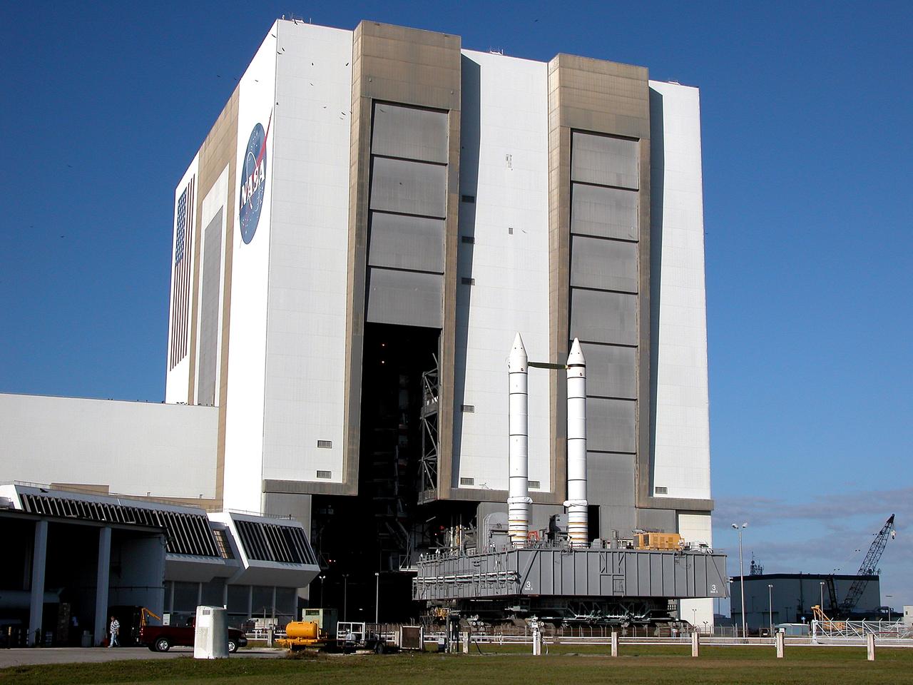
KENNEDY SPACE CENTER, FLA. - The crawler transporter slowly moves the Mobile Launcher Platform (MLP), carrying a set of twin solid rocket boosters, out of the Vehicle Assembly Building (VAB) in support of engineering analysis vibration tests on the crawler and MLP. The crawler is moving at various speeds up to 1 mph in an effort to achieve vibration data gathering goals as it leaves the VAB and then returns. The boosters are braced at the top for stability. The primary purpose of these rollout tests is to gather data to develop future maintenance requirements on the transport equipment and the flight hardware. Various parts of the MLP and crawler transporter have been instrumented with vibration data collection equipment.
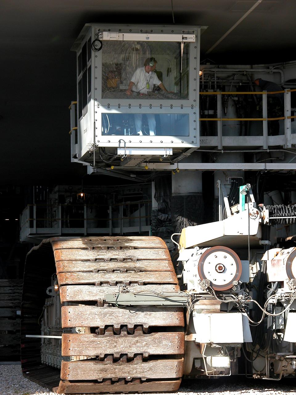
KENNEDY SPACE CENTER, FLA. - As the crawler transporter slowly moves the Mobile Launcher Platform (MLP) out of the Vehicle Assembly Building, the driver of the front control cab can be seen. The MLP is carrying two solid rocket boosters for engineering analysis vibration tests on the crawler and MLP. The crawler is moving at various speeds up to 1 mph in an effort to achieve vibration data gathering goals as it leaves the VAB and then returns. The boosters are braced at the top for stability. The primary purpose of these rollout tests is to gather data to develop future maintenance requirements on the transport equipment and the flight hardware. Various parts of the MLP and crawler transporter have been instrumented with vibration data collection equipment.
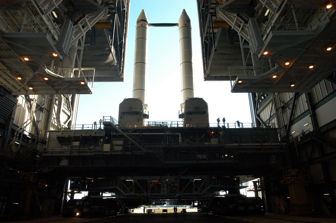
KENNEDY SPACE CENTER, FLA. - The crawler transporter is slowly moving the Mobile Launcher Platform (MLP), carrying a set of twin solid rocket boosters, out of the Vehicle Assembly Building (VAB) in support of engineering analysis vibration tests on the crawler and MLP. The crawler is moving at various speeds up to 1 mph in an effort to achieve vibration data gathering goals as it leaves the VAB and then returns. The boosters are braced at the top for stability. The primary purpose of these rollout tests is to gather data to develop future maintenance requirements on the transport equipment and the flight hardware. Various parts of the MLP and crawler transporter have been instrumented with vibration data collection equipment.

Photo shows how the Space Launch Sysetm (SLS) rocket liquid oxygen tank failed during a structural qualification test at NASA’s Marshall Space Flight Center in Huntsville, Alabama. The photos show both the water flowing from the tank as it ruptured and the resultant tear left in the tank when it buckled during the test. Engineers pushed the liquid oxygen structural test article to the limits on purpose. The tank is a test article that is identical to tanks that are part of the SLS core stage that will produce 2 million pounds of thrust to help launch the rocket on the Artemis missions to the Moon. During the test, hydraulic cylinders were then calibrated and positioned along the tank to apply millions of pounds of crippling force from all sides while engineers measured and recorded the effects of the launch and flight forces. For the test, water used to simulate the liquid oxygen flows out of the tank after it ruptures. The structural test campaign was conducted on the rocket to ensure the SLS rocket’s structure can endure the rigors of launch and safely send astronauts to the Moon on the Artemis missions. For more information: https://www.nasa.gov/exploration/systems/sls/nasa-completes-artemis-sls-structural-testing-campaign.html

Photo shows how the Space Launch Sysetm (SLS) rocket liquid oxygen tank failed during a structural qualification test at NASA’s Marshall Space Flight Center in Huntsville, Alabama. The photos show both the water flowing from the tank as it ruptured and the resultant tear left in the tank when it buckled during the test. Engineers pushed the liquid oxygen structural test article to the limits on purpose. The tank is a test article that is identical to tanks that are part of the SLS core stage that will produce 2 million pounds of thrust to help launch the rocket on the Artemis missions to the Moon. During the test, hydraulic cylinders were then calibrated and positioned along the tank to apply millions of pounds of crippling force from all sides while engineers measured and recorded the effects of the launch and flight forces. For the test, water used to simulate the liquid oxygen flows out of the tank after it ruptures. The structural test campaign was conducted on the rocket to ensure the SLS rocket’s structure can endure the rigors of launch and safely send astronauts to the Moon on the Artemis missions. For more information: https://www.nasa.gov/exploration/systems/sls/nasa-completes-artemis-sls-structural-testing-campaign.html

Photo shows how the Space Launch Sysetm (SLS) rocket liquid oxygen tank failed during a structural qualification test at NASA’s Marshall Space Flight Center in Huntsville, Alabama. The photos show both the water flowing from the tank as it ruptured and the resultant tear left in the tank when it buckled during the test. Engineers pushed the liquid oxygen structural test article to the limits on purpose. The tank is a test article that is identical to tanks that are part of the SLS core stage that will produce 2 million pounds of thrust to help launch the rocket on the Artemis missions to the Moon. During the test, hydraulic cylinders were then calibrated and positioned along the tank to apply millions of pounds of crippling force from all sides while engineers measured and recorded the effects of the launch and flight forces. For the test, water used to simulate the liquid oxygen flows out of the tank after it ruptures. The structural test campaign was conducted on the rocket to ensure the SLS rocket’s structure can endure the rigors of launch and safely send astronauts to the Moon on the Artemis missions. For more information: https://www.nasa.gov/exploration/systems/sls/nasa-completes-artemis-sls-structural-testing-campaign.html

Photo shows how the Space Launch Sysetm (SLS) rocket liquid oxygen tank failed during a structural qualification test at NASA’s Marshall Space Flight Center in Huntsville, Alabama. The photos show both the water flowing from the tank as it ruptured and the resultant tear left in the tank when it buckled during the test. Engineers pushed the liquid oxygen structural test article to the limits on purpose. The tank is a test article that is identical to tanks that are part of the SLS core stage that will produce 2 million pounds of thrust to help launch the rocket on the Artemis missions to the Moon. During the test, hydraulic cylinders were then calibrated and positioned along the tank to apply millions of pounds of crippling force from all sides while engineers measured and recorded the effects of the launch and flight forces. For the test, water used to simulate the liquid oxygen flows out of the tank after it ruptures. The structural test campaign was conducted on the rocket to ensure the SLS rocket’s structure can endure the rigors of launch and safely send astronauts to the Moon on the Artemis missions. For more information: https://www.nasa.gov/exploration/systems/sls/nasa-completes-artemis-sls-structural-testing-campaign.html
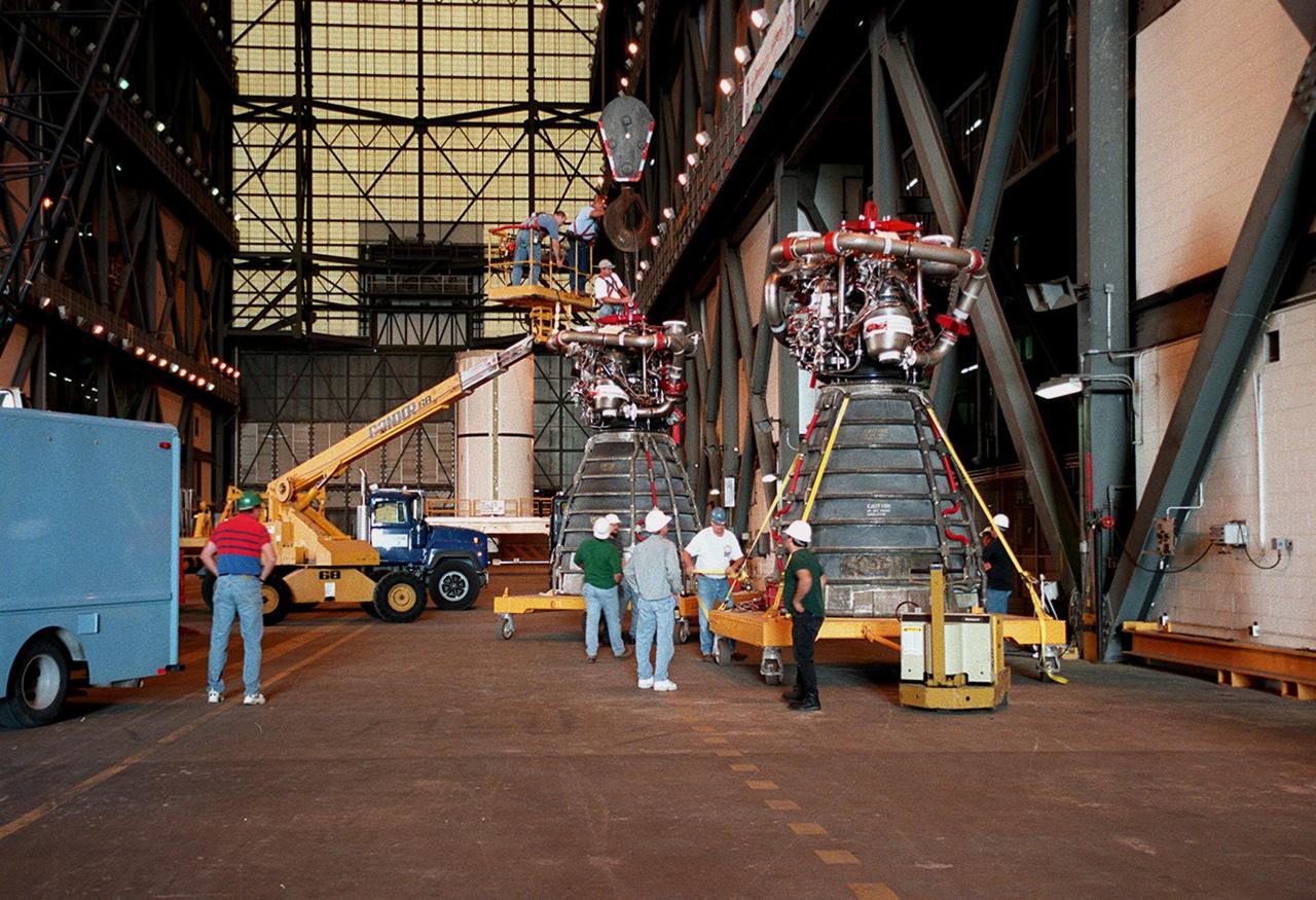
KENNEDY SPACE CENTER, FLA. -- Workers in the Vehicle Assembly Building move orbiter Endeavour's main engine No. 3 (in front) out of the way before moving the replacement engine into place. Following routine testing procedures on a separate test engine, analysis revealed delamination on the wall of the engine's main combustion chamber. When data revealed that one of Endeavour's engines had undergone similar testing procedures, managers opted to replace the suspect engine as a precaution. Space Shuttle Endeavour is targeted for launch on mission STS-99 on Jan. 13, 2000, at 1:11 p.m. EST. STS-99 is the Shuttle Radar Topography Mission
NASA engineers prepare for the test of the Orion spacecraft’s parachutes on Wednesday, Aug. 26 at the U.S. Army’s Yuma Proving Ground in Arizona on Aug. 24, 2015. An engineering model of the spacecraft will drop from an airplane 35,000 feet up to evaluate how it fares when the parachute system does not perform as expected...During the test, Orion engineers will carry out a scenario in which one of the spacecraft’s two drogue parachutes and one of its three main parachutes fail. This high-risk assessment is the penultimate drop test of the scheduled engineering evaluations leading up to next year’s tests to qualify the parachute system for crewed flights. Part of Batch image transfer from Flickr.
The new production nozzle is lifted on the Fred Haise Test Stand at NASA’s Stennis Space Center on Feb. 6. Crews used specially adapted procedures and tools to swap out the nozzles with the engine in place.
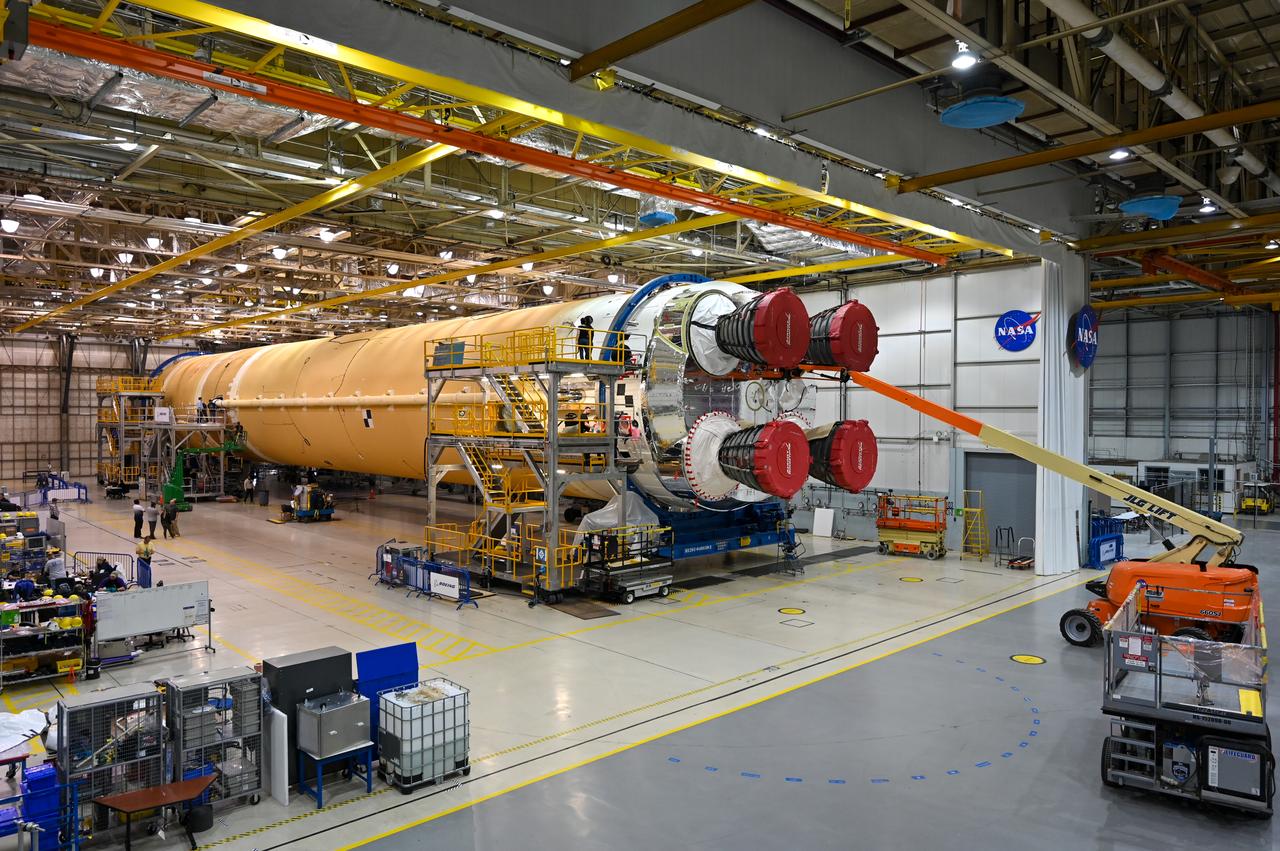
This image shows the core stage for NASA’s Space Launch System (SLS) rocket without scaffolding at NASA’s Michoud Assembly Facility in New Orleans. Assembly and integration of the core stage and its four RS-25 engines has been a collaborative, multistep process for NASA and its partners Boeing, the core stage lead contractor, and Aerojet Rocketdyne, the RS-25 engines lead contractor. NASA and the contractor team used the scaffolding previously positioned around the 212-foot core stage to assess the stage’s inside and check out the electronic systems distributed throughout the stage, including avionics and propulsion systems, that will enable the stage to operate during launch and flight. The team will continue to check out these systems at NASA’s Stennis Space Center near Bay St. Louis, Mississippi, where it will undergo the core stage Green Run testing.

A team of engineers from NASA's John C. Stennis Space Center, Orbital Sciences Corporation and Aerojet conduct a successful test of an Aerojet AJ26 rocket engine on March 19. Stennis is testing AJ26 engines for Orbital Sciences to power commercial cargo missions to the International Space Station. Orbital has partnered with NASA through the Commercial Orbital Transportation Services initiative to carry out eight cargo missions to the space station by 2015, using Taurus II rockets.
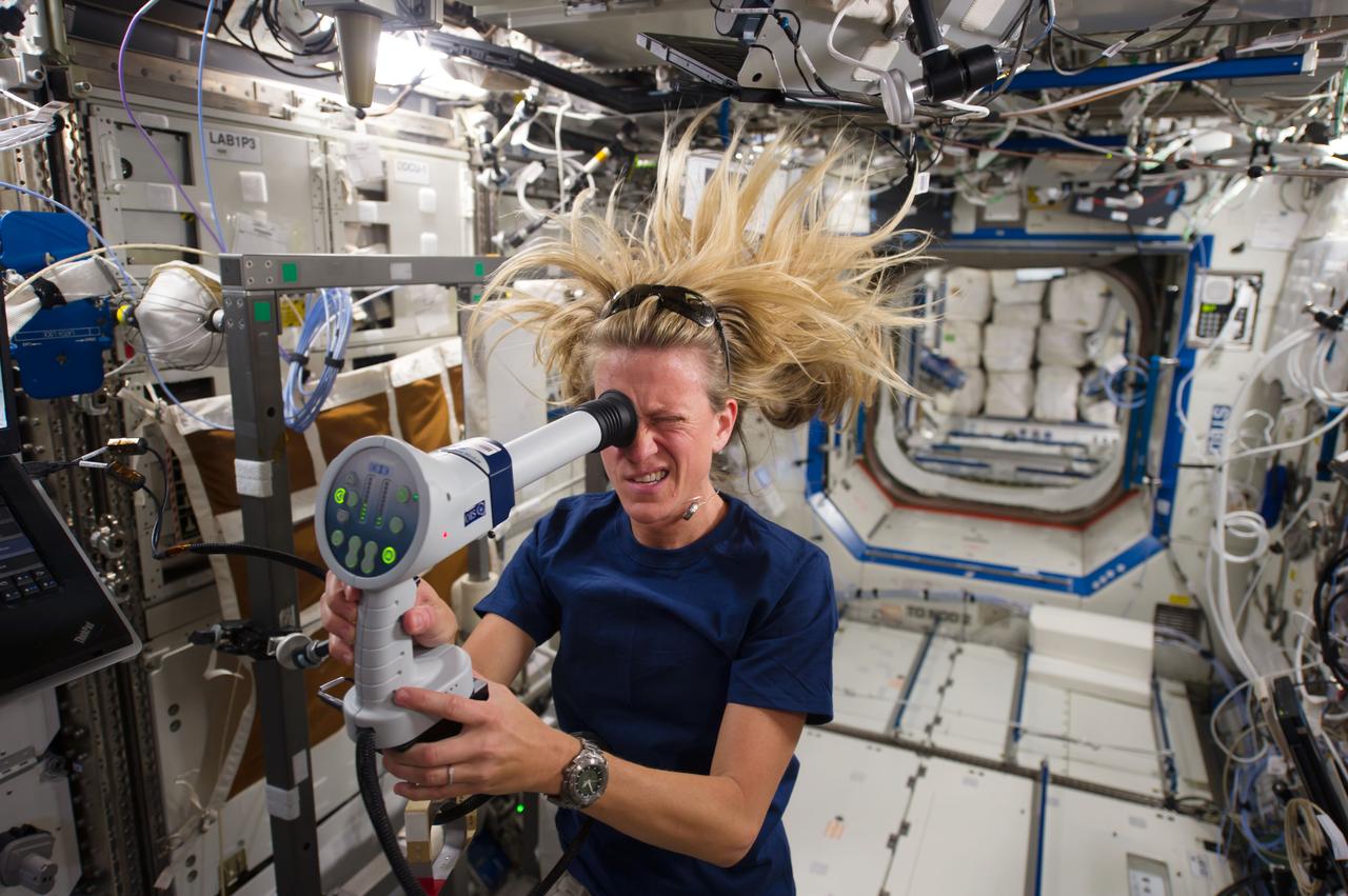
ISS036-E-006520 (5 June 2013) --- NASA astronaut Karen Nyberg, Expedition 36 flight engineer, conducts an ocular health exam on herself in the Destiny laboratory of the Earth-orbiting International Space Station. NASA astronaut Chris Cassidy, flight engineer, nearby but out of frame, assisted in the testing, part of a suite of eye exams carried out over a two-day period on various crew members to gather information on intraocular pressure and eye anatomy.
Pictured is one of the earliest testing of the Saturn I S-I (first) stage, with a cluster of eight H-1 engines, at the Marshall Space Flight Center (MSFC). It was a part of the test program to prove out the clustered-booster concept. MSFC was responsible for designing and development the Saturn launch vehicles.

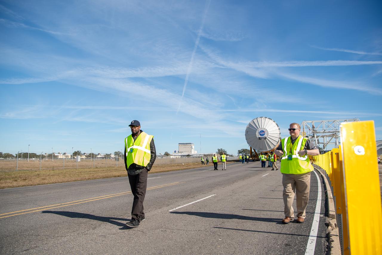
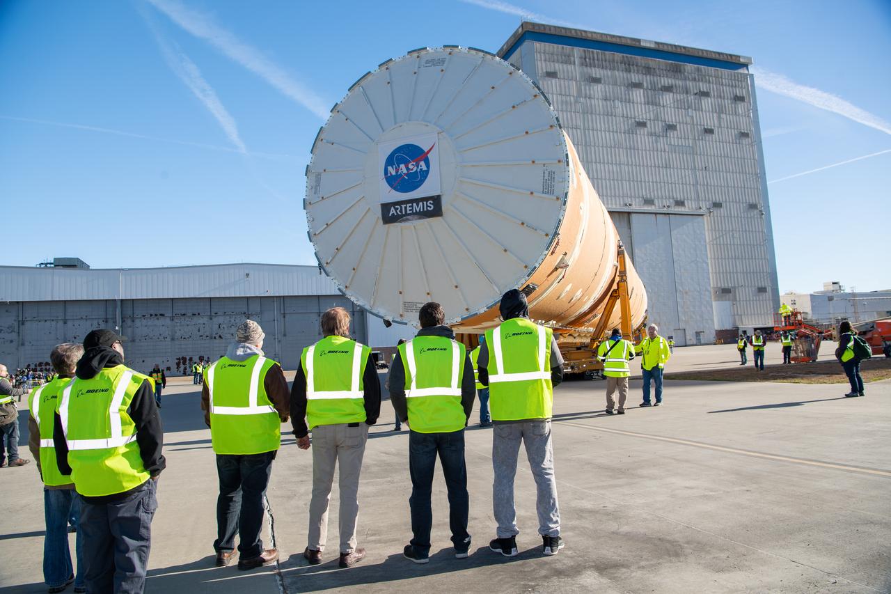
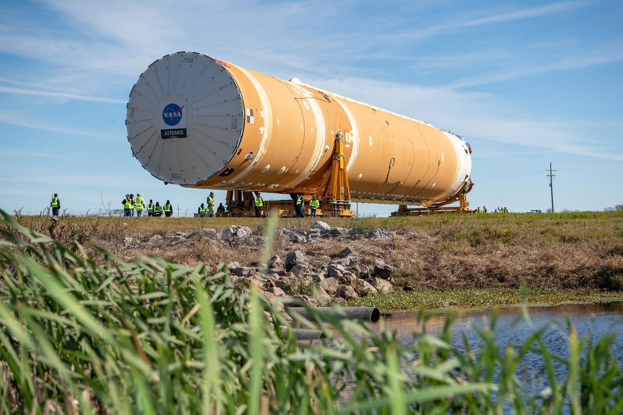
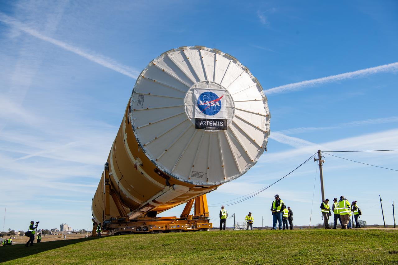
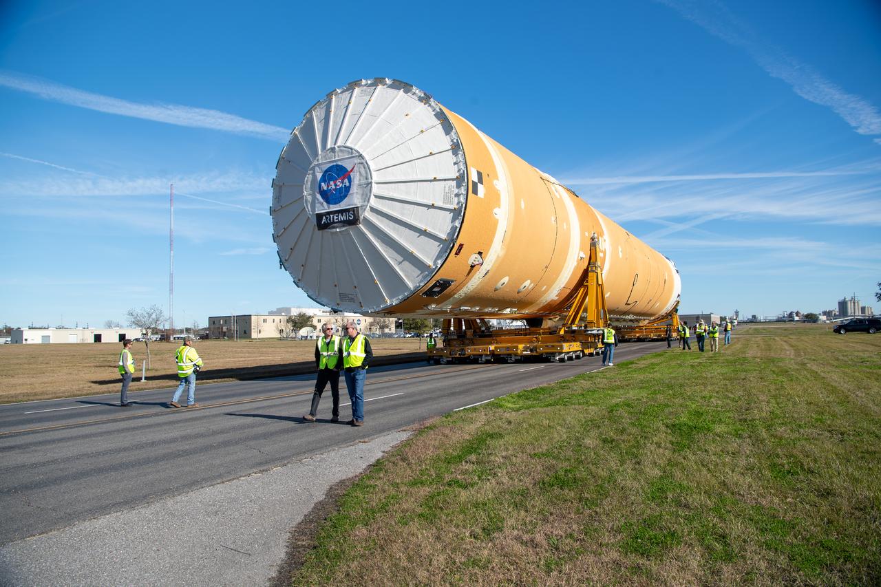
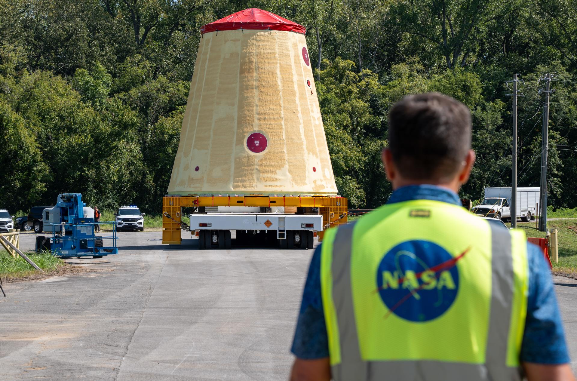
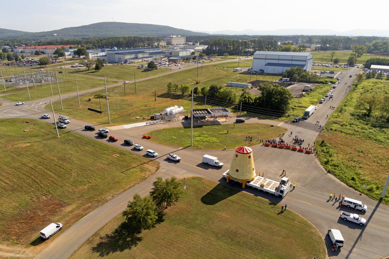
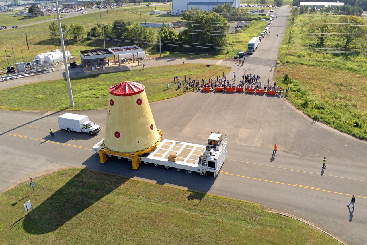
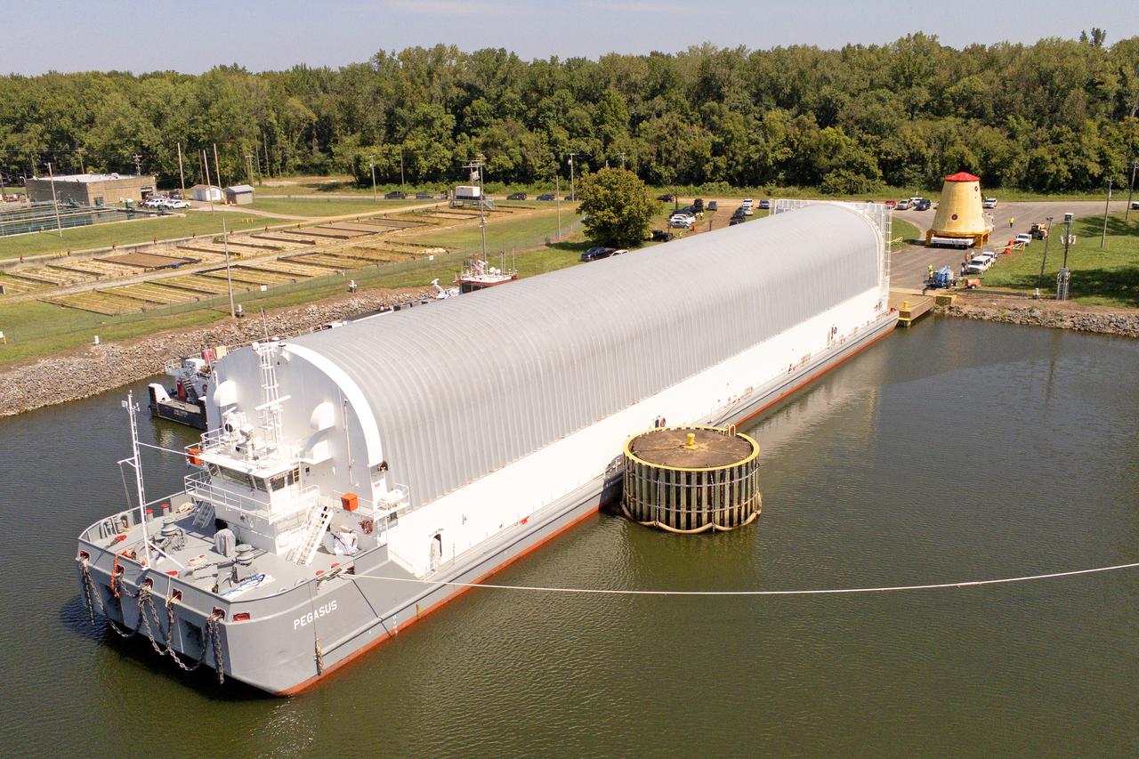
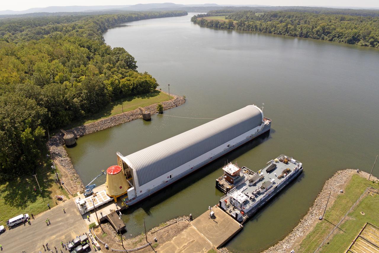
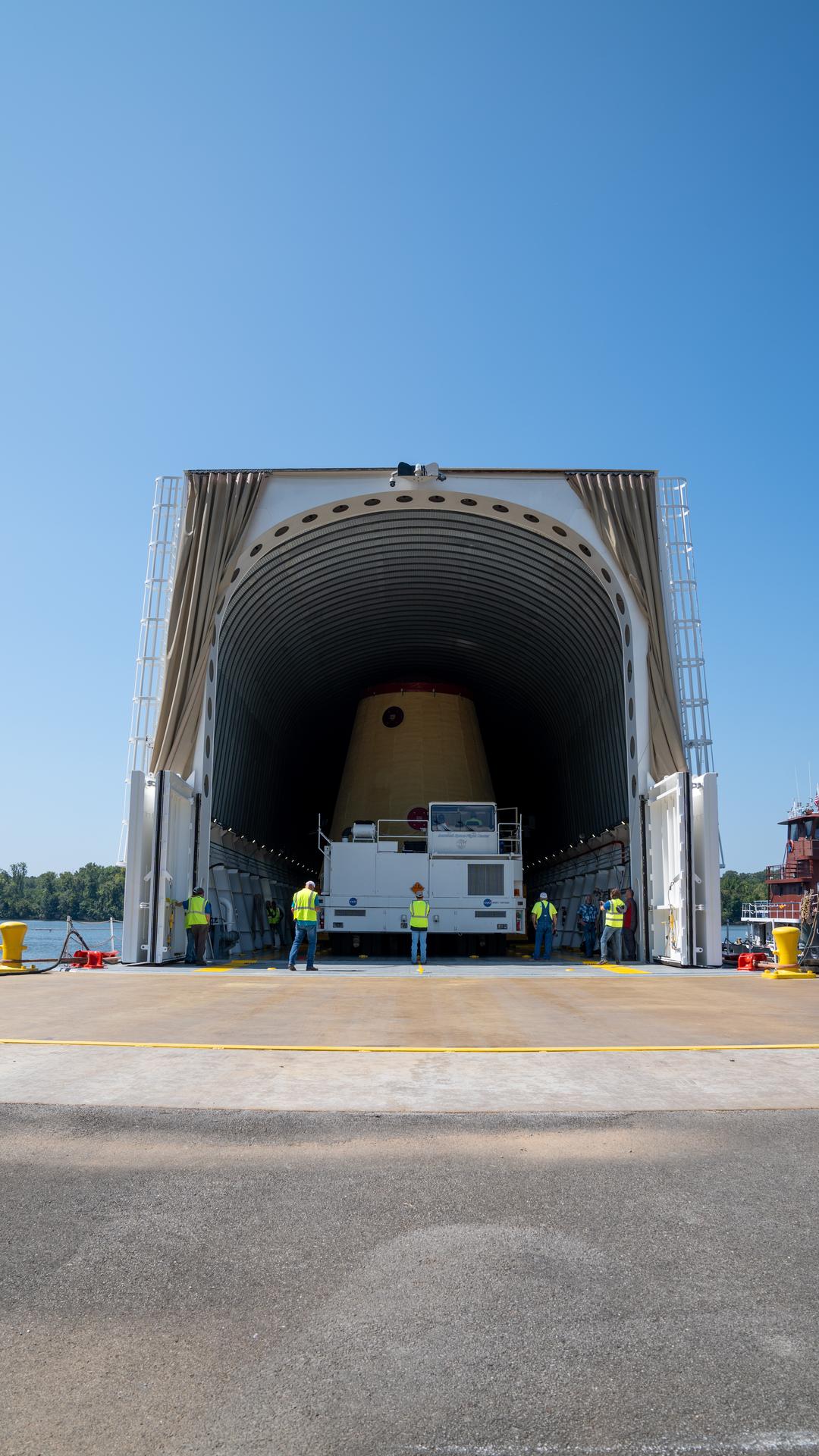
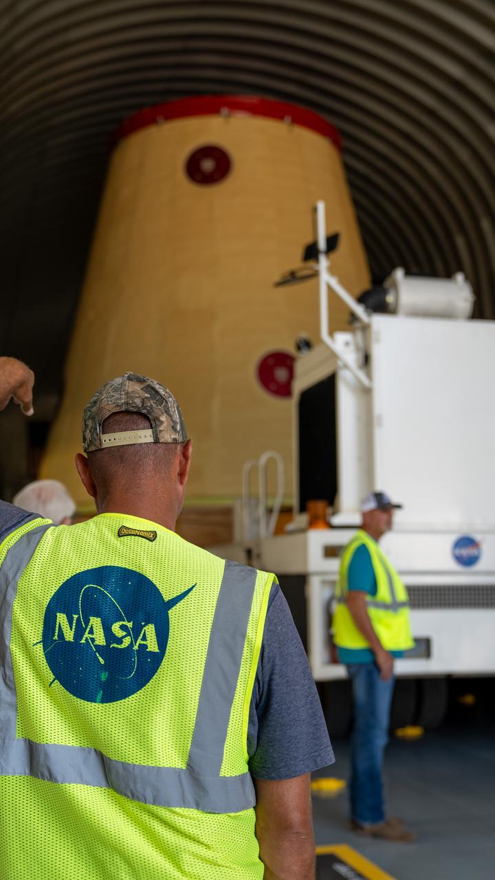
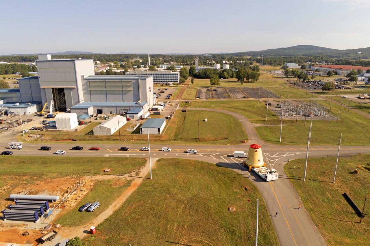
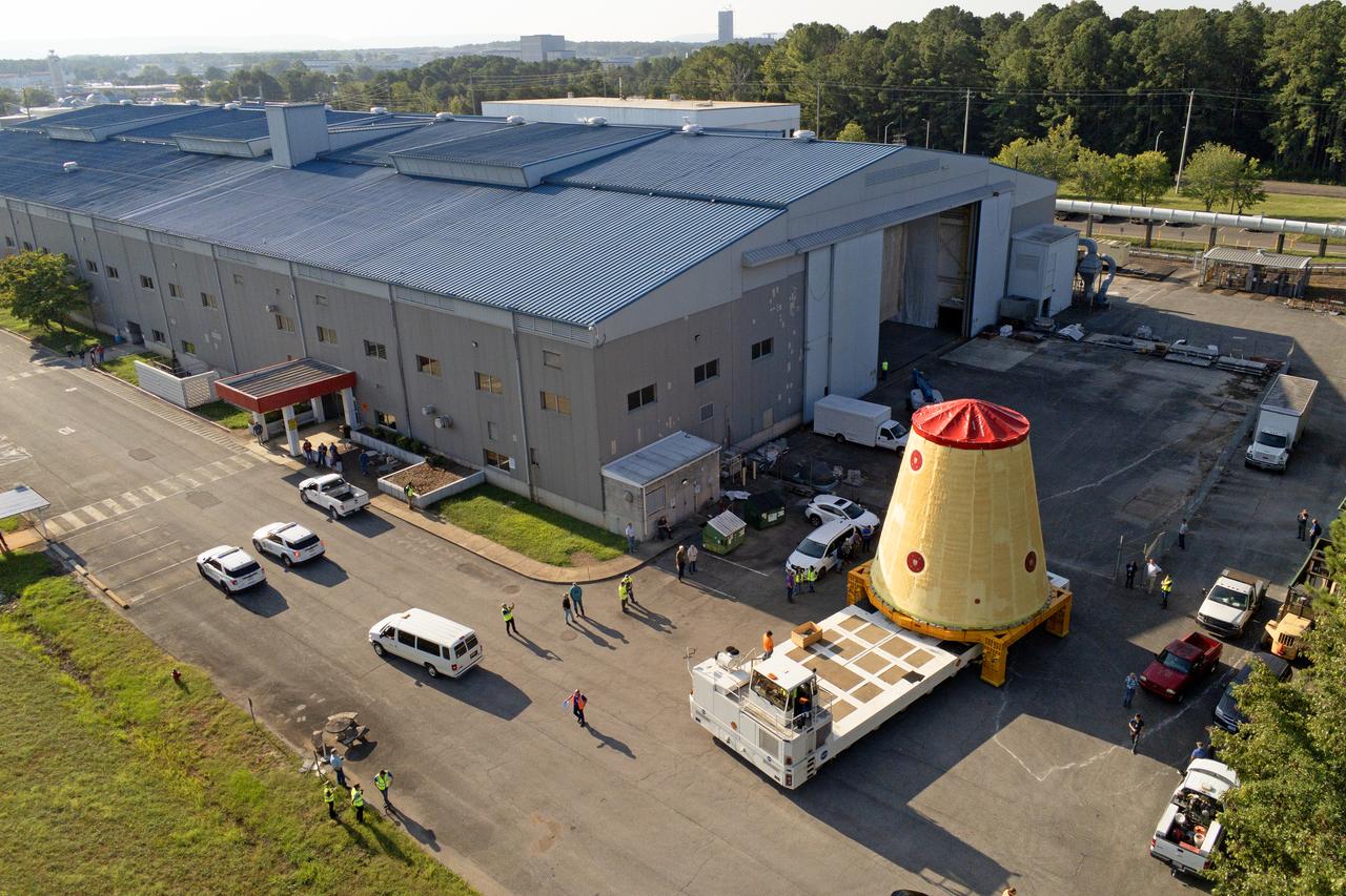
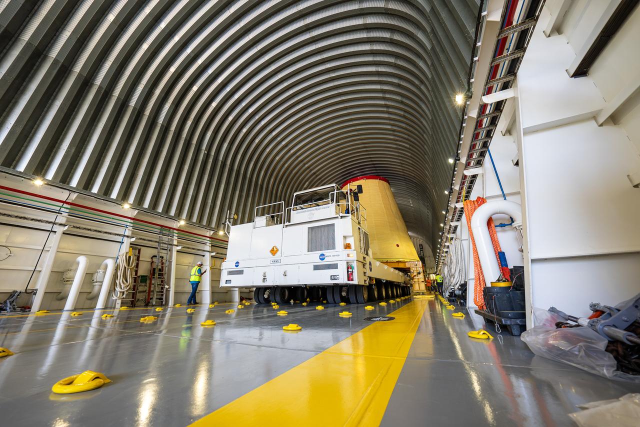
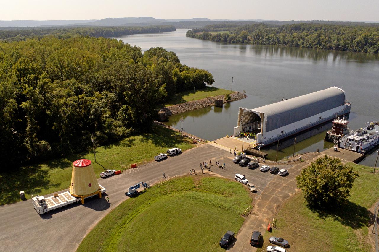
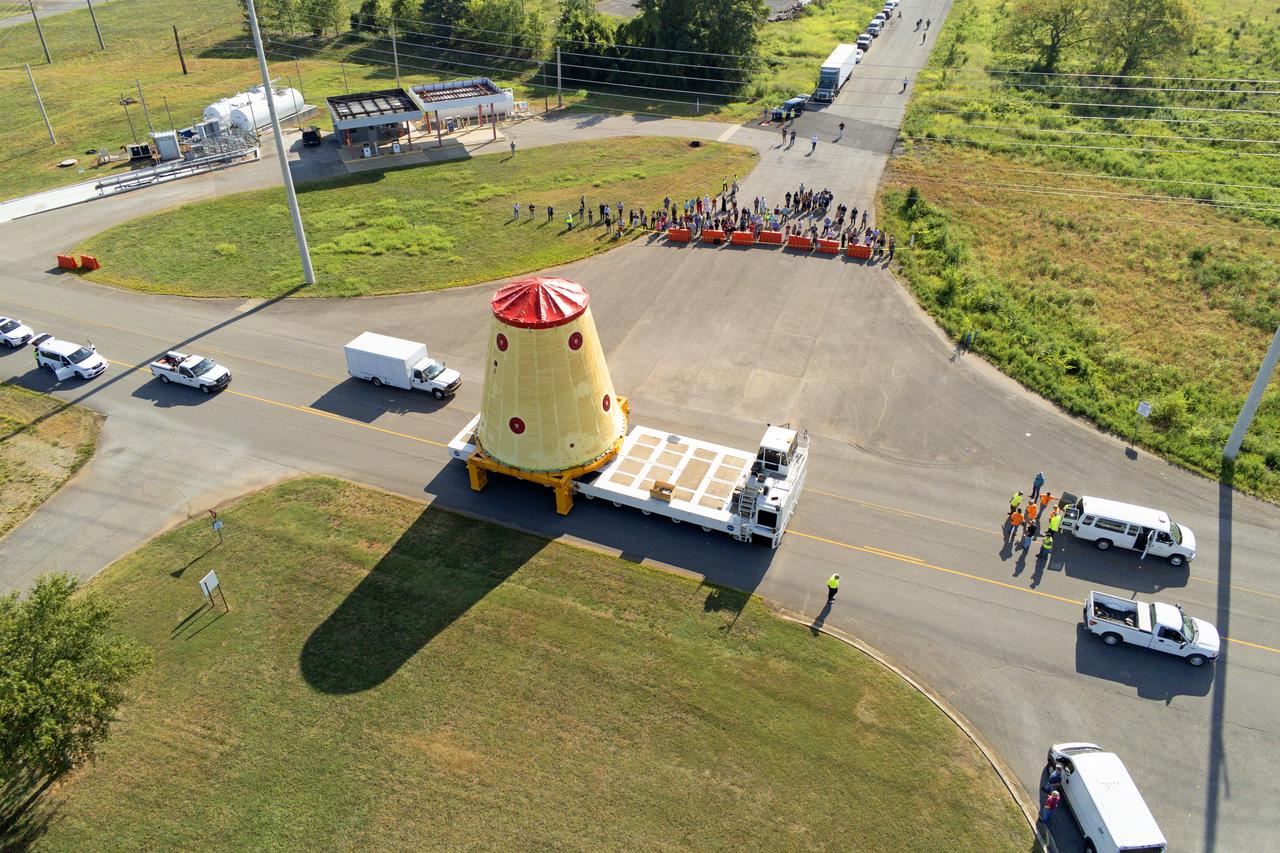
NASA rolled out a key piece of space flight hardware for the SLS (Space Launch System) rocket for the first crewed mission of NASA’s Artemis campaign from Marshall Space Flight Center in Huntsville, Alabama, on Wednesday, Aug. 21 to board the Pegasus barge for shipment to the agency’s spaceport in Florida. The cone-shaped launch vehicle stage adapter connects the rocket’s core stage to the upper stage and helps protect the upper stage’s engine that will help propel the Artemis II test flight around the Moon, slated for 2026.
iss069e005093 (April 24, 2023) --- NASA astronaut and Expedition 69 Flight Engineer Stephen Bowen is pictured trying on his Extravehicular Mobility Unit, or spacesuit, and testing it ahead of a spacewalk planned for Friday, April 28. Bowen, along with UAE (United Arab Emirates) astronaut Sultan Alneyadi, will spend about six-and-a-half hours in the vacuum of space continuing to upgrade the International Space Station’s power generation system readying the orbiting lab for its next set of roll-out solar arrays.
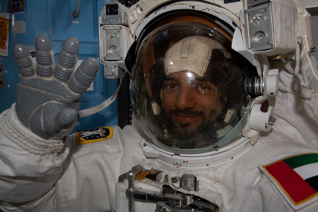
iss069e005102 (April 24, 2023) --- UAE (United Arab Emirates) astronaut and Expedition 69 Flight Engineer Sultan Alneyadi is pictured trying on his Extravehicular Mobility Unit, or spacesuit, and testing it ahead of a spacewalk planned for Friday, April 28. Alneyadi, along with NASA astronaut Stephen Bowen, will spend about six-and-a-half hours in the vacuum of space continuing to upgrade the International Space Station’s power generation system readying the orbiting lab for its next set of roll-out solar arrays.
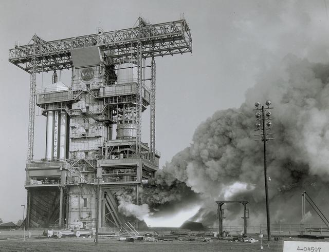
The flame and exhaust from the test firing of an F-1 engine blast out from the Saturn S-IB Static Test Stand in the east test area of the Marshall Space Flight Center. A Cluster of five F-1 engines, located in the S-IC (first) stage of the Saturn V vehicle, provided over 7,500,000 pounds of thrust to launch the giant rocket. The towering 363-foot Saturn V was a multistage, multiengine launch vehicle standing taller than the Statue of Liberty. Altogether, the Saturn V engines produced as much power as 85 Hoover Dams.
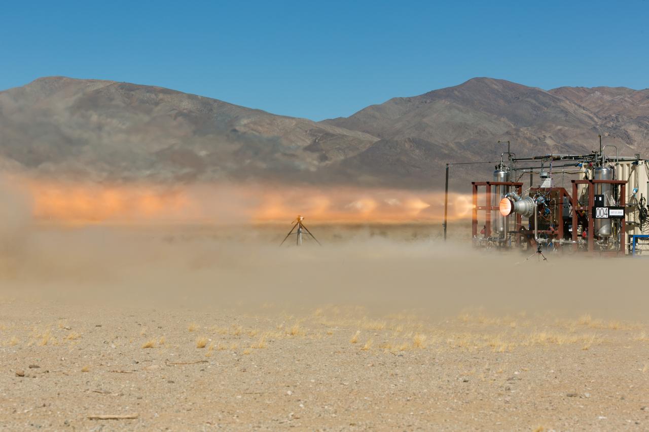
A launch abort engine built by Aerojet Rocketdyne is hot-fired during tests in the Mojave Desert in California. The engine produces up to 40,000 pounds of thrust and burns hypergolic propellants. The engines have been designed and built for use on Boeing’s CST-100 Starliner spacecraft in sets of four. In an emergency at the pad or during ascent, the engines would ignite to push the Starliner and its crew out of danger.
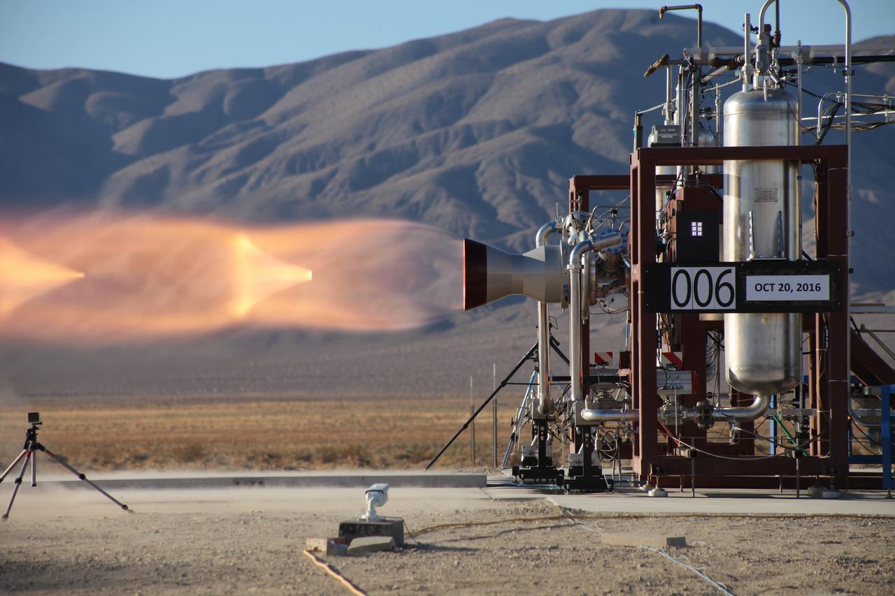
A launch abort engine built by Aerojet Rocketdyne is hot-fired during tests in the Mojave Desert in California. The engine produces up to 40,000 pounds of thrust and burns hypergolic propellants. The engines have been designed and built for use on Boeing’s CST-100 Starliner spacecraft in sets of four. In an emergency at the pad or during ascent, the engines would ignite to push the Starliner and its crew out of danger.
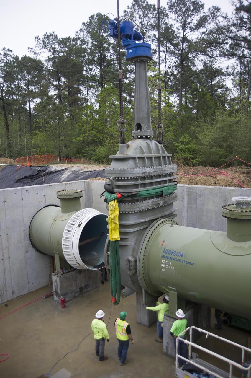
Stennis Space Center employees install a 96-inch valve during a recent upgrade of the high-pressure industrial water system that serves the site’s large rocket engine test stands. The upgraded system has a capacity to flow 335,000 gallons of water a minute, which is a critical element for testing. At Stennis, engines are anchored in place on large test stands and fired just as they are during an actual space flight. The fire and exhaust from the test is redirected out of the stand by a large flame trench. A water deluge system directs thousands of gallons of water needed to cool the exhaust. Water also must be available for fire suppression in the event of a mishap. The new system supports RS-25 engine testing on the A-1 Test Stand, as well as testing of the core stage of NASA’s new Space Launch System on the B-2 Test Stand at Stennis.
Performance Acceptance Test of a prototype-model NEXT (NASA Evolutionary Xenon Thruster) ion engine that was delivered to NASA Glenn Research Center by Aerojet. The test dates were May 10 - May 17, 2006. The test was conducted in the Vacuum Facility 6 test facility located in the Electric Power Laboratory. The test successfully demonstrated the PM manufacturing process carried out by Aerojet under the guidance of NASA Glenn Research Center and PM1 acceptable functionality
NASA Administrator Charles Bolden (l) and John C. Stennis Space Center Director Patrick Scheuermann watch the successful test of the first Aerojet AJ26 flight engine Feb. 7, 2011. The test was conducted on the E-1 Test Stand at Stennis. The engine now will be sent to Wallops Flight Facility in Virginia, where it will be used to power the first stage of Orbital Sciences Corporation's Taurus II space vehicle. The Feb. 7 test supports NASA's commitment to partner with companies to provide commercial cargo flights to the International Space Station. NASA has partnered with Orbital to carry out the first of eight cargo missions to the space station in early 2012.
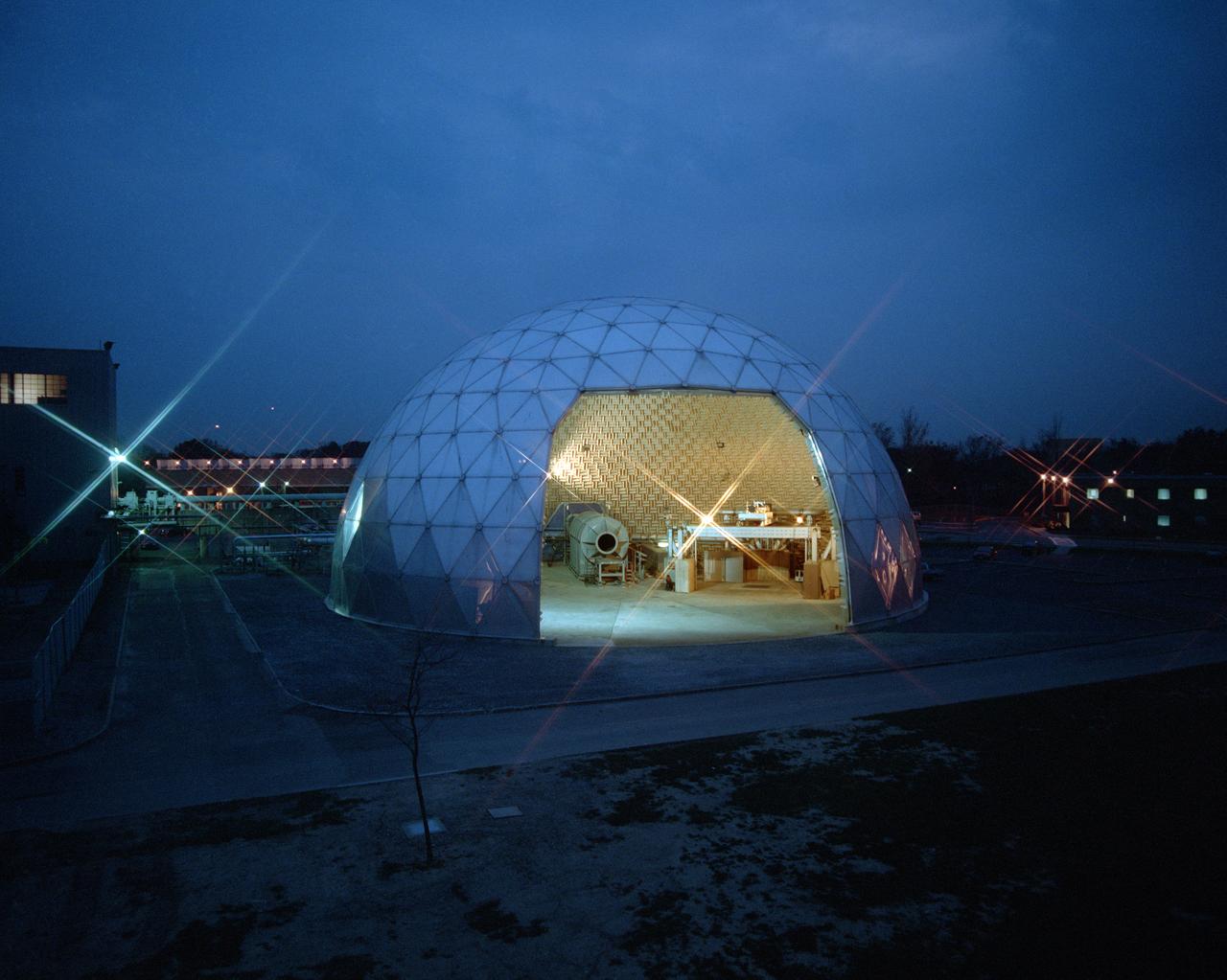
Modern jet engines are loud, but they used to be much louder. NASA’s Glenn Research Center has been at the forefront of the nation’s efforts to reduce aircraft engine noise for over 70 years. During this time, the center has built an array of test facilities to carry out this work, culminating in the Aero-Acoustic Propulsion Laboratory (AAPL), a world-class noise-reduction research facility. The AAPL, referred to as “the dome,” contains multiple test rigs enclosed in a large, echo-free chamber. The unique 130-foot diameter and 65-foot-high hemispherical structure stands out on Glenn’s campus. Its triangular sections make it appear like a golf ball rising from the ground. The interior is covered in spiky, fiberglass sound-dampening wedges and an overhead array of microphones that capture engine noise data.
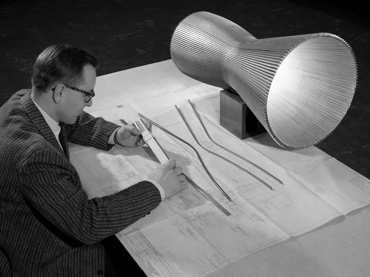
An engineer at the National Aeronautics and Space Administration (NASA) Lewis Research Center examines a drawing showing the assembly and details of a 20,000-pound thrust regeneratively cooled rocket engine. The engine was being designed for testing in Lewis’ new Rocket Engine Test Facility, which began operating in the fall of 1957. The facility was the largest high-energy test facility in the country that was capable of handling liquid hydrogen and other liquid chemical fuels. The facility’s use of subscale engines up to 20,000 pounds of thrust permitted a cost-effective method of testing engines under various conditions. The Rocket Engine Test Facility was critical to the development of the technology that led to the use of hydrogen as a rocket fuel and the development of lightweight, regeneratively-cooled, hydrogen-fueled rocket engines. Regeneratively-cooled engines use the cryogenic liquid hydrogen as both the propellant and the coolant to prevent the engine from burning up. The fuel was fed through rows of narrow tubes that surrounded the combustion chamber and nozzle before being ignited inside the combustion chamber. The tubes are visible in the liner sitting on the desk. At the time, Pratt and Whitney was designing a 20,000-pound thrust liquid-hydrogen rocket engine, the RL-10. Two RL-10s would be used to power the Centaur second-stage rocket in the 1960s. The successful development of the Centaur rocket and the upper stages of the Saturn V were largely credited to the work carried out Lewis.
The Saturn project was approved on January 18, 1960 as a program of the highest national priority. The formal test program to prove out the clustered-booster concept was well underway. A series of static tests of the Saturn I booster (S-I stage) began June 3, 1960 at the Marshall Space Flight Center (MSFC). This photograph depicts the Saturn I S-I stage equipped with eight H-1 engines, being successfully test-fired on February 4, 1961. A Juno rocket is visible on the right side of the test stand.
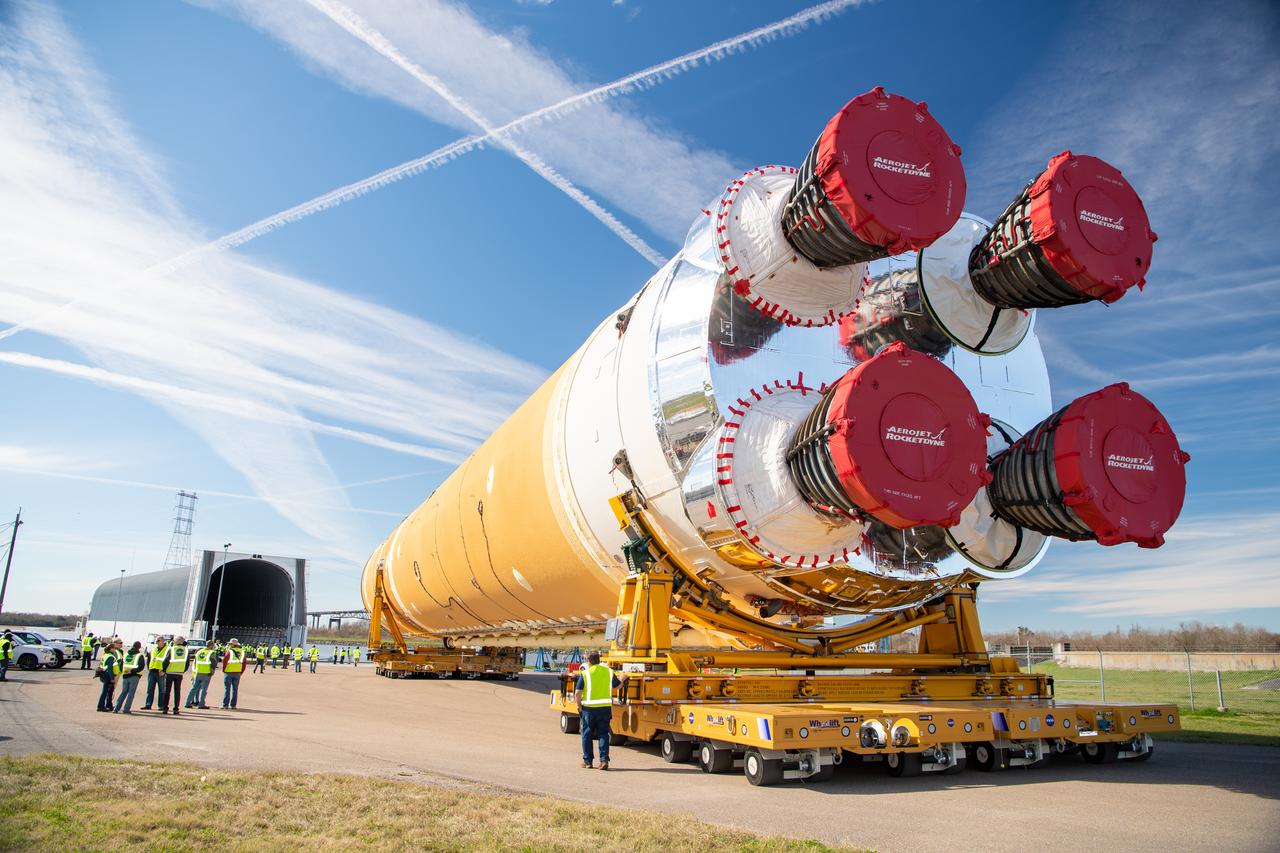
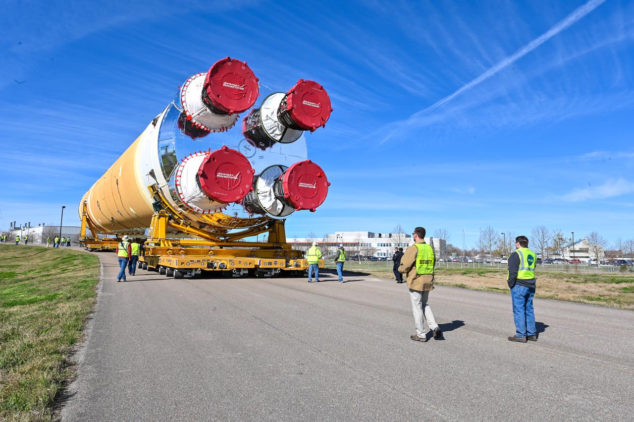
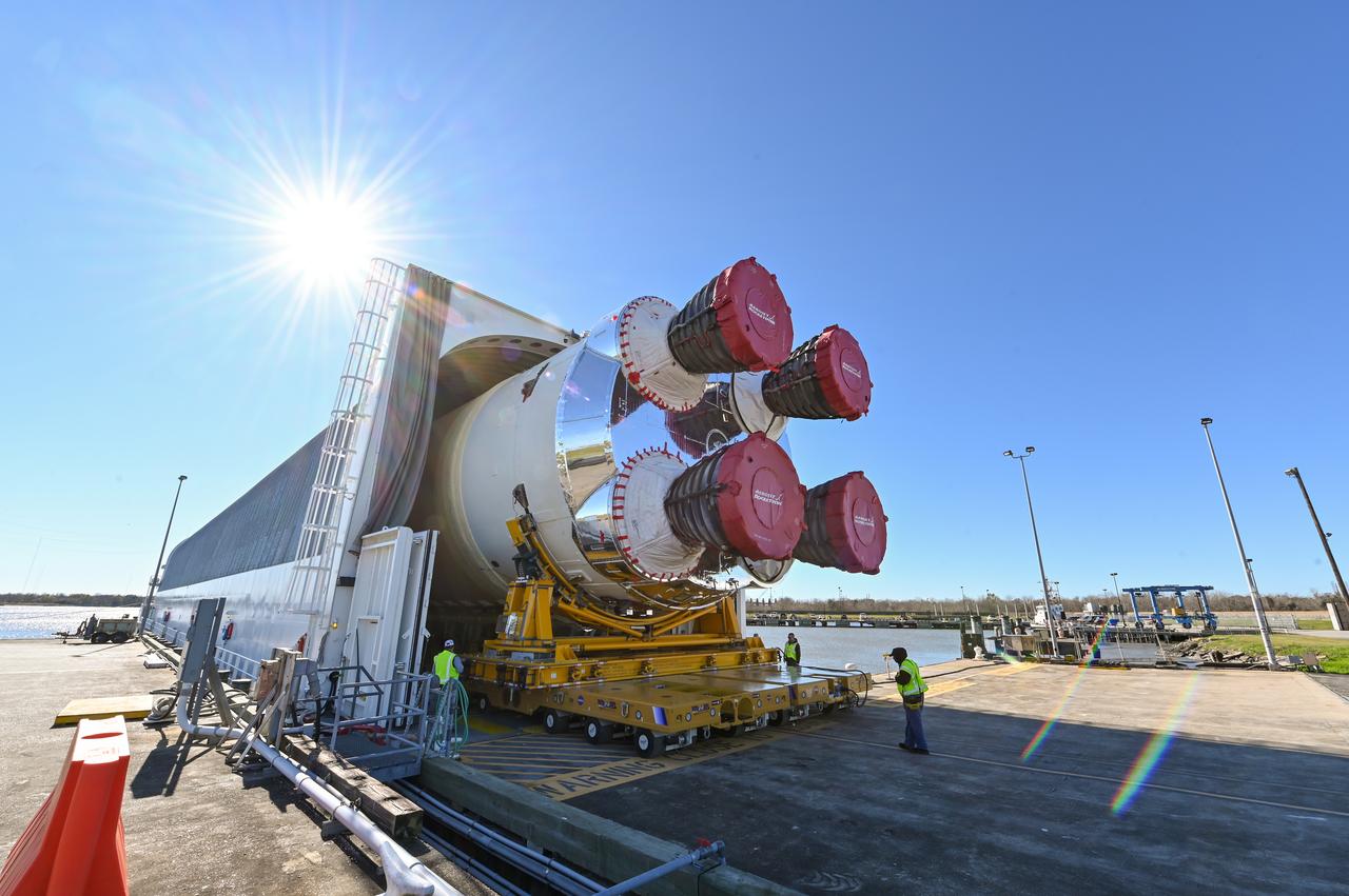
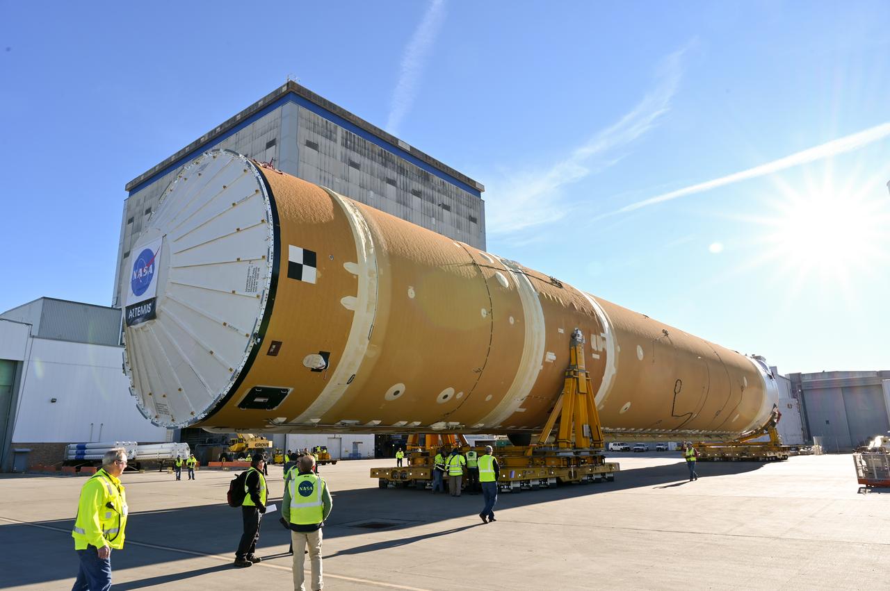
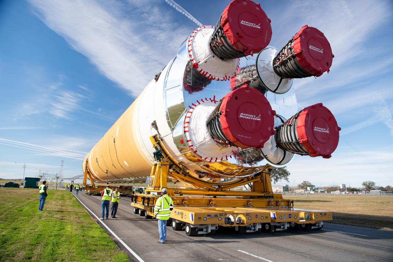
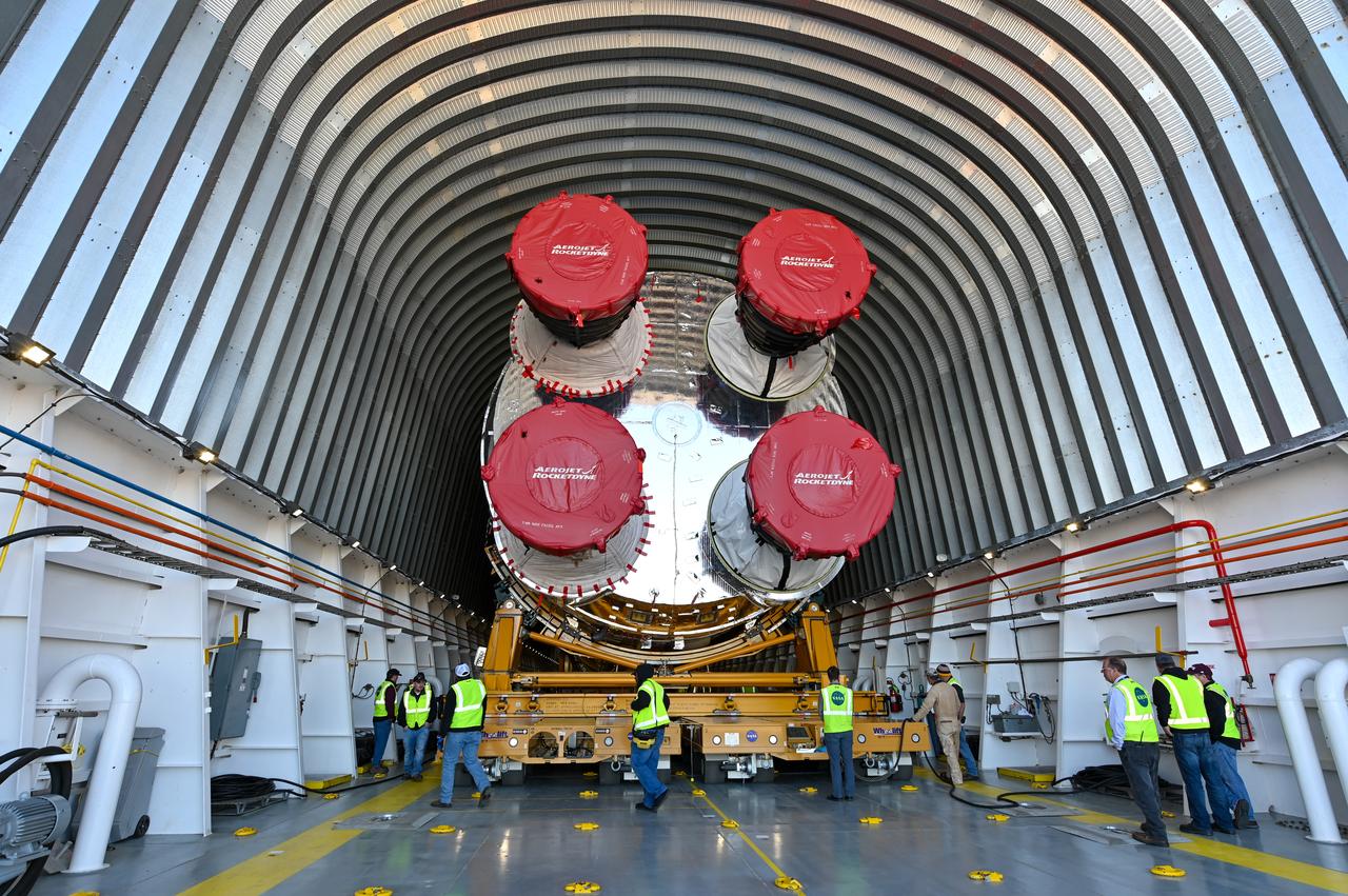
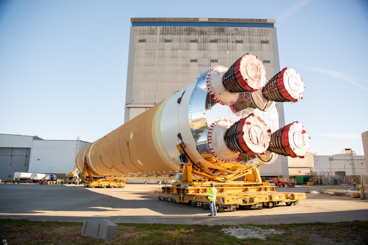
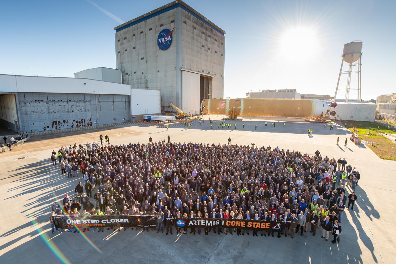
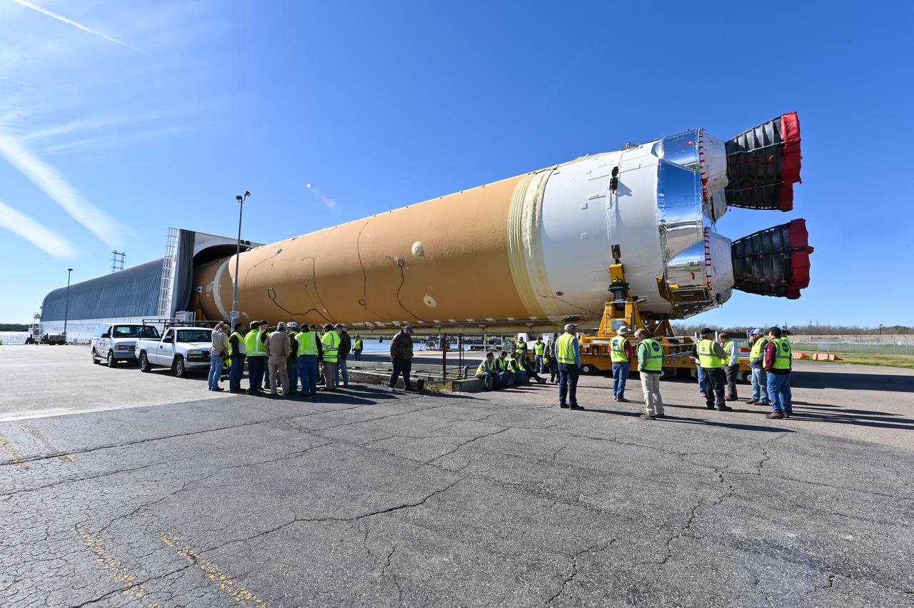
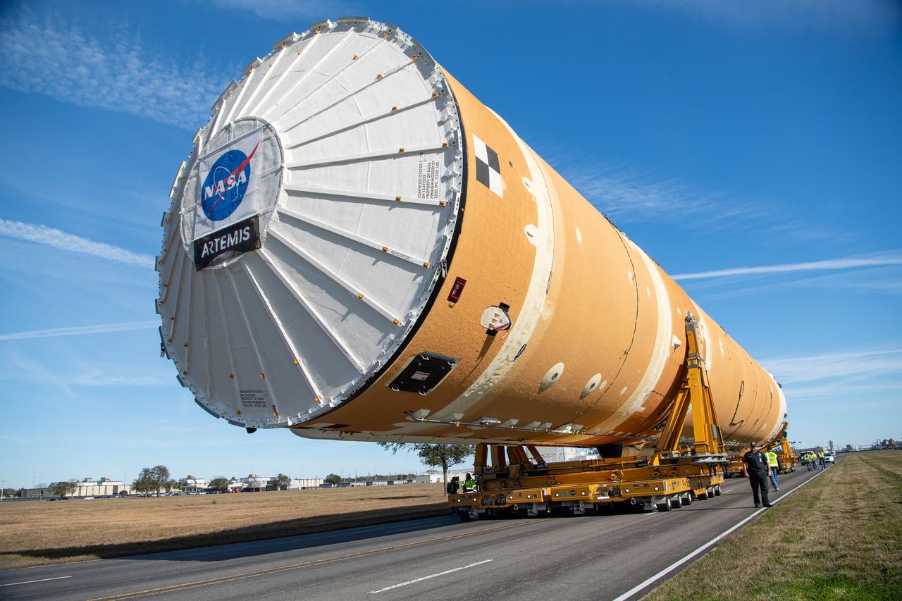
These images show how teams rolled out, or moved, the completed core stage for NASA’s Space Launch System rocket from NASA’s Michoud Assembly Facility in New Orleans. Crews moved the flight hardware for the first Artemis mission to NASA’s Pegasus barge on Jan. 8 in preparation for the core stage Green Run test series at NASA’s Stennis Space Center near Bay St. Louis, Mississippi. Pegasus, which was modified to ferry SLS rocket hardware, will transport the core stage from Michoud to Stennis for the comprehensive core stage Green Run test series. Once at Stennis, the Artemis rocket stage will be loaded into the B-2 Test Stand for the core stage Green Run test series. The comprehensive test campaign will progressively bring the entire core stage, including its avionics and engines, to life for the first time to verify the stage is fit for flight ahead of the launch of Artemis I. Assembly and integration of the core stage and its four RS-25 engines has been a collaborative, multistep process for NASA and its partners Boeing, the core stage lead contractor, and Aerojet Rocketdyne, the RS-25 engines lead contractor. Together with four RS-25 engines, the rocket’s massive 212-foot-tall core stage — the largest stage NASA has ever built — and its twin solid rocket boosters will produce 8.8 million pounds of thrust to send NASA’s Orion spacecraft, astronauts and supplies beyond Earth’s orbit to the Moon and, ultimately, Mars. Offering more payload mass, volume capability and energy to speed missions through space, the SLS rocket, along with NASA’s Gateway in lunar orbit and Orion, is part of NASA’s backbone for deep space exploration and the Artemis lunar program.
These images/video show how teams rolled out, or moved, the completed core stage for NASA’s Space Launch System rocket from NASA’s Michoud Assembly Facility in New Orleans. Crews moved the flight hardware for the first Artemis mission to NASA’s Pegasus barge on Jan. 8 in preparation for the core stage Green Run test series at NASA’s Stennis Space Center near Bay St. Louis, Mississippi. Pegasus, which was modified to ferry SLS rocket hardware, will transport the core stage from Michoud to Stennis for the comprehensive core stage Green Run test series. Once at Stennis, the Artemis rocket stage will be loaded into the B-2 Test Stand for the core stage Green Run test series. The comprehensive test campaign will progressively bring the entire core stage, including its avionics and engines, to life for the first time to verify the stage is fit for flight ahead of the launch of Artemis I. Assembly and integration of the core stage and its four RS-25 engines has been a collaborative, multistep process for NASA and its partners Boeing, the core stage lead contractor, and Aerojet Rocketdyne, the RS-25 engines lead contractor. Together with four RS-25 engines, the rocket’s massive 212-foot-tall core stage — the largest stage NASA has ever built — and its twin solid rocket boosters will produce 8.8 million pounds of thrust to send NASA’s Orion spacecraft, astronauts and supplies beyond Earth’s orbit to the Moon and, ultimately, Mars. Offering more payload mass, volume capability and energy to speed missions through space, the SLS rocket, along with NASA’s Gateway in lunar orbit and Orion, is part of NASA’s backbone for deep space exploration and the Artemis lunar program.
These images show how teams rolled out, or moved, the completed core stage for NASA’s Space Launch System rocket from NASA’s Michoud Assembly Facility in New Orleans. Crews moved the flight hardware for the first Artemis mission to NASA’s Pegasus barge on Jan. 8 in preparation for the core stage Green Run test series at NASA’s Stennis Space Center near Bay St. Louis, Mississippi. Pegasus, which was modified to ferry SLS rocket hardware, will transport the core stage from Michoud to Stennis for the comprehensive core stage Green Run test series. Once at Stennis, the Artemis rocket stage will be loaded into the B-2 Test Stand for the core stage Green Run test series. The comprehensive test campaign will progressively bring the entire core stage, including its avionics and engines, to life for the first time to verify the stage is fit for flight ahead of the launch of Artemis I. Assembly and integration of the core stage and its four RS-25 engines has been a collaborative, multistep process for NASA and its partners Boeing, the core stage lead contractor, and Aerojet Rocketdyne, the RS-25 engines lead contractor. Together with four RS-25 engines, the rocket’s massive 212-foot-tall core stage — the largest stage NASA has ever built — and its twin solid rocket boosters will produce 8.8 million pounds of thrust to send NASA’s Orion spacecraft, astronauts and supplies beyond Earth’s orbit to the Moon and, ultimately, Mars. Offering more payload mass, volume capability and energy to speed missions through space, the SLS rocket, along with NASA’s Gateway in lunar orbit and Orion, is part of NASA’s backbone for deep space exploration and the Artemis lunar program.
These images show how teams rolled out, or moved, the completed core stage for NASA’s Space Launch System rocket from NASA’s Michoud Assembly Facility in New Orleans. Crews moved the flight hardware for the first Artemis mission to NASA’s Pegasus barge on Jan. 8 in preparation for the core stage Green Run test series at NASA’s Stennis Space Center near Bay St. Louis, Mississippi. Pegasus, which was modified to ferry SLS rocket hardware, will transport the core stage from Michoud to Stennis for the comprehensive core stage Green Run test series. Once at Stennis, the Artemis rocket stage will be loaded into the B-2 Test Stand for the core stage Green Run test series. The comprehensive test campaign will progressively bring the entire core stage, including its avionics and engines, to life for the first time to verify the stage is fit for flight ahead of the launch of Artemis I. Assembly and integration of the core stage and its four RS-25 engines has been a collaborative, multistep process for NASA and its partners Boeing, the core stage lead contractor, and Aerojet Rocketdyne, the RS-25 engines lead contractor. Together with four RS-25 engines, the rocket’s massive 212-foot-tall core stage — the largest stage NASA has ever built — and its twin solid rocket boosters will produce 8.8 million pounds of thrust to send NASA’s Orion spacecraft, astronauts and supplies beyond Earth’s orbit to the Moon and, ultimately, Mars. Offering more payload mass, volume capability and energy to speed missions through space, the SLS rocket, along with NASA’s Gateway in lunar orbit and Orion, is part of NASA’s backbone for deep space exploration and the Artemis lunar program.
These images show how teams rolled out, or moved, the completed core stage for NASA’s Space Launch System rocket from NASA’s Michoud Assembly Facility in New Orleans. Crews moved the flight hardware for the first Artemis mission to NASA’s Pegasus barge on Jan. 8 in preparation for the core stage Green Run test series at NASA’s Stennis Space Center near Bay St. Louis, Mississippi. Pegasus, which was modified to ferry SLS rocket hardware, will transport the core stage from Michoud to Stennis for the comprehensive core stage Green Run test series. Once at Stennis, the Artemis rocket stage will be loaded into the B-2 Test Stand for the core stage Green Run test series. The comprehensive test campaign will progressively bring the entire core stage, including its avionics and engines, to life for the first time to verify the stage is fit for flight ahead of the launch of Artemis I. Assembly and integration of the core stage and its four RS-25 engines has been a collaborative, multistep process for NASA and its partners Boeing, the core stage lead contractor, and Aerojet Rocketdyne, the RS-25 engines lead contractor. Together with four RS-25 engines, the rocket’s massive 212-foot-tall core stage — the largest stage NASA has ever built — and its twin solid rocket boosters will produce 8.8 million pounds of thrust to send NASA’s Orion spacecraft, astronauts and supplies beyond Earth’s orbit to the Moon and, ultimately, Mars. Offering more payload mass, volume capability and energy to speed missions through space, the SLS rocket, along with NASA’s Gateway in lunar orbit and Orion, is part of NASA’s backbone for deep space exploration and the Artemis lunar program.
These images show how teams rolled out, or moved, the completed core stage for NASA’s Space Launch System rocket from NASA’s Michoud Assembly Facility in New Orleans. Crews moved the flight hardware for the first Artemis mission to NASA’s Pegasus barge on Jan. 8 in preparation for the core stage Green Run test series at NASA’s Stennis Space Center near Bay St. Louis, Mississippi. Pegasus, which was modified to ferry SLS rocket hardware, will transport the core stage from Michoud to Stennis for the comprehensive core stage Green Run test series. Once at Stennis, the Artemis rocket stage will be loaded into the B-2 Test Stand for the core stage Green Run test series. The comprehensive test campaign will progressively bring the entire core stage, including its avionics and engines, to life for the first time to verify the stage is fit for flight ahead of the launch of Artemis I. Assembly and integration of the core stage and its four RS-25 engines has been a collaborative, multistep process for NASA and its partners Boeing, the core stage lead contractor, and Aerojet Rocketdyne, the RS-25 engines lead contractor. Together with four RS-25 engines, the rocket’s massive 212-foot-tall core stage — the largest stage NASA has ever built — and its twin solid rocket boosters will produce 8.8 million pounds of thrust to send NASA’s Orion spacecraft, astronauts and supplies beyond Earth’s orbit to the Moon and, ultimately, Mars. Offering more payload mass, volume capability and energy to speed missions through space, the SLS rocket, along with NASA’s Gateway in lunar orbit and Orion, is part of NASA’s backbone for deep space exploration and the Artemis lunar program.
These images show how teams rolled out, or moved, the completed core stage for NASA’s Space Launch System rocket from NASA’s Michoud Assembly Facility in New Orleans. Crews moved the flight hardware for the first Artemis mission to NASA’s Pegasus barge on Jan. 8 in preparation for the core stage Green Run test series at NASA’s Stennis Space Center near Bay St. Louis, Mississippi. Pegasus, which was modified to ferry SLS rocket hardware, will transport the core stage from Michoud to Stennis for the comprehensive core stage Green Run test series. Once at Stennis, the Artemis rocket stage will be loaded into the B-2 Test Stand for the core stage Green Run test series. The comprehensive test campaign will progressively bring the entire core stage, including its avionics and engines, to life for the first time to verify the stage is fit for flight ahead of the launch of Artemis I. Assembly and integration of the core stage and its four RS-25 engines has been a collaborative, multistep process for NASA and its partners Boeing, the core stage lead contractor, and Aerojet Rocketdyne, the RS-25 engines lead contractor. Together with four RS-25 engines, the rocket’s massive 212-foot-tall core stage — the largest stage NASA has ever built — and its twin solid rocket boosters will produce 8.8 million pounds of thrust to send NASA’s Orion spacecraft, astronauts and supplies beyond Earth’s orbit to the Moon and, ultimately, Mars. Offering more payload mass, volume capability and energy to speed missions through space, the SLS rocket, along with NASA’s Gateway in lunar orbit and Orion, is part of NASA’s backbone for deep space exploration and the Artemis lunar program.
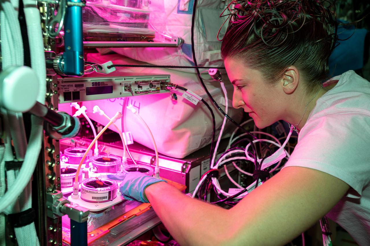
iss066e133016 (Feb. 1, 2022) --- NASA astronaut and Expedition 66 Flight Engineer Kayla Barron checks out plants growing inside the Veggie botany research facility for the Veggie PONDS experiment. The investigation tests ways to grow crops in space to supporting long-term crewed missions to the Moon, Mars and beyond.
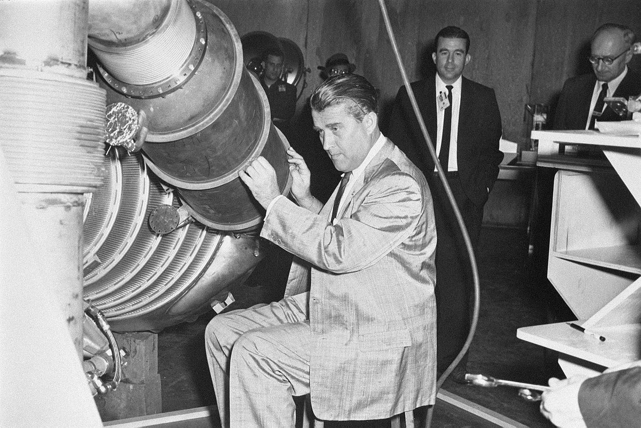
Dr. von Braun tried out a floating platform in the Marshall Space Flight Center Manufacturing Engineering Laboratory. This was a test rig to help determine how future astronauts will be able to perform maintenance tasks in the weightlessness in space. This photograph is believed to have been taken in 1961.

ISS036-E-023752 (21 July 2013) --- In the International Space Station’s Destiny laboratory, NASA astronaut Karen Nyberg, Expedition 36 flight engineer, wears special gear to telerobotically test Robonaut 2’s (out of frame) maneuvers transmitted from both space and the ground.

jsc2021e022515 (June 11, 2021) --- NASA’s Exploration Extravehicular Mobility Unit (xEMU) spacesuit undergoes antenna testing in NASA Johnson Space Center’s anechoic chamber to inspect multi-layer insulation keep-out zones for the Wi-Fi and ultra-high-frequency antennas that are part of the spacesuit’s communication system. The xEMU test article is named xGUS, the successor to the Extravehicular Mobility Unit test article (also named GUS), which was named after NASA astronaut Gus Grissom and his iconic silver spacesuit. This image was taken from where the "horn," or source antenna, is located that sends out radio frequency signals to the spacesuit. The anechoic chamber walls are covered with a material that absorbs electromagnetic energy allowing the anechoic chamber to simulate a space environment. The antenna test facility is utilized to test antenna radiation distribution pattern performance for spaceflight applications in electromagnetic environments. Pictured in the photo is antenna test engineer Will Bond.
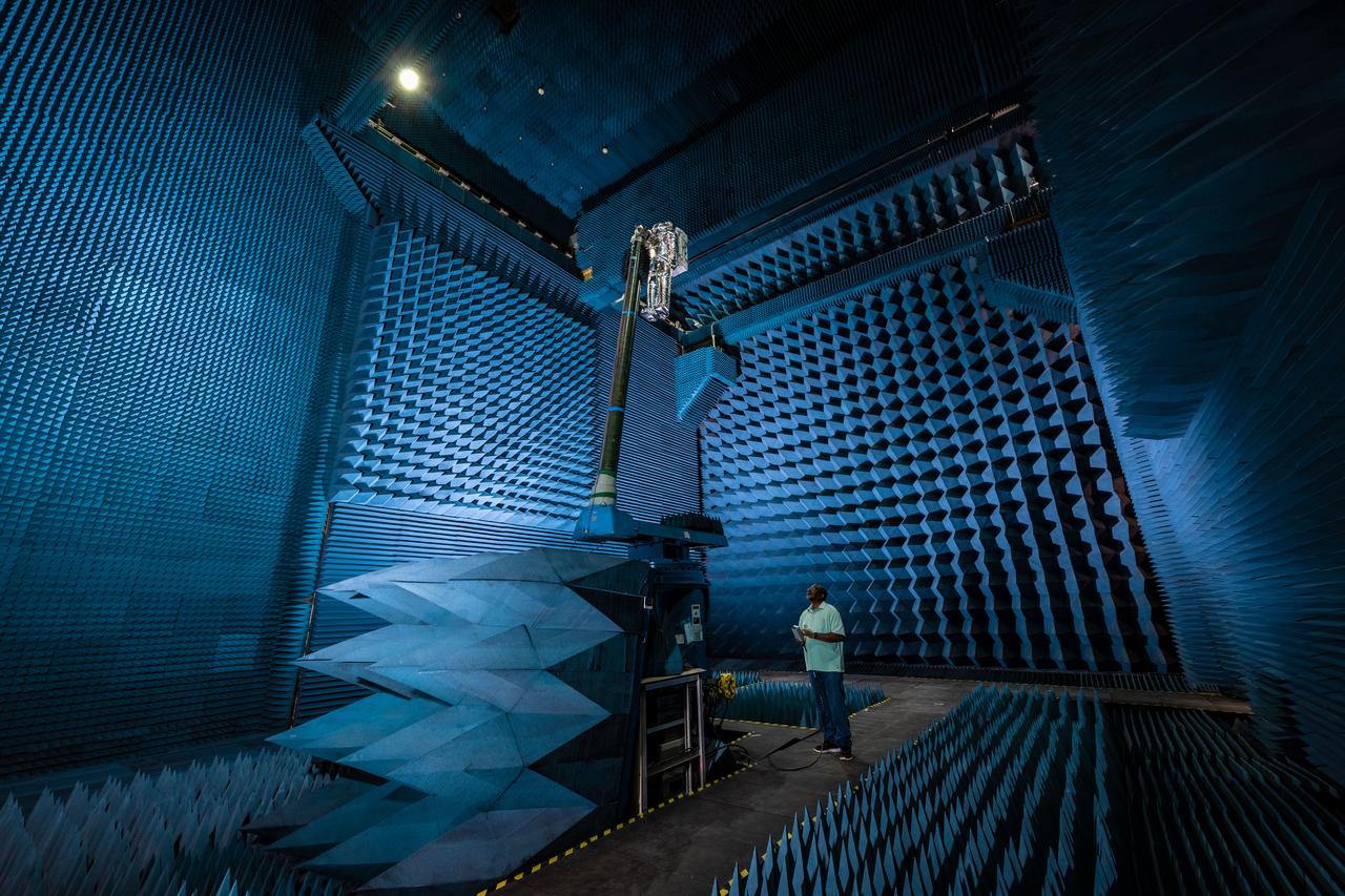
jsc2021e022488 (June 11, 2021) --- NASA’s Exploration Extravehicular Mobility Unit (xEMU) spacesuit undergoes antenna testing in NASA Johnson Space Center’s anechoic chamber to inspect multi-layer insulation keep-out zones for the Wi-Fi and ultra-high-frequency antennas that are part of the spacesuit’s communication system. The xEMU test article is named xGUS, the successor to the Extravehicular Mobility Unit test article (also named GUS), which was named after NASA astronaut Gus Grissom and his iconic silver spacesuit. This image was taken from where the "horn," or source antenna, is located that sends out radio frequency signals to the spacesuit. The anechoic chamber walls are covered with a material that absorbs electromagnetic energy allowing the anechoic chamber to simulate a space environment. The antenna test facility is utilized to test antenna radiation distribution pattern performance for spaceflight applications in electromagnetic environments. Pictured in the photo is antenna test engineer Will Bond.
The Saturn Project was approved on January 18, 1960 as a program of the highest national priority. The formal test program to prove out the clustered-booster concept was well underway. A series of static tests of the Saturn I booster (S-I stage) began June 3, 1960 at the Marshall Space Flight Center (MSFC). This photograph depicts the Saturn I S-I stage equipped with eight H-1 engines, being successfully test-fired for the duration of 121 seconds on June 15, 1960.
A construction 'topping out' milestone was reached April 13 with placement of the test cell dome atop NASA's new A-3 Test Stand at Stennis Space Center. NASA broke ground in 2007 for the new stand, which is being built to provide simulated high-altitude testing for next-generation rocket engines that could carry humans into deep space.
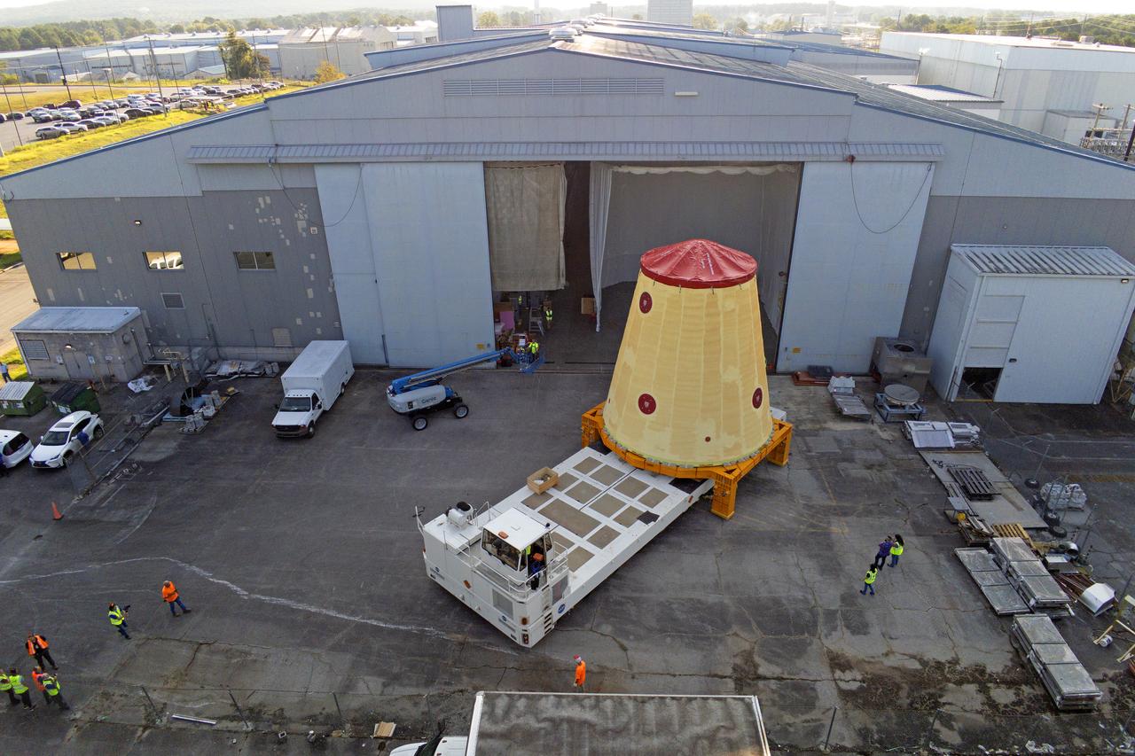
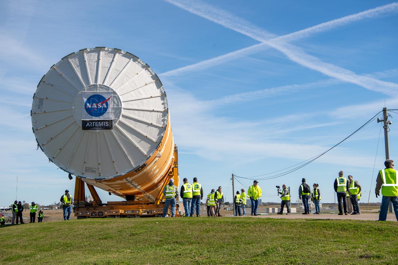
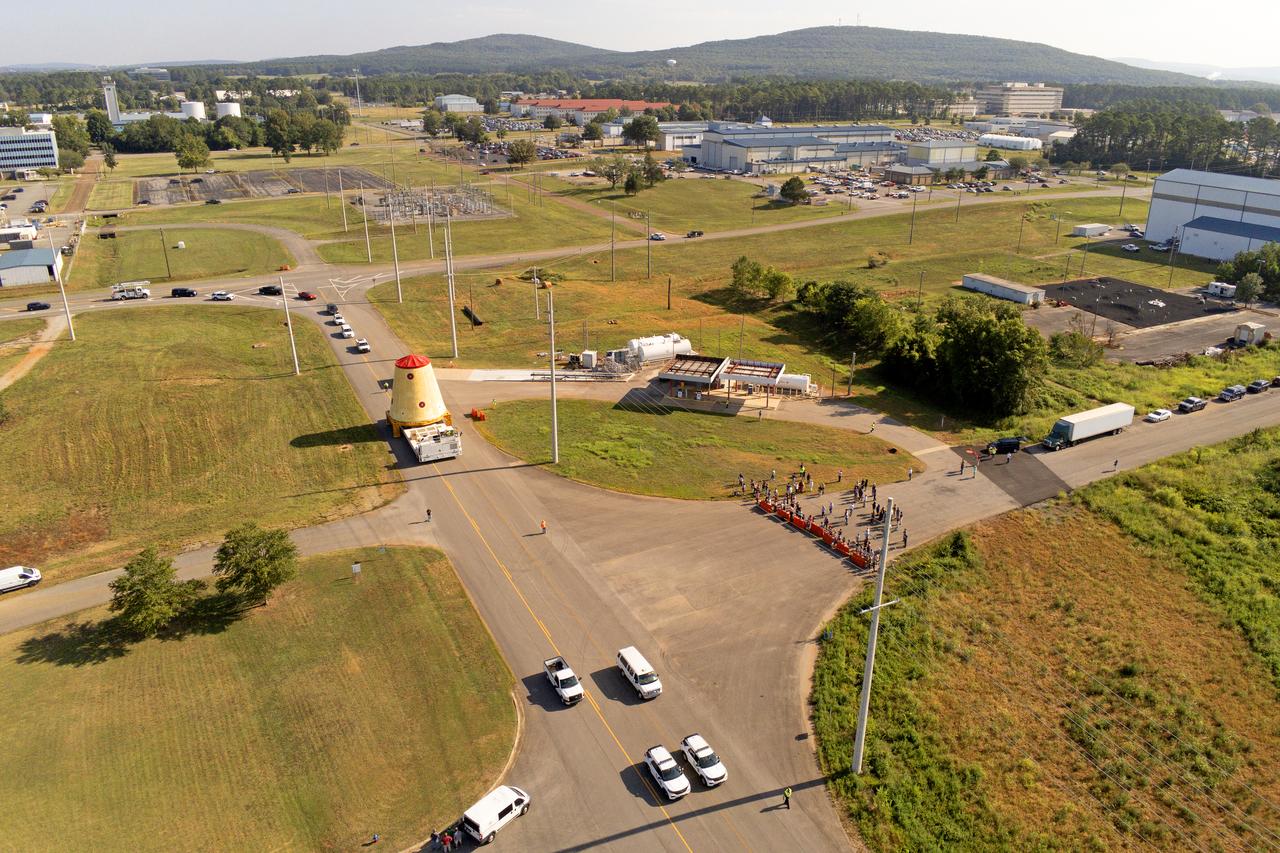
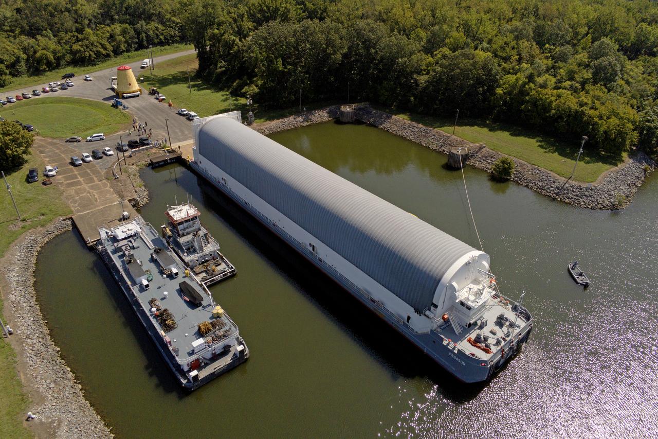
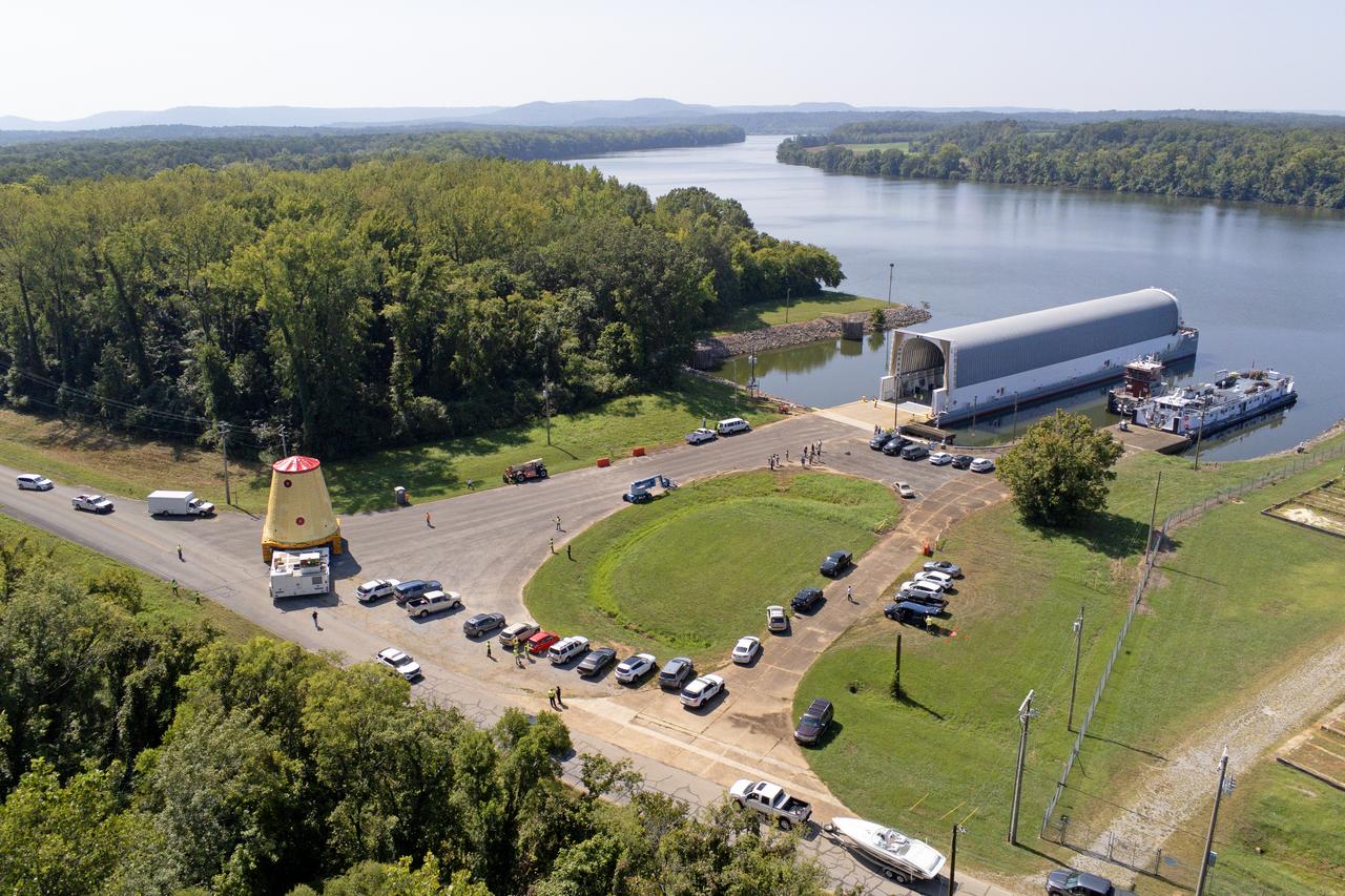
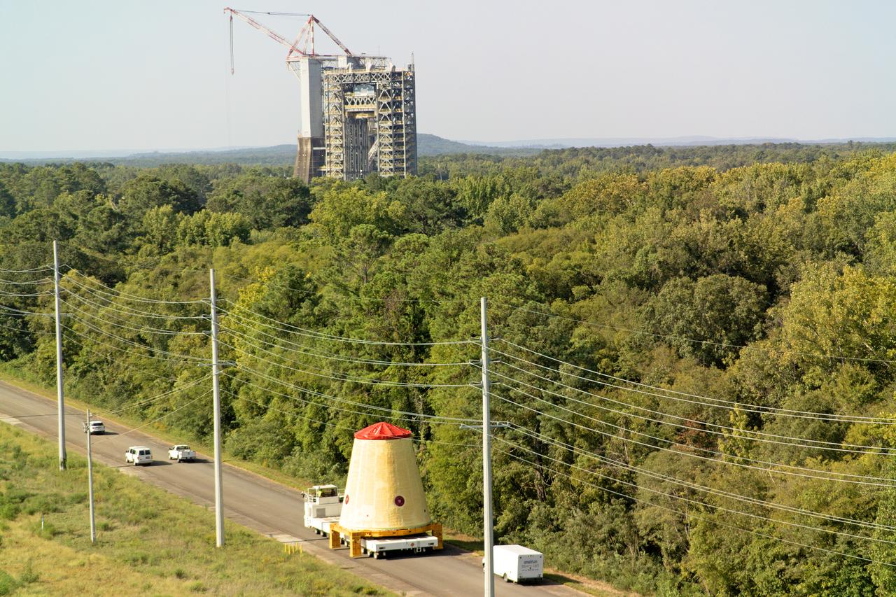
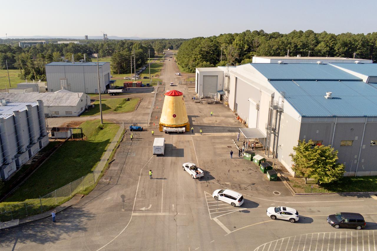
NASA rolled out a key piece of space flight hardware for the SLS (Space Launch System) rocket for the first crewed mission of NASA’s Artemis campaign from Marshall Space Flight Center in Huntsville, Alabama, on Wednesday, Aug. 21 for shipment to the agency’s spaceport in Florida. The cone-shaped launch vehicle stage adapter connects the rocket’s core stage to the upper stage and helps protect the upper stage’s engine that will help propel the Artemis II test flight around the Moon, slated for 2025. Manufactured by prime contractor Teledyne Brown Engineering and the Jacobs Space Exploration Group’s ESSCA (Engineering Services and Science Capability Augmentation) contract using NASA Marshall’s self-reacting friction-stir robotic and vertical weld tools. Crews moved the adapter out of NASA Marshall’s Building 4708 to the agency’s Pegasus barge Aug. 21. The barge will ferry the adapter first to NASA’s Michoud Assembly Facility in New Orleans, where crews will pick up additional SLS hardware for future Artemis missions, before traveling to NASA Kennedy. Once in Florida, the adapter will join the recently delivered core stage. There, teams with NASA’s Exploration Ground Systems will prepare the adapter for stacking and launch.
NASA rolled out a key piece of space flight hardware for the SLS (Space Launch System) rocket for the first crewed mission of NASA’s Artemis campaign from Marshall Space Flight Center in Huntsville, Alabama, on Wednesday, Aug. 21 for shipment to the agency’s spaceport in Florida. The cone-shaped launch vehicle stage adapter connects the rocket’s core stage to the upper stage and helps protect the upper stage’s engine that will help propel the Artemis II test flight around the Moon, slated for 2025. Manufactured by prime contractor Teledyne Brown Engineering and the Jacobs Space Exploration Group’s ESSCA (Engineering Services and Science Capability Augmentation) contract using NASA Marshall’s self-reacting friction-stir robotic and vertical weld tools. Crews moved the adapter out of NASA Marshall’s Building 4708 to the agency’s Pegasus barge Aug. 21. The barge will ferry the adapter first to NASA’s Michoud Assembly Facility in New Orleans, where crews will pick up additional SLS hardware for future Artemis missions, before traveling to NASA Kennedy. Once in Florida, the adapter will join the recently delivered core stage. There, teams with NASA’s Exploration Ground Systems will prepare the adapter for stacking and launch.
NASA rolled out a key piece of space flight hardware for the SLS (Space Launch System) rocket for the first crewed mission of NASA’s Artemis campaign from Marshall Space Flight Center in Huntsville, Alabama, on Wednesday, Aug. 21 for shipment to the agency’s spaceport in Florida. The cone-shaped launch vehicle stage adapter connects the rocket’s core stage to the upper stage and helps protect the upper stage’s engine that will help propel the Artemis II test flight around the Moon, slated for 2025. Manufactured by prime contractor Teledyne Brown Engineering and the Jacobs Space Exploration Group’s ESSCA (Engineering Services and Science Capability Augmentation) contract using NASA Marshall’s self-reacting friction-stir robotic and vertical weld tools. Crews moved the adapter out of NASA Marshall’s Building 4708 to the agency’s Pegasus barge Aug. 21. The barge will ferry the adapter first to NASA’s Michoud Assembly Facility in New Orleans, where crews will pick up additional SLS hardware for future Artemis missions, before traveling to NASA Kennedy. Once in Florida, the adapter will join the recently delivered core stage. There, teams with NASA’s Exploration Ground Systems will prepare the adapter for stacking and launch.

NASA rolled out a key piece of space flight hardware for the SLS (Space Launch System) rocket for the first crewed mission of NASA’s Artemis campaign from Marshall Space Flight Center in Huntsville, Alabama, on Wednesday, Aug. 21 for shipment to the agency’s spaceport in Florida. The cone-shaped launch vehicle stage adapter connects the rocket’s core stage to the upper stage and helps protect the upper stage’s engine that will help propel the Artemis II test flight around the Moon, slated for 2025. Manufactured by prime contractor Teledyne Brown Engineering and the Jacobs Space Exploration Group’s ESSCA (Engineering Services and Science Capability Augmentation) contract using NASA Marshall’s self-reacting friction-stir robotic and vertical weld tools. Crews moved the adapter out of NASA Marshall’s Building 4708 to the agency’s Pegasus barge Aug. 21. The barge will ferry the adapter first to NASA’s Michoud Assembly Facility in New Orleans, where crews will pick up additional SLS hardware for future Artemis missions, before traveling to NASA Kennedy. Once in Florida, the adapter will join the recently delivered core stage. There, teams with NASA’s Exploration Ground Systems will prepare the adapter for stacking and launch.
NASA rolled out a key piece of space flight hardware for the SLS (Space Launch System) rocket for the first crewed mission of NASA’s Artemis campaign from Marshall Space Flight Center in Huntsville, Alabama, on Wednesday, Aug. 21 for shipment to the agency’s spaceport in Florida. The cone-shaped launch vehicle stage adapter connects the rocket’s core stage to the upper stage and helps protect the upper stage’s engine that will help propel the Artemis II test flight around the Moon, slated for 2025. Manufactured by prime contractor Teledyne Brown Engineering and the Jacobs Space Exploration Group’s ESSCA (Engineering Services and Science Capability Augmentation) contract using NASA Marshall’s self-reacting friction-stir robotic and vertical weld tools. Crews moved the adapter out of NASA Marshall’s Building 4708 to the agency’s Pegasus barge Aug. 21. The barge will ferry the adapter first to NASA’s Michoud Assembly Facility in New Orleans, where crews will pick up additional SLS hardware for future Artemis missions, before traveling to NASA Kennedy. Once in Florida, the adapter will join the recently delivered core stage. There, teams with NASA’s Exploration Ground Systems will prepare the adapter for stacking and launch.
NASA rolled out a key piece of space flight hardware for the SLS (Space Launch System) rocket for the first crewed mission of NASA’s Artemis campaign from Marshall Space Flight Center in Huntsville, Alabama, on Wednesday, Aug. 21 for shipment to the agency’s spaceport in Florida. The cone-shaped launch vehicle stage adapter connects the rocket’s core stage to the upper stage and helps protect the upper stage’s engine that will help propel the Artemis II test flight around the Moon, slated for 2025. Manufactured by prime contractor Teledyne Brown Engineering and the Jacobs Space Exploration Group’s ESSCA (Engineering Services and Science Capability Augmentation) contract using NASA Marshall’s self-reacting friction-stir robotic and vertical weld tools. Crews moved the adapter out of NASA Marshall’s Building 4708 to the agency’s Pegasus barge Aug. 21. The barge will ferry the adapter first to NASA’s Michoud Assembly Facility in New Orleans, where crews will pick up additional SLS hardware for future Artemis missions, before traveling to NASA Kennedy. Once in Florida, the adapter will join the recently delivered core stage. There, teams with NASA’s Exploration Ground Systems will prepare the adapter for stacking and launch.
NASA rolled out a key piece of space flight hardware for the SLS (Space Launch System) rocket for the first crewed mission of NASA’s Artemis campaign from Marshall Space Flight Center in Huntsville, Alabama, on Wednesday, Aug. 21 for shipment to the agency’s spaceport in Florida. The cone-shaped launch vehicle stage adapter connects the rocket’s core stage to the upper stage and helps protect the upper stage’s engine that will help propel the Artemis II test flight around the Moon, slated for 2025. Manufactured by prime contractor Teledyne Brown Engineering and the Jacobs Space Exploration Group’s ESSCA (Engineering Services and Science Capability Augmentation) contract using NASA Marshall’s self-reacting friction-stir robotic and vertical weld tools. Crews moved the adapter out of NASA Marshall’s Building 4708 to the agency’s Pegasus barge Aug. 21. The barge will ferry the adapter first to NASA’s Michoud Assembly Facility in New Orleans, where crews will pick up additional SLS hardware for future Artemis missions, before traveling to NASA Kennedy. Once in Florida, the adapter will join the recently delivered core stage. There, teams with NASA’s Exploration Ground Systems will prepare the adapter for stacking and launch.
NASA rolled out a key piece of space flight hardware for the SLS (Space Launch System) rocket for the first crewed mission of NASA’s Artemis campaign from Marshall Space Flight Center in Huntsville, Alabama, on Wednesday, Aug. 21 for shipment to the agency’s spaceport in Florida. The cone-shaped launch vehicle stage adapter connects the rocket’s core stage to the upper stage and helps protect the upper stage’s engine that will help propel the Artemis II test flight around the Moon, slated for 2025. Manufactured by prime contractor Teledyne Brown Engineering and the Jacobs Space Exploration Group’s ESSCA (Engineering Services and Science Capability Augmentation) contract using NASA Marshall’s self-reacting friction-stir robotic and vertical weld tools. Crews moved the adapter out of NASA Marshall’s Building 4708 to the agency’s Pegasus barge Aug. 21. The barge will ferry the adapter first to NASA’s Michoud Assembly Facility in New Orleans, where crews will pick up additional SLS hardware for future Artemis missions, before traveling to NASA Kennedy. Once in Florida, the adapter will join the recently delivered core stage. There, teams with NASA’s Exploration Ground Systems will prepare the adapter for stacking and launch.
NASA rolled out a key piece of space flight hardware for the SLS (Space Launch System) rocket for the first crewed mission of NASA’s Artemis campaign from Marshall Space Flight Center in Huntsville, Alabama, on Wednesday, Aug. 21 for shipment to the agency’s spaceport in Florida. The cone-shaped launch vehicle stage adapter connects the rocket’s core stage to the upper stage and helps protect the upper stage’s engine that will help propel the Artemis II test flight around the Moon, slated for 2025. Manufactured by prime contractor Teledyne Brown Engineering and the Jacobs Space Exploration Group’s ESSCA (Engineering Services and Science Capability Augmentation) contract using NASA Marshall’s self-reacting friction-stir robotic and vertical weld tools. Crews moved the adapter out of NASA Marshall’s Building 4708 to the agency’s Pegasus barge Aug. 21. The barge will ferry the adapter first to NASA’s Michoud Assembly Facility in New Orleans, where crews will pick up additional SLS hardware for future Artemis missions, before traveling to NASA Kennedy. Once in Florida, the adapter will join the recently delivered core stage. There, teams with NASA’s Exploration Ground Systems will prepare the adapter for stacking and launch.
NASA rolled out a key piece of space flight hardware for the SLS (Space Launch System) rocket for the first crewed mission of NASA’s Artemis campaign from Marshall Space Flight Center in Huntsville, Alabama, on Wednesday, Aug. 21 for shipment to the agency’s spaceport in Florida. The cone-shaped launch vehicle stage adapter connects the rocket’s core stage to the upper stage and helps protect the upper stage’s engine that will help propel the Artemis II test flight around the Moon, slated for 2025. Manufactured by prime contractor Teledyne Brown Engineering and the Jacobs Space Exploration Group’s ESSCA (Engineering Services and Science Capability Augmentation) contract using NASA Marshall’s self-reacting friction-stir robotic and vertical weld tools. Crews moved the adapter out of NASA Marshall’s Building 4708 to the agency’s Pegasus barge Aug. 21. The barge will ferry the adapter first to NASA’s Michoud Assembly Facility in New Orleans, where crews will pick up additional SLS hardware for future Artemis missions, before traveling to NASA Kennedy. Once in Florida, the adapter will join the recently delivered core stage. There, teams with NASA’s Exploration Ground Systems will prepare the adapter for stacking and launch.
NASA rolled out a key piece of space flight hardware for the SLS (Space Launch System) rocket for the first crewed mission of NASA’s Artemis campaign from Marshall Space Flight Center in Huntsville, Alabama, on Wednesday, Aug. 21 for shipment to the agency’s spaceport in Florida. The cone-shaped launch vehicle stage adapter connects the rocket’s core stage to the upper stage and helps protect the upper stage’s engine that will help propel the Artemis II test flight around the Moon, slated for 2025. Manufactured by prime contractor Teledyne Brown Engineering and the Jacobs Space Exploration Group’s ESSCA (Engineering Services and Science Capability Augmentation) contract using NASA Marshall’s self-reacting friction-stir robotic and vertical weld tools. Crews moved the adapter out of NASA Marshall’s Building 4708 to the agency’s Pegasus barge Aug. 21. The barge will ferry the adapter first to NASA’s Michoud Assembly Facility in New Orleans, where crews will pick up additional SLS hardware for future Artemis missions, before traveling to NASA Kennedy. Once in Florida, the adapter will join the recently delivered core stage. There, teams with NASA’s Exploration Ground Systems will prepare the adapter for stacking and launch.
NASA rolled out a key piece of space flight hardware for the SLS (Space Launch System) rocket for the first crewed mission of NASA’s Artemis campaign from Marshall Space Flight Center in Huntsville, Alabama, on Wednesday, Aug. 21 for shipment to the agency’s spaceport in Florida. The cone-shaped launch vehicle stage adapter connects the rocket’s core stage to the upper stage and helps protect the upper stage’s engine that will help propel the Artemis II test flight around the Moon, slated for 2025. Manufactured by prime contractor Teledyne Brown Engineering and the Jacobs Space Exploration Group’s ESSCA (Engineering Services and Science Capability Augmentation) contract using NASA Marshall’s self-reacting friction-stir robotic and vertical weld tools. Crews moved the adapter out of NASA Marshall’s Building 4708 to the agency’s Pegasus barge Aug. 21. The barge will ferry the adapter first to NASA’s Michoud Assembly Facility in New Orleans, where crews will pick up additional SLS hardware for future Artemis missions, before traveling to NASA Kennedy. Once in Florida, the adapter will join the recently delivered core stage. There, teams with NASA’s Exploration Ground Systems will prepare the adapter for stacking and launch.
NASA rolled out a key piece of space flight hardware for the SLS (Space Launch System) rocket for the first crewed mission of NASA’s Artemis campaign from Marshall Space Flight Center in Huntsville, Alabama, on Wednesday, Aug. 21 for shipment to the agency’s spaceport in Florida. The cone-shaped launch vehicle stage adapter connects the rocket’s core stage to the upper stage and helps protect the upper stage’s engine that will help propel the Artemis II test flight around the Moon, slated for 2025. Manufactured by prime contractor Teledyne Brown Engineering and the Jacobs Space Exploration Group’s ESSCA (Engineering Services and Science Capability Augmentation) contract using NASA Marshall’s self-reacting friction-stir robotic and vertical weld tools. Crews moved the adapter out of NASA Marshall’s Building 4708 to the agency’s Pegasus barge Aug. 21. The barge will ferry the adapter first to NASA’s Michoud Assembly Facility in New Orleans, where crews will pick up additional SLS hardware for future Artemis missions, before traveling to NASA Kennedy. Once in Florida, the adapter will join the recently delivered core stage. There, teams with NASA’s Exploration Ground Systems will prepare the adapter for stacking and launch.
NASA rolled out a key piece of space flight hardware for the SLS (Space Launch System) rocket for the first crewed mission of NASA’s Artemis campaign from Marshall Space Flight Center in Huntsville, Alabama, on Wednesday, Aug. 21 for shipment to the agency’s spaceport in Florida. The cone-shaped launch vehicle stage adapter connects the rocket’s core stage to the upper stage and helps protect the upper stage’s engine that will help propel the Artemis II test flight around the Moon, slated for 2025. Manufactured by prime contractor Teledyne Brown Engineering and the Jacobs Space Exploration Group’s ESSCA (Engineering Services and Science Capability Augmentation) contract using NASA Marshall’s self-reacting friction-stir robotic and vertical weld tools. Crews moved the adapter out of NASA Marshall’s Building 4708 to the agency’s Pegasus barge Aug. 21. The barge will ferry the adapter first to NASA’s Michoud Assembly Facility in New Orleans, where crews will pick up additional SLS hardware for future Artemis missions, before traveling to NASA Kennedy. Once in Florida, the adapter will join the recently delivered core stage. There, teams with NASA’s Exploration Ground Systems will prepare the adapter for stacking and launch.
NASA rolled out a key piece of space flight hardware for the SLS (Space Launch System) rocket for the first crewed mission of NASA’s Artemis campaign from Marshall Space Flight Center in Huntsville, Alabama, on Wednesday, Aug. 21 for shipment to the agency’s spaceport in Florida. The cone-shaped launch vehicle stage adapter connects the rocket’s core stage to the upper stage and helps protect the upper stage’s engine that will help propel the Artemis II test flight around the Moon, slated for 2025. Manufactured by prime contractor Teledyne Brown Engineering and the Jacobs Space Exploration Group’s ESSCA (Engineering Services and Science Capability Augmentation) contract using NASA Marshall’s self-reacting friction-stir robotic and vertical weld tools. Crews moved the adapter out of NASA Marshall’s Building 4708 to the agency’s Pegasus barge Aug. 21. The barge will ferry the adapter first to NASA’s Michoud Assembly Facility in New Orleans, where crews will pick up additional SLS hardware for future Artemis missions, before traveling to NASA Kennedy. Once in Florida, the adapter will join the recently delivered core stage. There, teams with NASA’s Exploration Ground Systems will prepare the adapter for stacking and launch.
NASA rolled out a key piece of space flight hardware for the SLS (Space Launch System) rocket for the first crewed mission of NASA’s Artemis campaign from Marshall Space Flight Center in Huntsville, Alabama, on Wednesday, Aug. 21 for shipment to the agency’s spaceport in Florida. The cone-shaped launch vehicle stage adapter connects the rocket’s core stage to the upper stage and helps protect the upper stage’s engine that will help propel the Artemis II test flight around the Moon, slated for 2025. Manufactured by prime contractor Teledyne Brown Engineering and the Jacobs Space Exploration Group’s ESSCA (Engineering Services and Science Capability Augmentation) contract using NASA Marshall’s self-reacting friction-stir robotic and vertical weld tools. Crews moved the adapter out of NASA Marshall’s Building 4708 to the agency’s Pegasus barge Aug. 21. The barge will ferry the adapter first to NASA’s Michoud Assembly Facility in New Orleans, where crews will pick up additional SLS hardware for future Artemis missions, before traveling to NASA Kennedy. Once in Florida, the adapter will join the recently delivered core stage. There, teams with NASA’s Exploration Ground Systems will prepare the adapter for stacking and launch.
NASA rolled out a key piece of space flight hardware for the SLS (Space Launch System) rocket for the first crewed mission of NASA’s Artemis campaign from Marshall Space Flight Center in Huntsville, Alabama, on Wednesday, Aug. 21 for shipment to the agency’s spaceport in Florida. The cone-shaped launch vehicle stage adapter connects the rocket’s core stage to the upper stage and helps protect the upper stage’s engine that will help propel the Artemis II test flight around the Moon, slated for 2025. Manufactured by prime contractor Teledyne Brown Engineering and the Jacobs Space Exploration Group’s ESSCA (Engineering Services and Science Capability Augmentation) contract using NASA Marshall’s self-reacting friction-stir robotic and vertical weld tools. Crews moved the adapter out of NASA Marshall’s Building 4708 to the agency’s Pegasus barge Aug. 21. The barge will ferry the adapter first to NASA’s Michoud Assembly Facility in New Orleans, where crews will pick up additional SLS hardware for future Artemis missions, before traveling to NASA Kennedy. Once in Florida, the adapter will join the recently delivered core stage. There, teams with NASA’s Exploration Ground Systems will prepare the adapter for stacking and launch.
NASA rolled out a key piece of space flight hardware for the SLS (Space Launch System) rocket for the first crewed mission of NASA’s Artemis campaign from Marshall Space Flight Center in Huntsville, Alabama, on Wednesday, Aug. 21 for shipment to the agency’s spaceport in Florida. The cone-shaped launch vehicle stage adapter connects the rocket’s core stage to the upper stage and helps protect the upper stage’s engine that will help propel the Artemis II test flight around the Moon, slated for 2025. Manufactured by prime contractor Teledyne Brown Engineering and the Jacobs Space Exploration Group’s ESSCA (Engineering Services and Science Capability Augmentation) contract using NASA Marshall’s self-reacting friction-stir robotic and vertical weld tools. Crews moved the adapter out of NASA Marshall’s Building 4708 to the agency’s Pegasus barge Aug. 21. The barge will ferry the adapter first to NASA’s Michoud Assembly Facility in New Orleans, where crews will pick up additional SLS hardware for future Artemis missions, before traveling to NASA Kennedy. Once in Florida, the adapter will join the recently delivered core stage. There, teams with NASA’s Exploration Ground Systems will prepare the adapter for stacking and launch.
NASA rolled out a key piece of space flight hardware for the SLS (Space Launch System) rocket for the first crewed mission of NASA’s Artemis campaign from Marshall Space Flight Center in Huntsville, Alabama, on Wednesday, Aug. 21 for shipment to the agency’s spaceport in Florida. The cone-shaped launch vehicle stage adapter connects the rocket’s core stage to the upper stage and helps protect the upper stage’s engine that will help propel the Artemis II test flight around the Moon, slated for 2025. Manufactured by prime contractor Teledyne Brown Engineering and the Jacobs Space Exploration Group’s ESSCA (Engineering Services and Science Capability Augmentation) contract using NASA Marshall’s self-reacting friction-stir robotic and vertical weld tools. Crews moved the adapter out of NASA Marshall’s Building 4708 to the agency’s Pegasus barge Aug. 21. The barge will ferry the adapter first to NASA’s Michoud Assembly Facility in New Orleans, where crews will pick up additional SLS hardware for future Artemis missions, before traveling to NASA Kennedy. Once in Florida, the adapter will join the recently delivered core stage. There, teams with NASA’s Exploration Ground Systems will prepare the adapter for stacking and launch.
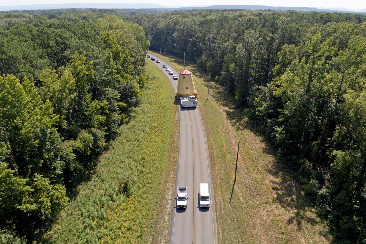
NASA rolled out a key piece of space flight hardware for the SLS (Space Launch System) rocket for the first crewed mission of NASA’s Artemis campaign from Marshall Space Flight Center in Huntsville, Alabama, on Wednesday, Aug. 21 for shipment to the agency’s spaceport in Florida. The cone-shaped launch vehicle stage adapter connects the rocket’s core stage to the upper stage and helps protect the upper stage’s engine that will help propel the Artemis II test flight around the Moon, slated for 2025. Manufactured by prime contractor Teledyne Brown Engineering and the Jacobs Space Exploration Group’s ESSCA (Engineering Services and Science Capability Augmentation) contract using NASA Marshall’s self-reacting friction-stir robotic and vertical weld tools. Crews moved the adapter out of NASA Marshall’s Building 4708 to the agency’s Pegasus barge Aug. 21. The barge will ferry the adapter first to NASA’s Michoud Assembly Facility in New Orleans, where crews will pick up additional SLS hardware for future Artemis missions, before traveling to NASA Kennedy. Once in Florida, the adapter will join the recently delivered core stage. There, teams with NASA’s Exploration Ground Systems will prepare the adapter for stacking and launch.
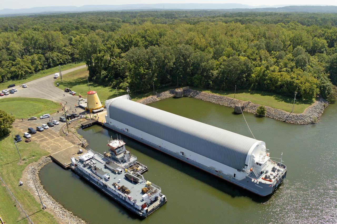
NASA rolled out a key piece of space flight hardware for the SLS (Space Launch System) rocket for the first crewed mission of NASA’s Artemis campaign from Marshall Space Flight Center in Huntsville, Alabama, on Wednesday, Aug. 21 for shipment to the agency’s spaceport in Florida. The cone-shaped launch vehicle stage adapter connects the rocket’s core stage to the upper stage and helps protect the upper stage’s engine that will help propel the Artemis II test flight around the Moon, slated for 2025. Manufactured by prime contractor Teledyne Brown Engineering and the Jacobs Space Exploration Group’s ESSCA (Engineering Services and Science Capability Augmentation) contract using NASA Marshall’s self-reacting friction-stir robotic and vertical weld tools. Crews moved the adapter out of NASA Marshall’s Building 4708 to the agency’s Pegasus barge Aug. 21. The barge will ferry the adapter first to NASA’s Michoud Assembly Facility in New Orleans, where crews will pick up additional SLS hardware for future Artemis missions, before traveling to NASA Kennedy. Once in Florida, the adapter will join the recently delivered core stage. There, teams with NASA’s Exploration Ground Systems will prepare the adapter for stacking and launch.
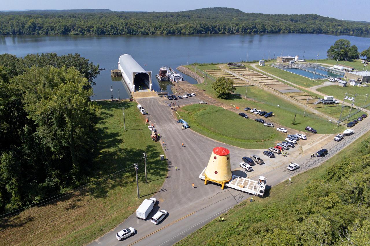
NASA rolled out a key piece of space flight hardware for the SLS (Space Launch System) rocket for the first crewed mission of NASA’s Artemis campaign from Marshall Space Flight Center in Huntsville, Alabama, on Wednesday, Aug. 21 for shipment to the agency’s spaceport in Florida. The cone-shaped launch vehicle stage adapter connects the rocket’s core stage to the upper stage and helps protect the upper stage’s engine that will help propel the Artemis II test flight around the Moon, slated for 2025. Manufactured by prime contractor Teledyne Brown Engineering and the Jacobs Space Exploration Group’s ESSCA (Engineering Services and Science Capability Augmentation) contract using NASA Marshall’s self-reacting friction-stir robotic and vertical weld tools. Crews moved the adapter out of NASA Marshall’s Building 4708 to the agency’s Pegasus barge Aug. 21. The barge will ferry the adapter first to NASA’s Michoud Assembly Facility in New Orleans, where crews will pick up additional SLS hardware for future Artemis missions, before traveling to NASA Kennedy. Once in Florida, the adapter will join the recently delivered core stage. There, teams with NASA’s Exploration Ground Systems will prepare the adapter for stacking and launch.
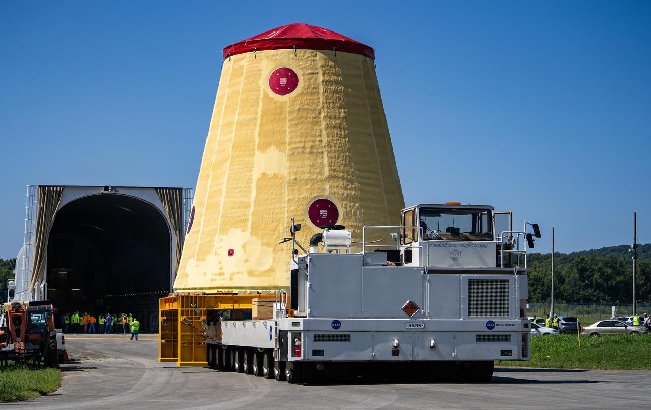
NASA rolled out a key piece of space flight hardware for the SLS (Space Launch System) rocket for the first crewed mission of NASA’s Artemis campaign from Marshall Space Flight Center in Huntsville, Alabama, on Wednesday, Aug. 21 for shipment to the agency’s spaceport in Florida. The cone-shaped launch vehicle stage adapter connects the rocket’s core stage to the upper stage and helps protect the upper stage’s engine that will help propel the Artemis II test flight around the Moon, slated for 2025. Manufactured by prime contractor Teledyne Brown Engineering and the Jacobs Space Exploration Group’s ESSCA (Engineering Services and Science Capability Augmentation) contract using NASA Marshall’s self-reacting friction-stir robotic and vertical weld tools. Crews moved the adapter out of NASA Marshall’s Building 4708 to the agency’s Pegasus barge Aug. 21. The barge will ferry the adapter first to NASA’s Michoud Assembly Facility in New Orleans, where crews will pick up additional SLS hardware for future Artemis missions, before traveling to NASA Kennedy. Once in Florida, the adapter will join the recently delivered core stage. There, teams with NASA’s Exploration Ground Systems will prepare the adapter for stacking and launch.
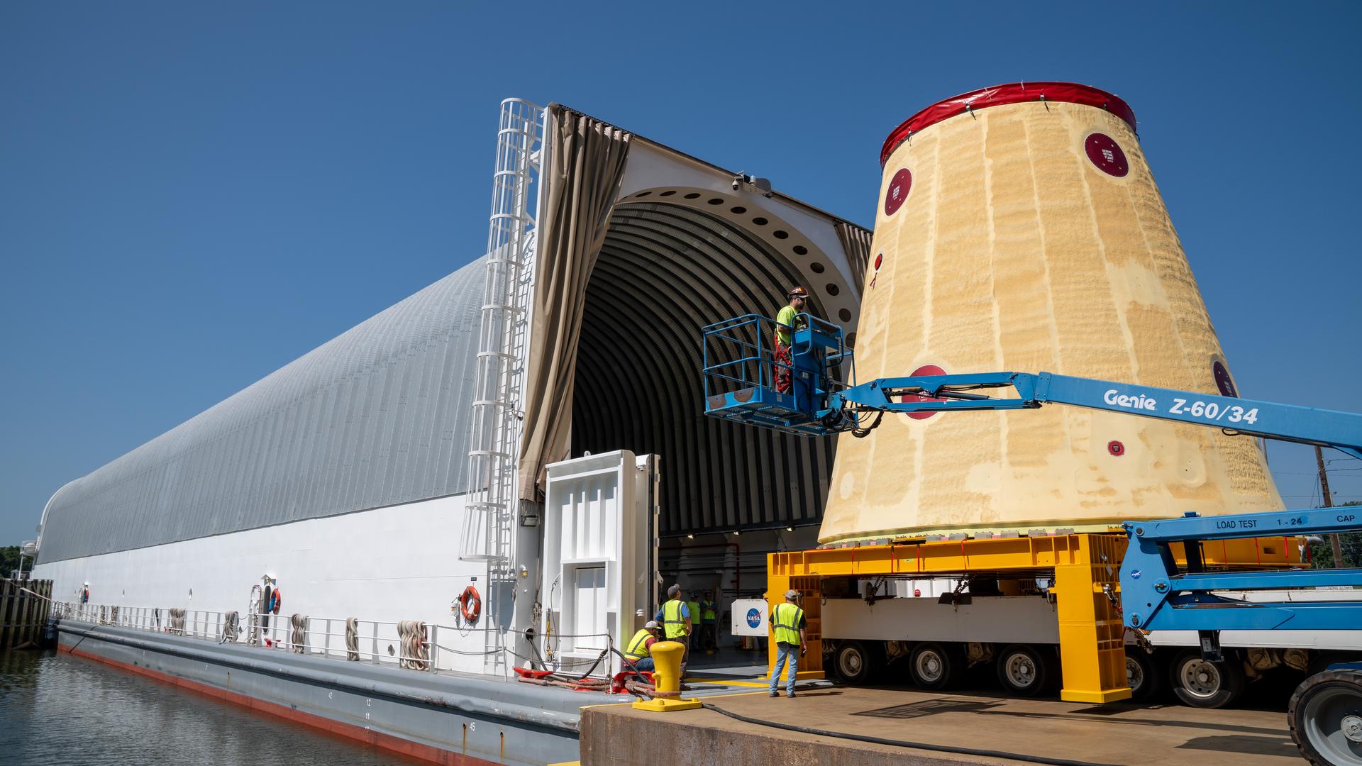
NASA rolled out a key piece of space flight hardware for the SLS (Space Launch System) rocket for the first crewed mission of NASA’s Artemis campaign from Marshall Space Flight Center in Huntsville, Alabama, on Wednesday, Aug. 21 for shipment to the agency’s spaceport in Florida. The cone-shaped launch vehicle stage adapter connects the rocket’s core stage to the upper stage and helps protect the upper stage’s engine that will help propel the Artemis II test flight around the Moon, slated for 2025. Manufactured by prime contractor Teledyne Brown Engineering and the Jacobs Space Exploration Group’s ESSCA (Engineering Services and Science Capability Augmentation) contract using NASA Marshall’s self-reacting friction-stir robotic and vertical weld tools. Crews moved the adapter out of NASA Marshall’s Building 4708 to the agency’s Pegasus barge Aug. 21. The barge will ferry the adapter first to NASA’s Michoud Assembly Facility in New Orleans, where crews will pick up additional SLS hardware for future Artemis missions, before traveling to NASA Kennedy. Once in Florida, the adapter will join the recently delivered core stage. There, teams with NASA’s Exploration Ground Systems will prepare the adapter for stacking and launch.
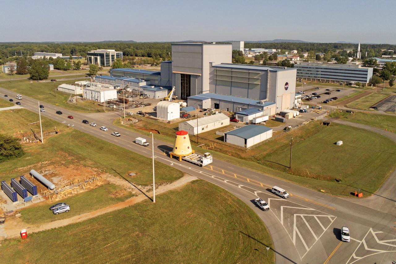
NASA rolled out a key piece of space flight hardware for the SLS (Space Launch System) rocket for the first crewed mission of NASA’s Artemis campaign from Marshall Space Flight Center in Huntsville, Alabama, on Wednesday, Aug. 21 for shipment to the agency’s spaceport in Florida. The cone-shaped launch vehicle stage adapter connects the rocket’s core stage to the upper stage and helps protect the upper stage’s engine that will help propel the Artemis II test flight around the Moon, slated for 2025. Manufactured by prime contractor Teledyne Brown Engineering and the Jacobs Space Exploration Group’s ESSCA (Engineering Services and Science Capability Augmentation) contract using NASA Marshall’s self-reacting friction-stir robotic and vertical weld tools. Crews moved the adapter out of NASA Marshall’s Building 4708 to the agency’s Pegasus barge Aug. 21. The barge will ferry the adapter first to NASA’s Michoud Assembly Facility in New Orleans, where crews will pick up additional SLS hardware for future Artemis missions, before traveling to NASA Kennedy. Once in Florida, the adapter will join the recently delivered core stage. There, teams with NASA’s Exploration Ground Systems will prepare the adapter for stacking and launch.

NASA rolled out a key piece of space flight hardware for the SLS (Space Launch System) rocket for the first crewed mission of NASA’s Artemis campaign from Marshall Space Flight Center in Huntsville, Alabama, on Wednesday, Aug. 21 for shipment to the agency’s spaceport in Florida. The cone-shaped launch vehicle stage adapter connects the rocket’s core stage to the upper stage and helps protect the upper stage’s engine that will help propel the Artemis II test flight around the Moon, slated for 2025. Manufactured by prime contractor Teledyne Brown Engineering and the Jacobs Space Exploration Group’s ESSCA (Engineering Services and Science Capability Augmentation) contract using NASA Marshall’s self-reacting friction-stir robotic and vertical weld tools. Crews moved the adapter out of NASA Marshall’s Building 4708 to the agency’s Pegasus barge Aug. 21. The barge will ferry the adapter first to NASA’s Michoud Assembly Facility in New Orleans, where crews will pick up additional SLS hardware for future Artemis missions, before traveling to NASA Kennedy. Once in Florida, the adapter will join the recently delivered core stage. There, teams with NASA’s Exploration Ground Systems will prepare the adapter for stacking and launch.
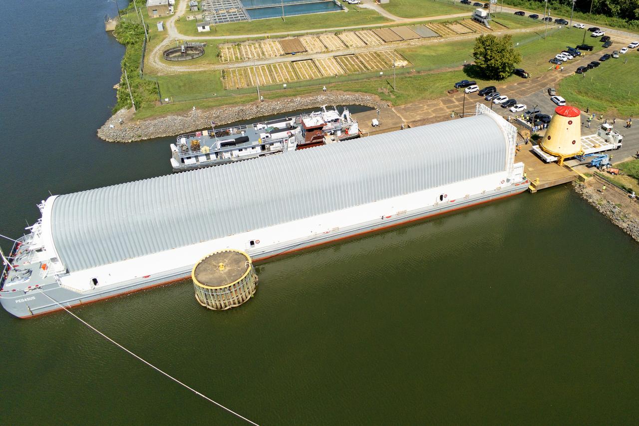
These images and videos show NASA rolling out a key piece of space flight hardware for the SLS (Space Launch System) rocket for the first crewed mission of NASA’s Artemis campaign from Marshall Space Flight Center in Huntsville, Alabama, on Wednesday, Aug. 21 for shipment to the agency’s spaceport in Florida. The cone-shaped launch vehicle stage adapter connects the rocket’s core stage to the upper stage and helps protect the upper stage’s engine that will help propel the Artemis II test flight around the Moon, slated for 2025. Manufactured by prime contractor Teledyne Brown Engineering and the Jacobs Space Exploration Group’s ESSCA (Engineering Services and Science Capability Augmentation) contract using NASA Marshall’s self-reacting friction-stir robotic and vertical weld tools. Crews moved the adapter out of NASA Marshall’s Building 4708 to the agency’s Pegasus barge Aug. 21. The barge will ferry the adapter first to NASA’s Michoud Assembly Facility in New Orleans, where crews will pick up additional SLS hardware for future Artemis missions, before traveling to NASA Kennedy. Once in Florida, the adapter will join the recently delivered core stage. There, teams with NASA’s Exploration Ground Systems will prepare the adapter for stacking and launch.
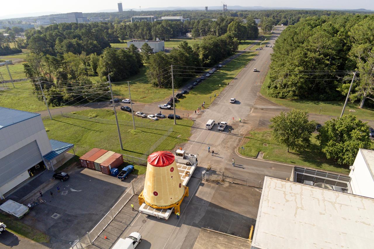
NASA rolled out a key piece of space flight hardware for the SLS (Space Launch System) rocket for the first crewed mission of NASA’s Artemis campaign from Marshall Space Flight Center in Huntsville, Alabama, on Wednesday, Aug. 21 for shipment to the agency’s spaceport in Florida. The cone-shaped launch vehicle stage adapter connects the rocket’s core stage to the upper stage and helps protect the upper stage’s engine that will help propel the Artemis II test flight around the Moon, slated for 2025. Manufactured by prime contractor Teledyne Brown Engineering and the Jacobs Space Exploration Group’s ESSCA (Engineering Services and Science Capability Augmentation) contract using NASA Marshall’s self-reacting friction-stir robotic and vertical weld tools. Crews moved the adapter out of NASA Marshall’s Building 4708 to the agency’s Pegasus barge Aug. 21. The barge will ferry the adapter first to NASA’s Michoud Assembly Facility in New Orleans, where crews will pick up additional SLS hardware for future Artemis missions, before traveling to NASA Kennedy. Once in Florida, the adapter will join the recently delivered core stage. There, teams with NASA’s Exploration Ground Systems will prepare the adapter for stacking and launch.
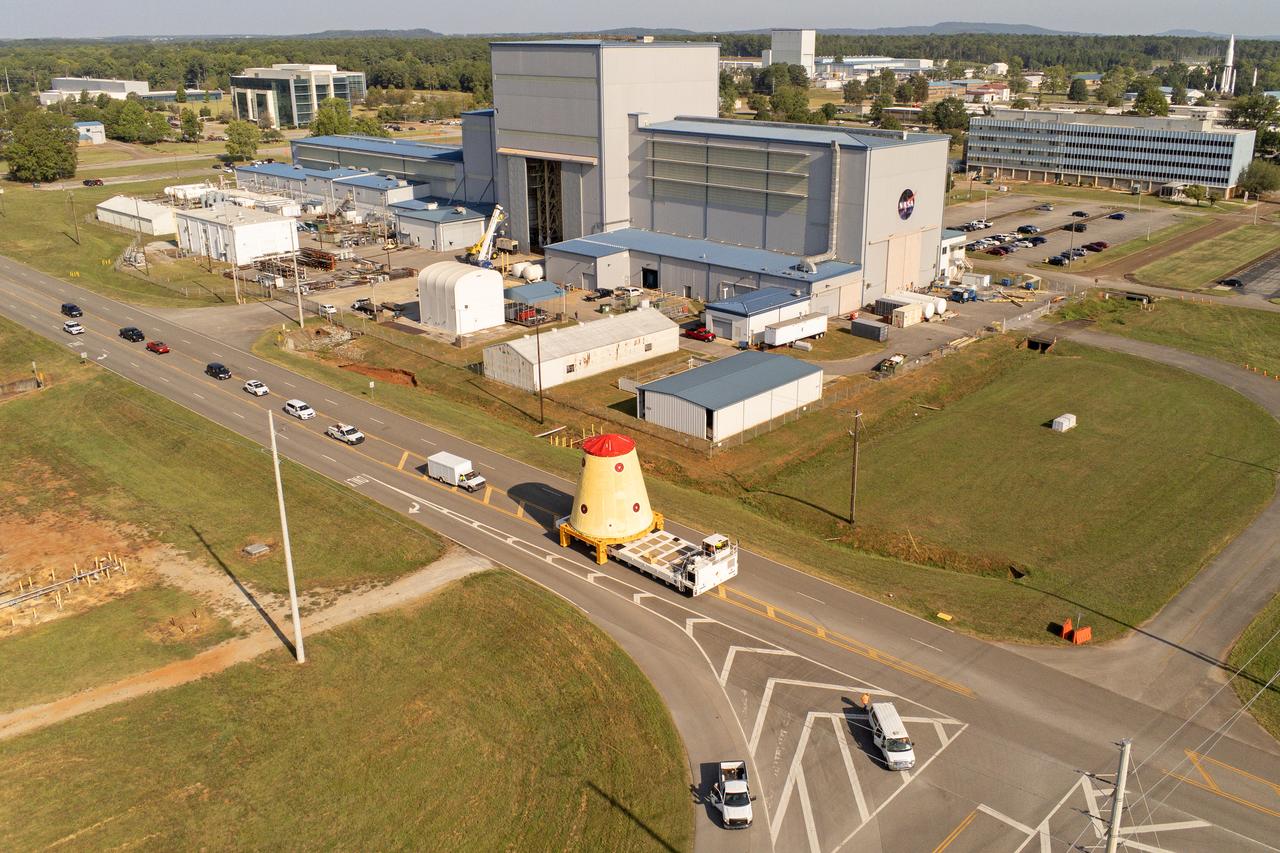
NASA rolled out a key piece of space flight hardware for the SLS (Space Launch System) rocket for the first crewed mission of NASA’s Artemis campaign from Marshall Space Flight Center in Huntsville, Alabama, on Wednesday, Aug. 21 for shipment to the agency’s spaceport in Florida. The cone-shaped launch vehicle stage adapter connects the rocket’s core stage to the upper stage and helps protect the upper stage’s engine that will help propel the Artemis II test flight around the Moon, slated for 2025. Manufactured by prime contractor Teledyne Brown Engineering and the Jacobs Space Exploration Group’s ESSCA (Engineering Services and Science Capability Augmentation) contract using NASA Marshall’s self-reacting friction-stir robotic and vertical weld tools. Crews moved the adapter out of NASA Marshall’s Building 4708 to the agency’s Pegasus barge Aug. 21. The barge will ferry the adapter first to NASA’s Michoud Assembly Facility in New Orleans, where crews will pick up additional SLS hardware for future Artemis missions, before traveling to NASA Kennedy. Once in Florida, the adapter will join the recently delivered core stage. There, teams with NASA’s Exploration Ground Systems will prepare the adapter for stacking and launch.
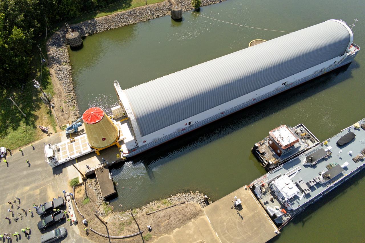
NASA rolled out a key piece of space flight hardware for the SLS (Space Launch System) rocket for the first crewed mission of NASA’s Artemis campaign from Marshall Space Flight Center in Huntsville, Alabama, on Wednesday, Aug. 21 for shipment to the agency’s spaceport in Florida. The cone-shaped launch vehicle stage adapter connects the rocket’s core stage to the upper stage and helps protect the upper stage’s engine that will help propel the Artemis II test flight around the Moon, slated for 2025. Manufactured by prime contractor Teledyne Brown Engineering and the Jacobs Space Exploration Group’s ESSCA (Engineering Services and Science Capability Augmentation) contract using NASA Marshall’s self-reacting friction-stir robotic and vertical weld tools. Crews moved the adapter out of NASA Marshall’s Building 4708 to the agency’s Pegasus barge Aug. 21. The barge will ferry the adapter first to NASA’s Michoud Assembly Facility in New Orleans, where crews will pick up additional SLS hardware for future Artemis missions, before traveling to NASA Kennedy. Once in Florida, the adapter will join the recently delivered core stage. There, teams with NASA’s Exploration Ground Systems will prepare the adapter for stacking and launch.
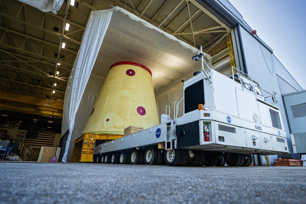
NASA rolled out a key piece of space flight hardware for the SLS (Space Launch System) rocket for the first crewed mission of NASA’s Artemis campaign from Marshall Space Flight Center in Huntsville, Alabama, on Wednesday, Aug. 21 for shipment to the agency’s spaceport in Florida. The cone-shaped launch vehicle stage adapter connects the rocket’s core stage to the upper stage and helps protect the upper stage’s engine that will help propel the Artemis II test flight around the Moon, slated for 2025. Manufactured by prime contractor Teledyne Brown Engineering and the Jacobs Space Exploration Group’s ESSCA (Engineering Services and Science Capability Augmentation) contract using NASA Marshall’s self-reacting friction-stir robotic and vertical weld tools. Crews moved the adapter out of NASA Marshall’s Building 4708 to the agency’s Pegasus barge Aug. 21. The barge will ferry the adapter first to NASA’s Michoud Assembly Facility in New Orleans, where crews will pick up additional SLS hardware for future Artemis missions, before traveling to NASA Kennedy. Once in Florida, the adapter will join the recently delivered core stage. There, teams with NASA’s Exploration Ground Systems will prepare the adapter for stacking and launch.
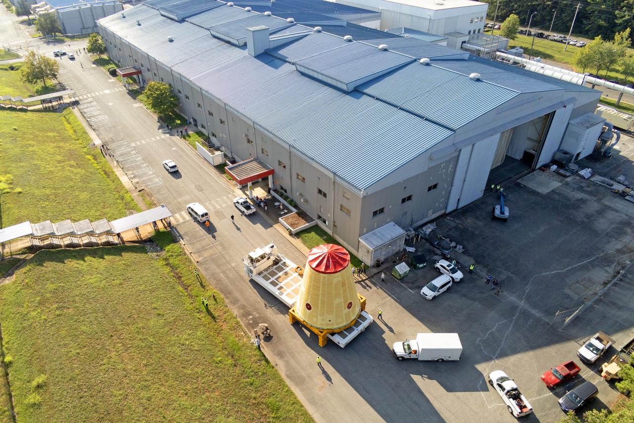
NASA rolled out a key piece of space flight hardware for the SLS (Space Launch System) rocket for the first crewed mission of NASA’s Artemis campaign from Marshall Space Flight Center in Huntsville, Alabama, on Wednesday, Aug. 21 for shipment to the agency’s spaceport in Florida. The cone-shaped launch vehicle stage adapter connects the rocket’s core stage to the upper stage and helps protect the upper stage’s engine that will help propel the Artemis II test flight around the Moon, slated for 2025. Manufactured by prime contractor Teledyne Brown Engineering and the Jacobs Space Exploration Group’s ESSCA (Engineering Services and Science Capability Augmentation) contract using NASA Marshall’s self-reacting friction-stir robotic and vertical weld tools. Crews moved the adapter out of NASA Marshall’s Building 4708 to the agency’s Pegasus barge Aug. 21. The barge will ferry the adapter first to NASA’s Michoud Assembly Facility in New Orleans, where crews will pick up additional SLS hardware for future Artemis missions, before traveling to NASA Kennedy. Once in Florida, the adapter will join the recently delivered core stage. There, teams with NASA’s Exploration Ground Systems will prepare the adapter for stacking and launch.
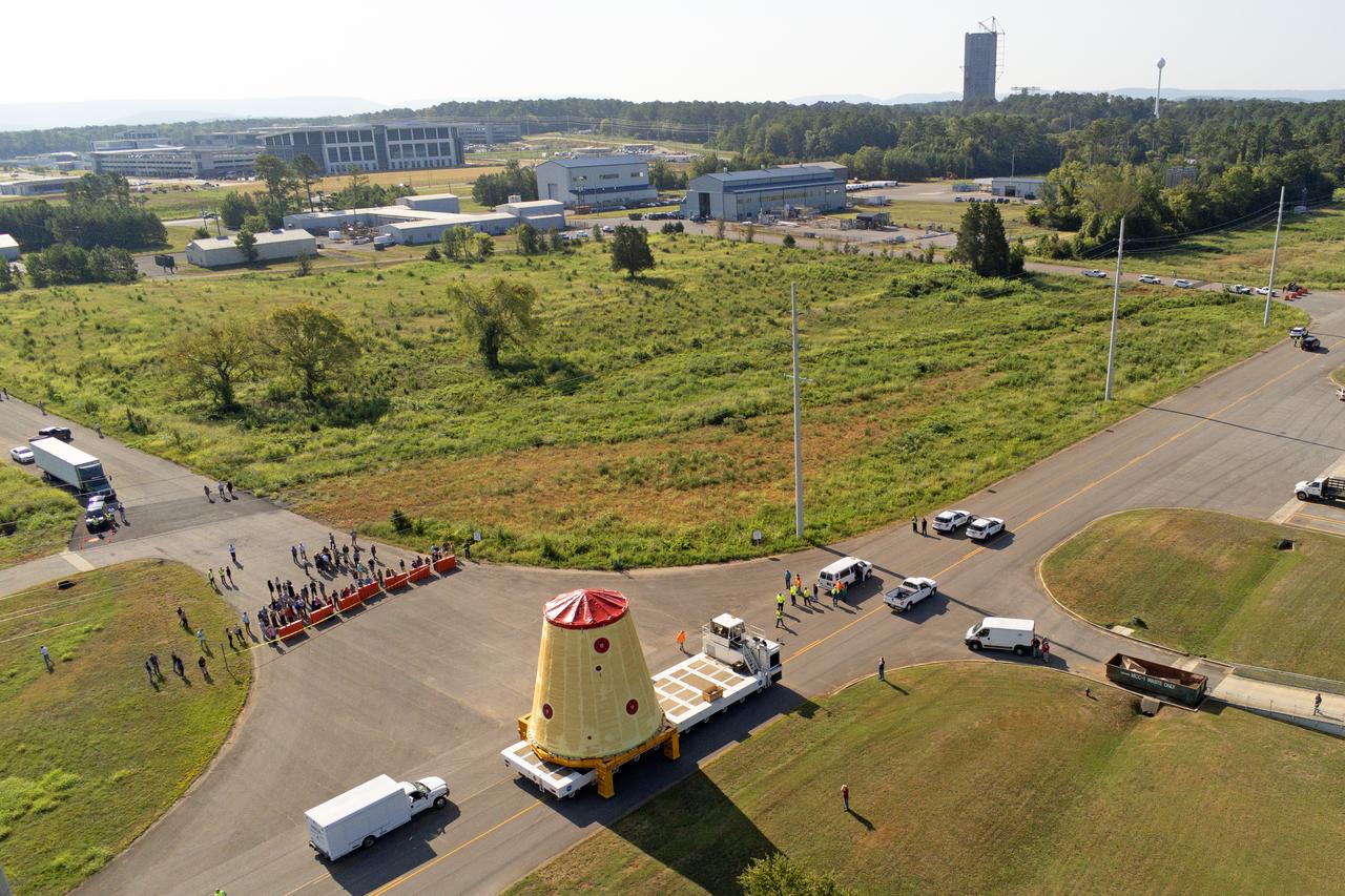
NASA rolled out a key piece of space flight hardware for the SLS (Space Launch System) rocket for the first crewed mission of NASA’s Artemis campaign from Marshall Space Flight Center in Huntsville, Alabama, on Wednesday, Aug. 21 for shipment to the agency’s spaceport in Florida. The cone-shaped launch vehicle stage adapter connects the rocket’s core stage to the upper stage and helps protect the upper stage’s engine that will help propel the Artemis II test flight around the Moon, slated for 2025. Manufactured by prime contractor Teledyne Brown Engineering and the Jacobs Space Exploration Group’s ESSCA (Engineering Services and Science Capability Augmentation) contract using NASA Marshall’s self-reacting friction-stir robotic and vertical weld tools. Crews moved the adapter out of NASA Marshall’s Building 4708 to the agency’s Pegasus barge Aug. 21. The barge will ferry the adapter first to NASA’s Michoud Assembly Facility in New Orleans, where crews will pick up additional SLS hardware for future Artemis missions, before traveling to NASA Kennedy. Once in Florida, the adapter will join the recently delivered core stage. There, teams with NASA’s Exploration Ground Systems will prepare the adapter for stacking and launch.
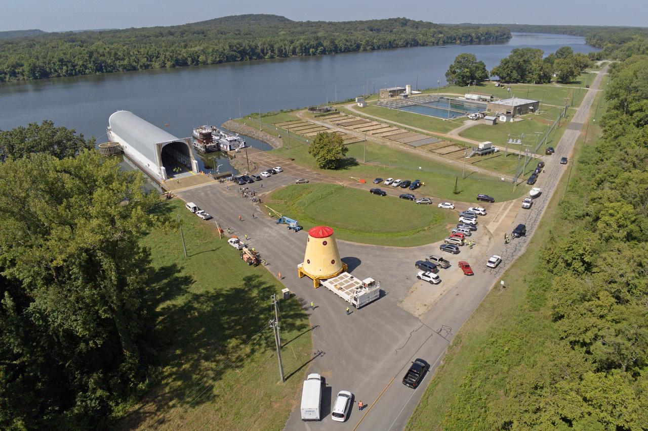
NASA rolled out a key piece of space flight hardware for the SLS (Space Launch System) rocket for the first crewed mission of NASA’s Artemis campaign from Marshall Space Flight Center in Huntsville, Alabama, on Wednesday, Aug. 21 for shipment to the agency’s spaceport in Florida. The cone-shaped launch vehicle stage adapter connects the rocket’s core stage to the upper stage and helps protect the upper stage’s engine that will help propel the Artemis II test flight around the Moon, slated for 2025. Manufactured by prime contractor Teledyne Brown Engineering and the Jacobs Space Exploration Group’s ESSCA (Engineering Services and Science Capability Augmentation) contract using NASA Marshall’s self-reacting friction-stir robotic and vertical weld tools. Crews moved the adapter out of NASA Marshall’s Building 4708 to the agency’s Pegasus barge Aug. 21. The barge will ferry the adapter first to NASA’s Michoud Assembly Facility in New Orleans, where crews will pick up additional SLS hardware for future Artemis missions, before traveling to NASA Kennedy. Once in Florida, the adapter will join the recently delivered core stage. There, teams with NASA’s Exploration Ground Systems will prepare the adapter for stacking and launch.
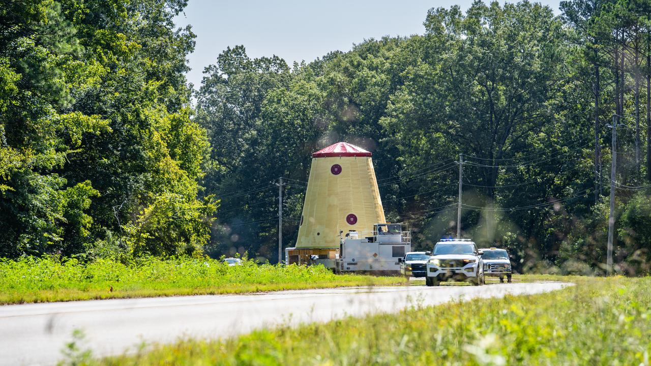
NASA rolled out a key piece of space flight hardware for the SLS (Space Launch System) rocket for the first crewed mission of NASA’s Artemis campaign from Marshall Space Flight Center in Huntsville, Alabama, on Wednesday, Aug. 21 for shipment to the agency’s spaceport in Florida. The cone-shaped launch vehicle stage adapter connects the rocket’s core stage to the upper stage and helps protect the upper stage’s engine that will help propel the Artemis II test flight around the Moon, slated for 2025. Manufactured by prime contractor Teledyne Brown Engineering and the Jacobs Space Exploration Group’s ESSCA (Engineering Services and Science Capability Augmentation) contract using NASA Marshall’s self-reacting friction-stir robotic and vertical weld tools. Crews moved the adapter out of NASA Marshall’s Building 4708 to the agency’s Pegasus barge Aug. 21. The barge will ferry the adapter first to NASA’s Michoud Assembly Facility in New Orleans, where crews will pick up additional SLS hardware for future Artemis missions, before traveling to NASA Kennedy. Once in Florida, the adapter will join the recently delivered core stage. There, teams with NASA’s Exploration Ground Systems will prepare the adapter for stacking and launch

NASA rolled out a key piece of space flight hardware for the SLS (Space Launch System) rocket for the first crewed mission of NASA’s Artemis campaign from Marshall Space Flight Center in Huntsville, Alabama, on Wednesday, Aug. 21 for shipment to the agency’s spaceport in Florida. The cone-shaped launch vehicle stage adapter connects the rocket’s core stage to the upper stage and helps protect the upper stage’s engine that will help propel the Artemis II test flight around the Moon, slated for 2025. Manufactured by prime contractor Teledyne Brown Engineering and the Jacobs Space Exploration Group’s ESSCA (Engineering Services and Science Capability Augmentation) contract using NASA Marshall’s self-reacting friction-stir robotic and vertical weld tools. Crews moved the adapter out of NASA Marshall’s Building 4708 to the agency’s Pegasus barge Aug. 21. The barge will ferry the adapter first to NASA’s Michoud Assembly Facility in New Orleans, where crews will pick up additional SLS hardware for future Artemis missions, before traveling to NASA Kennedy. Once in Florida, the adapter will join the recently delivered core stage. There, teams with NASA’s Exploration Ground Systems will prepare the adapter for stacking and launch.
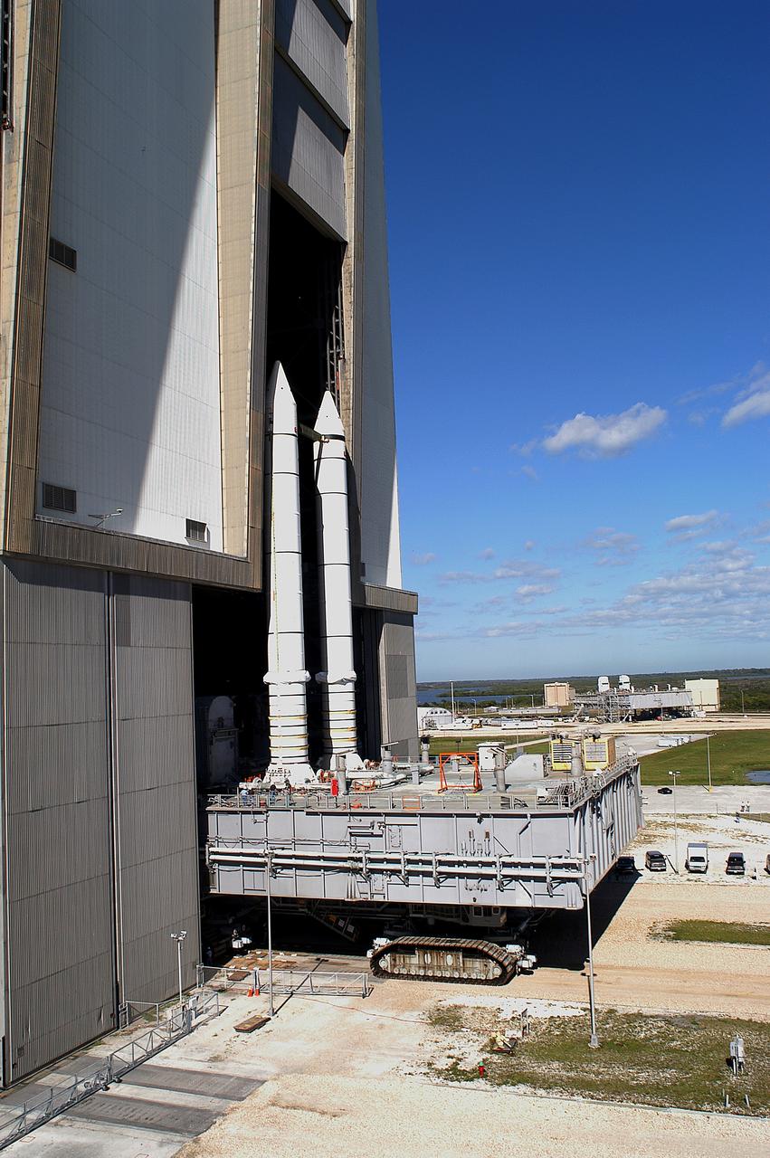
KENNEDY SPACE CENTER, FLA. - Mobile Launcher Platform (MLP) number 3 and a set of twin solid rocket boosters, atop the crawler-transporter, crawl out of the Vehicle Assembly Building (VAB) in support of the second engineering analysis vibration test on the crawler and MLP. In the background is another MLP. The crawler is moving at various speeds up to 1 mph in an effort to achieve vibration data gathering goals as it leaves the VAB, travels toward Launch Pad 39A and then returns. The boosters are braced at the top for stability. The primary purpose of these rollout tests is to gather data to develop future maintenance requirements on the transport equipment and the flight hardware. Various parts of the MLP and crawler transporter have been instrumented with vibration data collection equipment.
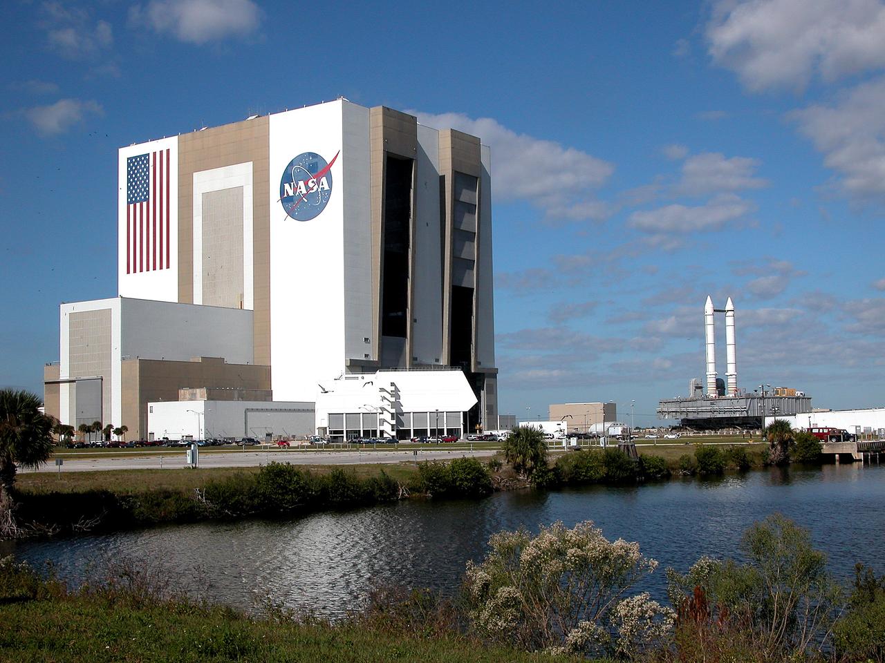
KENNEDY SPACE CENTER, FLA. - Seen across the water of the Launch Complex 39 turn basin, a crawler-transporter, carrying Mobile Launcher Platform (MLP) number 3 with a set of twin solid rocket boosters bolted atop, crawls out of the 525-foot-tall Vehicle Assembly Building during the second engineering analysis vibration test on the crawler and MLP. The crawler is moving at various speeds up to 1 mph in an effort to achieve vibration data gathering goals as it leaves the VAB, travels toward Launch Pad 39A and then returns. The boosters are braced at the top for stability. The primary purpose of these rollout tests is to gather data to develop future maintenance requirements on the transport equipment and the flight hardware. Various parts of the MLP and crawler transporter have been instrumented with vibration data collection equipment.
Tree clearing for the site of the new A-3 Test Stand at Stennis Space center began June 13. NASA's first new large rocket engine test stand to be built since the site's inception, A-3 construction begins a historic era for America's largest rocket engine test complex. The 300-foot-tall structure is scheduled for completion in August 2010. A-3 will perform altitude tests on the Constellation's J-2X engine that will power the upper stage of the Ares I crew launch vehicle and earth departure stage of the Ares V cargo launch vehicle. The Constellation Program, NASA's plan for carrying out the nation's Vision for Space Exploration, will return humans to the moon and eventually carry them to Mars and beyond.
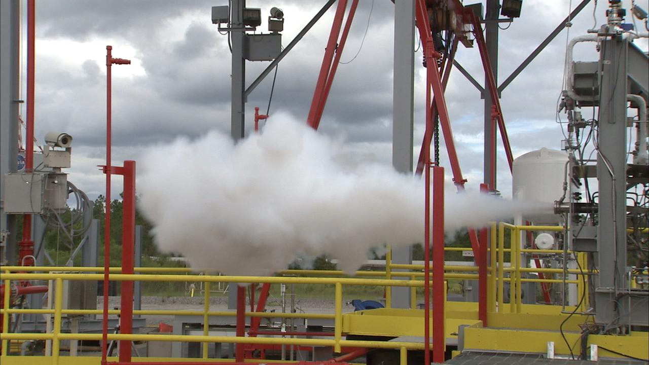
Tests begun at Stennis Space Center's E Complex Sept. 13 evaluated a liquid oxygen lead for engine start performance, part of the A-3 Test Facility Subscale Diffuser Risk Mitigation Project at SSC's E-3 Test Facility. Phase 1 of the subscale diffuser project, completed Sept. 24, was a series of 18 hot-fire tests using a 1,000-pound liquid oxygen and gaseous hydrogen thruster to verify maximum duration and repeatability for steam generation supporting the A-3 Test Stand project. The thruster is a stand-in for NASA's developing J-2X engine, to validate a 6 percent scale version of A-3's exhaust diffuser. Testing the J-2X at altitude conditions requires an enormous diffuser. Engineers will generate nearly 4,600 pounds per second of steam to reduce pressure inside A-3's test cell to simulate altitude conditions. A-3's exhaust diffuser has to be able to withstand regulated pressure, temperatures and the safe discharge of the steam produced during those tests. Before the real thing is built, engineers hope to work out any issues on the miniature version. Phase 2 testing is scheduled to begin this month.
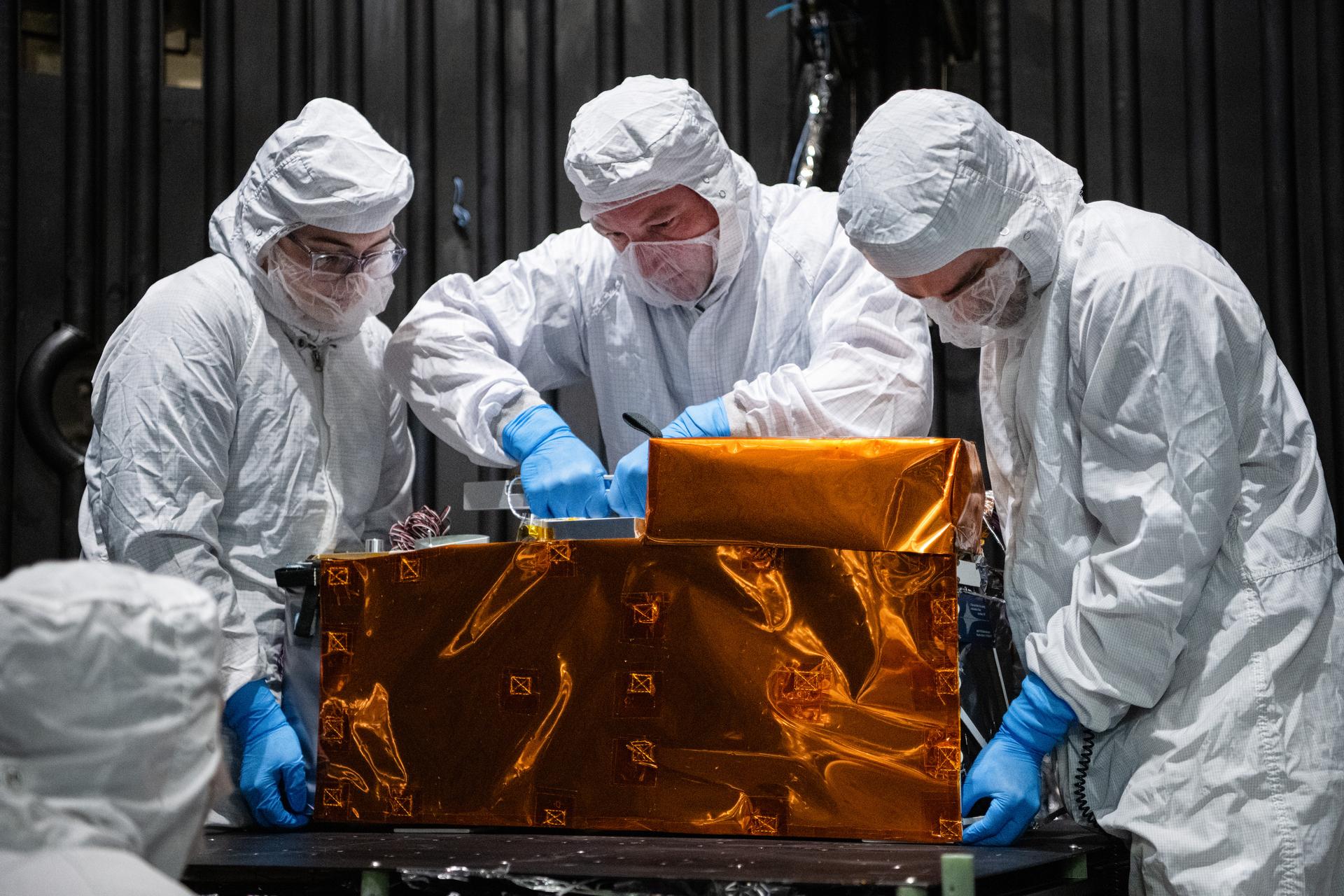
From left, mechanical engineer Gabrielle Ludwig, technician Alex Schaeffer, and mechanical engineer Mitchell Hamann install the Lunar Environment Monitoring Station (LEMS) instrument onto a test plate in a thermal vacuum chamber at Goddard Space Flight Center, Greenbelt Md., March 30, 2026. LEMS is a compact, autonomous, and self-sustaining seismometer suite designed to carry out continuous, long-term, monitoring of the lunar seismic environment at the South Polar region. Photo Credit: NASA/Denny Henry