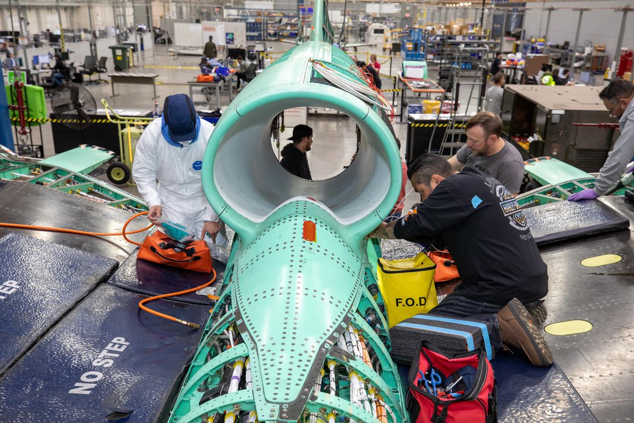
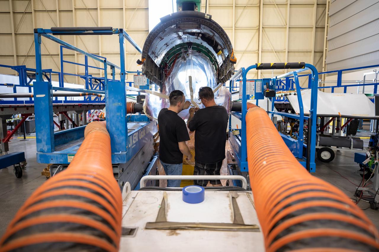
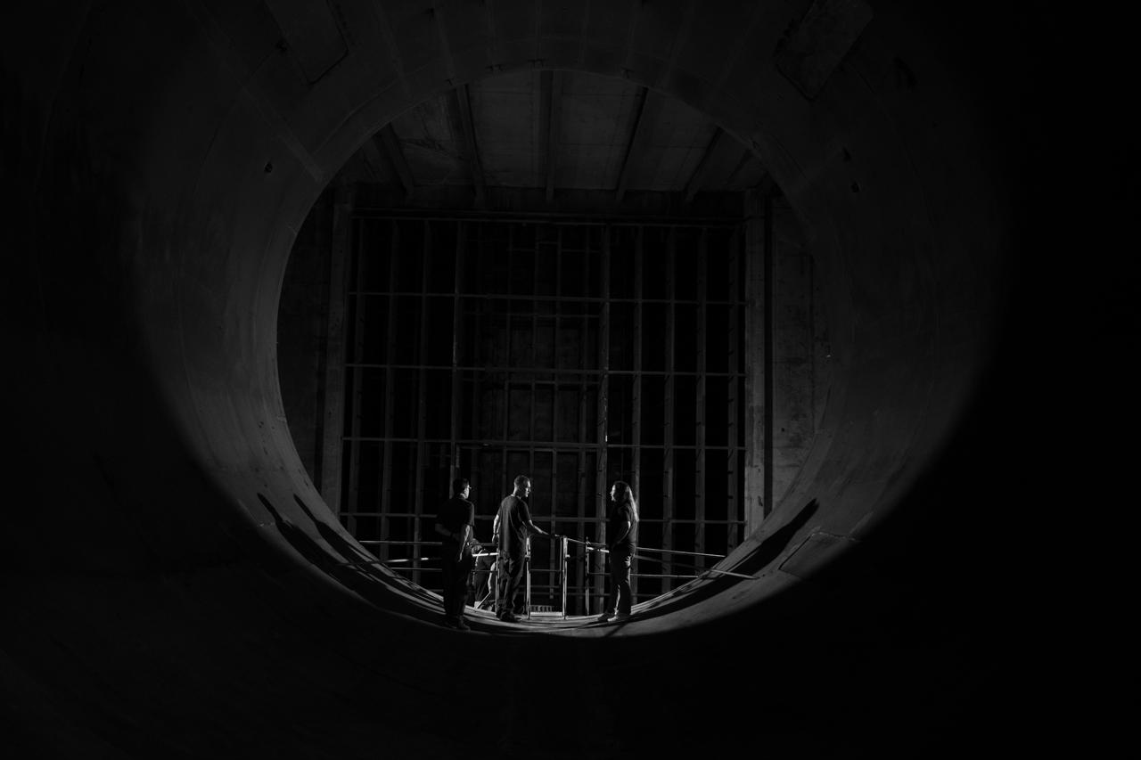
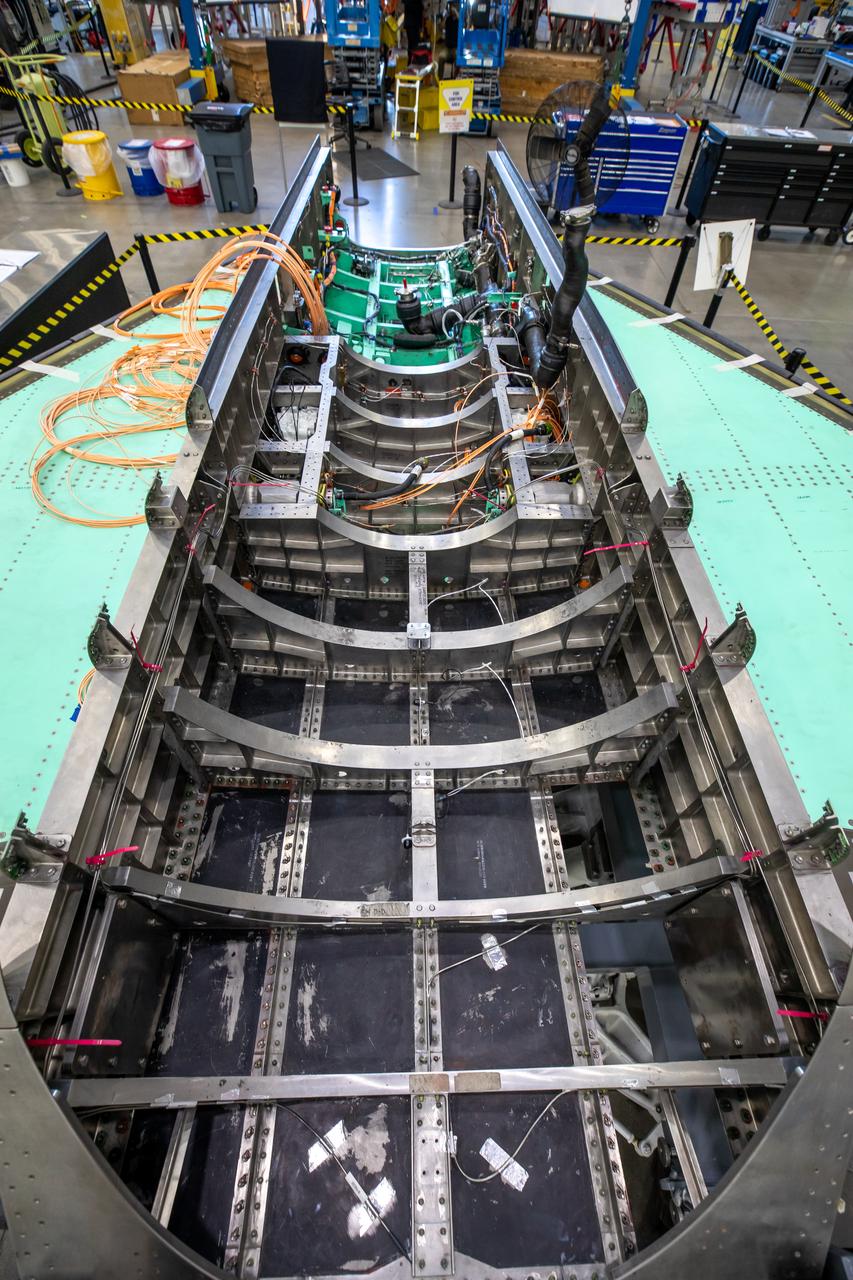
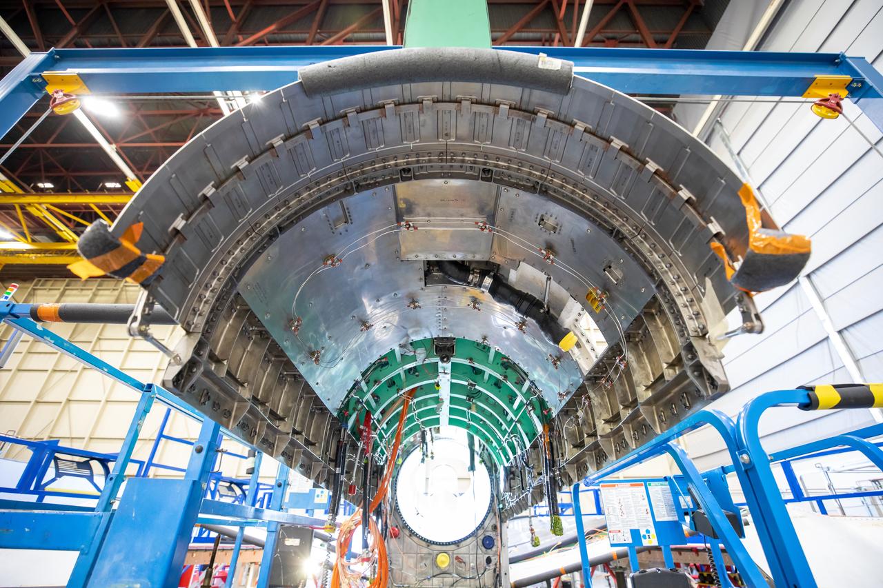
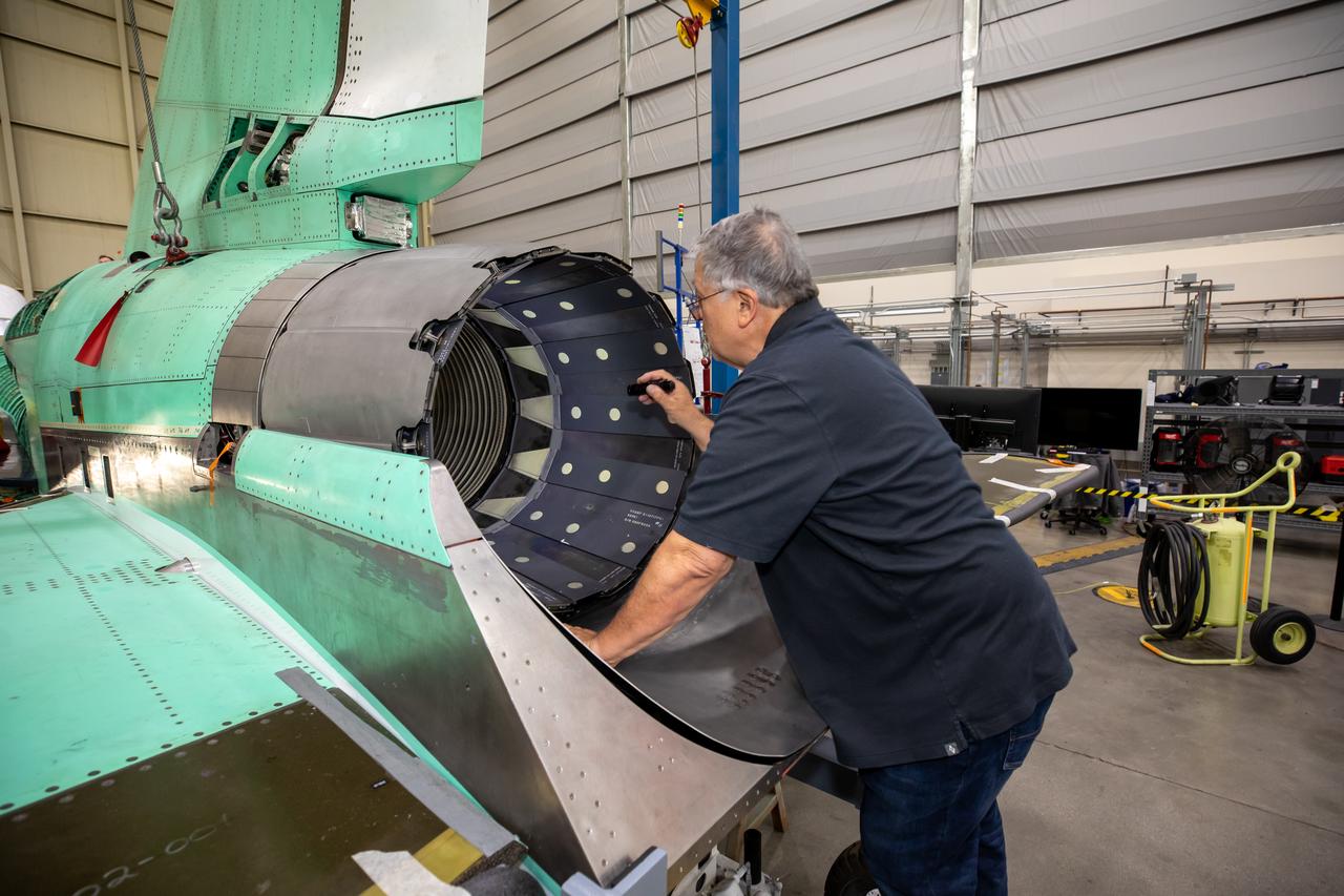
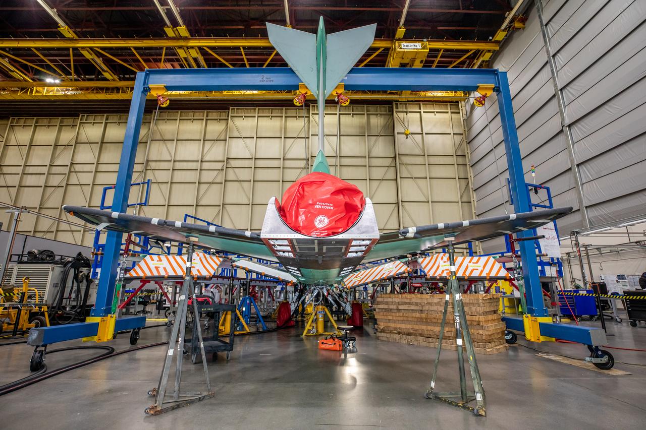
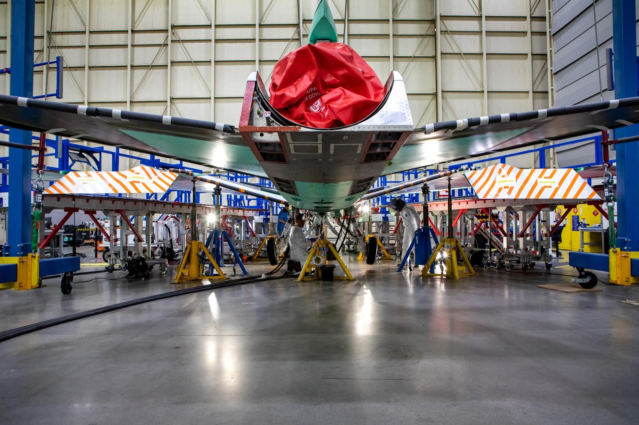
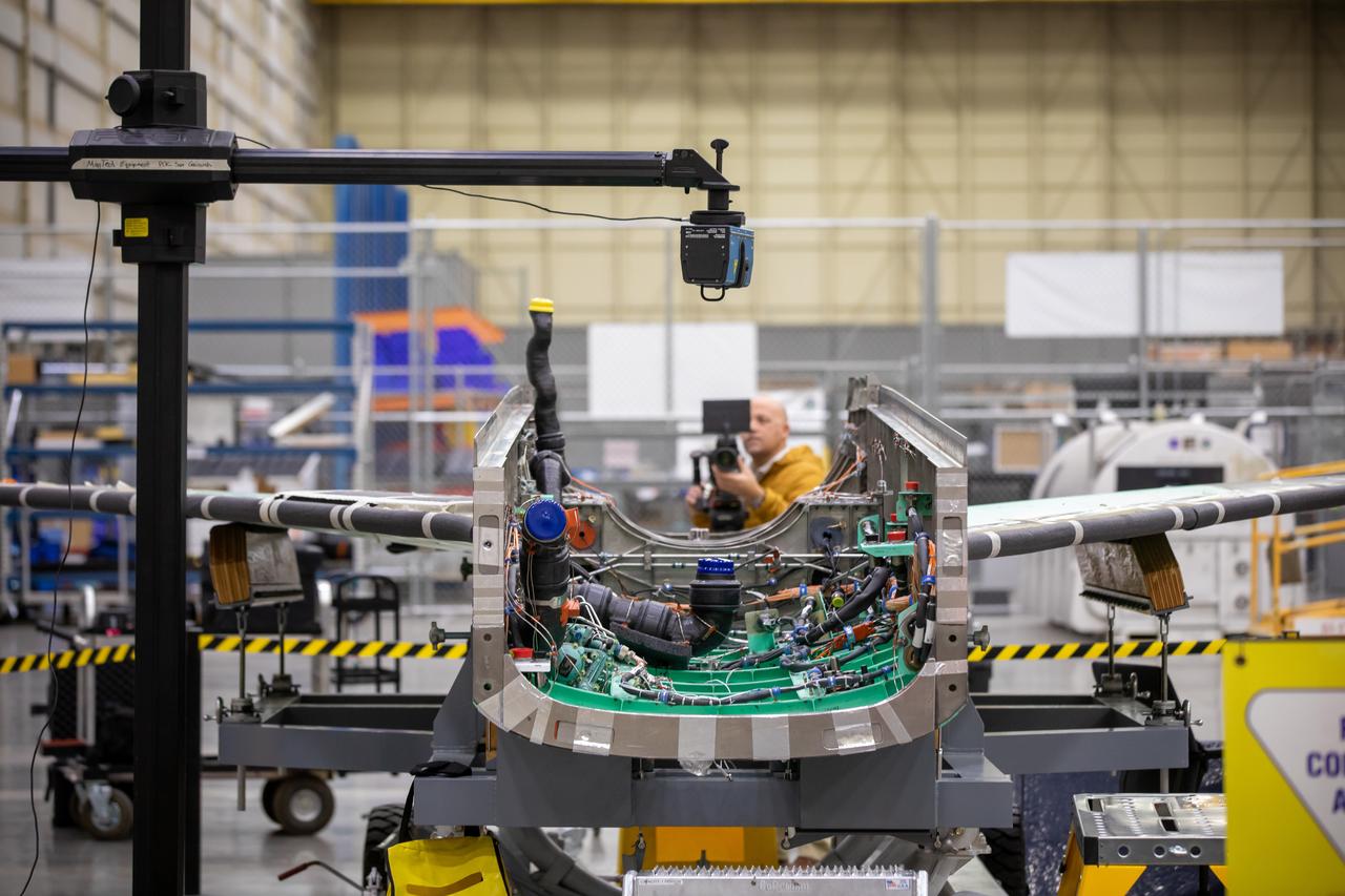
The X-59 team working on the aircraft’s wiring around the engine inlet prior to the engine being installed. Once complete, the X-59 is designed to fly supersonic while reducing the loud sonic boom. The Quesst mission could help change the rules for commercial supersonic air travel over land.
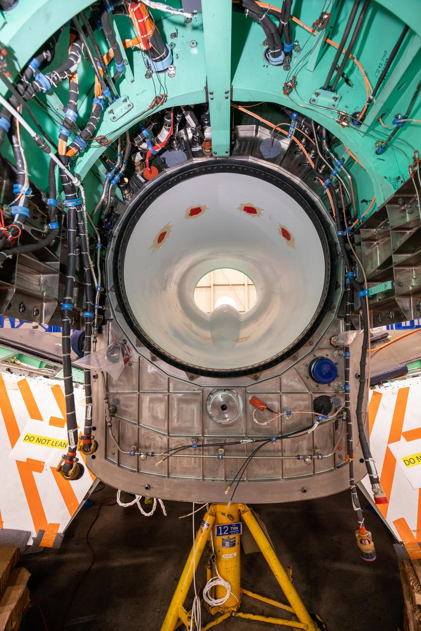
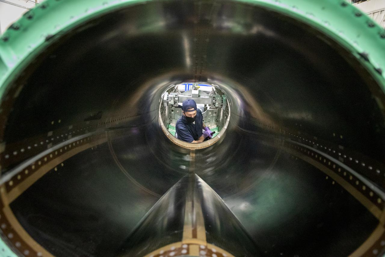
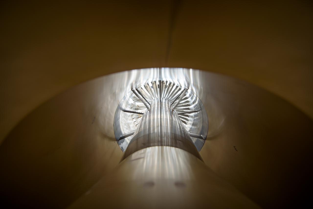
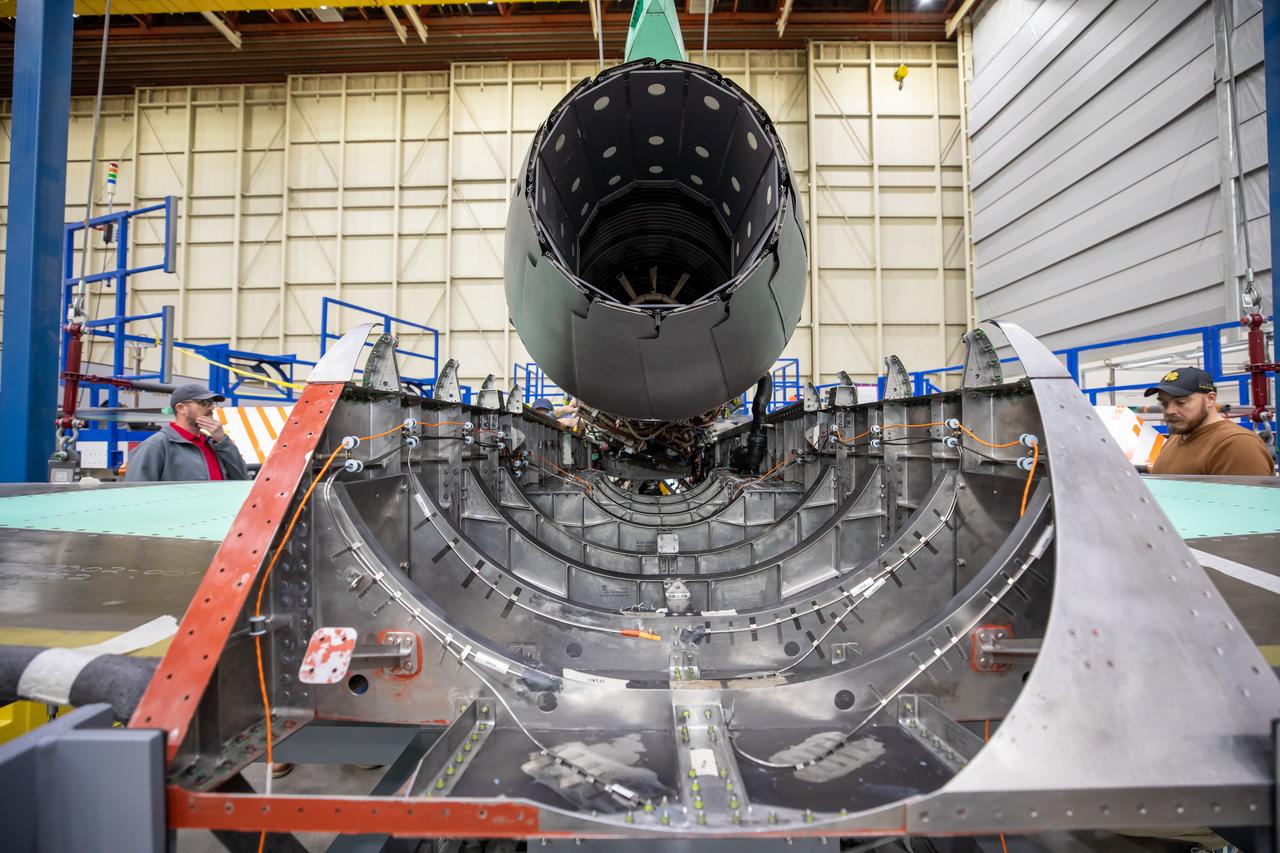
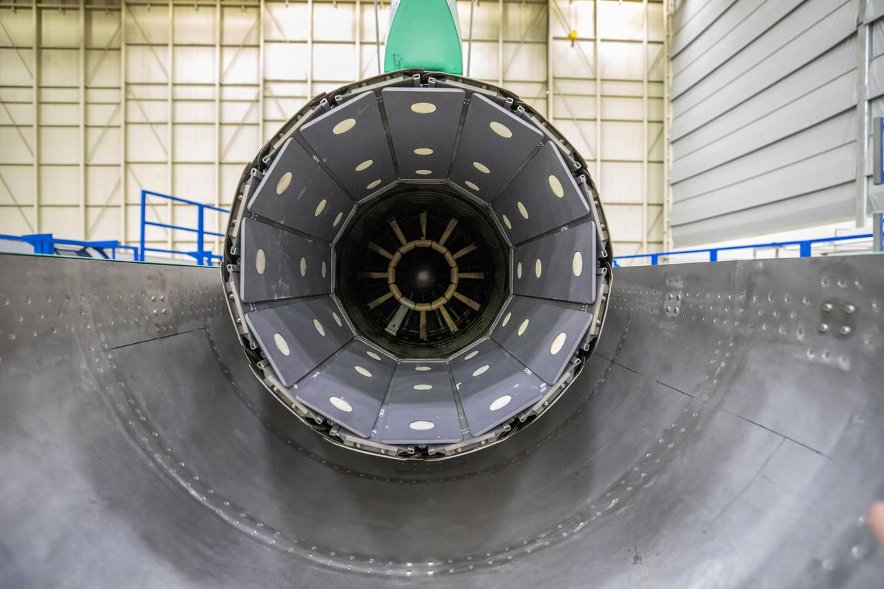
This image shows the X-59’s engine inlet from the aft view, which is the rear of the airplane, looking forward. Once the aircraft and ground testing are complete, the X-59 will undergo flight testing, which will demonstrate the plane’s ability to fly supersonic - faster than the speed of sound - while reducing the loud sonic boom. This could enable commercial supersonic air travel over land again.
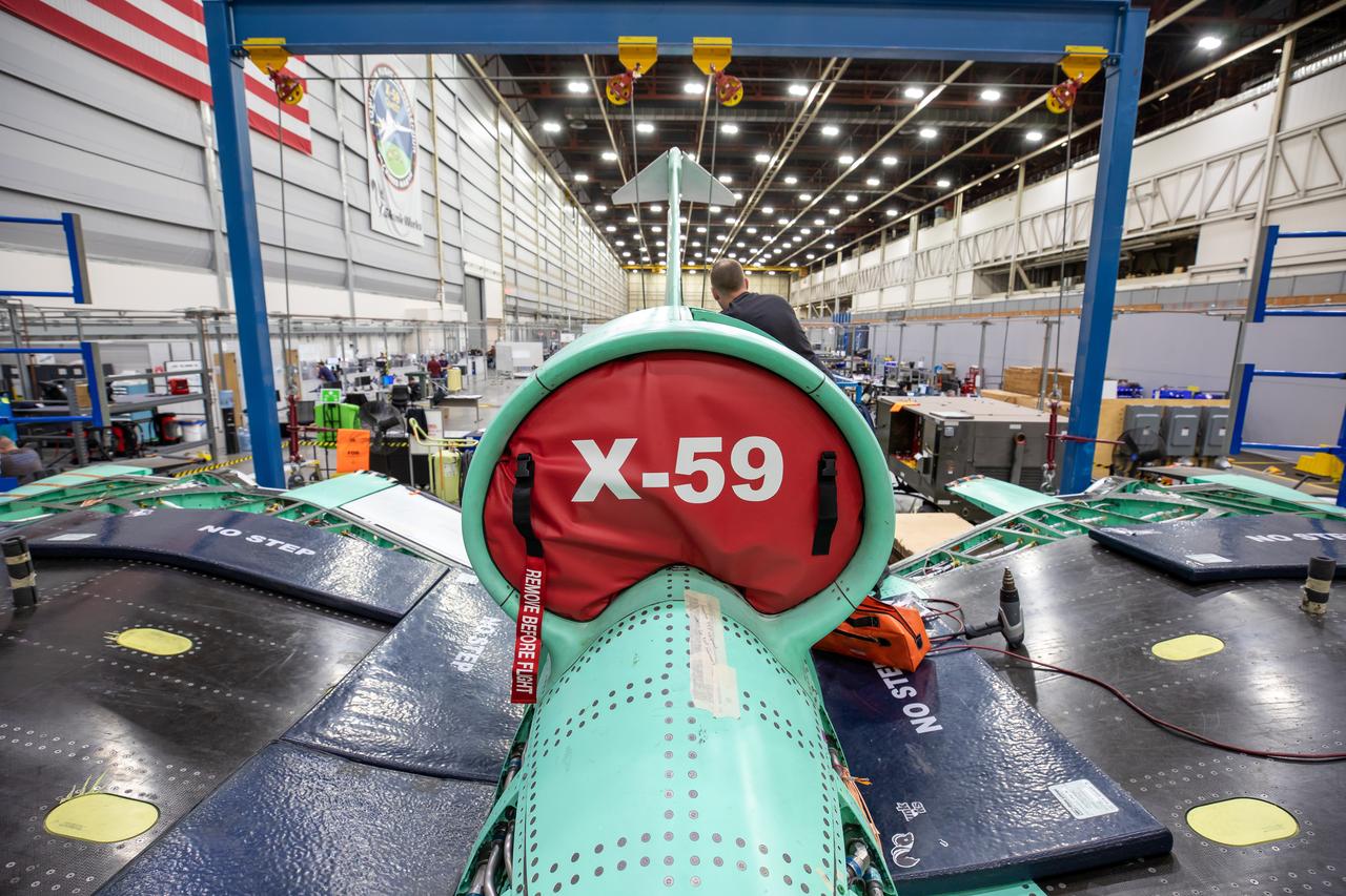
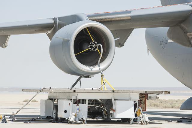
This is an image of the X-59 inlet with a safety covering. The inlet’s purpose is to adjust air speeds before they pass through the aircraft’s engine. The purpose of the covering is to protect the inlet and engine from foreign objects.
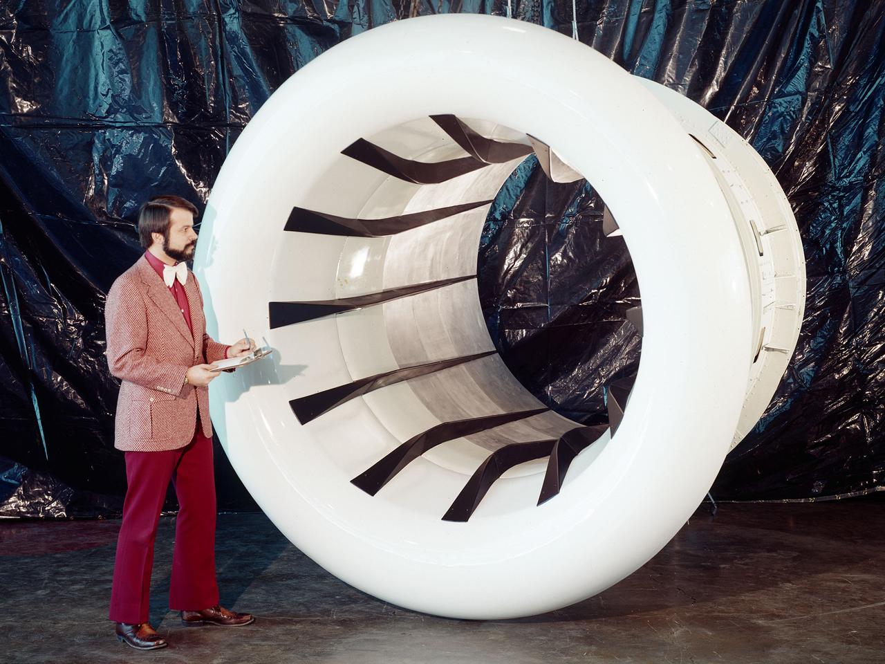
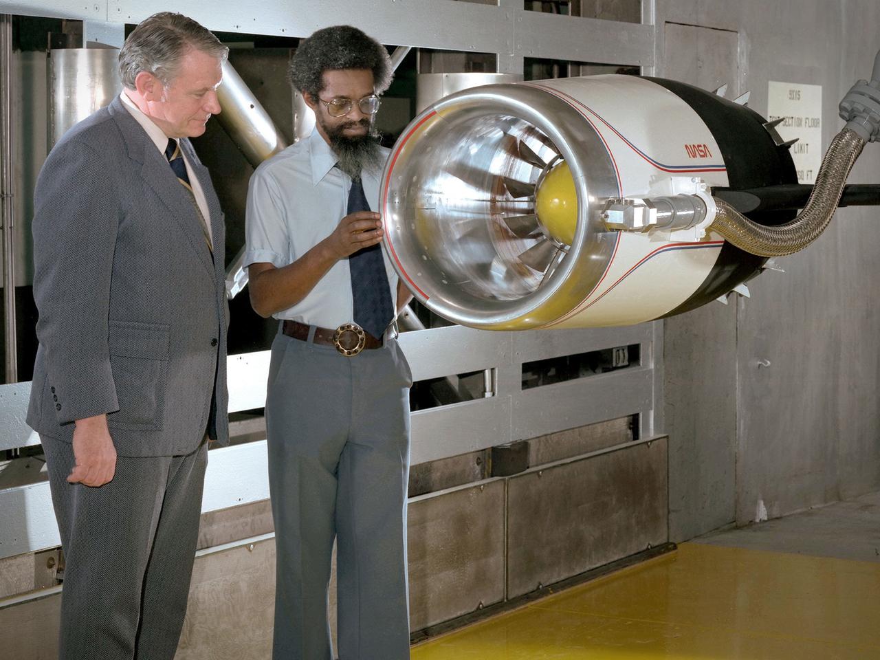
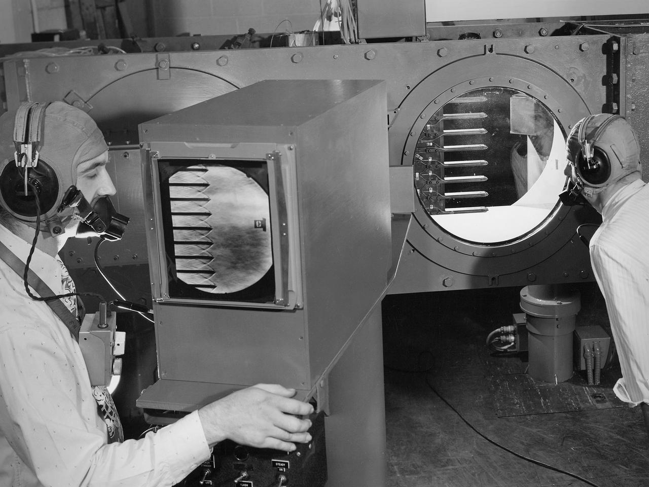
Brent Miller, of the V/STOL and Noise Division at the National Aeronautics and Space Administration (NASA) Lewis Research Center, poses with a sonic inlet for the NASA Quiet Engine Program. NASA Lewis had first investigated methods for reducing aircraft engine noise in the mid-1950s. Those efforts were resurrected and expanded in the late 1960s. The researchers found that the use of a sonic, or high-throat-Mach-number, inlet was effective at reducing the noise from the engine inlet. The device accelerated the inlet air to near-sonic speeds which kept the forward moving sound waves away from the inlet. The device also deflected the sound waves into the wall to further reduce the noise. NASA Lewis researchers tested models of the sonic inlet in their 9- by 15-Foot Low Speed Wind Tunnel. They found that the general level of aerodynamic performance was good. The tests during simulated takeoff and landing conditions demonstrated the sonic inlet’s ability to provide good aerodynamic and acoustic performance The researchers then successfully tested two full-scale sonic inlet designs, one from Pratt and Whitney and one from General Electric, with fans. A full-scale engine was installed on a thrust stand to determine the sonic inlet’s effect on the engine’s performance. The amount of noise reduction increased as the inlet flow velocity increased, but the full-scale tests did not produce as great a decrease in noise as the earlier small-scale tests.
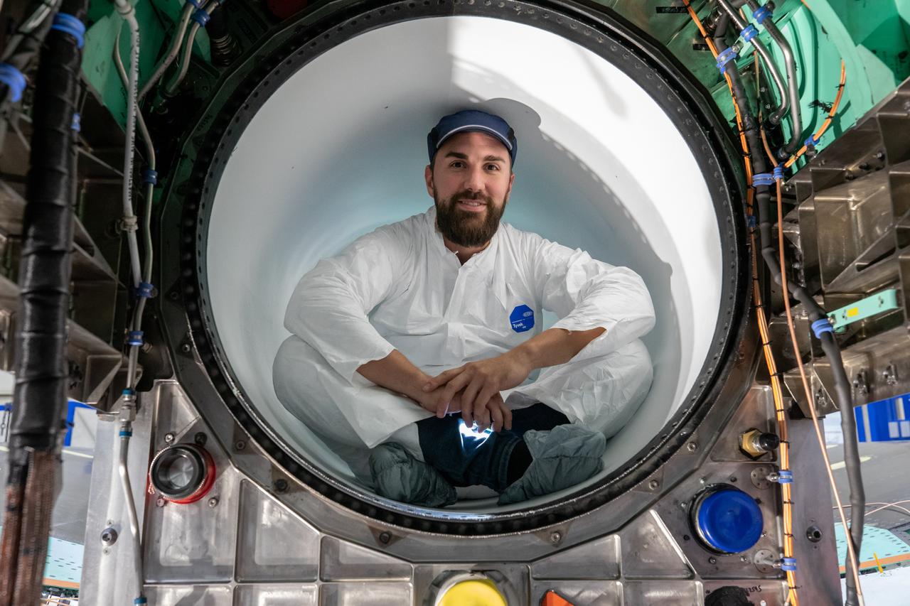
A Lockheed Martin Skunk Works technician takes a break for a photo. Note that the technician is wearing protective clean gear while sitting inside the X-59 engine inlet. Wearing this gear reduces the chance of any foreign objects from damaging the engine inlet.
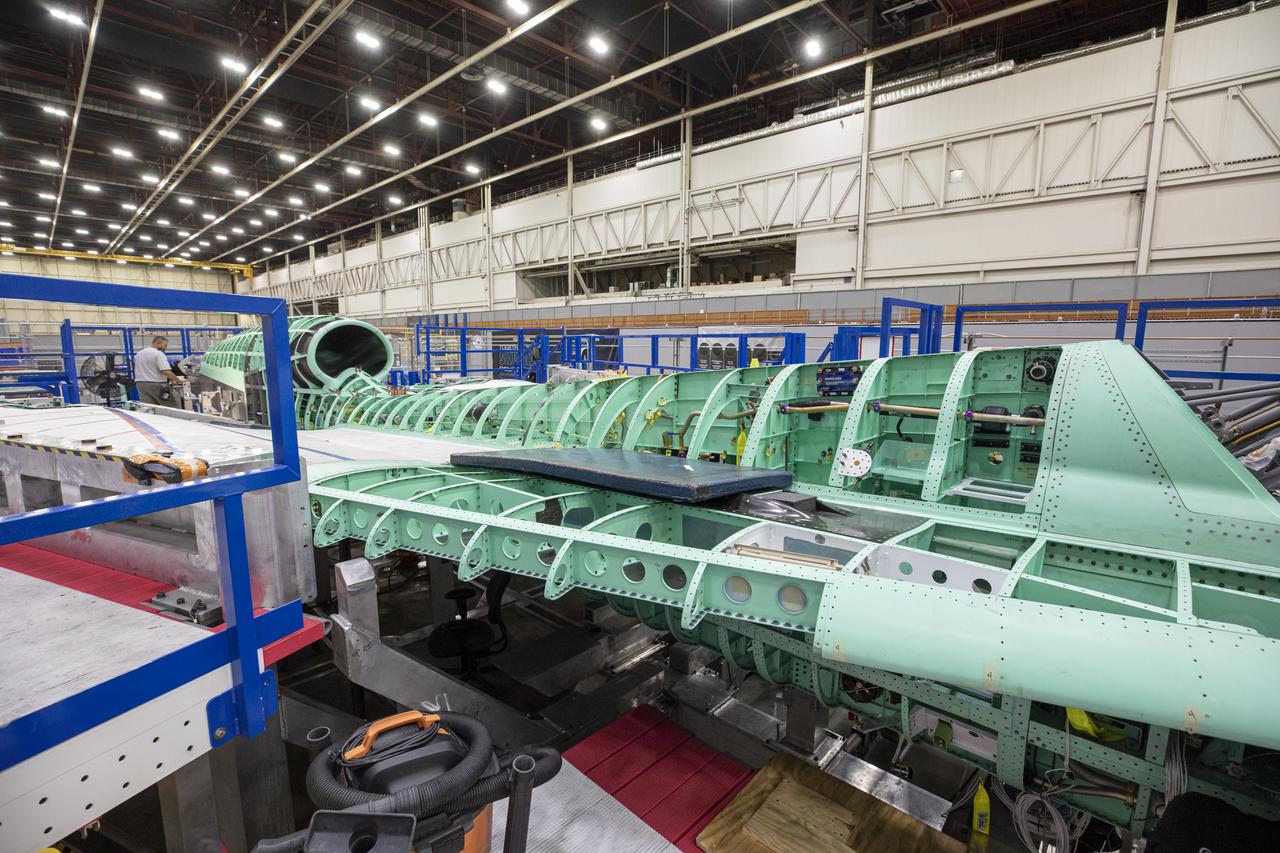
Pictured here is a side view of the X-59 spine and engine inlet during assembly. Lockheed Martin Photography By Garry Tice 1011 Lockheed Way, Palmdale, Ca. 93599 Event: SEG 210 Forebody, SEG 430 Spine, SEG 500 Empennage Date: 6/08/2021
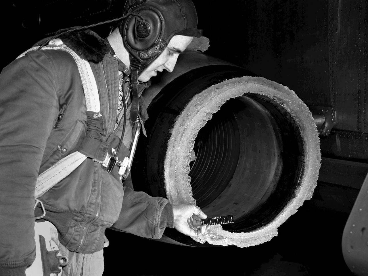
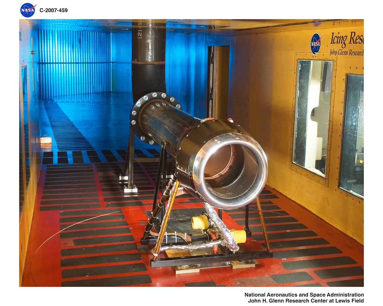
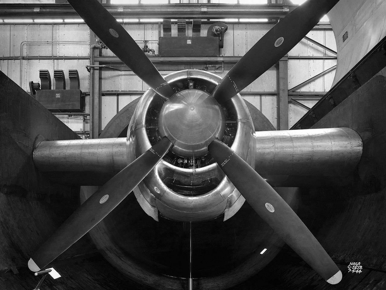
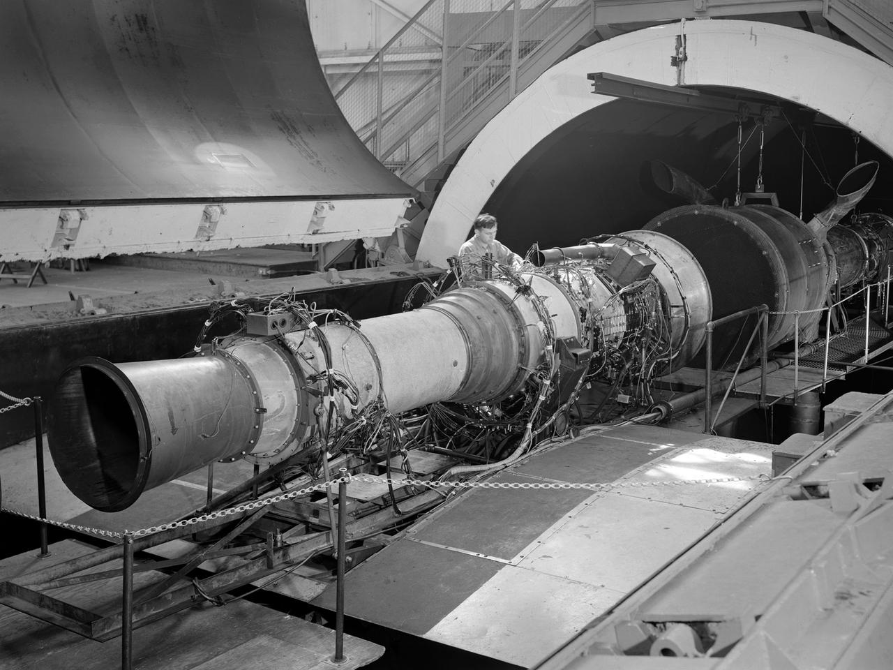
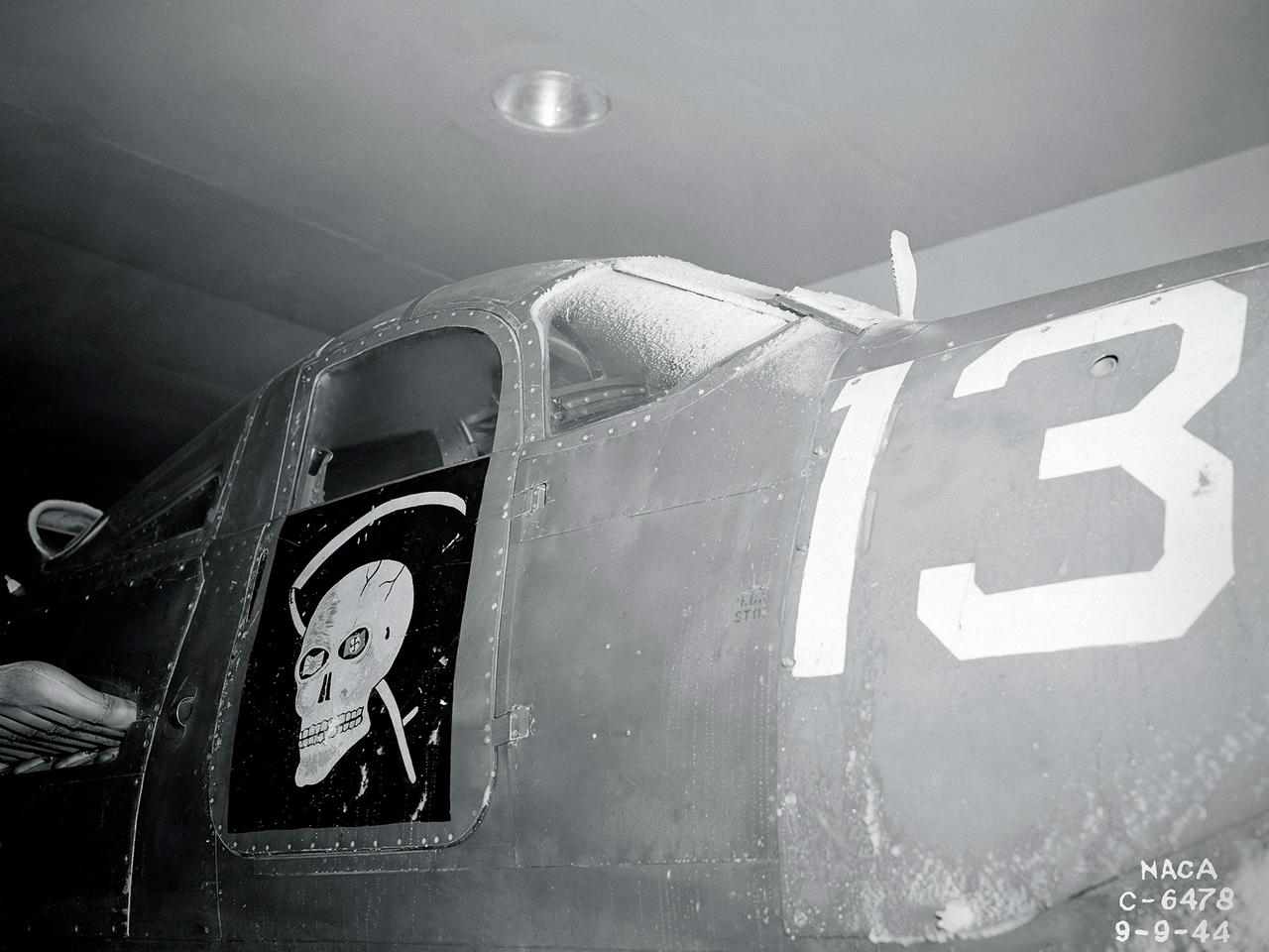
The National Advisory Committee for Aeronautics (NACA) Lewis Flight Propulsion Laboratory conducted an extensive icing research program in the late 1940s that included studies in the Icing Research Tunnel and using specially modified aircraft. One facet of this program was the investigation of the effects of icing on turbojets. Although jet engines allowed aircraft to pass through inclement weather at high rates of speed, ice accumulation was still a concern. The NACA’s B-24M Liberator was initially reconfigured with a General Electric I-16 engine installed in the aircraft’s waist compartment with an air scoop and spray nozzles to produce the artificial icing conditions. The centrifugal engine appeared nearly impervious to the effects of icing. Axial-flow jet engines, however, were much more susceptible to icing damage. The inlet guide vanes were particularly vulnerable, but the cowling’s leading edge, the main bearing supports, and accessory housing could also ice up. If pieces of ice reached the engine’s internal components, the compressor blades could be damaged. To study this phenomenon, a Westinghouse 24C turbojet, seen in this photograph, was installed under the B-24M’s right wing. In January 1948 flight tests of the 24C in icing conditions began. Despite ice buildup into the second stage of the compressor, the engine was able to operate at takeoff speeds. Researchers found the ice on the inlet vanes resulted in half of the engine’s decreased performance.
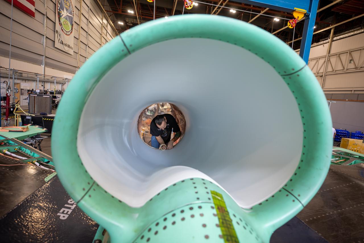
This is an up-close view of the X-59’s engine inlet – fresh after being painted. The 13-foot F414-GE-100 engine will be placed inside the inlet bringing the X-59 aircraft one step closer to completion. Once fully assembled, the X-59 aircraft will begin flight operations, working toward demonstration of the ability to fly supersonic while reducing the loud sonic boom to a quiet sonic thump, helping to enable commercial supersonic air travel over land.
The volcanic ash distribution spider, shown here in the inlet of the engine while running, was used to send the ultra-fine particles of ash through the engine.
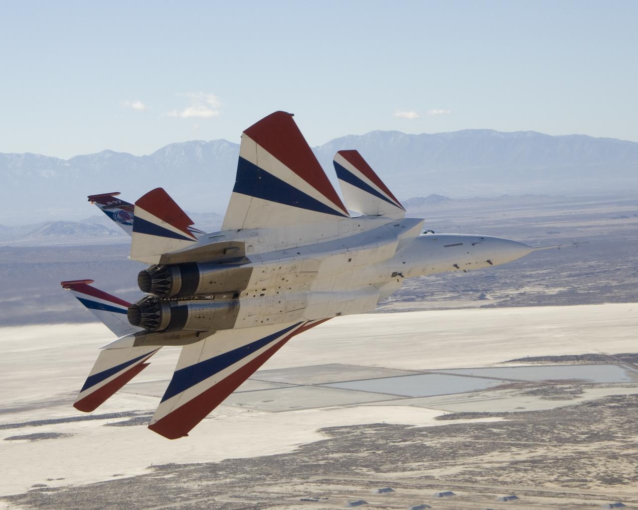
Two small Range Safety System antennas are located just behind the engine inlets of NASA's NF-15B research aircraft as it banks away from the chase plane.
A technician is working on the engine inlet of NASA’s X-59 Quiet Supersonic Technology (QueSST) aircraft at Lockheed Martin’s Skunk Works facility in Palmdale, California.

The NASA Dryden 747 Shuttle Carrier Aircraft crew poses in an engine inlet; Standing L to R - aircraft mechanic John Goleno and SCA Team Leader Pete Seidl; Kneeling L to R - aircraft mechanics Todd Weston and Arvid Knutson, and avionics technician Jim Bedard NASA uses two modified Boeing 747 jetliners, originally manufactured for commercial use, as Space Shuttle Carrier Aircraft (SCA). One is a 747-100 model, while the other is designated a 747-100SR (short range). The two aircraft are identical in appearance and in their performance as Shuttle Carrier Aircraft. The 747 series of aircraft are four-engine intercontinental-range swept-wing "jumbo jets" that entered commercial service in 1969. The SCAs are used to ferry space shuttle orbiters from landing sites back to the launch complex at the Kennedy Space Center, and also to and from other locations too distant for the orbiters to be delivered by ground transportation. The orbiters are placed atop the SCAs by Mate-Demate Devices, large gantry-like structures which hoist the orbiters off the ground for post-flight servicing, and then mate them with the SCAs for ferry flights.
This image shows the extensive ventilation system that has been placed adjacent to the X-59 during the recent painting of the aircraft’s engine inlet. Once the aircraft build and ground testing are complete, the X-59 airplane will begin flight testing, working towards demonstrating the ability to fly supersonic while reducing the loud sonic boom to a quiet sonic thump and help enable commercial supersonic air travel over land.
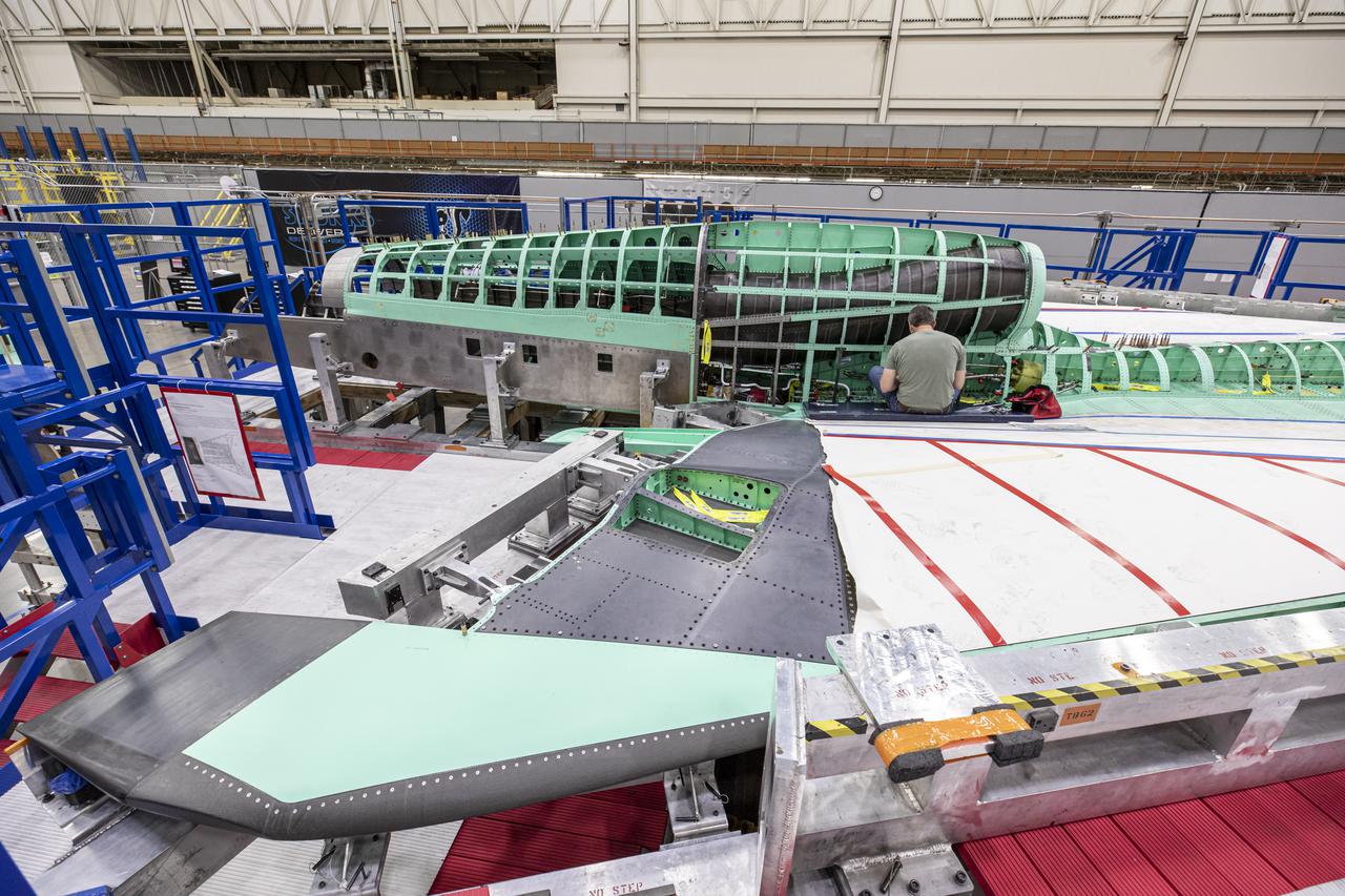
Here is a wide shot of the wing, engine and engine inlet area of NASA’s X-59 Quiet SuperSonic Technology or QueSST aircraft. The aircraft, under construction at Lockheed Martin Skunk Works in Palmdale, California, will fly to demonstrate the ability to fly supersonic while reducing the loud sonic boom to a quiet sonic thump. Lockheed Martin Photography By Garry Tice 1011 Lockheed Way, Palmdale, Ca. 93599 Event: SEG 400 Main Wing Assembly, SEG 430 Spine, SEG 500 Empennage Date: 4/28/2021

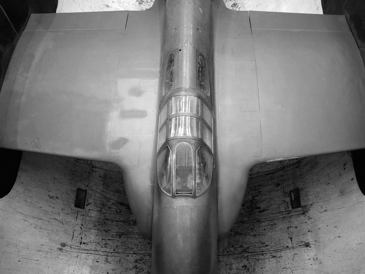
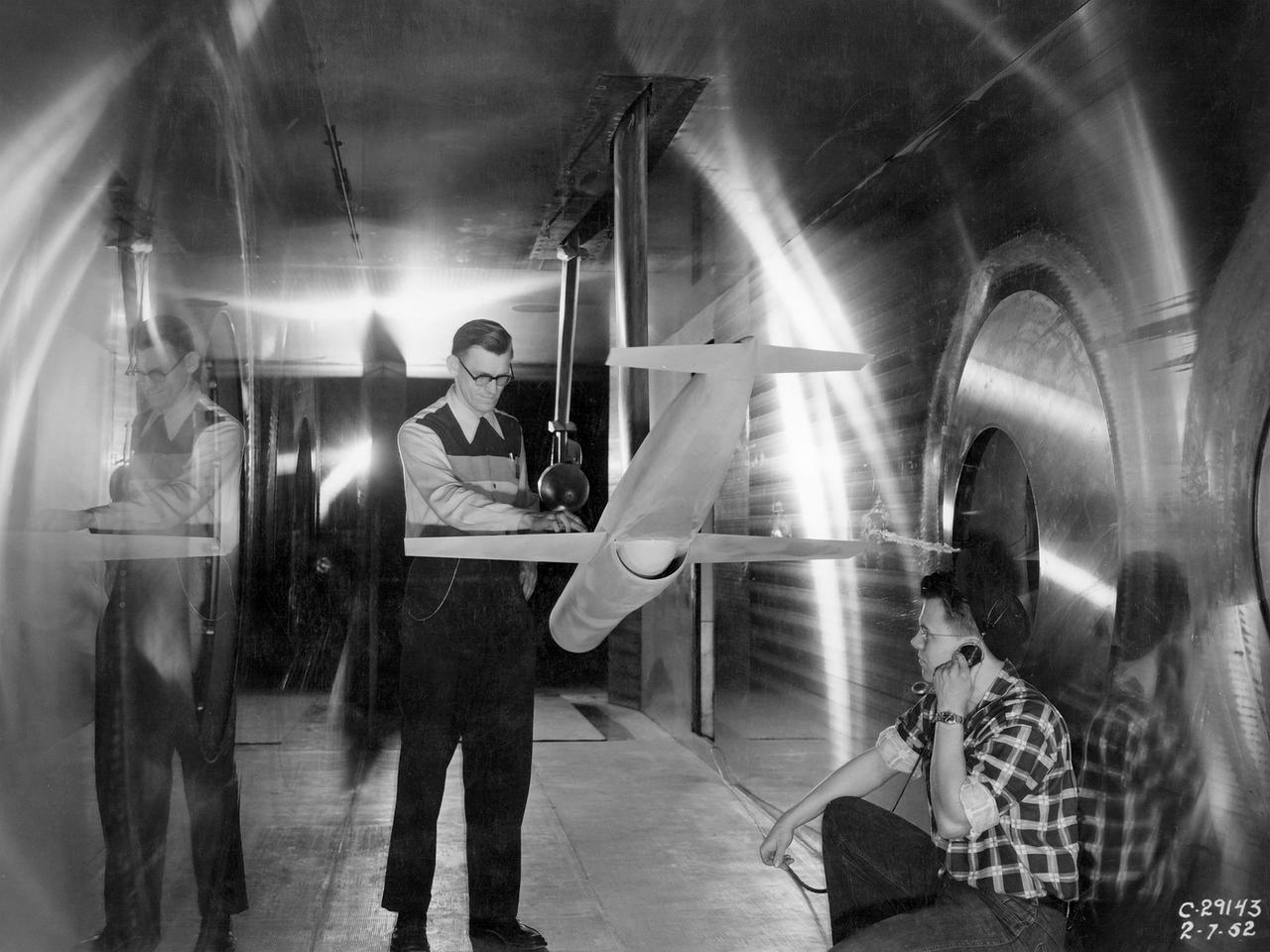
Flight evaluation and comparison of a NACA submerged inlet and a scoop inlet on the North American YF-93A (AF48-317 NACA-139). The YF-93A's were the first aircraft to use flush NACA engine inlets. aircraft to use flush NACA engine inlets. Note: Used in publication in Flight Research at Ames; 57 Years of Development and Validation of Aeronautical Technology NASA SP-1998-3300 and Memoirs of a Flight Test Engineer NASA SP-2001-4525
10X10 FOOT WIND TUNNEL 2D INLET J85 ENGINE MODEL
10X10 FOOT WIND TUNNEL 2D INLET J85 ENGINE MODEL
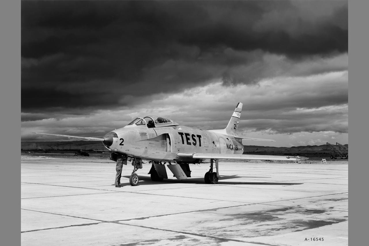
YF-93A (AF48-318 NACA-151) Flight evaluation and comparison of a NACA submerged inlet and a scoop inlet. The YF-93A's were the first aircraft to use flush NACA engine inlets. Note: Used in Flight Research at Ames; 57 Years of Development and Validation of Aeronautical Technology NASA SP-1998-3300 Fig.25
The FJ33 Engine Inlet from Williams International being tested in the Icing Research Tunnel
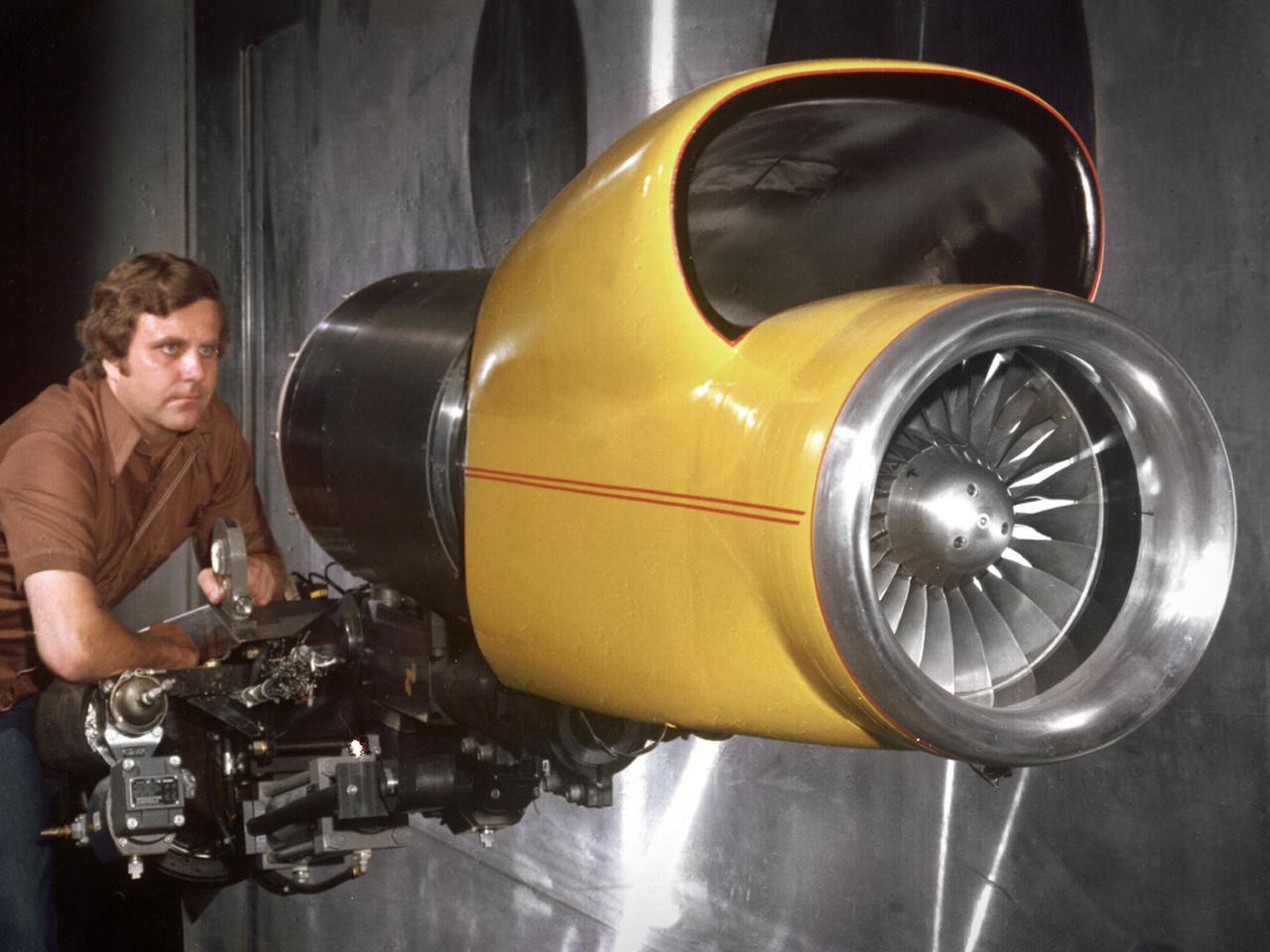
Center Director John McCarthy, left, and researcher Al Johns pose with a one-third scale model of a Grumman Aerospace tilt engine nacelle for Vertical and Short Takeoff and Landing (V/STOL) in the 9- by 15-Foot Low Speed Wind Tunnel at the National Aeronautics and Space Administration (NASA) Lewis Research Center. Lewis researchers had been studying tilt nacelle and inlet issues for several years. One area of concern was the inlet flow separation during the transition from horizontal to vertical flight. The separation of air flow from the inlet’s internal components could significantly stress the fan blades or cause a loss of thrust. In 1978 NASA researchers Robert Williams and Al Johns teamed with Grumman’s H.C. Potonides to develop a series of tests in the Lewis 9- by 15-foot tunnel to study a device designed to delay the flow separation by blowing additional air into the inlet. A jet of air, supplied through the hose on the right, was blown over the inlet surfaces. The researchers verified that the air jet slowed the flow separation. They found that the blowing on boundary layer control resulted in a doubling of the angle-of-attack and decreases in compressor blade stresses and fan distortion. The tests were the first time the concept of blowing air for boundary layer control was demonstrated. Boundary layer control devices like this could result in smaller and lighter V/STOL inlets.
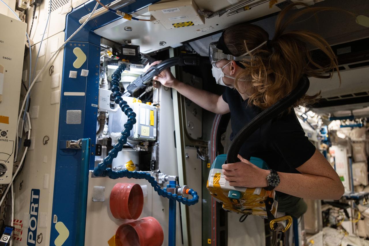
iss072e919611 (April 2, 2025) --- NASA astronaut and Expedition 72 Flight Engineer Nichole Ayers cleans ventilation system fans and inlets inside the International Space Station's Destiny labortory module.

Date: Dec 6, 1951 NACA Photographer North American YF-93 with submerged divergent-wall engine-air inlet. Maximum high-speed capability of Mach 1.03 was obtained with afterbrner on. Tests were conducted to compare high-speed performance of the YF-93 NACA-139 airplane with different inlet configurations. (Mar 1953)
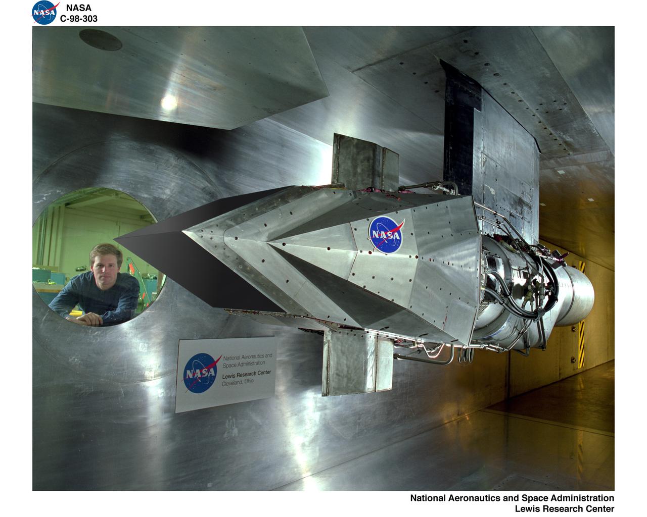
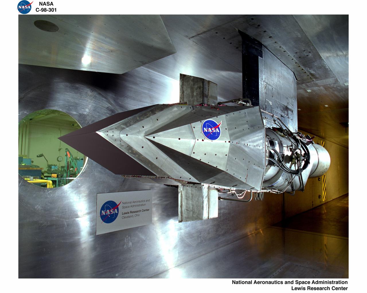
A technician checks a 0.25-scale engine model of a Vought Corporation V-530 engine in the test section of the 10- by 10-Foot Supersonic Wind Tunnel at the National Aeronautics and Space Administration (NASA) Lewis Research Center. Vought created a low-drag tandem-fan Vertical/Short and Takeoff and Landing (V/STOL) engine in the mid-1970s, designated as the V-530. The first fan on the tandem-fan engine was supplied with air through a traditional subsonic inlet, seen on the lower front of the engine. The air was exhausted through the nacelle during normal flight and directed down during takeoffs. The rear fan was supplied by the oval-shaped top inlet during all phases of the flight. The second fan exhausted its air through a rear vectorable nozzle. NASA Lewis and Vought partnered in the late 1970s to collect an array of inlet and nozzle design information on the tandem fan engines for the Navy. Vought created this .25-scale model of the V-530 for extensive testing in Lewis' 10- by 10-foot tunnel. During an early series of tests, the front fan was covered, and a turbofan simulator was used to supply air to the rear fan. The researchers then analyzed the performance of only the front fan inlet. During the final series of tests, the flow from the front fan was used to supply airflow to the rear fan. The researchers studied the inlet's recovery, distortion, and angle-of-attack limits over various flight conditions.
A Highly Maneuverable Aircraft Technology (HiMAT) inlet model installed in the test section of the 8- by 6-Foot Supersonic Wind Tunnel at the National Aeronautics and Space Administration (NASA) Lewis Research Center. Engineers at the Ames Research Center, Dryden Flight Research Center, and Rockwell International designed two pilotless subscale HiMAT vehicles in the mid-1970s to study new design concepts for fighter aircraft in the transonic realm without risking the lives of test pilots. The aircraft used sophisticated technologies such as advanced aerodynamics, composite materials, digital integrated propulsion control, and digital fly-by-wire control systems. In late 1977 NASA Lewis studied the HiMAT’s General Electric J85-21 jet engine in the Propulsion Systems Laboratory. The researchers charted the inlet quality with various combinations anti-distortion screens. HiMAT employed a relatively short and curved inlet compared to actual fighter jets. In the spring of 1979, Larry Smith led an in-depth analysis of the HiMAT inlet in the 8- by 6 tunnel. The researchers installed vortex generators to battle flow separation in the diffuser. The two HiMAT aircraft performed 11 hours of flying over the course of 26 missions from mid-1979 to January 1983 at Dryden and Ames. Although the HiMAT vehicles were considered to be overly complex and expensive, the program yielded a wealth of data that would validate computer-based design tools.
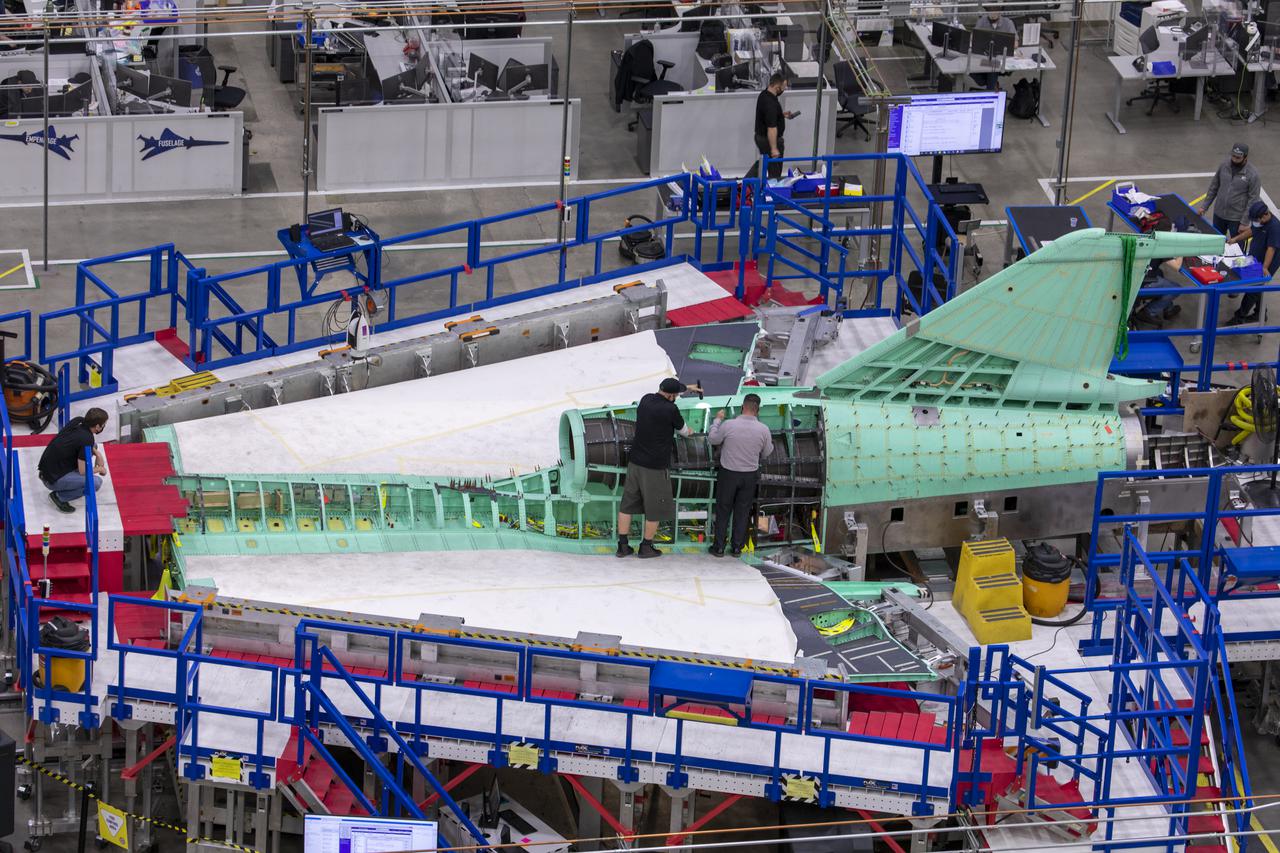
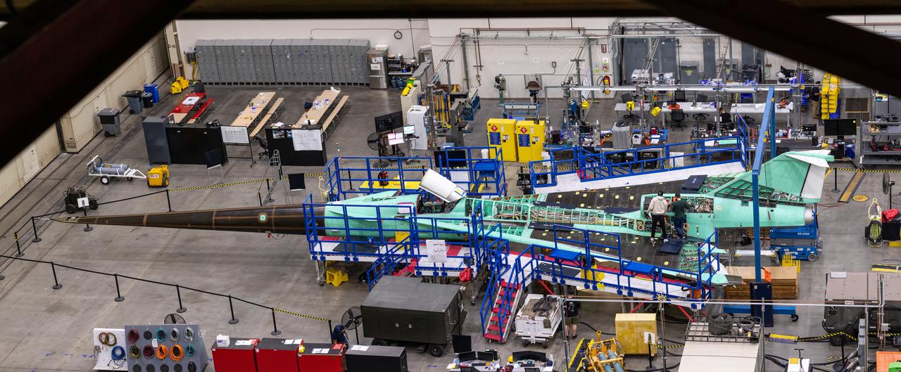
This overhead shot of the X-59 assembly during Spring 2021 shows assembly with technicians working at the engine inlet section where the engine will be located on the aircraft. Lockheed Martin Photography By Garry Tice 1011 Lockheed Way, Palmdale, Ca. 93599 Event: Manufacture Area From Above Date: 3/30/2021
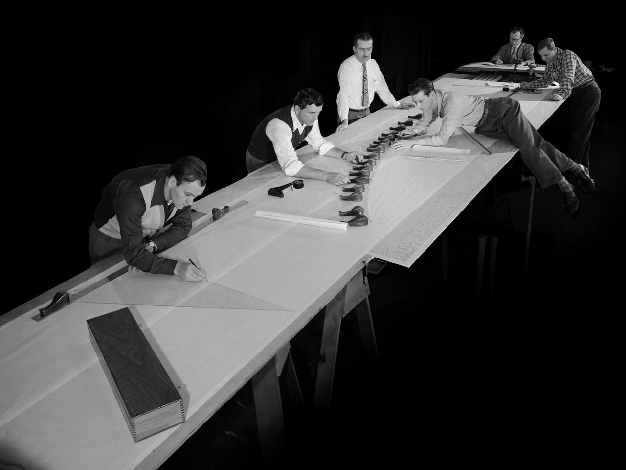
Draftsmen in the Materials and Stresses Building at the National Advisory Committee for Aeronautics (NACA) Lewis Flight Propulsion Laboratory create a template for a compressor using actual compressor blades. The Compressor and Turbine Division contained four sections of researchers dedicated to creating better engine components. The Materials and Thermodynamics Division studied the strength, durability, heat transfer characteristics, and physical composition of various materials. The two divisions were important to the research and development of new aircraft engines. The constant battle to increase the engine’s thrust while decreasing its overall weight resulted in additional stress on jet engine components, particularly compressors. As speed and maneuverability were enhanced, the strain on the engines and inlets grew. For decades NACA Lewis researchers continually sought to improve compressor blade design, develop stronger composite materials, and minimize flutter and inlet distortions.
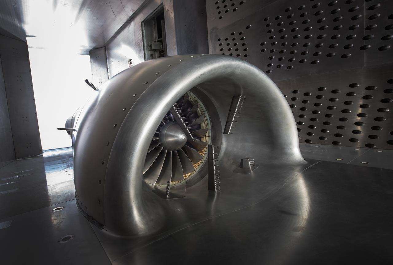
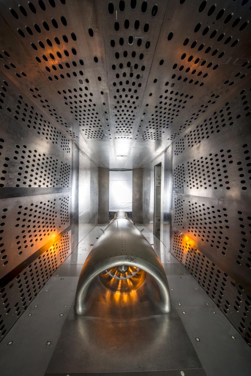
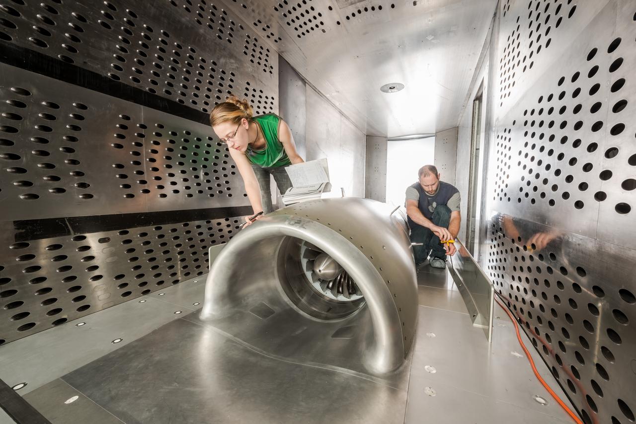
In an effort to improve fuel efficiency, NASA and the aircraft industry are rethinking aircraft design. Inside the 8' x 6' wind tunnel at NASA Glenn, engineers recently tested a fan and inlet design, commonly called a propulsor, which could use four to eight percent less fuel than today's advanced aircraft.
In an effort to improve fuel efficiency, NASA and the aircraft industry are rethinking aircraft design. Inside the 8' x 6' wind tunnel at NASA Glenn, engineers recently tested a fan and inlet design, commonly called a propulsor, which could use four to eight percent less fuel than today's advanced aircraft.
In an effort to improve fuel efficiency, NASA and the aircraft industry are rethinking aircraft design. Inside the 8' x 6' wind tunnel at NASA Glenn, engineers recently tested a fan and inlet design, commonly called a propulsor, which could use four to eight percent less fuel than today's advanced aircraft.
In an effort to improve fuel efficiency, NASA and the aircraft industry are rethinking aircraft design. Inside the 8' x 6' wind tunnel at NASA Glenn, engineers recently tested a fan and inlet design, commonly called a propulsor, which could use four to eight percent less fuel than today's advanced aircraft.
In an effort to improve fuel efficiency, NASA and the aircraft industry are rethinking aircraft design. Inside the 8' x 6' wind tunnel at NASA Glenn, engineers recently tested a fan and inlet design, commonly called a propulsor, which could use four to eight percent less fuel than today's advanced aircraft.
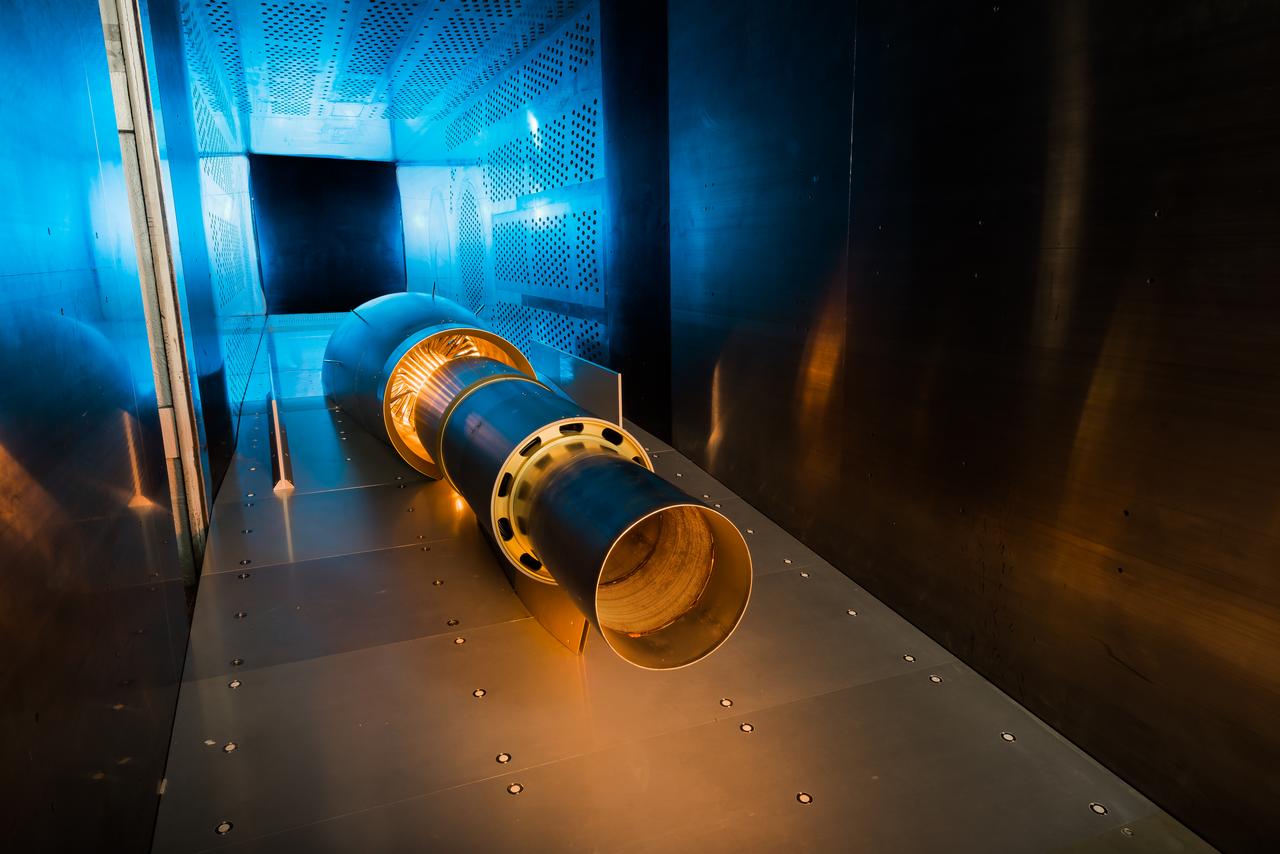
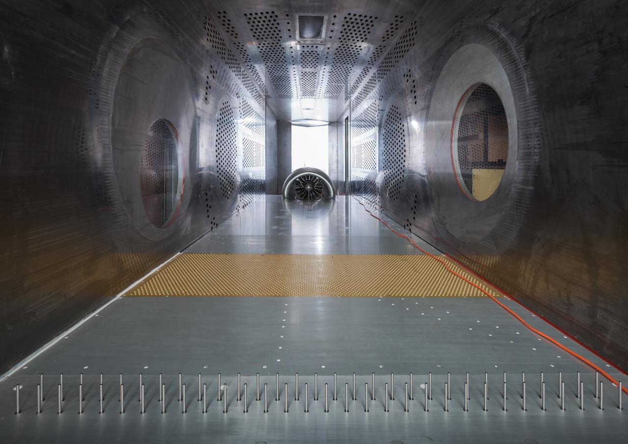
The 10- by 10-Foot Supersonic Wind Tunnel (10×10) is the largest and fastest wind tunnel facility at NASA’s Glenn Research Center and is specifically designed to test supersonic propulsion components from inlets and nozzles to full-scale jet and rocket engines.
In an effort to improve fuel efficiency, NASA and the aircraft industry are rethinking aircraft design. Inside the 8' x 6' wind tunnel at NASA Glenn, engineers recently tested a fan and inlet design, commonly called a propulsor, which could use four to eight percent less fuel than today's advanced aircraft.
In an effort to improve fuel efficiency, NASA and the aircraft industry are rethinking aircraft design. Inside the 8' x 6' wind tunnel at NASA Glenn, engineers recently tested a fan and inlet design, commonly called a propulsor, which could use four to eight percent less fuel than today's advanced aircraft.

In an effort to improve fuel efficiency, NASA and the aircraft industry are rethinking aircraft design. Inside the 8' x 6' wind tunnel at NASA Glenn, engineers recently tested a fan and inlet design, commonly called a propulsor, which could use four to eight percent less fuel than today's advanced aircraft.

In an effort to improve fuel efficiency, NASA and the aircraft industry are rethinking aircraft design. Inside the 8' x 6' wind tunnel at NASA Glenn, engineers recently tested a fan and inlet design, commonly called a propulsor, which could use four to eight percent less fuel than today's advanced aircraft.
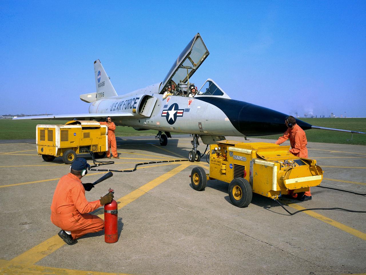
National Aeronautics and Space Administration (NASA) pilot Cliff Crabbs and the flight operations crew prepare a Convair F-106B Delta Dart for a flight from the Lewis Research Center in Cleveland, Ohio. NASA acquired the aircraft three years earlier to investigate noise-reducing inlet and nozzle designs for the supersonic transport engine program. Two General Electric J85 engines were installed underneath the aircraft’s delta wings to simulate the general shape of the supersonic transport’s engines. One of the engines was modified with experimental inlet or nozzle configurations. The unmodified engine was used for comparison. Most F-106B flights were flown in a 200-mile path over the lake between Buffalo and Sandusky, known as the Lake Erie Corridor. The 1100-miles per hour flight took only 11 minutes at an altitude of 30,000 feet. The aircraft almost always returned with a depleted fuel supply so a Visual Flight Rules operation was required. Following the crash of another jet fighter at Lewis in July 1969, the F-106s were stationed at Selfridge Air Force Base in Michigan. NASA pilots flew transport planes each morning to the base before commencing the F-106B missions.
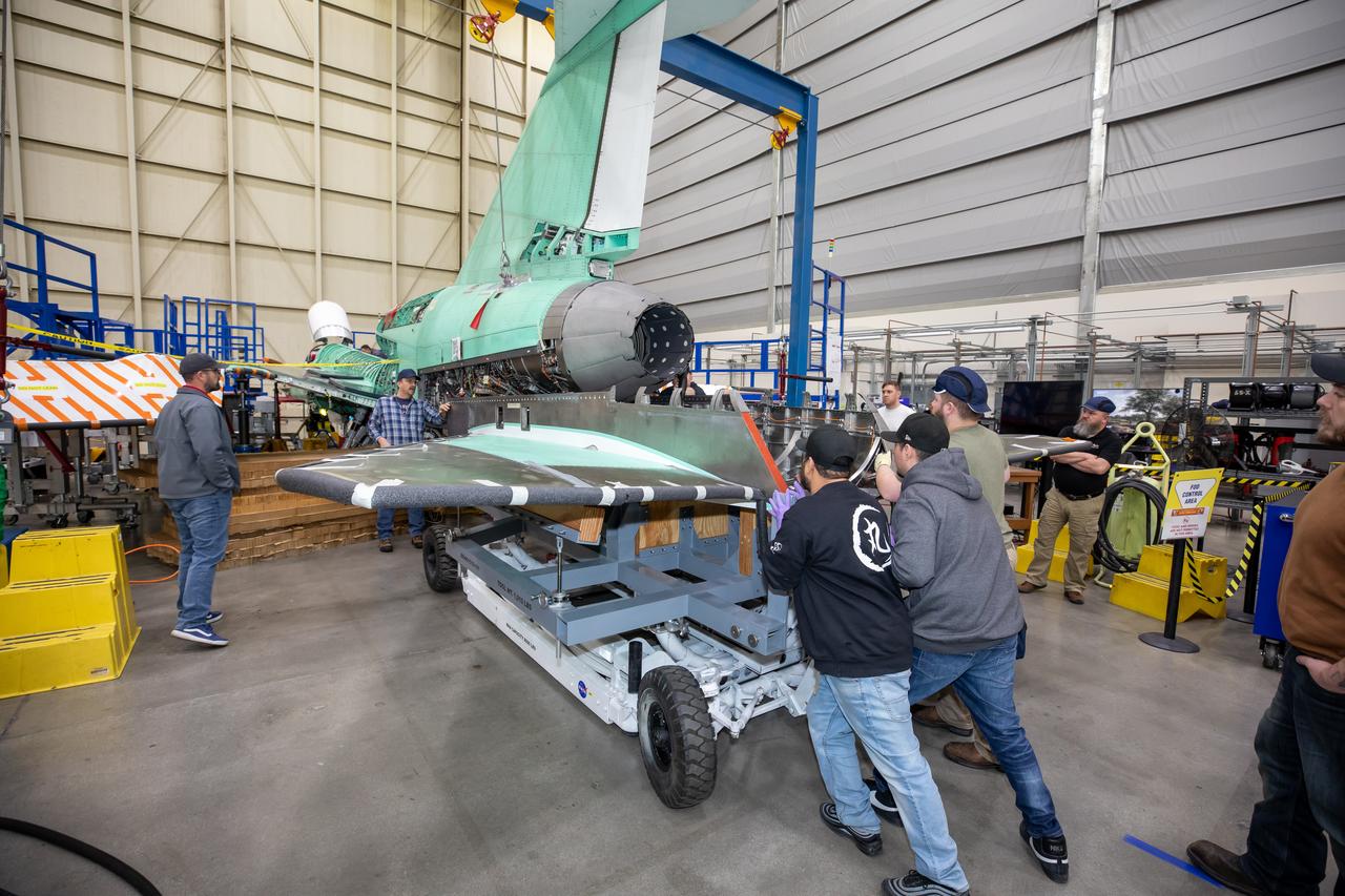
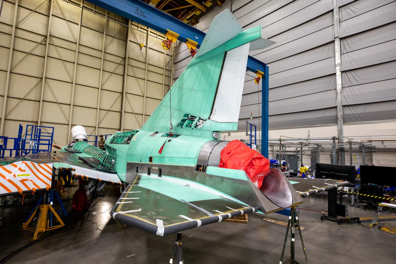
This image shows the X-59 aircraft’s lower empennage structure, or tail section of the plane, that was installed. The stabilators, the outer surfaces also seen in the photo, attach to the lower empennage and are used to help regulate the aircraft pitch which controls the up and down movement of the motion of the plane. The 13-foot engine will pack 22,000 pounds of propulsion and energy and power the X-plane to its planned cruising speed of Mach 1.4. Once complete, the X-59 aircraft will demonstrate the ability to fly supersonic while reducing the loud sonic boom to a quiet sonic thump and help enable commercial supersonic air travel over land. This aircraft is the centerpiece of NASA’s Quesst mission.
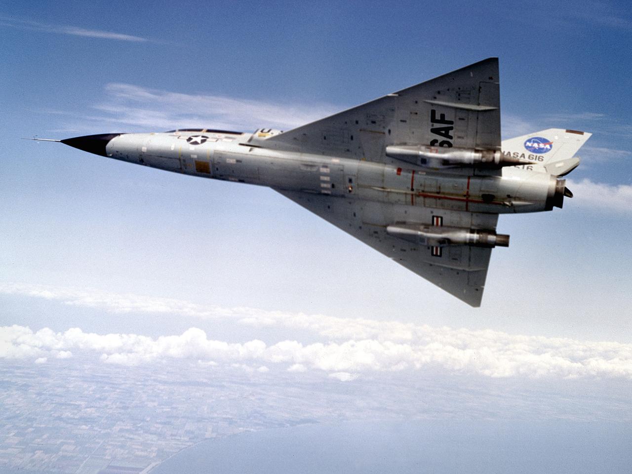
A Convair F-106B Delta Dart rolls to the right to reveal the two research engines installed under its wings by the National Aeronautics and Space Administration (NASA) Lewis Research Center. Lewis acquired the aircraft in October of 1966 to study inlet and nozzle designs for the supersonic transport engine program. Two General Electric J85 engines were mounted beneath the F-106B’s wings and operated from Mach 1 to 1.5. The right wing always carried reference nozzle for which the performance was known. Six supersonic nozzle variations and two inlets were tested on the left engine. The designs had already been studied in the Lewis wind tunnels, but those tests were limited by shock waves in the tunnels. Most F-106B flights were flown in a 200-mile path over the lake between Buffalo and Sandusky, known as the Lake Erie Corridor. The 1100-mile-per-hour flight took only 11 minutes at an altitude of 30,000 feet. The aircraft almost always returned with a depleted fuel supply so a Visual Flight Rules operation was required. Following the crash of another jet fighter at Lewis in July 1969, the F-106s were stationed at Selfridge Air Force Base in Michigan. NASA pilots flew transport planes each morning to the base before commencing the F-106B missions. After the supersonic transport program was cancelled, the F-106B was used as a test bed for additional engine exhaust nozzle configurations. The F-106B was also used to test inlet configurations for the noise reduction program.
The Icing Research Tunnel (IRT) is the longest running, icing facility in the world and has been in operation since 1944. Most ice protection technologies in use today were largely developed at this facility. In this facility, natural icing conditions, such as the clouds being created here, are produced to test the effects of icing conditions on aircraft components such as wings tails and engine inlets.
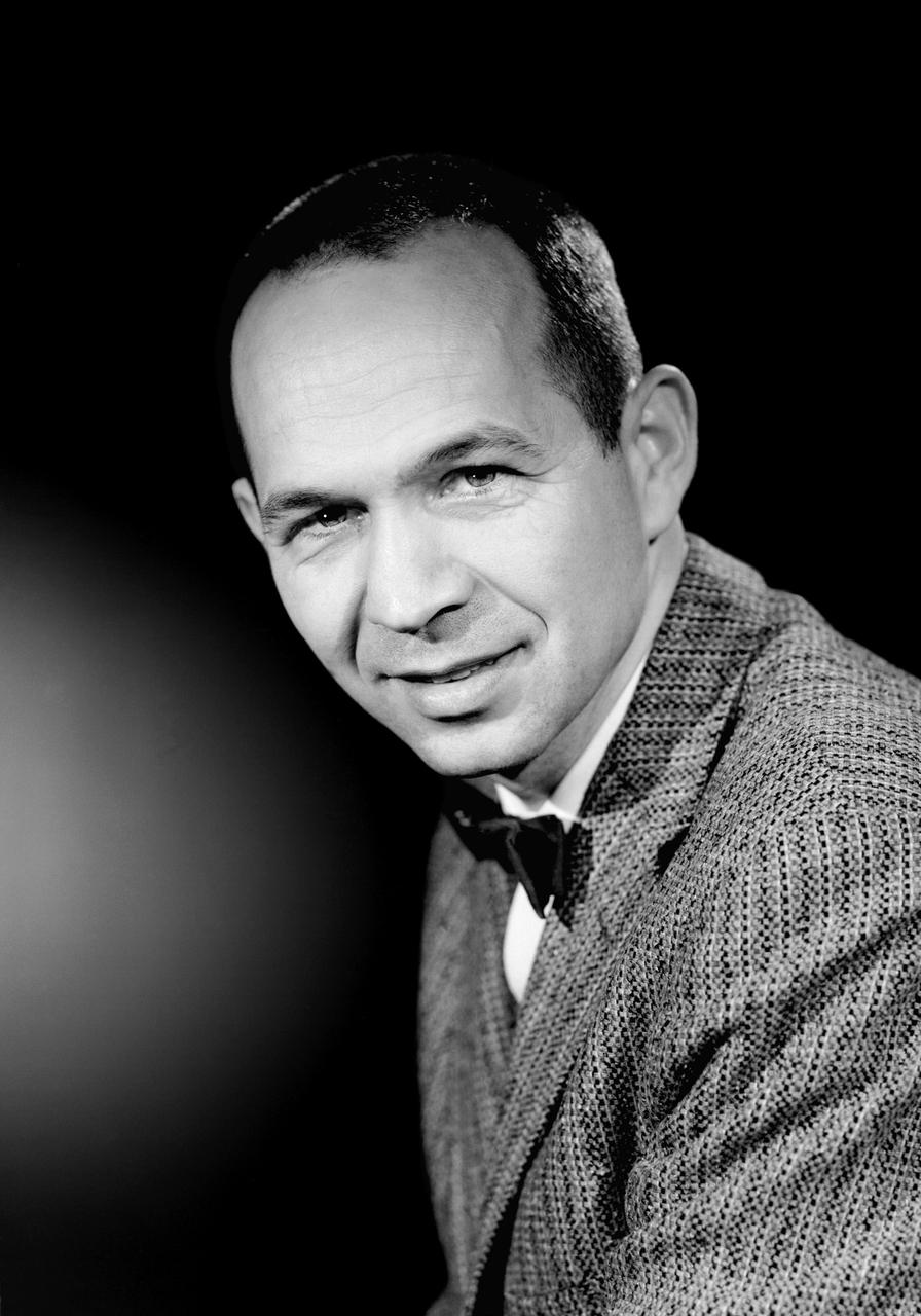
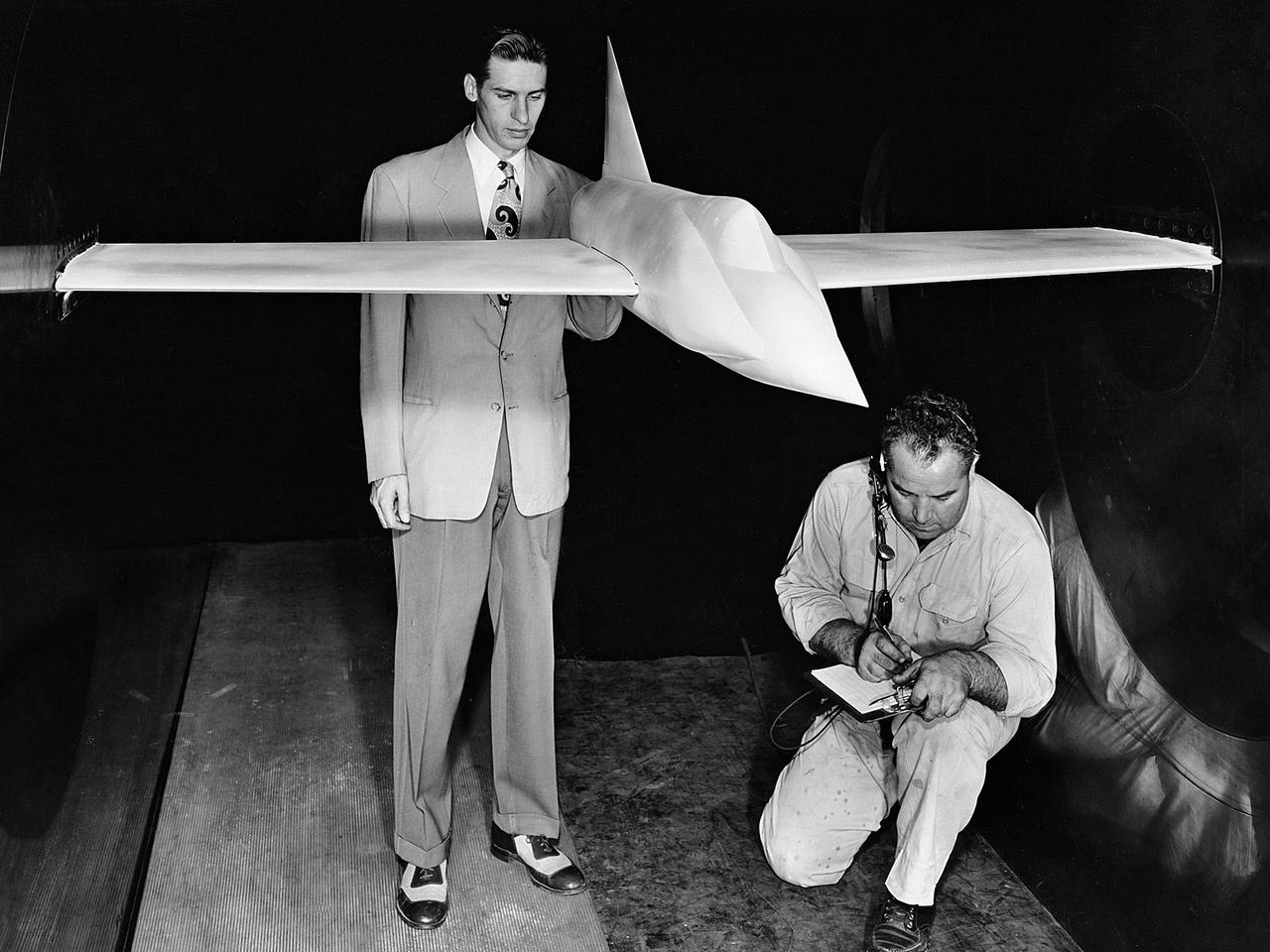
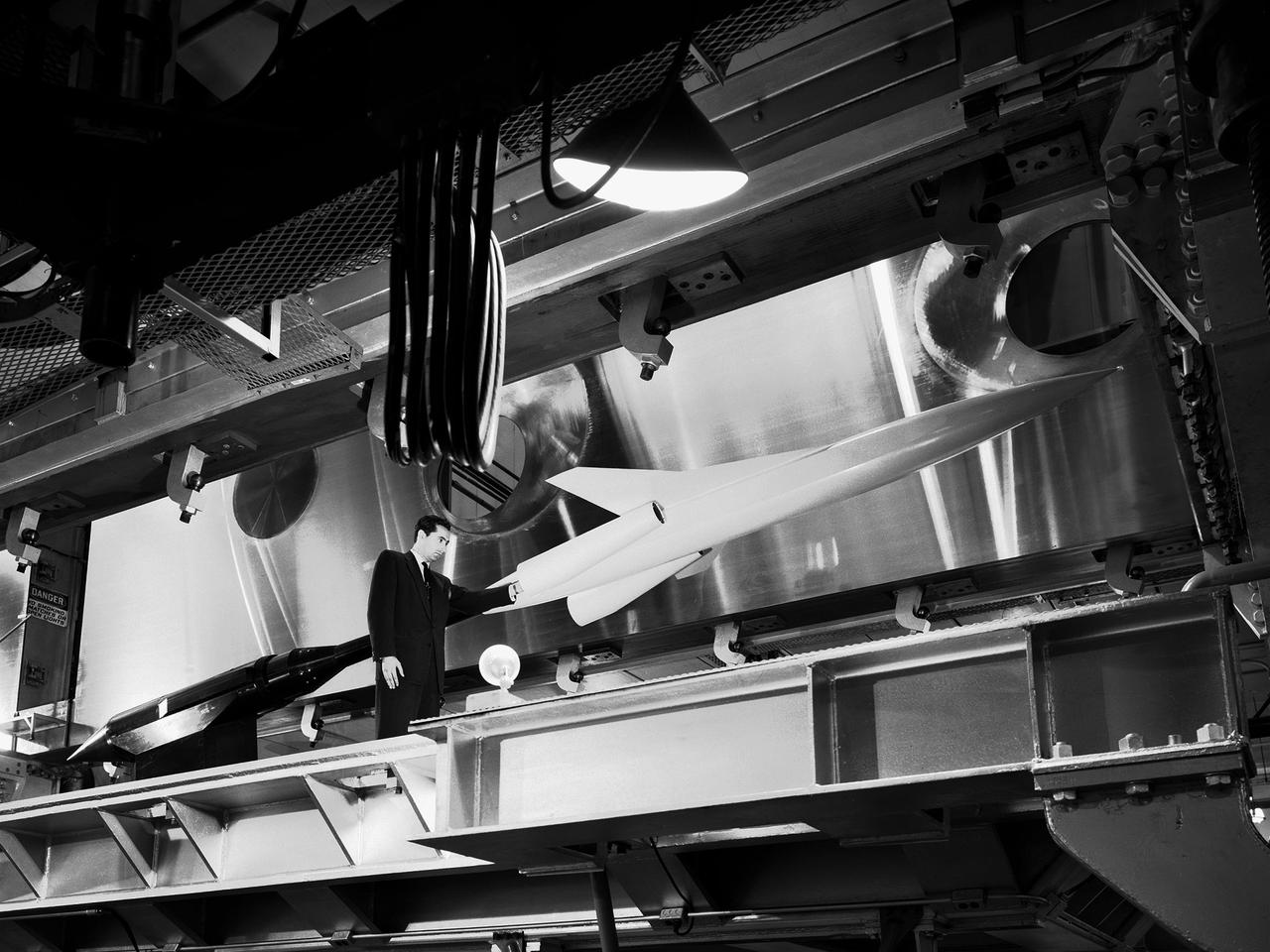
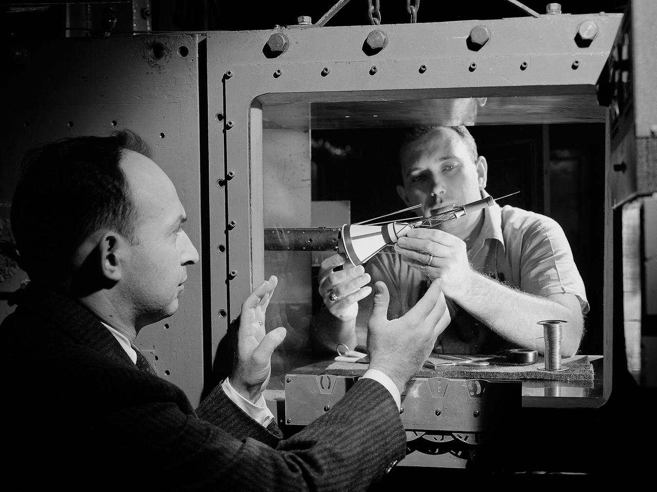
L59-1497-6 Maxime A. Faget was born in British Honduras in 1921, the son of an honored physician of the U.S. Public Health Service. In 1943 he earned a B.S. in mechanical engineering from Louisiana State University. After service as a navy submarine officer, he joined the Langley staff in 1946 as a member of the Pilotless Aircraft Research Division. His early work for PARD involved the invention of choking inlets for ramjets and a flight Mach meter. Photograph published in Engineer in Charge: A History of the Langley Aeronautical Laboratory, 1917-1958 by James R. Hansen. Page 379.
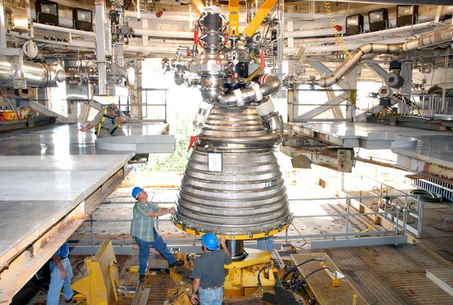
Core components of the J-2X engine being designed for NASA's Constellation Program recently were installed on the A-1 Test Stand at NASA's Stennis Space Center near Bay St. Louis, Miss. Tests of the components, known as Powerpack 1A, will be conducted from November 2007 through February 2008. The Powerpack 1A test article consists of a gas generator and engine turbopumps originally developed for the Apollo Program that put Americans on the moon in the late 1960s and early 1970s. Engineers are testing these heritage components to obtain data that will help them modify the turbomachinery to meet the higher performance requirements of the Ares I and Ares V launch vehicles. The upcoming tests will simulate inlet and outlet conditions that would be present on the turbomachinery during a full-up engine hot-fire test.
Here is a close-up of the GE F414 engine, from the aft deck or rear, before the tail section of the X-59 is lifted into place and attached to the aircraft. The aft deck helps control the shockwaves at the end of the aircraft and reduce the noise of a sonic boom to more of a sonic thump.
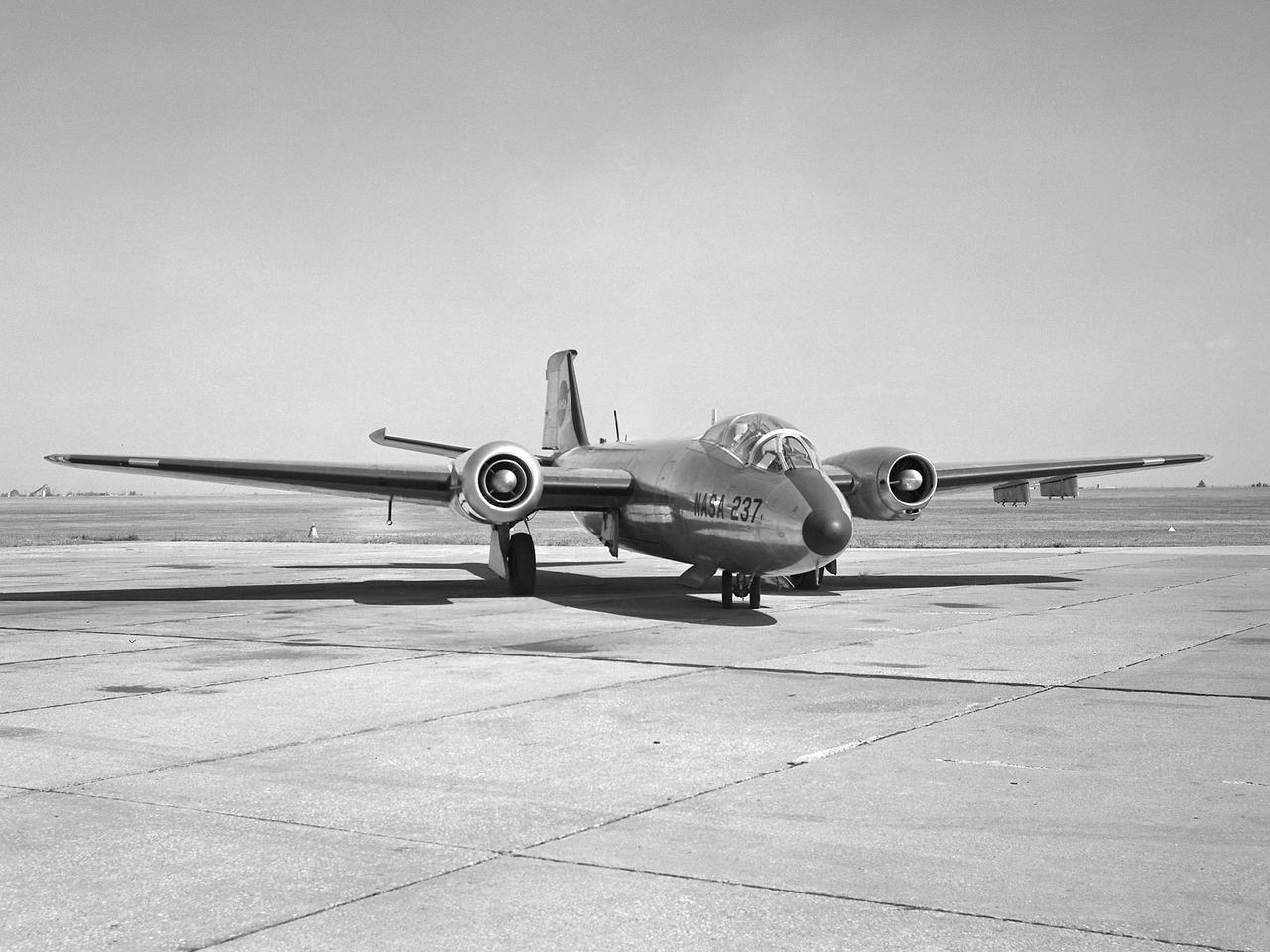
A Martin B-57B Canberra outfitted with a noise suppressor on its right engine at the National Aeronautics and Space Administration (NASA) Lewis Research Center. The aircraft was being prepared for the October 1966 Inspection of the center. The Inspection also marked Lewis’ twentieth anniversary. Lewis researchers had been studying engine noise for almost a decade, but the problem seemed to be increasing in the mid-1960s with heavier airline traffic and larger engines. Researchers discovered early on that the majority of the noise did not emanate from the engine itself, but from the mixing of the hot exhaust gasses with the atmosphere. Attempts to reduce the turbulence using new exhaust nozzles were successful but often resulted in decreased engine performance. The researchers decided to try to lower the jet nozzle exit velocity without decreasing its thrust. The inlet mass air flow had to be increased to accomplish this. The Lewis B-57B was powered by two Wright Aeronautical J65 turbojets. Lewis engineers modified the stators on the two engines to simulate the noise levels from more-modern turbofan engines. A noise suppressor was added to only one of the two engines, seen here on the left. The engines were run one at a time at power levels similar to landing while the aircraft sat on the Lewis hangar apron. A microphone and recording equipment was setup to capture the noise levels. The engine with the suppressor produced 13 fewer decibels than the standard engine.
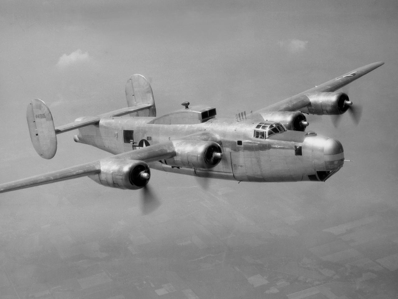
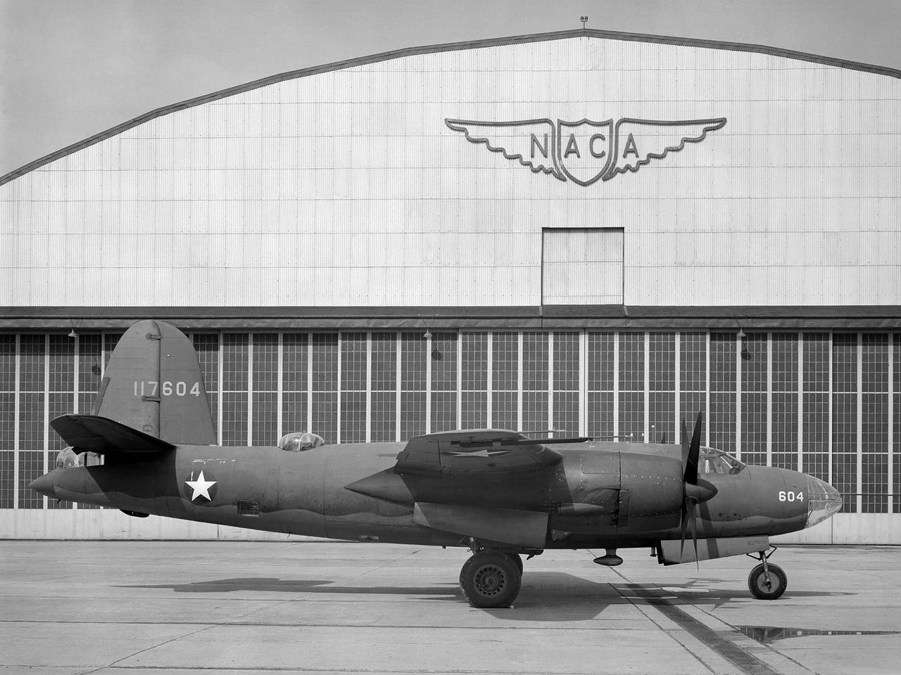
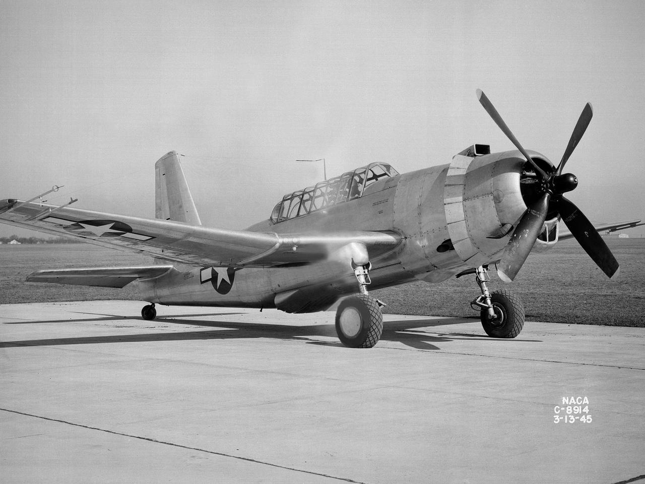
A Consolidated B-25M Liberator modified for icing research by the National Advisory Committee for Aeronautics (NACA) Lewis Flight Propulsion Laboratory. NACA Lewis performed a limited amount of icing research during World War II, but the program expanded significantly in 1946. The accumulation of ice on aircraft was a continual problem. The ice formations could result in extra weight, aerodynamic penalties, and blockage engine inlets. Although the Lewis icing researchers utilized numerous aircraft, the program’s two workhorses were the B-24M Liberator, seen here, and a North American XB-25E Mitchell. The Consolidated Aircraft Company created the four-engine bomber in the early 1940s. During World War II the bomber was employed on long-duration bombing missions in both Europe and the Pacific. Production of the B-24M version did not begin until October 1944 with the end of the war in Europe approaching. This resulted in scores of unneeded bombers when hostilities ended. This B-24M arrived at the NACA Lewis laboratory in November 1945. At Lewis the B-24M was repeatedly modified to study ice accretion on aircraft components. Researchers analyzed different anti-icing and deicing strategies and gathered statistical ice measurement data. The B-24M was also used to study ice buildup on jet engines. A General Electric I-16 engine was installed in the aircraft’s waist compartment with an air scoop on the top of the aircraft to duct air to the engine. Water spray nozzles inside the aircraft were employed to simulate icing conditions at the turbojet’s inlet.
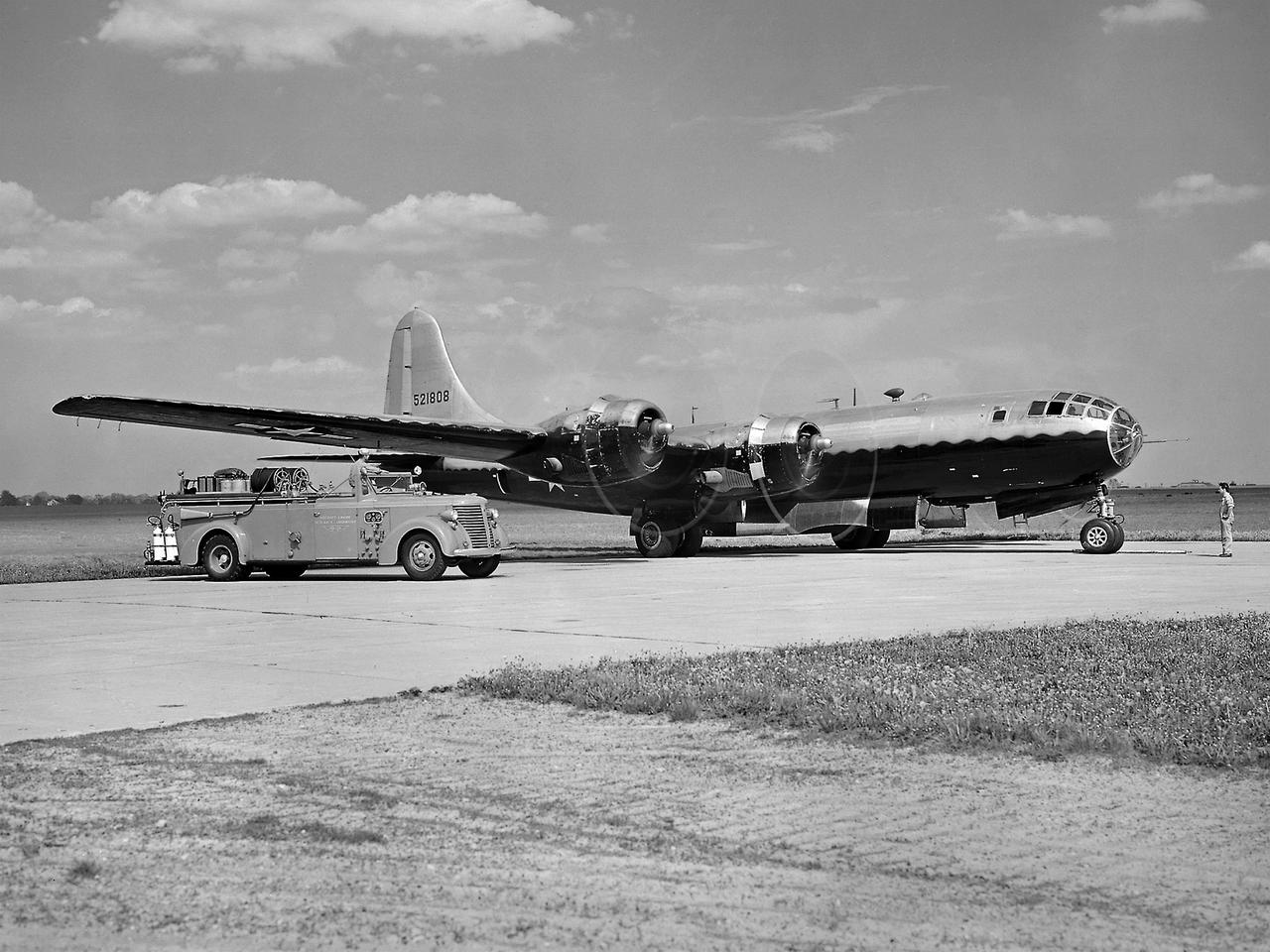
The resolution of the Boeing B-29 Superfortress’ engine cooling problems was one of the Aircraft Engine Research Laboratory’s (AERL) key contributions to the World War II effort. The B-29 leapfrogged previous bombers in size, speed, and altitude capabilities. The B–29 was intended to soar above anti-aircraft fire and make pinpoint bomb drops onto strategic targets. Four Wright Aeronautical R-3350 engines powered the massive aircraft. The engines, however, frequently strained and overheated due to payload overloading. This resulted in a growing number of engine fires that often resulted in crashes. The military asked the NACA to tackle the overheating issue. Full-scale engine tests on a R–3350 engine in the Prop House demonstrated that a NACA-designed impeller increased the fuel injection system’s flow rate. Single-cylinder studies resolved a valve failure problem by a slight extension of the cylinder head, and researchers in the Engine Research Building combated uneven heating with a new fuel injection system. Investigations during the summer of 1944 in the Altitude Wind Tunnel, which could simulate flight conditions at high altitudes, led to reduction of drag and improved air flow by reshaping the cowling inlet and outlet. The NACA modifications were then flight tested on a B-29 bomber that was brought to the AERL.
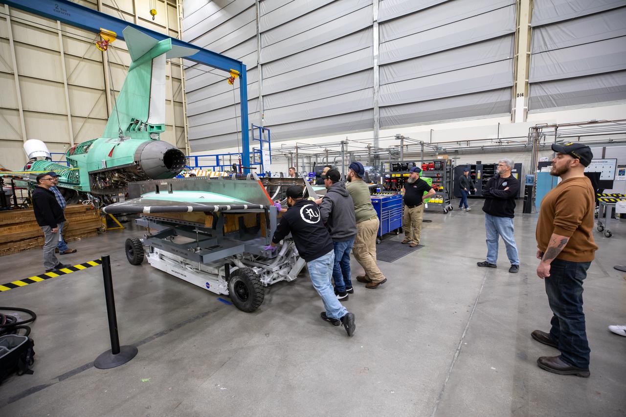
The X-59 team at Lockheed Martin Skunk Works in Palmdale, California, load the lower empennage - the tail section - into place. The surfaces used to control the tilt of the airplane are called stabilators and are connected to the lower empennage. The X-59 is the centerpiece of NASA’s Quesst mission, which could help enable commercial supersonic air travel over land.
The X-59 team at Lockheed Martin Skunk Works in Palmdale, California, load the lower empennage - the tail section - into place. The surfaces used to control the tilt of the airplane are called stabilators and are connected to the lower empennage. The X-59 is the centerpiece of NASA’s Quesst mission, which could help enable commercial supersonic air travel over land.
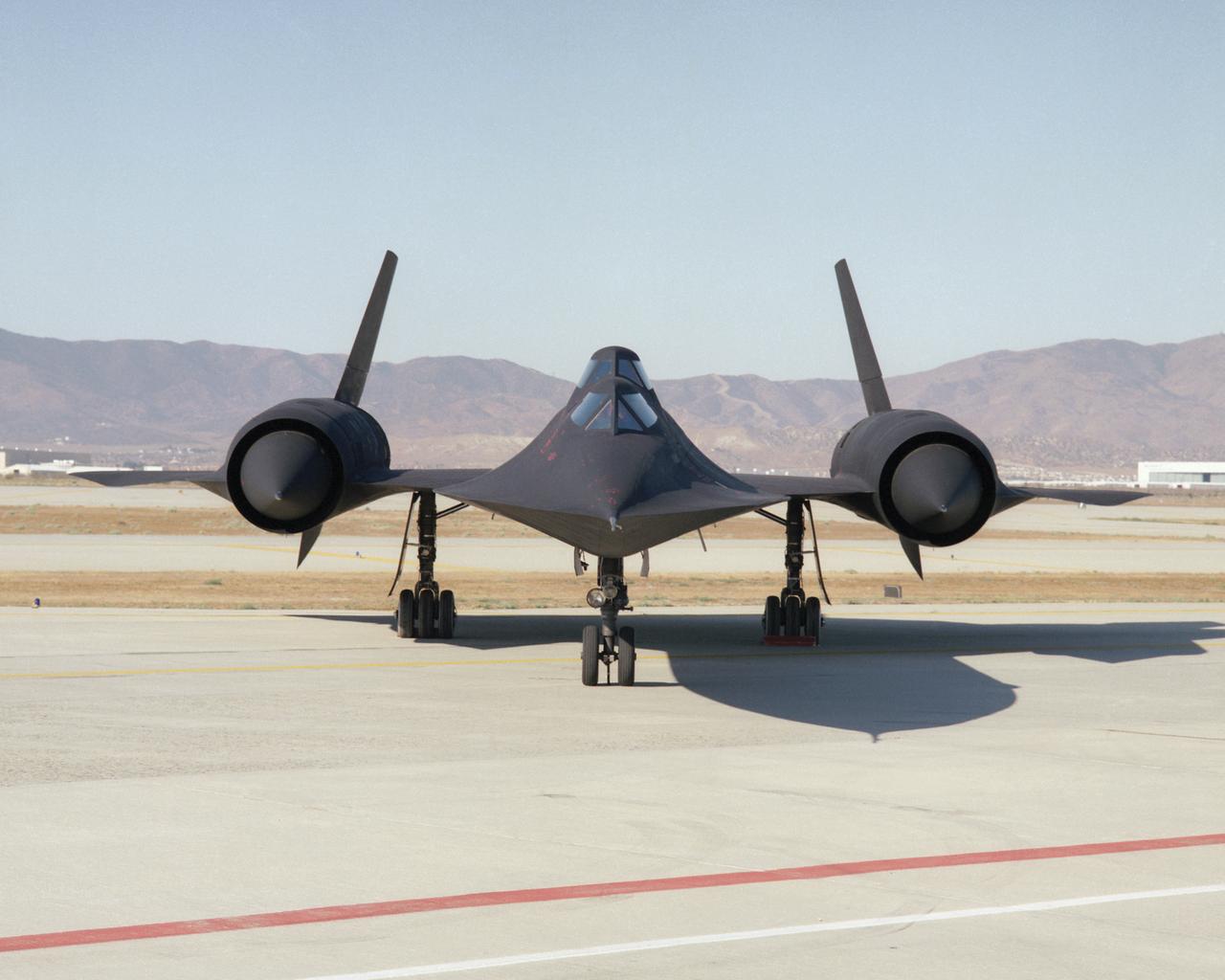
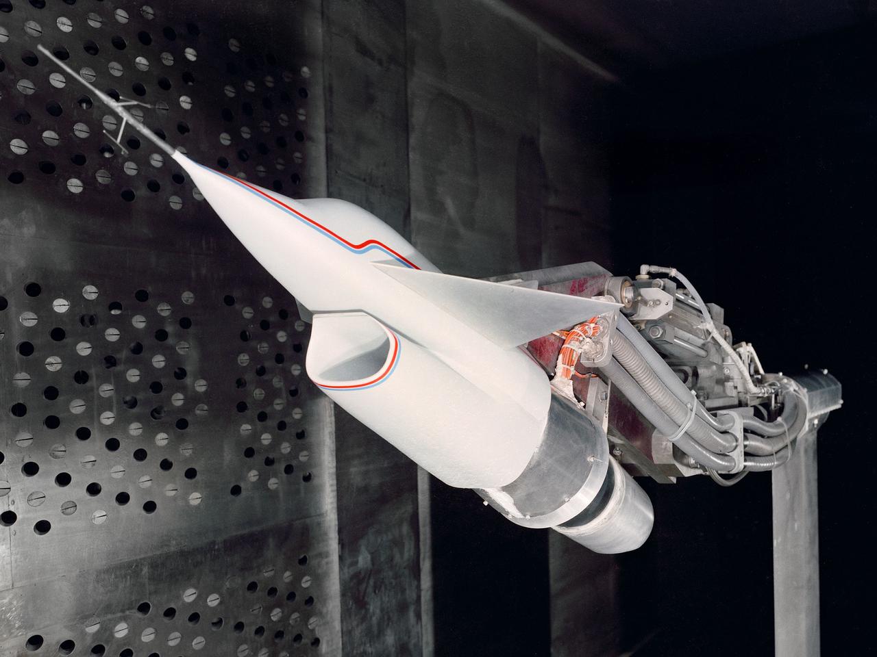
This photo shows a head-on view of NASA's SR-71B, used for pilot proficiency and training, on the ramp at the Air Force's Plant 42 in Palmdale, California, shortly before delivery to the Ames-Dryden Flight Research Facility (later, Dryden Flight Research Center) at Edwards, California. NASA operated two of these unique aircraft, an SR-71A, for high-speed, high altitude research, and this SR- 71B pilot trainer for most of the decade of the 1990s. The "B" model is special because of its raised rear cockpit, which provided a second pilot position so a trainer and an experienced pilot could both see what was going on during flights. The SR-71 was designed and built by the Lockheed Skunk Works, now the Lockheed Martin Skunk Works. Studies have shown that less than 20 percent of the total thrust used to fly at Mach 3 is produced by the basic engine itself. The balance of the total thrust is produced by the unique design of the engine inlet and "moveable spike" system at the front of the engine nacelles, and by the ejector nozzles at the exhaust which burn air compressed in the engine bypass system. Data from the SR-71 high speed research program will be used to aid designers of future supersonic/hypersonic aircraft and propulsion systems, including a high speed civil transport.
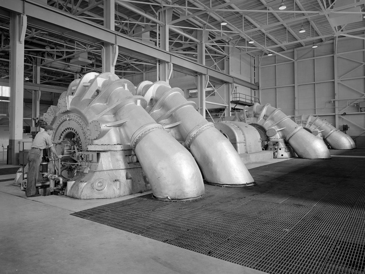
The Propulsion Systems Laboratory’s exhaust system was expanded in 1955 at the National Advisory Committee for Aeronautics (NACA) Lewis Flight Propulsion Laboratory. The facility contained two altitude chambers that were first used to study the increasingly-powerful jet engines of the early 1950s and the ramjets for missile programs such as Navaho and Bomarc. Later, the facility tested large rocket engines and a variety of turbofan engines. The exhaust system served two roles: reducing the density of the air in the test chambers to simulate high altitudes and removing the hot gases exhausted by the engines being tested. These tasks were accomplished by large Roots-Connersville exhauster equipment in the Equipment Building. The original configuration could exhaust the 3500° F gases at a rate of 100 pounds per second when the simulated altitude was 50,000 feet. In 1955, three years after operation started, a fourth line of exhausters was added. There were three centrifugal exhausters capable of supplying 166 pounds of air per second at the test chamber altitude of 50,000 feet or 384 pounds per second at 32,000 feet. These exhausters had two first-stage castings driven by a 10,000-horsepower motor; one second; one third; and one fourth-stage casting driven by a 16,500-horsepower motor. The total inlet volume of the exhausters is 1,650,000 cubic feet of gas per minute. The exhausters were continually improved and upgraded over the years.

An inlet duct lowered into the 20-foot diameter test section of the Altitude Wind Tunnel at the National Advisory Committee for Aeronautics (NACA) Lewis Flight Propulsion Laboratory. Engines and hardware were prepared in the facility’s shop area. The test articles were lifted by a two-rail Shaw box crane through the high-bay and the second-story test chamber before being lowered into the test section. Technicians then spent days or weeks hooking up the supply lines and data recording telemetry. The engines were mounted on wingspans that stretched across the test section. The wingtips attached to the balance frame’s trunnions, which could adjust the angle of attack. The balance frame included six devices that recorded data and controlled the engine. The measurements were visible in banks of manometer boards next to the control room. Photographs recorded the pressure levels in the manometer tubes, and the computing staff manually converted the data into useful measurements. A mechanical pulley system was used to raise and lower the tunnel’s large clamshell lid into place. The lid was sealed into place using hand-turned locks accessible from the viewing platform. The lid had viewing windows above and below the test article, which permitted the filming and visual inspection of the tests.

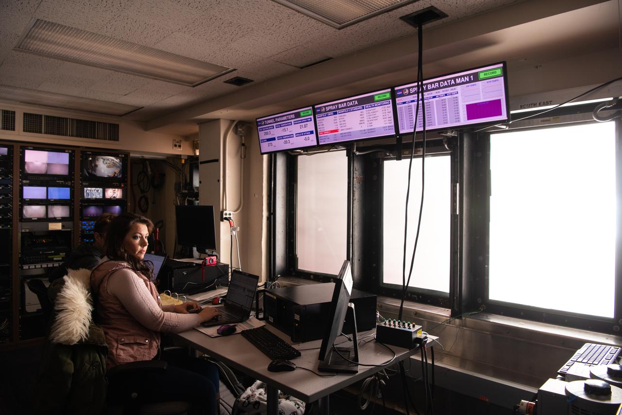
Technicians set up test hardware inside the test section of the Icing Research Tunnel at the National Aeronautics and Space Administration (NASA) Lewis Research Center. The Icing Research Tunnel was built in the early 1940s to study the formation of ice on aircraft surfaces and develop methods of preventing or eradicating that ice. Ice buildup is dangerous because it adds extra weight, effects aerodynamics, and sometimes blocks air flow through engines. The Icing Research Tunnel is a closed-loop atmospheric wind tunnel with a 6- by 9-foot test section. The tunnel can produce speeds up to 300 miles per hour and temperatures from 30 to -45 °F. NACA engineers struggled initially to perfect a spray bar system to introduce moisture into the airstream. The tunnel was shut down in the late 1950s as the center focused its energy exclusively on space. Industrial customers began using the tunnel sporadically, then steadily, in the 1960s. Boeing, Aerojet, Lockheed, Sikorsky, Beech and others ran tests during the 1960s. Boeing analyzed engine inlets for the CH-47 Chinook, CH-46 (Sea Knight) and CH-113. This photograph was taken during a series of 100 ice-phobic coatings for the Federal Aviation Administration. They found that many of the coatings reduced ice adhesion to the test sample, but they could not be used for aircraft applications.
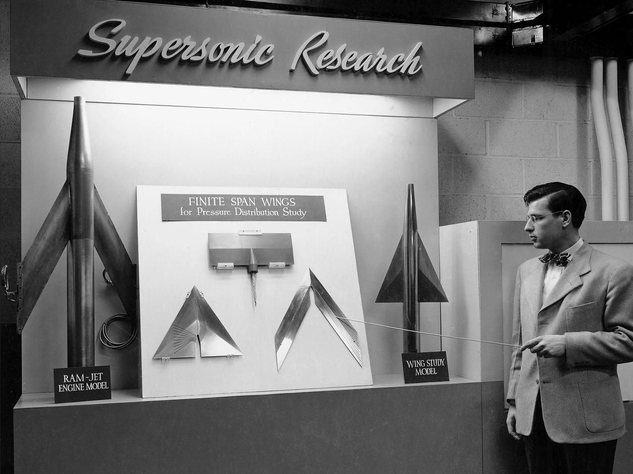
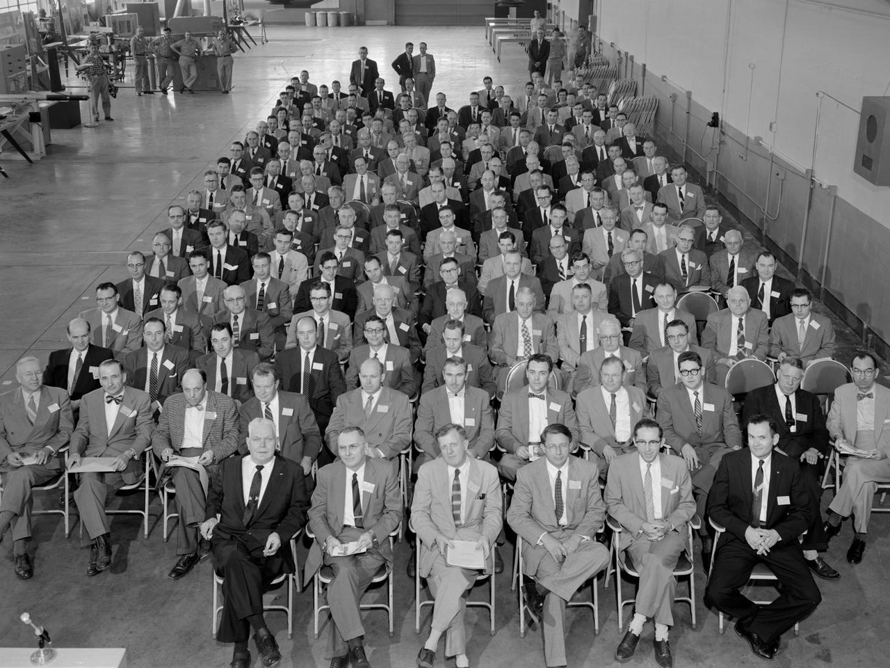
On March 22, 1946, 250 members of the Institute of Aeronautical Science toured the NACA’s Aircraft Engine Research Laboratory. NACA Chairman Jerome Hunsaker and Secretary John Victory were on hand to brief the attendees in the Administration Building before the visited the lab’s test facilities. At each of the twelve stops, researchers provided brief presentations on their work. Topics included axial flow combustors, materials for turbine blades, engine cooling, icing prevention, and supersonic flight. The laboratory reorganized itself in October 1945 as World War II came to an end to address newly emerging technologies such as the jet engine, rockets, and high-speed flight. While design work began on what would eventually become the 8- by 6-Foot Supersonic Wind Tunnel, NACA Lewis quickly built several small supersonic tunnels. These small facilities utilized the Altitude Wind Tunnel’s massive air handling equipment to generate high-speed airflow. The display seen in this photograph was set up in the building that housed the first of these wind tunnels. Eventually the building would contain three small supersonic tunnels, referred to as the “stack tunnels” because of the vertical alignment. The two other tunnels were added to this structure in 1949 and 1951. The small tunnels were used until the early 1960s to study the aerodynamic characteristics of supersonic inlets and exits.
The Fan Noise Test Facility built at the Lewis Research Center to obtain far-field noise data for the National Aeronautics and Space Administration (NASA) and General Electric Quiet Engine Program. The engine incorporated existing noise reduction methods into an engine of similar power to those that propelled the Boeing 707 or McDonnell-Douglas DC-8 airliner. The new the low-bypass ratio turbofan engines of the 1960s were inherently quieter than their turbojet counterparts, researchers had a better grasp of the noise generation problem, and new acoustic technologies had emerged. Lewis contracted General Electric in 1969 to build and aerodynamically test three experimental engines with 72-inch diameter fans. The engines were then brought to Lewis and tested with an acoustically treated nacelle. This Fan Noise Test Facility was built off of the 10- by 10-Foot Supersonic Wind Tunnel’s Main Compressor and Drive Building. Lewis researchers were able to isolate the fan’s noise during these initial tests by removing the core of the engine. The Lewis test rig drove engines to takeoff tip speeds of 1160 feet per second. The facility was later used to test a series of full-scale model fans and fan noise suppressors to be used with the quiet engine. NASA researchers predicted low-speed single-stage fans without inlet guide vanes and with large spacing between rotors and stators would be quieter. General Electric modified a TF39 turbofan engine by removing the the outer protion of the fan and spacing the blade rows of the inner portion. The tests revealed that the untreated version of the engine generated less noise than was anticipated, and the acoustically treated nacelle substantially reduced engine noise.
A Rolls Royce Avon RA-14 engine was tested in the Altitude Wind Tunnel at the National Advisory Committee for Aeronautics’ (NACA) Lewis Flight Propulsion Laboratory. The Avon RA-14 engine was a 16-stage axial-flow compressor turbojet capable of producing 9,500 pounds of thrust. The Avon replaced Rolls Royce’s successful Nene engine in 1950 and remained in service until 1974. It was one of several British engines studied in the tunnel during the 1950s. The Altitude Wind Tunnel went through a series of modifications in 1951 to increase its capabilities. An annex was attached to the Exhauster Building to house three new Ingersoll-Rand compressors. The wooden blades on the tunnel’s 31-foot diameter fan were replaced, a pump house and exhaust cooler were constructed underneath the tunnel, and two new cells were added to the cooling tower. The modified wind tunnel continued to analyze jet engines in the 1950s, although the engines, like the RA-14 seen here, were much more powerful than those studied several years before. Lewis researchers studied the RA-14 turbojet engine in the Altitude Wind Tunnel for 11 months in 1956. The engine was mounted on a stand capable of gauging engine thrust, and the tunnel’s air was ducted to the engine through a venturi and bellmouth inlet, seen in this photograph. The initial studies established the engine’s performance characteristics with a fixed-area nozzle and its acceleration characteristics. The researchers also used the tunnel to investigate windmilling of the compressor blades, restarting at high altitudes, and the engine’s performance limits at altitude.
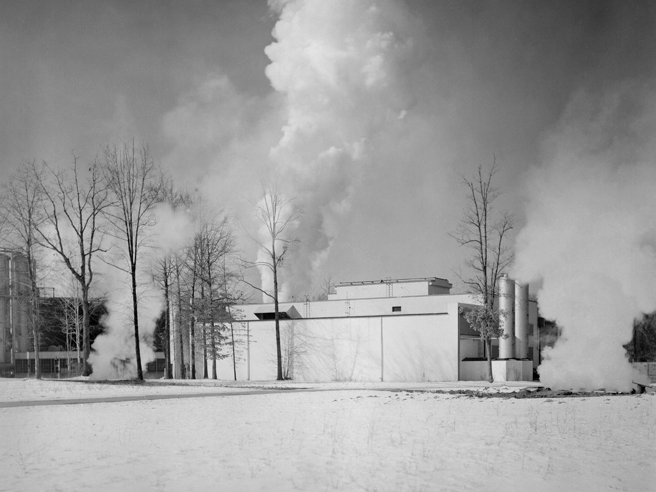
The Engine Propeller Research Building, referred to as the Prop House, emits steam from its acoustic silencers at the National Advisory Committee for Aeronautics (NACA) Lewis Flight Propulsion Laboratory. In 1942 the Prop House became the first completed test facility at the new NACA laboratory in Cleveland, Ohio. It contained four test cells designed to study large reciprocating engines. After World War II, the facility was modified to study turbojet engines. Two of the test cells were divided into smaller test chambers, resulting in a total of six engine stands. During this period the NACA Lewis Materials and Thermodynamics Division used four of the test cells to investigate jet engines constructed with alloys and other high temperature materials. The researchers operated the engines at higher temperatures to study stress, fatigue, rupture, and thermal shock. The Compressor and Turbine Division utilized another test cell to study a NACA-designed compressor installed on a full-scale engine. This design sought to increase engine thrust by increasing its airflow capacity. The higher stage pressure ratio resulted in a reduction of the number of required compressor stages. The last test cell was used at the time by the Engine Research Division to study the effect of high inlet densities on a jet engine. Within a couple years of this photograph the Prop House was significantly altered again. By 1960 the facility was renamed the Electric Propulsion Research Building to better describe its new role in electric propulsion.
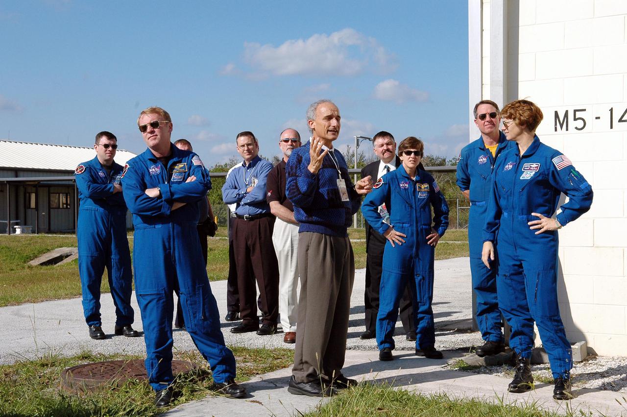
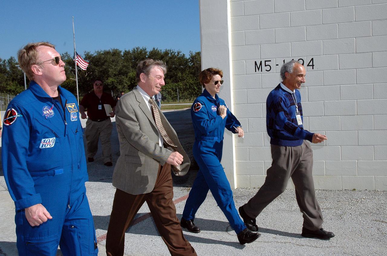
KENNEDY SPACE CENTER, FLA. - During a visit to Kennedy, at the MILA Spaceflight Tracking and Data Network Station, members of the STS-114 crew listen to Gary Morse (center), incumbent MILA_PDL station director. (MILA refers to Merritt Island Launch Area; PDL designates the Ponce De Leon Inlet site.) The astronauts, from left, are Pilot James Kelly, Mission Specialists Andrew Thomas, Wendy Lawrence and Stephen Robinson, and Commander Eileen Collins. The tracking station serves as the primary voice, data and telemetry communications link between the Shuttle and the ground from launch until 7-1_2 minutes into the flight. Millions of clues about the performance of the Space Shuttle’s main engines and other components are communicated to launch managers, technicians and engineers on the ground, who must keep their fingers on the pulse of the Space Shuttle during the critical ascent period. In a typical year, MILA provides through KSC more than 10,000 hours of data between spacecraft and data users. MILA is also used during a Space Shuttle landing at KSC and provides communications beginning about 13 minutes before touchdown. Also, MILA can be called upon to provide data transfer support for NASA’s Expendable Launch Vehicle missions and orbiting scientific satellites.
A .10-scale model of Convair’s XF-102 in the 8- by 6-Foot Supersonic Wind Tunnel at the National Advisory Committee for Aeronautics (NACA) Lewis Flight Propulsion Laboratory for jet exit studies. The XF-102 was a prototype of the F-102 Delta Dagger. The F-102 served as an interceptor against long range bombers from the Soviet Union. The aircraft was powered by a Pratt and Whitney J57 turbojet. The first prototype crashed two weeks after is first flight on October 24, 1953, just months after this photograph. Engineers then incorporated the fixed-wing design to reduce drag at supersonic speeds. The production model F-102 became the first delta-wing supersonic aircraft in operation. The 8- by 6-Foot Supersonic Wind Tunnel is used to study propulsion systems, including inlets and exit nozzles, combustion fuel injectors, flame holders, exit nozzles, and controls on ramjet and turbojet engines. Flexible sidewalls alter the tunnel’s nozzle shape to vary the Mach number during operation. A seven-stage axial compressor, driven by three electric motors that yield a total of 87,000 horsepower, generates air speeds from Mach 0.36 to 2.0.
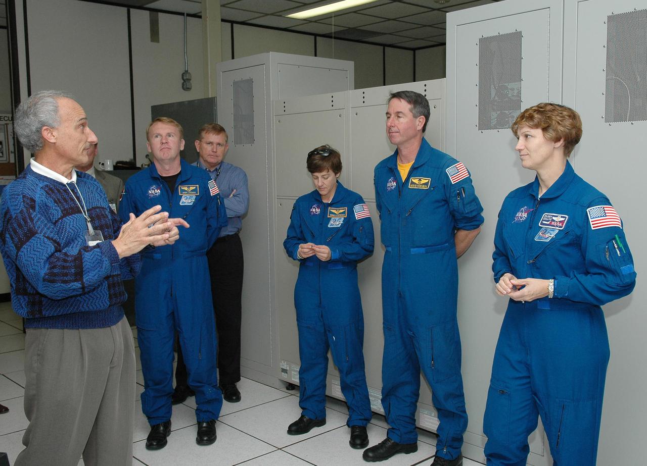
KENNEDY SPACE CENTER, FLA. - Inside the MILA Spaceflight Tracking and Data Network Station during a visit to Kennedy, members of the STS-114 crew listen to Gary Morse (left), incumbent MILA_PDL station director. (MILA refers to Merritt Island Launch Area; PDL designates the Ponce De Leon Inlet site.) The astronauts, from left, are Mission Specialists Andrew Thomas, Wendy Lawrence and Stephen Robinson, and Commander Eileen Collins. The tracking station serves as the primary voice, data and telemetry communications link between the Shuttle and the ground from launch until 7-1_2 minutes into the flight. Millions of clues about the performance of the Space Shuttle’s main engines and other components are communicated to launch managers, technicians and engineers on the ground, who must keep their fingers on the pulse of the Space Shuttle during the critical ascent period. In a typical year, MILA provides through KSC more than 10,000 hours of data between spacecraft and data users. MILA is also used during a Space Shuttle landing at KSC and provides communications beginning about 13 minutes before touchdown. Also, MILA can be called upon to provide data transfer support for NASA’s Expendable Launch Vehicle missions and orbiting scientific satellites.
KENNEDY SPACE CENTER, FLA. - During a visit to Kennedy, members of the STS-114 crew visit the MILA Spaceflight Tracking and Data Network Station. From left are Mission Specialist Andrew Thomas; Anthony Ippolito, current director of MILA_PDL; Commander Eileen Collins; and Gary Morse, incumbent MILA_PDL station director. MILA refers to Merritt Island Launch Area; PDL designates the Ponce De Leon Inlet site. The tracking station serves as the primary voice, data and telemetry communications link between the Shuttle and the ground from launch until 7-1_2 minutes into the flight. Millions of clues about the performance of the Space Shuttle’s main engines and other components are communicated to launch managers, technicians and engineers on the ground, who must keep their fingers on the pulse of the Space Shuttle during the critical ascent period. In a typical year, MILA provides through KSC more than 10,000 hours of data between spacecraft and data users. MILA is also used during a Space Shuttle landing at KSC and provides communications beginning about 13 minutes before touchdown. Also, MILA can be called upon to provide data transfer support for NASA’s Expendable Launch Vehicle missions and orbiting scientific satellites.
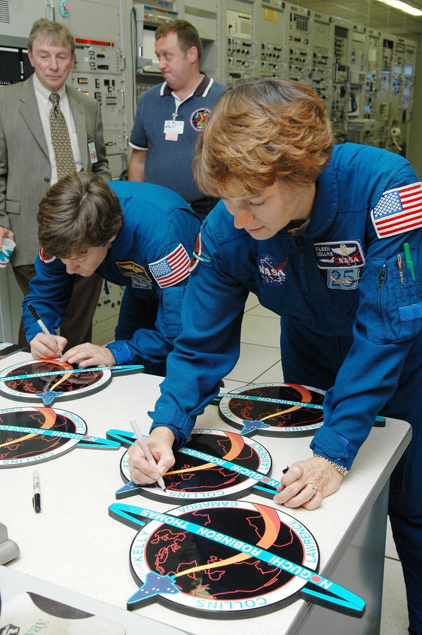
KENNEDY SPACE CENTER, FLA. - Inside the MILA Spaceflight Tracking and Data Network Station during a visit to Kennedy, STS-114 Mission Specialist Wendy Lawrence and Commander Eileen Collins sign crew photos and logos. Behind Lawrence is Anthony Ippolito, current director of MILA_PDL, and William Foster, Johnson Space Center ground controller. (MILA refers to Merritt Island Launch Area; PDL designates the Ponce De Leon Inlet site.) The tracking station serves as the primary voice, data and telemetry communications link between the Shuttle and the ground from launch until 7-1_2 minutes into the flight. Millions of clues about the performance of the Space Shuttle’s main engines and other components are communicated to launch managers, technicians and engineers on the ground, who must keep their fingers on the pulse of the Space Shuttle during the critical ascent period. In a typical year, MILA provides through KSC more than 10,000 hours of data between spacecraft and data users. MILA is also used during a Space Shuttle landing at KSC and provides communications beginning about 13 minutes before touchdown. Also, MILA can be called upon to provide data transfer support for NASA’s Expendable Launch Vehicle missions and orbiting scientific satellites.
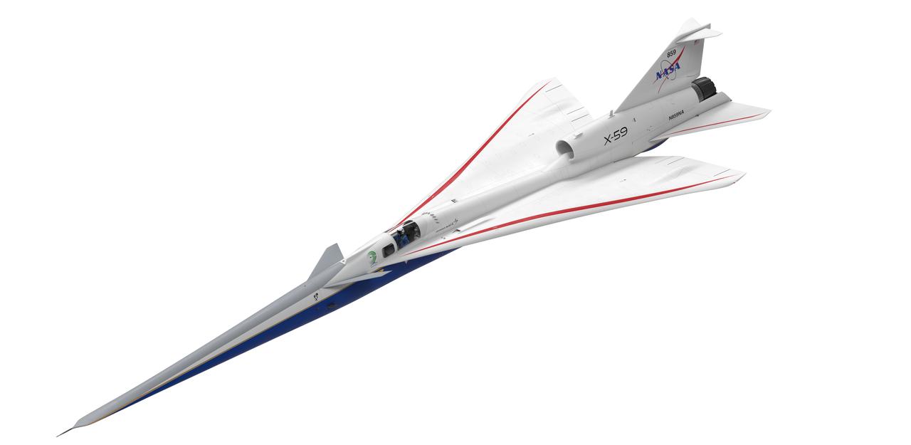
Artist concept of the X-59 three forths view top
The upper empennage, or tail section of the plane, and engine bay is surrounded by a blue gantry that is used to assist with ground installation and removal of the X-59’s lower empennage and engine. Once fully assembled, the X-59 aircraft will demonstrate the ability to fly supersonic while reducing the loud sonic boom to a quiet sonic thump and help enable commercial supersonic air travel over land. This aircraft is the centerpiece of NASA’s Quesst mission.
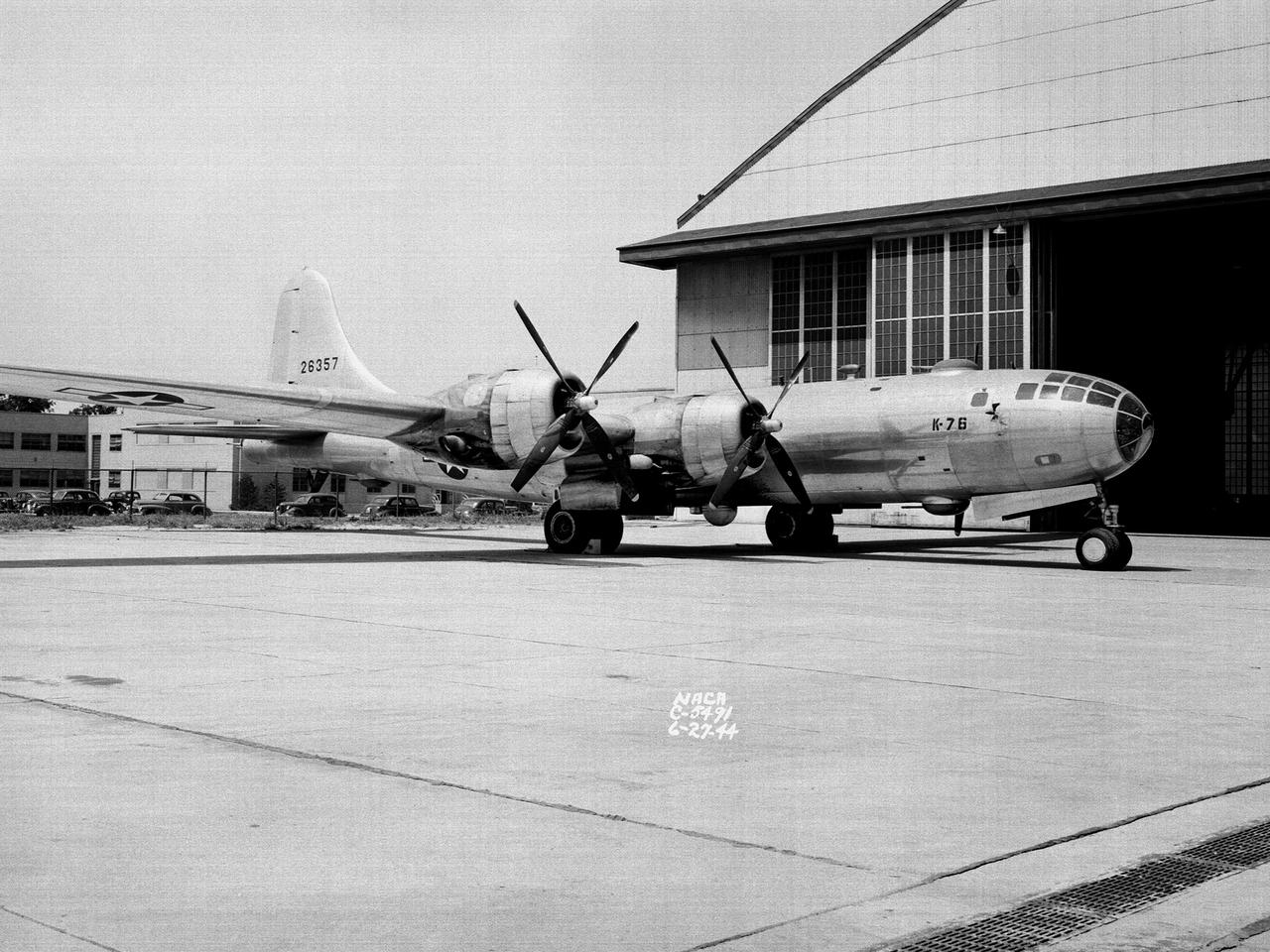
A Boeing B–29 Superfortress at the National Advisory Committee for Aeronautics (NACA) Aircraft Engine Research Laboratory in Cleveland, Ohio. The B–29 was the Army Air Forces’ deadliest weapon during the latter portion of World War II. The aircraft was significantly larger than previous bombers but could fly faster and higher. The B–29 was intended to soar above anti-aircraft fire and make pinpoint drops onto strategic targets. The bomber was forced to carry 20,000 pounds more armament than it was designed for. The extra weight pushed the B–29’s four powerful Wright R–3350 engines to their operating limits. The over-heating of the engines proved to be a dangerous problem. The military asked the NACA to tackle the issue. Full-scale engine tests on a R–3350 engine in the Prop House demonstrated that a NACA-designed impeller increased the flow rate of the fuel injection system. Altitude Wind Tunnel studies of the engine led to the reshaping of cowling inlet and outlet to improve airflow and reduce drag. Single-cylinder studies on valve failures were resolved by a slight extension of the cylinder head, and the Engine Research Building researchers combated uneven heating with a new fuel injection system. The modifications were then tried out on an actual B–29. The bomber arrived in Cleveland on June 22, 1944. The new injection impeller, ducted head baffles and instrumentation were installed on the bomber’s two left wing engines. Eleven test flights were flown over the next month with military pilots at the helm. Overall the flight tests corroborated the wind tunnel and test stand studies.
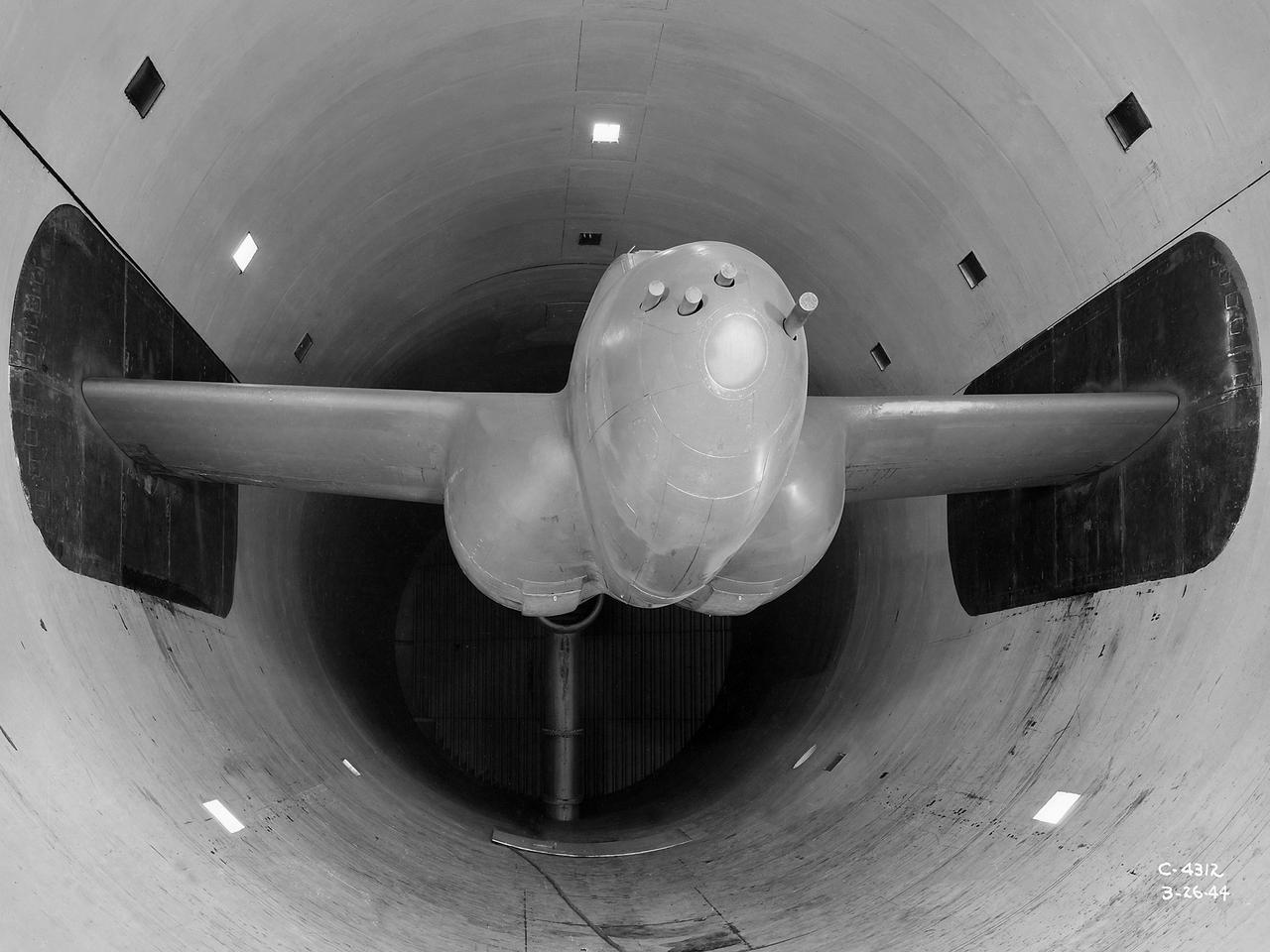
The Altitude Wind Tunnel (AWT) was the National Advisory Committee for Aeronautics (NACA) Aircraft Engine Research Laboratory’s largest and most important test facility in the 1940s. The AWT employed massive cooling and exhaust systems to simulate conditions found at high altitudes. The facility was originally designed to test large piston engines in a simulated flight environment. The introduction of the turbojet during the tunnel’s construction, however, changed the facility’s focus before it became operational. Its first test program was a study of the Bell YP–59A Airacomet and its General Electric I–16 turbojets. The Airacomet was the United States’ first attempt to build a jet aircraft. 1600-horsepower centrifugal engines based on an early design by British engineer Frank Whittle were incorporated into an existing Bell airframe. In October 1942 the Airacomet was secretly test flown in the California desert. The aircraft’s performance was limited, however, and the NACA was asked to study the engines in the AWT. The wind tunnel’s 20-foot-diameter test section was large enough to accommodate entire aircraft with its wing tips and tail removed. The I-16 engines were studied exhaustively in early 1944. They first analyzed the engines in their original configuration and then implemented a boundary layer removal duct, a new nacelle inlet, and new cooling seals. Tests of the modified version showed that the improved distribution of airflow increased the I–16’s performance by 25 percent. The Airacomet never overcame some of its inherent design issues, but the AWT went on to study nearly every emerging US turbojet model during the next decade.
The Aircraft Engine Research Laboratory’s first aircraft, a Martin B–26B Marauder, parked in front of the Flight Research Building in September 1943. The military loaned the B–26B to the National Advisory Committee for Aeronautics (NACA) to augment the lab’s studies of the Wright Aeronautical R–2800 engines. The military wanted to improve the engine cooling in order to increase the bomber’s performance. On March 17, 1943, the B–26B performed the very first research flight at the NACA’s new engine laboratory. The B–26B received its “Widowmaker” nickname during the rushed effort to transition the new aircraft from design to production and into the sky. During World War II, however, the B–26B proved itself to be a capable war machine. The U.S. lost fewer Marauders than any other type of bomber employed in the war. The B–26B was originally utilized at low altitudes in the Pacific but had its most success at high altitudes over Europe. The B–26B’s flight tests in Cleveland during 1943 mapped the R-2800 engine’s behavior at different altitudes and speeds. The researchers were then able to correlate engine performance in ground facilities to expected performance at different altitudes. They found that air speed, cowl flap position, angle of attack, propeller thrust, and propeller speed influenced inlet pressure recovery and exhaust distribution. The flight testing proceeded quickly, and the B–26B was transferred elsewhere in October 1943.
A quality inspector inspects the GE F-414 engine nozzle after installation at Lockheed Martin’s Skunk Works facility in Palmdale, California. Once the aircraft and ground testing are complete, the X-59 will undergo flight testing, which will demonstrate the plane’s ability to fly supersonic - faster than the speed of sound - while reducing the loud sonic boom. This could enable commercial supersonic air travel over land.
A look at the X-59’s engine nozzle, where the thrust -the force that moves the aircraft- will exit. Once complete, the X-59 is designed to fly supersonic while reducing the loud sonic boom. The Quesst mission could help change the rules for commercial supersonic air travel over land.
The secret test of the Bell YP–59A Airacomet in the spring of 1944 was the first investigation in the National Advisory Committee for Aeronautics (NACA) Aircraft Engine Research Laboratory’s new Altitude Wind Tunnel (AWT). The Airacomet, powered by two General Electric I–A centrifugal turbojets, was the first US jet aircraft. The Airacomet’s 290-miles per hour speed, however, was dwarfed by the German Messerschmitt Me-262 Schwalbe’s 540 miles per hour. In 1941 and 1942 General Electric built the first US jet engines based on technical drawings from British engineer Frank Whittle. Bell Aircraft was contracted to produce an airframe to incorporate the new engines. The result was the Bell XP–59A Airacomet. The aircraft made its first flight over Muroc Lake, California, on October 2, 1942. The aircraft continued to struggle over the next year and the NACA was asked to test it in the new AWT. A Bell YP–59A was flown from the Bell plant in Buffalo to Cleveland by Bob Stanley, who had piloted the first successful flight of the XP–59A at Muroc in 1942. The wing tips and tail were cut from the aircraft so that it would fit into the AWT’s test section. The study first analyzed the engines in their original configuration and then implemented a boundary layer removal duct, a new nacelle inlet, and new cooling seals. Tests of the modified version showed that the improved airflow distribution increased the I–16’s performance by 25 percent. Despite the improved speed, the aircraft was not stable enough to be used in combat, and the design was soon abandoned.
National Aeronautics and Space Administration (NASA) Convair F-106B Delta Dart with a 32-spoke nozzle installed on its General Electric J85 test engine. Lewis acquired a Delta Dart fighter in 1966 to study the components for propulsion systems that could be applied to supersonic transport aircraft at transonic speeds. The F-106B was modified with two General Electric J85-13 engines under its wings to study these components. The original test plan was expanded to include the study of boattail drag, noise reduction, and inlets. From February to July 1971 the modified F-106B was used to study different ejector nozzles. Researchers conducted both acoustic and aerodynamic tests on the ground and in flight. Several models were created to test different suppression methods. NASA Lewis’ conical nozzle was used as the baseline configuration. Flightline and sideline microphones were set up on the ground. The F-106B would idle its own engine and buzz the recording station from an altitude of 300 feet at Mach 0.4 with the test engines firing. Researchers found that the suppression of the perceived noise level was usually lower during flight than the researchers had statistically predicted. The 64 and 32-spoke nozzles performed well in actual flight, but the others nozzles tended to negatively affect the engine’s performance. Different speeds or angles- -of-attack sometimes changed the noise levels. In the end, no general conclusions could be applied to all the nozzles.
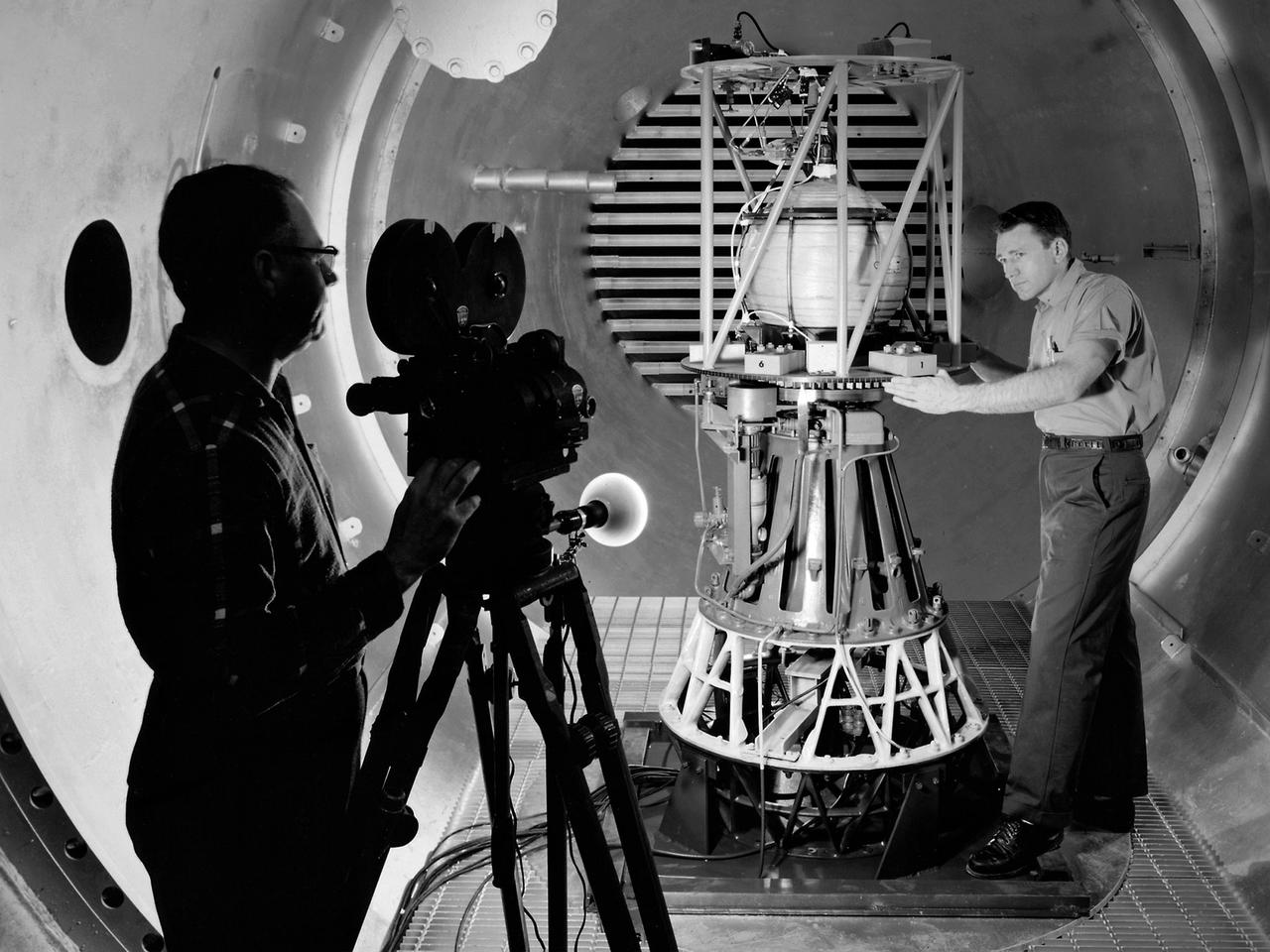
Mechanic Howard Wine inspects the setup of a spin isolator in Cell 2 of the Propulsion Systems Laboratory at the National Aeronautics and Space Administration (NASA) Lewis Research Center. Photographer Al Jecko filmed the proceedings. This test was unique in that the chamber’s altitude system was used, but not its inlet air flow. The test was in preparation for an upcoming launch of modified liquid hydrogen propellant tank on a sounding rocket. This Weightlessness Analysis Sounding Probe (WASP) was part of Lewis investigation into methods for controlling partially filled liquid hydrogen fuel tanks during flight. Second-stage rockets, the Centaur in particular, were designed to stop their engines and coast, then restart them when needed. During this coast period, the propellant often shifted inside the tank. This movement could throw the rocket off course or result in the sloshing of fuel away from the fuel pump. Wine was one of only three journeymen mechanics at Lewis when he was hired in January 1954. He spent his first decade in the Propulsion Systems Laboratory and was soon named a section head. Wine went on to serve as Assistant Division Chief and later served as an assistant to the director. Jecko joined the center in 1947 as a photographer and artist. He studied at the Cleveland School or Art and was known for his cartoon drawing. He worked at the center for 26 years.
Aerial view of the 8- by 6-Foot Supersonic Wind Tunnel in its original configuration at the National Advisory Committee for Aeronautics (NACA) Lewis Flight Propulsion Laboratory. The 8- by 6 was the laboratory’s first large supersonic wind tunnel. It was also the NACA’s most powerful supersonic tunnel, and its first facility capable of running an engine at supersonic speeds. The 8- by 6-foot tunnel has been used to study inlets and exit nozzles, fuel injectors, flameholders, exit nozzles, and controls on ramjet and turbojet propulsion systems. The 8- by 6 was originally an open-throat and non-return tunnel. This meant that the supersonic air flow was blown through the test section and out the other end into the atmosphere. In this photograph, the three drive motors in the structure at the left supplied power to the seven-stage axial-flow compressor in the light-colored structure. The air flow passed through flexible walls which were bent to create the desired speed. The test article was located in the 8- by 6-foot stainless steel test section located inside the steel pressure chamber at the center of this photograph. The tunnel dimensions were then gradually increased to slow the air flow before it exited into the atmosphere. The large two-story building in front of the tunnel was used as office space for the researchers.
The 8- by 6-Foot Supersonic Wind Tunnel at the National Advisory Committee for Aeronautics (NACA) Lewis Flight Propulsion Laboratory was the nation’s largest supersonic facility when it began operation in April 1949. The emergence of new propulsion technologies such as turbojets, ramjets, and rockets during World War II forced the NACA and the aircraft industry to develop new research tools. In late 1945 the NACA began design work for new large supersonic wind tunnels at its three laboratories. The result was the 4- by 4-Foot Supersonic Wind Tunnel at Langley Memorial Aeronautical Laboratory, 6- by 6-foot supersonic wind tunnel at Ames Aeronautical Laboratory, and the largest facility, the 8- by 6-Foot Supersonic Wind Tunnel in Cleveland. The two former tunnels were to study aerodynamics, while the 8- by 6 facility was designed for supersonic propulsion. The 8- by 6-Foot Supersonic Wind Tunnel was used to study propulsion systems, including inlets and exit nozzles, combustion fuel injectors, flame holders, exit nozzles, and controls on ramjet and turbojet engines. Flexible sidewalls alter the tunnel’s nozzle shape to vary the Mach number during operation. A seven-stage axial compressor, driven by three electric motors that yield a total of 87,000 horsepower, generates air speeds from Mach 0.36 to 2.0. A section of the tunnel is seen being erected in this photograph.
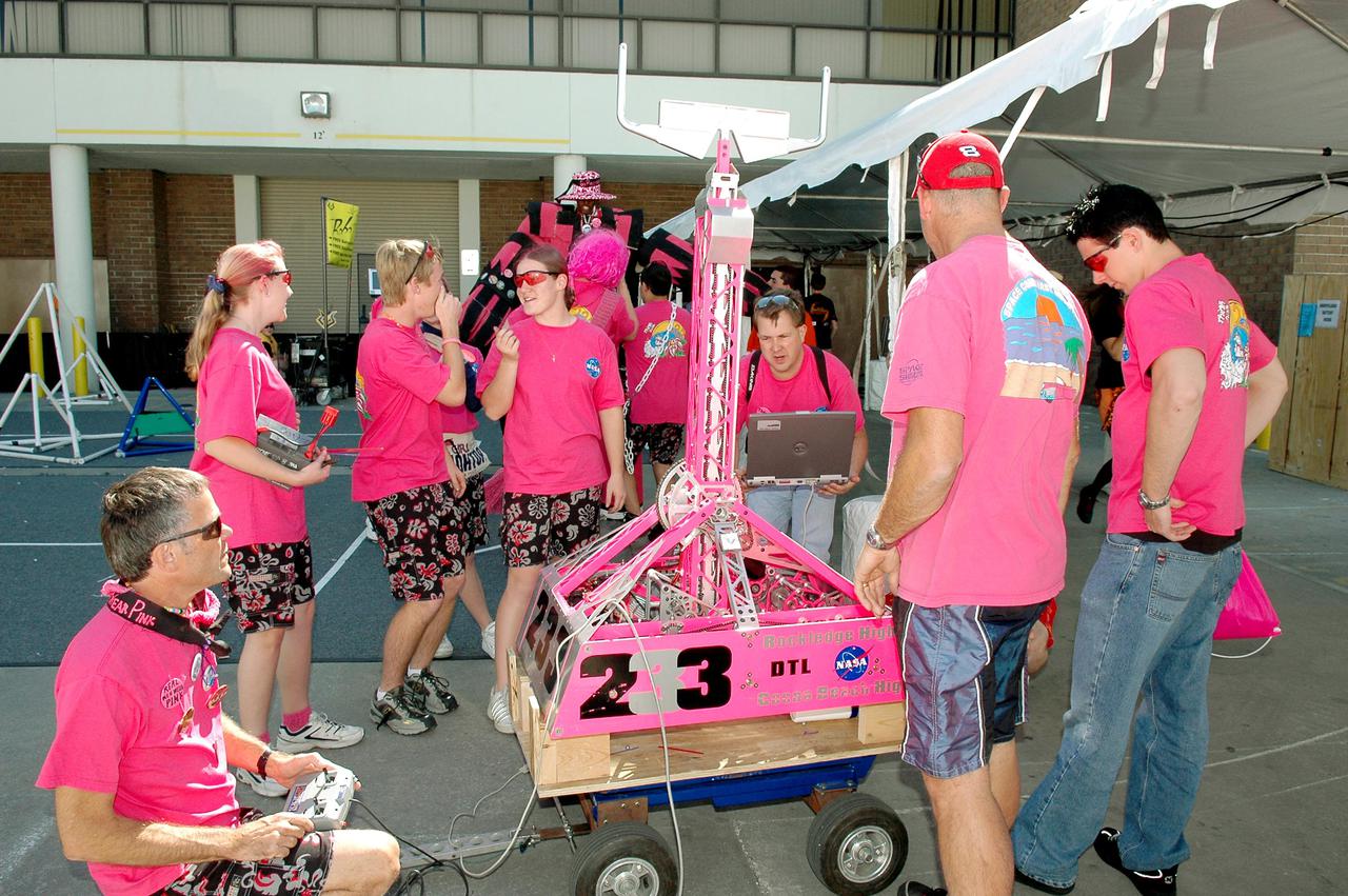
KENNEDY SPACE CENTER, FLA. - Members of the NASA-sponsored Space Coast FIRST Robotics Team, known as the Pink Team, prepare to compete with their robot, Roccobot. The competition was part of the 2005 FIRST Robotics Regional Competition held at the University of Central Florida March 10-12, 2005. The Pink Team took first place in the competition as part of the three-team winning alliance and advances to the Championship in Atlanta in April. The Pink Team comprises students from Rockledge High School and Cocoa Beach Junior_Senior High School, and was joined by the Bionic Tigers from Cocoa High School, sponsored by Analex Corp., and Children of the Swamp from Inlet Grove Community High School in West Palm Beach, sponsored by UTC-Pratt and Whitney-SP. NASA and the University of Central Florida are co-hosts of the regional event. The competition stages short games played by remote-controlled robots, which are designed and built in six weeks by a team of high school students and a handful of engineers-mentors. The students control the robots on the playing field.
NASA’s X-59 sits in support framing while undergoing the installation of its lower empennage, or tail section, at Lockheed Martin Skunk Works in Palmdale, California in late March.
The tail of NASA’s X-59 aircraft is shown here in late March at Lockheed Martin Skunk Works in Palmdale, California where the plane recently underwent a final install of the lower empennage or better known as tail section of the plane.
A Bell P-39 Airacobra in the NACA Aircraft Engine Research Laboratory’s Icing Research Tunnel for a propeller deicing study. The tunnel, which began operation in June 1944, was built to study the formation of ice on aircraft surfaces and methods of preventing or eradicating that ice. Ice buildup adds extra weight to aircraft, effects aerodynamics, and sometimes blocks airflow through engines. NACA design engineers added the Icing Research Tunnel to the new AERL’s original layout to take advantage of the massive refrigeration system being constructed for the Altitude Wind Tunnel. The Icing Research Tunnel is a closed-loop atmospheric wind tunnel with a 6- by 9-foot test section. The tunnel can produce speeds up to 300 miles per hour and temperatures from about 30 to -45⁰ F. During World War II AERL researchers analyzed different ice protection systems for propeller, engine inlets, antennae, and wings in the icing tunnel. The P-39 was a vital low-altitude pursuit aircraft of the US during the war. NACA investigators investigated several methods of preventing ice buildup on the P-39’s propeller, including the use of internal and external electrical heaters, alcohol, and hot gases. They found that continual heating of the blades expended more energy than the aircraft could supply, so studies focused on intermittent heating. The results of the wind tunnel investigations were then compared to actual flight tests on aircraft.
A researcher examines a model being installed in the test section of the 10- by 10-Foot Supersonic Wind Tunnel during the 1957 Inspection of the National Advisory Committee for Aeronautics (NACA) Lewis Flight Propulsion Laboratory. The NACA held its annual Inspection at one of its three research laboratories. Representatives from the military, aeronautical industry, universities, and the press were invited to the laboratory to be briefed on the NACA’s latest research efforts and tour the state- of- the- art test facilities. Over 1700 people visited the NACA Lewis in Cleveland, Ohio during the October 7 - 10, 1957 Inspection. NACA researchers Leonard Obery, seen here, James Connors, Leonard, Stitt, David Bowditch gave presentations on high Mach number turbojets at the 10- by 10 tunnel. It had been only 15 years since a jet aircraft had first flown in the US. Since then the sound barrier had been broken and speeds of Mach 2.5 had been achieved. In the late 1950s NACA researchers sought to create an engine that could achieve Mach 4. This type of engine would require an extremely long inlet and nozzle which would have to be capable of adjusting their diameter for different speeds. A Mach 4 engine would require new composite materials to withstand the severe conditions, modified airframes to hold the longer engines, and high temperature seals and lubricants. The 10- by 10-foot tunnel, which had only been in operation for a year and a half, would play a critical role in these studies. NACA researchers at other facilities discussed high energy aircraft fuels and rocket propellants, aircraft noise reduction, hypersonic flight, nuclear propulsion, and high temperature materials.
A Bell P-39 Airacobra in the NACA Aircraft Engine Research Laboratory’s Icing Research Tunnel for a propeller deicing study. The tunnel, which began operation in June 1944, was built to study the formation of ice on aircraft surfaces and methods of preventing or eradicating that ice. Ice buildup adds extra weight to aircraft, effects aerodynamics, and sometimes blocks airflow through engines. NACA design engineers added the Icing Research Tunnel to the new AERL’s original layout to take advantage of the massive refrigeration system being constructed for the Altitude Wind Tunnel. The Icing Research Tunnel is a closed-loop atmospheric wind tunnel with a 6- by 9-foot test section. The tunnel can produce speeds up to 300 miles per hour and temperatures from about 30 to –45⁰ F. During World War II AERL researchers analyzed different ice protection systems for propeller, engine inlets, antennae, and wings in the icing tunnel. The P-39 was a vital low-altitude pursuit aircraft of the US during the war. NACA investigators investigated several methods of preventing ice buildup on the P-39’s propeller, including the use of internal and external electrical heaters, alcohol, and hot gases. They found that continual heating of the blades expended more energy than the aircraft could supply, so studies focused on intermittent heating. The results of the wind tunnel investigations were then compared to actual flight tests on aircraft.
The NACA’s Lewis Flight Propulsion Laboratory used a Boeing B-29 Superfortress as a testbed for ramjet investigations in the late 1940s. NACA Lewis conducted a wide variety of studies on ramjets to determine basic operational data necessary to design missiles. This information included the relationship between combustion chamber and inlet pressure and temperature, velocity of the fuel-air ratio to the ignition characteristics, and combustion efficiency. Although wind tunnel and test stand studies were important first steps in determining these factors, actual flight tests were required. Lewis engineers modified the B-29 so that the ramjet could be stored in the bomb bay. Once the aircraft reached the desired altitude and speed the ramjet was suspended 52 inches below the bomb bay. The ramjet’s angle-of-attack could be independently adjusted, and a periscope permitted a view of the test article from inside the aircraft. Measurements were taken in free-stream conditions between 5,000 and 30,000 feet. The test flights, which began in April 1947, were flown at speeds up to Mach 0.51 and altitudes of 5,000 to 30,000 feet. The researchers first determined that 14,000 feet was the maximum altitude at which the engine could be ignited by spark. Flares were used to start the engine at altitudes up to 30,000 feet. Overall the ramjet operated well at all speeds and altitudes. Significant changes in fuel flow were successful at lower altitudes, but produced combustion blowout above 20,000 feet.
A researcher at the National Advisory Committee for Aeronautics (NACA) Lewis Flight Propulsion Laboratory checks the setup of a RJM-2 ramjet model in the test section of the 8- by 6-Foot Supersonic Wind Tunnel. The 8- by 6 was not only the laboratory’s first large supersonic wind tunnel, but it was also the NACA’s first facility capable of testing an operating engine at supersonic speeds. The 8- by 6-foot tunnel has been used to study engine inlets, fuel injectors, flameholders, exit nozzles, and controls on ramjet and turbojet propulsion systems. The 8-foot wide and 6-foot tall test section consisted of 1-inch thick steel plates with hatches on the floor and ceiling to facilitate the installation of the test article. The two windows seen on the right wall allowed photographic equipment to be set up. The test section was modified in 1956 to accommodate transonic research. NACA engineers drilled 4,700 holes into the test section walls to reduce transonic pressure disturbances and shock waves. NACA Lewis undertook an extensive research program on ramjets in the 1940s using several of its facilities. Ramjets provide a very simple source of propulsion. They are basically a tube which ingests high speed air, ignites it, and then expels the heated air at a significantly higher velocity. Ramjets are extremely efficient and powerful but can only operate at high speeds. Therefore, they require a booster rocket or aircraft drop to accelerate them to high speeds before they can operate.
Attendees listen during the May 22, 1956 Inspection of the new 10- by 10-Foot Supersonic Wind Tunnel at the National Advisory Committee for Aeronautics (NACA) Lewis Flight Propulsion Laboratory. The facility, known at the time as the Lewis Unitary Plan Tunnel, was in its initial stages of operation. The $33 million 10- by 10 was the most powerful wind tunnel in the nation. Over 150 guests from industry, other NACA laboratories, and the media attended the event. The speakers, from left to right in the front row, addressed the crowd before the tour. Lewis Director Raymond Sharp began the event by welcoming the visitors to the laboratory. NACA Director Hugh Dryden discussed Congress’ Unitary Plan Act and its effect on the creation of the facility. Lewis Associate Director Abe Silverstein discussed the need for research tools and the 10- by 10’s place among the NACA’s other research facilities. Lewis Assistant Director Eugene Wasielewski described the detailed design work that went into the facility. Carl Schueller, Chief of the 10- by 10, described the tunnel’s components and how the facility operated. Robert Godman led the tour afterwards. The 10- by 10 can test engines up to five feet in diameter at supersonic speeds and simulated altitudes of 30 miles. Its main purpose is to investigate problems relating to engine inlet and outlet geometry, engine matching and interference effects, and overall drag. The tunnel’s 250,000-horsepower electric motor drive, the most powerful of its kind in the world, creates air speeds between Mach 2.0 and 3.5.

National Aeronautics and Space Administration (NASA) researcher John Carpenter inspects an aircraft model with a four-fan thrust reverser which would be studied in the 9- by 15-Foot Low Speed Wind Tunnel at the Lewis Research Center. Thrust reversers were introduced in the 1950s as a means for slowing high-speed jet aircraft during landing. Engineers sought to apply the technology to Vertical and Short Takeoff and Landing (VSTOL) aircraft in the 1970s. The new designs would have to take into account shorter landing areas, noise levels, and decreased thrust levels. A balance was needed between the thrust reverser’s efficiency, its noise generation, and the engine’s power setting. This model underwent a series of four tests in the 9- by 15-foot tunnel during April and May 1974. The model, with a high-wing configuration and no tail, was equipped with four thrust-reverser engines. The investigations included static internal aerodynamic tests on a single fan/reverser, wind tunnel isolated fan/reverser thrust tests, installation effects on a four-fan airplane model in a wind tunnel, and single reverser acoustic tests. The 9-by 15 was built inside the return leg of the 8- by 6-Foot Supersonic Wind Tunnel in 1968. The facility generates airspeeds from 0 to 175 miles per hour to evaluate the aerodynamic performance and acoustic characteristics of nozzles, inlets, and propellers, and investigate hot gas re-ingestion of advanced VSTOL concepts. John Carpenter was a technician in the Wind Tunnels Service Section of the Test Installations Division.
This is an overhead view of the X-59 aircraft at Lockheed Martin Skunk Works in Palmdale, California. The nose was installed, and the plane awaits engine installation. Technicians continue to wire the aircraft as the team preforms several system checkouts to ensure the safety of the aircraft. The X-59 aircraft will demonstrate the ability to fly supersonic while reducing the loud sonic boom to a quiet sonic thump and help enable commercial supersonic air travel over land.
KENNEDY SPACE CENTER, FLA. - Outside the MILA Spaceflight Tracking and Data Network Station during a visit to Kennedy, members of the STS-114 crew pause for a photo with Anthony Ippolito (far left), current director of MILA_PDL. (MILA refers to Merritt Island Launch Area; PDL designates the Ponce De Leon Inlet site.). The crew members are (left to right) commander Eileen Collins, Mission Specialists Stephen Robinson, Wendy Lawrence and Andrew Thomas; and Pilot James Kelly. Between Lawrence and Thomas is Gary Morse (left), incumbent MILA_PDL station director. Between Thomas and Kelly is Melissa Blizzard, MILA operations manager. The tracking station serves as the primary voice, data and telemetry communications link between the Shuttle and the ground from launch until 7-1_2 minutes into the flight. Millions of clues about the performance of the Space Shuttle’s main engines and other components are communicated to launch managers, technicians and engineers on the ground, who must keep their fingers on the pulse of the Space Shuttle during the critical ascent period. In a typical year, MILA provides through KSC more than 10,000 hours of data between spacecraft and data users. MILA is also used during a Space Shuttle landing at KSC and provides communications beginning about 13 minutes before touchdown. Also, MILA can be called upon to provide data transfer support for NASA’s Expendable Launch Vehicle missions and orbiting scientific satellites.
National Aeronautics and Space Administration (NASA) researchers install a small-scale model of the capsule for Project Mercury in the 1- by 1-Foot Supersonic Wind Tunnel at the Lewis Research Center. NASA Lewis conducted a variety of tests for Project Mercury, including retrorocket calibration, escape tower engine performance, and separation of the capsule from simulated Atlas and Redstone boosters. The test of this capsule and escape tower model in the 1- by 1-foot tunnel were run in January and February 1960. The 1-by 1-Foot Supersonic Wind Tunnel had a 15-inch long test section, seen here, that was one foot wide and one foot high. The sides were made of glass to allow cameras to capture the supersonic air flow over the models. The tunnel could generate air flows from Mach 1.3 to 3.0. At the time, it was one of nine small supersonic wind tunnels at Lewis. These tunnels used the exhauster and compressor equipment of the larger facilities. The 1- by 1 tunnel, which began operating in the early 1950s, was built inside a test cell in the expansive Engine Research Building. During the 1950s the 1- by 1 was used to study a variety of inlets, nozzles, and cones for missiles and scramjets. The Mercury capsule tests were among the last at the facility for many years. The tunnel was mothballed in 1960. The 1- by 1 was briefly restored in 1972, then brought back online for good in 1979. The facility has maintained a brisk operating schedule ever since.

ISS024-E-010403 (31 July 2010) --- This detailed image ? photographed by an Expedition 24 crew member on the International Space Station (ISS) ? is centered on the NASA Lyndon B. Johnson Space Center (JSC), located in the southeastern Houston, TX metropolitan area. While initially being represented by a number of temporary locations in Houston, the facility was established in 1961 as the Manned Spacecraft Center and renamed in honor of the late U.S. President Johnson (a Texas native) in 1973. JSC serves as the lead NASA center for both astronaut training and mission control of manned spacecraft - such as the ISS and space shuttle - and has done so throughout the history of the U.S. manned space program. The Center also collaborates with other NASA and international partner facilities in a variety of scientific and engineering programs related to human spaceflight and planetary exploration. JSC is located approximately midway between downtown Houston and Galveston, TX, and is bordered by several smaller municipalities that form a mosaic of urban and suburban land use (grey areas with street grids, and commercial/industrial areas characterized by white rooftops). Large tracts of grassy fields and forests in the area (light to dark green respectively) include nature preserves, grazing lands, and flood control areas. Also visible at upper left is Ellington Field. This airport services a variety of NASA aircraft used for astronaut training, scientific, and cargo transport purposes. Clear Lake, an inlet of Galveston Bay, is located to the immediate southeast of JSC. Both Clear Lake and Galveston Bay appear silver-grey due to sunglint, or light reflected back towards the observer on the ISS that gives the water surface a mirror-like appearance. Several boat wakes are visible in Galveston Bay (right) due to disruption of the water surface that reduces the sunglint effect.
Engineers calibrate one of three small supersonic wind tunnels that were collectively referred to as the “Stack Tunnels” at the National Advisory Committee for Aeronautics (NACA) Lewis Flight Propulsion Laboratory. In late 1945 NACA Lewis reorganized its staff and began constructing a new wave of facilities to address high-speed flight and the turbojet and rocket technologies that emerged during World War II. While design work began on what would eventually become the 8- by 6-Foot Supersonic Wind Tunnel, NACA Lewis quickly built several small supersonic tunnels. These small facilities utilized the Altitude Wind Tunnel’s massive air handling equipment. Three of the small tunnels were built vertically on top of each other and thus were known as the Stack Tunnels. The first of the Stack Tunnels was an 18- by 18-inch tunnel that began operating in August 1945 at speeds up to Mach 1.91. The second tunnel, whose 24- by 24-inch test section is shown here, was added in 1949. It could generate air flows up to Mach 3.96. A third tunnel with an 18- by 18-inch test section began operating in 1951 with speeds up to Mach 3.05. The small tunnels were used until the early 1960s to study the aerodynamic characteristics of supersonic inlets and exits. The technician to the left in this photograph is operating a Schlieren camera to view the air flow dynamics inside the 24- by 24-inch test section. The technician on the right is viewing the pronged test article through the circular window. They are calibrating the tunnel and its equipment to prepare for the initial test runs.
Technicians perform landing gear checkout testing at Lockheed Martin Skunk Works in Palmdale, California. These tests make sure that all the parts of X-59’s landing gear and doors are working in the correct order. The X-59 is the centerpiece of NASA’s Quesst mission, which could help enable commercial supersonic air travel over land.
A laser scans the inside of the X-59 aircraft’s lower engine bay at Lockheed Martin Skunk Works in Palmdale, California. These scans can help identify potential hardware or wiring interferences prior to the final installation of the engine and lower tail.