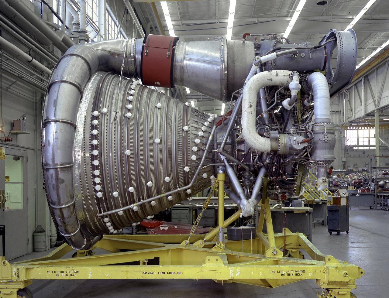
A complete F-1 engine assembly is shown in this photograph. Designed and developed by Rocketdye under the direction of the Marshall Space Flight Center, the engine measured 19-feet tall by 12.5 feet at the nozzle exit, and each engine produced a 1,500,000-pound thrust using liquid oxygen and kerosene as the propellant. A cluster of five F-1 engines was mounted on the Saturn V S-IC (first) stage and burned 15 tons of liquid oxygen and kerosene each second to produce 7,500,000 pounds of thrust.
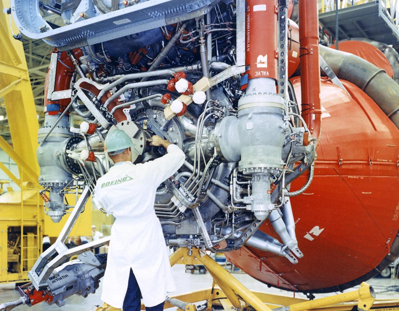
This image depicts a Boeing worker installing an F-1 engine on the Saturn V S-IC flight stage at the Michoud Assembly Facility (MAF). The Saturn IB and Saturn V first stages were manufactured at the MAF, located 24 kilometers (approximately 15 miles) east of downtown New Orleans, Louisiana. The prime contractors, Chrysler and Boeing, jointly occupied the MAF. The basic manufacturing building boasted 43 acres under one roof. By 1964, NASA added a separate engineering and office building, vertical assembly building, and test stage building.
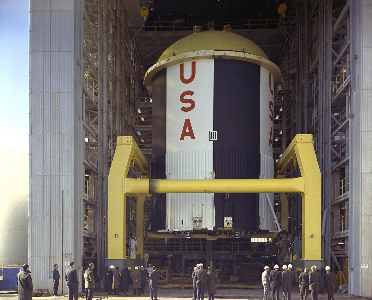
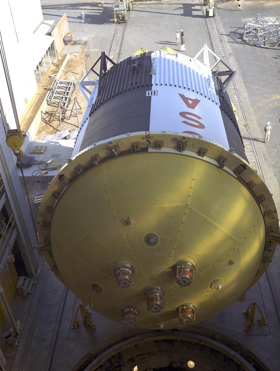
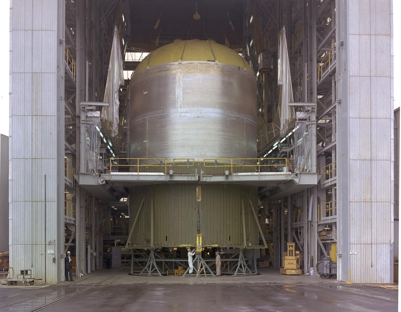
The fuel tank assembly of the Saturn V S-IC (first) stage supported with the aid of a C frame on the transporter was readied to be transported to the Marshall Space Flight Center, building 4705. The fuel tank carried kerosene (RP-1) as its fuel. The S-IC stage utilized five F-1 engines that used kerosene and liquid oxygen as propellant and each engine provided 1,500,000 pounds of thrust. This stage lifted the entire vehicle and Apollo spacecraft from the launch pad.
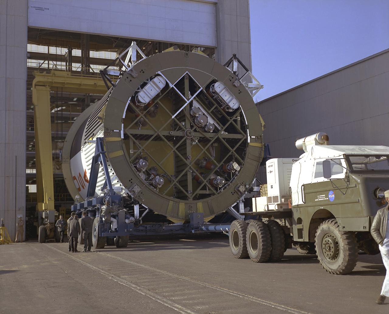
This photograph shows the fuel tank assembly for the Saturn V S-IC (first) stage being transported to the Marshall Space Flight Center, building 4705 for mating to the liquid oxygen (LOX) tank. The fuel tank carried kerosene (RP-1) as its fuel. The S-IC stage used five F-1 engines, that used kerosene and liquid oxygen as propellant and each engine provided 1,500,000 pounds of thrust. This stage lifted the entire vehicle and Apollo spacecraft from the launch pad.
The fuel tank assembly of the Saturn V S-IC (first) stage is readied to be mated to the liquid oxygen tank at the Marshall Space Flight Center. The fuel tank carried kerosene as its fuel. The S-IC stage utilized five F-1 engines that used kerosene and liquid oxygen as propellant. Each engine provided 1,500,000 pounds of thrust. This stage lifted the entire vehicle and Apollo spacecraft from the launch pad.
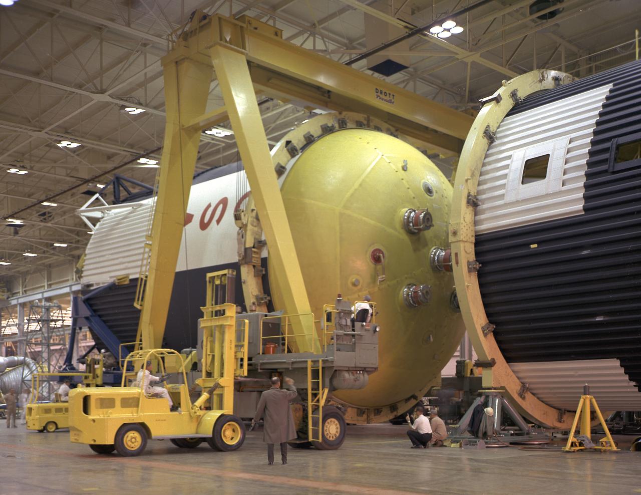
This photograph shows how the fuel tank assembly and the liquid oxygen tank for the Saturn V S-IC (first) stage are placed side by side prior to commencement of the mating of the two stages in the Marshall Space Flight Center, building 4705. The fuel tank carried kerosene as its fuel. The S-IC stage used five F-1 engines, that used kerosene and liquid oxygen as propellant and each engine provided 1,500,000 pounds of thrust. This stage lifted the entire vehicle and Apollo spacecraft from the launch pad.
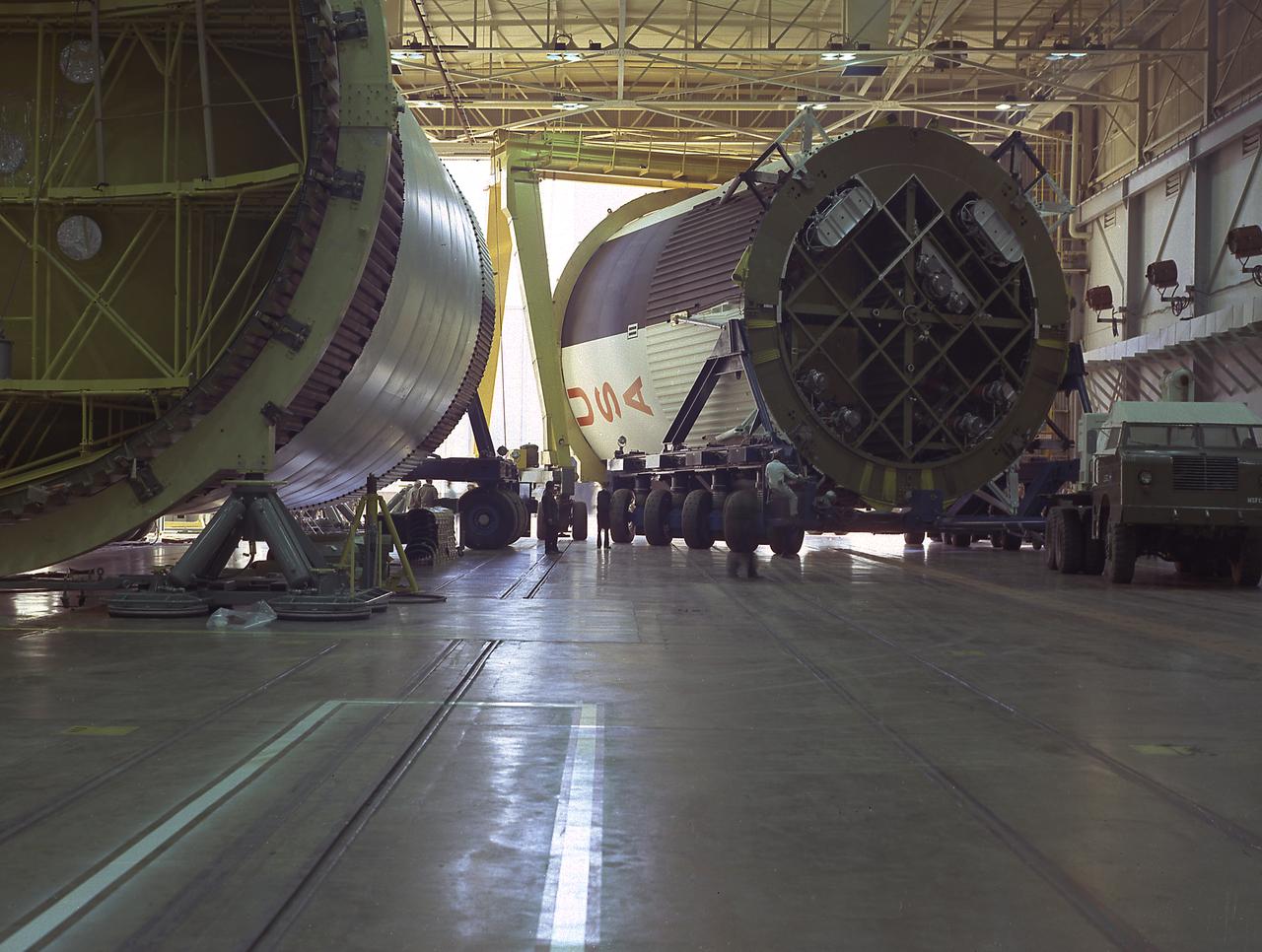
The fuel tank assembly for the Saturn V S-IC (first) stage arrived at the Marshall Space Flight Center, building 4707, for mating to the liquid oxygen tank. The fuel tank carried kerosene as its fuel. The S-IC stage used five F-1 engines, that used kerosene and liquid oxygen as propellant and each engine provided 1,500,000 pounds of thrust. This stage lifted the entire vehicle and Apollo spacecraft from the launch pad.
At the Marshall Space Flight Center (MSFC), the fuel tank assembly for the Saturn V S-IC-T (static test stage) fuel tank assembly is mated to the liquid oxygen (LOX) tank in building 4705. This stage underwent numerous static firings at the newly-built S-IC Static Test Stand at the MSFC west test area. The S-IC (first) stage used five F-1 engines that produced a total thrust of 7,500,000 pounds as each engine produced 1,500,000 pounds of thrust. The S-IC stage lifted the Saturn V vehicle and Apollo spacecraft from the launch pad.
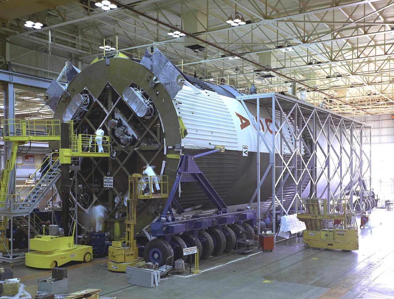
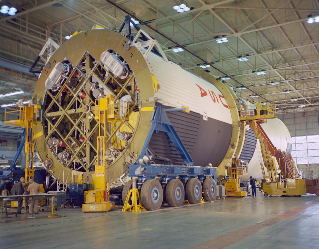
Pictured is the Saturn V S-IC-T stage (static testing stage) being assembled in the horizontal assembly station at the Marshall Space Flight Center (MSFC), building 4705. This stage underwent numerous static firings at the newly-built S-IC Static Test Stand at the MSFC west test area. The S-IC (first) stage used five F-1 engines that produced a total thrust of 7,500,000 pounds as each engine produced 1,500,000 pounds of thrust. The S-IC stage lifted the Saturn V vehicle and Apollo spacecraft from the launch pad.
This image shows the Saturn V S-IC-T stage (S-IC static test article) fuel tank being attached to the thrust structure in the vehicle assembly building at the Marshall Space Flight Center (MSFC). The S-IC stage utilized five F-1 engines that used liquid oxygen and kerosene as propellant and provided a combined thrust of 7,500,000 pounds.
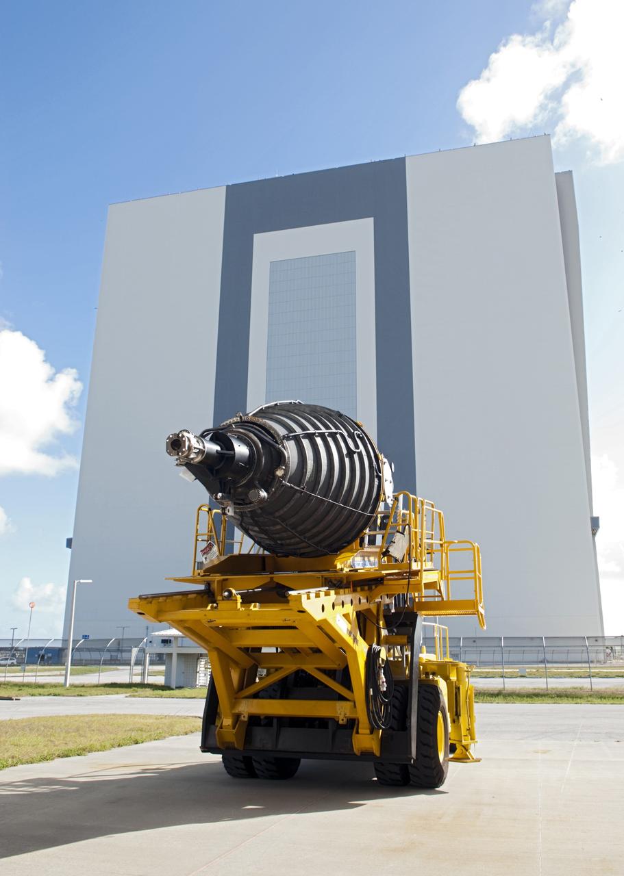
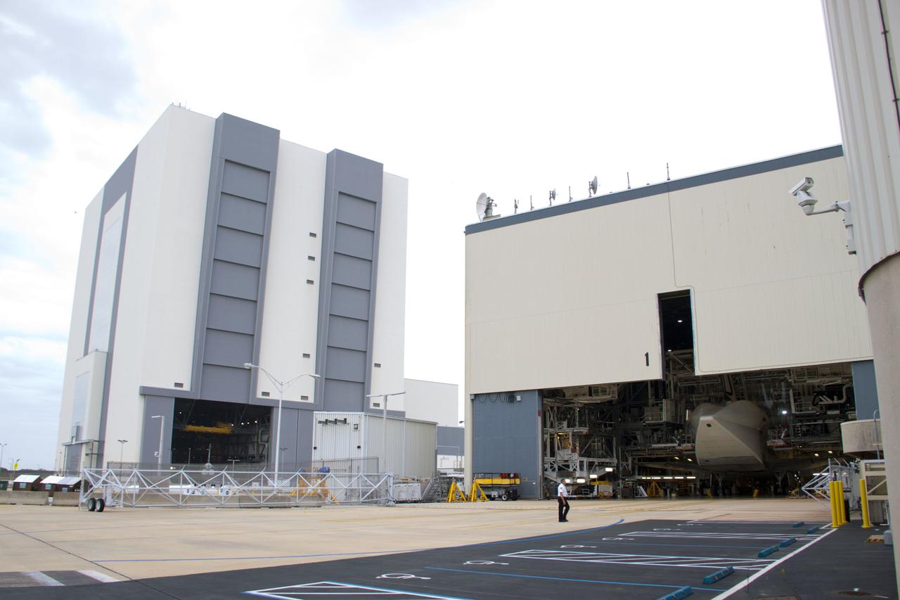
CAPE CANAVERAL, Fla. – A replica shuttle main engine (RSME) rolls out of the Pratt & Whitney Rocketdyne engine shop at NASA’s Kennedy Space Center in Florida toward Orbiter Processing Facility-1 where it will be installed on space shuttle Discovery. In the background is the 525-foot-tall Vehicle Assembly Building. The RSME is one of three that will be installed on Discovery during Space Shuttle Program transition and retirement activities. Discovery is being prepared for display at the Smithsonian’s National Air and Space Museum Steven F. Udvar-Hazy Center in Chantilly, Va. For more information, visit http://www.nasa.gov/shuttle. Photo credit: NASA/Jim Grossmann
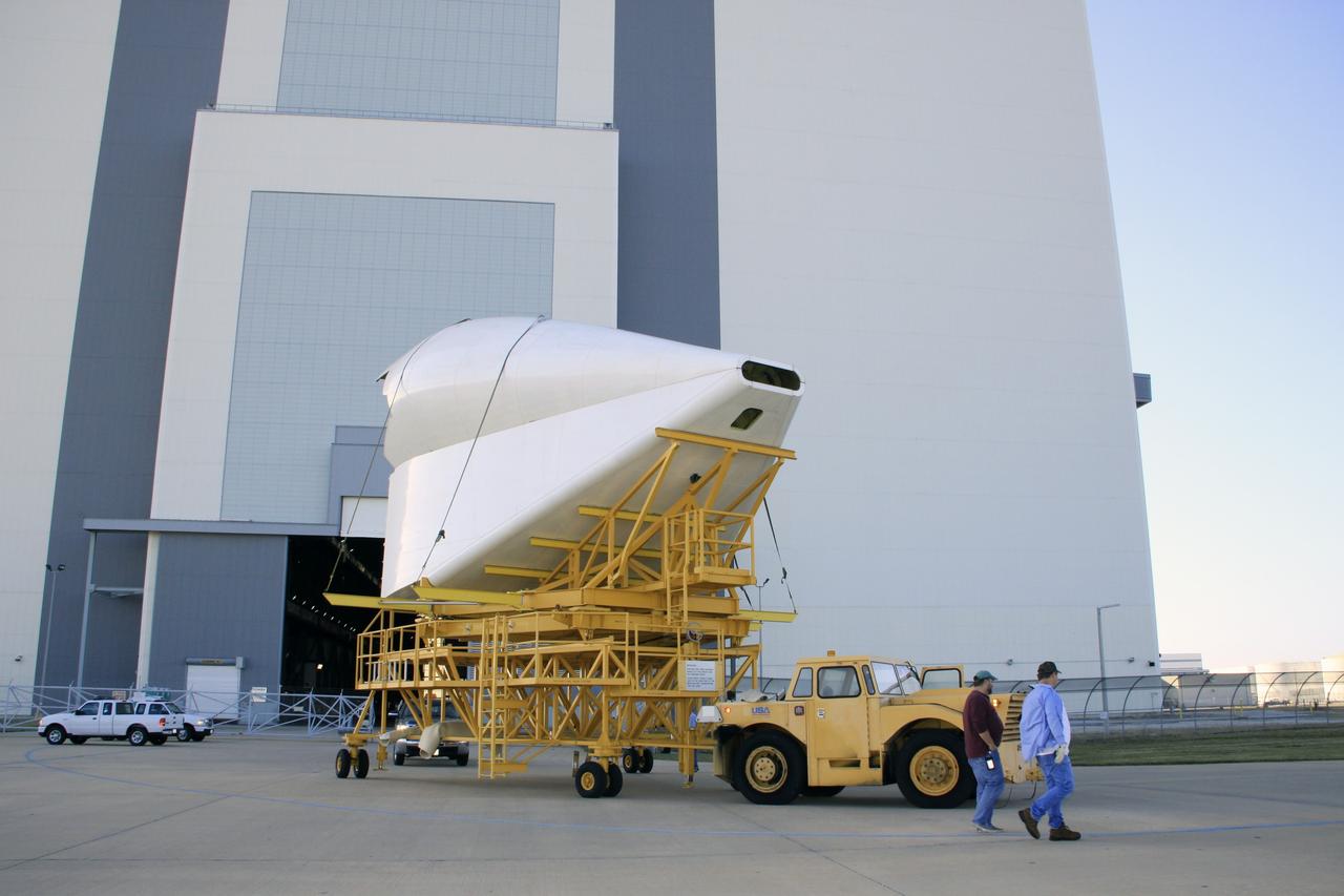
CAPE CANAVERAL, Fla. -- The tail cone for space shuttle Discovery’s three replica shuttle main engines (RSMEs) is being transported from the Vehicle Assembly Building to Orbiter Processing Facility-1 at NASA’s Kennedy Space Center in Florida. The tail cone will be installed around Discovery’s RSMEs for protection. The work is part of the Space Shuttle Program’s transition and retirement processing of shuttle Discovery. Discovery is being prepared for display at the Smithsonian’s National Air and Space Museum, Steven F. Udvar-Hazy Center in Chantilly, Va. For more information, visit http://www.nasa.gov/shuttle. Photo credit: NASA/Jim Grossmann
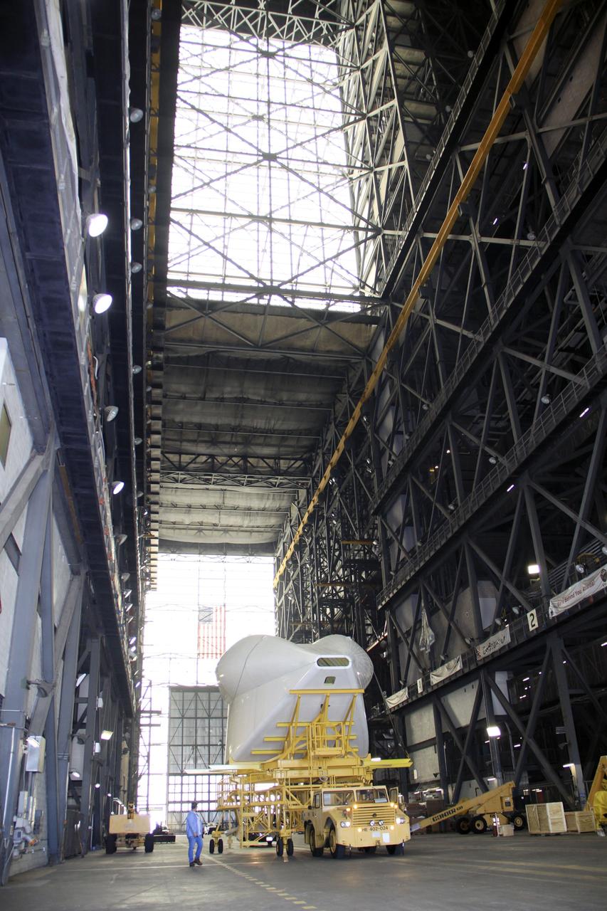
CAPE CANAVERAL, Fla. -- In the transfer aisle of the Vehicle Assembly Building at NASA’s Kennedy Space Center in Florida, the tail cone for space shuttle Discovery’s three replica shuttle main engines (RSMEs) is being transported to Orbiter Processing Facility-1. The tail cone will be installed around Discovery’s RSMEs for protection. The work is part of the Space Shuttle Program’s transition and retirement processing of shuttle Discovery. Discovery is being prepared for display at the Smithsonian’s National Air and Space Museum, Steven F. Udvar-Hazy Center in Chantilly, Va. For more information, visit http://www.nasa.gov/shuttle. Photo credit: NASA/Jim Grossmann
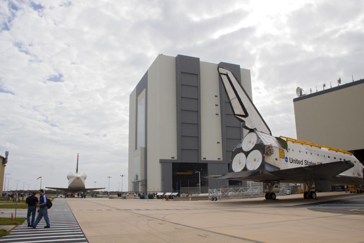
CAPE CANAVERAL, Fla. – At NASA’s Kennedy Space Center in Florida, space shuttle Atlantis foreground is towed in to Orbiter Processing Facility-1 after being towed from the Vehicle Assembly Building VAB. Workers will continue to prepare Atlantis for display at the Kennedy Space Center Visitor Complex. Meanwhile, space shuttle Discovery is on the move from OPF-1 to the Vehicle Assembly Building VAB. The aft view of Discovery reveals the tail cone that covers the three replica shuttle main engines. The work is part of the Space Shuttle Program’s transition and retirement processing of shuttle Discovery, which is being prepared for display at Smithsonian’s National Air and Space Museum, Steven F. Udvar-Hazy Center in Chantilly, Va. Discovery will remain in high bay 4 of the VAB until its scheduled transport atop a NASA Shuttle Carrier Aircraft modified 747 jet to Dulles International Airport in Virginia on April 17. Discovery will then be transported to the Smithsonian on April 19. For more information, visit http://www.nasa.gov/shuttle. Photo credit: NASA/Jim Grossmann
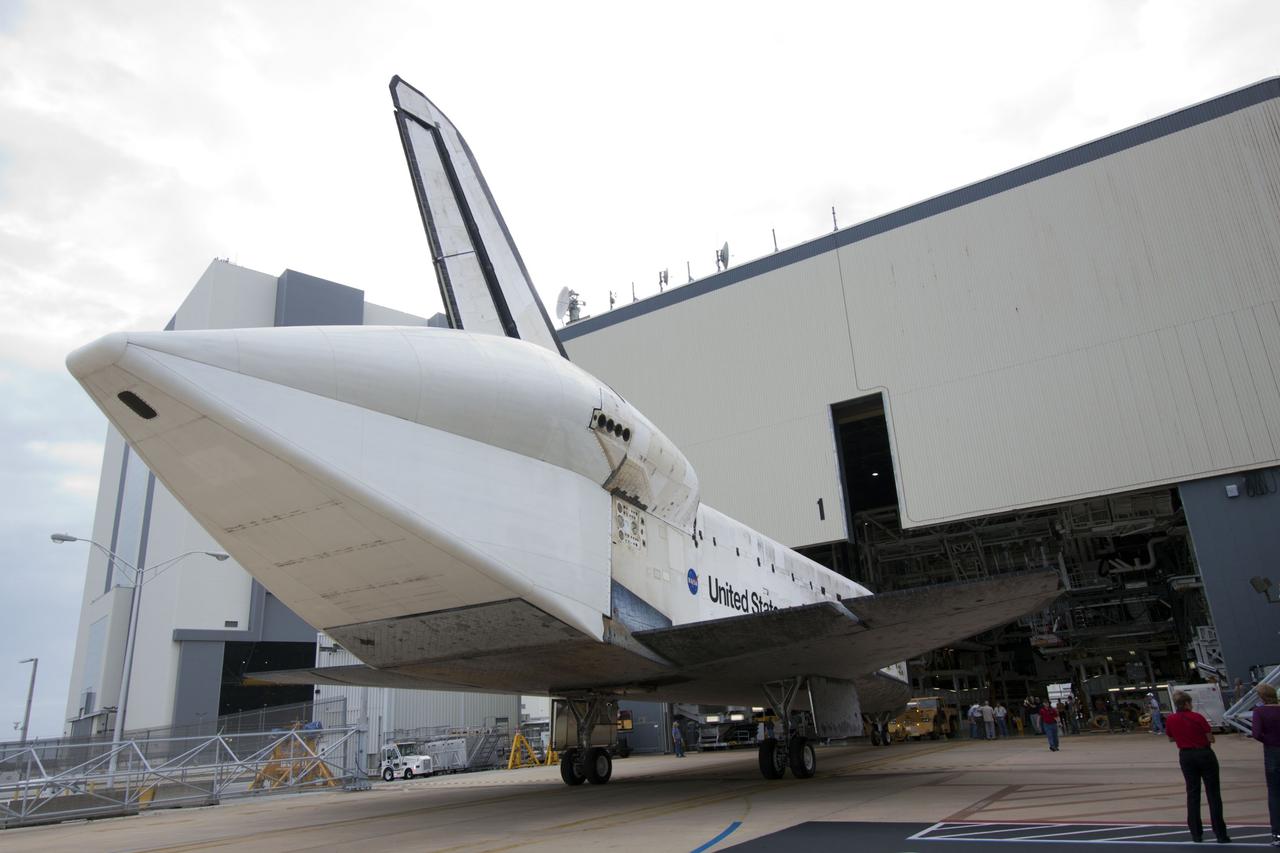
CAPE CANAVERAL, Fla. – At NASA’s Kennedy Space Center in Florida, space shuttle Discovery is backed out of Orbiter Processing Facility-1 for its move to the Vehicle Assembly Building VAB. The aft view of Discovery reveals the tail cone that covers the three replica shuttle main engines. The work is part of the Space Shuttle Program’s transition and retirement processing of shuttle Discovery, which is being prepared for display at Smithsonian’s National Air and Space Museum, Steven F. Udvar-Hazy Center in Chantilly, Va. Discovery will remain in high bay 4 of the VAB until its scheduled transport atop a NASA Shuttle Carrier Aircraft modified 747 jet to Dulles International Airport in Virginia on April 17. Discovery will then be transported to the Smithsonian on April 19. For more information, visit http://www.nasa.gov/shuttle. Photo credit: NASA/Jim Grossmann

CAPE CANAVERAL, Fla. – Workers walk alongside space shuttle Discovery as it is towed to the Vehicle Assembly Building VAB from Orbiter Processing Facility-1 at NASA’s Kennedy Space Center in Florida. The aft view of Discovery reveals the tail cone that covers the three replica shuttle main engines. The work is part of the Space Shuttle Program’s transition and retirement processing of shuttle Discovery, which is being prepared for display at Smithsonian’s National Air and Space Museum, Steven F. Udvar-Hazy Center in Chantilly, Va. Discovery will remain in high bay 4 of the VAB until its scheduled transport atop a NASA Shuttle Carrier Aircraft modified 747 jet to Dulles International Airport in Virginia on April 17. Discovery will then be transported to the Smithsonian on April 19. For more information, visit http://www.nasa.gov/shuttle. Photo credit: NASA/Jim Grossmann
CAPE CANAVERAL, Fla. – At NASA’s Kennedy Space Center in Florida, space shuttle Discovery is backed out of Orbiter Processing Facility-1 for its move to the Vehicle Assembly Building VAB. The aft view of Discovery reveals the tail cone that covers the three replica shuttle main engines. The work is part of the Space Shuttle Program’s transition and retirement processing of shuttle Discovery, which is being prepared for display at Smithsonian’s National Air and Space Museum, Steven F. Udvar-Hazy Center in Chantilly, Va. Discovery will remain in high bay 4 of the VAB until its scheduled transport atop a NASA Shuttle Carrier Aircraft modified 747 jet to Dulles International Airport in Virginia on April 17. Discovery will then be transported to the Smithsonian on April 19. For more information, visit http://www.nasa.gov/shuttle. Photo credit: NASA/Jim Grossmann

CAPE CANAVERAL, Fla. – Inside Orbiter Processing Facility-1 at NASA’s Kennedy Space Center in Florida, space shuttle Discovery is being readied for its move to the Vehicle Assembly Building VAB. The aft view of Discovery reveals the tail cone that covers the three replica shuttle main engines. The work is part of the Space Shuttle Program’s transition and retirement processing of shuttle Discovery, which is being prepared for display at Smithsonian’s National Air and Space Museum, Steven F. Udvar-Hazy Center in Chantilly, Va. Discovery will remain in high bay 4 of the VAB until its scheduled transport atop a NASA Shuttle Carrier Aircraft modified 747 jet to Dulles International Airport in Virginia on April 17. Discovery will then be transported to the Smithsonian on April 19. For more information, visit http://www.nasa.gov/shuttle. Photo credit: NASA/Jim Grossmann
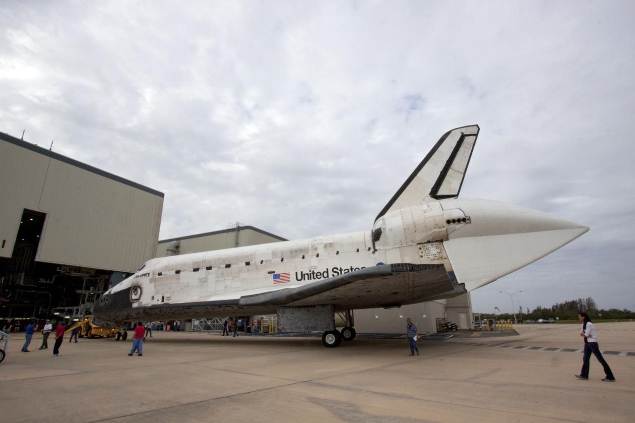
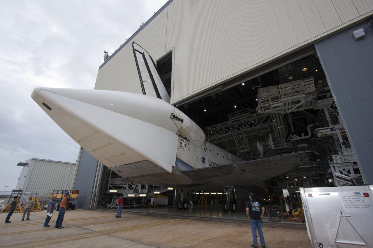
CAPE CANAVERAL, Fla. – At NASA’s Kennedy Space Center in Florida, space shuttle Discovery has been completely backed out of Orbiter Processing Facility-1 in preparation for its move to the Vehicle Assembly Building VAB. The aft view of Discovery reveals the tail cone that covers the three replica shuttle main engines. The work is part of the Space Shuttle Program’s transition and retirement processing of shuttle Discovery, which is being prepared for display at Smithsonian’s National Air and Space Museum, Steven F. Udvar-Hazy Center in Chantilly, Va. Discovery will remain in high bay 4 of the VAB until its scheduled transport atop a NASA Shuttle Carrier Aircraft modified 747 jet to Dulles International Airport in Virginia on April 17. Discovery will then be transported to the Smithsonian on April 19. For more information, visit http://www.nasa.gov/shuttle. Photo credit: NASA/Jim Grossmann
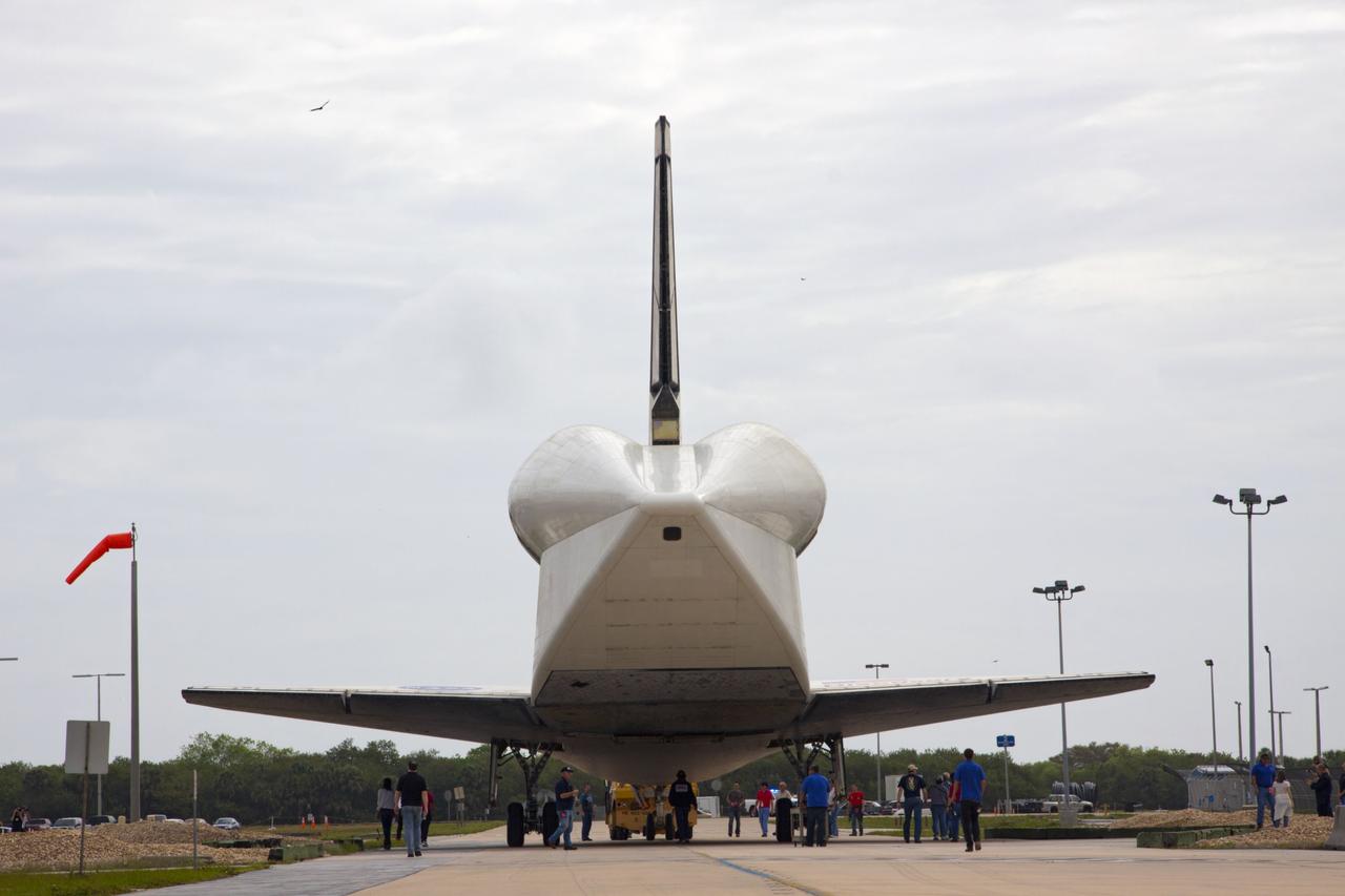
CAPE CANAVERAL, Fla. – At NASA’s Kennedy Space Center in Florida, space shuttle Discovery is towed to the Vehicle Assembly Building VAB after being towed out of Orbiter Processing Facility-1. The aft view of Discovery reveals the tail cone that covers the three replica shuttle main engines. The work is part of the Space Shuttle Program’s transition and retirement processing of shuttle Discovery, which is being prepared for display at Smithsonian’s National Air and Space Museum, Steven F. Udvar-Hazy Center in Chantilly, Va. Discovery will remain in high bay 4 of the VAB until its scheduled transport atop a NASA Shuttle Carrier Aircraft modified 747 jet to Dulles International Airport in Virginia on April 17. Discovery will then be transported to the Smithsonian on April 19. For more information, visit http://www.nasa.gov/shuttle. Photo credit: NASA/Jim Grossmann
CAPE CANAVERAL, Fla. – Inside Orbiter Processing Facility-1 at NASA’s Kennedy Space Center in Florida, space shuttle Discovery is being readied for its move to the Vehicle Assembly Building VAB. The aft view of Discovery reveals the tail cone that covers the three replica shuttle main engines. The work is part of the Space Shuttle Program’s transition and retirement processing of shuttle Discovery, which is being prepared for display at Smithsonian’s National Air and Space Museum, Steven F. Udvar-Hazy Center in Chantilly, Va. Discovery will remain in high bay 4 of the VAB until its scheduled transport atop a NASA Shuttle Carrier Aircraft modified 747 jet to Dulles International Airport in Virginia on April 17. Discovery will then be transported to the Smithsonian on April 19. For more information, visit http://www.nasa.gov/shuttle. Photo credit: NASA/Jim Grossmann
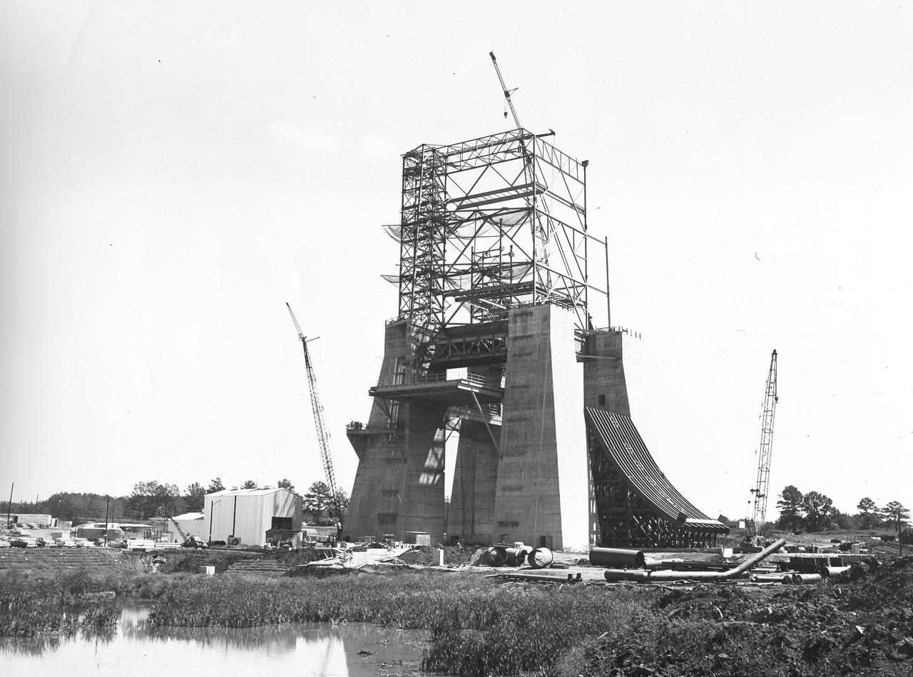
At its founding, the Marshall Space Flight Center (MSFC) inherited the Army’s Jupiter and Redstone test stands, but much larger facilities were needed for the giant stages of the Saturn V. From 1960 to 1964, the existing stands were remodeled and a sizable new test area was developed. The new comprehensive test complex for propulsion and structural dynamics was unique within the nation and the free world, and they remain so today because they were constructed with foresight to meet the future as well as on going needs. Construction of the S-IC Static test stand complex began in 1961 in the west test area of MSFC, and was completed in 1964. The S-IC static test stand was designed to develop and test the 138-ft long and 33-ft diameter Saturn V S-IC first stage, or booster stage, weighing in at 280,000 pounds. Required to hold down the brute force of a 7,500,000-pound thrust produced by 5 F-1 engines, the S-IC static test stand was designed and constructed with the strength of hundreds of tons of steel and 12,000,000 pounds of cement, planted down to bedrock 40 feet below ground level. The foundation walls, constructed with concrete and steel, are 4 feet thick. The base structure consists of four towers with 40-foot-thick walls extending upward 144 feet above ground level. The structure was topped by a crane with a 135-foot boom. With the boom in the upright position, the stand was given an overall height of 405 feet, placing it among the highest structures in Alabama at the time. In addition to the stand itself, related facilities were constructed during this time. Built to the northeast of the stand was a newly constructed Pump House. Its function was to provide water to the stand to prevent melting damage during testing. The water was sprayed through small holes in the stand’s 1900 ton flame deflector at the rate of 320,000 gallons per minute. In this photo of the S-IC test stand, taken September 25, 1963, the flame deflector can be seen rotated to the outside on the right. The deflector was assembled on tracks for mobility.
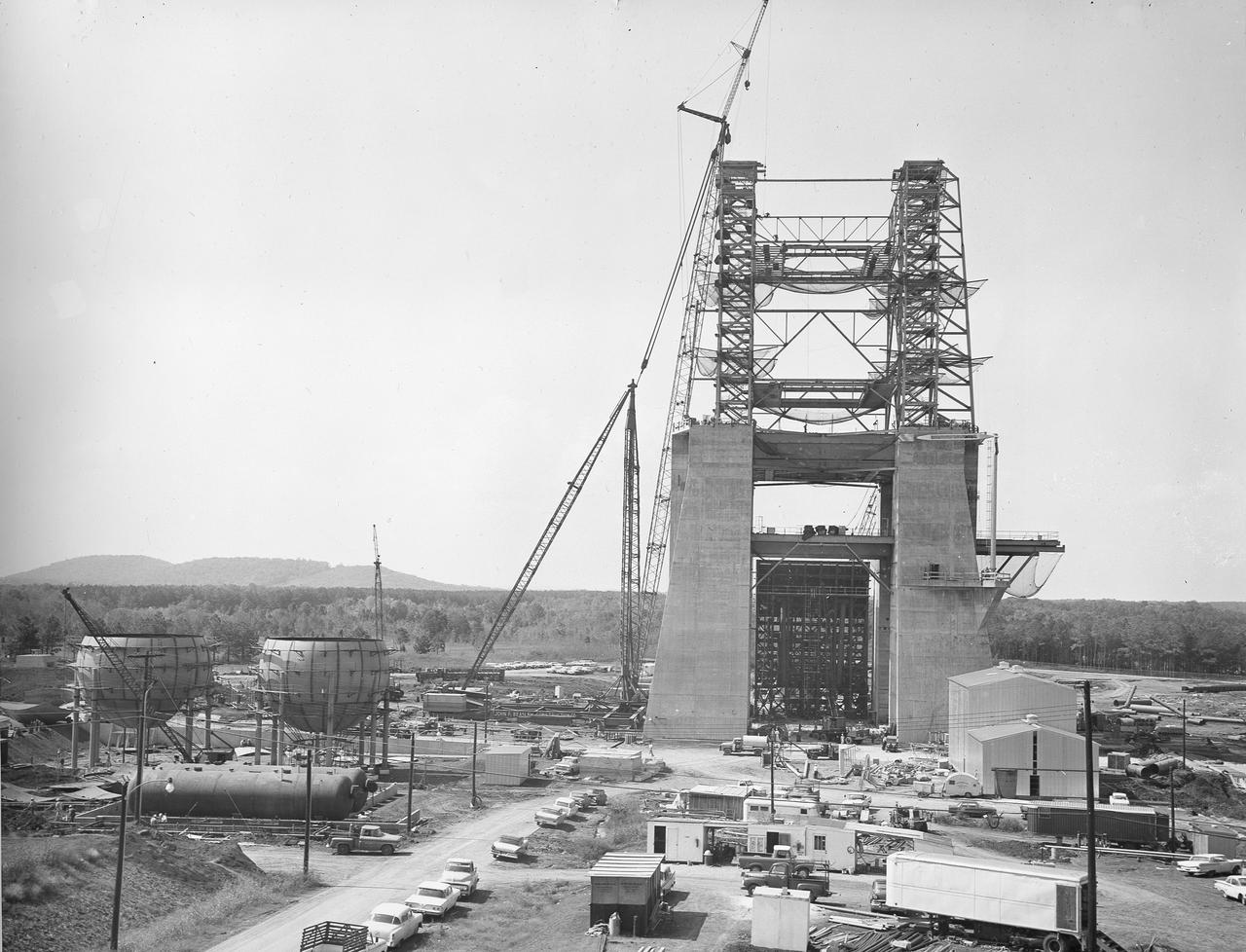
At its founding, the Marshall Space Flight Center (MSFC) inherited the Army’s Jupiter and Redstone test stands, but much larger facilities were needed for the giant stages of the Saturn V. From 1960 to 1964, the existing stands were remodeled and a sizable new test area was developed. The new comprehensive test complex for propulsion and structural dynamics was unique within the nation and the free world, and they remain so today because they were constructed with foresight to meet the future as well as on going needs. Construction of the S-IC Static test stand complex began in 1961 in the west test area of MSFC, and was completed in 1964. The S-IC static test stand was designed to develop and test the 138-ft long and 33-ft diameter Saturn V S-IC first stage, or booster stage, weighing in at 280,000 pounds. Required to hold down the brute force of a 7,500,000-pound thrust produced by 5 F-1 engines, the S-IC static test stand was designed and constructed with the strength of hundreds of tons of steel and 12,000,000 pounds of cement, planted down to bedrock 40 feet below ground level. The foundation walls, constructed with concrete and steel, are 4 feet thick. The base structure consists of four towers with 40-foot-thick walls extending upward 144 feet above ground level. The structure was topped by a crane with a 135-foot boom. With the boom in the upright position, the stand was given an overall height of 405 feet, placing it among the highest structures in Alabama at the time. In addition to the stand itself, related facilities were constructed during this time. Built to the northeast of the stand was a newly constructed Pump House. Its function was to provide water to the stand to prevent melting damage during testing. The water was sprayed through small holes in the stand’s 1900 ton flame deflector at the rate of 320,000 gallons per minute. In this photo of the S-IC test stand, taken October 2, 1963, the flame deflector can be seen in the bottom center portion of the stand. The deflector was assembled on tracks for mobility. To the left of the stand are two spherical hydrogen storage tanks.
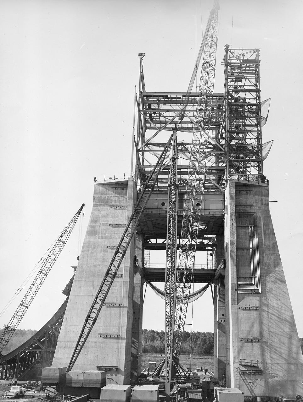
At its founding, the Marshall Space Flight Center (MSFC) inherited the Army’s Jupiter and Redstone test stands, but much larger facilities were needed for the giant stages of the Saturn V. From 1960 to 1964, the existing stands were remodeled and a sizable new test area was developed. The new comprehensive test complex for propulsion and structural dynamics was unique within the nation and the free world, and they remain so today because they were constructed with foresight to meet the future as well as on going needs. Construction of the S-IC Static test stand complex began in 1961 in the west test area of MSFC, and was completed in 1964. The S-IC static test stand was designed to develop and test the 138-ft long and 33-ft diameter Saturn V S-IC first stage, or booster stage, weighing in at 280,000 pounds. Required to hold down the brute force of a 7,500,000-pound thrust produced by 5 F-1 engines, the S-IC static test stand was designed and constructed with the strength of hundreds of tons of steel and 12,000,000 pounds of cement, planted down to bedrock 40 feet below ground level. The foundation walls, constructed with concrete and steel, are 4 feet thick. The base structure consists of four towers with 40-foot-thick walls extending upward 144 feet above ground level. The structure was topped by a crane with a 135-foot boom. With the boom in the upright position, the stand was given an overall height of 405 feet, placing it among the highest structures in Alabama at the time. In addition to the stand itself, related facilities were constructed during this time. Built to the northeast of the stand was a newly constructed Pump House. Its function was to provide water to the stand to prevent melting damage during testing. The water was sprayed through small holes in the stand’s 1900 ton flame deflector at the rate of 320,000 gallons per minute. In this photo of the S-IC test stand, taken September 25, 1963, the flame deflector can be seen rotated to the outside on the left. The deflector was assembled on tracks for mobility.