
F-15A #281 In Flight
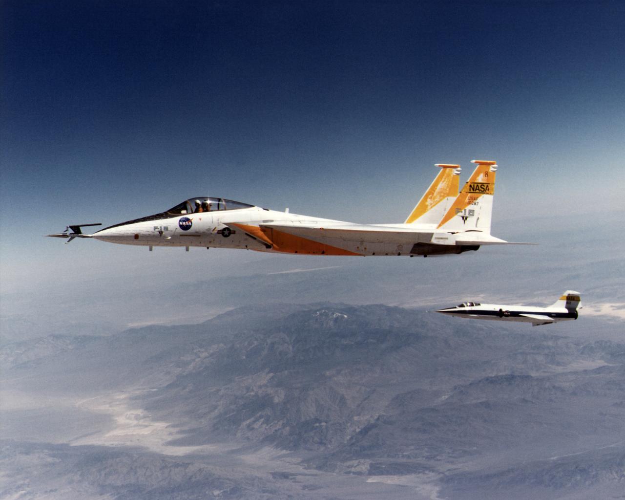
An in-flight photo of the NASA F-15A used to carry a 10 degree cone to collect aerodynamic data to calibrate the data from wind tunnels. The flight was made on May 17, 1978. Acting as chase for the flight was a NASA F-104 aircraft.
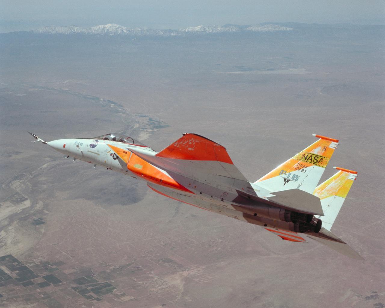
An in-flight photo of the NASA F-15A with a 10 degree cone to collect aerodynamic information to calibrate data from wind tunnels.

F-15A #281 In Flight over Mojave.
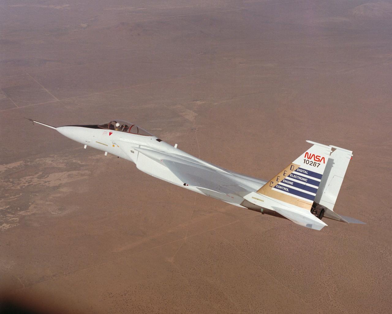
Digital Electronic Engine Control F-15A #287 in flight.
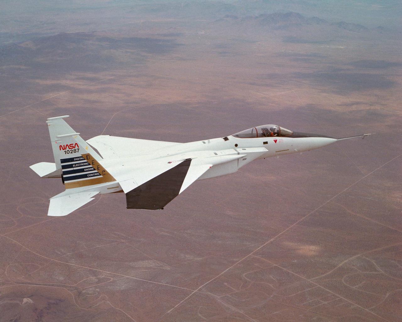
Digital Electronic Engine Control F-15A #287 in flight over California City. Note wing deflection measurement system on right wing.
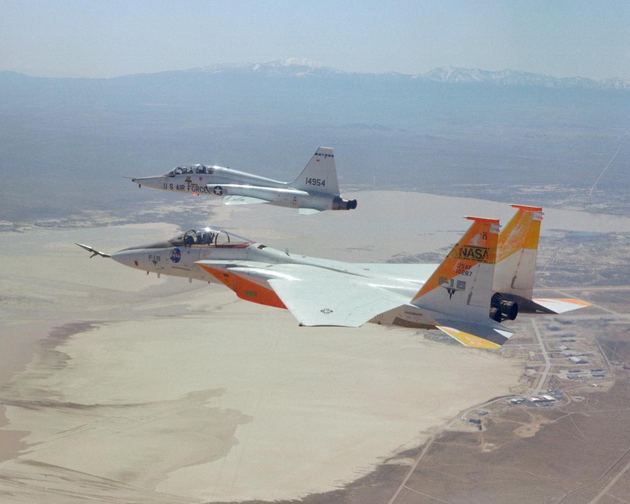
An in-flight photo of the NASA F-15A used to carry a 10 degree cone to collect aerodynamic data to calibrate the data from wind tunnels. Acting as chase for the flight was a NASA T-38 aircraft.
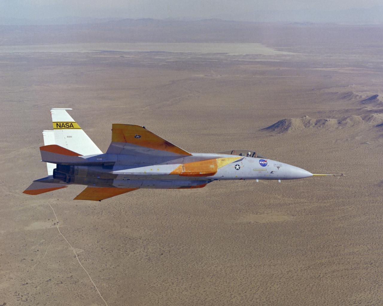
The number two F-15A (Serial #71-0281) was obtained by NASA from the U.S. Air Force in 1976 and was used for more than 25 advanced research projects involving aerodynamics, performance, propulsion control, control integration, instrumentation development, human factors, and flight test techniques. Included in these projects was its role as a testbed to evaluate aerodynamic pressures on Space Shuttle thermal protection tiles at specific altitudes and speeds.
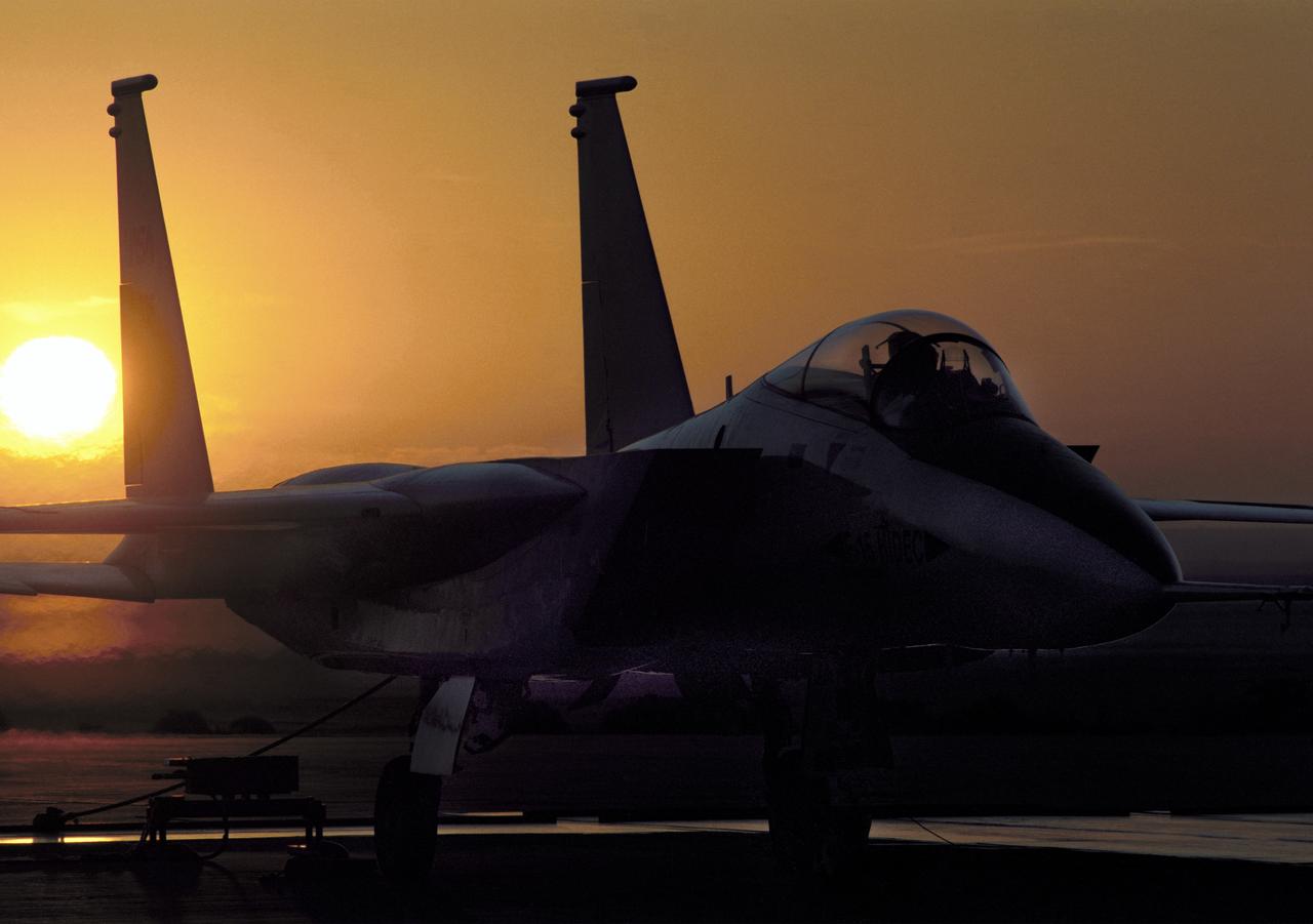
NASA's highly modified F-15A (Serial #71-0287) used for digital electronic flight and engine control systems research, at sunrise on the ramp at the Dryden Flight Research Facility, Edwards, California. The F-15 was called the HIDEC (Highly Integrated Digital Electronic Control) flight facility. Research programs flown on the testbed vehicle have demonstrated improved rates of climb, fuel savings, and engine thrust by optimizing systems performance. The aircraft also tested and evaluated a computerized self-repairing flight control system for the Air Force that detects damaged or failed flight control surfaces. The system then reconfigures undamaged control surfaces so the mission can continue or the aircraft is landed safely.
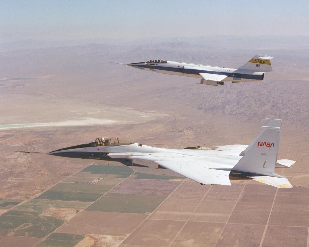
F-15 #281 and F-104 #826 fly in formation during Space Shuttle tile testing. Note the tiles mounted on the right wing of the F-15 and the centerline test fixture of the F-104.

P-34712 Range: 1.1 million kilometers (683,000 miles) This wide-angle Voyager 2 image, taken through the camera's clear filter, is the first to show Neptune's rings in detail. The two main rings, about 53,000 km (33,000 miles) and 63,000 km (39,000 miles) from Neptune, are 5 to 10 times brighter than in earlier images. The difference is due to lighting and viewing geometry. In approach images, the rings were seen in light scattered backward toward the spacecraft at a 15° phase angle. However, this image was taken at a 135° phase angle as Voyager left the planet. That geometry is ideal for detecting microscopic particles that forward scatter light preferentially. The fact that Neptune's rings are so much brighter at that angle means the particle-size distribution is quite different from most of Uranus' and Saturn's rings, which contain fewer dust-size grains. However, a few componenets of the Saturian and Uranian ring systems exhibit forward-scattering behavior: The F ring and the Encke Gap ringlet at Saturn and 1986U1R at Uranus. They are also narrow, clumpy ringlets with kinks, and are associated with nearby moonlets too small to detect directly. In this image, the main clumpy arc, composed of three features each about 6 to 8 degrees long, is clearly seen. Exposure time for this image was 111 seconds.