
STS075-360-021 (22 Feb.- 9 March 1996) --- The loose tether forms a faint diagonal line in this scene recorded on a later fly-by. On Feb. 25, 1996, the crew deployed the Tethered Satellite System (TSS), which later broke free. The seven member crew was launched aboard the space shuttle Columbia on Feb. 22, 1996, and landed on March 9, 1996. Crew members were Andrew M. Allen, mission commander; Scott J. Horowitz, pilot; Franklin R. Chang-Diaz, payload commander; and Maurizio Cheli, European Space Agency (ESA); Jeffrey A. Hoffman and Claude Nicollier, ESA, all mission specialists; along with payload specialist Umberto Guidoni of the Italian Space Agency (ASI).
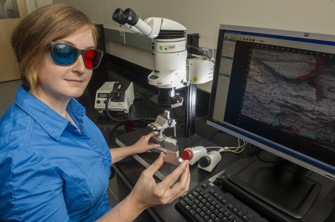
ELLEN RABENBERG, EM31, FAILURE ANALYSIS AND METALLURGY BRANCH, DIAGNOSTICS TEAM MEMBER WITH 3D MICROSCOPE
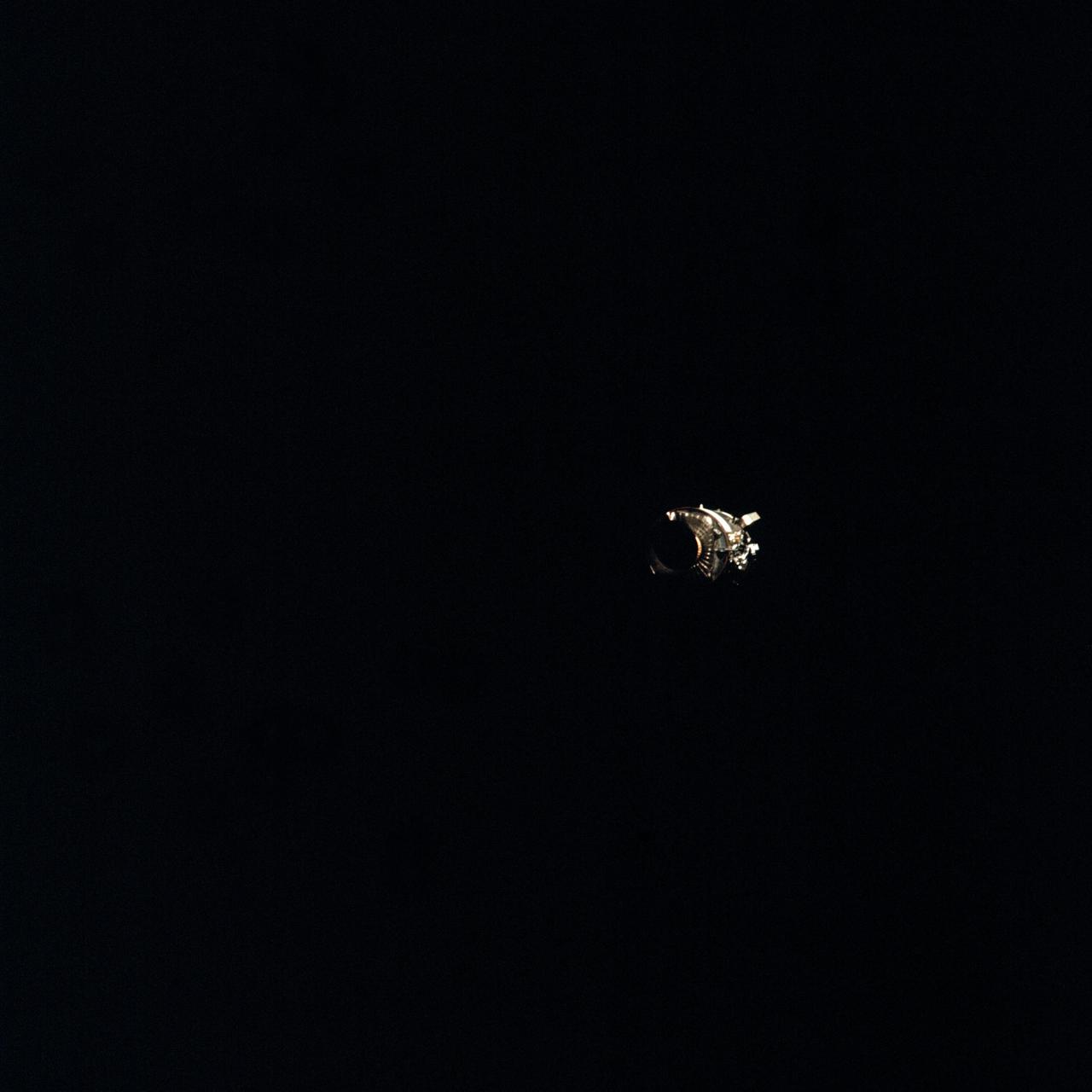
AS13-58-8458 (17 April 1970) --- This view of the severely damaged Apollo 13 Service Module (SM) was photographed from the Lunar Module/Command Module (LM/CM) following SM jettisoning. An entire SM panel was blown away by the apparent explosion of oxygen tank number two. Two of the three fuel cells are visible at the forward portion of the opening. The hydrogen tanks are located in Sector 4 of the Apollo 13 SM. The apparent rupture of the oxygen tank caused the Apollo 13 crew members to use the LM as a "lifeboat." The LM was jettisoned just prior to Earth re-entry by the CM.
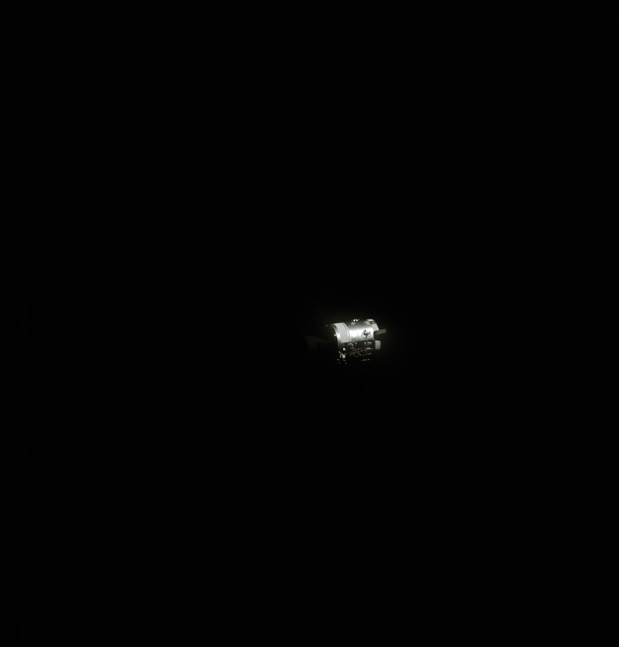
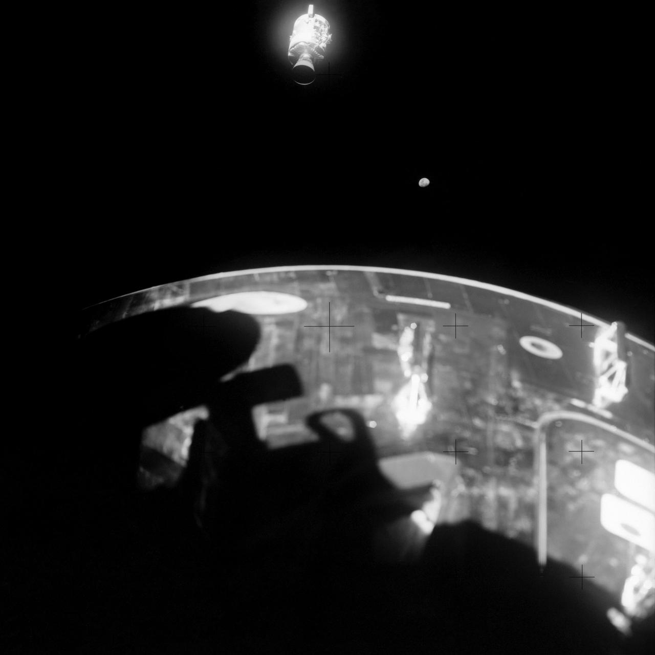
AS13-58-8464 (17 April 1970) --- This view of the severely damaged Apollo 13 Service Module (SM) was photographed from the Lunar Module/Command Module (LM/CM) following SM jettisoning. Nearest the camera is the Service Propulsion System (SPS) engine and nozzle. An entire SM panel was blown away by the apparent explosion of oxygen tank number two located in Sector 4 of the SM. The apparent rupture of the oxygen tank caused the Apollo 13 crew men to use the Lunar Module (LM) as a "lifeboat".
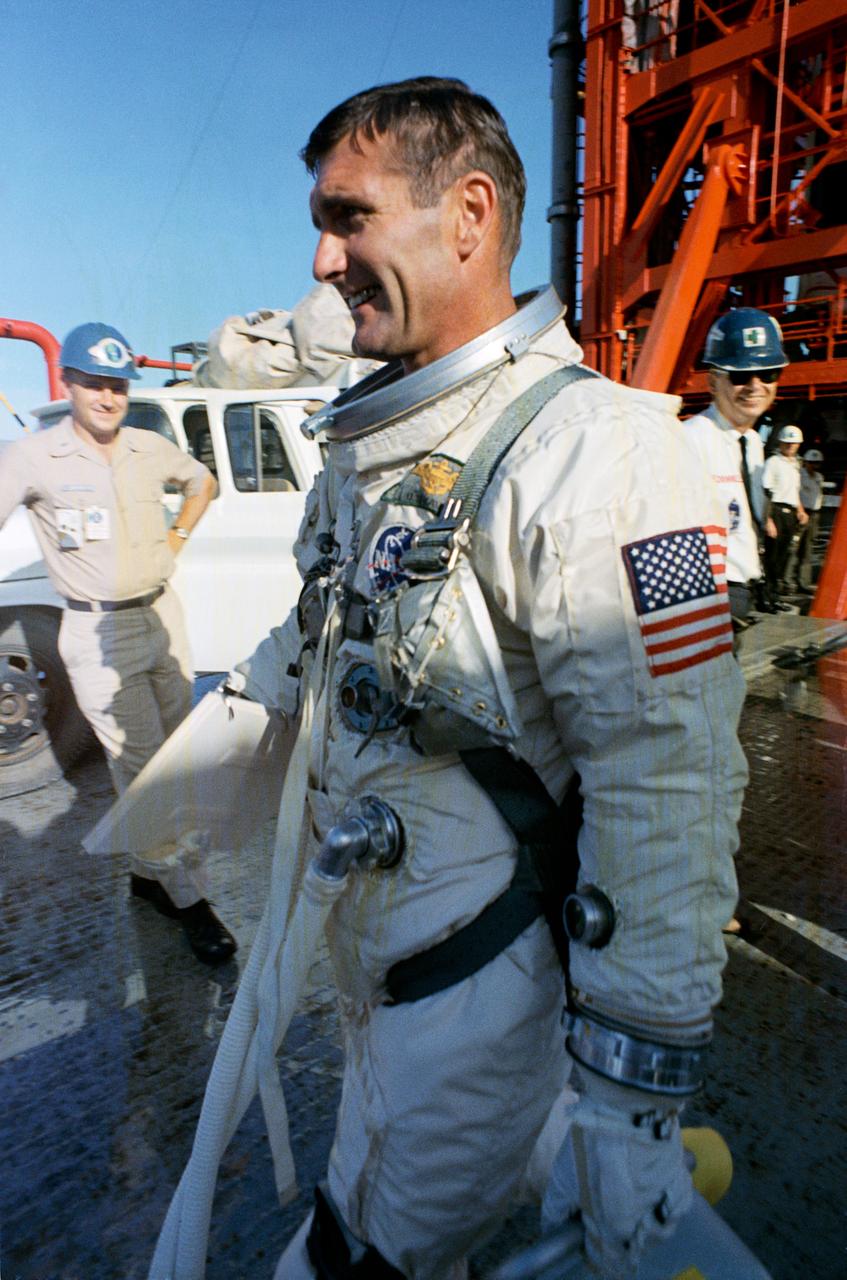
S66-50775 (10 Sept. 1966) --- Astronaut Richard F. Gordon Jr., pilot, walks away from Pad 19 following postponement of the Gemini-11 spaceflight. The mission was rescheduled for Sept. 12, 1966. Photo credit: NASA

AS13-59-8562 (17 April 1970) --- This view of the Apollo 13 Lunar Module (LM) was photographed from the Command Module (CM) just after the LM had been jettisoned. The jettisoning occurred a few minutes before 11 a.m. (CST), April 17, 1970, just over an hour prior to splashdown of the CM in the south Pacific Ocean. The apparent explosion of oxygen tank number two in the Apollo 13 Service Module (SM) caused the Apollo 13 crew members to rely on the LM as a "lifeboat".
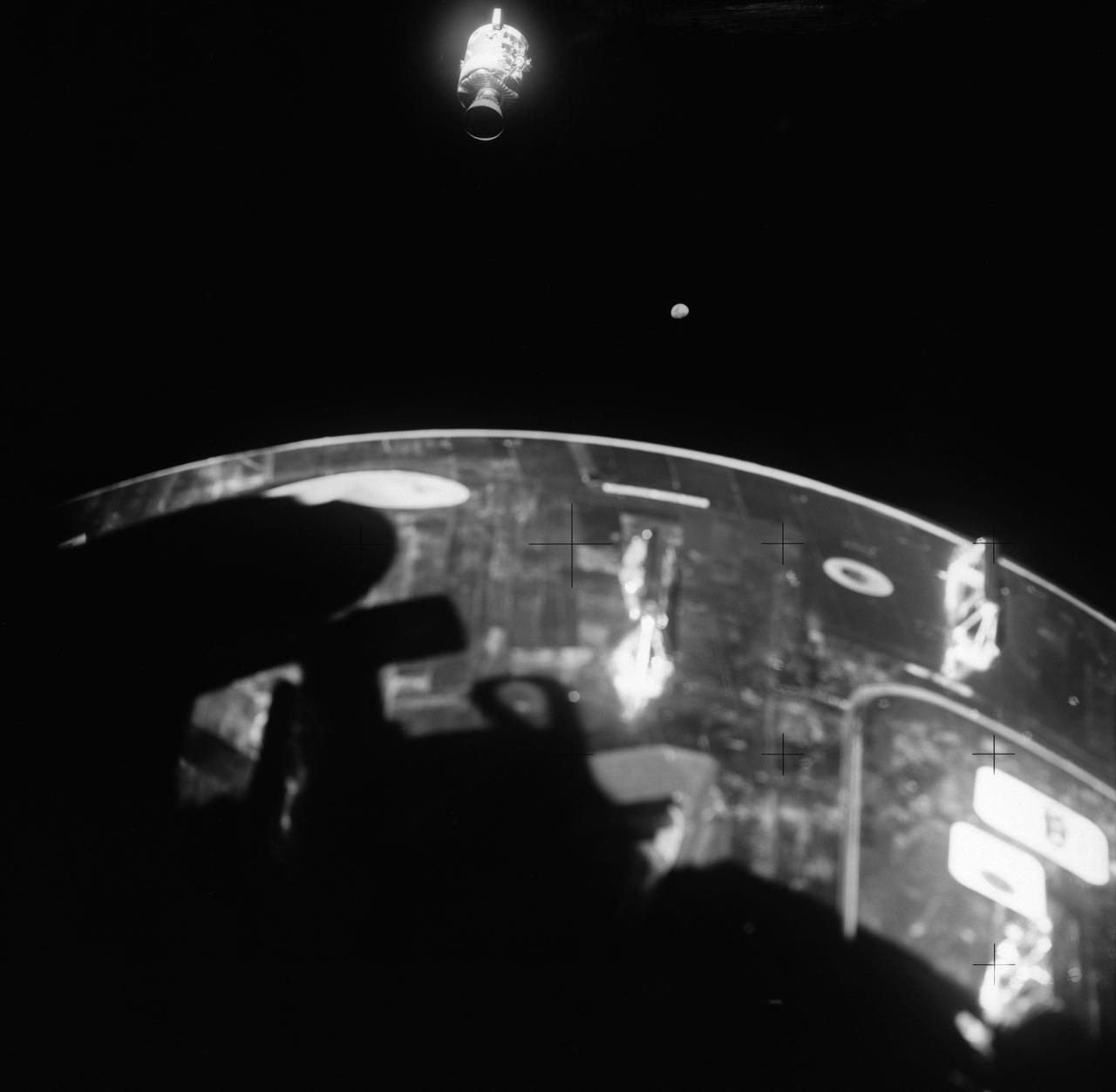
This view of the damaged Apollo 13 Service Module (SM) was photographed from the Lunar Module/Command Module following SM jettisoning. As seen here, an entire panel on the SM was blown away by the apparent explosion of oxygen tank number two located in Sector 4 of the SM. Two of the three fuel cells are visible just forward (above) the heavily damaged area. Three fuel cells, two oxygen tanks, and two hydrogen tanks are locate in Sector 4. The damaged area is located above the S-band high gain antenna. Nearest the camera is the Service Propulsion System (SPS) engine and nozzle. The damage to the SM caused the Apollo 13 crewmen to use the Lunar Module (LM) as a "lifeboat". The LM was jettisoned just prior to Earth reentry by the Command Module.
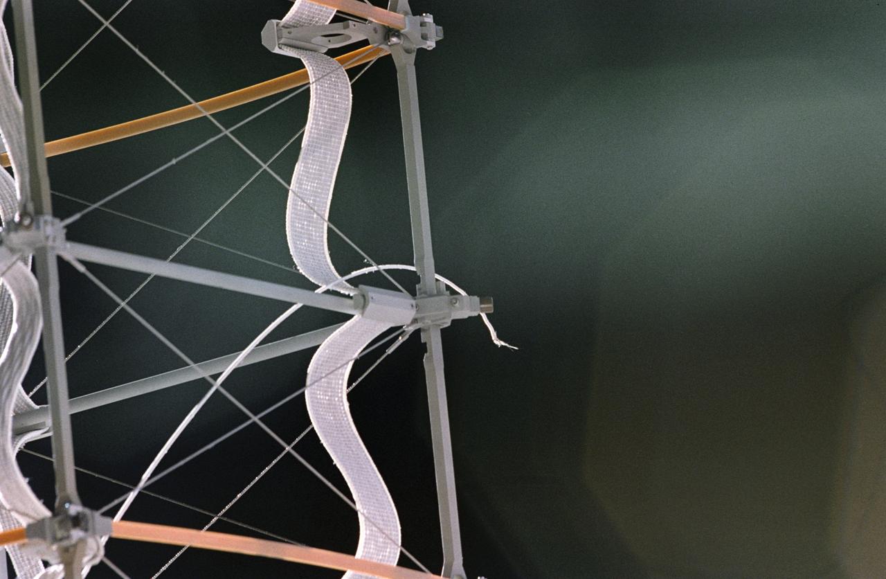
STS075-325-014 (25 Feb. 1996) --- The frayed end of the tether portion of the Tethered Satellite System (TSS) is seen at the end of the supportive boom. On February 25, 1996, the crew deployed the TSS, which later broke free. The seven member crew was launched aboard the Space Shuttle Columbia on February 22, 1996, and landed on March 9, 1996. Crewmembers were Andrew M. Allen, mission commander; Scott J. Horowitz, pilot; Franklin R. Chang-Diaz, payload commander; and Maurizio Cheli, European Space Agency (ESA); Jeffrey A. Hoffman and Claude Nicollier (ESA), all mission specialists; along with payload specialist Umberto Guidoni of the Italian Space Agency (ASI).
AS13-59-8501 (17 April 1970) --- This view of the severely damaged Apollo 13 Service Module (SM) was photographed from the Lunar Module/Command Module (LM/CM) following SM jettisoning. As seen here, an entire panel on the SM was blown away by the apparent explosion of oxygen tank number two located in Sector 4 of the SM. Two of the three fuel cells are visible just forward (above) the heavily damaged area. Three fuel cells, two oxygen tanks, and two hydrogen tanks are located in Sector 4. The damaged area is located above the S-Band high gain antenna. Nearest the camera is the Service Propulsion System (SPS) engine and nozzle. The damage to the SM caused the Apollo 13 crew men to use the LM as a "lifeboat." The LM was jettisoned just prior to Earth re-entry by the CM.
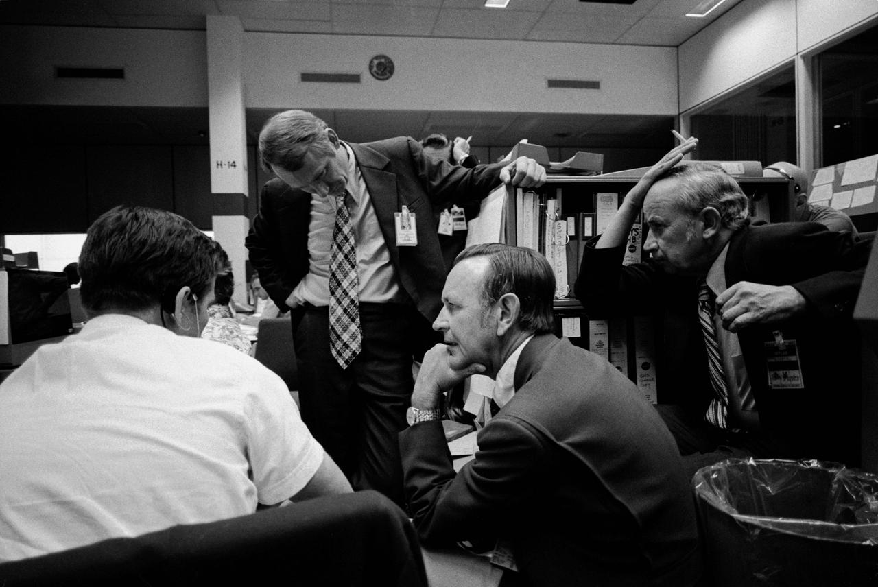
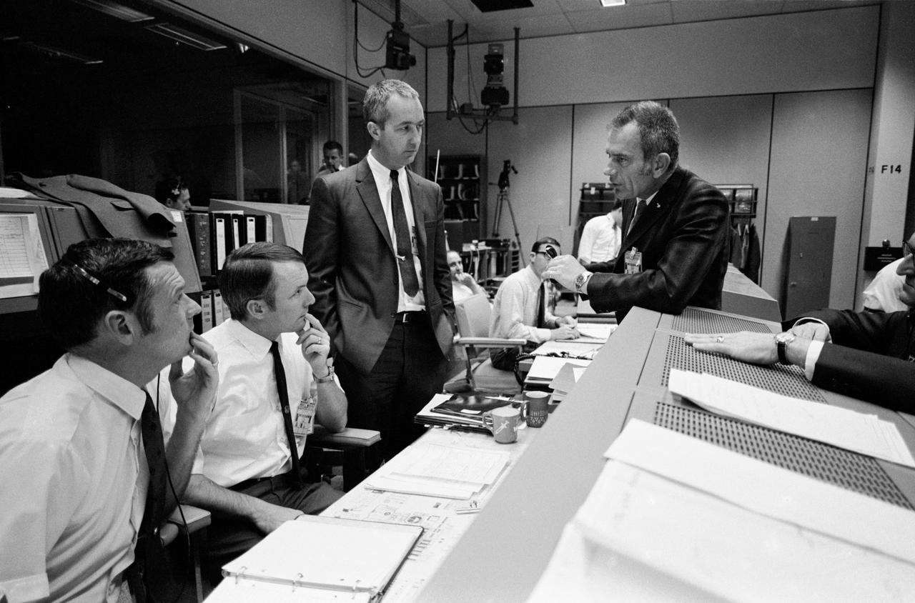
S73-31875 (2 Aug. 1973) --- After learning of a problem in the Command/Service Module which was used to transport the Skylab 3 crew to the orbiting Skylab space station cluster, NASA officials held various meetings to discuss the problem. Here, four men monitor the current status of the problem in the Mission Operations Control Room (MOCR) of the Mission Control Center (MCC) at the Johnson Space Center (JSC). From the left are Gary E. Coen, Guidance and Navigation System flight controller; Howard W. Tindall Jr., Director of Flight Operations at JSC; Dr. Christopher C. Kraft Jr., JSC Director; and Sigurd A. Sjoberg, JSC Deputy Director. Photo credit: NASA

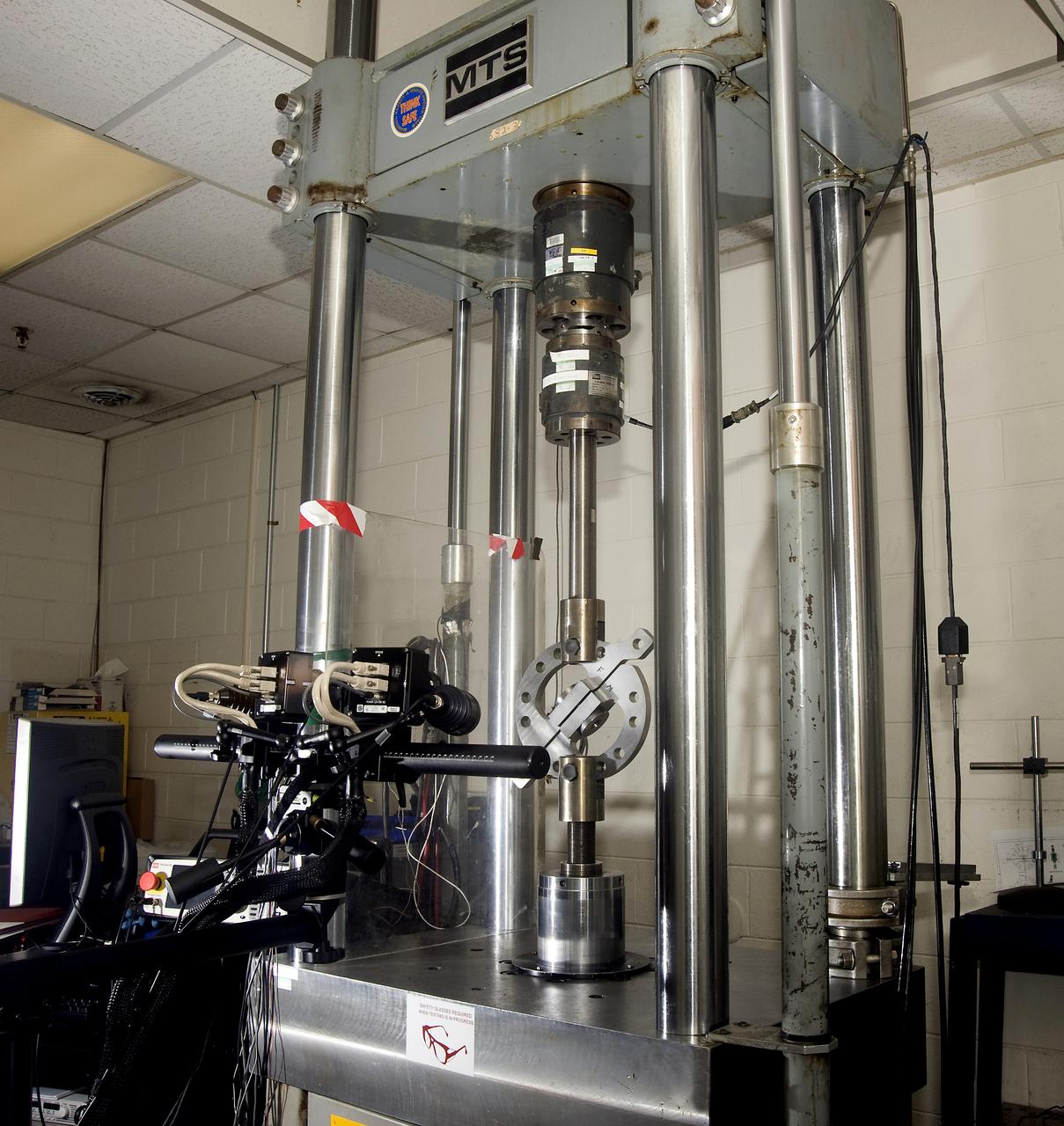
DEVELOPMENT TESTING BEING CONDUCTED AT THE REQUEST OF THE MSFC DYNAMICS, LOADS, AND STRENGTH BRANCH (EV31) TO STUDY THE FAILURE BEHAVIOR OF FASTENERS SUBJECTED TO COMBINED SHEAR AND TENSION LOADING. THE DATA FROM THIS TESTING WILL BE USED TO DEVELOP APPROPRIATE STRUCTURAL ANALYSIS METHODS AS PART OF A FASTENER STANDARDS EFFORT SPONSORED BY THE NASA ENGINEERING SAFETY CENTER (NESC). THE TEST FIXTURE WAS DESIGNED AND FABRICATED THROUGH THE MSFC MECHANICAL FABRICATION BRANCH (ES23). THE TESTING ORGANIZATION IS THE MSFC MATERIALS TEST BRANCH (EM10).
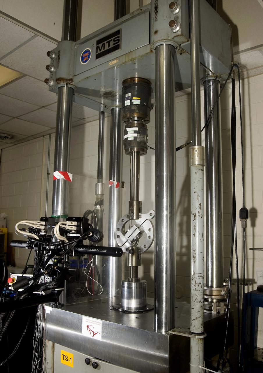
DEVELOPMENT TESTING BEING CONDUCTED AT THE REQUEST OF THE MSFC DYNAMICS, LOADS, AND STRENGTH BRANCH (EV31) TO STUDY THE FAILURE BEHAVIOR OF FASTENERS SUBJECTED TO COMBINED SHEAR AND TENSION LOADING. THE DATA FROM THIS TESTING WILL BE USED TO DEVELOP APPROPRIATE STRUCTURAL ANALYSIS METHODS AS PART OF A FASTENER STANDARDS EFFORT SPONSORED BY THE NASA ENGINEERING SAFETY CENTER (NESC). THE TEST FIXTURE WAS DESIGNED AND FABRICATED THROUGH THE MSFC MECHANICAL FABRICATION BRANCH (ES23). THE TESTING ORGANIZATION IS THE MSFC MATERIALS TEST BRANCH (EM10).
DEVELOPMENT TESTING BEING CONDUCTED AT THE REQUEST OF THE MSFC DYNAMICS, LOADS, AND STRENGTH BRANCH (EV31) TO STUDY THE FAILURE BEHAVIOR OF FASTENERS SUBJECTED TO COMBINED SHEAR AND TENSION LOADING. THE DATA FROM THIS TESTING WILL BE USED TO DEVELOP APPROPRIATE STRUCTURAL ANALYSIS METHODS AS PART OF A FASTENER STANDARDS EFFORT SPONSORED BY THE NASA ENGINEERING SAFETY CENTER (NESC). THE TEST FIXTURE WAS DESIGNED AND FABRICATED THROUGH THE MSFC MECHANICAL FABRICATION BRANCH (ES23). THE TESTING ORGANIZATION IS THE MSFC MATERIALS TEST BRANCH (EM10).

DEVELOPMENT TESTING BEING CONDUCTED AT THE REQUEST OF THE MSFC DYNAMICS, LOADS, AND STRENGTH BRANCH (EV31) TO STUDY THE FAILURE BEHAVIOR OF FASTENERS SUBJECTED TO COMBINED SHEAR AND TENSION LOADING. THE DATA FROM THIS TESTING WILL BE USED TO DEVELOP APPROPRIATE STRUCTURAL ANALYSIS METHODS AS PART OF A FASTENER STANDARDS EFFORT SPONSORED BY THE NASA ENGINEERING SAFETY CENTER (NESC). THE TEST FIXTURE WAS DESIGNED AND FABRICATED THROUGH THE MSFC MECHANICAL FABRICATION BRANCH (ES23). THE TESTING ORGANIZATION IS THE MSFC MATERIALS TEST BRANCH (EM10).
S70-35369 (16 April 1970) --- Discussion in the Mission Operations Control Room (MOCR) dealing with the Apollo 13 crewmen during their final day in space. From left to right are Glynn S. Lunney, Shift 4 flight director; Gerald D. Griffin, Shift 2 flight director; astronaut James A. McDivitt, manager, Apollo Spacecraft Program, MSC; Dr. Donald K. Slayton, director of Flight Crew Operations, MSC; and Dr. Willard R. Hawkins, M.D., Shift 1 flight surgeon.

S70-35368 (16 April 1970) --- Overall view showing some of the feverish activity in the Mission Operations Control Room (MOCR) of the Mission Control Center (MCC) during the final 24 hours of the problem-plagued Apollo 13 mission. Here, flight controllers and several NASA/MSC officials confer at the flight director's console. When this picture was made, the Apollo 13 lunar landing had already been canceled, and the Apollo 13 crewmembers were in trans-Earth trajectory attempting to bring their crippled spacecraft back home.
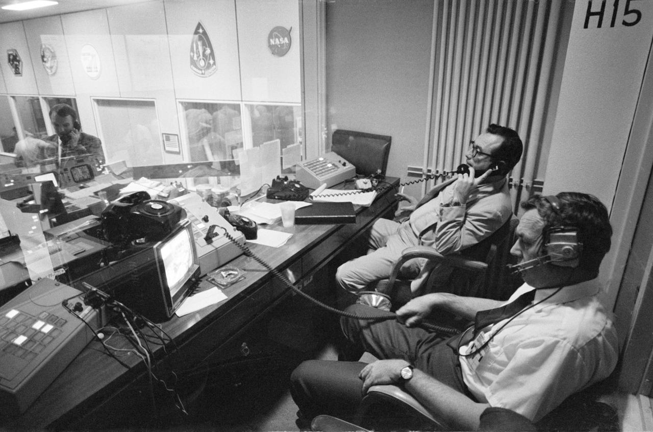
S70-35012 (15 April 1970) --- Two phases of busy activity during critical moments of the Apollo 13 mission are reflected in this view in the Mission Control Center, Building 30, Manned Spacecraft Center. In the foreground, Henry Simmons (left) of Newsweek magazine and John E. Riley, public information specialist, Public Affairs Office, MSC, man their positions in the Press Room. At extreme left of photo, Gerald D. Griffin, Shift 2 flight director, talks on telephone in Mission Operations Control Room. When this photograph was taken, the Apollo 13 lunar landing had been canceled, and the problem-plagued Apollo 13 crewmen were in trans-Earth trajectory attempting to bring their crippled spacecraft back home.
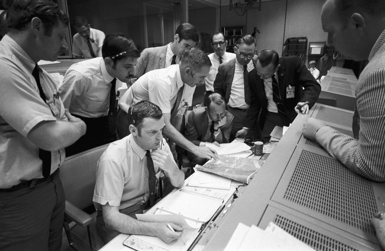
S70-35014 (15 April 1970) --- A group of flight controllers gathers around the console of Glenn S. Lunney (seated, nearest camera), Shift 4 flight director, in the Mission Operations Control Room (MOCR) of Mission Control Center (MCC), located in Building 30 at the Manned Spacecraft Center (MSC). Their attention is drawn to a weather map of the proposed landing site in the South Pacific Ocean. Among those looking on is Dr. Christopher C. Kraft, deputy director, MSC, standing in black suit, on right. When this photograph was taken, the Apollo 13 lunar landing mission had been canceled, and the problem-plagued Apollo 13 crew members were in trans-Earth trajectory attempting to bring their crippled spacecraft back home.
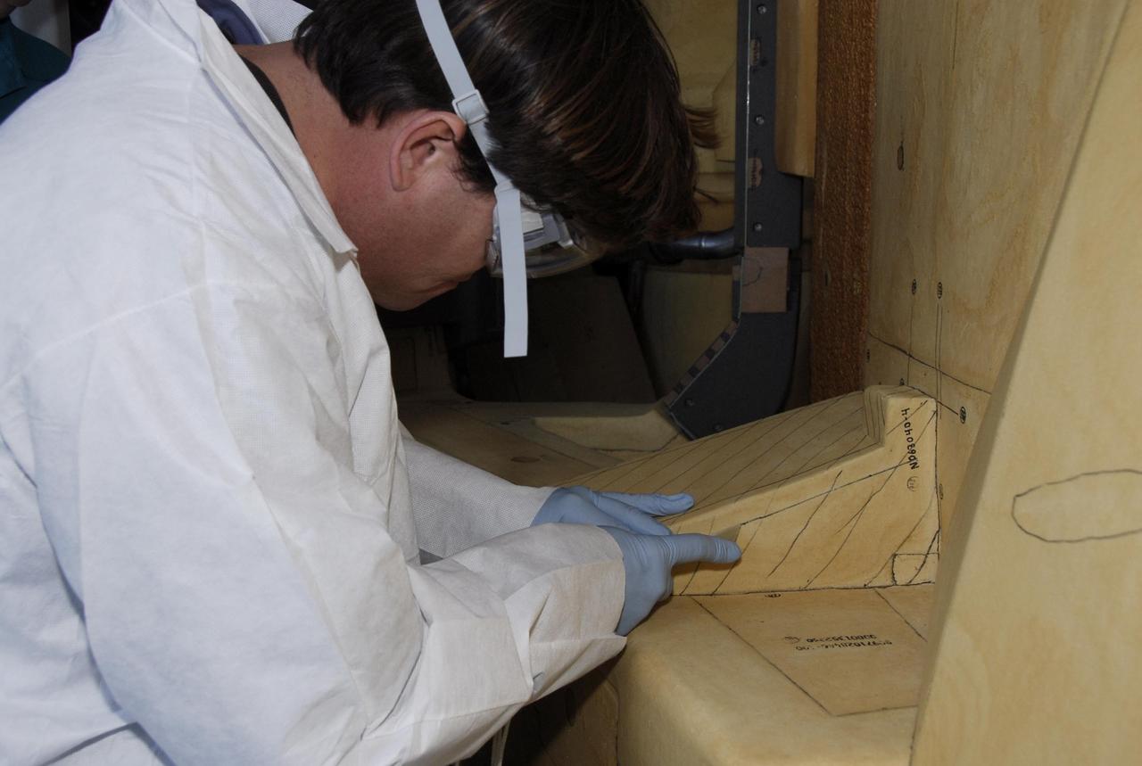
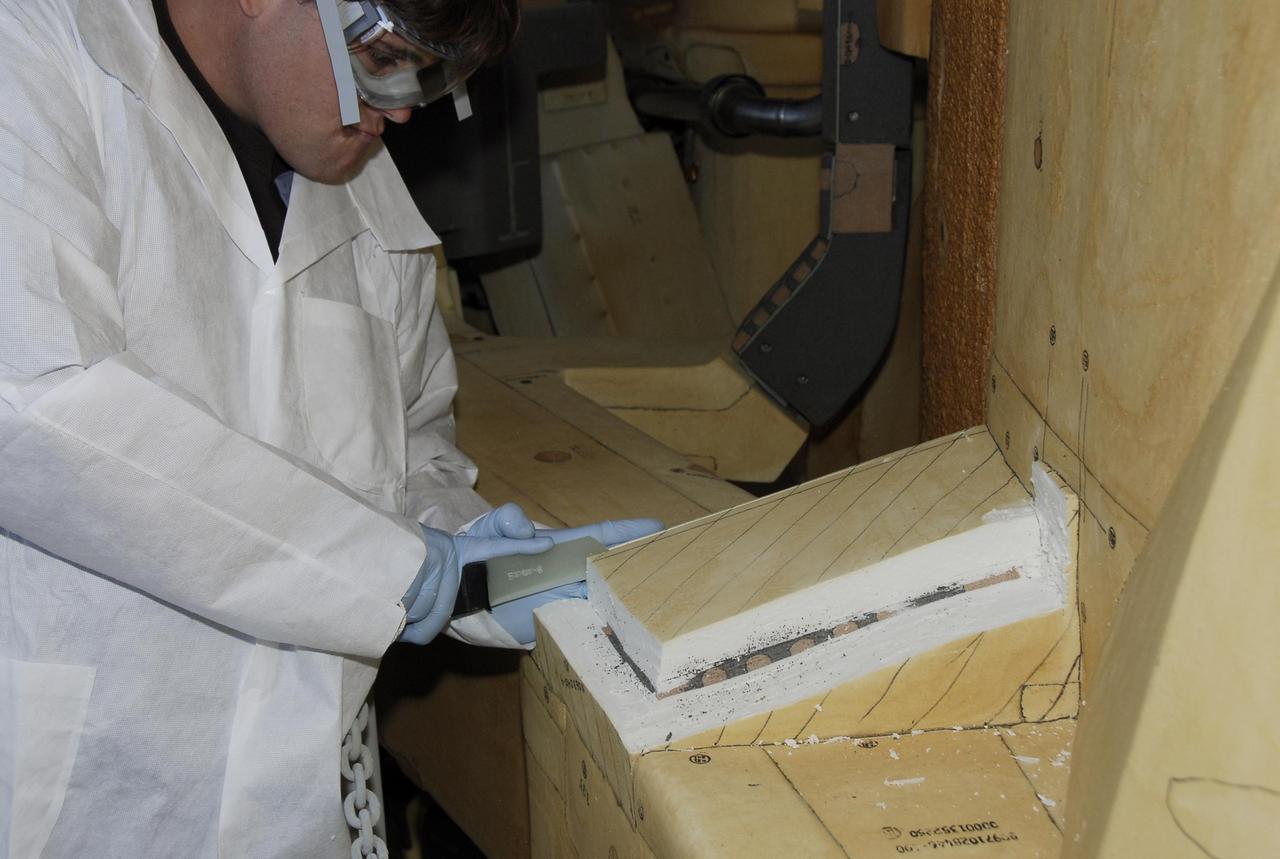
KENNEDY SPACE CENTER, FLA. -- At Launch Pad 39A, a United Space Alliance technician carefully cuts away the foam insulation surrounding the covers over the feed-through connector box on the external tank for space shuttle Atlantis' STS-122 mission. The covers will be removed for access to the feed-through connectors. Following the failure of some of the tank's engine cutoff sensors, or ECO sensors, during propellant tanking for launch attempts on Dec. 6 and Dec. 9, a tanking test was conducted on Dec. 18 to aid in troubleshooting the cause. Technicians spliced test wiring into the ECO sensor electrical system and used time domain reflectometry equipment to help locate the electrical anomaly. Results of the tanking test pointed to an open circuit in the feed-through connector wiring, which is located at the base of the tank. The feed-through connector passes the wires from the inside of the tank to the outside. During the holiday period, workers from Lockheed Martin will begin inspecting and testing the connector. Shuttle program managers will meet on Dec. 27 to review the test and analysis, and decide on a forward plan. Photo credit: NASA/Kim Shiflett
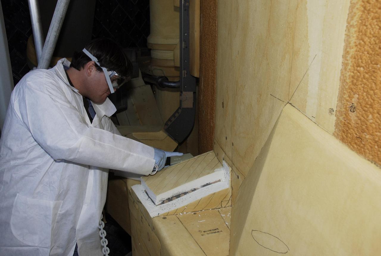
KENNEDY SPACE CENTER, FLA. -- At Launch Pad 39A, a United Space Alliance technician carefully cuts away the foam insulation surrounding the covers over the feed-through connector box on the external tank for space shuttle Atlantis' STS-122 mission, revealing the fastener holes on the covers. The covers will be removed for access to the feed-through connectors. Following the failure of some of the tank's engine cutoff sensors, or ECO sensors, during propellant tanking for launch attempts on Dec. 6 and Dec. 9, a tanking test was conducted on Dec. 18 to aid in troubleshooting the cause. Technicians spliced test wiring into the ECO sensor electrical system and used time domain reflectometry equipment to help locate the electrical anomaly. Results of the tanking test pointed to an open circuit in the feed-through connector wiring, which is located at the base of the tank. The feed-through connector passes the wires from the inside of the tank to the outside. During the holiday period, workers from Lockheed Martin will begin inspecting and testing the connector. Shuttle program managers will meet on Dec. 27 to review the test and analysis, and decide on a forward plan. Photo credit: NASA/Kim Shiflett

KENNEDY SPACE CENTER, FLA. -- At Launch Pad 39A, a United Space Alliance technician removes foam insulation revealing the fastener holes on the covers over the feed-through connector box on the external tank for space shuttle Atlantis' STS-122 mission. The covers will be removed for access to the feed-through connectors. Following the failure of some of the tank's engine cutoff sensors, or ECO sensors, during propellant tanking for launch attempts on Dec. 6 and Dec. 9, a tanking test was conducted on Dec. 18 to aid in troubleshooting the cause. Technicians spliced test wiring into the ECO sensor electrical system and used time domain reflectometry equipment to help locate the electrical anomaly. Results of the tanking test pointed to an open circuit in the feed-through connector wiring, which is located at the base of the tank. The feed-through connector passes the wires from the inside of the tank to the outside. During the holiday period, workers from Lockheed Martin will begin inspecting and testing the connector. Shuttle program managers will meet on Dec. 27 to review the test and analysis, and decide on a forward plan. Photo credit: NASA/Kim Shiflett
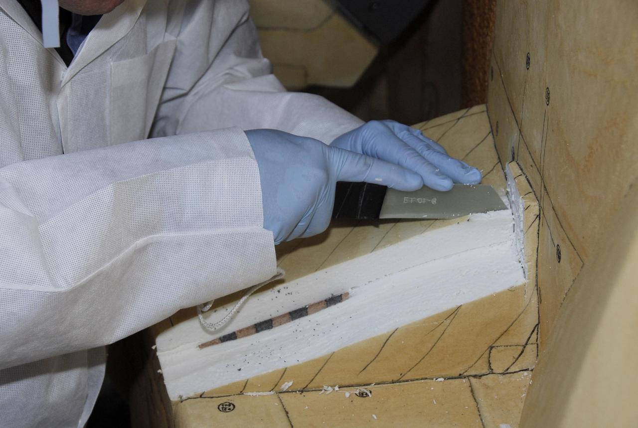
KENNEDY SPACE CENTER, FLA. -- At Launch Pad 39A, the foam insulation surrounding the covers over the feed-through connector box on the external tank for space shuttle Atlantis' STS-122 mission is carefully cut away by a United Space Alliance technician. The covers will be removed for access to the feed-through connectors. Following the failure of some of the tank's engine cutoff sensors, or ECO sensors, during propellant tanking for launch attempts on Dec. 6 and Dec. 9, a tanking test was conducted on Dec. 18 to aid in troubleshooting the cause. Technicians spliced test wiring into the ECO sensor electrical system and used time domain reflectometry equipment to help locate the electrical anomaly. Results of the tanking test pointed to an open circuit in the feed-through connector wiring, which is located at the base of the tank. The feed-through connector passes the wires from the inside of the tank to the outside. During the holiday period, workers from Lockheed Martin will begin inspecting and testing the connector. Shuttle program managers will meet on Dec. 27 to review the test and analysis, and decide on a forward plan. Photo credit: NASA/Kim Shiflett
KENNEDY SPACE CENTER, FLA. -- At Launch Pad 39A, a United Space Alliance technician carefully cuts away the foam insulation surrounding the covers over the feed-through connector box on the external tank for space shuttle Atlantis' STS-122 mission, revealing the fastener holes on the covers. The covers will be removed for access to the feed-through connectors. Following the failure of some of the tank's engine cutoff sensors, or ECO sensors, during propellant tanking for launch attempts on Dec. 6 and Dec. 9, a tanking test was conducted on Dec. 18 to aid in troubleshooting the cause. Technicians spliced test wiring into the ECO sensor electrical system and used time domain reflectometry equipment to help locate the electrical anomaly. Results of the tanking test pointed to an open circuit in the feed-through connector wiring, which is located at the base of the tank. The feed-through connector passes the wires from the inside of the tank to the outside. During the holiday period, workers from Lockheed Martin will begin inspecting and testing the connector. Shuttle program managers will meet on Dec. 27 to review the test and analysis, and decide on a forward plan. Photo credit: NASA/Kim Shiflett

This image depicts a full view of the Earth, taken by the Geostationary Operational Environment Satellite (GOES-8). The red and green charnels represent visible data, while the blue channel represents inverted 11 micron infrared data. The north and south poles were not actually observed by GOES-8. To produce this image, poles were taken from a GOES-7 image. Owned and operated by the National Oceanic and Atmospheric Administration (NOAA), GOES satellites provide the kind of continuous monitoring necessary for intensive data analysis. They circle the Earth in a geosynchronous orbit, which means they orbit the equatorial plane of the Earth at a speed matching the Earth's rotation. This allows them to hover continuously over one position on the surface. The geosynchronous plane is about 35,800 km (22,300 miles) above the Earth, high enough to allow the satellites a full-disc view of the Earth. Because they stay above a fixed spot on the surface, they provide a constant vigil for the atmospheric triggers for severe weather conditions such as tornadoes, flash floods, hail storms, and hurricanes. When these conditions develop, the GOES satellites are able to monitor storm development and track their movements. NASA manages the design and launch of the spacecraft. NASA launched the first GOES for NOAA in 1975 and followed it with another in 1977. Currently, the United States is operating GOES-8, positioned at 75 west longitude and the equator, and GOES-10, which is positioned at 135 west longitude and the equator. (GOES-9, which malfunctioned in 1998, is being stored in orbit as an emergency backup should either GOES-8 or GOES-10 fail. GOES-11 was launched on May 3, 2000 and GOES-12 on July 23, 2001. Both are being stored in orbit as a fully functioning replacement for GOES-8 or GOES-10 on failure.
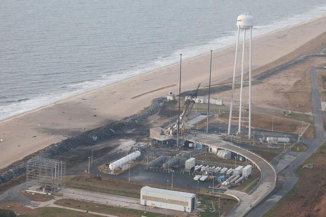
An aerial view of the Wallops Island launch facilities taken by the Wallops Incident Response Team Oct. 29 following the failed launch attempt of Orbital Science Corp.'s Antares rocket Oct. 28. Credit: NASA/Terry Zaperach --- The Wallops Incident Response Team completed today an initial assessment of Wallops Island, Virginia, following the catastrophic failure of Orbital Science Corp.’s Antares rocket shortly after liftoff at 6:22 p.m. EDT Tuesday, Oct. 28, from Pad 0A of the Mid-Atlantic Regional Spaceport at NASA’s Wallops Flight Facility in Virginia. “I want to praise the launch team, range safety, all of our emergency responders and those who provided mutual aid and support on a highly-professional response that ensured the safety of our most important resource -- our people,” said Bill Wrobel, Wallops director. “In the coming days and weeks ahead, we'll continue to assess the damage on the island and begin the process of moving forward to restore our space launch capabilities. There's no doubt in my mind that we will rebound stronger than ever.” The initial assessment is a cursory look; it will take many more weeks to further understand and analyze the full extent of the effects of the event. A number of support buildings in the immediate area have broken windows and imploded doors. A sounding rocket launcher adjacent to the pad, and buildings nearest the pad, suffered the most severe damage. At Pad 0A the initial assessment showed damage to the transporter erector launcher and lightning suppression rods, as well as debris around the pad. The Wallops team also met with a group of state and local officials, including the Virginia Department of Environmental Quality, the Virginia Department of Emergency Management, the Virginia Marine Police, and the U.S. Coast Guard. The Wallops environmental team also is conducting assessments at the site. Preliminary observations are that the environmental effects of the launch failure were largely contained within the southern third of Wallops Island, in the area immediately adjacent to the pad. Immediately after the incident, the Wallops’ industrial hygienist collected air samples at the Wallops mainland area, the Highway 175 causeway, and on Chincoteague Island. No hazardous substances were detected at the sampled locations. Additional air, soil and water samples will be collected from the incident area as well as at control sites for comparative analysis. The Coast Guard and Virginia Marine Resources Commission reported today they have not observed any obvious signs of water pollution, such as oil sheens. Furthermore, initial assessments have not revealed any obvious impacts to fish or wildlife resources. The Incident Response Team continues to monitor and assess. Following the initial assessment, the response team will open the area of Wallops Island, north of the island flagpole opposite of the launch pad location, to allow the U.S. Navy to return back to work. Anyone who finds debris or damage to their property in the vicinity of the launch mishap is cautioned to stay away from it and call the Incident Response Team at 757-824-1295. Further updates on the situation and the progress of the ongoing investigation will be available at: <a href="http://www.orbital.com" rel="nofollow">www.orbital.com</a> and <a href="http://www.nasa.gov/orbital" rel="nofollow">www.nasa.gov/orbital</a> <b><a href="http://www.nasa.gov/audience/formedia/features/MP_Photo_Guidelines.html" rel="nofollow">NASA image use policy.</a></b> <b><a href="http://www.nasa.gov/centers/goddard/home/index.html" rel="nofollow">NASA Goddard Space Flight Center</a></b> enables NASA’s mission through four scientific endeavors: Earth Science, Heliophysics, Solar System Exploration, and Astrophysics. Goddard plays a leading role in NASA’s accomplishments by contributing compelling scientific knowledge to advance the Agency’s mission. <b>Follow us on <a href="http://twitter.com/NASAGoddardPix" rel="nofollow">Twitter</a></b> <b>Like us on <a href="http://www.facebook.com/pages/Greenbelt-MD/NASA-Goddard/395013845897?ref=tsd" rel="nofollow">Facebook</a></b> <b>Find us on <a href="http://instagram.com/nasagoddard?vm=grid" rel="nofollow">Instagram</a></b>