
Sue Grafton, NASA engineer poses in advance of the Flight Dynamic Research Facility's (FDRF) grand opening. Sue started as a researcher for the N.A.C.A. and worked in the vertical spin tunnel (VST). She has since worked in the 30x60 full-scale tunnel for many years before its closure and then returned to VST and 12ft (NASA’s oldest operational wind tunnels). She will also be onboard for the commissioning of the FDRF, NASA’s newest wind tunnel.

Photo of Sue Grafton taken in advance of the Flight Dynamic Research Facility's (FDRF) ribbon cutting. Sue started as a researcher for the N.A.C.A. and worked in the vertical spin tunnel (VST). She has since worked in the 30x60 full-scale tunnel for many years before its closure and then returned to VST and 12ft (NASA’s oldest operational wind tunnels). She will also be onboard for the commissioning of the FDRF, NASA’s newest wind tunnel.
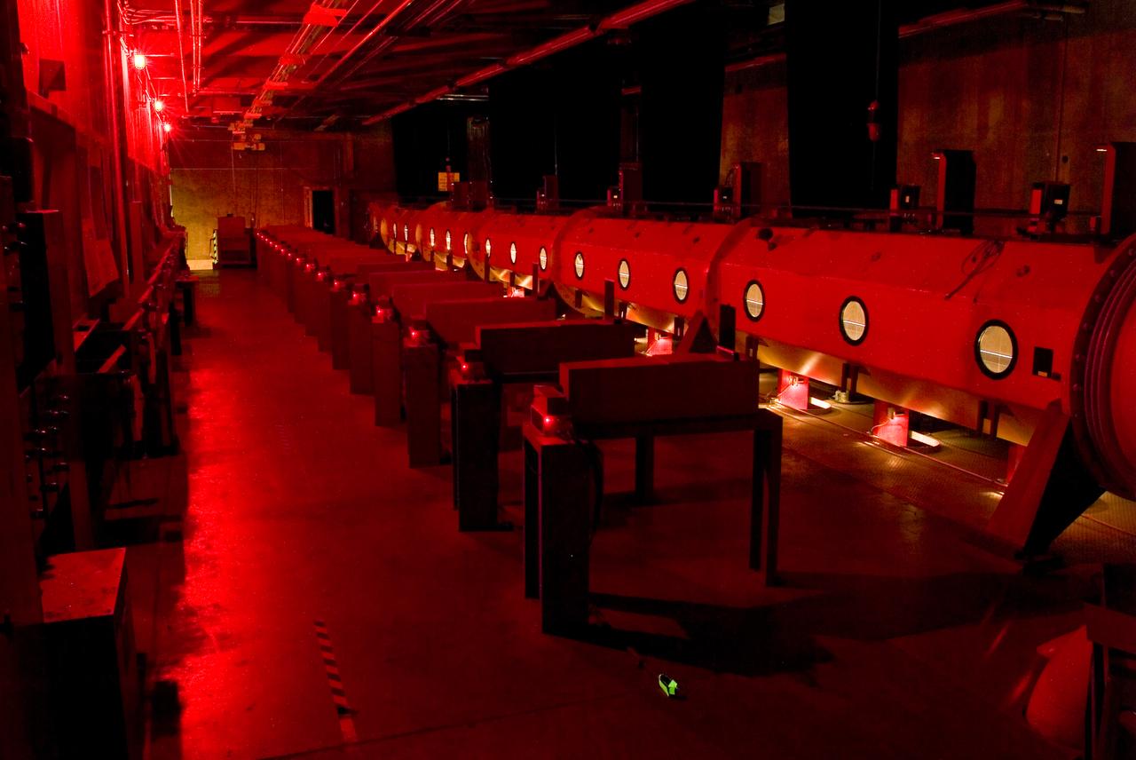
Ames Hypersonic Free Flight Aerodynamic Facility is used for research on gas dynamic problems of atmospheric entry. High relative speeds are achieved by launching models (in sabots if necessary) from high-speed guns into a countercurrent hypersonic air stream (14,000 ft/sec) driven by combustion-powered shock tube.
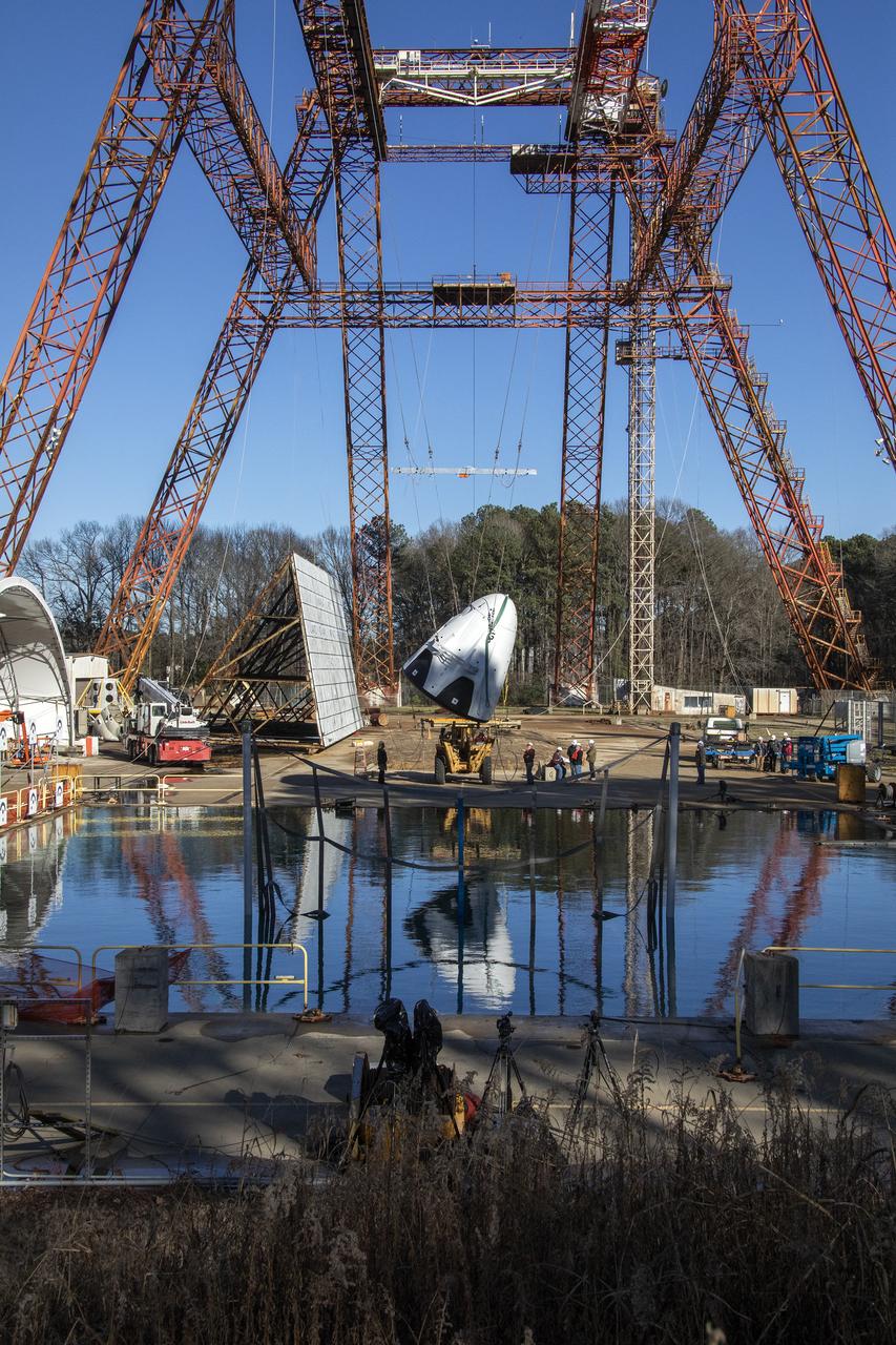
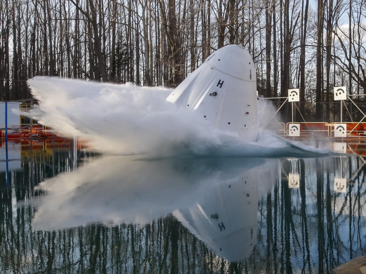
The Space X capsule being tested at NASA Langley’s Splash Test Basin. A series of drop tests into the Hydro Impact Basin at the Landing and Impact Research Facility at NASA’s Langley Research Center in Hampton, Virginia helped SpaceX’s Crew Dragon capsule prepare to safely land astronauts. A mock-up of the capsule with two instrumented crash test devices seated inside was tested in March 2019, representing how the capsule may impact the water during splashdown with different wind and parachute dynamics. Data collected helps understand pressures on the capsule and how those forces affect the spacecraft and occupants. Crew Dragon will carry NASA astronauts Bob Behnken and Doug Hurley to the International Space Station in the Demo-2 mission, the final SpaceX flight test for NASA’s Commercial Crew Program and the first flight of astronauts to orbit from U.S. soil since the space shuttle’s retirement in 2011. (NASA/ David C. Bowman)
The Space X capsule being tested at NASA Langley’s Splash Test Basin. A series of drop tests into the Hydro Impact Basin at the Landing and Impact Research Facility at NASA’s Langley Research Center in Hampton, Virginia helped SpaceX’s Crew Dragon capsule prepare to safely land astronauts. A mock-up of the capsule with two instrumented crash test devices seated inside was tested in March 2019, representing how the capsule may impact the water during splashdown with different wind and parachute dynamics. Data collected helps understand pressures on the capsule and how those forces affect the spacecraft and occupants. Crew Dragon will carry NASA astronauts Bob Behnken and Doug Hurley to the International Space Station in the Demo-2 mission, the final SpaceX flight test for NASA’s Commercial Crew Program and the first flight of astronauts to orbit from U.S. soil since the space shuttle’s retirement in 2011. (NASA/ David C. Bowman)
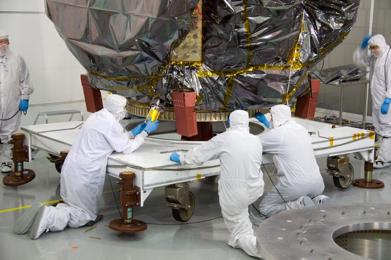
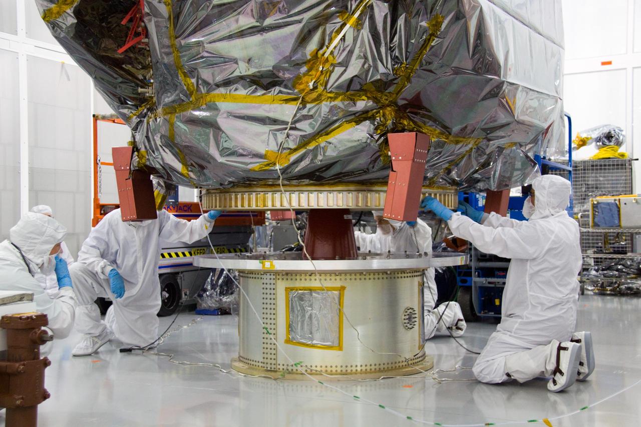
CAPE CANAVERAL, Fla. – At the Astrotech Space Operations facility in Titusville, Fla., NASA Goddard Space Flight Center technician Carl Clause, second from left, installs an aft omni coupler on the bagged Solar Dynamics Observatory, or SDO. SDO is the first space weather research network mission in NASA's Living With a Star Program. The spacecraft's long-term measurements will give solar scientists in-depth information about changes in the sun's magnetic field and insight into how they affect Earth. Liftoff on an Atlas V rocket is scheduled for Feb. 3, 2010. For information on SDO, visit http://www.nasa.gov/sdo. Photo credit: NASA/Troy Cryder
CAPE CANAVERAL, Fla. – At the Astrotech Space Operations facility in Titusville, Fla., technicians from NASA's Goddard Space Flight Center prepare to lift the bagged Solar Dynamics Observatory, or SDO, onto a dolly for further processing. SDO is the first space weather research network mission in NASA's Living With a Star Program. The spacecraft's long-term measurements will give solar scientists in-depth information about changes in the sun's magnetic field and insight into how they affect Earth. Liftoff on an Atlas V rocket is scheduled for Feb. 3, 2010. For information on SDO, visit http://www.nasa.gov/sdo. Photo credit: NASA/Troy Cryder
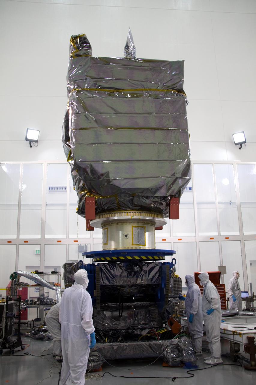
CAPE CANAVERAL, Fla. – At the Astrotech Space Operations facility in Titusville, Fla., technicians from NASA's Goddard Space Flight Center rotate the bagged Solar Dynamics Observatory, or SDO, secured to a Ransome table, into a vertical position. SDO is the first space weather research network mission in NASA's Living With a Star Program. The spacecraft's long-term measurements will give solar scientists in-depth information about changes in the sun's magnetic field and insight into how they affect Earth. Liftoff on an Atlas V rocket is scheduled for Feb. 3, 2010. For information on SDO, visit http://www.nasa.gov/sdo. Photo credit: NASA/Troy Cryder

CAPE CANAVERAL, Fla. – At the Astrotech Space Operations facility in Titusville, Fla., technicians from NASA's Goddard Space Flight Center secure the bagged Solar Dynamics Observatory, or SDO, onto a dolly for further processing. SDO is the first space weather research network mission in NASA's Living With a Star Program. The spacecraft's long-term measurements will give solar scientists in-depth information about changes in the sun's magnetic field and insight into how they affect Earth. Liftoff on an Atlas V rocket is scheduled for Feb. 3, 2010. For information on SDO, visit http://www.nasa.gov/sdo. Photo credit: NASA/Troy Cryder
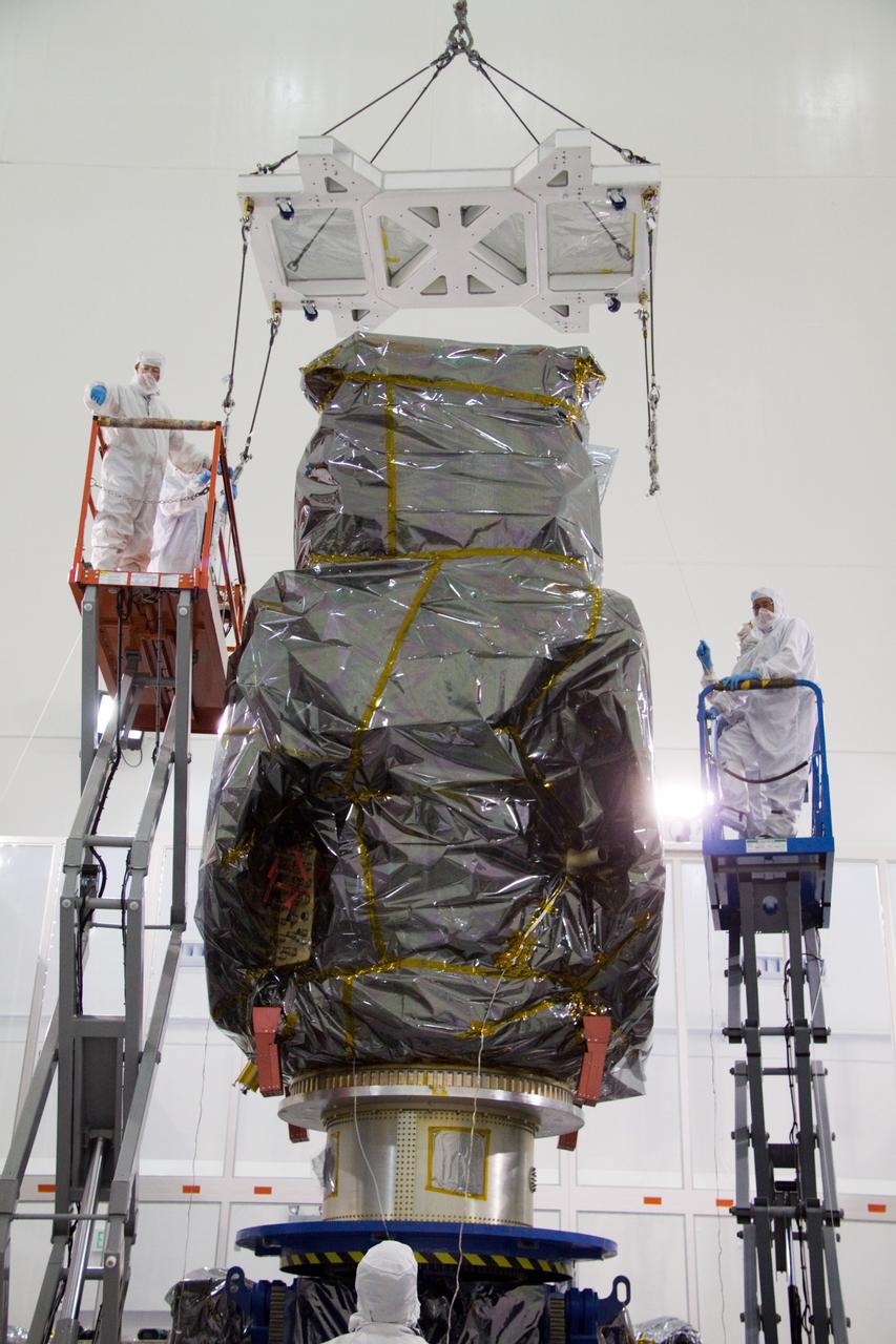
CAPE CANAVERAL, Fla. – At the Astrotech Space Operations facility in Titusville, Fla., technicians from NASA's Goddard Space Flight Center attach a lifting device to the bagged Solar Dynamics Observatory, or SDO, during preparations to remove it from a Ransome table. SDO is the first space weather research network mission in NASA's Living With a Star Program. The spacecraft's long-term measurements will give solar scientists in-depth information about changes in the sun's magnetic field and insight into how they affect Earth. Liftoff on an Atlas V rocket is scheduled for Feb. 3, 2010. For information on SDO, visit http://www.nasa.gov/sdo. Photo credit: NASA/Troy Cryder
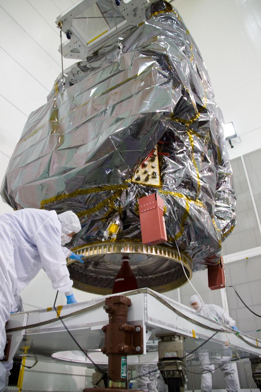
CAPE CANAVERAL, Fla. – At the Astrotech Space Operations facility in Titusville, Fla., technicians from NASA's Goddard Space Flight Center lower the bagged Solar Dynamics Observatory, or SDO, onto a dolly for further processing. SDO is the first space weather research network mission in NASA's Living With a Star Program. The spacecraft's long-term measurements will give solar scientists in-depth information about changes in the sun's magnetic field and insight into how they affect Earth. Liftoff on an Atlas V rocket is scheduled for Feb. 3, 2010. For information on SDO, visit http://www.nasa.gov/sdo. Photo credit: NASA/Troy Cryder
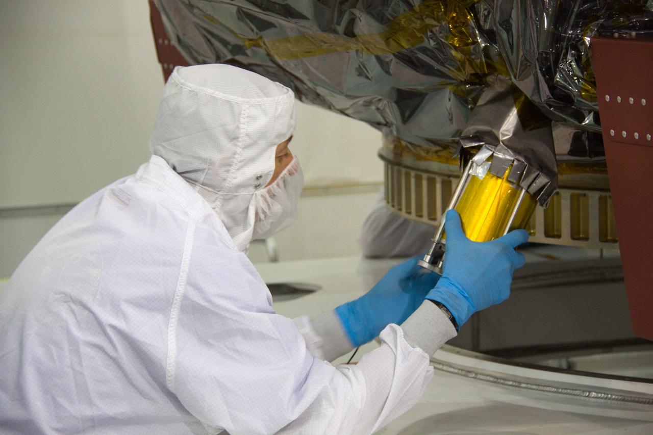
CAPE CANAVERAL, Fla. – At the Astrotech Space Operations facility in Titusville, Fla., NASA Goddard Space Flight Center technician Carl Clause installs an aft omni coupler on the bagged Solar Dynamics Observatory, or SDO. SDO is the first space weather research network mission in NASA's Living With a Star Program. The spacecraft's long-term measurements will give solar scientists in-depth information about changes in the sun's magnetic field and insight into how they affect Earth. Liftoff on an Atlas V rocket is scheduled for Feb. 3, 2010. For information on SDO, visit http://www.nasa.gov/sdo. Photo credit: NASA/Troy Cryder
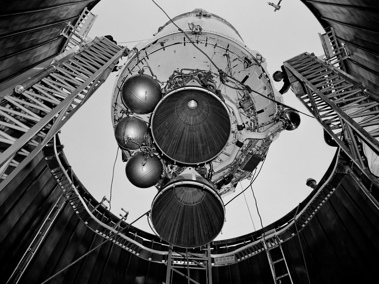
A Centaur second-stage rocket is lowered into the vacuum tank inside the Space Power Chambers at NASA’s Lewis Research Center. Centaur was to be paired with an Atlas booster to send the Surveyor spacecraft to the moon as a precursor to the Apollo landings. Lewis was assigned responsibility for the Centaur Program after the failure of its first developmental flight in May 1962. Lewis’ Altitude Wind Tunnel was converted into two large test chambers—the Space Power Chambers. The facility’s vacuum chamber, seen here, allowed the Centaur to be stood up vertically and subjected to atmospheric conditions-- pressures, temperature, and radiation--similar to those it would encounter in space. The Centaur for these tests was delivered to Cleveland in a C‒130 aircraft on September 27, 1963. The rocket was set up in the facility’s high bay where Lewis technicians and General Dynamics consultants updated its flight systems to match the upcoming Atlas-Centaur‒4 mission. Months were spent reharnessing the Centaur’s electronics, learning about the systems, and being taught how to handle flight hardware. By early spring 1964, the extensive setup of both the spacecraft and the chamber was finally completed. On March 19 the Centaur was rolled out from the shop, hoisted high into the air by a crane, and lowered into the waiting space tank. Researchers were able to verify that the Centaur’s electronics and electrical systems functioned reliably in a space environment.
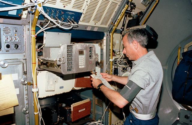
The first United States Microgravity Laboratory (USML-1) was one of NASA's science and technology programs and provided scientists an opportunity to research various scientific investigations in a weightless environment inside the Spacelab module. It also provided demonstrations of new equipment to help prepare for advanced microgravity research and processing aboard the Space Station. The USML-1 flew in orbit for extended periods, providing greater opportunities for research in materials science, fluid dynamics, biotechnology, and combustion science. In this photograph, astronaut Carl Meade is reviewing the manual to activate the Generic Bioprocessing Apparatus (GBA) inside the Spacelab module. The GBA for the USML-1 mission was a multipurpose facility that could help us answer important questions about the relationship between gravity and biology. This unique facility allowed scientists to study biological processes in samples ranging from molecules to small organisms. For example, scientists would examine how collagen, a protein substance found in cornective tissue, bones, and cartilage, forms fibers. In microgravity, it might be possible to alter collagen fiber assembly so that this material could be used more effectively as artificial skin, blood vessels, and other parts of the body. The USML-1 was managed by the Marshall Space Flight Center and waslaunched aboard the Space Shuttle Orbiter Columbia (STS-50) on June 25, 1992.
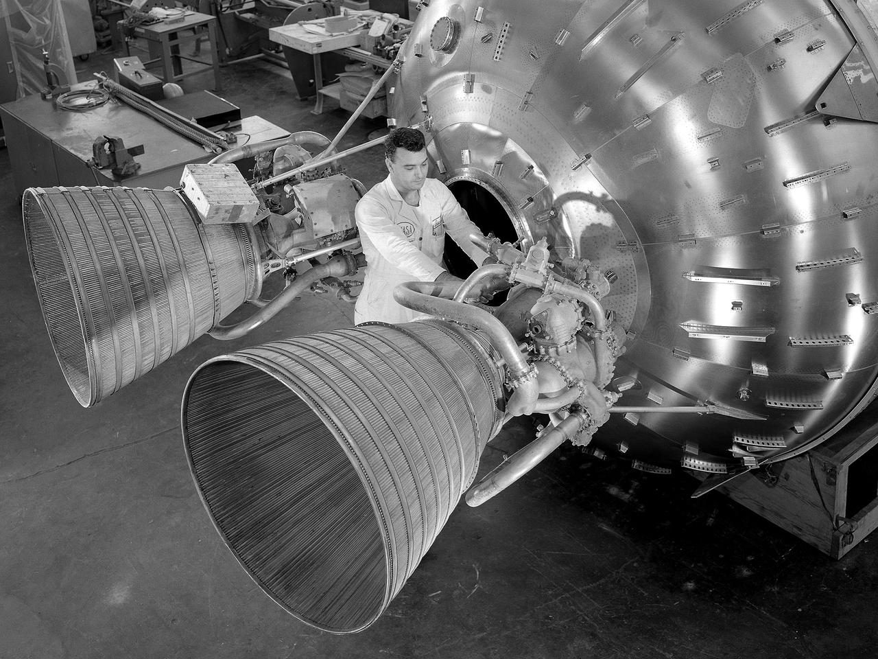
A researcher prepares a Centaur 6A second-stage rocket for a series of tests in the Space Power Chambers’ vacuum tank at the National Aeronautics and Space Administration (NASA) Lewis Research Center. Lewis was assigned oversight of the Centaur Program in the fall of 1962. Prior to that, Centaur’s only launch had failed shortly after liftoff. Lewis engineers undertook an expansive effort to quickly resolve Centaur’s problems and prepare it for its planned missions to send Surveyor spacecraft to land on the moon. For one test program, a complete Centaur vehicle was lowered into the vacuum chamber at the Space Power Chambers to verify that its electronics and electrical systems functioned reliably in a space environment. At the time, electronic malfunctions were one of the most likely causes of failures in space. Studying these systems during long soaks inside the space tank helped the Lewis team calibrate them and facilitate the monitoring of the spacecraft during an actual flight. The Centaur for the tests was delivered to Cleveland in a C-130 aircraft on September 27, 1963. The rocket was set up in the facility’s high bay where Lewis technicians and General Dynamics consultants updated its flight systems to match the upcoming Atlas-Centaur-4 mission, as seen in this photograph.
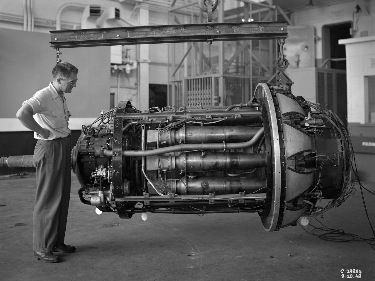
A 3670-horsepower Armstrong-Siddeley Python turboprop being prepared for tests in the Altitude Wind Tunnel at the National Advisory Committee for Aeronautics (NACA) Lewis Flight Propulsion Laboratory. In 1947 Lewis researcher Walter Olsen led a group of representatives from the military, industry, and the NACA on a fact finding mission to investigate the technological progress of British turbojet manufacturers. Afterwards several British engines, including the Python, were brought to Cleveland for testing in Lewis’s altitude facilities. The Python was a 14-stage axial-flow compressor turboprop with a fixed-area nozzle and contra-rotating propellers. Early turboprops combined the turbojet and piston engine technologies. They could move large quantities of air so required less engine speed and thus less fuel. This was very appealing to the military for some applications. The military asked the NACA to compare the Python’s performance at sea to that at high altitudes. The NACA researchers studied the Python in the Altitude Wind Tunnel from July 1949 through January 1950. It was the first time the tunnel was used to study an engine with the sole purpose of learning about, not improving it. They analyzed the engine’s dynamic response using a frequency response method at altitudes between 10,000 to 30,000 feet. Lewis researchers found that they could predict the dynamic response characteristics at any altitude from the data obtained from any other specific altitude. This portion of the testing was completed during a single test run.
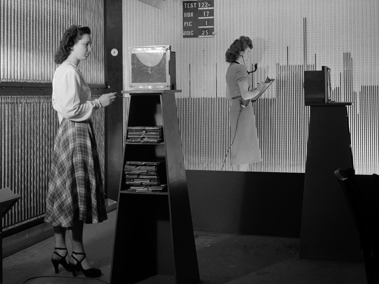
Female computers at the National Advisory Committee for Aeronautics (NACA) Lewis Flight Propulsion Laboratory copy pressure readings from rows of manometers below the 18- by 18-inch Supersonic Wind Tunnel. The computers obtained test data from the manometers and other instruments, made the initial computations, and plotted the information graphically. Based on these computations, the researchers planned their next test or summarized their findings in a report. Manometers were mercury-filled glass tubes that were used to indicate different pressure levels from inside the test facility or from the test article. Manometers look and function very similarly to thermometers. Dozens of pressure sensing instruments were installed for each test. Each was connected to a manometer tube located inside the control room. The mercury inside the manometer rose and fell with the pressure levels. The dark mercury can be seen in this photograph at different levels within the tubes. Since this activity was dynamic, it was necessary to note the levels at given points during the test. This was done using both computer notations and photography.
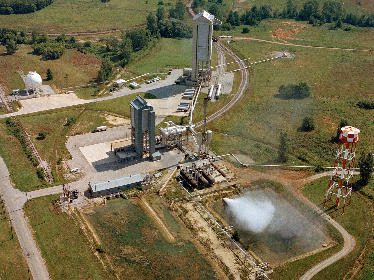
Operation of the High Energy Rocket Engine Research Facility (B-1), left, and Nuclear Rocket Dynamics and Control Facility (B-3) at the National Aeronautics and Space Administration’s (NASA) Plum Brook Station in Sandusky, Ohio. The test stands were constructed in the early 1960s to test full-scale liquid hydrogen fuel systems in simulated altitude conditions. Over the next decade each stand was used for two major series of liquid hydrogen rocket tests: the Nuclear Engine for Rocket Vehicle Application (NERVA) and the Centaur second-stage rocket program. The different components of these rocket engines could be studied under flight conditions and adjusted without having to fire the engine. Once the preliminary studies were complete, the entire engine could be fired in larger facilities. The test stands were vertical towers with cryogenic fuel and steam ejector systems. B-1 was 135 feet tall, and B-3 was 210 feet tall. Each test stand had several levels, a test section, and ground floor shop areas. The test stands relied on an array of support buildings to conduct their tests, including a control building, steam exhaust system, and fuel storage and pumping facilities. A large steam-powered altitude exhaust system reduced the pressure at the exhaust nozzle exit of each test stand. This allowed B-1 and B-3 to test turbopump performance in conditions that matched the altitudes of space.