
Trough Floor
Scalloped Floor
The Floor Is Lava!

A Crack in the Floor
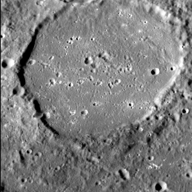
Antoniadi Floor
Valley Floor
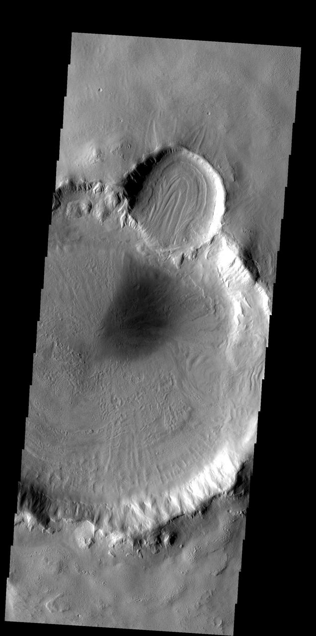
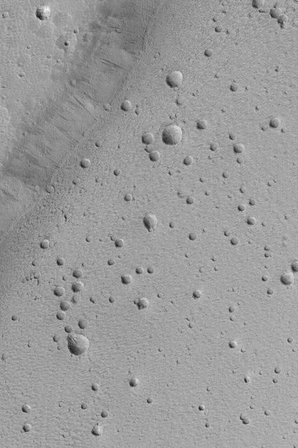
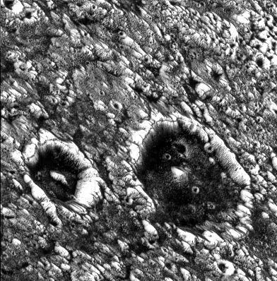
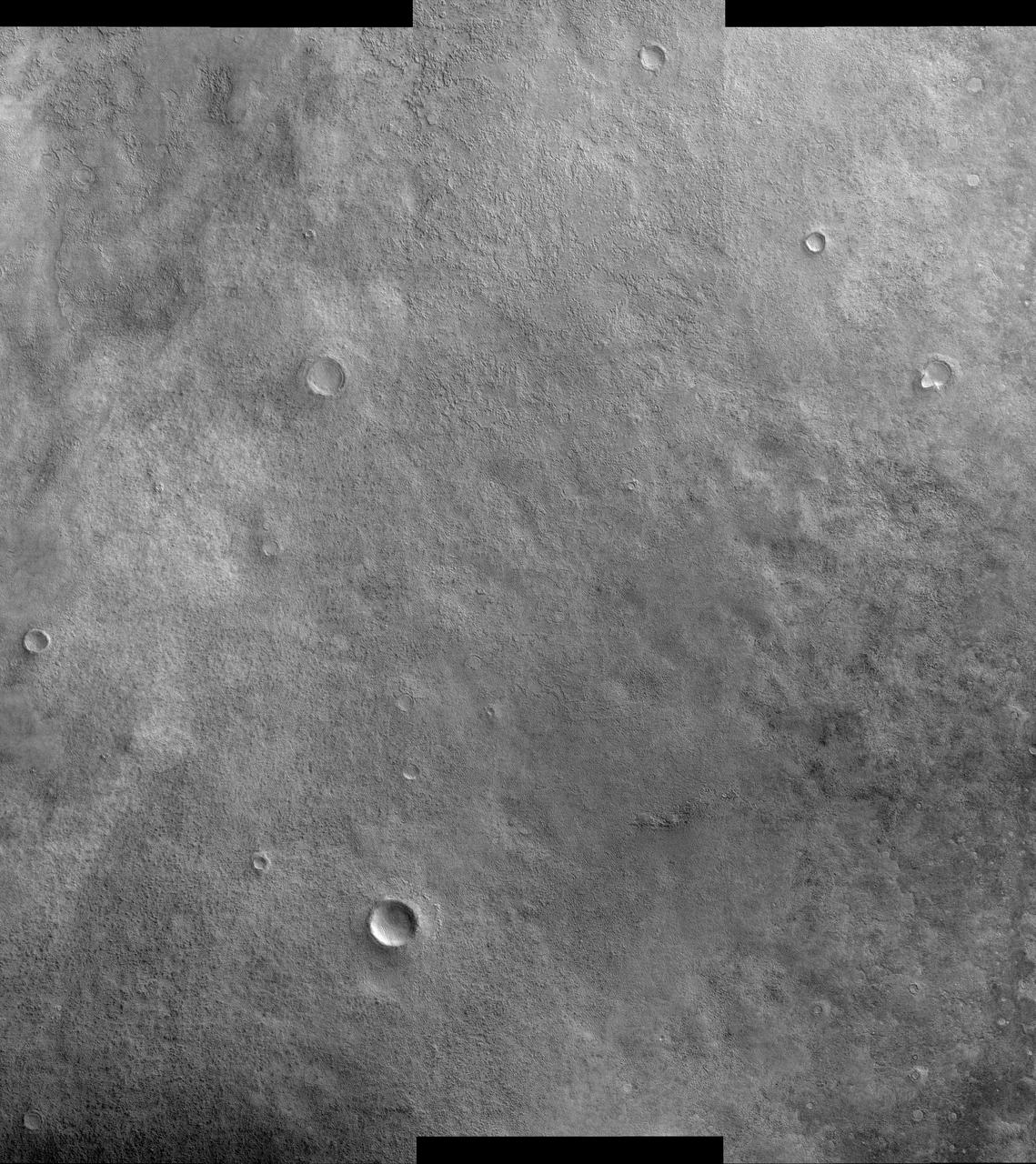
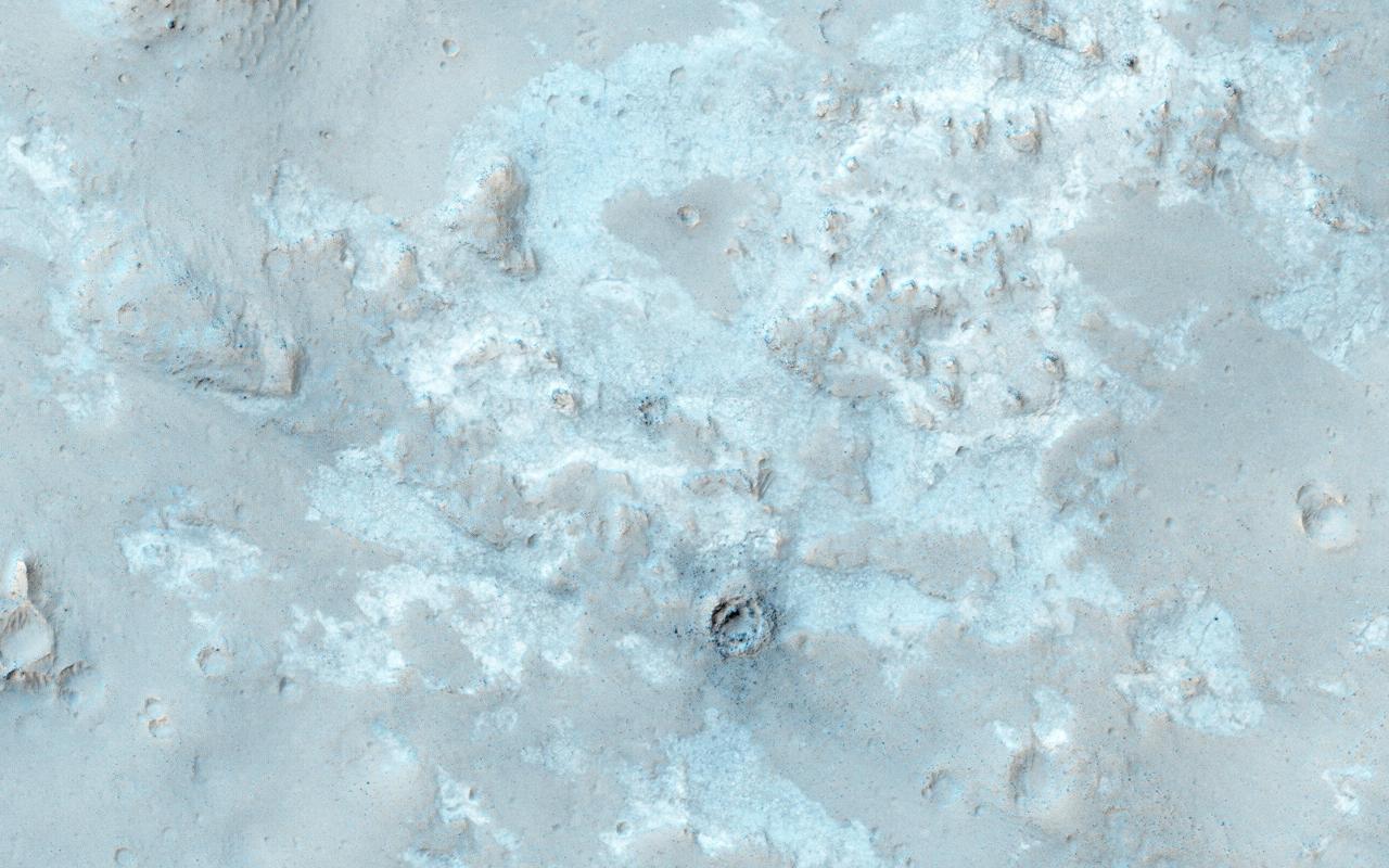
The patterns on the floor of these craters indicates that a volitile, such as ice, likely was present in the floor material
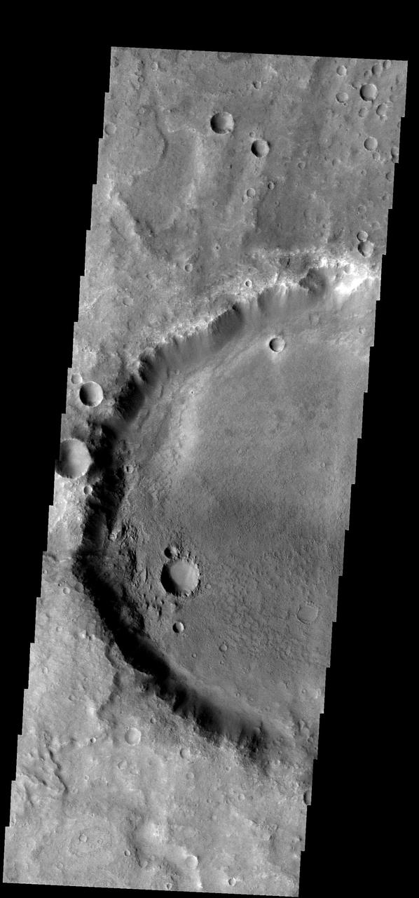
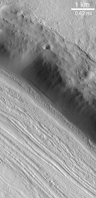
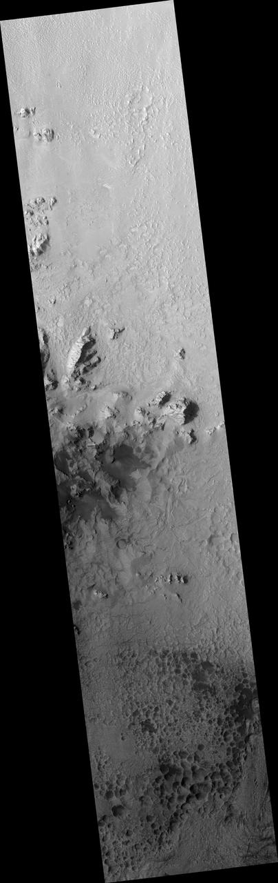
The floor of this crater near its southwestern rim is rougher that the rest of the crater floor. Some process of change is working only in this area
Crater Floor Bands
Floor of Becquerel Crater

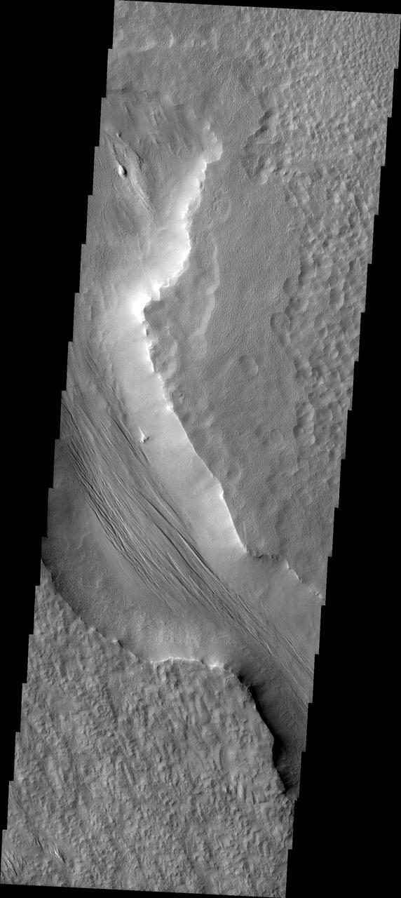
Melas Chasma Floor
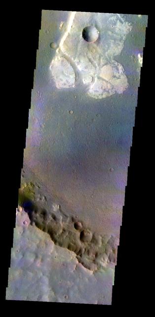
Crater Floor in Color
Crater Floor Dune Field
Floor of Ius Chasma

Melas Chasma Floor
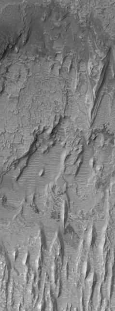
Crater Floor Yardangs
Ceraunius Caldera Floor
Lineated Valley Floor
Watch Out! The Floor Hollow!
Mesas on Depression Floor
Channel Floor Yardangs
Smooth Floor in Copernicus Crater
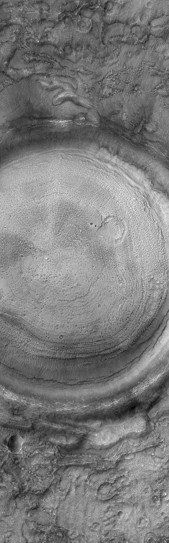
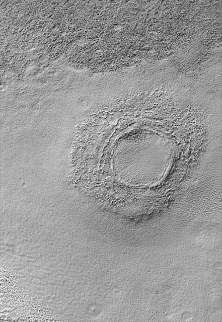
Concentric Crater Floor
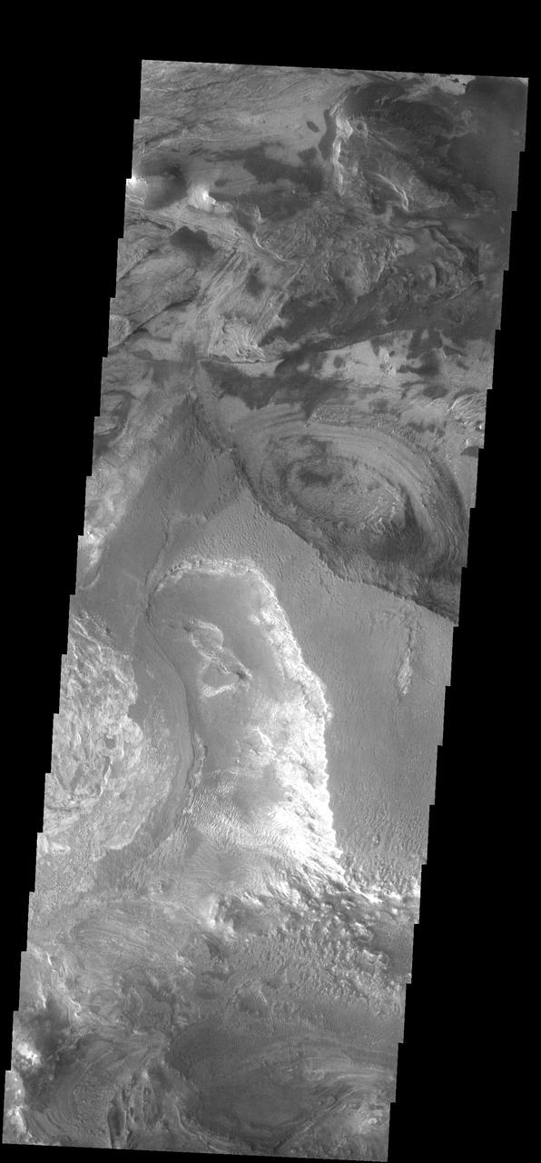
Candor Chasma Floor
Light Outcrop on Crater Floor
Floor of Kasei Valles
Necho Jumbled Floor
Stripped Crater Floor
Flow Along Valley Floors

Ius Chasma Floor
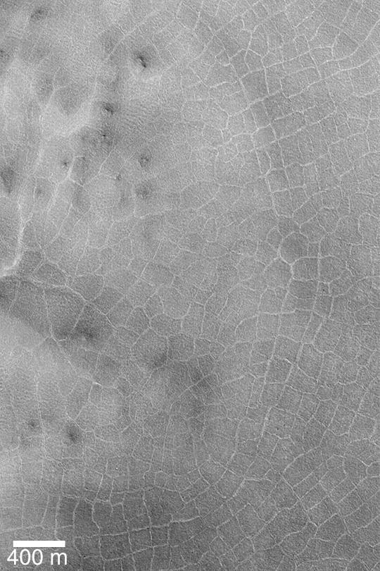
Polygons on Crater Floor
Floor of Noctus Labyrnthus
Sand Sheet on Crater Floor
Fretted Terrain Valley Floor
Mantling Material on Crater Floor
Floor of Chia Crater
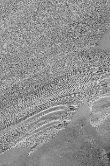
Reull Vallis Floor
Sculpted Rim and Floor
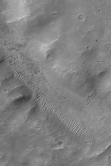
Rippled Valley Floor
Floor of Alexey Tolstoy Crater
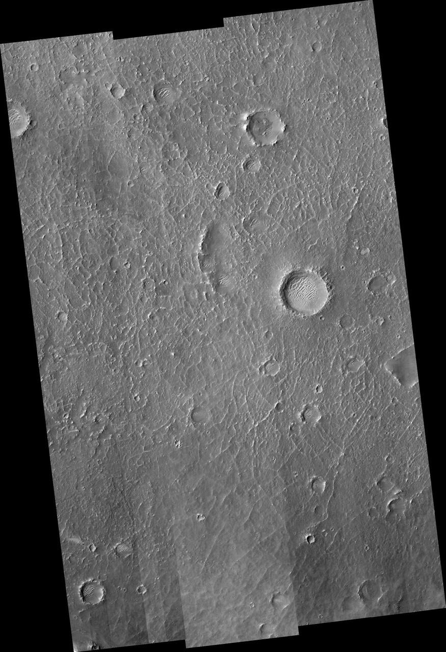
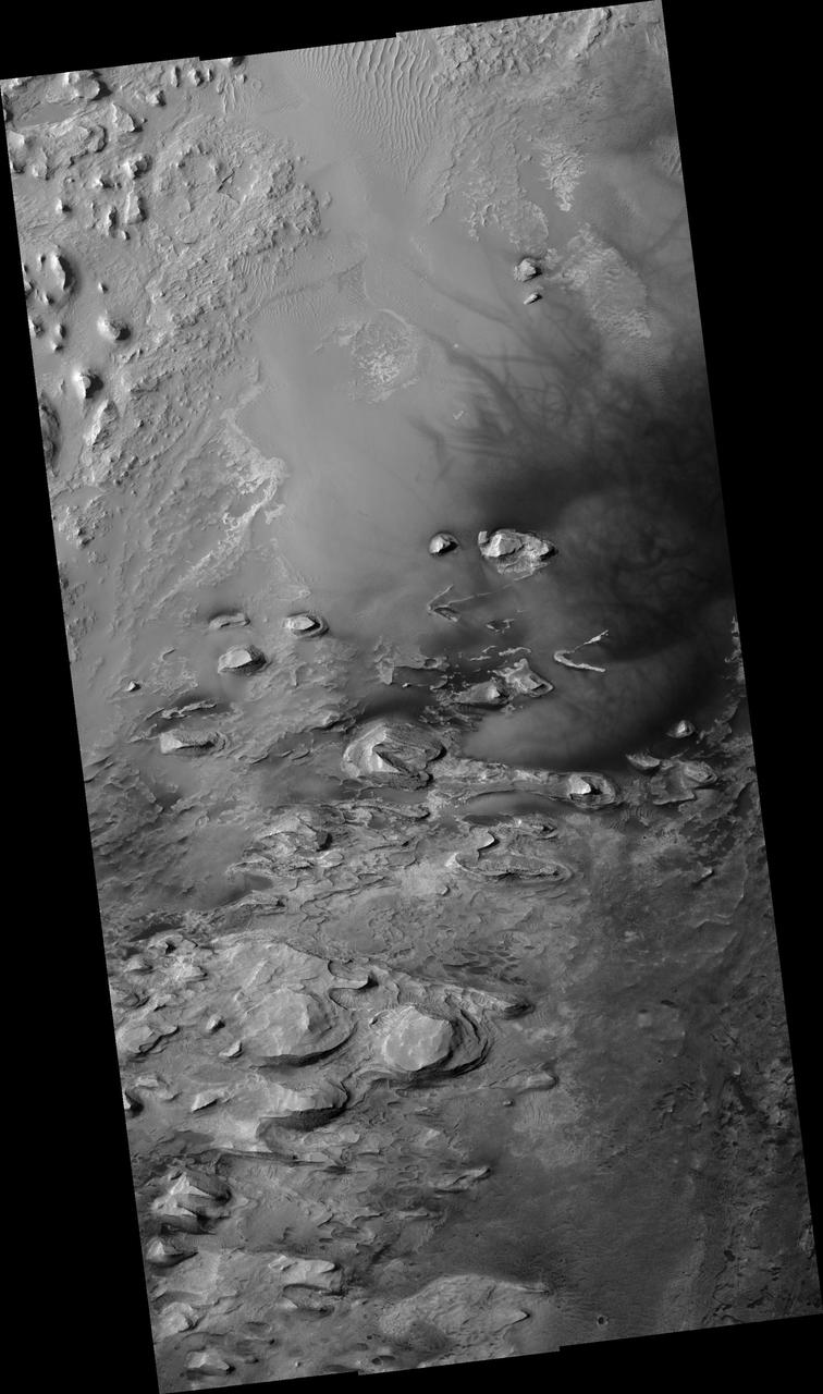
This crater and its interesting floor features is located south of Meridiani Terra
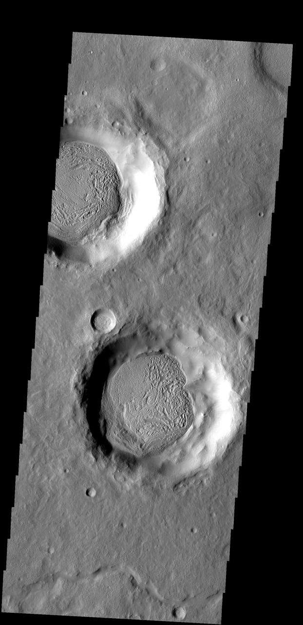
The material covering the floors of these two craters looks very different from the surrounds. The unusual markings of the floor material indicates that a volatile, such as ice, has affected the appearance of the surface
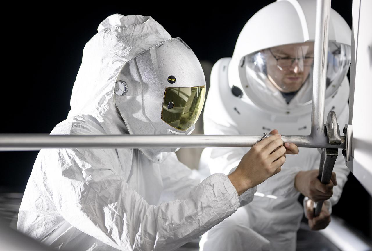
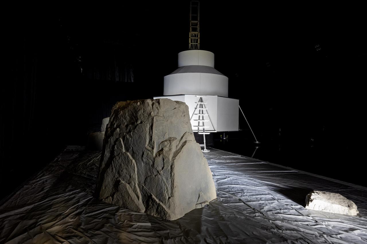
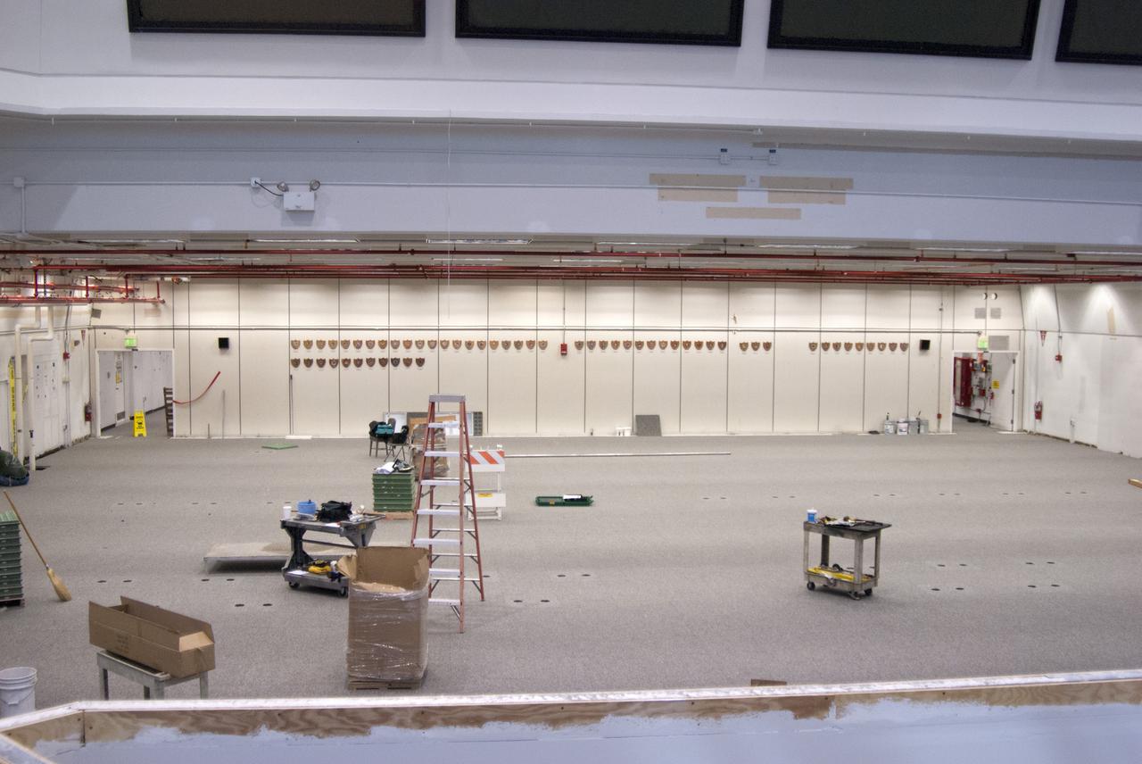
These photos show how teams at NASA’s Marshall Space Flight Center in Huntsville, Alabama, are using the Flat Floor Facility (Building 4619) to understand the lunar lighting environment in preparation for the Artemis III crewed lunar landing mission, slated for 2027. The Flat Floor Facility is an air-bearing floor, providing full-scale simulation capabilities for lunar surface systems by simulating zero gravity in two dimensions. Wearing low-fidelity materials, test engineers can understand how the extreme lighting of the Moon’s South Pole could affect surface operations during Artemis III. High-intensity lights are positioned at a low angle to replicate the strong shadows that are cast across the lunar South Pole by the Sun. Data and analysis from testing at NASA Marshall are improving models Artemis astronauts will use in preparation for lander and surface operations on the Moon during Artemis III. Testing in the facility is also helping cross-agency teams evaluate various tools astronauts may use. NASA Marshall manages the Human Landing System (HLS) Program. For more information, contact NASA Marshall’s Office of Communications at 256-544-0034.
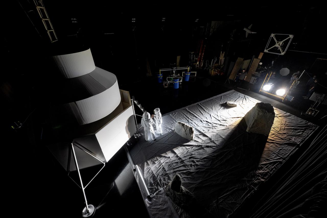
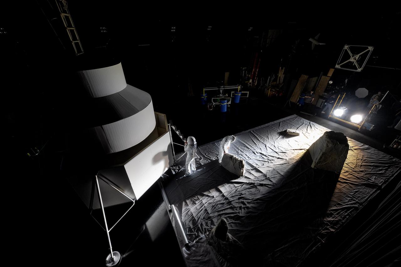
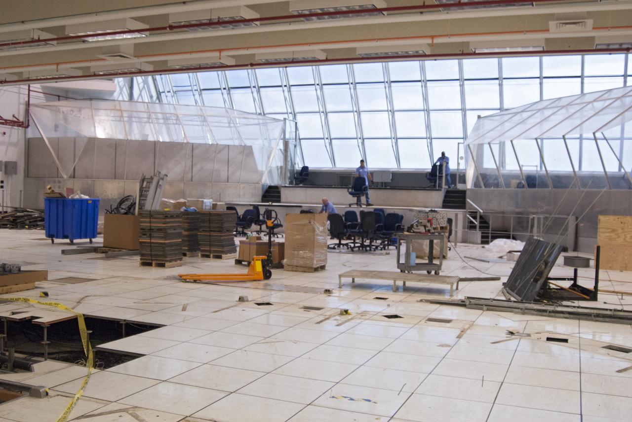
These photos show how teams at NASA’s Marshall Space Flight Center in Huntsville, Alabama, are using the Flat Floor Facility (Building 4619) to understand the lunar lighting environment in preparation for the Artemis III crewed lunar landing mission, slated for 2027. The Flat Floor Facility is an air-bearing floor, providing full-scale simulation capabilities for lunar surface systems by simulating zero gravity in two dimensions. Wearing low-fidelity materials, test engineers can understand how the extreme lighting of the Moon’s South Pole could affect surface operations during Artemis III. High-intensity lights are positioned at a low angle to replicate the strong shadows that are cast across the lunar South Pole by the Sun. Data and analysis from testing at NASA Marshall are improving models Artemis astronauts will use in preparation for lander and surface operations on the Moon during Artemis III. Testing in the facility is also helping cross-agency teams evaluate various tools astronauts may use. NASA Marshall manages the Human Landing System (HLS) Program. For more information, contact NASA Marshall’s Office of Communications at 256-544-0034.
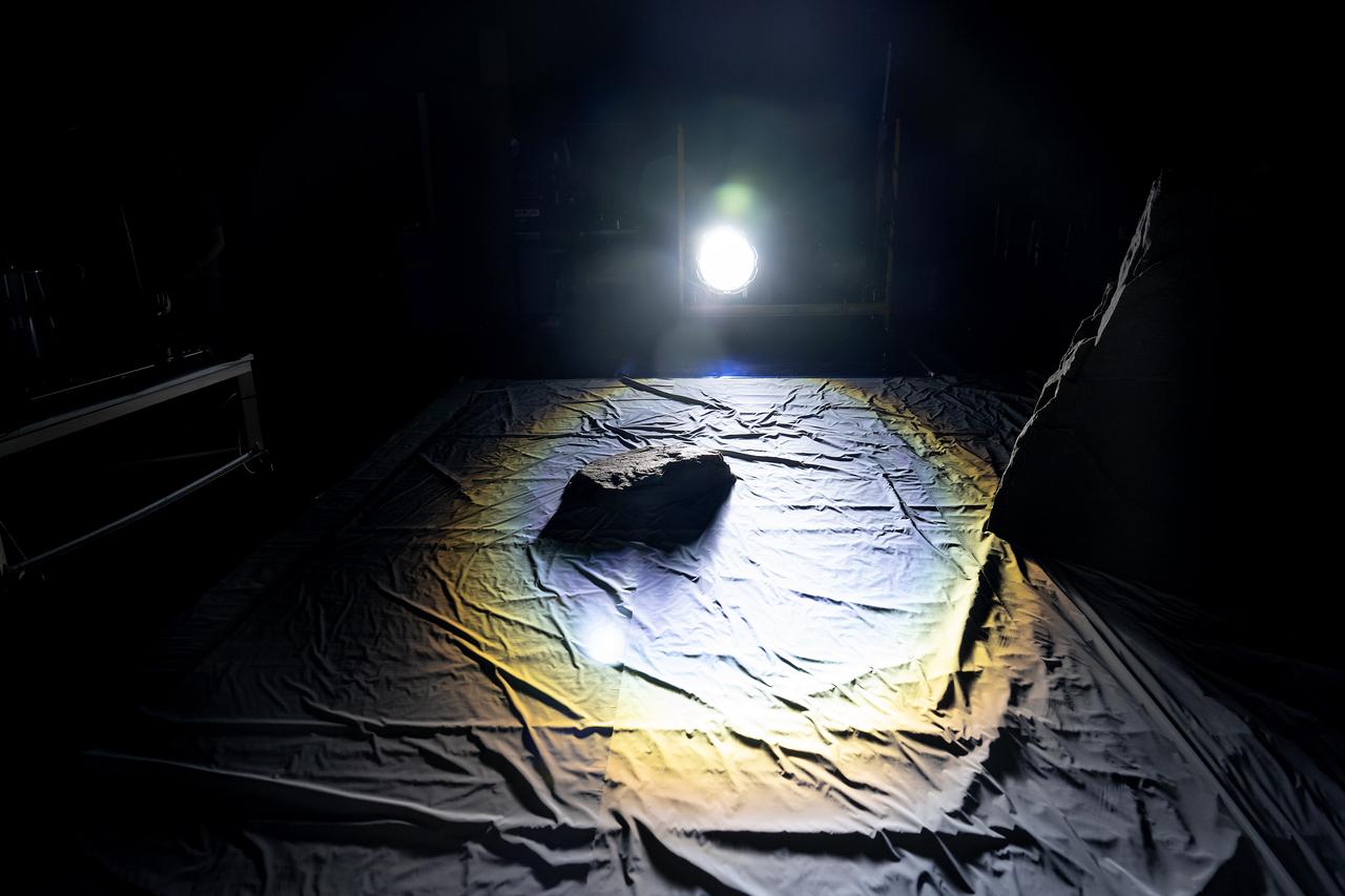
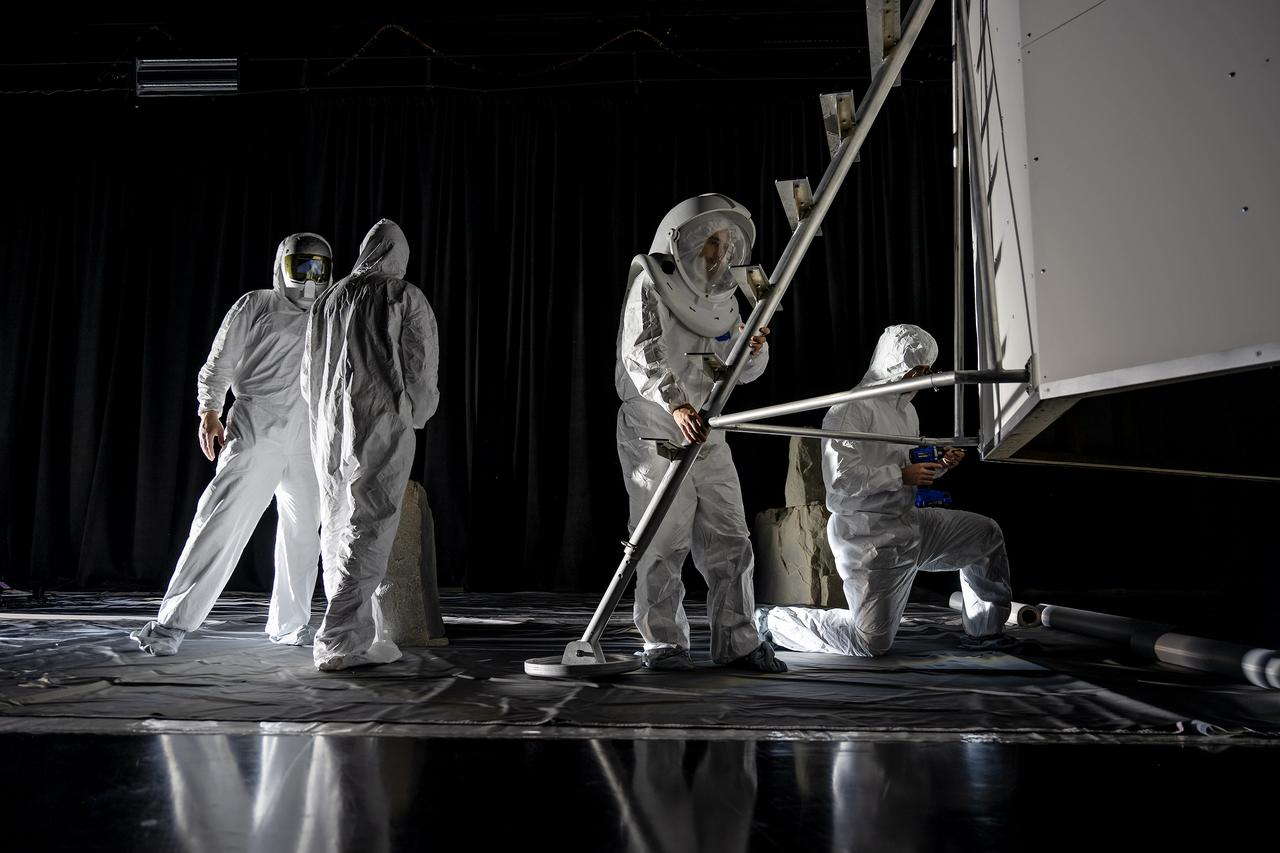
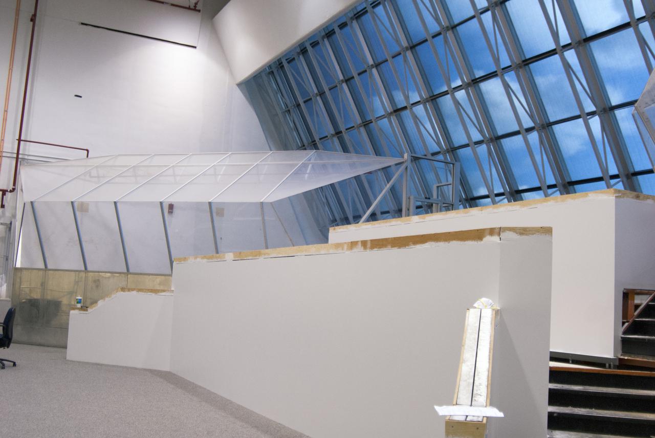
These photos show how teams at NASA’s Marshall Space Flight Center in Huntsville, Alabama, are using the Flat Floor Facility (Building 4619) to understand the lunar lighting environment in preparation for the Artemis III crewed lunar landing mission, slated for 2027. The Flat Floor Facility is an air-bearing floor, providing full-scale simulation capabilities for lunar surface systems by simulating zero gravity in two dimensions. Wearing low-fidelity materials, test engineers can understand how the extreme lighting of the Moon’s South Pole could affect surface operations during Artemis III. High-intensity lights are positioned at a low angle to replicate the strong shadows that are cast across the lunar South Pole by the Sun. Data and analysis from testing at NASA Marshall are improving models Artemis astronauts will use in preparation for lander and surface operations on the Moon during Artemis III. Testing in the facility is also helping cross-agency teams evaluate various tools astronauts may use. NASA Marshall manages the Human Landing System (HLS) Program. For more information, contact NASA Marshall’s Office of Communications at 256-544-0034.
These photos show how teams at NASA’s Marshall Space Flight Center in Huntsville, Alabama, are using the Flat Floor Facility (Building 4619) to understand the lunar lighting environment in preparation for the Artemis III crewed lunar landing mission, slated for 2027. The Flat Floor Facility is an air-bearing floor, providing full-scale simulation capabilities for lunar surface systems by simulating zero gravity in two dimensions. Wearing low-fidelity materials, test engineers can understand how the extreme lighting of the Moon’s South Pole could affect surface operations during Artemis III. High-intensity lights are positioned at a low angle to replicate the strong shadows that are cast across the lunar South Pole by the Sun. Data and analysis from testing at NASA Marshall are improving models Artemis astronauts will use in preparation for lander and surface operations on the Moon during Artemis III. Testing in the facility is also helping cross-agency teams evaluate various tools astronauts may use. NASA Marshall manages the Human Landing System (HLS) Program. For more information, contact NASA Marshall’s Office of Communications at 256-544-0034.
These photos show how teams at NASA’s Marshall Space Flight Center in Huntsville, Alabama, are using the Flat Floor Facility (Building 4619) to understand the lunar lighting environment in preparation for the Artemis III crewed lunar landing mission, slated for 2027. The Flat Floor Facility is an air-bearing floor, providing full-scale simulation capabilities for lunar surface systems by simulating zero gravity in two dimensions. Wearing low-fidelity materials, test engineers can understand how the extreme lighting of the Moon’s South Pole could affect surface operations during Artemis III. High-intensity lights are positioned at a low angle to replicate the strong shadows that are cast across the lunar South Pole by the Sun. Data and analysis from testing at NASA Marshall are improving models Artemis astronauts will use in preparation for lander and surface operations on the Moon during Artemis III. Testing in the facility is also helping cross-agency teams evaluate various tools astronauts may use. NASA Marshall manages the Human Landing System (HLS) Program. For more information, contact NASA Marshall’s Office of Communications at 256-544-0034.

These photos show how teams at NASA’s Marshall Space Flight Center in Huntsville, Alabama, are using the Flat Floor Facility (Building 4619) to understand the lunar lighting environment in preparation for the Artemis III crewed lunar landing mission, slated for 2027. The Flat Floor Facility is an air-bearing floor, providing full-scale simulation capabilities for lunar surface systems by simulating zero gravity in two dimensions. Wearing low-fidelity materials, test engineers can understand how the extreme lighting of the Moon’s South Pole could affect surface operations during Artemis III. High-intensity lights are positioned at a low angle to replicate the strong shadows that are cast across the lunar South Pole by the Sun. Data and analysis from testing at NASA Marshall are improving models Artemis astronauts will use in preparation for lander and surface operations on the Moon during Artemis III. Testing in the facility is also helping cross-agency teams evaluate various tools astronauts may use. NASA Marshall manages the Human Landing System (HLS) Program. For more information, contact NASA Marshall’s Office of Communications at 256-544-0034.
These photos show how teams at NASA’s Marshall Space Flight Center in Huntsville, Alabama, are using the Flat Floor Facility (Building 4619) to understand the lunar lighting environment in preparation for the Artemis III crewed lunar landing mission, slated for 2027. The Flat Floor Facility is an air-bearing floor, providing full-scale simulation capabilities for lunar surface systems by simulating zero gravity in two dimensions. Wearing low-fidelity materials, test engineers can understand how the extreme lighting of the Moon’s South Pole could affect surface operations during Artemis III. High-intensity lights are positioned at a low angle to replicate the strong shadows that are cast across the lunar South Pole by the Sun. Data and analysis from testing at NASA Marshall are improving models Artemis astronauts will use in preparation for lander and surface operations on the Moon during Artemis III. Testing in the facility is also helping cross-agency teams evaluate various tools astronauts may use. NASA Marshall manages the Human Landing System (HLS) Program. For more information, contact NASA Marshall’s Office of Communications at 256-544-0034.
A Newly Pictured Pit-Floor Crater
Dark-floored Impact Craters on Ganymede
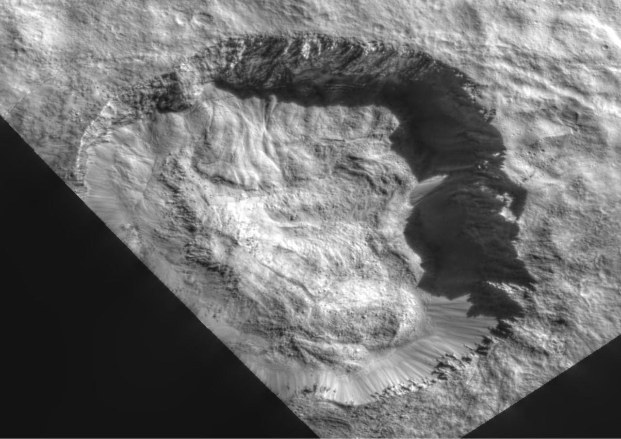
Mojave Crater Floor and Central Uplift
Crater Floor in Arabia Terra Region
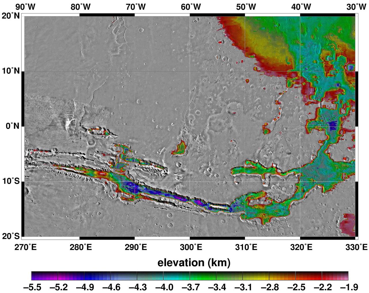
Elevations Within the Floor of the Valles Marineris
Twilight Imaging of Kepler Crater Floor
Ridged Terrain on the Floor Melas Chasma
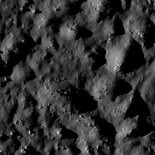
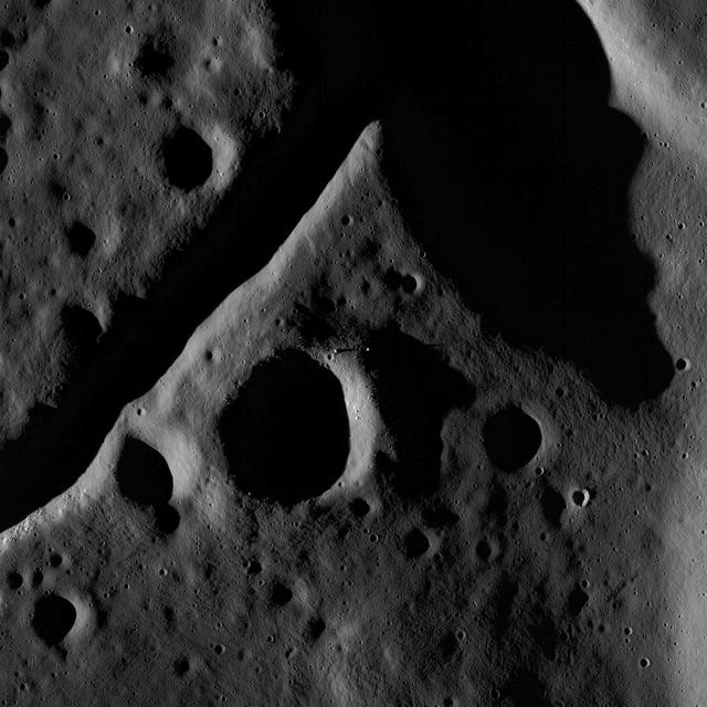
Many fractures on the Moon are seen in the floors of ancient, flat-floored highlands craters in this image taken by NASA Lunar Reconnaissance Orbiter.
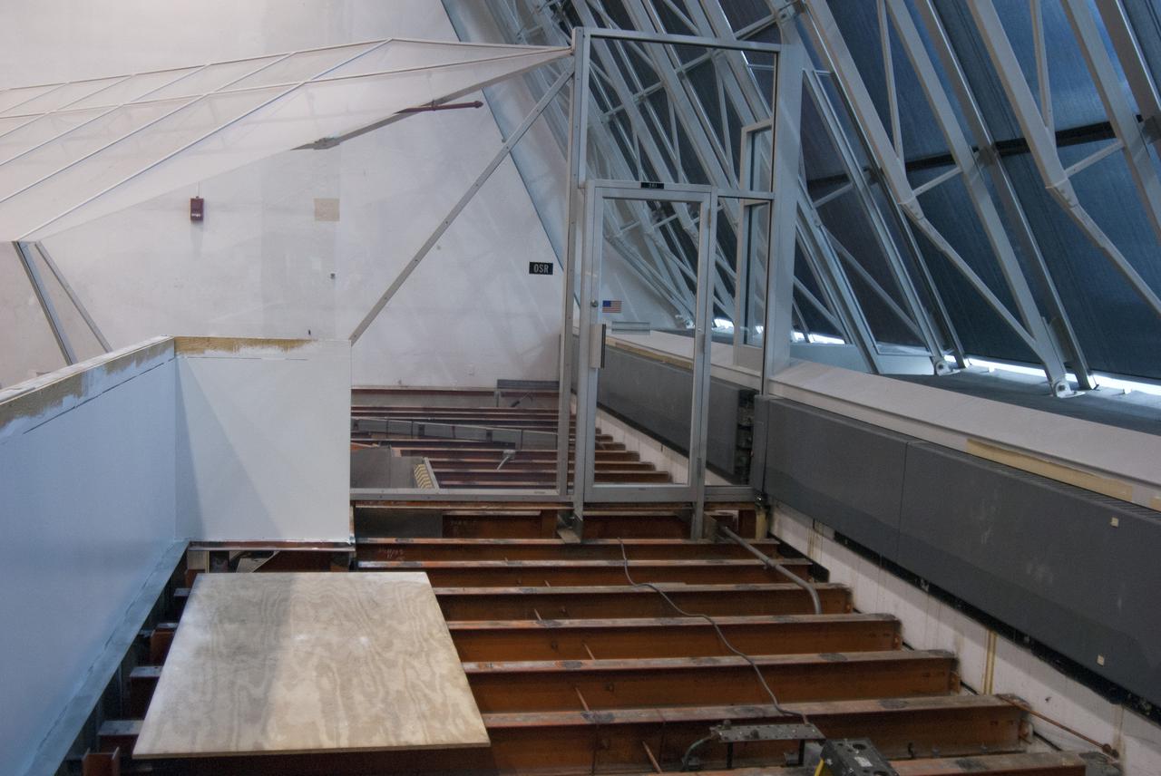
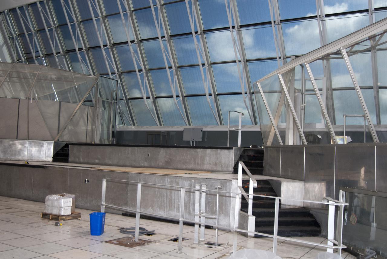
CAPE CANAVERAL, Fla. – At NASA’s Kennedy Space Center in Florida, modifications continue to Firing Room 3 in the Launch Control Center, or LCC. Wiring and conduits below the floor have been upgraded. The legacy flooring leading to and inside a viewing room has been removed and the area is being prepared for new flooring to be installed. Firing Rooms inside the LCC are being upgraded by the Ground System Development and Operations Program at Kennedy to support the processing and launch of multiple types of rockets and spacecraft, whether they are government or commercial models. Kennedy’s Launch Complex 39 is transitioning to support multiple users with the Firing Rooms being modified to be more generic in nature for upcoming programs. Photo credit: NASA_Gary Thompson
Clean room B 29 SSDIF facility floor was installed in January 2019 by Stonhard
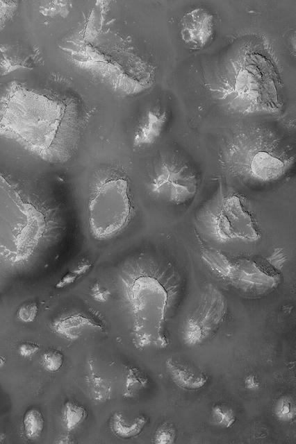
The texture/pattern on the floor of this unnamed crater in Terra Sabaea indicates that volitiles make up a portion of the material filling the crater
This MOC image shows a variety of materials found on the floor of an impact crater northwest of Hellas Planitia
This NASA 2001 Mars Odyssey image shows part of the floor of Coprates Chasma.
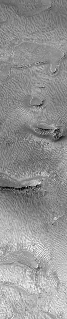
The layered and wind eroded deposits occur on the floor of Chandor Chasma
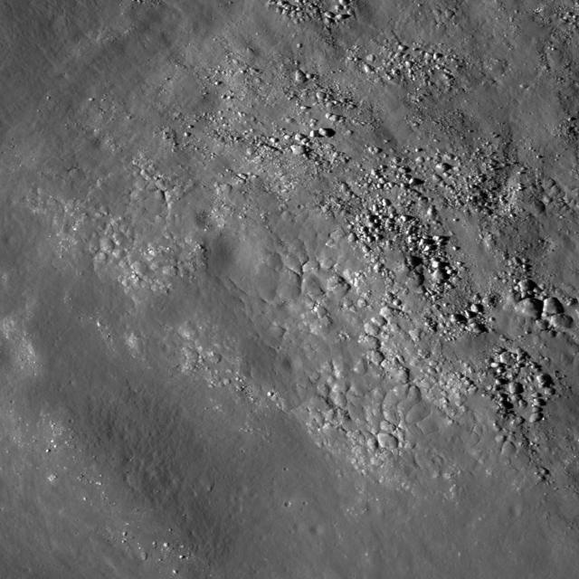
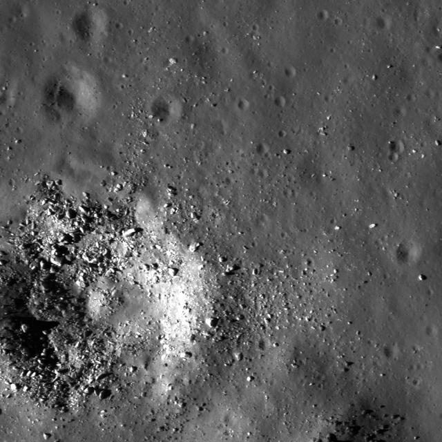
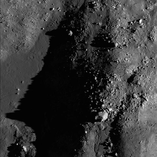
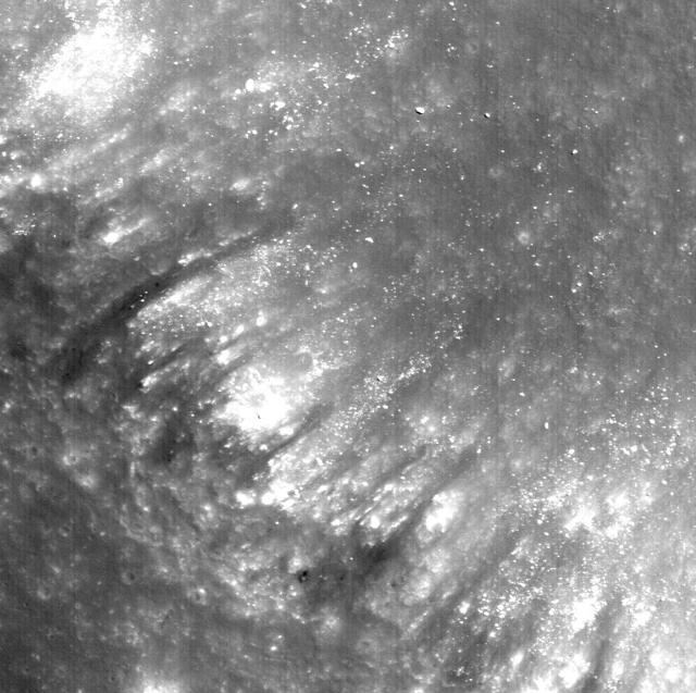
Diverse textures on the floor of Saha E which could be the result of impact melt coating boulders and other deposits on the floor of the crater on the lunar farside in this image taken by NASA Lunar Reconnaissance Orbiter.
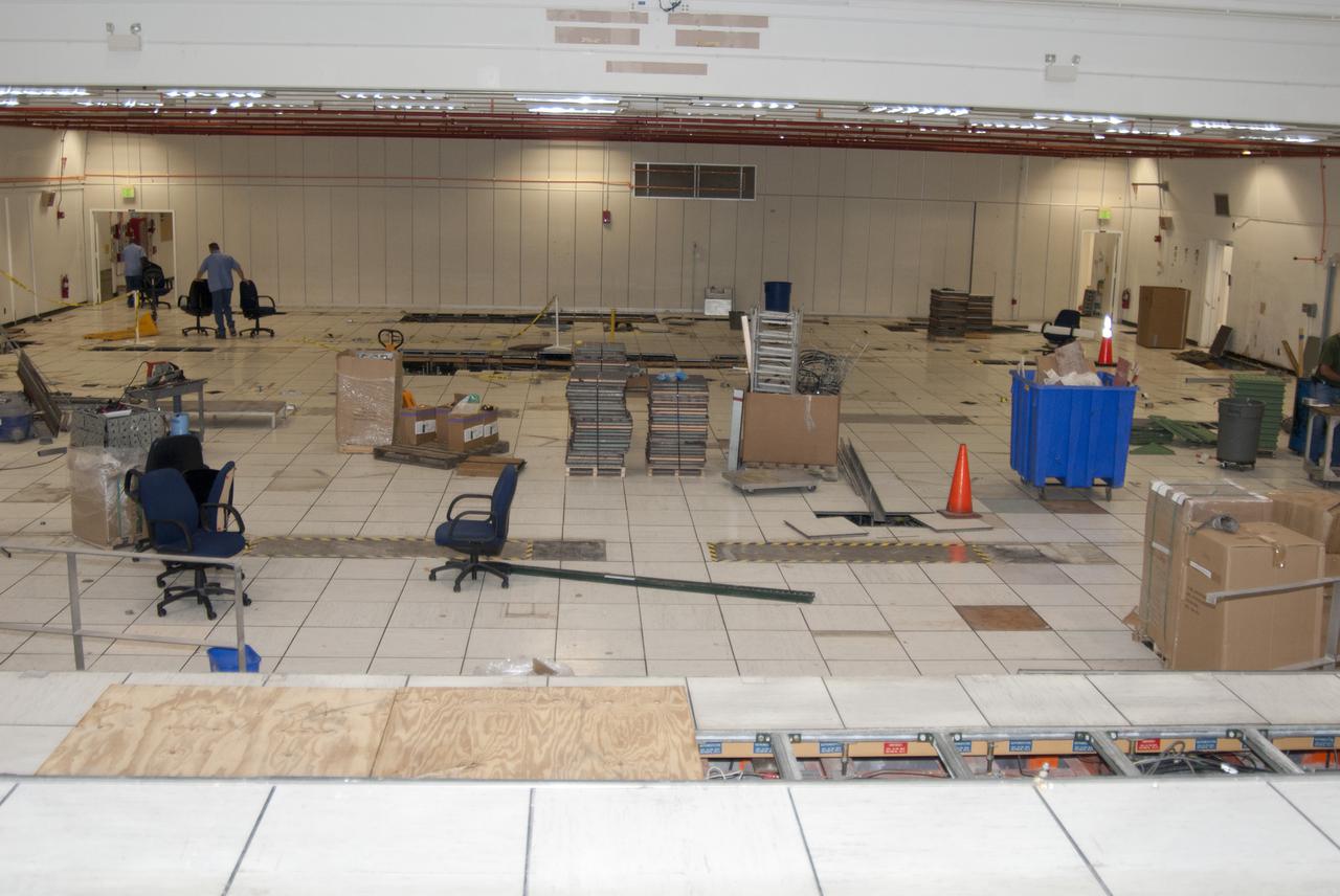
CAPE CANAVERAL, Fla. – At NASA’s Kennedy Space Center in Florida, work continues in Firing Room 2 in the Launch Control Center, or LCC. The legacy flooring is being removed and wiring and conduits below the floor will be upgraded. The mission director’s room to the left and another viewing room to the right also will be upgraded. Firing Rooms inside the LCC are being upgraded by the Ground System Development and Operations Program at Kennedy to support the processing and launch of multiple types of rockets and spacecraft, whether they are government or commercial models. Kennedy’s Launch Complex 39 is transitioning to support multiple users with the Firing Rooms being modified to be more generic in nature for upcoming programs. Photo credit: NASA_Gary Thompson
CAPE CANAVERAL, Fla. – At NASA’s Kennedy Space Center in Florida, work continues in Firing Room 2 in the Launch Control Center, or LCC. The legacy flooring is being removed and wiring and conduits below the floor will be upgraded. Firing Rooms inside the LCC are being upgraded by the Ground System Development and Operations Program at Kennedy to support the processing and launch of multiple types of rockets and spacecraft, whether they are government or commercial models. Kennedy’s Launch Complex 39 is transitioning to support multiple users with the Firing Rooms being modified to be more generic in nature for upcoming programs. Photo credit: NASA_Gary Thompson
CAPE CANAVERAL, Fla. – At NASA’s Kennedy Space Center in Florida, modifications continue to Firing Room 3 in the Launch Control Center, or LCC. Wiring and conduits below the floor have been upgraded and new flooring is being installed. Firing Rooms inside the LCC are being upgraded by the Ground System Development and Operations Program at Kennedy to support the processing and launch of multiple types of rockets and spacecraft, whether they are government or commercial models. Kennedy’s Launch Complex 39 is transitioning to support multiple users with the Firing Rooms being modified to be more generic in nature for upcoming programs. Photo credit: NASA_Gary Thompson
CAPE CANAVERAL, Fla. – At NASA’s Kennedy Space Center in Florida, work continues in Firing Room 2 in the Launch Control Center, or LCC. The legacy flooring is being removed and wiring and conduits below the floor will be upgraded. The mission director’s room to the left and another viewing room to the right also will be upgraded. Firing Rooms inside the LCC are being upgraded by the Ground System Development and Operations Program at Kennedy to support the processing and launch of multiple types of rockets and spacecraft, whether they are government or commercial models. Kennedy’s Launch Complex 39 is transitioning to support multiple users with the Firing Rooms being modified to be more generic in nature for upcoming programs. Photo credit: NASA_Gary Thompson
CAPE CANAVERAL, Fla. – At NASA’s Kennedy Space Center in Florida, modifications continue to Firing Room 3 in the Launch Control Center, or LCC. Wiring and conduits below the floor have been upgraded and new flooring has been installed. Walls have been repaired and are in the process of being painted. Firing Rooms inside the LCC are being upgraded by the Ground System Development and Operations Program at Kennedy to support the processing and launch of multiple types of rockets and spacecraft, whether they are government or commercial models. Kennedy’s Launch Complex 39 is transitioning to support multiple users with the Firing Rooms being modified to be more generic in nature for upcoming programs. Photo credit: NASA_Gary Thompson
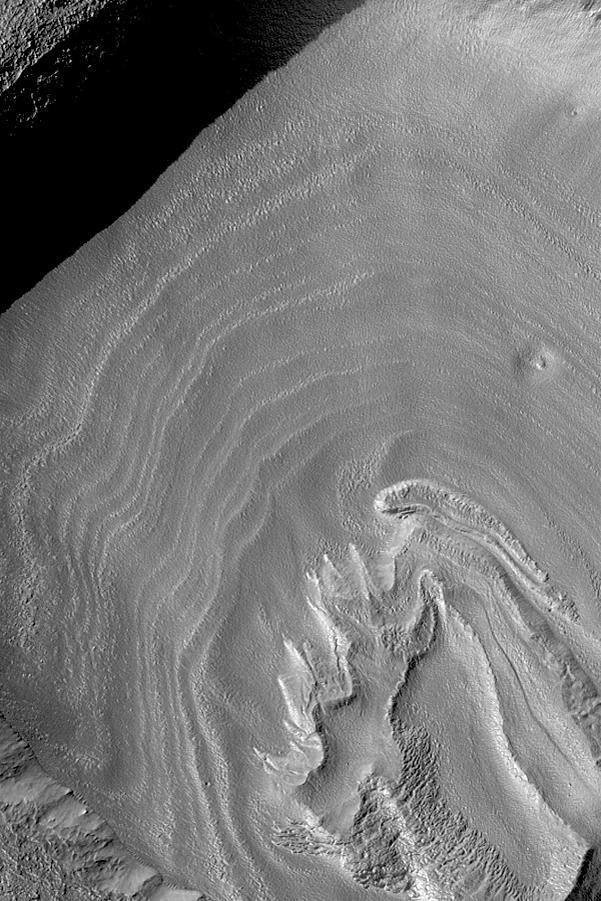
This view from NASA's Dawn mission shows the floor of Ceres' Juling Crater. The crater floor shows evidence of the flow of ice and rock, similar to rock glaciers in Earth's polar regions. Dawn acquired the picture with its framing camera on Aug. 30, 2016. https://photojournal.jpl.nasa.gov/catalog/PIA21920
NASA Lunar Reconnaissance Orbiter shows boulders and impact melt line the floor of the 85-km crater Tycho, a potential site for future human exploration.
Windblown Dunes on the Floor of Herschel Impact Basin
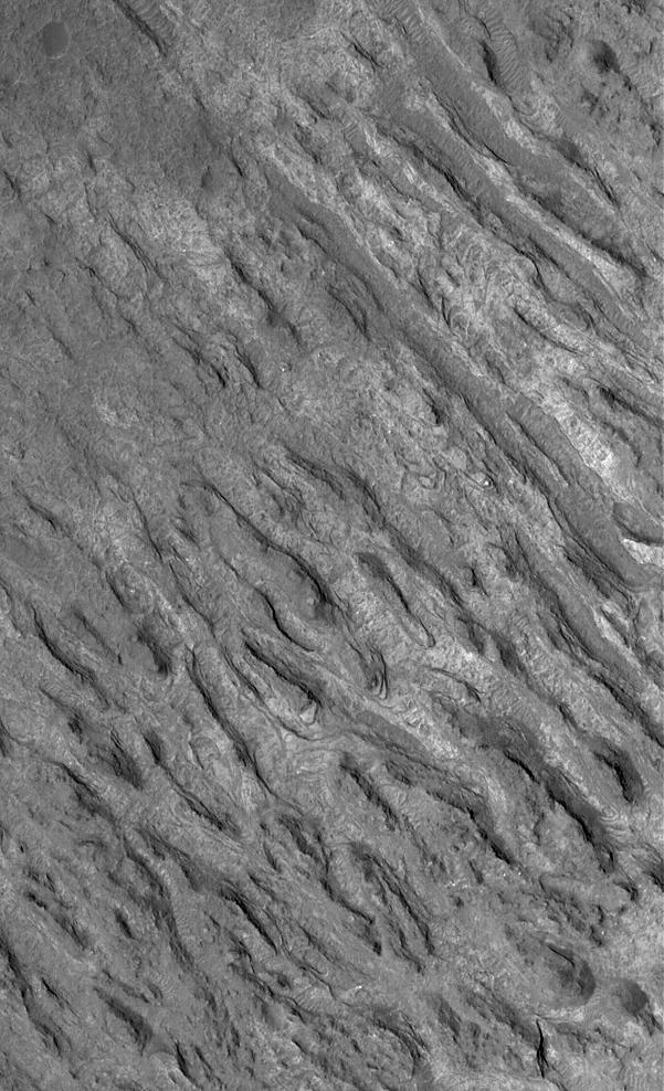
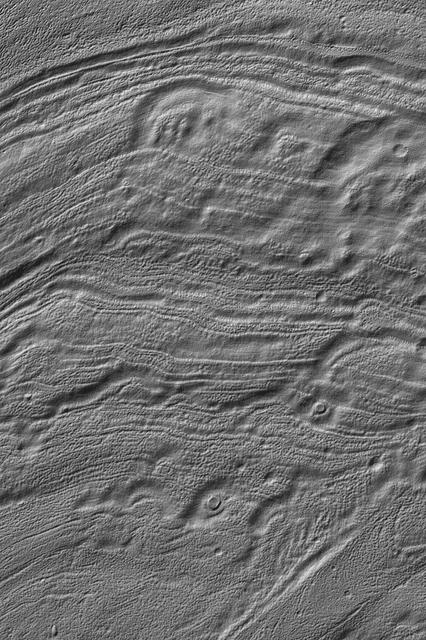
Ridges and Grooves That Wave and Buckle on a Valley Floor
Concentric Crater Floor Deposits in Daedalia Planum
Southern Layered Mound and Floor in Gale Crater
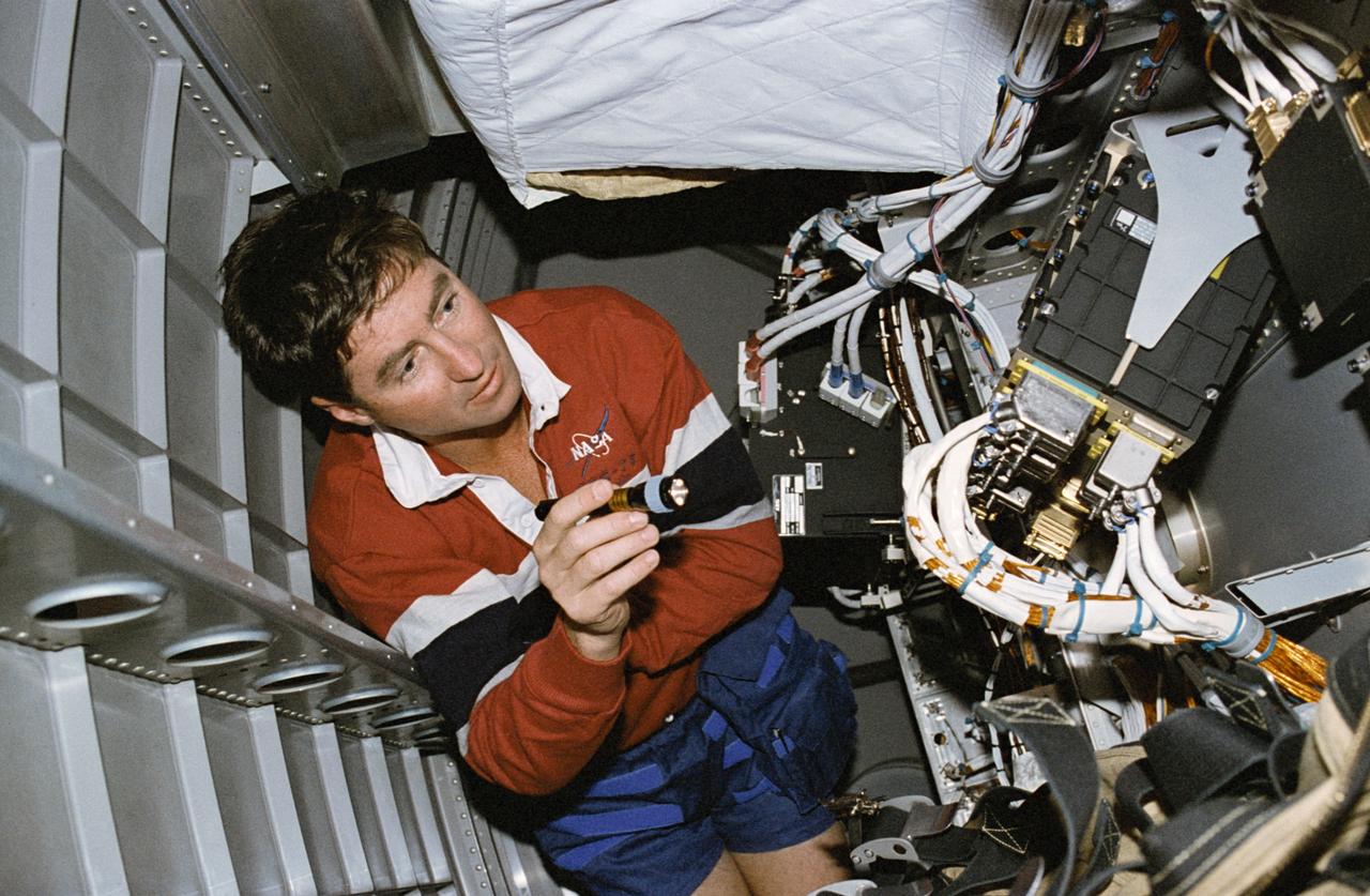
STS078-432-009 (20 June-7 July 1996) --- Among the inflight maintenance (IFM) chores that were handled by the crew members during their almost 17 days in space aboard the space shuttle Columbia was one that involved going into the bay beneath the floor of the Life and Microgravity Spacelab (LMS-1) Science Module. Astronaut Terence T. (Tom) Henricks, mission commander, shines a tiny flashlight onto some cables related to LMS-1 supported computer systems. As in the case of the other IFM chores, Henricks' efforts were successful. He was joined by four other NASA astronauts and two international payload specialists for the space shuttle duration record-setting mission.
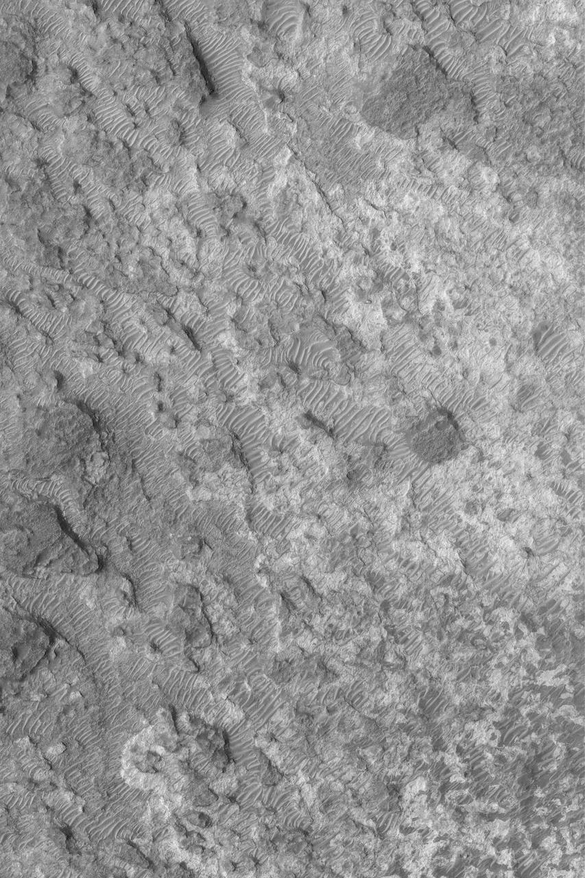
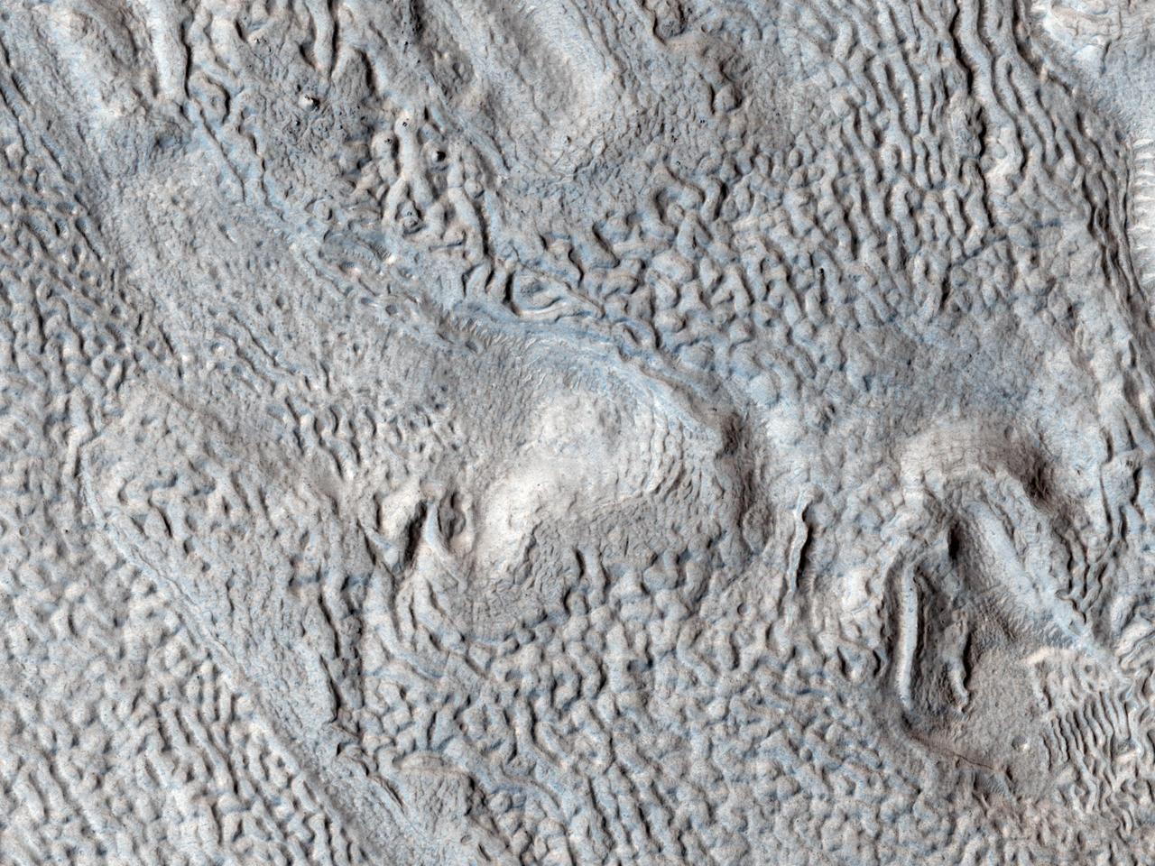
This image from NASA Mars Reconnaissance Orbiter shows a portion of the floor in Palos Crater on equatorial Mars. The floor appears bumpy with high-standing layered knobs; most of its terrain is weathering into meter-size yard-size polygonal blocks.
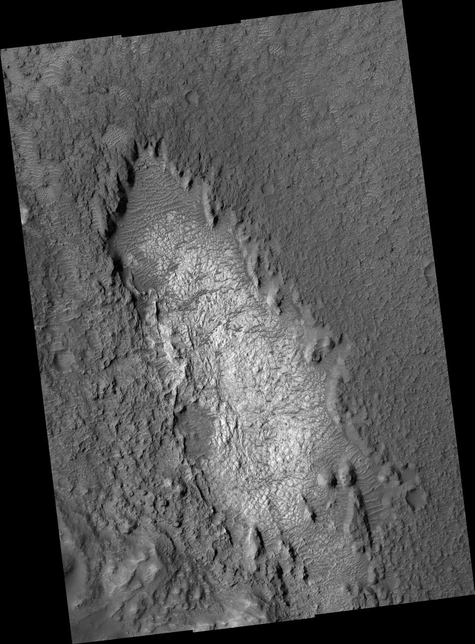
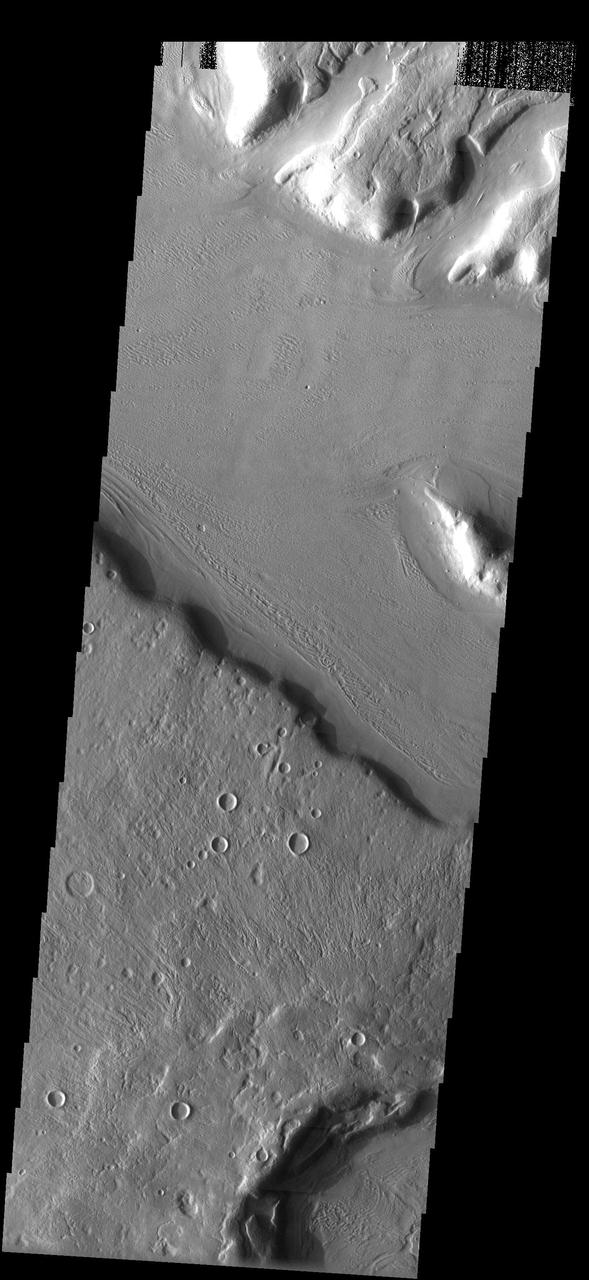
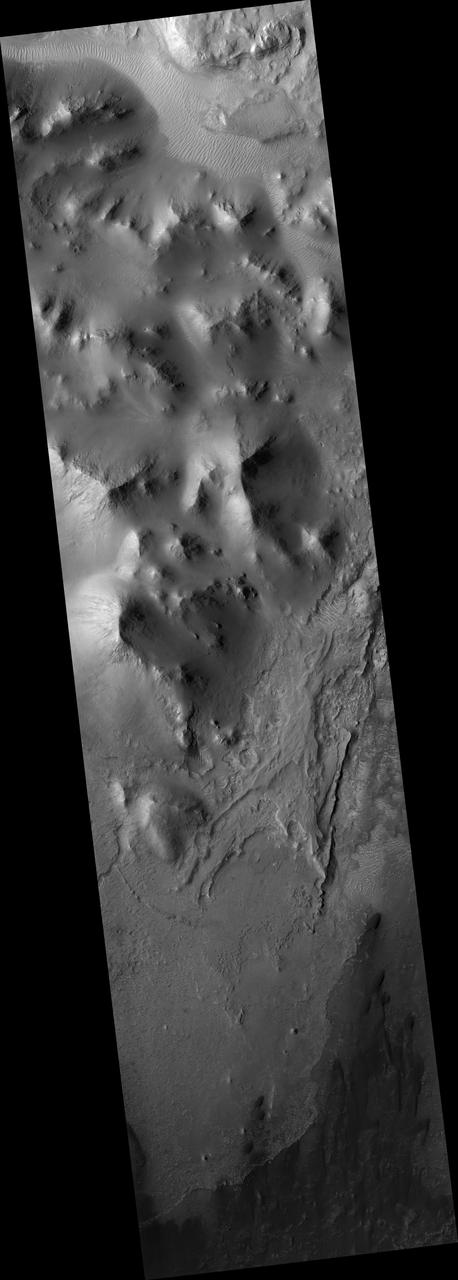
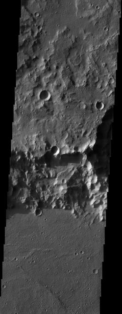
The floor of this crater in Arabia Terra has been filled with material that is now being eroded away
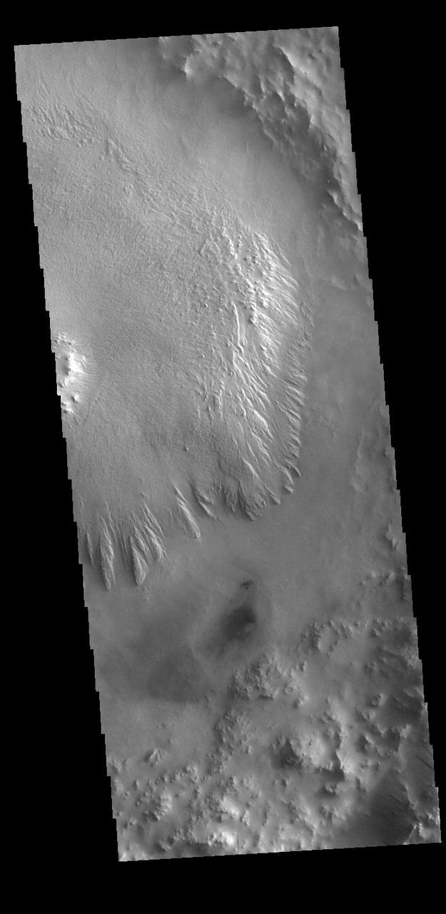
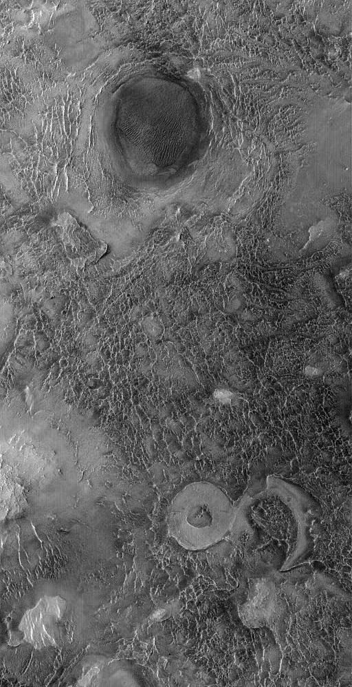
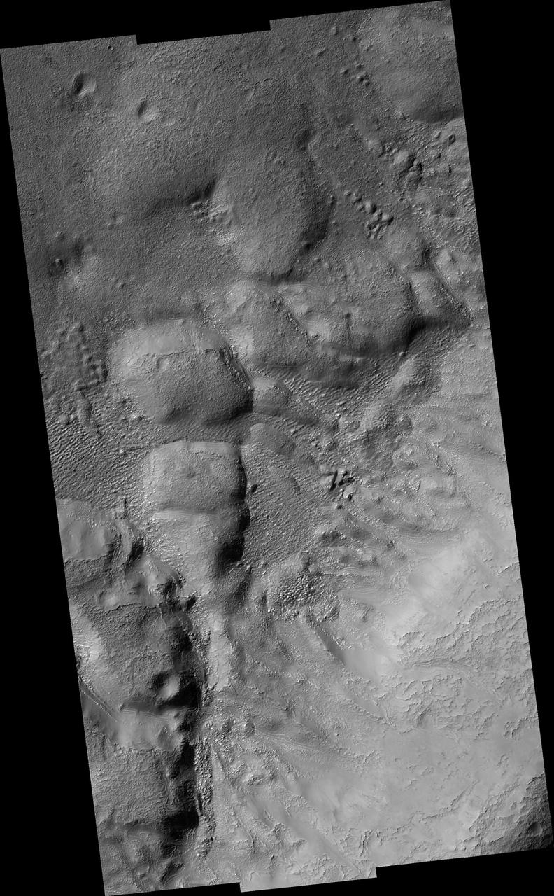
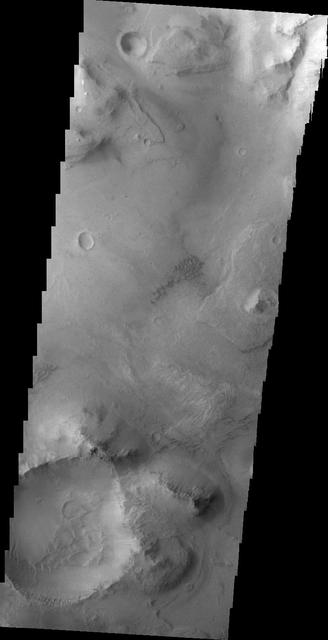
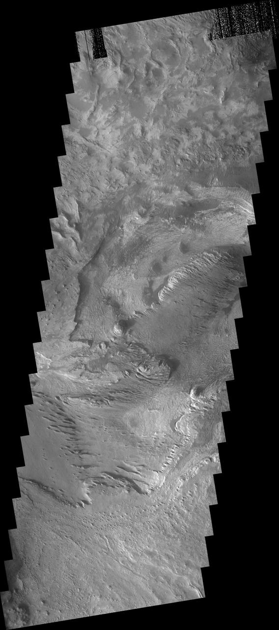
Today's VIS image shows a portion of the floor of an unnamed crater in Arabia Terra. Like several other craters on Mars, including the nearby Henry Crater, this crater contains a large mound of material that filled a large part of the crater floor. This mound has been subsequently eroded by the wind. These materials were brought into the crater sometime after the impact that formed the crater. Orbit Number: 95048 Latitude: 8.48497 Longitude: 21.1439 Instrument: VIS Captured: 2023-05-19 13:22 https://photojournal.jpl.nasa.gov/catalog/PIA26253
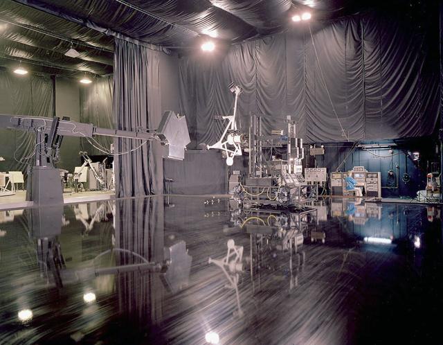
Marshall employees conduct tests on the simulated rendezvous docking mechanism (SRDM)as depicted in this photo of the flat floor area in building 4619.

NASA image release January 14, 2010 LROC WAC image of Tycho crater. Credit: NASA/Goddard/Arizona State University To learn more about this image go to: <a href="http://www.nasa.gov/mission_pages/LRO/multimedia/lroimages/lroc-20100114-tycho.html" rel="nofollow">www.nasa.gov/mission_pages/LRO/multimedia/lroimages/lroc-...</a> <b><a href="http://www.nasa.gov/centers/goddard/home/index.html" rel="nofollow">NASA Goddard Space Flight Center</a></b> contributes to NASA’s mission through four scientific endeavors: Earth Science, Heliophysics, Solar System Exploration, and Astrophysics. Goddard plays a leading role in NASA’s endeavors by providing compelling scientific knowledge to advance the Agency’s mission. <b>Follow us on <a href="http://twitter.com/NASA_GoddardPix" rel="nofollow">Twitter</a></b> <b>Join us on <a href="http://www.facebook.com/pages/Greenbelt-MD/NASA-Goddard/395013845897?ref=tsd" rel="nofollow">Facebook</a></b>

This observation from NASA Mars Reconnaissance Orbiter shows part of the floor of a large impact crater in the southern highlands, north of the giant Hellas impact basin.
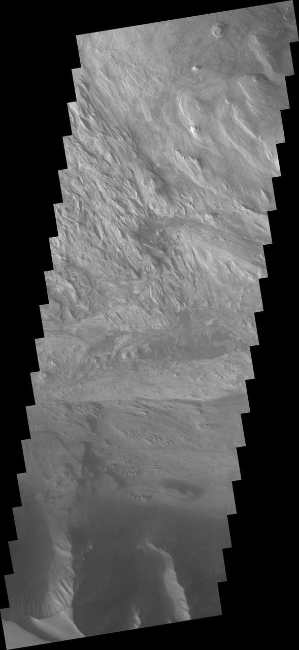
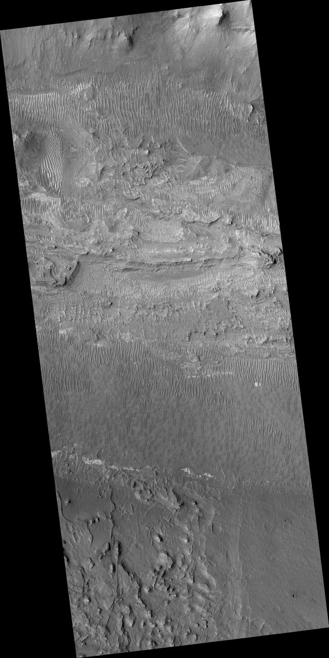
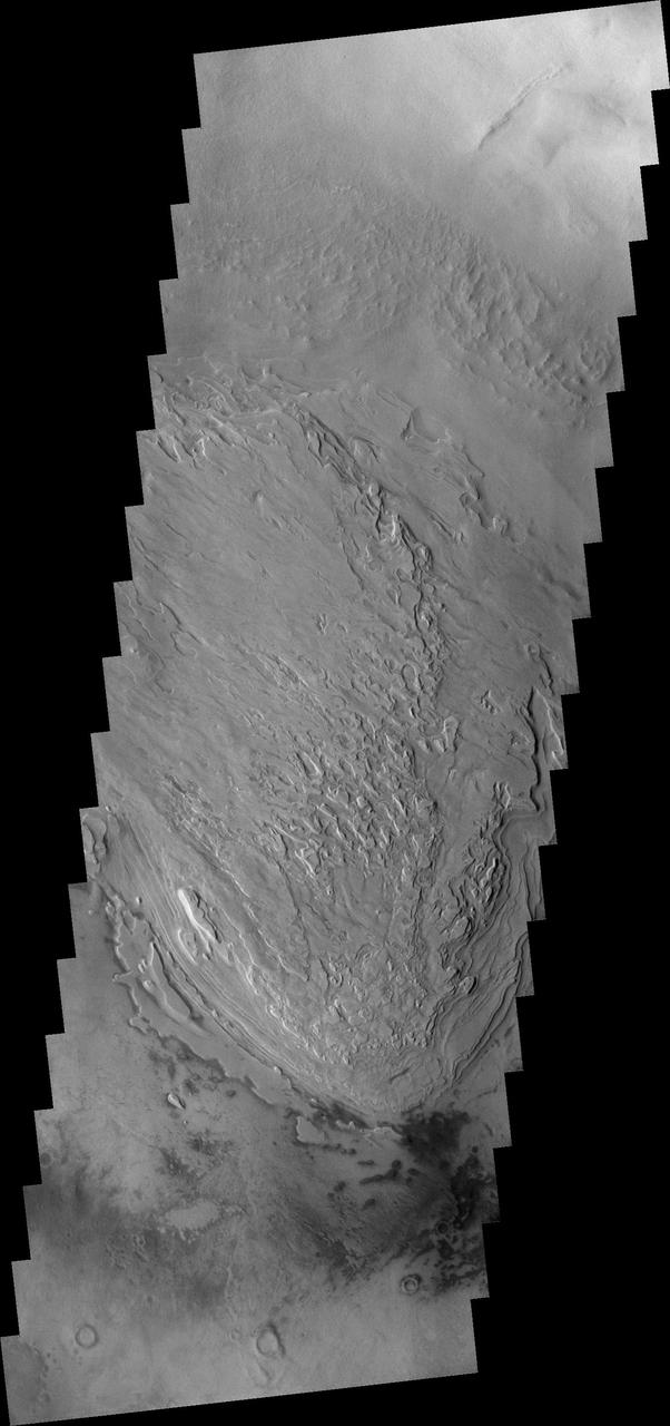
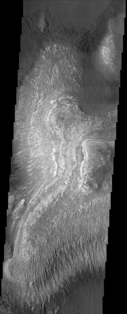
This VIS image from NASA 2001 Mars Odyssey spacecraft shows part of the layered and wind sculpted deposit that occurs on the floor of Candor Chasma.

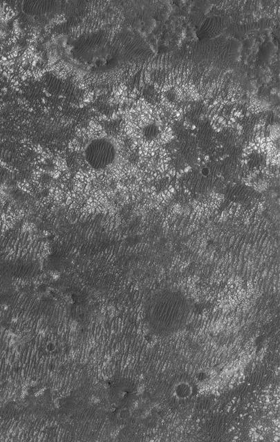
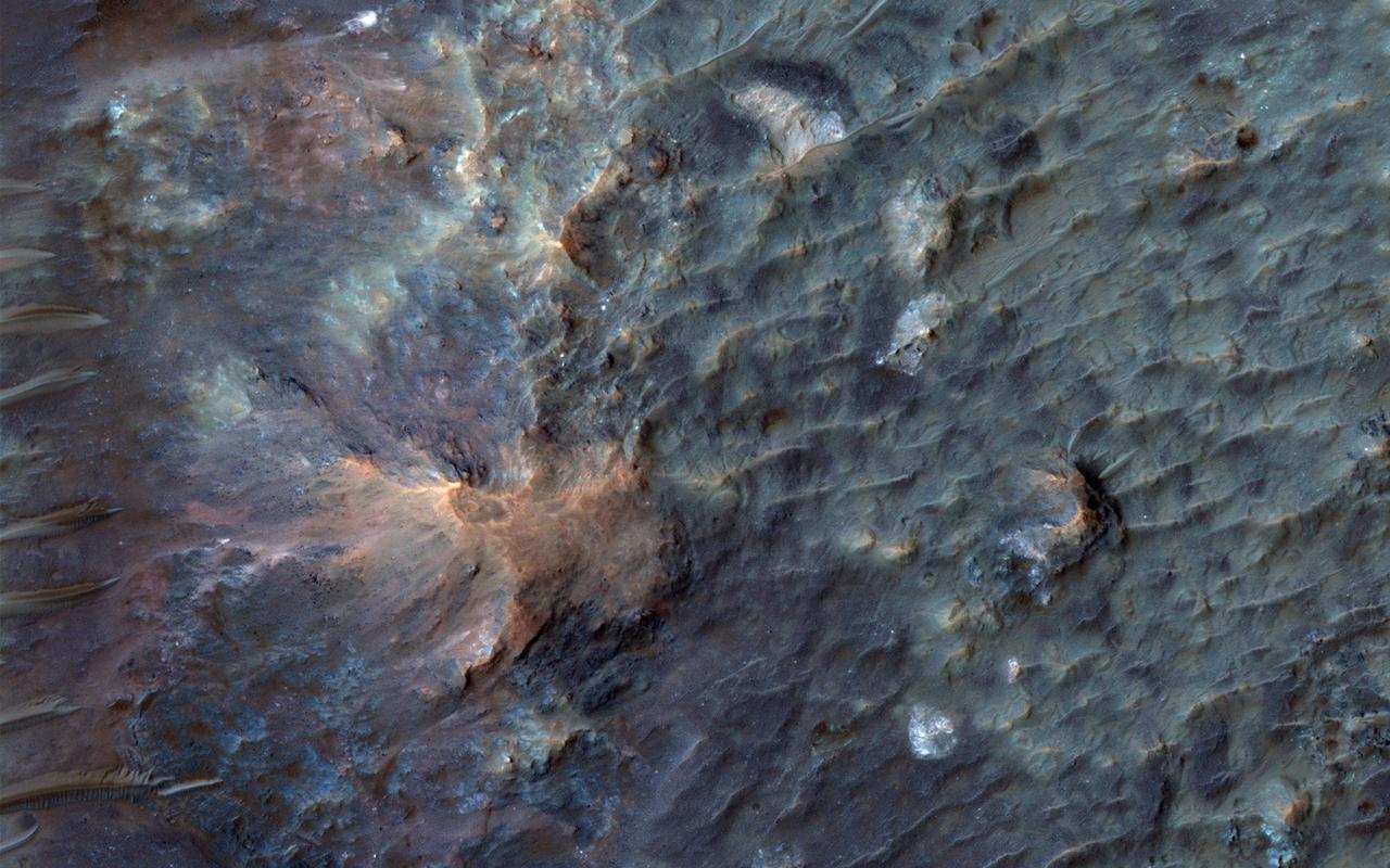
This enhanced color image from NASA's Mars Reconnaissance Orbiter (MRO) shows eroded bedrock on the floor of a large ancient crater. For more information see https://photojournal.jpl.nasa.gov/catalog/PIA22439

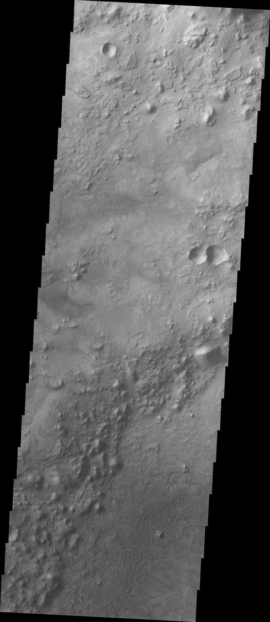
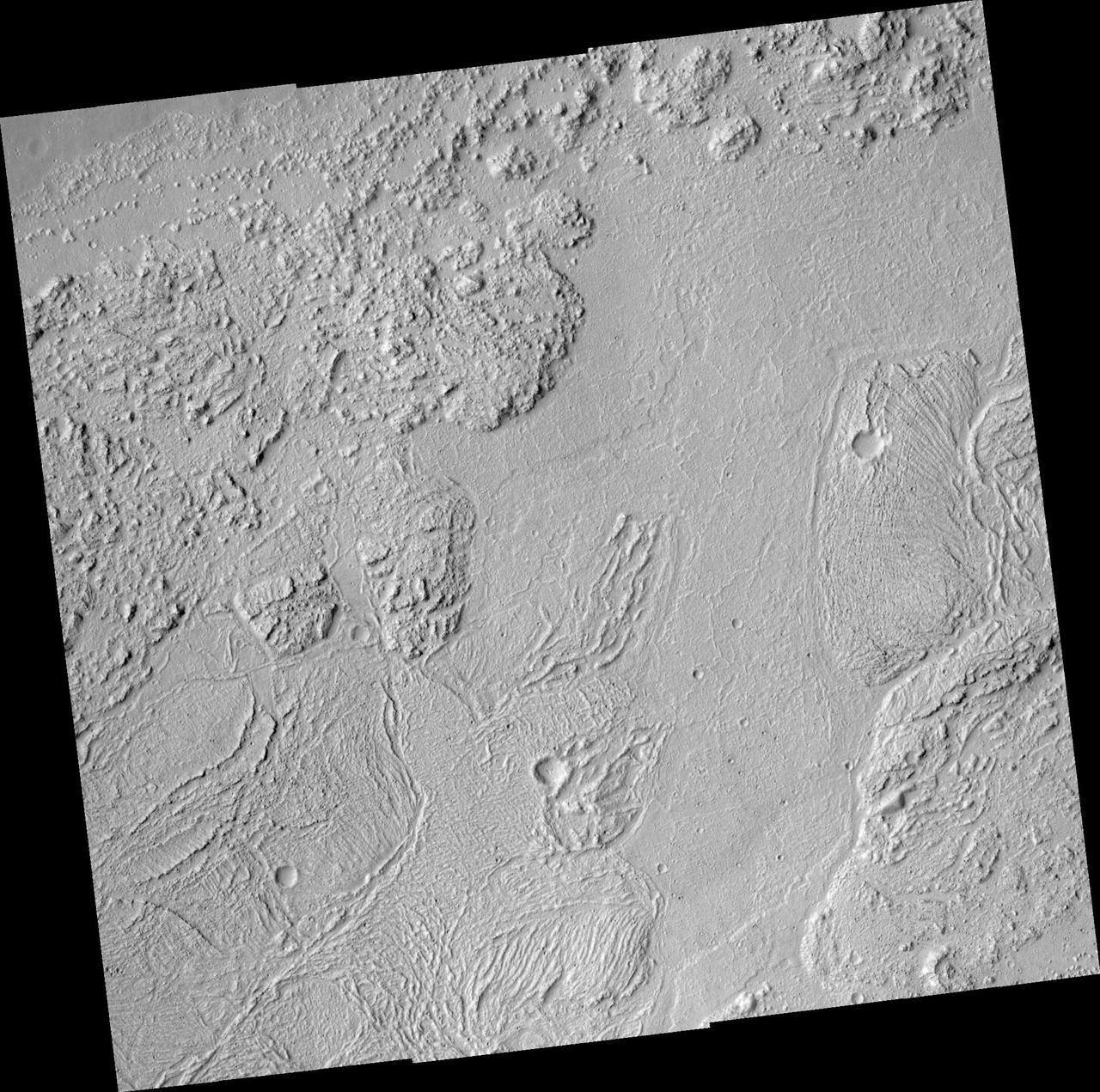
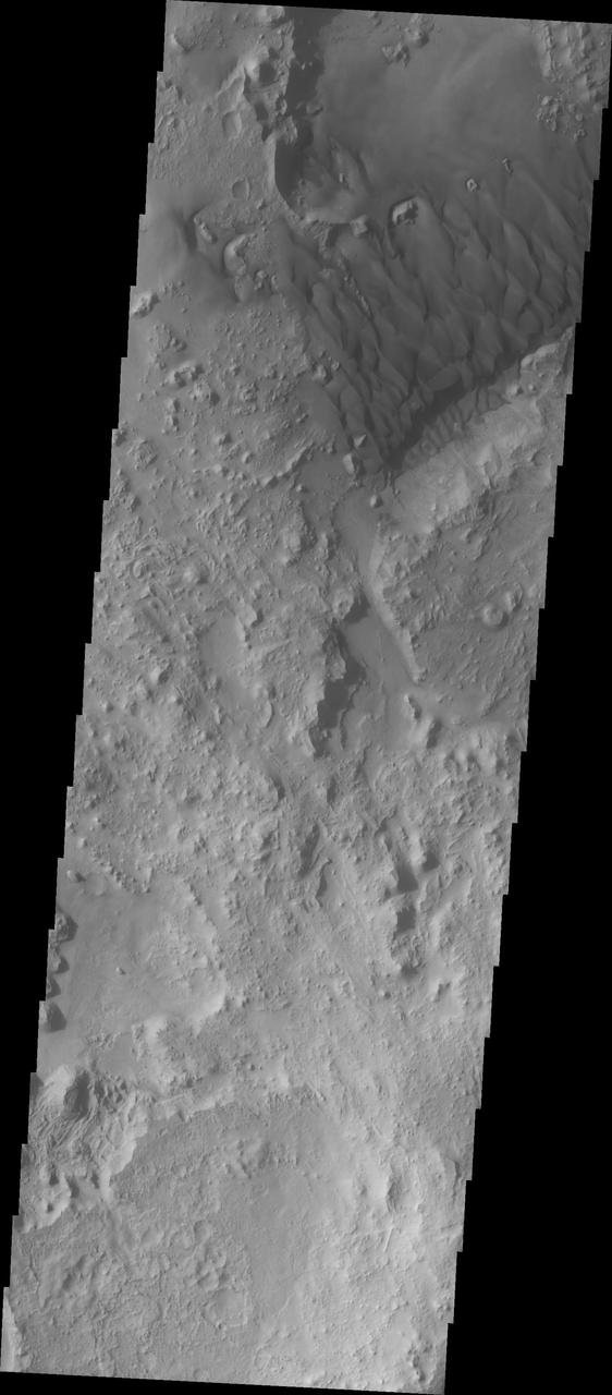
Today's VIS image shows part of an unnamed crater located in Noachis Terra. Unlike most Martian craters, this one has a very rugged floor. Most craters have flat floors, having been filled with materials such as sand blown into the crater, layered deposits from short term lakes, and volcanic materials from nearby flows. The morphology of the crater floor indicates that this is a relatively young crater, with the original floor created during the impact event. Orbit Number: 93133 Latitude: -41.7607 Longitude: 16.3316 Instrument: VIS Captured: 2022-12-12 20:18 https://photojournal.jpl.nasa.gov/catalog/PIA25841
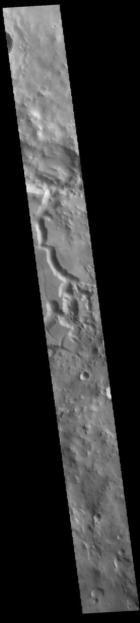
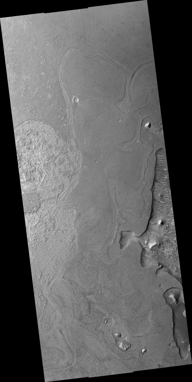
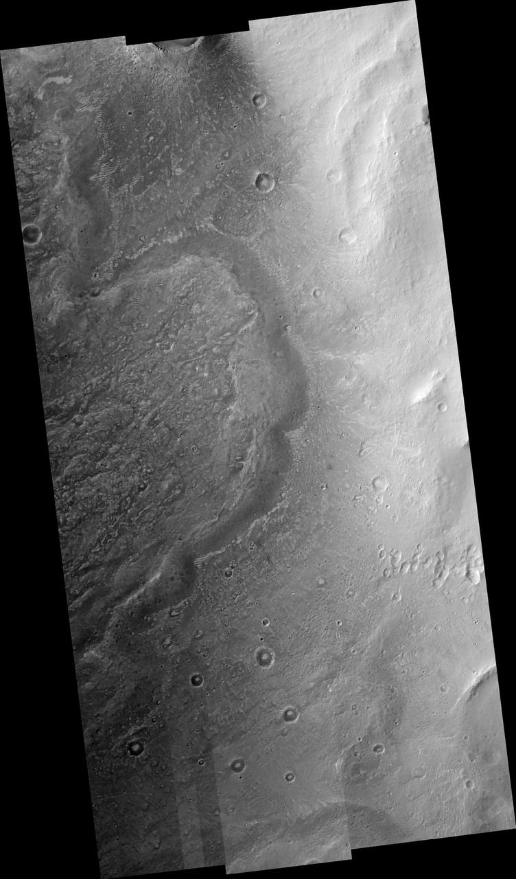
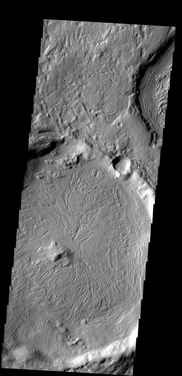
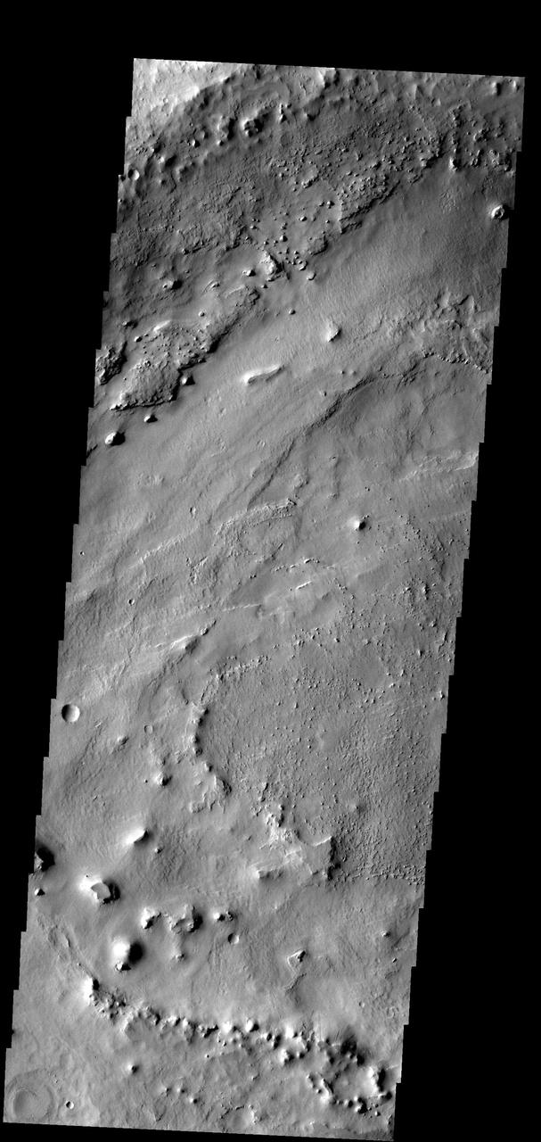
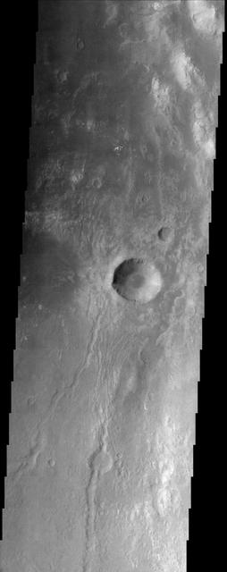
This VIS image crosses an unnamed crater in Terra Sabaea. The entire crater floor is covered by materials of unknown origin. Those materials are be eroded and appear to be forming chaos. The channel feature may be related to fluid activity, where the underlying material is losing water and the surface is collapsing – rather than the flow of a river over the surface. Orbit Number: 88009 Latitude: 2.76492 Longitude: 53.6692 Instrument: VIS Captured: 2021-10-16 23:10 https://photojournal.jpl.nasa.gov/catalog/PIA25109
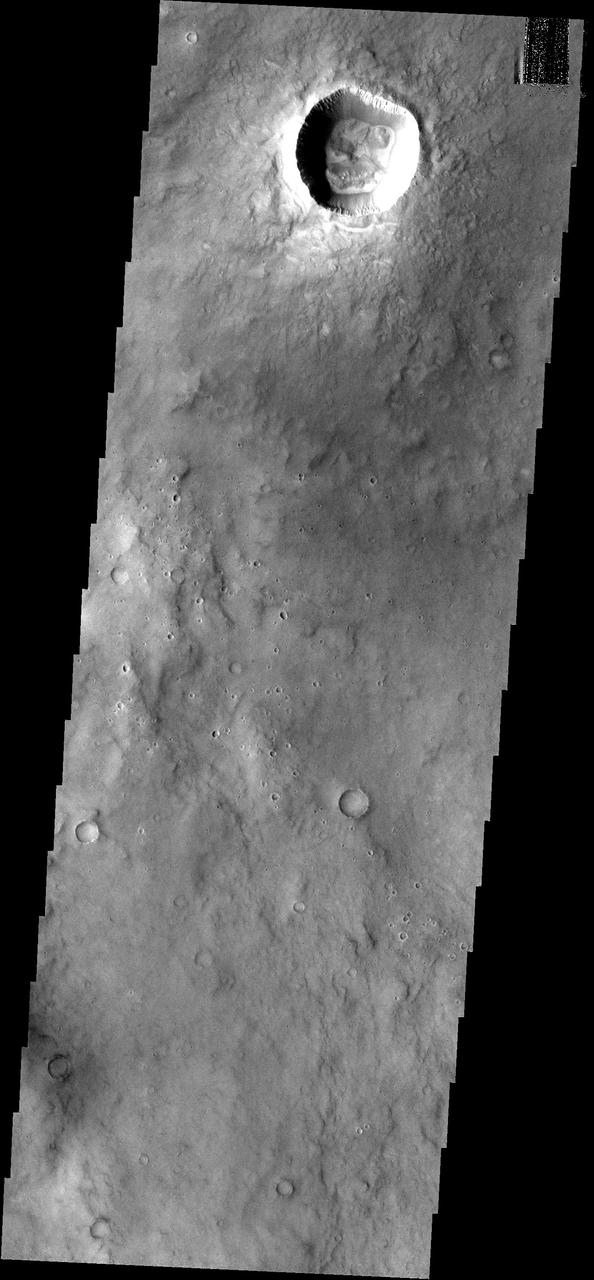
The impact crater observed in this NASA Mars Odyssey image taken in Terra Cimmeria suggests sediments have filled the crater due to the flat and smooth nature of the floor compared to rougher surfaces at higher elevations.
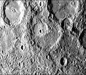
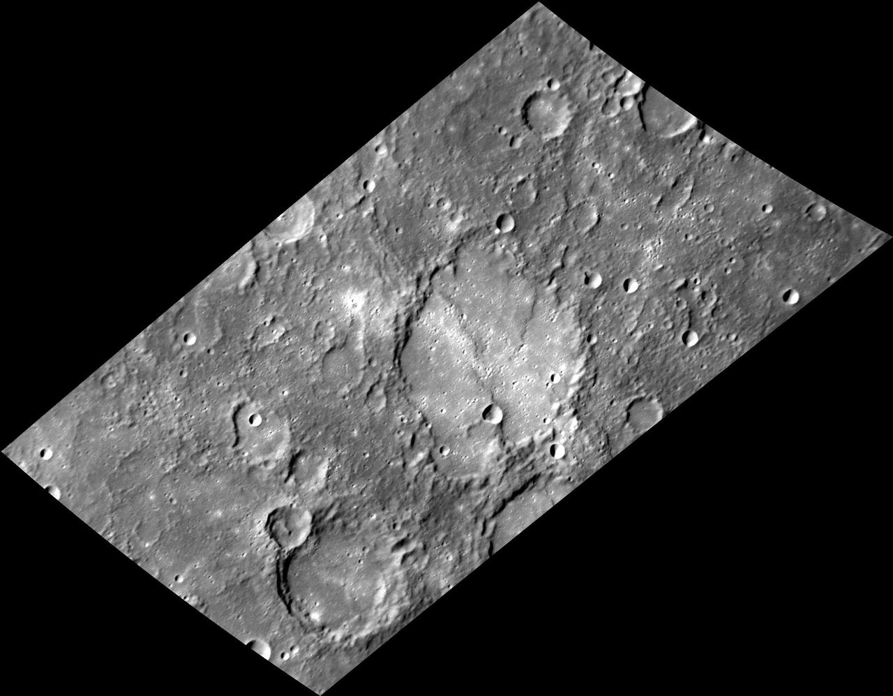
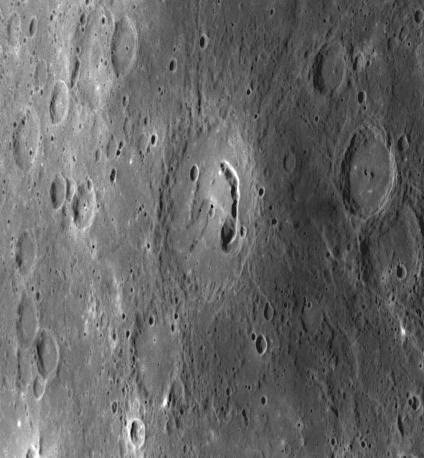
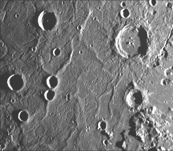
This image, from NASA Mariner 10 spacecraft which launched in 1974, shows several scarps, which appear to be confined to crater floors. The scarp in the crater at the upper left of the image has been diverted by the central peaks.
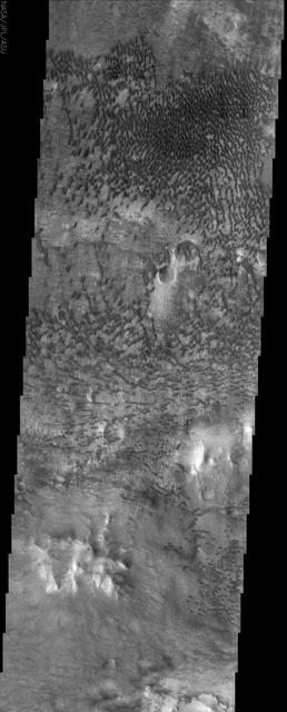
This NASA Mars Odyssey image shows a remarkable array of dunes on the floor of a large impact crater named Baldet. Many of the dunes in this region are isolated features with large, sand-free interdune surfaces between the individual dunes.
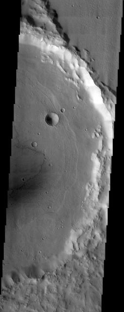
The eastern floor of Holden Crater, which is located in region of the southern hemisphere called Noachis Terra and is 154 km in diameter, is seen in this image from NASA Mars Odyssey spacecraft.
West of NASA Curiosity landing site, this image from NASA Mars Reconnaissance Orbiter spacecraft along the northwestern floor of Gale Crater is between Aeolis Mons informally called Mt. Sharp and the crater rim.
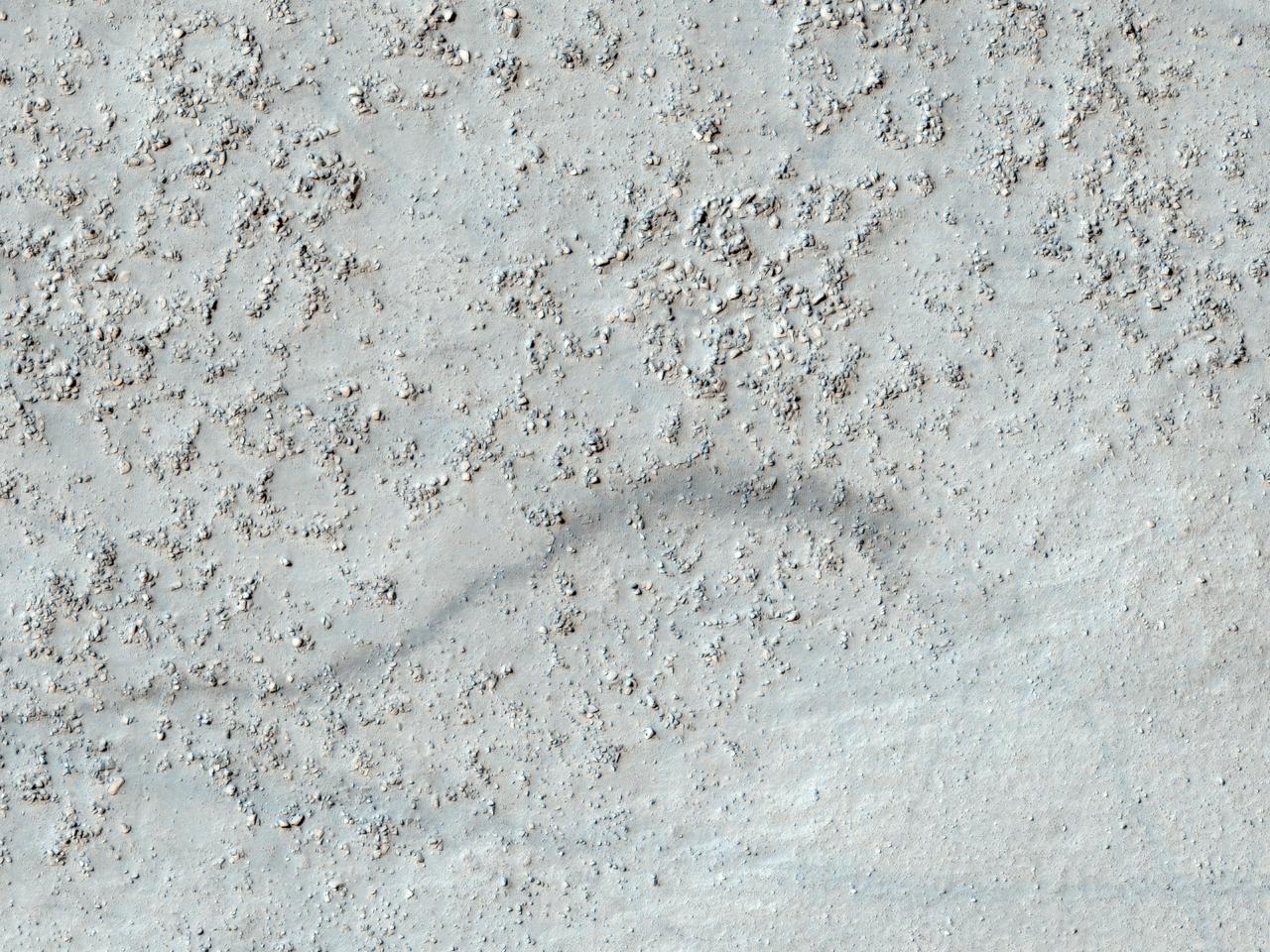
This image from NASA Mars Reconnaissance Rover shows a degraded impact crater in the southern highlands. Part of the crater rim is visible at the top and bottom of the image, with the boulder-covered crater floor in the center.
Taken by one of the Mars Student Imaging Project MSIP teams, these are the unusual floor deposits in Spallanzani Crater. The wind may have affected the surface of the layered deposit. Small dunes have formed near the southern margin
The central peak and fractured floor of Compton crater as imaged by the LROC Narrow Angle Camera onboard NASA Lunar Reconnaissance Orbiter at dusk, image width is ~1720 meters.
This crater on Mars, observed by NASA Mars Reconnaissance Orbiter, was named after Dr. Gerald A. Soffen February 7, 1926 - November 22, 2000, and this image covers a small portion of the crater floor. http://photojournal.jpl.nasa.gov/catalog/PIA14453
These layered deposits are located on the floor of a large canyon called Ganges Chasma which is a part of the Valles Marineris in this image captured by NASA 2001 Mars Odyssey spacecraft.
This image, from NASA Mariner 10 spacecraft which launched in 1974, includes part of the floor of the Caloris basin showing the ridges and fractures.
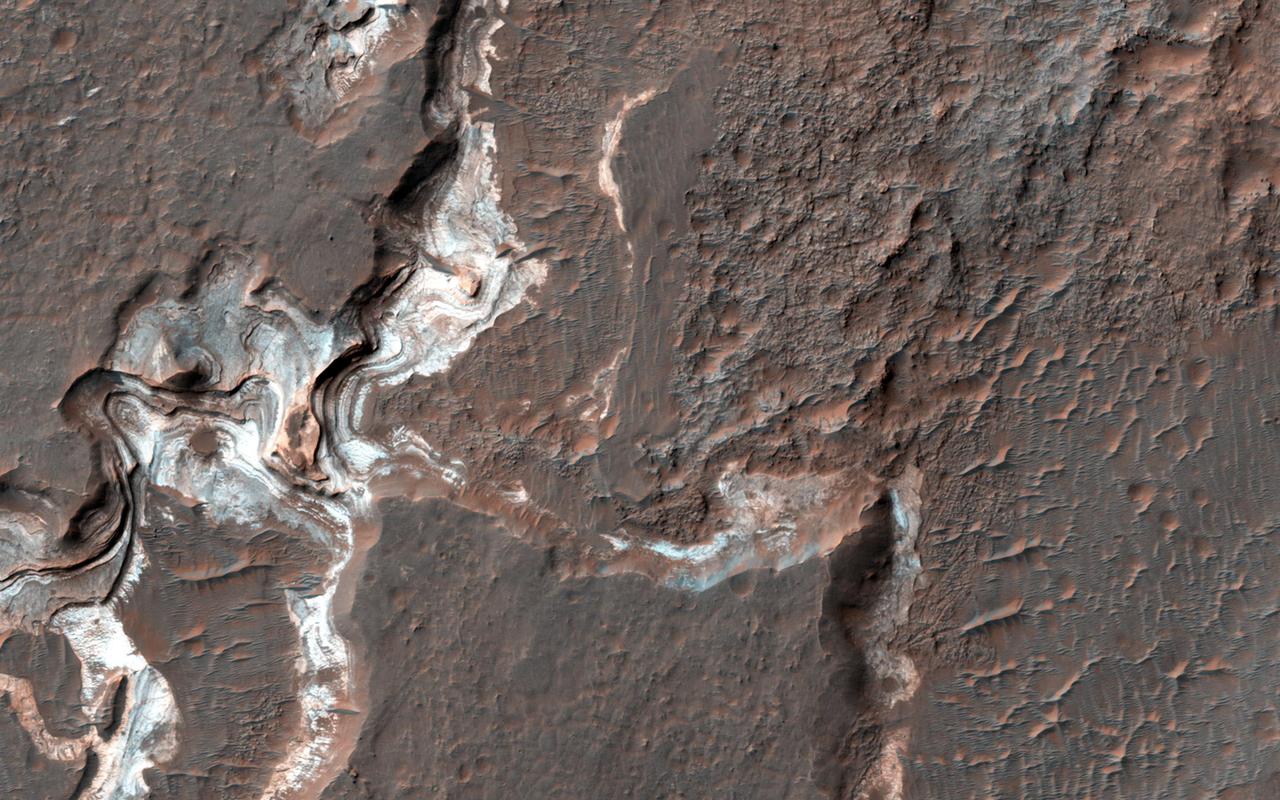
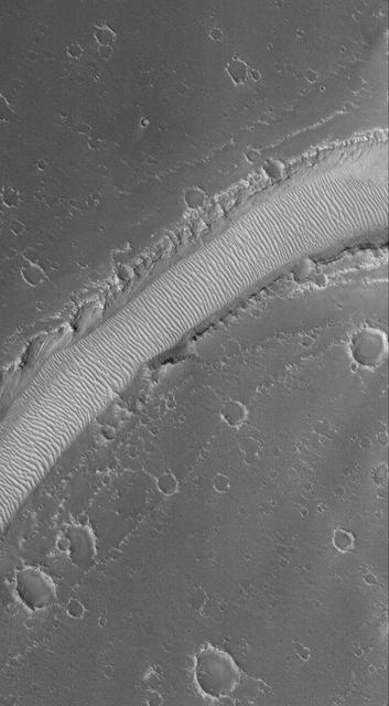
This image shows some bright layered deposits exposed within a linear trough along the floor of the Ladon Basin as seen by NASA Mars Reconnaissance Orbiter.
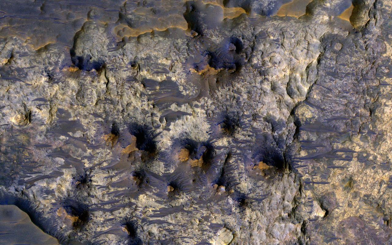
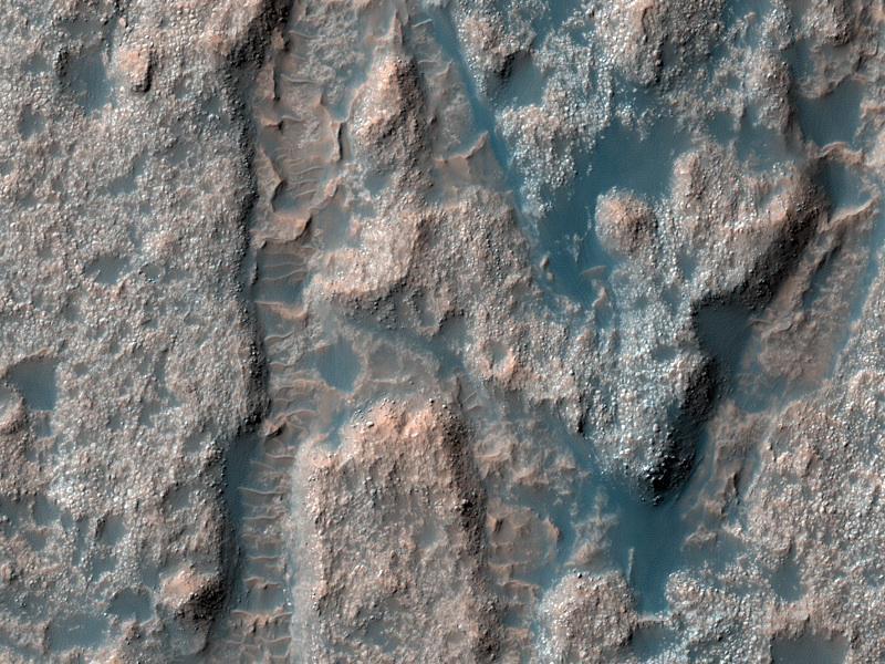
This image shows the floor of Suzhi Crater, an approximately 25-kilometer diameter impact crater located northeast of Hellas Planitia. The crater floor is mostly covered by dark-toned deposits; however some patches of the underlying light-toned bedrock are now exposed, like in this Context Camera image. This enhanced-color infrared image shows a close up of the exposed bedrock on the floor of the crater. Here we can see the lighter-toned bedrock partially covered up by darker-toned bedrock and a few wind-blown bedforms. The lighter-toned bedrock appears to lie over yet another type of bedrock in our image, which appears to be yellowish and heavily fractured. What complex tale of Martian geologic and climate history might these rocks tell us if we were able to sample them in person? Perhaps, one day we'll know. The University of Arizona, Tucson, operates HiRISE, which was http://photojournal.jpl.nasa.gov/catalog/PIA21273
Elysium Mons Volcano - Detail of Southern Caldera Wall and Floor