The Aerostructures Test Wing (ATW), which consisted of an 18-inch carbon fiber test wing with surface-mounted piezoelectric strain actuators, was mounted on a special ventral flight test fixture and flown on Dryden's F-15B Research Testbed aircraft
The Aerostructures Test Wing (ATW) experiment, which consisted of an 18-inch carbon fiber test wing with surface-mounted piezoelectric strain actuators, undergoing ground testing prior to flight on Dryden's F-15B Research Testbed aircraft
The Aerostructures Test Wing (ATW), which consisted of an 18-inch carbon fiber test wing with surface-mounted piezoelectric strain actuators, following intentional failure on its final flight
This photo shows the Shuttle tile flight test fixture under the wing of a National Oceanographic and Atmospheric Administration WP-3D aircraft.
Shuttle Tile Flight Test Fixture (FTF) on NOAA WP-3D Orion aircraft
A close up of the Flight Test Fixture II, mounted on the underside of the F-15B Aerodynamic Flight Facility aircraft. The Thermal Protection System (TPS) samples, which included metallic Inconel tiles, soft Advanced Flexible Reusable Surface Insulation tiles, and sealing materials, were attached to the forward-left side position of the test fixture. In-flight video from the aircraft's on-board video system, as well as chase aircraft photos and video footage, documented the condition of the TPS during flights. Surface pressures over the TPS was measured by thermocouples contained in instrumentation "islands," to document shear and shock loads.
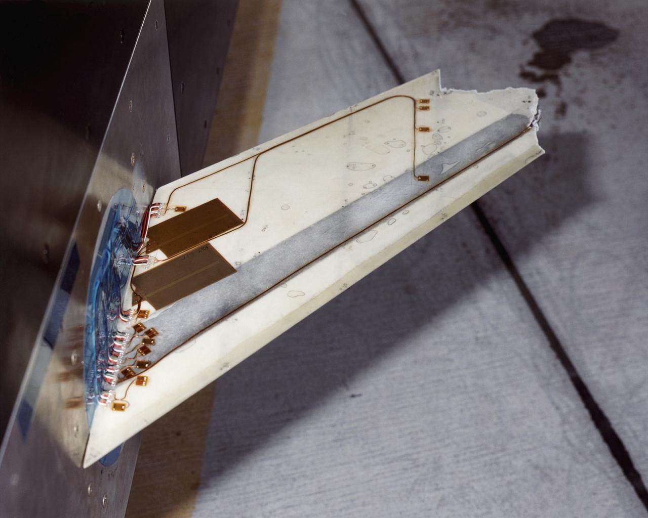
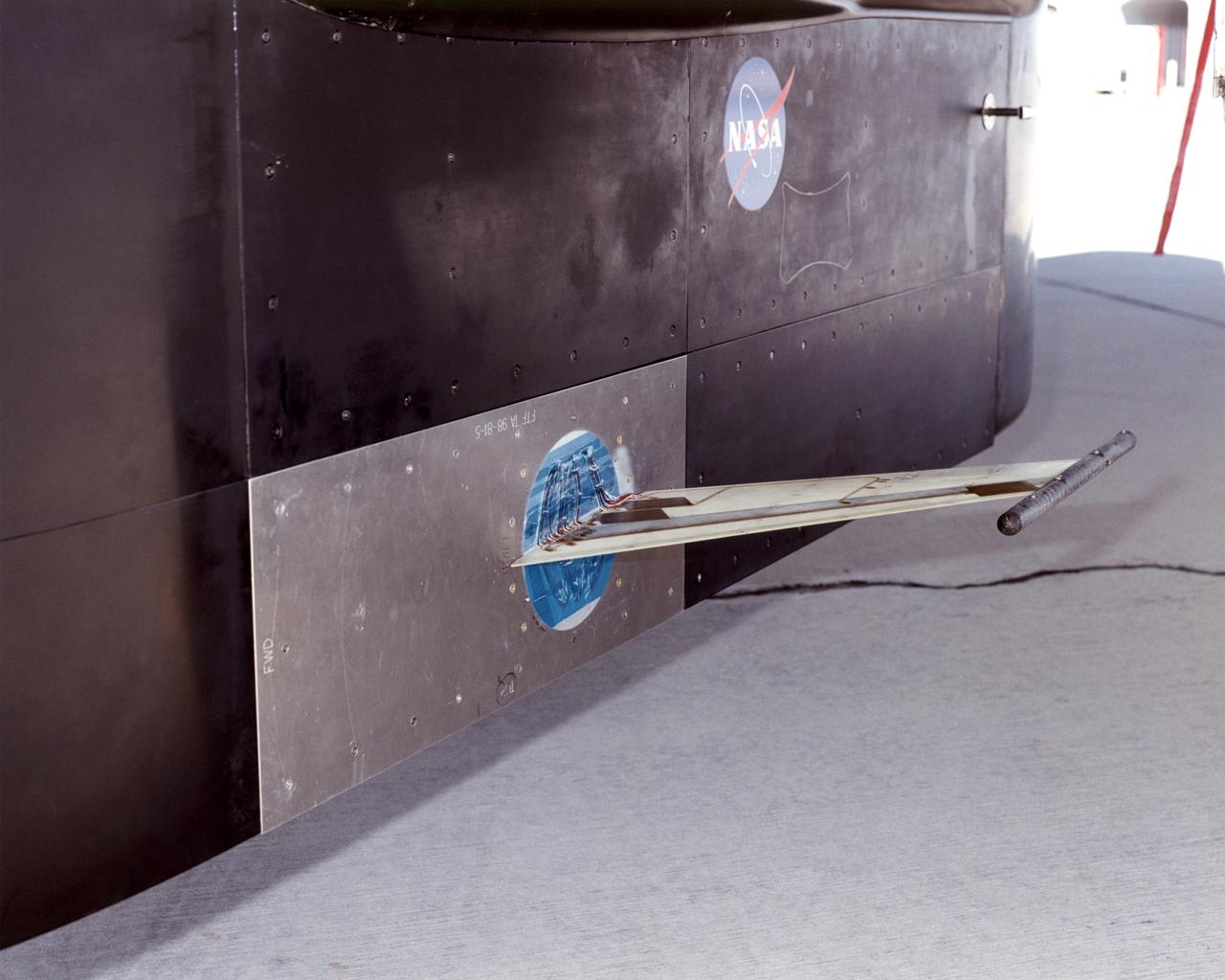
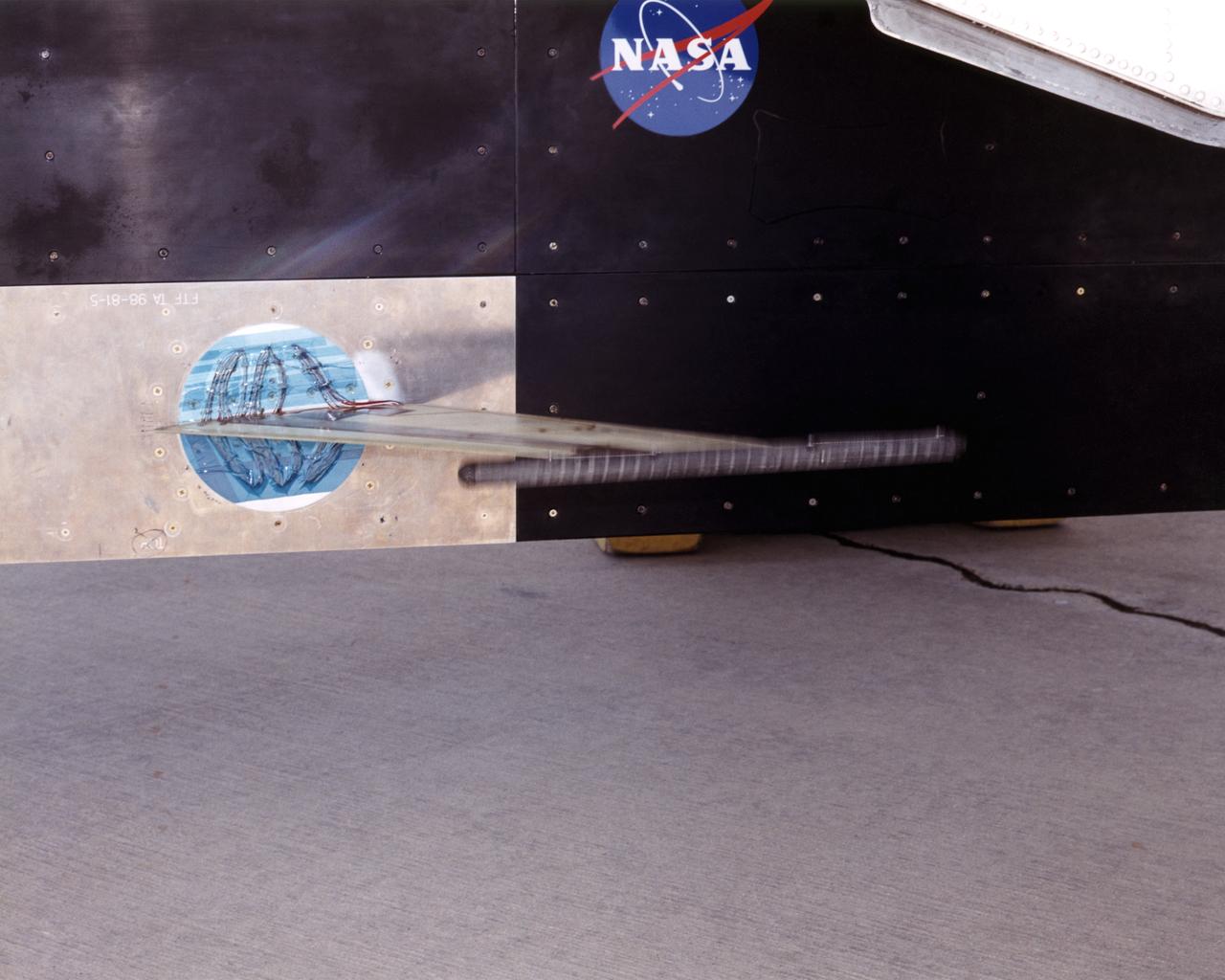
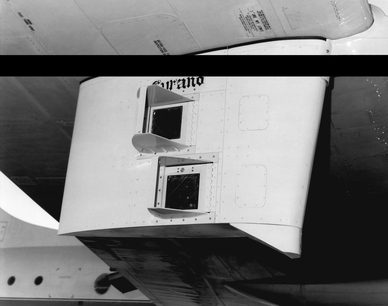
Closeup of F-15B Flight Test Fixture (FTF) with X-33 Thermal Protection Systems (TPS)