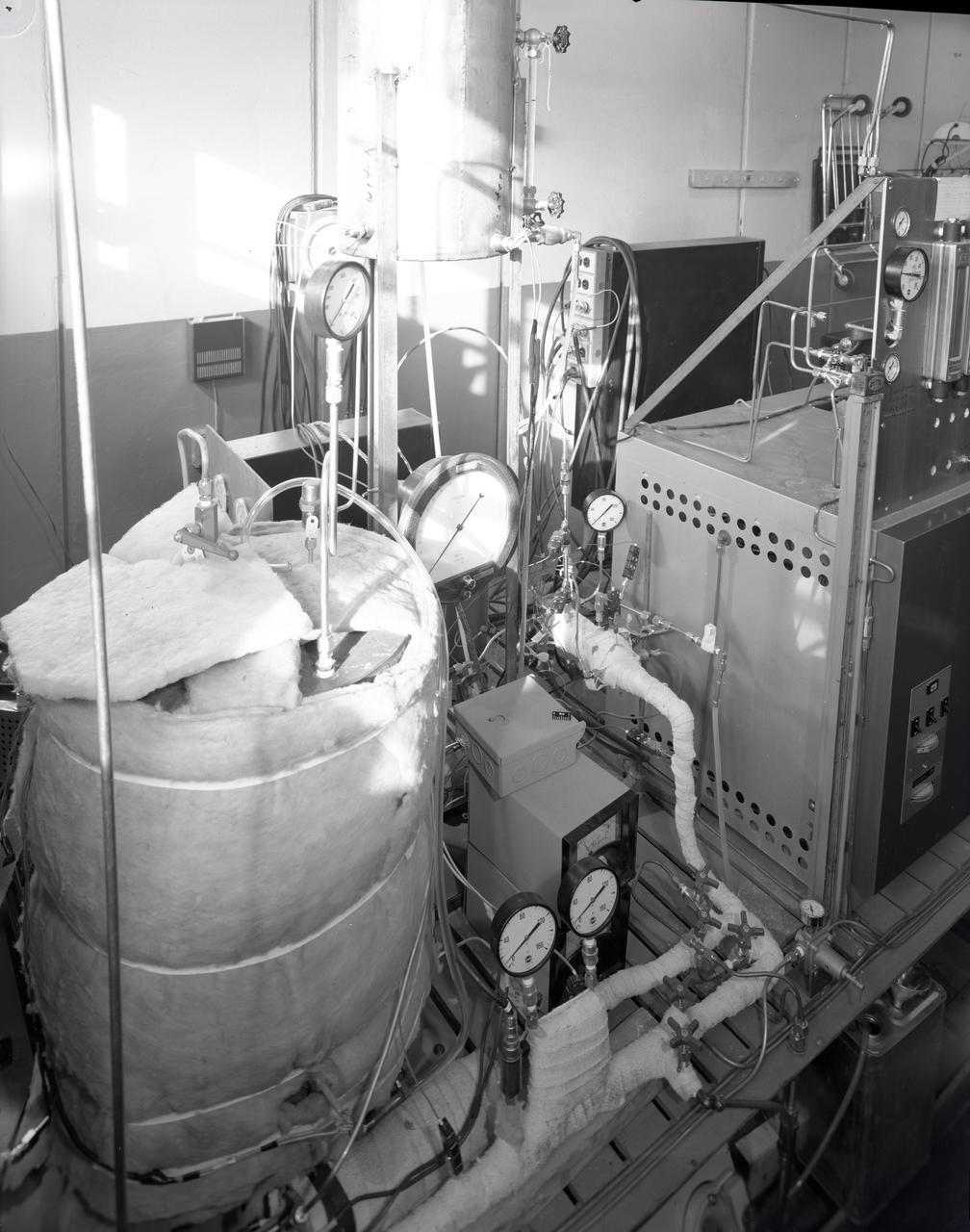
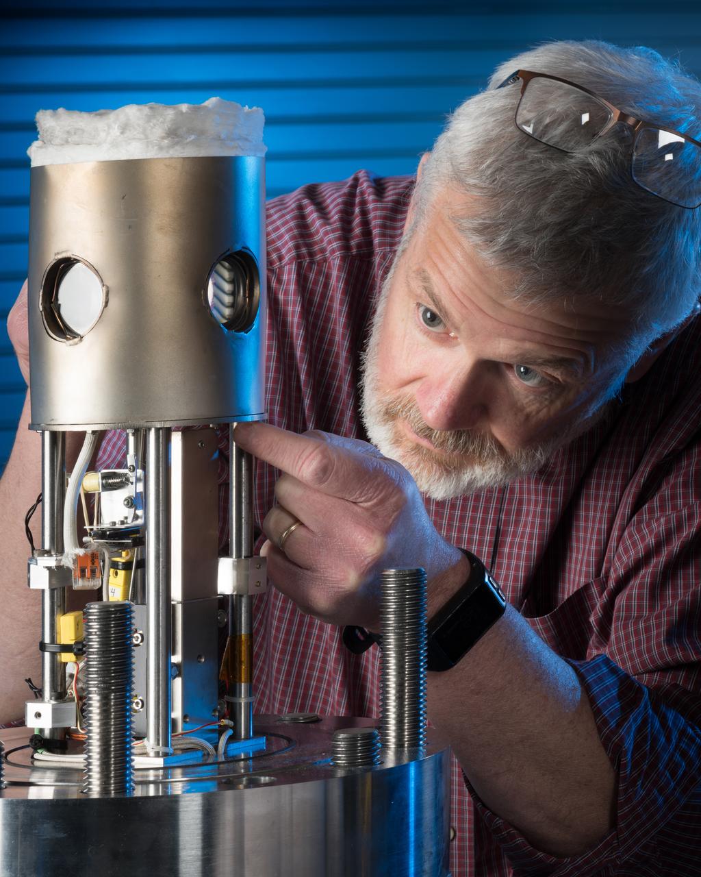
FUEL CELL CONDENSER FOR THE APOLLO SYSTEM TEST RIG
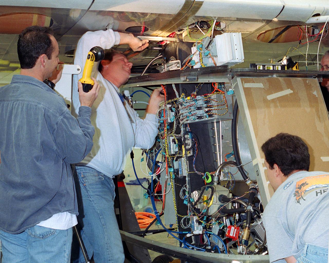
Aerovironment technicians carefully line up attachments as a fuel cell electrical system is installed on the Helios Prototype solar powered flying wing. The fuel cell system will power the aircraft at night during NASA-sponsored long-endurance demonstration flight in the summer of 2003.
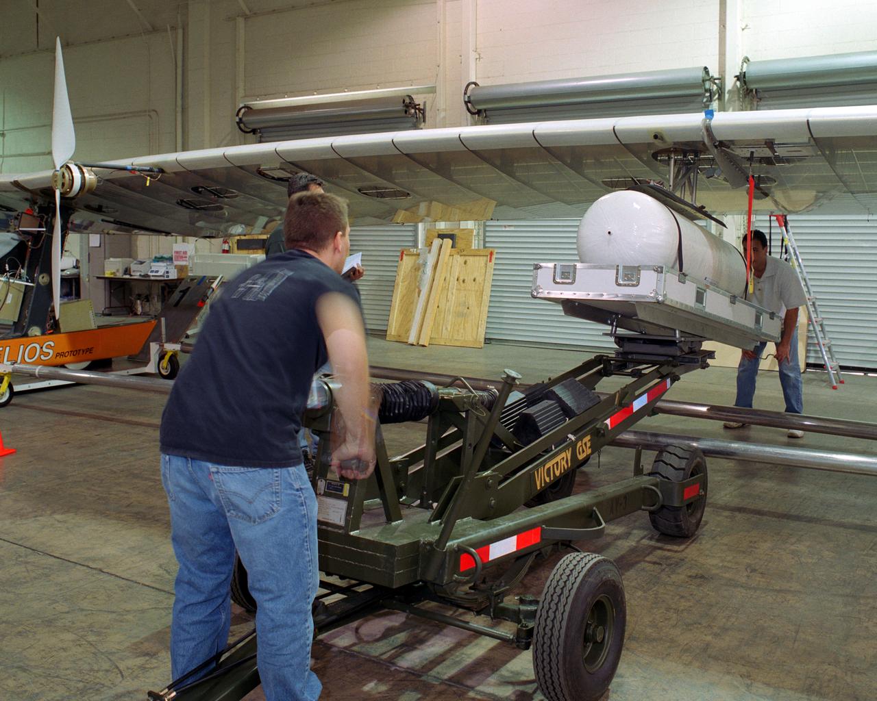
Technicians for AeroVironment, Inc., jack up a pressure tank to the wing of the Helios Prototype solar-electric flying wing. The tank carries pressurized hydrogen to fuel an experimental fuel cell system that powered the aircraft at night during an almost two-day long-endurance flight demonstration in the summer of 2003.
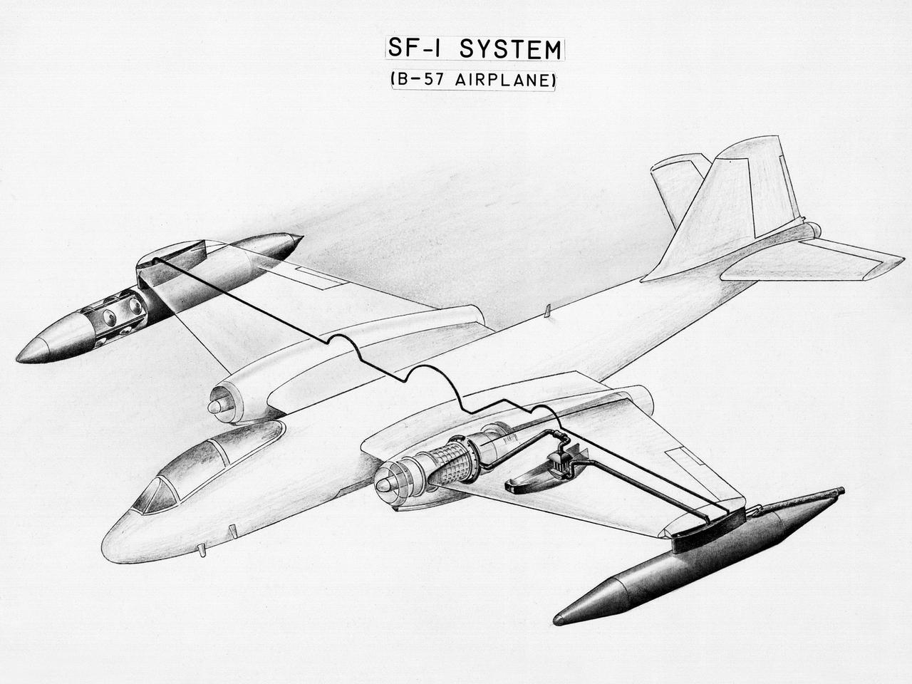
This diagram shows a hydrogen fuel system designed by researchers at the National Advisory Committee for Aeronautics (NACA) Lewis Flight Propulsion Laboratory and installed on a Martin B-57B Canberra aircraft. Lewis researchers accelerated their studies of high energy propellants in the early 1950s. In late 1954, Lewis researchers studied the combustion characteristics of gaseous hydrogen in a turbojet combustor. It was found that the hydrogen provided a very high efficiency. Almost immediately thereafter, Associate Director Abe Silverstein became focused on the possibilities of hydrogen for aircraft propulsion. That fall, Silverstein secured a contract to work with the air force to examine the practicality of liquid hydrogen aircraft. A B-57B Canberra was obtained by the air force especially for this project, referred to as Project Bee. The aircraft was powered by two Wright J65 engines, one of which was modified so that it could be operated using either traditional or liquid hydrogen propellants. The engine and its liquid hydrogen fuel system were tested extensively in the Altitude Wind Tunnel and the Four Burner Area test cells in 1955 and 1956. A B-57B flight program was planned to test the system on an actual aircraft. The aircraft would take off using jet fuel, switch to liquid hydrogen while over Lake Erie, then after burning the hydrogen supply switch back to jet fuel for the landing. The third test flight, in February 1957, was a success, and the ensuing B-57B flights remain the only demonstration of hydrogen-powered aircraft.
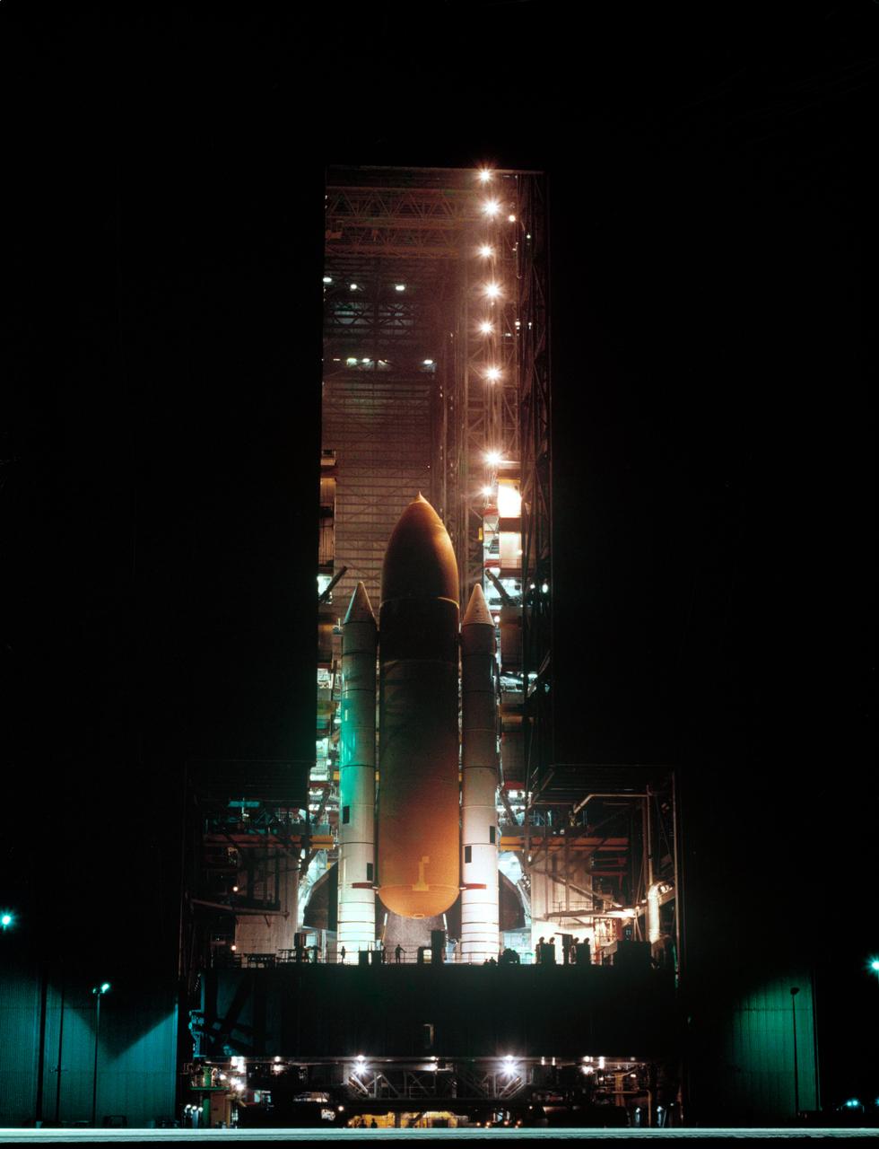
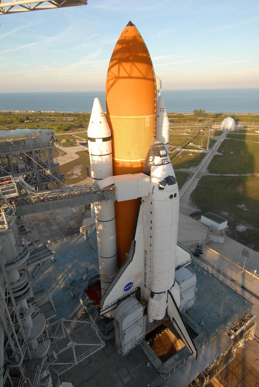
S83-39238 (1 Aug. 1983) --- The giant cluster of spaceflight hardware for NASA's eighth Space Transportation System (STS) mission begins its slow move to the launch pad at launch complex 39 at NASA's Kennedy Space Center (KSC). Following its mating to the two solid rocket boosters (SRB) and the external fuel tank (ET) in the huge vehicle assembly building (VAB), the space shuttle Challenger is slowly moved to the launch pad atop the mobile launch platform. Photo credit: NASA
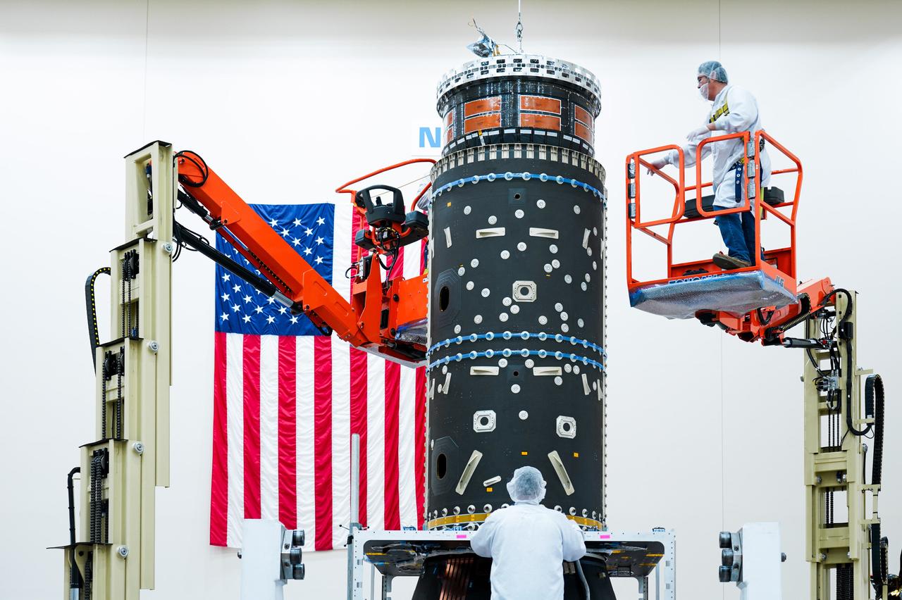
Technicians carefully install a piece of equipment to house Gateway’s xenon fuel tanks, part of its advanced electric propulsion system.
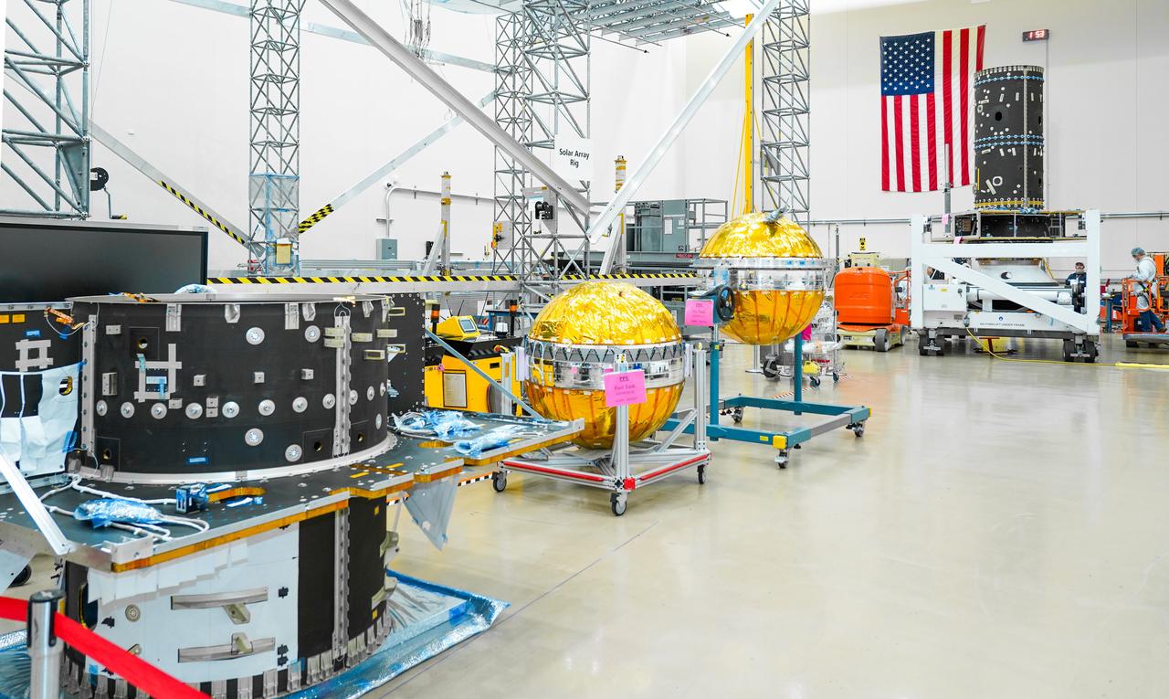
Hardware for the Gateway space station’s Power and Propulsion element, including its primary structure and fuel tanks ready for assembly, are shown at Maxar Space Systems in Palo Alto, California.
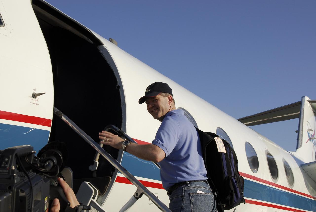
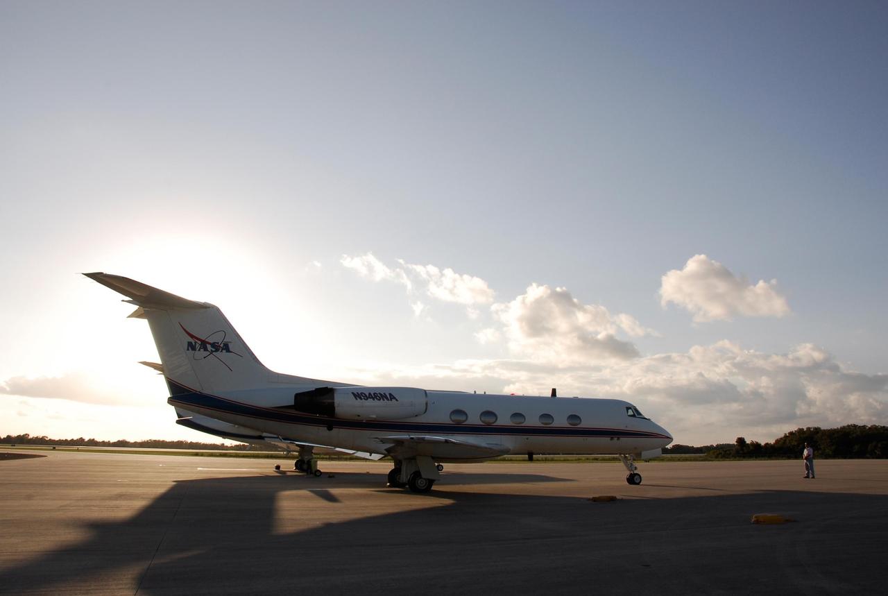
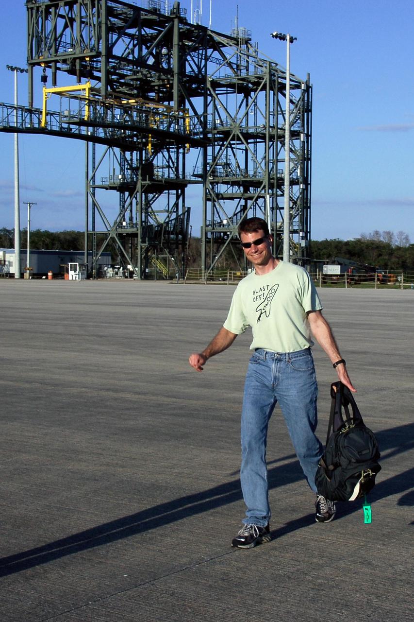
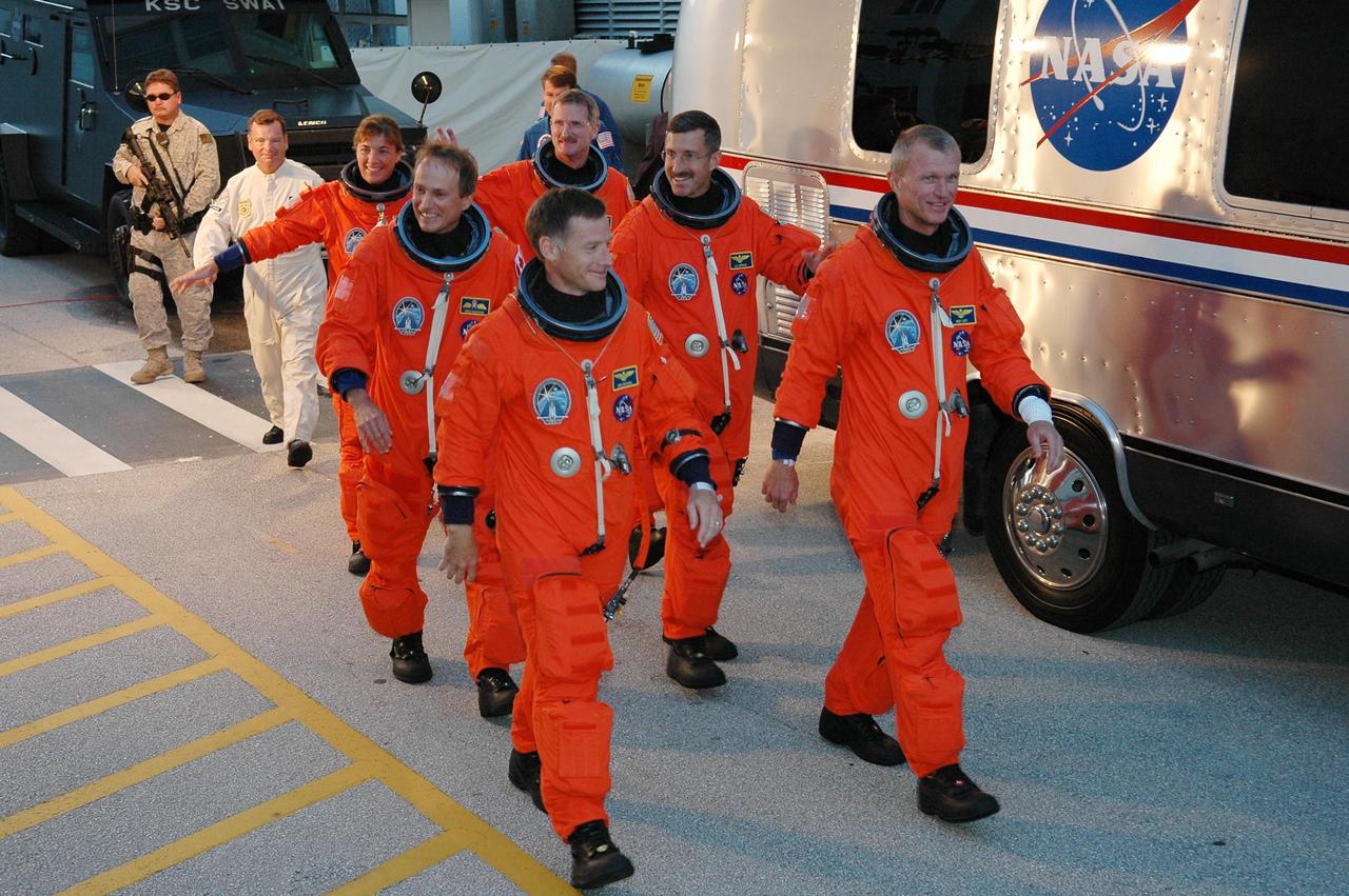
KENNEDY SPACE CENTER, FLA. -- On the Shuttle Landing Facility at NASA's Kennedy Space Center, STS-122 Commander Steve Frick heads for the plane for the return trip to Houston. The crew is flying back to Houston after launch of space shuttle Atlantis was delayed when a failure occurred in a fuel sensor system while the vehicle's external fuel tank was being filled. One of the four engine cutoff, or ECO, sensors inside the liquid hydrogen section of the tank gave a false reading and NASA's current Launch Commit Criteria require that all four sensors function properly. The sensor system is one of several that protect the shuttle's main engines by triggering their shut down if fuel runs unexpectedly low. Space shuttle Atlantis' STS-122 mission now is targeted to launch no earlier than Jan. 2. The liftoff date depends on the resolution of the problem in the fuel sensor system. Photo credit: NASA/Kim Shiflett

KENNEDY SPACE CENTER, FLA. -- On the Shuttle Landing Facility at NASA's Kennedy Space Center, STS-122 Mission Specialist Rex Walheim heads for the plane for the return trip to Houston. The crew is flying back to Houston after launch of space shuttle Atlantis was delayed when a failure occurred in a fuel sensor system while the vehicle's external fuel tank was being filled. One of the four engine cutoff, or ECO, sensors inside the liquid hydrogen section of the tank gave a false reading and NASA's current Launch Commit Criteria require that all four sensors function properly. The sensor system is one of several that protect the shuttle's main engines by triggering their shut down if fuel runs unexpectedly low. Space shuttle Atlantis' STS-122 mission now is targeted to launch no earlier than Jan. 2. The liftoff date depends on the resolution of the problem in the fuel sensor system. Photo credit: NASA/Kim Shiflett

KENNEDY SPACE CENTER, FLA. -- On the Shuttle Landing Facility at NASA's Kennedy Space Center, STS-122 Mission Specialist Leland Melvin heads for the plane for the return trip to Houston. The crew is flying back to Houston after launch of space shuttle Atlantis was delayed when a failure occurred in a fuel sensor system while the vehicle's external fuel tank was being filled. One of the four engine cutoff, or ECO, sensors inside the liquid hydrogen section of the tank gave a false reading and NASA's current Launch Commit Criteria require that all four sensors function properly. The sensor system is one of several that protect the shuttle's main engines by triggering their shut down if fuel runs unexpectedly low. Space shuttle Atlantis' STS-122 mission now is targeted to launch no earlier than Jan. 2. The liftoff date depends on the resolution of the problem in the fuel sensor system. Photo credit: NASA/Kim Shiflett
KENNEDY SPACE CENTER, FLA. -- On the Shuttle Landing Facility at NASA's Kennedy Space Center, the plane carrying the STS-122 crew taxis toward the runway for the return trip to Houston. The crew is flying back to Houston after launch of space shuttle Atlantis was delayed when a failure occurred in a fuel sensor system while the vehicle's external fuel tank was being filled. One of the four engine cutoff, or ECO, sensors inside the liquid hydrogen section of the tank gave a false reading and NASA's current Launch Commit Criteria require that all four sensors function properly. The sensor system is one of several that protect the shuttle's main engines by triggering their shut down if fuel runs unexpectedly low. Space shuttle Atlantis' STS-122 mission now is targeted to launch no earlier than Jan. 2. The liftoff date depends on the resolution of the problem in the fuel sensor system. Photo credit: NASA/Kim Shiflett

KENNEDY SPACE CENTER, FLA. -- On the Shuttle Landing Facility at NASA's Kennedy Space Center, STS-122 Pilot Alan Poindexter heads for the plane for the return trip to Houston. The crew is flying back to Houston after launch of space shuttle Atlantis was delayed when a failure occurred in a fuel sensor system while the vehicle's external fuel tank was being filled. One of the four engine cutoff, or ECO, sensors inside the liquid hydrogen section of the tank gave a false reading and NASA's current Launch Commit Criteria require that all four sensors function properly. The sensor system is one of several that protect the shuttle's main engines by triggering their shut down if fuel runs unexpectedly low. Space shuttle Atlantis' STS-122 mission now is targeted to launch no earlier than Jan. 2. The liftoff date depends on the resolution of the problem in the fuel sensor system. Photo credit: NASA/Kim Shiflett
KENNEDY SPACE CENTER, FLA. -- On the Shuttle Landing Facility at NASA's Kennedy Space Center, STS-122 Mission Specialist Stanley Love heads for the plane for the return trip to Houston. The crew is flying back to Houston after launch of space shuttle Atlantis was delayed when a failure occurred in a fuel sensor system while the vehicle's external fuel tank was being filled. One of the four engine cutoff, or ECO, sensors inside the liquid hydrogen section of the tank gave a false reading and NASA's current Launch Commit Criteria require that all four sensors function properly. The sensor system is one of several that protect the shuttle's main engines by triggering their shut down if fuel runs unexpectedly low. Space shuttle Atlantis' STS-122 mission now is targeted to launch no earlier than Jan. 2. The liftoff date depends on the resolution of the problem in the fuel sensor system. Photo credit: NASA/Kim Shiflett
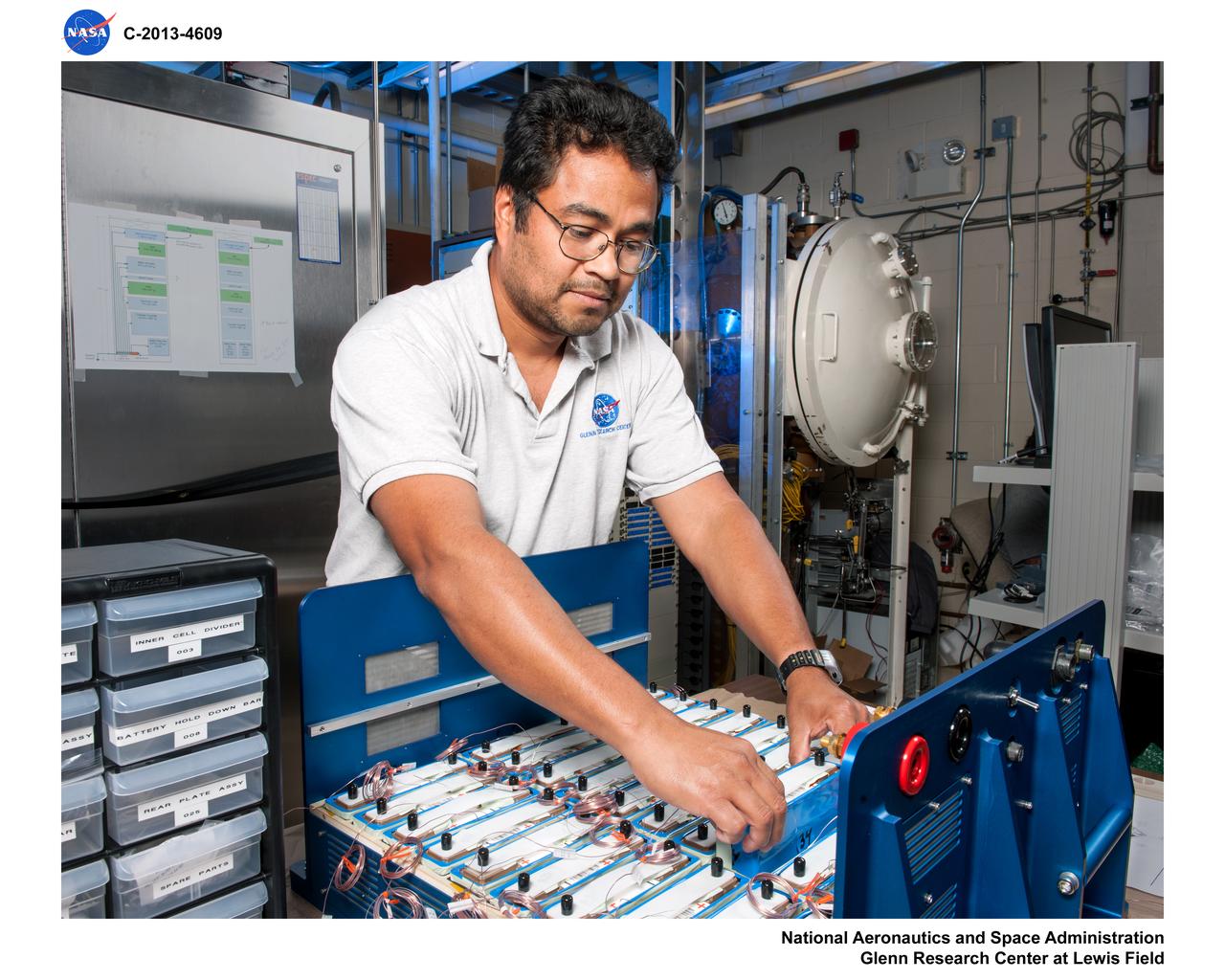
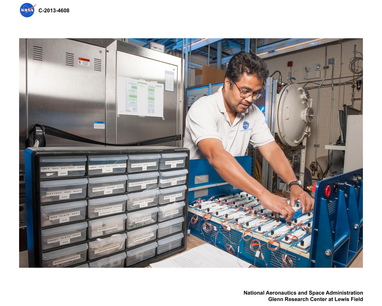
Advanced Exploration Systems (AES) Modular Power Systems for Space Exploration (AMPS); electrochemistry, AMPS, will infuse and demonstrate batteries, fuel cells, and other power modules for exploration ground system demonstrations
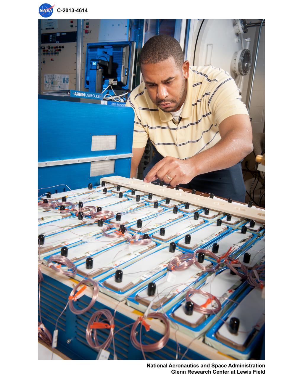
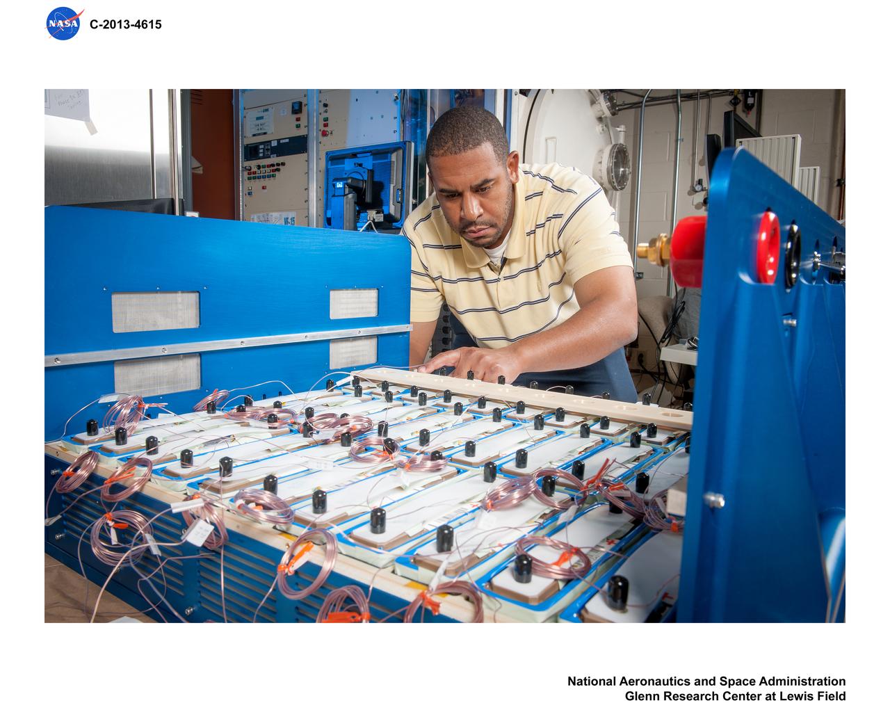
Advanced Exploration Systems (AES) Modular Power Systems for Space Exploration (AMPS); electrochemistry, AMPS, will infuse and demonstrate batteries, fuel cells, and other power modules for exploration ground system demonstrations
Advanced Exploration Systems (AES) Modular Power Systems for Space Exploration (AMPS); electrochemistry, AMPS, will infuse and demonstrate batteries, fuel cells, and other power modules for exploration ground system demonstrations
Advanced Exploration Systems (AES) Modular Power Systems for Space Exploration (AMPS); electrochemistry, AMPS, will infuse and demonstrate batteries, fuel cells, and other power modules for exploration ground system demonstrations
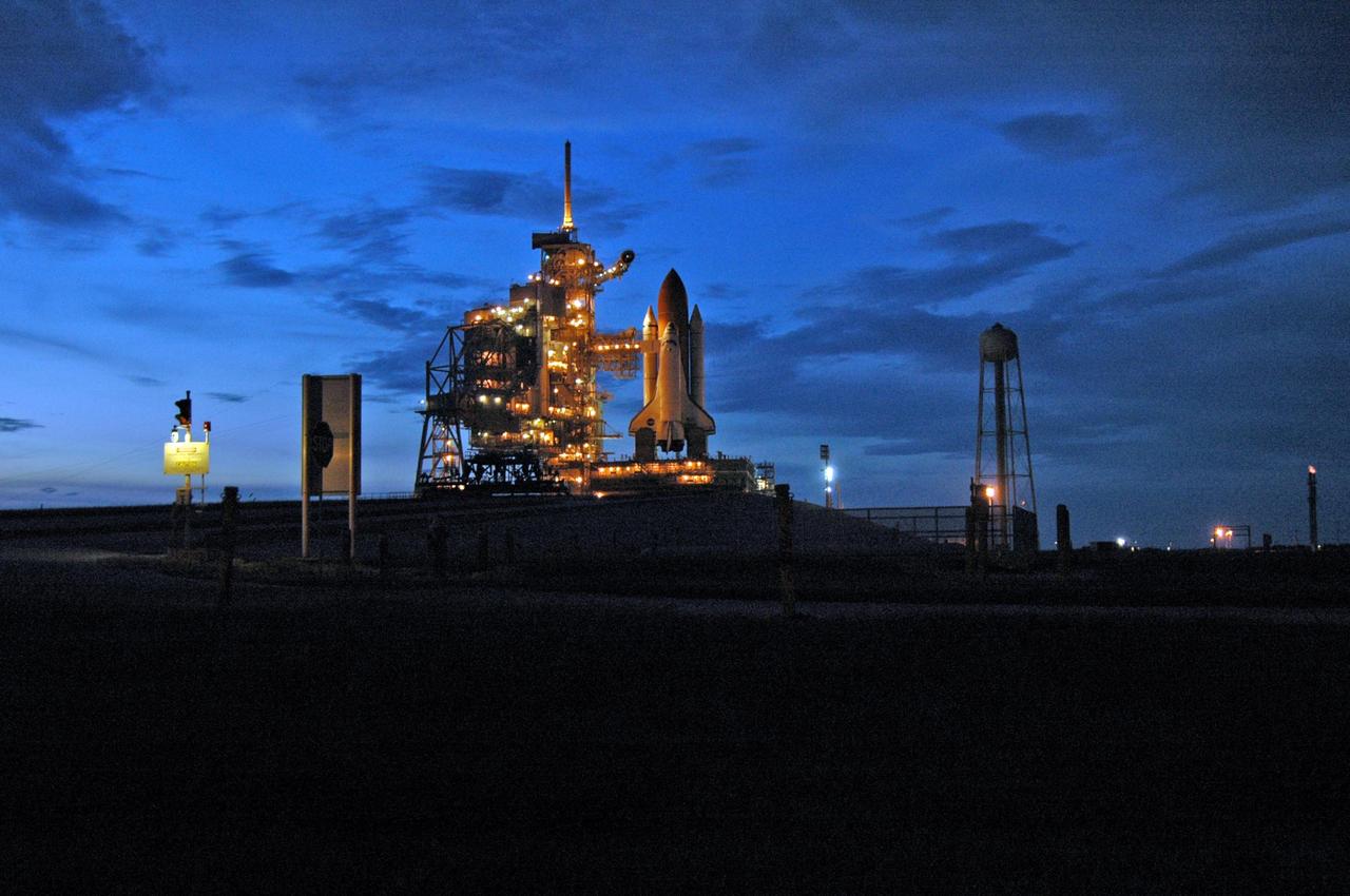
KENNEDY SPACE CENTER, FLA. - Launch Pad 39B and Space Shuttle Atlantis glow in the dusk after the morning launch was scrubbed due to a technical concern. Atlantis was scheduled to launch at 11:41 a.m. EDT Sept. 8 but was scrubbed due to an issue with a fuel cut-off sensor system inside the external fuel tank. This is one of several systems that protect the shuttle's main engines by triggering their shutdown if fuel runs unexpectedly low. This mission is the 116th space shuttle flight, the 27th flight for orbiter Atlantis, and the 19th U.S. flight to the International Space Station. STS-115 is scheduled to last 11 days with a planned landing at KSC. Photo credit: NASA/Ken Thornsley
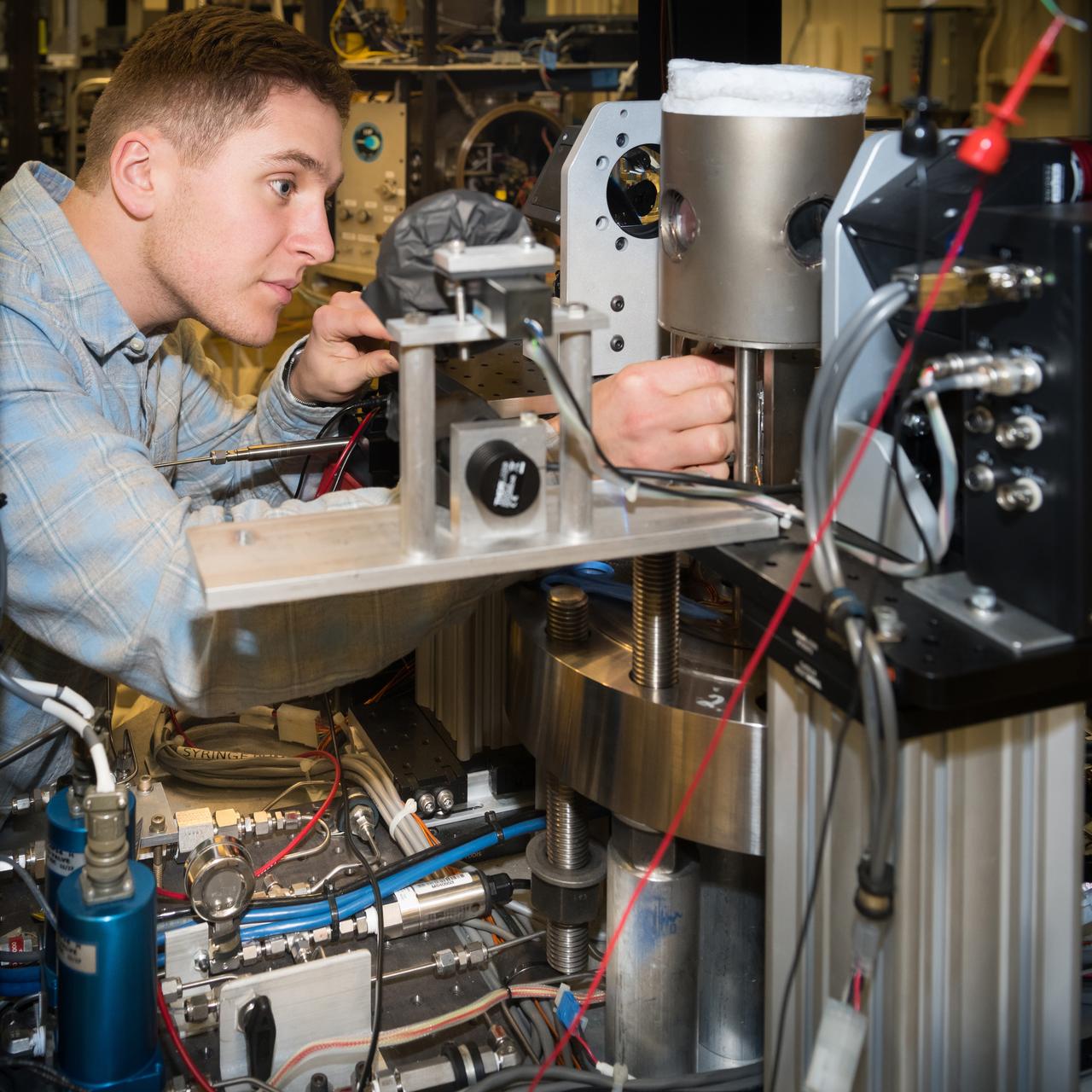
High Pressure Microgravity Combustion Experiment, HPMC, subjects liquid fuel droplets to high pressures and temperatures to study the ignition process in engine conditions, with a goal of improving fuel efficiency. In this configuration, the experiment is capable of testing droplet combustion at up to 100 atm of pressure, testing the droplet deployment system, which inserts the fuel droplet into the experiment.
High Pressure Microgravity Combustion Experiment, HPMC, subjects liquid fuel droplets to high pressures and temperatures to study the ignition process in engine conditions, with a goal of improving fuel efficiency. In this configuration, the experiment is capable of testing droplet combustion at up to 100 atm of pressure, testing the droplet deployment system, which inserts the fuel droplet into the experiment.
![A researcher at the National Advisory Committee for Aeronautics (NACA) Aircraft Engine Research Laboratory studies the fuel ignition process. Improved fuels and lubrication was an area of particular emphasis at the laboratory during World War II. The military sought to use existing types of piston engines in order to get large numbers of aircraft into the air as quickly as possible. To accomplish its goals, however, the military needed to increase the performance of these engines without having to wait for new models or extensive redesigns. The Aircraft Engine Research Laboratory was called on to lead this effort. The use of superchargers successfully enhanced engine performance, but the resulting heat increased engine knock [fuel detonation] and structural wear. These effects could be offset with improved cooling, lubrication, and fuel mixtures. The NACA researchers in the Fuels and Lubrication Division concentrated on new synthetic fuels, higher octane fuels, and fuel-injection systems. The laboratory studied 16 different types of fuel blends during the war, including extensive investigations of triptane and xylidine.](https://images-assets.nasa.gov/image/GRC-1943-C-02124/GRC-1943-C-02124~medium.jpg)
A researcher at the National Advisory Committee for Aeronautics (NACA) Aircraft Engine Research Laboratory studies the fuel ignition process. Improved fuels and lubrication was an area of particular emphasis at the laboratory during World War II. The military sought to use existing types of piston engines in order to get large numbers of aircraft into the air as quickly as possible. To accomplish its goals, however, the military needed to increase the performance of these engines without having to wait for new models or extensive redesigns. The Aircraft Engine Research Laboratory was called on to lead this effort. The use of superchargers successfully enhanced engine performance, but the resulting heat increased engine knock [fuel detonation] and structural wear. These effects could be offset with improved cooling, lubrication, and fuel mixtures. The NACA researchers in the Fuels and Lubrication Division concentrated on new synthetic fuels, higher octane fuels, and fuel-injection systems. The laboratory studied 16 different types of fuel blends during the war, including extensive investigations of triptane and xylidine.

Two F/A-18B aircraft involved in the AFF program return to base in close formation with the autonomous function disengaged.

KENNEDY SPACE CENTER, FLA. -- On the Shuttle Landing Facility at NASA's Kennedy Space Center, STS-122 Mission Specialist Leopold Eyharts heads for the plane for the return trip to Houston. The crew is flying back to Houston after launch of space shuttle Atlantis was delayed when a failure occurred in a fuel sensor system while the vehicle's external fuel tank was being filled. Eyharts was scheduled to join the Expedition 16 crew aboard the International Space Station. One of the four engine cutoff, or ECO, sensors inside the liquid hydrogen section of the tank gave a false reading and NASA's current Launch Commit Criteria require that all four sensors function properly. The sensor system is one of several that protect the shuttle's main engines by triggering their shut down if fuel runs unexpectedly low. Space shuttle Atlantis' STS-122 mission now is targeted to launch no earlier than Jan. 2. The liftoff date depends on the resolution of the problem in the fuel sensor system. Photo credit: NASA/Kim Shiflett

Technicians complete foaming around the area of Atlantis, Orbiter Vehicle (OV) 104, 17 inch diameter external tank (ET) feed line in preparation for the second liquid hydrogen tanking test at the Kennedy Space Center (KSC). An elaborate network of sensors, leak detectors, and baggies were set up on OV-104 by technicians. Engineers hope this extra instrumentation will help pinpoint the exact location of the leak. OV-104 is scheduled to be launched for the STS-38 mission, a classified Department of Defense (DOD) flight. View provided by KSC with alternate number KSC-90PC-988.
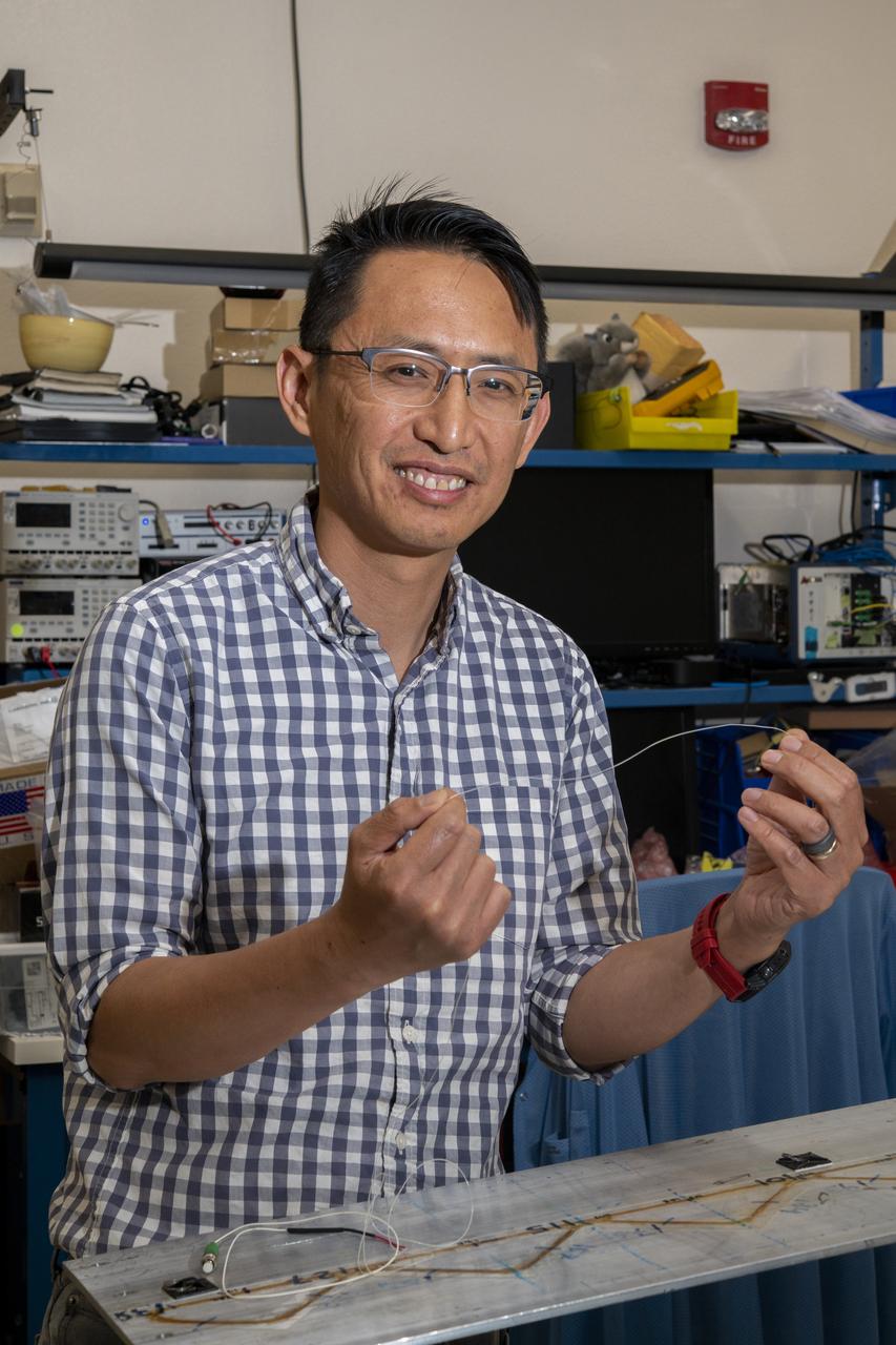
NASA’s Armstrong Flight Research Center’s FOSS, Fiber Optic Sensing System, recently supported tests of a system designed to turn oxygen into liquid oxygen, a component of rocket fuel. Patrick Chan, electronics engineer, and NASA Armstrong’s FOSS portfolio project manager, shows fiber like that used in the testing.
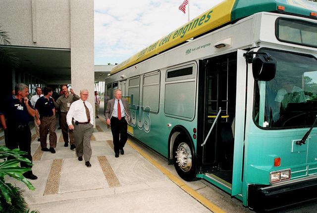
KSC workers, with Center Director Roy Bridges (at right next to bus), head for the open door of the Zero Emissions (ZE) transit bus and a ride around the center. Provided by dbb fuel cell engines inc. of Vancouver, Canada, the ZE bus was brought to KSC as part of the Center's Alternative Fuel Initiatives Program. The bus uses a Proton Exchange Membrane fuel cell in which hydrogen and oxygen, from atmospheric air, react to produce electricity that powers an electric motor drive system. The by-product "exhaust" from the fuel cell is water vapor, thus zero harmful emissions. A typical diesel-powered bus emits more than a ton of harmful pollutants from its exhaust every year. Available to employees for viewing and a ride, the ZE bus is also being used on tour routes at the KSC Visitor Complex Oct. 26-27
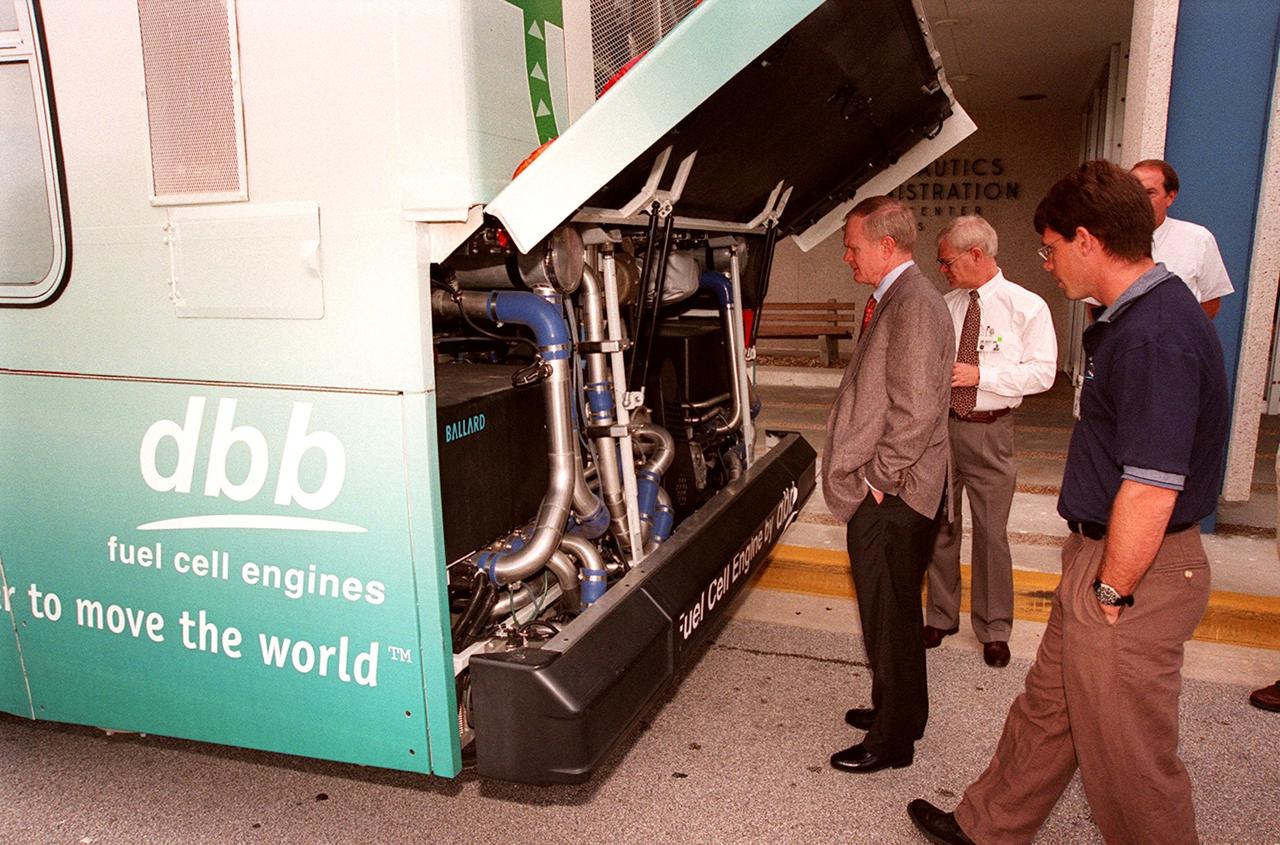
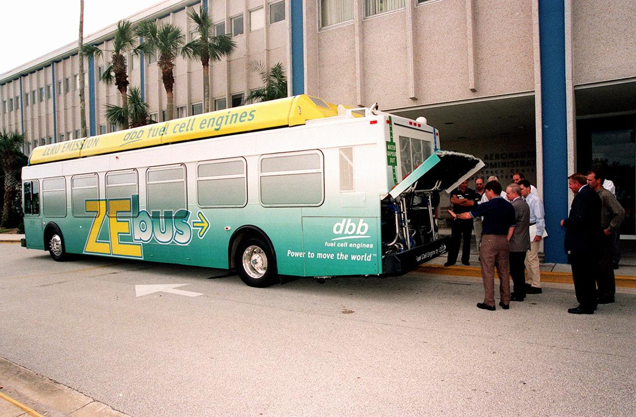
In front of the Headquarters Building at KSC, Center Director Roy Bridges (left) looks at the hydrogen-oxygen driven engine powering a Zero Emissions (ZE) transit bus. Provided by dbb fuel cell engines inc. of Vancouver, Canada, the ZE bus was brought to KSC as part of the Center's Alternative Fuel Initiatives Program. The bus uses a Proton Exchange Membrane fuel cell in which hydrogen and oxygen, from atmospheric air, react to produce electricity that powers an electric motor drive system. The by-product "exhaust" from the fuel cell is water vapor, thus zero harmful emissions. A typical diesel-powered bus emits more than a ton of harmful pollutants from its exhaust every year. Available for viewing by employees, the ZE bus is also being used on tour routes at the KSC Visitor Complex Oct. 26-27
On view in front of the Headquarters Building, the Zero Emissions (ZE) transit bus attracts an interested group of employees, including Center Director Roy Bridges (second from left in foreground). Provided by dbb fuel cell engines inc. of Vancouver, Canada, the ZE bus was brought to KSC as part of the Center's Alternative Fuel Initiatives Program. The bus uses a Proton Exchange Membrane fuel cell in which hydrogen and oxygen, from atmospheric air, react to produce electricity that powers an electric motor drive system. The by-product "exhaust" from the fuel cell is water vapor, thus zero harmful emissions. A typical diesel-powered bus emits more than a ton of harmful pollutants from its exhaust every year. Available for viewing by employees, the ZE bus is also being used on tour routes at the KSC Visitor Complex Oct. 26-27
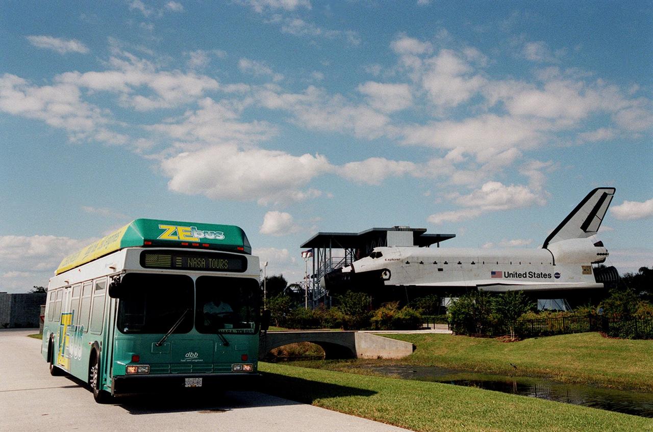
The Zero Emissions (ZE) transit bus passes a mock-up orbiter named Explorer on a trek through the KSC Visitor Complex. Provided by dbb fuel cell engines inc. of Vancouver, Canada, the ZE bus was brought to KSC as part of the Center's Alternative Fuel Initiatives Program. The bus uses a Proton Exchange Membrane fuel cell in which hydrogen and oxygen, from atmospheric air, react to produce electricity that powers an electric motor drive system. The by-product "exhaust" from the fuel cell is water vapor, thus zero harmful emissions. A typical diesel-powered bus emits more than a ton of harmful pollutants from its exhaust every year. The ZE bus is being used on tour routes at the KSC Visitor Complex for two days to introduce the public to the concept
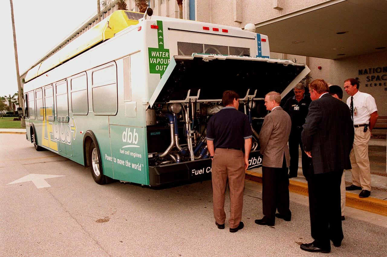
KSC employees, along with Center Director Roy Bridges (second from left), view the hydrogen-oxygen driven engine powering a Zero Emissions (ZE) transit bus. Provided by dbb fuel cell engines inc. of Vancouver, Canada, the ZE bus was brought to KSC as part of the Center's Alternative Fuel Initiatives Program. The bus uses a Proton Exchange Membrane fuel cell in which hydrogen and oxygen, from atmospheric air, react to produce electricity that powers an electric motor drive system. The by-product "exhaust" from the fuel cell is water vapor, thus zero harmful emissions. A typical diesel-powered bus emits more than a ton of harmful pollutants from its exhaust every year. Available for viewing by employees, the ZE bus is also being used on tour routes at the KSC Visitor Complex Oct. 26-27
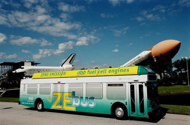
The Zero Emissions (ZE) transit bus tours the KSC Visitor Complex for a test ride. In the background are a mock-up orbiter named Explorer (left) and a stack of solid rocket boosters and external tank (right), typically used on Shuttle launches. Provided by dbb fuel cell engines inc. of Vancouver, Canada, the ZE bus was brought to KSC as part of the Center's Alternative Fuel Initiatives Program. The bus uses a Proton Exchange Membrane fuel cell in which hydrogen and oxygen, from atmospheric air, react to produce electricity that powers an electric motor drive system. The by-product "exhaust" from the fuel cell is water vapor, thus zero harmful emissions. A typical diesel-powered bus emits more than a ton of harmful pollutants from its exhaust every year. The ZE bus is being used on tour routes at the KSC Visitor Complex for two days to introduce the public to the concept

Inside the Launch Control Center’s Firing Room 1 at NASA’s Kennedy Space Center in Florida, members of the Artemis I launch team rehearse the procedures for fueling the Space Launch System (SLS) rocket with super cold propellants, or cryogenics, on Aug. 18, 2020. During the cryogenic simulation, potential problem scenarios were introduced to test the tools, processes, and procedures necessary for fueling the rocket. Artemis I will be the first integrated test flight of SLS and the Orion spacecraft – the system that will ultimately land the first woman and the next man on the Moon by 2024.

Inside the Launch Control Center’s Firing Room 1 at NASA’s Kennedy Space Center in Florida, members of the Artemis I launch team rehearse the procedures for fueling the Space Launch System (SLS) rocket with super cold propellants, or cryogenics, on Aug. 18, 2020. During the cryogenic simulation, potential problem scenarios were introduced to test the tools, processes, and procedures necessary for fueling the rocket. Artemis I will be the first integrated test flight of SLS and the Orion spacecraft – the system that will ultimately land the first woman and the next man on the Moon by 2024.

Inside the Launch Control Center’s Firing Room 1 at NASA’s Kennedy Space Center in Florida, members of the Artemis I launch team rehearse the procedures for fueling the Space Launch System (SLS) rocket with super cold propellants, or cryogenics, on Aug. 18, 2020. During the cryogenic simulation, potential problem scenarios were introduced to test the tools, processes, and procedures necessary for fueling the rocket. Artemis I will be the first integrated test flight of SLS and the Orion spacecraft – the system that will ultimately land the first woman and the next man on the Moon by 2024.

Inside the Launch Control Center’s Firing Room 1 at NASA’s Kennedy Space Center in Florida, members of the Artemis I launch team rehearse the procedures for fueling the Space Launch System (SLS) rocket with super cold propellants, or cryogenics, on Aug. 18, 2020. During the cryogenic simulation, potential problem scenarios were introduced to test the tools, processes, and procedures necessary for fueling the rocket. Artemis I will be the first integrated test flight of SLS and the Orion spacecraft – the system that will ultimately land the first woman and the next man on the Moon by 2024.

Inside the Launch Control Center’s Firing Room 1 at NASA’s Kennedy Space Center in Florida, members of the Artemis I launch team rehearse the procedures for fueling the Space Launch System (SLS) rocket with super cold propellants, or cryogenics, on Aug. 18, 2020. During the cryogenic simulation, potential problem scenarios were introduced to test the tools, processes, and procedures necessary for fueling the rocket. Artemis I will be the first integrated test flight of SLS and the Orion spacecraft – the system that will ultimately land the first woman and the next man on the Moon by 2024.
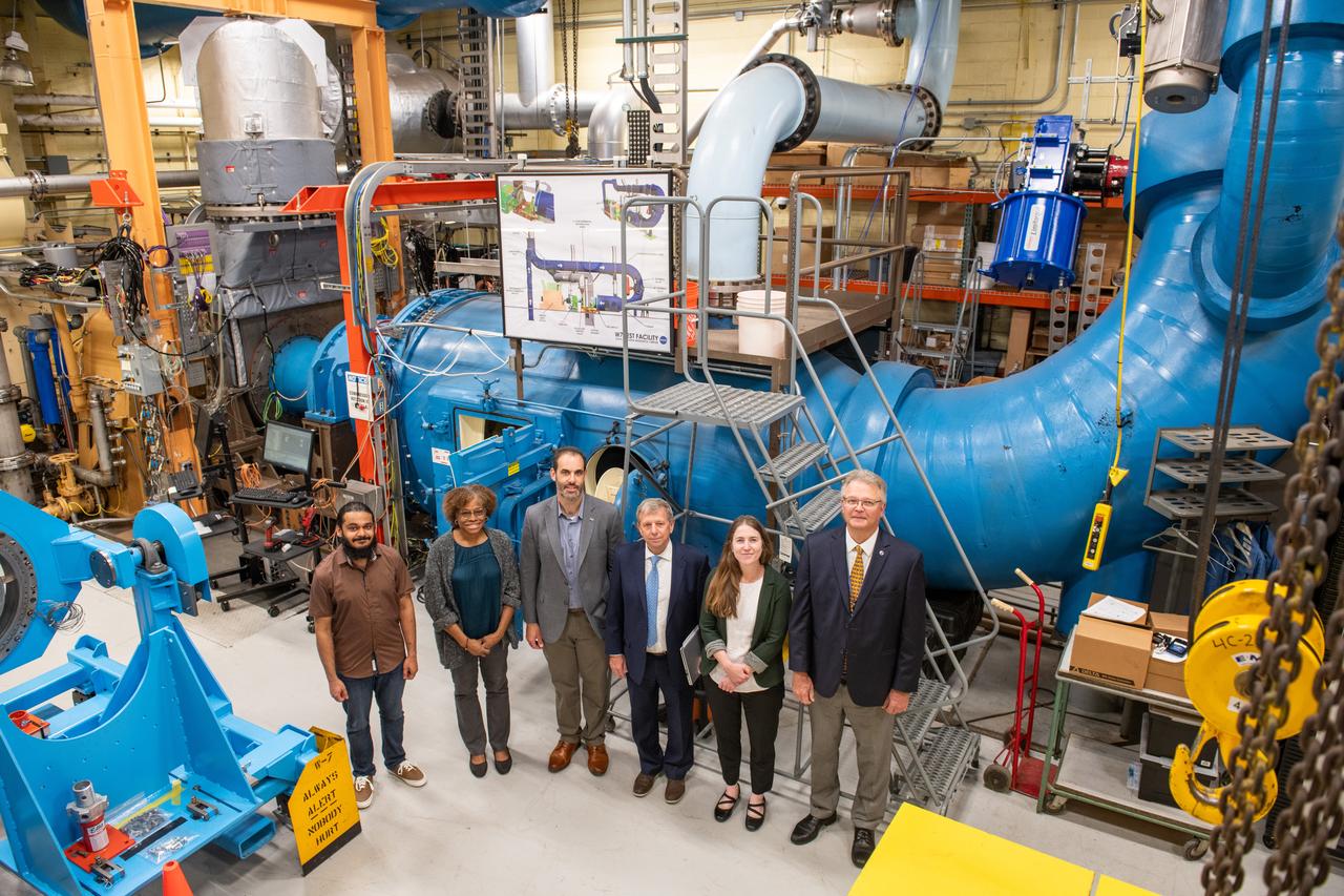
Tour of the Hybrid Thermally Efficient Core (HyTEC) Facility on June 17, 2024 at Glenn Research Center. Pictured in the photo is Sameer Kulkarni, Concha Reid, Tony Nerone, Tibor Kremic and Dr. Katherine Calvin, and W. Allen Kilgore. The Hybrid Thermally Efficient Core (HyTEC) project is working with industry partners to develop small core engine technologies to enable fuel burn reductions, additional use of electric airplane systems through power extracted from the engine, and advance engine operability and compatibility with sustainable aviation fuels.
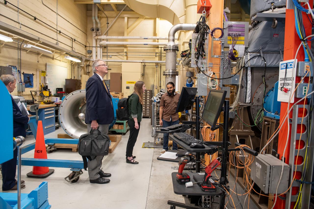
Tour of the Hybrid Thermally Efficient Core (HyTEC) Facility on June 17th, 2024 at Glenn Research Center. The Hybrid Thermally Efficient Core (HyTEC) project is working with industry partners to develop small core engine technologies to enable fuel burn reductions, additional use of electric airplane systems through power extracted from the engine, and advance engine operability and compatibility with sustainable aviation fuels.
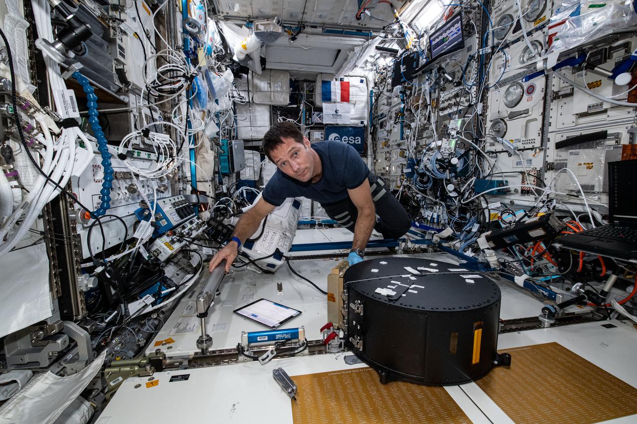
iss065e084793 (June 1, 2021) --- Expedition 65 Flight Engineer Thomas Pesquet of ESA (European Space Agency) works inside the Columbus laboratory module to closeout the Fluidics study. The fluid physics investigation, sponsored by ESA, may lead to the development of better fuel systems for satellites and provide for longer satellite lifetime by better managing use of fuel for maneuvering.
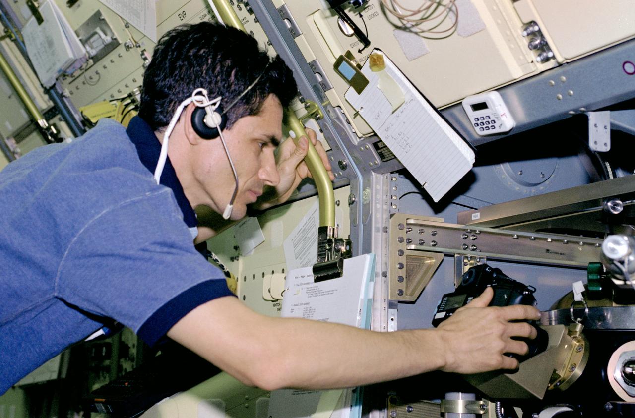
STS083-312-017 (4-8 April 1997) --- Payload specialist Gregory T. Linteris sets up a 35mm camera, one of three photographic/recording systems on the Drop Combustion Experiment (DCE) Apparatus. DCE is an enclosed chamber in which Helium-Oxygen fuel mixtures are injected and burned as single droplets. Combustion of fuel droplets is an important part of many operations, home heating, power production by gas turbines and combustion of gasoline in an automobile engine.

KENNEDY SPACE CENTER, FLA. - A KSC employee stops to look at a car equipped to use natural gas as fuel. Several cars using alternative fuel technology were part of an exhibit during KSC’s annual Environmental and Energy Awareness Week, held April 20-22. The slogan for this year’s event was “Today's Conservation Defines Tomorrow's Future.” Presentations included Chemistry Safety, Cost-Effective Solar Applications, Non-Native Invasive Plant Identification and Control, Energy Efficient Lighting Systems, and Historical Changes in KSC’s Ecosystems.

Tour of the Hybrid Thermally Efficient Core (HyTEC) Facility on June 17, 2024 at Glenn Research Center. Pictured in the photo is Tony Nerone, W. Allen Kilgore, Dr. Katherine Calvin, and Sameer Kulkarni. The Hybrid Thermally Efficient Core (HyTEC) project is working with industry partners to develop small core engine technologies to enable fuel burn reductions, additional use of electric airplane systems through power extracted from the engine, and advance engine operability and compatibility with sustainable aviation fuels.
KENNEDY SPACE CENTER, FLA. -- Shadows spill across space shuttle Atlantis, still poised on the pad after its launch on mission STS-122 was postponed Thursday. In the background is the Atlantic Ocean. Shuttle program managers decided at 9:56 a.m. to postpone the launch because of an issue with a fuel cut-off sensor system inside the external fuel tank. This is one of several systems that protect the shuttle's main engines by triggering their shut down if fuel runs unexpectedly low. During countdown activities this morning, two sensors failed a routine prelaunch check. There are four engine cut-off, or ECO, sensors inside the liquid hydrogen section of the tank, and Launch Commit Criteria require three of the four sensor systems to be functioning properly. The tank's liquid oxygen and liquid hydrogen was drained from the tank, and preparations will begin for a possible launch attempt Friday. NASA's launch rules have a preplanned procedure that states in the case of ECO sensor system failure, engineers need to drain the tank and verify all the sensors are working as they go dry. Atlantis carries the Columbus Laboratory, the European Space Agency's largest contribution to the construction of the space station. When permanently attached to Node 2, the laboratory will carry out experiments in materials science, fluid physics and biosciences, as well as perform a number of technological applications, in a microgravity environment. Photo credit: NASA/George Shelton
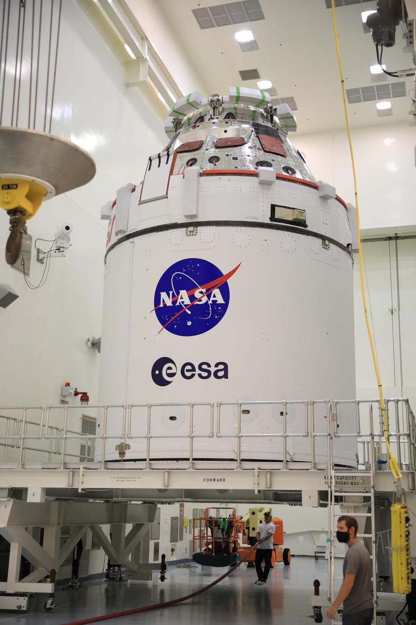
Fueling and servicing checks on the Orion spacecraft for the Artemis I mission are completed inside Kennedy Space Center’s Multi-Payload Processing Facility on July 8, 2021. The capsule will be transported to the Florida spaceport’s Launch Abort System Facility, where teams with Exploration Ground Systems and contractor Jacobs will work to add parts of the launch abort system onto the spacecraft. Launching later this year, Artemis I will be a test of the Orion spacecraft and SLS rocket as an integrated system ahead of crewed flights to the Moon.
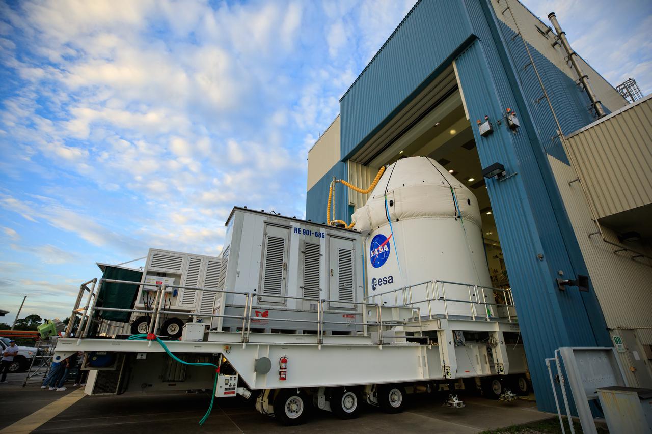
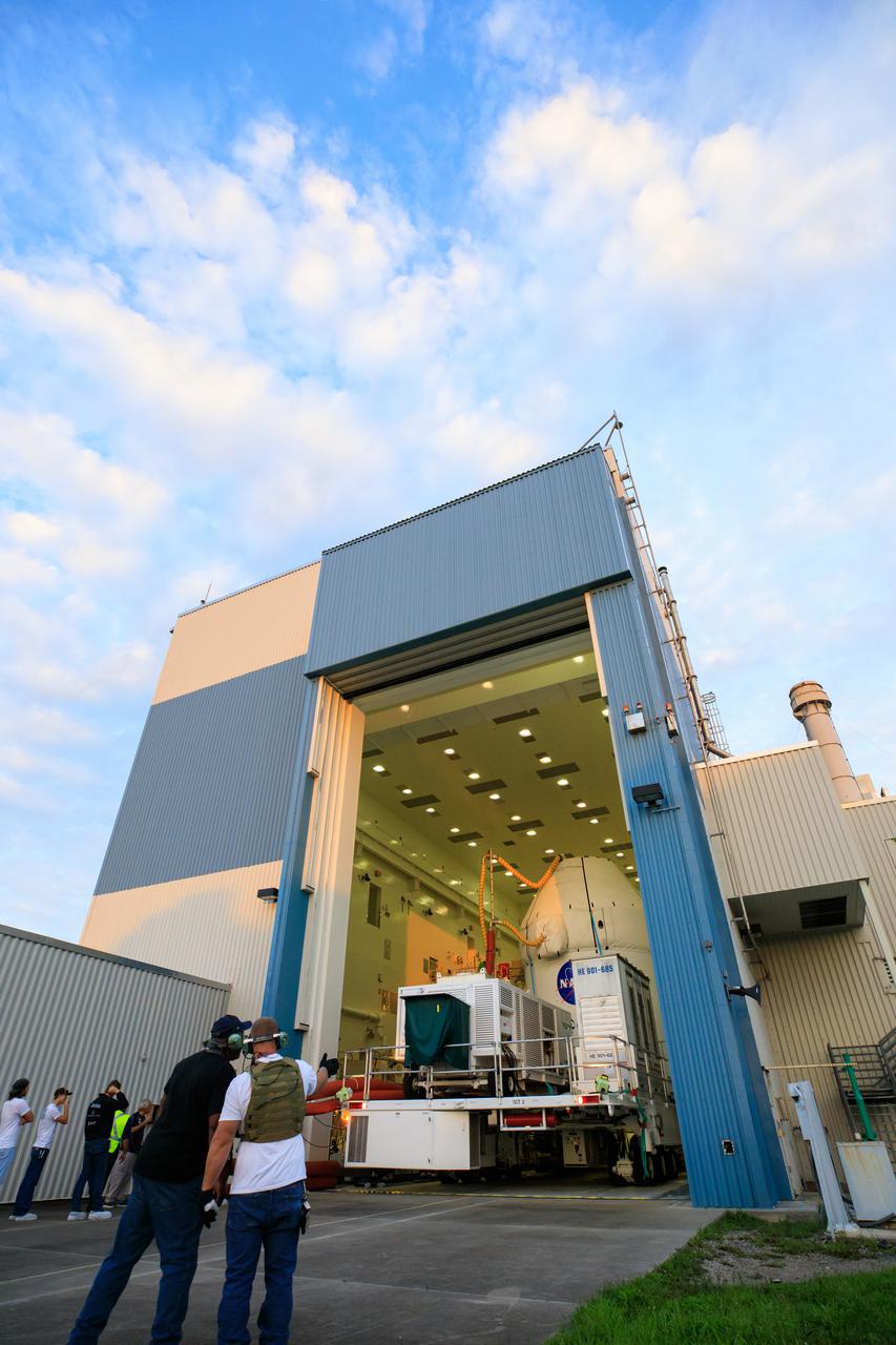
After recently completing fueling and servicing checks, the Orion spacecraft for the Artemis I mission departs from Kennedy Space Center’s Multi-Payload Processing on July 10, 2021. It is being transported to the Florida spaceport’s Launch Abort System Facility, where teams with Exploration Ground Systems and contractor Jacobs will integrate components of the launch abort system onto the spacecraft. Launching later this year, Artemis I will be a test of the Orion spacecraft and SLS rocket as an integrated system ahead of crewed flights to the Moon.
After recently completing fueling and servicing checks, the Orion spacecraft for the Artemis I mission departs from Kennedy Space Center’s Multi-Payload Processing on July 10, 2021. It is being transported to the Florida spaceport’s Launch Abort System Facility, where teams with Exploration Ground Systems and contractor Jacobs will integrate components of the launch abort system onto the spacecraft. Launching later this year, Artemis I will be a test of the Orion spacecraft and SLS rocket as an integrated system ahead of crewed flights to the Moon.
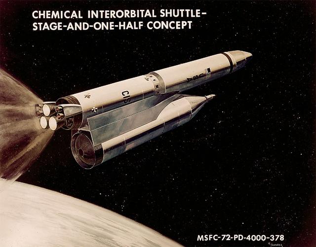
In 1970, NASA initiated Phase A contracts to study alternate Space Shuttle designs in addition to the two-stage fully-reusable Space Shuttle system already under development. A number of alternate systems were developed to ensure the development of the optimum earth-to-orbit system, including the Stage-and-a-half Chemical Interorbital Shuttle, shown here. The concept would utilize a reusable marned spacecraft with an onboard propulsion system attached to an expendable fuel tank to provide supplementary propellants.
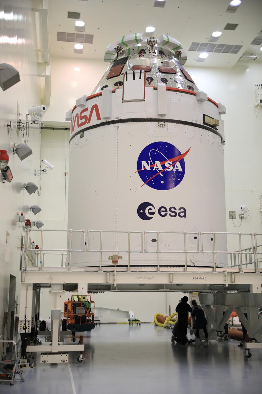
Fueling and servicing checks on the Orion spacecraft for the Artemis I mission are completed inside Kennedy Space Center’s Multi-Payload Processing Facility on July 8, 2021. The capsule will be transported to the Florida spaceport’s Launch Abort System Facility, where teams with Exploration Ground Systems and contractor Jacobs will work to add parts of the launch abort system onto the spacecraft. Launching later this year, Artemis I will be a test of the Orion spacecraft and SLS rocket as an integrated system ahead of crewed flights to the Moon.
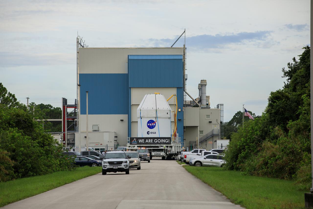
After recently completing fueling and servicing checks, the Orion spacecraft for the Artemis I mission departs Kennedy Space Center’s Multi-Payload Processing on July 10, 2021. The capsule is being transported to the Florida spaceport’s Launch Abort System Facility, where teams with Exploration Ground Systems and contractor Jacobs will integrate components of the launch abort system onto the spacecraft. Launching later this year, Artemis I will be a test of the Orion spacecraft and SLS rocket as an integrated system ahead of crewed flights to the Moon.
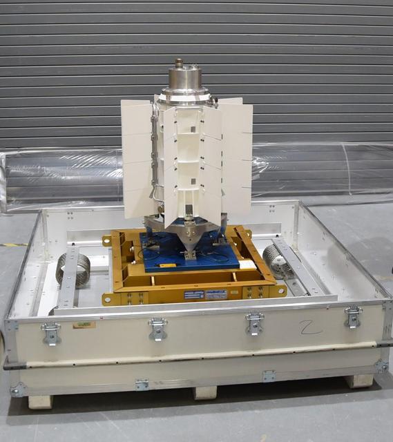
The electricity for NASA's Mars 2020 rover is provided by a power system called a Multi-Mission Radioisotope Thermoelectric Generator, or MMRTG. Essentially a nuclear battery, an MMRTG uses the heat from the natural radioactive decay of plutonium-238 to generate about 110 watts of electricity at the start of a mission. Besides generating electrical power, the MMRTG produces heat. Some of this heat can be used to maintain the rover's systems at the proper operating temperatures in the frigid cold of space and on the surface of Mars. This device, seen here before fueling and testing at the U.S. Department of Energy's Idaho National Laboratory, has "fins" that radiate excess heat. MMRTGs are provided to NASA for civil space applications by the U.S. Department of Energy (DOE). The radioisotope fuel is inserted into the MMRTG at the DOE's Idaho National Laboratory before the MMRTG is shipped to the launch site. Electrically heated versions of the MMRTG are used at JPL to verify and practice integration of the power system with the rover. https://photojournal.jpl.nasa.gov/catalog/PIA23306
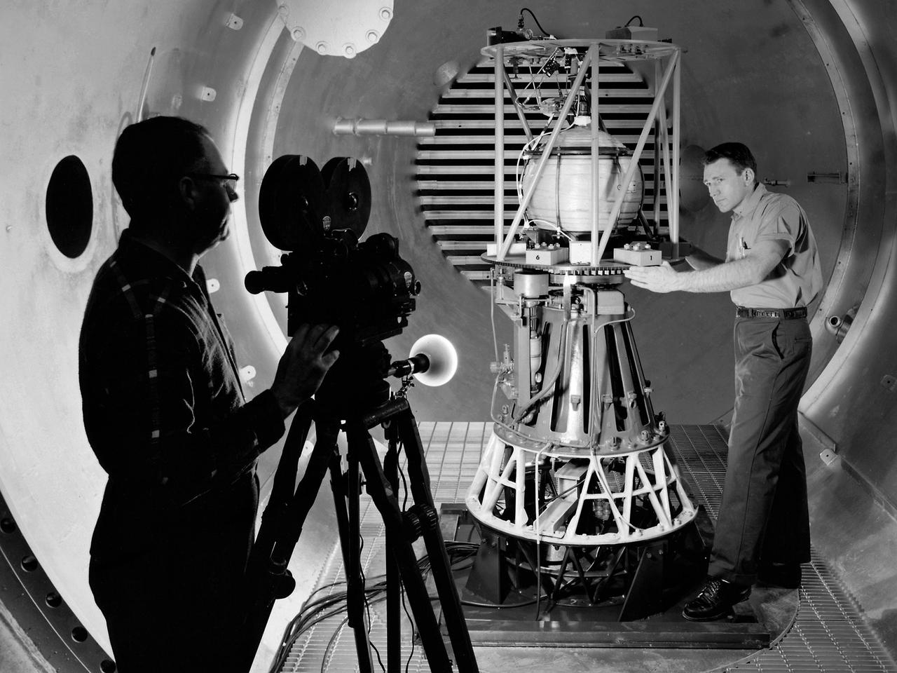
Mechanic Howard Wine inspects the setup of a spin isolator in Cell 2 of the Propulsion Systems Laboratory at the National Aeronautics and Space Administration (NASA) Lewis Research Center. Photographer Al Jecko filmed the proceedings. This test was unique in that the chamber’s altitude system was used, but not its inlet air flow. The test was in preparation for an upcoming launch of modified liquid hydrogen propellant tank on a sounding rocket. This Weightlessness Analysis Sounding Probe (WASP) was part of Lewis investigation into methods for controlling partially filled liquid hydrogen fuel tanks during flight. Second-stage rockets, the Centaur in particular, were designed to stop their engines and coast, then restart them when needed. During this coast period, the propellant often shifted inside the tank. This movement could throw the rocket off course or result in the sloshing of fuel away from the fuel pump. Wine was one of only three journeymen mechanics at Lewis when he was hired in January 1954. He spent his first decade in the Propulsion Systems Laboratory and was soon named a section head. Wine went on to serve as Assistant Division Chief and later served as an assistant to the director. Jecko joined the center in 1947 as a photographer and artist. He studied at the Cleveland School or Art and was known for his cartoon drawing. He worked at the center for 26 years.
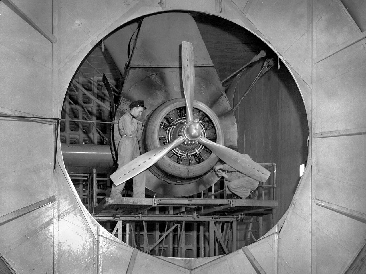
A Wright Aeronautical R–2600 Cyclone piston engine installed in the Engine Propeller Research Building, or Prop House, at the National Advisory Committee for Aeronautics (NACA) Aircraft Engine Research Laboratory. The R–2600 was among the most powerful engines that emerged during World War II. The engine, which was developed for commercial applications in 1939, was used to power the North American B–25 bomber and several other midsize military aircraft. The higher altitudes required by the military caused problems with the engine's cooling and fuel systems. The military requested that the Aircraft Engine Research Laboratory analyze the performance of the R–2600, improve its cooling system, and reduce engine knock. The NACA researchers subjected the engine to numerous tests in its Prop House. The R–2600 was the subject of the laboratory's first technical report, which was written by members of the Fuels and Lubricants Division. The Prop House contained soundproof test cells in which piston engines and propellers were mounted and operated at high powers. Electrically driven fans drew air through ducts to create a stream of cooling air over the engines. Researchers tested the performance of fuels, turbochargers, water-injection and cooling systems here during World War II. The facility was also investigated a captured German V–I buzz bomb during the war.
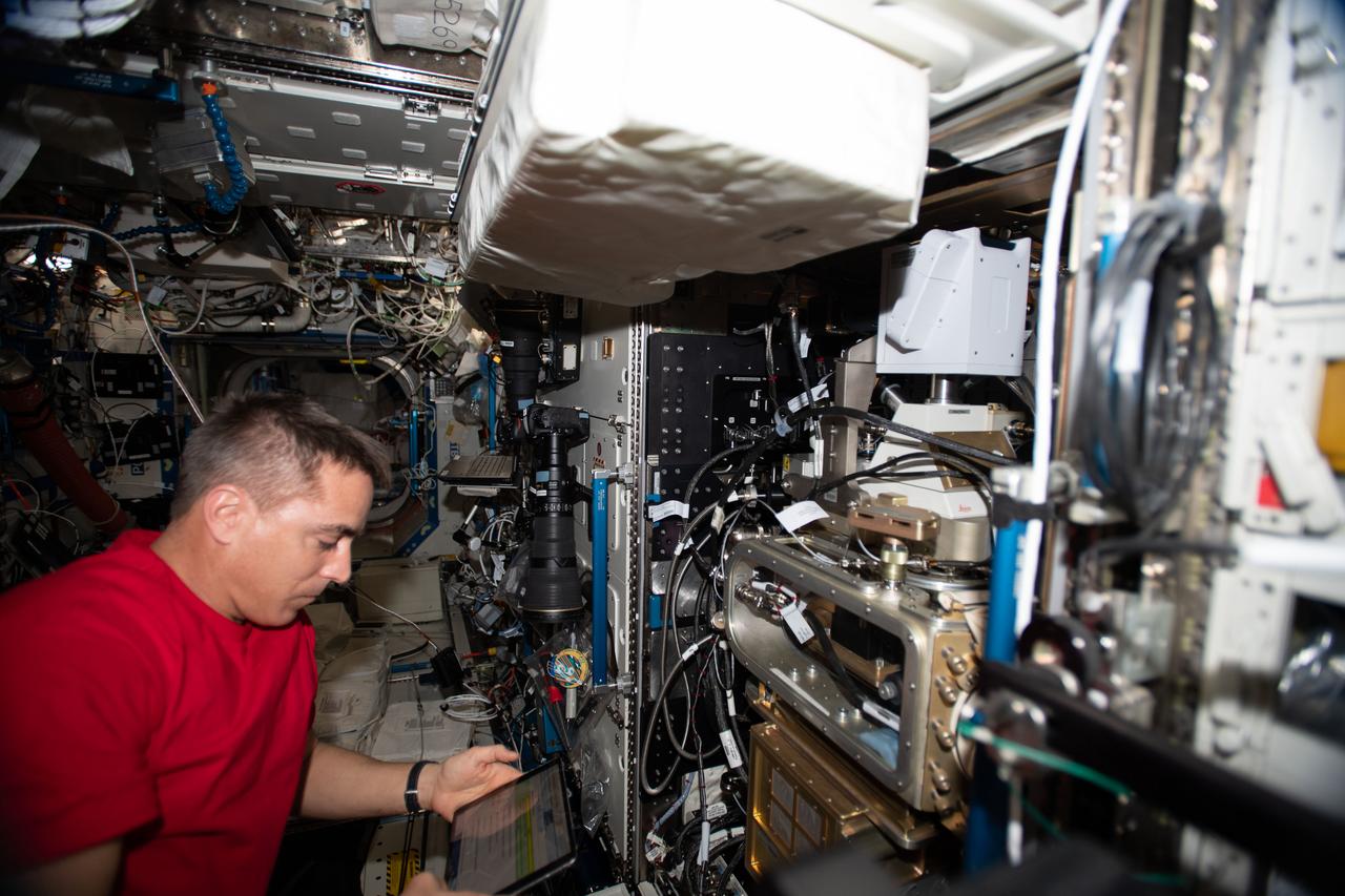
iss063e001782 (April 21, 2020) --- NASA astronaut and Expedition 63 Commander Chris Cassidy works on the Fluids Integrated Rack (FIR) replacing components in the research device that studies the behavior of fluids in microgravity. The FIR will help promote the design of advanced space-based fuel tanks and other complex fluid transfer systems.

The Space Shuttle main propulsion system includes three major elements. One of those elements is the External Tank (ET). The ET holds over one-half million gallons of liquid oxygen and liquid hydrogen that fuel the main engines.
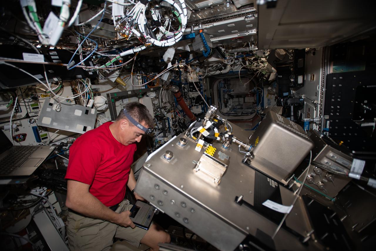
iss063e001804 (April 21, 2020) --- NASA astronaut and Expedition 63 Commander Chris Cassidy works on the Fluids Integrated Rack (FIR) replacing components in the research device that studies the behavior of fluids in microgravity. The FIR will help promote the design of advanced space-based fuel tanks and other complex fluid transfer systems.
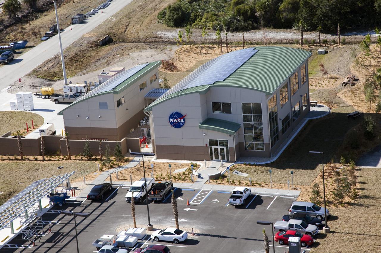
CAPE CANAVERAL, Fla. -- The Propellants North Administrative and Maintenance Facility in the Launch Complex 39 area of NASA's Kennedy Space Center in Florida is ready for business. The environmentally friendly facility is slated to be NASA's second Platinum-rated by the U.S. Green Building Council's (USGBC) Leadership in Environmental and Energy Design (LEED) certification system. It will be the space agency's first carbon-neutral facility, which means it will produce enough energy onsite from renewable sources to offset what it requires to operate. On the right is the facility's two-story administrative building, which will house managers, mechanics and technicians who fuel spacecraft at Kennedy. On the left is a single-story shop that will be used to store cryogenic fuel transfer equipment. In the parking lot is a solar-powered parking station for alternative fuel vehicles. Photo credit: NASA/Frank Michaux
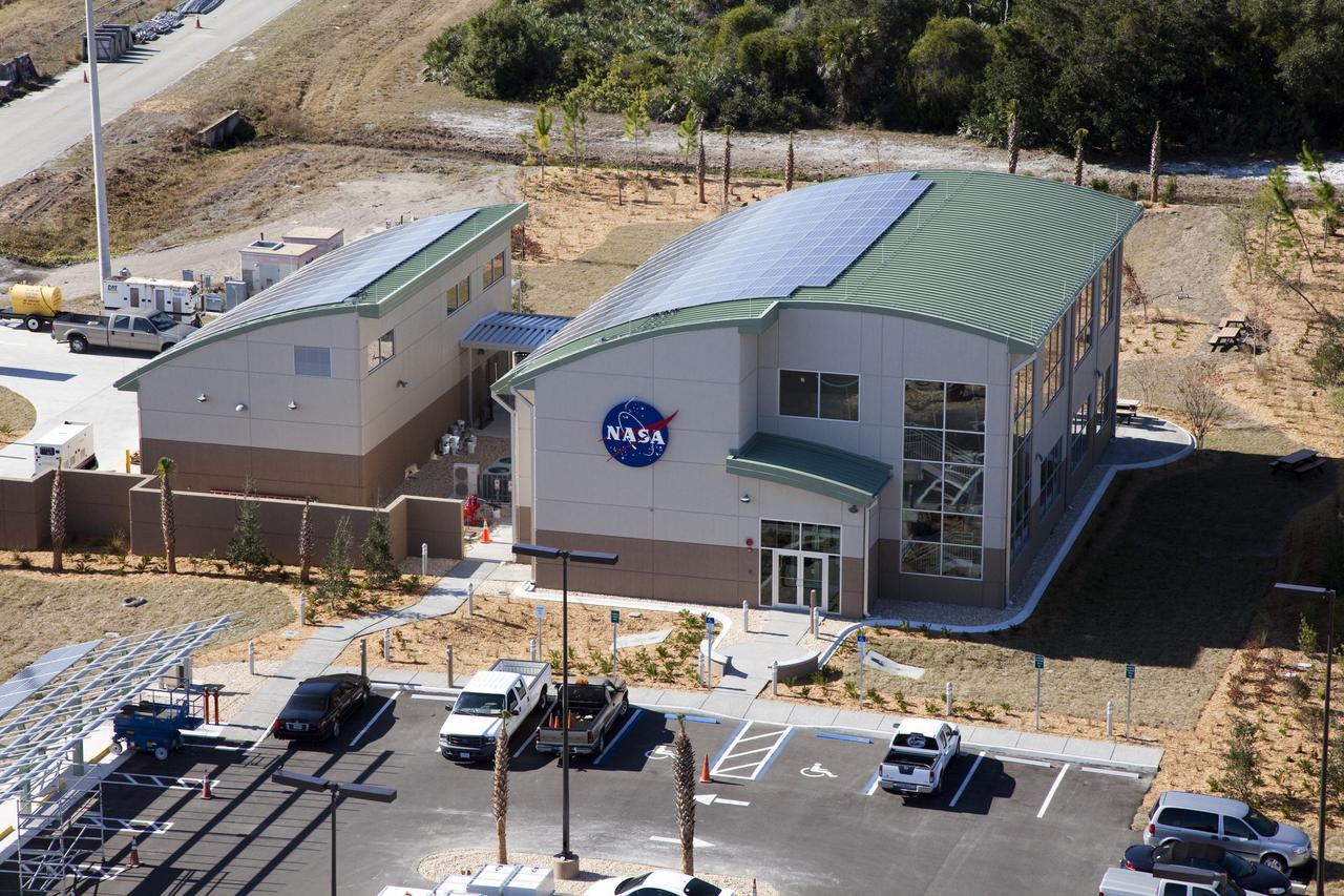
CAPE CANAVERAL, Fla. -- The Propellants North Administrative and Maintenance Facility in the Launch Complex 39 area of NASA's Kennedy Space Center in Florida is ready for business. The environmentally friendly facility is slated to be NASA's second Platinum-rated by the U.S. Green Building Council's (USGBC) Leadership in Environmental and Energy Design (LEED) certification system. It will be the space agency's first carbon-neutral facility, which means it will produce enough energy onsite from renewable sources to offset what it requires to operate. On the right is the facility's two-story administrative building, which will house managers, mechanics and technicians who fuel spacecraft at Kennedy. On the left is a single-story shop that will be used to store cryogenic fuel transfer equipment. In the parking lot is a solar-powered parking station for alternative fuel vehicles. Photo credit: NASA/Frank Michaux
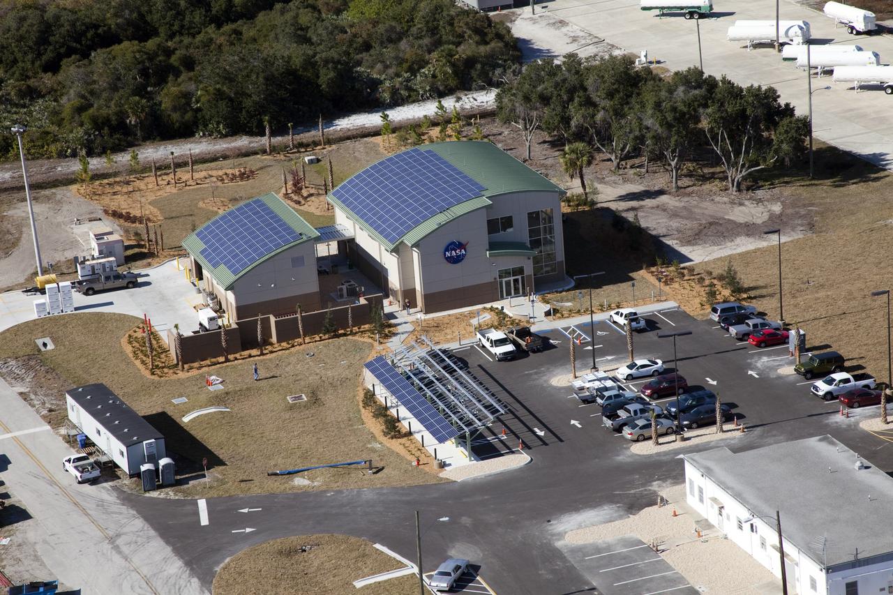
CAPE CANAVERAL, Fla. -- The Propellants North Administrative and Maintenance Facility in the Launch Complex 39 area of NASA's Kennedy Space Center in Florida is ready for business. The environmentally friendly facility is slated to be NASA's second Platinum-rated by the U.S. Green Building Council's (USGBC) Leadership in Environmental and Energy Design (LEED) certification system. It will be the space agency's first carbon-neutral facility, which means it will produce enough energy onsite from renewable sources to offset what it requires to operate. On the right is the facility's two-story administrative building, which will house managers, mechanics and technicians who fuel spacecraft at Kennedy. On the left is a single-story shop that will be used to store cryogenic fuel transfer equipment. In the parking lot is a solar-powered parking station for alternative fuel vehicles. Photo credit: NASA/Frank Michaux

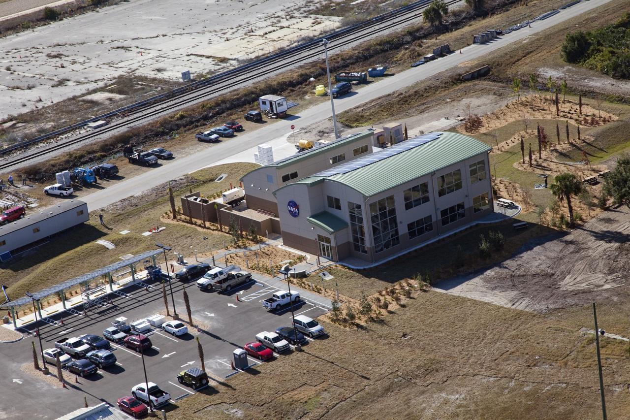
CAPE CANAVERAL, Fla. -- This is the back view of the new Propellants North Administrative and Maintenance Facility in the Launch Complex 39 area of NASA's Kennedy Space Center in Florida. The environmentally friendly facility is slated to be NASA's second Platinum-rated by the U.S. Green Building Council's (USGBC) Leadership in Environmental and Energy Design (LEED) certification system. It will be the space agency's first carbon-neutral facility, which means it will produce enough energy onsite from renewable sources to offset what it requires to operate. On the right is the facility's single-story shop that will be used to store cryogenic fuel transfer equipment. On the left is a two-story administrative building, which will house managers, mechanics and technicians who fuel spacecraft at Kennedy. In the parking lot is a solar-powered parking station for alternative fuel vehicles. Photo credit: NASA/Frank Michaux
CAPE CANAVERAL, Fla. -- The Propellants North Administrative and Maintenance Facility in the Launch Complex 39 area of NASA's Kennedy Space Center in Florida is ready for business. The environmentally friendly facility is slated to be NASA's second Platinum-rated by the U.S. Green Building Council's (USGBC) Leadership in Environmental and Energy Design (LEED) certification system. It will be the space agency's first carbon-neutral facility, which means it will produce enough energy onsite from renewable sources to offset what it requires to operate. On the right is the facility's two-story administrative building, which will house managers, mechanics and technicians who fuel spacecraft at Kennedy. On the left is a single-story shop that will be used to store cryogenic fuel transfer equipment. In the parking lot is a solar-powered parking station for alternative fuel vehicles. Photo credit: NASA/Frank Michaux

CAPE CANAVERAL, Fla. -- The Vehicle Assembly Building towers over the new Propellants North Administrative and Maintenance Facility in the Launch Complex 39 area of NASA's Kennedy Space Center in Florida. The environmentally friendly facility is slated to be NASA's second Platinum-rated by the U.S. Green Building Council's (USGBC) Leadership in Environmental and Energy Design (LEED) certification system. It will be the space agency's first carbon-neutral facility, which means it will produce enough energy onsite from renewable sources to offset what it requires to operate. On the right is the facility's two-story administrative building, which will house managers, mechanics and technicians who fuel spacecraft at Kennedy. On the left is a single-story shop that will be used to store cryogenic fuel transfer equipment. In the parking lot is a solar-powered parking station for alternative fuel vehicles. Photo credit: NASA/Frank Michaux
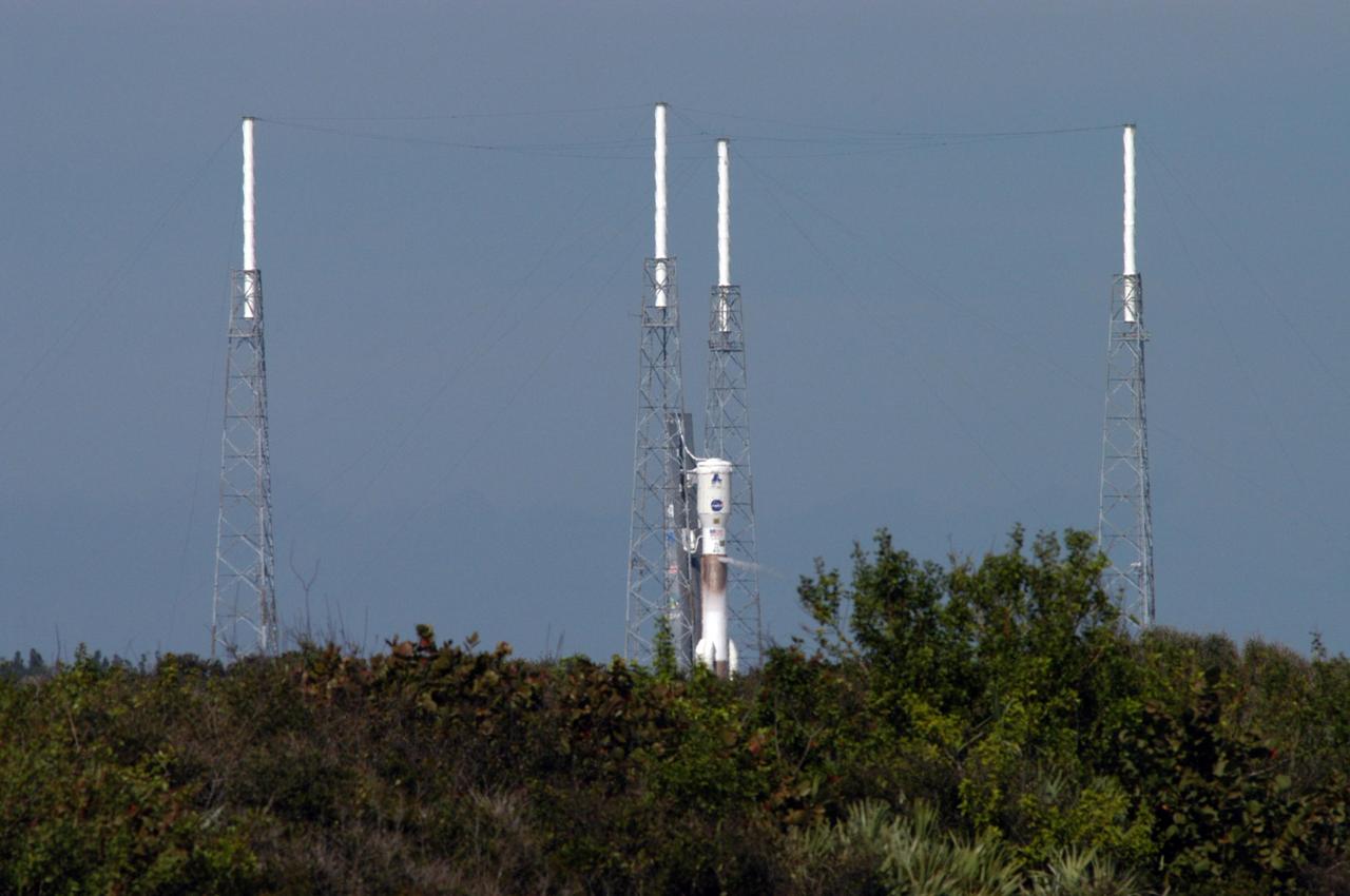
KENNEDY SPACE CENTER, FLA. - The Lockheed Martin Atlas V rocket (center) undergoes a tanking test on Launch Complex 41 at Cape Canaveral Air Force Station in Florida. The rocket was fully fueled with liquid hydrogen, liquid oxygen and RP 1 kerosene fuel. Seen surrounding the rocket are lightning towers that support the catenary wire that provides lightning protection. The Atlas V is the launch vehicle for NASA’s New Horizons spacecraft, scheduled to launch during a 35-day window that opens Jan. 11, and fly through the Pluto system as early as summer 2015.
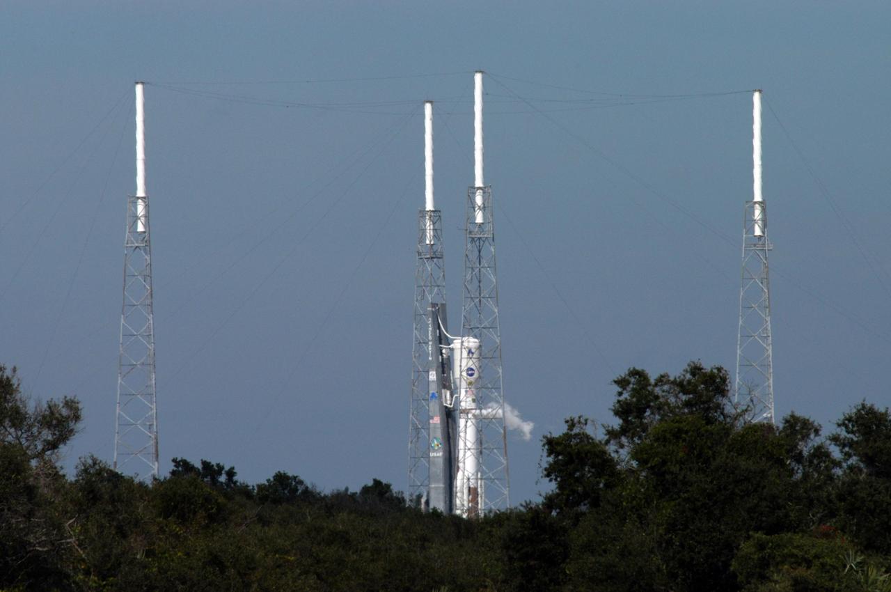
KENNEDY SPACE CENTER, FLA. - The Lockheed Martin Atlas V rocket (center) undergoes a tanking test on Launch Complex 41 at Cape Canaveral Air Force Station in Florida. The rocket was fully fueled with liquid hydrogen, liquid oxygen and RP 1 kerosene fuel. Seen surrounding the rocket are lightning towers that support the catenary wire that provides lightning protection. The Atlas V is the launch vehicle for NASA’s New Horizons spacecraft, scheduled to launch during a 35-day window that opens Jan. 11, and fly through the Pluto system as early as summer 2015.

Image taken on card 15 during BASS-II flame test session with reduced O2 partial pressure. Session conducted on GMT 214. The Burning and Suppression of Solids - II (BASS-II) investigation examines the burning and extinction characteristics of a wide variety of fuel samples in microgravity. The BASS-II experiment will guide strategies for materials flammability screening for use in spacecraft as well as provide valuable data on solid fuel burning behavior in microgravity. BASS-II results contribute to the combustion computational models used in the design of fire detection and suppression systems in microgravity and on Earth.
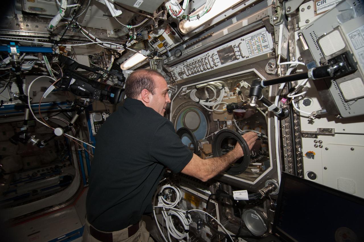
ISS039-E-005726 (27 March 2014) --- Expedition 39 Flight Engineer Rick Mastracchio performs inflight maintenance on an experiment called Burning and Suppression of Solids (BASS)-II. The investigation examines the burning and extinction characteristics of a wide variety of fuel samples in microgravity. The BASS-II experiment will guide strategies for materials flammability screening for use in spacecraft as well as provide valuable data on solid fuel burning behavior in microgravity. BASS-II results contribute to the combustion computational models used in the design of fire detection and suppression systems in microgravity and on Earth.
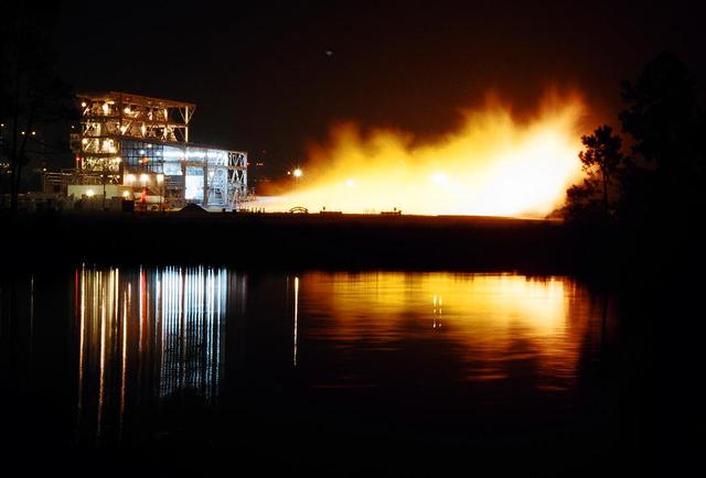
Gaseous hydrogen is burned off at the E1 Test Stand the night of Oct. 7 during a cold-flow test of the fuel turbopump of the Integrated Powerhead Demonstrator (IPD) at NASA Stennis Space Center (SSC). The gaseous hydrogen spins the pump's turbine during the test, which was conducted to verify the pump's performance. Engineers plan one more test before sending the pump to The Boeing Co. for inspection. It will then be returned to SSC for engine system assembly. The IPD is the first reusable hydrogen-fueled advanced engine in development since the Space Shuttle Main Engine.
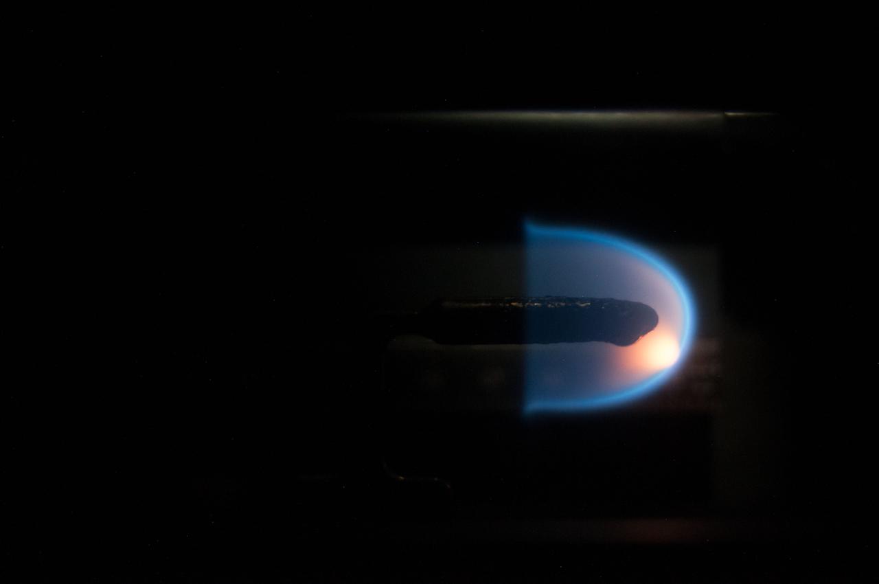
Image taken on card 8 during BASS-II flame test session with reduced O2 partial pressure. Session conducted on GMT 213. The Burning and Suppression of Solids - II (BASS-II) investigation examines the burning and extinction characteristics of a wide variety of fuel samples in microgravity. The BASS-II experiment will guide strategies for materials flammability screening for use in spacecraft as well as provide valuable data on solid fuel burning behavior in microgravity. BASS-II results contribute to the combustion computational models used in the design of fire detection and suppression systems in microgravity and on Earth.
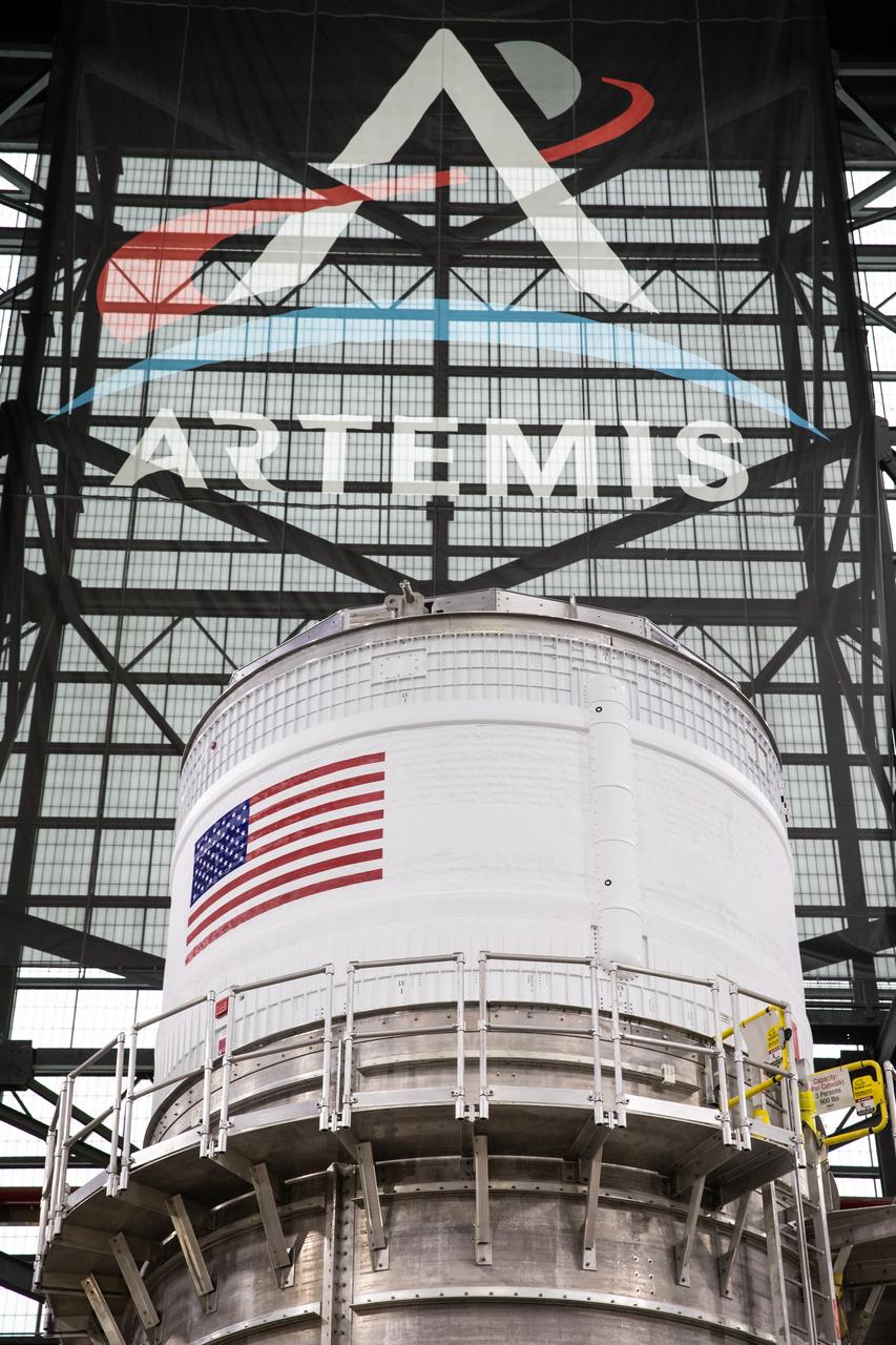
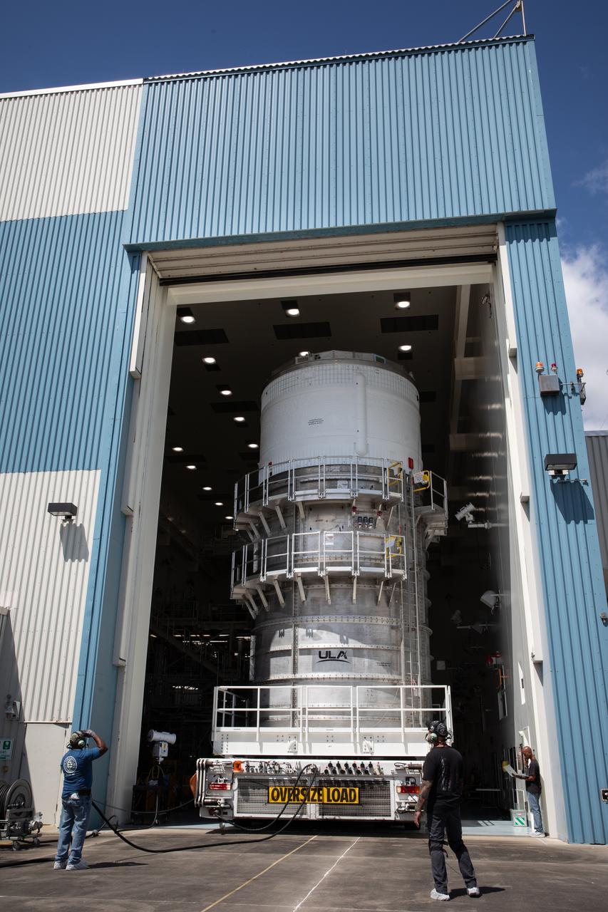
The upper stage for NASA’s Artemis II SLS (Space Launch System) rocket sits in the transfer aisle of the Vehicle Assembly Building at NASA’s Kennedy Space Center in Florida on Wednesday, April 16, 2025, after teams with the agency’s Exploration Ground Systems Program transported the four-story propulsion system from the spaceport’s Multi-Payload Processing Facility (MPPF). Technicians fueled the SLS upper stage, known as the interim cryogenic propulsion stage, with hydrazine for its reaction control system at the MPPF and will now integrate the four-story propulsion system with SLS rocket elements atop mobile launcher 1.
The upper stage for NASA’s Artemis II SLS (Space Launch System) rocket sits in the transfer aisle of the Vehicle Assembly Building at NASA’s Kennedy Space Center in Florida on Wednesday, April 16, 2025, after teams with the agency’s Exploration Ground Systems Program transported the four-story propulsion system from the spaceport’s Multi-Payload Processing Facility (MPPF). Technicians fueled the SLS upper stage, known as the interim cryogenic propulsion stage, with hydrazine for its reaction control system at the MPPF and will now integrate the four-story propulsion system with SLS rocket elements atop mobile launcher 1.

A researcher at the NASA Lewis Research Center with slide ruler poses with models of the earth and a nuclear-propelled rocket. The Nuclear Engine for Rocket Vehicle Applications (NERVA) was a joint NASA and Atomic Energy Commission (AEC) endeavor to develop a nuclear-powered rocket for both long-range missions to Mars and as a possible upper-stage for the Apollo Program. The early portion of the program consisted of basic reactor and fuel system research. This was followed by a series of Kiwi reactors built to test nuclear rocket principles in a non-flying nuclear engine. The next phase, NERVA, would create an entire flyable engine. The AEC was responsible for designing the nuclear reactor and overall engine. NASA Lewis was responsible for developing the liquid-hydrogen fuel system. The nuclear rocket model in this photograph includes a reactor at the far right with a hydrogen propellant tank and large radiator below. The payload or crew would be at the far left, distanced from the reactor.
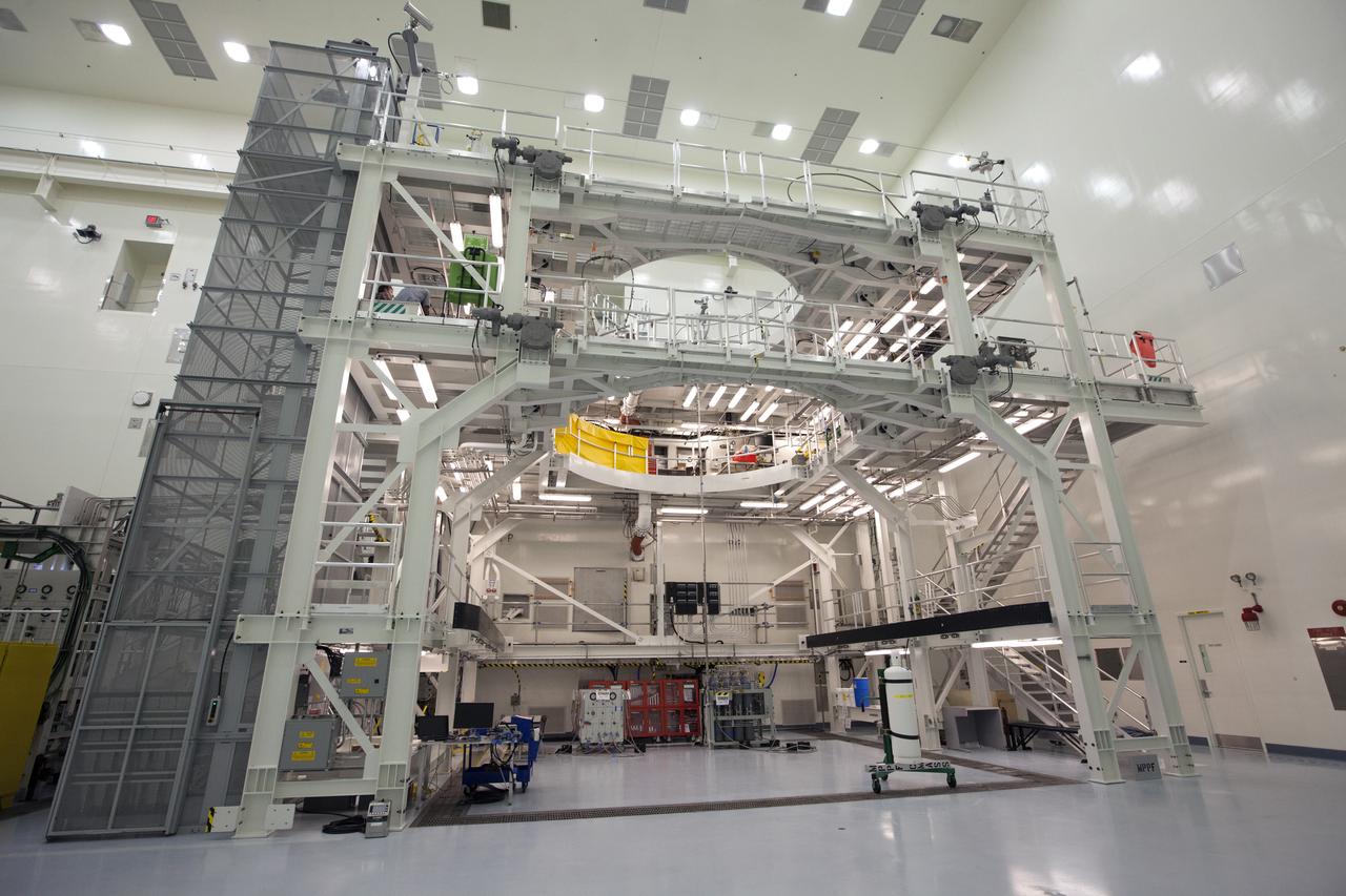
Engineers and technicians completed verification and validation testing of several pneumatic systems inside and outside the Multi-Payload Processing Facility (MPPF) at NASA's Kennedy Space Center in Florida. In view is the service platform for Orion spacecraft processing. The MPPF will be used for offline processing and fueling of the Orion spacecraft and service module stack before launch. Orion also will be de-serviced in the MPPF after a mission. The Ground Systems Development and Operations Program (GSDO) is overseeing upgrades to the facility. The Engineering Directorate led the recent pneumatic tests.
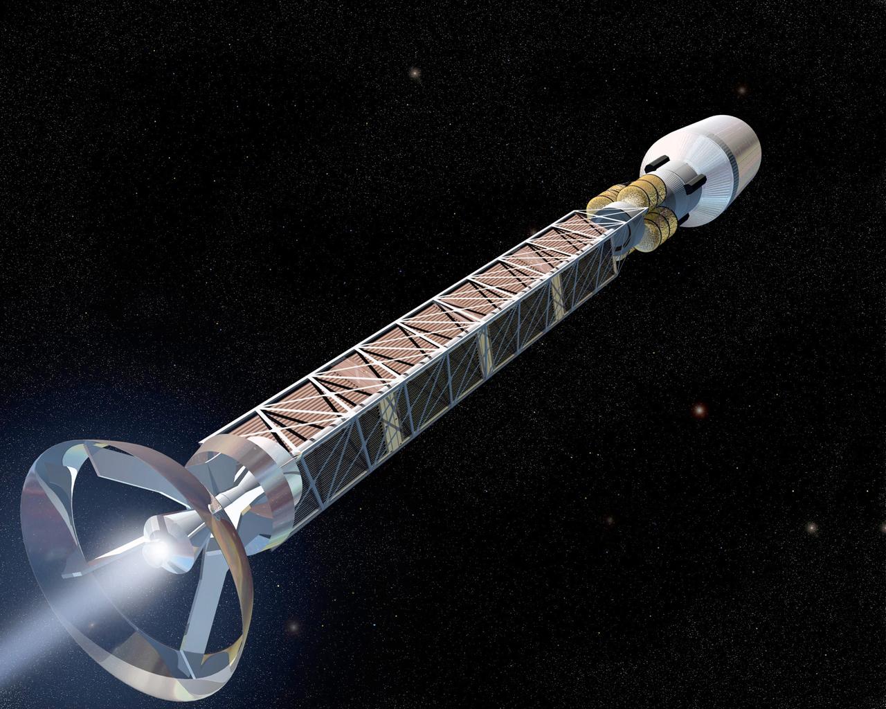
This is an artist's rendition of an antimatter propulsion system. Matter - antimatter arnihilation offers the highest possible physical energy density of any known reaction substance. It is about 10 billion times more powerful than that of chemical engergy such as hydrogen and oxygen combustion. Antimatter would be the perfect rocket fuel, but the problem is that the basic component of antimatter, antiprotons, doesn't exist in nature and has to manufactured. The process of antimatter development is on-going and making some strides, but production of this as a propulsion system is far into the future.
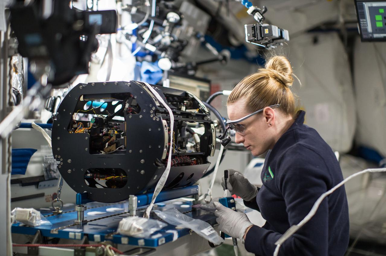
iss049e003808 (9/15/2016) --- NASA astronaut Kate Rubins is photographed replacing two Multi-user Droplet Combustion Apparatus (MDCA) Igniter Tips as part of the Combustion Integration Rack (CIR) Igniter Replacement operations. The CIR is used to perform combustion experiments in microgravity. The CIR can be reconfigured easily on orbit to accommodate a variety of combustion experiments. It consists of an optics bench, a combustion chamber, a fuel and oxidizer management system, environmental management systems, and interfaces for science diagnostics and experiment specific equipment.
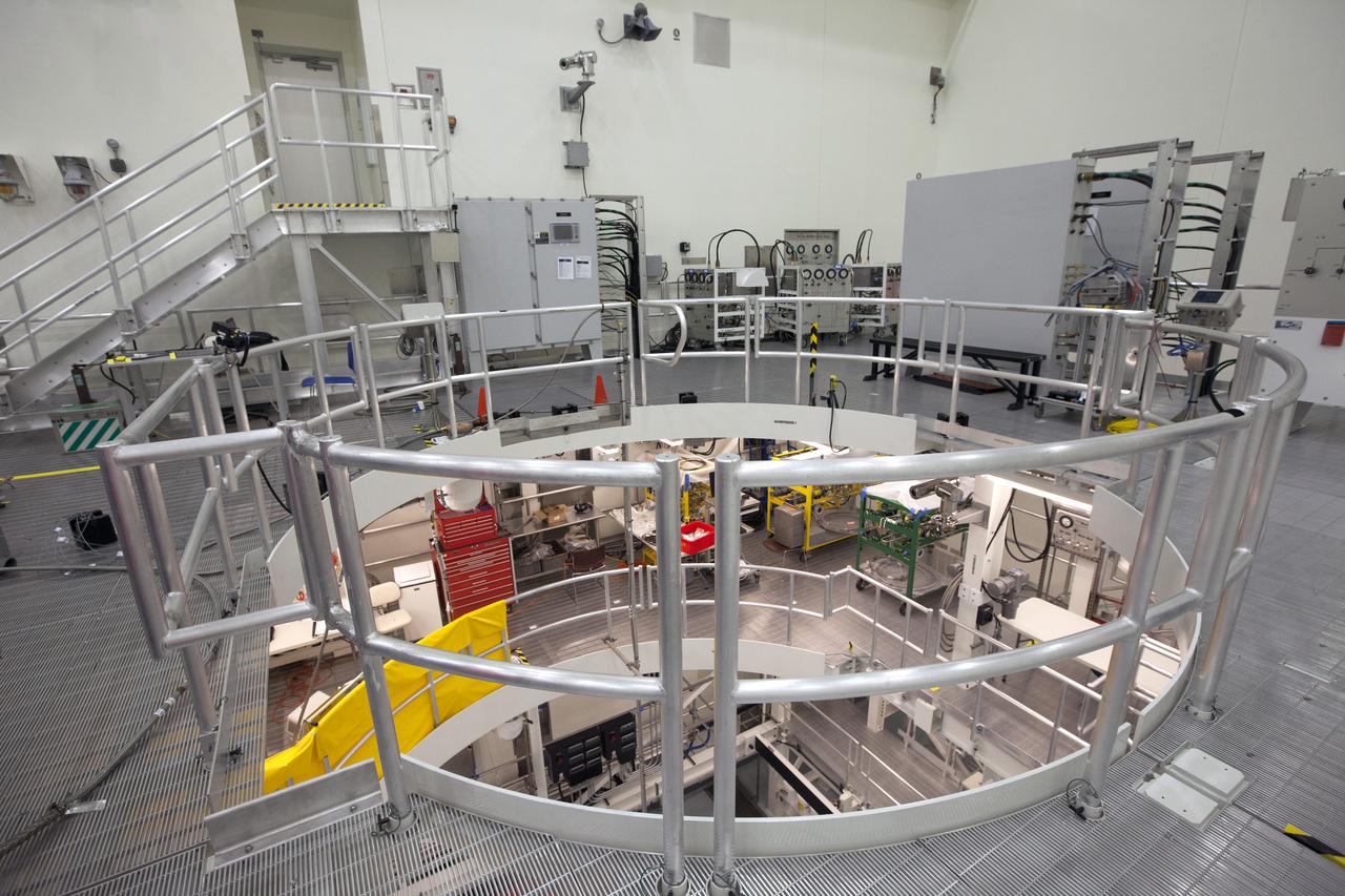
Engineers and technicians completed verification and validation testing of several pneumatic systems inside and outside the Multi-Payload Processing Facility (MPPF) at NASA's Kennedy Space Center in Florida. In view is the top level of the service platform for Orion spacecraft processing. The MPPF will be used for offline processing and fueling of the Orion spacecraft and service module stack before launch. Orion also will be de-serviced in the MPPF after a mission. The Ground Systems Development and Operations Program (GSDO) is overseeing upgrades to the facility. The Engineering Directorate led the recent pneumatic tests.
KENNEDY SPACE CENTER, FLA. - The STS-115 mission crew happily heads to the Astrovan for the ride to Launch Pad 39B and another attempt at liftoff. From the left, in the back row are Mission Specialists Heidemarie Stefanyshyn-Piper and Joseph Tanner; in the center row are Mission Specialists Steven MacLean and Daniel Burbank; in the front row leading the way are Pilot Christopher Ferguson and Commander Brent Jett. The launch attempt on Sept. 8 was scrubbed due to an issue with a fuel cut-off sensor system inside the external fuel tank. This is one of several systems that protect the shuttle's main engines by triggering their shutdown if fuel runs unexpectedly low. During the STS-115 mission, Atlantis' astronauts will deliver and install the 17.5-ton, bus-sized P3/P4 integrated truss segment on the station. The girder-like truss includes a set of giant solar arrays, batteries and associated electronics and will provide one-fourth of the total power-generation capability for the completed station. This mission is the 116th space shuttle flight, the 27th flight for orbiter Atlantis, and the 19th U.S. flight to the ISS. STS-115 is scheduled to last 11 days with a planned landing at KSC. Photo credit: NASA/Kim Shiflett
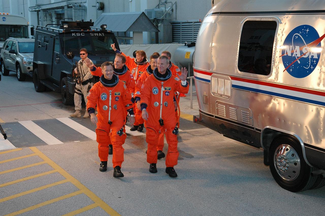
KENNEDY SPACE CENTER, FLA. - The STS-115 mission crew respond to well-wishers as they head to the Astrovan for the ride to Launch Pad 39B. From left are Pilot Christopher Ferguson, Mission Specialists Steven MacLean, Heidemarie Stefanyshyn-Piper, Daniel Burbank and Joseph Tanner (hidden), and Commander Brent Jett. The crew is eager for another attempt at liftoff after the Sept. 8 scrub. The launch attempt on Sept. 8 was scrubbed due to an issue with a fuel cut-off sensor system inside the external fuel tank. This is one of several systems that protect the shuttle's main engines by triggering their shutdown if fuel runs unexpectedly low. During the STS-115 mission, Atlantis' astronauts will deliver and install the 17.5-ton, bus-sized P3/P4 integrated truss segment on the station. The girder-like truss includes a set of giant solar arrays, batteries and associated electronics and will provide one-fourth of the total power-generation capability for the completed station. This mission is the 116th space shuttle flight, the 27th flight for orbiter Atlantis, and the 19th U.S. flight to the ISS. STS-115 is scheduled to last 11 days with a planned landing at KSC. Photo credit: NASA/Kim Shiflett
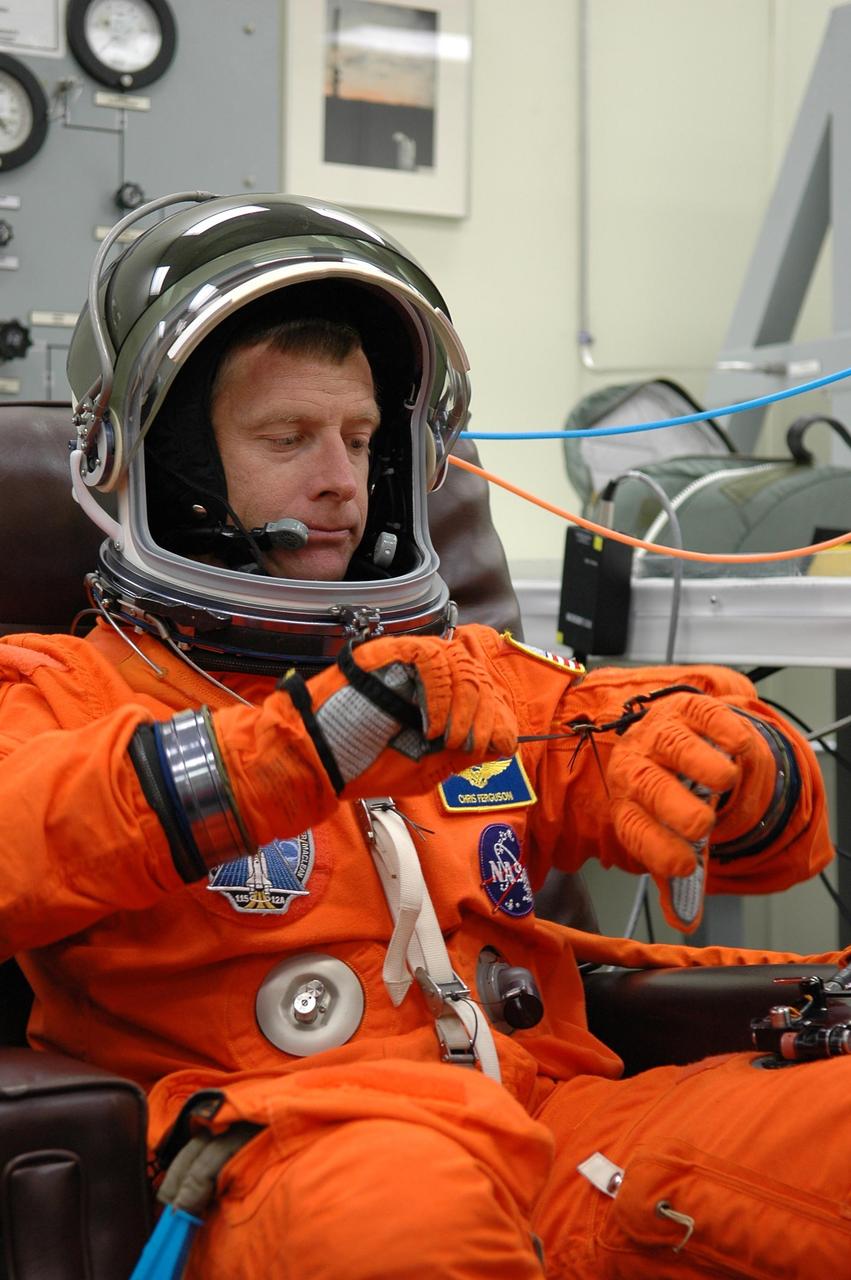
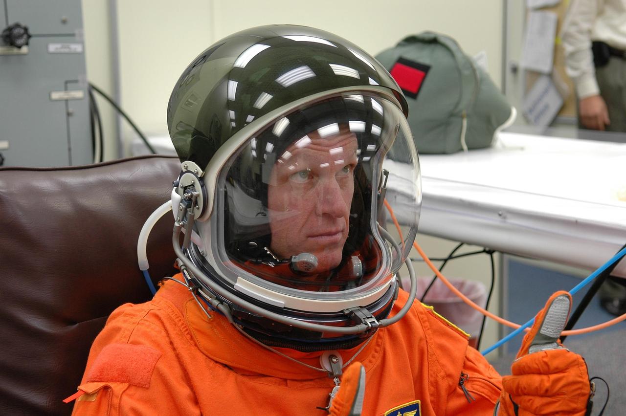
KENNEDY SPACE CENTER, FLA. - In the Operations and Checkout Building at NASA Kennedy Space Center, STS-115 Pilot Christopher Ferguson adjusts his glove during suitup before heading to the launch pad for another attempt at liftoff. The launch attempt on Sept. 8 was scrubbed due to an issue with a fuel cut-off sensor system inside the external fuel tank. This is one of several systems that protect the shuttle's main engines by triggering their shutdown if fuel runs unexpectedly low. During the STS-115 mission, Atlantis' astronauts will deliver and install the 17.5-ton, bus-sized P3/P4 integrated truss segment on the station. The girder-like truss includes a set of giant solar arrays, batteries and associated electronics and will provide one-fourth of the total power-generation capability for the completed station. This mission is the 116th space shuttle flight, the 27th flight for orbiter Atlantis, and the 19th U.S. flight to the ISS. STS-115 is scheduled to last 11 days with a planned landing at KSC. Photo credit: NASA/Kim Shiflett
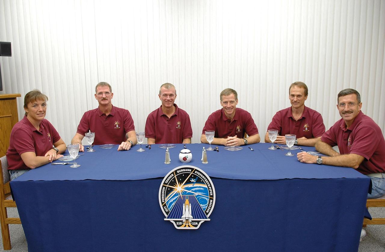
KENNEDY SPACE CENTER, FLA. - After a week's delay of launching due to weather and technical issues, the crew of mission STS-115 have had the traditional breakfast before their third attempt to launch on Space Shuttle Atlantis. Seated left to right are Mission Specialists Heidemarie Stefanyshyn-Piper and Joseph Tanner, Commander Brent Jett, Pilot Christopher Ferguson and Mission Specialists Steven MacLean and Daniel Burbank. MacLean is with the Canadian Space Agency. The launch attempt on Sept. 8 was scrubbed due to an issue with a fuel cut-off sensor system inside the external fuel tank. This is one of several systems that protect the shuttle's main engines by triggering their shutdown if fuel runs unexpectedly low. Following the breakfast, the crew will don their launch suits before heading to Launch Pad 39B. During the STS-115 mission, Atlantis' astronauts will deliver and install the 17.5-ton, bus-sized P3/P4 integrated truss segment on the station. The girder-like truss includes a set of giant solar arrays, batteries and associated electronics and will provide one-fourth of the total power-generation capability for the completed station. This mission is the 116th space shuttle flight, the 27th flight for orbiter Atlantis, and the 19th U.S. flight to the ISS. STS-115 is scheduled to last 11 days with a planned landing at KSC. Photo credit: NASA/Kim Shiflett
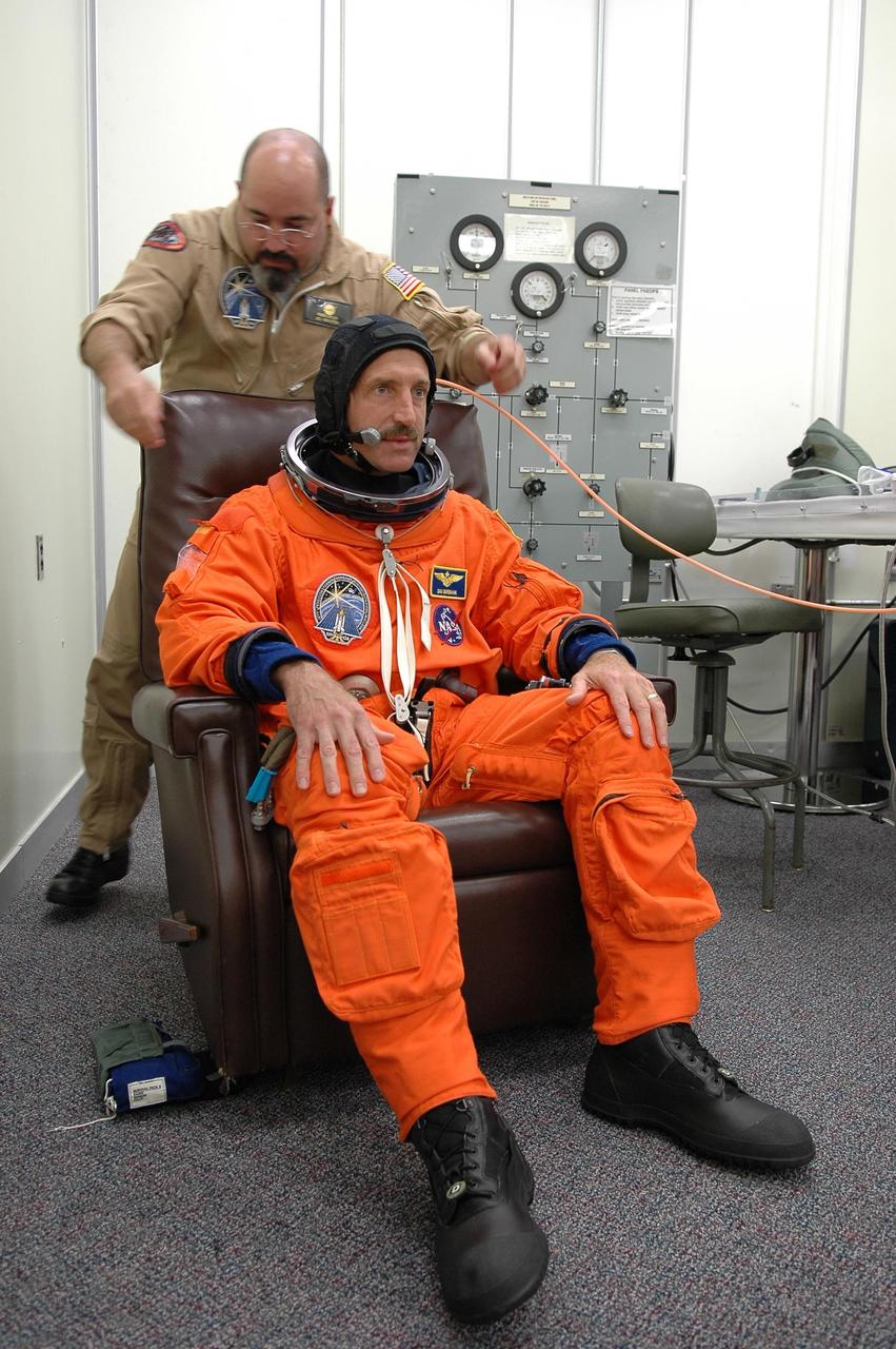
KENNEDY SPACE CENTER, FLA. - In the Operations and Checkout Building at NASA Kennedy Space Center, STS-115 Mission Specialist Daniel Burbank dons his launch and re-entry suit before heading to the launch pad for another attempt at liftoff. The launch attempt on Sept. 8 was scrubbed due to an issue with a fuel cut-off sensor system inside the external fuel tank. This is one of several systems that protect the shuttle's main engines by triggering their shutdown if fuel runs unexpectedly low. During the STS-115 mission, Atlantis' astronauts will deliver and install the 17.5-ton, bus-sized P3/P4 integrated truss segment on the station. The girder-like truss includes a set of giant solar arrays, batteries and associated electronics and will provide one-fourth of the total power-generation capability for the completed station. This mission is the 116th space shuttle flight, the 27th flight for orbiter Atlantis, and the 19th U.S. flight to the ISS. STS-115 is scheduled to last 11 days with a planned landing at KSC. Photo credit: NASA/Kim Shiflett
KENNEDY SPACE CENTER, FLA. - In the Operations and Checkout Building at NASA Kennedy Space Center, STS-115 Mission Commander Brent Jett signals a "go" for another attempt at liftoff. The launch attempt on Sept. 8 was scrubbed due to an issue with a fuel cut-off sensor system inside the external fuel tank. This is one of several systems that protect the shuttle's main engines by triggering their shutdown if fuel runs unexpectedly low. During the STS-115 mission, Atlantis' astronauts will deliver and install the 17.5-ton, bus-sized P3/P4 integrated truss segment on the station. The girder-like truss includes a set of giant solar arrays, batteries and associated electronics and will provide one-fourth of the total power-generation capability for the completed station. This mission is the 116th space shuttle flight, the 27th flight for orbiter Atlantis, and the 19th U.S. flight to the ISS. STS-115 is scheduled to last 11 days with a planned landing at KSC. Photo credit: NASA/Kim Shiflett
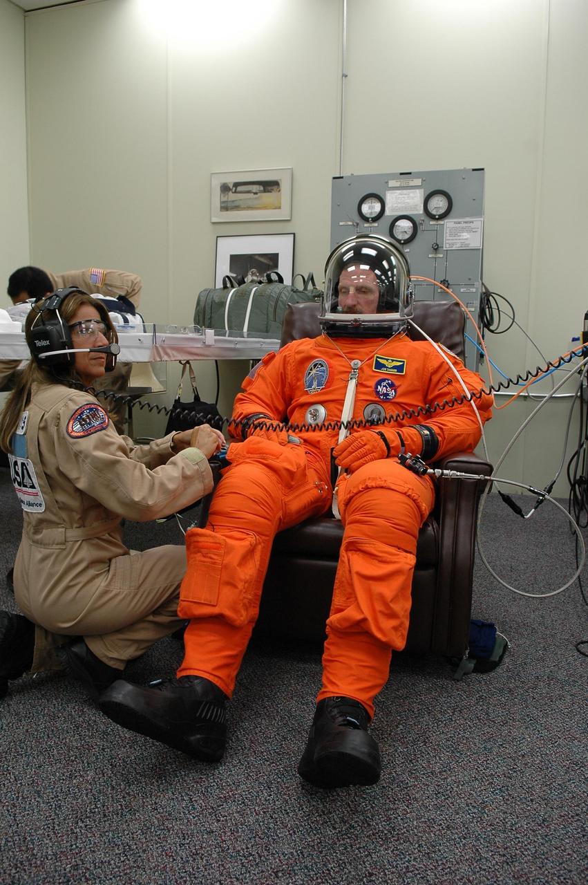
KENNEDY SPACE CENTER, FLA. - In the Operations and Checkout Building at NASA Kennedy Space Center, STS-115 Mission Specialist Joseph Tanner dons his launch and re-entry suit before heading to the launch pad for another attempt at liftoff. The launch attempt on Sept. 8 was scrubbed due to an issue with a fuel cut-off sensor system inside the external fuel tank. This is one of several systems that protect the shuttle's main engines by triggering their shutdown if fuel runs unexpectedly low. Liftoff today is scheduled for 11:15 a.m. EDT. During the STS-115 mission, Atlantis' astronauts will deliver and install the 17.5-ton, bus-sized P3/P4 integrated truss segment on the station. The girder-like truss includes a set of giant solar arrays, batteries and associated electronics and will provide one-fourth of the total power-generation capability for the completed station. This mission is the 116th space shuttle flight, the 27th flight for orbiter Atlantis, and the 19th U.S. flight to the ISS. STS-115 is scheduled to last 11 days with a planned landing at KSC. Photo credit: NASA/Kim Shiflett

KENNEDY SPACE CENTER, FLA. - In the Operations and Checkout Building at NASA Kennedy Space Center, STS-115 Mission Commander Brent Jett finishes suiting up for another attempt at liftoff. The launch attempt on Sept. 8 was scrubbed due to an issue with a fuel cut-off sensor system inside the external fuel tank. This is one of several systems that protect the shuttle's main engines by triggering their shutdown if fuel runs unexpectedly low. During the STS-115 mission, Atlantis' astronauts will deliver and install the 17.5-ton, bus-sized P3/P4 integrated truss segment on the station. The girder-like truss includes a set of giant solar arrays, batteries and associated electronics and will provide one-fourth of the total power-generation capability for the completed station. This mission is the 116th space shuttle flight, the 27th flight for orbiter Atlantis, and the 19th U.S. flight to the ISS. STS-115 is scheduled to last 11 days with a planned landing at KSC. Photo credit: NASA/Kim Shiflett

KENNEDY SPACE CENTER, FLA. - In the Operations and Checkout Building at NASA Kennedy Space Center, STS-115 Pilot Christopher Ferguson finishes suiting up for another attempt at liftoff. The launch attempt on Sept. 8 was scrubbed due to an issue with a fuel cut-off sensor system inside the external fuel tank. This is one of several systems that protect the shuttle's main engines by triggering their shutdown if fuel runs unexpectedly low. During the STS-115 mission, Atlantis' astronauts will deliver and install the 17.5-ton, bus-sized P3/P4 integrated truss segment on the station. The girder-like truss includes a set of giant solar arrays, batteries and associated electronics and will provide one-fourth of the total power-generation capability for the completed station. This mission is the 116th space shuttle flight, the 27th flight for orbiter Atlantis, and the 19th U.S. flight to the ISS. STS-115 is scheduled to last 11 days with a planned landing at KSC. Photo credit: NASA/Kim Shiflett

KENNEDY SPACE CENTER, FLA. - In the Operations and Checkout Building at NASA Kennedy Space Center, STS-115 Mission Specialist Steven MacLean dons his helmet to complete suiting up for another attempt at liftoff. MacLean is with the Canadian Space Agency. The launch attempt on Sept. 8 was scrubbed due to an issue with a fuel cut-off sensor system inside the external fuel tank. This is one of several systems that protect the shuttle's main engines by triggering their shutdown if fuel runs unexpectedly low. During the STS-115 mission, Atlantis' astronauts will deliver and install the 17.5-ton, bus-sized P3/P4 integrated truss segment on the station. The girder-like truss includes a set of giant solar arrays, batteries and associated electronics and will provide one-fourth of the total power-generation capability for the completed station. This mission is the 116th space shuttle flight, the 27th flight for orbiter Atlantis, and the 19th U.S. flight to the ISS. STS-115 is scheduled to last 11 days with a planned landing at KSC. Photo credit: NASA/Kim Shiflett
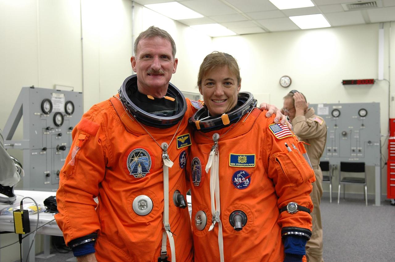
KENNEDY SPACE CENTER, FLA. - In the Operations and Checkout Building at NASA Kennedy Space Center, STS-115 Mission Specialists Joseph Tanner and Heidemarie Stefanyshyn-Piper pose while suiting up for the ride to Launch Pad 39B and another attempt at liftoff. The launch attempt on Sept. 8 was scrubbed due to an issue with a fuel cut-off sensor system inside the external fuel tank. This is one of several systems that protect the shuttle's main engines by triggering their shutdown if fuel runs unexpectedly low. During the STS-115 mission, Atlantis' astronauts will deliver and install the 17.5-ton, bus-sized P3/P4 integrated truss segment on the station. The girder-like truss includes a set of giant solar arrays, batteries and associated electronics and will provide one-fourth of the total power-generation capability for the completed station. This mission is the 116th space shuttle flight, the 27th flight for orbiter Atlantis, and the 19th U.S. flight to the ISS. STS-115 is scheduled to last 11 days with a planned landing at KSC. Photo credit: NASA/Kim Shiflett
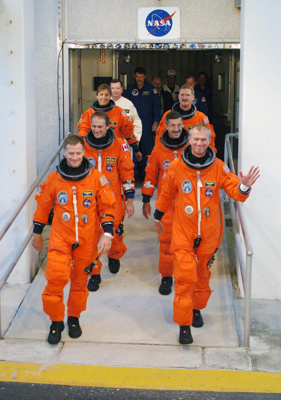
KENNEDY SPACE CENTER, FLA. - After suiting up, the STS-115 mission crew exits the Operations and Checkout Building to board the Astrovan to Launch Pad 39B. On the left, front to back, are Pilot Christopher Ferguson and Mission Specialists Steven MacLean and Heidemarie Stefanyshyn-Piper. On the right, front to back, are Commander Brent Jett and Mission Specialists Daniel Burbank and Joseph Tanner. The launch attempt on Sept. 8 was scrubbed due to an issue with a fuel cut-off sensor system inside the external fuel tank. This is one of several systems that protect the shuttle's main engines by triggering their shutdown if fuel runs unexpectedly low. During the STS-115 mission, Atlantis' astronauts will deliver and install the 17.5-ton, bus-sized P3/P4 integrated truss segment on the station. The girder-like truss includes a set of giant solar arrays, batteries and associated electronics and will provide one-fourth of the total power-generation capability for the completed station. This mission is the 116th space shuttle flight, the 27th flight for orbiter Atlantis, and the 19th U.S. flight to the ISS. STS-115 is scheduled to last 11 days with a planned landing at KSC. Photo credit: NASA/Kim Shiflett
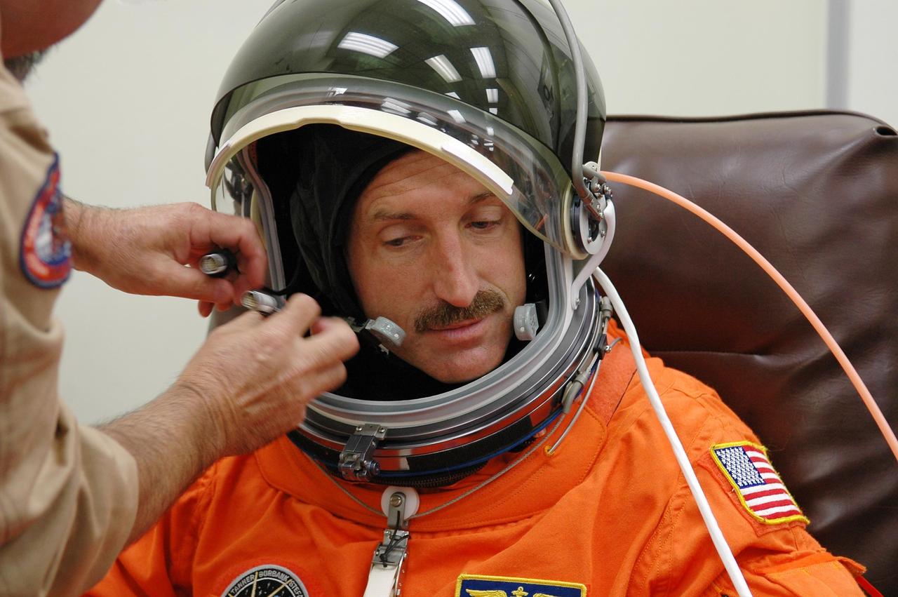
KENNEDY SPACE CENTER, FLA. - In the Operations and Checkout Building at NASA Kennedy Space Center, STS-115 Mission Specialist Daniel Burbank gets a final adjustment on his helmet before heading to the launch pad for another attempt at liftoff. The launch attempt on Sept. 8 was scrubbed due to an issue with a fuel cut-off sensor system inside the external fuel tank. This is one of several systems that protect the shuttle's main engines by triggering their shutdown if fuel runs unexpectedly low. During the STS-115 mission, Atlantis' astronauts will deliver and install the 17.5-ton, bus-sized P3/P4 integrated truss segment on the station. The girder-like truss includes a set of giant solar arrays, batteries and associated electronics and will provide one-fourth of the total power-generation capability for the completed station. This mission is the 116th space shuttle flight, the 27th flight for orbiter Atlantis, and the 19th U.S. flight to the ISS. STS-115 is scheduled to last 11 days with a planned landing at KSC. Photo credit: NASA/Kim Shiflett
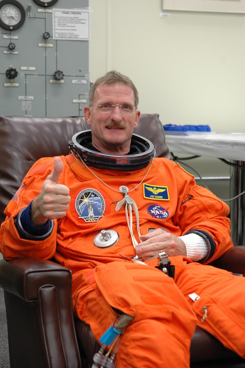
KENNEDY SPACE CENTER, FLA. - During suitup in the Operations and Checkout Building at NASA Kennedy Space Center, STS-115 Mission Specialist Joseph Tanner signals a "go" for another attempt at liftoff. The launch attempt on Sept. 8 was scrubbed due to an issue with a fuel cut-off sensor system inside the external fuel tank. This is one of several systems that protect the shuttle's main engines by triggering their shutdown if fuel runs unexpectedly low. During the STS-115 mission, Atlantis' astronauts will deliver and install the 17.5-ton, bus-sized P3/P4 integrated truss segment on the station. The girder-like truss includes a set of giant solar arrays, batteries and associated electronics and will provide one-fourth of the total power-generation capability for the completed station. This mission is the 116th space shuttle flight, the 27th flight for orbiter Atlantis, and the 19th U.S. flight to the ISS. STS-115 is scheduled to last 11 days with a planned landing at KSC. Photo credit: NASA/Kim Shiflett

KENNEDY SPACE CENTER, FLA. - In the Operations and Checkout Building at NASA Kennedy Space Center, STS-115 Mission Specialist Steven MacLean signals "go" for another attempt at liftoff. MacLean is with the Canadian Space Agency. The launch attempt on Sept. 8 was scrubbed due to an issue with a fuel cut-off sensor system inside the external fuel tank. This is one of several systems that protect the shuttle's main engines by triggering their shutdown if fuel runs unexpectedly low. During the STS-115 mission, Atlantis' astronauts will deliver and install the 17.5-ton, bus-sized P3/P4 integrated truss segment on the station. The girder-like truss includes a set of giant solar arrays, batteries and associated electronics and will provide one-fourth of the total power-generation capability for the completed station. This mission is the 116th space shuttle flight, the 27th flight for orbiter Atlantis, and the 19th U.S. flight to the ISS. STS-115 is scheduled to last 11 days with a planned landing at KSC. Photo credit: NASA/Kim Shiflett
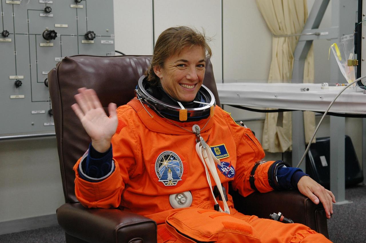
KENNEDY SPACE CENTER, FLA. - In the Operations and Checkout Building at NASA Kennedy Space Center, STS-115 Mission Specialist Heidemarie Stefanyshyn-Piper is eager for another attempt at liftoff. The launch attempt on Sept. 8 was scrubbed due to an issue with a fuel cut-off sensor system inside the external fuel tank. This is one of several systems that protect the shuttle's main engines by triggering their shutdown if fuel runs unexpectedly low. During the STS-115 mission, Atlantis' astronauts will deliver and install the 17.5-ton, bus-sized P3/P4 integrated truss segment on the station. The girder-like truss includes a set of giant solar arrays, batteries and associated electronics and will provide one-fourth of the total power-generation capability for the completed station. This mission is the 116th space shuttle flight, the 27th flight for orbiter Atlantis, and the 19th U.S. flight to the ISS. STS-115 is scheduled to last 11 days with a planned landing at KSC. Photo credit: NASA/Kim Shiflett

KENNEDY SPACE CENTER, FLA. - In the Operations and Checkout Building at NASA Kennedy Space Center, STS-115 Mission Specialist Heidemarie Stefanyshyn-Piper is donning her launch and re-entry suit before heading to the launch pad for another attempt at liftoff. The launch attempt on Sept. 8 was scrubbed due to an issue with a fuel cut-off sensor system inside the external fuel tank. This is one of several systems that protect the shuttle's main engines by triggering their shutdown if fuel runs unexpectedly low. During the STS-115 mission, Atlantis' astronauts will deliver and install the 17.5-ton, bus-sized P3/P4 integrated truss segment on the station. The girder-like truss includes a set of giant solar arrays, batteries and associated electronics and will provide one-fourth of the total power-generation capability for the completed station. This mission is the 116th space shuttle flight, the 27th flight for orbiter Atlantis, and the 19th U.S. flight to the ISS. STS-115 is scheduled to last 11 days with a planned landing at KSC. Photo credit: NASA/Kim Shiflett
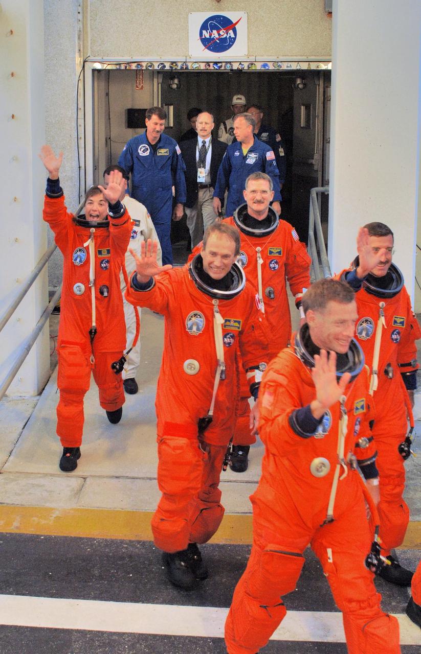
KENNEDY SPACE CENTER, FLA. - After suiting up, the STS-115 mission crew enthusiastically greet the onlookers as they head to the Astrovan for the ride to Launch Pad 39B. From left are Mission Specialist Heidemarie Stefanyshyn-Piper, Steven MacLean, Joseph Tanner, Pilot Christopher Ferguson and Daniel Burbank. Not seen is Commander Brent Jett. The crew is eager for another attempt at liftoff after the Sept. 8 scrub. The launch attempt on Sept. 8 was scrubbed due to an issue with a fuel cut-off sensor system inside the external fuel tank. This is one of several systems that protect the shuttle's main engines by triggering their shutdown if fuel runs unexpectedly low. During the STS-115 mission, Atlantis' astronauts will deliver and install the 17.5-ton, bus-sized P3/P4 integrated truss segment on the station. The girder-like truss includes a set of giant solar arrays, batteries and associated electronics and will provide one-fourth of the total power-generation capability for the completed station. This mission is the 116th space shuttle flight, the 27th flight for orbiter Atlantis, and the 19th U.S. flight to the ISS. STS-115 is scheduled to last 11 days with a planned landing at KSC. Photo credit: NASA/Kim Shiflett

The first research assignment specifically created for the National Advisory Committee for Aeronautics’ (NACA) new Aircraft Engine Research Laboratory was the integration of a supercharger into the Allison V–1710 engine. The military was relying on the liquid-cooled V–1710 to power several types of World War II fighter aircraft and wanted to improve the engine's speed and altitude performance. Superchargers forced additional airflow into the combustion chamber, which increased the engine’s performance resulting in greater altitudes and speeds. They also generated excess heat that affected the engine cylinders, oil, and fuel. In 1943 the military tasked the new Aircraft Engine Research Laboratory to integrate the supercharger, improve the cooling system, and remedy associated engine knock. Three Allison engines were provided to the laboratory’s research divisions. One group was tasked with improving the supercharger performance, another analyzed the effect of the increased heat on knock in the fuel, one was responsible for improving the cooling system, and another would install the new components on the engine with minimal drag penalties. The modified engines were installed on this 2000-horsepower dynamotor stand in a test cell within the Engine Research Building. The researchers could run the engine at different temperatures, fuel-air ratios, and speeds. When the modifications were complete, the improved V–1710 was flight tested on a P–63A Kingcobra loaned to the NACA for this project.
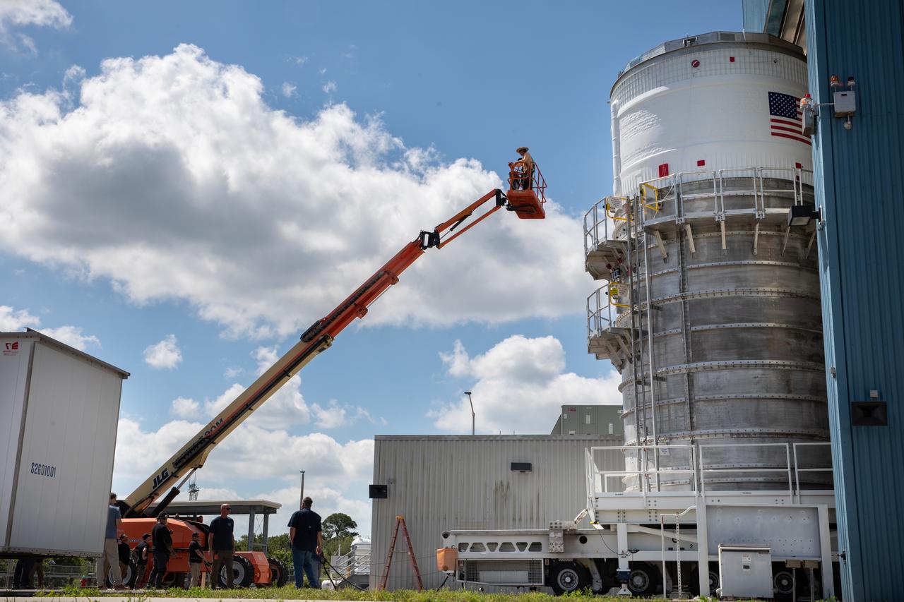
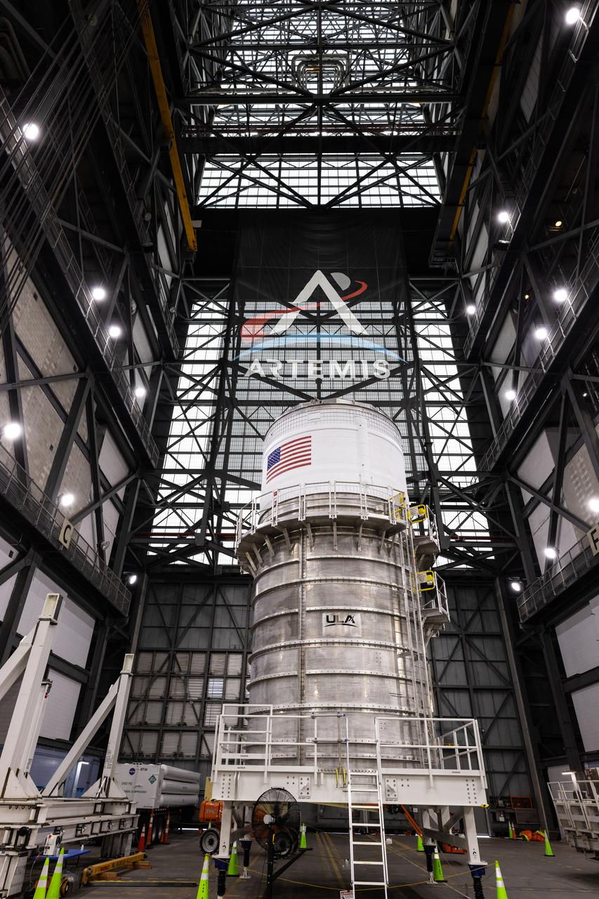
Teams with NASA’s Exploration Ground Systems Program transport the upper stage for the agency’s Artemis II SLS (Space Launch System) rocket from the Multi-Payload Processing Facility (MPPF) at NASA’s Kennedy Space Center in Florida to the spaceport’s Vehicle Assembly Building on Wednesday, April 16, 2025. Technicians fueled the SLS upper stage, known as the interim cryogenic propulsion stage, with hydrazine for its reaction control system at the MPPF and will now integrate the four-story propulsion system with SLS rocket elements atop mobile launcher 1.
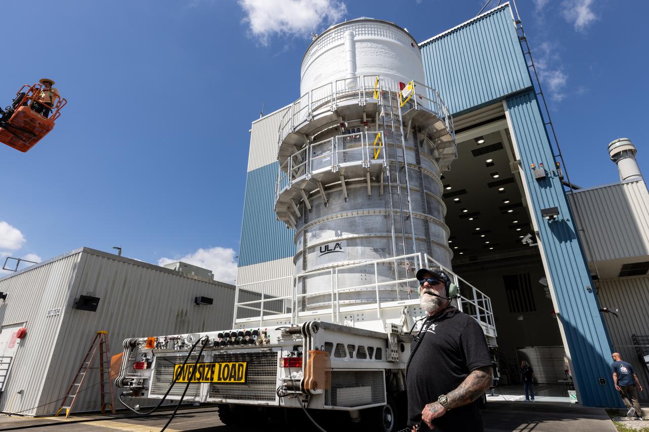
Teams with NASA’s Exploration Ground Systems Program transport the upper stage for the agency’s Artemis II SLS (Space Launch System) rocket from the Multi-Payload Processing Facility (MPPF) at NASA’s Kennedy Space Center in Florida to the spaceport’s Vehicle Assembly Building on Wednesday, April 16, 2025. Technicians fueled the SLS upper stage, known as the interim cryogenic propulsion stage, with hydrazine for its reaction control system at the MPPF and will now integrate the four-story propulsion system with SLS rocket elements atop mobile launcher 1.

Teams with NASA’s Exploration Ground Systems Program transport the upper stage for the agency’s Artemis II SLS (Space Launch System) rocket from the Multi-Payload Processing Facility (MPPF) at NASA’s Kennedy Space Center in Florida to the spaceport’s Vehicle Assembly Building on Wednesday, April 16, 2025. Technicians fueled the SLS upper stage, known as the interim cryogenic propulsion stage, with hydrazine for its reaction control system at the MPPF and will now integrate the four-story propulsion system with SLS rocket elements atop mobile launcher 1.
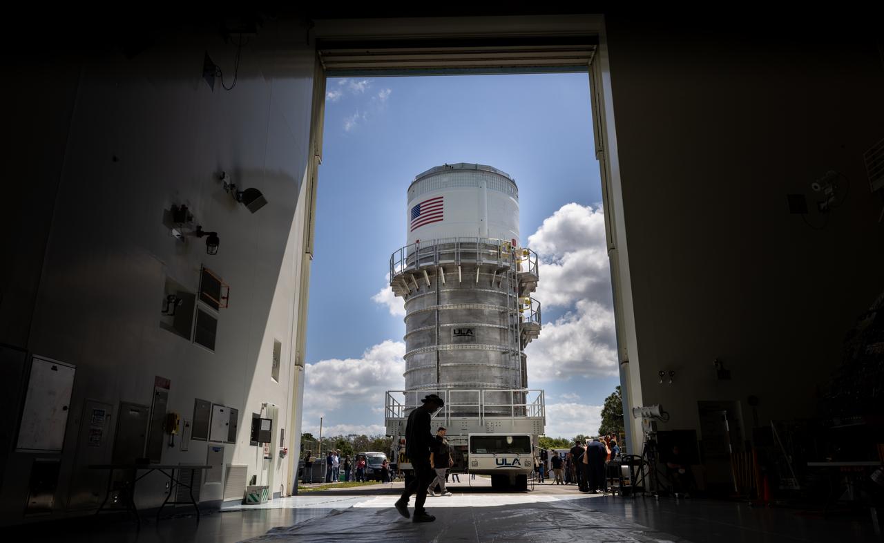
Teams with NASA’s Exploration Ground Systems Program transport the upper stage for the agency’s Artemis II SLS (Space Launch System) rocket from the Multi-Payload Processing Facility (MPPF) at NASA’s Kennedy Space Center in Florida to the spaceport’s Vehicle Assembly Building on Wednesday, April 16, 2025. Technicians fueled the SLS upper stage, known as the interim cryogenic propulsion stage, with hydrazine for its reaction control system at the MPPF and will now integrate the four-story propulsion system with SLS rocket elements atop mobile launcher 1.
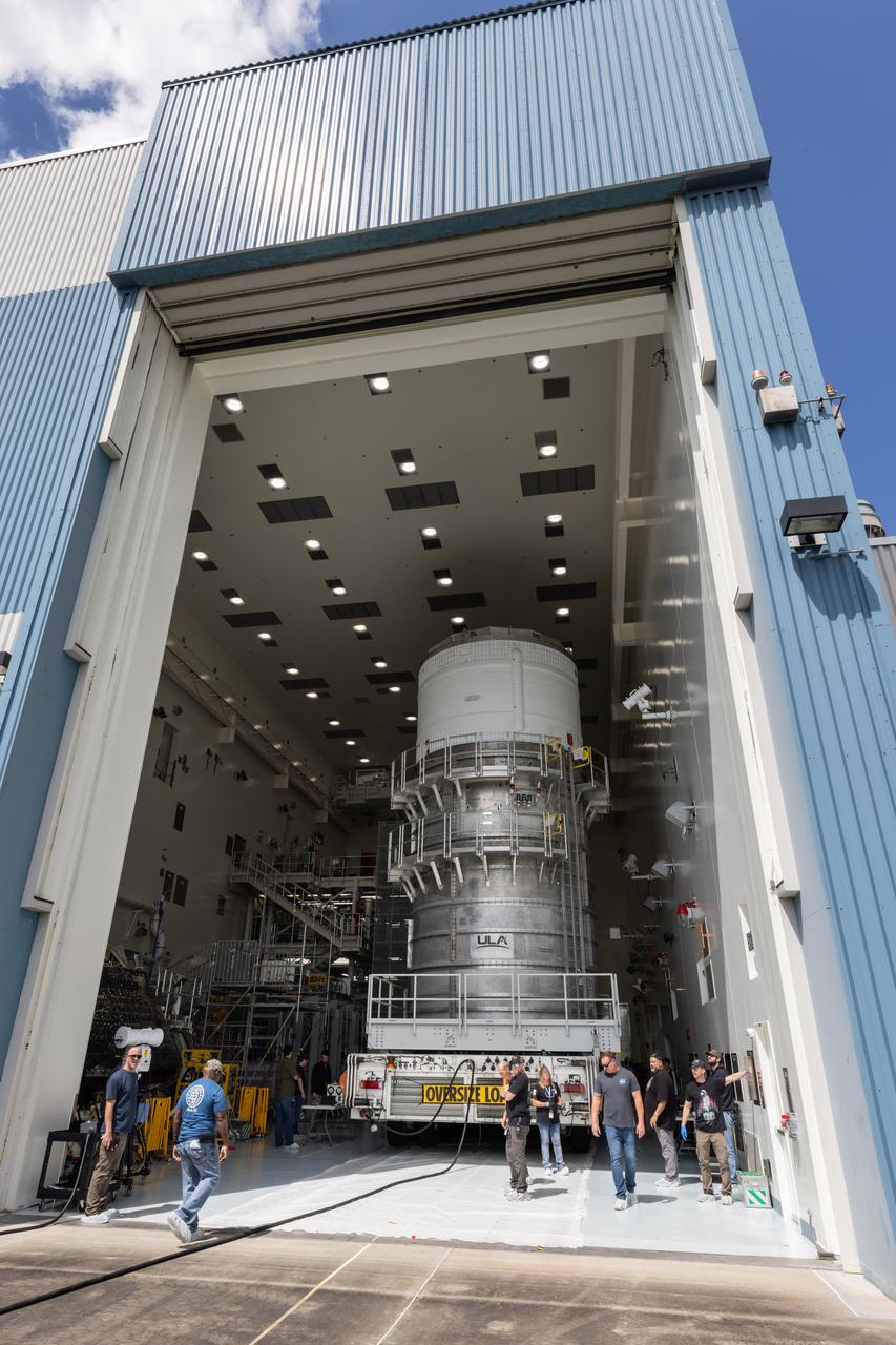
Teams with NASA’s Exploration Ground Systems Program transport the upper stage for the agency’s Artemis II SLS (Space Launch System) rocket from the Multi-Payload Processing Facility (MPPF) at NASA’s Kennedy Space Center in Florida to the spaceport’s Vehicle Assembly Building on Wednesday, April 16, 2025. Technicians fueled the SLS upper stage, known as the interim cryogenic propulsion stage, with hydrazine for its reaction control system at the MPPF and will now integrate the four-story propulsion system with SLS rocket elements atop mobile launcher 1.
Teams with NASA’s Exploration Ground Systems Program transport the upper stage for the agency’s Artemis II SLS (Space Launch System) rocket from the Multi-Payload Processing Facility (MPPF) at NASA’s Kennedy Space Center in Florida to the spaceport’s Vehicle Assembly Building on Wednesday, April 16, 2025. Technicians fueled the SLS upper stage, known as the interim cryogenic propulsion stage, with hydrazine for its reaction control system at the MPPF and will now integrate the four-story propulsion system with SLS rocket elements atop mobile launcher 1.
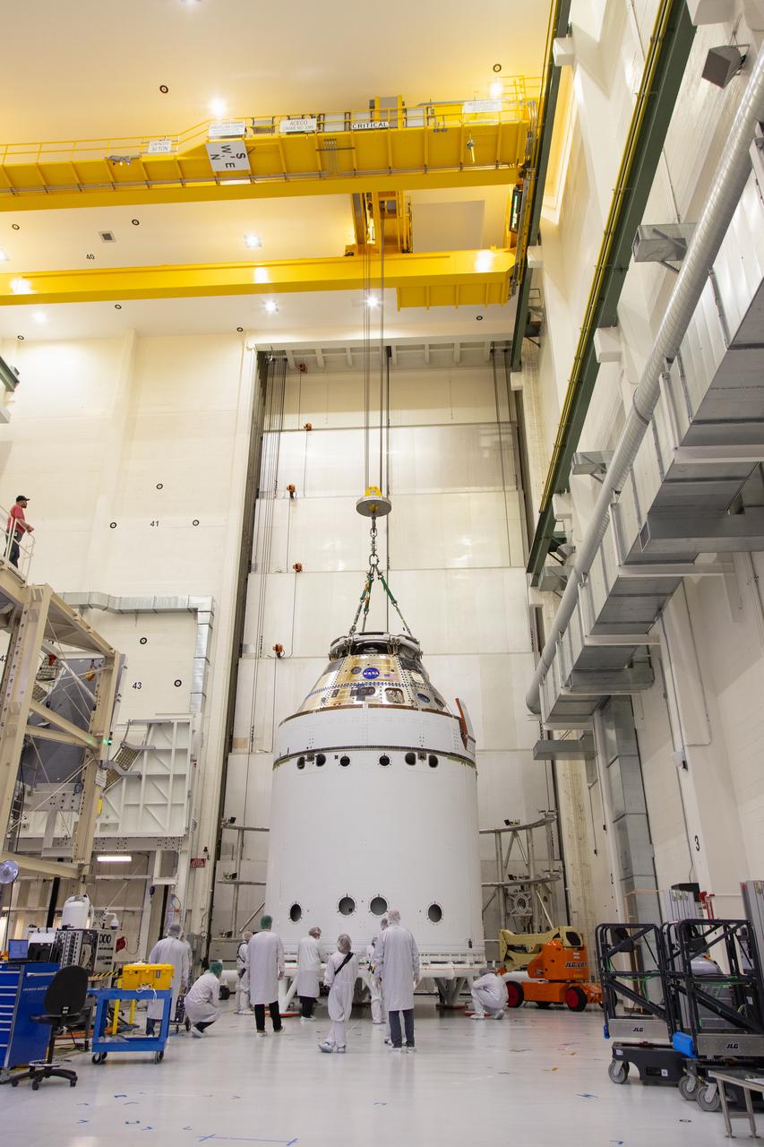
A crane returns NASA’s Artemis II Orion spacecraft to the Final Assembly and System Testing (FAST) cell inside the Neil A. Armstrong Operations and Checkout Building at NASA’s Kennedy Space Center in Florida on Friday, March 21, 2025, following installation of four solar array winds and adapter jettison fairings. Once complete, the Orion spacecraft will be transported to other facilities for fueling and integration with its launch abort system before arriving at the Vehicle Assembly Building where it will be stacked atop the SLS (Space Launch System) by NASA’s Exploration Ground System team at the Vehicle Assembly Building in preparations for Artemis II launch operations.