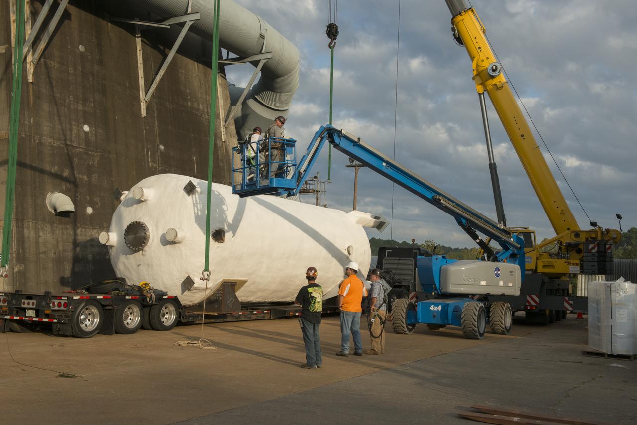
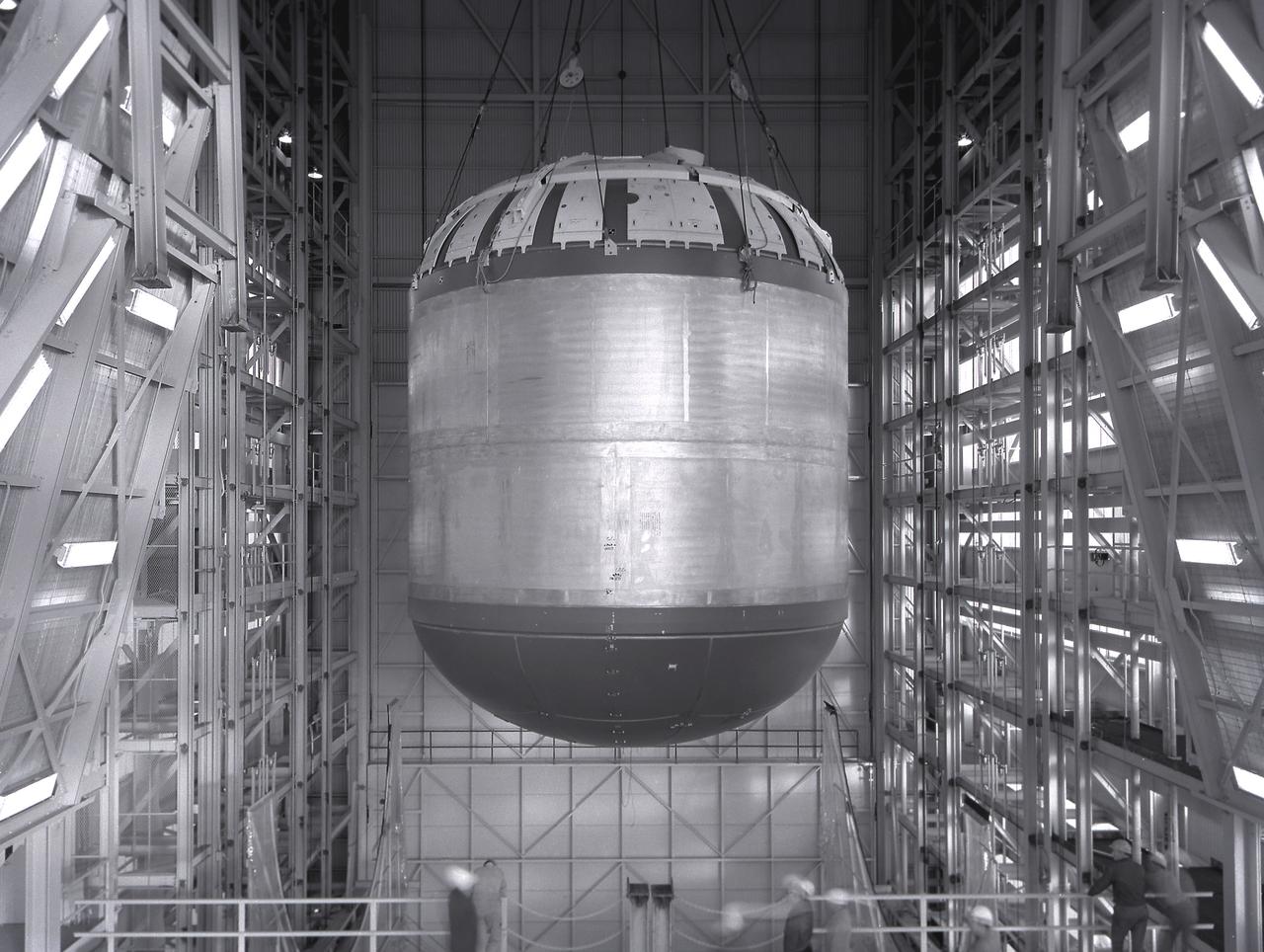
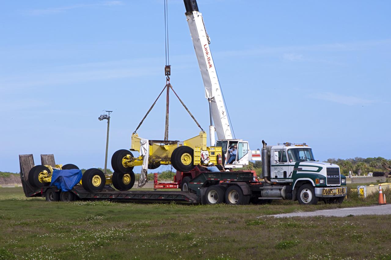
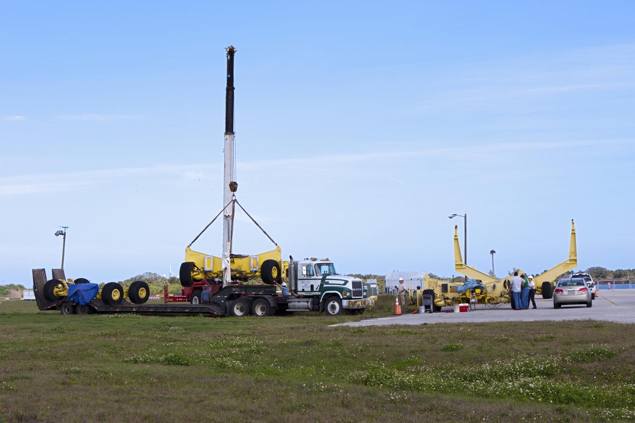
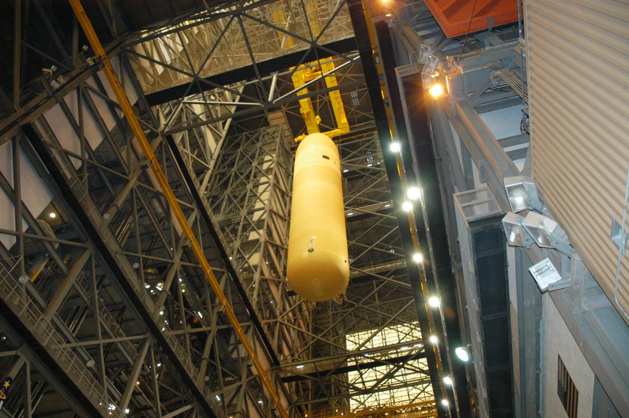
BOEING HIGH CAPACITY FUEL TANK BEING READIED FOR PLACEMENT ON WEST TEST AREA TEST STAND IN ANTICIPATION OF FURTHER TESTING.
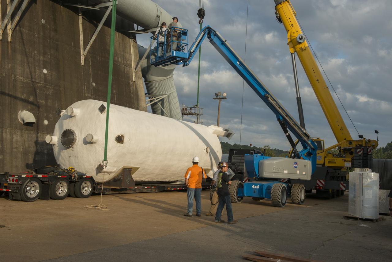
BOEING HIGH CAPACITY FUEL TANK BEING READIED FOR PLACEMENT ON WEST TEST AREA TEST STAND IN ANTICIPATION OF FURTHER TESTING.
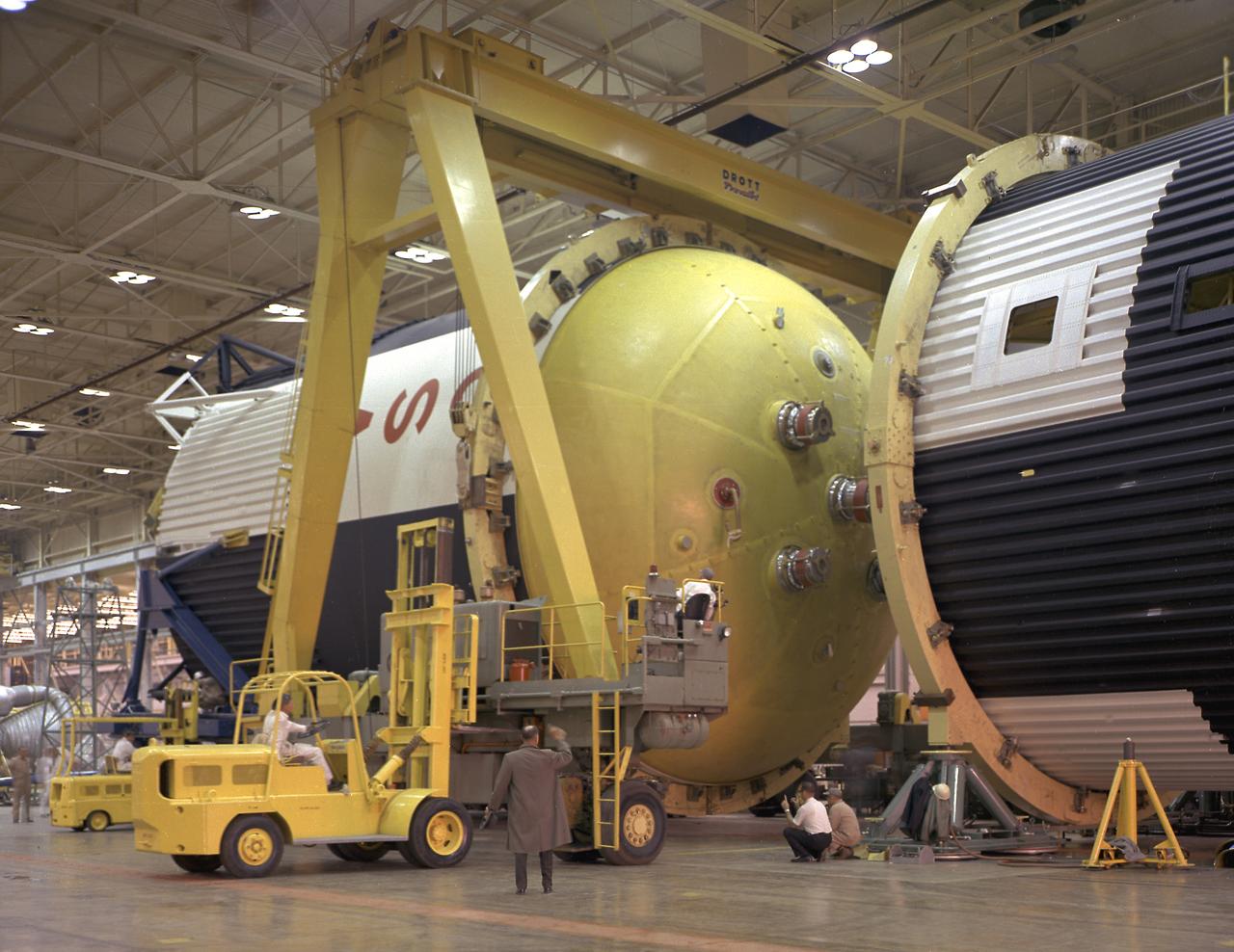
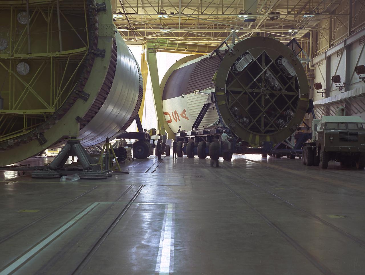
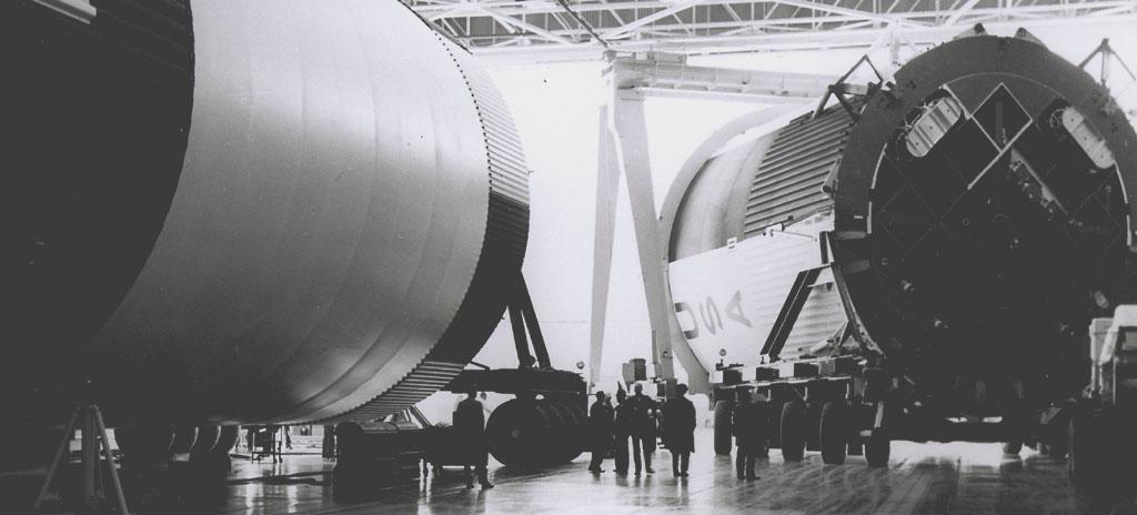
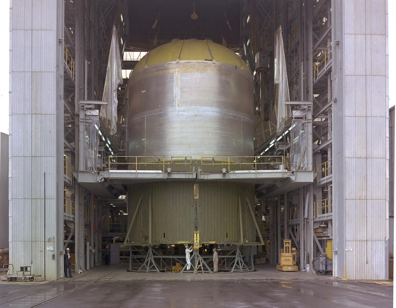
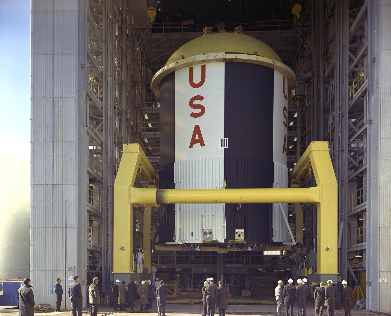
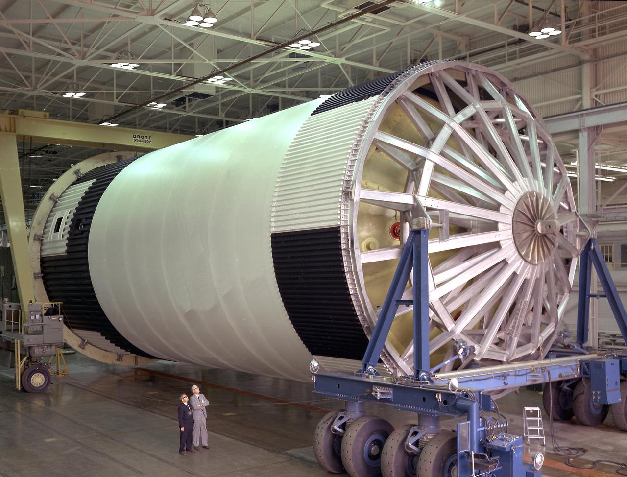
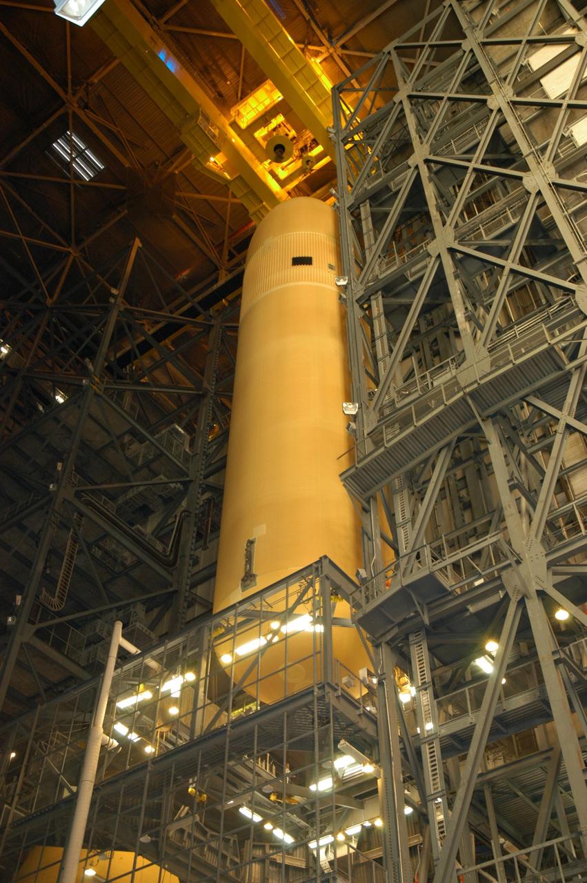
This photograph shows how the fuel tank assembly and the liquid oxygen tank for the Saturn V S-IC (first) stage are placed side by side prior to commencement of the mating of the two stages in the Marshall Space Flight Center, building 4705. The fuel tank carried kerosene as its fuel. The S-IC stage used five F-1 engines, that used kerosene and liquid oxygen as propellant and each engine provided 1,500,000 pounds of thrust. This stage lifted the entire vehicle and Apollo spacecraft from the launch pad.
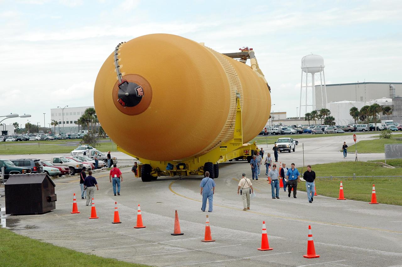
This photograph shows the fuel tank assembly for the Saturn V S-IC (first) stage being transported to the Marshall Space Flight Center, building 4705 for mating to the liquid oxygen (LOX) tank. The fuel tank carried kerosene (RP-1) as its fuel. The S-IC stage used five F-1 engines, that used kerosene and liquid oxygen as propellant and each engine provided 1,500,000 pounds of thrust. This stage lifted the entire vehicle and Apollo spacecraft from the launch pad.
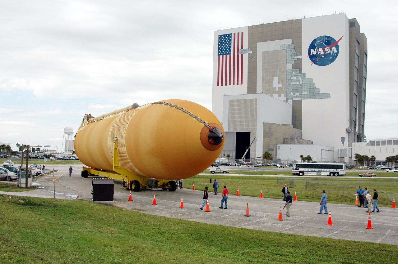
The fuel tank assembly for the Saturn V S-IC (first) stage arrived at the Marshall Space Flight Center, building 4707, for mating to the liquid oxygen tank. The fuel tank carried kerosene as its fuel. The S-IC stage used five F-1 engines, that used kerosene and liquid oxygen as propellant and each engine provided 1,500,000 pounds of thrust. This stage lifted the entire vehicle and Apollo spacecraft from the launch pad.
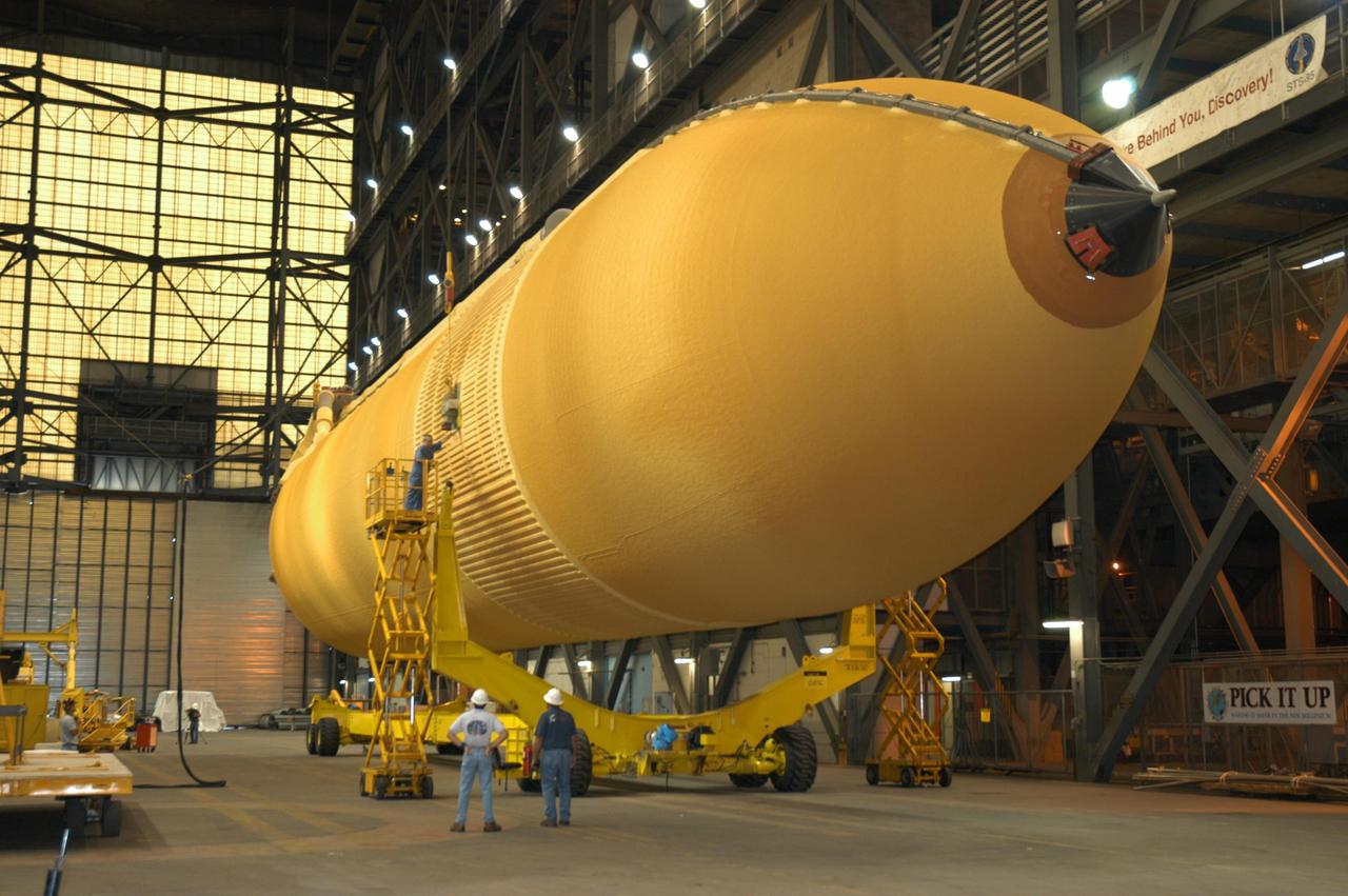
The fuel tank assembly of the Saturn V S-IC (first) stage is readied to be mated to the liquid oxygen tank at the Marshall Space Flight Center. The fuel tank carried kerosene as its fuel. The S-IC stage utilized five F-1 engines that used kerosene and liquid oxygen as propellant. Each engine provided 1,500,000 pounds of thrust. This stage lifted the entire vehicle and Apollo spacecraft from the launch pad.
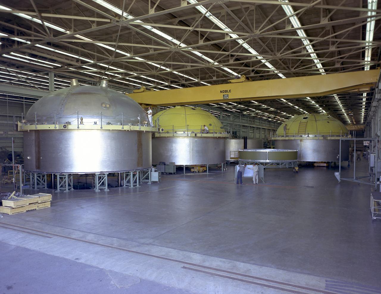
The components of the Saturn V booster (S-IC stage) fuel tank are shown in this photograph. The liquid oxygen tank bulkhead on the left and both halves of the fuel tank were in the Marshall Space Flight Center (MSFC) Manufacturing Engineering Laboratory, building 4707. These components were used at MSFC in structural testing to prove that they could withstand the forces to which they were subjected in flight. Each S-IC stage has two tanks, one for kerosene and one for liquid oxygen, made from such components as these. Thirty-three feet in diameter, they hold a total of 4,400,000 pounds of fuel. Although this tankage was assembled at MSFC, the elements were made by the Boeing Company at Wichita and the Michoud Operations at New Orleans.
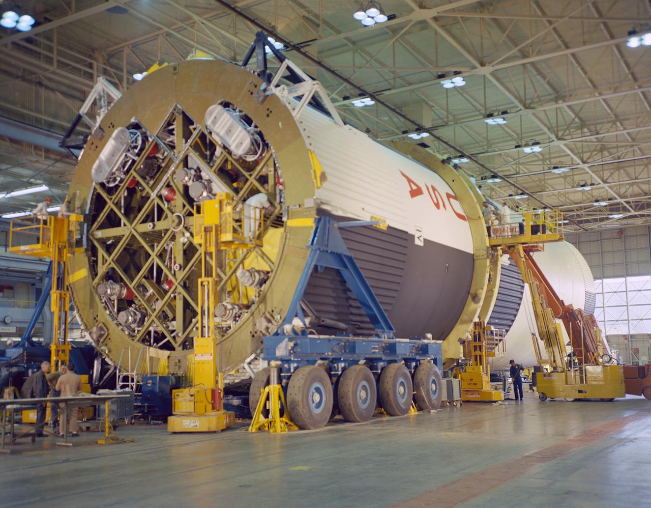
At the Marshall Space Flight Center (MSFC), the fuel tank assembly for the Saturn V S-IC-T (static test stage) fuel tank assembly is mated to the liquid oxygen (LOX) tank in building 4705. This stage underwent numerous static firings at the newly-built S-IC Static Test Stand at the MSFC west test area. The S-IC (first) stage used five F-1 engines that produced a total thrust of 7,500,000 pounds as each engine produced 1,500,000 pounds of thrust. The S-IC stage lifted the Saturn V vehicle and Apollo spacecraft from the launch pad.
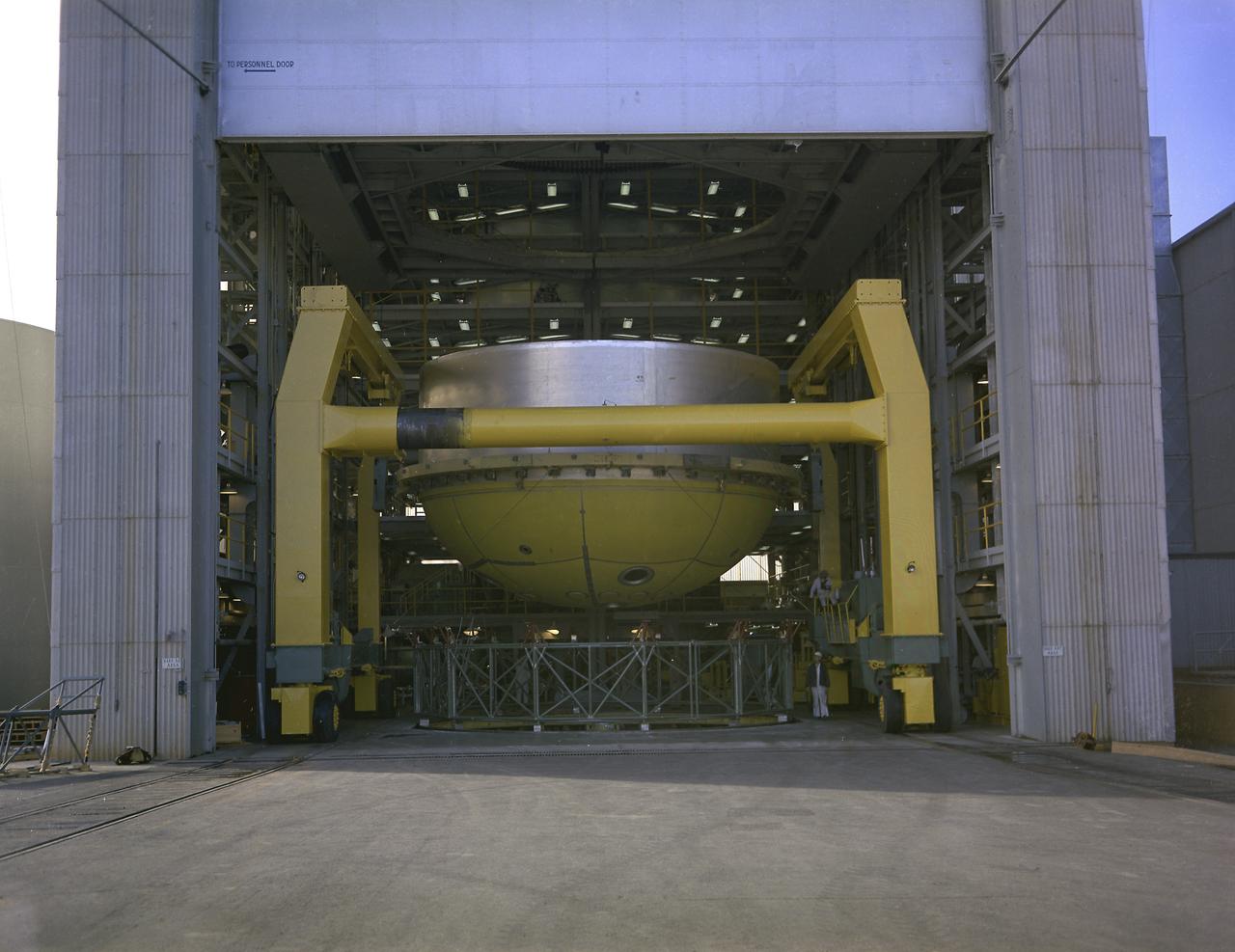
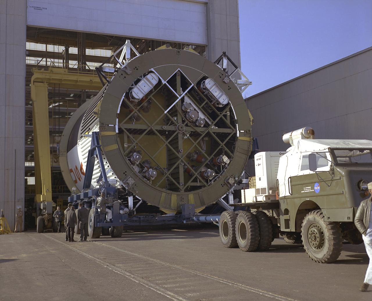
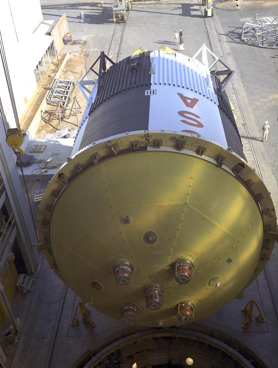
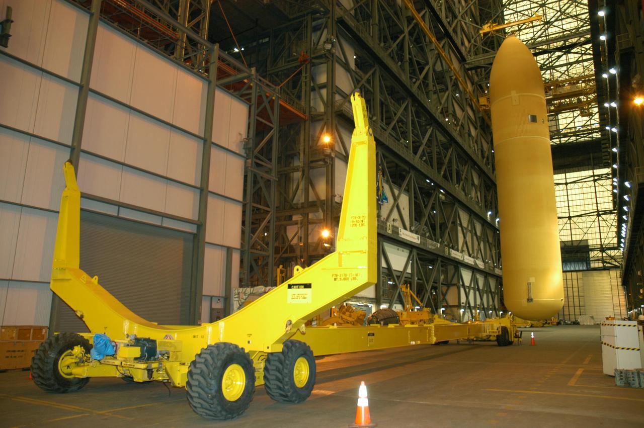
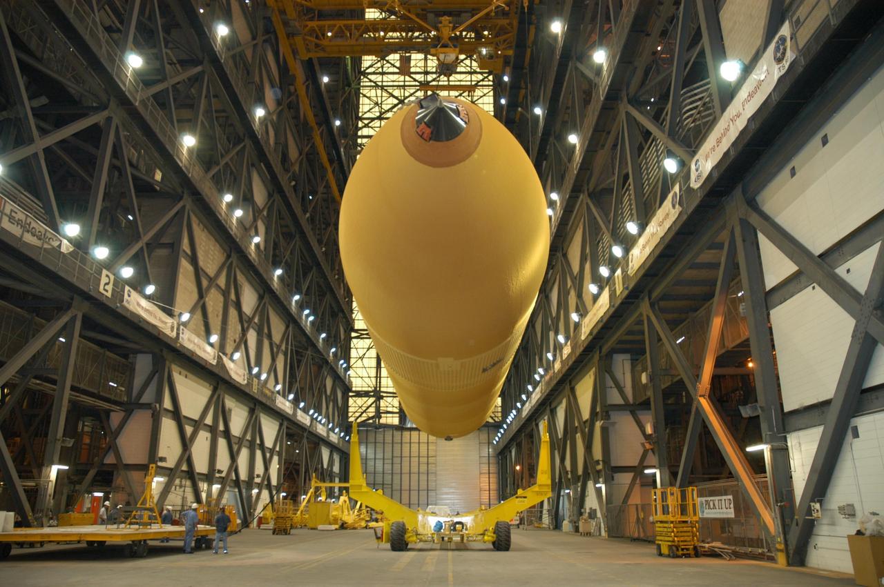
This photograph shows a fuel tank lower half for the Saturn V S-IC-T stage (the S-IC stage for static testing) on a C-frame transporter inside the vertical assembly building at the Marshall Space Flight Center.
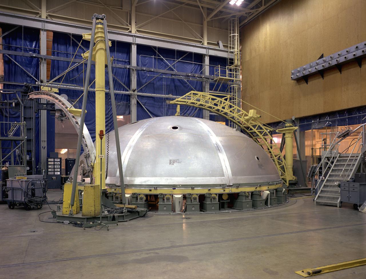
This photograph shows a bulkhead for the Saturn V S-IC stage fuel tank being fabricated at the Manufacturing Engineering Laboratory, building 4704, at the Marshall Space Flight Center.
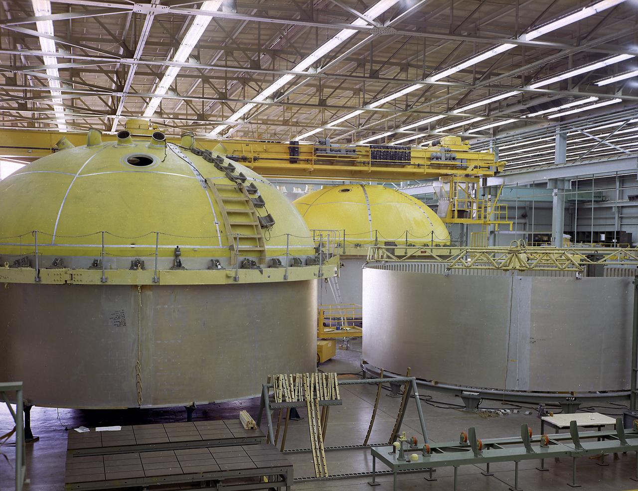
This photograph shows the components for the Saturn V S-IC stage fuel tank assembly in the Manufacturing Engineering Laboratory, building 4707, at the Marshall Space Flight Center (MSFC). Left to right are upper head, lower head, and forward skirt assembly. Thirty-three feet in diameter, they will hold a total of 4,400,000 pounds of fuel. Although this tankage was assembled at MSFC, the elements were made by the Boeing Company at Wichita and the Michould Operations at New Orleans.
Marshall Space Flight Center successfully conducted hydrostatic testing on the Saturn V S-IC (first) stage fuel tank. The first stage was powered by five F-1 engines, that used liquid oxygen and kerosene as its propellant.
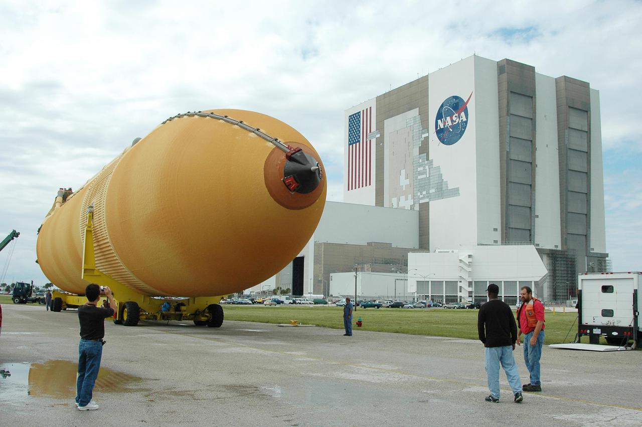
This photograph shows the Saturn V assembled LOX (Liquid Oxygen) and fuel tanks ready for transport from the Manufacturing Engineering Laboratory at Marshall Space Flight Center in Huntsville, Alabama. The tanks were then shipped to the launch site at Kennedy Space Center for a flight. The towering 363-foot Saturn V was a multi-stage, multi-engine launch vehicle standing taller than the Statue of Liberty. Altogether, the Saturn V engines produced as much power as 85 Hoover Dams.
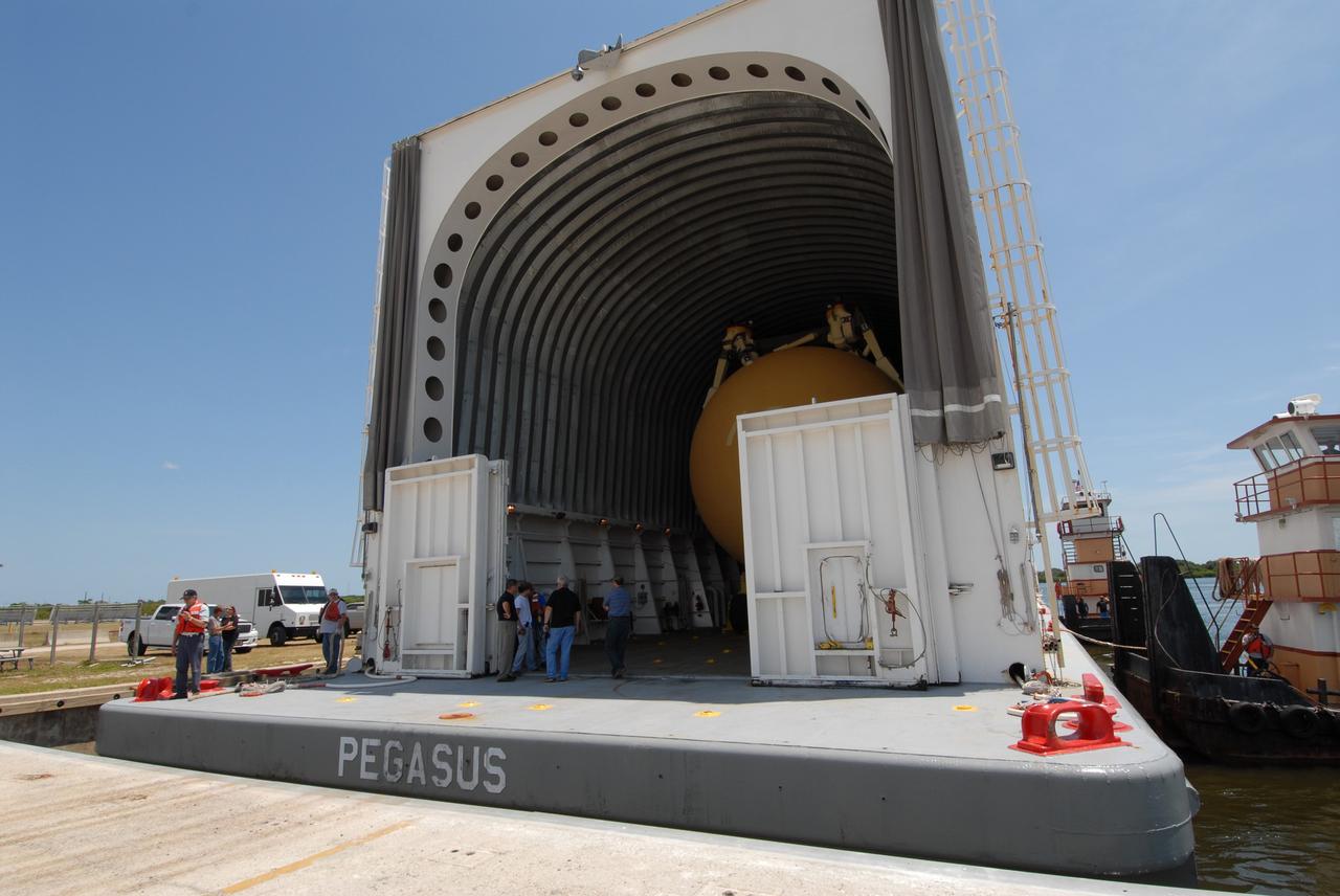
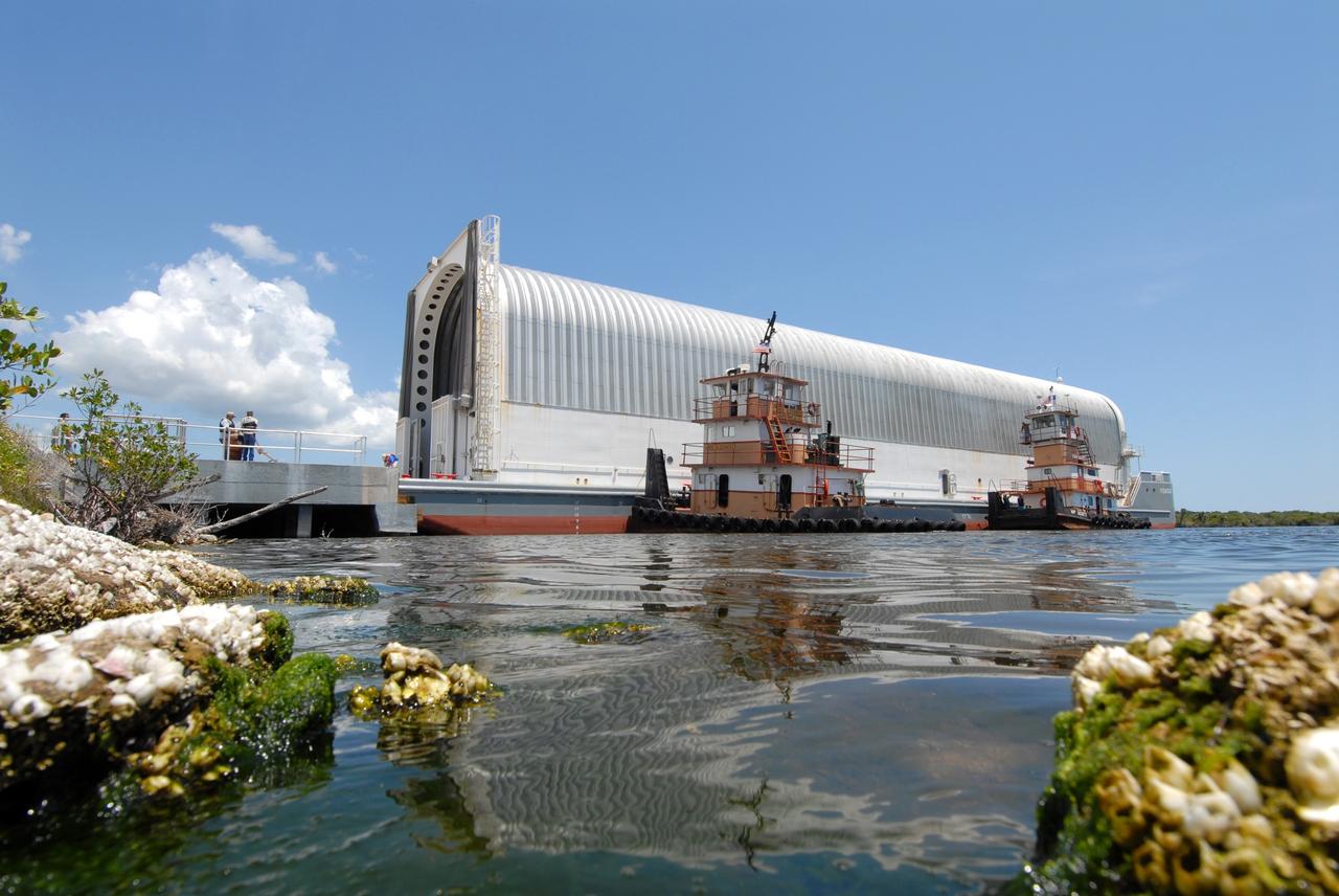
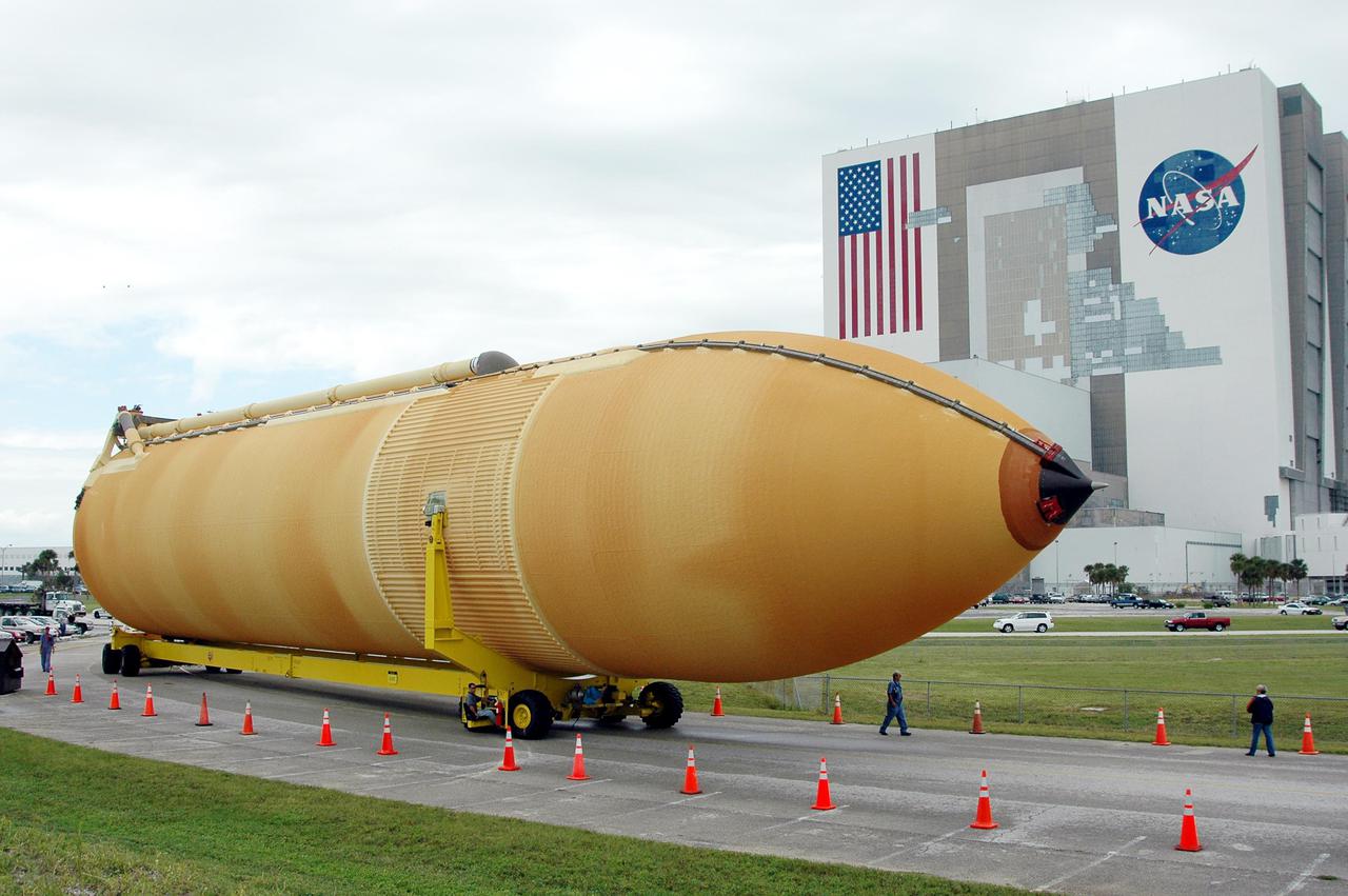
CAPE CANAVERAL, Fla. – The Pegasus barge is docked in the turn basin in the Launch Complex 39 Area at NASA's Kennedy Space Center in Florida. Inside is the external fuel tank, ET- 132, designated for space shuttle Discovery on the STS-128 mission. The tank will be offloaded and transported to a high bay in the Vehicle Assembly Building for checkout. On the STS-128 mission, Discovery will carry science and storage racks to the International Space Station. Launch of Discovery is targeted for Aug. 6. Photo credit: NASA/Troy Cryder
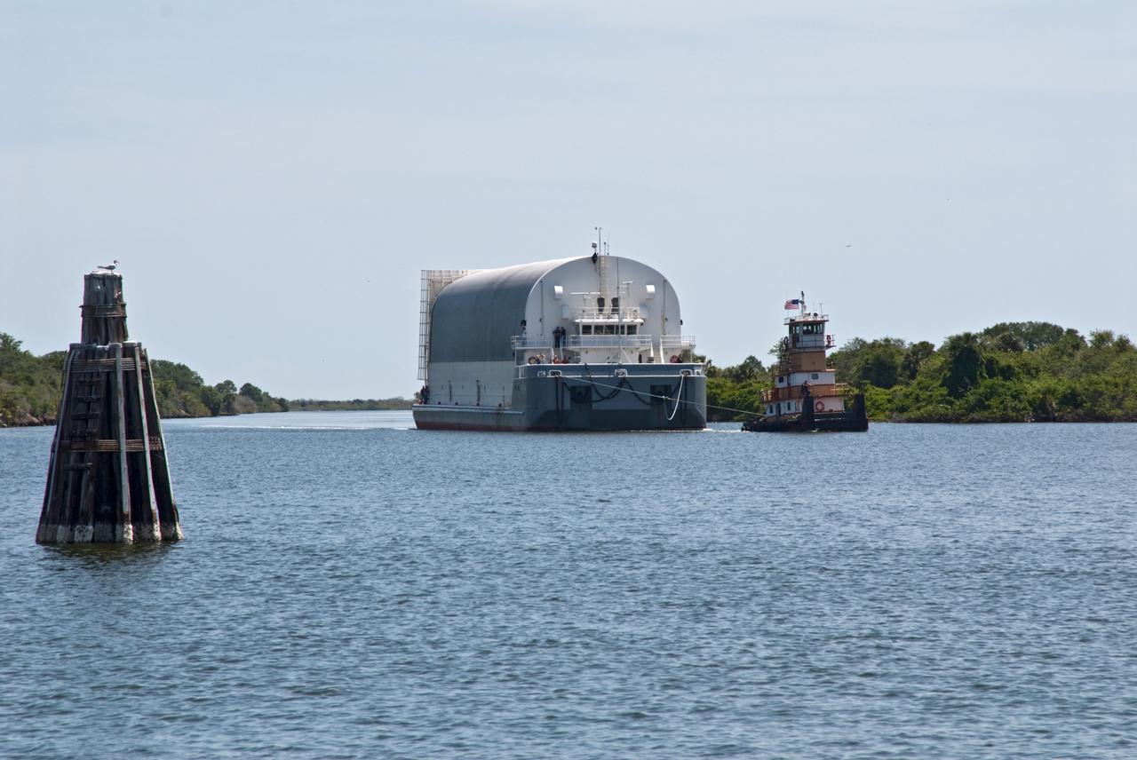
CAPE CANAVERAL, Fla. – Tugboats maneuver the Pegasus barge toward the dock in the turn basin in the Launch Complex 39 Area at NASA's Kennedy Space Center in Florida. The barge holds the external fuel tank, ET- 132, designated for space shuttle Discovery on the STS-128 mission. The tank will be offloaded and transported to a high bay in the Vehicle Assembly Building for checkout. On the STS-128 mission, Discovery will carry science and storage racks to the International Space Station. Launch of Discovery is targeted for Aug. 6. Photo credit: NASA/Troy Cryder
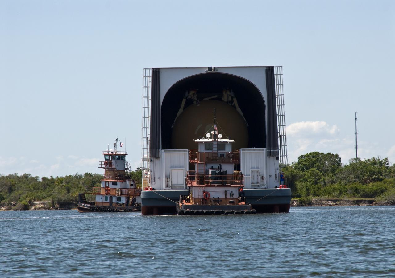
CAPE CANAVERAL, Fla. – The Pegasus barge, towed by a tugboat, enters the turn basin in the Launch Complex 39 Area at NASA's Kennedy Space Center in Florida. The barge holds the external fuel tank, ET- 132, designated for space shuttle Discovery on the STS-128 mission. The tank will be offloaded and transported to a high bay in the Vehicle Assembly Building for checkout. On the STS-128 mission, Discovery will carry science and storage racks to the International Space Station. Launch of Discovery is targeted for Aug. 6. Photo credit: NASA/Troy Cryder
CAPE CANAVERAL, Fla. – The Pegasus barge is docked in the turn basin in the Launch Complex 39 Area at NASA's Kennedy Space Center in Florida. Inside is the external fuel tank, ET- 132, designated for space shuttle Discovery on the STS-128 mission. The tank will be offloaded and transported to a high bay in the Vehicle Assembly Building for checkout. On the STS-128 mission, Discovery will carry science and storage racks to the International Space Station. Launch of Discovery is targeted for Aug. 6. Photo credit: NASA/Troy Cryder
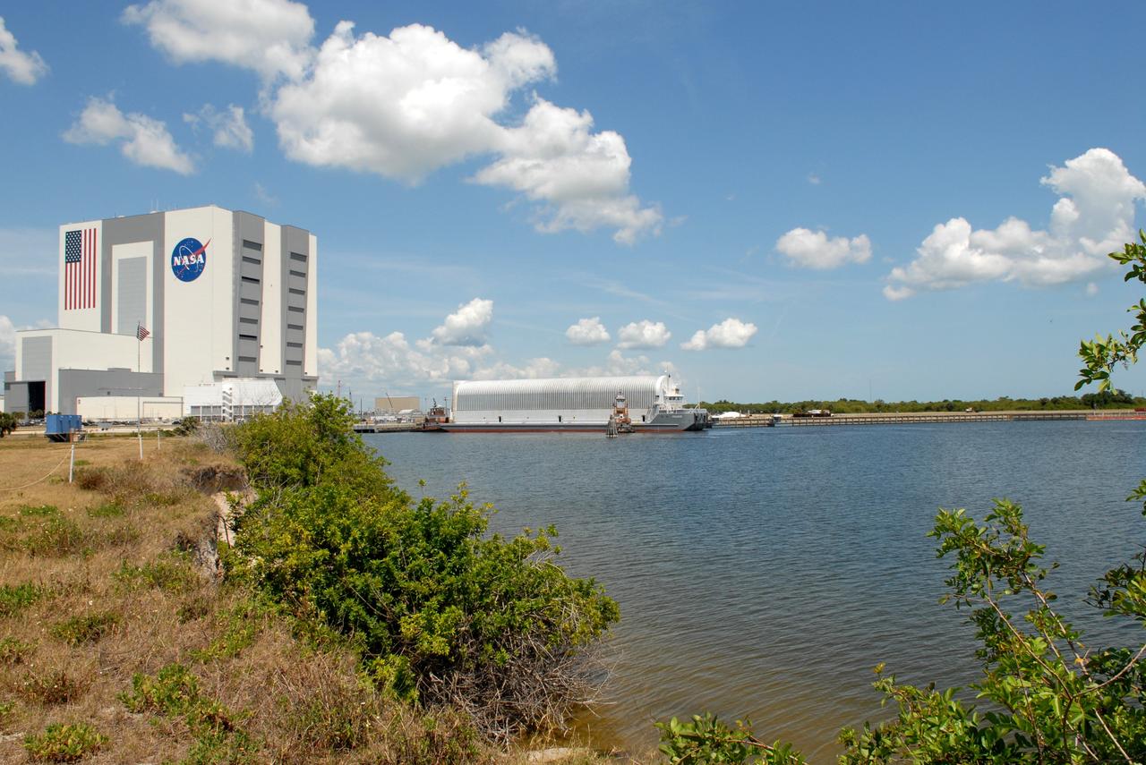
CAPE CANAVERAL, Fla. – Viewed from across the turn basin in the Launch Complex 39 Area at NASA's Kennedy Space Center in Florida, the Pegasus barge is maneuvered up to the dock. In the background at left is the Vehicle Assembly Building. The barge holds the external fuel tank, ET- 132, designated for space shuttle Discovery on the STS-128 mission. The tank will be offloaded and transported to a high bay in the VAB for checkout. On the STS-128 mission, Discovery will carry science and storage racks to the International Space Station. Launch of Discovery is targeted for Aug. 6. Photo credit: NASA/Troy Cryder
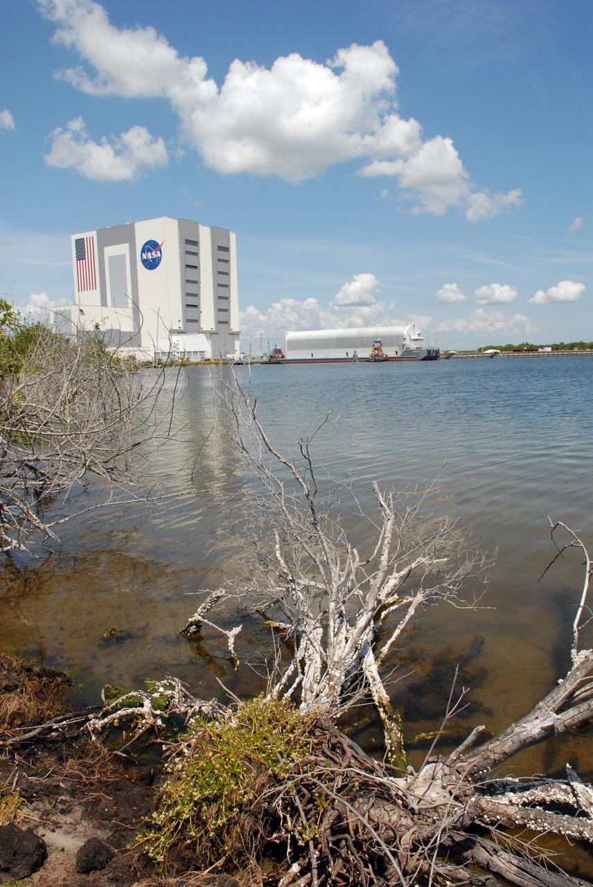
CAPE CANAVERAL, Fla. – Viewed from across the turn basin in the Launch Complex 39 Area at NASA's Kennedy Space Center in Florida, the Pegasus barge is maneuvered up to the dock. In the background at left is the Vehicle Assembly Building. The barge holds the external fuel tank, ET- 132, designated for space shuttle Discovery on the STS-128 mission. The tank will be offloaded and transported to a high bay in the VAB for checkout. On the STS-128 mission, Discovery will carry science and storage racks to the International Space Station. Launch of Discovery is targeted for Aug. 6. Photo credit: NASA/Troy Cryder
This image shows the Saturn V S-IC-T stage (S-IC static test article) fuel tank being attached to the thrust structure in the vehicle assembly building at the Marshall Space Flight Center (MSFC). The S-IC stage utilized five F-1 engines that used liquid oxygen and kerosene as propellant and provided a combined thrust of 7,500,000 pounds.
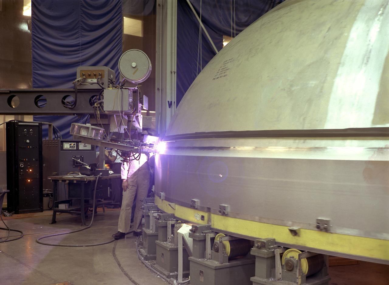
A technician is pictured at the Marshall Space Flight Center welding the Y-ring to the S-IC stage bulkhead and the fuel tank for the Saturn V SA-502 launch vehicle (Apollo 6 mission) in building 4705. The size of the S-IC required a special rig known as the Y-ring to join the tank wall cylinders and domes together. The Y-ring was designed to eliminate lap joints where the tank domes, wall, and adjoining structure (such as the intertank segment) came together.
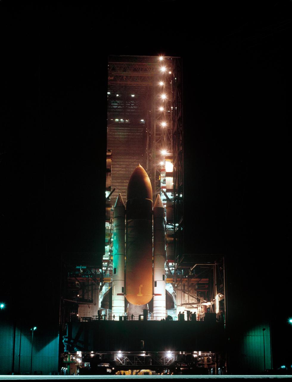
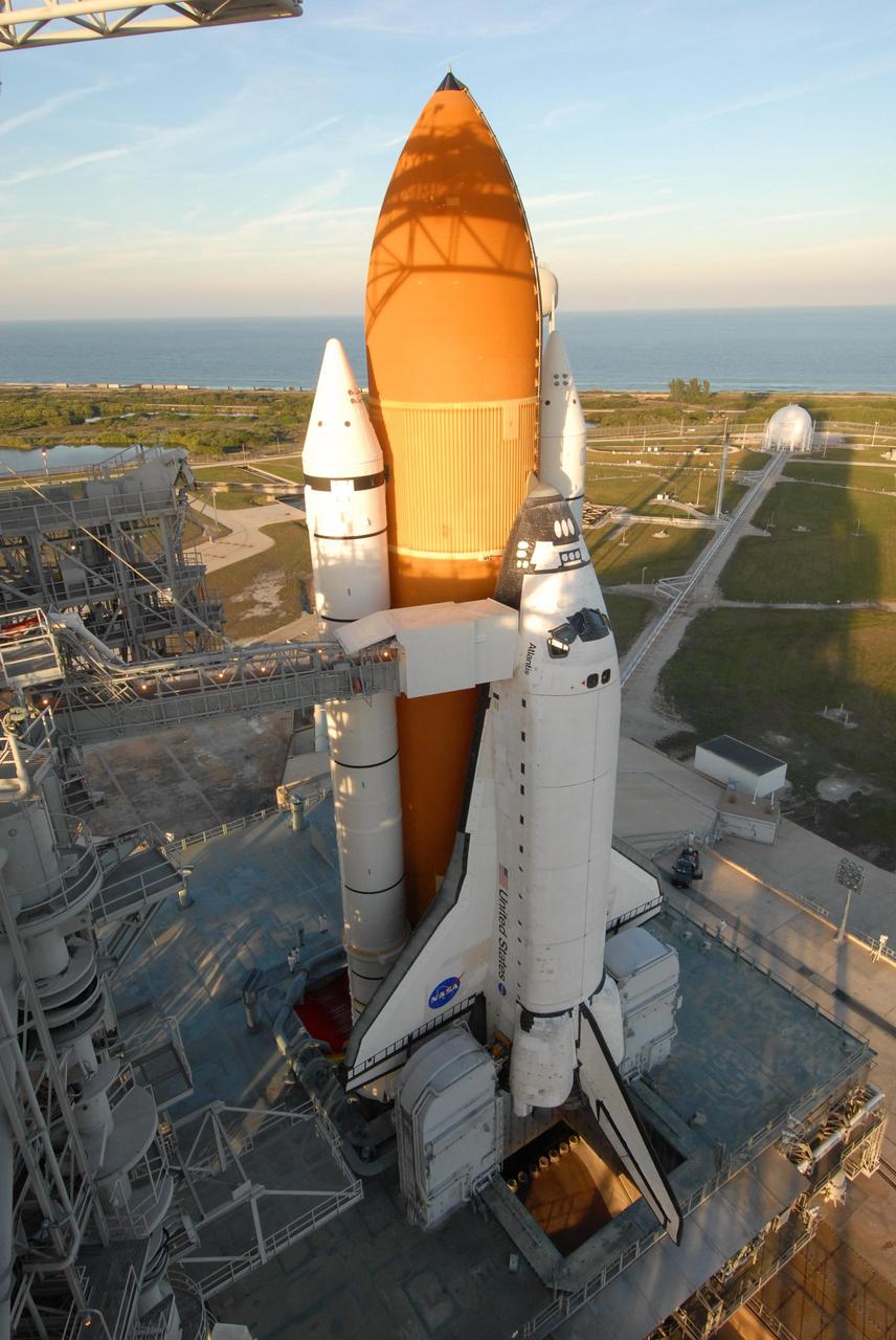
S83-39238 (1 Aug. 1983) --- The giant cluster of spaceflight hardware for NASA's eighth Space Transportation System (STS) mission begins its slow move to the launch pad at launch complex 39 at NASA's Kennedy Space Center (KSC). Following its mating to the two solid rocket boosters (SRB) and the external fuel tank (ET) in the huge vehicle assembly building (VAB), the space shuttle Challenger is slowly moved to the launch pad atop the mobile launch platform. Photo credit: NASA
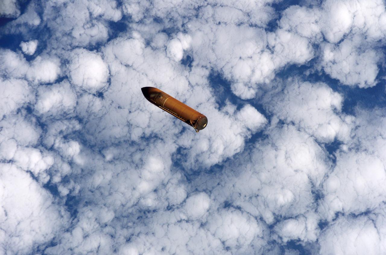
S114-E-5122 (26 July 2005) --- The external fuel tank is jettisoned from the Space Shuttle Discovery and falls toward Earth’s atmosphere during the completion of the launch phase of the STS-114 mission. A blue and white Earth forms the backdrop for this image.
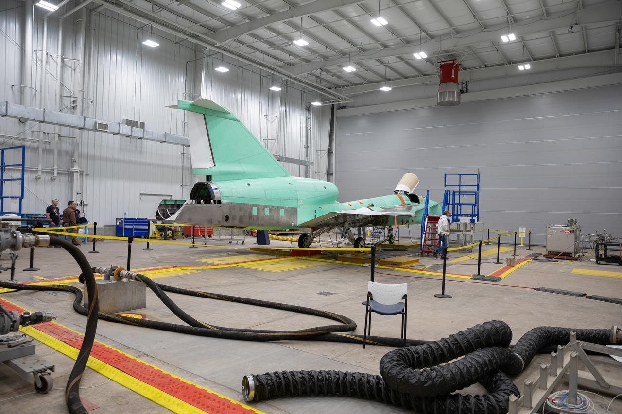
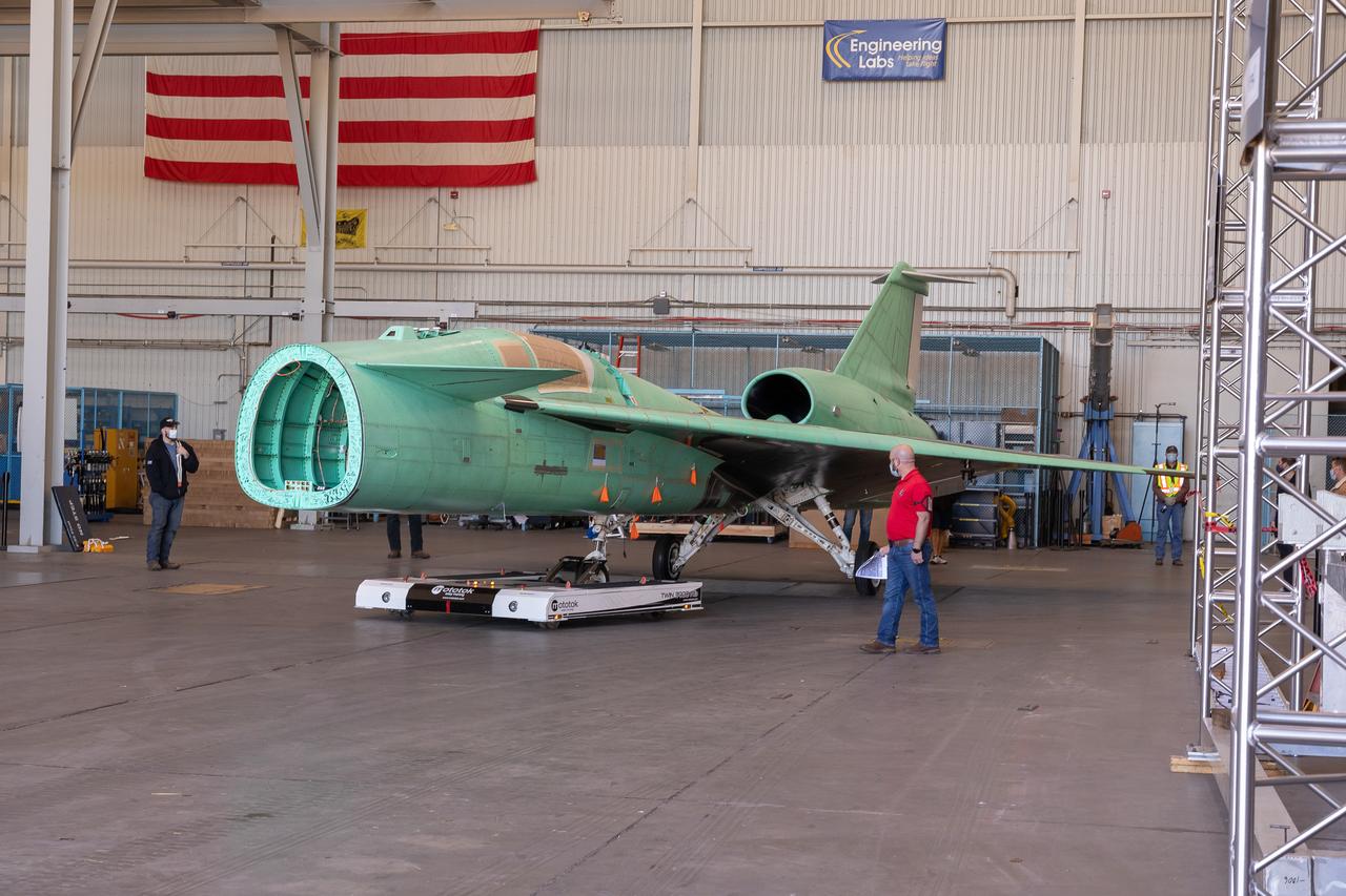
The X-59 sits in the fuel barn at Lockheed Martin in Fort Worth, Texas. While in the fuel barn, the X-59 underwent fuel tank calibration tests. During this phase, the X-59’s gas tanks were filled and fuel-remaining sensors inside the aircraft were checked.
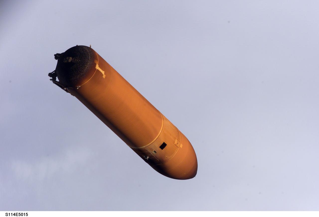
STS114-E-5015 (26 July 2005) ---- Handheld still images taken by Discovery's crew of the external fuel tank as it was jettisoned after launch on July 26 were transmitted to the ground early July 27. Engineers are analyzing these photos as part of the extensive imagery data being gathered to understand debris during the Shuttle's ascent during STS-114. These images of the external tank were taken with the tank closer to the Shuttle than on any past missions due to an earlier maneuver performed by the spacecraft shortly after main engine cutoff.
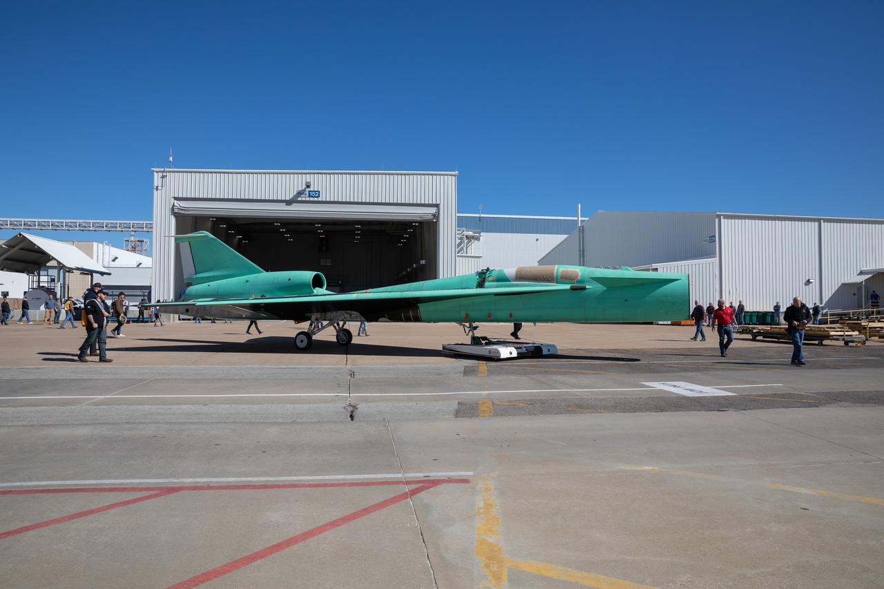
The X-59 is transported to the fuel barn at Lockheed Martin in Fort Worth, Texas to undergo fuel tank calibration tests. During this phase, the X-59’s gas tanks were filled and fuel-remaining sensors inside the aircraft were checked.
The X-59 is transported to the fuel barn at Lockheed Martin in Fort Worth, Texas to undergo fuel tank calibration tests. During this phase, the X-59’s gas tanks were filled and fuel-remaining sensors inside the aircraft were checked.
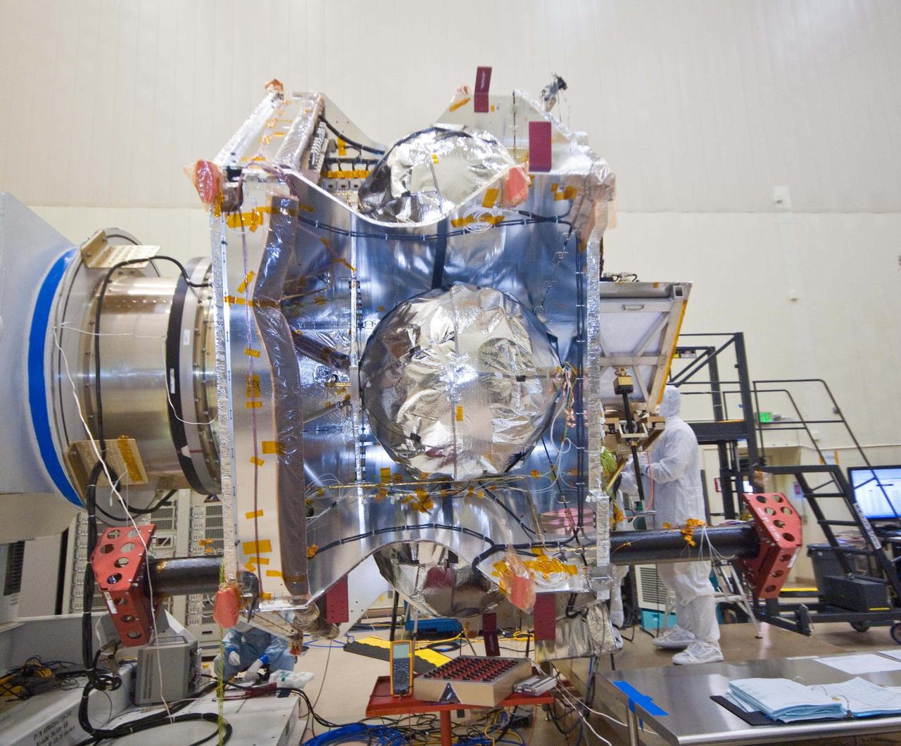
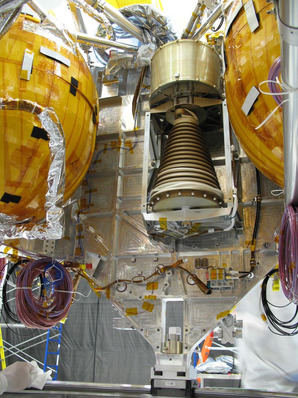
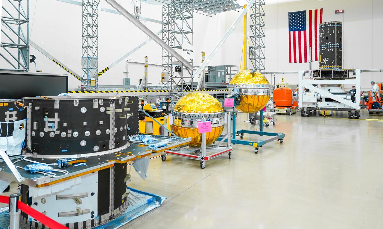
An exposed, side view of NASA Juno spacecraft during its assembly features three of the spacecraft spherical propellant tanks.
This view of a portion of the descent stage of NASA Mars Science Laboratory shows two of the stage three spherical fuel tanks flanking the bridle device assembly.
Stennis Space Center engineers are preparing to conduct water tests on an updated version of the scissors duct component of the J-2X engine. Measuring about 2 feet long and about 8 inches in diameter, the duct on the J-2X predecessor, the J-2, connected its fuel turbo pumps to the flight vehicle's upper stage run tanks. According to NASA's J-2X project manager at SSC, Gary Benton, the water tests should establish the limits of the duct's ability to withstand vibration.
Technicians carefully install a piece of equipment to house Gateway’s xenon fuel tanks, part of its advanced electric propulsion system.
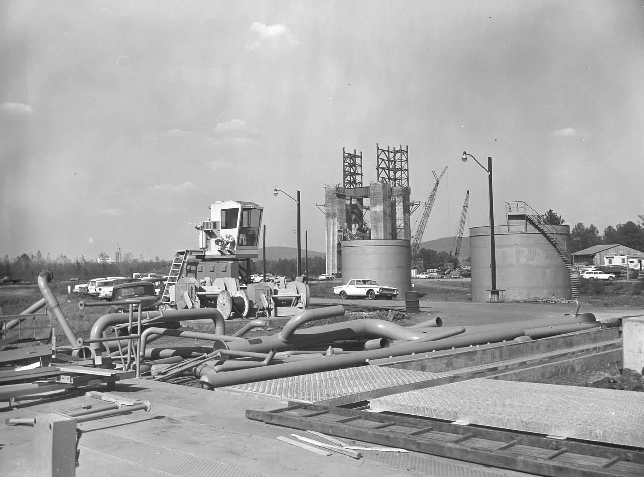
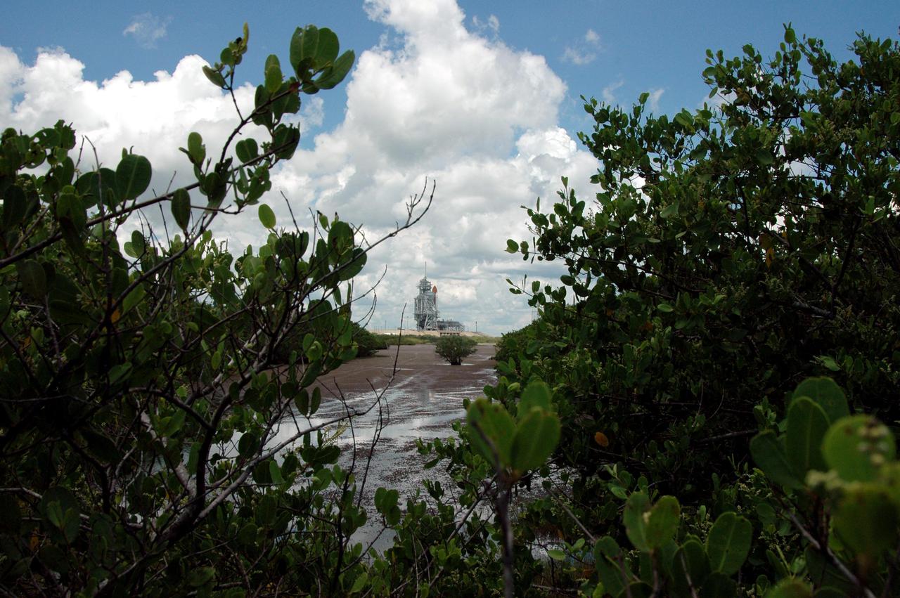
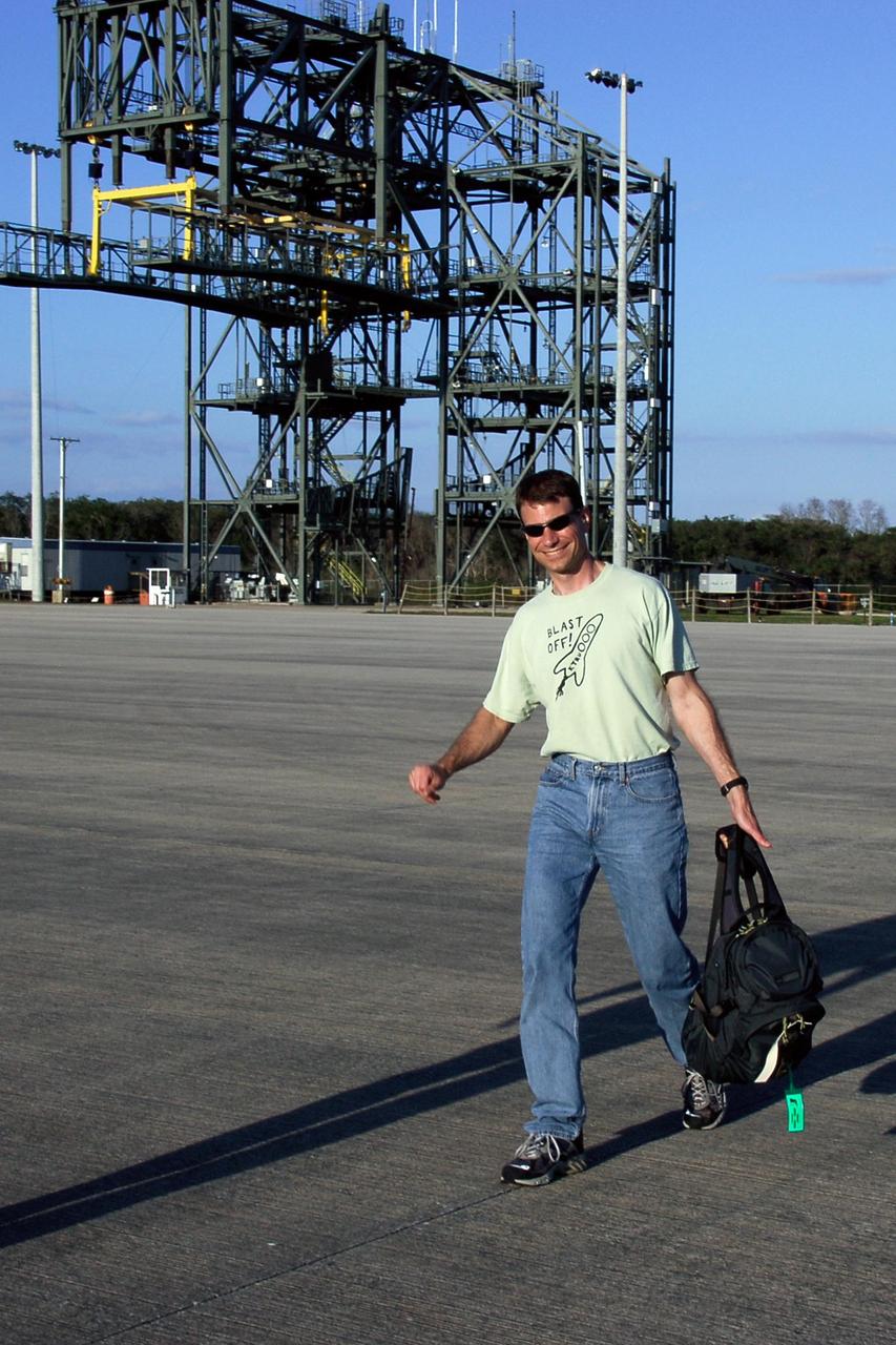
At its founding, the Marshall Space Flight Center (MSFC) inherited the Army’s Jupiter and Redstone test stands, but much larger facilities were needed for the giant stages of the Saturn V. From 1960 to 1964, the existing stands were remodeled and a sizable new test area was developed. The new comprehensive test complex for propulsion and structural dynamics was unique within the nation and the free world, and they remain so today because they were constructed with foresight to meet the future as well as on going needs. Construction of the S-IC Static test stand complex began in 1961 in the west test area of MSFC, and was completed in 1964. The S-IC static test stand was designed to develop and test the 138-ft long and 33-ft diameter Saturn V S-IC first stage, or booster stage, weighing in at 280,000 pounds. Required to hold down the brute force of a 7,500,000-pound thrust produced by 5 F-1 engines, the S-IC static test stand was designed and constructed with the strength of hundreds of tons of steel and 12,000,000 pounds of cement, planted down to bedrock 40 feet below ground level. The foundation walls, constructed with concrete and steel, are 4 feet thick. The base structure consists of four towers with 40-foot-thick walls extending upward 144 feet above ground level. The structure was topped by a crane with a 135-foot boom. With the boom in the upright position, the stand was given an overall height of 405 feet, placing it among the highest structures in Alabama at the time. In addition to the stand itself, related facilities were constructed during this time. Northeast of the massive S-IC test stand, the F-1 Engine test stand was built. The F-1 test stand is a vertical engine firing test stand, 239 feet in elevation and 4,600 square feet in area at the base, and was designed to assist in the development of the F-1 Engine. Capability was provided for static firing of 1.5 million pounds of thrust using liquid oxygen and kerosene. Like the S-IC stand, the foundation of the F-1 stand is keyed into the bedrock approximately 40 feet below grade. This photo depicts the fuel tanks that housed kerosene and just beyond those is the F-1 test stand.
Hardware for the Gateway space station’s Power and Propulsion element, including its primary structure and fuel tanks ready for assembly, are shown at Maxar Space Systems in Palo Alto, California.
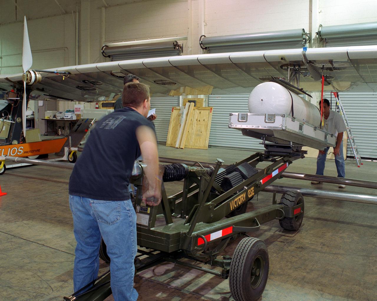
Technicians for AeroVironment, Inc., jack up a pressure tank to the wing of the Helios Prototype solar-electric flying wing. The tank carries pressurized hydrogen to fuel an experimental fuel cell system that powered the aircraft at night during an almost two-day long-endurance flight demonstration in the summer of 2003.
The fuel tank assembly of the Saturn V S-IC (first) stage supported with the aid of a C frame on the transporter was readied to be transported to the Marshall Space Flight Center, building 4705. The fuel tank carried kerosene (RP-1) as its fuel. The S-IC stage utilized five F-1 engines that used kerosene and liquid oxygen as propellant and each engine provided 1,500,000 pounds of thrust. This stage lifted the entire vehicle and Apollo spacecraft from the launch pad.
CAPE CANAVERAL, Fla. -- In the transfer aisle of the Vehicle Assembly Building at NASA's Kennedy Space Center in Florida, external fuel tank 130 is raised to a vertical position. The tank will be lifted into high bay 2 for checkout before stacking with the solid rocket boosters and space shuttle Atlantis for the STS-125 mission. The fuel tank was previously designated for the STS-127 mission. The STS-125 Hubble servicing mission is targeted to launch May 12. Photo credit: NASA/Tim Jacobs

CAPE CANAVERAL, Fla. -- In the transfer aisle of the Vehicle Assembly Building at NASA's Kennedy Space Center in Florida, external fuel tank 130 is fitted with a crane to lift it off the transporter. The tank will be raised to vertical and lifted into high bay 2 for checkout before stacking with the solid rocket boosters and space shuttle Endeavour for the STS-125 mission. The fuel tank was previously designated for the STS-127 mission. The STS-125 Hubble servicing mission is targeted to launch May 12. Photo credit: NASA/Tim Jacobs

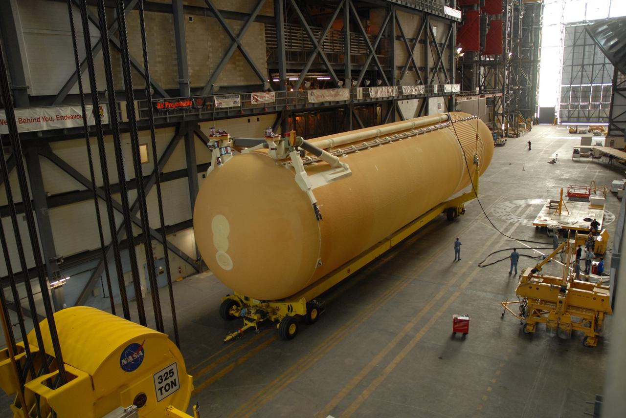
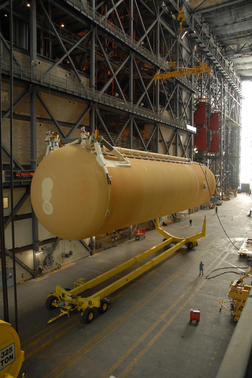
CAPE CANAVERAL, Fla. -- External Tank 130 rolls into the Vehicle Assembly Building at NASA's Kennedy Space Center in Florida. The Pegasus barge transported the fuel tank from the Michoud Assembly Facility in New Orleans. ET 130, which will be used on the Hubble servicing mission, STS-125, will be moved into a high bay for checkout. The fuel tank was previously designated for the STS-127 mission. Photo credit: NASA/Jack Pfaller

CAPE CANAVERAL, Fla. -- In the Vehicle Assembly Building at NASA's Kennedy Space Center in Florida, the vertical external fuel tank 130 is suspended by a crane over the transfer aisle. The tank will be lifted into high bay 2 for checkout before stacking with the solid rocket boosters and space shuttle Atlantis for the STS-125 mission. The fuel tank was previously designated for the STS-127 mission. The STS-125 Hubble servicing mission is targeted to launch May 12. Photo credit: NASA/Tim Jacobs
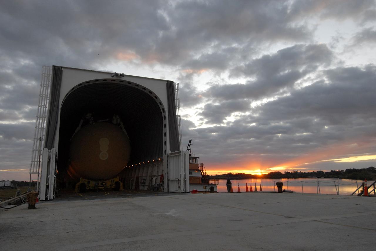
CAPE CANAVERAL, Fla. -- Just after sunrise, External Tank 130 is seen inside the Pegasus barge docked at the turn basin at NASA's Kennedy Space Center in Florida. The barge transported the fuel tank from the Michoud Assembly Facility in New Orleans. ET 130, which will be used on the Hubble servicing mission, STS-125, will be moved to the Vehicle Assembly Building and into a high bay for checkout. The fuel tank was previously designated for the STS-127 mission. Photo credit: NASA/Jack Pfaller
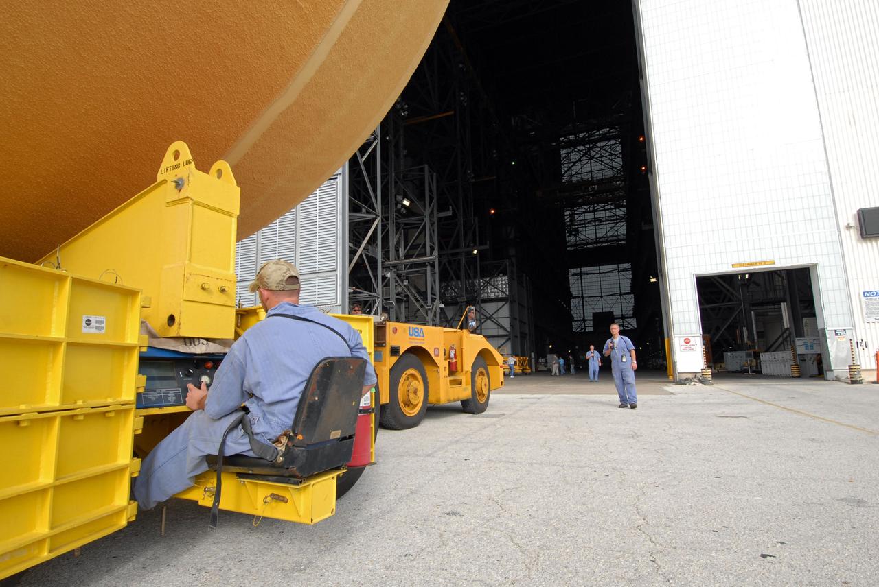
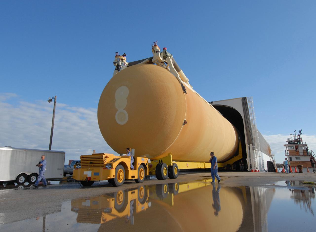
CAPE CANAVERAL, Fla. -- Controlled by a United Space Alliance technician, a transporter moves External Tank 130 toward the open door of the Vehicle Assembly Building at NASA's Kennedy Space Center in Florida. The Pegasus barge transported the fuel tank from the Michoud Assembly Facility in New Orleans. ET 130, which will be used on the Hubble servicing mission, STS-125, will be moved into a high bay for checkout. The fuel tank was previously designated for the STS-127 mission. Photo credit: NASA/Jack Pfaller
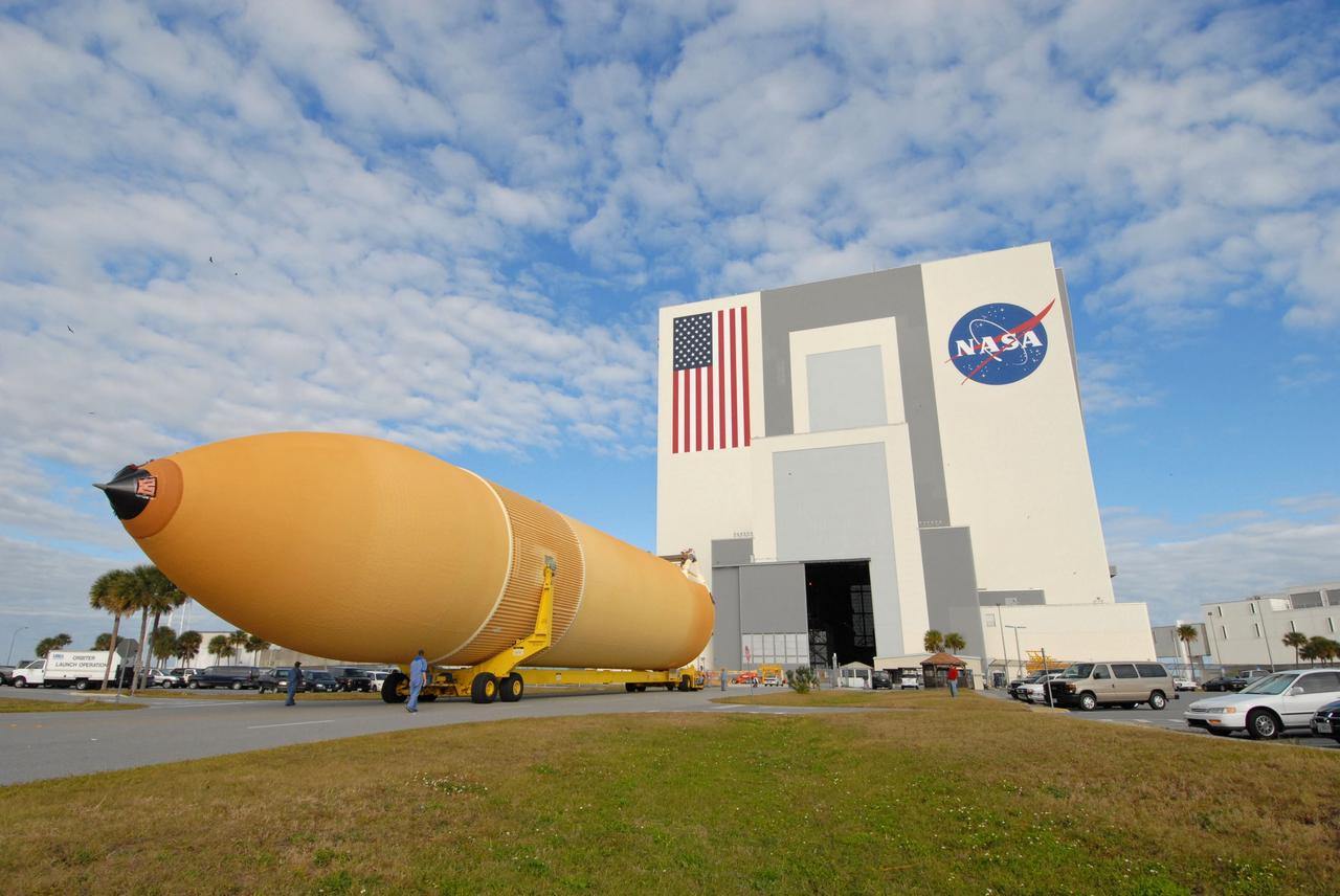
CAPE CANAVERAL, Fla. -- External Tank 130 rolls toward the Vehicle Assembly Building at NASA's Kennedy Space Center in Florida. The Pegasus barge transported the fuel tank from the Michoud Assembly Facility in New Orleans. ET 130, which will be used on the Hubble servicing mission, STS-125, will be moved into a high bay for checkout. The fuel tank was previously designated for the STS-127 mission. Photo credit: NASA/Jack Pfaller
CAPE CANAVERAL, Fla. -- In the transfer aisle of the Vehicle Assembly Building at NASA's Kennedy Space Center in Florida, external fuel tank 130 is lifted off its transporter. The tank will be raised to vertical and lifted into high bay 2 for checkout before stacking with the solid rocket boosters and space shuttle Atlantis for the STS-125 mission. The fuel tank was previously designated for the STS-127 mission. The STS-125 Hubble servicing mission is targeted to launch May 12. Photo credit: NASA/Tim Jacobs
CAPE CANAVERAL, Fla. -- External Tank 130 moves out of the Pegasus barge docked at the turn basin at NASA's Kennedy Space Center in Florida. The barge transported the fuel tank from the Michoud Assembly Facility in New Orleans. ET 130, which will be used on the Hubble servicing mission, STS-125, will be moved to the Vehicle Assembly Building and into a high bay for checkout. The fuel tank was previously designated for the STS-127 mission. Photo credit: NASA/Jack Pfaller
CAPE CANAVERAL, Fla. -- In the transfer aisle of the Vehicle Assembly Building at NASA's Kennedy Space Center in Florida, external fuel tank 130 is fitted with a crane to lift it off the transporter. The tank will be raised to vertical and lifted into high bay 2 for checkout before stacking with the solid rocket boosters and space shuttle Endeavour for the STS-125 mission. The fuel tank was previously designated for the STS-127 mission. The STS-125 Hubble servicing mission is targeted to launch May 12. Photo credit: NASA/Tim Jacobs
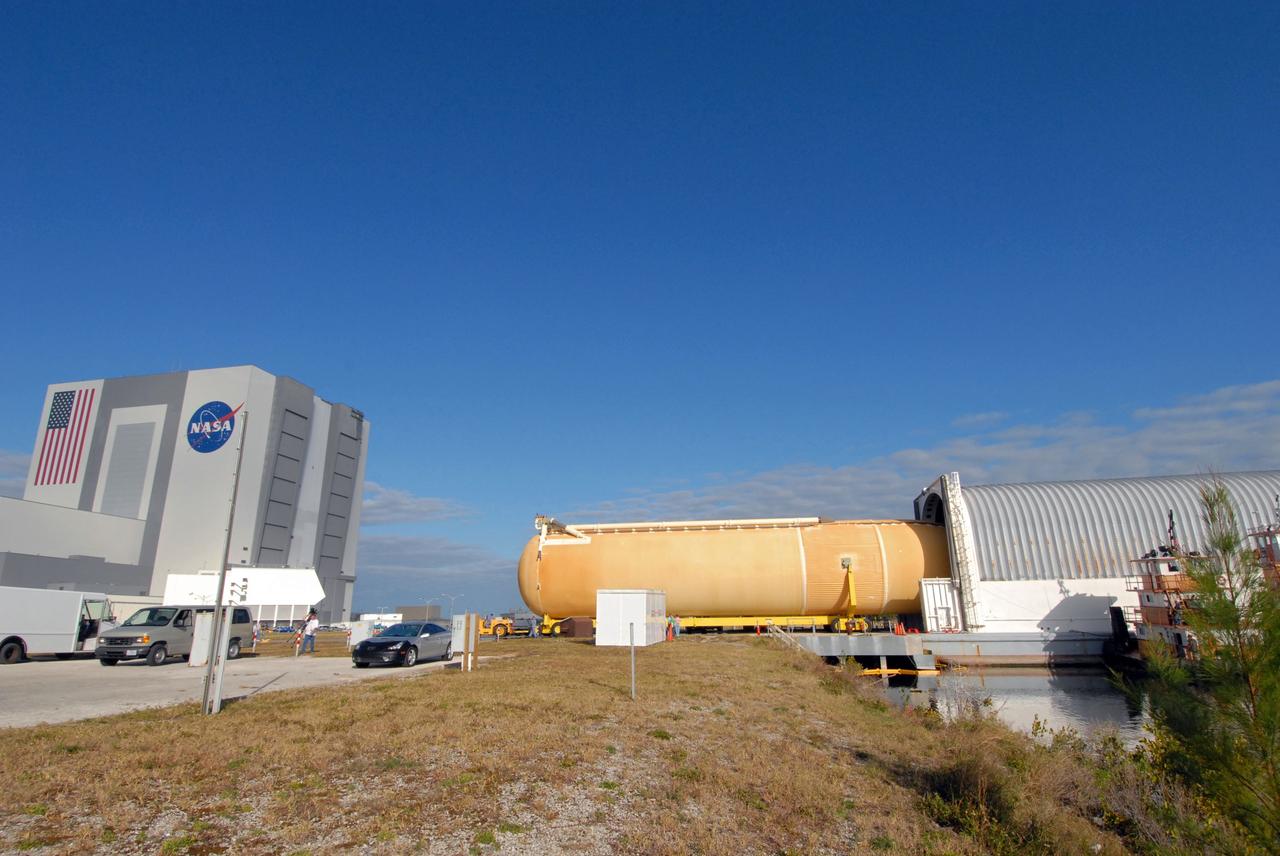
CAPE CANAVERAL, Fla. -- External Tank 130 moves out of the Pegasus barge docked at the turn basin at NASA's Kennedy Space Center in Florida. The barge transported the fuel tank from the Michoud Assembly Facility in New Orleans. ET 130, which will be used on the Hubble servicing mission, STS-125, is being moved to the Vehicle Assembly Building, seen at left, and into a high bay for checkout. The fuel tank was previously designated for the STS-127 mission. Photo credit: NASA/Jack Pfaller
CAPE CANAVERAL, Fla. -- In the transfer aisle of the Vehicle Assembly Building at NASA's Kennedy Space Center in Florida, external fuel tank 130 is lifted off its transporter. The tank will be raised to vertical and lifted into high bay 2 for checkout. The fuel tank was previously designated for the STS-127 mission. The STS-125 Hubble servicing mission is targeted to launch May 12. Photo credit: NASA/Tim Jacobs
This is a picture of the assembled liquid oxygen (LOX) tank for the Saturn V S-IC (first) stage, with A-frame, that arrived to be mated to the fuel tank at a later date at the Marshall Space Flight Center, building 4705.
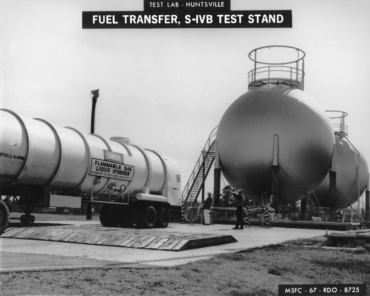
Marshall Space Flight Center (MSFC) workers fill fuel tanks with liquid hydrogen used for test firing at the S-IVB (Dynamic) Test Stand.

A spider beam for cornecting the Saturn I fuel tanks is being positioned in the fabrication and engineering laboratory of the Marshall Space Flight Center (MSFC).
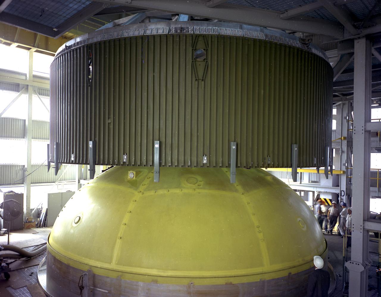
This photograph depicts a forward skirt being placed on the liquid oxygen tank for Saturn V S-IC (first) stage in the Manufacturing Engineering Laboratory at the Marshall Space Flight Center. Thirty-three feet in diameter, the fuel tanks hold a total of 4,400,000 pounds of fuel. Although this tankage was assembled at MSFC, the elements were made by the Boeing Company at Wichita and the Michoud Operations at New Orleans.
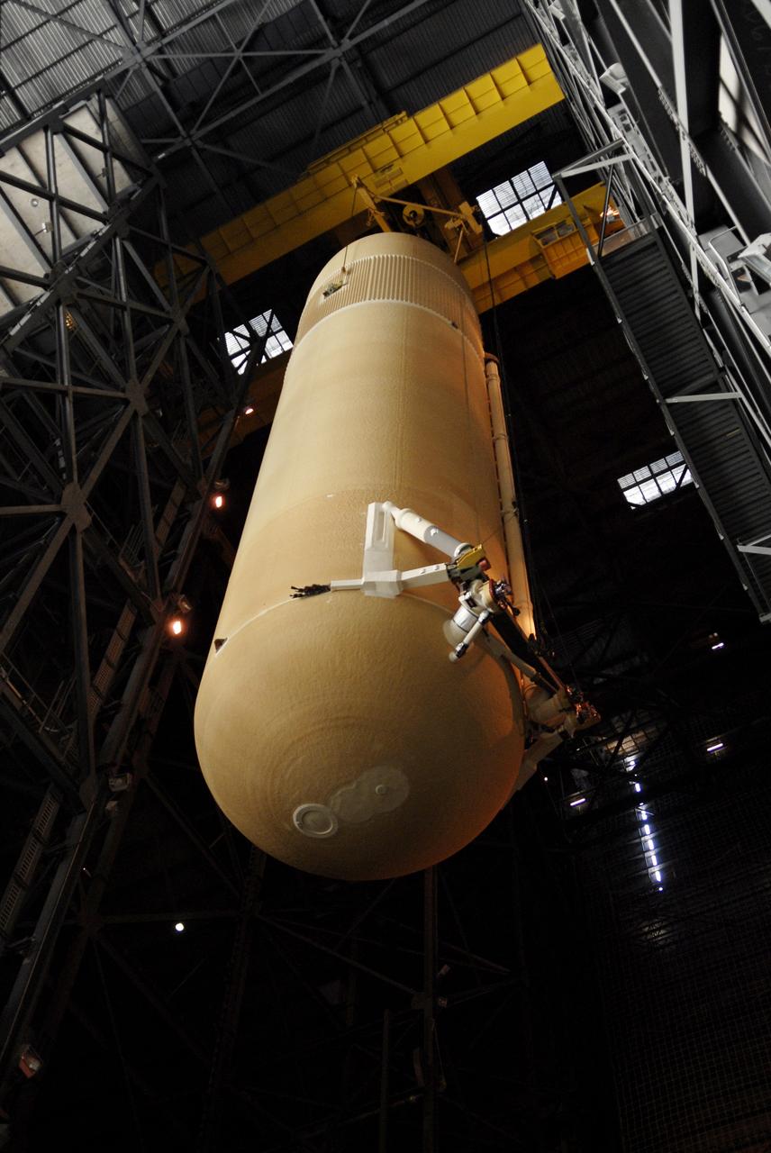
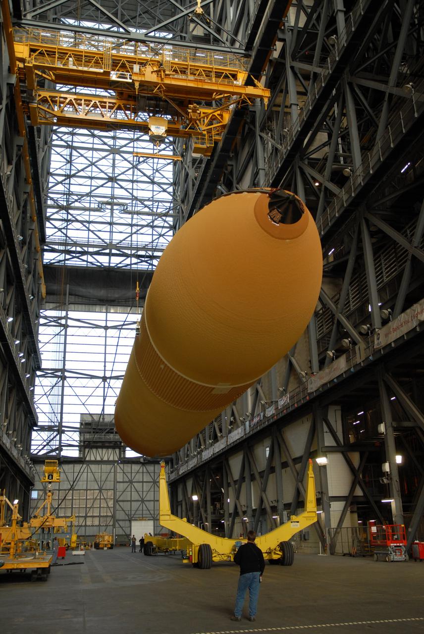
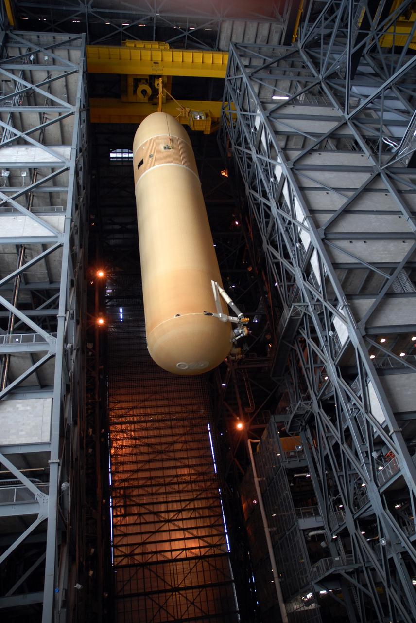
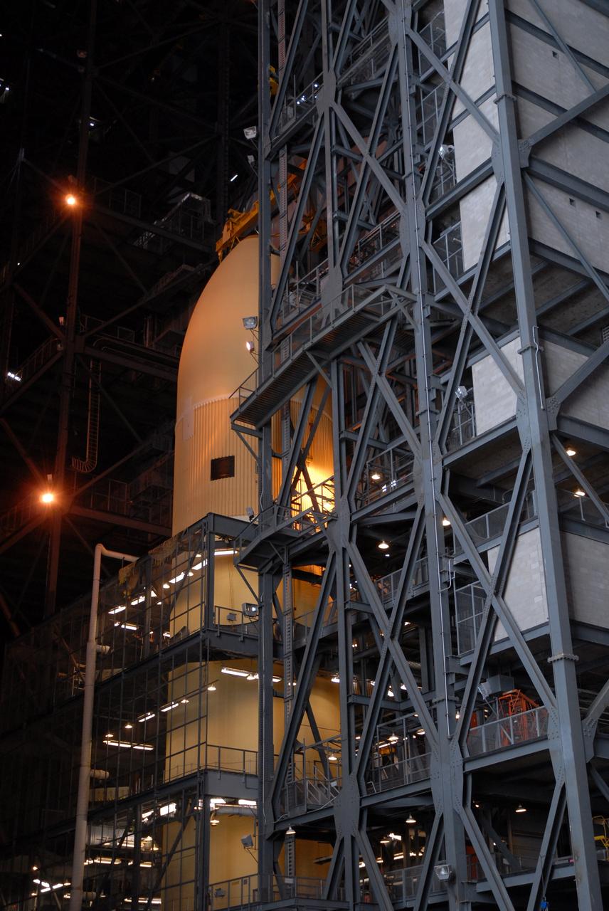
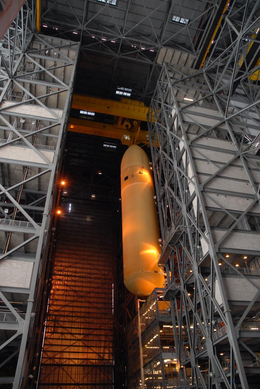
CAPE CANAVERAL, Fla. – In the Vehicle Assembly Building at NASA's Kennedy Space Center in Florida, external fuel tank ET-131 has been lifted into the upper levels and is moving above a high bay. The fuel tank will be lowered onto a stand for checkout. ET-131 will be used on space shuttle Endeavour's STS-127 mission. Payload for the mission is the Japanese Experiment Module's Experiment Logistics Module-Exposed Section, or ELM-ES. Launch is targeted for June. Photo credit: NASA/Kim Shiflett

KENNEDY SPACE CENTER, FLA. - Lloyd Pierce, a NASA test engineer, checks electronic components related to the faulty sensor readings in the liquid hydrogen tank low-level fuel cut-off sensor. The sensor failed a routine prelaunch check during the launch July 13, causing mission managers to scrub Discovery's first launch attempt. The sensor protects the Shuttle's main engines by triggering their shutdown in the event fuel runs unexpectedly low. The sensor is one of four inside the liquid hydrogen section of the External Tank (ET).
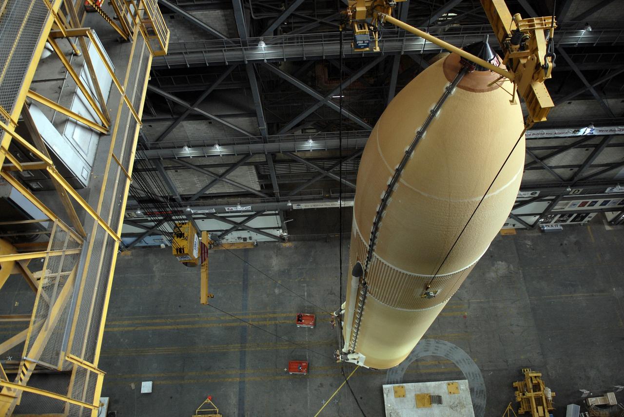
CAPE CANAVERAL, Fla. – The suspension of external fuel tank ET-131 over the transfer aisle of the Vehicle Assembly Building at NASA's Kennedy Space Center in Florida is viewed from an upper level. The fuel tank will be lifted into the upper levels and lowered into a high bay for checkout. ET-131 will be used on space shuttle Endeavour's STS-127 mission. Payload for the mission is the Japanese Experiment Module's Experiment Logistics Module-Exposed Section, or ELM-ES. Launch is targeted for June. Photo credit: NASA/Kim Shiflett
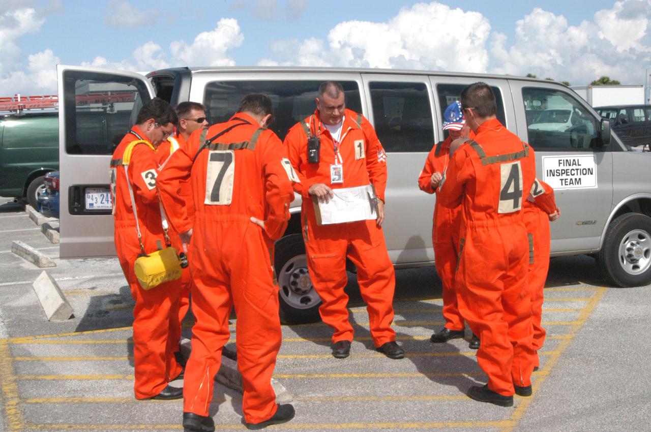
KENNEDY SPACE CENTER, FLA. - Members of the ice team review final details before heading to Launch Pad 39B and their part in the launch of Space Shuttle Discovery on Return to Flight mission STS-114. After the fuel tanking, they will be scanning and inspecting the fuel tank and other hardware on the Space Shuttle for any evidence of ice or debris. Discovery is scheduled to launch on the historic Return to Flight mission STS-114 at 3:51 p.m. July 13 with a crew of seven.
CAPE CANAVERAL, Fla. -- Suspended by a crane in the Vehicle Assembly Building at NASA's Kennedy Space Center in Florida, external fuel tank 130 is moved into high bay 2 for checkout before stacking with the solid rocket boosters and space shuttle Atlantis for the STS-125 mission. The fuel tank was previously designated for the STS-127 mission. The STS-125 Hubble servicing mission is targeted to launch May 12. Photo credit: NASA/Tim Jacobs
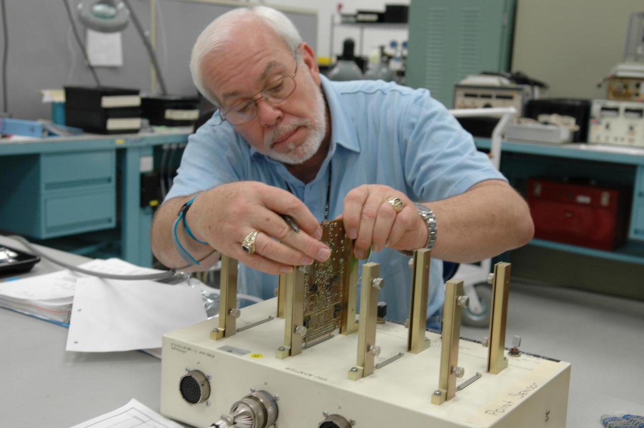
KENNEDY SPACE CENTER, FLA. - Lloyd Pierce, a NASA test engineer, checks electronic components related to the faulty sensor readings in the liquid hydrogen tank low-level fuel cut-off sensor. The sensor failed a routine prelaunch check during the launch July 13, causing mission managers to scrub Discovery's first launch attempt. The sensor protects the Shuttle's main engines by triggering their shutdown in the event fuel runs unexpectedly low. The sensor is one of four inside the liquid hydrogen section of the External Tank (ET).
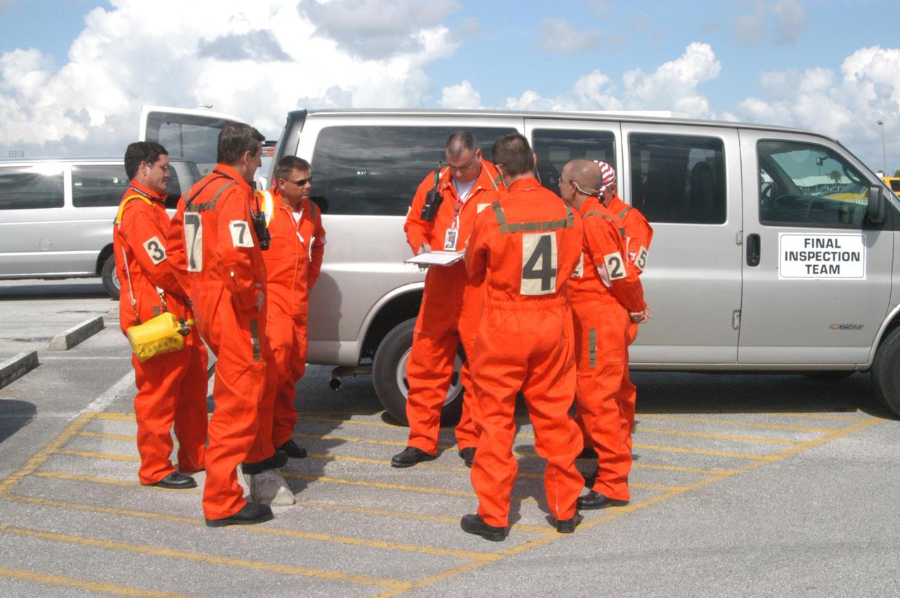
KENNEDY SPACE CENTER, FLA. - Members of the ice team review final details before heading to Launch Pad 39B and their part in the launch of Space Shuttle Discovery on Return to Flight mission STS-114. After the fuel tanking, they will be scanning and inspecting the fuel tank and other hardware on the Space Shuttle for any evidence of ice or debris. Discovery is scheduled to launch on the historic Return to Flight mission STS-114 at 3:51 p.m. July 13 with a crew of seven.
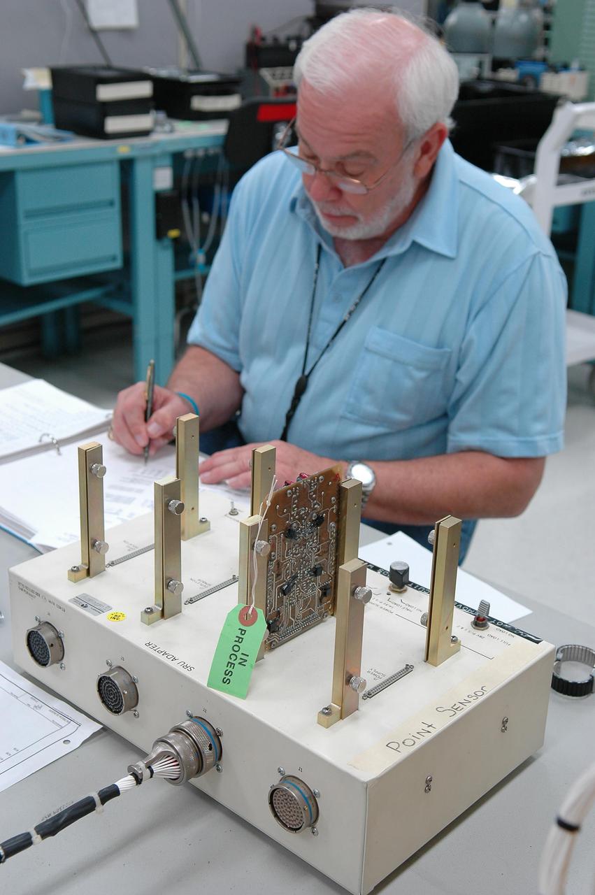
KENNEDY SPACE CENTER, FLA. - Lloyd Pierce, a NASA test engineer, checks electronic components related to the faulty sensor readings in the liquid hydrogen tank low-level fuel cut-off sensor. The sensor failed a routine prelaunch check during the launch July 13, causing mission managers to scrub Discovery's first launch attempt. The sensor protects the Shuttle's main engines by triggering their shutdown in the event fuel runs unexpectedly low. The sensor is one of four inside the liquid hydrogen section of the External Tank (ET).
CAPE CANAVERAL, Fla. -- In the Vehicle Assembly Building at NASA's Kennedy Space Center in Florida, external fuel tank 130 is in place in high bay 2 where it will undergo checkout before stacking with the solid rocket boosters and space shuttle Atlantis for the STS-125 mission. The fuel tank was previously designated for the STS-127 mission. The STS-125 Hubble servicing mission is targeted to launch May 12. Photo credit: NASA/Tim Jacobs
CAPE CANAVERAL, Fla. -- Suspended by a crane in the Vehicle Assembly Building at NASA's Kennedy Space Center in Florida, external fuel tank 130 is moved into high bay 2 for checkout before stacking with the solid rocket boosters and space shuttle Atlantis for the STS-125 mission. The fuel tank was previously designated for the STS-127 mission. The STS-125 Hubble servicing mission is targeted to launch May 12. Photo credit: NASA/Tim Jacobs
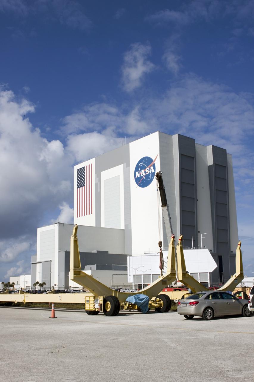
CAPE CANAVERAL, Fla. – At NASA’s Kennedy Space Center in Florida, two space shuttle external fuel tank transporters are being prepared for transfer to the Wings of Dreams Aviation Museum at Keystone Heights Airport between Gainesville and Jacksonville, Fla. At the Wings of Dreams Aviation Museum a mock-up shuttle external fuel tank will be displayed. During space shuttle launches, the external tanks contained over 500,000 gallons of liquid hydrogen and liquid oxygen propellant for the shuttle orbiters' three main engines. The effort is part of Transition and Retirement of the space shuttle. For more information, visit http://www.nasa.gov/transition Photo credit: NASA/ Jim Grossmann
KENNEDY SPACE CENTER, FLA. - Under evening cloud-filled skies, Space Shuttle Discovery remains on the pad two days after the Shuttle’s launch on Return to Flight mission STS-114 was scrubbed. The July 13 mission was scrubbed when a low-level fuel cut-off sensor for the liquid hydrogen tank inside the External Tank failed a routine prelaunch check during the countdown July 13, causing mission managers to scrub Discovery's first launch attempt. The sensor protects the Shuttle's main engines by triggering their shutdown in the event fuel runs unexpectedly low. The sensor is one of four inside the liquid hydrogen section of the External Tank (ET).
KENNEDY SPACE CENTER, FLA. - Viewed from the west side of Launch Pad 39B, the Rotating Service Structure surrounds Space Shuttle Discovery after scrub of Return to Flight mission STS-114. The July 13 mission was scrubbed when a low-level fuel cut-off sensor for the liquid hydrogen tank inside the External Tank failed a routine prelaunch check during the countdown July 13, causing mission managers to scrub Discovery's first launch attempt. The sensor protects the Shuttle's main engines by triggering their shutdown in the event fuel runs unexpectedly low. The sensor is one of four inside the liquid hydrogen section of the External Tank (ET).
CAPE CANAVERAL, Fla. – At NASA’s Kennedy Space Center in Florida, two space shuttle external fuel tank transporters are being prepared for transfer to the Wings of Dreams Aviation Museum at Keystone Heights Airport between Gainesville and Jacksonville, Fla. At the Wings of Dreams Aviation Museum a mock-up shuttle external fuel tank will be displayed. During space shuttle launches, the external tanks contained over 500,000 gallons of liquid hydrogen and liquid oxygen propellant for the shuttle orbiters' three main engines. The effort is part of Transition and Retirement of the space shuttle. For more information, visit http://www.nasa.gov/transition Photo credit: NASA/ Jim Grossmann
CAPE CANAVERAL, Fla. – At NASA’s Kennedy Space Center in Florida, two space shuttle external fuel tank transporters are being prepared for transfer to the Wings of Dreams Aviation Museum at Keystone Heights Airport between Gainesville and Jacksonville, Fla. At the Wings of Dreams Aviation Museum a mock-up shuttle external fuel tank will be displayed. During space shuttle launches, the external tanks contained over 500,000 gallons of liquid hydrogen and liquid oxygen propellant for the shuttle orbiters' three main engines. The effort is part of Transition and Retirement of the space shuttle. For more information, visit http://www.nasa.gov/transition Photo credit: NASA/ Jim Grossmann
KENNEDY SPACE CENTER, FLA. - The gate is open to Launch Pad 39B where Space Shuttle Discovery remains on the pad after scrub of Return to Flight mission STS-114. The July 13 mission was scrubbed when a low-level fuel cut-off sensor for the liquid hydrogen tank inside the External Tank failed a routine prelaunch check during the countdown July 13, causing mission managers to scrub Discovery's first launch attempt. The sensor protects the Shuttle's main engines by triggering their shutdown in the event fuel runs unexpectedly low. The sensor is one of four inside the liquid hydrogen section of the External Tank (ET).
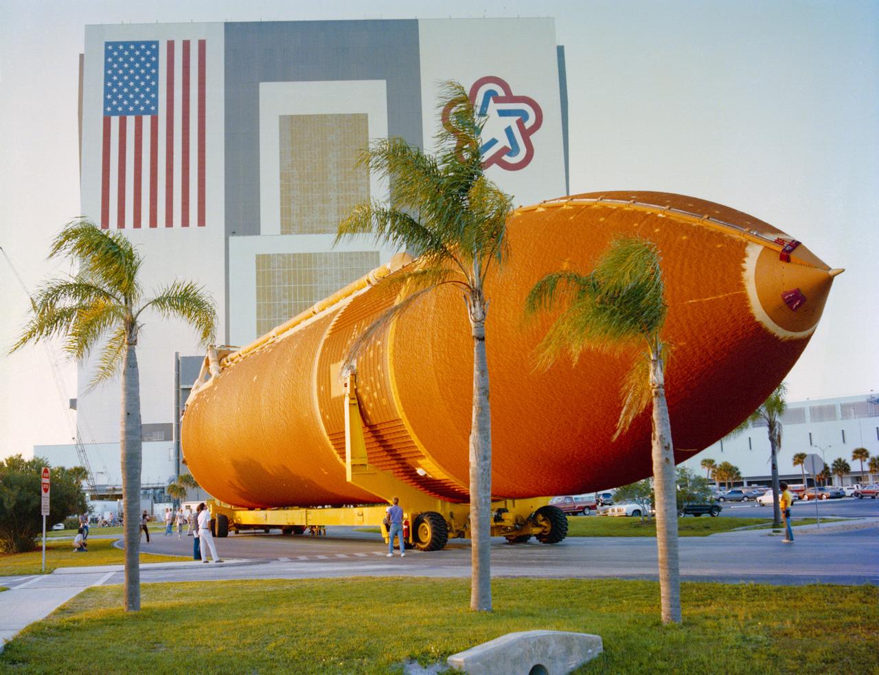
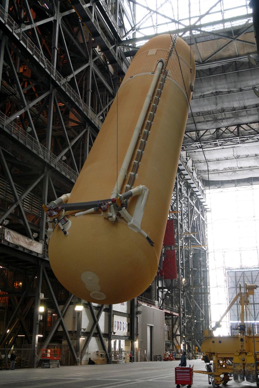
S88-37367 (March 28, 1988) --- The external tank (ET) for STS-27 arrived at Kennedy Space Center (KSC) today via ocean going barge and was moved into the Vehicle Assembly Building (VAB) where preparations will soon begin to ready it for the second return flight launch of the Space Shuttle. The tank is 154 feet long, 27.5 feet in diameter, and holds a total of 1,585,379 pounds of liquid oxygen and liquid hydrogen fuel - fuel which is used by the orbiter's main engines during launch. The empty burnt orange colored tank weighs 1,667,677 pounds and is the only piece of flight hardware not recovered for reuse.
KENNEDY SPACE CENTER, FLA. - Under evening cloud-filled skies, Space Shuttle Discovery remains on the pad two days after the Shuttle’s launch on Return to Flight mission STS-114 was scrubbed. The July 13 mission was scrubbed when a low-level fuel cut-off sensor for the liquid hydrogen tank inside the External Tank failed a routine prelaunch check during the countdown July 13, causing mission managers to scrub Discovery's first launch attempt. The sensor protects the Shuttle's main engines by triggering their shutdown in the event fuel runs unexpectedly low. The sensor is one of four inside the liquid hydrogen section of the External Tank (ET).
KENNEDY SPACE CENTER, FLA. - Space Shuttle Discovery remains on the pad the day after the Shuttle’s launch on Return to Flight mission STS-114 was scrubbed. The July 13 mission was scrubbed when a low-level fuel cut-off sensor for the liquid hydrogen tank inside the External Tank failed a routine prelaunch check during the countdown July 13, causing mission managers to scrub Discovery's first launch attempt. The sensor protects the Shuttle's main engines by triggering their shutdown in the event fuel runs unexpectedly low. The sensor is one of four inside the liquid hydrogen section of the External Tank (ET).
CAPE CANAVERAL, Fla. – At NASA’s Kennedy Space Center in Florida, two space shuttle external fuel tank transporters are being prepared for transfer to the Wings of Dreams Aviation Museum at Keystone Heights Airport between Gainesville and Jacksonville, Fla. At the Wings of Dreams Aviation Museum a mock-up shuttle external fuel tank will be displayed. During space shuttle launches, the external tanks contained over 500,000 gallons of liquid hydrogen and liquid oxygen propellant for the shuttle orbiters' three main engines. The effort is part of Transition and Retirement of the space shuttle. For more information, visit http://www.nasa.gov/transition Photo credit: NASA/ Jim Grossmann
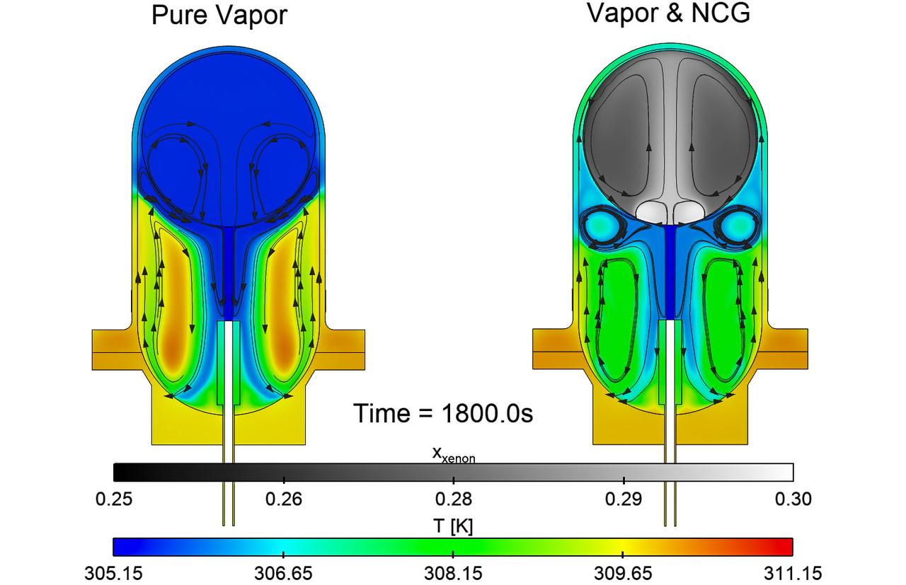
jsc2025e067420 (8/5/2025) --- Simulations of the effects of noncondensable gas on the flow and thermal structures that develop in a fuel tank in microgravity for the ZBOT-NC investigation. On the left, simulation of a tank with pure fluid and on the right, one with a fluid and gas. Credit: Case Western Reserve University
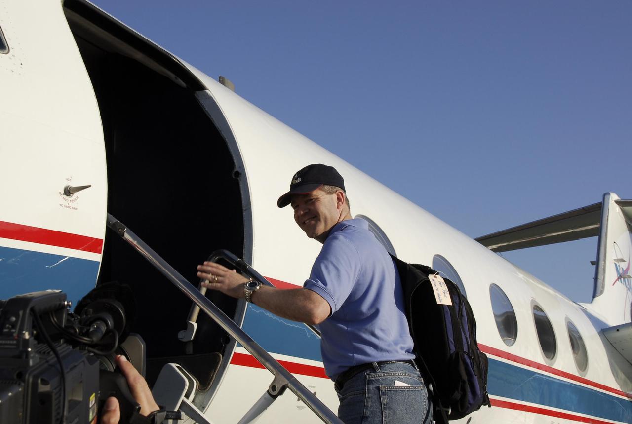
KENNEDY SPACE CENTER, FLA. -- On the Shuttle Landing Facility at NASA's Kennedy Space Center, STS-122 Commander Steve Frick heads for the plane for the return trip to Houston. The crew is flying back to Houston after launch of space shuttle Atlantis was delayed when a failure occurred in a fuel sensor system while the vehicle's external fuel tank was being filled. One of the four engine cutoff, or ECO, sensors inside the liquid hydrogen section of the tank gave a false reading and NASA's current Launch Commit Criteria require that all four sensors function properly. The sensor system is one of several that protect the shuttle's main engines by triggering their shut down if fuel runs unexpectedly low. Space shuttle Atlantis' STS-122 mission now is targeted to launch no earlier than Jan. 2. The liftoff date depends on the resolution of the problem in the fuel sensor system. Photo credit: NASA/Kim Shiflett

KENNEDY SPACE CENTER, FLA. -- On the Shuttle Landing Facility at NASA's Kennedy Space Center, STS-122 Mission Specialist Rex Walheim heads for the plane for the return trip to Houston. The crew is flying back to Houston after launch of space shuttle Atlantis was delayed when a failure occurred in a fuel sensor system while the vehicle's external fuel tank was being filled. One of the four engine cutoff, or ECO, sensors inside the liquid hydrogen section of the tank gave a false reading and NASA's current Launch Commit Criteria require that all four sensors function properly. The sensor system is one of several that protect the shuttle's main engines by triggering their shut down if fuel runs unexpectedly low. Space shuttle Atlantis' STS-122 mission now is targeted to launch no earlier than Jan. 2. The liftoff date depends on the resolution of the problem in the fuel sensor system. Photo credit: NASA/Kim Shiflett

KENNEDY SPACE CENTER, FLA. -- On the Shuttle Landing Facility at NASA's Kennedy Space Center, STS-122 Mission Specialist Leland Melvin heads for the plane for the return trip to Houston. The crew is flying back to Houston after launch of space shuttle Atlantis was delayed when a failure occurred in a fuel sensor system while the vehicle's external fuel tank was being filled. One of the four engine cutoff, or ECO, sensors inside the liquid hydrogen section of the tank gave a false reading and NASA's current Launch Commit Criteria require that all four sensors function properly. The sensor system is one of several that protect the shuttle's main engines by triggering their shut down if fuel runs unexpectedly low. Space shuttle Atlantis' STS-122 mission now is targeted to launch no earlier than Jan. 2. The liftoff date depends on the resolution of the problem in the fuel sensor system. Photo credit: NASA/Kim Shiflett

KENNEDY SPACE CENTER, FLA. -- On the Shuttle Landing Facility at NASA's Kennedy Space Center, the plane carrying the STS-122 crew taxis toward the runway for the return trip to Houston. The crew is flying back to Houston after launch of space shuttle Atlantis was delayed when a failure occurred in a fuel sensor system while the vehicle's external fuel tank was being filled. One of the four engine cutoff, or ECO, sensors inside the liquid hydrogen section of the tank gave a false reading and NASA's current Launch Commit Criteria require that all four sensors function properly. The sensor system is one of several that protect the shuttle's main engines by triggering their shut down if fuel runs unexpectedly low. Space shuttle Atlantis' STS-122 mission now is targeted to launch no earlier than Jan. 2. The liftoff date depends on the resolution of the problem in the fuel sensor system. Photo credit: NASA/Kim Shiflett

KENNEDY SPACE CENTER, FLA. -- On the Shuttle Landing Facility at NASA's Kennedy Space Center, STS-122 Pilot Alan Poindexter heads for the plane for the return trip to Houston. The crew is flying back to Houston after launch of space shuttle Atlantis was delayed when a failure occurred in a fuel sensor system while the vehicle's external fuel tank was being filled. One of the four engine cutoff, or ECO, sensors inside the liquid hydrogen section of the tank gave a false reading and NASA's current Launch Commit Criteria require that all four sensors function properly. The sensor system is one of several that protect the shuttle's main engines by triggering their shut down if fuel runs unexpectedly low. Space shuttle Atlantis' STS-122 mission now is targeted to launch no earlier than Jan. 2. The liftoff date depends on the resolution of the problem in the fuel sensor system. Photo credit: NASA/Kim Shiflett
KENNEDY SPACE CENTER, FLA. -- On the Shuttle Landing Facility at NASA's Kennedy Space Center, STS-122 Mission Specialist Stanley Love heads for the plane for the return trip to Houston. The crew is flying back to Houston after launch of space shuttle Atlantis was delayed when a failure occurred in a fuel sensor system while the vehicle's external fuel tank was being filled. One of the four engine cutoff, or ECO, sensors inside the liquid hydrogen section of the tank gave a false reading and NASA's current Launch Commit Criteria require that all four sensors function properly. The sensor system is one of several that protect the shuttle's main engines by triggering their shut down if fuel runs unexpectedly low. Space shuttle Atlantis' STS-122 mission now is targeted to launch no earlier than Jan. 2. The liftoff date depends on the resolution of the problem in the fuel sensor system. Photo credit: NASA/Kim Shiflett
KENNEDY SPACE CENTER, FLA. - External Tank 118 (ET-118) is lifted from its cell in the Vehicle Assembly Building in order to place it on a transporter. The tank will be transferred to NASA’s Michoud Assembly Facility in New Orleans. The tank is being installed with an improved bipod fitting, which connects the external fuel tank to the Shuttle during launch. The new design, a significant milestone in the effort to return the Shuttle to safe flight, replaces the foam that was used to prevent ice buildup on the tank’s bipod fittings with four rod-shaped heaters. The heaters are being retrofitted on the 11 existing tanks and incorporated into the manufacture of all new tanks.
KENNEDY SPACE CENTER, FLA. - External Tank 118 (ET-118) is lowered from its cell in the Vehicle Assembly Building in order to place it on a transporter. The tank will be transferred to NASA’s Michoud Assembly Facility in New Orleans. The tank is being installed with an improved bipod fitting, which connects the external fuel tank to the Shuttle during launch. The new design, a significant milestone in the effort to return the Shuttle to safe flight, replaces the foam that was used to prevent ice buildup on the tank’s bipod fittings with four rod-shaped heaters. The heaters are being retrofitted on the 11 existing tanks and incorporated into the manufacture of all new tanks.
KENNEDY SPACE CENTER, FLA. - External Tank 118 (ET-118) progresses slowly from the Vehicle Assembly Building, in the background, to the barge in the Turn Basin at Launch Complex 39. The tank will be transported to NASA’s Michoud Assembly Facility in New Orleans. The tank is being installed with an improved bipod fitting, which connects the external fuel tank to the Shuttle during launch. The new design, a significant milestone in the effort to return the Shuttle to safe flight, replaces the foam that was used to prevent ice buildup on the tank’s bipod fittings with four rod-shaped heaters. The heaters are being retrofitted on the 11 existing tanks and incorporated into the manufacture of all new tanks.
KENNEDY SPACE CENTER, FLA. - After being lowered from its cell in the Vehicle Assembly Building, External Tank 118 (ET-118) is suspended above the transfer aisle before being placed on the transporter at left. The tank will be transferred to NASA’s Michoud Assembly Facility in New Orleans. The tank is being installed with an improved bipod fitting, which connects the external fuel tank to the Shuttle during launch. The new design, a significant milestone in the effort to return the Shuttle to safe flight, replaces the foam that was used to prevent ice buildup on the tank’s bipod fittings with four rod-shaped heaters. The heaters are being retrofitted on the 11 existing tanks and incorporated into the manufacture of all new tanks.

KENNEDY SPACE CENTER, FLA. - Workers in the transfer aisle of the Vehicle Assembly Building prepare to lower the External Tank 118 (ET-118) to a horizontal position before being placed on a transporter. The tank will be transferred to NASA’s Michoud Assembly Facility in New Orleans. The tank is being installed with an improved bipod fitting, which connects the external fuel tank to the Shuttle during launch. The new design, a significant milestone in the effort to return the Shuttle to safe flight, replaces the foam that was used to prevent ice buildup on the tank’s bipod fittings with four rod-shaped heaters. The heaters are being retrofitted on the 11 existing tanks and incorporated into the manufacture of all new tanks.
KENNEDY SPACE CENTER, FLA. - External Tank 118 (ET-118) is transferred from the Vehicle Assembly Building to the barge in the Turn Basin at Launch Complex 39. The tank will be transported to NASA’s Michoud Assembly Facility in New Orleans. The tank is being installed with an improved bipod fitting, which connects the external fuel tank to the Shuttle during launch. The new design, a significant milestone in the effort to return the Shuttle to safe flight, replaces the foam that was used to prevent ice buildup on the tank’s bipod fittings with four rod-shaped heaters. The heaters are being retrofitted on the 11 existing tanks and incorporated into the manufacture of all new tanks.
KENNEDY SPACE CENTER, FLA. - KSC workers escort External Tank 118 (ET-118) from the Vehicle Assembly Building, in the background, to the barge in the Turn Basin at Launch Complex 39. The tank will be transported to NASA’s Michoud Assembly Facility in New Orleans. The tank is being installed with an improved bipod fitting, which connects the external fuel tank to the Shuttle during launch. The new design, a significant milestone in the effort to return the Shuttle to safe flight, replaces the foam that was used to prevent ice buildup on the tank’s bipod fittings with four rod-shaped heaters. The heaters are being retrofitted on the 11 existing tanks and incorporated into the manufacture of all new tanks.
KENNEDY SPACE CENTER, FLA. - Workers in the transfer aisle of the Vehicle Assembly Building check the progress of External Tank 118 (ET-118) as it is lowered onto the transporter below it. The tank will be transferred to NASA’s Michoud Assembly Facility in New Orleans. The tank is being installed with an improved bipod fitting, which connects the external fuel tank to the Shuttle during launch. The new design, a significant milestone in the effort to return the Shuttle to safe flight, replaces the foam that was used to prevent ice buildup on the tank’s bipod fittings with four rod-shaped heaters. The heaters are being retrofitted on the 11 existing tanks and incorporated into the manufacture of all new tanks.
KENNEDY SPACE CENTER, FLA. - External Tank 118 (ET-118) moves from the Vehicle Assembly Building, in the background, toward the barge in the Turn Basin at Launch Complex 39. The tank will be transported to NASA’s Michoud Assembly Facility in New Orleans. The tank is being installed with an improved bipod fitting, which connects the external fuel tank to the Shuttle during launch. The new design, a significant milestone in the effort to return the Shuttle to safe flight, replaces the foam that was used to prevent ice buildup on the tank’s bipod fittings with four rod-shaped heaters. The heaters are being retrofitted on the 11 existing tanks and incorporated into the manufacture of all new tanks.
KENNEDY SPACE CENTER, FLA. - External Tank 118 (ET-118) is slowly moved above the transporter in the transfer aisle of the Vehicle Assembly Building before being lowered. The tank will be transferred to NASA’s Michoud Assembly Facility in New Orleans. The tank is being installed with an improved bipod fitting, which connects the external fuel tank to the Shuttle during launch. The new design, a significant milestone in the effort to return the Shuttle to safe flight, replaces the foam that was used to prevent ice buildup on the tank’s bipod fittings with four rod-shaped heaters. The heaters are being retrofitted on the 11 existing tanks and incorporated into the manufacture of all new tanks.
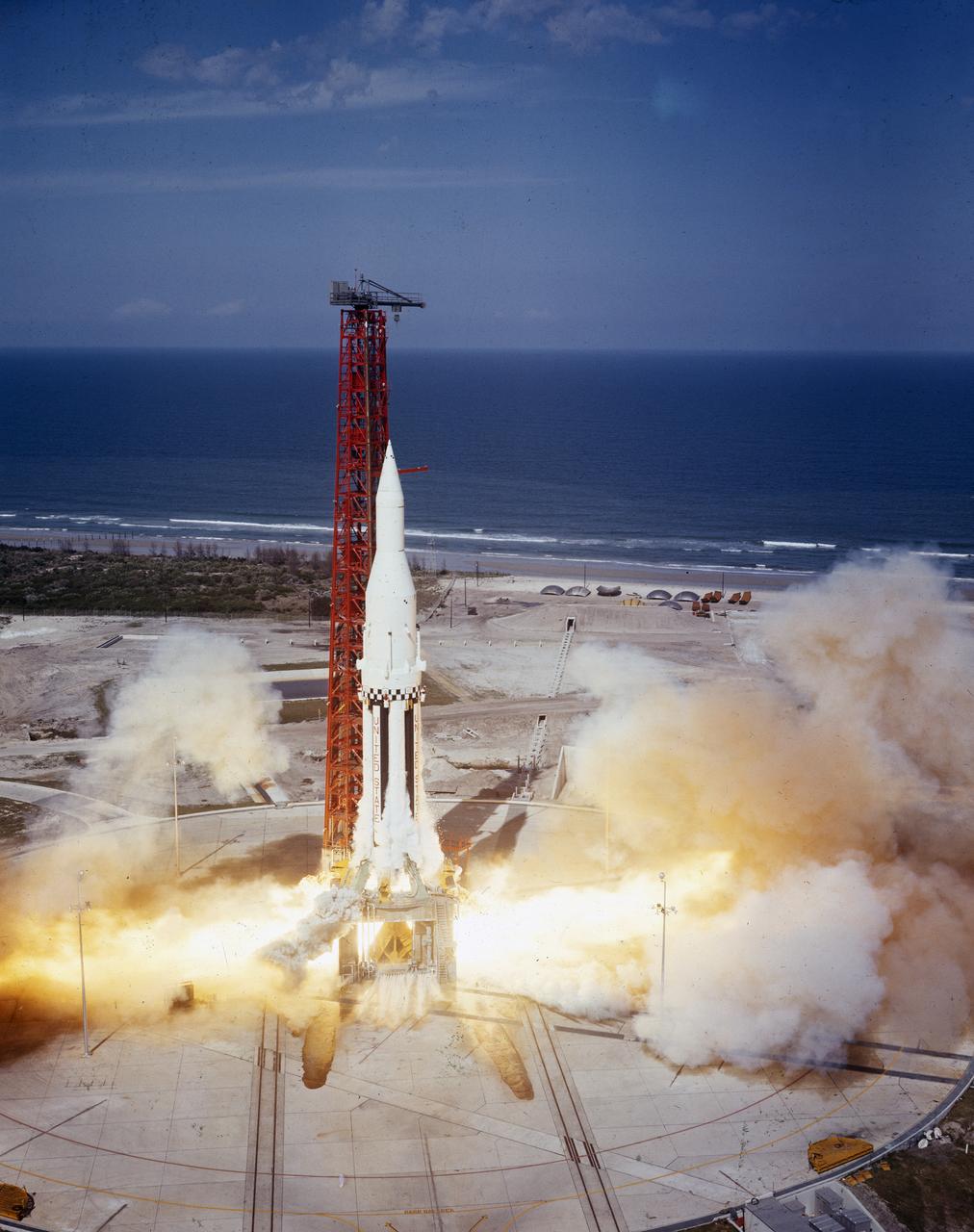
The Saturn I (SA-4) flight lifted off from Kennedy Space Center launch Complex 34, March 28, 1963. The fourth launch of Saturn launch vehicles developed at the Marshall Space Flight Center (MSFC), under the direction of Dr. Wernher von Braun, incorporated a Saturn I, Block I engine. The typical height of a Block I vehicle was approximately 163 feet and had only one live stage. It consisted of eight tanks, each 70 inches in diameter, clustered around a central tank, 105 inches in diameter. Four of the external tanks were fuel tanks for the RP-1 (kerosene) fuel. The other four, spaced alternately with the fuel tanks, were liquid oxygen tanks as was the large center tank. All fuel tanks and liquid oxygen tanks drained at the same rates respectively. The thrust for the stage came from eight H-1 engines, each producing a thrust of 165,000 pounds, for a total thrust of over 1,300,000 pounds. The engines were arranged in a double pattern. Four engines, located inboard, were fixed in a square pattern around the stage axis and canted outward slightly, while the remaining four engines were located outboard in a larger square pattern offset 40 degrees from the inner pattern. Unlike the inner engines, each outer engine was gimbaled. That is, each could be swung through an arc. They were gimbaled as a means of steering the rocket, by letting the instrumentation of the rocket correct any deviations of its powered trajectory. The block I required engine gimabling as the only method of guiding and stabilizing the rocket through the lower atmosphere. The upper stages of the Block I rocket reflected the three-stage configuration of the Saturn I vehicle. Like SA-3, the SA-4 flight’s upper stage ejected 113,560 liters (30,000 gallons) of ballast water in the upper atmosphere for "Project Highwater" physics experiment. Release of this vast quantity of water in a near-space environment marked the second purely scientific large-scale experiment. The SA-4 was the last Block I rocket launch.
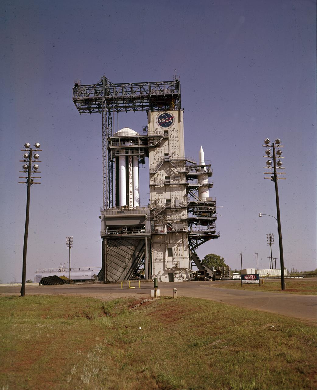
On October 27, 1961, the Marshall Space Flight Center (MSFC) and the Nation marked a high point in the 3-year-old Saturn development program when the first Saturn vehicle flew a flawless 215-mile ballistic trajectory from Cape Canaveral, Florida. SA-1 is pictured here, five months before launch, in the MSFC test stand on May 16, 1961. Developed and tested at MSFC under the direction of Dr. Wernher von Braun, SA-1 incorporated a Saturn I, Block I engine. The typical height of a Block I vehicle was approximately 163 feet. and had only one live stage. It consisted of eight tanks, each 70 inches in diameter, clustered around a central tank, 105 inches in diameter. Four of the external tanks were fuel tanks for the RP-1 (kerosene) fuel. The other four, spaced alternately with the fuel tanks, were liquid oxygen tanks, as was the large center tank. All fuel tanks and liquid oxygen tanks drained at the same rates respectively. The thrust for the stage came from eight H-1 engines, each producing a thrust of 165,000 pounds, for a total thrust of over 1,300,000 pounds. The engines were arranged in a double pattern. Four engines, located inboard, were fixed in a square pattern around the stage axis and canted outward slightly, while the remaining four engines were located outboard in a larger square pattern offset 40 degrees from the inner pattern. Unlike the inner engines, each outer engine was gimbaled. That is, each could be swung through an arc. They were gimbaled as a means of steering the rocket, by letting the instrumentation of the rocket correct any deviations of its powered trajectory. The block I required engine gimabling as the only method of guiding and stabilizing the rocket through the lower atmosphere. The upper stages of the Block I rocket reflected the three-stage configuration of the Saturn I vehicle.
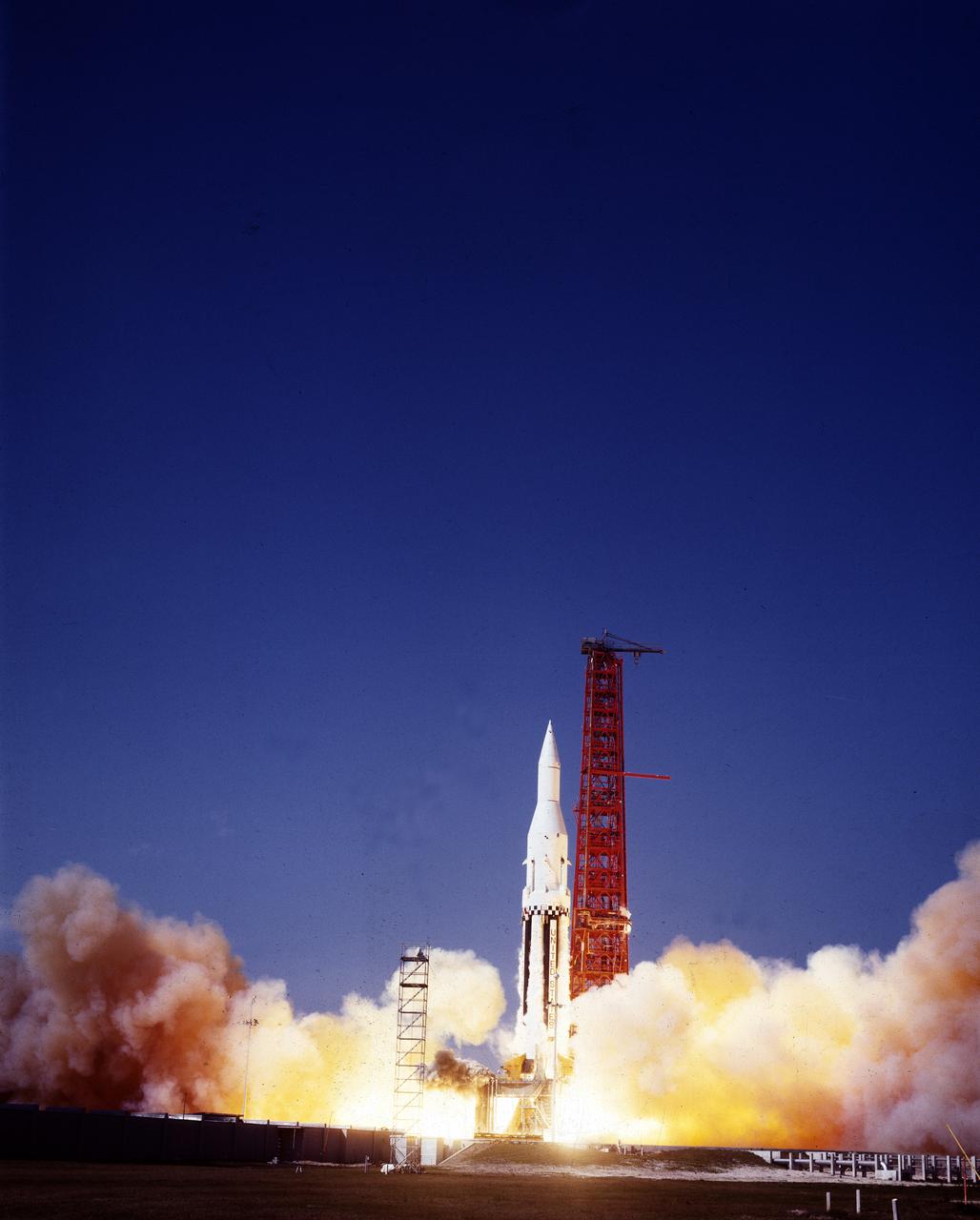
The Saturn I (SA-4) flight lifted off from Kennedy Space Center launch Complex 34, March 28, 1963. The fourth launch of Saturn launch vehicles, developed at the Marshall Space Flight Center (MSFC) under the direction of Dr. Wernher von Braun, incorporated a Saturn I, Block I engine. The typical height of a Block I vehicle was approximately 163 feet and had only one live stage. It consisted of eight tanks, each 70 inches in diameter, clustered around a central tank, 105 inches in diameter. Four of the external tanks were fuel tanks for the RP-1 (kerosene) fuel. The other four, spaced alternately with the fuel tanks, were liquid oxygen tanks as was the large center tank. All fuel tanks and liquid oxygen tanks drained at the same rates respectively. The thrust for the stage came from eight H-1 engines, each producing a thrust of 165,000 pounds, for a total thrust of over 1,300,000 pounds. The engines were arranged in a double pattern. Four engines, located inboard, were fixed in a square pattern around the stage axis and canted outward slightly, while the remaining four engines were located outboard in a larger square pattern offset 40 degrees from the inner pattern. Unlike the inner engines, each outer engine was gimbaled. That is, each could be swung through an arc. They were gimbaled as a means of steering the rocket, by letting the instrumentation of the rocket correct any deviations of its powered trajectory. The block I required engine gimabling as the only method of guiding and stabilizing the rocket through the lower atmosphere. The upper stages of the Block I rocket reflected the three-stage configuration of the Saturn I vehicle. Like SA-3, the SA-4 flight’s upper stage ejected 113,560 liters (30,000 gallons) of ballast water in the upper atmosphere for "Project Highwater" physics experiment. Release of this vast quantity of water in a near-space environment marked the second purely scientific large-scale experiment. The SA-4 was the last Block I rocket launch.
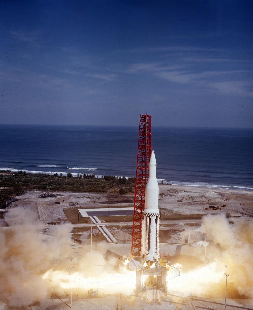
The Saturn I (SA-3) flight lifted off from Kennedy Space Center launch Complex 34, November 16, 1962. The third launch of Saturn launch vehicles, developed at the Marshall Space Flight Center (MSFC) under the direction of Dr. Wernher von Braun, incorporated a Saturn I, Block I engine. The typical height of a Block I vehicle was approximately 163 feet. and had only one live stage. It consisted of eight tanks, each 70 inches in diameter, clustered around a central tank, 105 inches in diameter. Four of the external tanks were fuel tanks for the RP-1 (kerosene) fuel. The other four, spaced alternately with the fuel tanks, were liquid oxygen tanks as was the large center tank. All fuel tanks and liquid oxygen tanks drained at the same rates respectively. The thrust for the stage came from eight H-1 engines, each producing a thrust of 165,000 pounds, for a total thrust of over 1,300,000 pounds. The engines were arranged in a double pattern. Four engines, located inboard, were fixed in a square pattern around the stage axis and canted outward slightly, while the remaining four engines were located outboard in a larger square pattern offset 40 degrees from the inner pattern. Unlike the inner engines, each outer engine was gimbaled. That is, each could be swung through an arc. They were gimbaled as a means of steering the rocket, by letting the instrumentation of the rocket correct any deviations of its powered trajectory. The block I required engine gimabling as the only method of guiding and stabilizing the rocket through the lower atmosphere. The upper stages of the Block I rocket reflected the three-stage configuration of the Saturn I vehicle. During the SA-3 flight, the upper stage ejected 113,560 liters (30,000 gallons) of ballast water in the upper atmosphere for "Project Highwater" physics experiment. The water was released at an altitude of 65 miles, where within only 5 seconds, it expanded into a massive ice cloud 4.6 miles in diameter. Release of this vast quantity of water in a near-space environment marked the first purely scientific large-scale experiment.
KENNEDY SPACE CENTER, FLA. -- Shadows spill across space shuttle Atlantis, still poised on the pad after its launch on mission STS-122 was postponed Thursday. In the background is the Atlantic Ocean. Shuttle program managers decided at 9:56 a.m. to postpone the launch because of an issue with a fuel cut-off sensor system inside the external fuel tank. This is one of several systems that protect the shuttle's main engines by triggering their shut down if fuel runs unexpectedly low. During countdown activities this morning, two sensors failed a routine prelaunch check. There are four engine cut-off, or ECO, sensors inside the liquid hydrogen section of the tank, and Launch Commit Criteria require three of the four sensor systems to be functioning properly. The tank's liquid oxygen and liquid hydrogen was drained from the tank, and preparations will begin for a possible launch attempt Friday. NASA's launch rules have a preplanned procedure that states in the case of ECO sensor system failure, engineers need to drain the tank and verify all the sensors are working as they go dry. Atlantis carries the Columbus Laboratory, the European Space Agency's largest contribution to the construction of the space station. When permanently attached to Node 2, the laboratory will carry out experiments in materials science, fluid physics and biosciences, as well as perform a number of technological applications, in a microgravity environment. Photo credit: NASA/George Shelton
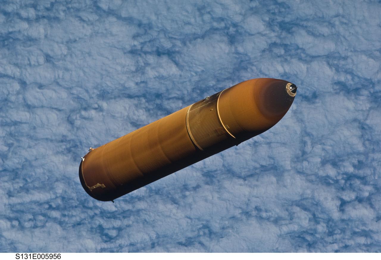
S131-E-005956 (5 April 2010) --- Backdropped by a cloud-covered part of Earth, the STS-131 external fuel tank (ET) begins its relative separation from the Space Shuttle Discovery following launch.
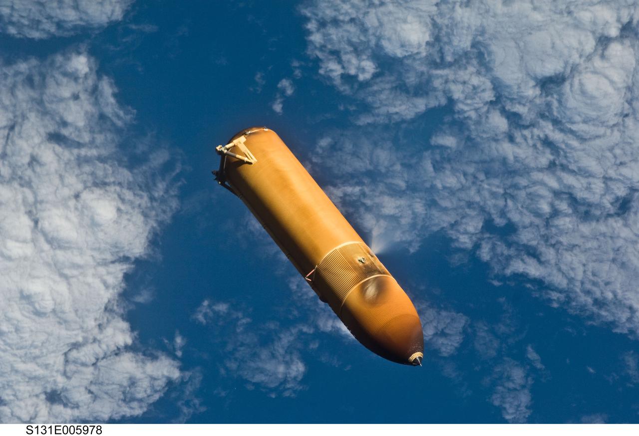
S131-E-005978 (5 April 2010) --- Backdropped by a blue and white part of Earth, the STS-131 external fuel tank (ET) begins its relative separation from the Space Shuttle Discovery following launch.
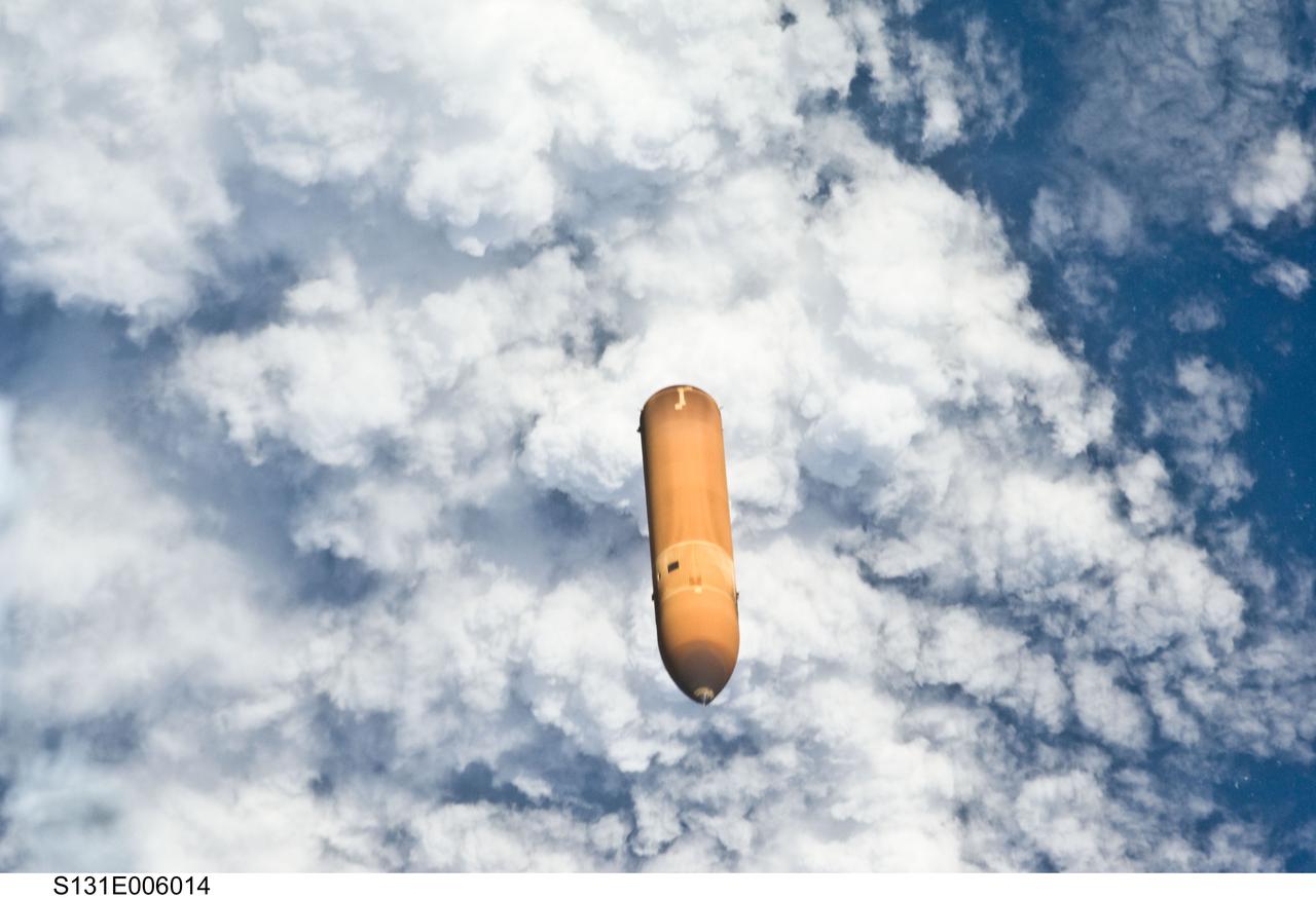
S131-E-006014 (5 April 2010) --- Backdropped by a cloud-covered part of Earth, the STS-131 external fuel tank (ET) begins its relative separation from the Space Shuttle Discovery following launch.
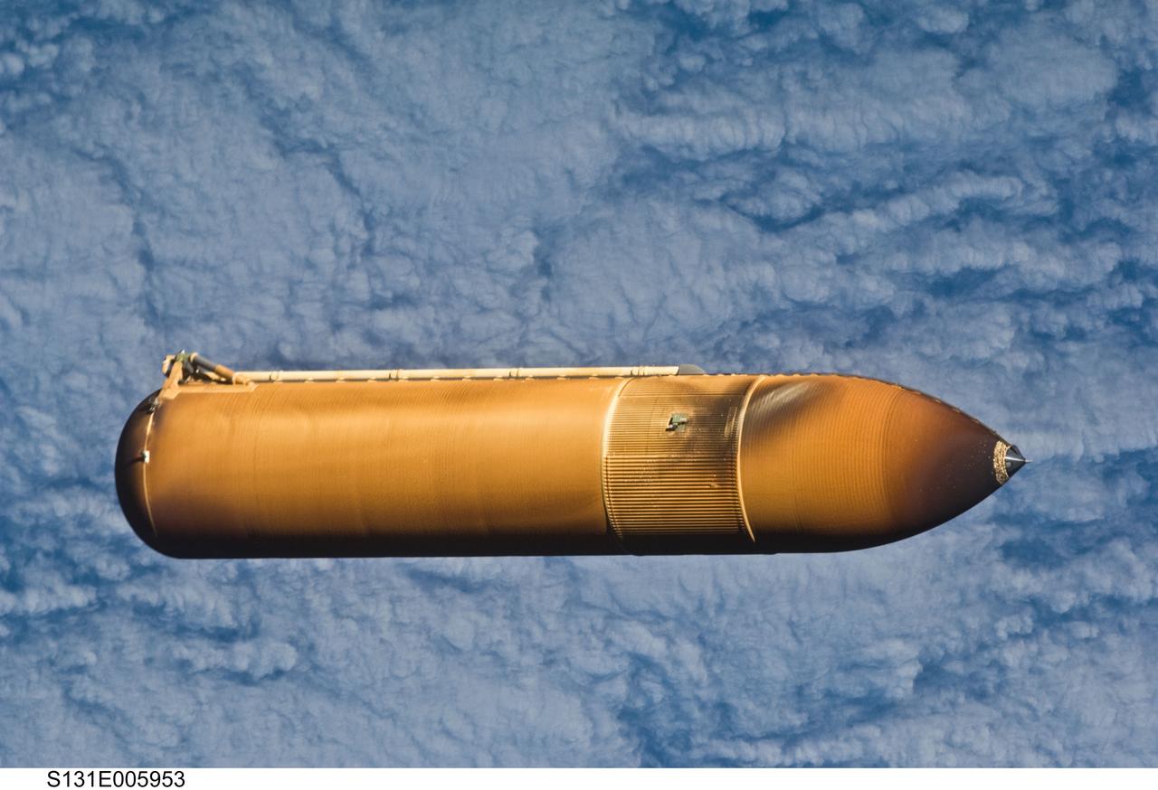
S131-E-005953 (5 April 2010) --- Backdropped by a cloud-covered part of Earth, the STS-131 external fuel tank (ET) begins its relative separation from the Space Shuttle Discovery following launch.
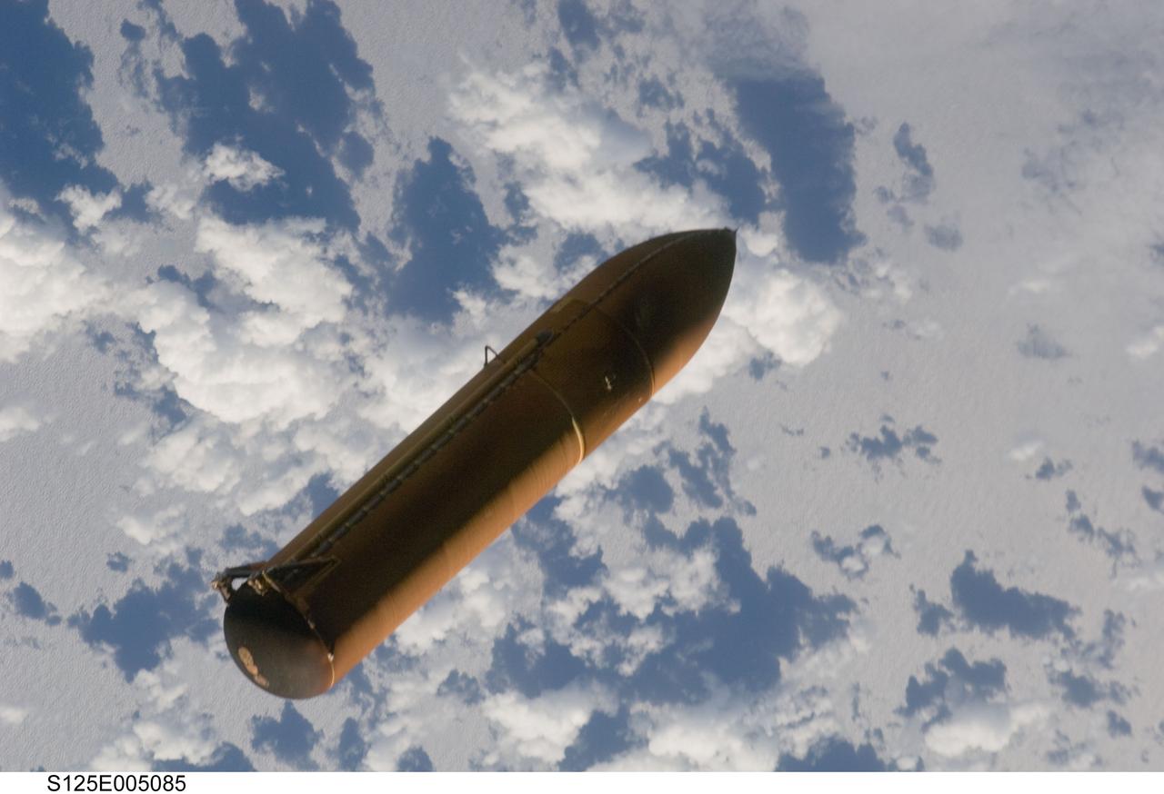
S125-E-005085 (11 May 2009) --- Backdropped by a blue and white part of Earth, the STS-125 external fuel tank (ET) begins its relative separation from the Space Shuttle Atlantis following launch.
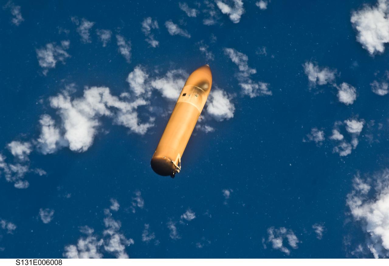
S131-E-006008 (5 April 2010) --- Backdropped by a blue and white part of Earth, the STS-131 external fuel tank (ET) begins its relative separation from the Space Shuttle Discovery following launch.
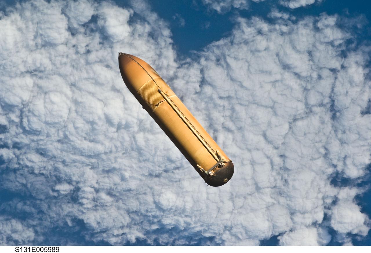
S131-E-005989 (5 April 2010) --- Backdropped by a blue and white part of Earth, the STS-131 external fuel tank (ET) begins its relative separation from the Space Shuttle Discovery following launch.