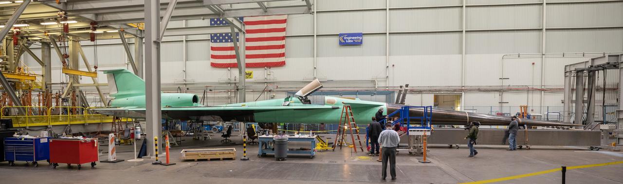
The X-59 sits in the fuel barn at Lockheed Martin in Fort Worth, Texas. While in the fuel barn, the X-59 underwent fuel tank calibration tests. During this phase, the X-59’s gas tanks were filled and fuel-remaining sensors inside the aircraft were checked.
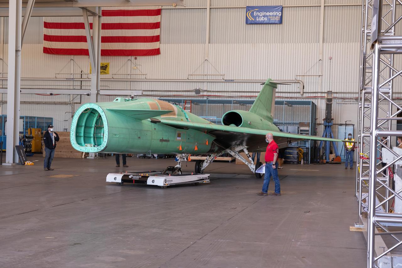
The X-59 is transported to the fuel barn at Lockheed Martin in Fort Worth, Texas to undergo fuel tank calibration tests. During this phase, the X-59’s gas tanks were filled and fuel-remaining sensors inside the aircraft were checked.
The X-59 is transported to the fuel barn at Lockheed Martin in Fort Worth, Texas to undergo fuel tank calibration tests. During this phase, the X-59’s gas tanks were filled and fuel-remaining sensors inside the aircraft were checked.
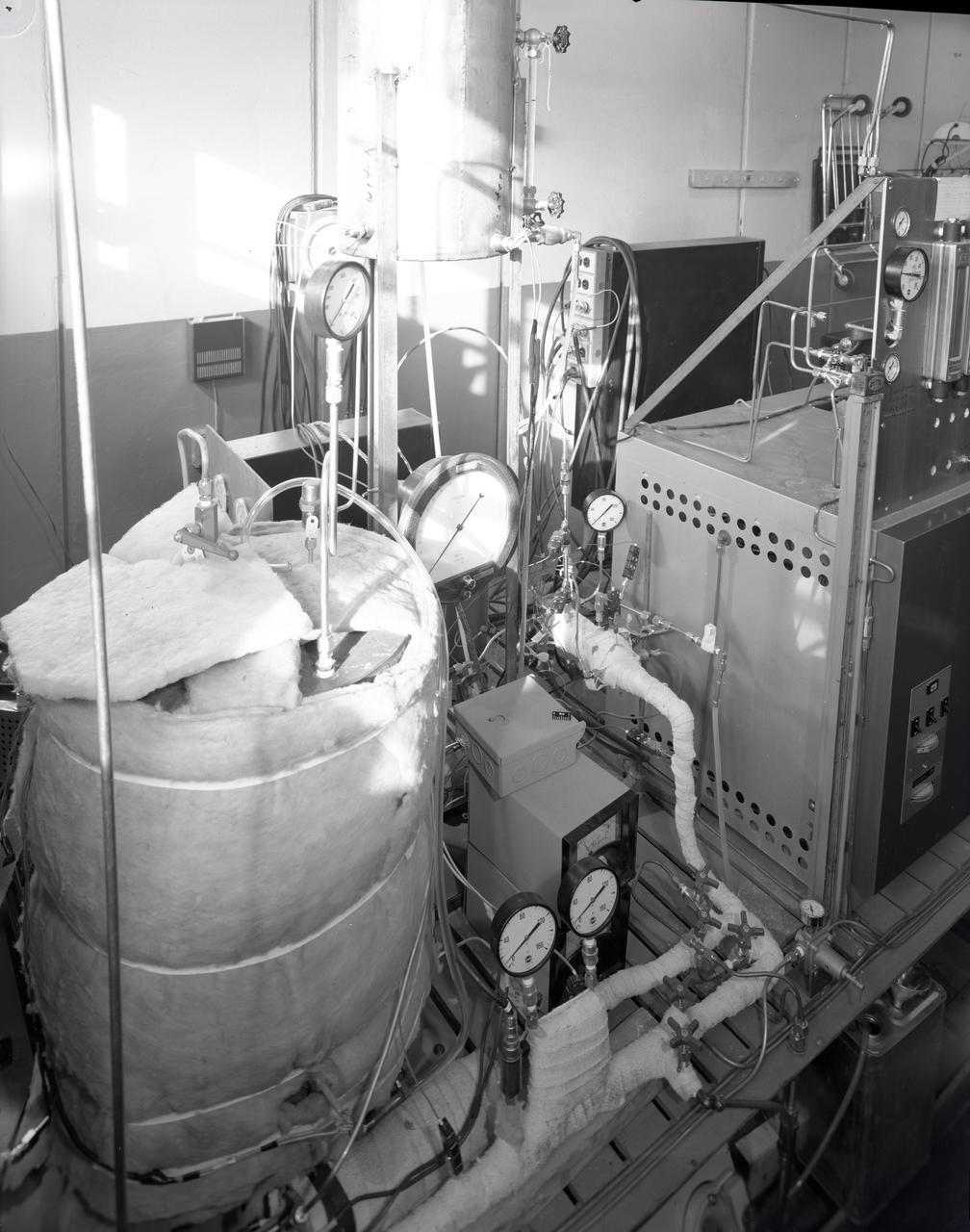
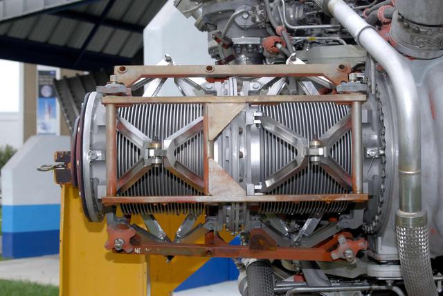
FUEL CELL CONDENSER FOR THE APOLLO SYSTEM TEST RIG
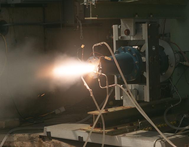
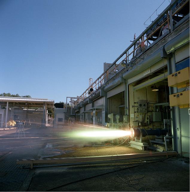
Solid fuel test performed on the Fastrac II engine cell at Marshall's Test Stand 116.
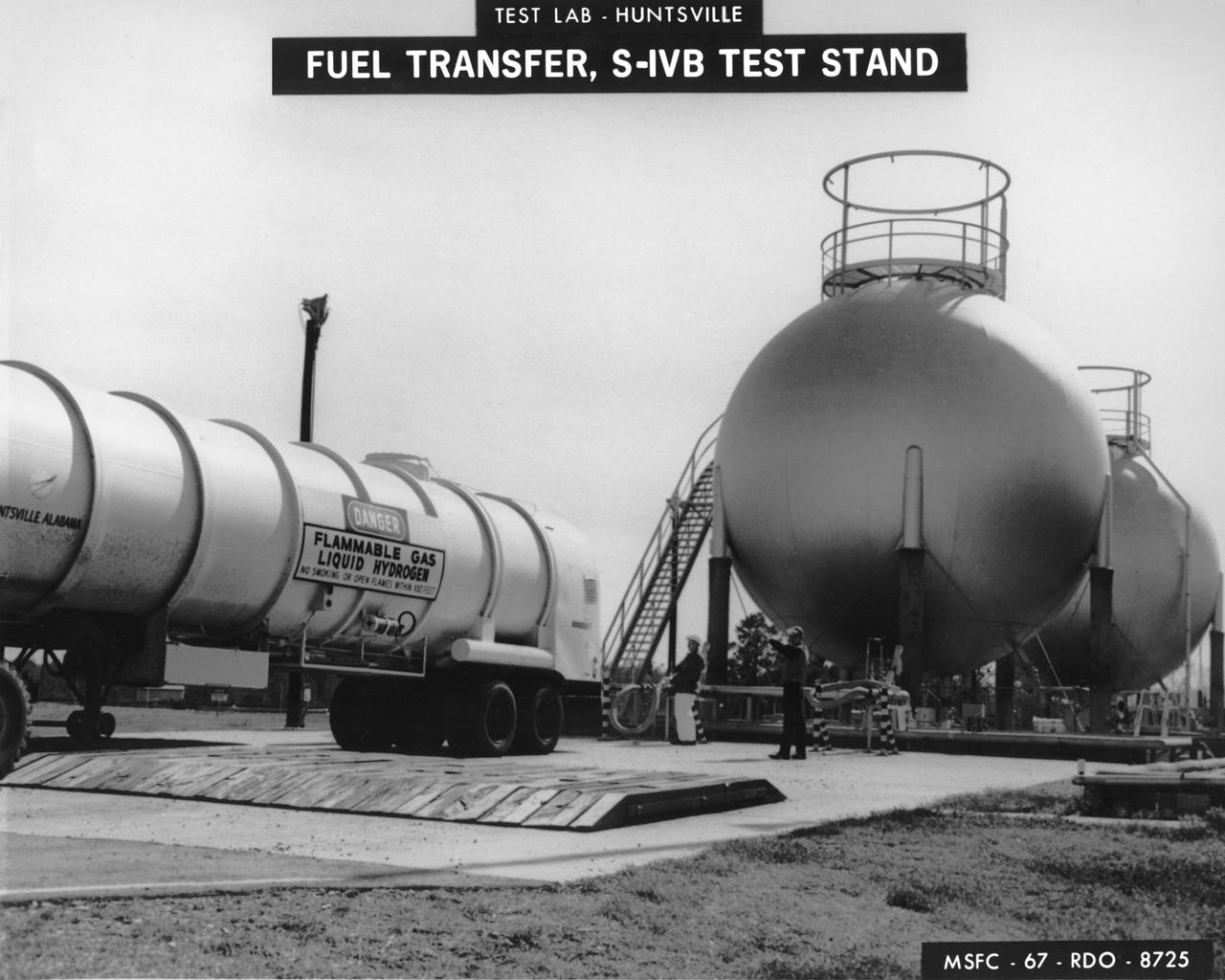
Marshall Space Flight Center (MSFC) workers fill fuel tanks with liquid hydrogen used for test firing at the S-IVB (Dynamic) Test Stand.
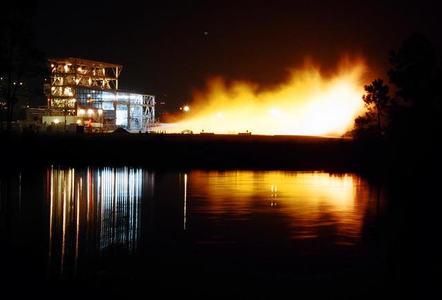
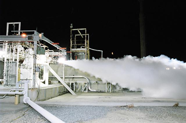
Gaseous hydrogen is burned off at the E1 Test Stand the night of Oct. 7 during a cold-flow test of the fuel turbopump of the Integrated Powerhead Demonstrator (IPD) at NASA Stennis Space Center (SSC). The gaseous hydrogen spins the pump's turbine during the test, which was conducted to verify the pump's performance. Engineers plan one more test before sending the pump to The Boeing Co. for inspection. It will then be returned to SSC for engine system assembly. The IPD is the first reusable hydrogen-fueled advanced engine in development since the Space Shuttle Main Engine.
Fuel Boiling Convection Experiment, FBCE Mission Sequence Test
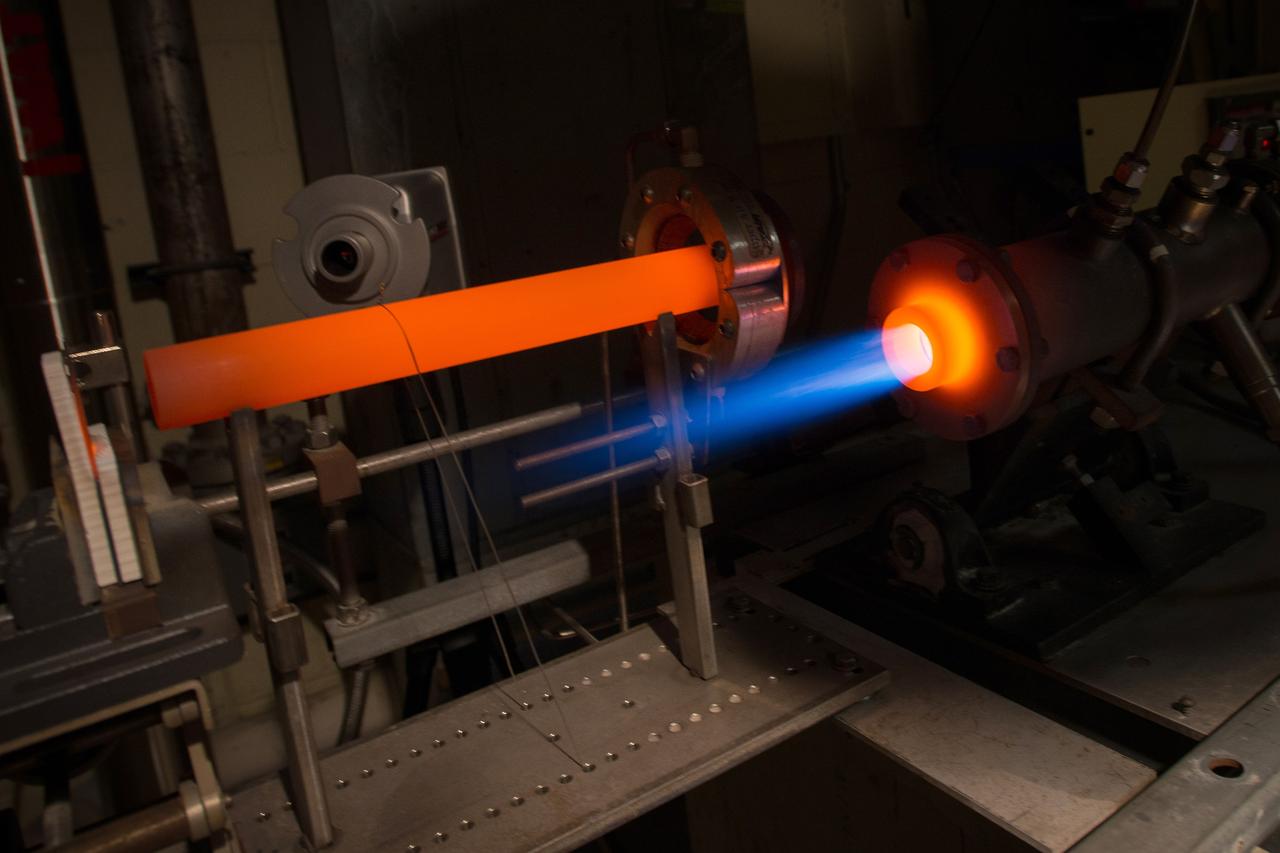
The Fuel Burner Rig is a test laboratory at NASA Glenn, which subjects new jet engine materials, treated with protective coatings, to the hostile, high temperature, high velocity environment found inside aircraft turbine engines. These samples face 200-mile per hour flames to simulate the temperatures of aircraft engines in flight. The rig can also simulate aircraft carrier and dusty desert operations where salt and sand can greatly reduce engine life and performance.
NASA Stennis Space Center engineers conducted a successful cold-flow test of an RS-84 engine component Sept. 24. The RS-84 is a reusable engine fueled by rocket propellant - a special blend of kerosene - designed to power future flight vehicles. Liquid oxygen was blown through the RS-84 subscale preburner to characterize the test facility's performance and the hardware's resistance. Engineers are now moving into the next phase, hot-fire testing, which is expected to continue into February 2004. The RS-84 engine prototype, developed by the Rocketdyne Propulsion and Power division of The Boeing Co. of Canoga Park, Calif., is one of two competing Rocket Engine Prototype technologies - a key element of NASA's Next Generation Launch Technology program.
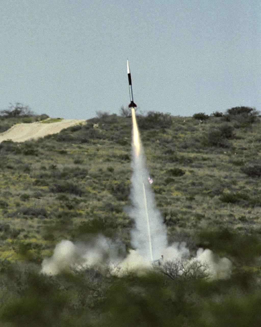
Launch of the first Dryden Aerospike rocket. The Dryden Aerospike Rocket Test provided the first known data from a solid-fueled aerospike rocket in flight.
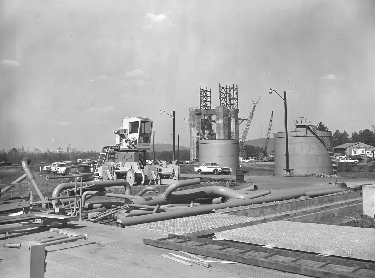
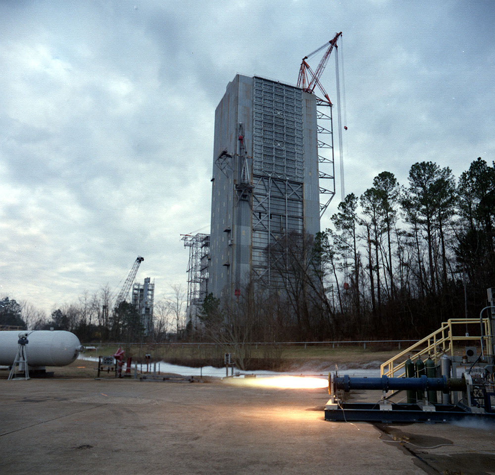
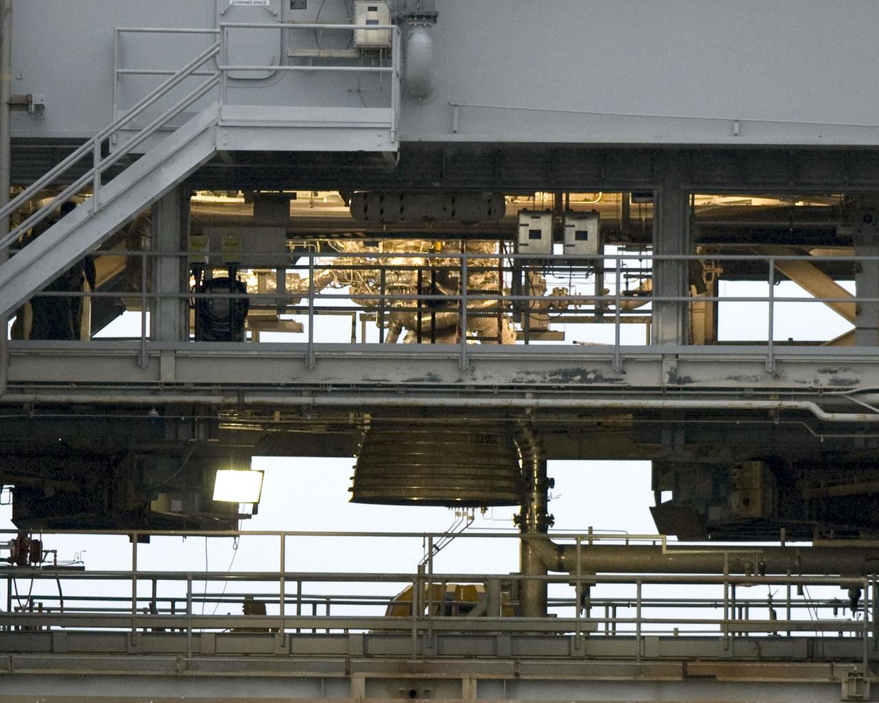
At its founding, the Marshall Space Flight Center (MSFC) inherited the Army’s Jupiter and Redstone test stands, but much larger facilities were needed for the giant stages of the Saturn V. From 1960 to 1964, the existing stands were remodeled and a sizable new test area was developed. The new comprehensive test complex for propulsion and structural dynamics was unique within the nation and the free world, and they remain so today because they were constructed with foresight to meet the future as well as on going needs. Construction of the S-IC Static test stand complex began in 1961 in the west test area of MSFC, and was completed in 1964. The S-IC static test stand was designed to develop and test the 138-ft long and 33-ft diameter Saturn V S-IC first stage, or booster stage, weighing in at 280,000 pounds. Required to hold down the brute force of a 7,500,000-pound thrust produced by 5 F-1 engines, the S-IC static test stand was designed and constructed with the strength of hundreds of tons of steel and 12,000,000 pounds of cement, planted down to bedrock 40 feet below ground level. The foundation walls, constructed with concrete and steel, are 4 feet thick. The base structure consists of four towers with 40-foot-thick walls extending upward 144 feet above ground level. The structure was topped by a crane with a 135-foot boom. With the boom in the upright position, the stand was given an overall height of 405 feet, placing it among the highest structures in Alabama at the time. In addition to the stand itself, related facilities were constructed during this time. Northeast of the massive S-IC test stand, the F-1 Engine test stand was built. The F-1 test stand is a vertical engine firing test stand, 239 feet in elevation and 4,600 square feet in area at the base, and was designed to assist in the development of the F-1 Engine. Capability was provided for static firing of 1.5 million pounds of thrust using liquid oxygen and kerosene. Like the S-IC stand, the foundation of the F-1 stand is keyed into the bedrock approximately 40 feet below grade. This photo depicts the fuel tanks that housed kerosene and just beyond those is the F-1 test stand.
Stennis Space Center engineers are preparing to conduct water tests on an updated version of the scissors duct component of the J-2X engine. Measuring about 2 feet long and about 8 inches in diameter, the duct on the J-2X predecessor, the J-2, connected its fuel turbo pumps to the flight vehicle's upper stage run tanks. According to NASA's J-2X project manager at SSC, Gary Benton, the water tests should establish the limits of the duct's ability to withstand vibration.
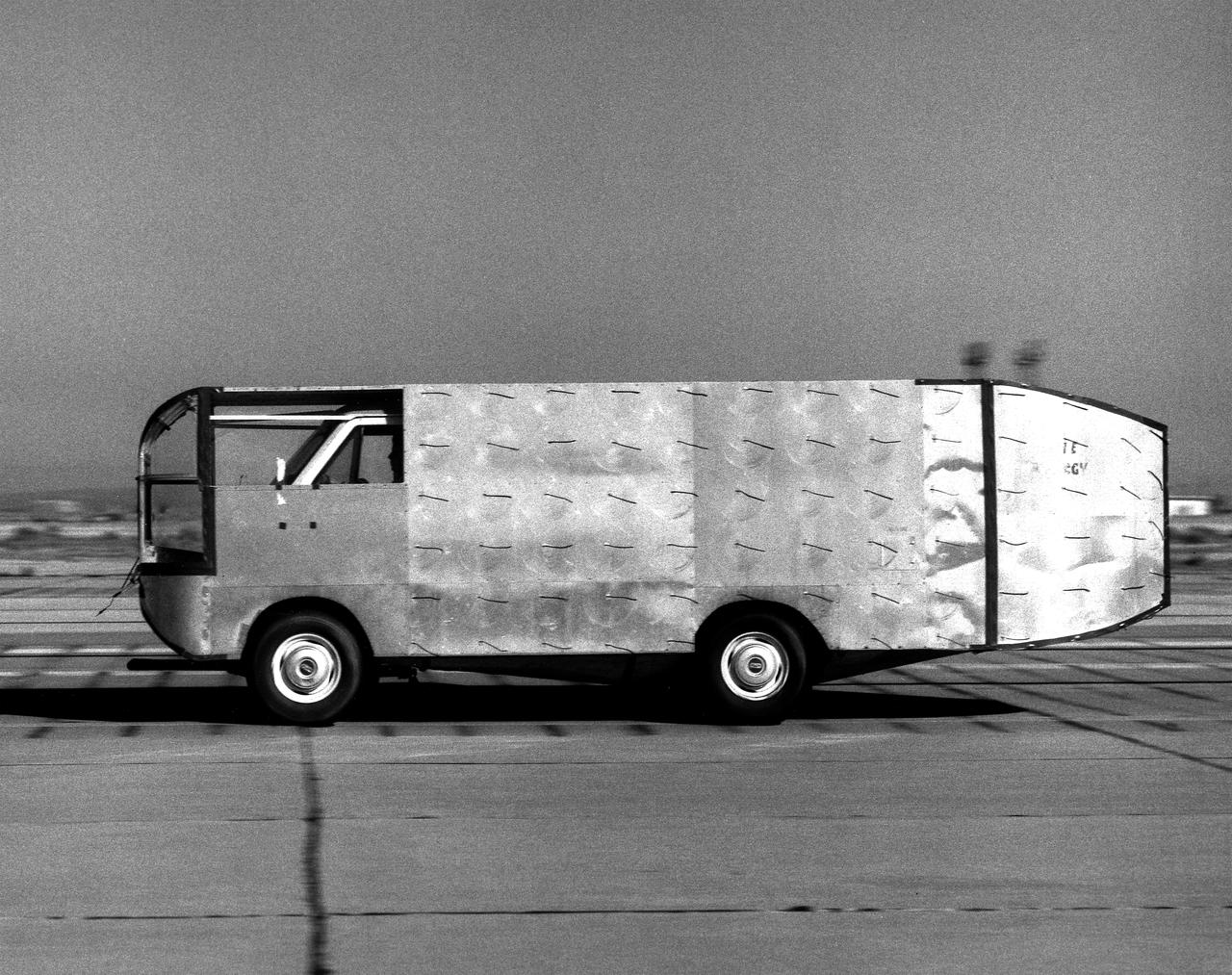
Air flow testing on aerodynamic truck
BOEING HIGH CAPACITY FUEL TANK BEING READIED FOR PLACEMENT ON WEST TEST AREA TEST STAND IN ANTICIPATION OF FURTHER TESTING.
BOEING HIGH CAPACITY FUEL TANK BEING READIED FOR PLACEMENT ON WEST TEST AREA TEST STAND IN ANTICIPATION OF FURTHER TESTING.
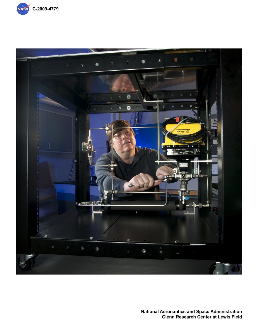
Common Test Bed, Fuel Cell Laboratory
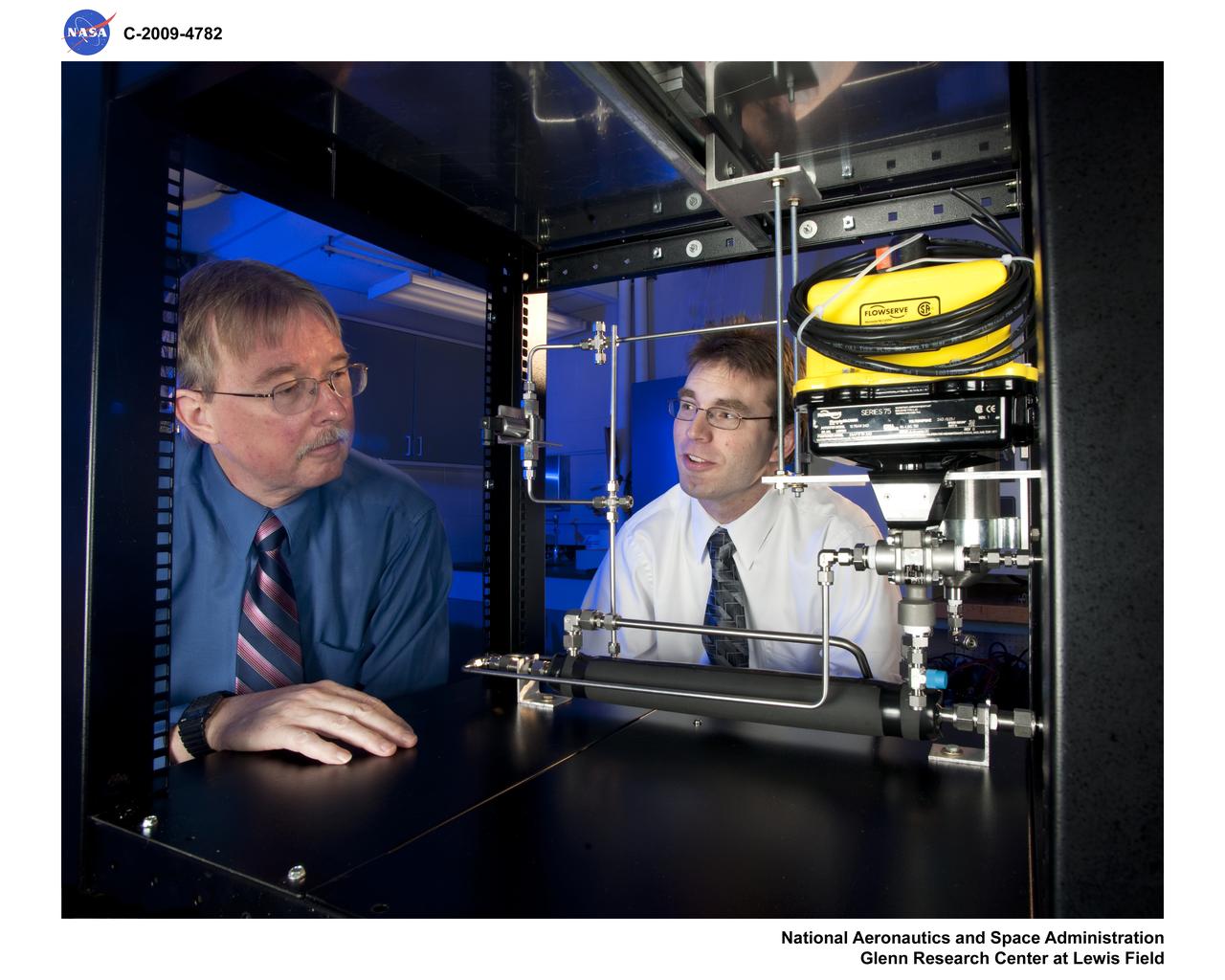
Common Test Bed, Fuel Cell Laboratory
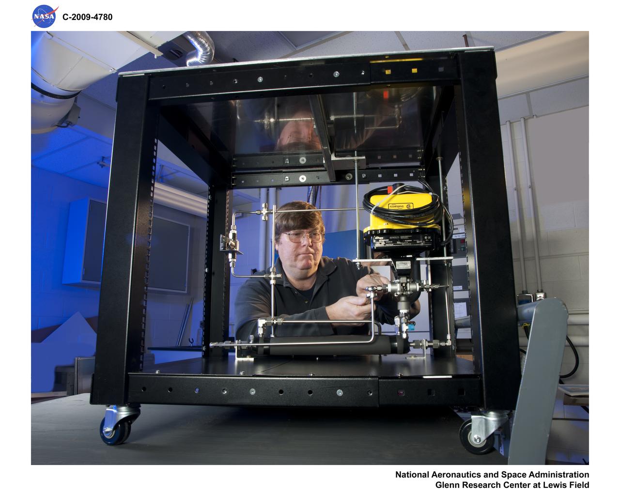
Common Test Bed, Fuel Cell Laboratory
An 11 inch (11) hybrid motor fuel grain variation test firing at Marshall's Test Stand 500.
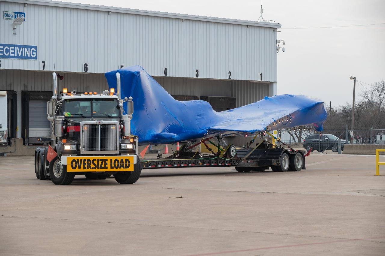
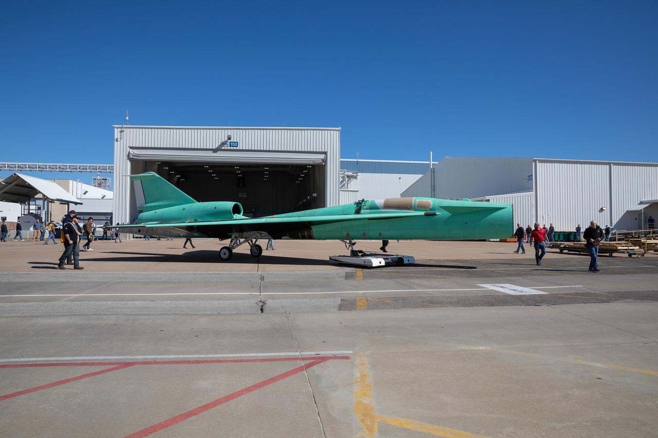
The X-59 arrives in Fort Worth, Texas from Palmdale, California, ready to undergo some important structural and fuel tests at the Lockheed Martin facility. The bright blue wrap around the X-plane is a precautionary measure to keep the exterior of the X-59 safe as it traveled through multiple states on its way to Texas.
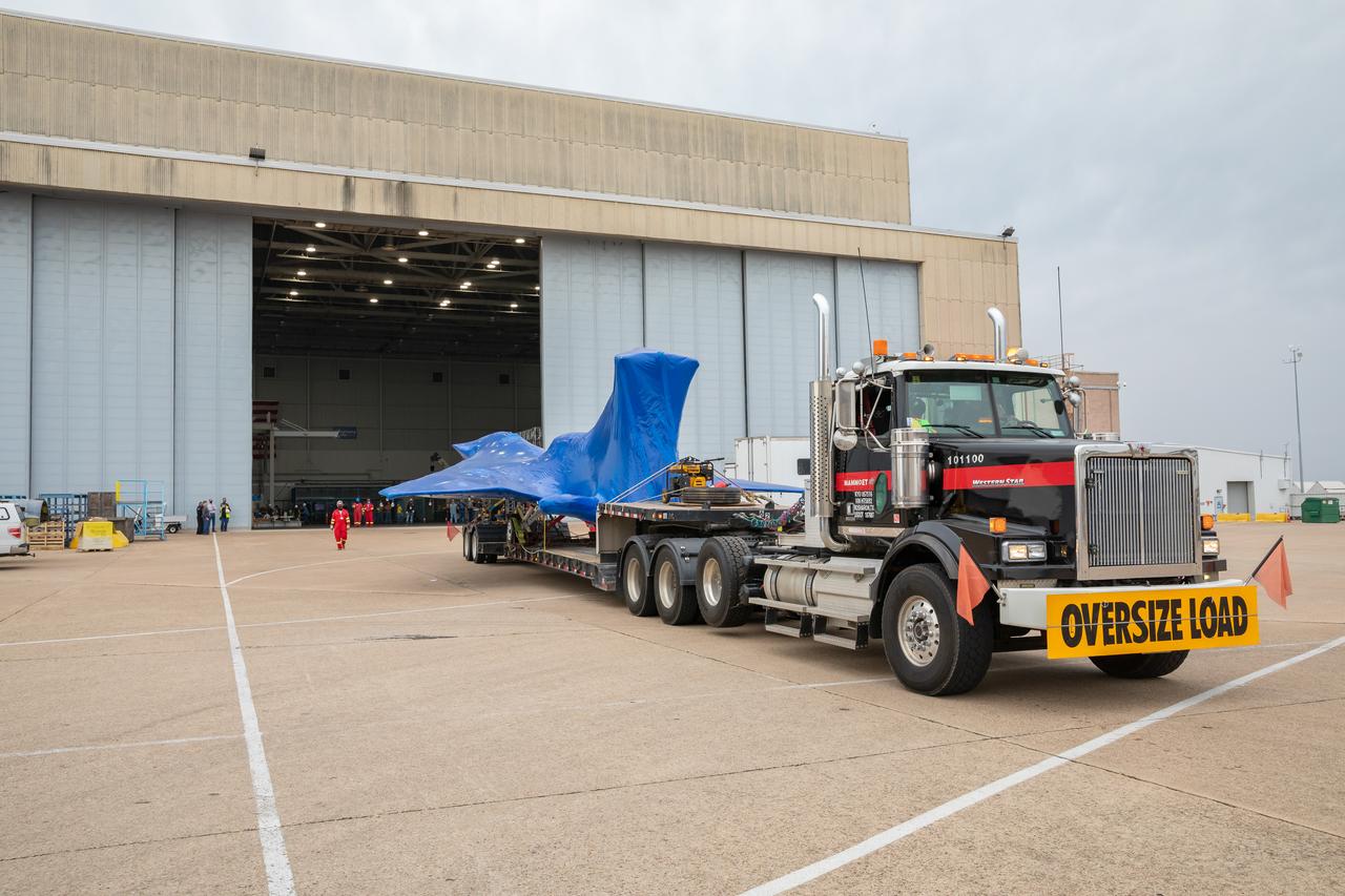
The X-59 arrives in Fort Worth, Texas from Palmdale, California, ready to undergo some important structural and fuel tests at the Lockheed Martin facility. The bright blue wrap around the X-plane is a precautionary measure to keep the exterior of the X-59 safe as it traveled through multiple states on its way to Texas.
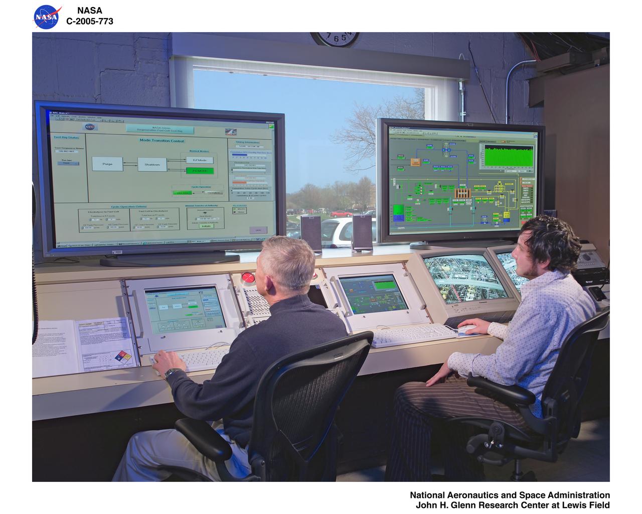
The closed loop regenerative fuel cell test. View inside the control room.
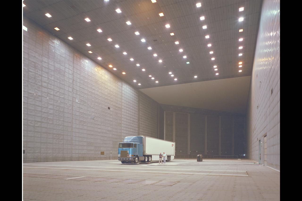
Fruehauf Truck and Trailer Test in 80x120ft W.T. (looking at drag and fuel efficiency)
Fuel Boiling Convection Experiment, FBCE Mission Sequence Test
Fuel Boiling Convection Experiment, FBCE Mission Sequence Test
Fuel Boiling Convection Experiment, FBCE Mission Sequence Test
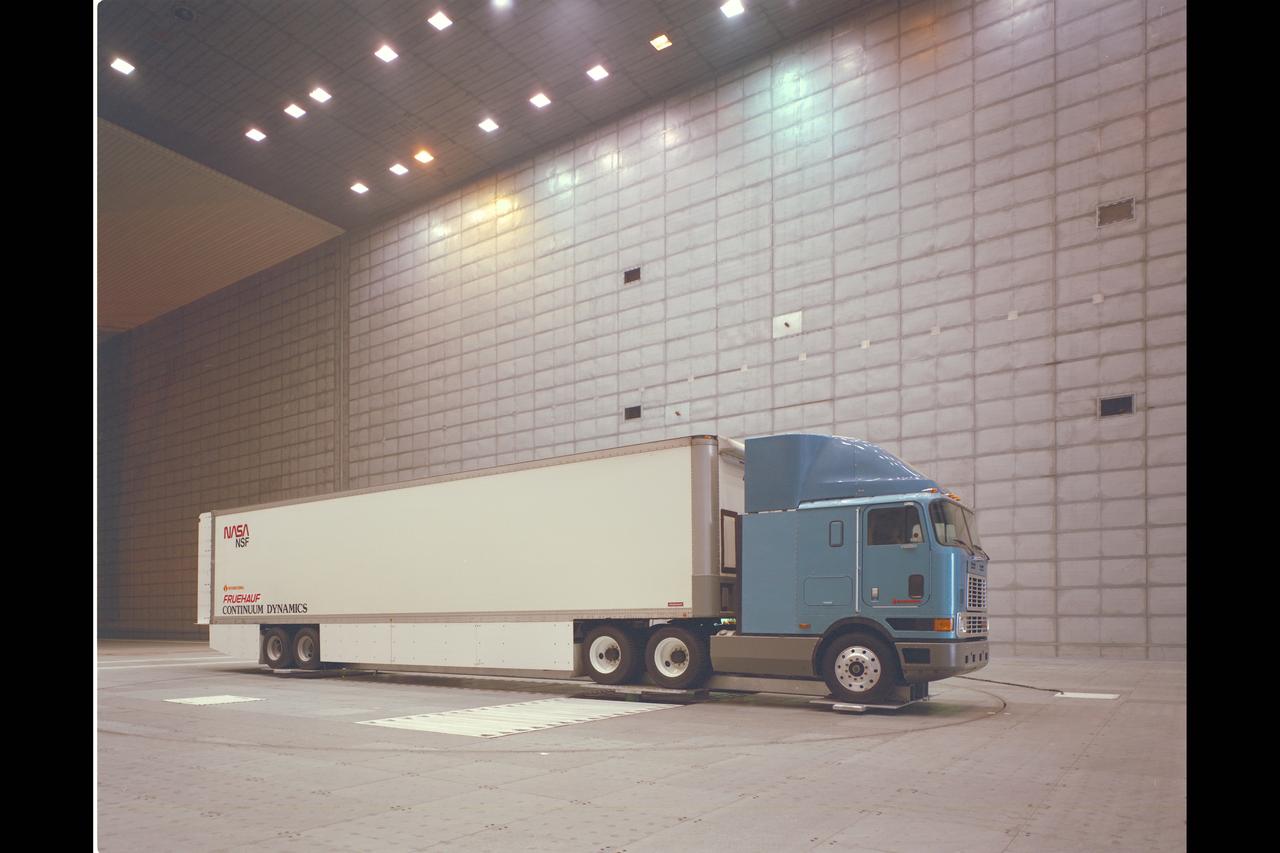
Fruehauf Truck and Trailer Test in 80x120ft W.T. (looking at drag and fuel efficiency)
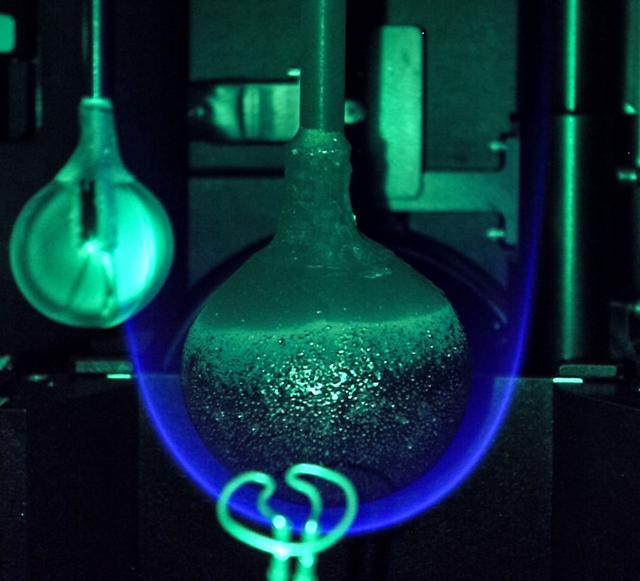
High Pressure Microgravity Combustion Experiment, HPMC, subjects liquid fuel droplets to high pressures and temperatures to study the ignition process in engine conditions, with a goal of improving fuel efficiency. In this configuration, the experiment is capable of testing droplet combustion at up to 100 atm of pressure, testing the droplet deployment system, which inserts the fuel droplet into the experiment.
High Pressure Microgravity Combustion Experiment, HPMC, subjects liquid fuel droplets to high pressures and temperatures to study the ignition process in engine conditions, with a goal of improving fuel efficiency. In this configuration, the experiment is capable of testing droplet combustion at up to 100 atm of pressure, testing the droplet deployment system, which inserts the fuel droplet into the experiment.
jsc2024e021222 (3/21/2024) --- Solid Fuel Ignition and Extinction (SoFIE) insert supports the Growth and Extinction Limit (GEL) investigation test image taken in the Combustion Integrated Rack (CIR). This image was taken just prior to flame extinction while the green LED was flashing on. The LED allows the fuel surface to be seen during the burn, so that several important parameters can be evaluated, such as how far the flame is from the fuel and how much the fuel is heating up. The igniter wire appears in the camera view, but it is in the foreground and not near the flame. In the background on the left, an unburned acrylic sphere waits for its turn to be tested on another day.
Fuels used in the 11 inch and 24 inch lab-scale hybrid motors are ignited at Marshall's test cell 104.
An eleven inch (11) hybrid motor gaseous oxygen (GOX) fuel firing at Marshall's test cell 103.
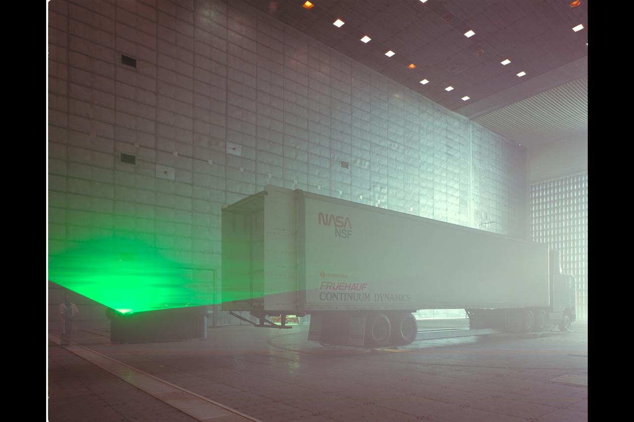
Fruehauf Truck and Trailer Test in 80x120ft W.T. with LRLDV (looking at drag and fuel efficiency)
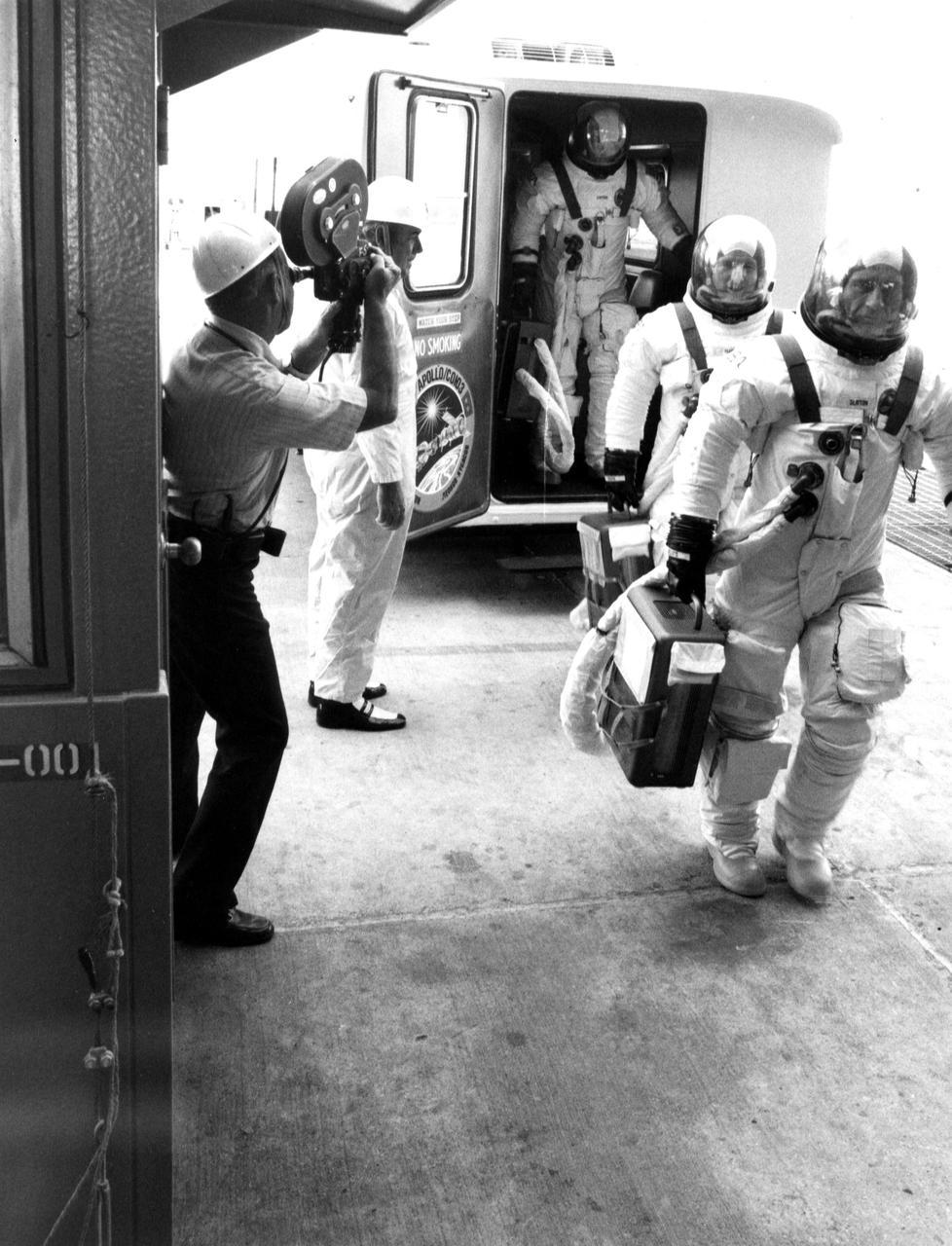
KENNEDY SPACE CENTER, FLA. -- ASTP asstronauts Donald slayton, Vance Brand and Thomas Stafford leave the transfer van at Complex 39's Pad B and enter the pad elevator during the Countdown Demonstration Test. The test, a step-by-step dress rehearsal for the July 15 launch, simulates the actual countdown but without the propellants in the Saturn IB launch vehicle's fuel tanks. The fueled portion of the test was conducted yesterday.
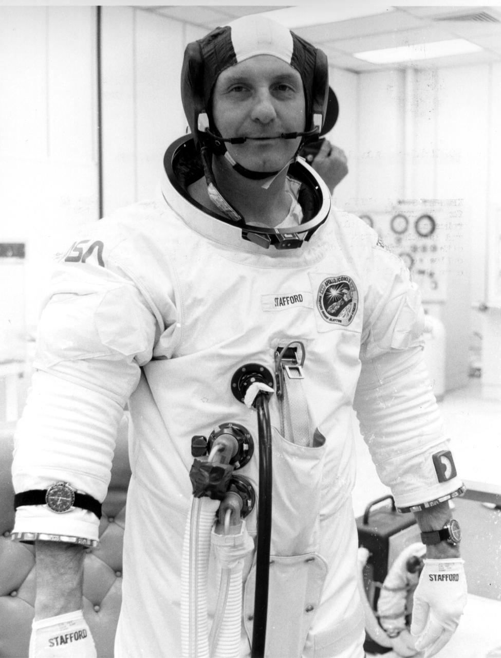
KENNEDY SPACE CENTER, FLA. -- ASTP crewman Thomas Stafford is suited up for the Countdown Demonstration Test. The test, a step-by-step dress rehearsal for the July 15 luanch, will culminate in a simulated T-zero and launch. Yesterday the 'wet' portion of the test was conducted with the vehicle fueled as it will be on launch day. The fuels were offloaded and the terminal portion of the count repeated with the prime crew aboard the spacecraft.
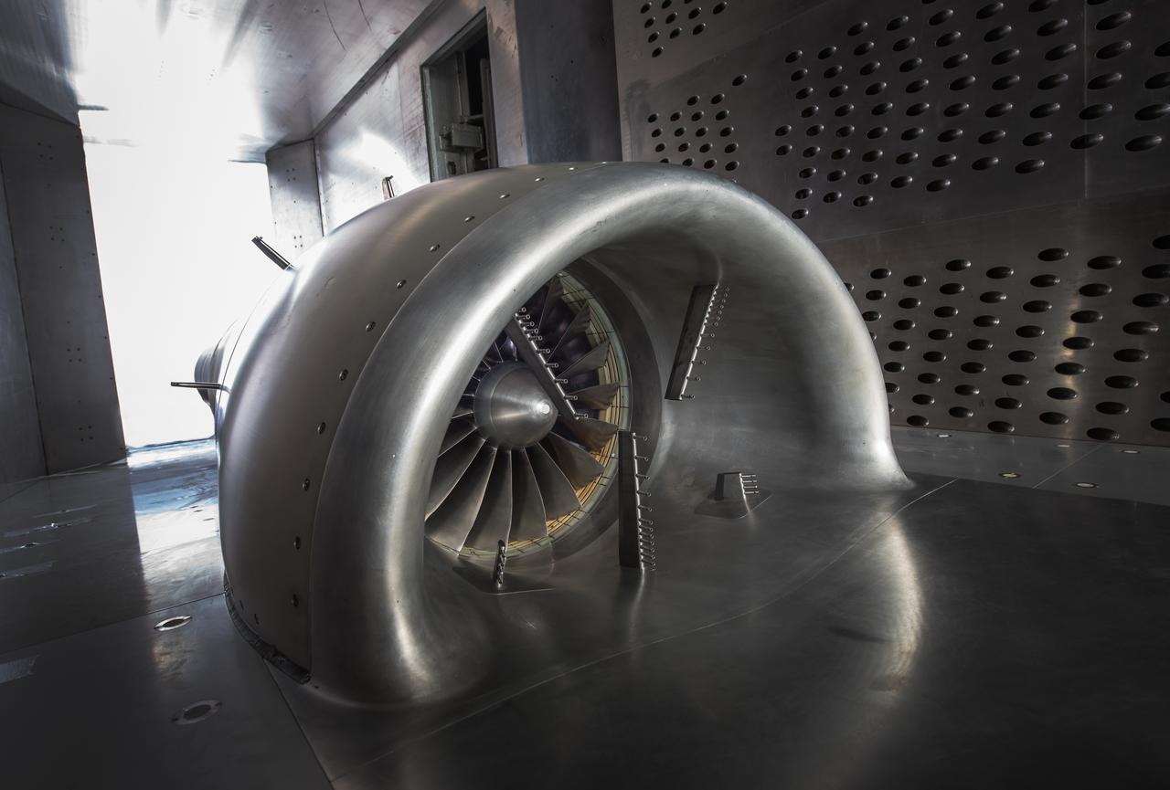
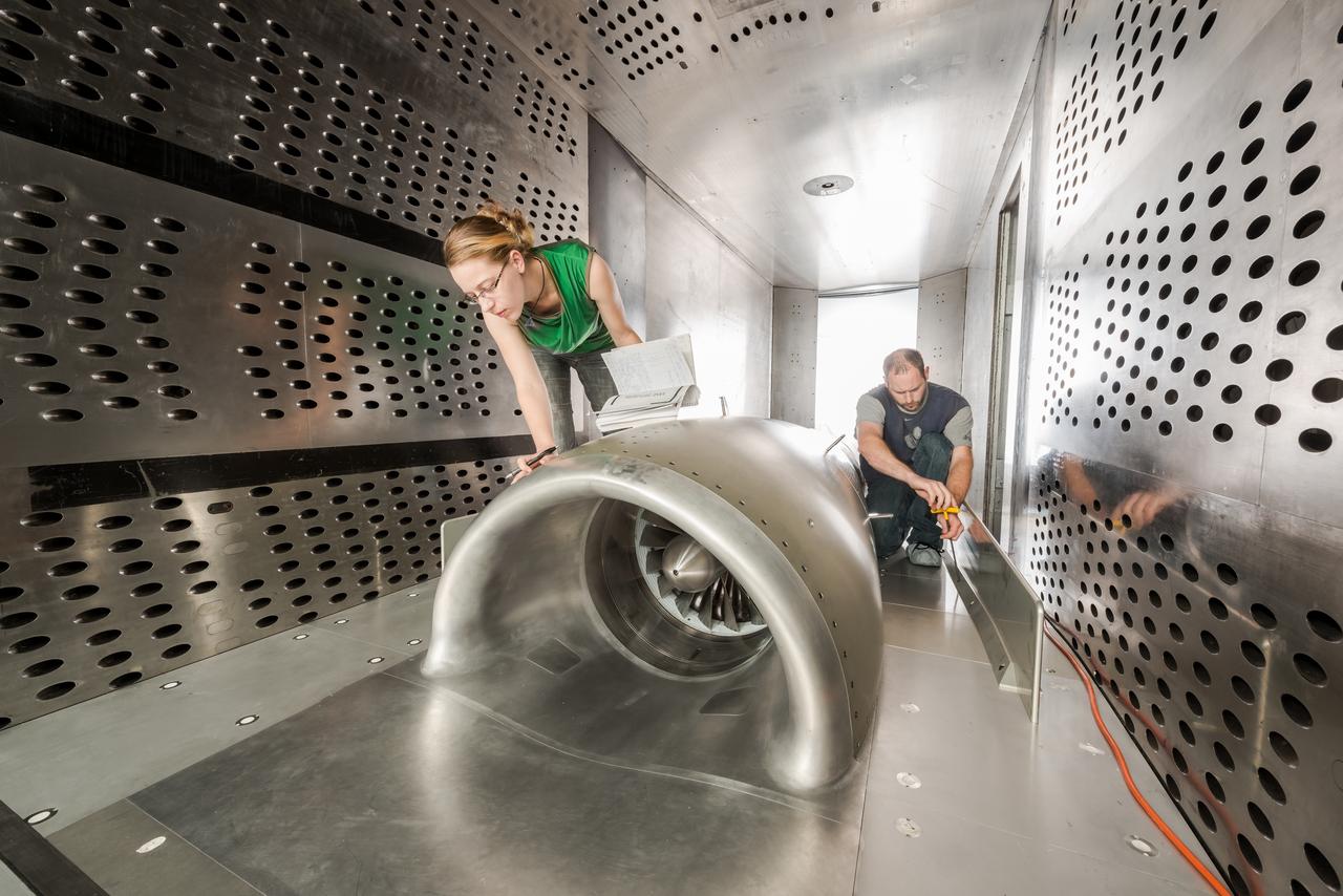
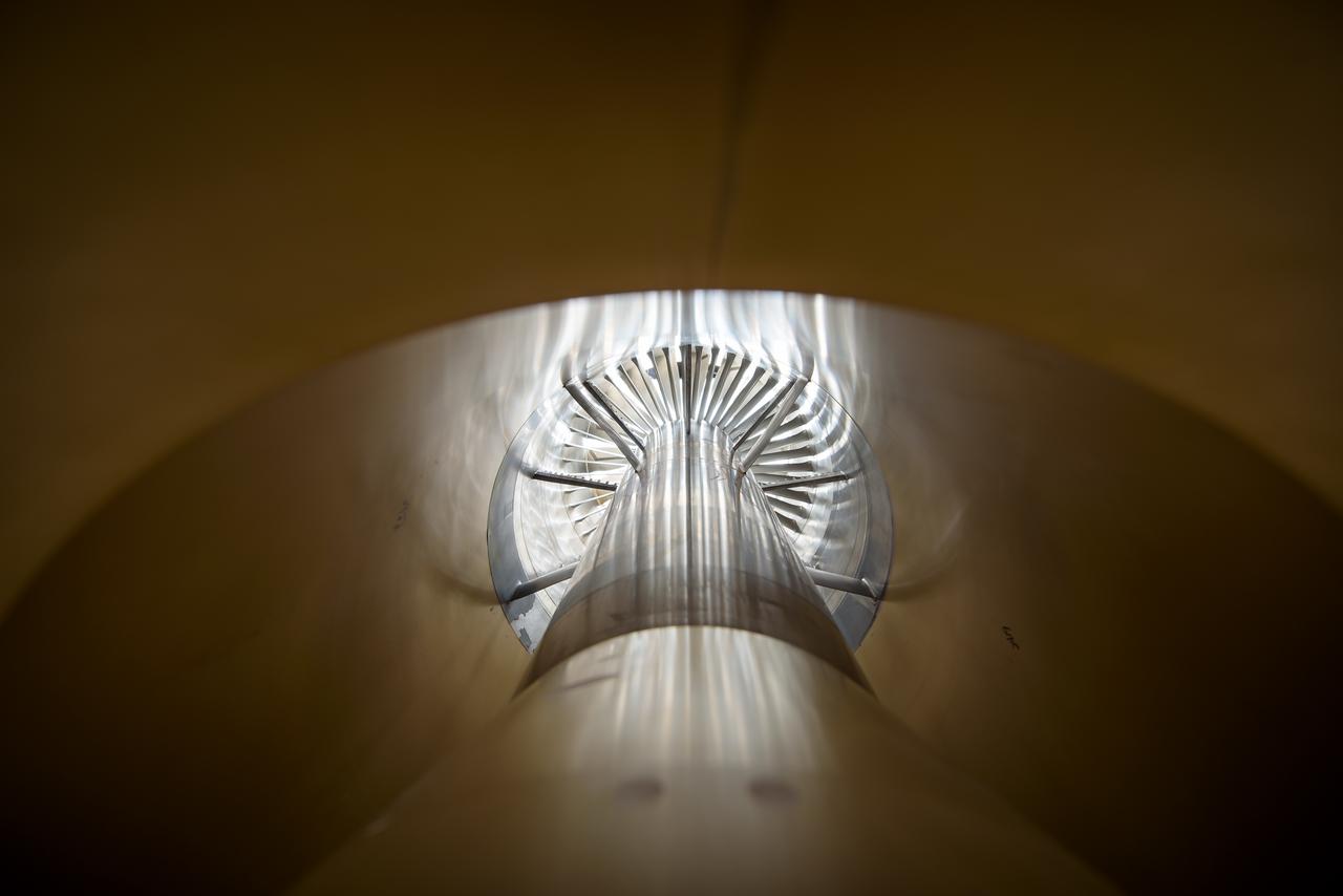
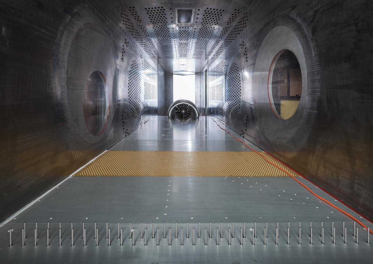
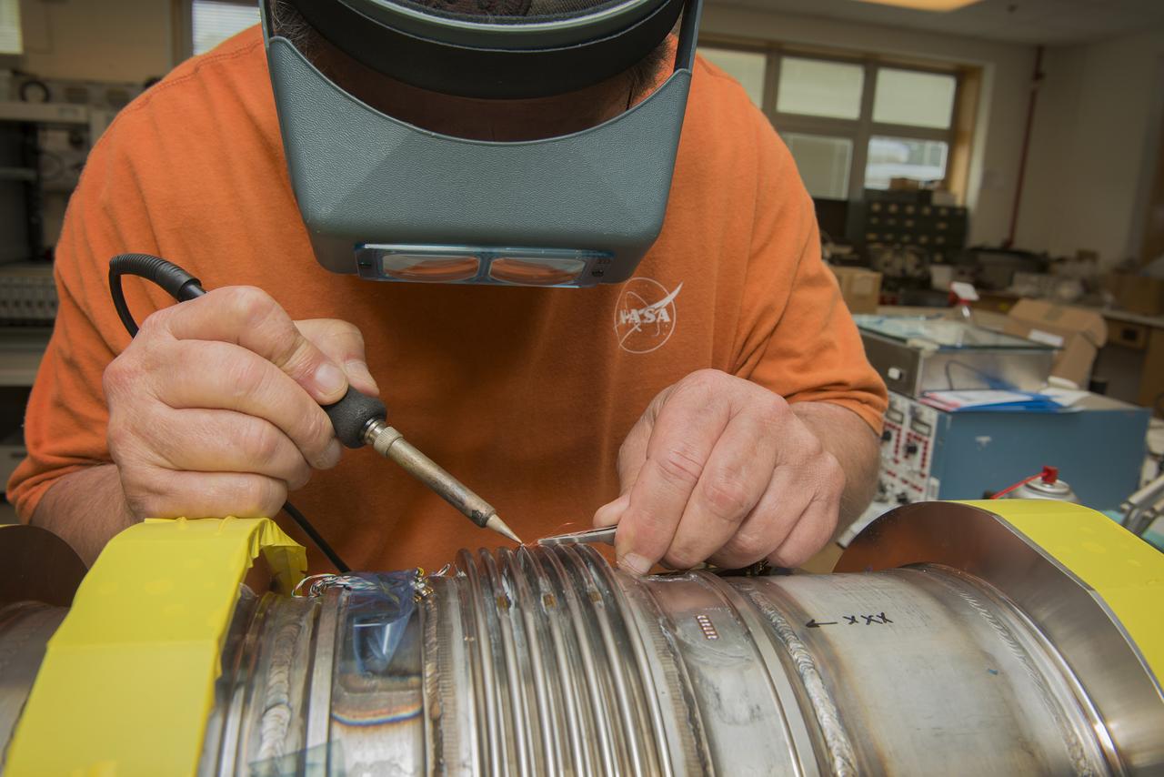
In an effort to improve fuel efficiency, NASA and the aircraft industry are rethinking aircraft design. Inside the 8' x 6' wind tunnel at NASA Glenn, engineers recently tested a fan and inlet design, commonly called a propulsor, which could use four to eight percent less fuel than today's advanced aircraft.
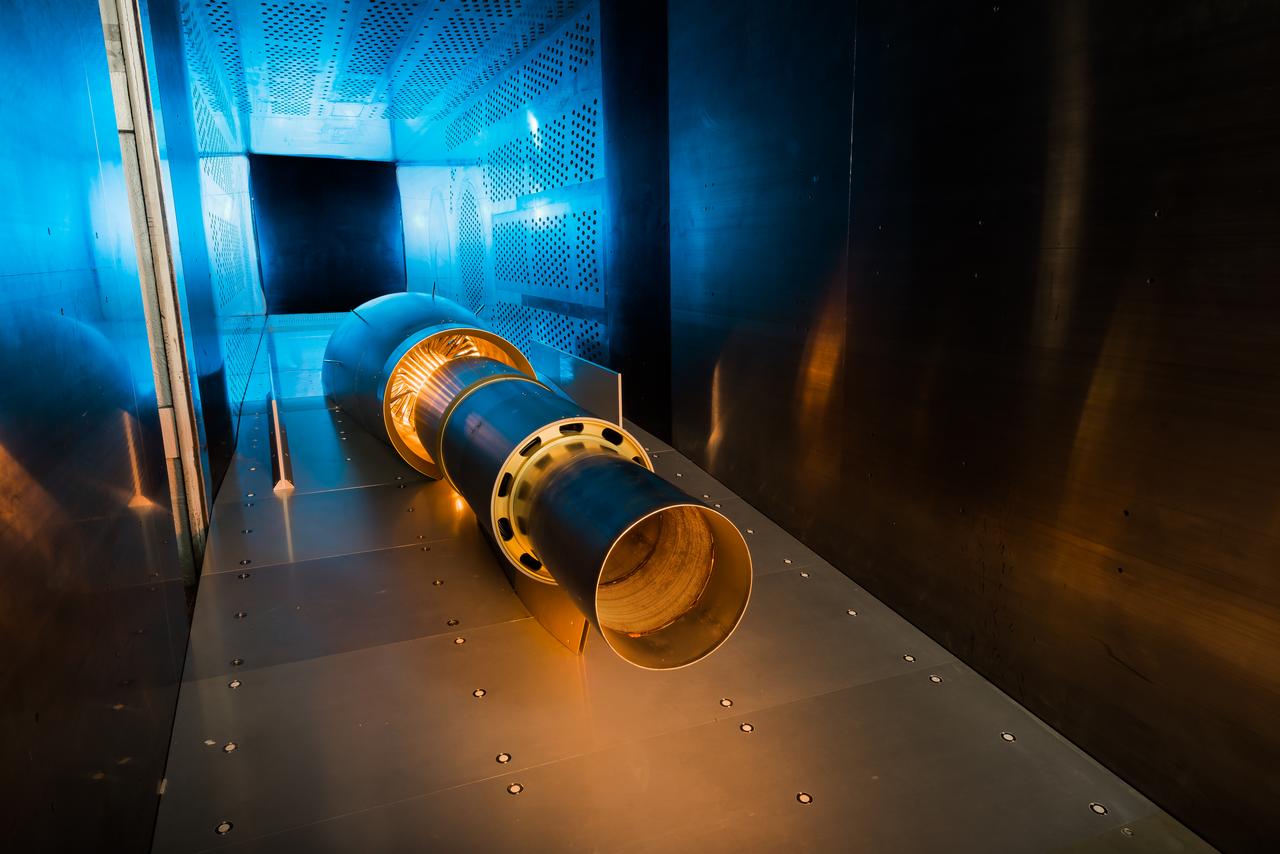
In an effort to improve fuel efficiency, NASA and the aircraft industry are rethinking aircraft design. Inside the 8' x 6' wind tunnel at NASA Glenn, engineers recently tested a fan and inlet design, commonly called a propulsor, which could use four to eight percent less fuel than today's advanced aircraft.
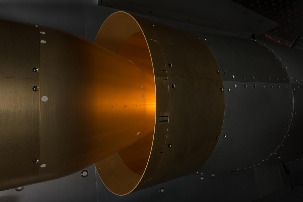
In an effort to improve fuel efficiency, NASA and the aircraft industry are rethinking aircraft design. Inside the 8' x 6' wind tunnel at NASA Glenn, engineers recently tested a fan and inlet design, commonly called a propulsor, which could use four to eight percent less fuel than today's advanced aircraft.
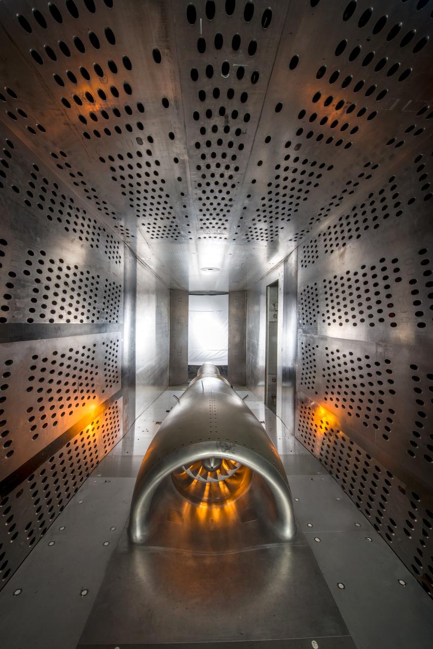
In an effort to improve fuel efficiency, NASA and the aircraft industry are rethinking aircraft design. Inside the 8' x 6' wind tunnel at NASA Glenn, engineers recently tested a fan and inlet design, commonly called a propulsor, which could use four to eight percent less fuel than today's advanced aircraft.
In an effort to improve fuel efficiency, NASA and the aircraft industry are rethinking aircraft design. Inside the 8' x 6' wind tunnel at NASA Glenn, engineers recently tested a fan and inlet design, commonly called a propulsor, which could use four to eight percent less fuel than today's advanced aircraft.
In an effort to improve fuel efficiency, NASA and the aircraft industry are rethinking aircraft design. Inside the 8' x 6' wind tunnel at NASA Glenn, engineers recently tested a fan and inlet design, commonly called a propulsor, which could use four to eight percent less fuel than today's advanced aircraft.
In an effort to improve fuel efficiency, NASA and the aircraft industry are rethinking aircraft design. Inside the 8' x 6' wind tunnel at NASA Glenn, engineers recently tested a fan and inlet design, commonly called a propulsor, which could use four to eight percent less fuel than today's advanced aircraft.

In an effort to improve fuel efficiency, NASA and the aircraft industry are rethinking aircraft design. Inside the 8' x 6' wind tunnel at NASA Glenn, engineers recently tested a fan and inlet design, commonly called a propulsor, which could use four to eight percent less fuel than today's advanced aircraft.

In an effort to improve fuel efficiency, NASA and the aircraft industry are rethinking aircraft design. Inside the 8' x 6' wind tunnel at NASA Glenn, engineers recently tested a fan and inlet design, commonly called a propulsor, which could use four to eight percent less fuel than today's advanced aircraft.
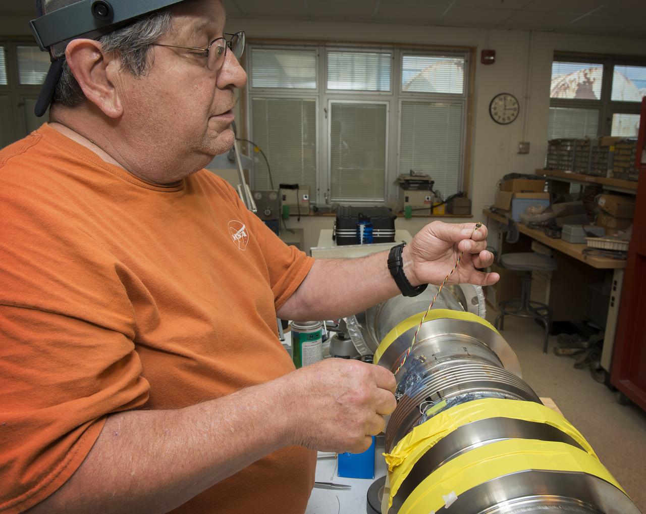
JOE MIRANDY, ET20, PREPARES SENSORS ON THE POGO Z- BAFFLE AND BELLOWS PRIOR TO FLOW TESTING. THE SENSORS WILL MEASURE VIBRATION AS FUEL FLOWS THROUGH THE TUBE AND BAFFLE.
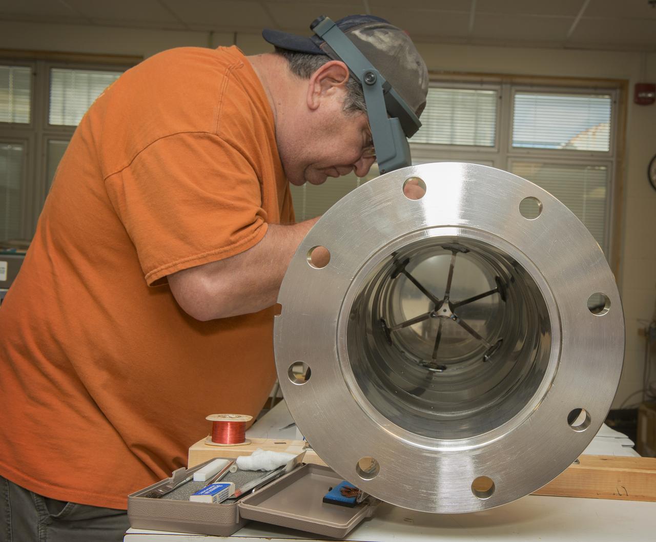
JOE MIRANDY, ET20, PREPARES SENSORS ON THE POGO Z- BAFFLE AND BELLOWS PRIOR TO FLOW TESTING. THE SENSORS WILL MEASURE VIBRATION AS FUEL FLOWS THROUGH THE TUBE AND BAFFLE.
JOE MIRANDY, ET20, PREPARES SENSORS ON THE POGO Z- BAFFLE AND BELLOWS PRIOR TO FLOW TESTING. THE SENSORS WILL MEASURE VIBRATION AS FUEL FLOWS THROUGH THE TUBE AND BAFFLE.
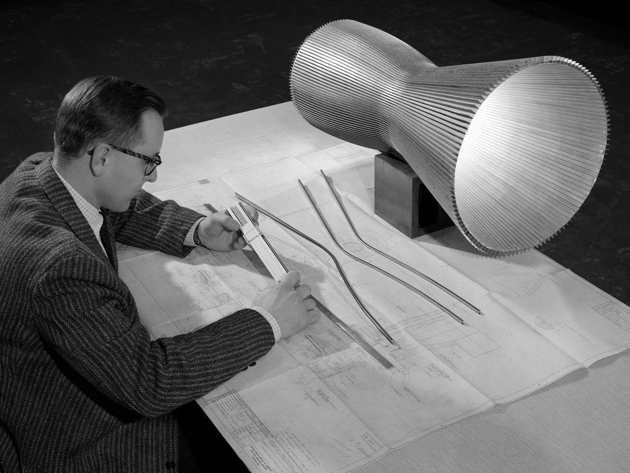
An engineer at the National Aeronautics and Space Administration (NASA) Lewis Research Center examines a drawing showing the assembly and details of a 20,000-pound thrust regeneratively cooled rocket engine. The engine was being designed for testing in Lewis’ new Rocket Engine Test Facility, which began operating in the fall of 1957. The facility was the largest high-energy test facility in the country that was capable of handling liquid hydrogen and other liquid chemical fuels. The facility’s use of subscale engines up to 20,000 pounds of thrust permitted a cost-effective method of testing engines under various conditions. The Rocket Engine Test Facility was critical to the development of the technology that led to the use of hydrogen as a rocket fuel and the development of lightweight, regeneratively-cooled, hydrogen-fueled rocket engines. Regeneratively-cooled engines use the cryogenic liquid hydrogen as both the propellant and the coolant to prevent the engine from burning up. The fuel was fed through rows of narrow tubes that surrounded the combustion chamber and nozzle before being ignited inside the combustion chamber. The tubes are visible in the liner sitting on the desk. At the time, Pratt and Whitney was designing a 20,000-pound thrust liquid-hydrogen rocket engine, the RL-10. Two RL-10s would be used to power the Centaur second-stage rocket in the 1960s. The successful development of the Centaur rocket and the upper stages of the Saturn V were largely credited to the work carried out Lewis.

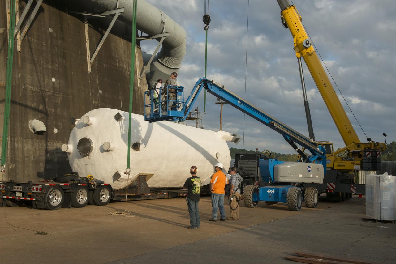
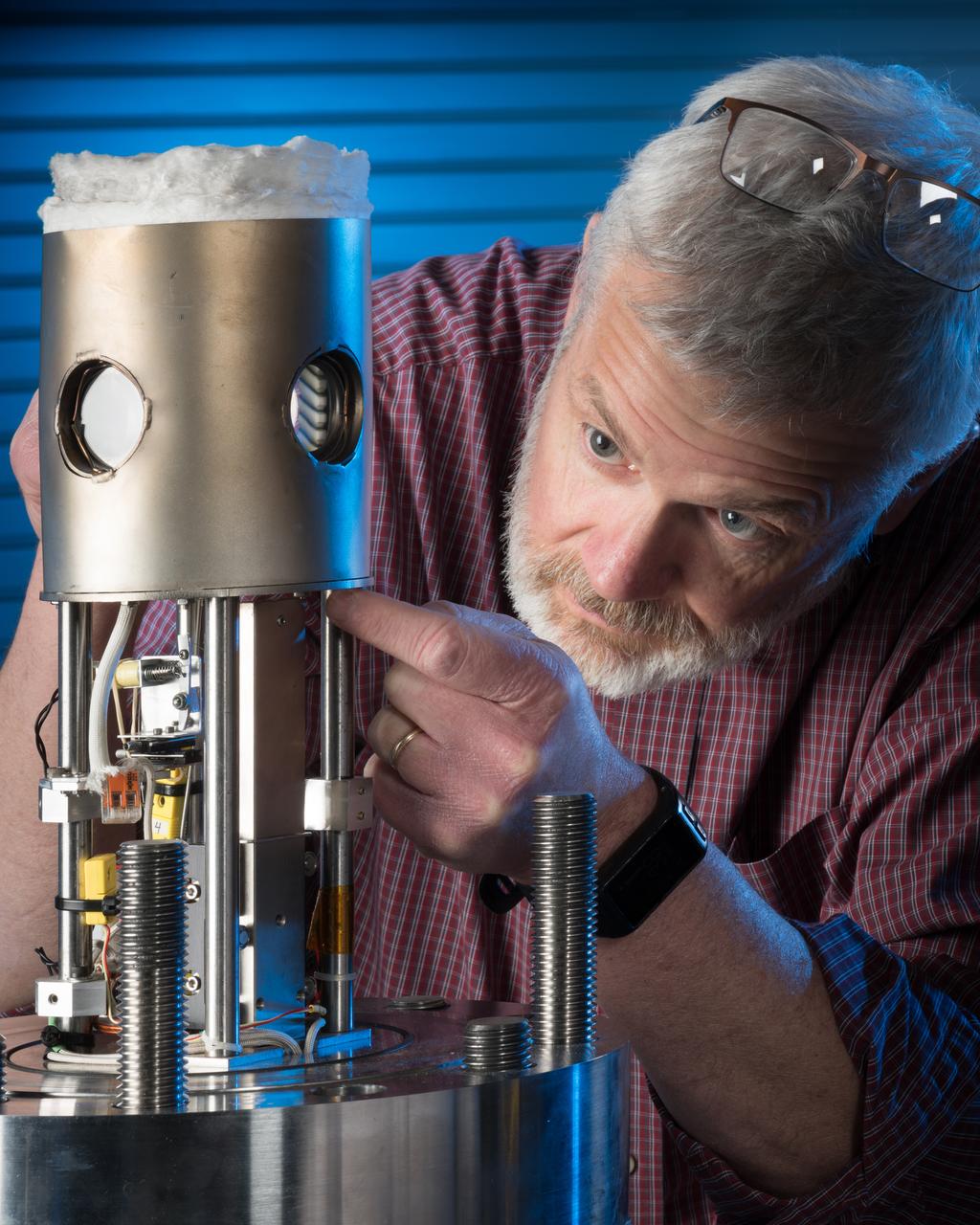
These photos show how teams at NASA’s Marshall Space Flight Center in Huntsville, Alabama, are testing an innovative approach to achieve zero boiloff storage of liquid hydrogen using two stages of active cooling, which could prevent the loss of valuable propellant during future long-duration spaceflight missions. Test teams installed the propellant tank in Test Stand 300 at NASA Marshall in early June, and the 90-day test campaign is scheduled to conclude in September. The tank is wrapped in a multi-layer insulation blanket that includes a thin aluminum heat shield fitted between layers. A second set of tubes, carrying helium at about minus 298 Fahrenheit, is integrated into the shield. This intermediate cooling layer intercepts and rejects incoming heat before it reaching the tank, easing the heat load on the tube-on-tank system. The Cryogenic Fluid Management Portfolio Project is a cross-agency team based at NASA Marshall and the agency’s Glenn Research Center in Cleveland. The cryogenic portfolio’s work is under NASA’s Technology Demonstration Missions Program, part of NASA’s Space Technology Mission Directorate, and is comprised of more than 20 individual technology development activities. For more information, contact NASA Marshall’s Office of Communications at 256-544-0034.
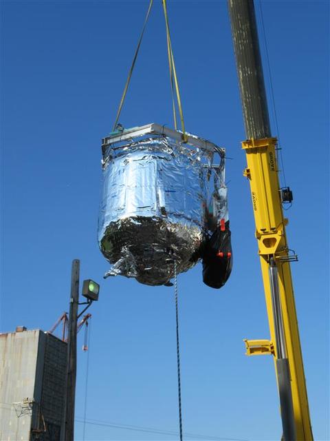
These photos show how teams at NASA’s Marshall Space Flight Center in Huntsville, Alabama, are testing an innovative approach to achieve zero boiloff storage of liquid hydrogen using two stages of active cooling, which could prevent the loss of valuable propellant during future long-duration spaceflight missions. Test teams installed the propellant tank in Test Stand 300 at NASA Marshall in early June, and the 90-day test campaign is scheduled to conclude in September. The tank is wrapped in a multi-layer insulation blanket that includes a thin aluminum heat shield fitted between layers. A second set of tubes, carrying helium at about minus 298 Fahrenheit, is integrated into the shield. This intermediate cooling layer intercepts and rejects incoming heat before it reaching the tank, easing the heat load on the tube-on-tank system. The Cryogenic Fluid Management Portfolio Project is a cross-agency team based at NASA Marshall and the agency’s Glenn Research Center in Cleveland. The cryogenic portfolio’s work is under NASA’s Technology Demonstration Missions Program, part of NASA’s Space Technology Mission Directorate, and is comprised of more than 20 individual technology development activities. For more information, contact NASA Marshall’s Office of Communications at 256-544-0034.
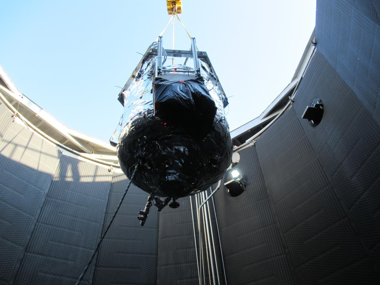
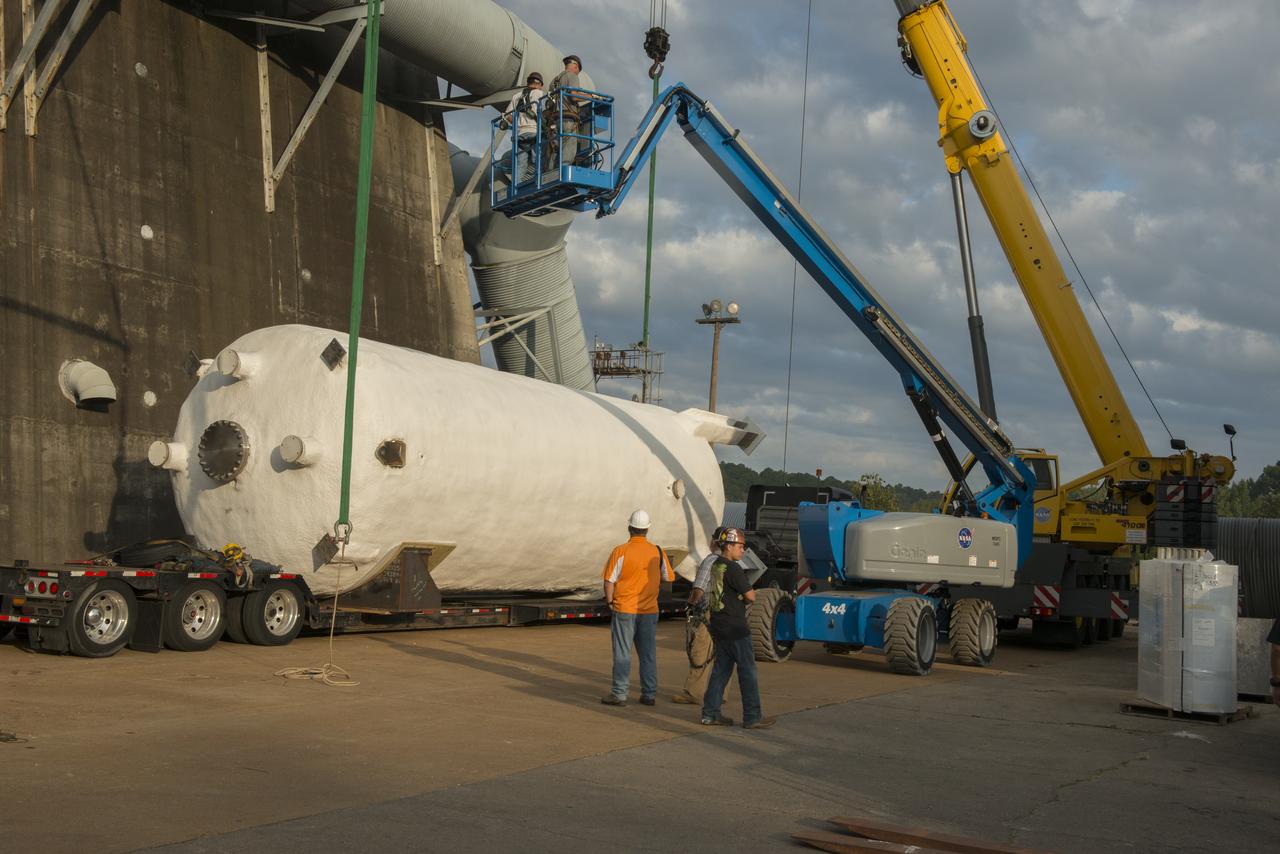
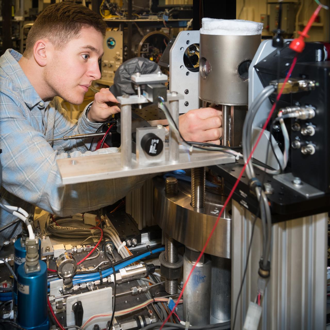
These photos show how teams at NASA’s Marshall Space Flight Center in Huntsville, Alabama, are testing an innovative approach to achieve zero boiloff storage of liquid hydrogen using two stages of active cooling, which could prevent the loss of valuable propellant during future long-duration spaceflight missions. Test teams installed the propellant tank in Test Stand 300 at NASA Marshall in early June, and the 90-day test campaign is scheduled to conclude in September. The tank is wrapped in a multi-layer insulation blanket that includes a thin aluminum heat shield fitted between layers. A second set of tubes, carrying helium at about minus 298 Fahrenheit, is integrated into the shield. This intermediate cooling layer intercepts and rejects incoming heat before it reaching the tank, easing the heat load on the tube-on-tank system. The Cryogenic Fluid Management Portfolio Project is a cross-agency team based at NASA Marshall and the agency’s Glenn Research Center in Cleveland. The cryogenic portfolio’s work is under NASA’s Technology Demonstration Missions Program, part of NASA’s Space Technology Mission Directorate, and is comprised of more than 20 individual technology development activities. For more information, contact NASA Marshall’s Office of Communications at 256-544-0034.
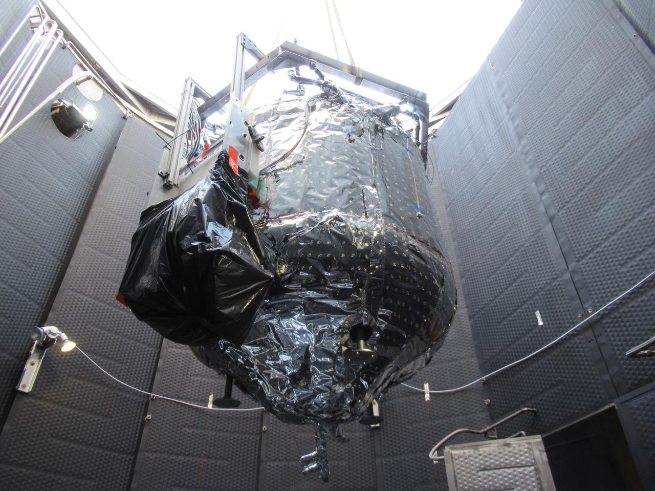
These photos show how teams at NASA’s Marshall Space Flight Center in Huntsville, Alabama, are testing an innovative approach to achieve zero boiloff storage of liquid hydrogen using two stages of active cooling, which could prevent the loss of valuable propellant during future long-duration spaceflight missions. Test teams installed the propellant tank in Test Stand 300 at NASA Marshall in early June, and the 90-day test campaign is scheduled to conclude in September. The tank is wrapped in a multi-layer insulation blanket that includes a thin aluminum heat shield fitted between layers. A second set of tubes, carrying helium at about minus 298 Fahrenheit, is integrated into the shield. This intermediate cooling layer intercepts and rejects incoming heat before it reaching the tank, easing the heat load on the tube-on-tank system. The Cryogenic Fluid Management Portfolio Project is a cross-agency team based at NASA Marshall and the agency’s Glenn Research Center in Cleveland. The cryogenic portfolio’s work is under NASA’s Technology Demonstration Missions Program, part of NASA’s Space Technology Mission Directorate, and is comprised of more than 20 individual technology development activities. For more information, contact NASA Marshall’s Office of Communications at 256-544-0034.
COLD FLOW - Liquid oxygen runs through the piping on Stennis Space Center's A-1 Test Stand on Dec. 18 to test the ability of the J-2X engine's Powerpack 1A to withstand the temperature change and pressure. Just visible above and to the right of the test article's nozzle is a frosty pipe, indicating the supercold fuel is flowing as it should.
At the Marshall Space Flight Center (MSFC), the fuel tank assembly for the Saturn V S-IC-T (static test stage) fuel tank assembly is mated to the liquid oxygen (LOX) tank in building 4705. This stage underwent numerous static firings at the newly-built S-IC Static Test Stand at the MSFC west test area. The S-IC (first) stage used five F-1 engines that produced a total thrust of 7,500,000 pounds as each engine produced 1,500,000 pounds of thrust. The S-IC stage lifted the Saturn V vehicle and Apollo spacecraft from the launch pad.

KENNEDY SPACE CENTER, FLA. - Patricia Slinger (left), a test engineer, and Monica Hagley, an avionics test engineer, look at a replacement orbiter point sensor chassis. Components are being tested to determine why one of the four liquid hydrogen tank low-level fuel cut-off sensors failed in a routine prelaunch check during the launch countdown July 13. The failure caused mission managers to scrub Discovery's first launch attempt. The sensor protects the Shuttle's main engines by triggering their shutdown in the event fuel runs unexpectedly low. The sensor is one of four inside the liquid hydrogen section of the External Tank (ET).

Technicians complete foaming around the area of Atlantis, Orbiter Vehicle (OV) 104, 17 inch diameter external tank (ET) feed line in preparation for the second liquid hydrogen tanking test at the Kennedy Space Center (KSC). An elaborate network of sensors, leak detectors, and baggies were set up on OV-104 by technicians. Engineers hope this extra instrumentation will help pinpoint the exact location of the leak. OV-104 is scheduled to be launched for the STS-38 mission, a classified Department of Defense (DOD) flight. View provided by KSC with alternate number KSC-90PC-988.
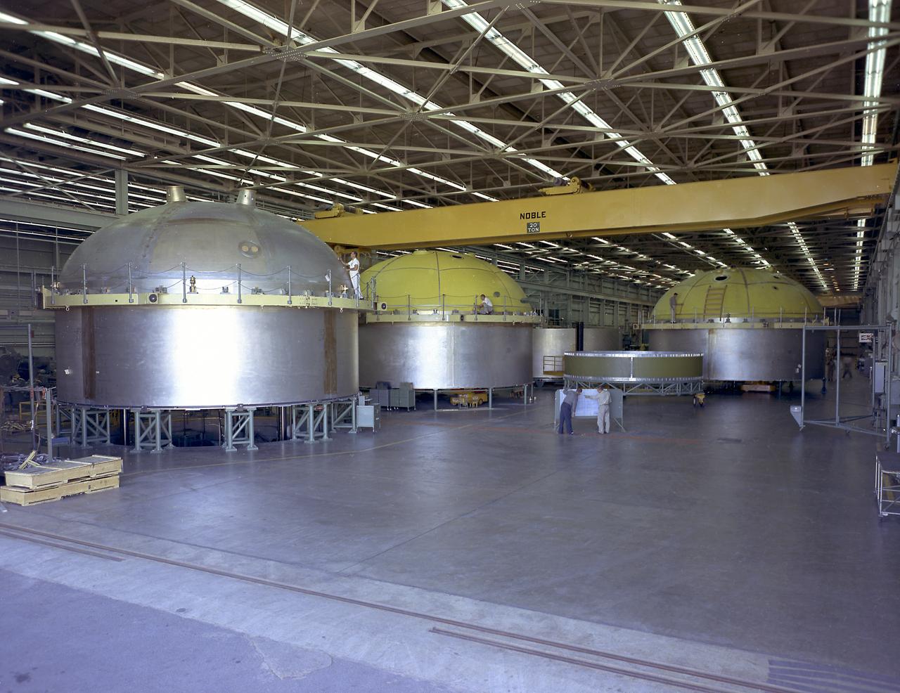
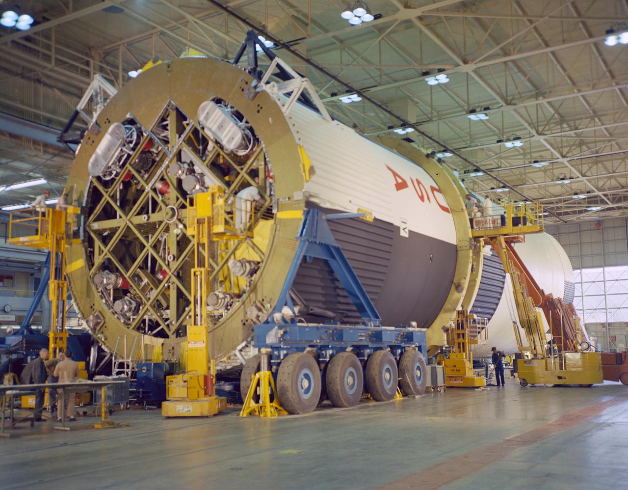
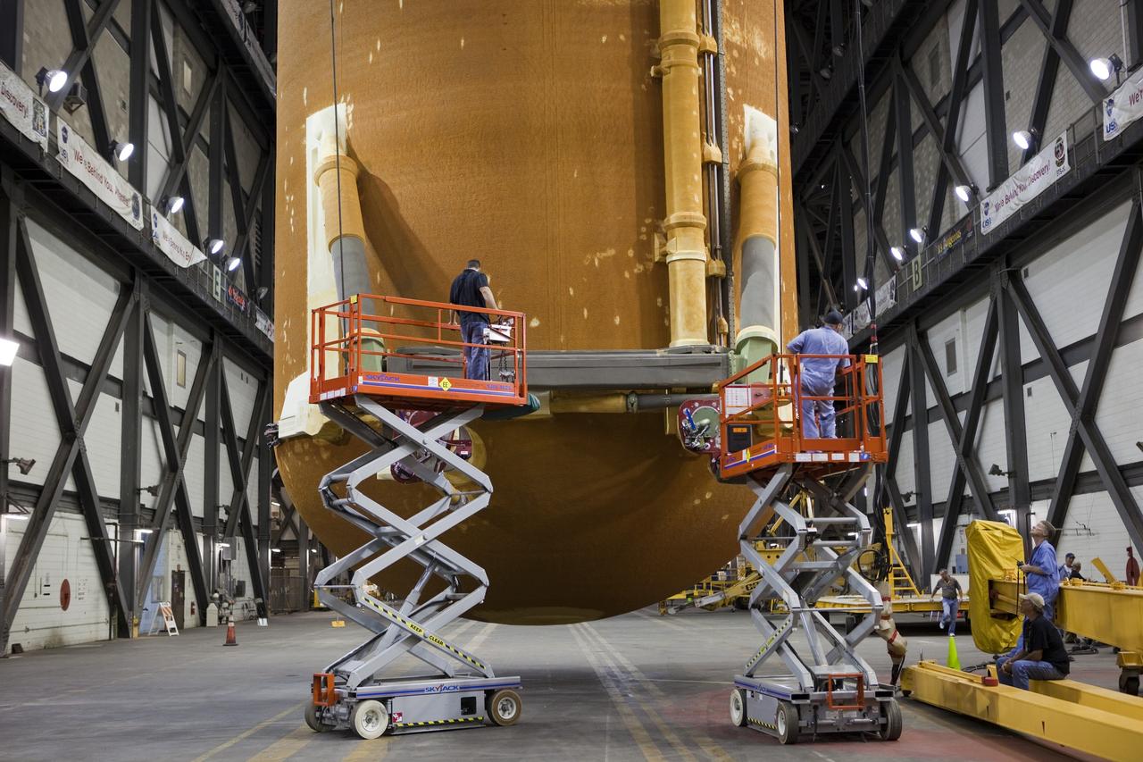
The components of the Saturn V booster (S-IC stage) fuel tank are shown in this photograph. The liquid oxygen tank bulkhead on the left and both halves of the fuel tank were in the Marshall Space Flight Center (MSFC) Manufacturing Engineering Laboratory, building 4707. These components were used at MSFC in structural testing to prove that they could withstand the forces to which they were subjected in flight. Each S-IC stage has two tanks, one for kerosene and one for liquid oxygen, made from such components as these. Thirty-three feet in diameter, they hold a total of 4,400,000 pounds of fuel. Although this tankage was assembled at MSFC, the elements were made by the Boeing Company at Wichita and the Michoud Operations at New Orleans.
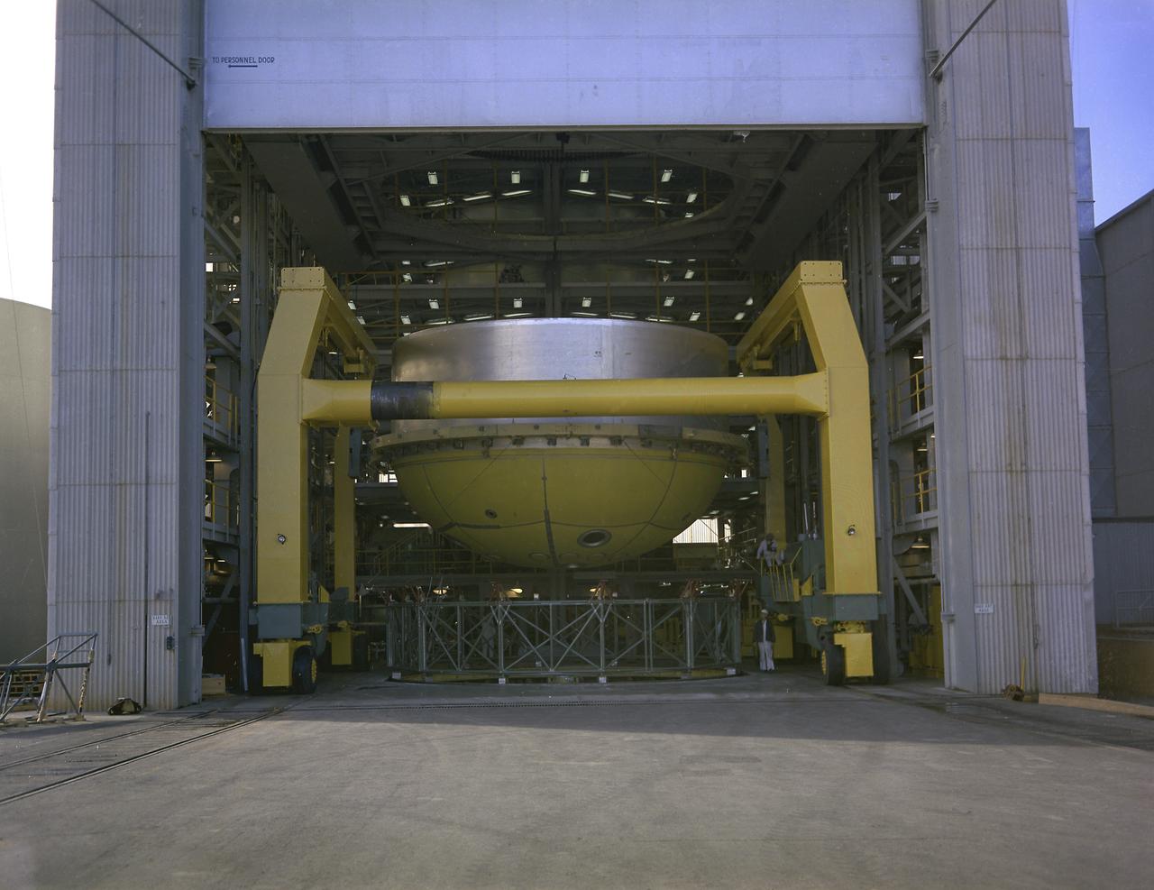
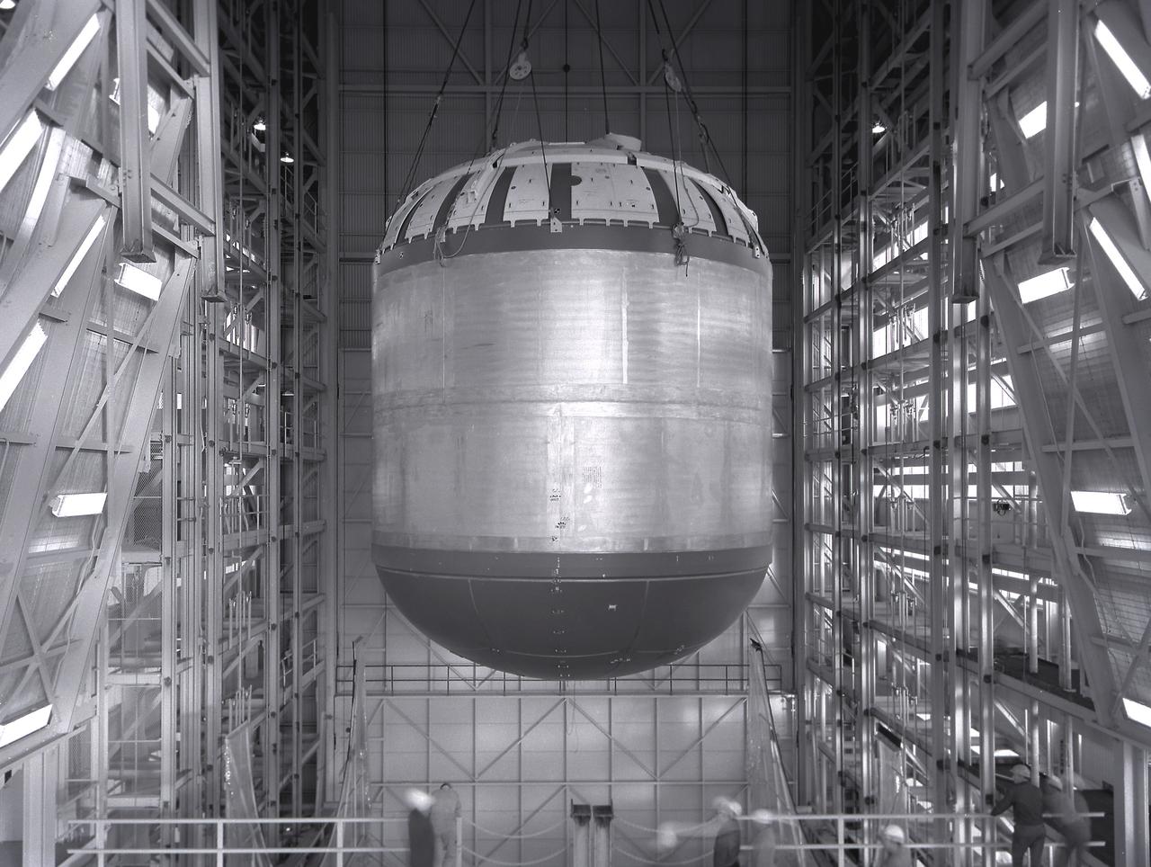
This photograph shows a fuel tank lower half for the Saturn V S-IC-T stage (the S-IC stage for static testing) on a C-frame transporter inside the vertical assembly building at the Marshall Space Flight Center.
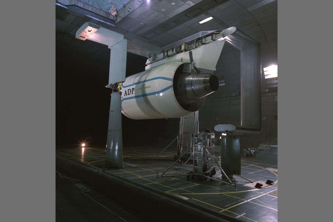
Pratt & Whitney Advanced Ducted Propulsor (ADP) Engine Test-590 in the NASA Ames 40x80ft Subsonic Wind Tunnel. The Pratt & Whitney Advanced Ducted Prop (ADP) demonstrator undergoing acoustic and fan performance testing. ADP technology could lead to decreased fuel consumption and noise.
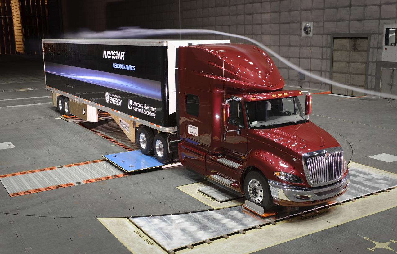
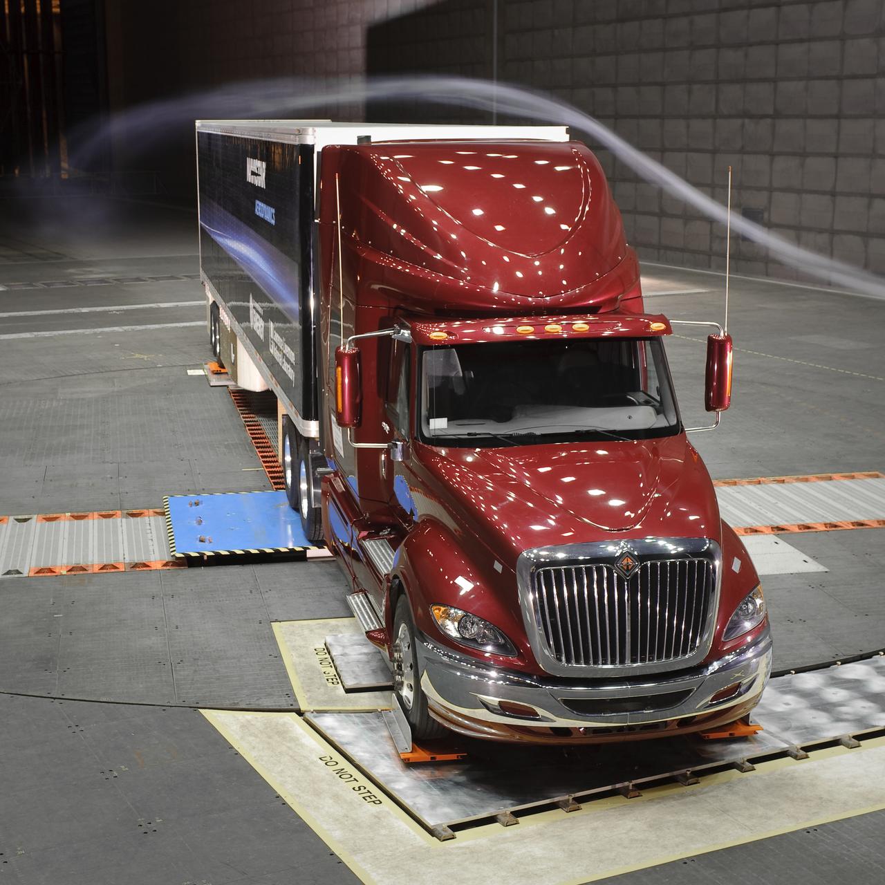
Lawrence Livermore National Labs (LLNL), Navistar and the Department of Energy conduct tests in the NASA Ames National Full-scale Aerodynamic Complex 80x120_foot wind tunnel. The LLNL project is aimed at aerodynamic truck and trailer devices that can reduce fuel consumption at highway speed by 10 percent. Smoke test demo.
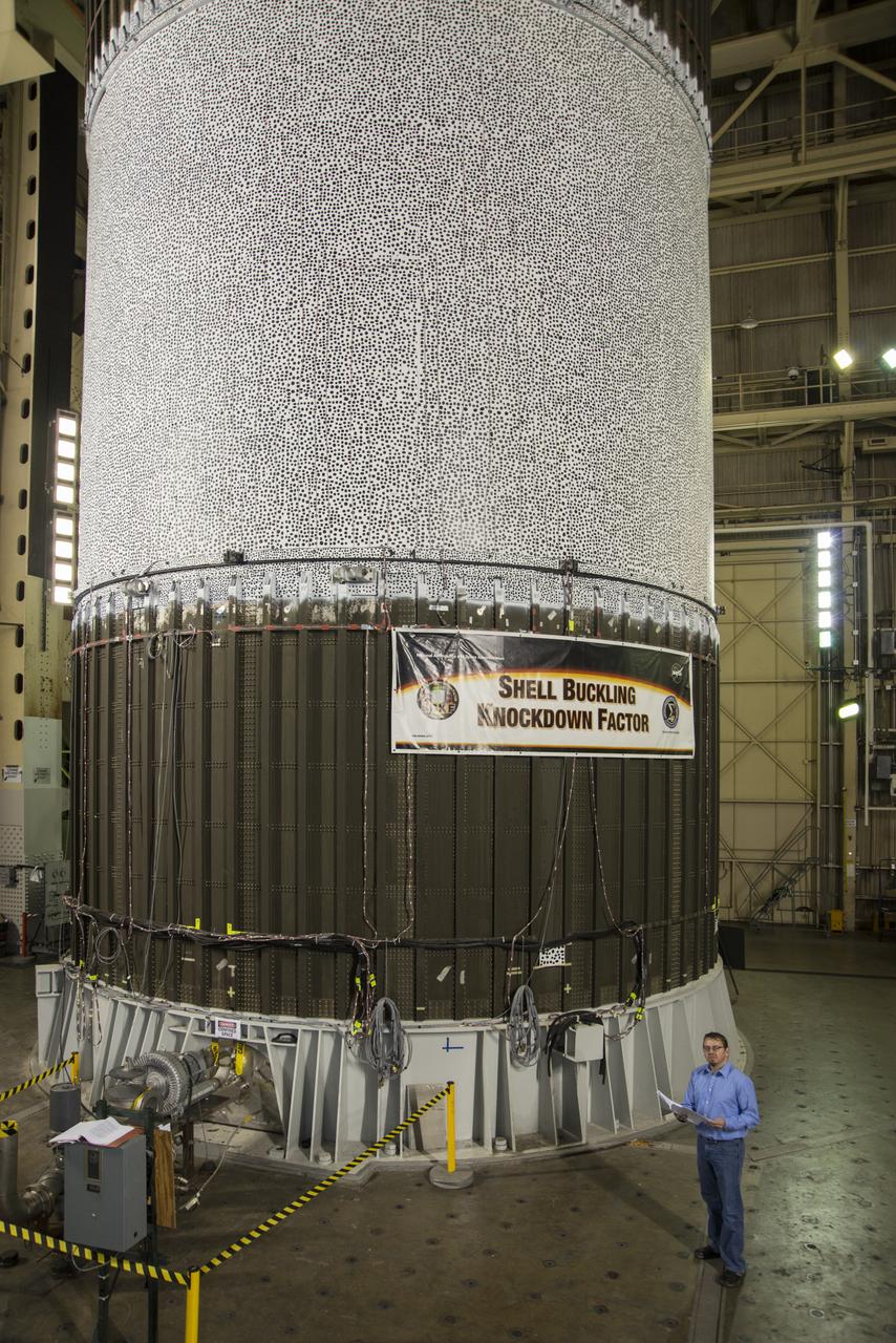
MARK HILBURGER, PROJECT ENGINEER FROM LANGLEY RESEARCH CENTER (LARC) WITH THE ALUMINUM-LITHIUM CYLINDER USED IN THE SHELL BUCKLE KNOCKDOWN FACTOR TESTING. DURING THE TESTING FORCE AND PRESSURE WERE INCREASINGLY APPLIED TO THE TOP OF AN EMPTY BUT PRESSURIZED ROCKET FUEL TANK TO EVALUATE ITS STRUCTURAL INTEGRITY.
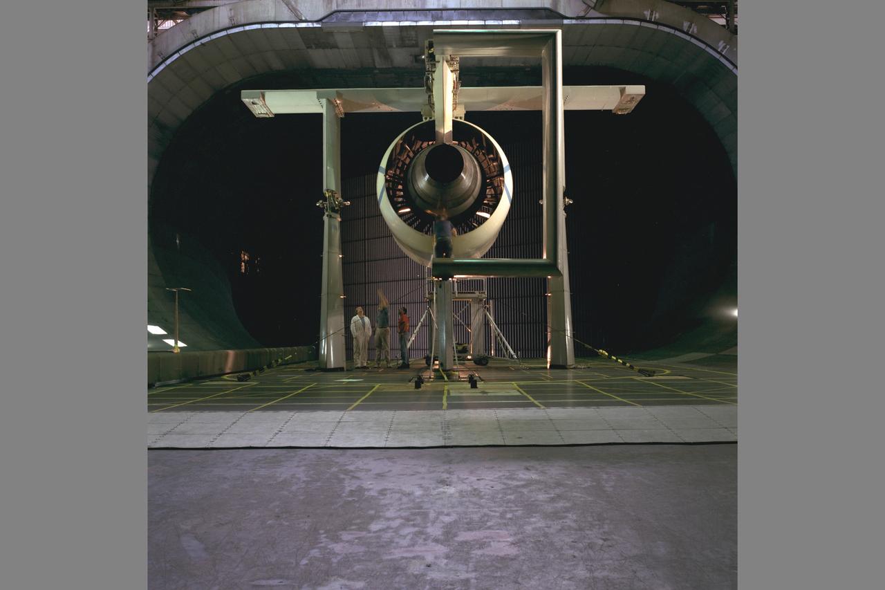
Pratt & Whitney Advanced Ducted Propulsor (ADP) Engine Test-590 in NASA Ames 40x80ft Subsonic Wind Tunnel. The Pratt & Whitney advanced ducted prop (ADP) demonstrator undergoing acoustic and fan performance testing. ADP technology could lead to decreased fuel consumption and noise.
Lawrence Livermore National Labs (LLNL), Navistar and the Department of Energy conduct tests in the NASA Ames National Full-scale Aerodynamic Complex 80x120_foot wind tunnel. The LLNL project is aimed at aerodynamic truck and trailer devices that can reduce fuel consumption at highway speed by 10 percent. Smoke test demo.
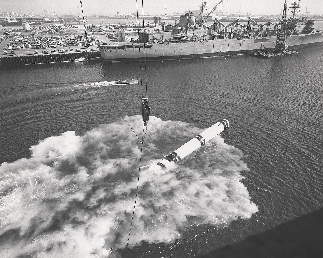
As early as September 1972, the Marshall Space Flight Center arnounced plans for a series of 20 water-entry simulation tests with a solid-fueled rocket casing assembly. The tests would provide valuable data for assessment of solid rocket booster parachute water recovery and aid in preliminary solid rocket motor design.
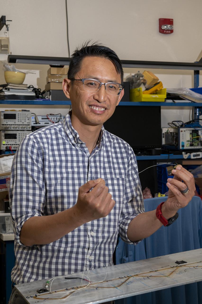
NASA’s Armstrong Flight Research Center’s FOSS, Fiber Optic Sensing System, recently supported tests of a system designed to turn oxygen into liquid oxygen, a component of rocket fuel. Patrick Chan, electronics engineer, and NASA Armstrong’s FOSS portfolio project manager, shows fiber like that used in the testing.
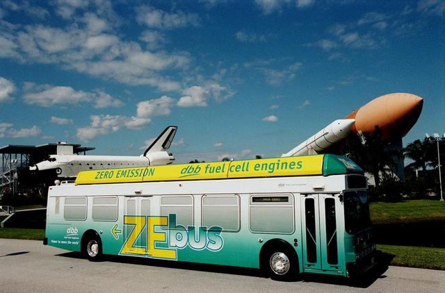
The Zero Emissions (ZE) transit bus tours the KSC Visitor Complex for a test ride. In the background are a mock-up orbiter named Explorer (left) and a stack of solid rocket boosters and external tank (right), typically used on Shuttle launches. Provided by dbb fuel cell engines inc. of Vancouver, Canada, the ZE bus was brought to KSC as part of the Center's Alternative Fuel Initiatives Program. The bus uses a Proton Exchange Membrane fuel cell in which hydrogen and oxygen, from atmospheric air, react to produce electricity that powers an electric motor drive system. The by-product "exhaust" from the fuel cell is water vapor, thus zero harmful emissions. A typical diesel-powered bus emits more than a ton of harmful pollutants from its exhaust every year. The ZE bus is being used on tour routes at the KSC Visitor Complex for two days to introduce the public to the concept

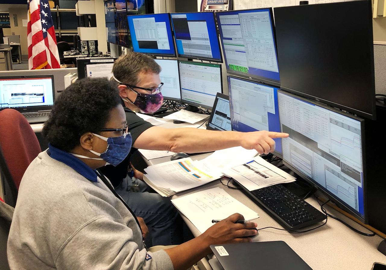
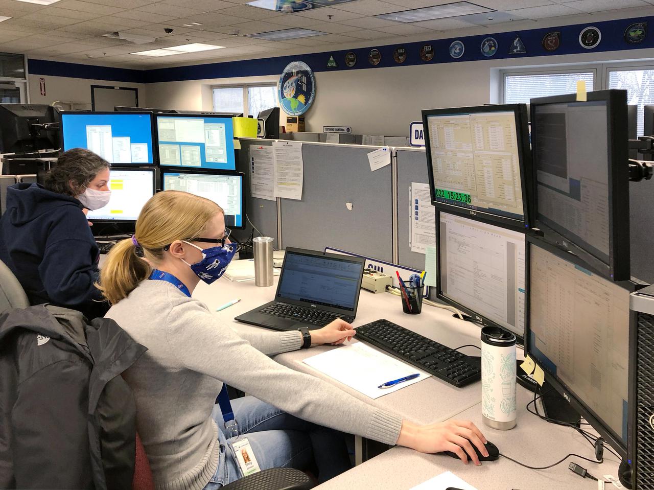
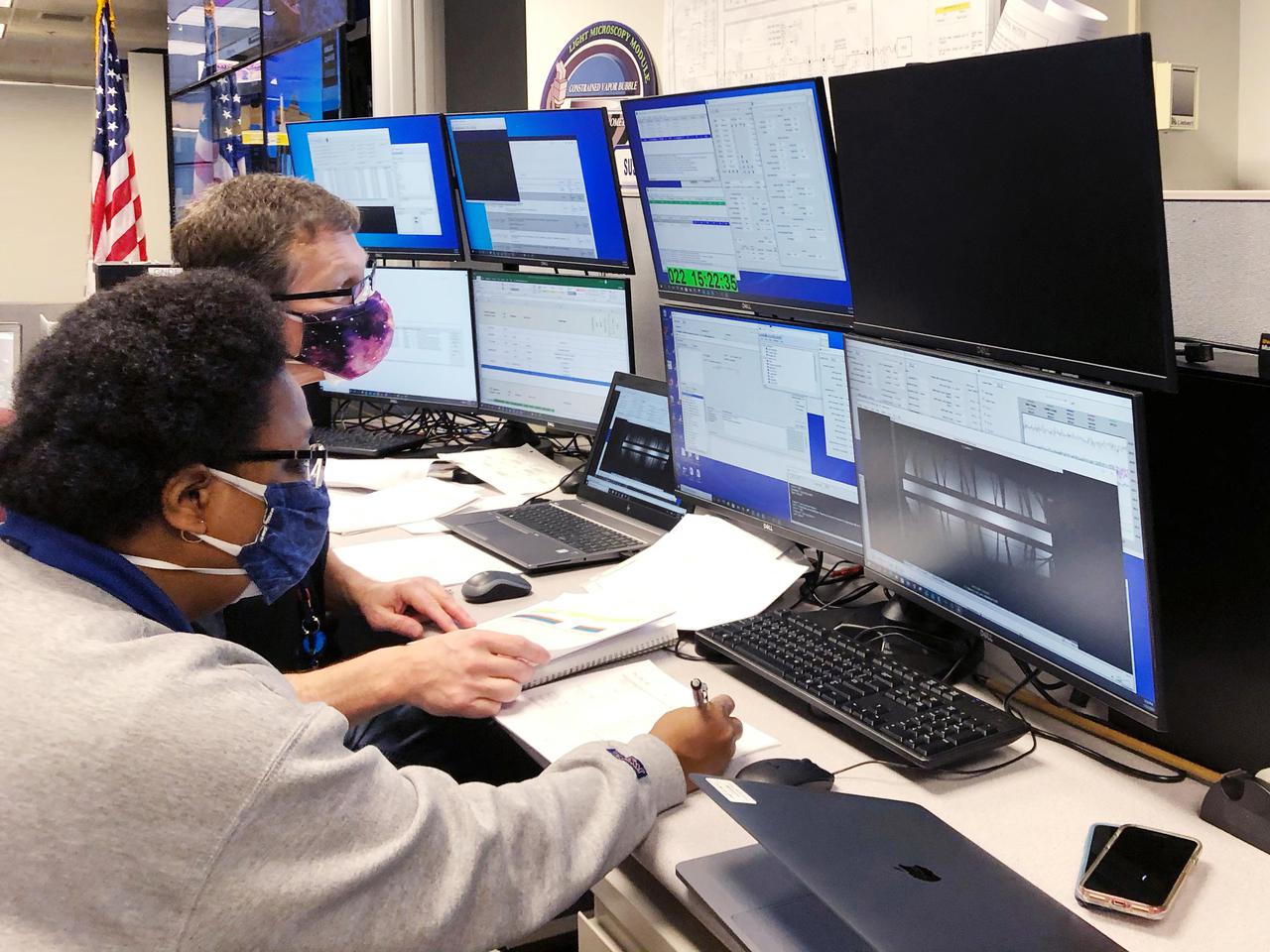
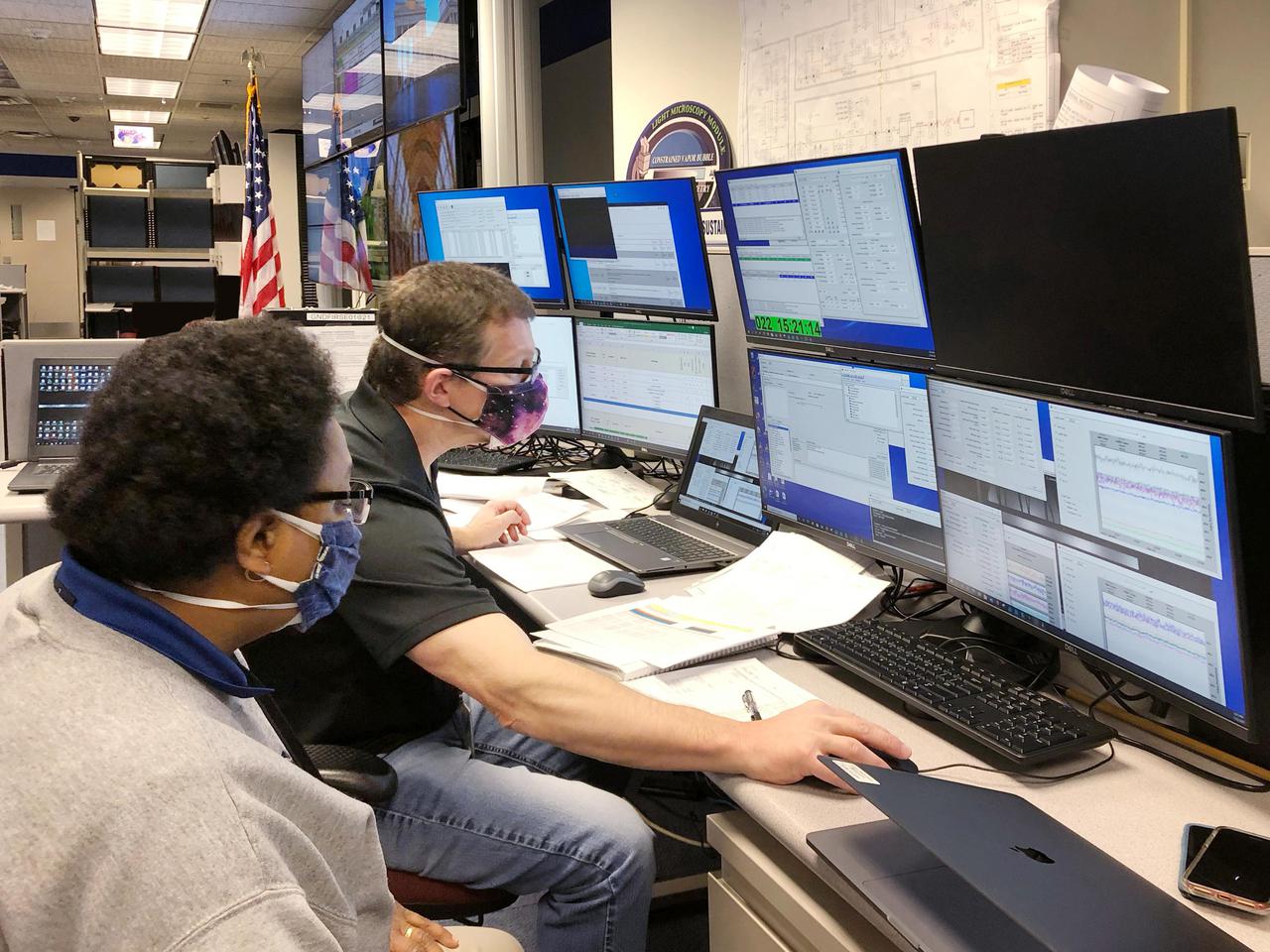
Inside the Launch Control Center’s Firing Room 1 at NASA’s Kennedy Space Center in Florida, members of the Artemis I launch team rehearse the procedures for fueling the Space Launch System (SLS) rocket with super cold propellants, or cryogenics, on Aug. 18, 2020. During the cryogenic simulation, potential problem scenarios were introduced to test the tools, processes, and procedures necessary for fueling the rocket. Artemis I will be the first integrated test flight of SLS and the Orion spacecraft – the system that will ultimately land the first woman and the next man on the Moon by 2024.
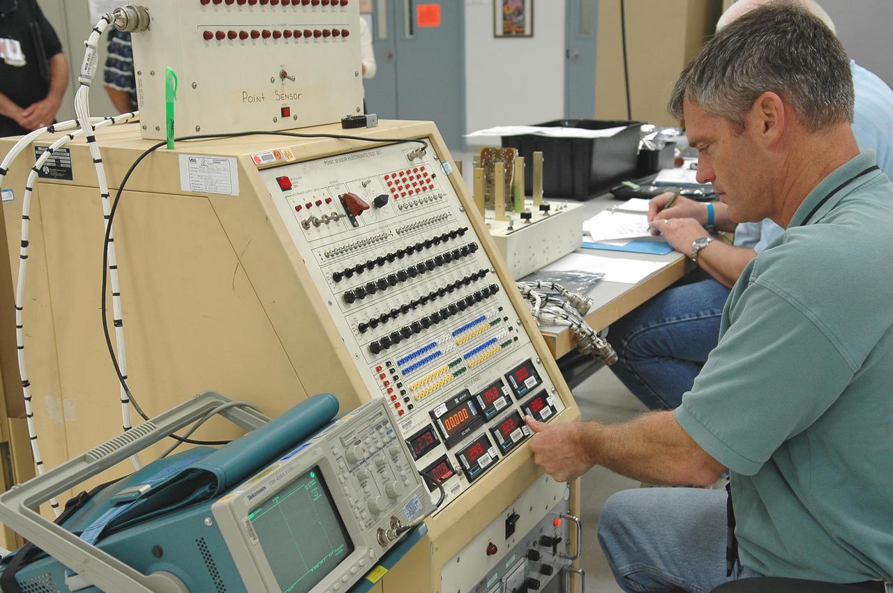
KENNEDY SPACE CENTER, FLA. - Gary King, a test technician, helps test electronic components related to the faulty sensor readings in the liquid hydrogen tank low-level fuel cut-off sensor. The sensor failed a routine prelaunch check during the launch July 13 afternoon, causing mission managers to scrub Discovery's first launch attempt. The sensor protects the Shuttle's main engines by triggering their shutdown in the event fuel runs unexpectedly low. The sensor is one of four inside the liquid hydrogen section of the External Tank (ET).

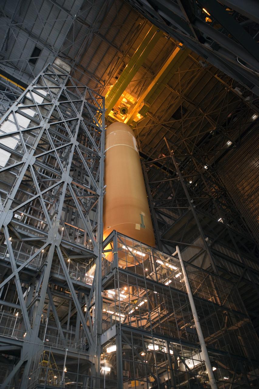
CAPE CANAVERAL, Fla. -- In the Vehicle Assembly Building at NASA's Kennedy Space Center in Florida, External Fuel Tank-122 sits on its transporter in the transfer aisle waiting to be lifted into a test cell. ET-122, the Space Shuttle Program's last external fuel tank was delivered to Kennedy's Turn Basin from NASA’s Michoud Assembly Facility in New Orleans aboard the Pegasus Barge. After testing, ET-122 eventually will be attached to space shuttle Endeavour for the STS-134 mission to the International Space Station targeted to launch February, 2011. For more information visit: http://www.nasa.gov/mission_pages/shuttle/shuttlemissions/sts134/index.html. Photo credit: NASA/Dimitri Gerondidakis
CAPE CANAVERAL, Fla. -- In the Vehicle Assembly Building at NASA's Kennedy Space Center in Florida, External Fuel Tank-122 is being lowered toward a test stand where it will be checked out before launch. ET-122, the Space Shuttle Program's last external fuel tank was delivered to Kennedy's Turn Basin from NASA’s Michoud Assembly Facility in New Orleans aboard the Pegasus Barge. After testing, ET-122 eventually will be attached to space shuttle Endeavour for the STS-134 mission to the International Space Station targeted to launch February, 2011. For more information visit: http://www.nasa.gov/mission_pages/shuttle/shuttlemissions/sts134/index.html. Photo credit: NASA/Dimitri Gerondidakis

Inside the Launch Control Center’s Firing Room 1 at NASA’s Kennedy Space Center in Florida, members of the Artemis I launch team rehearse the procedures for fueling the Space Launch System (SLS) rocket with super cold propellants, or cryogenics, on Aug. 18, 2020. During the cryogenic simulation, potential problem scenarios were introduced to test the tools, processes, and procedures necessary for fueling the rocket. Artemis I will be the first integrated test flight of SLS and the Orion spacecraft – the system that will ultimately land the first woman and the next man on the Moon by 2024.
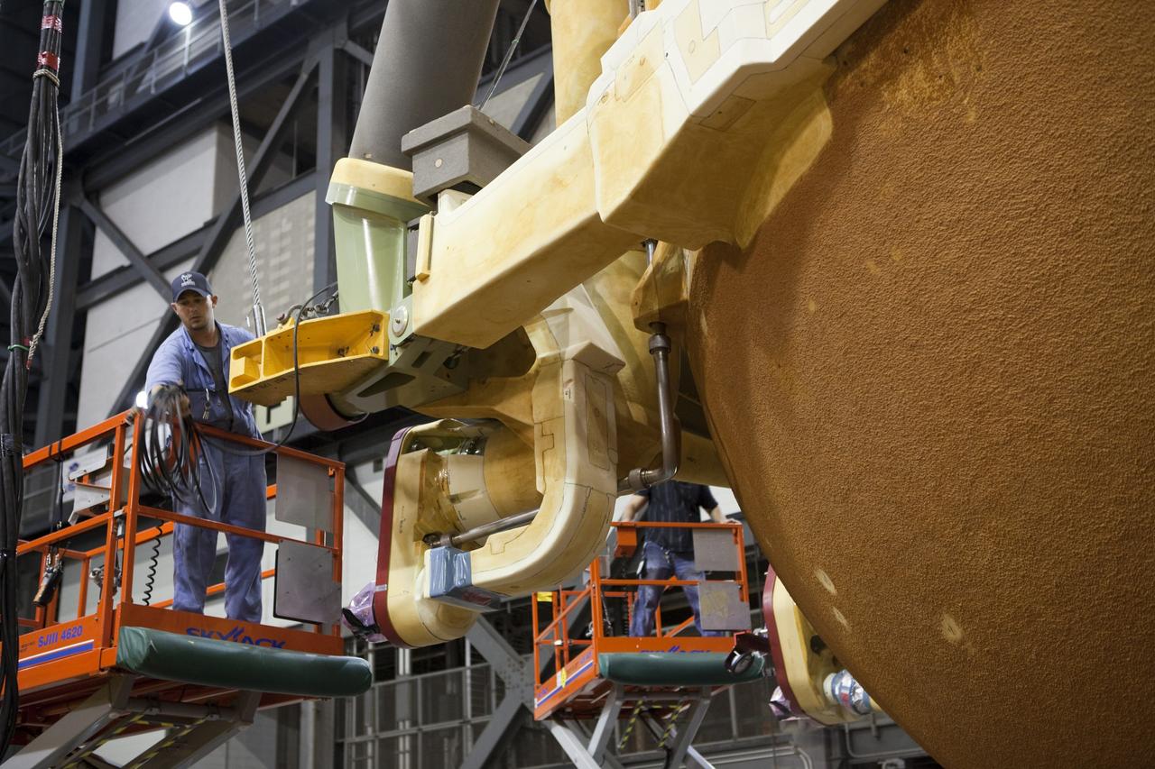
CAPE CANAVERAL, Fla. -- In the Vehicle Assembly Building at NASA's Kennedy Space Center in Florida, workers check the hoist connections on External Fuel Tank-122 as it is lifted toward a test cell. ET-122, the Space Shuttle Program's last external fuel tank was delivered to Kennedy's Turn Basin from NASA’s Michoud Assembly Facility in New Orleans aboard the Pegasus Barge. After testing, ET-122 eventually will be attached to space shuttle Endeavour for the STS-134 mission to the International Space Station targeted to launch February, 2011. For more information visit: http://www.nasa.gov/mission_pages/shuttle/shuttlemissions/sts134/index.html. Photo credit: NASA/Dimitri Gerondidakis

Inside the Launch Control Center’s Firing Room 1 at NASA’s Kennedy Space Center in Florida, members of the Artemis I launch team rehearse the procedures for fueling the Space Launch System (SLS) rocket with super cold propellants, or cryogenics, on Aug. 18, 2020. During the cryogenic simulation, potential problem scenarios were introduced to test the tools, processes, and procedures necessary for fueling the rocket. Artemis I will be the first integrated test flight of SLS and the Orion spacecraft – the system that will ultimately land the first woman and the next man on the Moon by 2024.
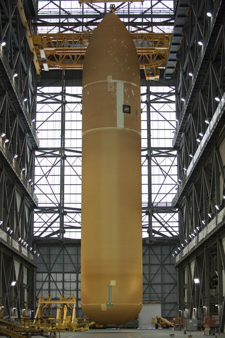
CAPE CANAVERAL, Fla. -- At NASA’s Kennedy Space Center in Florida, External Fuel Tank-122 is suspended vertically over the transfer aisle of the Vehicle Assembly Building as it is lifted toward a test cell. ET-122, the Space Shuttle Program's last external fuel tank was delivered to Kennedy's Turn Basin from NASA’s Michoud Assembly Facility in New Orleans aboard the Pegasus Barge. After testing, ET-122 eventually will be attached to space shuttle Endeavour for the STS-134 mission to the International Space Station targeted to launch February, 2011. For more information visit: http://www.nasa.gov/mission_pages/shuttle/shuttlemissions/sts134/index.html. Photo credit: NASA/Dimitri Gerondidakis

Inside the Launch Control Center’s Firing Room 1 at NASA’s Kennedy Space Center in Florida, members of the Artemis I launch team rehearse the procedures for fueling the Space Launch System (SLS) rocket with super cold propellants, or cryogenics, on Aug. 18, 2020. During the cryogenic simulation, potential problem scenarios were introduced to test the tools, processes, and procedures necessary for fueling the rocket. Artemis I will be the first integrated test flight of SLS and the Orion spacecraft – the system that will ultimately land the first woman and the next man on the Moon by 2024.
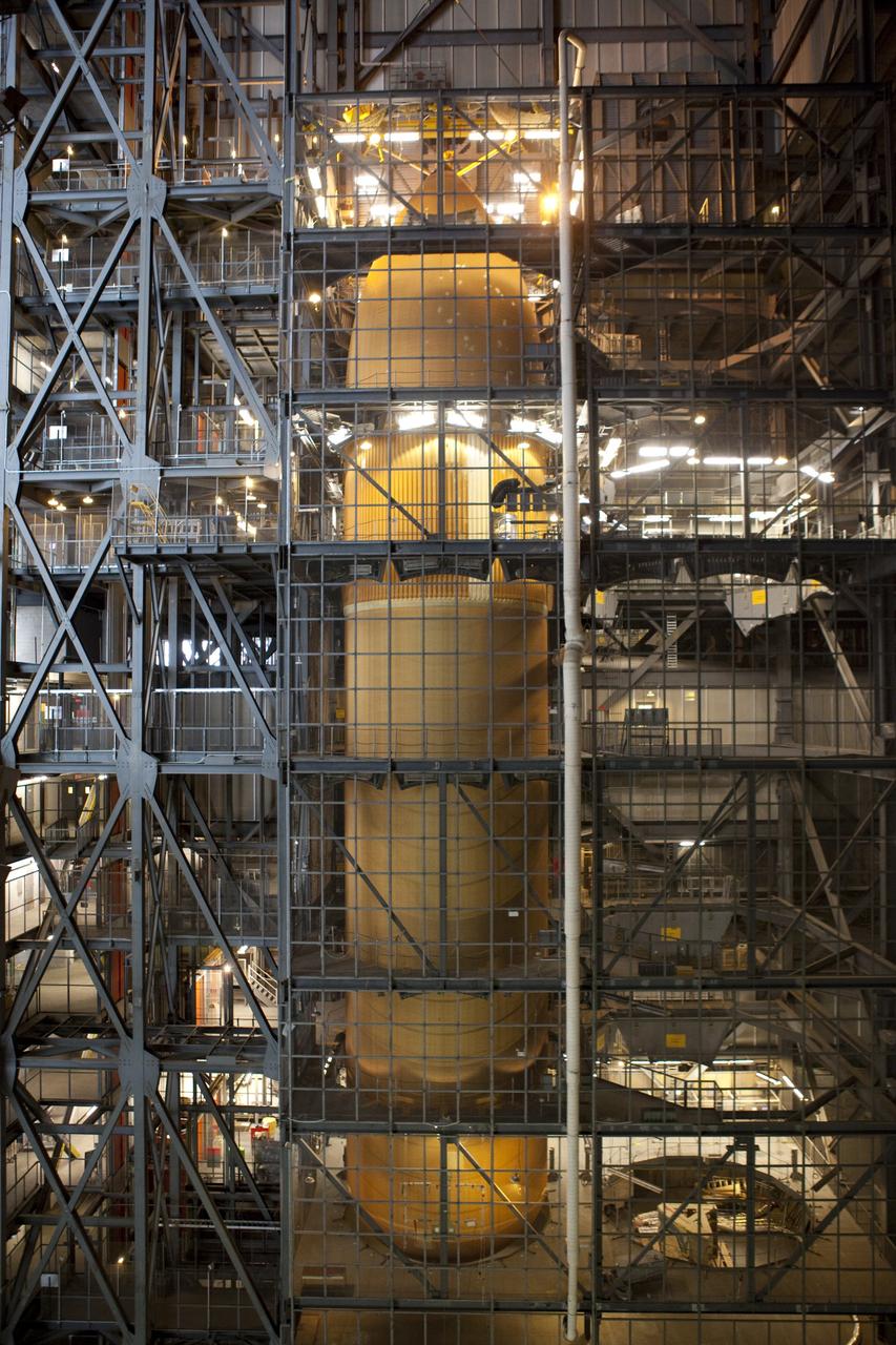
CAPE CANAVERAL, Fla. -- In the Vehicle Assembly Building at NASA's Kennedy Space Center in Florida, External Fuel Tank-122 is being lowered onto a test stand where it will be checked out before launch. ET-122, the Space Shuttle Program's last external fuel tank was delivered to Kennedy's Turn Basin from NASA’s Michoud Assembly Facility in New Orleans aboard the Pegasus Barge. After testing ET-122 eventually will be attached to space shuttle Endeavour for the STS-134 mission to the International Space Station targeted to launch February, 2011. For more information visit: http://www.nasa.gov/mission_pages/shuttle/shuttlemissions/sts134/index.html. Photo credit: NASA/Dimitri Gerondidakis

Inside the Launch Control Center’s Firing Room 1 at NASA’s Kennedy Space Center in Florida, members of the Artemis I launch team rehearse the procedures for fueling the Space Launch System (SLS) rocket with super cold propellants, or cryogenics, on Aug. 18, 2020. During the cryogenic simulation, potential problem scenarios were introduced to test the tools, processes, and procedures necessary for fueling the rocket. Artemis I will be the first integrated test flight of SLS and the Orion spacecraft – the system that will ultimately land the first woman and the next man on the Moon by 2024.
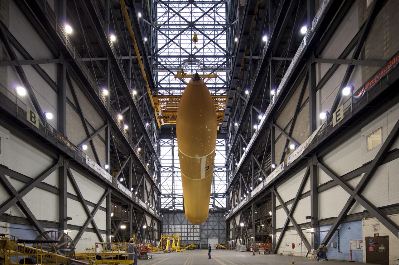
CAPE CANAVERAL, Fla. -- In the Vehicle Assembly Building at NASA's Kennedy Space Center in Florida, workers monitor the progress of External Fuel Tank-122 as it is lifted toward a test cell. ET-122, the Space Shuttle Program's last external fuel tank was delivered to Kennedy's Turn Basin from NASA’s Michoud Assembly Facility in New Orleans aboard the Pegasus Barge. After testing, ET-122 eventually will be attached to space shuttle Endeavour for the STS-134 mission to the International Space Station targeted to launch February, 2011. For more information visit: http://www.nasa.gov/mission_pages/shuttle/shuttlemissions/sts134/index.html. Photo credit: NASA/Dimitri Gerondidakis
CAPE CANAVERAL, Fla. -- In the Vehicle Assembly Building at NASA's Kennedy Space Center in Florida, workers check the hoist connections on External Fuel Tank-122 as it is lifted toward a test cell. ET-122, the Space Shuttle Program's last external fuel tank was delivered to Kennedy's Turn Basin from NASA’s Michoud Assembly Facility in New Orleans aboard the Pegasus Barge. After testing, ET-122 eventually will be attached to space shuttle Endeavour for the STS-134 mission to the International Space Station targeted to launch February, 2011. For more information visit: http://www.nasa.gov/mission_pages/shuttle/shuttlemissions/sts134/index.html. Photo credit: NASA/Dimitri Gerondidakis

CAPE CANAVERAL, Fla. -- In the Vehicle Assembly Building at NASA's Kennedy Space Center in Florida, External Fuel Tank-122 is being lowered toward a test stand where it will be checked out before launch. ET-122, the Space Shuttle Program's last external fuel tank was delivered to Kennedy's Turn Basin from NASA’s Michoud Assembly Facility in New Orleans aboard the Pegasus Barge. After testing, ET-122 eventually will be attached to space shuttle Endeavour for the STS-134 mission to the International Space Station targeted to launch February, 2011. For more information visit: http://www.nasa.gov/mission_pages/shuttle/shuttlemissions/sts134/index.html. Photo credit: NASA/Dimitri Gerondidakis
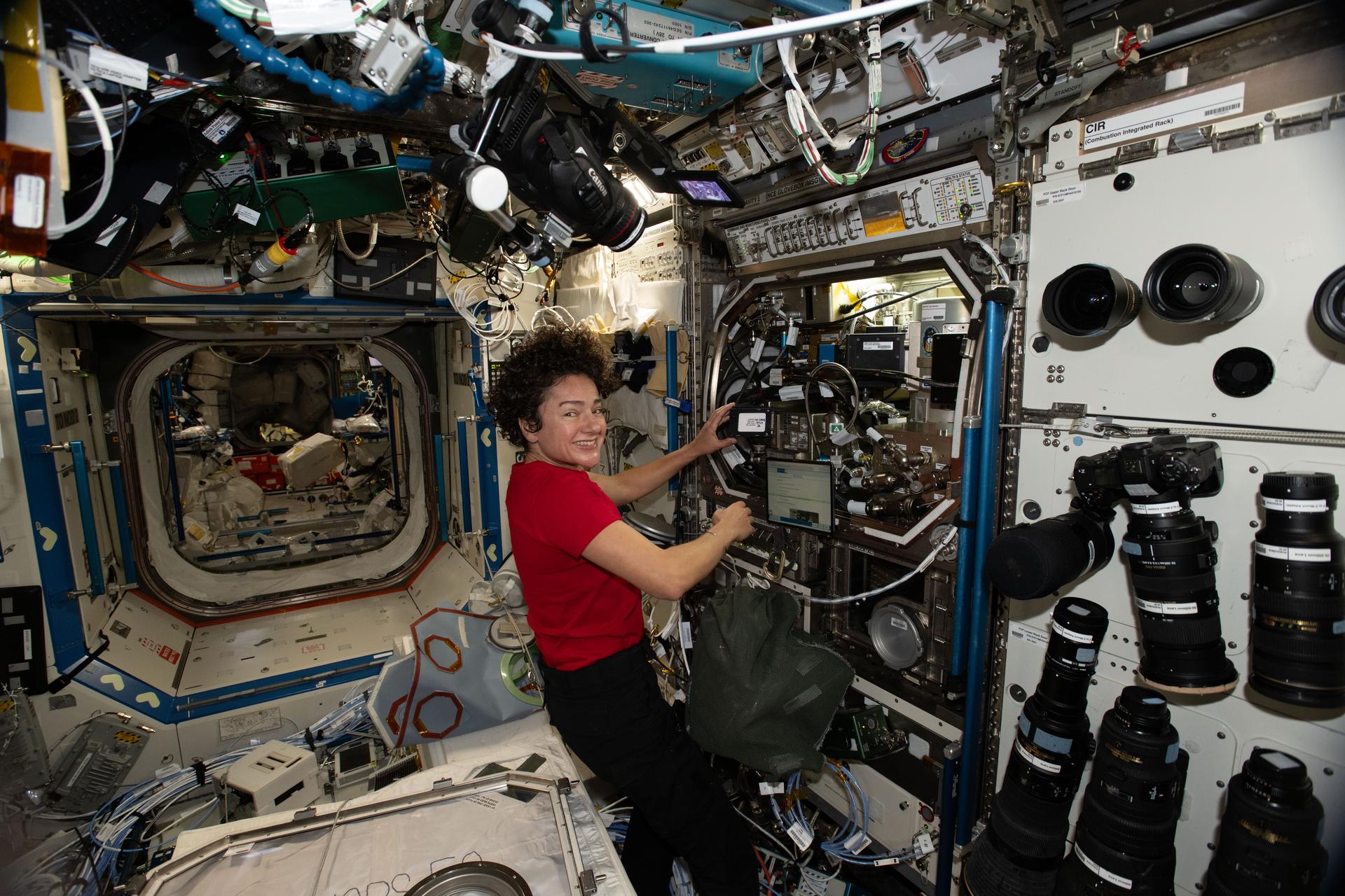
iss074e0314172 (Feb. 16, 2026) --- NASA astronaut and Expedition 74 Flight Engineer Jessica Meir configures the Microgravity Science Glovebox and swaps hard drives to support operations for the Zero Boil-Off Tank physics investigation. The experiment is testing ways to control a spacecraft’s fuel tank pressure due to cryogenic fuel propellants evaporating from the surrounding heat. Credit: NASA/Chris Williams
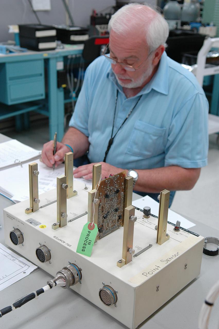
KENNEDY SPACE CENTER, FLA. - Lloyd Pierce, a NASA test engineer, checks electronic components related to the faulty sensor readings in the liquid hydrogen tank low-level fuel cut-off sensor. The sensor failed a routine prelaunch check during the launch July 13, causing mission managers to scrub Discovery's first launch attempt. The sensor protects the Shuttle's main engines by triggering their shutdown in the event fuel runs unexpectedly low. The sensor is one of four inside the liquid hydrogen section of the External Tank (ET).
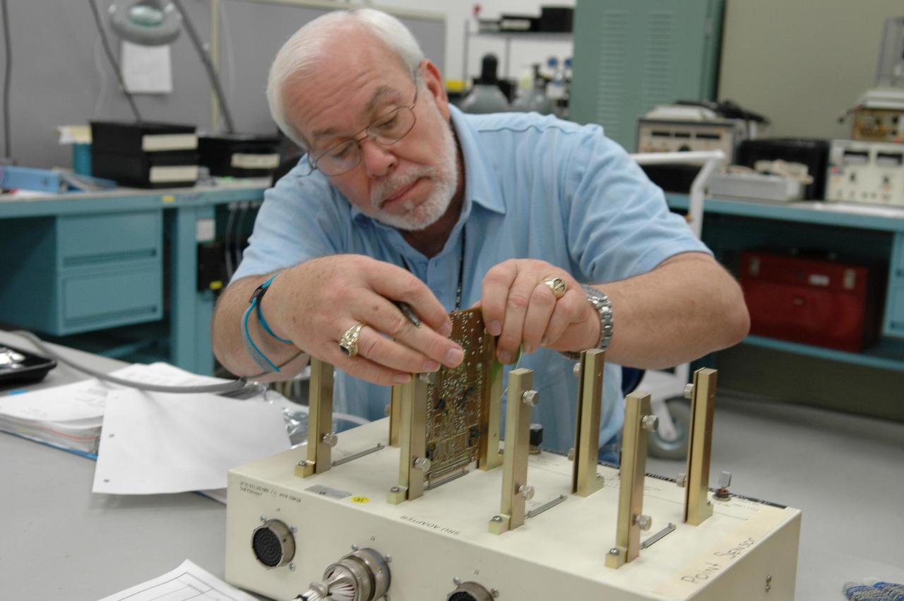
KENNEDY SPACE CENTER, FLA. - Lloyd Pierce, a NASA test engineer, checks electronic components related to the faulty sensor readings in the liquid hydrogen tank low-level fuel cut-off sensor. The sensor failed a routine prelaunch check during the launch July 13, causing mission managers to scrub Discovery's first launch attempt. The sensor protects the Shuttle's main engines by triggering their shutdown in the event fuel runs unexpectedly low. The sensor is one of four inside the liquid hydrogen section of the External Tank (ET).
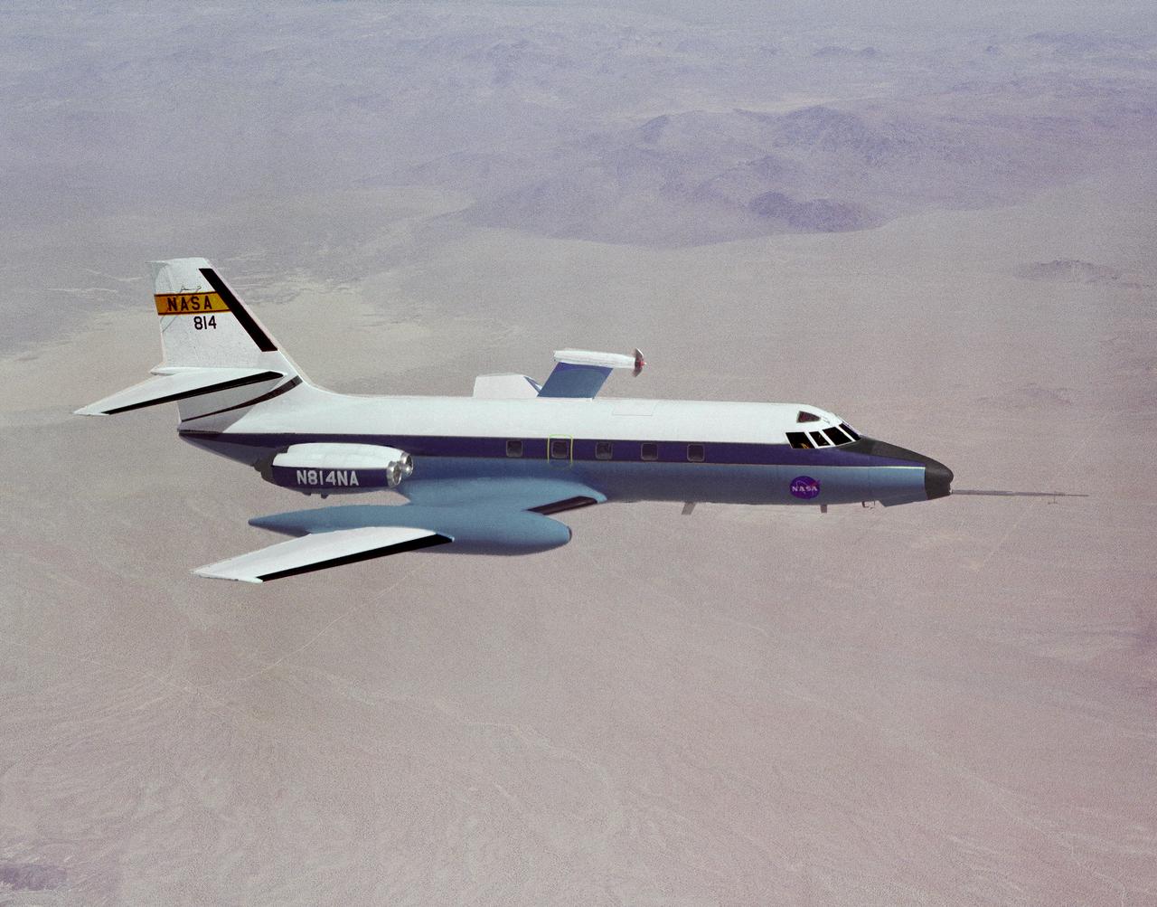
In this photograph, the C-140 JetStar is fitted with a model of a high-speed propeller. Three different designs were tested at NASA's Dryden Flight Research Facility in 1981-1982. Their swept-back blades were intended to increase the speed and fuel efficiency of turboprop aircraft. Speeds of Mach 0.8 were thought possible, while using 20 to 30 percent less fuel than standard jet engines.

KENNEDY SPACE CENTER, FLA. - Lloyd Pierce, a NASA test engineer, checks electronic components related to the faulty sensor readings in the liquid hydrogen tank low-level fuel cut-off sensor. The sensor failed a routine prelaunch check during the launch July 13, causing mission managers to scrub Discovery's first launch attempt. The sensor protects the Shuttle's main engines by triggering their shutdown in the event fuel runs unexpectedly low. The sensor is one of four inside the liquid hydrogen section of the External Tank (ET).
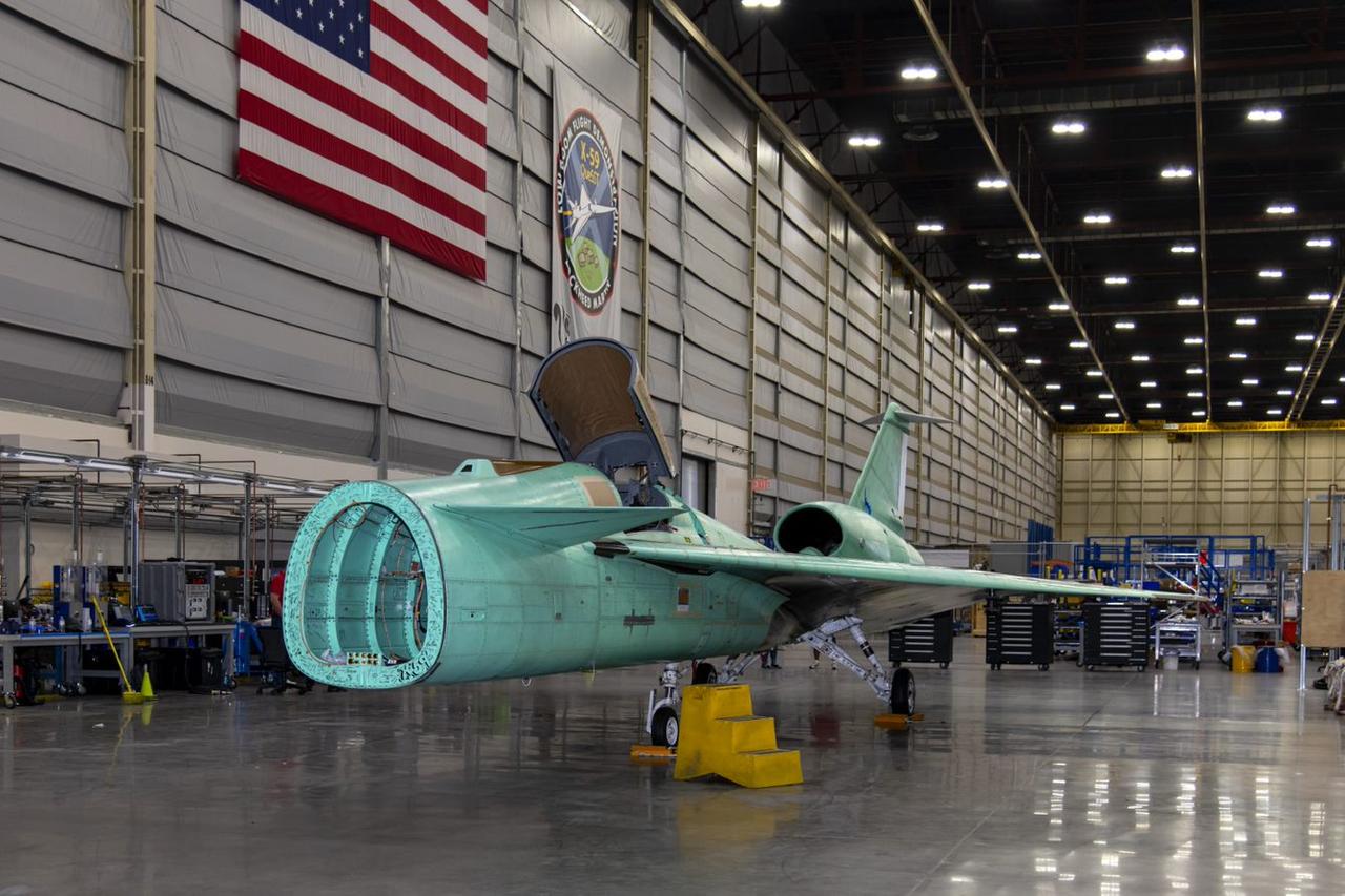
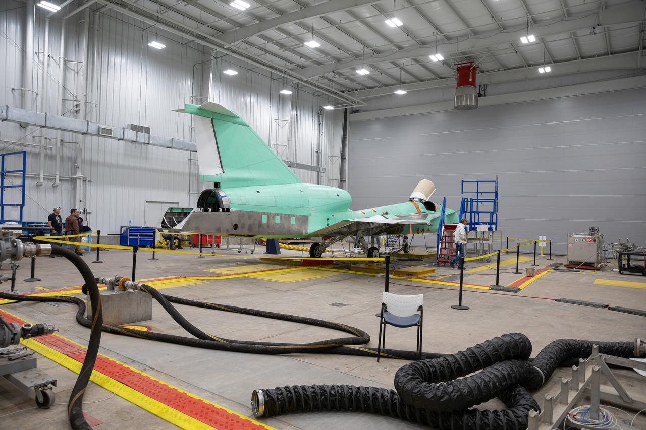
The X-59 arrives home in Palmdale, California after completing important structural and fuel tests at the Lockheed Martin facility in Ft. Worth, Texas. The nose, which is not installed in this image, was removed prior to the transport home and arrived separately to the facility. This is part of NASA’s Quesst mission which plans to help enable supersonic air travel over land.
A panoramic view of NASA’s X-59 in Fort Worth, Texas to undergo structural and fuel testing. The X-59’s nose makes up one third of the aircraft, at 38-feet in length. The X-59 is a one-of-a-kind airplane designed to fly at supersonic speeds without making a startling sonic boom sound for the communities below. This is part of NASA’s Quesst mission which plans to help enable supersonic air travel over land.
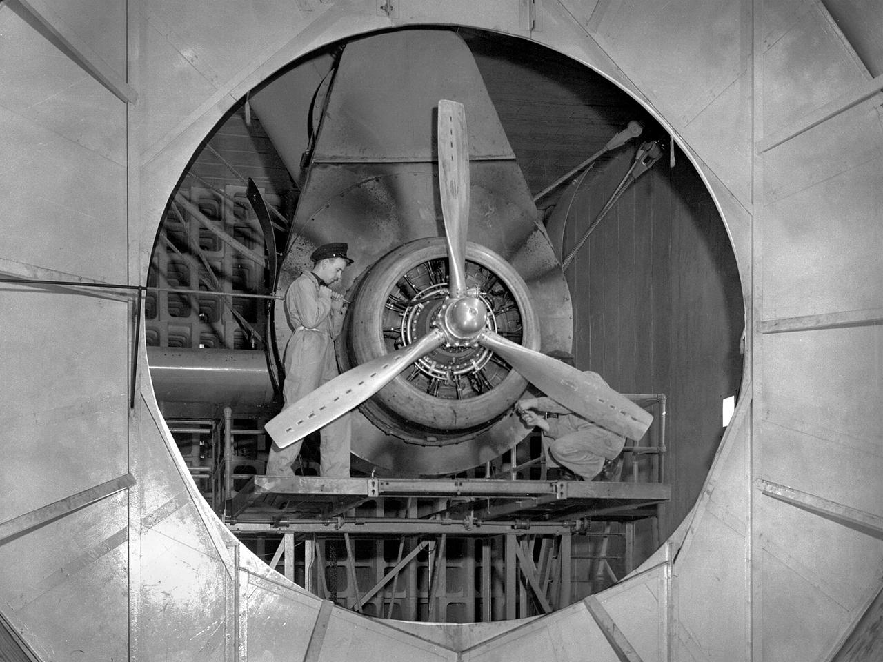
A Wright Aeronautical R–2600 Cyclone piston engine installed in the Engine Propeller Research Building, or Prop House, at the National Advisory Committee for Aeronautics (NACA) Aircraft Engine Research Laboratory. The R–2600 was among the most powerful engines that emerged during World War II. The engine, which was developed for commercial applications in 1939, was used to power the North American B–25 bomber and several other midsize military aircraft. The higher altitudes required by the military caused problems with the engine's cooling and fuel systems. The military requested that the Aircraft Engine Research Laboratory analyze the performance of the R–2600, improve its cooling system, and reduce engine knock. The NACA researchers subjected the engine to numerous tests in its Prop House. The R–2600 was the subject of the laboratory's first technical report, which was written by members of the Fuels and Lubricants Division. The Prop House contained soundproof test cells in which piston engines and propellers were mounted and operated at high powers. Electrically driven fans drew air through ducts to create a stream of cooling air over the engines. Researchers tested the performance of fuels, turbochargers, water-injection and cooling systems here during World War II. The facility was also investigated a captured German V–I buzz bomb during the war.
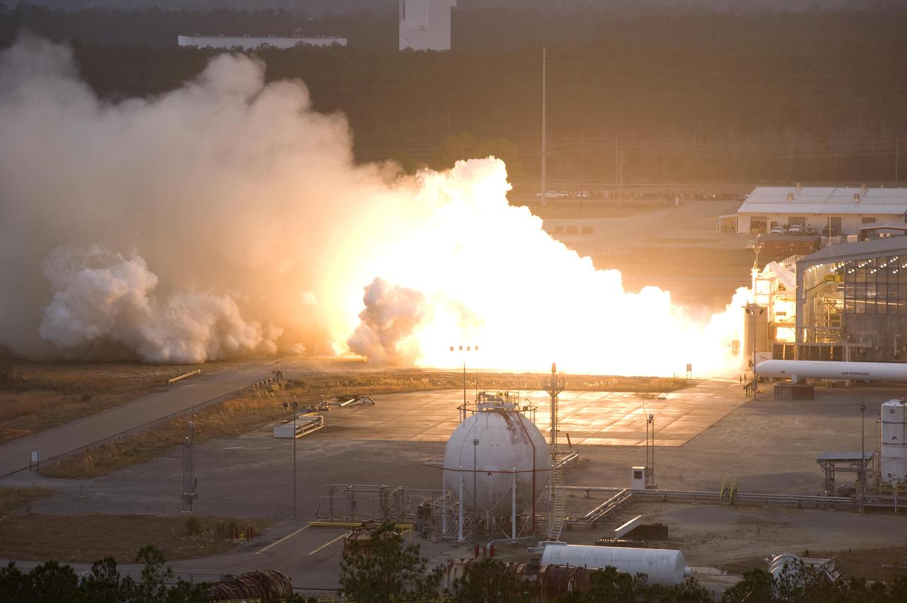
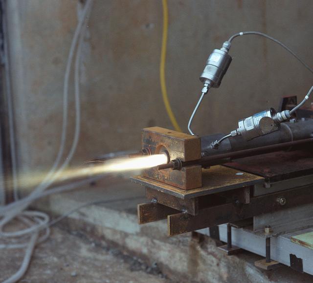
John C. Stennis Space Center engineers conduct a 55-second test fire of Aerojet's liquid-fuel AJ26 rocket engine that will power the first stage of Orbital Sciences Corporation's Taurus II space launch vehicle. The Dec. 17, 2010 test was conducted on the E-1 Test Stand at Stennis in support of NASA's Commercial Transportation Services partnerships to enable commercial cargo flights to the International Space Station. Orbital is under contract with NASA to provide eight cargo missions to the space station through 2015.
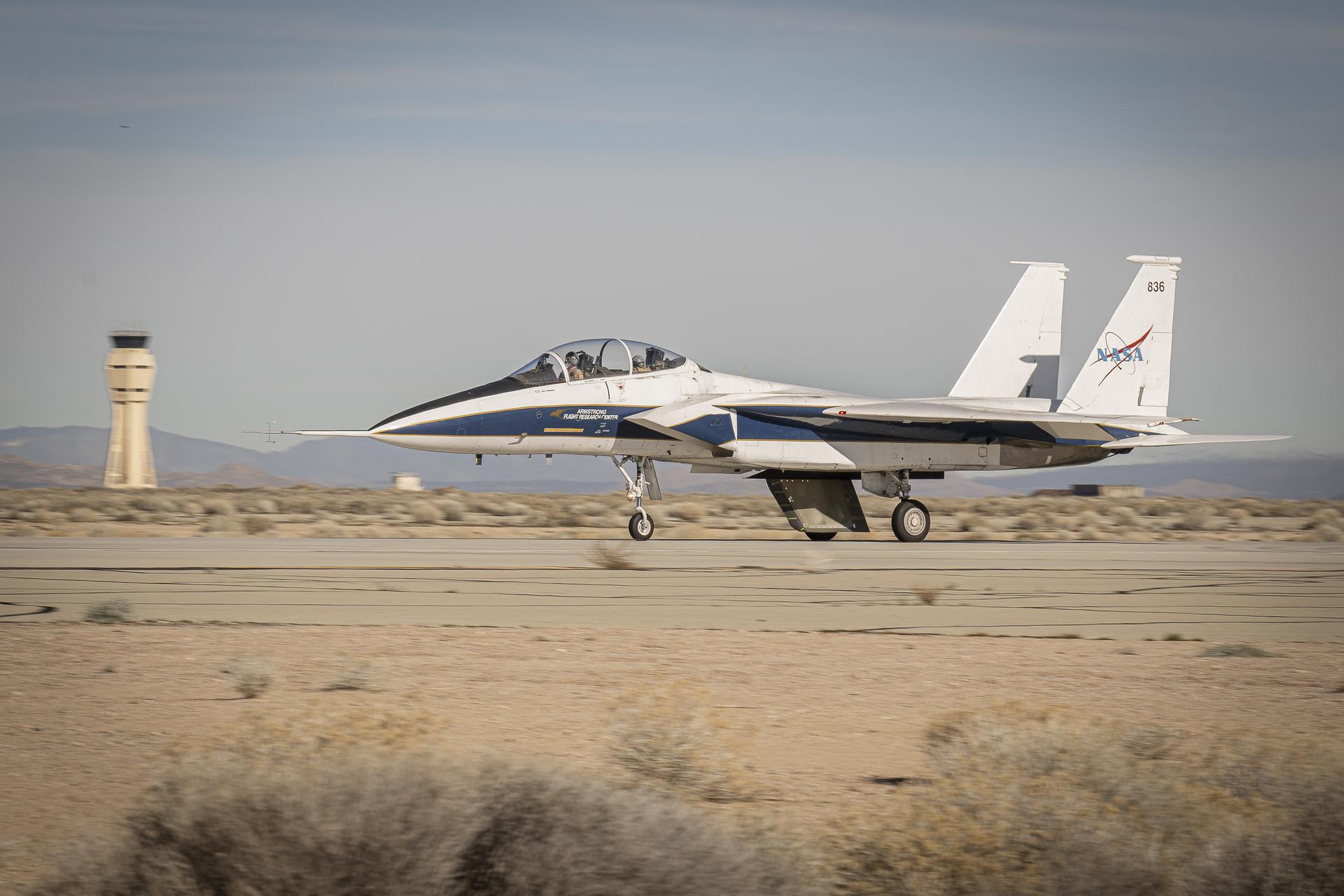
NASA’s Cross Flow Attenuated Natural Laminar Flow (CATNLF) scale model completes its first major milestone – high-speed taxi test – Tuesday, Jan. 12, 2026, at Edwards Air Force Base in California. NASA’s F-15 research aircraft, with the 3-foot-tall test article mounted on its underside, reached speeds of approximately 144 mph during testing. If successful, the technology could be applied to future commercial aircraft to improve efficiency and potentially reduce fuel consumption.
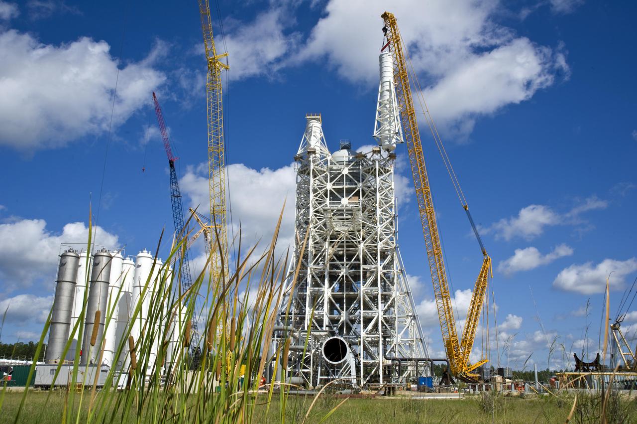
Stennis Space Center employees marked another construction milestone July 25 with installation of the 85,000-gallon liquid hydrogen tank atop the A-3 Test Stand. The 300-foot-tall stand is being built to test next-generation rocket engines that could carry humans into deep space once more. The liquid hydrogen tank and a 35,000-gallon liquid oxygen tank installed atop the steel structure earlier in June will provide fuel propellants for testing the engines.

John C. Stennis Space Center engineers conduct a 55-second test fire of Aerojet's liquid-fuel AJ26 rocket engine that will power the first stage of Orbital Sciences Corporation's Taurus II space launch vehicle. The Dec. 17, 2010 test was conducted on the E-1 Test Stand at Stennis in support of NASA's Commercial Transportation Services partnerships to enable commercial cargo flights to the International Space Station. Orbital is under contract with NASA to provide eight cargo missions to the space station through 2015.
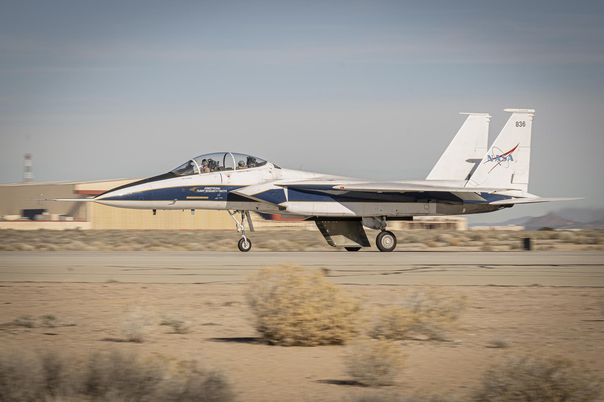
NASA’s Cross Flow Attenuated Natural Laminar Flow (CATNLF) scale model completes its first major milestone – high-speed taxi test – Tuesday, Jan. 12, 2026, at Edwards Air Force Base in California. NASA’s F-15 research aircraft, with the 3-foot-tall test article mounted on its underside, reached speeds of approximately 144 mph during testing. If successful, the technology could be applied to future commercial aircraft to improve efficiency and potentially reduce fuel consumption.
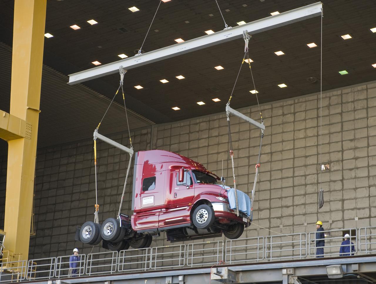
Lawrence Livermore National Labs (LLNL), Navistar and the Department of Energy conduct tests in the NASA Ames National Full-scale Aerodynamic Complex 80x120_foot wind tunnel. The LLNL project is aimed at aerodynamic truck and trailer devices that can reduce fuel consumption at highway speed by 10 percent. Cab being lifted into the tunnel.
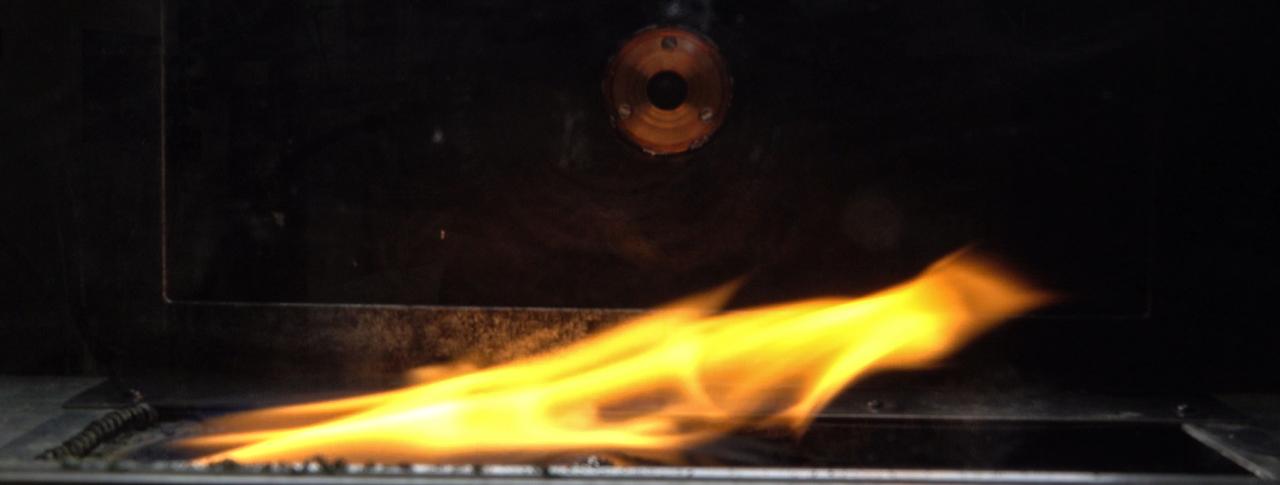
jsc2024e044215 (7/10/2024) --- Side view of spread flame in ground-based test for the Solid Fuel Ignition and Extinction - Oscillatory Flow on Flame Spread (SoFIE-OFFS) investigation. SoFIE-OFFS examines how intermittent or non-steady flame behavior impacts fire spread on Earth. Image courtesy of Worcester Polytechnic Institute.
Marshall Space Flight Center successfully conducted hydrostatic testing on the Saturn V S-IC (first) stage fuel tank. The first stage was powered by five F-1 engines, that used liquid oxygen and kerosene as its propellant.
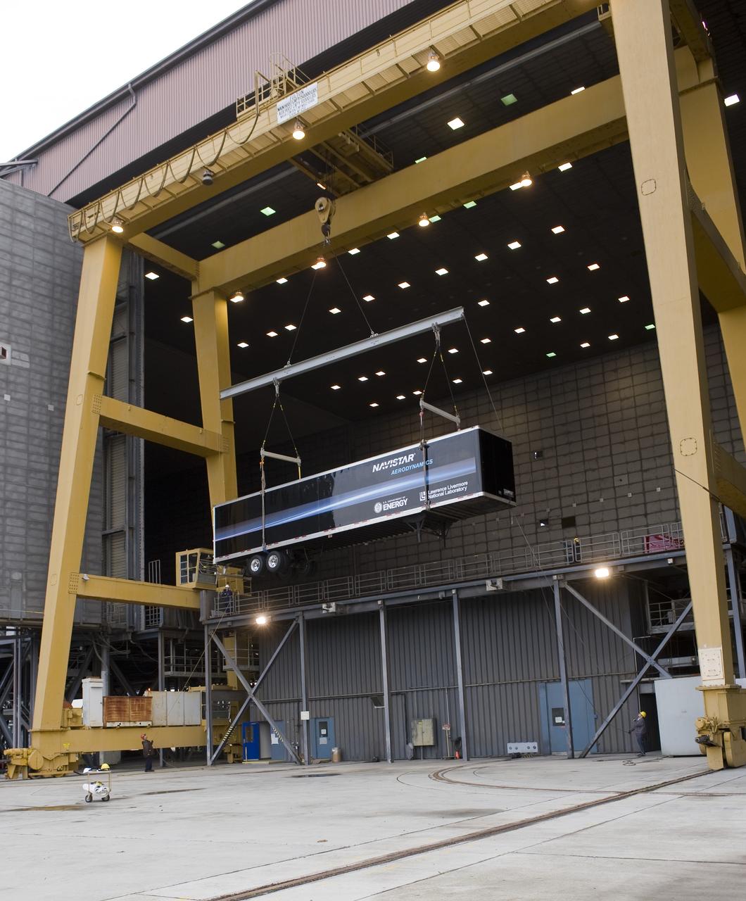
Lawrence Livermore National Labs (LLNL), Navistar and the Department of Energy conduct tests in the NASA Ames National Full-scale Aerodynamic Complex 80x120_foot wind tunnel. The LLNL project is aimed at aerodynamic truck and trailer devices that can reduce fuel consumption at highway speed by 10 percent. Trailer being lifted into the tunnel.

A Fairchild C-82 Packet is purposely destroyed by researchers at the National Advisory Committee for Aeronautics (NACA) Lewis Flight Propulsion Laboratory. In response to an escalating number of transport aircraft crashes in the mid-1940s, the NACA researchers undertook a decade-long investigation into a number of issues surrounding low-altitude aircraft crashes. The tests were conducted at the Ravenna Arsenal, approximately 60 miles south of the Lewis laboratory in Cleveland, Ohio. The aircraft were excess military transports from World War II. The aircraft was guided down the runway at speeds of 80 to 105 miles per hour. It came into contact with poles which tore open the 1500-gallon fuel tanks in the wings before reaching the barriers at the end of the runway. Fuel poured from the tanks and supply lines, resulting in the spread of both liquid fuel and a large cloud of spray. Solomon Weiss developed a method of dying the fuel red to improve its visibility during the crashes. This red fuel cloud trailed slightly behind the skidding aircraft, then rushed forward when the aircraft stopped. The nine-crash initial phase of testing used Lockheed C-56 Lodestar and C-82 transport aircraft to identify potential ignition sources and analyze the spread of flammable materials. The researchers were able to identify different classes of ignition sources, fuel disbursement patterns, the time when a particular ignition source might appear, rate of the fire spread, cabin survival times, and deceleration rates.
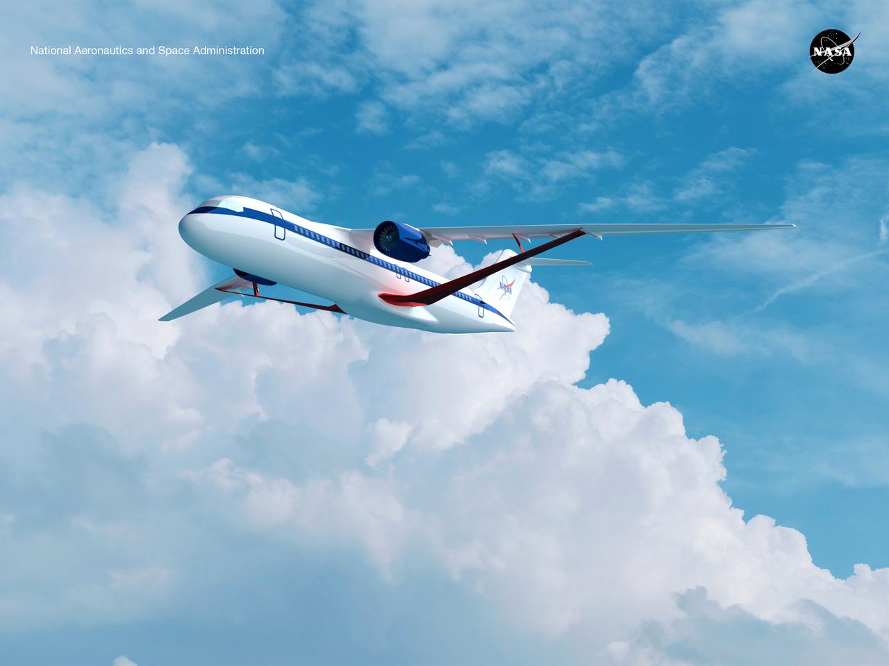
Notice anything different about the wings on this airliner? This conceptual truss-braced wing narrowbody is an aircraft with a 170ft span folding wing. By utilizing trusses, the aircraft can have longer, thinner wings with greater aspect ratios. This, in turn, translates into less drag and 5-10% less fuel burned. The Transonic Truss-Braced Wing aircraft originated from a joint effort by NASA and Boeing to develop subsonic commercial transport concepts – meeting NASA-defined metrics in terms of reduced noise, emissions, and fuel consumption. The design is currently undergoing wind tunnel testing and other studies by NASA researchers.