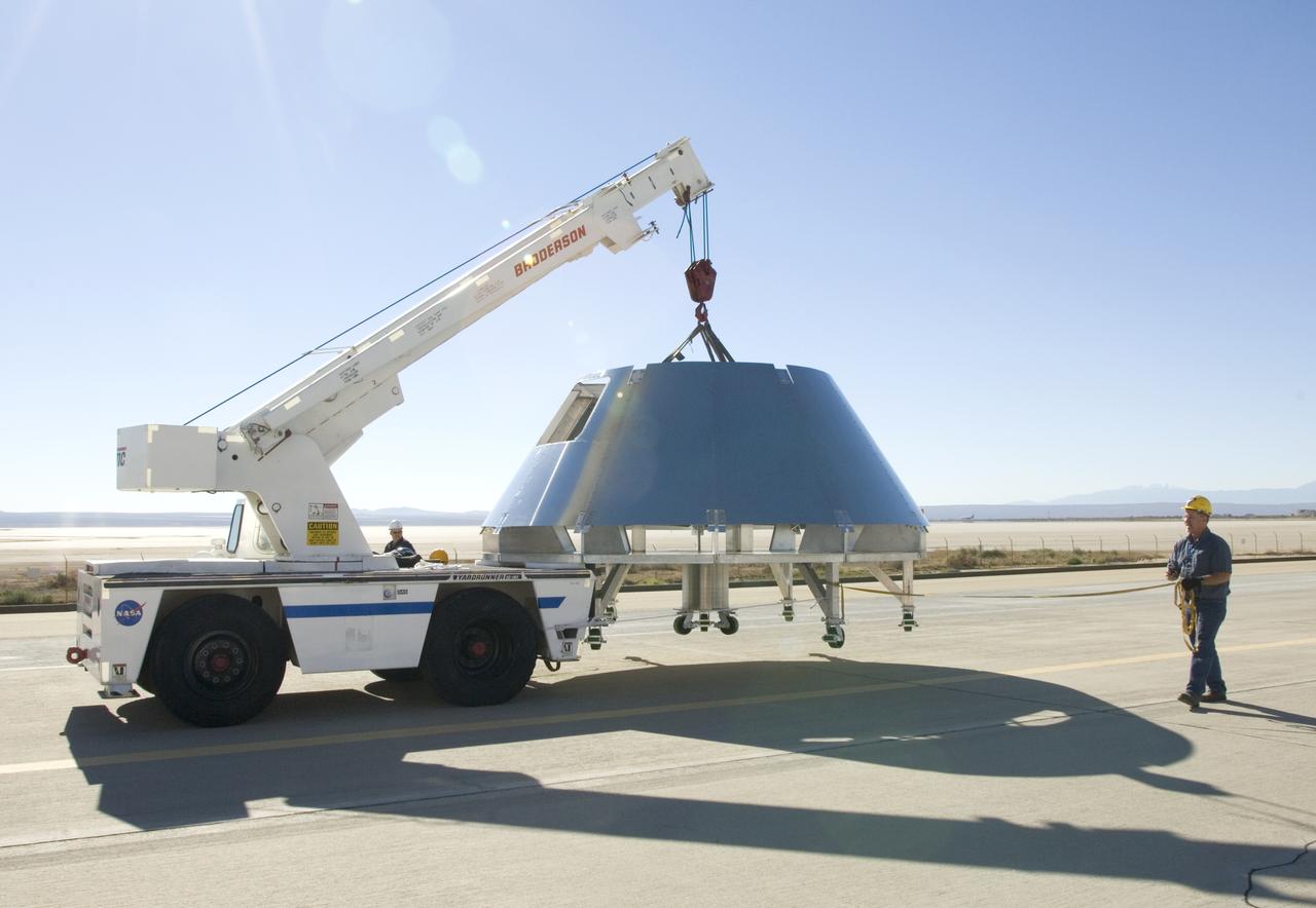
Rogers Dry Lake serves as a backdrop for a mockup Orion crew module built by NASA Dryden Flight Research Center's Fabrication Branch. The module was relocated to Dryden's Shuttle hangar on Sept. 25, 2007.
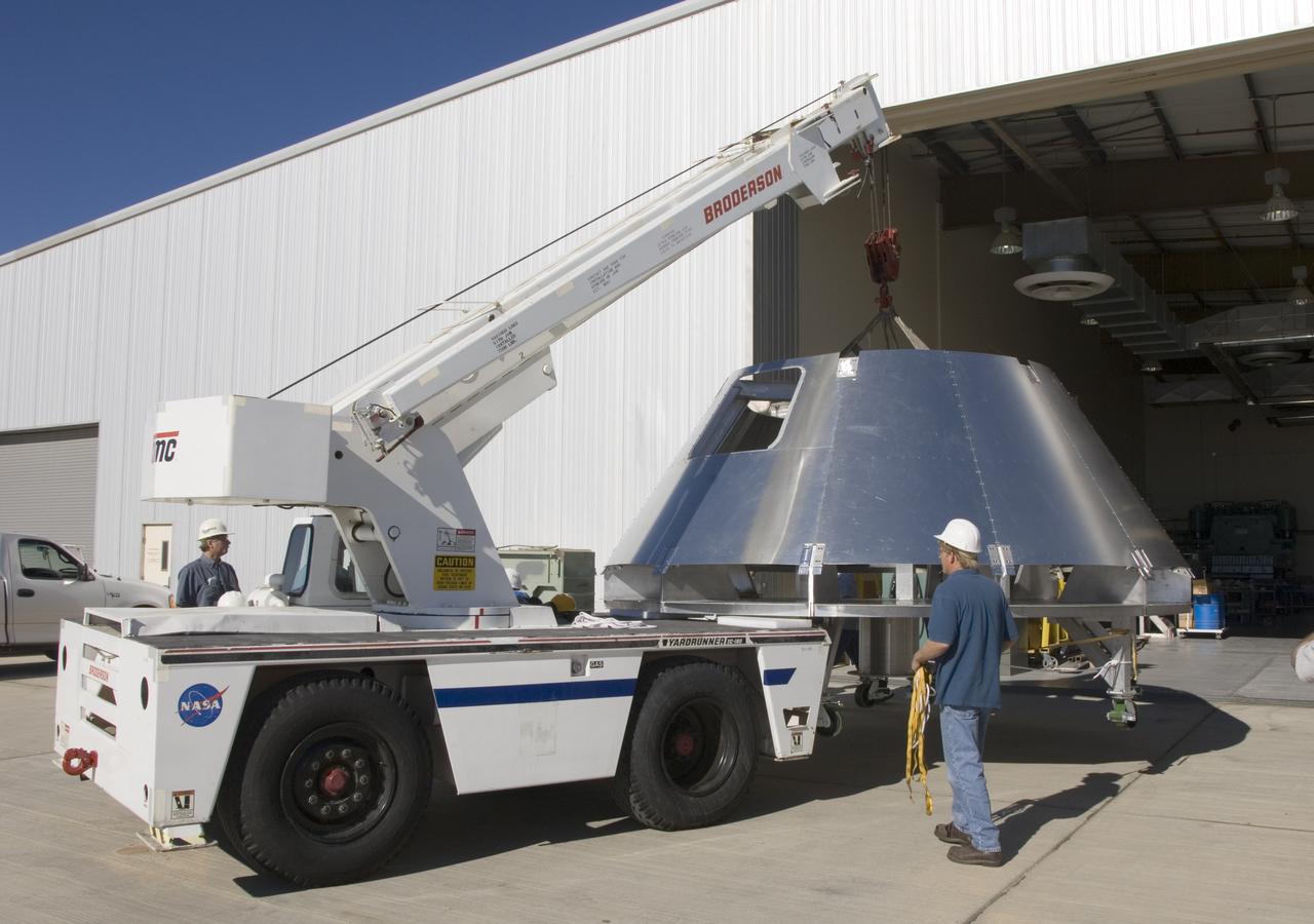
A mockup Orion crew module built by NASA Dryden Flight Research Center's Fabrication Branch gets a lift from its construction site to its new home in Dryden's Shuttle hangar.

NASA Dryden technicians take measurements inside a fit-check mockup for prior to systems installation on a boilerplate Orion launch abort test crew capsule. A mockup Orion crew module has been constructed by NASA Dryden Flight Research Center's Fabrication Branch. The mockup is being used to develop integration procedures for avionics and instrumentation in advance of the arrival of the first abort flight test article.
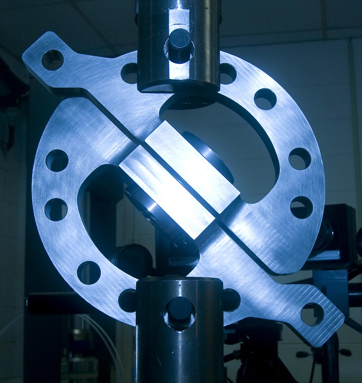
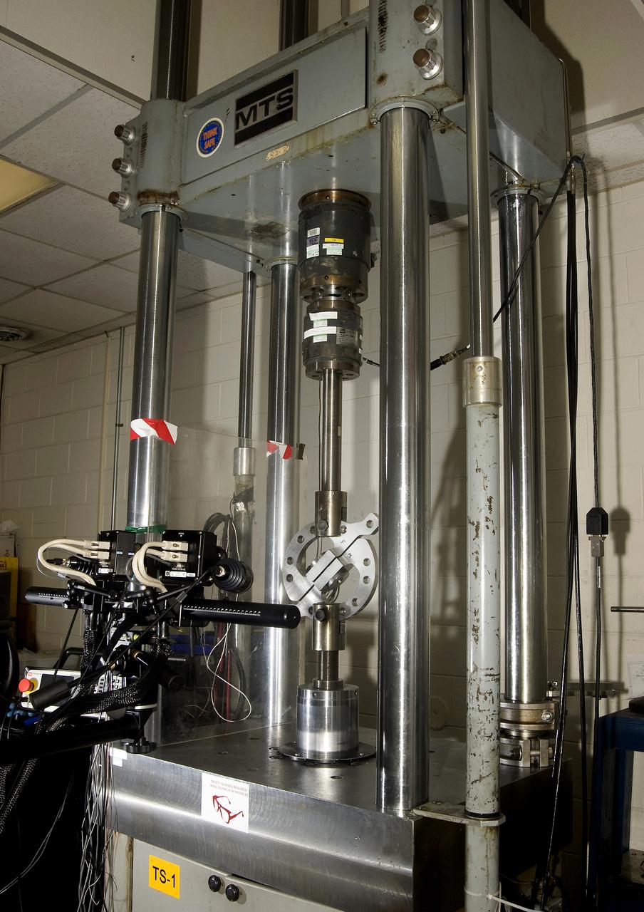
DEVELOPMENT TESTING BEING CONDUCTED AT THE REQUEST OF THE MSFC DYNAMICS, LOADS, AND STRENGTH BRANCH (EV31) TO STUDY THE FAILURE BEHAVIOR OF FASTENERS SUBJECTED TO COMBINED SHEAR AND TENSION LOADING. THE DATA FROM THIS TESTING WILL BE USED TO DEVELOP APPROPRIATE STRUCTURAL ANALYSIS METHODS AS PART OF A FASTENER STANDARDS EFFORT SPONSORED BY THE NASA ENGINEERING SAFETY CENTER (NESC). THE TEST FIXTURE WAS DESIGNED AND FABRICATED THROUGH THE MSFC MECHANICAL FABRICATION BRANCH (ES23). THE TESTING ORGANIZATION IS THE MSFC MATERIALS TEST BRANCH (EM10).
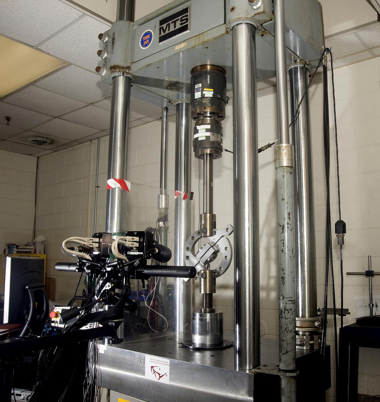
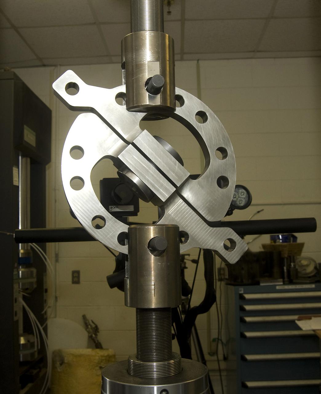
DEVELOPMENT TESTING BEING CONDUCTED AT THE REQUEST OF THE MSFC DYNAMICS, LOADS, AND STRENGTH BRANCH (EV31) TO STUDY THE FAILURE BEHAVIOR OF FASTENERS SUBJECTED TO COMBINED SHEAR AND TENSION LOADING. THE DATA FROM THIS TESTING WILL BE USED TO DEVELOP APPROPRIATE STRUCTURAL ANALYSIS METHODS AS PART OF A FASTENER STANDARDS EFFORT SPONSORED BY THE NASA ENGINEERING SAFETY CENTER (NESC). THE TEST FIXTURE WAS DESIGNED AND FABRICATED THROUGH THE MSFC MECHANICAL FABRICATION BRANCH (ES23). THE TESTING ORGANIZATION IS THE MSFC MATERIALS TEST BRANCH (EM10).
DEVELOPMENT TESTING BEING CONDUCTED AT THE REQUEST OF THE MSFC DYNAMICS, LOADS, AND STRENGTH BRANCH (EV31) TO STUDY THE FAILURE BEHAVIOR OF FASTENERS SUBJECTED TO COMBINED SHEAR AND TENSION LOADING. THE DATA FROM THIS TESTING WILL BE USED TO DEVELOP APPROPRIATE STRUCTURAL ANALYSIS METHODS AS PART OF A FASTENER STANDARDS EFFORT SPONSORED BY THE NASA ENGINEERING SAFETY CENTER (NESC). THE TEST FIXTURE WAS DESIGNED AND FABRICATED THROUGH THE MSFC MECHANICAL FABRICATION BRANCH (ES23). THE TESTING ORGANIZATION IS THE MSFC MATERIALS TEST BRANCH (EM10).
DEVELOPMENT TESTING BEING CONDUCTED AT THE REQUEST OF THE MSFC DYNAMICS, LOADS, AND STRENGTH BRANCH (EV31) TO STUDY THE FAILURE BEHAVIOR OF FASTENERS SUBJECTED TO COMBINED SHEAR AND TENSION LOADING. THE DATA FROM THIS TESTING WILL BE USED TO DEVELOP APPROPRIATE STRUCTURAL ANALYSIS METHODS AS PART OF A FASTENER STANDARDS EFFORT SPONSORED BY THE NASA ENGINEERING SAFETY CENTER (NESC). THE TEST FIXTURE WAS DESIGNED AND FABRICATED THROUGH THE MSFC MECHANICAL FABRICATION BRANCH (ES23). THE TESTING ORGANIZATION IS THE MSFC MATERIALS TEST BRANCH (EM10).
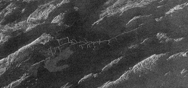
This image from NASA Magellan spacecraft covers region near Hestia Rupes on the northwestern corner of Aphrodite Terra. The complex network of narrow (<1 kilometer) fractures in the center of the image extends for approximately 50 kilometers (31 miles). This network exhibits tributary-like branches similar to those observed in river systems on Earth. However, the angular intersections of tributaries suggest tectonic control. These features appear to be due to drainage of lava along preexisting fractures and subsequent collapse of the surface. The underlying tectonic fabric can be observed in the northeast trending ridges which predate the plains. http://photojournal.jpl.nasa.gov/catalog/PIA00469
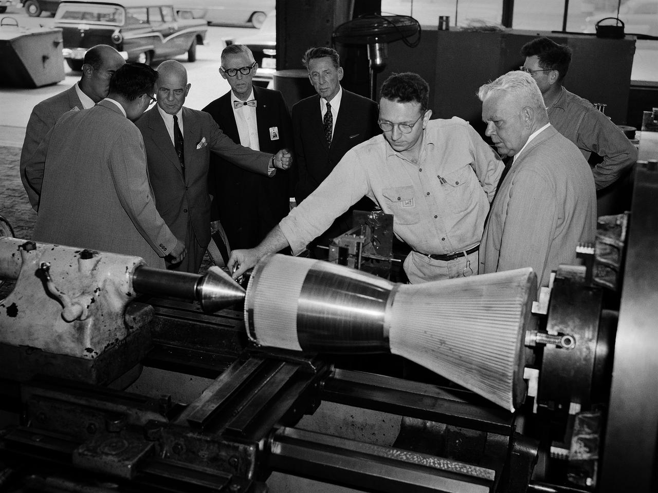
National Advisory Committee for Aeronautics (NACA) Chairman James Doolittle and Thompson Products Chairman of the Board Frederick Crawford receive a tour of the Lewis Flight Propulsion Laboratory during the last few months of the NACA. Lewis mechanic Leonard Tesar demonstrates the machining of a 20,000-pound thrust rocket engine for the group in the Fabrication Shop. From left to right, Associate Director Eugene Manganiello, researcher Edward Baehr, Doolittle, NACA Executive Secretary John Victory, Crawford, Tesar, Lewis Director Raymond Sharp, and mechanic Curtis Strawn. Doolittle began his career as a test pilot and air racer. In 1942 he famously flew a B-25 Mitchell on a daring raid over Tokyo. Doolittle also worked with the aviation industry on the development of aircraft fuels and instrumentation. After the war he served as vice president of Shell Oil and as a key government advisor. In this capacity he also served on the NACA’s Executive Committee for a number of years and served as its Chairman in 1957 and 1958. Tesar was a supervisor at the Sheet Metal Shop in the Fabrication Building. He joined the laboratory in 1948 and enrolled in their Apprentice Program. He graduated from the school three years later as an aviation metalsmith. The Fabrication Branch created a wide variety of hardware for the laboratory’s research projects. Requests from research divisions ranged from sheetmetal manufacturing for aircraft to fabrication of rocket engines. Tesar retired in 1982 after 37 years of service.
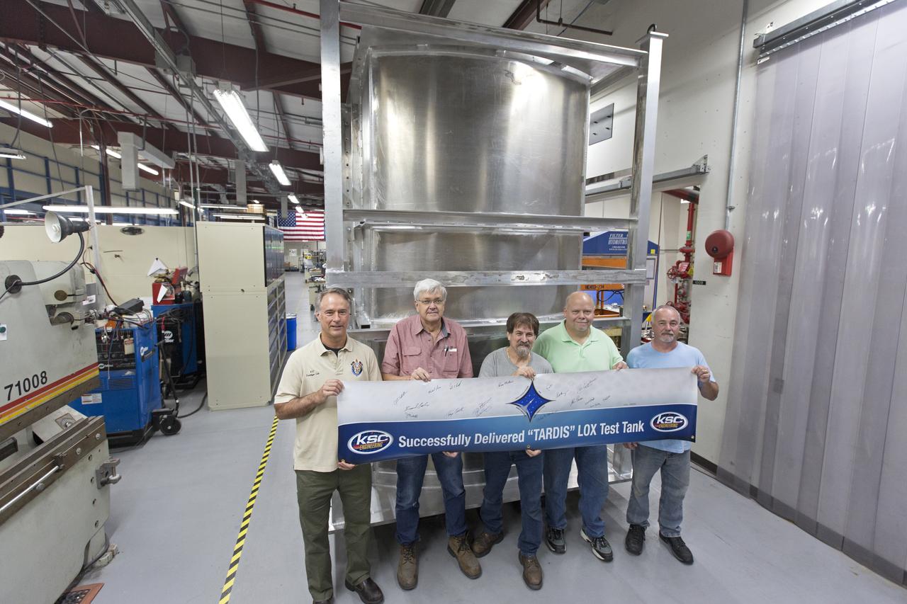
Inside the Prototype Development Laboratory at NASA's Kennedy Space Center in Florida, engineers and technicians hold a banner marking the successful delivery of a liquid oxygen test tank called Tardis. From left, are Todd Steinrock, chief, Fabrication and Development Branch, Prototype Development Lab; David McLaughlin, electrical engineering technician; Phil Stroda, mechanical engineering technician; Perry Dickey, lead electrical engineering technician; and Harold McAmis, lead mechanical engineering technician. Engineers and technicians worked together to develop the tank and build it at the lab to support cryogenic testing at Johnson Space Center's White Sands Test Facility in Las Cruces, New Mexico. The 12-foot-tall, 3,810-pound aluminum tank will be shipped to White Sands for testing.
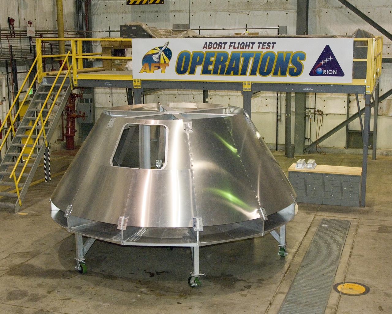
NASA Dryden's mockup Orion crew module is located in Dryden's Shuttle hangar, where abort flight test equipment is being positioned.
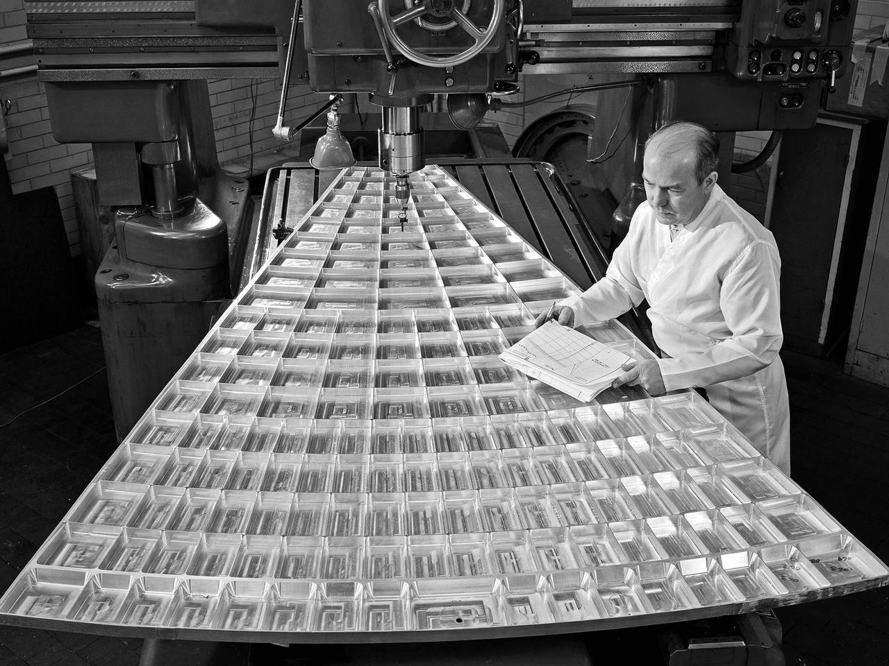
Daniel Bernatowicz, Chief of the Advanced Power Systems Branch at the National Aeronautics and Space Administration (NASA) Lewis Research Center, examines a 20-foot section of a solar mirror being fabricated in the Jig Bore Room of the Technical Services Building. NASA Lewis was conducting a wide-ranging effort to explore methods of generating electrical power for spacecraft. One method employed a large parabolic mirror to concentrate the sun’s energy. The mirror had to remain rigid and withstand micrometeoroids, but remain light and compact enough to be easily launched. In 1963 Bernatowicz and his researchers undertook a program to design a solar mirror to work with the Brayton cycle system on a space station. The mirror in this photograph was prepared for a conference on Advanced Technology in Space Power Systems held at Lewis in late August 1966. Lewis experts discussed advances with batteries, fuel cells, isotope and thermoelectric generators, and the SNAP-8 space power system. Lewis was developing several types of solar mirrors to work with a Brayton cycle electric generating system. The mirror’s 12 sections were shaped using a unique forming process developed at Lewis, coated with an epoxy, and plated with aluminum. The mirror concentrated the Sun's rays on a heat storage receiver containing lithium fluoride. This material was heated to produce power in a turbogenerator system, while additional heat was stored for use when the unit was in the Earth's shadow.