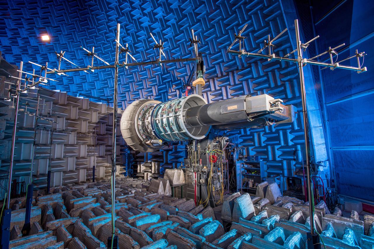
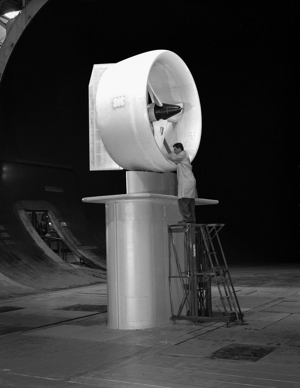
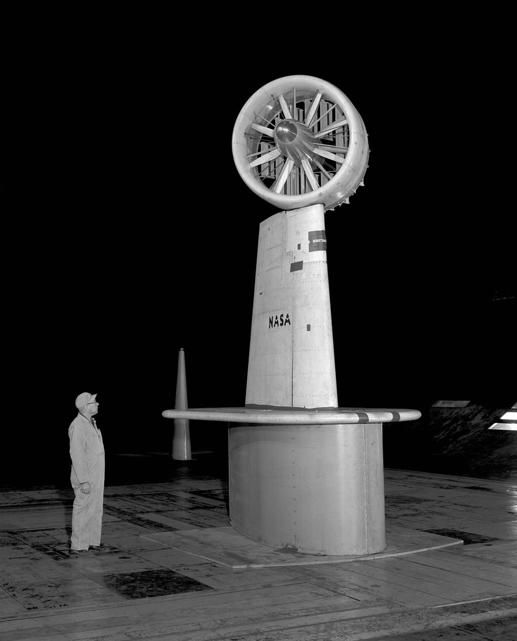
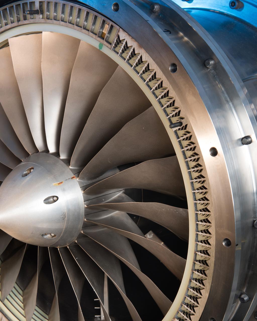
The Advanced Noise Control Fan shown here is located in NASA Glenn’s Aero-Acoustic Propulsion Laboratory. The 4-foot diameter fan is used to evaluate innovate aircraft engine noise reduction concepts less expensively and more quickly.
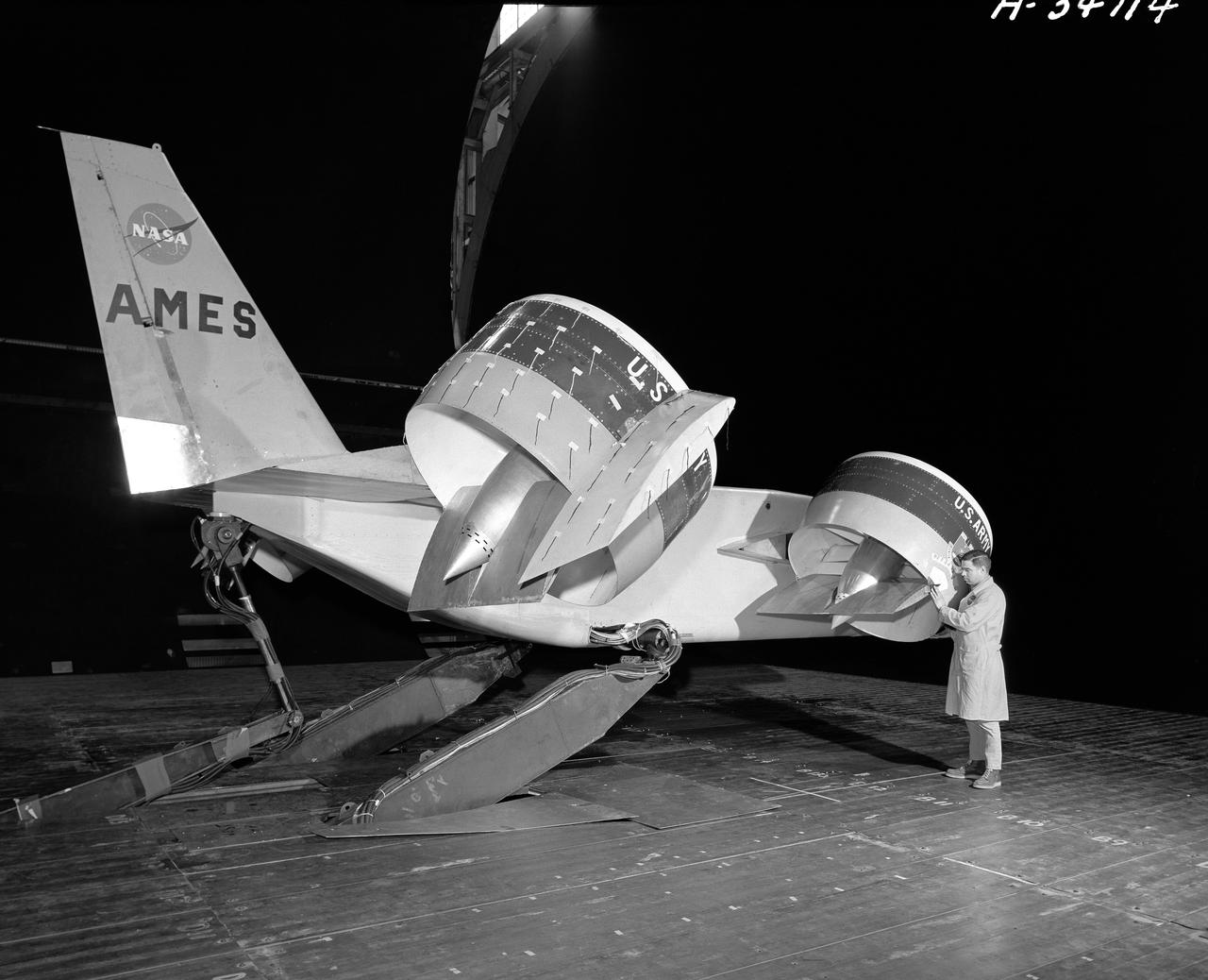
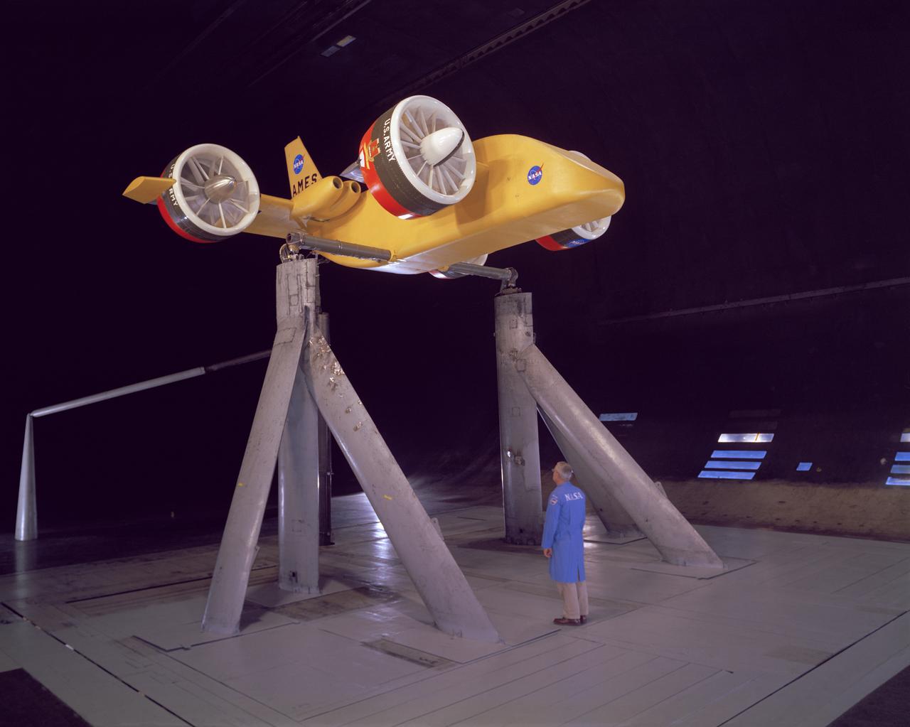
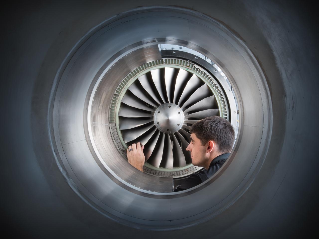
Tandem dual ducted fan mounted on ground plane on varriable height struts, 3/4 front view
Field of Fans
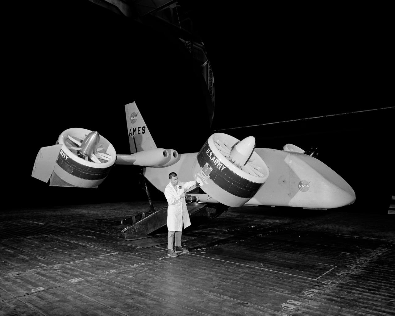
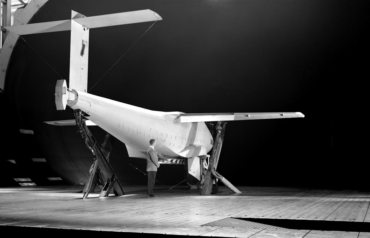
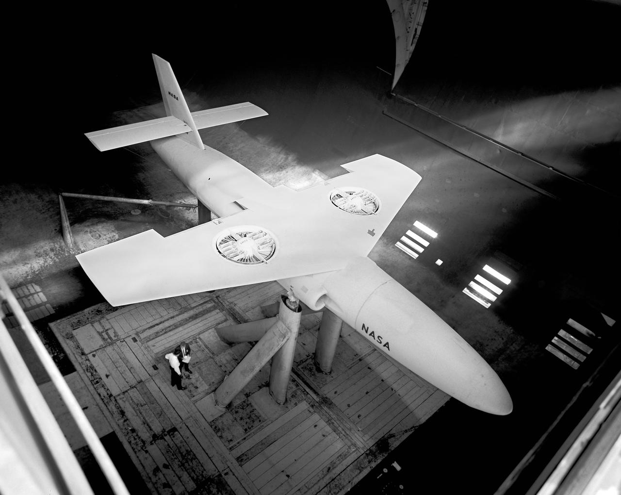
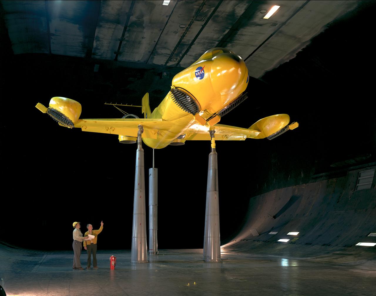
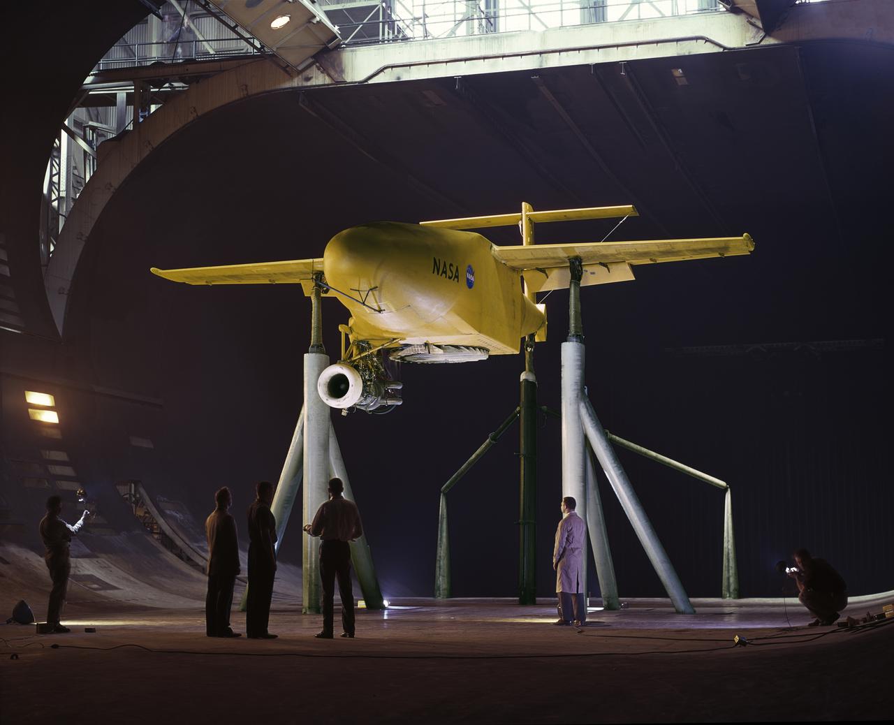
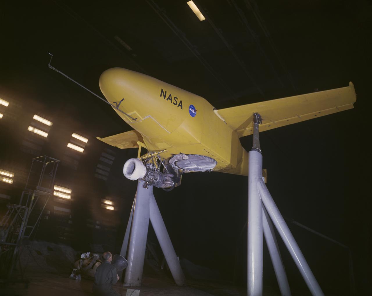
Forward overhead view of lift fan transport model, with two, of a possible six, high pressure ratio wing lift fans. Lift Fan Model In 40 X 80 Wind Tunnel; Test 40-347
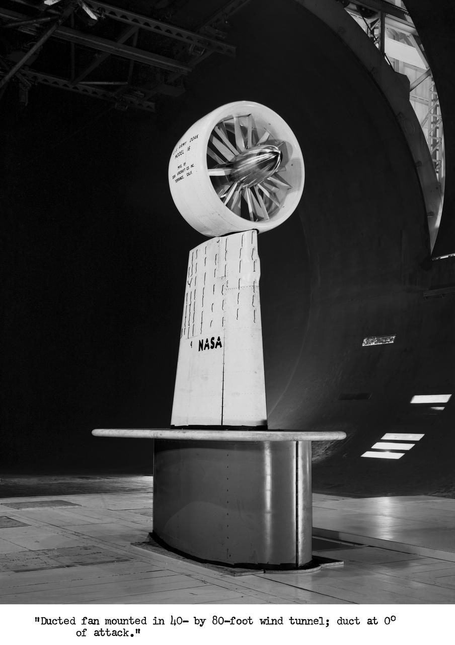
3/4 front view of Ducted fan model with 40 deg. exit vane cascade, semi span model.
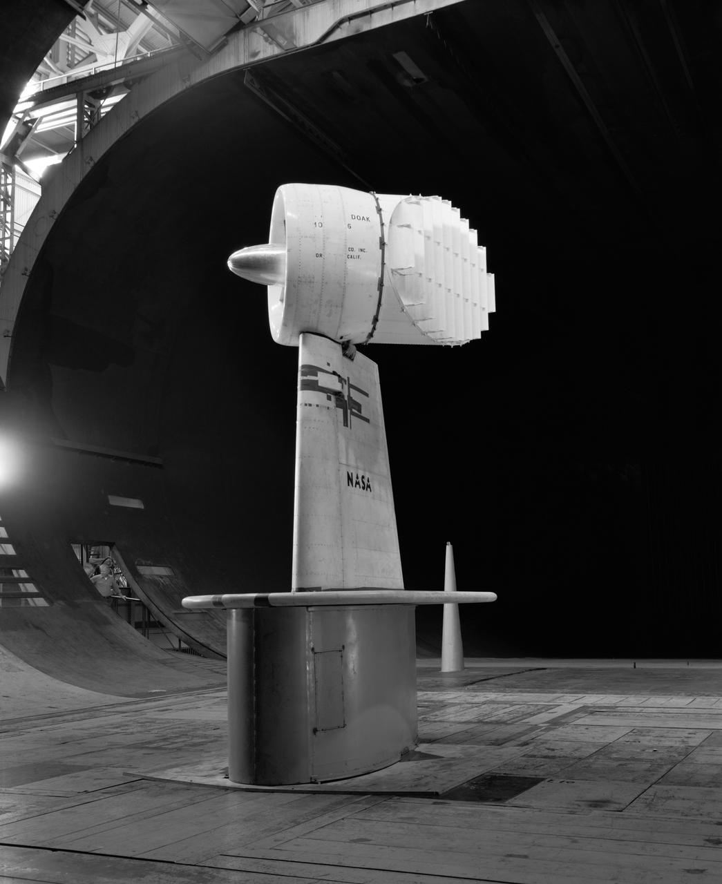
Wind Tunnel investigation of ducted fan though 180 deg angle of attack. 3/4 front view of Doak ducted fan, semi-span model with tufts.
G.E. Fan-in-fuselage model (lifting). 3/4 rear view of fan at low G.P. position. Lift fan on variable height strut for ground effects studies with reaction control. T-Tail.
G.E. Fan-in-fuselage model (lifting). 3/4 front view of fan at low G.P. position. Lift fan on variable height strut for ground effects studies. T-Tail
3/4 rear view of ducted fan model with cascade exit vane in Ames 40x80 foot wind tunnel, with Tom Seymore, mechanic for Ames.
Top view if GE fan model, 3/4 top view. Straight wing. 1 fan per wing, conventional struts. Woody Kook, Branch Chief.

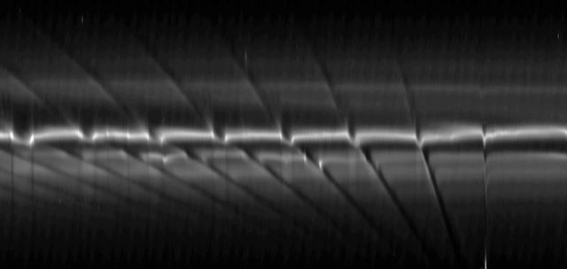
Bright Streaks and Dark Fans
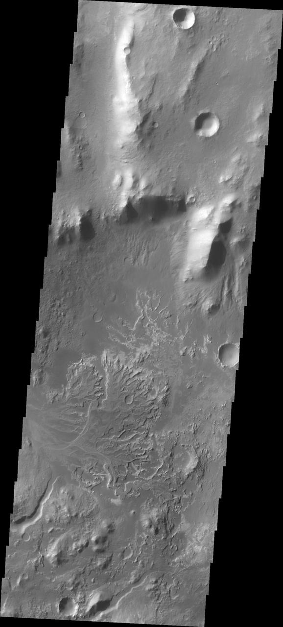
Alluvial Fans in Kasei Vallis
G.E fan-in-fuselage model (lifting) 3/4 front view of fan at low G.P. position
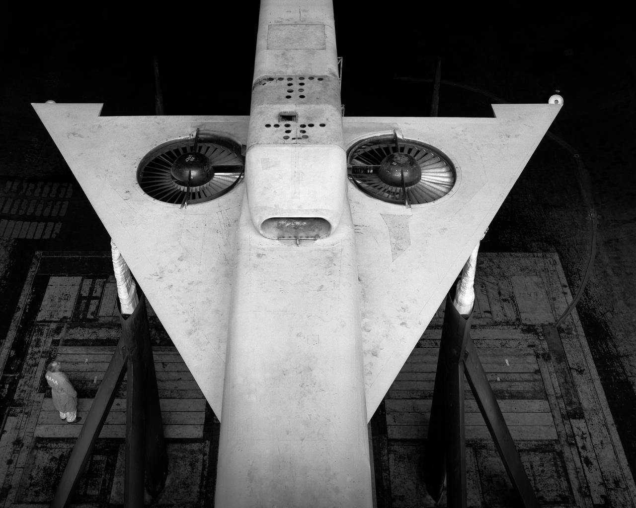
Top front view of Delta wing lift fan fighter model.
Tandem dual ducted fan mounted on ground plate. 3/4 rear view. Testing for recirculation decrease in performance of lift fans varies with ground effect.

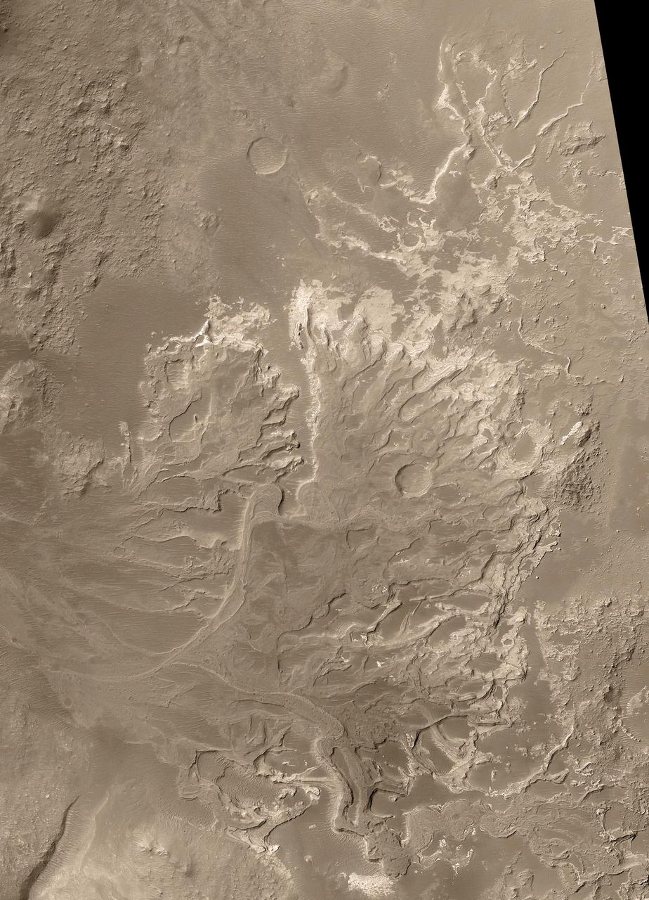
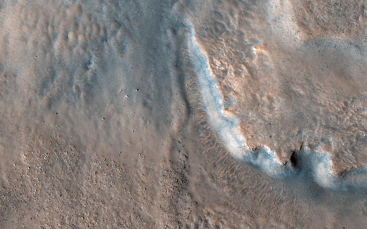
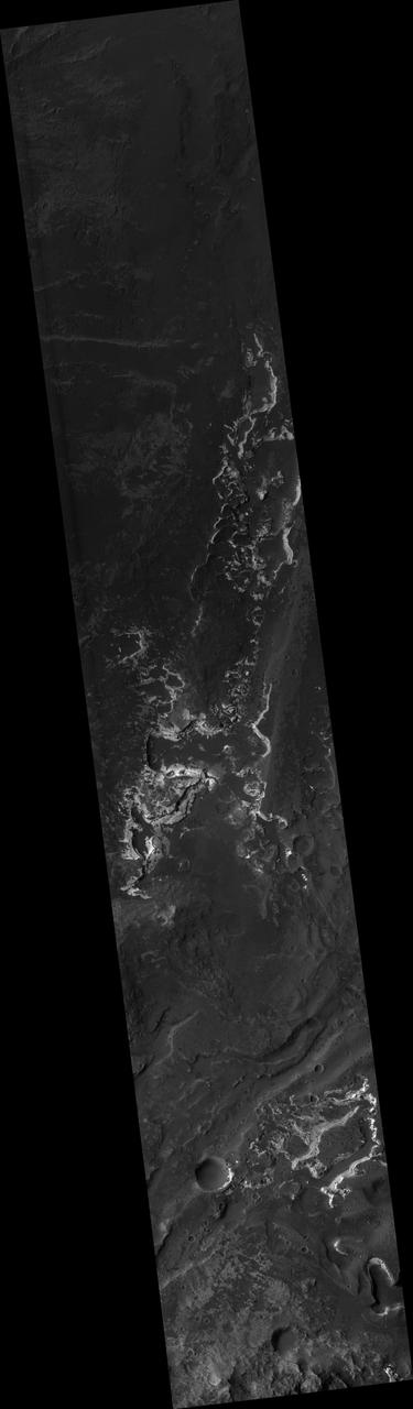
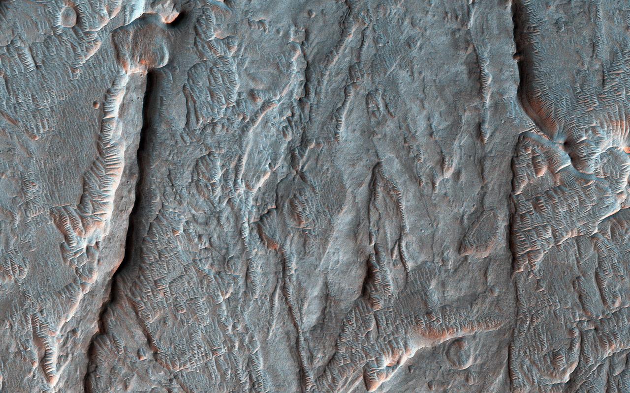
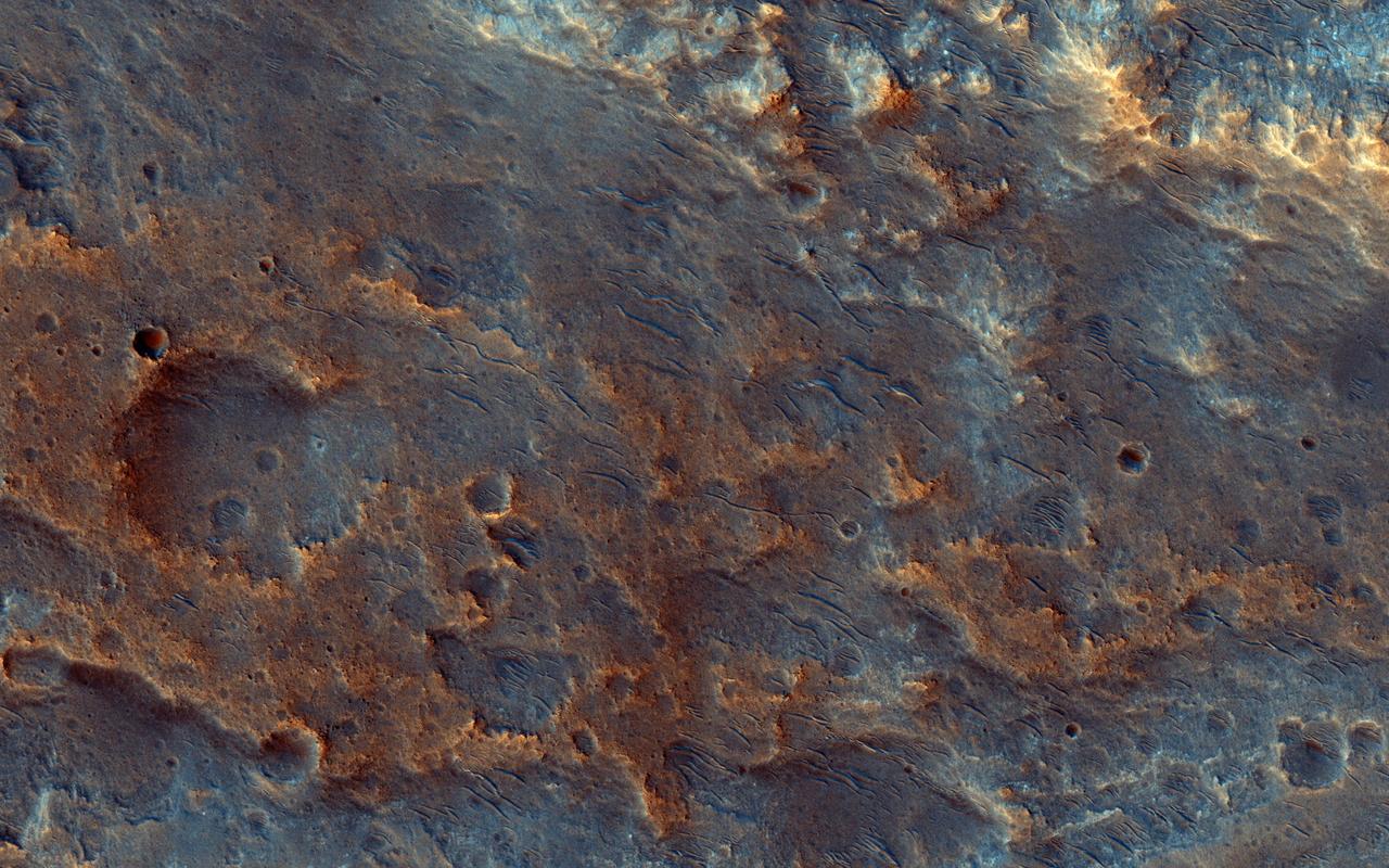
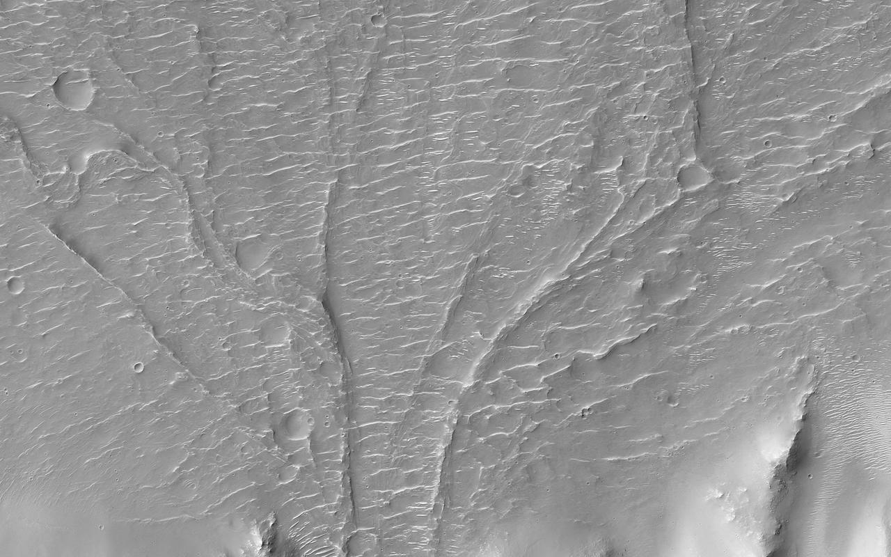
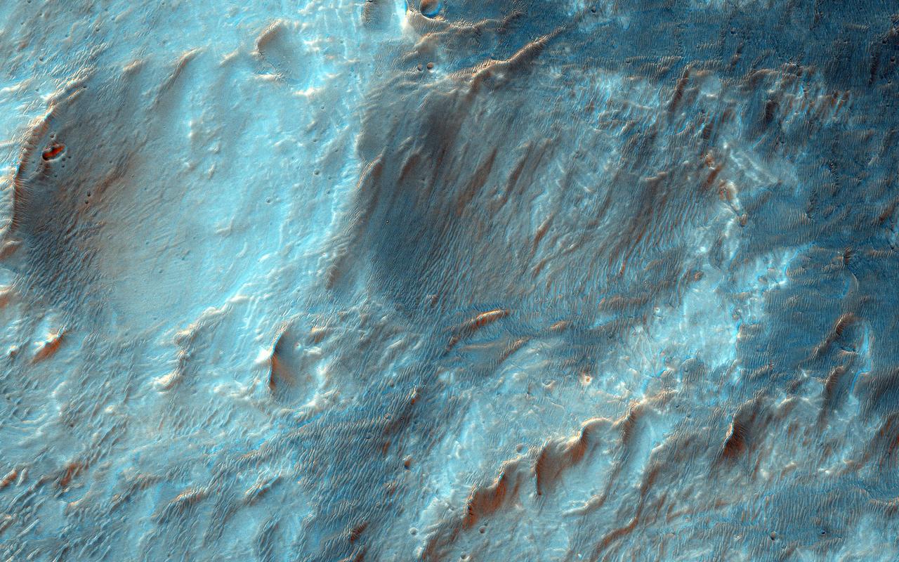
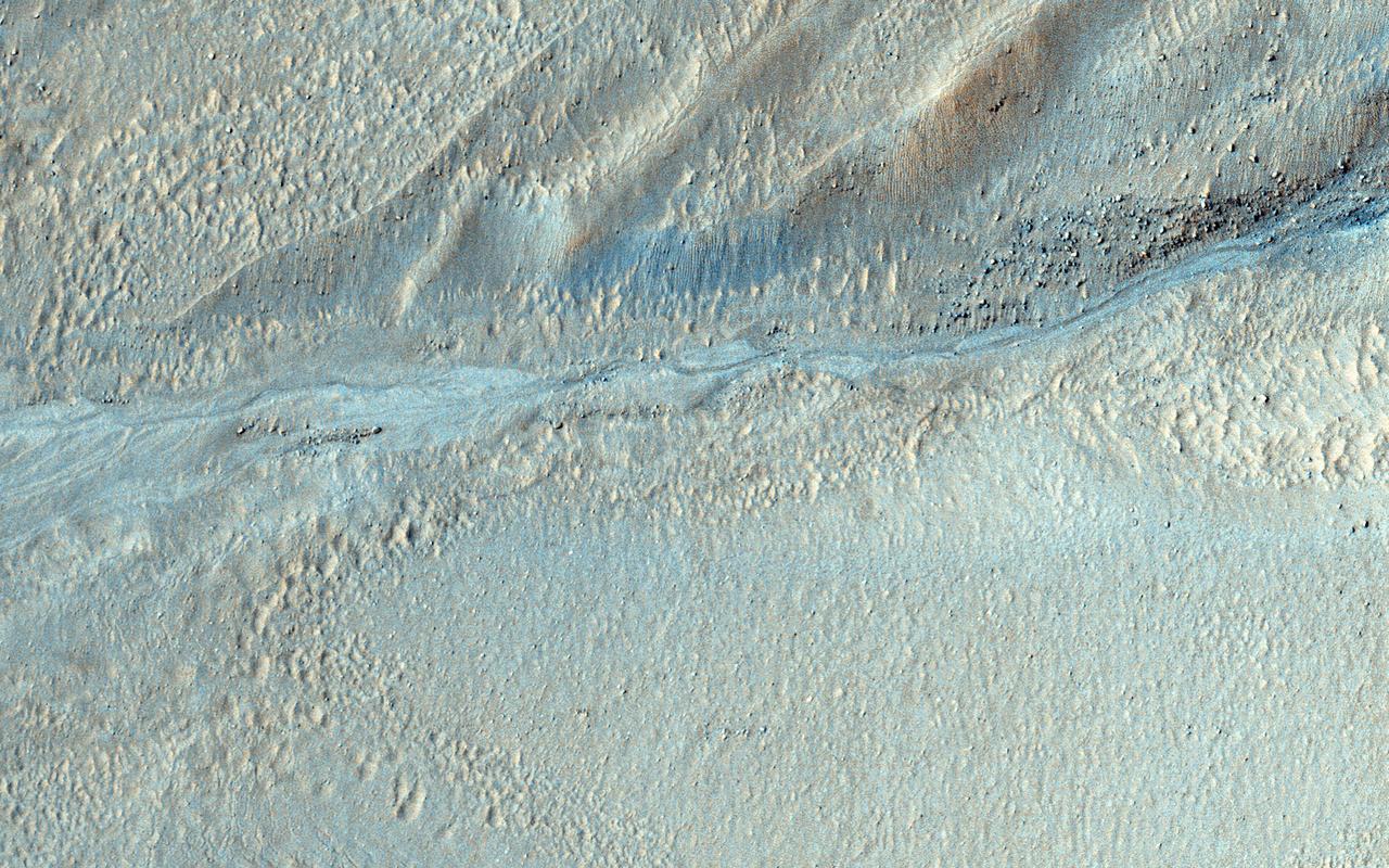
Shown in this image from NASA's Mars Reconnaissance Orbiter (MRO) are alluvial fans, fan-shaped deposits emerging from regions of steep topography. Alluvial fans on Mars are thought to be ancient and record past episodes of flowing water. This image shows part of one of those fans, which has been eroded. The old stream channels now stand above the rest of the fan as ridges, mostly in the southern (bottom) part of the image. This can occur because the channel materials are more resistant to erosion; perhaps they had larger grains (gravel) or because minerals deposited from the water cemented together. https://photojournal.jpl.nasa.gov/catalog/PIA22332
Distributory Fan Near Holden Crater
Alluvial Fan Along a Crater Wall
Bell X-22A full scale, Model-C ducted fan with semi-span mount. Duct at 90 degrees with Chuck Greco.
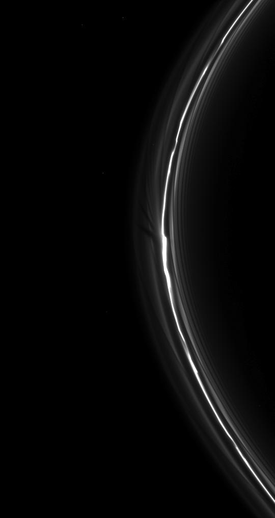
NASA Cassini spacecraft spies a fan in Saturn tenuous F ring. This fan-like structure appears as dark lines spreading outward from the left of the bright clump of ring material near the center of the image.
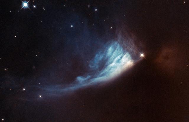
The Universe is rarely static, although the timescales involved can be very long. Since modern astronomical observations began we have been observing the birthplaces of new stars and planets, searching for and studying the subtle changes that help us to figure out what is happening within. The bright spot located at the edge of the bluish fan-shaped structure in this Hubble image is a young star called V* PV Cephei, or PV Cep. It is a favorite target for amateur astronomers because the fan-shaped nebulosity, known as GM 1-29 or Gyulbudaghian’s Nebula, changes over a timescale of months. The brightness of the star has also varied over time. Images of PV Cep taken in 1952 showed a nebulous streak, similar to a comet’s tail. However, this had vanished when new images of the star were obtained some twenty-five years later. Instead, the blue fan-shaped nebula had appeared. Twenty-five years is a very short period on cosmic timescales, so astronomers think that the mysterious streak may have been a temporary phenomenon, such as the remnants of a massive stellar flare — similar to the solar flares we are used to seeing in the solar system. At the same time as this was happening, the star itself was brightening. This provided the light to illuminate the newly formed fan-shaped nebula. This brightening might be related to the start of the hydrogen-burning phase of the star, which would mean that it was reaching maturity. PV Cep is thought to be surrounded by a disc of gas and dust, which would stop light from escaping in all directions. The fan-like appearance is therefore probably a result of starlight escaping from the dust disc and projecting onto the nebula. PV Cep is located in the northern constellation of Cepheus at a distance of over 1600 light-years from Earth. European Space Agency/NASA Hubble <b><a href="http://www.nasa.gov/audience/formedia/features/MP_Photo_Guidelines.html" rel="nofollow">NASA image use policy.</a></b> <b><a href="http://www.nasa.gov/centers/goddard/home/index.html" rel="nofollow">NASA Goddard Space Flight Center</a></b> enables NASA’s mission through four scientific endeavors: Earth Science, Heliophysics, Solar System Exploration, and Astrophysics. Goddard plays a leading role in NASA’s accomplishments by contributing compelling scientific knowledge to advance the Agency’s mission. <b>Follow us on <a href="http://twitter.com/NASA_GoddardPix" rel="nofollow">Twitter</a></b> <b>Like us on <a href="http://www.facebook.com/pages/Greenbelt-MD/NASA-Goddard/395013845897?ref=tsd" rel="nofollow">Facebook</a></b> <b>Find us on <a href="http://instagram.com/nasagoddard?vm=grid" rel="nofollow">Instagram</a></b>
3/4 lower front view of DC-9 lift/cruz fan transport model. Pictured with Eloy Martinez (left, mechanic) Leo Hall (right, engineer).
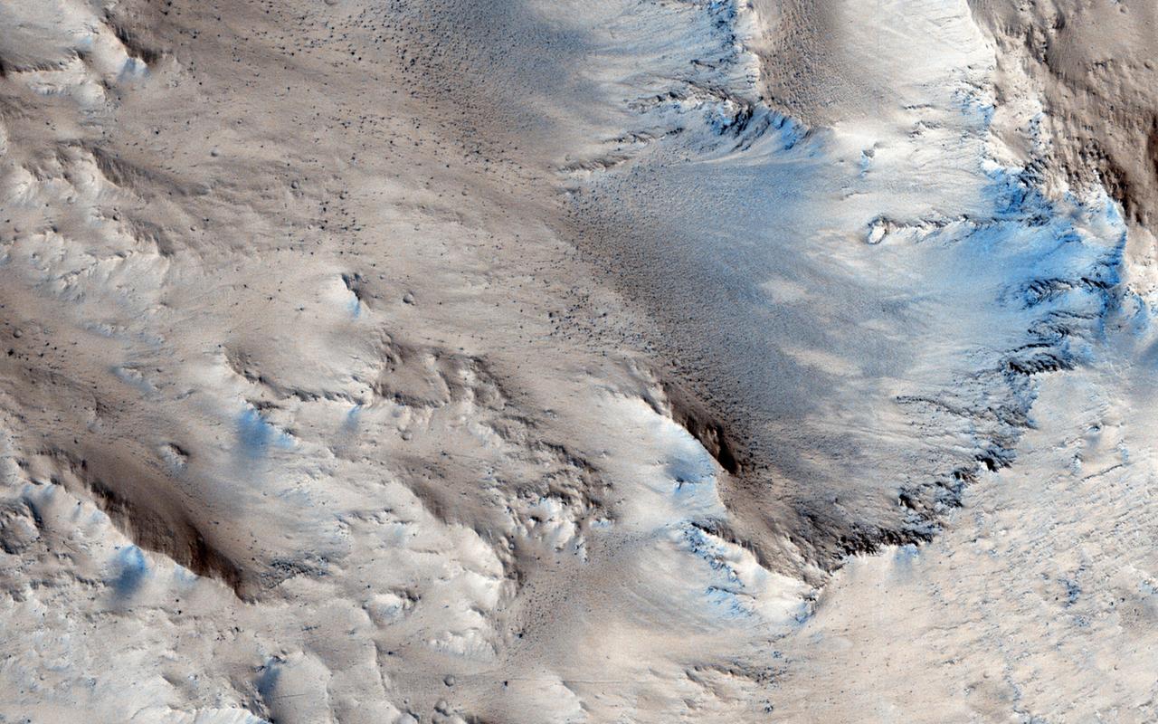
This image acquired by NASA's Mars Reconnaissance Orbiter on April 29, 2018, shows an impact crater approximately 23 kilometers across is home to fan-shaped deposits that extend from the rim and sit on the interior crater floor. Thick beds with varying tone are exposed along the edge of the fan. Shallow valleys that carve into the smooth upland surfaces outside of the crater may provide clues regarding the formation of the deposits. Many boulder-sized blocks sit on the interior crater floor beyond the toe (distal edge) of the deposits. This fan-hosting crater is located near the boundary between Tempe Terra and Acidalia Planitia in the Northern Hemisphere of Mars. More information is available at https://photojournal.jpl.nasa.gov/catalog/PIA22592
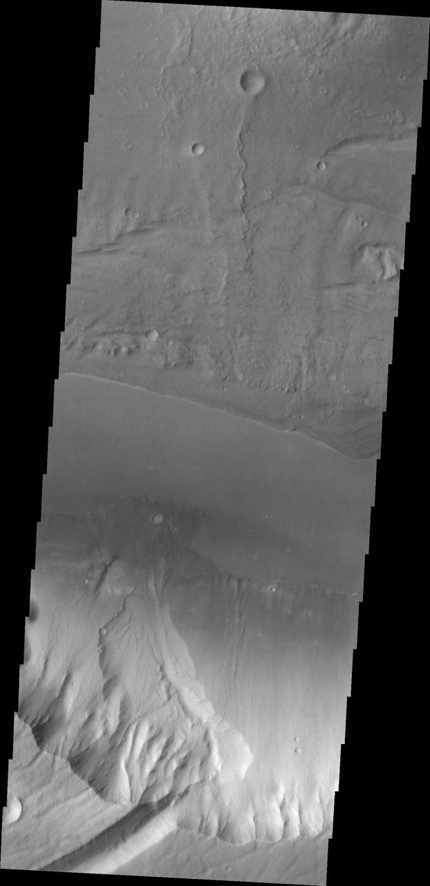
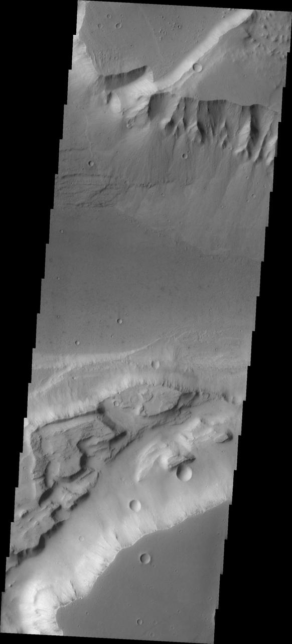
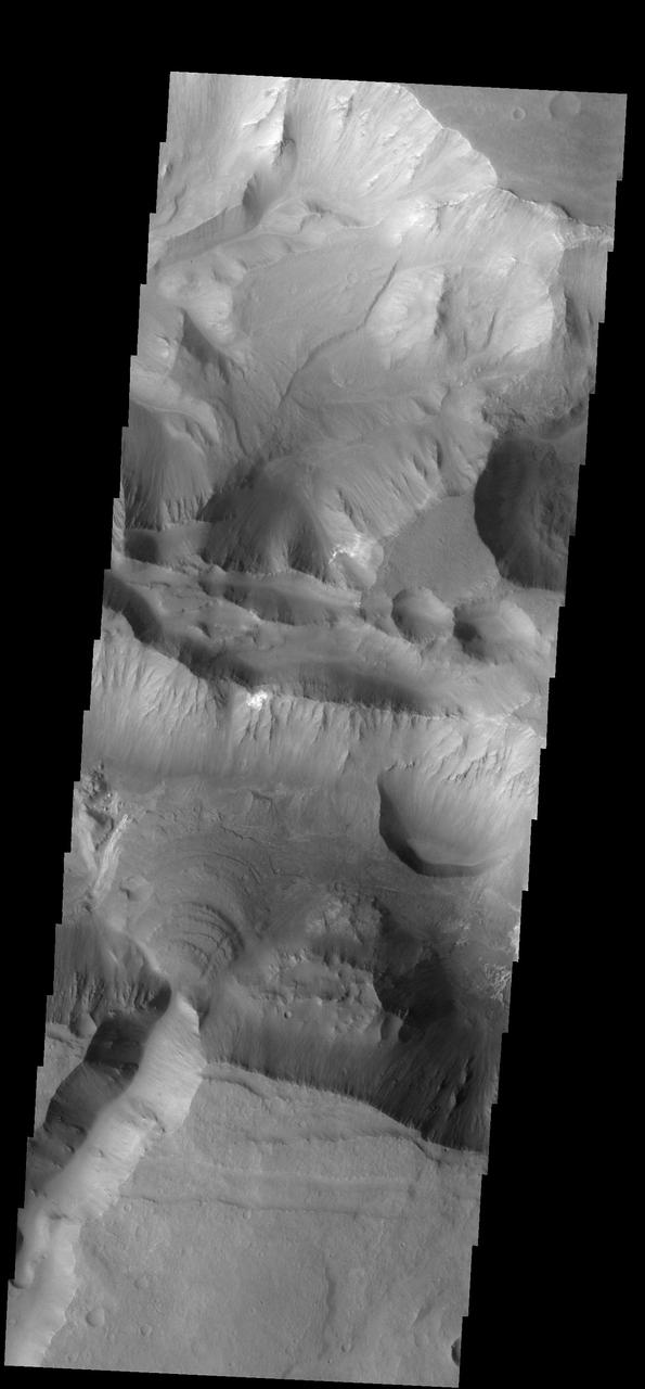
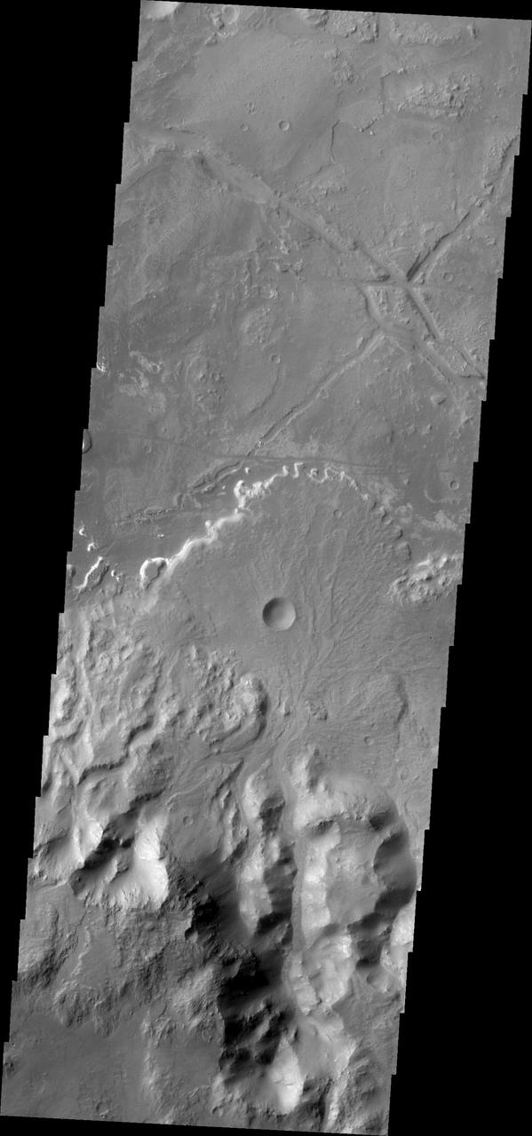
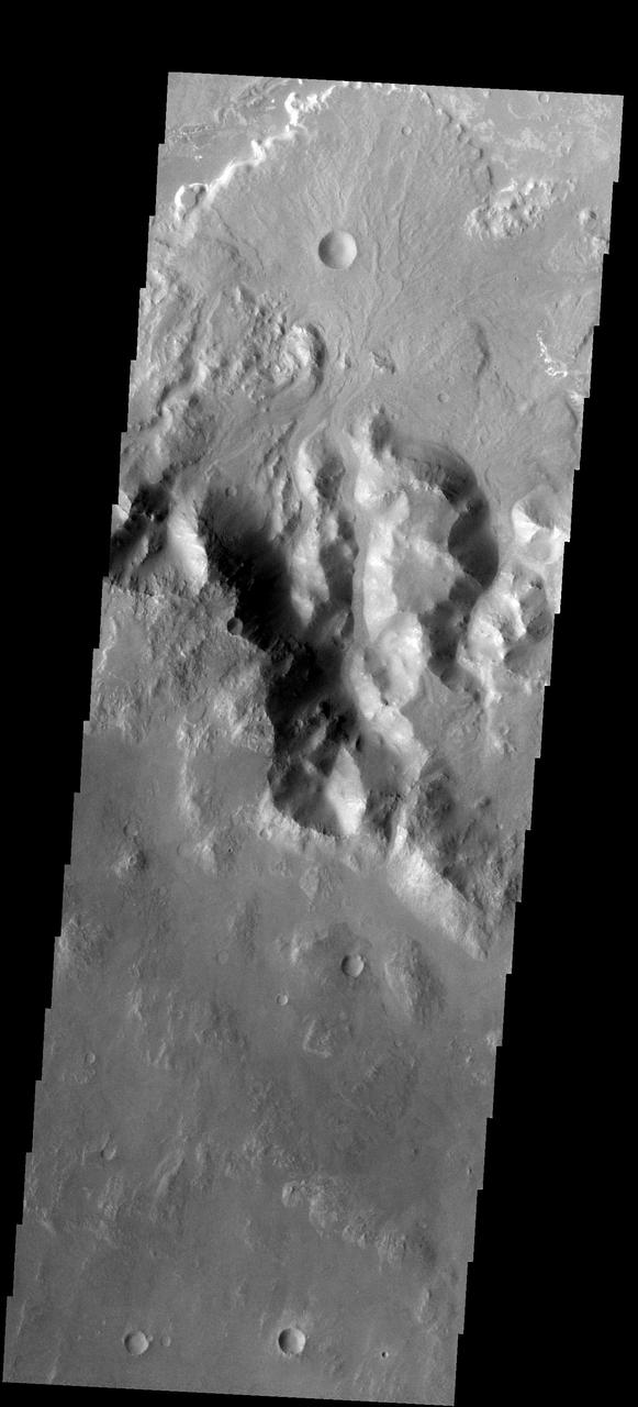
At the base of this slope is a fan-shaped deposit of the slope forming material. The channel that the fan rests upon is Kasei Valles in this image as seen by NASA 2001 Mars Odyssey spacecraft.
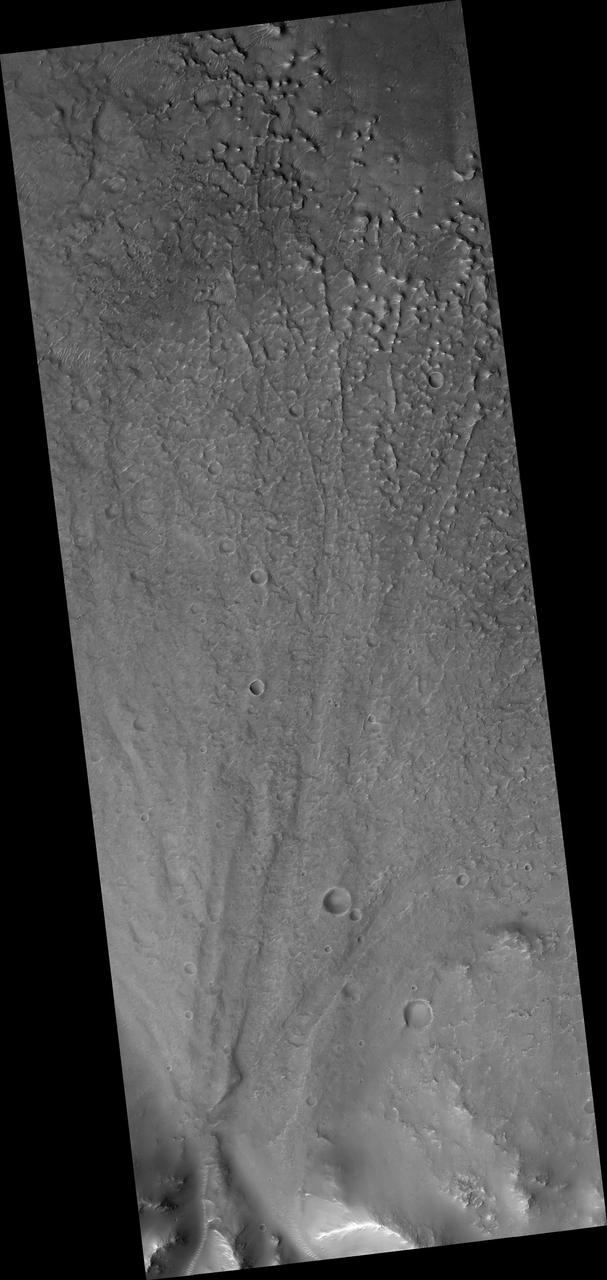
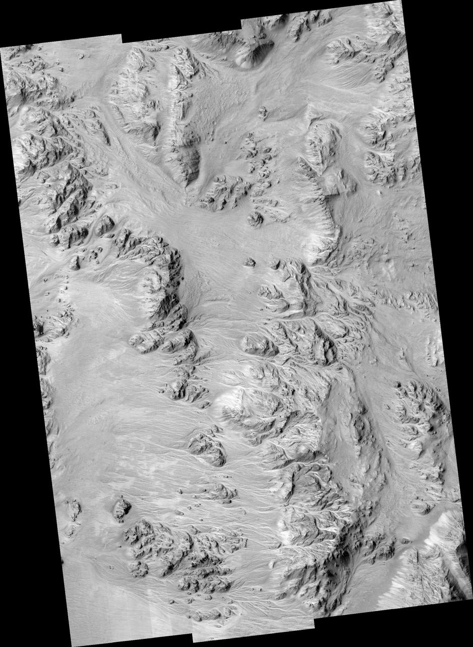
This image from NASA Mars Reconnaissance Orbiter shows a landscape that is pervasively eroded, right up to the tops of the ridges, with channels extending down into depositional fans much like alluvial fans in the Mojave Desert.
Triangular shaped deposits at cliff edges are termed alluvial fans. Alluvial fans typically form in arid regions were water flow is limited, so deposits of material are not washed away as seen by NASA 2001 Mars Odyssey spacecraft.
This beautiful fan deposit is located at the end of a mega-gully that empties into the southern trough of Coprates Chasma

The alluvial fans on the north side of this channel possibly represent the most recent activity in Kasei Valles
Alluvial Fans in Mojave Crater: Did It Rain on Mars?
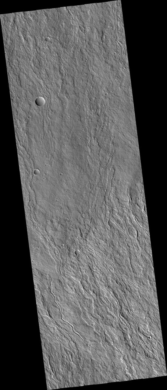
Fans of Lava Flows on the Flanks of Olympus Mons
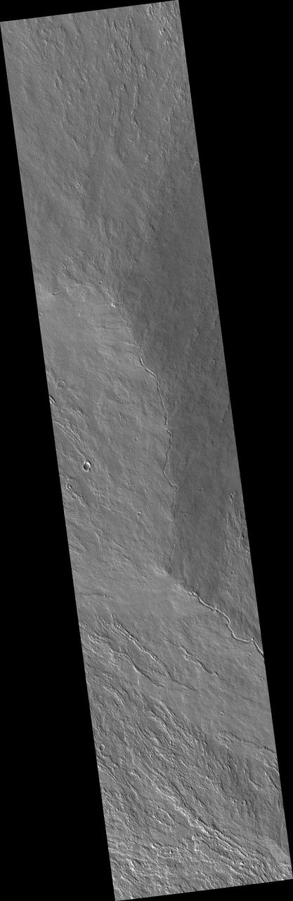
Large Lava Fan on the Northwestern Flank of Olympus Mons
Dust Fans on the Seasonal Carbon Dioxide Polar Cap
Active Processes: Bright Streaks and Dark Fans
Proposed MSL site in Holden Crater Fan
Alluvial fans are gently-sloping wedges of sediments deposited by flowing water. Some of the best-preserved alluvial fans on Mars are in Saheki Crater, seen here by NASA Mars Reconnaissance Orbiter spacecraft.
This image was acquired on May 30, 2018 by NASA's Mars Reconnaissance Orbiter. This image shows inverted channels within a fan whose origin could be either fluvial (produced by the action of a stream) or alluvial (created by sedimentary deposits). If the fan is alluvial, then it formed on dry land. If the fan is fluvial, then it could have formed in water, like a delta. Similar fans with inverted channels are found in Eberswalde and Jezero craters, both of which are interpreted as deltas and are considered candidate locations of future rover landing sites. More information is available at https://photojournal.jpl.nasa.gov/catalog/PIA22683
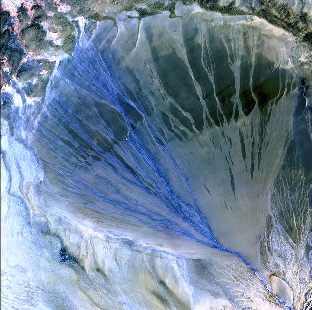
Image taken 5/2/2002 by ASTER: A vast alluvial fan blossoms across the desolate landscape between the Kunlun and Altun mountain ranges that form the southern border of the Taklimakan Desert in China's XinJiang Province. This image can be found on ASTER Path 143 Row 34, center: 37.43 N, 84.30 E. To learn more about the Landsat satellite go to: <a href="http://landsat.gsfc.nasa.gov/" rel="nofollow">landsat.gsfc.nasa.gov/</a>
Taken by NASA 2001 Mars Odyssey spacecraft, this image shows a fan shaped deposit located on the floor of Holden Crater.
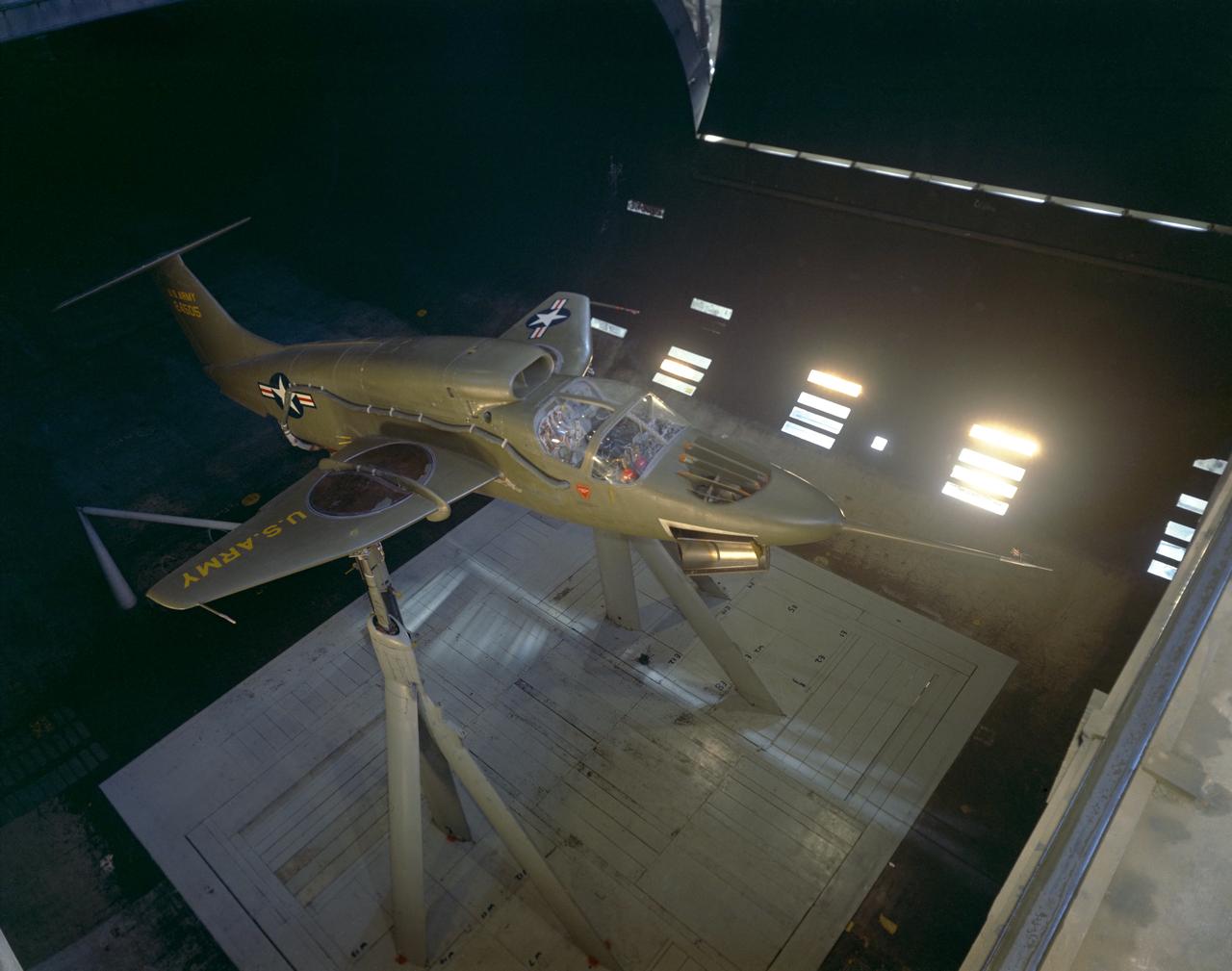
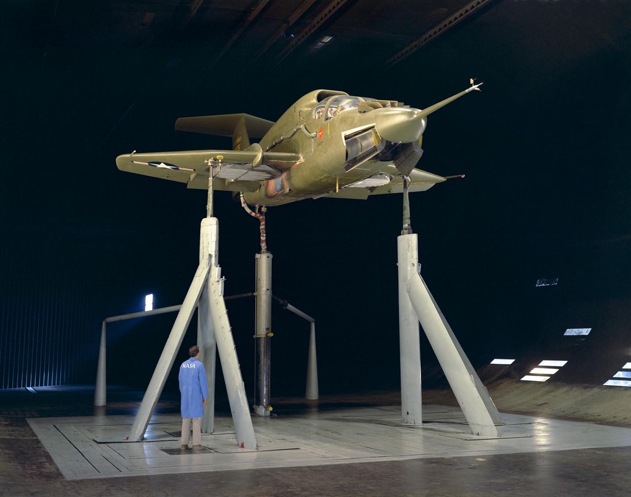
3/4 front view VZ-11 ground test - variable height struts. Engines of the VZ-11 are a pair of General Electric J85-5 turbojets, mounted in high in the centre fuselage, well away from fan disturbance. Designed in the Ames 40x80 foot wind tunnel.
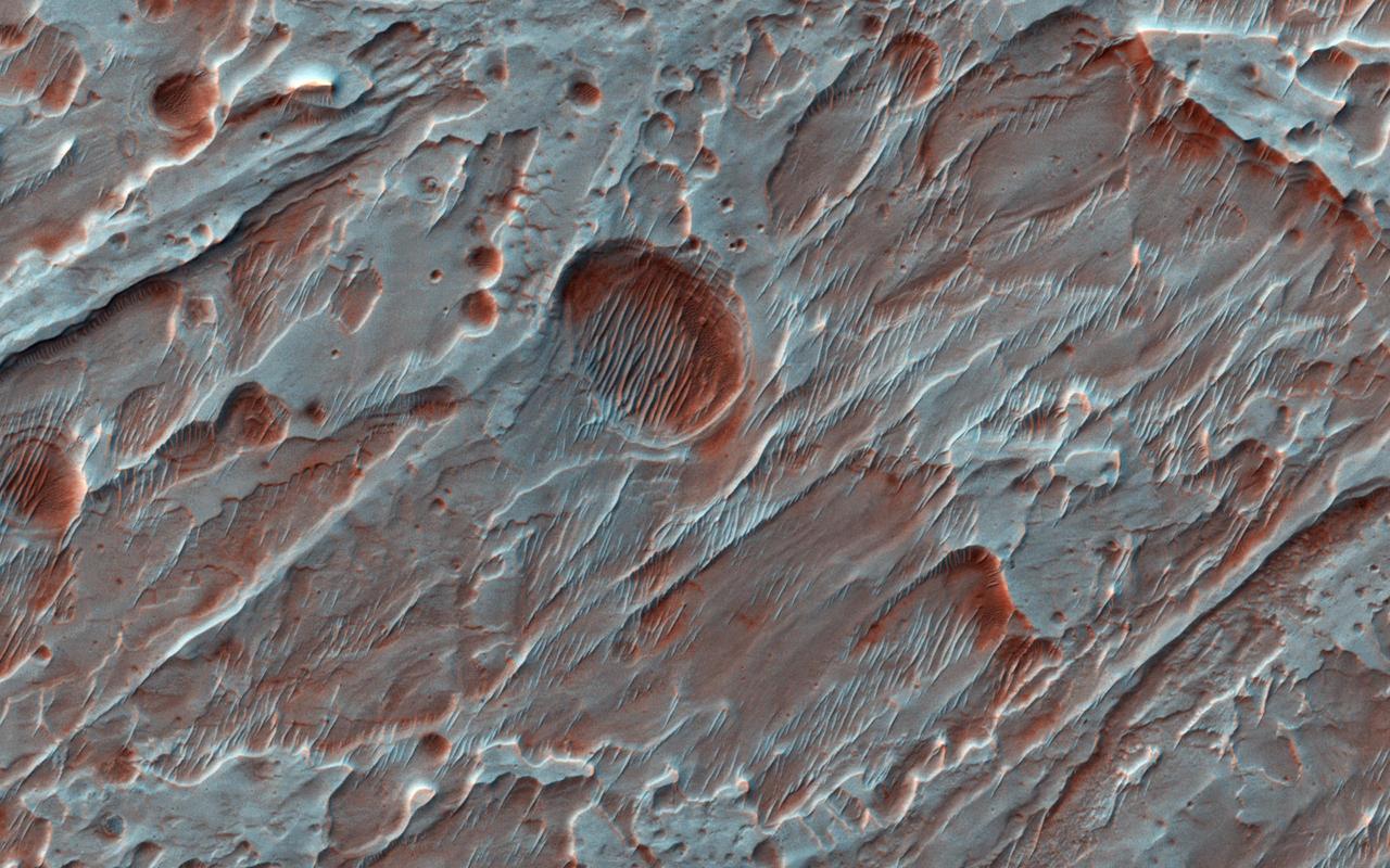
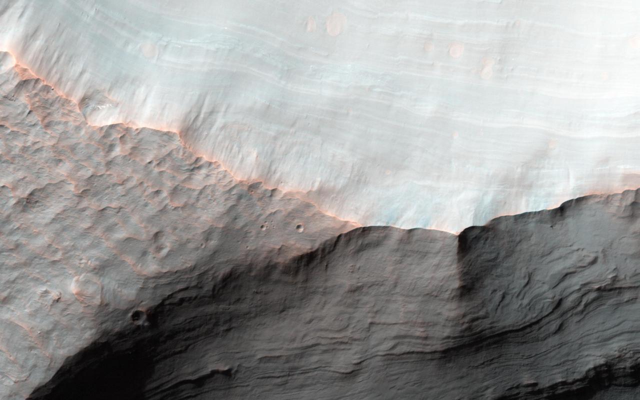
This image, acquired by NASA's Mars Reconnaissance Orbiter on Sept. 16, 2013, shows Roddy Crater on Mars, home to several large alluvial fans, which formed as water moved sediment from the mountainous crater rim and deposited it onto the flatter crater floor. Alluvial fans are found on Earth, Mars, and even Saturn's moon, Titan. The fans built up over time during intense rain storms or from melting snow. Due to the strong winds on Mars, the river channels that once carried water and sediment on the fan surfaces are now standing as raised ridges and platforms. A thin blanket of ejecta (upper right) from a small crater on Roddy's eastern rim protected underlying fan surfaces from modification by the wind compared to nearby, unprotected fans (left). The scarp beneath the thin ejecta surface exposes beautiful light-toned layers from the alluvial fans below. More information is available at https://photojournal.jpl.nasa.gov/catalog/PIA22594
In this observation, does the morphology of these possible sedimentary fans match those found in Mojave Crater not picture here?
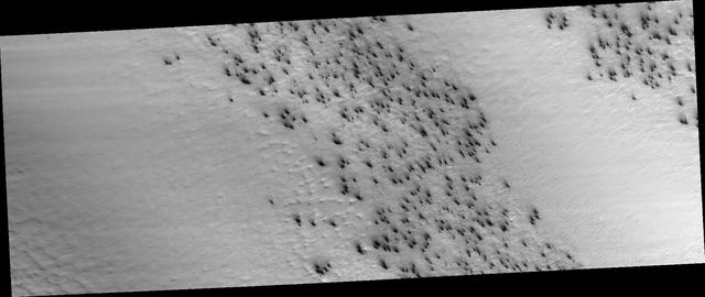
Every Martian spring, fans of dust are blown out from under the seasonal layer of carbon dioxide ice that forms a polar cap over the winter. Gas blowing out from under the ice carries with it a load of dust that is deposited on the surface in a direction determined by the wind at the time of the eruption. Like windsocks, these fans in a polar area we've dubbed Macclesfield, record the direction that the wind was blowing. A citizen science task at Planet Four enlists the public to outline the fans. Their measurements go into a data base that will ultimately help us to understand weather on Mars. https://photojournal.jpl.nasa.gov/catalog/PIA23954
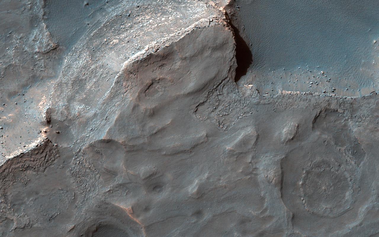
Gale Crater is well-known as the landing site of NASA's Curiosity rover, which has explored the northwest crater floor since 2012. But the entire crater is full of fascinating geology, some beyond the rover's reach. This image covers a fan of sedimentary rock on the southeast crater floor. Ridges on the fan surface may be composed of coarse-grained sediment deposited in ancient streams. More recent wind erosion of the surrounding finer sediments could have left these channel deposits elevated in "inverted relief." A closeup shows some of these ridges, as well as light-toned layers of sediment exposed along the fan edge. The fan is also punctured by scattered circular impact craters. One of these craters appears to have a circular deposit of sedimentary rock filling its floor, suggesting that it formed during the span of time that streams were active here. Features like this help scientists to infer the geologic history of the region. https://photojournal.jpl.nasa.gov/catalog/PIA25988
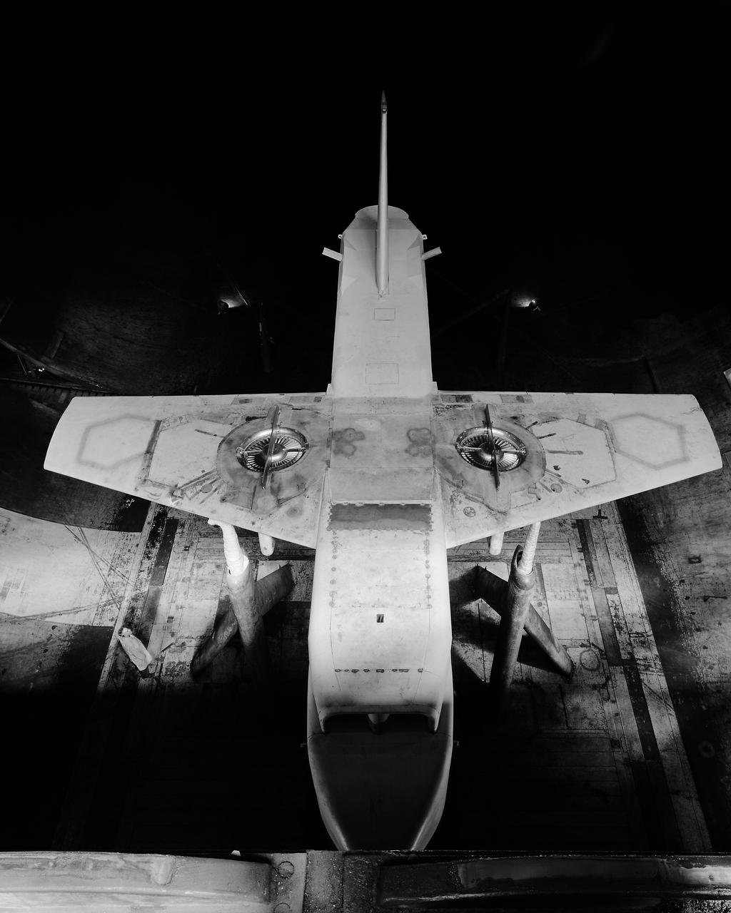
Overhead view of Ryan XV-5A lift-fan VSTOL airplane.
The focus of this image from NASA Mars Reconnaissance Orbiter is on the western end of a fan-shaped landform, located at the end point of a sinuous valley. Our observation covers crater-retaining mesas which overlie light-toned materials, both potentially related to the formation of the fan. There are also craters younger than the fan which impacted into these materials. http://photojournal.jpl.nasa.gov/catalog/PIA19845

This image is from a set of mosaic images from NASA Cassini spacecraft showing three fan-like structures in Saturn tenuous F ring. Such fans suggest the existence of additional objects in the F ring.
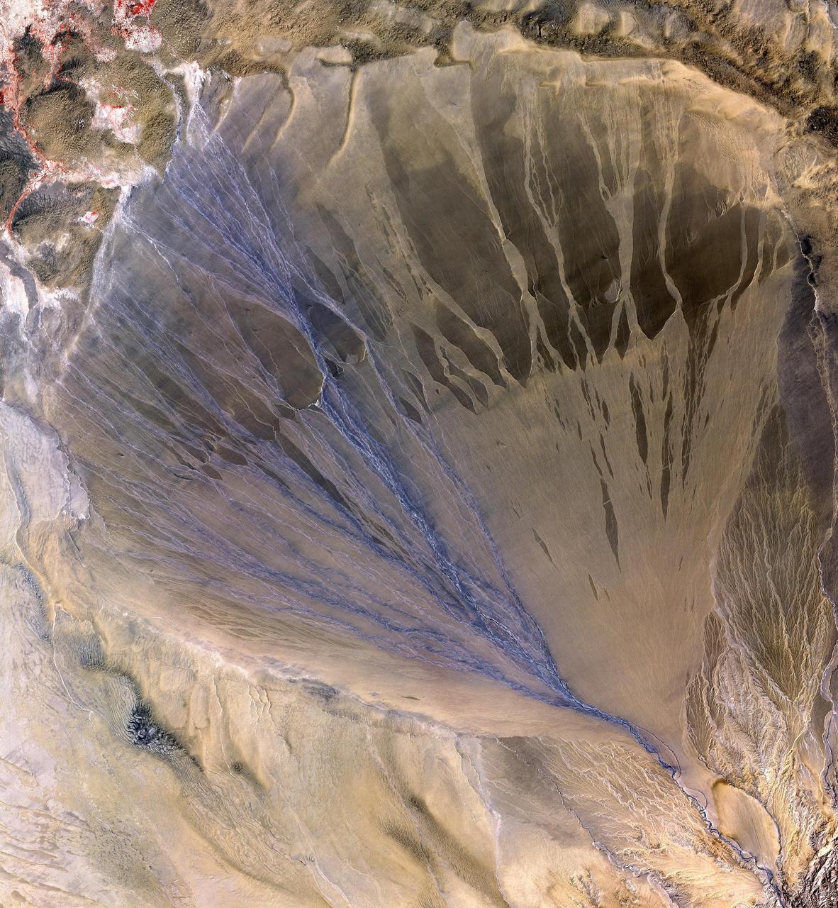
NASA Terra spacecraft shows vast alluvial fan blossoms across the desolate landscape between two mountain ranges that form the southern border of the Taklimakan Desert in China XinJiang Province.
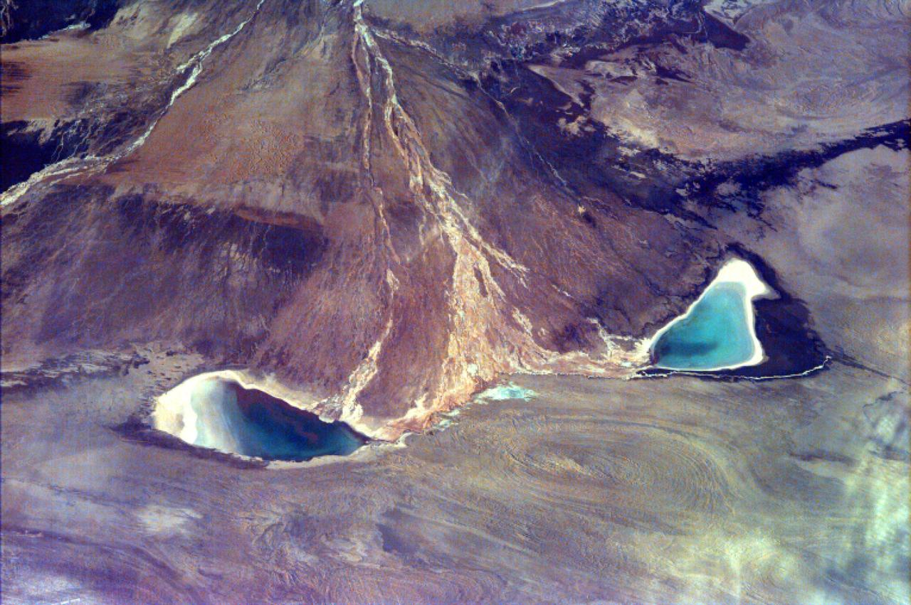
This image captures the beauty of a major alluvial fan in Tsinghai, a province located in Northwestern China. This archival image was taken from NASA Space Shuttle in 1997 as part of its ISS EarthKAM mission.

As winter turns to spring at the south polar ice cap of Mars, the rising sun reveals dark spots and fans emerging from the cold polar night. Using visual images left and temperature data right
This mosaic of images from NASA Cassini spacecraft depicts fan-like structures in Saturn tenuous F ring. Bright features are also visible near the core of the ring. Such features suggest the existence of additional objects in the F ring.
3/4 front view with cascade exit vane in Ames 40x80 foot wind tunnel, with Tom Seymore, mechanic for Ames.

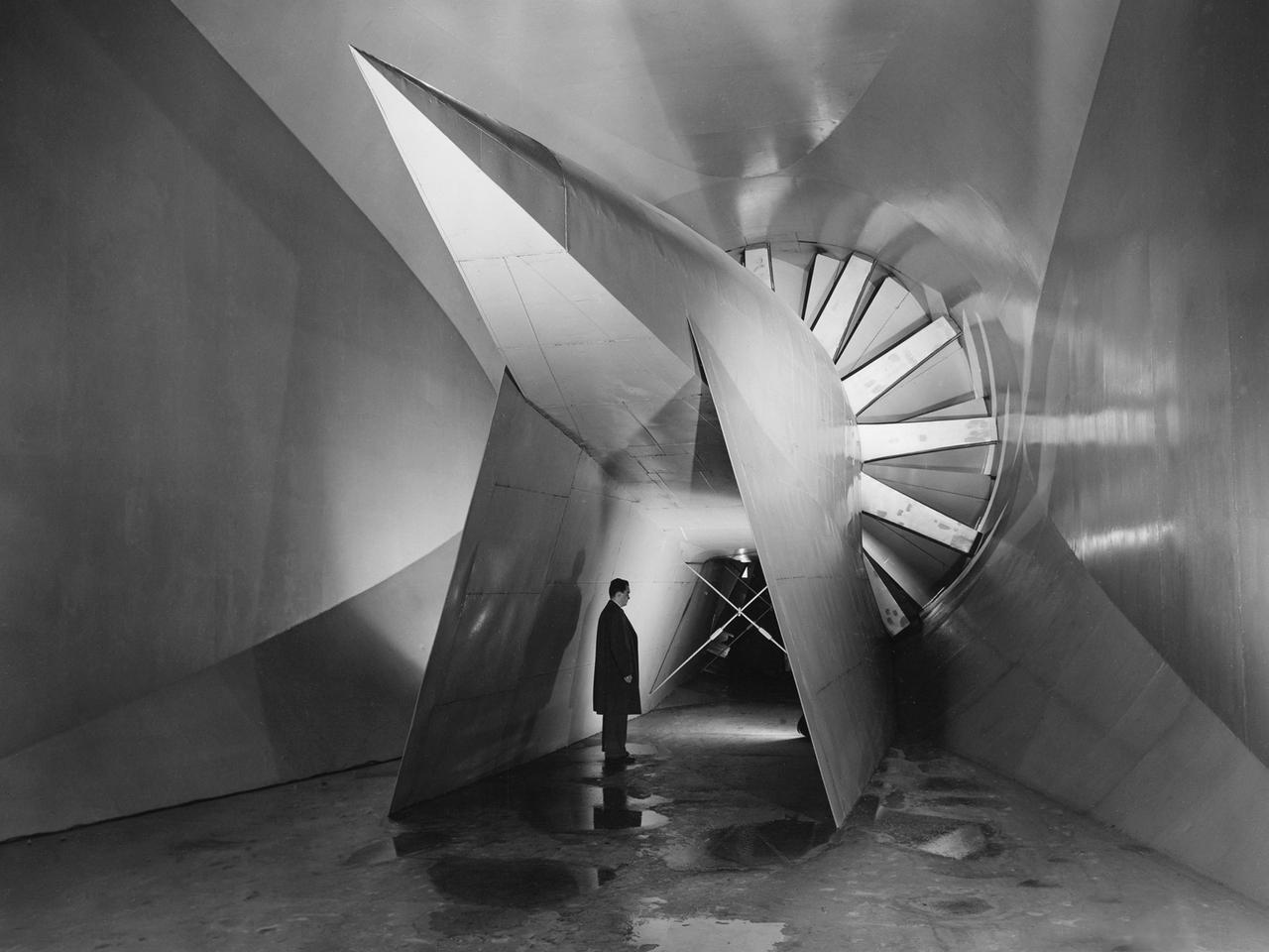
Concrete frame enclosing the fan drive bents of the 40x80 foot wind tunnel at ames. Once installed, six 40-foot-diameter fans, each powered by a 6000-horsepower electric motor maintained airflow at 230 mph or less (these are still tornado velocities).
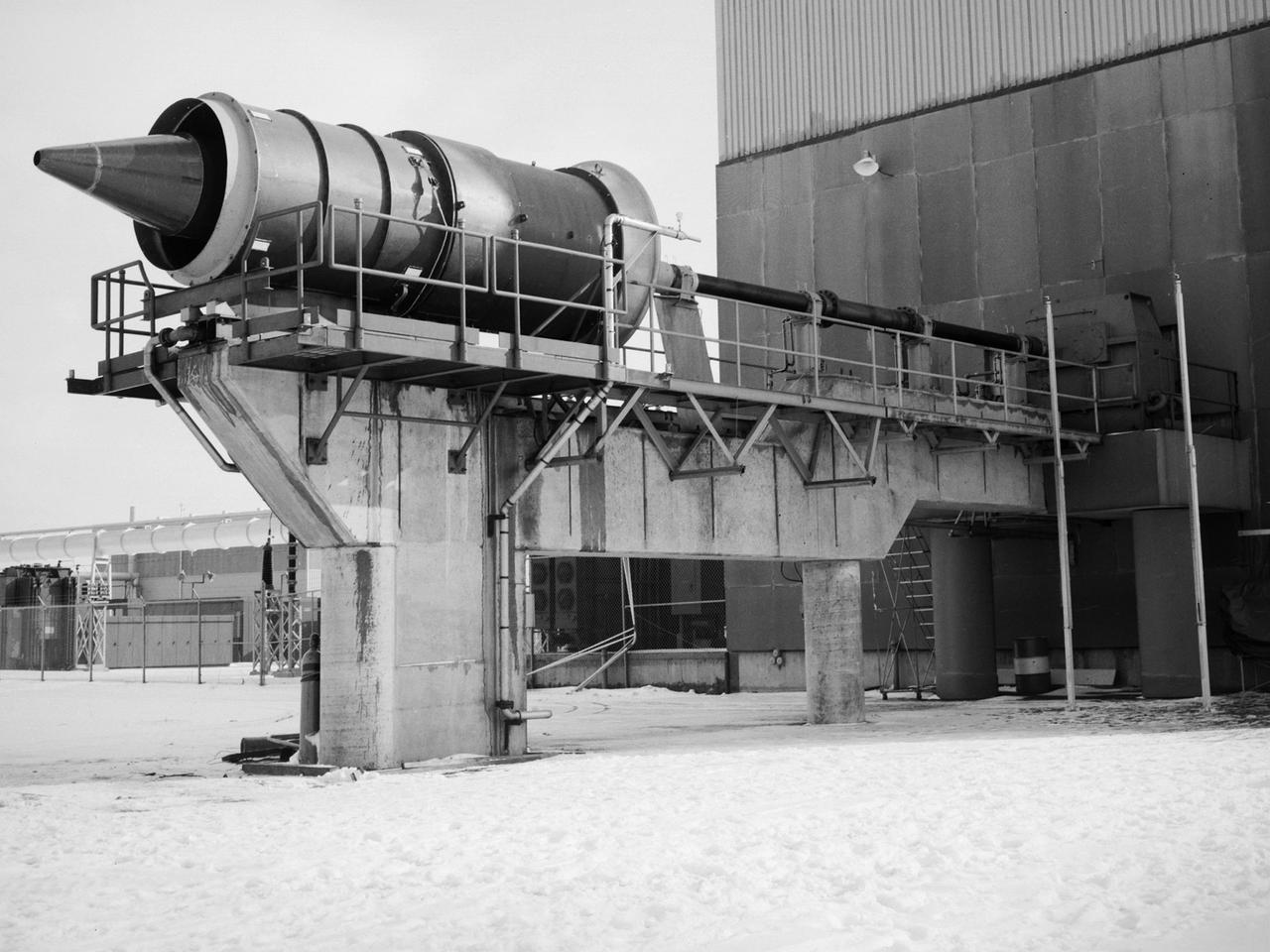
The Fan Noise Test Facility built at the Lewis Research Center to obtain far-field noise data for the National Aeronautics and Space Administration (NASA) and General Electric Quiet Engine Program. The engine incorporated existing noise reduction methods into an engine of similar power to those that propelled the Boeing 707 or McDonnell-Douglas DC-8 airliner. The new the low-bypass ratio turbofan engines of the 1960s were inherently quieter than their turbojet counterparts, researchers had a better grasp of the noise generation problem, and new acoustic technologies had emerged. Lewis contracted General Electric in 1969 to build and aerodynamically test three experimental engines with 72-inch diameter fans. The engines were then brought to Lewis and tested with an acoustically treated nacelle. This Fan Noise Test Facility was built off of the 10- by 10-Foot Supersonic Wind Tunnel’s Main Compressor and Drive Building. Lewis researchers were able to isolate the fan’s noise during these initial tests by removing the core of the engine. The Lewis test rig drove engines to takeoff tip speeds of 1160 feet per second. The facility was later used to test a series of full-scale model fans and fan noise suppressors to be used with the quiet engine. NASA researchers predicted low-speed single-stage fans without inlet guide vanes and with large spacing between rotors and stators would be quieter. General Electric modified a TF39 turbofan engine by removing the the outer protion of the fan and spacing the blade rows of the inner portion. The tests revealed that the untreated version of the engine generated less noise than was anticipated, and the acoustically treated nacelle substantially reduced engine noise.
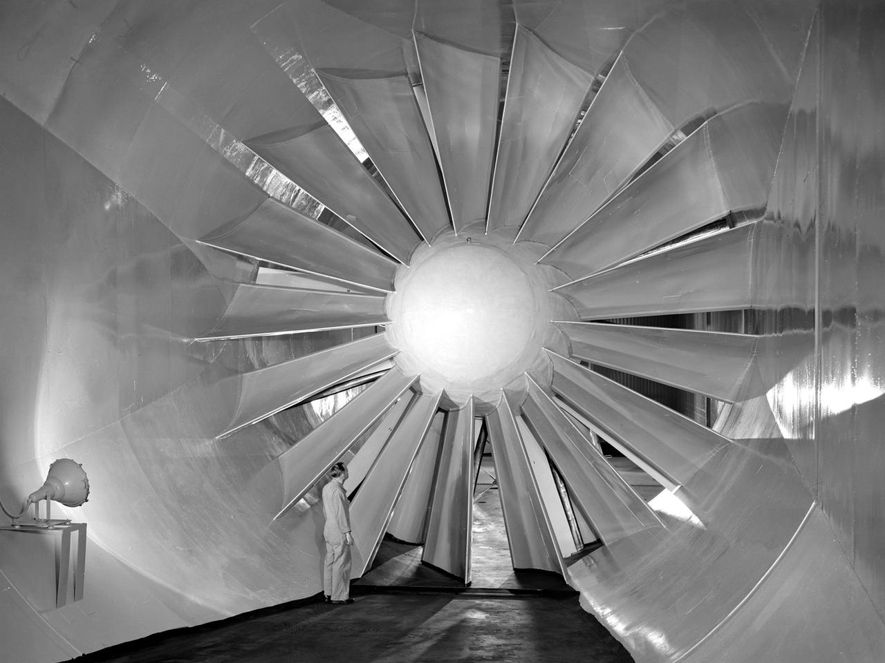
View of the drive fan for the Icing Research Tunnel at the National Advisory Committee for Aeronautics (NACA) Aircraft Engine Research Laboratory in Cleveland, Ohio. The tunnel was built in the early 1940s to study the formation of ice on aircraft surfaces and methods of preventing or eradicating that ice. Ice buildup adds extra weight, effects aerodynamics, and sometimes blocks airflow through engines. The original 4100-horsepower induction motor was coupled directly to the 24-foot-diameter fan. The 12 wooden fan blades were protected on their leading edge by a neoprene boot. The system could create air speeds up to 300 miles per hour through the tunnel’s 6- by 9-foot test section. The large tail faring extending from the center of the fan is used to guide the airflow down the tunnel in a uniform way. A new 5000-horsepower motor was installed in 1987, and the original fan blades were replaced in 1993.
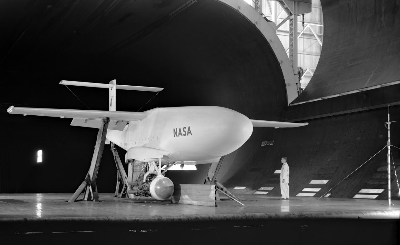
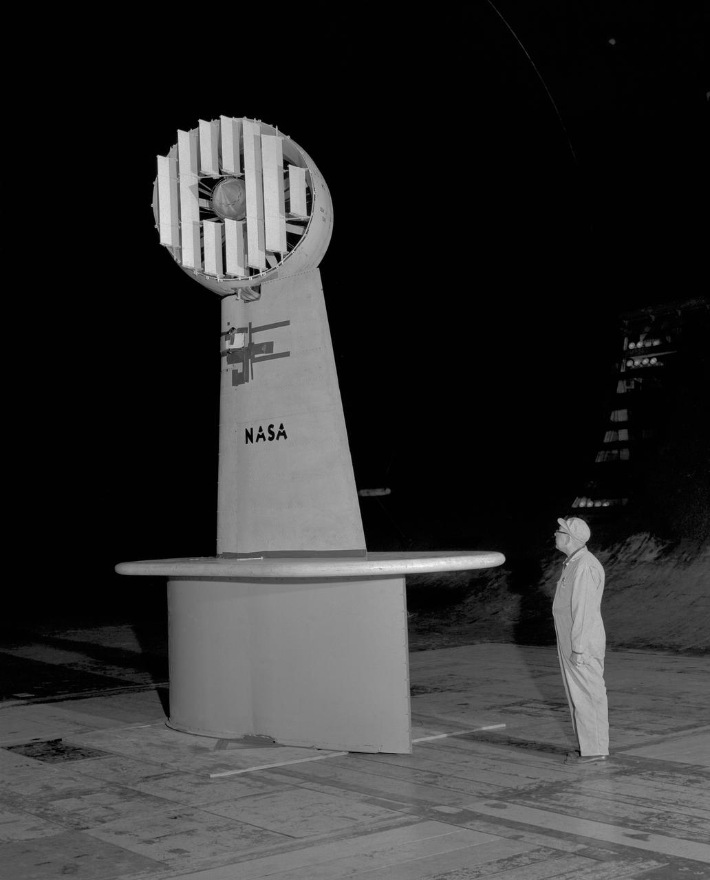
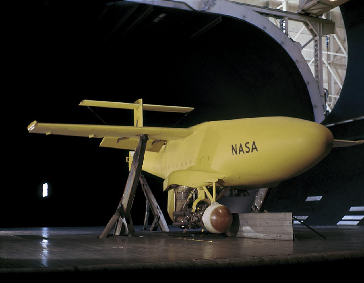
3/4 Low front view of fuselage and fan. Showing jet engine hanging below. Lift fan powered by jet exhaust. General Aerodynamic Characteristics of a Research Model with High Disk Loading Direct Lifting Fan Mounted in Fuselage
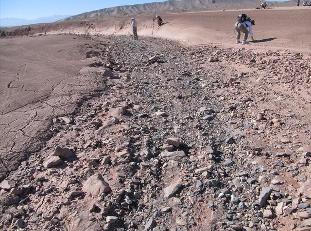
This image shows a dry streambed on an alluvial fan in the Atacama Desert, Chile, revealing the typical patchy, heterogeneous mixture of grain sizes deposited together.
3/4 Low front view of fuselage and fan. Showing jet engine hanging below. Lift fan powered by jet exhaust.
On Mars, alluvial fans are sometimes visible in impact crater basins, as material from the steep rims is transported radially inward to the relatively flat floor. This image is from NASA Mars Reconnaissance Orbiter.
3/4 front view from below, showing Pods and Fan Rotating. March A. Zeiger standing in front. Tandem Dual Ducted Fan V/STOL Model in Ames 40x80 foot Wind Tunnel
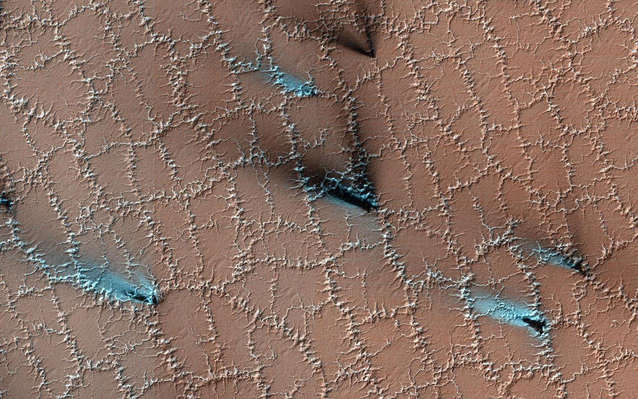
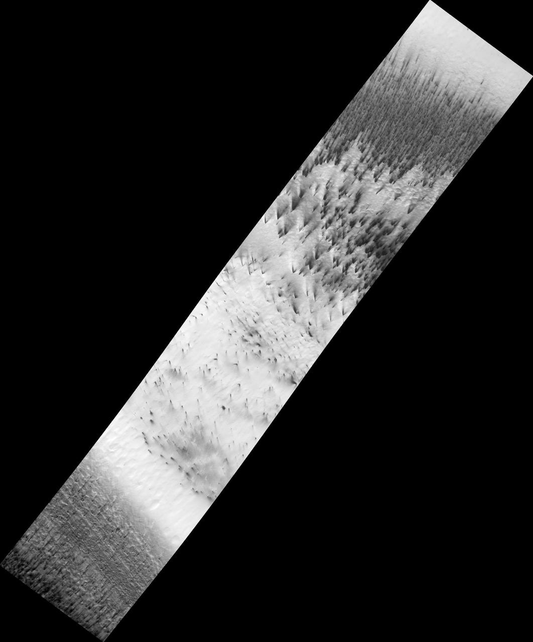
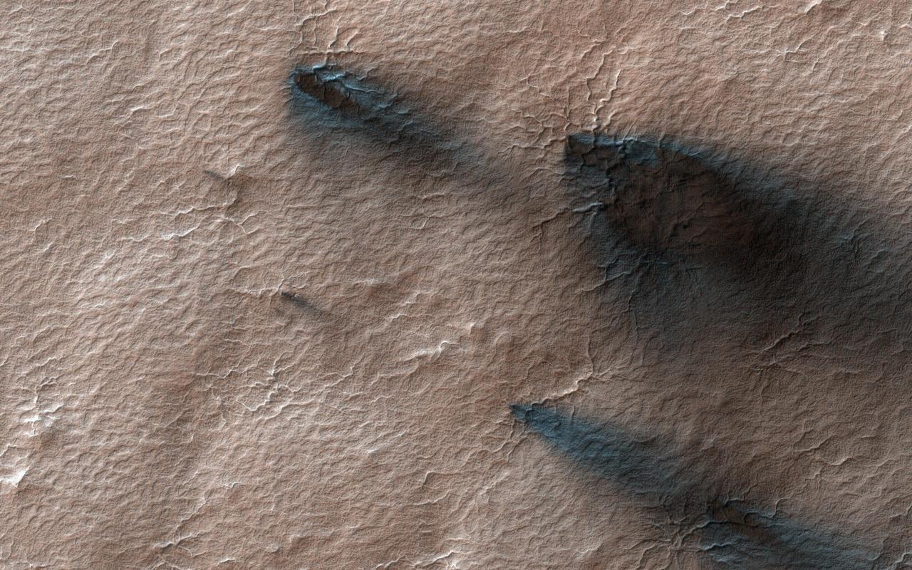
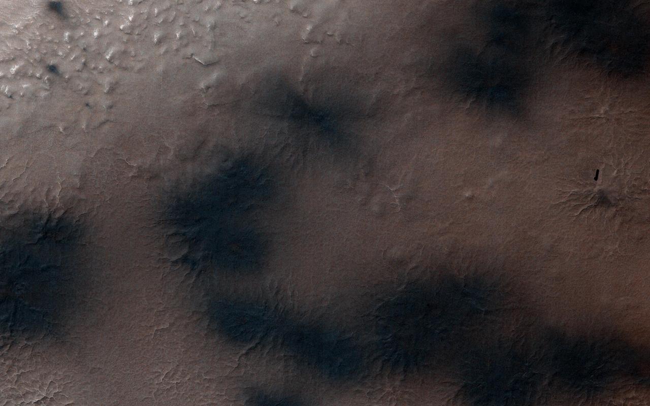
Both water and dry ice have a major role in sculpting Mars' surface at high latitudes. Water ice frozen in the soil splits the ground into polygons. Erosion of the channels forming the boundaries of the polygons by dry ice sublimating in the spring adds plenty of twists and turns to them. Spring activity is visible as the layer of translucent dry ice coating the surface develops vents that allow gas to escape. The gas carries along fine particles of material from the surface further eroding the channels. The particles drop to the surface in dark fan-shaped deposits. Sometimes the dark particles sink into the dry ice, leaving bright marks where the fans were originally deposited. Often the vent closes, then opens again, so we see two or more fans originating from the same spot but oriented in different directions as the wind changes. https://photojournal.jpl.nasa.gov/catalog/PIA25357
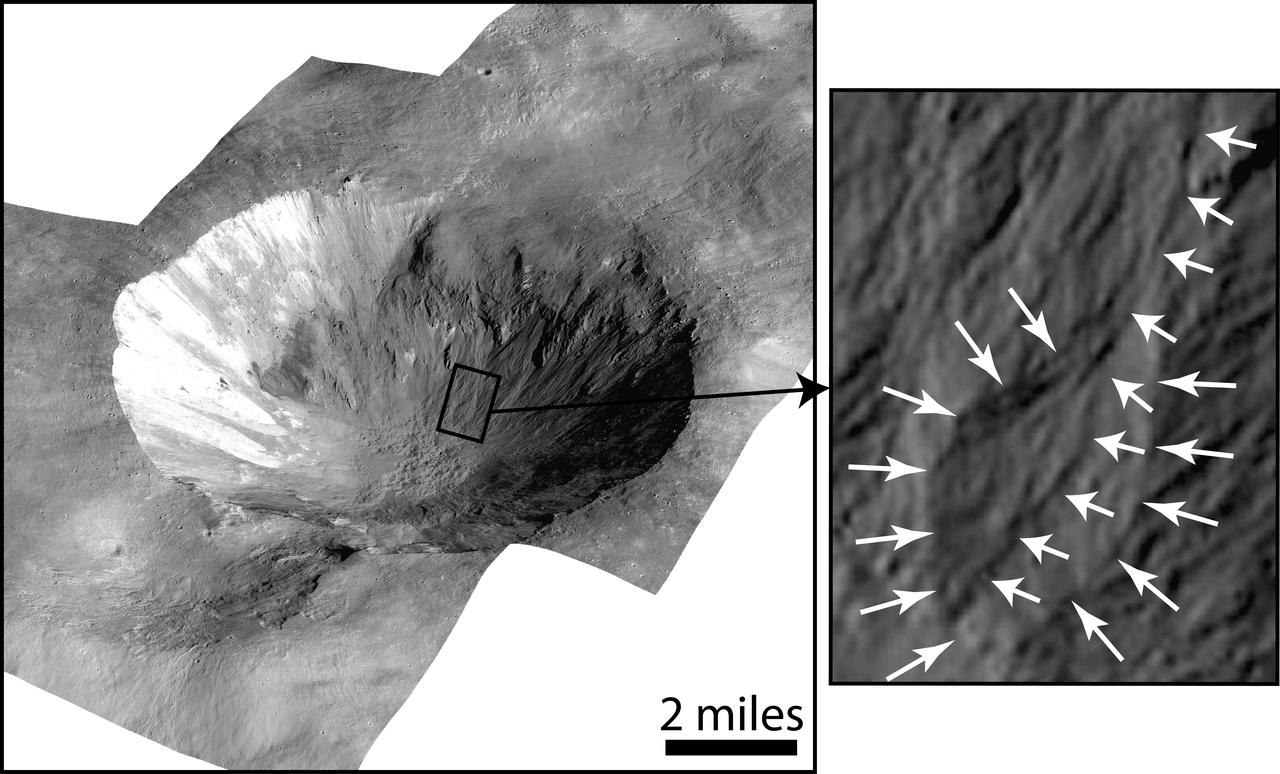
This image shows Cornelia Crater on the large asteroid Vesta. On the right is an inset image showing an example of curved gullies, indicated by the short white arrows, and a fan-shaped deposit, indicated by long white arrows. http://photojournal.jpl.nasa.gov/catalog/PIA19170
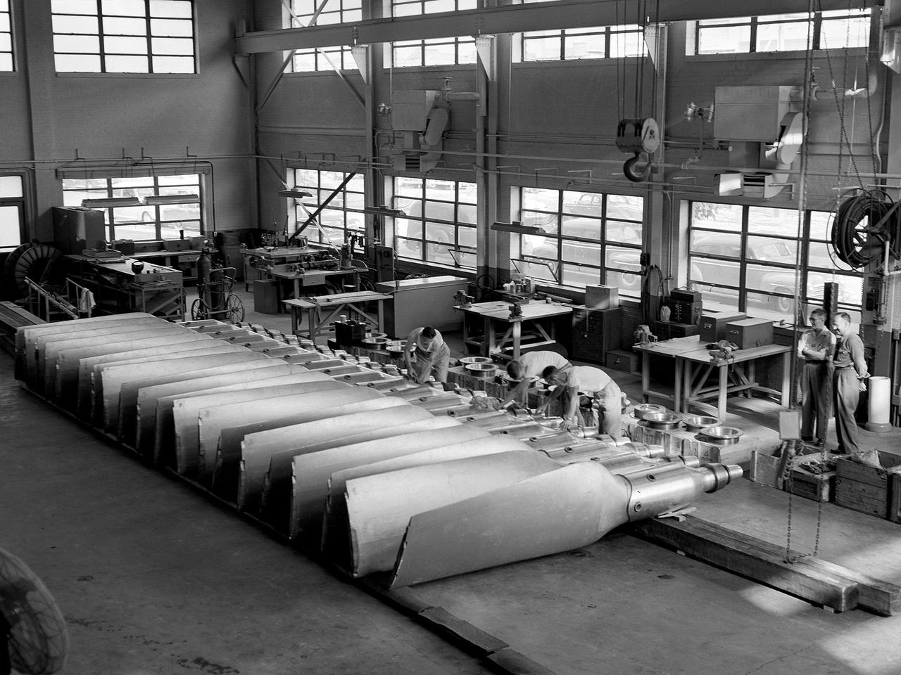
New wooden fan blades being prepared for installation in the Altitude Wind Tunnel at the National Advisory Committee for Aeronautics (NACA) Lewis Flight Propulsion Laboratory. The facility underwent a major upgrade in 1951 to increase its operating capacities in order to handle the new, more powerful turbojet engines being manufactured in the 1950s. The fan blades were prepared in the shop area, seen in this photograph, before being lowered through a hole in the tunnel and attached to the drive shaft. A new drive bearing and tail faring were also installed on the fan as part of this rehab project. A 12-bladed 31-foot-diameter spruce wood fan generated the 300 to 500 mile-per-hour airflow through the tunnel. An 18,000-horsepower General Electric induction motor located in the rear corner of the Exhauster Building drove the fan at 410 revolutions per minute. An extension shaft, sealed in the tunnel’s shell with flexible couplings that allowed for the movement of the shell, connected the motor to the fan. A bronze screen secured to the turning vanes protected the fan against damage from any engine parts sailing through the tunnel. Despite this screen the blades did become worn or cracked over time and had to be replaced.
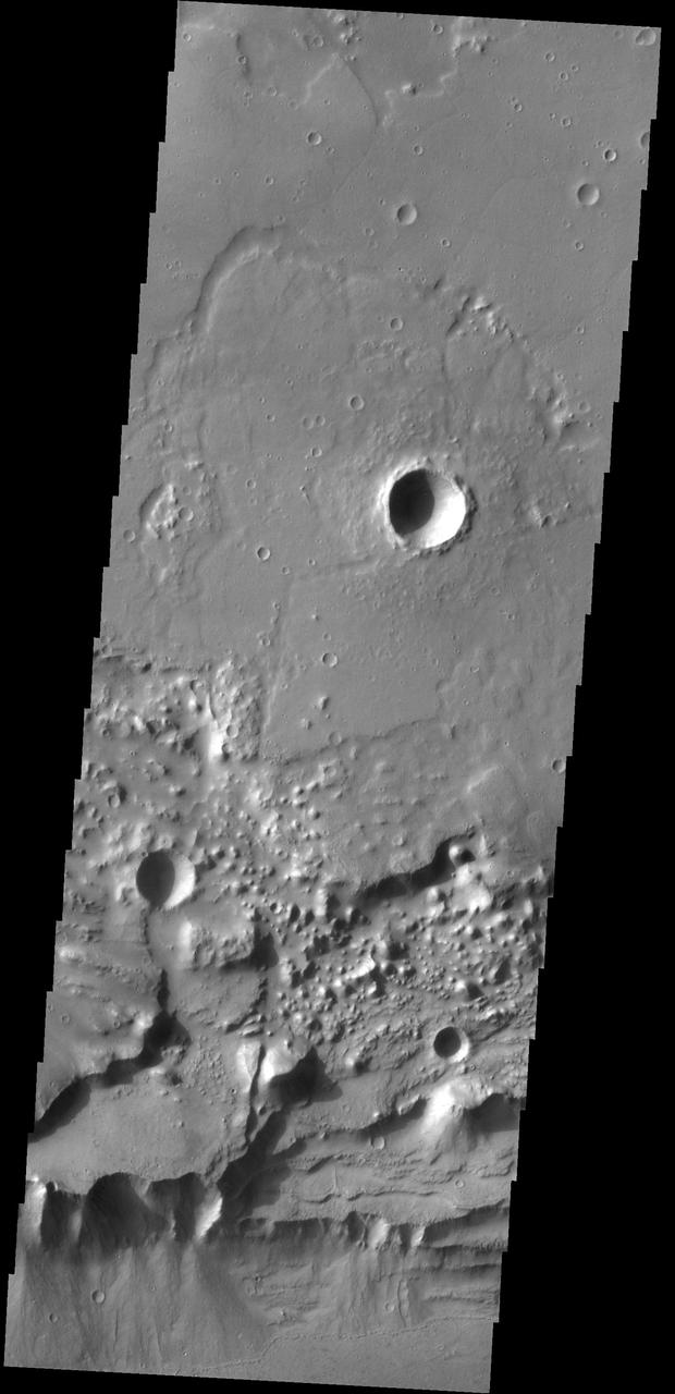
Bigbee is a 21 kilometer-diameter impact crater located on the northern rim of Holden crater in southern Margaritifer Terra, a region on Mars that is well known for its long record of water-rich activity as seen by NASA Mars Reconnaissance Orbiter. he rim of Bigbee has been heavily modified from its original form, presumably by water and wind. Material eroded and removed from Bigbee's rim was transported and deposited to the crater interior. Some of the darker-toned material near Bigbee's northern rim has been incorporated into fan-shaped deposits with distinct margins at the outer part. The fan surfaces appear to lack obvious layering and channels. The modification of Bigbee and other smaller craters on Holden's rim may have been contemporaneous with a proposed period of relatively late, water-driven activity that formed fans in Holden and other craters in Margaritifer Terra (see Grant and Wilson, 2012). Note: The cutout is 3.5-kilometer across and shows dark fan-like deposits on left side of image at the base of a light-toned scarp. http://photojournal.jpl.nasa.gov/catalog/PIA19296

3/4 rear view Ryan XV-5A lift-fan VSTOL airplane. Pictured with Tom Wills.
3/4 front view Ryan XV-5A lift-fan VSTOL airplane. Pictured with Tom Wills.
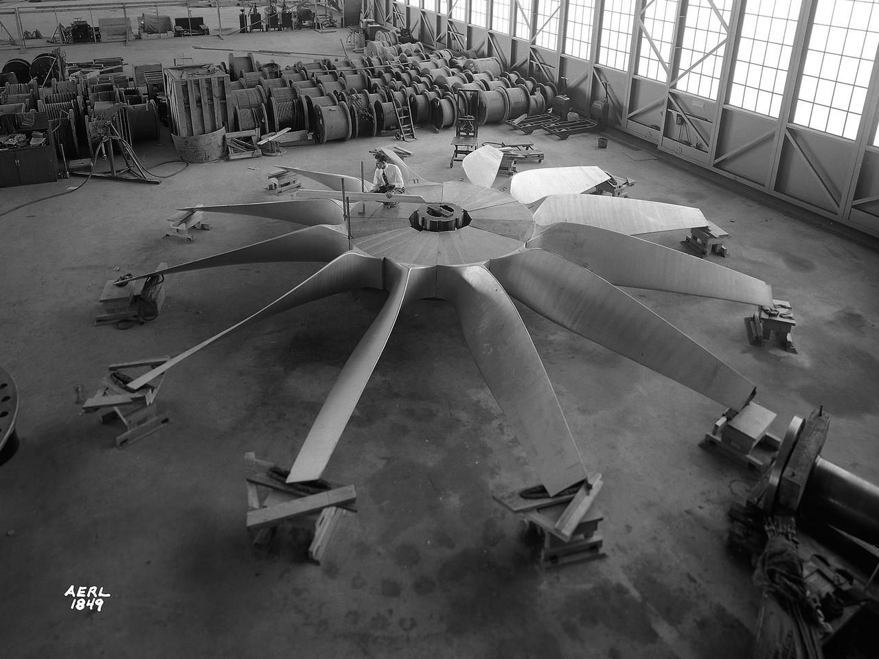
National Advisory Committee for Aeronautics (NACA) engineers assembled the Altitude Wind Tunnel’s (AWT) large wooden drive fan inside the hangar at the Aircraft Engine Research Laboratory. When it was built at the in the early 1940s the AWT was among the most complex test facilities ever designed. It was the first wind tunnel capable of operating full-scale engines under realistic flight conditions. This simulation included the reduction of air temperature, a decrease in air pressure, and the creation of an airstream velocity of up to 500 miles per hour. The AWT was constructed in 1942 and 1943. This photograph shows NACA engineers Lou Hermann and Jack Aust assembling the tunnel’s drive fan inside the hangar. The 12-bladed, 31-foot-diameter spruce wood fan would soon be installed inside the wind tunnel to create the high-speed airflow. This massive propeller was designed and constructed by the engine lab's design team at Langley Field. John Breisch, a Langley technician with several years of wind tunnel installation experience, arrived in Cleveland at the time of this photograph to supervise the fan assembly inside the hangar. He would return several weeks later to oversee the actual installation in the tunnel. The fan was driven at 410 revolutions per minute by an 18,000-horsepower General Electric induction motor that was located in the rear corner of the Exhauster Building. An extension shaft connected the motor to the fan. A bronze screen protected the fan against damage from failed engine parts sailing through the tunnel. Despite this screen the blades did become worn or cracked over time and had to be replaced. An entire new fan was installed in 1951.
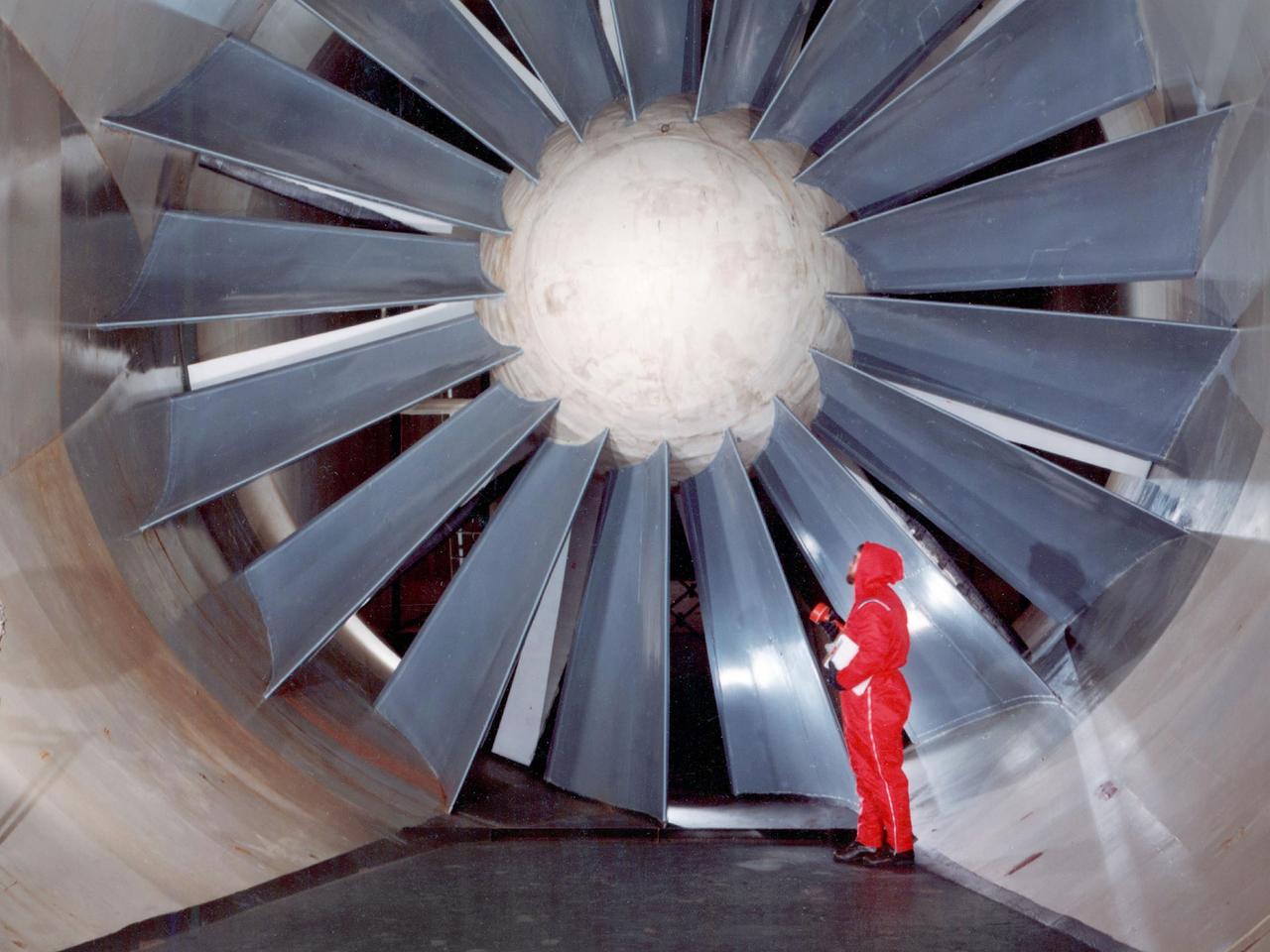
The drive fan for the Icing Research Tunnel at the National Aeronautics and Space Administration (NASA) Lewis Research Center in Cleveland, Ohio. The Lewis Icing Research Program, which began during World War II, utilized both research aircraft and the icing tunnel throughout the 1940s and 1950s. The research program was cancelled in 1958 as Lewis focused on space. The tunnel continued to be used occasionally for industrial customers in the 1960s and early 1970s. Lewis’ icing research was formally reinstituted just months before this photograph in 1978. The Icing Research Tunnel’s original 4100-horsepower induction motor was coupled directly to the 24-foot-diameter fan. Neoprene boots protected the leading edges of the 12 spruce fan blades. The system generated air speeds up to 300 miles per hour through the tunnel’s 6- by 9-foot test section. A large tail faring extended from the center of the fan to uniformly guide the airflow down the tunnel. NASA Headquarters ordered modifications to the Icing Research Tunnel in 1985 after wooden fan blades in a wind tunnel at Langley Research Center failed. Despite the fact that the large hub, seen in the center of the fan, provided an extra layer of protection against blade failure, Headquarters ordered the installation of a new set of wooden blades. The blades were ordered but not installed. The tunnel technicians instead agreed to inspect the fan after each run. A new 5000-horsepower motor was installed in 1987, and the original fan blades were finally replaced in 1993.
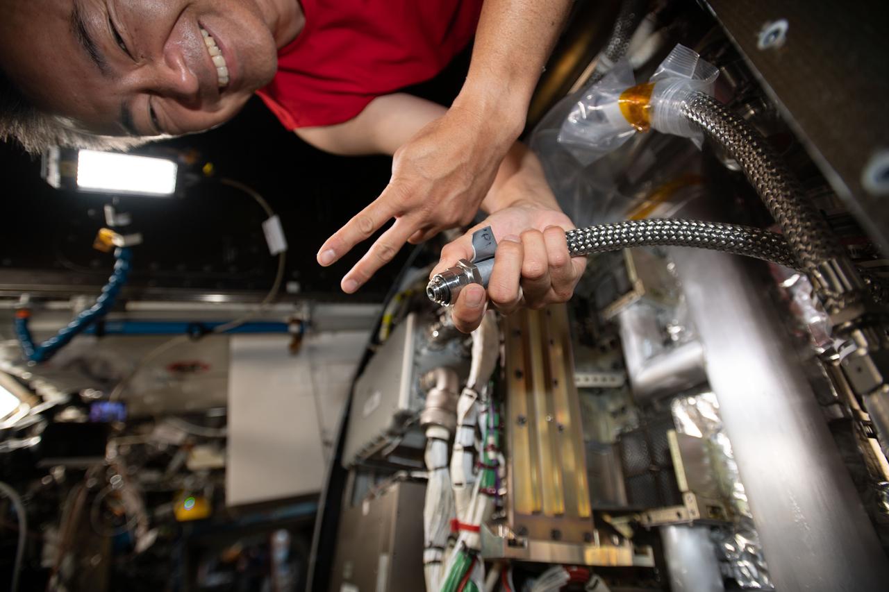
iss065e032225 (May 11, 2021) --- Expedition 65 Commander Akihiko Hoshide of the Japan Aerospace Exploration Agency replaces a science rack fan inside the International Space Station's U.S. Destiny laboratory.
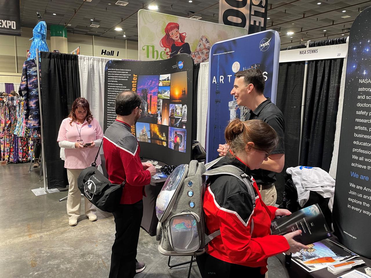
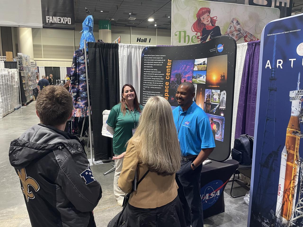
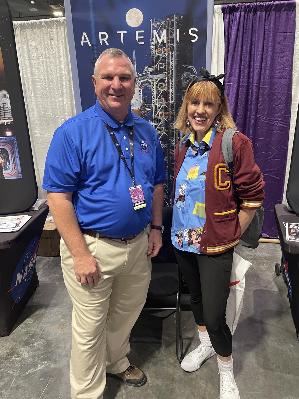
NASA reached out to inspire members of the Artemis Generation on Jan. 10-12, joining one of the largest comic con producers in the world to host an outreach booth at the 2025 FAN EXPO in New Orleans. Thousands of fans celebrating the best in pop culture such as movies, comics, and video gaming learned about NASA’s Stennis Space Center near Bay St. Louis, Mississippi, and its role to power space dreams.
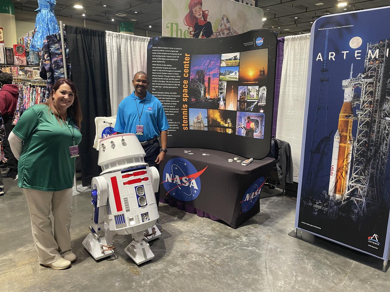
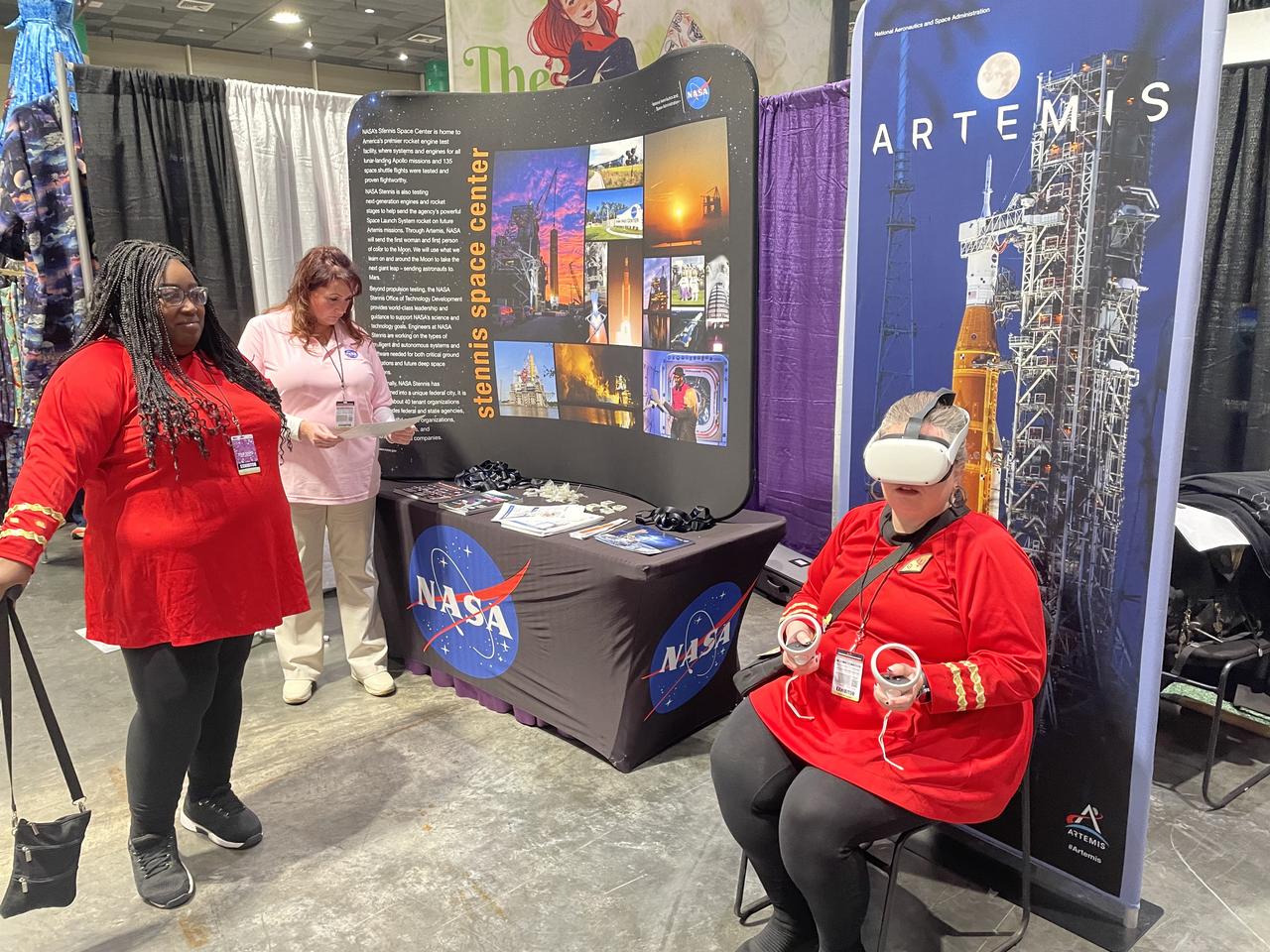
NASA reached out to inspire members of the Artemis Generation on Jan. 10-12, joining one of the largest comic con producers in the world to host an outreach booth at the 2025 FAN EXPO in New Orleans. Thousands of fans celebrating the best in pop culture such as movies, comics, and video gaming learned about NASA’s Stennis Space Center near Bay St. Louis, Mississippi, and its role to power space dreams.
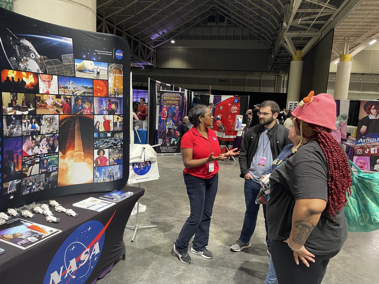
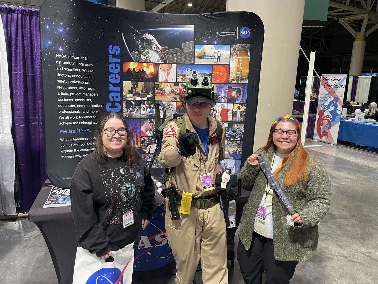
NASA reached out to inspire members of the Artemis Generation on Jan. 10-12, joining one of the largest comic con producers in the world to host an outreach booth at the 2025 FAN EXPO in New Orleans. Thousands of fans celebrating the best in pop culture such as movies, comics, and video gaming learned about NASA’s Stennis Space Center near Bay St. Louis, Mississippi, and its role to power space dreams.
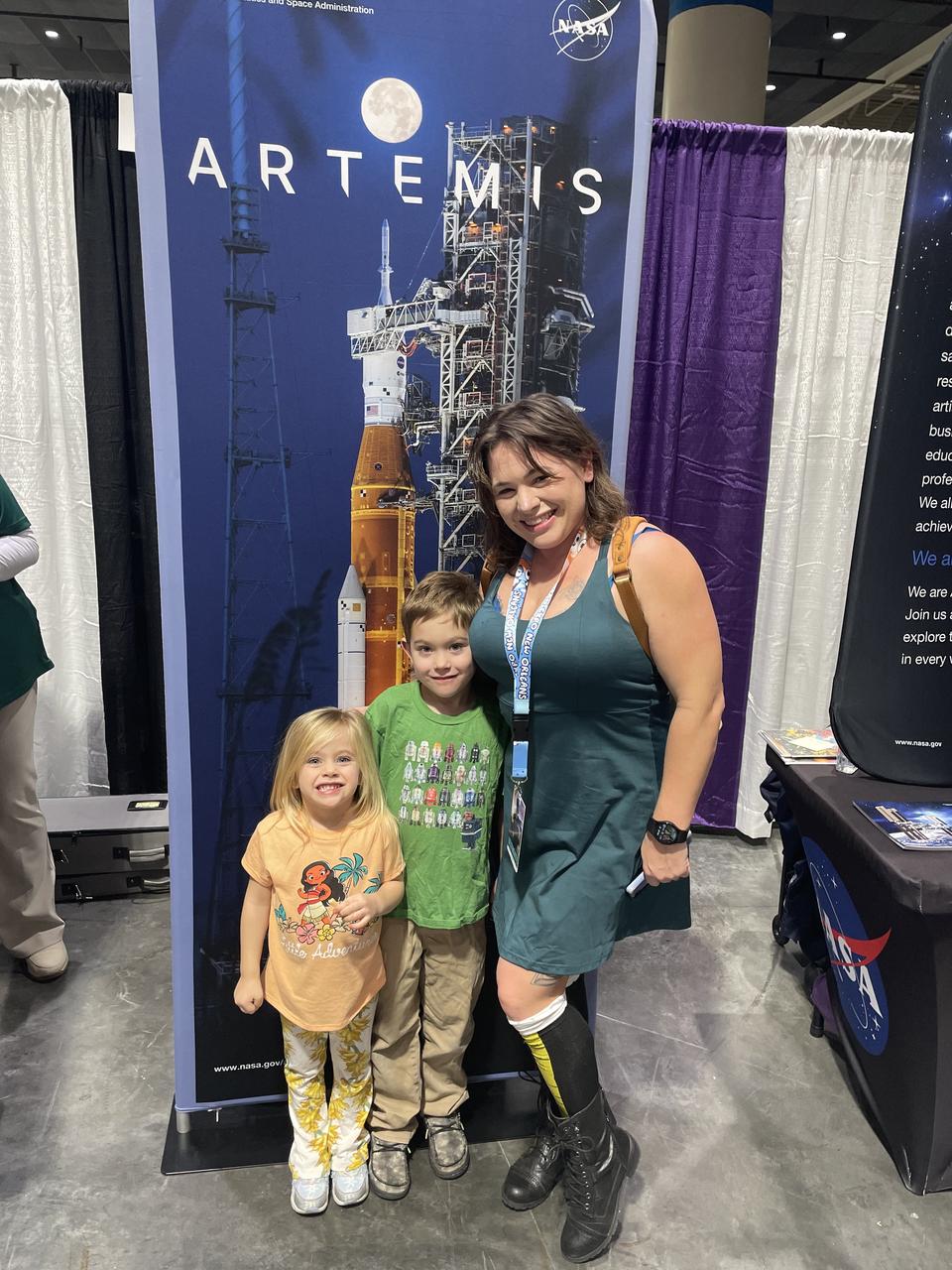
NASA reached out to inspire members of the Artemis Generation on Jan. 10-12, joining one of the largest comic con producers in the world to host an outreach booth at the 2025 FAN EXPO in New Orleans. Thousands of fans celebrating the best in pop culture such as movies, comics, and video gaming learned about NASA’s Stennis Space Center near Bay St. Louis, Mississippi, and its role to power space dreams.
NASA reached out to inspire members of the Artemis Generation on Jan. 10-12, joining one of the largest comic con producers in the world to host an outreach booth at the 2025 FAN EXPO in New Orleans. Thousands of fans celebrating the best in pop culture such as movies, comics, and video gaming learned about NASA’s Stennis Space Center near Bay St. Louis, Mississippi, and its role to power space dreams.
NASA reached out to inspire members of the Artemis Generation on Jan. 10-12, joining one of the largest comic con producers in the world to host an outreach booth at the 2025 FAN EXPO in New Orleans. Thousands of fans celebrating the best in pop culture such as movies, comics, and video gaming learned about NASA’s Stennis Space Center near Bay St. Louis, Mississippi, and its role to power space dreams.
NASA reached out to inspire members of the Artemis Generation on Jan. 10-12, joining one of the largest comic con producers in the world to host an outreach booth at the 2025 FAN EXPO in New Orleans. Thousands of fans celebrating the best in pop culture such as movies, comics, and video gaming learned about NASA’s Stennis Space Center near Bay St. Louis, Mississippi, and its role to power space dreams.
NASA reached out to inspire members of the Artemis Generation on Jan. 10-12, joining one of the largest comic con producers in the world to host an outreach booth at the 2025 FAN EXPO in New Orleans. Thousands of fans celebrating the best in pop culture such as movies, comics, and video gaming learned about NASA’s Stennis Space Center near Bay St. Louis, Mississippi, and its role to power space dreams.
Acoustic Casing Treatment Testing Completed in the W-8 Single Stage Axial Compressor Facility at NASA Glenn. Four different over-the-rotor acoustic casing treatment concepts were tested along with two baseline configurations. Testing included steady-aerodynamic measurements of fan performance, hotfilm turbulence measurements, and inlet acoustic measurements with an in-duct array.
Acoustic Casing Treatment Testing Completed in the W-8 Single Stage Axial Compressor Facility at NASA Glenn. Four different over-the-rotor acoustic casing treatment concepts were tested along with two baseline configurations. Testing included steady-aerodynamic measurements of fan performance, hotfilm turbulence measurements, and inlet acoustic measurements with an in-duct array.

Motor and propeller blades in 40x80ft wind tunnel. Six 40-foot-diameter fans, each powered by a 6000-horsepower electric motor maintained airflow at 230 mph or less (these are still tornado velocities).
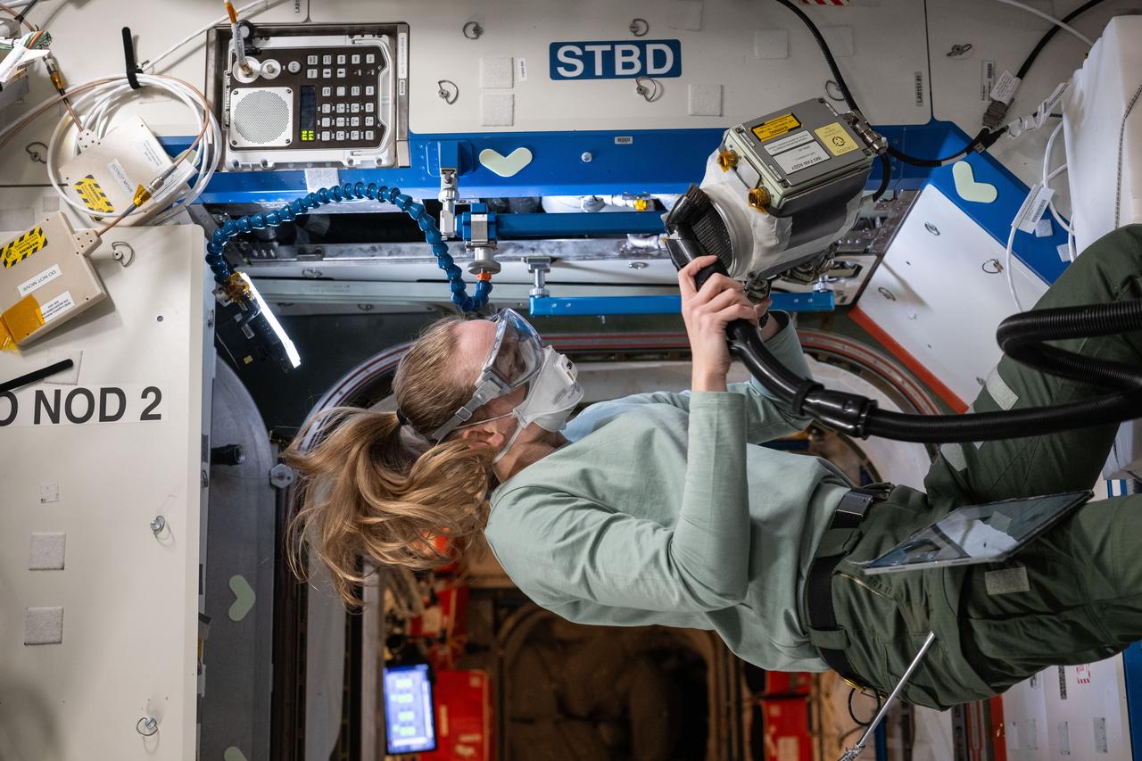
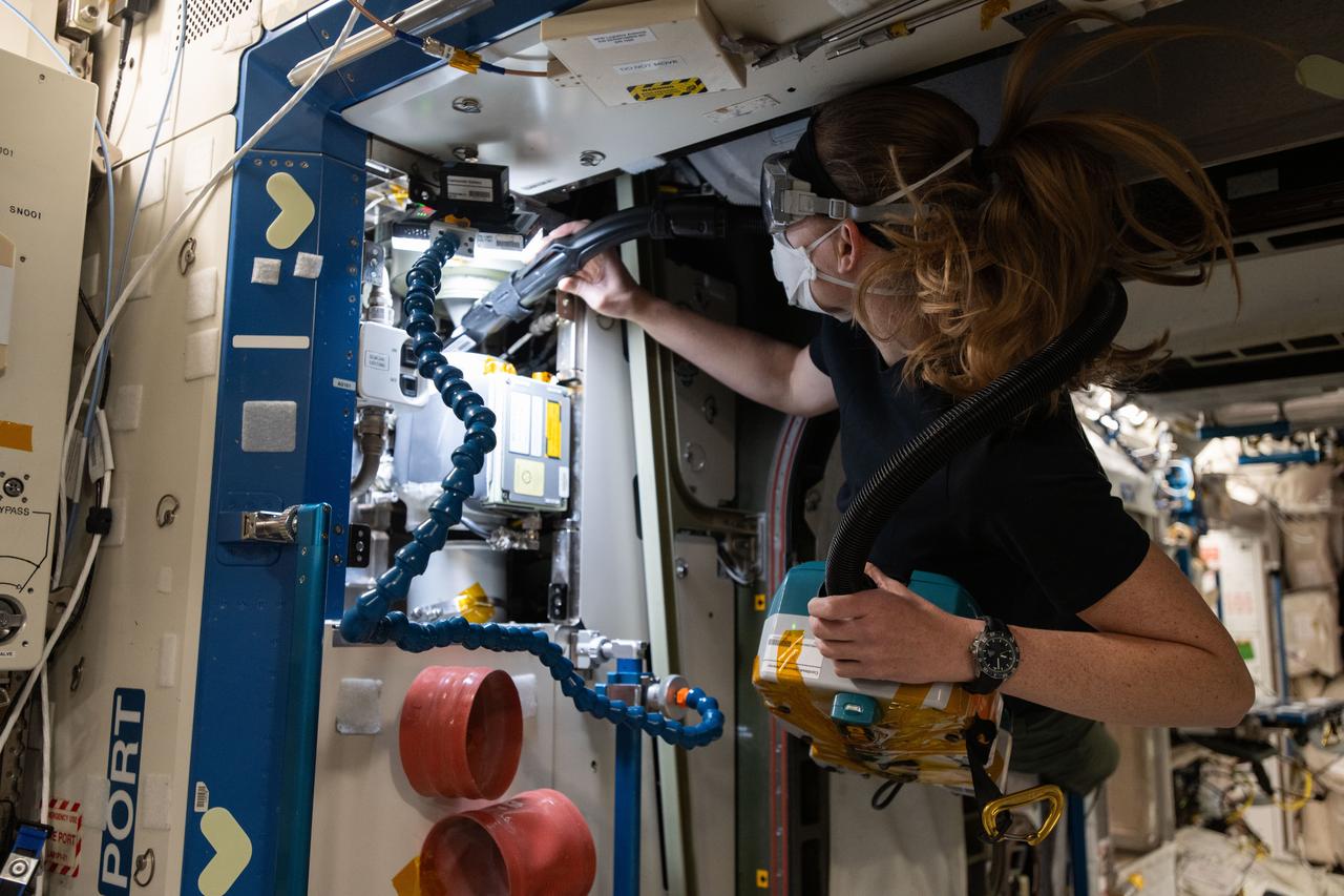
iss073e0176256 (June 11, 2025) --- NASA astronaut and Expedition 73 Flight Engineer Nichole Ayers inspects and cleans ventilation fans inside the International Space Station's Destiny laboratory module. The fans control the circulation of airflow between modules aboard the orbital outpost.
![This white, purple, and pink surface is located on the floor of an impact crater on the southeast rim of the larger Vinogradov Crater in southern Margaritifer Terra. The surface consists of what is left of a series of thin layers that subsequently eroded to create a "bullseye" pattern. The rough, etched appearance of the surface is similar-looking to deposits in other craters in the region and that are often associated with alluvial fans. The apparent ease and manner in which the materials are eroded relative to nearby fans and crater materials suggests they are fine-grained and the dominant agent of erosion is the wind. Although the origin of the deposits remains speculative, their physical character and common association with alluvial fans suggests they may be the result of deposition into a shallow lake or playa enabled by water flowing off the adjacent fan surfaces. The map is projected here at a scale of 25 centimeters (9.8 inches) per pixel. [The original image scale is 26 centimeters (10.2 inches) per pixel (with 1 x 1 binning); objects on the order of 78 centimeters (30.7 inches) across are resolved.] North is up. http://photojournal.jpl.nasa.gov/catalog/PIA21560](https://images-assets.nasa.gov/image/PIA21560/PIA21560~medium.jpg)
This white, purple, and pink surface is located on the floor of an impact crater on the southeast rim of the larger Vinogradov Crater in southern Margaritifer Terra. The surface consists of what is left of a series of thin layers that subsequently eroded to create a "bullseye" pattern. The rough, etched appearance of the surface is similar-looking to deposits in other craters in the region and that are often associated with alluvial fans. The apparent ease and manner in which the materials are eroded relative to nearby fans and crater materials suggests they are fine-grained and the dominant agent of erosion is the wind. Although the origin of the deposits remains speculative, their physical character and common association with alluvial fans suggests they may be the result of deposition into a shallow lake or playa enabled by water flowing off the adjacent fan surfaces. The map is projected here at a scale of 25 centimeters (9.8 inches) per pixel. [The original image scale is 26 centimeters (10.2 inches) per pixel (with 1 x 1 binning); objects on the order of 78 centimeters (30.7 inches) across are resolved.] North is up. http://photojournal.jpl.nasa.gov/catalog/PIA21560
This fan-shaped delta deposit is located in Holden Crater
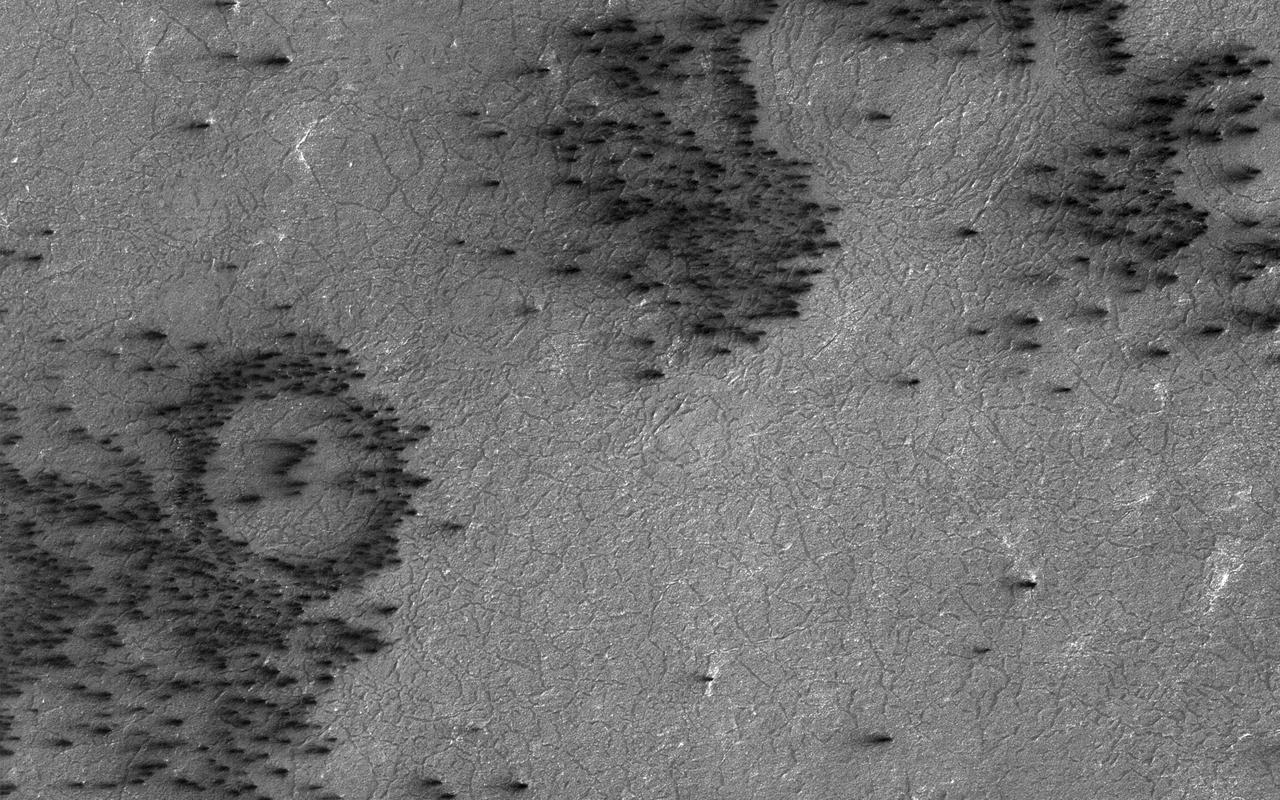
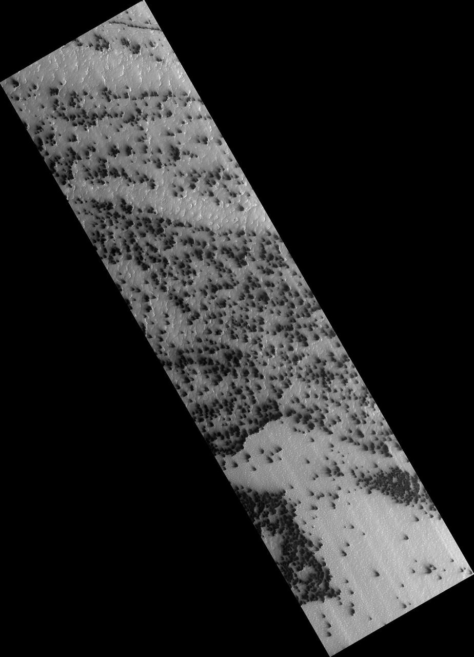
Gas under pressure will choose an easy escape route. In this image, the terrain is covered with a seasonal layer of dry ice. The weak spots, for gas sublimating from the bottom of the seasonal ice layer to escape, appear to be around craters, where the surface was broken and pulverized by an impact. Fans of surface material deposited on top of the seasonal ice layer show where the escape vents are. http://photojournal.jpl.nasa.gov/catalog/PIA21271
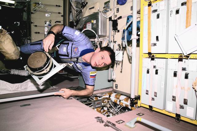
ISS01-E-5187 (January 2001) --- Cosmonaut Yuri P. Gidzenko, Expedition One Soyuz commander, floats through the Zvezda Service Module with a ventilator fan during maintenance work.
Department of Defense, DOD, NASA Prop Fan Interactions Project
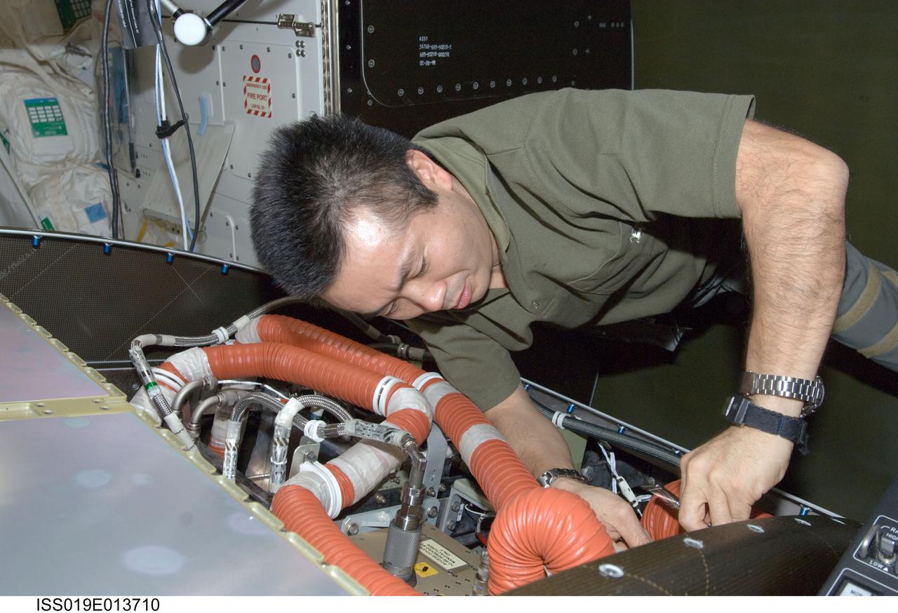
ISS019-E-013710 (5 May 2009) --- Japan Aerospace Exploration Agency (JAXA) astronaut Koichi Wakata, Expedition 19/20 flight engineer, cleans a fan filter on the Crew Health Care System Avionics Air Assembly (CHeCS AAA) in the Destiny laboratory of the International Space Station.

Eric Fanning, AIA President and CEO, delivers remarks at a reception following the dedication of the Apollo 1 monument, Thursday, June 2, 2022, in the Reception Hall of the Military Women’s Memorial at Arlington National Cemetery in Arlington, Va. The monument honors and memorializes the Apollo 1 crew of Virgil I. “Gus” Grissom, Edward H. White II, and Roger B. Chaffee. Photo Credit: (NASA/Bill Ingalls)
iss072e919611 (April 2, 2025) --- NASA astronaut and Expedition 72 Flight Engineer Nichole Ayers cleans ventilation system fans and inlets inside the International Space Station's Destiny labortory module.
This image, acquired by NASA Mars Reconnaissance Orbiter, shows there are a few more fans on the ridge as spring activity progresses in Inca City. In Inca City another week has passed, and there are a few more fans on the ridge. We are studying the sequence of spring activity with the help of citizen scientists at the Planetfour website, sponsored by Zooniverse. Citizens of planet Earth log on and identify and measure fans and blotches in the South polar region of Mars imaged by HiRISE. With their help we can study the polar weather by looking at how the fan directions change through the spring. We see how the number of fans and blotches depends on the thickness of the ice layer and how high the sun is in the sky. http://photojournal.jpl.nasa.gov/catalog/PIA18894

President and CEO of Aerospace Industries Association Eric Fanning gives remarks at the premiere of the film "Apollo 11: First Steps Edition", Tuesday, May 14, 2019 at the Smithsonian's National Air and Space Museum in Washington. Photo Credit: (NASA/Bill Ingalls)

Title: W-8 Fan Acoustic Casing Treatment Test on the Source Diagnostic Test Rotor Alone Hardware Program: Advanced Air Vehicles Program (AAVP) Project: Advanced Air Transport Technology (AATT) Sub-project: Aircraft Noise Reduction (ANR) Weekly Highlight: · Acoustic Casing Treatment Testing Completed in the W-8 Single Stage Axial Compressor Facility: Testing of Acoustic Casing Treatments on the Source Diagnostic Test (SDT) rotor alone hardware which had begun in early January was completed on Thursday, February 16th. Four different over-the-rotor acoustic casing treatment concepts were tested along with two baseline configurations. Testing included steady-aerodynamic measurements of fan performance, hotfilm turbulence measurements, and inlet acoustic measurements with an in-duct array. These measurements will be used to assess the aerodynamic and acoustic impact of fan acoustic casing treatments on a high bypass ratio fan at TRL 3. This test was the last of 3 planned tests of potential over-the-rotor acoustic casing treatments. The first treatment test was completed in the Normal Incidence Tube (NIT) at Langley Research Center (LaRC) in Fall 2015 and the second was completed on the Advanced Noise Control Fan (ANCF) in the Aero-Acoustic Propulsion Laboratory (AAPL) in Winter 2016. This work is supported by the Aircraft Noise Reduction (ANR) subproject of the Advanced Air Transport Technology (AATT) Project. (POC: LTV/ Rick Bozak 3-5160)
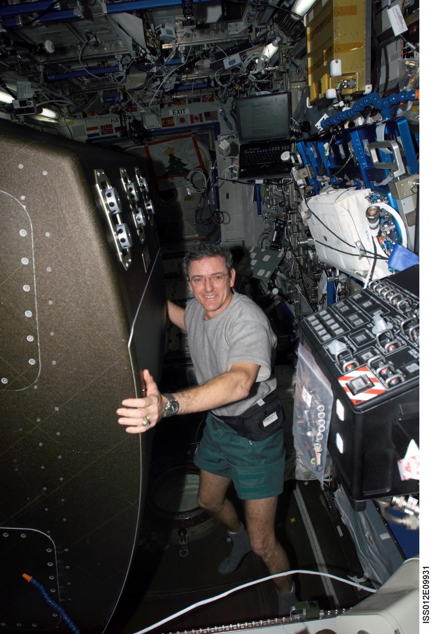
ISS012-E-09931 (1 December 2005) --- Astronaut William S. (Bill) McArthur Jr., Expedition 12 commander and NASA space station science officer, rotates the Crew Health Care System (CHeCS) rack back into position after cleaning the Avionics Air Assembly fan in the Destiny laboratory of the International Space Station.

Eric Fanning, AIA President and CEO speaks before a showing of the Project Mars Competition's short films winners and the Mars series, Monday, November 5, 2018 at National Geographic Society Headquarters in Washington. Photo Credit: (NASA/Aubrey Gemignani)

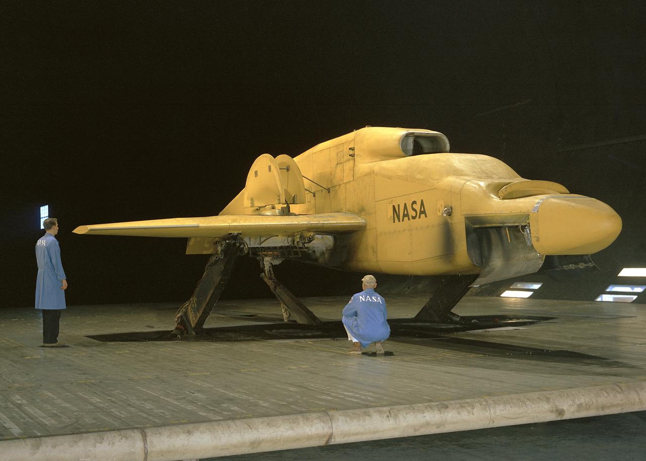
National Aeronautics and Space Administration (NASA) researcher John Carpenter inspects an aircraft model with a four-fan thrust reverser which would be studied in the 9- by 15-Foot Low Speed Wind Tunnel at the Lewis Research Center. Thrust reversers were introduced in the 1950s as a means for slowing high-speed jet aircraft during landing. Engineers sought to apply the technology to Vertical and Short Takeoff and Landing (VSTOL) aircraft in the 1970s. The new designs would have to take into account shorter landing areas, noise levels, and decreased thrust levels. A balance was needed between the thrust reverser’s efficiency, its noise generation, and the engine’s power setting. This model underwent a series of four tests in the 9- by 15-foot tunnel during April and May 1974. The model, with a high-wing configuration and no tail, was equipped with four thrust-reverser engines. The investigations included static internal aerodynamic tests on a single fan/reverser, wind tunnel isolated fan/reverser thrust tests, installation effects on a four-fan airplane model in a wind tunnel, and single reverser acoustic tests. The 9-by 15 was built inside the return leg of the 8- by 6-Foot Supersonic Wind Tunnel in 1968. The facility generates airspeeds from 0 to 175 miles per hour to evaluate the aerodynamic performance and acoustic characteristics of nozzles, inlets, and propellers, and investigate hot gas re-ingestion of advanced VSTOL concepts. John Carpenter was a technician in the Wind Tunnels Service Section of the Test Installations Division.

Eric Fanning, AIA President and CEO, left, Lance Bush, President and CEO of the Challenge Center, center, NASA Administrator Bill Nelson, left, are seen as they deliver remarks during the dedication of the Apollo 1 monument at Arlington National Cemetery, Thursday, June 2, 2022, in Arlington, Va. The monument honors and memorializes the Apollo 1 crew of Virgil I. “Gus” Grissom, Edward H. White II, and Roger B. Chaffee. Photo Credit: (NASA/Bill Ingalls)

Eric Fanning, AIA President and CEO, left, Lance Bush, President and CEO of the Challenge Center, center, NASA Administrator Bill Nelson, right, are seen as they deliver remarks during the dedication of the Apollo 1 monument at Arlington National Cemetery, Thursday, June 2, 2022, in Arlington, Va. The monument honors and memorializes the Apollo 1 crew of Virgil I. “Gus” Grissom, Edward H. White II, and Roger B. Chaffee. Photo Credit: (NASA/Bill Ingalls)
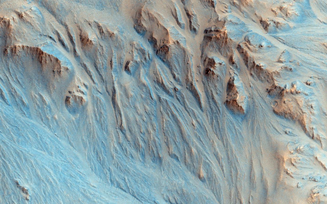
This image from NASA Mars Reconnaissance Orbiter shows several seemingly active gullies and their associated fans near the Argyre region. As gullies form on slopes, sediment can become deposited to form lobe-shaped fans. Gullies can form with flowing water, but don't have to: sometimes they can be formed by the dry flow of sand and dust grains. This HiRISE image shows several seemingly active gullies and their associated fans. These particular gullies have many fine channels that are resolved nicely with a high resolution image. http://photojournal.jpl.nasa.gov/catalog/PIA19286
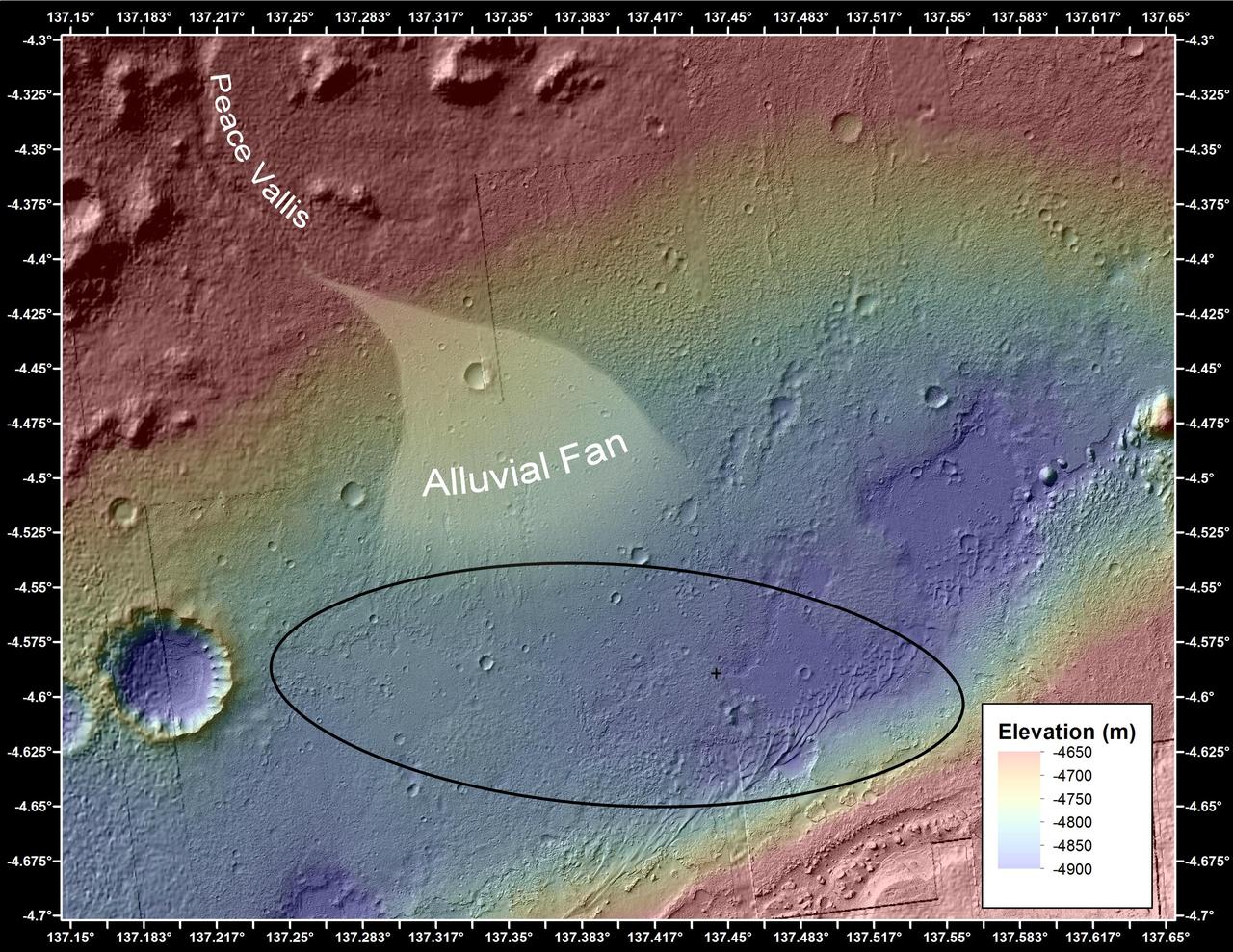
This image shows the topography, with shading added, around the area where NASA Curiosity rover landed. An alluvial fan, or fan-shaped deposit where debris spreads out downslope, has been highlighted in lighter colors for better viewing.
NASA 2001 Mars Odyssey captured this image of a channel entering Eberswalde Crater and depositing a fan-shaped delta on the crater floor.
A researcher examines the drive fan inside the Icing Research Tunnel at the National Advisory Committee for Aeronautics (NACA) Flight Propulsion Research Laboratory in Cleveland, Ohio. The facility was built in the mid-1940s to simulate the atmospheric conditions that caused ice to build up on aircraft. Carrier Corporation refrigeration equipment reduced the internal air temperature to -45⁰ F, and a spray bar system injected water droplets into the air stream. The 24-foot diameter drive fan, seen in this photograph, created air flow velocities up to 400 miles per hour. The 1950s were prime years for the Icing Research Tunnel. NACA engineers had spent the 1940s trying to resolve the complexities of the spray bar system. The final system put into operation in 1950 included six horizontal spray bars with 80 nozzles that produced a 4- by 4-foot cloud in the test section. The icing tunnel was used for extensive testing of civilian and military aircraft components in the 1950s. The NACA also launched a major investigation of the various methods of heating leading edge surfaces. The hot-air anti-icing technology used on today’s commercial transports was largely developed in the facility during this period. Lewis researchers also made significant breakthroughs with icing on radomes and jet engines. Although the Icing Research Tunnel yielded major breakthroughs in the 1950s, the Lewis icing research program began tapering off as interest in the space program grew. The icing tunnel’s use declined in 1956 and 1957. The launch of Sputnik in October 1957 signaled the end of the facility’s operation. The icing staff was transferred to other research projects and the icing tunnel was temporarily mothballed.