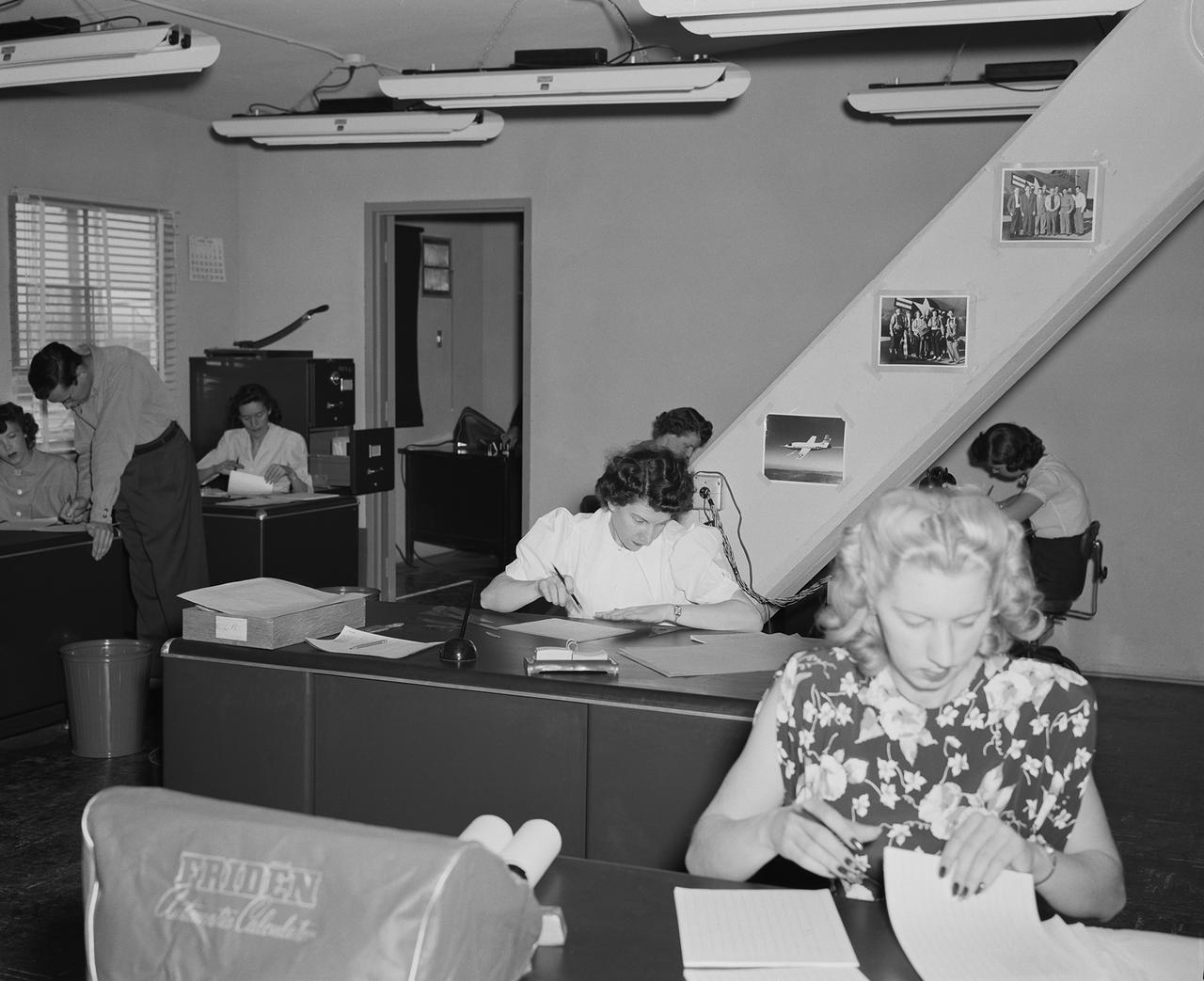
NACA women computers had degrees in mathematics or taught math before they were hired. They reduced film data and plotted it for the engineers.
![KENNEDY SPACE CENTER, FLA. - These towers are part of one of the world’s highest performing visual film analysis systems, developed to review and analyze previous shuttle flight data in preparation for the shuttle fleet’s return to flight. The system is being used today for another purpose. NASA has permitted its use in helping to analyze a film that shows a recent kidnapping in progress in Florida. Developed by NASA, United Space Alliance (USA) and Silicon Graphics Inc., the system allows multiple-person collaboration, highly detailed manipulation and evaluation of specific imagery. The system is housed in the Image Analysis Facility inside the Vehicle Assembly Building. [Photo taken Aug. 15, 2003, courtesy of Terry Wallace, SGI ]](https://images-assets.nasa.gov/image/KSC-04pd0152/KSC-04pd0152~medium.jpg)
KENNEDY SPACE CENTER, FLA. - These towers are part of one of the world’s highest performing visual film analysis systems, developed to review and analyze previous shuttle flight data in preparation for the shuttle fleet’s return to flight. The system is being used today for another purpose. NASA has permitted its use in helping to analyze a film that shows a recent kidnapping in progress in Florida. Developed by NASA, United Space Alliance (USA) and Silicon Graphics Inc., the system allows multiple-person collaboration, highly detailed manipulation and evaluation of specific imagery. The system is housed in the Image Analysis Facility inside the Vehicle Assembly Building. [Photo taken Aug. 15, 2003, courtesy of Terry Wallace, SGI ]
![KENNEDY SPACE CENTER, FLA. - One of the world’s highest performing visual film analysis systems, developed to review and analyze previous shuttle flight data (shown here) in preparation for the shuttle fleet’s return to flight, is being used today for another purpose. NASA has permitted its use in helping to analyze a film that shows a recent kidnapping in progress in Florida. The system, developed by NASA, United Space Alliance (USA) and Silicon Graphics Inc., allows multiple-person collaboration, highly detailed manipulation and evaluation of specific imagery. The system is housed in the Image Analysis Facility inside the Vehicle Assembly Building. [Photo taken Aug. 15, 2003, courtesy of Terry Wallace, SGI ]](https://images-assets.nasa.gov/image/KSC-04pd0150/KSC-04pd0150~medium.jpg)
KENNEDY SPACE CENTER, FLA. - One of the world’s highest performing visual film analysis systems, developed to review and analyze previous shuttle flight data (shown here) in preparation for the shuttle fleet’s return to flight, is being used today for another purpose. NASA has permitted its use in helping to analyze a film that shows a recent kidnapping in progress in Florida. The system, developed by NASA, United Space Alliance (USA) and Silicon Graphics Inc., allows multiple-person collaboration, highly detailed manipulation and evaluation of specific imagery. The system is housed in the Image Analysis Facility inside the Vehicle Assembly Building. [Photo taken Aug. 15, 2003, courtesy of Terry Wallace, SGI ]
![KENNEDY SPACE CENTER, FLA. - One of the world’s highest performing visual film analysis systems, developed to review and analyze previous shuttle flight data (shown here) in preparation for the shuttle fleet’s return to flight, is being used today for another purpose. NASA has permitted its use in helping to analyze a film that shows a recent kidnapping in progress in Florida. The system, developed by NASA, United Space Alliance (USA) and Silicon Graphics Inc., allows multiple-person collaboration, highly detailed manipulation and evaluation of specific imagery. The system is housed in the Image Analysis Facility inside the Vehicle Assembly Building. [Photo taken Aug. 15, 2003, courtesy of Terry Wallace, SGI ]](https://images-assets.nasa.gov/image/KSC-04pd0151/KSC-04pd0151~medium.jpg)
KENNEDY SPACE CENTER, FLA. - One of the world’s highest performing visual film analysis systems, developed to review and analyze previous shuttle flight data (shown here) in preparation for the shuttle fleet’s return to flight, is being used today for another purpose. NASA has permitted its use in helping to analyze a film that shows a recent kidnapping in progress in Florida. The system, developed by NASA, United Space Alliance (USA) and Silicon Graphics Inc., allows multiple-person collaboration, highly detailed manipulation and evaluation of specific imagery. The system is housed in the Image Analysis Facility inside the Vehicle Assembly Building. [Photo taken Aug. 15, 2003, courtesy of Terry Wallace, SGI ]
![KENNEDY SPACE CENTER, FLA. - One of the world’s highest performing visual film analysis systems, developed to review and analyze previous shuttle flight data (shown here) in preparation for the shuttle fleet’s return to flight, is being used today for another purpose. NASA has permitted its use in helping to analyze a film that shows a recent kidnapping in progress in Florida. The system, developed by NASA, United Space Alliance (USA) and Silicon Graphics Inc., allows multiple-person collaboration, highly detailed manipulation and evaluation of specific imagery. The system is housed in the Image Analysis Facility inside the Vehicle Assembly Building. [Photo taken Aug. 15, 2003, courtesy of Terry Wallace, SGI ]](https://images-assets.nasa.gov/image/KSC-04pd0154/KSC-04pd0154~medium.jpg)
KENNEDY SPACE CENTER, FLA. - One of the world’s highest performing visual film analysis systems, developed to review and analyze previous shuttle flight data (shown here) in preparation for the shuttle fleet’s return to flight, is being used today for another purpose. NASA has permitted its use in helping to analyze a film that shows a recent kidnapping in progress in Florida. The system, developed by NASA, United Space Alliance (USA) and Silicon Graphics Inc., allows multiple-person collaboration, highly detailed manipulation and evaluation of specific imagery. The system is housed in the Image Analysis Facility inside the Vehicle Assembly Building. [Photo taken Aug. 15, 2003, courtesy of Terry Wallace, SGI ]
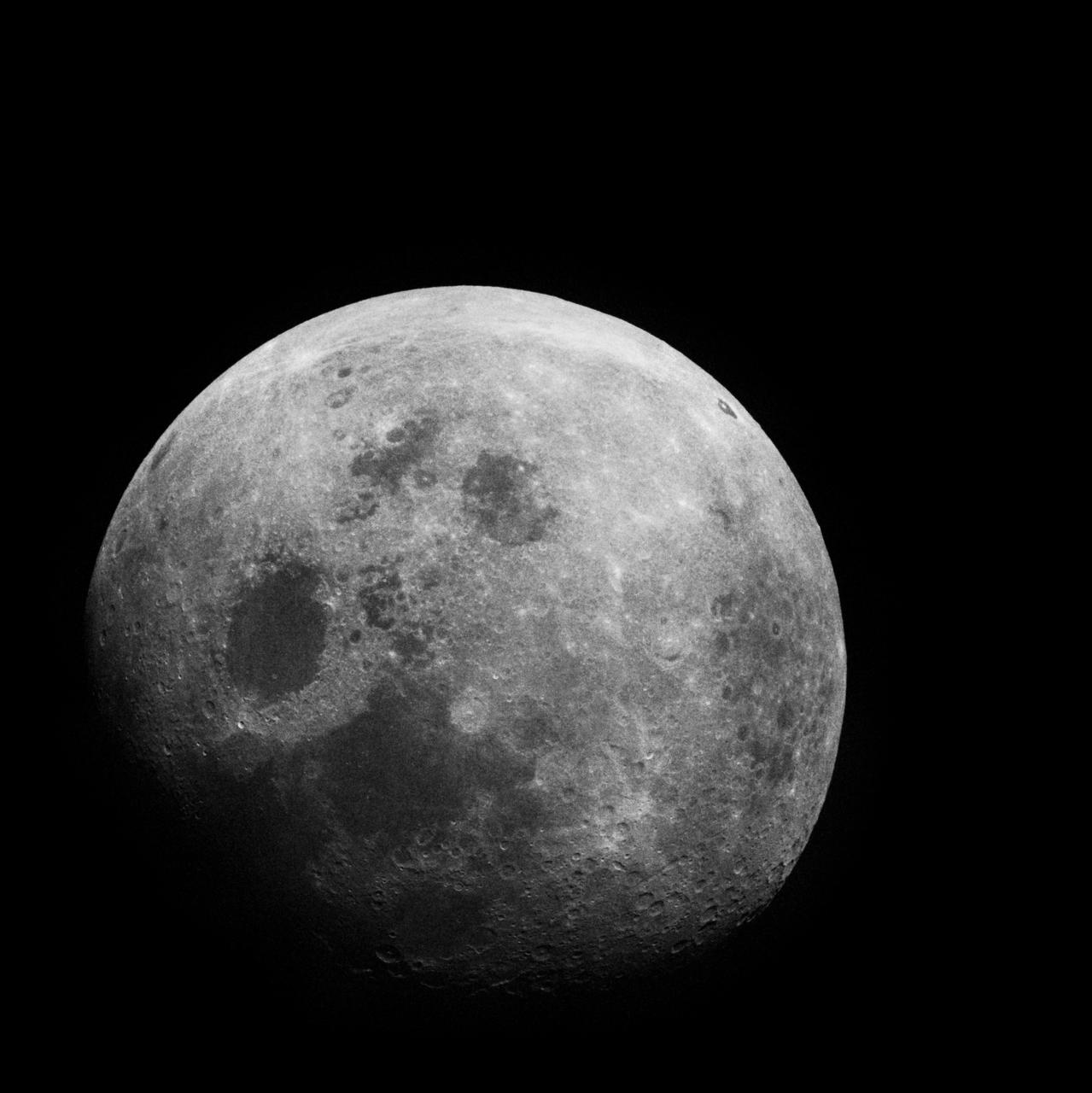
Apollo 8, Entire Moon. Possible Filter. Taken during the Transearth Coast (TEC). Original Film Magazine was labeled G. Camera Data: 70mm Hasselblad. Film Type: Kodak SO-2458 Black and White,ASA 2000. December 21-27,1968.

Apollo 7,Cumulus,alto-cumulus,cirrus clouds. Very high oblique. Cloud Cover 50%. Original film magazine was labeled S. Camera Data: Hasselblad 500-C; Lens: Zeiss Planar,F/2.8,80mm; Film Type: Kodak SO-121,Aerial Ektachrome; Filter: Wratten 2A. Flight Date: October 11-12. 1968.
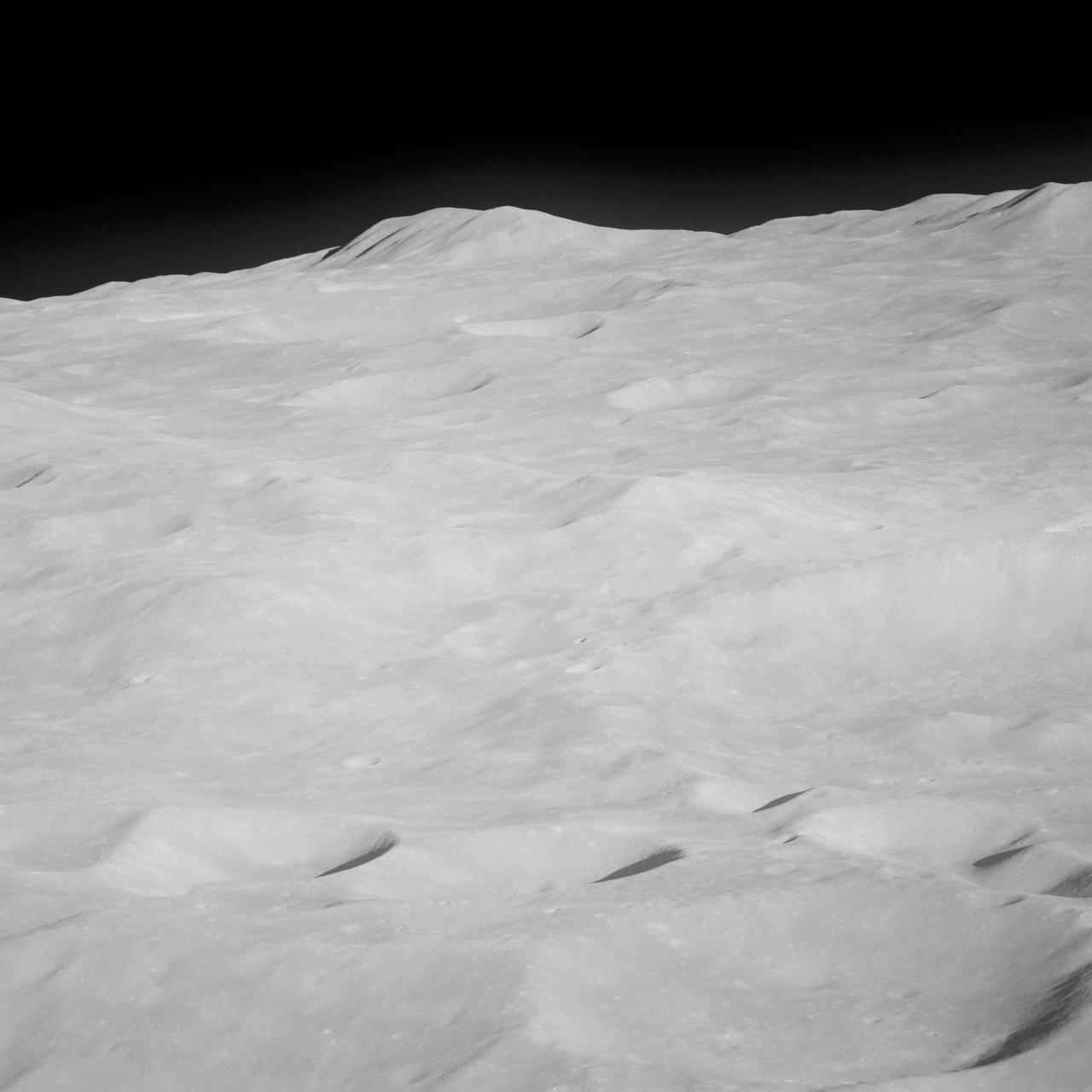
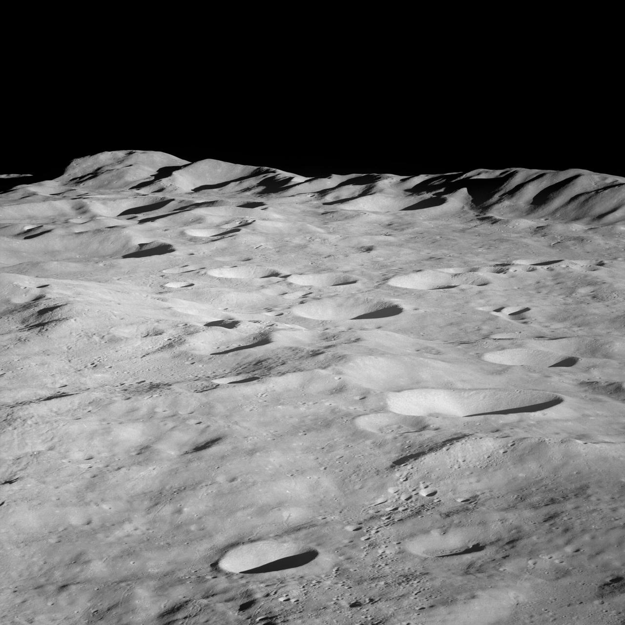
Apollo 8,Moon, Latitude 15 degrees South,Longitude 170 degrees West. Camera Tilt Mode: High Oblique. Direction: Southeast. Sun Angle 17 degrees. Original Film Magazine was labeled E. Camera Data: 70mm Hasselblad; F-Stop: F-5.6; Shutter Speed: 1/250 second. Film Type: Kodak SO-3400 Black and White,ASA 40. Other Photographic Coverage: Lunar Orbiter 1 (LO I) S-3. Flight Date: December 21-27,1968.
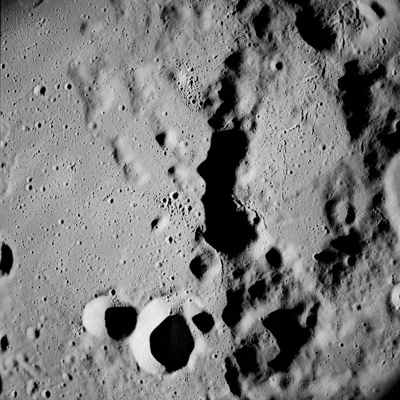
Apollo 8,Farside of Moon. Image taken on Revolution 4. Camera Tilt Mode: Vertical Stereo. Sun Angle: 13. Original Film Magazine was labeled D. Camera Data: 70mm Hasselblad. Lens: 80mm; F-Stop: F/2.8; Shutter Speed: 1/250 second. Film Type: Kodak SO-3400 Black and White,ASA 40. Flight Date: December 21-27,1968.
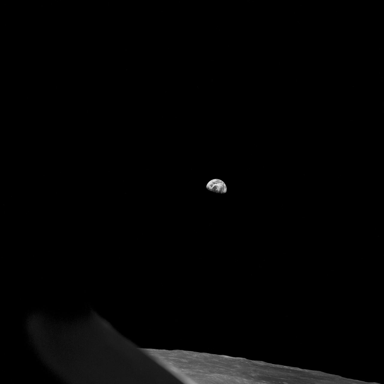
Apollo 8,Earth and Lunar Horizon. Image taken on Revolution 10 during Transearth Injection (TEI). Original Film Magazine was labeled D. Camera Data: 70mm Hasselblad. Lens: 80mm; F-Stop: F/11; Shutter Speed: 1/250 second. Film Type: Kodak SO-3400 Black and White,ASA 40. Flight Date: December 21-27,1968.
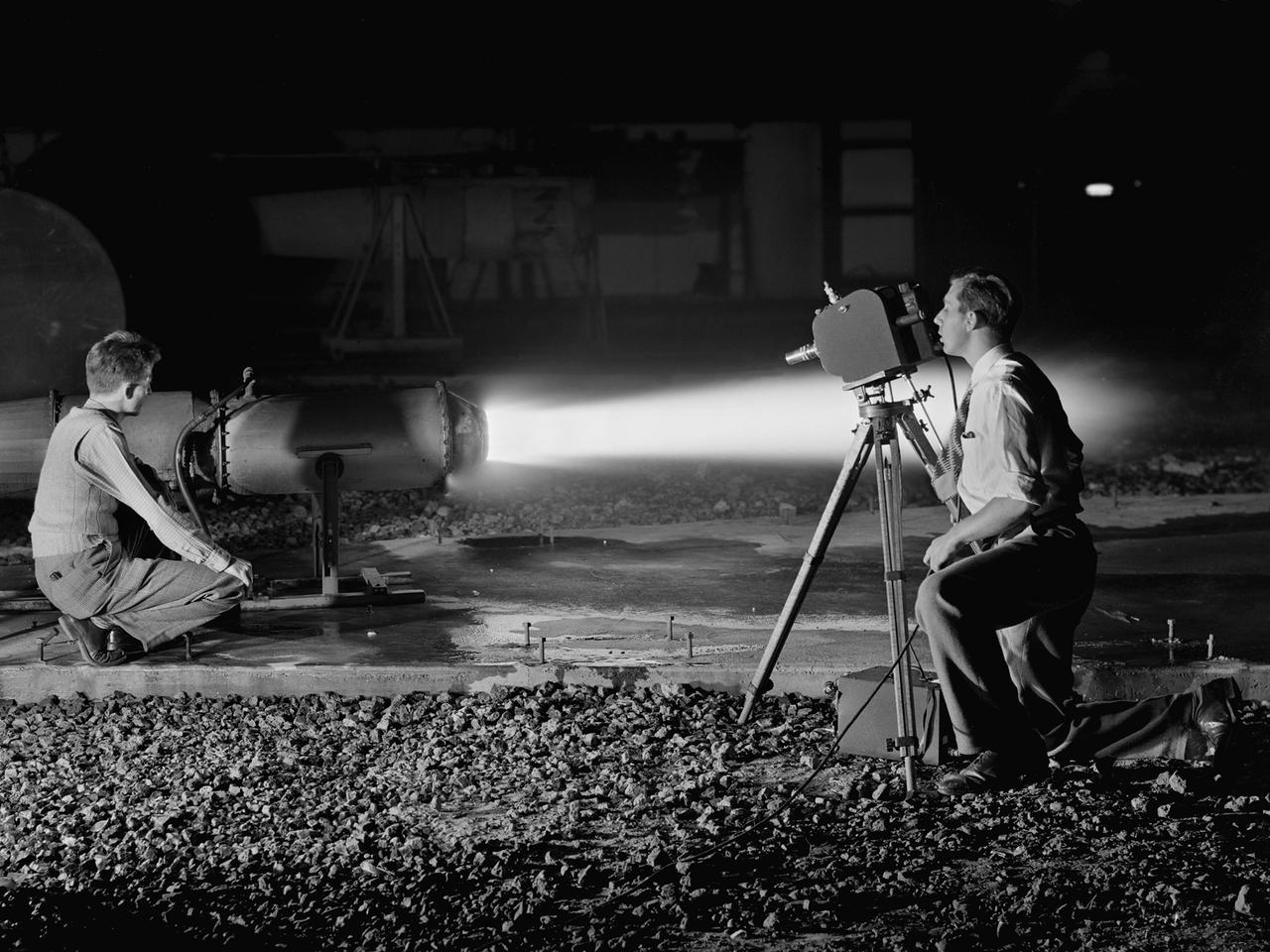
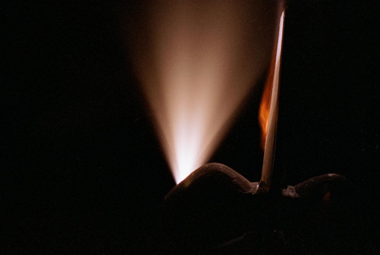
A National Advisory Committee for Aeronautics (NACA) photographer films the test of a ramjet engine at the Lewis Flight Propulsion Laboratory. The laboratory had an arsenal of facilities to test the engines and their components, and immersed itself in the study of turbojet and ramjet engines during the mid-1940s. Combustion, fuel injection, flameouts, and performance at high altitudes were of particular interest to researchers. They devised elaborate schemes to instrument the engines in order to record temperature, pressure, and other data. Many of the tests were also filmed so Lewis researchers could visually review the combustion performance along with the data. The photographer in this image was using high-speed film to document a thrust augmentation study at Lewis’ Jet Static Propulsion Laboratory. The ramjet in this photograph was equipped with a special afterburner as part of a general effort to improve engine performance. Lewis’ Photo Lab was established in 1942. The staff was expanded over the next few years as more test facilities became operational. The Photo Lab’s staff and specialized equipment have been key research tools for decades. They accompany pilots on test flights, use high-speed cameras to capture fleeting processes like combustion, and work with technology, such as the Schlieren camera, to capture supersonic aerodynamics. In addition, the group has documented construction projects, performed publicity work, created images for reports, and photographed data recording equipment.
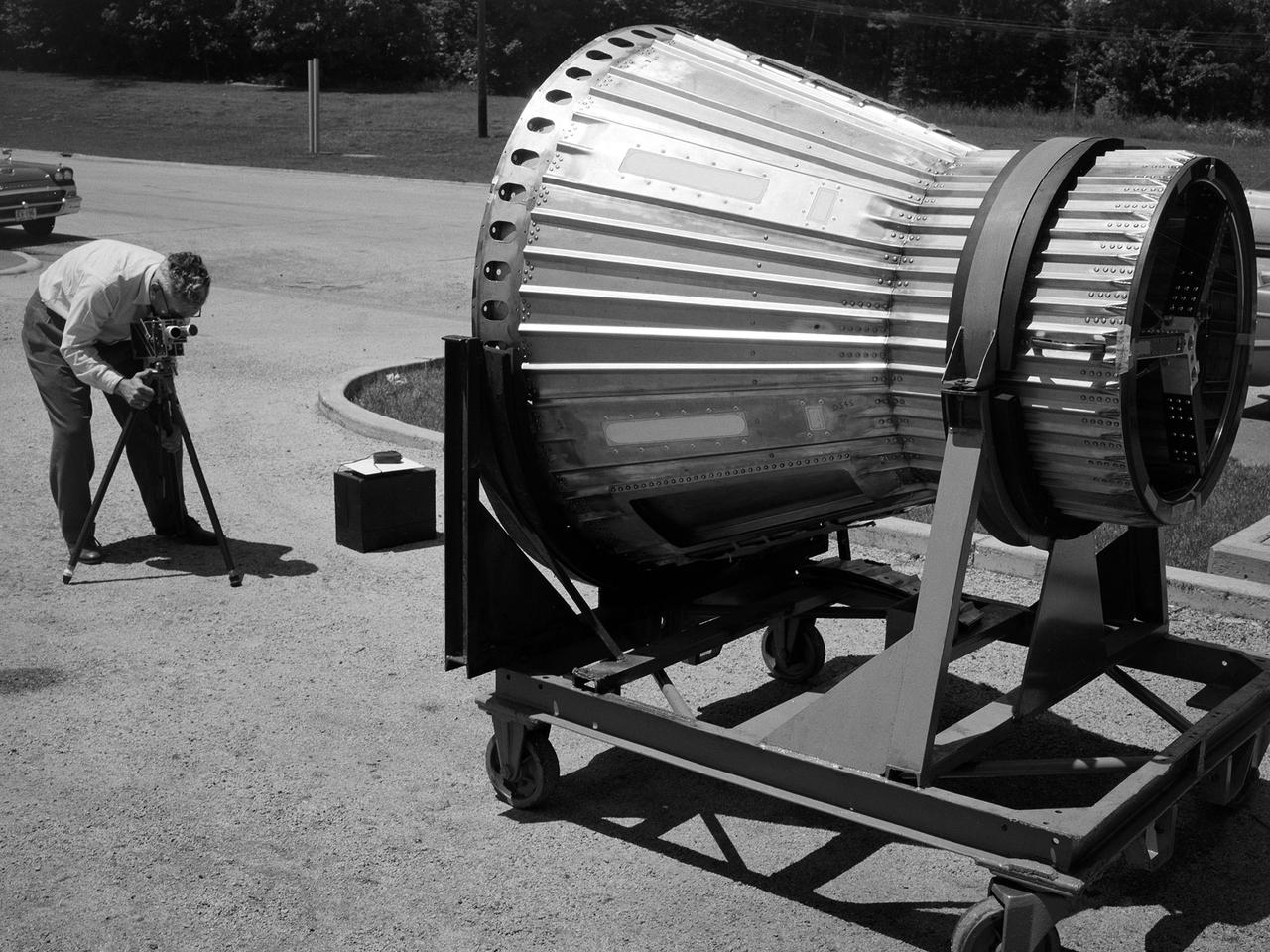
National Aeronautics and Space Administration (NASA) photographer Arthur Laufman sets up a camera to film a Mercury capsule that was constructed by the Lewis Research Center staff. Lewis engineers and mechanics built two of the capsules for the upcoming Big Joe launches in September 1959. Big Joe was an attempt early in Project Mercury to use a full-scale Atlas booster to simulate the reentry of a mock-up Mercury capsule without actually placing it in orbit. The Photographic Branch, referred to as the Photo Lab, was part of the center’s Technical Reports Division. Originally the group performed normal and high-speed still image and motion picture photography. The photographers documented construction, performed publicity work, created images for reports, photographed data on manometer boards, and recorded test footage. Laufman joined the Photo Lab staff in 1948 and began producing full-length technical films as a tool to educate those outside of the agency on the research being conducted at Lewis. He worked with engineers to determine proper subjects for these films and develop a script. Laufman not only filmed tests, but also supporting footage of facilities, models, and staff members. He then edited the footage and added audio, visuals, and narration. The film masters were assigned standard identification numbers and add to the Photo Lab’s catalogue.
Apollo 8,Moon,Target of Opportunity (T/O) 10, Various targets. Latitude 18 degrees South,Longitude 163.50 degrees West. Camera Tilt Mode: High Oblique. Direction: South. Sun Angle 12 degrees. Original Film Magazine was labeled E. Camera Data: 70mm Hasselblad; F-Stop: F-5.6; Shutter Speed: 1/250 second. Film Type: Kodak SO-3400 Black and White,ASA 40. Other Photographic Coverage: Lunar Orbiter 1 (LO I) S-3. Flight Date: December 21-27,1968.

Looking for a faster computer? How about an optical computer that processes data streams simultaneously and works with the speed of light? In space, NASA researchers have formed optical thin-film. By turning these thin-films into very fast optical computer components, scientists could improve computer tasks, such as pattern recognition. Dr. Hossin Abdeldayem, physicist at NASA/Marshall Space Flight Center (MSFC) in Huntsville, Al, is working with lasers as part of an optical system for pattern recognition. These systems can be used for automated fingerprinting, photographic scarning and the development of sophisticated artificial intelligence systems that can learn and evolve. Photo credit: NASA/Marshall Space Flight Center (MSFC)
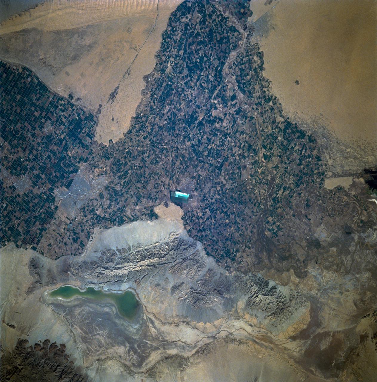
STS060-93-081 (3-11 Feb 1994)--- The Imperial Valley was documented using three films - color visible (seen here), the American infrared film (Kodak Aerochrome 2443), and the Russian panchromatic infrared film (SN-10). Results of this test still await detailed science analysis. However it does appear that good data was acquired of the region, and this data will be complemented by photography acquired by the Mir cosmonauts. In this frame, the U.S.-Mexico border goes from the upper left to the middle right. It is discernible as a vegetation line between Calexico, California and Mexicali, Mexico. The darker vegetation north of that line is due to different agricultural practices, heavier uses of fertilizers and pesticides, and lined (tiled) agricultural fields allowing subterraneean runoff of saline irrigation runoff. South of the line, the more polluted water draining out of the U.S. agricultural areas into the Mexican area has resulted in higher soil salinities and a consequent reduction in agricultural productivity. At the center of the frame, a large settling and desalinization plant has been built to attempt to purify, to some degree, the polluted irrigation waters draining south out of California. The All-American Canal, which brings in water from the Colorado River (off the frame, to the right), is located in the middle right hand portion of the frame. To the upper left is the normally dry Laguna Salada.
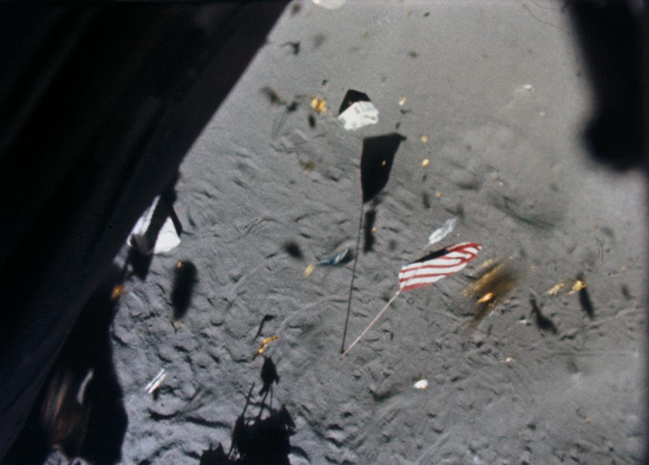
S71-19500 (6 Feb. 1971) --- The Apollo 14 Lunar Module (LM) ascent stage lifts off the lunar surface and the powerful LM engine causes a brief force of wind which scatters gold-colored foil, covering the LM, and disturbs the U.S. flag. This picture was taken from film exposed by the 16mm data acquisition camera - which was mounted inside the LM.
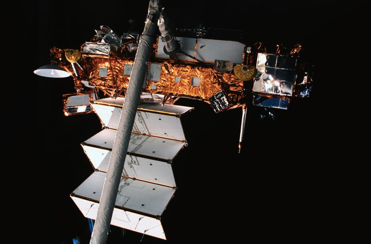
STS048-05-024 (15 Sept 1991) --- The Upper Atmosphere Research Satellite (UARS), in the grasp of the Remote Manipulator System (RMS), was captured on film by a camera aimed through one of the Space Shuttle Discovery's overhead windows. At the time of the photo, deployment of UARS' solar array panel was in progress. A few hours later, the huge satellite was free and on its way to a higher orbit. Data from UARS will enable scientists to study ozone depletion in the stratosphere, or upper atmosphere. The image was photographed with a 35mm camera.
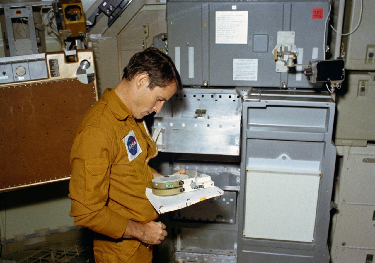
S73-32848 (10 Sept. 1973) --- Scientist-astronaut Edward G. Gibson, science pilot for the third manned Skylab mission (Skylab 4), reads the markings on a magazine of 400 feet of film for the 16mm Data Acquisition Camera (DAC), during a training exercise in the Orbital Workshop (OWS) trainer at Johnson Space Center. Photo credit: NASA
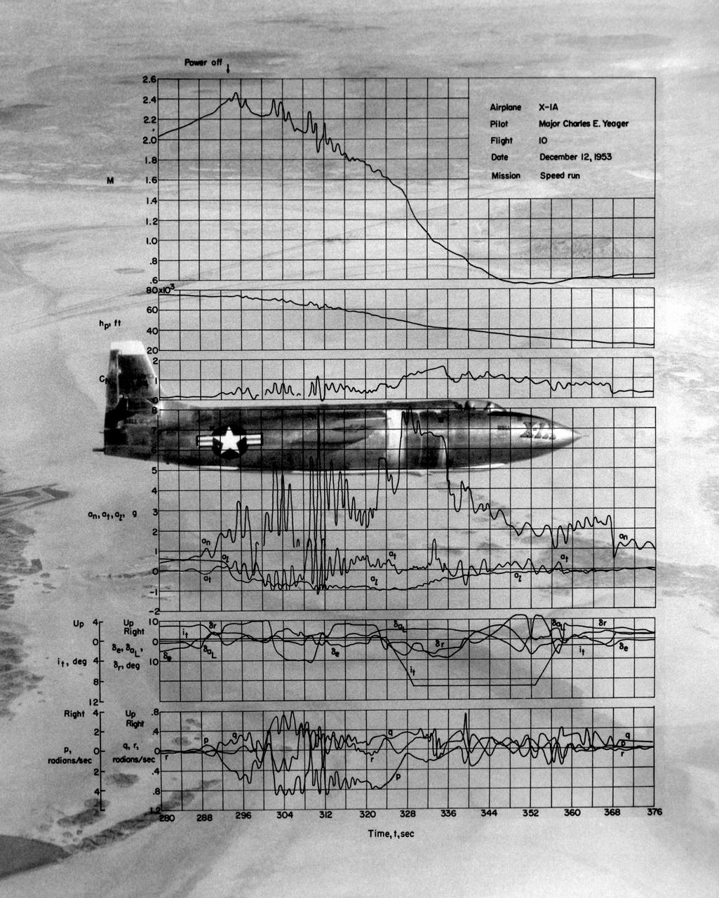
This photo of the X-1A includes graphs of the flight data from Maj. Charles E. Yeager's Mach 2.44 flight on December 12, 1953. (This was only a few days short of the 50th anniversary of the Wright brothers' first powered flight.) After reaching Mach 2.44, then the highest speed ever reached by a piloted aircraft, the X-1A tumbled completely out of control. The motions were so violent that Yeager cracked the plastic canopy with his helmet. He finally recovered from a inverted spin and landed on Rogers Dry Lakebed. Among the data shown are Mach number and altitude (the two top graphs). The speed and altitude changes due to the tumble are visible as jagged lines. The third graph from the bottom shows the G-forces on the airplane. During the tumble, these twice reached 8 Gs or 8 times the normal pull of gravity at sea level. (At these G forces, a 200-pound human would, in effect, weigh 1,600 pounds if a scale were placed under him in the direction of the force vector.) Producing these graphs was a slow, difficult process. The raw data from on-board instrumentation recorded on oscillograph film. Human computers then reduced the data and recorded it on data sheets, correcting for such factors as temperature and instrument errors. They used adding machines or slide rules for their calculations, pocket calculators being 20 years in the future.

An inlet duct lowered into the 20-foot diameter test section of the Altitude Wind Tunnel at the National Advisory Committee for Aeronautics (NACA) Lewis Flight Propulsion Laboratory. Engines and hardware were prepared in the facility’s shop area. The test articles were lifted by a two-rail Shaw box crane through the high-bay and the second-story test chamber before being lowered into the test section. Technicians then spent days or weeks hooking up the supply lines and data recording telemetry. The engines were mounted on wingspans that stretched across the test section. The wingtips attached to the balance frame’s trunnions, which could adjust the angle of attack. The balance frame included six devices that recorded data and controlled the engine. The measurements were visible in banks of manometer boards next to the control room. Photographs recorded the pressure levels in the manometer tubes, and the computing staff manually converted the data into useful measurements. A mechanical pulley system was used to raise and lower the tunnel’s large clamshell lid into place. The lid was sealed into place using hand-turned locks accessible from the viewing platform. The lid had viewing windows above and below the test article, which permitted the filming and visual inspection of the tests.
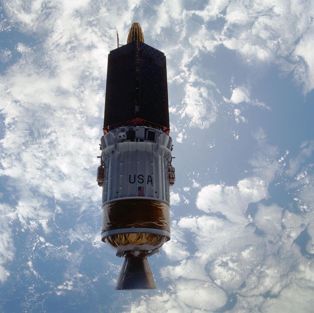
STS043-601-033 (2 Aug 1991) --- The Tracking and Data Relay Satellite (TDRS-E), is seen almost as a silhouette in this 70mm image. The TDRS spacecraft was captured on film as it moved away from the earth-orbiting Atlantis a mere six hours after the shuttle was launched from Pad 39A at Kennedy Space Center, Florida. TDRS, built by TRW, will be placed in a geosynchronous orbit and after on-orbit testing, which requires several weeks, will be designated TDRS-5. The communications satellite will replace TDRS-3 at 174 degrees west longitude. The backbone of NASA's space-to-ground communications, the Tracking and Data Relay Satellites have increased NASA's ability to send and receive data to spacecraft in low-earth orbit to more than 85 percent of the time. Before TDRS, NASA relied solely on a system of ground stations that permitted communications only 15 percent of the time. Increased coverage has allowed on-orbit repairs, live television broadcast from space and continuous dialogues between astronaut crews and ground control during critical periods such as space shuttle landings. The five astronauts of the STS-43 are John E. Blaha, mission commander, Michael a. Baker, pilot, and mission specialists Shannon W. Lucid, G. David Low and James C. Adamson.

SL3-22-0214 (July-September 1973) --- A vertical view of southeastern Washington State as photographed from Earth orbit by one of the six lenses of the Itek-furnished S190-A Multispectral Photographic Facility Experiment aboard the Skylab space station. The Snake River flows into the Columbia River in the most southerly corner of the picture. The Wallula Lake is below the junction of the two rivers. The Yakima Valley is at the southwestern edge of the photograph. The Columbia Basin is in the center of the picture. The Cascade Range extends across the northwest corner of the photograph. This picture was taken with type SO-356 regular color film. The S190-A experiment is part of the Earth Resources Experiments Package. Federal agencies participating with NASA on the EREP project are the Departments of Agriculture, Commerce, Interior, the Environmental Protection Agency and the Corps of Engineers. All EREP photography is available to the public through the Department of Interior?s Earth Resources Observations Systems Data Center, Sioux Falls, South Dakota, 57198. Photo credit: NASA
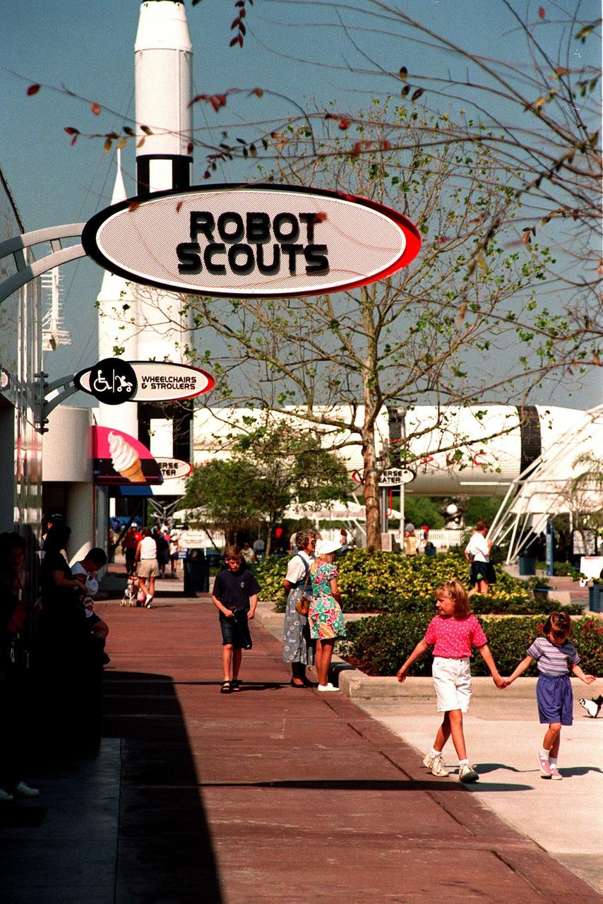
KENNEDY SPACE CENTER, FLA. -- The newly added Robot Scouts exhibit at the KSC Visitor Complex is situated next to the Rocket Garden. Part of the $13 million expansion to the Visitor Complex, the exhibit helps describe for visitors the accomplishments of unsung space heroes space probes and their role in space exploration. It also includes a display of how data from robotic probes might be used to build a human habitat for Mars. Visitors can witness a simulated Martian sunset. Other additions include a new foyer, films, and an International Space Station-themed ticket plaza, featuring a structure of overhanging solar panels and astronauts performing assembly tasks. The KSC Visitor Complex was inaugurated three decades ago and is now one of the top five tourist attractions in Florida. It is located on S.R. 407, east of I-95, within the Merritt Island National Wildlife Refuge

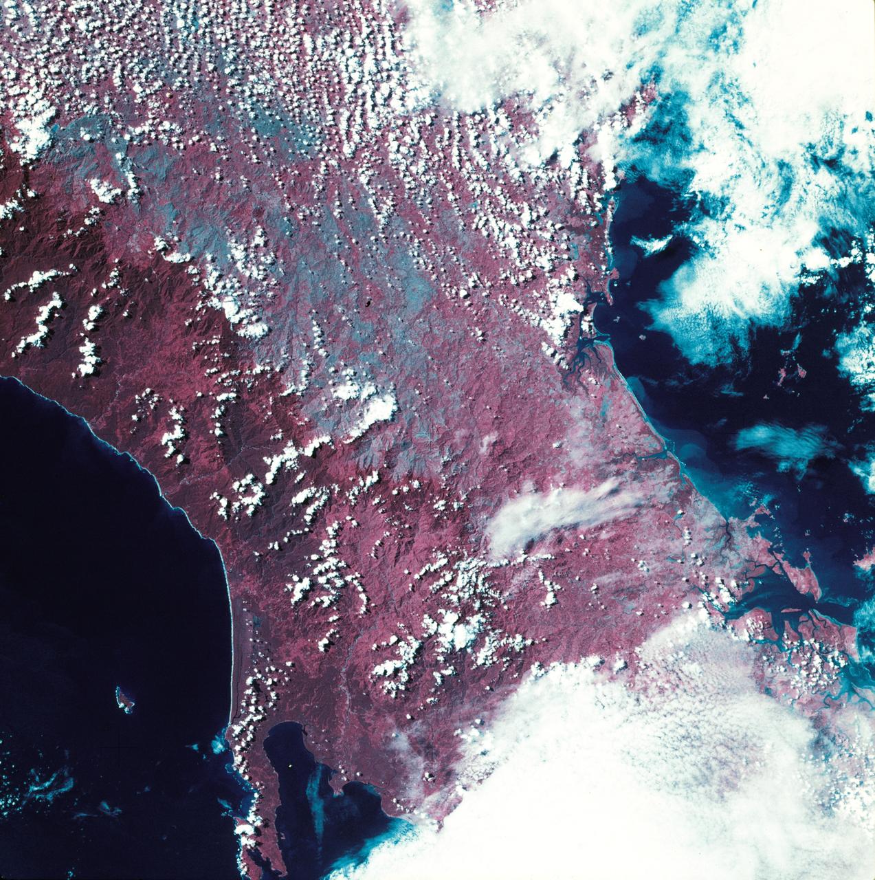
STS093-722-051 (23-27 July 1999) --- The STS-93 astronauts aboard the Space Shuttle Columbia took this picture over the Indian Ocean. The distinctive arrowhead shape of the northern tip of the island of Madagascar is easily recognizable. The land appears red with patches of dark green on the upper slopes. According to NASA scientists studying the STS-93 photo collection, the dark areas are the remnants of forests and the red areas are cleared land. When the photo was taken, the shuttle was flying over a point located at 14.7 degrees south latitude and 44.0 degrees east longitude. Data back information on the 70mm film listed the date and time of the photo as 11:38:20 GMT, July 24, 1999 (Orbit 21).
SL3-27-224 (July-September 1973) --- A vertical view of the western portion of the Republic of Panama on the Isthmus of Panama as photographed from Earth orbit by one of the six lenses of the Itek-furnished S190-A Multispectral Photographic Facility Experiment aboard the Skylab space station. This picture was taken with 2443 infrared color film. The large, clear body of water on the north side of the isthmus is Golfo de los Mosquitos, an extension of the Caribbean Sea. The large, partly cloud-covered body of water on the south side of the isthmus is Golfo de Chiriqui, an extension of the Pacific Ocean. Federal agencies participating with NASA on the EREP project are the Department of Agriculture, Commerce, Interior, the Environmental Protection Agency and the Corps of Engineers. All EREP photography is available to the public through the Department of Interior?s Earth Resources Observation Systems Data Center, Sioux Falls, South Dakota, 57198. Photo credit: NASA
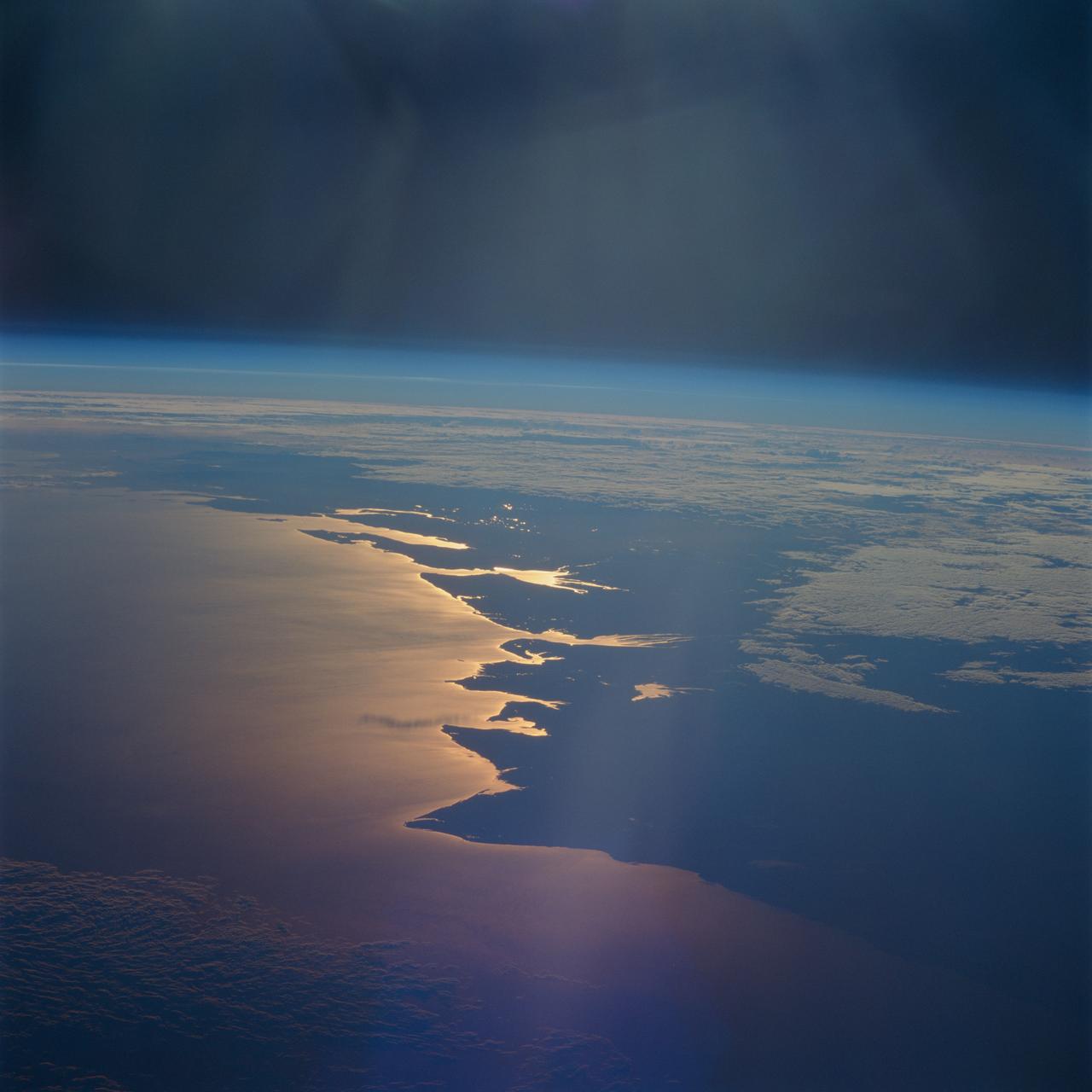
STS093-716-065 (23-27 July 1999) --- The STS-93 astronauts aboard the Space Shuttle Columbia took this picture of a sunrise on the Mozambique Channel along the coast of Madagascar. The nearest point of land is Cape Saint Andre, which forms the northwest corner of the island. Sunglint highlights the land-water boundary along a series of dynamic estuaries. The fifth inlet from the bottom just above the small lake is the Betsiboka Estuary. When the photo was taken, the shuttle was flying over a point located at 18.7 degrees south latitude and 36.1 degrees east longitude. Data back information on the 70mm film listed the time and date as 03:40:43 GMT, July 26, 1999 (orbit 48).
SL2-10-250 (May-June 1973) --- A vertical view of eastern Iowa and northwestern Illinois, as photographed from Skylab space station in Earth orbit. Davenport, Burlington and Muscatine, Iowa; and Rock Island and Moline, Illinois can be delineated on opposite sides of the Mississippi River. The Iowa River and tributaries of it can also be delineated. This photograph was taken with one of six lenses of the Itek-furnished Multispectral Photographic Facility Experiment S190-A mounted in the Multiple Docking Adapter (MDA) of the space station. A six-inch lens, using 70mm medium speed Ektachrome (SO-356) film, was used. Agencies participating with NASA on the EREP project are the Departments of Agriculture, Commerce and Interior; the Environmental Protection Agency and the Corps of Engineers. All EREP photography is available to the public through the Department of Interior's Earth Resources Observations Systems Data Center, Sioux Falls, South Dakota, 57198. Photo credit: NASA
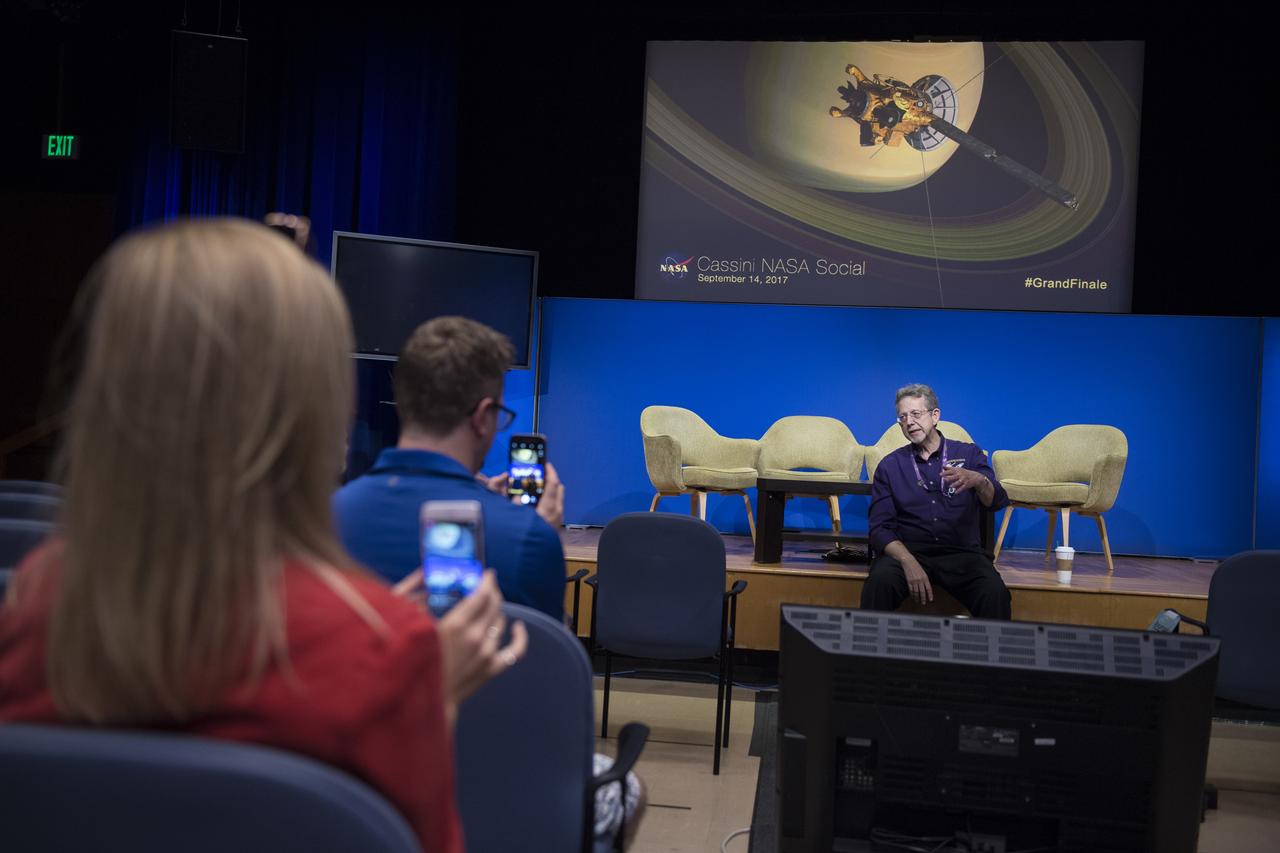
NASA Social attendees film director of NASA's Planetary Science Division, Jim Green as he discusses the Cassini mission, Thursday, Sept. 14, 2017 at NASA's Jet Propulsion Laboratory in Pasadena, California. Since its arrival in 2004, the Cassini-Huygens mission has been a discovery machine, revolutionizing our knowledge of the Saturn system and captivating us with data and images never before obtained with such detail and clarity. On Sept. 15, 2017, operators will deliberately plunge the spacecraft into Saturn, as Cassini gathered science until the end. The “plunge” ensures Saturn’s moons will remain pristine for future exploration. During Cassini’s final days, mission team members from all around the world gathered at NASA’s Jet Propulsion Laboratory, Pasadena, California, to celebrate the achievements of this historic mission. Photo Credit: (NASA/Joel Kowsky)

STS093-709-046 (23-27 July 1999) --- The STS-93 astronauts aboard the Space Shuttle Columbia took this picture featuring the Northern Territory of Australia. Melville Island (bottom) and Bathurst Island are across Clarence Strait just north of the city of Darwin. According to scientists studying the STS-93 photo collection, seasonal fires are common in the region. Winter is the season for agricultural land clearing of the native monsoon forests. Smoke from the fires on the islands is being blown northwest by the prevailing winter winds. Data back information on the 70mm film that recorded this image lists time and date as 05:38:45 GMT, July 25, 1999. When the photo was taken, the shuttle was flying over a point located at 18.4 degrees south latitude and 118.7 east longitude.

KENNEDY SPACE CENTER, FLA. -- Part of the Robot Scouts exhibit in the $13 million expansion to KSC's Visitor Complex, this display offers a view of how data from robotic probes might be used to build a human habitat for Mars. Visitors witness a simulated Martian sunset. Other new additions include and information center, a walk-through Robot Scouts exhibit, a wildlife exhibit, and the film Quest for Life in a new 300-seat theater, plus an International Space Station-themed ticket plaza, featuring a structure of overhanging solar panels and astronauts performing assembly tasks. The KSC Visitor Complex was inaugurated three decades ago and is now one of the top five tourist attractions in Florida. It is located on S.R. 407, east of I-95, within the Merritt Island National Wildlife Refuge
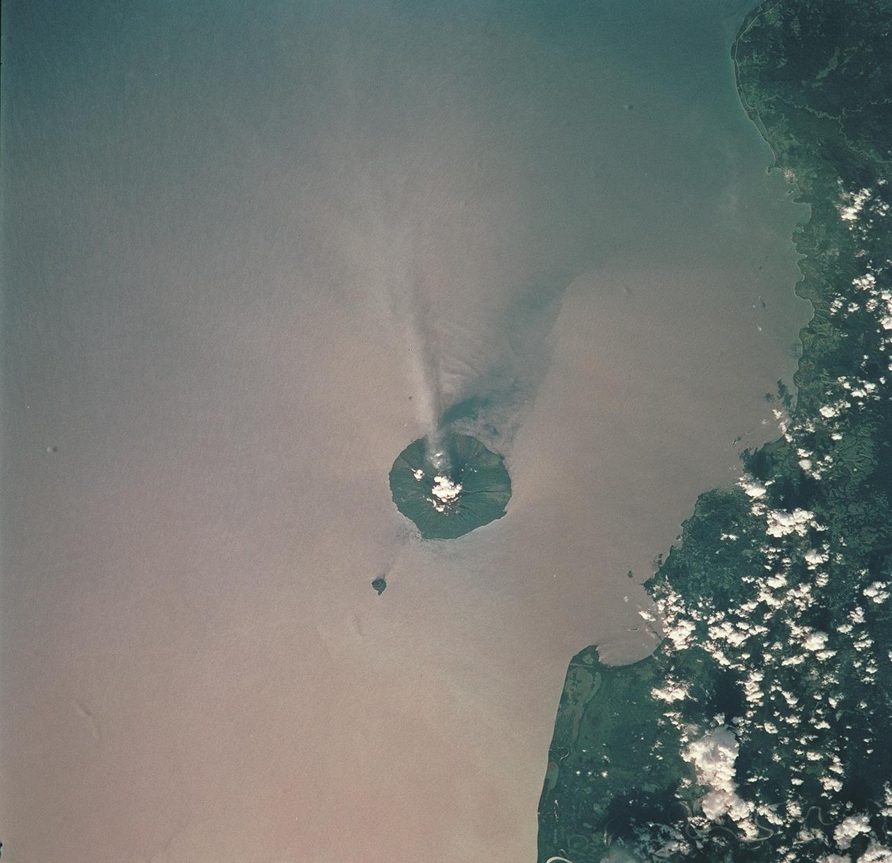
STS093-709-051 (23-27 July 1999) --- The STS-93 astronauts aboard the Space Shuttle Columbia took this picture of the volcanic island of Manam, along the northeast coast of Papua New Guinea. Manam is one in a string of currently active volcanoes called the Bismarck Arc. It is the most active of the group, having begun its present activity in 1994. The plume of steam and ash streaming from its crater extends more than 20 miles into the atmosphere. When the photo was taken, the shuttle was flying over a point located at 12.2 degrees south latitude and 132.0 degrees east longitude. Data back information on the 70mm film lists time and date of the photo as 05:42:31 GMT, July 25, 1999 (orbit 33).
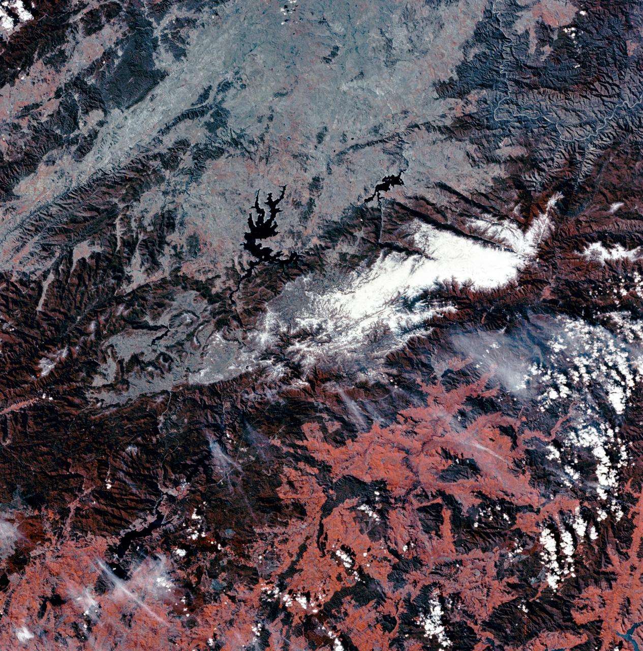
SL3-27-180 (July-September 1973) --- A vertical view of the Snowy Mountains area of Australian Alps in the States of Victoria and New South Wales, Australia, as photographed from Earth orbit by one of the six lenses of the Itek-furnished S190-A Multispectral Photographic Facility Experiment aboard the Skylab space station. This picture was taken with type 2443 infrared color film. The lake near the center of the picture is the Eucumbene Reservoir. This area is located immediately south-southwest of the capital city of Canberra. Federal agencies participating with NASA on the EREP project are the Departments of Agriculture, Commerce, Interior, the Environmental Protection Agency and the Corps of Engineers. All EREP photography is available to the public through the Department of Interior?s Earth Resources Observations Systems Data Center, Sioux Falls, South Dakota, 57198. Photo credit: NASA
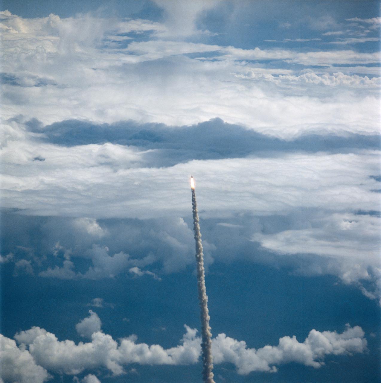
S26-S-026 (29 Sept. 1988) --- The STS-26 launch was captured on film from the NASA Shuttle Training Aircraft, piloted by astronaut Daniel C. Brandenstein, chief of JSC's Astronaut Office. Discovery?s mission was the first flight to be flown after the Challenger accident. The flight crew included astronauts Rick Hauck, commander; Dick Covey, pilot; and three mission specialists, Dave Hilmers, Mike Lounge, and George (Pinky) Nelson. During the four-day mission, the crew deployed the Tracking and Data Relay Satellite (TDRS-C) and operated eleven mid-deck experiments. Discovery completed 64 orbits of the earth before landing at Edwards Air Force Base, California, on October 3, 1988. Photo credit: NASA or National Aeronautics and Space Administration
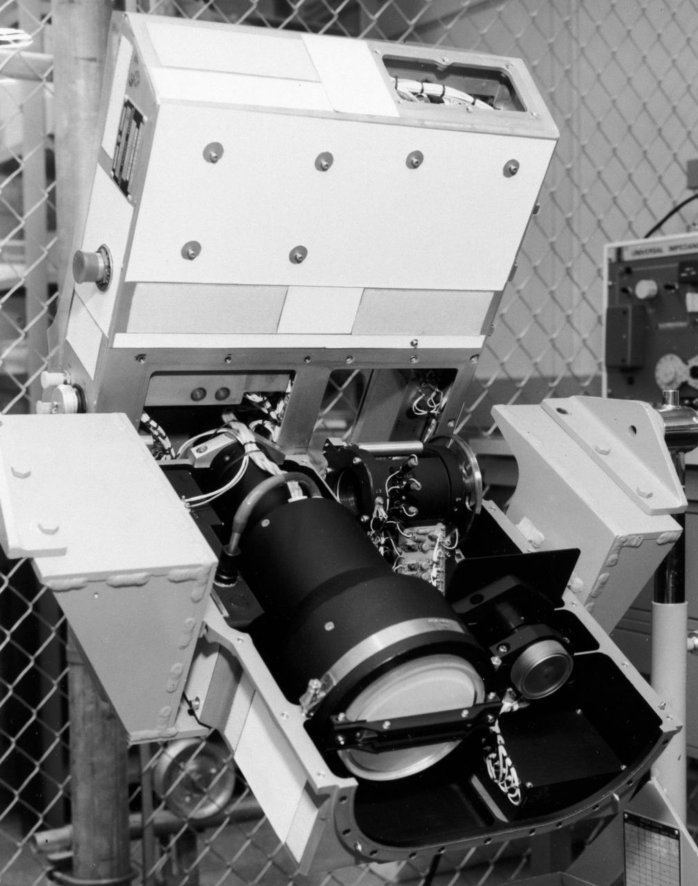
S72-49482 (November 1972) --- The Optical Recorder of the Lunar Sounder Experiment (S-209) which will be mounted in the SIM bay of the Apollo 17 Service Module. The three functional parts of the Lunar Sounder are the optical recorder, the coherent synthetic aperture radar, and the antennas, a retractable dipole for HF and a yagi for VHF. The Lunar Sounder will probe three-quarters of a mile below the moon's surface from the orbiting Apollo 17 spacecraft. Electronic data recorded on film will be retrieved by the crew during trans-Earth EVA. Geologic information on the lunar interior obtained by the sounder will permit scientific investigation of underground rock layers, lava flow patterns, rille (canyon) structures, mascon properties, and any areas containing water. A prototype lunar sounder has been flight tested in aircraft over selected Earth sites to confirm the equipment design and develop scientific analysis techniques. The Lunar Sounder Experiment was developed by North American Rockwell's (NR) Space Division for NASA's Manned Spacecraft Center to provide data for a scientific investigation team with representatives from the Jet Propulsion Laboratory, University of Utah, University of Michigan, U.S. Geological Survey, and NASA Ames Research Center.
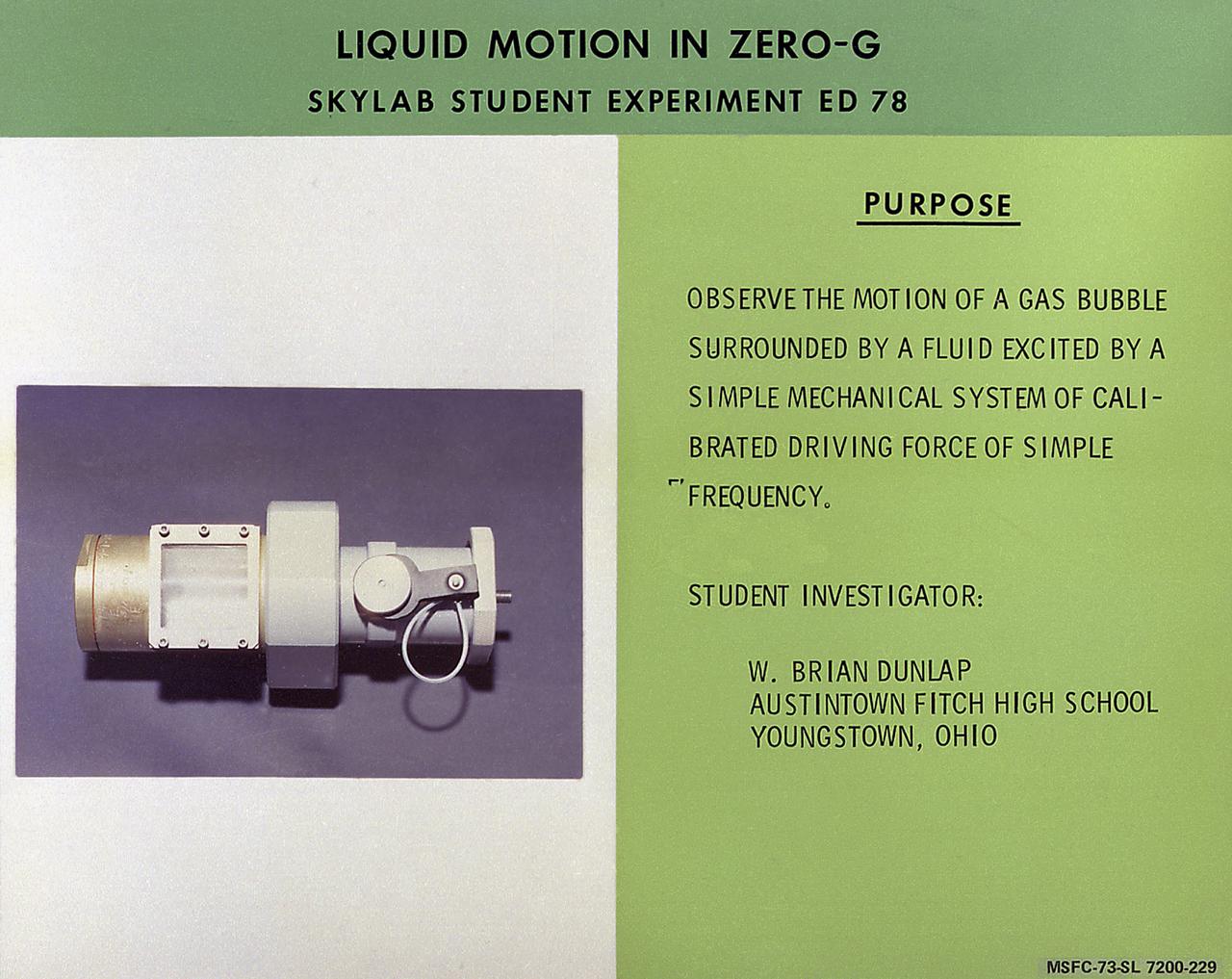
W. Brian Dunlap of Youngstown, Ohio, proposed Skylab student experiment ED-78, Liquid Motion in Zero-G, a study of wave motion in a liquid. He was particularly interested in comparing surface waves over a liquid in zero-gravity with those occurring on Earth. In space, with the absence of gravity, a liquid does not necessarily take the shape of its container as it does on Earth. Adhesion forces may hold the liquid in contact with its container, but the liquid can also assume a free-floating condition. It was in this latter state that Dunlap wished to examine the behavior of surface waves. Data were recorded on videotape and subsequently converted to 16-mm film. Dunlap analyzed these data to determine periods of oscillation of free-floating globules and found agreement with the theory to be much better than expected. In March 1972, NASA and the National Science Teachers Association selected 25 experiment proposals for flight on Skylab. Science advisors from the Marshall Space Flight Center aided and assisted the students in developing the proposals for flight on Skylab.
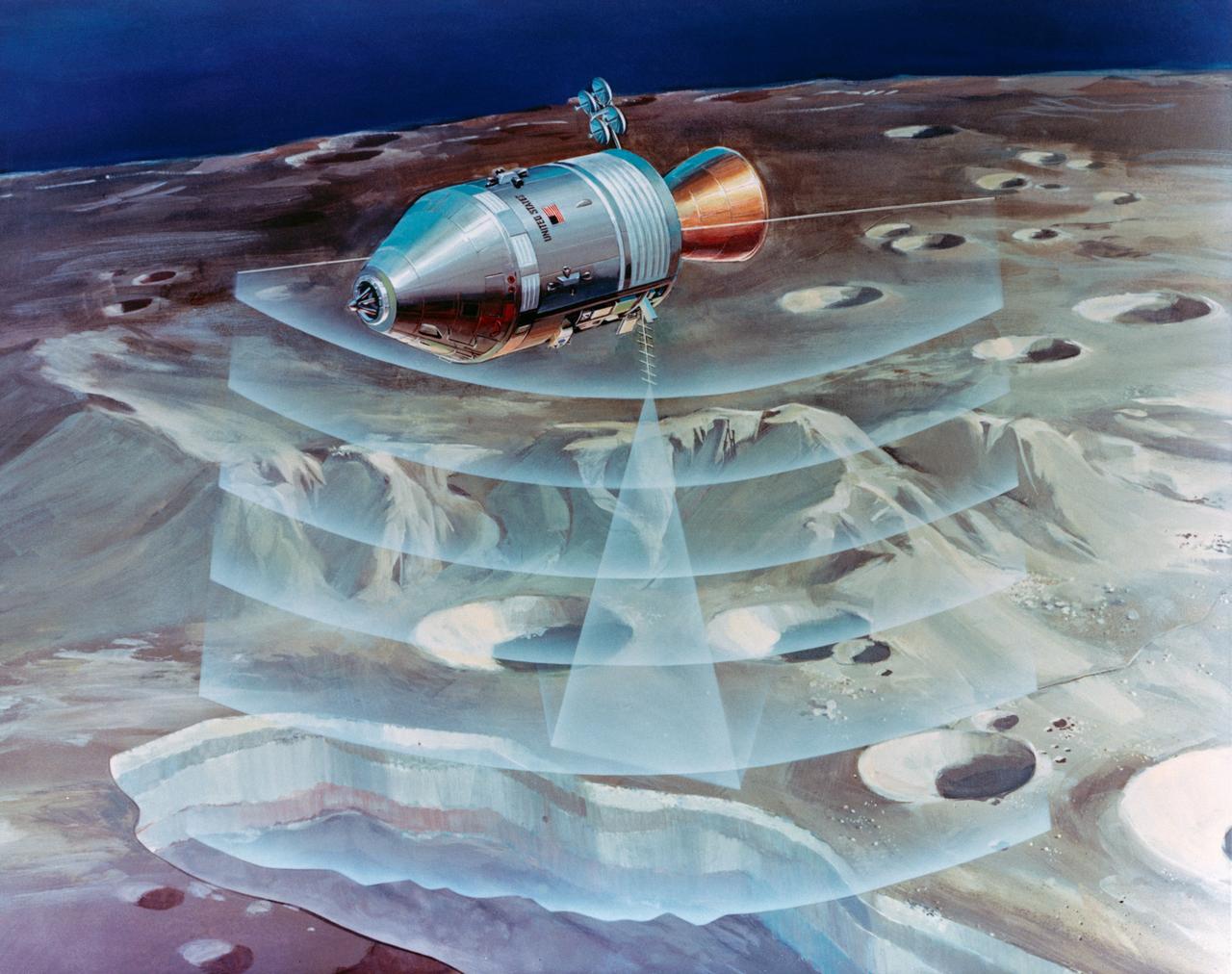
S72-53472 (November 1972) --- An artist's concept illustrating how radar beams of the Apollo 17 lunar sounder experiment will probe three-quarters of a mile below the moon's surface from the orbiting spacecraft. The Lunar Sounder will be mounted in the SIM bay of the Apollo 17 Service Module. Electronic data recorded on film will be retrieved by the crew during trans-Earth EVA. Geologic information on the lunar interior obtained by the sounder will permit scientific investigation of underground rock layers, lava flow patterns, rille (canyon) structures, mascon properties, and any areas containing water. A prototype lunar sounder has been flight tested in aircraft over selected Earth sites to confirm the equipment design and develop scientific analysis techniques. The Lunar Sounder Experiment (S-209) was developed by North American Rockwell's (NR) Space Division for NASA's Manned Spacecraft Center to provide data for a scientific investigation team with representatives from the Jet Propulsion Laboratory, University of Utah, University of Michigan, U.S. Geological Survey, and NASA Ames Research Center.
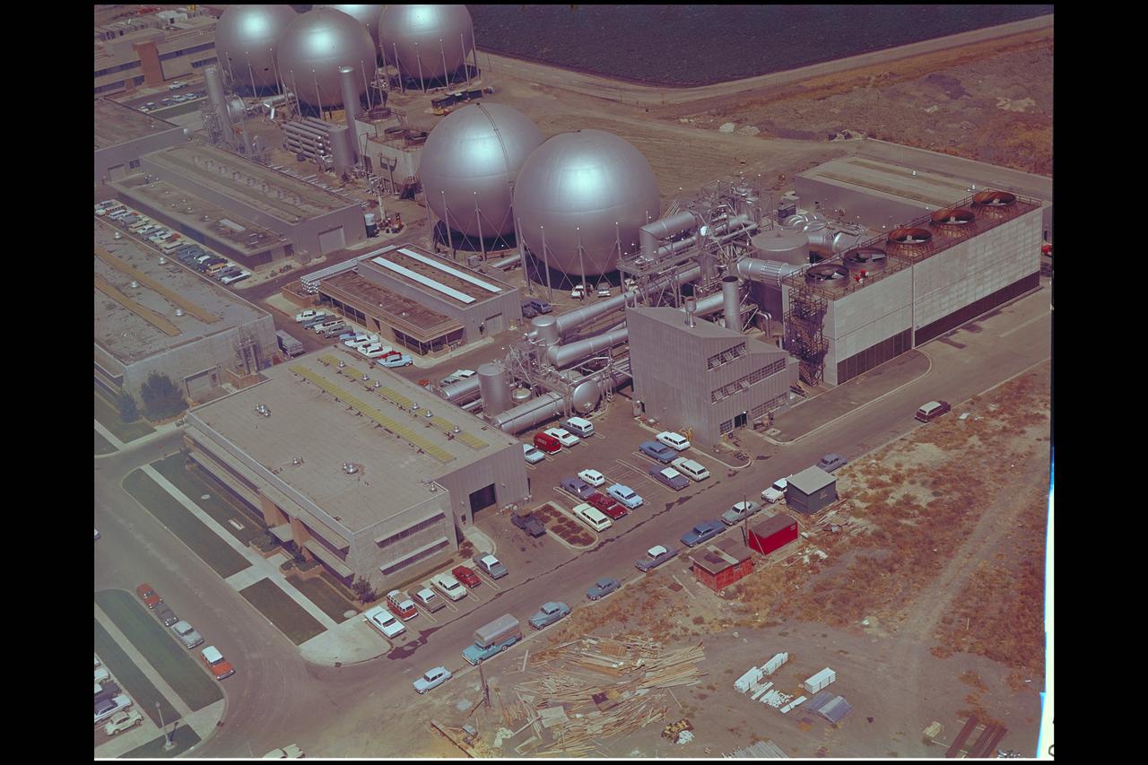
Aerial view of Gasdynamics facility in 1964 and the 20 inch helium tunnel Part of the Thermal Protection Laboratory used to research materials for heat shield applications and for aerodynamic heating and materials studies of vehicles in planetary atmospheres. This laboratory is comprised of five separate facilities: an Aerodynamic Heating Tunnel, a Heat Transfer Tunnel, two Supersonic Turbulent Ducts, and a High-Power CO2 Gasdynamic Laser. All these facilities are driven by arc-heaters, with the exception of the large, combustion-type laser. The arc-heated facilities are powered by a 20 Megawatt DC power supply. Their effluent gas stream (test gases; Air, N2, He, CO2 and mixtures; flow rates from 0.05 to 5.0 lbs/sec) discharges into a five-stage stream-ejector-driven vacuum system. The vacuum system and power supply are common to the test faciities in building N-238. All of the facilities have high pressure water available at flow rates up to 4, 000 gals/min. The data obtained from these facilities are recorded on magnetic tape or oscillographs. All forms of data can be handled whether from thermo-couples, pressure cells, pyrometers, or radiometers, etc. in addition, closed circuit T. V. monitors and various film cameras are available. (operational since 1962)
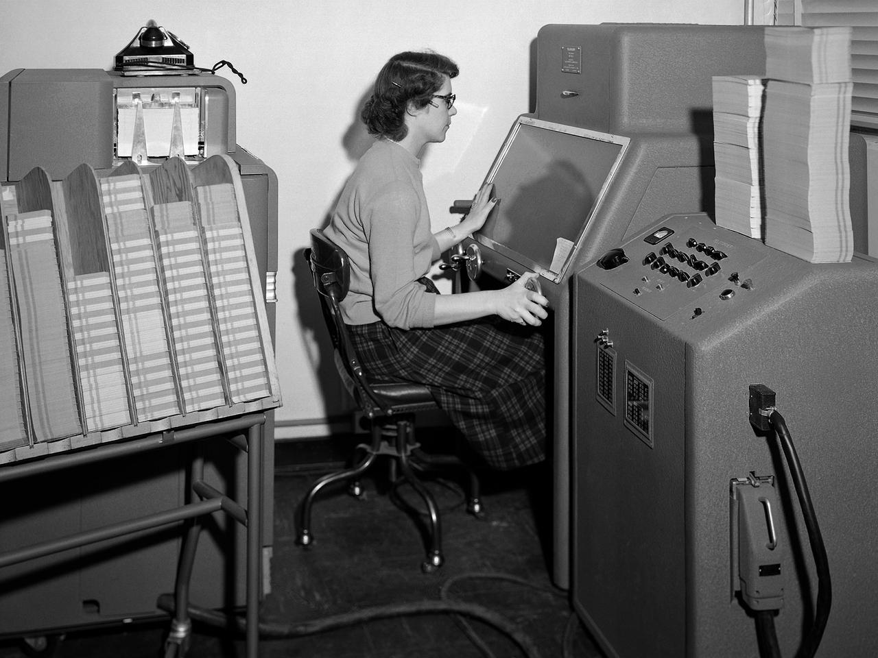
A staff member from the Computing Section at the National Advisory Committee for Aeronautics (NACA) Lewis Flight Propulsion Laboratory operates an International Business Machines (IBM) telereader at the 8- by 6-Foot Supersonic Wind Tunnel. The telereader was used to measure recorded data from motion picture film or oscillographs. The machine could perform 50 measurements per minute. The component to her right is a telerecordex that was used convert the telereader measurements into decimal form and record the data on computer punch cards. During test runs in the 8- by 6-foot tunnel, or the other large test facilities, pressure sensors on the test article were connected to mercury-filled manometer tubes located below the test section. The mercury would rise or fall in relation to the pressure fluctuations in the test section. Initially, female staff members, known as “computers,” transcribed all the measurements by hand. The process became automated with the introduction of the telereader and other data reduction equipment in the early 1950s. The Computer Section staff members were still needed to operate the machines. The Computing Section was introduced during World War II to relieve short-handed research engineers of some of the tedious work. The computers made the initial computations and plotted the data graphically. The researcher then analyzed the data and either summarized the findings in a report or made modifications or ran the test again. The computers and analysts were located in the Altitude Wind Tunnel Shop and Office Building office wing during the 1940s. They were transferred to the new facility when the 8- by 6-Foot tunnel began operations in 1948.

S99-E-5555 (17 February 2000) --- As photographed from the Space Shuttle Endeavour, this oblique electronic still image of Earth's horizon reveals a great deal of cloud cover. In the case of the electronic still camera (ESC), as well as film-bearing instruments, clouds naturally obscure views of recognizable land masses. Much of Earth is heavily cloud covered during the current mission and meteorlogists and oceanographers are interested in studying that aspect. However, the Shuttle Radar Topography Mission's other sensing equipment, X-SAR and C-band antennae, are able to penetrate cloud cover and record important topographic data for mapmakers and scientists of other disciplines. In addition to the sensing equipment mentioned above, this mission is supporting the EarthKAM project which utilizes the services of another electronic still camera mounted in Endeavour's windows. Unlike this oblique view, EarthKAM records strictly vertical or nadir imagery of points all over the world. Students across the United States and in France, Germany and Japan are taking photos throughout the STS-99 mission. And they are using these new photos, plus all the images already available in the EarthKAM system, to enhance their classroom learning in Earth and space science, social studies, geography, mathematics and more.
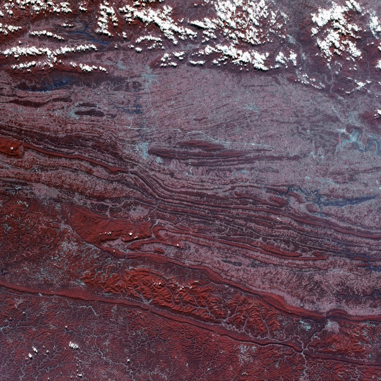
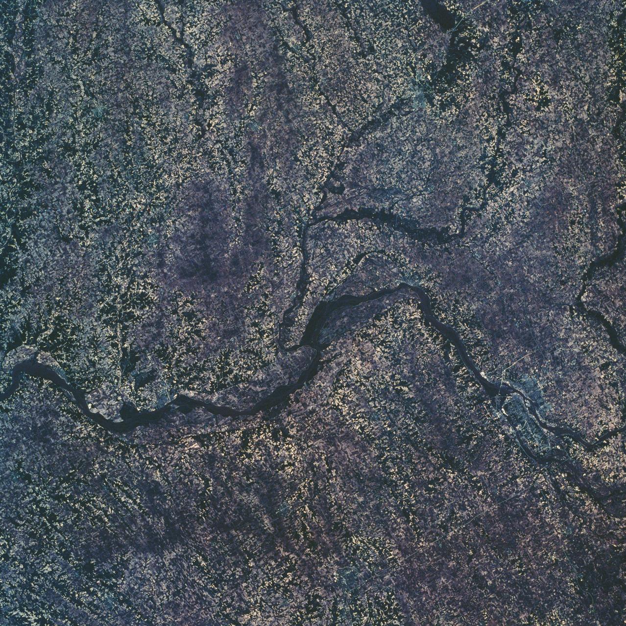
SL3-45-020 (July-September 1973) --- A vertical view of the Virginia-Tennessee-Kentucky border area as photographed from Earth orbit by one of the six lenses of the Itek-furnished S190-A Multispectral Photographic Facility Experiment aboard the Skylab space station. This picture was taken with type 2443 infrared color film. The S190-A experiment is part of the Skylab Earth Resources Experiments Package. The long, narrow ridge is Pine Mountain; and it is crossed by U.S. 25E at Pineville near its southernmost end. Some 25 miles south of Pineville U.S. 25E passes through the famed Cumberland Gap which at 1,600 feet elevation crosses Cumberland Mountain. Kingsport, Tennessee is located east of Cumberland Gap near the center of the picture. Bristol, Tennessee-Virginia is further east. Greenville and Elizabethton, Tennessee can also be seen in this photograph. The clouds across the southeast edge of the picture are over the Blue Ridge Mountains. Federal agencies participating with NASA on the EREP project are the Departments of Agriculture, Commerce, Interior, the Environmental Protection Agency and the Corps of Engineers. All EREP photography is available to the public through the Department of Interior?s Earth Resources Observations Systems Data Center, Sioux Falls, 57198. Photo credit: NASA
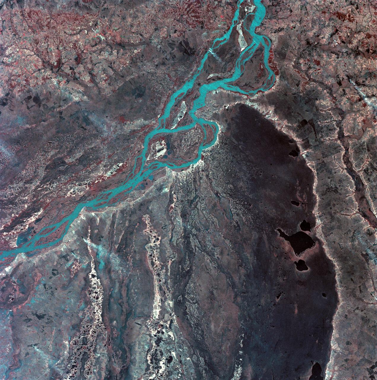
SL3-33-167 (July-September 1973) --- A vertical view of the Argentina-Paraguay border area of South America as photographed from Earth orbit by one of the six lenses of the Itek-furnished S190-A Multispectral Photographic Facility Experiment aboard the Skylab space station. This picture was taken with type 2443 infrared color film. The Parana River flows from east to west across the picture. This part of the Rio Parana is located between the towns of Posadas, Argentina, and Resistencia, Argentina. The major body of water in the large swamp area is Laguna Ibera. Note the several fires burning in this area. The largest land mass (Argentina) is south of the river. Paraguay is north of the river. Isla Apipe Grande is near the center of the photograph. The S190-A experiment is part of the Skylab Earth Resources Experiments Package. Federal agencies participating with NASA on the EREP project are the Departments of Agriculture, Commerce, Interior, the Environmental Protection Agency and the Corps of Engineers. All EREP photography is available to the public through the Department of Interior?s Earth Resources Observations Systems Data Center, Sioux Falls, South Dakota, 57198. Photo credit: NASA
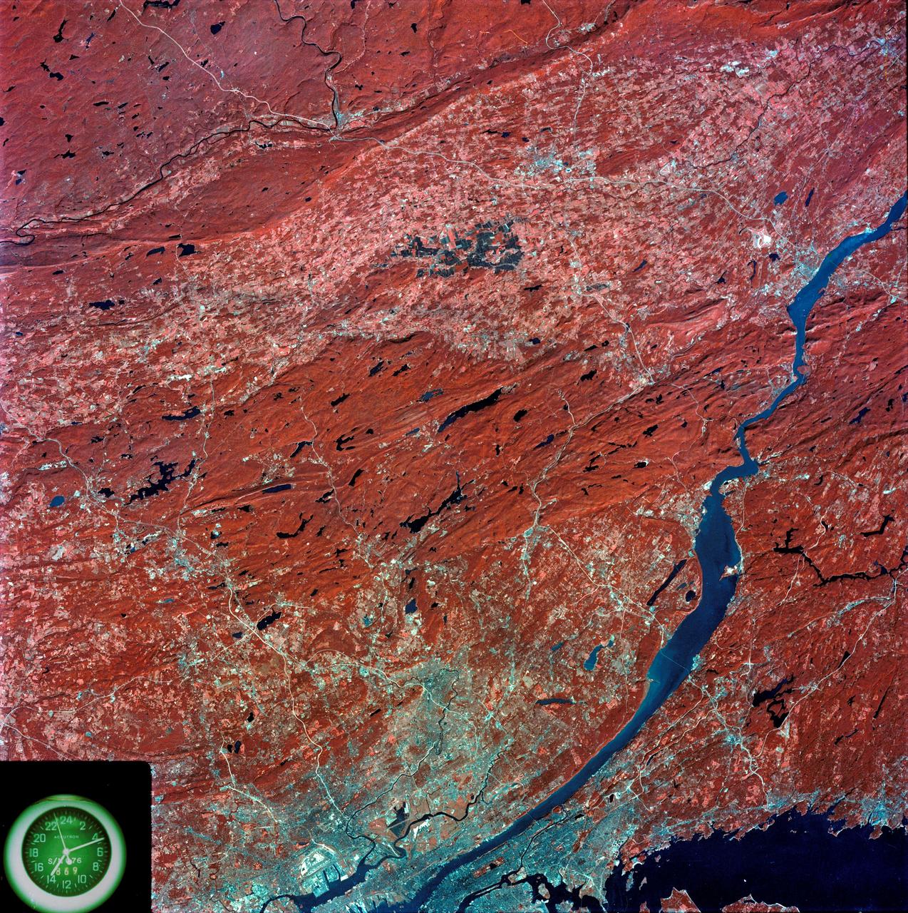
SL3-87-299 (July-September 1973) --- A vertical view of southeastern New York State is seen in this Skylab 3 Earth Resources Experiments Package S190-B (five-inch Earth terrain camera) infrared photograph taken from the Skylab space station in Earth orbit. An 18-inch, 450mm lens and type 2443 infrared Ektachrome film was used. This picture covers the northern part of New Jersey, a part of northwestern Pennsylvania, and the western tip of Connecticut. The body of water is Long Island Sound. The wide Hudson River flows southward across a corner of the photograph. The New York City metropolitan area occupies part of the picture. Federal agencies participating with NASA on the EREP project are the Departments of Agriculture, Commerce, Interior, the Environmental Protection Agency and the Corps of Engineers. All EREP photography is available to the public through the Department of Interior?s Earth Resources Observations Systems Data Center, Sioux Falls, South Dakota, 57198. Photo credit: NASA
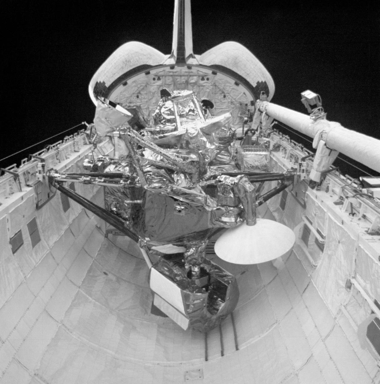
S48-E-013 (15 Sept 1991) --- The Upper Atmosphere Research Satellite (UARS) in the payload bay of the earth- orbiting Discovery. UARS is scheduled for deploy on flight day three of the STS-48 mission. Data from UARS will enable scientists to study ozone depletion in the stratosphere, or upper atmosphere. This image was transmitted by the Electronic Still Camera (ESC), Development Test Objective (DTO) 648. The ESC is making its initial appearance on a Space Shuttle flight. Electronic still photography is a new technology that enables a camera to electronically capture and digitize an image with resolution approaching film quality. The digital image is stored on removable hard disks or small optical disks, and can be converted to a format suitable for downlink transmission or enhanced using image processing software. The Electronic Still Camera (ESC) was developed by the Man- Systems Division at the Johnson Space Center and is the first model in a planned evolutionary development leading to a family of high-resolution digital imaging devices. H. Don Yeates, JSC's Man-Systems Division, is program manager for the ESC. THIS IS A SECOND GENERATION PRINT MADE FROM AN ELECTRONICALLY PRODUCED NEGATIVE.
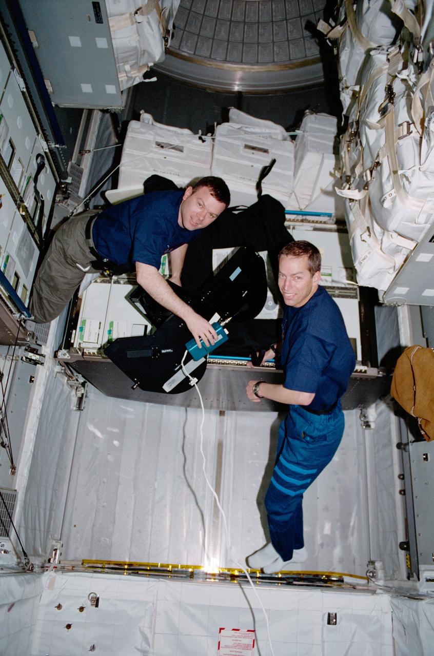
Pilot James M. Kelly (left) and Commander James D. Wetherbee for the STS-102 mission, participate in the movement of supplies inside Leonardo, the Italian Space Agency built Multipurpose Logistics Module (MPLM). In this particular photograph, the two are handling a film magazine for the IMAX cargo bay camera. The primary cargo of the STS-102 mission, the Leonardo MPLM is the first of three such pressurized modules that will serve as the International Space Station's (ISS') moving vans, carrying laboratory racks filled with equipment, experiments, and supplies to and from the Station aboard the Space Shuttle. The cylindrical module is approximately 21-feet long and 15- feet in diameter, weighing almost 4.5 tons. It can carry up to 10 tons of cargo in 16 standard Space Station equipment racks. Of the 16 racks the module can carry, 5 can be furnished with power, data, and fluid to support refrigerators or freezers. In order to function as an attached station module as well as a cargo transport, the logistics module also includes components that provide life support, fire detection and suppression, electrical distribution, and computer functions. The eighth station assembly flight, the STS-102 mission also served as a crew rotation flight. It delivered the Expedition Two crew to the Station and returned the Expedition One crew back to Earth.
STS070-386-027 (13-22 JULY 1995) --- High-speed film provided this close-up view of the Space Shuttle Discovery’s aft, featuring the ignition of one of the primary thrusters. Note the impact of the firing on the starboard side of the vertical stabilizer. Crew members told a August 11, 1995, gathering of Johnson Space Center (JSC) employees that the Window Experiment (WINDEX) paid close attention to surface glow, jet plumes, water dumps, aurora and airglow. The data collection is part of an effort to avoid misinterpretation of measurements of Earth, the solar system and starts taken from satellites in low Earth-orbits and prevent damage to sensitive systems and solar arrays during rendezvous and docking. Such firings of the thrusters increase local densities of gases in the atmosphere dramatically and introduce non-natural elements that react with the atmosphere dramatically and spacecraft systems enveloped by the thruster plume. WINDEX recorded phenomena associated with thruster start-up and shut-down transients and observed the effect of the transients on Shuttle glow phenomenon.

SL3-33-156 (July-September 1973) --- A near vertical view of the Florence, Italy area as photographed from Earth orbit by one of the Itek-furnished S190-A Multispectral Photographic Facility Experiment aboard the Skylab space station. The view extends from the Ligurian Sea, an extension of the Mediterranean Sea, across the Apennine Mountains to the Po River Valley. Florence (Firenze) is near the center of the land mass. The mouth of the Arno River is at the center of the coastline. The city of Leghorn (Livorno) is on the coast just south of the Arno River. This picture was taken with type 2443 infrared color film. The S190-A experiment is part of the Skylab Earth Resources Experiments Package. Federal agencies participating with NASA on the EREP project are the Department of Agriculture, Commerce, Interior, the Environmental Protection Agency and the Corps of Engineers. All EREP photography is available to the public through the Department of Interior?s Earth Resources Observations Systems Data Center, Sioux Falls, South Dakota, 57198. Photo credit: NASA
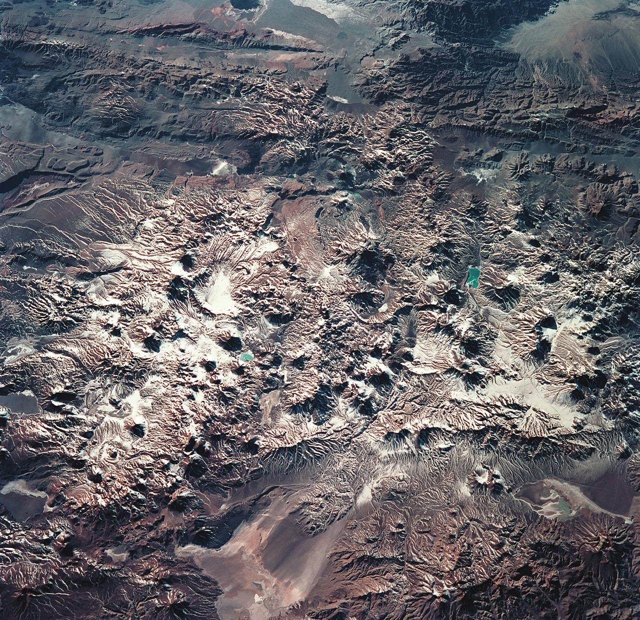
STS093-715-006 (23-27 July 1999) --- The STS-93 astronauts aboard the Space Shuttle Columbia took this picture featuring the early morning sun highlighting Laguna Verde and the High Andes of the Atacama Province of Chile and the Catamarca Province of Argentina. The jewel-like Laguna Verde (center left) sits amid apparent east-west lines of volcanic peaks that average 19,000 feet (5791 meters) elevation. At the upper right are darker mountains of folded and thrusted rocks. The light colored areas at the bottom are Salar de Perdenales (left) and Salar de Maricunga (right). Salars, which are common in the Andes, are salty lakebeds that are usually dry. The prevailing wind direction (out of the west) is clearly discernible at the edges of the salars. When this photo was taken, the shuttle was flying over a point located at 25.2 degrees south latitude and 70.4 degrees west longitude. Data back information on the 70mm film lists the time and date of the photo as 12:46:31 GMT, July 25, 1999 (orbit 38).
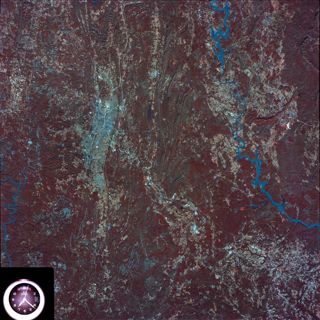
SL4-93-153 (February 1974) --- A vertical view of the Birmingham and central Alabama area is seen in this Skylab 4 Earth Resources Experiments Package S190-B (five-inch earth terrain camera) infrared photographed taken from the Skylab space station in Earth orbit. Illustrated here is the utility of color infrared film in depicting distribution of living vegetation in the 3,600 square mile Birmingham region. The Birmingham industrial complex, with a population of nearly 850,000, is the light gray area nestled in the valley between the northeast-trending ridges that are prominent topographic features in the southern Appalachian Mountains. The narrow ridges and adjacent valleys reflect folded and faulted sedimentary rocks, indicating the complex geological history of the region. Two major rivers and several reservoirs are easily distinguished in this photograph. Bankhand Lake, formed by a dam on the Black Warrior River, appears as bright blue west of Birmingham. Two lakes are formed by dams on the Goosa River east of Birmingham. Federal and state highways appear as thin white lines and are easily identified. Interstate 65 to Montgomery is the prominent white line extending southward from Birmingham. Power line clearings are visible in the center of the picture along the Goosa River, and can be traced northwestward to northern parts of Birmingham. The predominant deep red color of the picture is due to the reflections from living vegetation. In contrast are the light tan areas that commonly occur as rectangular patterns in the east part of the photograph and represent mature agricultural crops or grazing lands. Analysis of the photographic data from the earth terrain camera will be conducted by Dr. H. Jayroe of the Marshall Space Flight Center in developing analytical techniques. All EREP photography is available to the public through the Department of Interior's Earth Resources Observations Systems Data Center, Sioux Falls, South Dakota, 57198. Photo credit: NASA
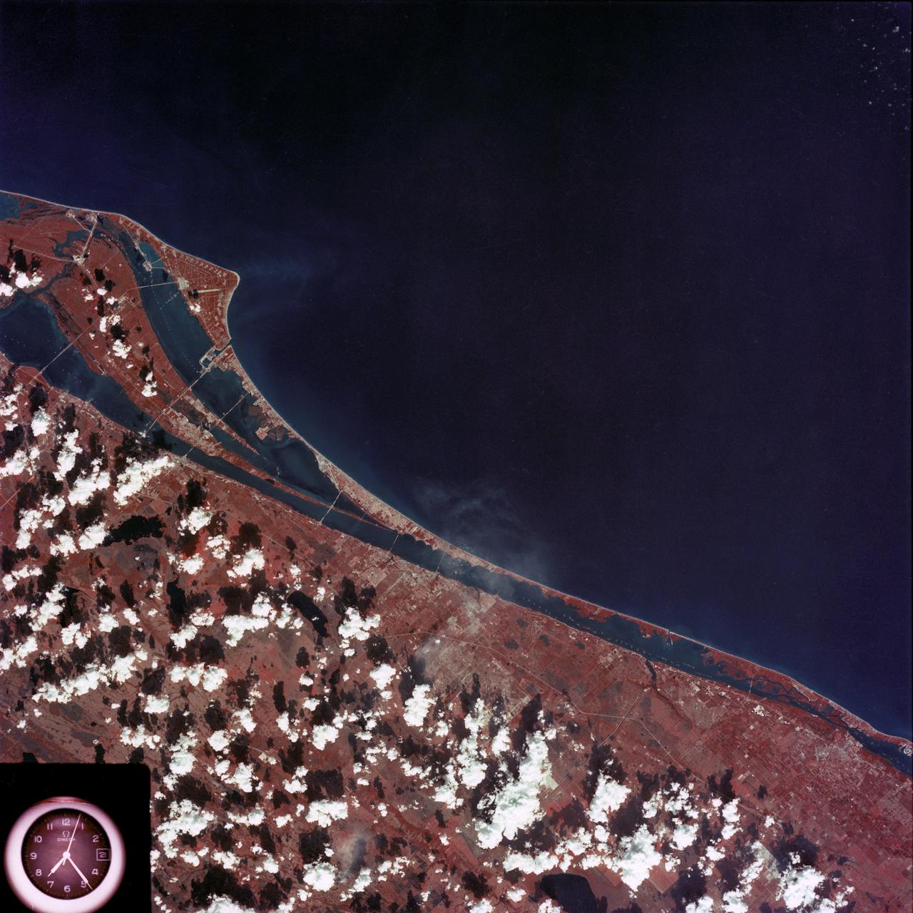
SL4-93-167 (February 1974) --- A vertical view of the Kennedy Space Center and the Florida Atlantic coast area is seen in this Skylab 4 Earth Resources Experiments Package S190-B (five-inch earth terrain camera) infrared photography taken from the Skylab space station in Earth orbit. This photograph shows the major land-ocean features of the Florida coast near Vero Beach northward to Cape Canaveral and the KSC complex. The launch pads for the Skylab missions are clearly visible. Identification of living vegetation is possible through the use of the color infrared film. Various shades of red portray differences in the vegetation such as shown in the patterns in the agricultural area near Vero Beach. In the Kennedy Space Center, the nearly continuous and uniform red color shows that most of the land areas are heavily vegetated. The white coastal beach areas are strongly contrasted to the red land and the blue Atlantic Ocean. Old dunal areas in KSC are visible on Merritt Island which is separated from the Launch areas by the Banana River and the mainland by the Indian River. Federal and state highways and numerous causeways over the rivers are easily identified. The Florida mainland is partly shadowed by small white clouds which cast a pronounced shadow to the east of each cloud indicated the Sun is west of solar noon. Federal agencies participating with NASA on the EREP project are the Departments of Agriculture, Commerce, Interior, the Environmental Protection Agency and the Core of Engineers. All EREP photography is available to the public through the Department of Interior's Earth Resources Observations Systems Data Center, Sioux Falls, South Dakota, 57198. Photo credit: NASA
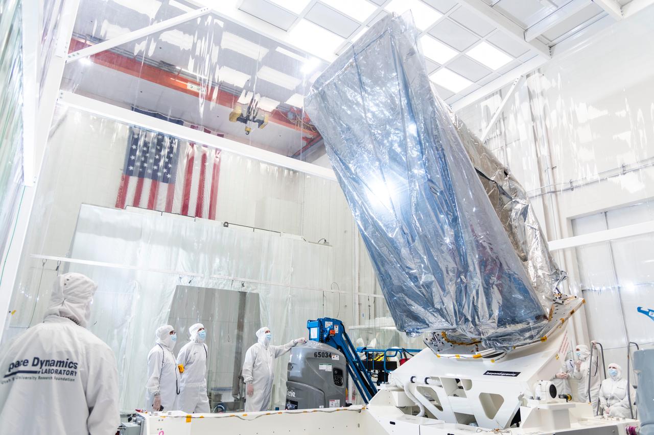
The instrument enclosure for NASA's Near-Earth Object (NEO) Surveyor on May 22, 2025, is seen in a clean room at the Space Dynamics Laboratory (SDL) in Logan, Utah, shortly after arriving from the agency's Jet Propulsion Laboratory in Southern California, where it was assembled. The instrument enclosure is attached to an articulating assembly dolly and wrapped in silver-colored material (composed of a metalized polyester film and a low charging polyethylene laminate) to protect the flight hardware from static electricity and dust particles during transport. The instrument enclosure will house the observatory's scientific instrument, which includes a three-reflection aluminum telescope, state-of-the-art infrared detectors, and an innovative passive cooling system to keep the instrument at cryogenic temperatures. The telescope, which has an aperture of nearly 20 inches (50 centimeters), features detectors sensitive to two infrared wavelengths in which near-Earth objects re-radiate solar heat. The instrument enclosure is designed to ensure heat produced by the spacecraft and instrument during operations doesn't interfere with its infrared observations. As NASA's first space-based detection mission specifically designed for planetary defense, NEO Surveyor will seek out, measure, and characterize the hardest-to-find asteroids and comets that might pose a hazard to Earth. While many near-Earth objects don't reflect much visible light, they glow brightly in infrared light due to heating by the Sun. Targeting launch in late 2027, the NEO Surveyor mission is led by Professor Amy Mainzer at UCLA for NASA's Planetary Defense Coordination Office and is being managed by JPL for the Planetary Missions Program Office at NASA's Marshall Space Flight Center in Huntsville, Alabama. BAE Systems, SDL, and are among the companies that were contracted to build the spacecraft and its instrumentation. The Laboratory for Atmospheric and Space Physics at the University of Colorado Boulder will support operations, and IPAC at Caltech in Pasadena, California, is responsible for producing some of the mission's data products. Caltech manages JPL for NASA. https://photojournal.jpl.nasa.gov/catalog/PIA26589
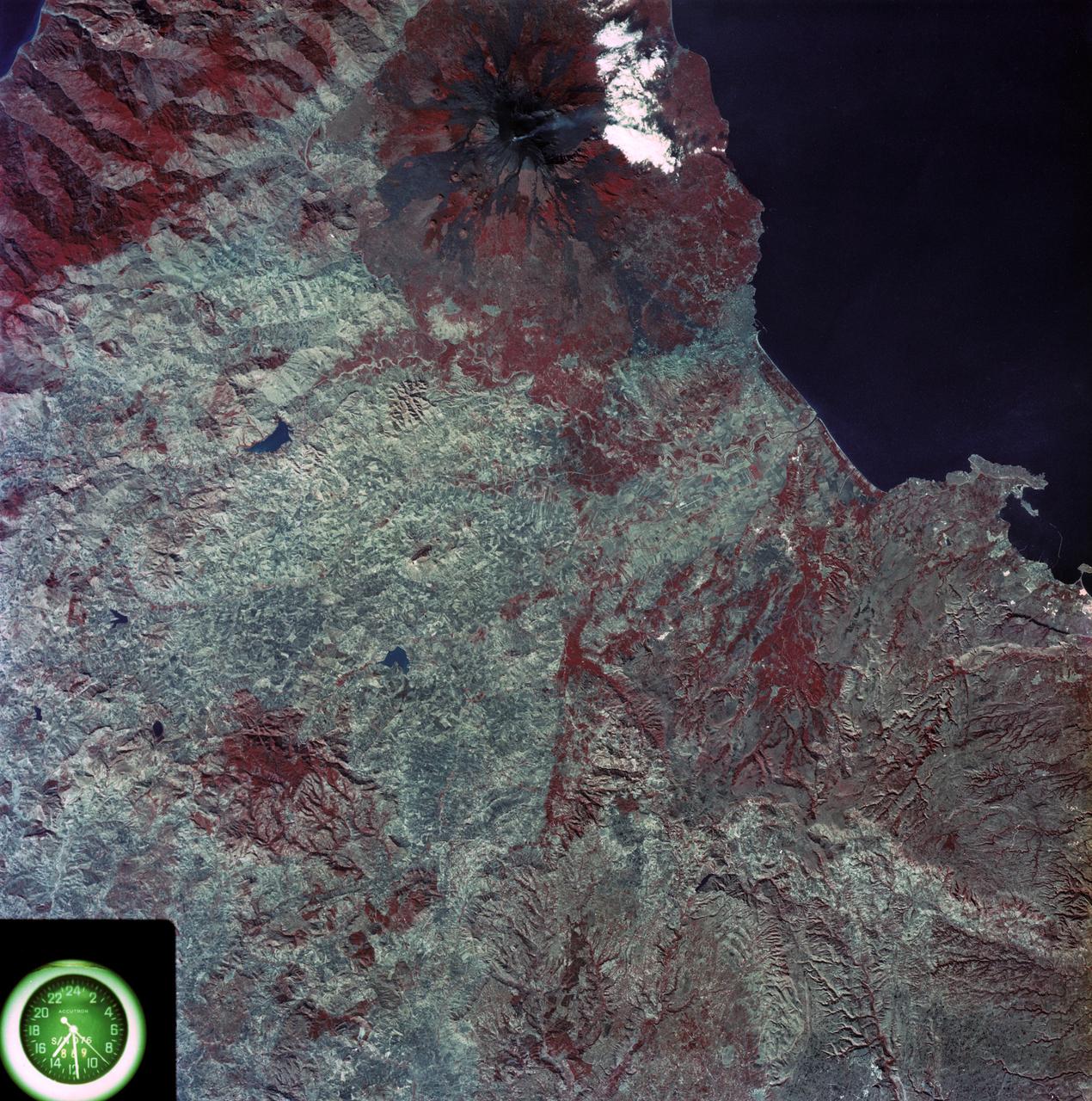
SL3-87-355 (July-September 1973) --- A vertical view of the eastern coast of Sicily area is seen in this Skylab 3 Earth Resources Experiments Package S190-B (five-inch earth terrain camera) infrared photograph taken from the Skylab space station in Earth orbit. Mount Etna, the highest volcano in Europe (10,958 feet), is still active as evidenced by the thin plume of smoke emanating from its crest. (The altitude is approximate because the height of the volcano changes with each eruption). On the flanks of Etna recent lava flows appear black in contrast to the older flows and volcanic debris that are red. Numerous small, circular cinder cones on the flanks represent sites of previous eruptions. Catania, on the Mediterranean coast south of Etna, is the largest of several cities and villages which appear as light-gray patches on the lower slopes of the volcano. Plano de Catania, south of the city of Catania, is outlined by polygonal light and dark agricultural tracts. Several lakes, the largest of which is Lake Pozzillo, show up as dark blue in the photograph. The unusual colors in the picture are due to the use of color infrared film in which vegetation appears red. This is very evident on the slopes of Etna, in the Monti Nebrodi area at upper let, and in the local areas in the lower part of the picture. Studies of Mount Etna and related volcanic features will be undertaken by Professor Roberto Cassinis of Servizio Geologio d?Italia, Rome. Federal agencies participating with NASA on the EREP project are the Departments of Agriculture, Commerce, Interior, the Environmental Protection Agency and the Corps of Engineers. All EREP photography is available to the public through the Department of Interior?s Earth Resources Observation Systems Data Center, Sioux Falls, South Dakota, 57198. Photo credit: NASA

This image depicts a vast canyon of dust and gas in the Orion Nebula from a 3-D computer model based on observations by NASA's Hubble Space Telescope and created by science visualization specialists at the Space Telescope Science Institute (STScI) in Baltimore, Md. A 3-D visualization of this model takes viewers on an amazing four-minute voyage through the 15-light-year-wide canyon. Credit: NASA, G. Bacon, L. Frattare, Z. Levay, and F. Summers (STScI/AURA) Go here to learn more about Hubble 3D: <a href="http://www.nasa.gov/topics/universe/features/hubble_imax_premiere.html" rel="nofollow">www.nasa.gov/topics/universe/features/hubble_imax_premier...</a> or <a href="http://www.imax.com/hubble/" rel="nofollow">www.imax.com/hubble/</a> Take an exhilarating ride through the Orion Nebula, a vast star-making factory 1,500 light-years away. Swoop through Orion's giant canyon of gas and dust. Fly past behemoth stars whose brilliant light illuminates and energizes the entire cloudy region. Zoom by dusty tadpole-shaped objects that are fledgling solar systems. This virtual space journey isn't the latest video game but one of several groundbreaking astronomy visualizations created by specialists at the Space Telescope Science Institute (STScI) in Baltimore, the science operations center for NASA's Hubble Space Telescope. The cinematic space odysseys are part of the new Imax film "Hubble 3D," which opens today at select Imax theaters worldwide. The 43-minute movie chronicles the 20-year life of Hubble and includes highlights from the May 2009 servicing mission to the Earth-orbiting observatory, with footage taken by the astronauts. The giant-screen film showcases some of Hubble's breathtaking iconic pictures, such as the Eagle Nebula's "Pillars of Creation," as well as stunning views taken by the newly installed Wide Field Camera 3. While Hubble pictures of celestial objects are awe-inspiring, they are flat 2-D photographs. For this film, those 2-D images have been converted into 3-D environments, giving the audience the impression they are space travelers taking a tour of Hubble's most popular targets. "A large-format movie is a truly immersive experience," says Frank Summers, an STScI astronomer and science visualization specialist who led the team that developed the movie visualizations. The team labored for nine months, working on four visualization sequences that comprise about 12 minutes of the movie. "Seeing these Hubble images in 3-D, you feel like you are flying through space and not just looking at picture postcards," Summers continued. "The spacescapes are all based on Hubble images and data, though some artistic license is necessary to produce the full depth of field needed for 3-D." The most ambitious sequence is a four-minute voyage through the Orion Nebula's gas-and-dust canyon, about 15 light-years across. During the ride, viewers will see bright and dark, gaseous clouds; thousands of stars, including a grouping of bright, hefty stars called the Trapezium; and embryonic planetary systems. The tour ends with a detailed look at a young circumstellar disk, which is much like the structure from which our solar system formed 4.5 billion years ago. Based on a Hubble image of Orion released in 2006, the visualization was a collaborative effort between science visualization specialists at STScI, including Greg Bacon, who sculpted the Orion Nebula digital model, with input from STScI astronomer Massimo Roberto; the National Center for Supercomputing Applications at the University of Illinois at Urbana-Champaign; and the Spitzer Science Center at the California Institute of Technology in Pasadena. For some of the sequences, STScI imaging specialists developed new techniques for transforming the 2-D Hubble images into 3-D. STScI image processing specialists Lisa Frattare and Zolt Levay, for example, created methods of splitting a giant gaseous pillar in the Carina Nebula into multiple layers to produce a 3-D effect, giving the structure depth. The Carina Nebula is a nursery for baby stars. Frattare painstakingly removed the thousands of stars in the image so that Levay could separate the gaseous layers on the isolated Carina pillar. Frattare then replaced the stars into both foreground and background layers to complete the 3-D model. For added effect, the same separation was done for both visible and infrared Hubble images, allowing the film to cross-fade between wavelength views in 3-D. In another sequence viewers fly into a field of 170,000 stars in the giant star cluster Omega Centauri. STScI astronomer Jay Anderson used his stellar database to create a synthetic star field in 3-D that matches recent razor-sharp Hubble photos. The film's final four-minute sequence takes viewers on a voyage from our Milky Way Galaxy past many of Hubble's best galaxy shots and deep into space. Some 15,000 galaxies from Hubble's deepest surveys stretch billions of light-years across the universe in a 3-D sequence created by STScI astronomers and visualizers. The view dissolves into a cobweb that traces the universe's large-scale structure, the backbone from which galaxies were born. In addition to creating visualizations, STScI's education group also provided guidance on the "Hubble 3D" Educator Guide, which includes standards-based lesson plans and activities about Hubble and its mission. Students will use the guide before or after seeing the movie. "The guide will enhance the movie experience for students and extend the movie into classrooms," says Bonnie Eisenhamer, STScI's Hubble Formal Education manager. The Hubble Space Telescope is a project of international cooperation between NASA and the European Space Agency (ESA) and is managed by NASA’s Goddard Space Flight Center (GSFC) in Greenbelt, Md. The Space Telescope Science Institute (STScI) conducts Hubble science operations. The institute is operated for NASA by the Association of Universities for Research in Astronomy, Inc., Washington, D.C.
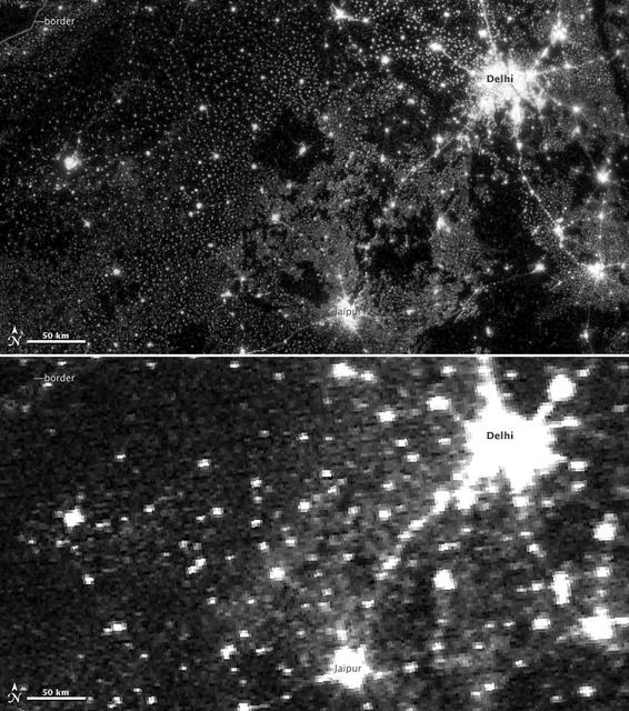
NASA image acquired November 11-12, 2012. On November 12, 2012, the Visible Infrared Imaging Radiometer Suite (VIIRS) on the Suomi NPP satellite captured the top nighttime image of city, village, and highway lights near Delhi, India. For comparison, the lower image shows the same area one night earlier, as observed by the Operational Line Scan (OLS) system on a Defense Meteorological Satellite Program (DMSP) spacecraft. Since the 1960s, the U.S. Air Force has operated DMSP in order to observe clouds and other weather variables in key wavelengths of infrared and visible light. Since 1972, the DMSP satellites have included the Operational Linescan System (OLS), which gives weather forecasters some ability to see in the dark. It has been a highly successful sensor, but it is dependent on older technology with lower resolution than most scientists would like. And for many years, DMSP data were classified. Through improved optics and “smart” sensing technology, the VIIRS “day-night band,” is ten to fifteen times better than the OLS system at resolving the relatively dim lights of human settlements and reflected moonlight. Each VIIRS pixel shows roughly 740 meters (0.46 miles) across, compared to the 3-kilometer footprint (1.86 miles) of DMSP. Beyond the resolution, the new sensor can detect dimmer light sources. And since the VIIRS measurements are fully calibrated (unlike DMSP), scientists now have the precision required to make quantitative measurements of clouds and other features. “In contrast to the Operational Line Scan system, the imagery from the new day-night band is almost like a nearsighted person putting on glasses for the first time and looking at the Earth anew,” says Steve Miller, an atmospheric scientist at Colorado State University. “VIIRS has allowed us to bring this coarse, blurry view of night lights into clearer focus. Now we can see things in such great detail and at such high precision that we’re really talking about a new kind of measurement.” Unlike a film camera that captures a photograph in one exposure, VIIRS produces an image by repeatedly scanning a scene and resolving it as millions of individual picture elements, or pixels. The day-night band goes a step further, determining on-the-fly whether to use its low, medium, or high-gain mode. If a pixel is very bright, a low-gain mode on the sensor prevents the pixel from over-saturating. If the pixel is dark, the signal will be amplified. “On a hand-held camera, there’s a nighttime setting where the shutter will stay open much longer than it would under daylight imaging conditions,” says Chris Elvidge, who leads the Earth Observation Group at NOAA’s National Geophysical Data Center. “The day-night band is similar. It increases the exposure time—the amount of time that it’s collecting photons for pixels.” NASA Earth Observatory image by Jesse Allen and Robert Simmon, using Suomi NPP VIIRS and DMSP OLS data provided courtesy of Chris Elvidge (NOAA National Geophysical Data Center). Suomi NPP is the result of a partnership between NASA, NOAA, and the Department of Defense. Caption by Mike Carlowicz. Instrument: Suomi NPP - VIIRS Credit: <b><a href="http://www.earthobservatory.nasa.gov/" rel="nofollow"> NASA Earth Observatory</a></b> <b>Click here to view all of the <a href="http://earthobservatory.nasa.gov/Features/NightLights/" rel="nofollow"> Earth at Night 2012 images </a></b> <b>Click here to <a href="http://earthobservatory.nasa.gov/NaturalHazards/view.php?id=79846" rel="nofollow"> read more </a> about this image </b> <b><a href="http://www.nasa.gov/audience/formedia/features/MP_Photo_Guidelines.html" rel="nofollow">NASA image use policy.</a></b> <b><a href="http://www.nasa.gov/centers/goddard/home/index.html" rel="nofollow">NASA Goddard Space Flight Center</a></b> enables NASA’s mission through four scientific endeavors: Earth Science, Heliophysics, Solar System Exploration, and Astrophysics. Goddard plays a leading role in NASA’s accomplishments by contributing compelling scientific

NASA image acquired July 27, 2001 In southwestern Jordan lies an unusual landscape. Mountains of granite and sandstone rise next to valleys filled with red sand. Some of the mountains reach a height of about 1,700 meters (5,600 feet) above sea level, and many have near-vertical slopes. So alien is this landscape, it’s nicknamed “Valley of the Moon,” and it has served as the film set for a movie about Mars. Yet nomadic people have lived here for thousands of years. Declared a protected area in 1998, this unearthly landscape is Wadi Rum. The Advanced Land Imager (ALI) on NASA’s Earth Observing-1 (EO-1) satellite captured this natural-color image on July 27, 2001. The scene includes part of Wadi Rum and an adjacent area to the east. East of the protected area, fields with center-pivot irrigation make circles of green and brown (image upper right). As the earth tones throughout the image attest, the area is naturally arid, receiving little annual precipitation and supporting only sparse vegetation. Between rocky peaks, the sandy valleys range in color from beige to brick. Ancient granite rocks dating from the Precambrian underlie younger rocks, and some of these basement rocks have eroded into rugged, steep-sloped mountains. The granite mountains have risen thanks partly to crisscrossing fault lines under the park. Overlying the granite are sandstones from the Cambrian and Ordovician Periods, as well as loose sands. Lawrence of Arabia, who fought in the Arab Revolt of 1917–1918, made frequent references to Wadi Rum in his book The Seven Pillars of Wisdom. Likewise, a prominent feature of the protected area is named after the book. Several popular sites in Wadi Rum bear Lawrence of Arabia’s name, but whether he actually visited those sites is uncertain. To download the full high res go to: <a href="http://earthobservatory.nasa.gov/IOTD/view.php?id=49945" rel="nofollow">earthobservatory.nasa.gov/IOTD/view.php?id=49945</a> NASA Earth Observatory image created by Jesse Allen and Robert Simmon, using EO-1 ALI data provided courtesy of the NASA EO-1 team and the United States Geological Survey. Caption by Michon Scott. Instrument: EO-1 - ALI Credit: <b><a href="http://www.earthobservatory.nasa.gov/" rel="nofollow"> NASA Earth Observatory</a></b> <b><a href="http://www.nasa.gov/centers/goddard/home/index.html" rel="nofollow">NASA Goddard Space Flight Center</a></b> enables NASA’s mission through four scientific endeavors: Earth Science, Heliophysics, Solar System Exploration, and Astrophysics. Goddard plays a leading role in NASA’s accomplishments by contributing compelling scientific knowledge to advance the Agency’s mission. <b>Follow us on <a href="http://twitter.com/NASA_GoddardPix" rel="nofollow">Twitter</a></b> <b>Join us on <a href="http://www.facebook.com/pages/Greenbelt-MD/NASA-Goddard/395013845897?ref=tsd" rel="nofollow">Facebook</a></b>
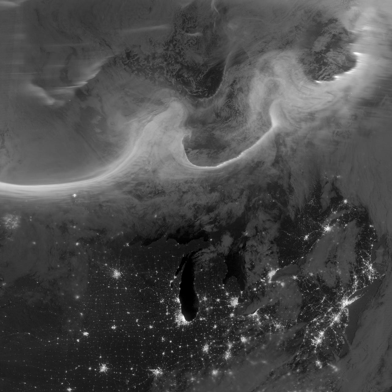
Overnight on October 4-5, 2012, a mass of energetic particles from the atmosphere of the Sun were flung out into space, a phenomenon known as a coronal mass ejection. Three days later, the storm from the Sun stirred up the magnetic field around Earth and produced gorgeous displays of northern lights. NASA satellites track such storms from their origin to their crossing of interplanetary space to their arrival in the atmosphere of Earth. Using the “day-night band” (DNB) of the Visible Infrared Imaging Radiometer Suite (VIIRS), the Suomi National Polar-orbiting Partnership (Suomi NPP) satellite acquired this view of the aurora borealis early on the morning of October 8, 2012. The northern lights stretch across Canada’s Quebec and Ontario provinces in the image, and are part of the auroral oval that expanded to middle latitudes because of a geomagnetic storm. The DNB sensor detects dim light signals such as auroras, airglow, gas flares, city lights, and reflected moonlight. In the case of the image above, the sensor detected the visible light emissions as energetic particles rained down from Earth’s magnetosphere and into the gases of the upper atmosphere. The images are similar to those collected by the Operational Linescan System flown on U.S. Defense Meteorological Satellite Program (DMSP) satellites for the past three decades. “When I first saw images like this as a graduate student, I was immediately struck by the fluid dynamic characteristics of the aurora,” said Tom Moore, a space physicist at NASA's Goddard Space Flight Center. “Viewing the aurora in this way makes it immediately clear that space weather is an interaction of fluids from the Sun with those of the Earth's upper atmosphere. The electrodynamics make for important differences between plasmas and ordinary fluids, but familiar behaviors (for example, waves and vortices) are still very apparent. It makes me wonder at the ability of apparently empty space to behave like a fluid.” Auroras typically occur when solar flares and coronal mass ejections—or even an active solar wind stream—disturb and distort the magnetosphere, the cocoon of space protected by Earth’s magnetic field. The collision of solar particles and pressure into our planet’s magnetosphere accelerates particles trapped in the space around Earth (such as in the radiation belts). Those particles are sent crashing down into Earth’s upper atmosphere—at altitudes of 100 to 400 kilometers (60 to 250 miles)—where they excite oxygen and nitrogen molecules and release photons of light. The results are rays, sheets, and curtains of dancing light in the sky. Auroras are a beautiful expression of the connection between Sun and Earth, but not all of the connections are benign. Auroras are connected to geomagnetic storms, which can distort radio communications (particularly high frequencies), disrupt electric power systems on the ground, and give slight but detectable doses of radiation to flight crews and passengers on high-latitude airplane flights and on spacecraft. The advantage of images like those from VIIRS and DMSP is resolution, according to space physicist Patrick Newell of the Johns Hopkins University Applied Physics Laboratory. “You can see very fine detail in the aurora because of the low altitude and the high resolution of the camera,” he said. Most aurora scientists prefer to use images from missions dedicated to aurora studies (such as Polar, IMAGE, and ground-based imagers), which can offer many more images of a storm (rather than one per orbit) and can allow researchers to calculate the energy moving through the atmosphere. There are no science satellites flying right now that provide such a view, though astronauts regularly photograph and film auroras from the International Space Station. NASA Earth Observatory image by Jesse Allen and Robert Simmon, using VIIRS Day-Night Band data from the Suomi National Polar-orbiting Partnership (Suomi NPP) and the University of Wisconsin's Community Satellite Processing Package. Suomi NPP is the result of a partnership between NASA, the National Oceanic and Atmospheric Administration, and the Department of Defense. Caption by Mike Carlowicz. Instrument: Suomi NPP - VIIRS Credit: <b><a href="http://www.earthobservatory.nasa.gov/" rel="nofollow"> NASA Earth Observatory</a></b> <b><a href="http://www.nasa.gov/audience/formedia/features/MP_Photo_Guidelines.html" rel="nofollow">NASA image use policy.</a></b> <b><a href="http://www.nasa.gov/centers/goddard/home/index.html" rel="nofollow">NASA Goddard Space Flight Center</a></b> enables NASA’s mission through four scientific endeavors: Earth Science, Heliophysics, Solar System Exploration, and Astrophysics. Goddard plays a leading role in NASA’s accomplishments by contributing compelling scientific knowledge to advance the Agency’s mission. <b>Follow us on <a href="http://twitter.com/NASA_GoddardPix" rel="nofollow">Twitter</a></b> <b>Like us on <a href="http://www.facebook.com/pages/Greenbelt-MD/NASA-Goddard/395013845897?ref=tsd" rel="nofollow">Facebook</a></b> <b>Find us on <a href="http://instagrid.me/nasagoddard/?vm=grid" rel="nofollow">Instagram</a></b>