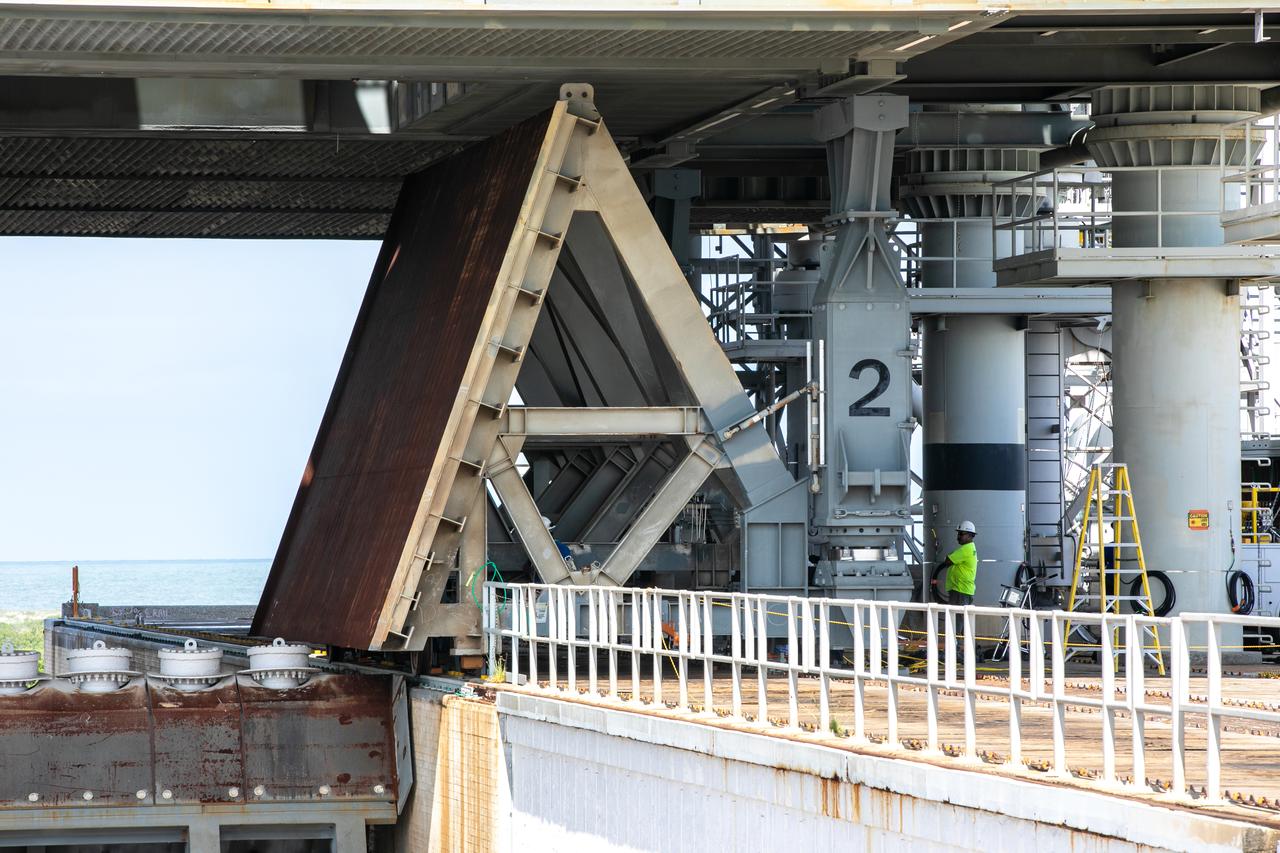
At Launch Pad 39B at NASA's Kennedy Space Center in Florida, construction workers assist as a large segment of the support hardware for a new flame deflector is positioned in the flame trench. The new flame deflector will be positioned about six feet south of the shuttle-era flame deflector’s position. During liftoff of NASA’s Space Launch System, the rocket’s flame and energy will be diverted to the north side of the flame trench. The north side of the deflector will be protected by a NASA standard coating. The south side of the deflector will not be slanted and will have no lining. The new design will provide easier access for inspection, maintenance and repair. The Ground Systems Development and Operations (GSDO) Program at Kennedy is managing the installation of the flame deflector for Exploration Mission 1, deep space missions, and NASA's Journey to Mars.
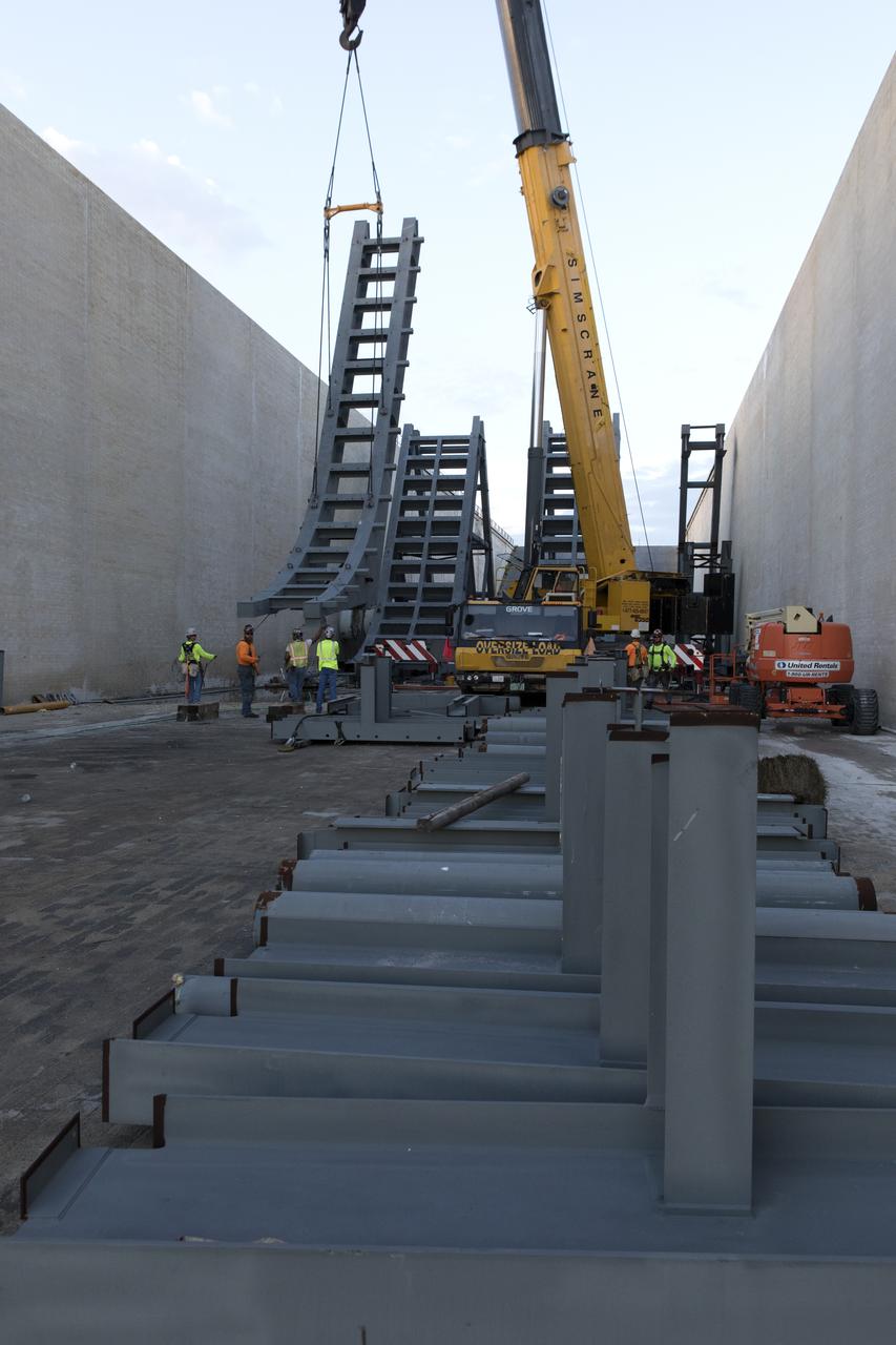
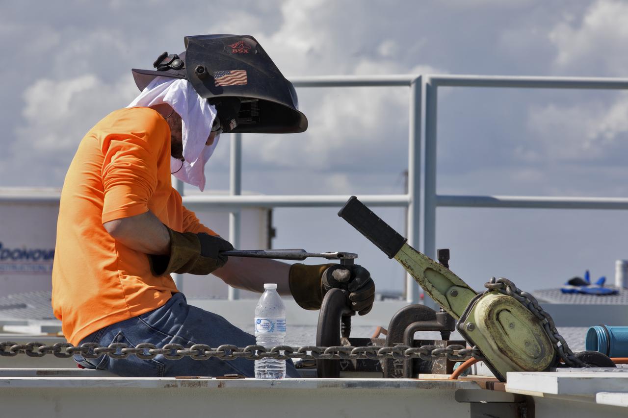
At Launch Pad 39B at NASA's Kennedy Space Center in Florida, cranes lower large segments of the support hardware for a new flame deflector into place in the flame trench. Construction workers weld the structures together. The new flame deflector will be positioned about six feet south of the shuttle-era flame deflector’s position. During liftoff of NASA’s Space Launch System, the rocket’s flame and energy will be diverted to the north side of the flame trench. The north side of the deflector will be protected by a NASA standard coating. The south side of the deflector will not be slanted and will have no lining. The new design will provide easier access for inspection, maintenance and repair. The Ground Systems Development and Operations (GSDO) Program at Kennedy is managing the installation of the flame deflector for Exploration Mission 1, deep space missions, and NASA's Journey to Mars.
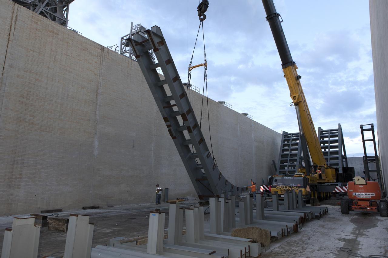
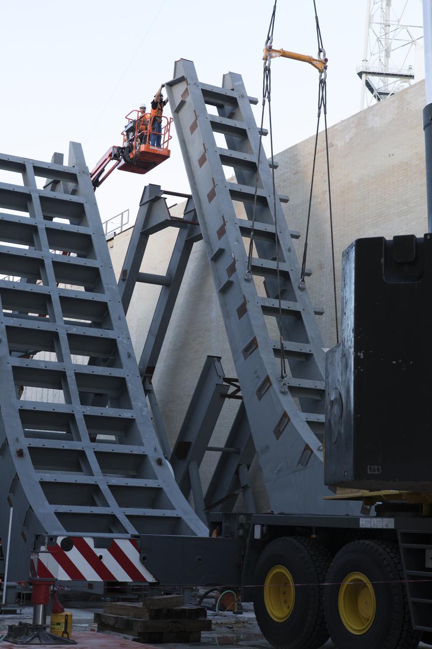
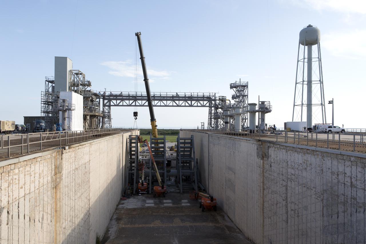
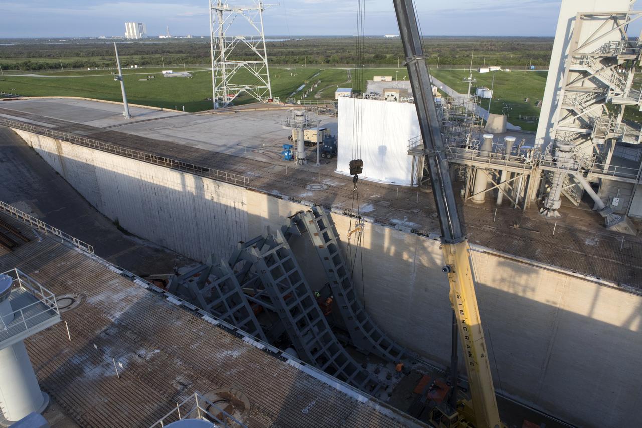
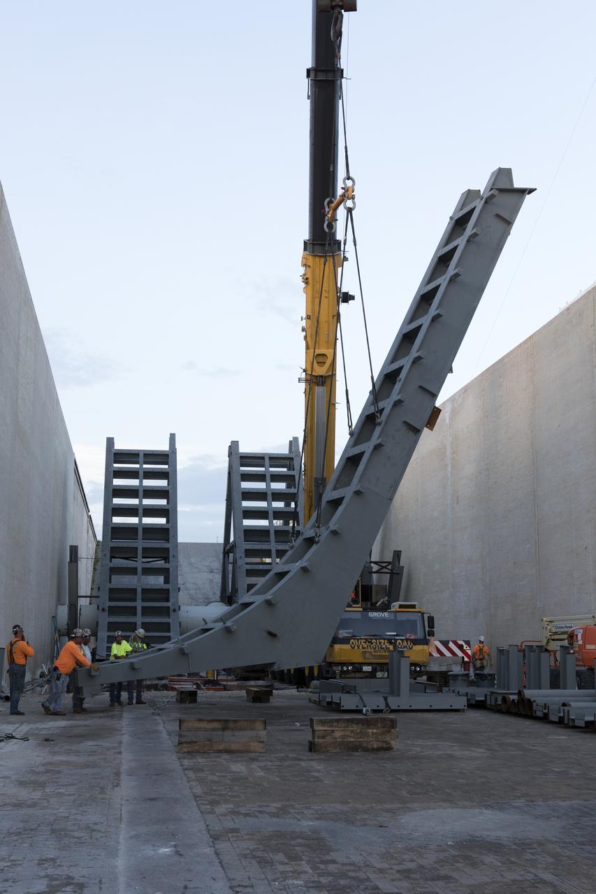
At Launch Pad 39B at NASA's Kennedy Space Center in Florida, a crane is used to move one of the large segments of the support hardware for a new flame deflector and position it in the flame trench. The new flame deflector will be positioned about six feet south of the shuttle-era flame deflector’s position. During liftoff of NASA’s Space Launch System, the rocket’s flame and energy will be diverted to the north side of the flame trench. The north side of the deflector will be protected by a NASA standard coating. The south side of the deflector will not be slanted and will have no lining. The new design will provide easier access for inspection, maintenance and repair. The Ground Systems Development and Operations (GSDO) Program at Kennedy is managing the installation of the flame deflector for Exploration Mission 1, deep space missions, and NASA's Journey to Mars.
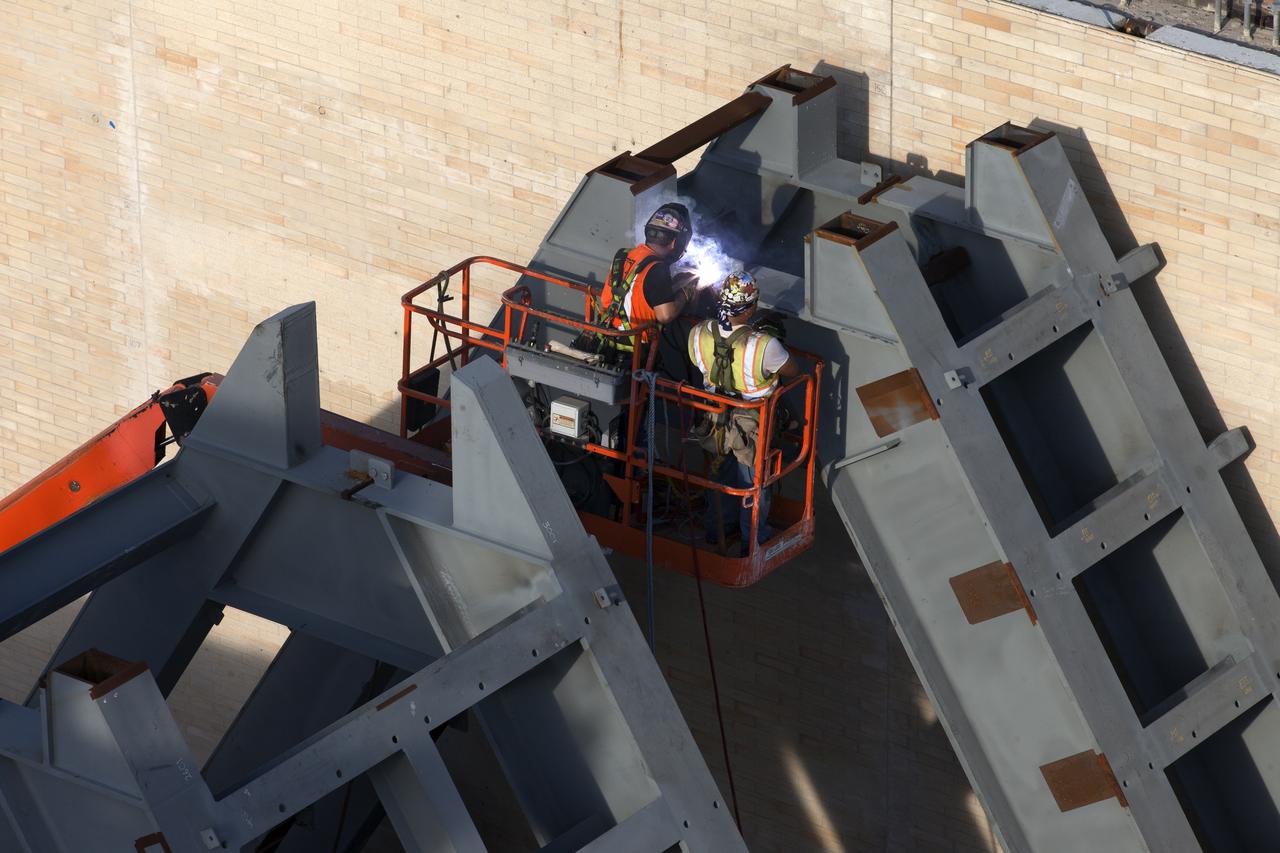
At Launch Pad 39B at NASA's Kennedy Space Center in Florida, construction workers weld together large segments of the support hardware for a new flame deflector in the flame trench. The new flame deflector will be positioned about six feet south of the shuttle-era flame deflector’s position. During liftoff of NASA’s Space Launch System, the rocket’s flame and energy will be diverted to the north side of the flame trench. The north side of the deflector will be protected by a NASA standard coating. The south side of the deflector will not be slanted and will have no lining. The new design will provide easier access for inspection, maintenance and repair. The Ground Systems Development and Operations (GSDO) Program at Kennedy is managing the installation of the flame deflector for Exploration Mission 1, deep space missions, and NASA's Journey to Mars.
At Launch Pad 39B at NASA's Kennedy Space Center in Florida, large segments of the support hardware for a new flame deflector have been lowered into position in the flame trench. The new flame deflector will be positioned about six feet south of the shuttle-era flame deflector’s position. During liftoff of NASA’s Space Launch System, the rocket’s flame and energy will be diverted to the north side of the flame trench. The north side of the deflector will be protected by a NASA standard coating. The south side of the deflector will not be slanted and will have no lining. The new design will provide easier access for inspection, maintenance and repair. The Ground Systems Development and Operations (GSDO) Program at Kennedy is managing the installation of the flame deflector for Exploration Mission 1, deep space missions, and NASA's Journey to Mars.
At Launch Pad 39B at NASA's Kennedy Space Center in Florida, a crane is used to move one of the large segments of the support hardware for a new flame deflector and position it in the flame trench. The new flame deflector will be positioned about six feet south of the shuttle-era flame deflector’s position. During liftoff of NASA’s Space Launch System, the rocket’s flame and energy will be diverted to the north side of the flame trench. The north side of the deflector will be protected by a NASA standard coating. The south side of the deflector will not be slanted and will have no lining. The new design will provide easier access for inspection, maintenance and repair. The Ground Systems Development and Operations (GSDO) Program at Kennedy is managing the installation of the flame deflector for Exploration Mission 1, deep space missions, and NASA's Journey to Mars.

At Launch Pad 39B at NASA's Kennedy Space Center in Florida, cranes lower large segments of the support hardware for a new flame deflector into place in the flame trench. Construction workers weld the structures together. The new flame deflector will be positioned about six feet south of the shuttle-era flame deflector’s position. During liftoff of NASA’s Space Launch System, the rocket’s flame and energy will be diverted to the north side of the flame trench. The north side of the deflector will be protected by a NASA standard coating. The south side of the deflector will not be slanted and will have no lining. The new design will provide easier access for inspection, maintenance and repair. The Ground Systems Development and Operations (GSDO) Program at Kennedy is managing the installation of the flame deflector for Exploration Mission 1, deep space missions, and NASA's Journey to Mars.
At Launch Pad 39B at NASA's Kennedy Space Center in Florida, large segments of the support hardware for a new flame deflector have been lowered into position in the flame trench. The new flame deflector will be positioned about six feet south of the shuttle-era flame deflector’s position. During liftoff of NASA’s Space Launch System, the rocket’s flame and energy will be diverted to the north side of the flame trench. The north side of the deflector will be protected by a NASA standard coating. The south side of the deflector will not be slanted and will have no lining. The new design will provide easier access for inspection, maintenance and repair. The Ground Systems Development and Operations (GSDO) Program at Kennedy is managing the installation of the flame deflector for Exploration Mission 1, deep space missions, and NASA's Journey to Mars.
At Launch Pad 39B at NASA's Kennedy Space Center in Florida, construction workers prepare to weld together large segments of the support hardware for a new flame deflector in the flame trench. The new flame deflector will be positioned about six feet south of the shuttle-era flame deflector’s position. During liftoff of NASA’s Space Launch System, the rocket’s flame and energy will be diverted to the north side of the flame trench. The north side of the deflector will be protected by a NASA standard coating. The south side of the deflector will not be slanted and will have no lining. The new design will provide easier access for inspection, maintenance and repair. The Ground Systems Development and Operations (GSDO) Program at Kennedy is managing the installation of the flame deflector for Exploration Mission 1, deep space missions, and NASA's Journey to Mars.
At Launch Pad 39B at NASA's Kennedy Space Center in Florida, a crane is used to move one of the large segments of the support hardware for a new flame deflector and position it in the flame trench. The new flame deflector will be positioned about six feet south of the shuttle-era flame deflector’s position. During liftoff of NASA’s Space Launch System, the rocket’s flame and energy will be diverted to the north side of the flame trench. The north side of the deflector will be protected by a NASA standard coating. The south side of the deflector will not be slanted and will have no lining. The new design will provide easier access for inspection, maintenance and repair. The Ground Systems Development and Operations (GSDO) Program at Kennedy is managing the installation of the flame deflector for Exploration Mission 1, deep space missions, and NASA's Journey to Mars.
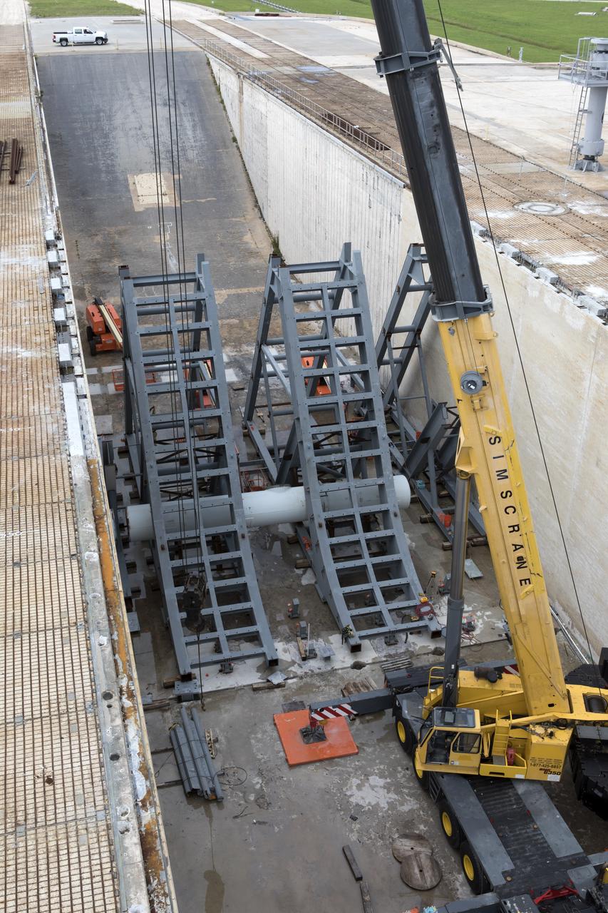
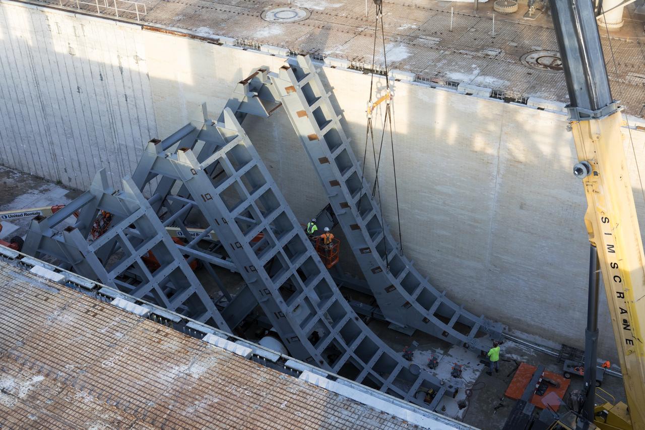
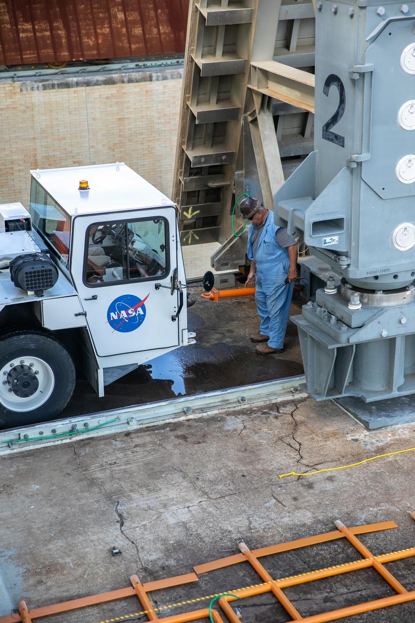
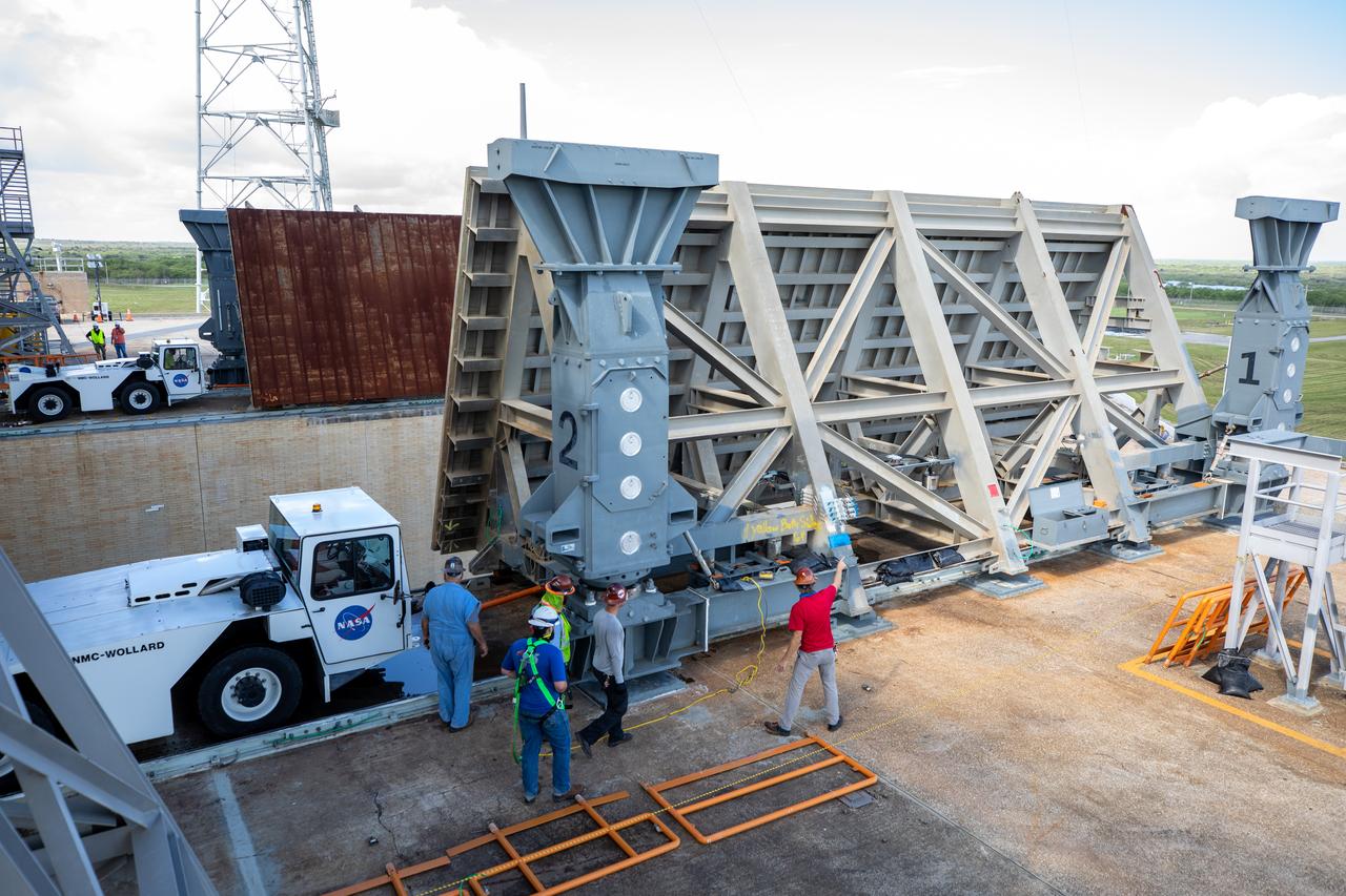
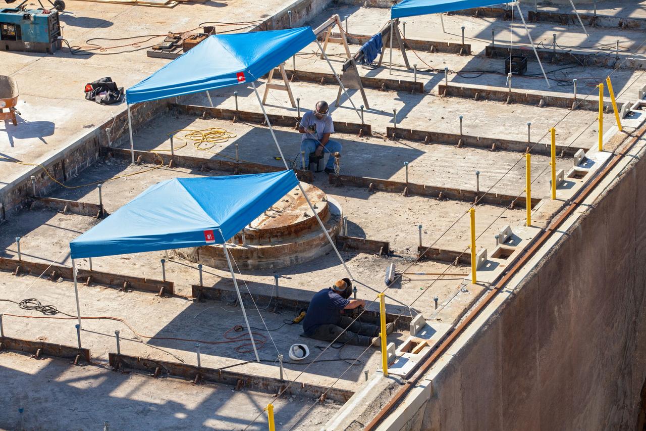
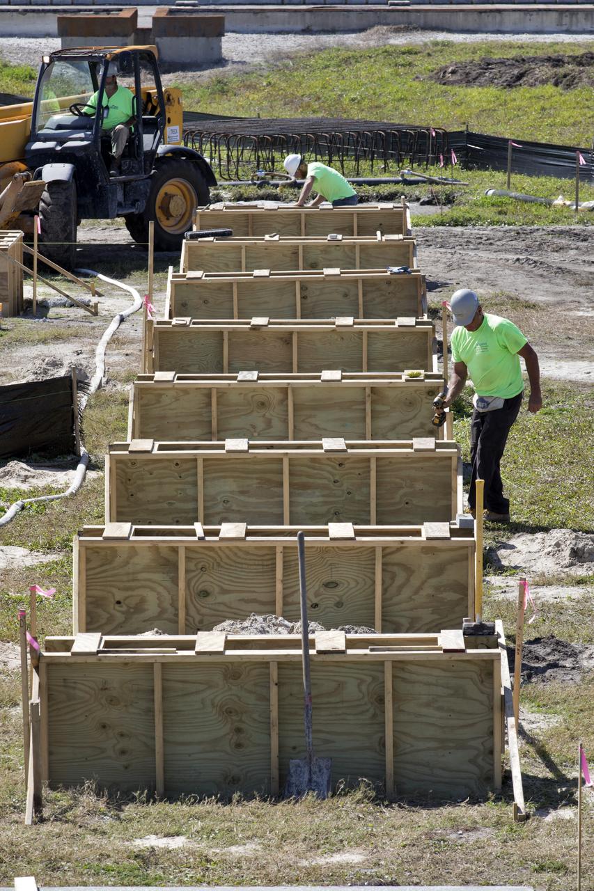
In a view from above at Launch Pad 39B at NASA's Kennedy Space Center in Florida, construction workers position large segments of the support hardware for a new flame deflector in the flame trench. The new flame deflector will be positioned about six feet south of the shuttle-era flame deflector’s position. During liftoff of NASA’s Space Launch System, the rocket’s flame and energy will be diverted to the north side of the flame trench. The north side of the deflector will be protected by a NASA standard coating. The south side of the deflector will not be slanted and will have no lining. The new design will provide easier access for inspection, maintenance and repair. The Ground Systems Development and Operations (GSDO) Program at Kennedy is managing the installation of the flame deflector for Exploration Mission 1, deep space missions, and NASA's Journey to Mars.
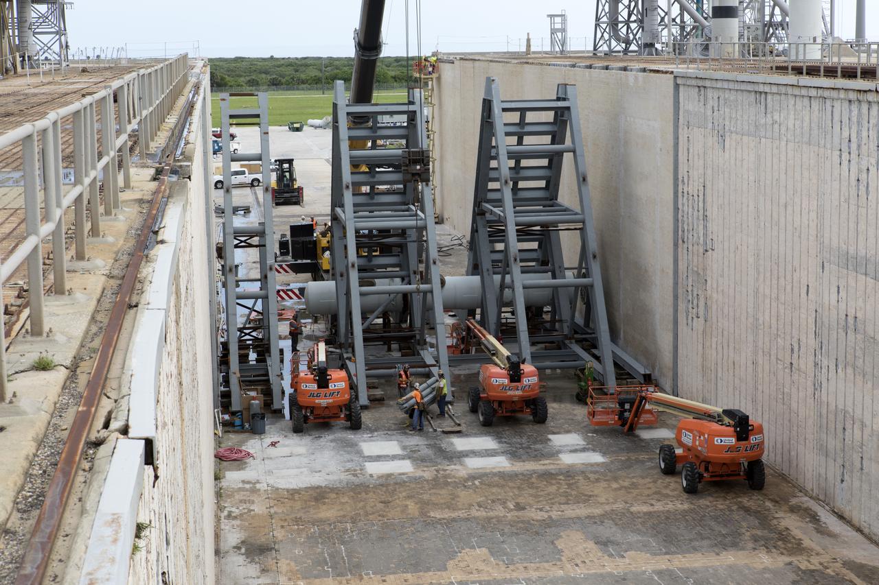
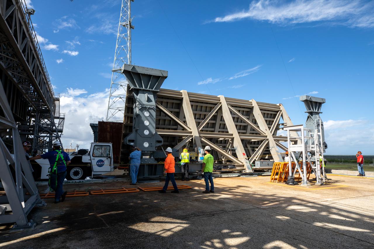
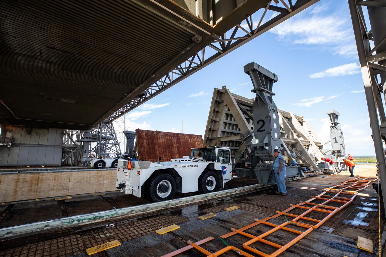
At Launch Pad 39B at NASA's Kennedy Space Center in Florida, construction workers position large segments of the support hardware for a new flame deflector in the flame trench. The new flame deflector will be positioned about six feet south of the shuttle-era flame deflector’s position. During liftoff of NASA’s Space Launch System, the rocket’s flame and energy will be diverted to the north side of the flame trench. The north side of the deflector will be protected by a NASA standard coating. The south side of the deflector will not be slanted and will have no lining. The new design will provide easier access for inspection, maintenance and repair. The Ground Systems Development and Operations (GSDO) Program at Kennedy is managing the installation of the flame deflector for Exploration Mission 1, deep space missions, and NASA's Journey to Mars.

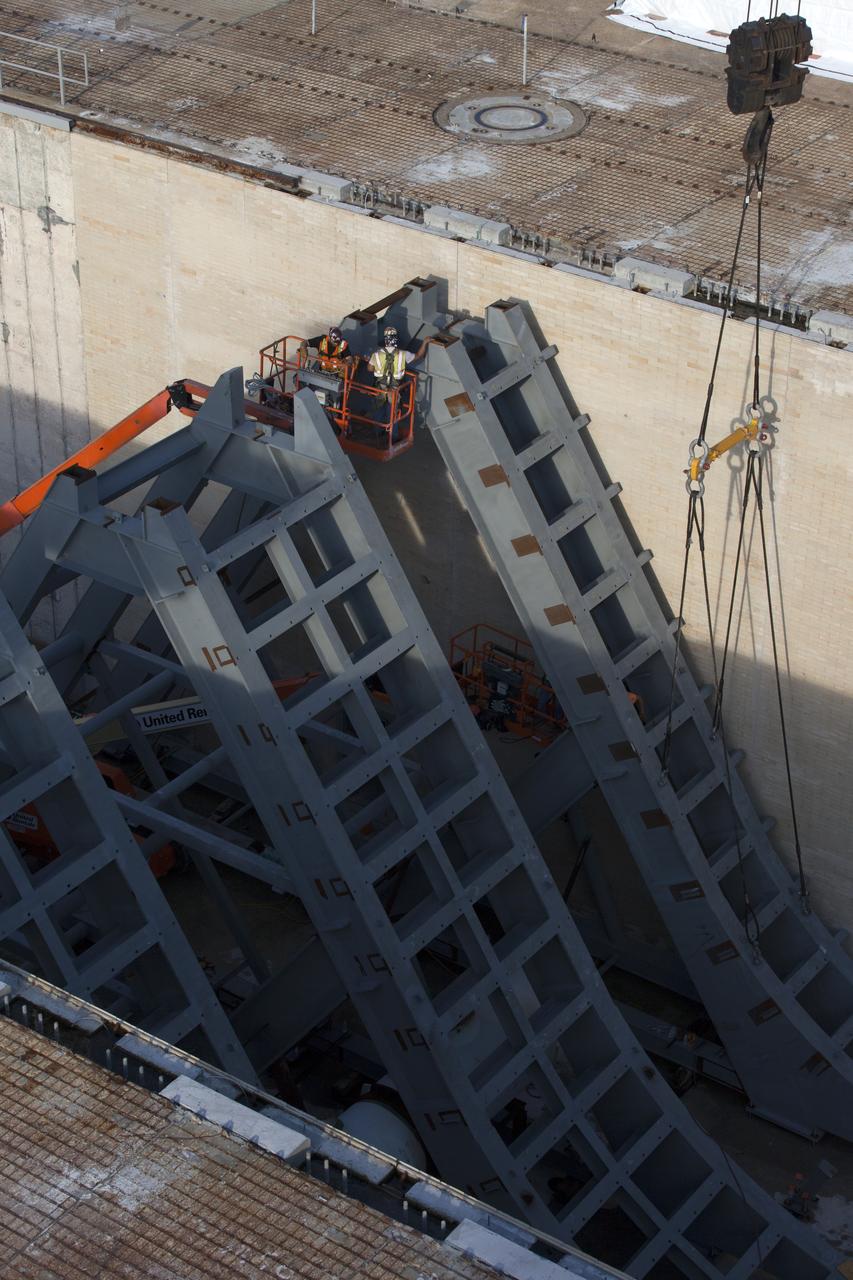
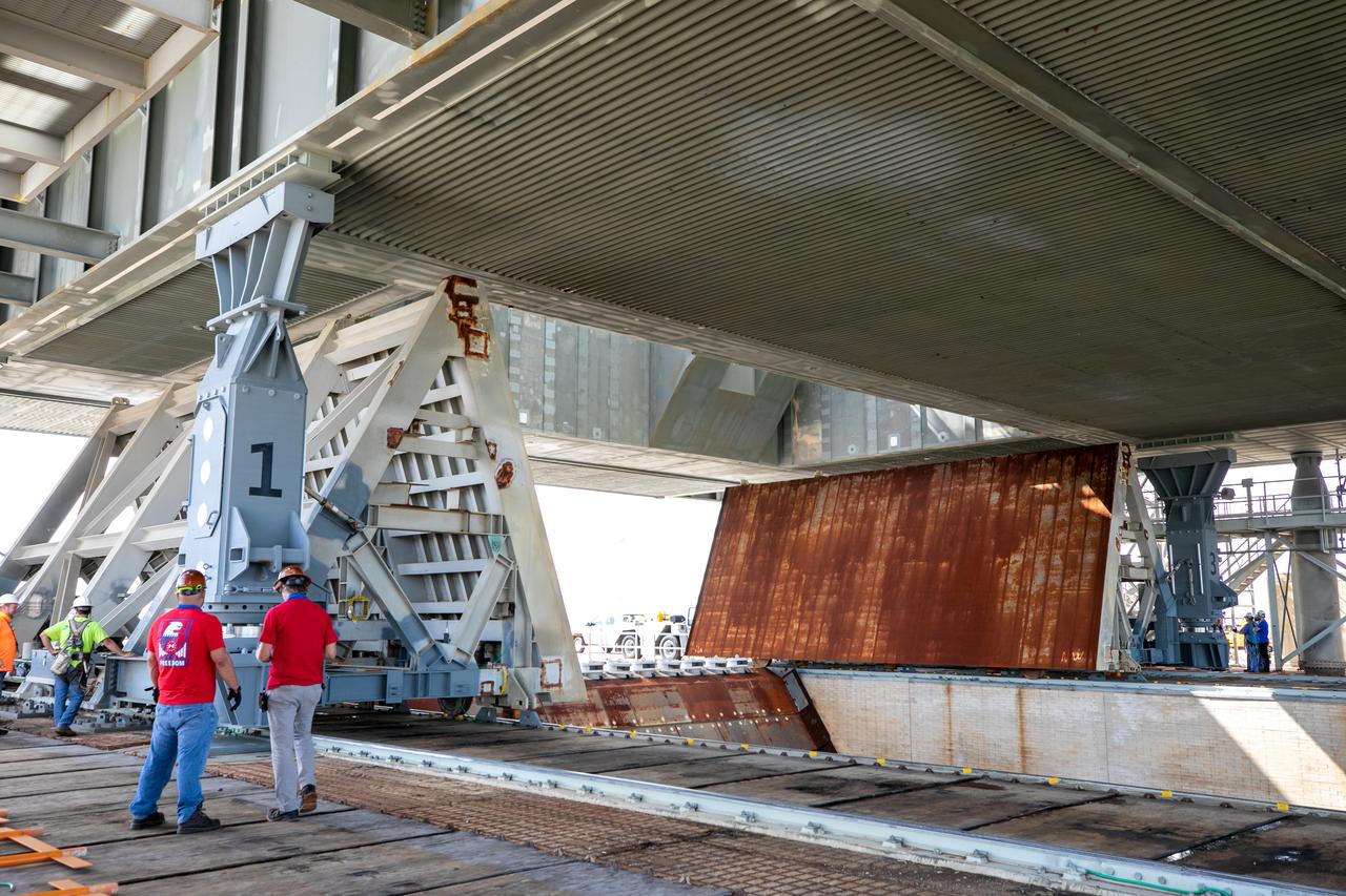
At Launch Pad 39B at NASA's Kennedy Space Center in Florida, construction workers position large segments of the support hardware for a new flame deflector in the flame trench. The new flame deflector will be positioned about six feet south of the shuttle-era flame deflector’s position. During liftoff of NASA’s Space Launch System, the rocket’s flame and energy will be diverted to the north side of the flame trench. The north side of the deflector will be protected by a NASA standard coating. The south side of the deflector will not be slanted and will have no lining. The new design will provide easier access for inspection, maintenance and repair. The Ground Systems Development and Operations (GSDO) Program at Kennedy is managing the installation of the flame deflector for Exploration Mission 1, deep space missions, and NASA's Journey to Mars.
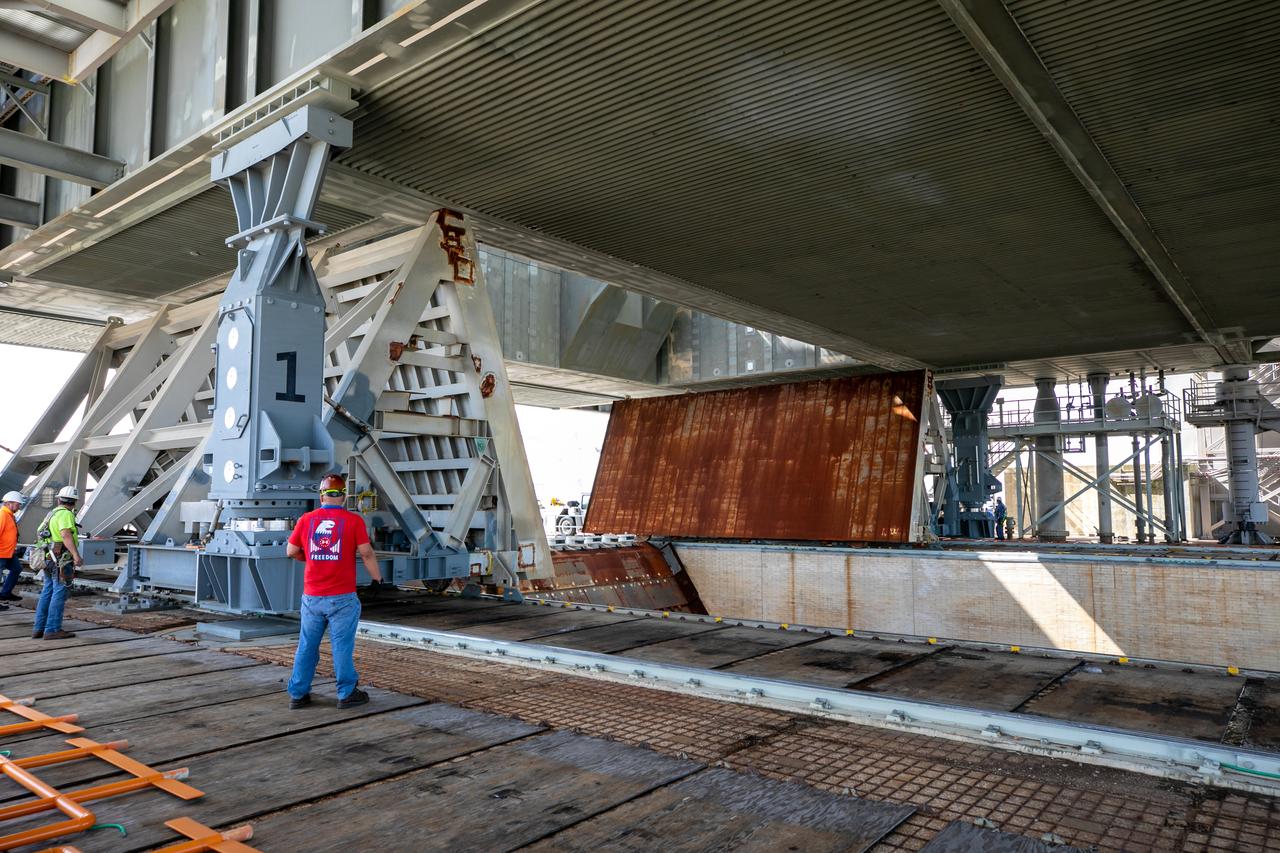
At Launch Pad 39B at NASA's Kennedy Space Center in Florida, construction workers position large segments of the support hardware for a new flame deflector in the flame trench. The new flame deflector will be positioned about six feet south of the shuttle-era flame deflector’s position. During liftoff of NASA’s Space Launch System, the rocket’s flame and energy will be diverted to the north side of the flame trench. The north side of the deflector will be protected by a NASA standard coating. The south side of the deflector will not be slanted and will have no lining. The new design will provide easier access for inspection, maintenance and repair. The Ground Systems Development and Operations (GSDO) Program at Kennedy is managing the installation of the flame deflector for Exploration Mission 1, deep space missions, and NASA's Journey to Mars.
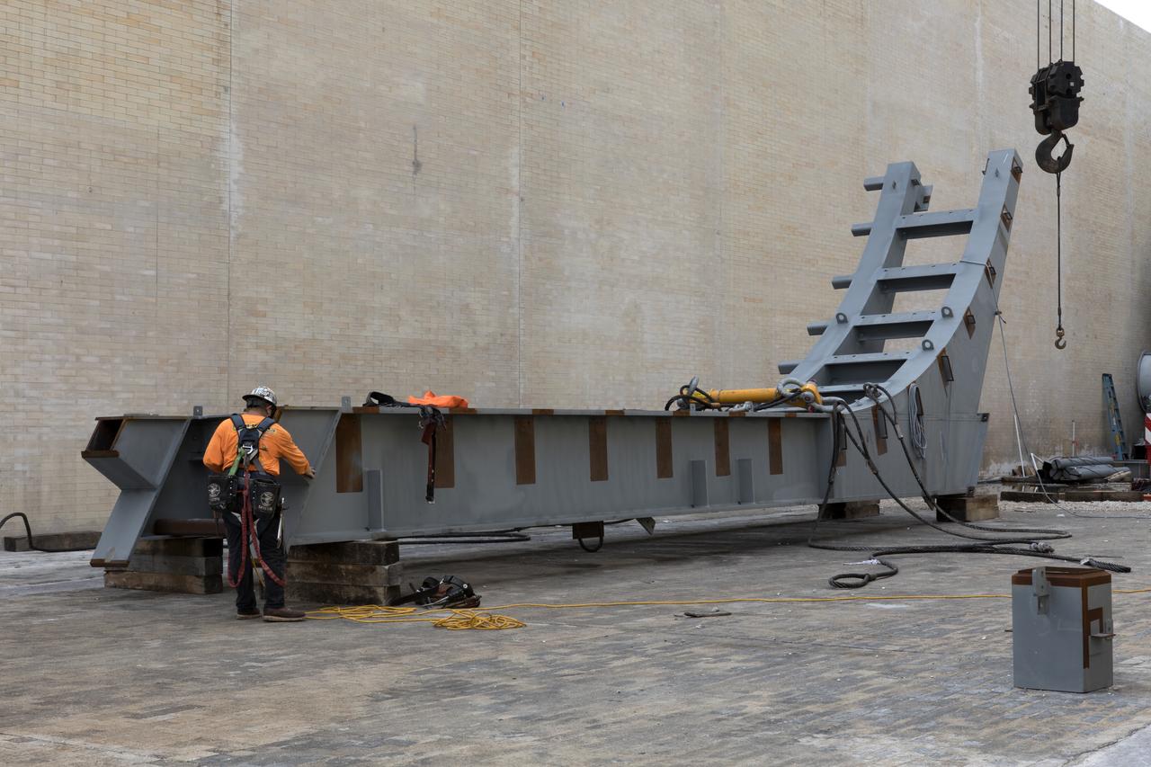
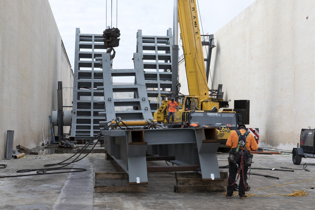
At Launch Pad 39B at NASA's Kennedy Space Center in Florida, a construction worker prepares a large segments of the support hardware for a new flame deflector to be lifted into place in the flame trench. The new flame deflector will be positioned about six feet south of the shuttle-era flame deflector’s position. During liftoff of NASA’s Space Launch System, the rocket’s flame and energy will be diverted to the north side of the flame trench. The north side of the deflector will be protected by a NASA standard coating. The south side of the deflector will not be slanted and will have no lining. The new design will provide easier access for inspection, maintenance and repair. The Ground Systems Development and Operations (GSDO) Program at Kennedy is managing the installation of the flame deflector for Exploration Mission 1, deep space missions, and NASA's Journey to Mars.
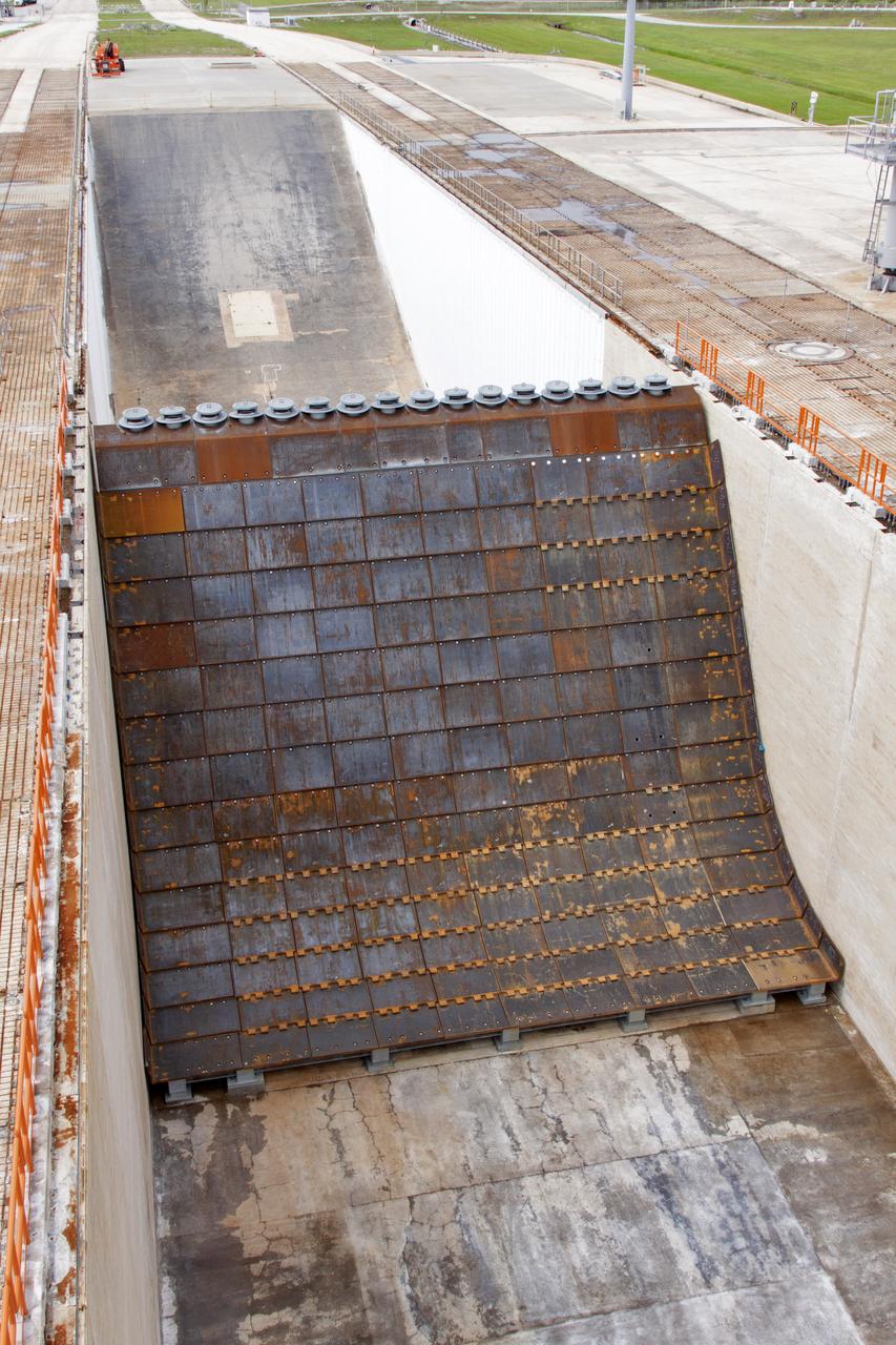
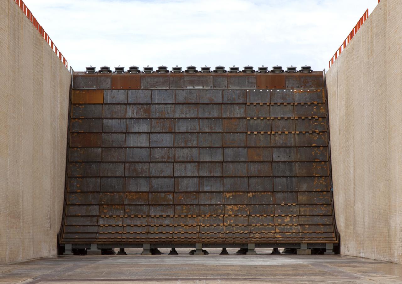
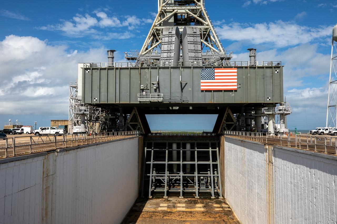
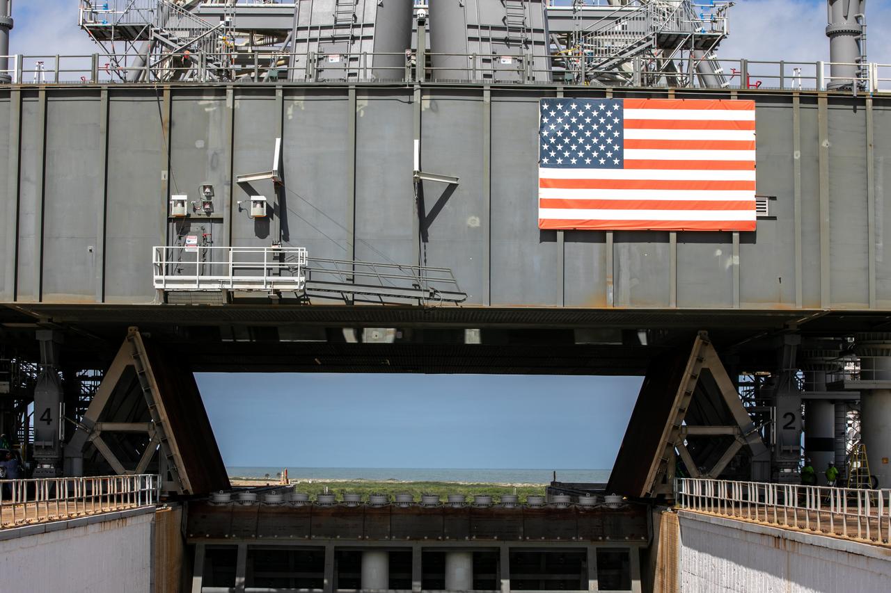
Construction is complete on the main flame deflector in the flame trench at Launch Complex 39B at NASA's Kennedy Space Center in Florida. The flame deflector will safely deflect the plume exhaust from NASA's Space Launch System rocket during launch. It will divert the rocket's exhaust, pressure and intense heat to the north at liftoff. In view is the south side of the main flame deflector. The Exploration Ground Systems Program at Kennedy is refurbishing the pad to support the launch of the SLS rocket and Orion on Exploration Mission-1, and helping to transform the space center into a multi-user spaceport.
Construction is complete on the main flame deflector in the flame trench at Launch Complex 39B at NASA's Kennedy Space Center in Florida. The flame deflector will safely deflect the plume exhaust from NASA's Space Launch System rocket during launch. It will divert the rocket's exhaust, pressure and intense heat to the north at liftoff. The Exploration Ground Systems Program at Kennedy is refurbishing the pad to support the launch of the SLS rocket and Orion on Exploration Mission-1, and helping to transform the space center into a multi-user spaceport.
Construction is complete on the main flame deflector in the flame trench at Launch Complex 39B at NASA's Kennedy Space Center in Florida. The flame deflector will safely deflect the plume exhaust from NASA's Space Launch System rocket during launch. It will divert the rocket's exhaust, pressure and intense heat to the north at liftoff. The Exploration Ground Systems Program at Kennedy is refurbishing the pad to support the launch of the SLS rocket and Orion on Exploration Mission-1, and helping to transform the space center into a multi-user spaceport.
Construction is complete on the main flame deflector in the flame trench at Launch Complex 39B at NASA's Kennedy Space Center in Florida. The flame deflector will safely deflect the plume exhaust from NASA's Space Launch System rocket during launch. It will divert the rocket's exhaust, pressure and intense heat to the north at liftoff. The Exploration Ground Systems Program at Kennedy is refurbishing the pad to support the launch of the SLS rocket and Orion on Exploration Mission-1, and helping to transform the space center into a multi-user spaceport.
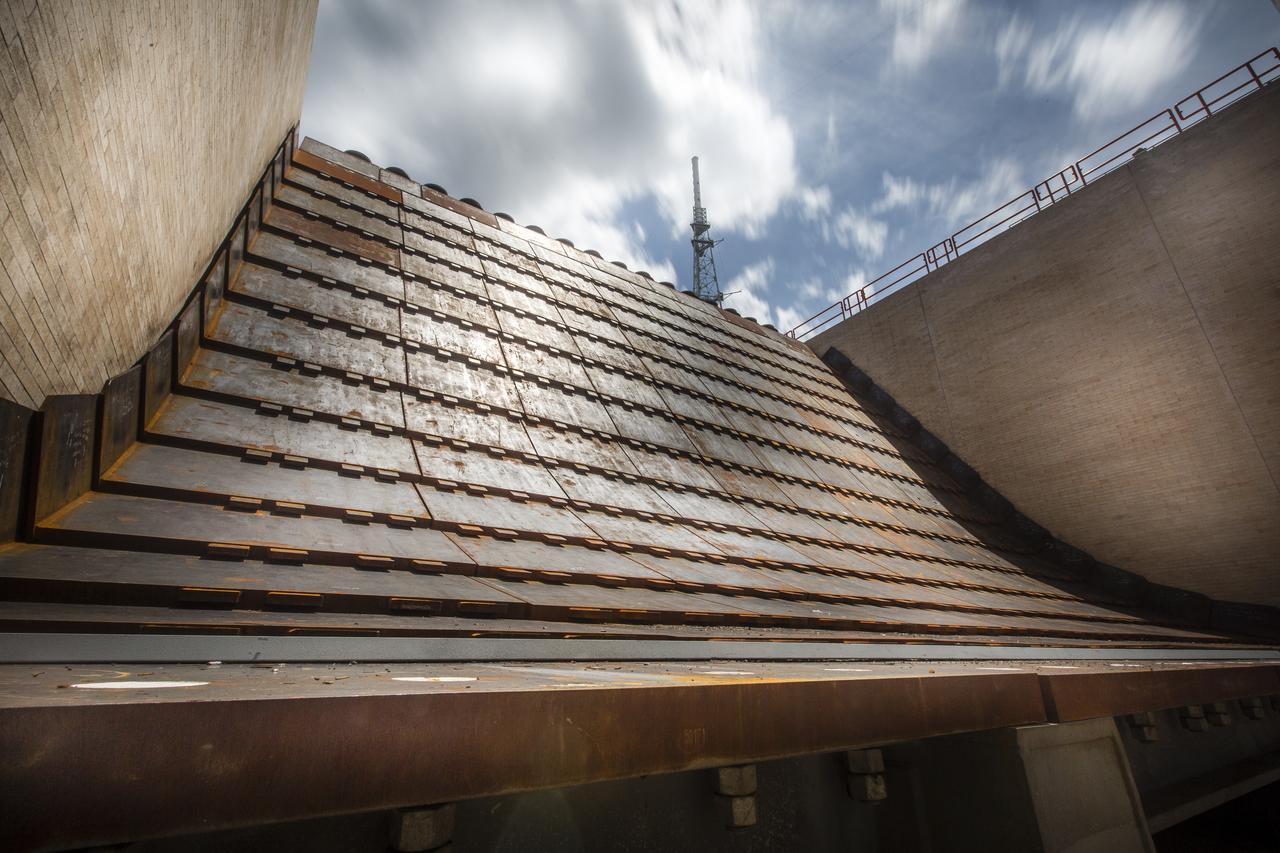
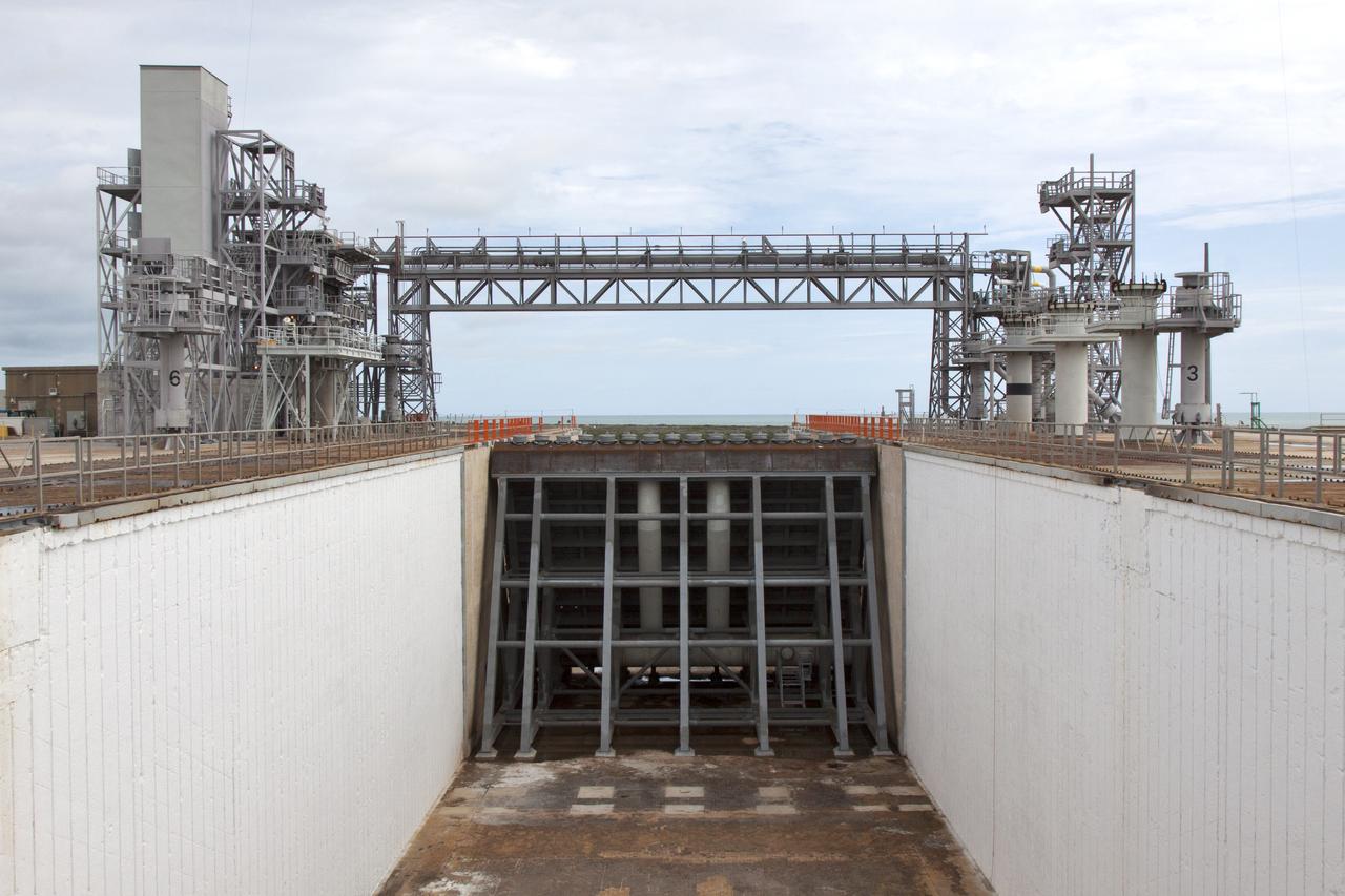
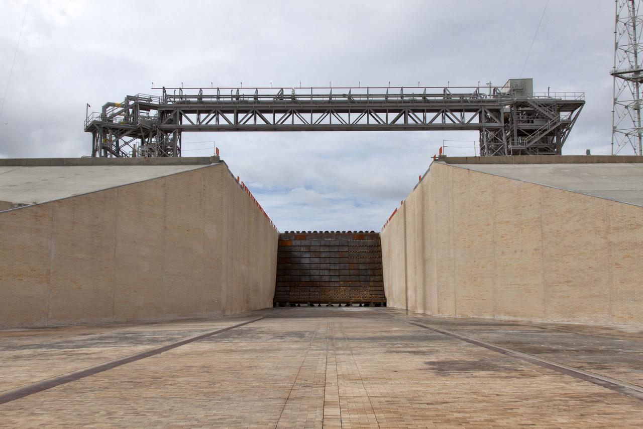
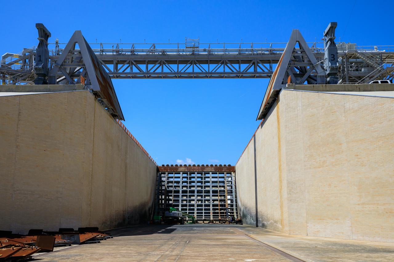
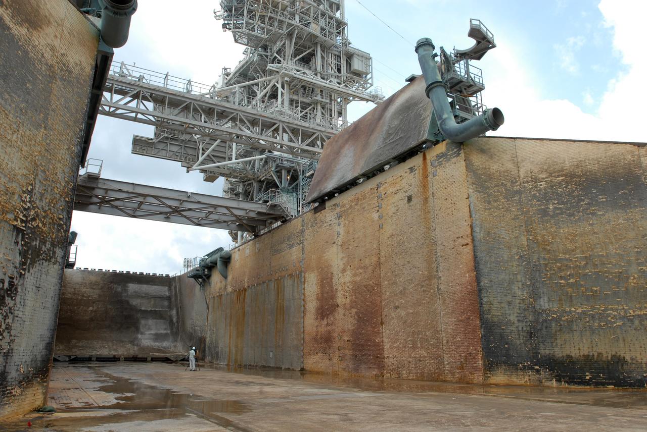
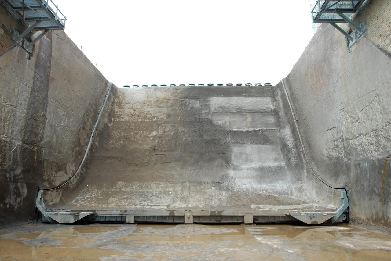
A close-up view of the flame trench and flame deflector at Launch Pad 39B at NASA's Kennedy Space Center in Florida on July 26, 2018. The launch pad has undergone upgrades and modifications to accommodate NASA's Space Launch System and Orion spacecraft for Exploration Mission-1 and other deep space missions. New heat-resistant bricks have been installed on the walls and a new flame deflector is in place. The clean pad concept is designed to support NASA and commercial launch providers at the multi-user spaceport.
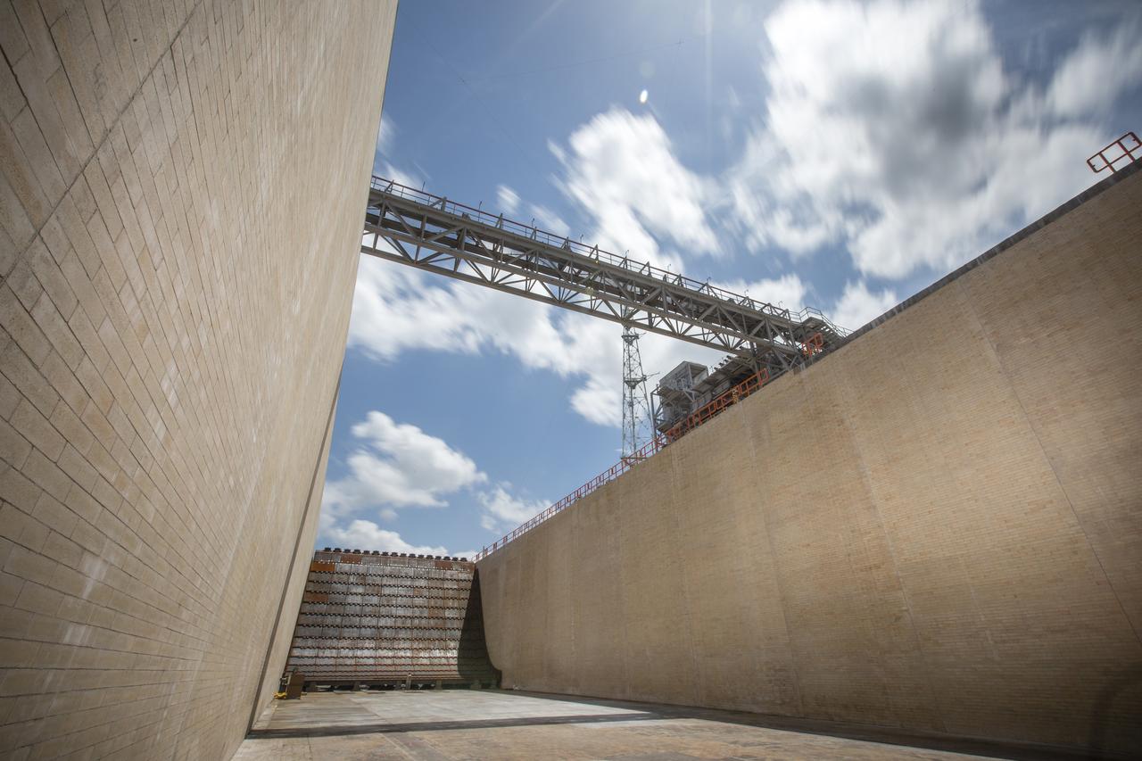
The flame trench and flame deflector are in view at Launch Pad 39B at NASA's Kennedy Space Center in Florida on July 26, 2018. The launch pad has undergone upgrades and modifications to accommodate NASA's Space Launch System and Orion spacecraft for Exploration Mission-1 and other deep space missions. New heat-resistant bricks have been installed on the walls and a new flame deflector is in place. The clean pad concept is designed to support NASA and commercial launch providers at the multi-user spaceport.
A close-up view of the flame trench and flame deflector at Launch Pad 39B at NASA's Kennedy Space Center in Florida on July 26, 2018. The launch pad has undergone upgrades and modifications to accommodate NASA's Space Launch System and Orion spacecraft for Exploration Mission-1 and other deep space missions. New heat-resistant bricks have been installed on the walls and a new flame deflector is in place. The clean pad concept is designed to support NASA and commercial launch providers at the multi-user spaceport.
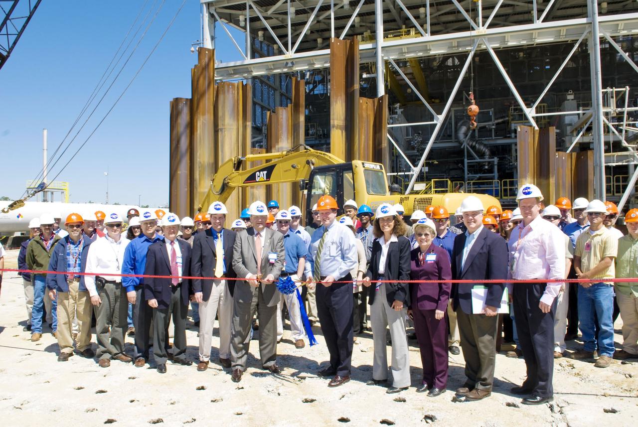
Representatives from NASA, Orbital Sciences Corp. and Aerojet participate in a ribbon-cutting ceremony for construction of a flame deflector trench at Stennis Space Center's E Test Complex. Participants included Orbital CEO J.R. Thompson (center, left) and Stennis Space Center Director Gene Goldman (center, right).
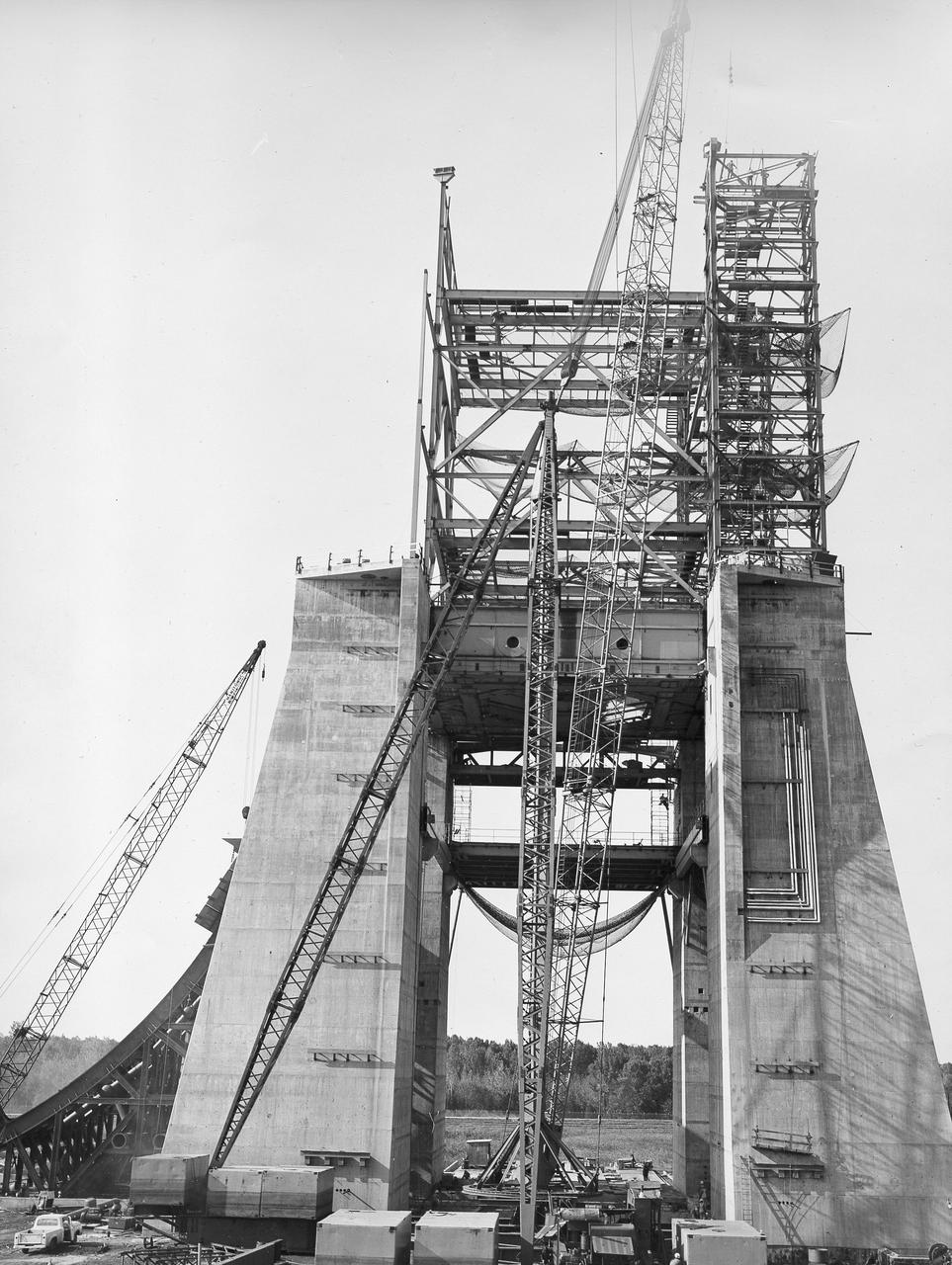
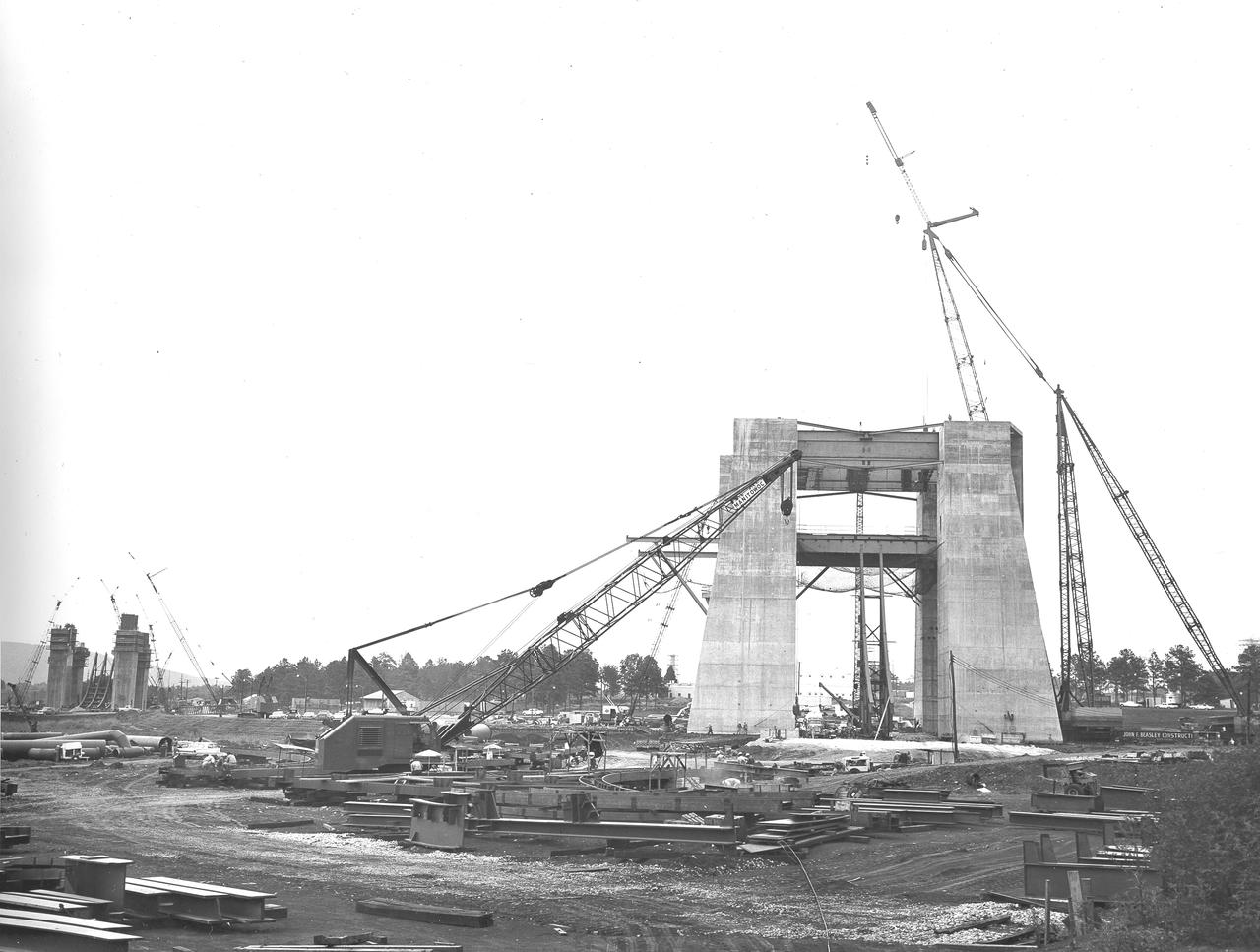
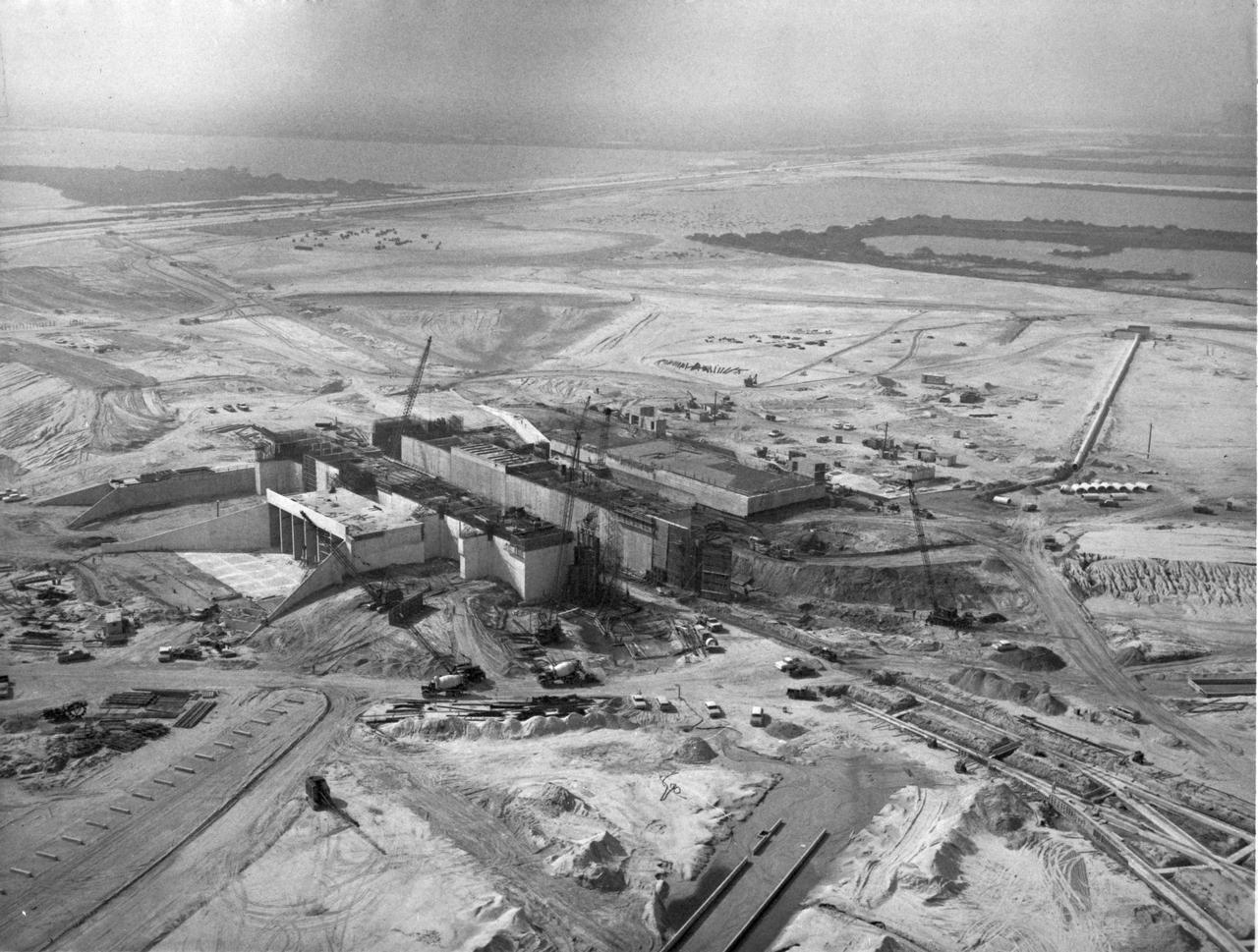
At its founding, the Marshall Space Flight Center (MSFC) inherited the Army’s Jupiter and Redstone test stands, but much larger facilities were needed for the giant stages of the Saturn V. From 1960 to 1964, the existing stands were remodeled and a sizable new test area was developed. The new comprehensive test complex for propulsion and structural dynamics was unique within the nation and the free world, and they remain so today because they were constructed with foresight to meet the future as well as on going needs. Construction of the S-IC Static test stand complex began in 1961 in the west test area of MSFC, and was completed in 1964. The S-IC static test stand was designed to develop and test the 138-ft long and 33-ft diameter Saturn V S-IC first stage, or booster stage, weighing in at 280,000 pounds. Required to hold down the brute force of a 7,500,000-pound thrust produced by 5 F-1 engines, the S-IC static test stand was designed and constructed with the strength of hundreds of tons of steel and 12,000,000 pounds of cement, planted down to bedrock 40 feet below ground level. The foundation walls, constructed with concrete and steel, are 4 feet thick. The base structure consists of four towers with 40-foot-thick walls extending upward 144 feet above ground level. The structure was topped by a crane with a 135-foot boom. With the boom in the upright position, the stand was given an overall height of 405 feet, placing it among the highest structures in Alabama at the time. In addition to the stand itself, related facilities were constructed during this time. Built to the northeast of the stand was a newly constructed Pump House. Its function was to provide water to the stand to prevent melting damage during testing. The water was sprayed through small holes in the stand’s 1900 ton flame deflector at the rate of 320,000 gallons per minute. In this photo of the S-IC test stand, taken September 25, 1963, the flame deflector can be seen rotated to the outside on the left. The deflector was assembled on tracks for mobility.
At its founding, the Marshall Space Flight Center (MSFC) inherited the Army’s Jupiter and Redstone test stands, but much larger facilities were needed for the giant stages of the Saturn V. From 1960 to 1964, the existing stands were remodeled and a sizable new test area was developed. The new comprehensive test complex for propulsion and structural dynamics was unique within the nation and the free world, and they remain so today because they were constructed with foresight to meet the future as well as on going needs. Construction of the S-IC Static test stand complex began in 1961 in the west test area of MSFC, and was completed in 1964. The S-IC static test stand was designed to develop and test the 138-ft long and 33-ft diameter Saturn V S-IC first stage, or booster stage, weighing in at 280,000 pounds. Required to hold down the brute force of a 7,500,000-pound thrust produced by 5 F-1 engines, the S-IC static test stand was designed and constructed with the strength of hundreds of tons of steel and 12,000,000 pounds of cement, planted down to bedrock 40 feet below ground level. The foundation walls, constructed with concrete and steel, are 4 feet thick. The base structure consists of four towers with 40-foot-thick walls extending upward 144 feet above ground level. The structure was topped by a crane with a 135-foot boom. With the boom in the upright position, the stand was given an overall height of 405 feet, placing it among the highest structures in Alabama at the time. In addition to the stand itself, related facilities were constructed during this time. Built to the northeast of the stand was a newly constructed Pump House. Its function was to provide water to the stand to prevent melting damage during testing. The water was sprayed through small holes in the stand’s 1900 ton flame deflector at the rate of 320,000 gallons per minute. In this photo of the S-IC test stand, taken September 25, 1963, the flame deflector can be seen rotated to the outside on the right. The deflector was assembled on tracks for mobility.
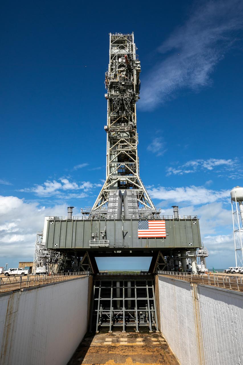
A view of the mobile launcher for Artemis I with the two side flame deflectors positioned underneath during a countdown demonstration test at Launch Pad 39B at NASA’s Kennedy Space Center in Florida on Oct. 23, 2020. Also in view is the main flame deflector in the flame trench. The nearly 400-foot-tall mobile launcher is at the pad while engineers with Exploration Ground Systems and Jacobs complete several tasks, including a timing test to validate the launch team’s countdown timeline, and a thorough, top-to-bottom wash down of the mobile launcher to remove any debris remaining from construction and installation of the umbilical arms. Artemis I will test the Orion spacecraft and Space Launch System as an integrated system ahead of crewed flights to the Moon. Under the Artemis program, NASA will land the first woman and the next man on the Moon in 2024.
A close-up view of the mobile launcher for Artemis I with the two side flame deflectors positioned underneath during a countdown demonstration test at Launch Pad 39B at NASA’s Kennedy Space Center in Florida on Oct. 23, 2020. Also in view is the main flame deflector in the flame trench. The nearly 400-foot-tall mobile launcher is at the pad while engineers with Exploration Ground Systems and Jacobs complete several tasks, including a timing test to validate the launch team’s countdown timeline, and a thorough, top-to-bottom wash down of the mobile launcher to remove any debris remaining from construction and installation of the umbilical arms. Artemis I will test the Orion spacecraft and Space Launch System as an integrated system ahead of crewed flights to the Moon. Under the Artemis program, NASA will land the first woman and the next man on the Moon in 2024.
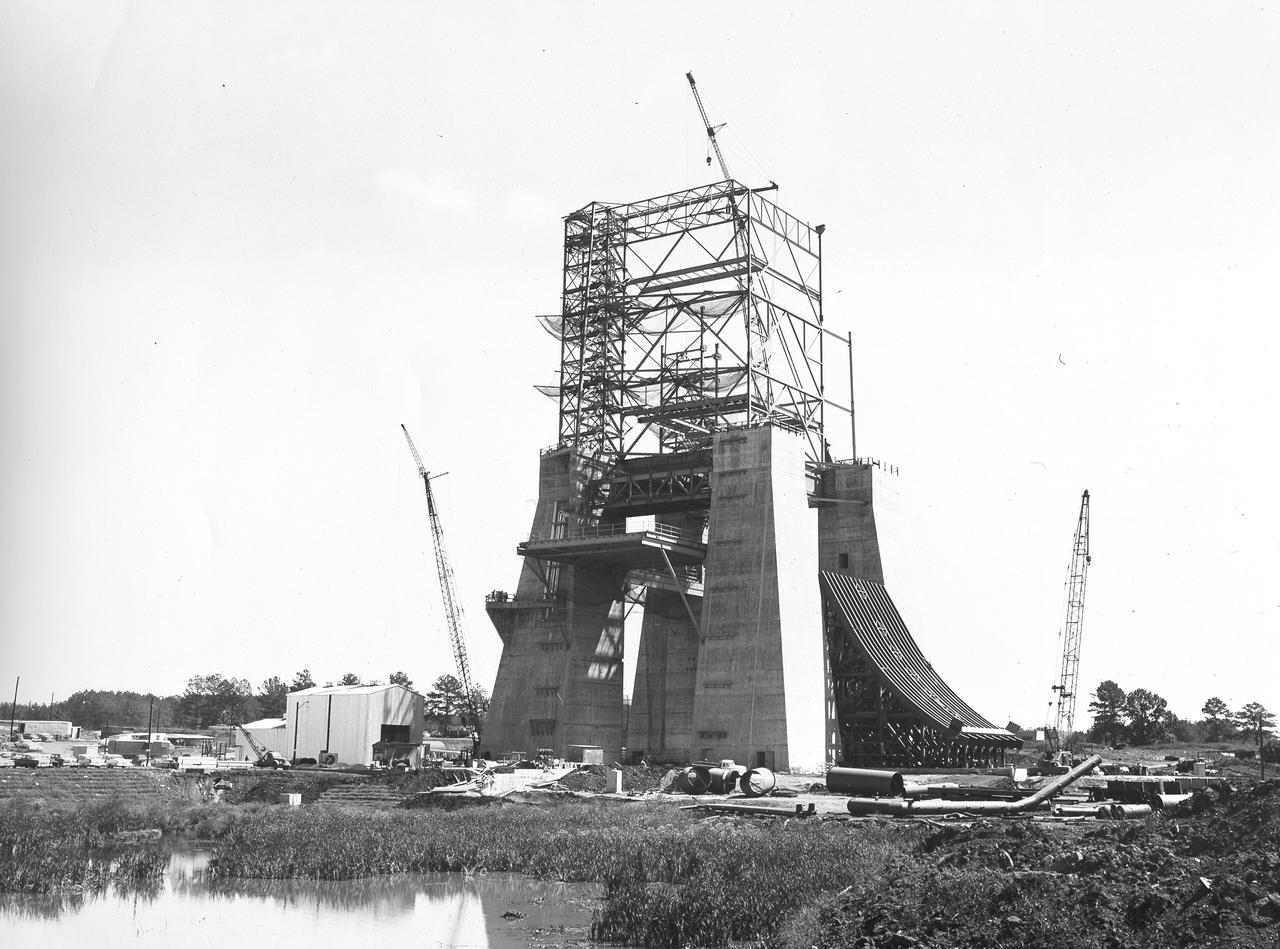
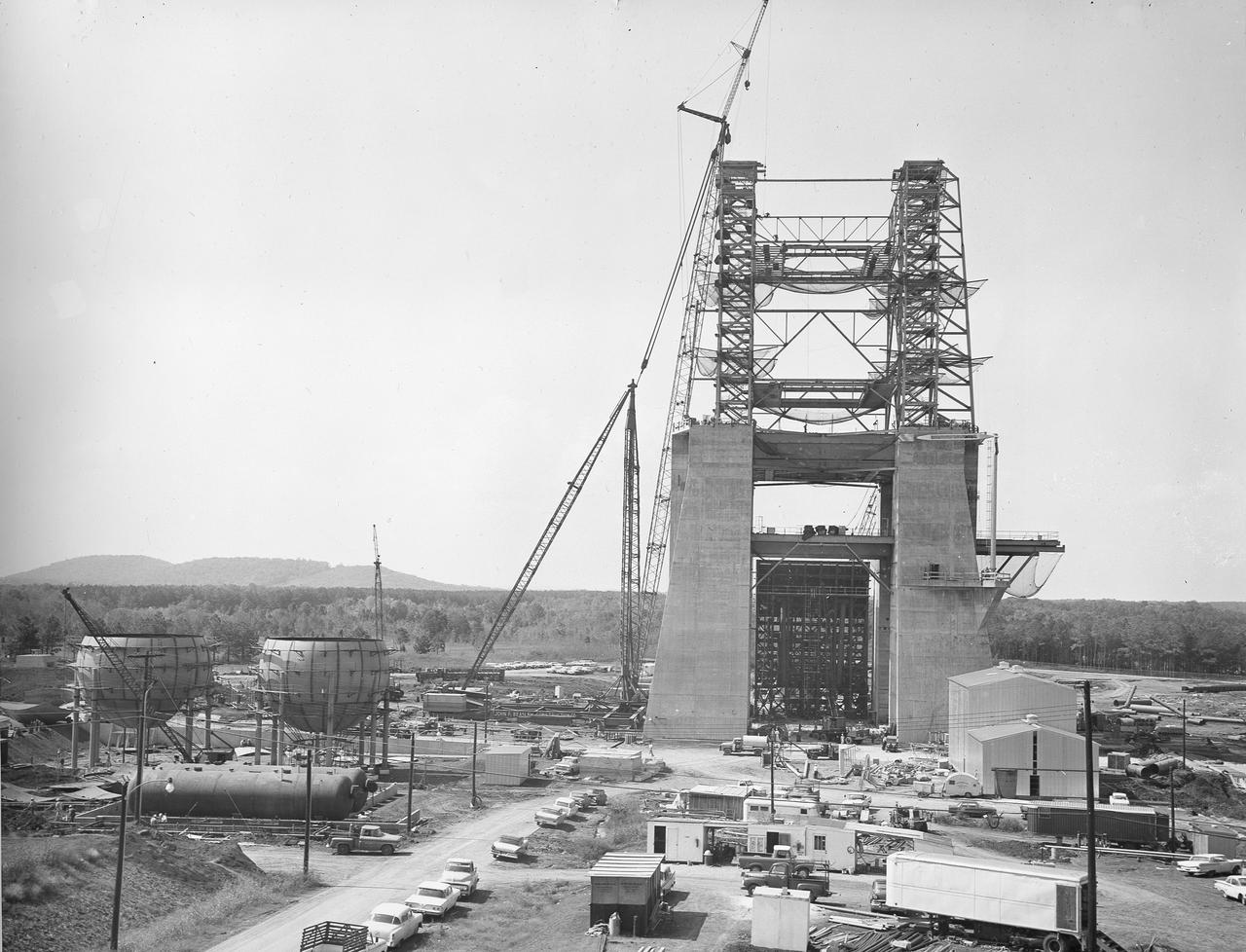
At its founding, the Marshall Space Flight Center (MSFC) inherited the Army’s Jupiter and Redstone test stands, but much larger facilities were needed for the giant stages of the Saturn V. From 1960 to 1964, the existing stands were remodeled and a sizable new test area was developed. The new comprehensive test complex for propulsion and structural dynamics was unique within the nation and the free world, and they remain so today because they were constructed with foresight to meet the future as well as on going needs. Construction of the S-IC Static test stand complex began in 1961 in the west test area of MSFC, and was completed in 1964. The S-IC static test stand was designed to develop and test the 138-ft long and 33-ft diameter Saturn V S-IC first stage, or booster stage, weighing in at 280,000 pounds. Required to hold down the brute force of a 7,500,000-pound thrust produced by 5 F-1 engines, the S-IC static test stand was designed and constructed with the strength of hundreds of tons of steel and 12,000,000 pounds of cement, planted down to bedrock 40 feet below ground level. The foundation walls, constructed with concrete and steel, are 4 feet thick. The base structure consists of four towers with 40-foot-thick walls extending upward 144 feet above ground level. The structure was topped by a crane with a 135-foot boom. With the boom in the upright position, the stand was given an overall height of 405 feet, placing it among the highest structures in Alabama at the time. In addition to the stand itself, related facilities were constructed during this time. Built to the east was a newly constructed Pump House. Its function was to provide water to the stand to prevent melting damage during testing. The water was sprayed through small holes in the stand’s 1900 ton flame deflector at the rate of 320,000 gallons per minute. In this photo, taken August 12, 1963, the S-IC stand has received some of its internal components. Directly in the center is the framework that houses the flame deflector. The F-1 test stand, designed and built to test a single F-1 engine, can be seen on the left side of the photo.
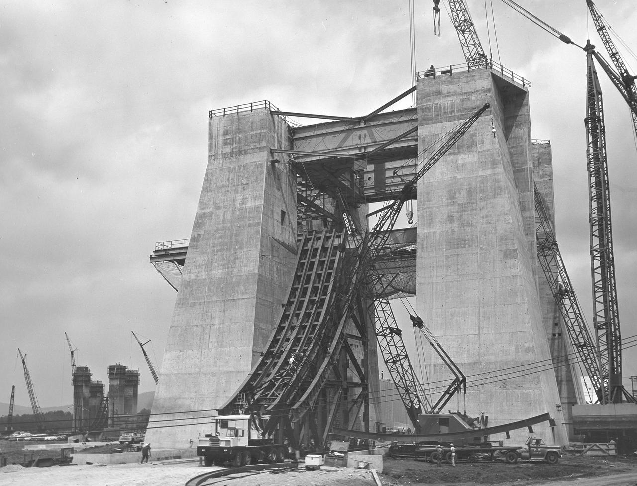
At its founding, the Marshall Space Flight Center (MSFC) inherited the Army’s Jupiter and Redstone test stands, but much larger facilities were needed for the giant stages of the Saturn V. From 1960 to 1964, the existing stands were remodeled and a sizable new test area was developed. The new comprehensive test complex for propulsion and structural dynamics was unique within the nation and the free world, and they remain so today because they were constructed with foresight to meet the future as well as on going needs. Construction of the S-IC Static test stand complex began in 1961 in the west test area of MSFC, and was completed in 1964. The S-IC static test stand was designed to develop and test the 138-ft long and 33-ft diameter Saturn V S-IC first stage, or booster stage, weighing in at 280,000 pounds. Required to hold down the brute force of a 7,500,000-pound thrust produced by 5 F-1 engines, the S-IC static test stand was designed and constructed with the strength of hundreds of tons of steel and 12,000,000 pounds of cement, planted down to bedrock 40 feet below ground level. The foundation walls, constructed with concrete and steel, are 4 feet thick. The base structure consists of four towers with 40-foot-thick walls extending upward 144 feet above ground level. The structure was topped by a crane with a 135-foot boom. With the boom in the upright position, the stand was given an overall height of 405 feet, placing it among the highest structures in Alabama at the time. In addition to the stand itself, related facilities were constructed during this time. Built northeast of the stand was a newly constructed Pump House. Its function was to provide water to the stand to prevent melting damage during testing. The water was sprayed through small holes in the stand’s 1900 ton flame deflector at the rate of 320,000 gallons per minute. In this photo, taken September 5, 1963, the flame deflector is being installed in the S-IC test stand.
At its founding, the Marshall Space Flight Center (MSFC) inherited the Army’s Jupiter and Redstone test stands, but much larger facilities were needed for the giant stages of the Saturn V. From 1960 to 1964, the existing stands were remodeled and a sizable new test area was developed. The new comprehensive test complex for propulsion and structural dynamics was unique within the nation and the free world, and they remain so today because they were constructed with foresight to meet the future as well as on going needs. Construction of the S-IC Static test stand complex began in 1961 in the west test area of MSFC, and was completed in 1964. The S-IC static test stand was designed to develop and test the 138-ft long and 33-ft diameter Saturn V S-IC first stage, or booster stage, weighing in at 280,000 pounds. Required to hold down the brute force of a 7,500,000-pound thrust produced by 5 F-1 engines, the S-IC static test stand was designed and constructed with the strength of hundreds of tons of steel and 12,000,000 pounds of cement, planted down to bedrock 40 feet below ground level. The foundation walls, constructed with concrete and steel, are 4 feet thick. The base structure consists of four towers with 40-foot-thick walls extending upward 144 feet above ground level. The structure was topped by a crane with a 135-foot boom. With the boom in the upright position, the stand was given an overall height of 405 feet, placing it among the highest structures in Alabama at the time. In addition to the stand itself, related facilities were constructed during this time. Built to the northeast of the stand was a newly constructed Pump House. Its function was to provide water to the stand to prevent melting damage during testing. The water was sprayed through small holes in the stand’s 1900 ton flame deflector at the rate of 320,000 gallons per minute. In this photo of the S-IC test stand, taken October 2, 1963, the flame deflector can be seen in the bottom center portion of the stand. The deflector was assembled on tracks for mobility. To the left of the stand are two spherical hydrogen storage tanks.
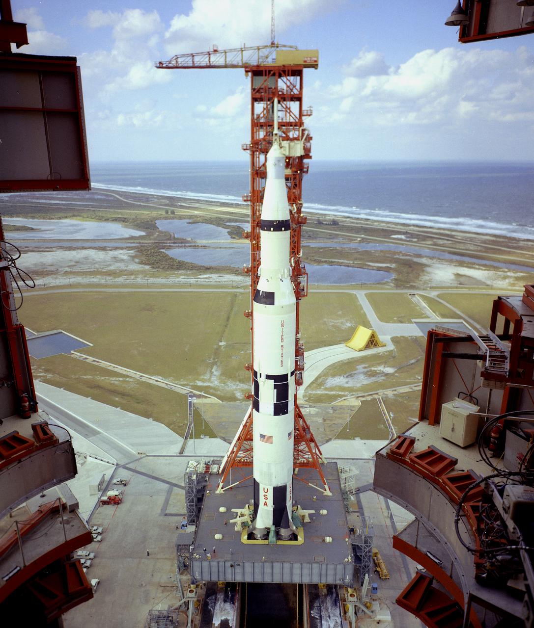
This is a view of the the first test flight of the Saturn V vehicle (SA-501) at the Kennedy Space Center (KSC) launch complex 39A. The thrust chambers of the first stage's five engines extend into the 45-foot-square hole in the mobile launcher platform. Until liftoff, the flames impinged downward onto a flame deflector that diverted the blast lengthwise in the flame trench. Here, a flame deflector, coated with a black ceramic, is in place below the opening, while a yellow (uncoated) spare deflector rests on its track in the background. It took a tremendous flow of water (28,000 gallons per minute) to cool the flame deflector and trench. The Apollo 4 was launched on November 9, 1967 from KSC.
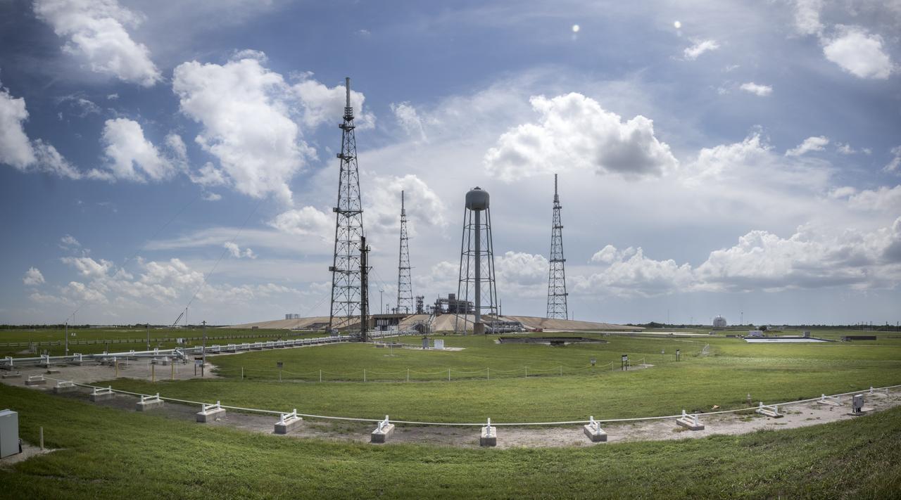
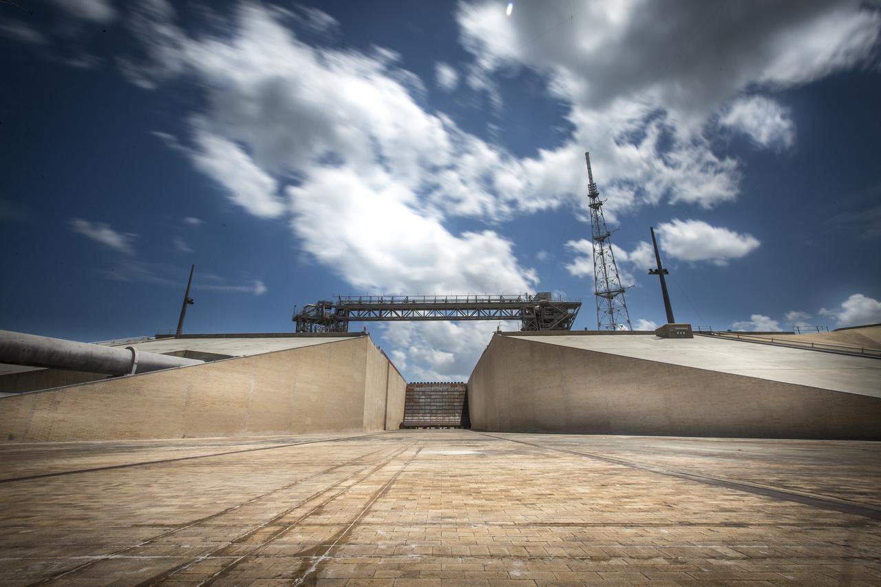
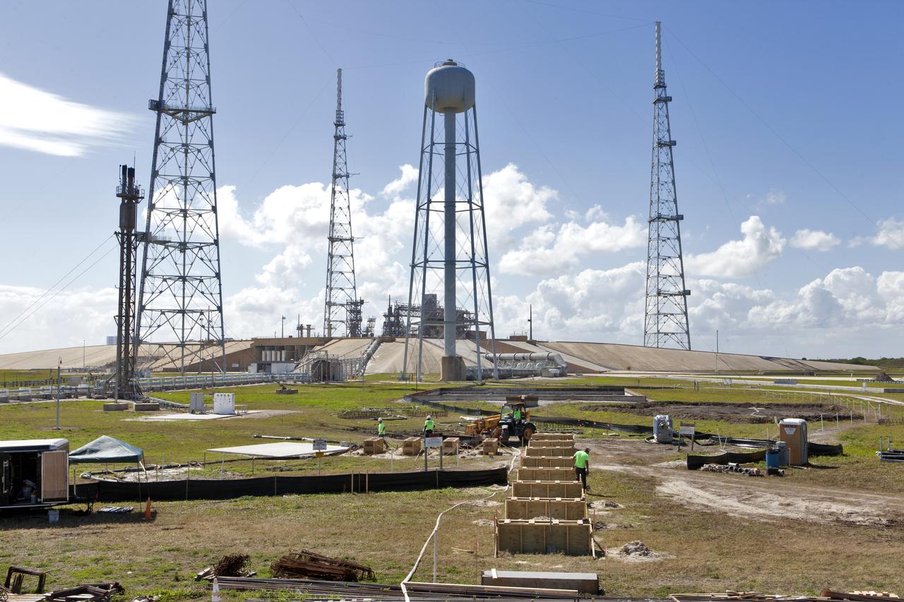
A full view of Launch Pad 39B at NASA's Kennedy Space Center in Florida on July 26, 2018. The launch pad has undergone upgrades and modifications to accommodate NASA's Space Launch System and Orion spacecraft for Exploration Mission-1 and other deep space missions. New heat-resistant bricks have been installed on the walls and a new flame deflector is in place. In view are the three lightning protection system towers and water tank. The clean pad concept is designed to support NASA and commercial launch providers at the multi-user spaceport.
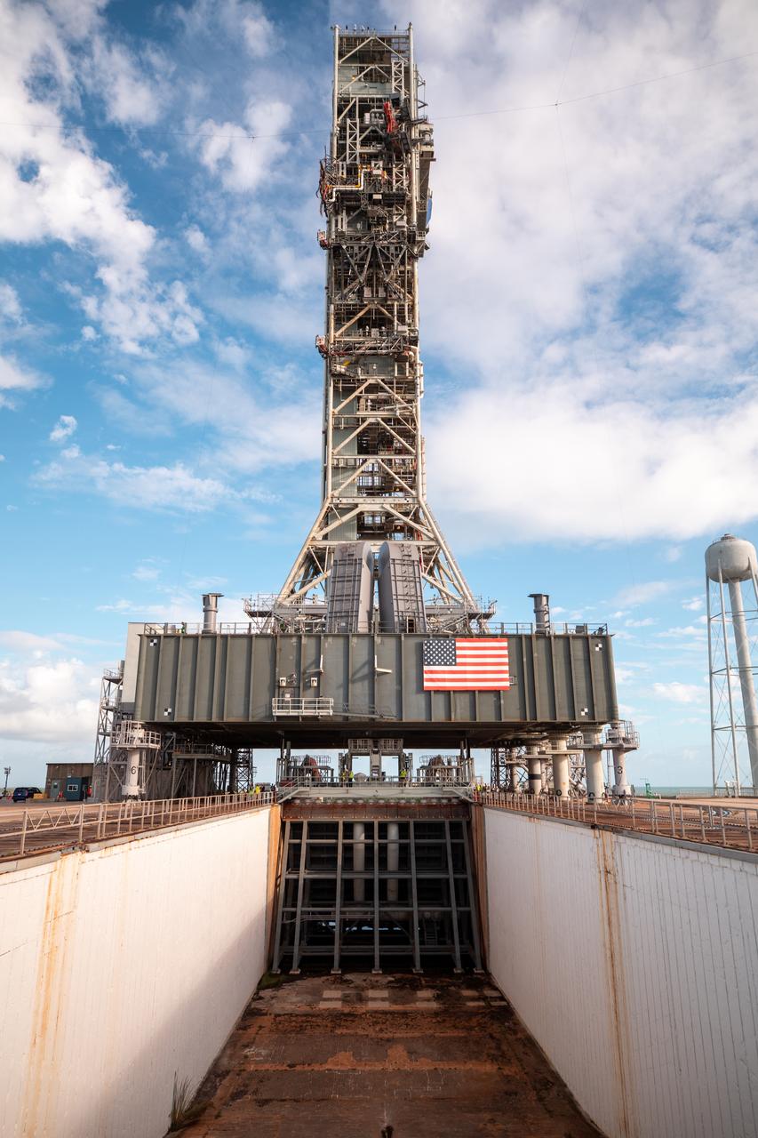
A view of the mobile launcher for the Artemis I mission on Launch Pad 39B at NASA’s Kennedy Space Center in Florida on Oct. 23, 2020. The flame trench and flame deflector are in view below the mobile launcher. The nearly 400-foot-tall mobile launcher will remain at the pad while engineers with Exploration Ground Systems and Jacobs complete several tasks, including a timing test to validate the launch team’s countdown timeline, and a thorough, top-to-bottom wash down of the mobile launcher to remove any debris remaining from construction and installation of the umbilical arms. Artemis I will test the Orion spacecraft and Space Launch System as an integrated system ahead of crewed flights to the Moon. Under the Artemis program, NASA will land the first woman and the next man on the Moon in 2024.
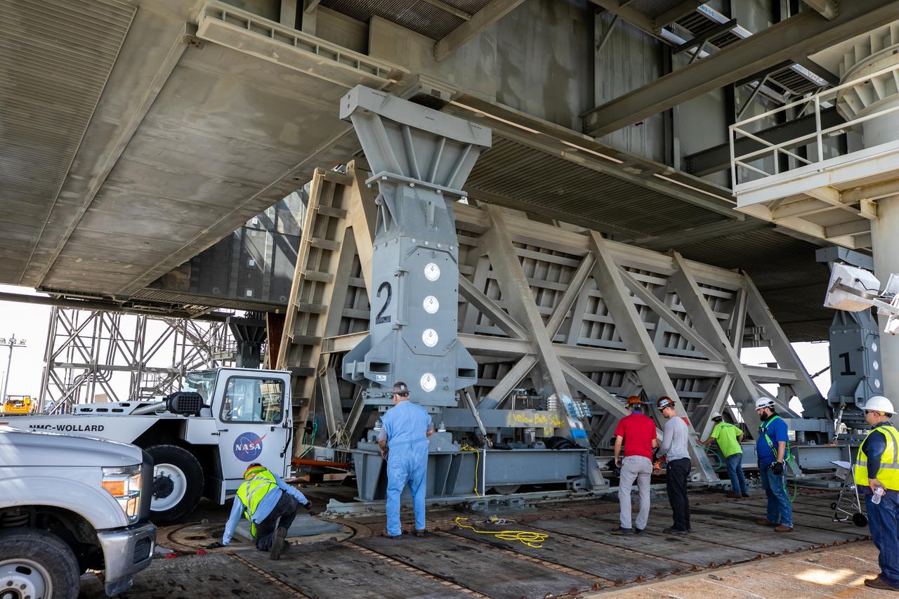
Special ground support equipment is used to position one of two side flame deflectors underneath the mobile launcher for Artemis I during a countdown demonstration test at Launch Pad 39B at NASA’s Kennedy Space Center in Florida on Oct. 23, 2020. The nearly 400-foot-tall mobile launcher is at the pad while engineers with Exploration Ground Systems and Jacobs complete several tasks, including a timing test to validate the launch team’s countdown timeline, and a thorough, top-to-bottom wash down of the mobile launcher to remove any debris remaining from construction and installation of the umbilical arms. Artemis I will test the Orion spacecraft and Space Launch System as an integrated system ahead of crewed flights to the Moon. Under the Artemis program, NASA will land the first woman and the next man on the Moon in 2024.
Special ground support equipment is used to move the side flame deflectors into place during a countdown demonstration test using the mobile launcher for the Artemis I mission at Launch Pad 39B at NASA’s Kennedy Space Center in Florida on Oct. 23, 2020. The nearly 400-foot-tall mobile launcher is at the pad while engineers with Exploration Ground Systems and Jacobs complete several tasks, including a timing test to validate the launch team’s countdown timeline, and a thorough, top-to-bottom wash down of the mobile launcher to remove any debris remaining from construction and installation of the umbilical arms. Artemis I will test the Orion spacecraft and Space Launch System as an integrated system ahead of crewed flights to the Moon. Under the Artemis program, NASA will land the first woman and the next man on the Moon in 2024.
Special ground support equipment is used to move the side flame deflectors into place during a countdown demonstration test using the mobile launcher for the Artemis I mission at Launch Pad 39B at NASA’s Kennedy Space Center in Florida on Oct. 23, 2020. The nearly 400-foot-tall mobile launcher is at the pad while engineers with Exploration Ground Systems and Jacobs complete several tasks, including a timing test to validate the launch team’s countdown timeline, and a thorough, top-to-bottom wash down of the mobile launcher to remove any debris remaining from construction and installation of the umbilical arms. Artemis I will test the Orion spacecraft and Space Launch System as an integrated system ahead of crewed flights to the Moon. Under the Artemis program, NASA will land the first woman and the next man on the Moon in 2024.
Special ground support equipment is used to position the two side flame deflectors underneath the mobile launcher for Artemis I during a countdown demonstration test at Launch Pad 39B at NASA’s Kennedy Space Center in Florida on Oct. 23, 2020. The nearly 400-foot-tall mobile launcher is at the pad while engineers with Exploration Ground Systems and Jacobs complete several tasks, including a timing test to validate the launch team’s countdown timeline, and a thorough, top-to-bottom wash down of the mobile launcher to remove any debris remaining from construction and installation of the umbilical arms. Artemis I will test the Orion spacecraft and Space Launch System as an integrated system ahead of crewed flights to the Moon. Under the Artemis program, NASA will land the first woman and the next man on the Moon in 2024.
Special ground support equipment is used to position the two side flame deflectors underneath the mobile launcher for Artemis I during a countdown demonstration test at Launch Pad 39B at NASA’s Kennedy Space Center in Florida on Oct. 23, 2020. The nearly 400-foot-tall mobile launcher is at the pad while engineers with Exploration Ground Systems and Jacobs complete several tasks, including a timing test to validate the launch team’s countdown timeline, and a thorough, top-to-bottom wash down of the mobile launcher to remove any debris remaining from construction and installation of the umbilical arms. Artemis I will test the Orion spacecraft and Space Launch System as an integrated system ahead of crewed flights to the Moon. Under the Artemis program, NASA will land the first woman and the next man on the Moon in 2024.
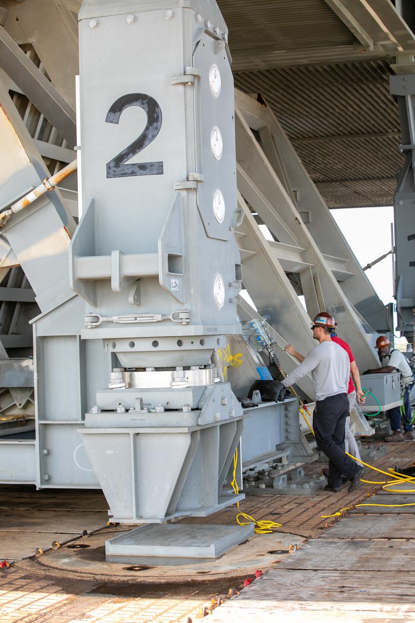
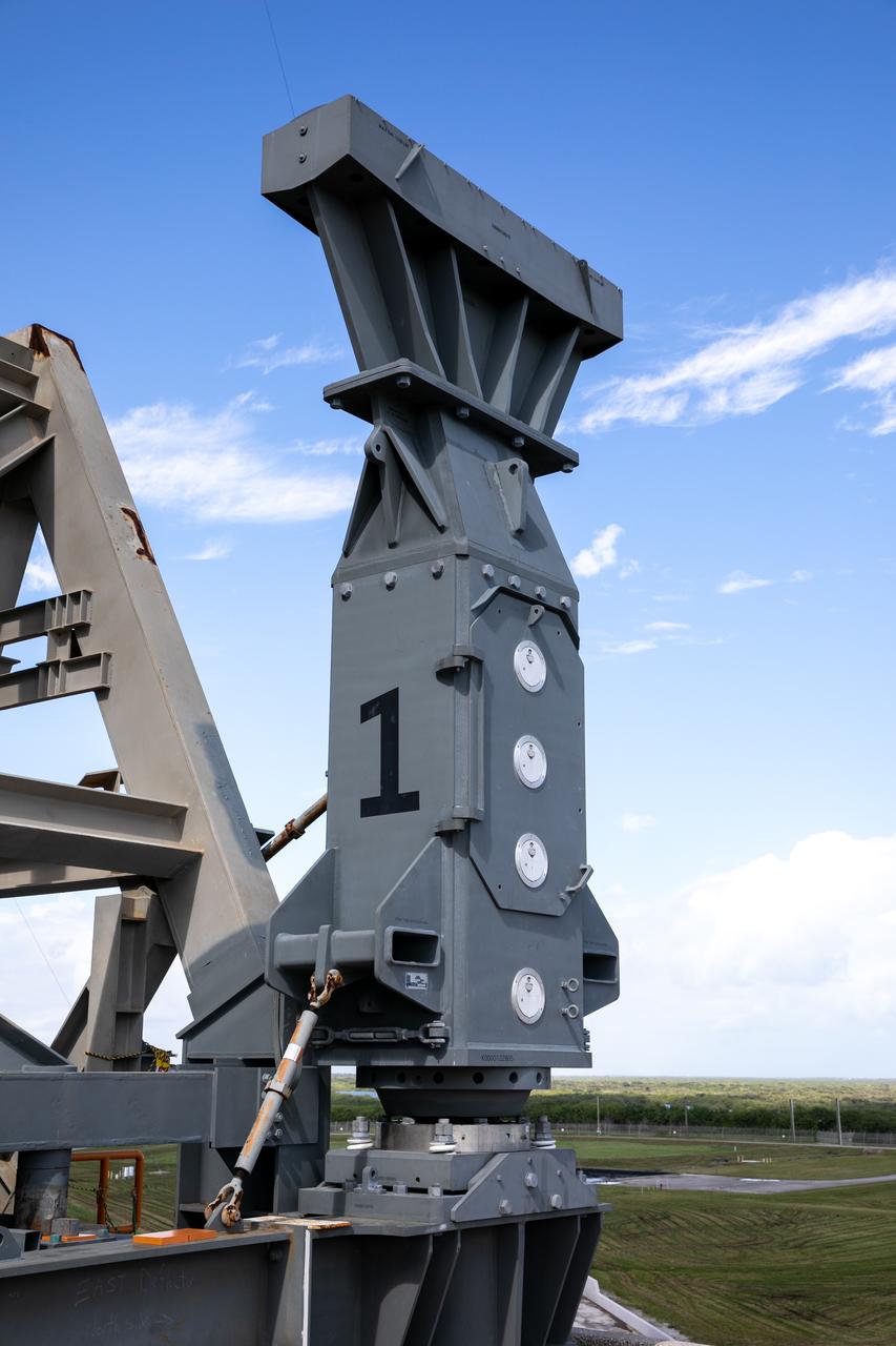
A close-up view of the base of one of the side flame deflectors positioned underneath the mobile launcher for Artemis I during a countdown demonstration test at Launch Pad 39B at NASA’s Kennedy Space Center in Florida on Oct. 23, 2020. The nearly 400-foot-tall mobile launcher is at the pad while engineers with Exploration Ground Systems and Jacobs complete several tasks, including a timing test to validate the launch team’s countdown timeline, and a thorough, top-to-bottom wash down of the mobile launcher to remove any debris remaining from construction and installation of the umbilical arms. Artemis I will test the Orion spacecraft and Space Launch System as an integrated system ahead of crewed flights to the Moon. Under the Artemis program, NASA will land the first woman and the next man on the Moon in 2024.
Technicians help move the side flame deflectors into place during a countdown demonstration test using the mobile launcher for the Artemis I mission at Launch Pad 39B at NASA’s Kennedy Space Center in Florida on Oct. 23, 2020. The nearly 400-foot-tall mobile launcher is at the pad while engineers with Exploration Ground Systems and Jacobs complete several tasks, including a timing test to validate the launch team’s countdown timeline, and a thorough, top-to-bottom wash down of the mobile launcher to remove any debris remaining from construction and installation of the umbilical arms. Artemis I will test the Orion spacecraft and Space Launch System as an integrated system ahead of crewed flights to the Moon. Under the Artemis program, NASA will land the first woman and the next man on the Moon in 2024.

Special ground support equipment is used to move the side flame deflectors into place during a countdown demonstration test using the mobile launcher for the Artemis I mission at Launch Pad 39B at NASA’s Kennedy Space Center in Florida on Oct. 23, 2020. The nearly 400-foot-tall mobile launcher is at the pad while engineers with Exploration Ground Systems and Jacobs complete several tasks, including a timing test to validate the launch team’s countdown timeline, and a thorough, top-to-bottom wash down of the mobile launcher to remove any debris remaining from construction and installation of the umbilical arms. Artemis I will test the Orion spacecraft and Space Launch System as an integrated system ahead of crewed flights to the Moon. Under the Artemis program, NASA will land the first woman and the next man on the Moon in 2024.
Special ground support equipment is used to move one of two side flame deflectors underneath the mobile launcher for Artemis I during a countdown demonstration test at Launch Pad 39B at NASA’s Kennedy Space Center in Florida on Oct. 23, 2020. The nearly 400-foot-tall mobile launcher is at the pad while engineers with Exploration Ground Systems and Jacobs complete several tasks, including a timing test to validate the launch team’s countdown timeline, and a thorough, top-to-bottom wash down of the mobile launcher to remove any debris remaining from construction and installation of the umbilical arms. Artemis I will test the Orion spacecraft and Space Launch System as an integrated system ahead of crewed flights to the Moon. Under the Artemis program, NASA will land the first woman and the next man on the Moon in 2024.
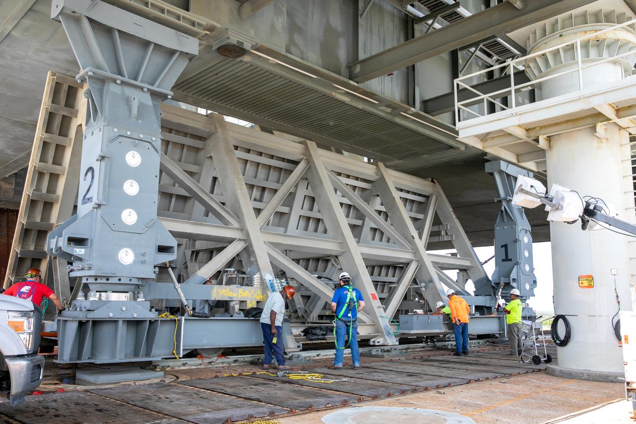
A close-up view of the base of the mobile launcher for Artemis I with the two side flame deflectors positioned underneath during a countdown demonstration test at Launch Pad 39B at NASA’s Kennedy Space Center in Florida on Oct. 23, 2020. The nearly 400-foot-tall mobile launcher is at the pad while engineers with Exploration Ground Systems and Jacobs complete several tasks, including a timing test to validate the launch team’s countdown timeline, and a thorough, top-to-bottom wash down of the mobile launcher to remove any debris remaining from construction and installation of the umbilical arms. Artemis I will test the Orion spacecraft and Space Launch System as an integrated system ahead of crewed flights to the Moon. Under the Artemis program, NASA will land the first woman and the next man on the Moon in 2024.

Special ground support equipment is used to move the side flame deflectors into place during a countdown demonstration test using the mobile launcher for the Artemis I mission at Launch Pad 39B at NASA’s Kennedy Space Center in Florida on Oct. 23, 2020. The nearly 400-foot-tall mobile launcher is at the pad while engineers with Exploration Ground Systems and Jacobs complete several tasks, including a timing test to validate the launch team’s countdown timeline, and a thorough, top-to-bottom wash down of the mobile launcher to remove any debris remaining from construction and installation of the umbilical arms. Artemis I will test the Orion spacecraft and Space Launch System as an integrated system ahead of crewed flights to the Moon. Under the Artemis program, NASA will land the first woman and the next man on the Moon in 2024.
Special ground support equipment is used to move one of two side flame deflectors underneath the mobile launcher for Artemis I during a countdown demonstration test at Launch Pad 39B at NASA’s Kennedy Space Center in Florida on Oct. 23, 2020. The nearly 400-foot-tall mobile launcher is at the pad while engineers with Exploration Ground Systems and Jacobs complete several tasks, including a timing test to validate the launch team’s countdown timeline, and a thorough, top-to-bottom wash down of the mobile launcher to remove any debris remaining from construction and installation of the umbilical arms. Artemis I will test the Orion spacecraft and Space Launch System as an integrated system ahead of crewed flights to the Moon. Under the Artemis program, NASA will land the first woman and the next man on the Moon in 2024.
Special ground support equipment is used to move the side flame deflectors into place during a countdown demonstration test using the mobile launcher for the Artemis I mission at Launch Pad 39B at NASA’s Kennedy Space Center in Florida on Oct. 23, 2020. The nearly 400-foot-tall mobile launcher is at the pad while engineers with Exploration Ground Systems and Jacobs complete several tasks, including a timing test to validate the launch team’s countdown timeline, and a thorough, top-to-bottom wash down of the mobile launcher to remove any debris remaining from construction and installation of the umbilical arms. Artemis I will test the Orion spacecraft and Space Launch System as an integrated system ahead of crewed flights to the Moon. Under the Artemis program, NASA will land the first woman and the next man on the Moon in 2024.
Special ground support equipment is used to position one of two side flame deflectors underneath the mobile launcher for Artemis I during a countdown demonstration test at Launch Pad 39B at NASA’s Kennedy Space Center in Florida on Oct. 23, 2020. The nearly 400-foot-tall mobile launcher is at the pad while engineers with Exploration Ground Systems and Jacobs complete several tasks, including a timing test to validate the launch team’s countdown timeline, and a thorough, top-to-bottom wash down of the mobile launcher to remove any debris remaining from construction and installation of the umbilical arms. Artemis I will test the Orion spacecraft and Space Launch System as an integrated system ahead of crewed flights to the Moon. Under the Artemis program, NASA will land the first woman and the next man on the Moon in 2024.
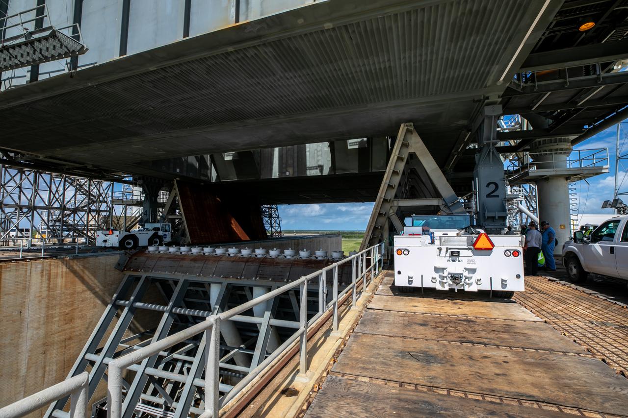
Special ground support equipment is used to move one of two side flame deflectors underneath the mobile launcher for Artemis I during a countdown demonstration test at Launch Pad 39B at NASA’s Kennedy Space Center in Florida on Oct. 23, 2020. The nearly 400-foot-tall mobile launcher is at the pad while engineers with Exploration Ground Systems and Jacobs complete several tasks, including a timing test to validate the launch team’s countdown timeline, and a thorough, top-to-bottom wash down of the mobile launcher to remove any debris remaining from construction and installation of the umbilical arms. Artemis I will test the Orion spacecraft and Space Launch System as an integrated system ahead of crewed flights to the Moon. Under the Artemis program, NASA will land the first woman and the next man on the Moon in 2024.
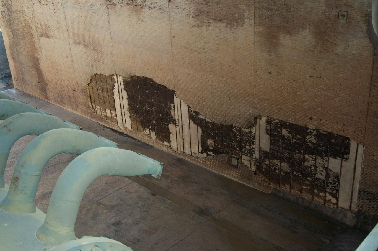
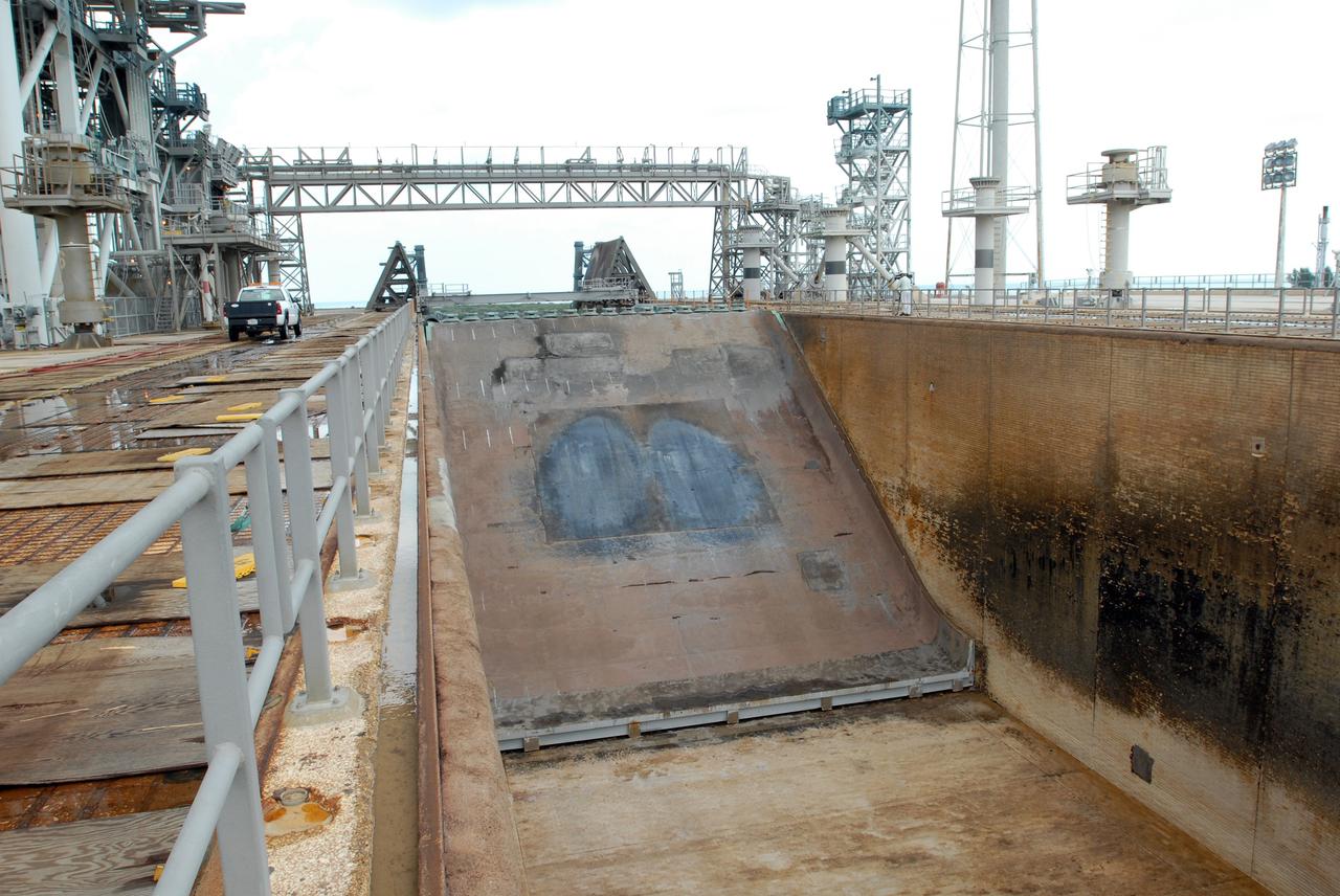
CAPE CANAVERAL, Fla. -- During the post-launch walk down of Launch Pad 39A at NASA's Kennedy Space Center, observers noted severe launch damage on a 100’ X 20’ section of the east wall of the north flame trench (seen here). Broken sections of the flame trench wall were scattered from the flame trench to the pad perimeter fence. NASA is forming an investigation board. The flame trench transecting the pad's mound at ground level is 490 feet long, 58 feet wide and 40 feet high. It is made of concrete and refractory brick. The top of the solid rocket booster flame deflector abuts with that of the orbiter flame deflector to form a flattened, inverted V-shaped structure beneath the mobile launcher platform's three exhaust holes. The orbiter flame deflector is fixed and is 38 feet high, 72 feet long and 57.6 feet wide. The deflector weighs 1.3 million pounds. The solid rocket booster deflector is 42.5 feet high, 42 feet long and 57 feet wide. The structure weighs 1.1 million pounds. The deflectors are built of steel and covered with a high-temperature concrete surface with an average thickness of 5 inches. There are two movable solid rocket booster side flame deflectors, one located on each side of the flame trench. They are 19.5 feet high, 44 feet long and 17.5 feet wide. Photo credit: NASA/Jim Grossmann
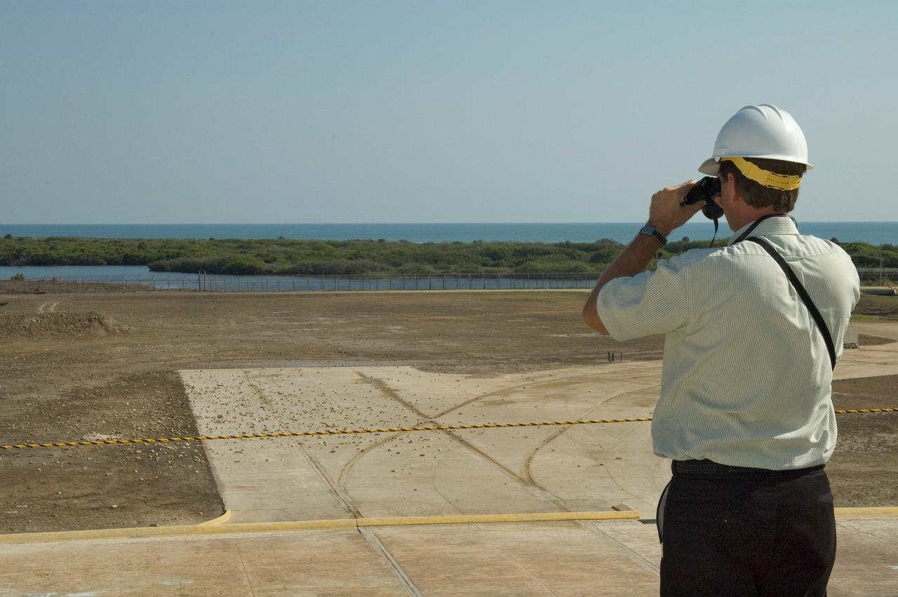
CAPE CANAVERAL, Fla. -- A member of the walk-down team takes a close look at debris scattered across Launch Pad 39A at NASA's Kennedy Space Center following launch of space shuttle Discovery on its STS-124 mission. During the post-launch walk down, the pad team noted severe launch damage on a 100’ X 20’ section of the east wall of the north flame trench. Broken sections of the flame trench wall were scattered from the flame trench to the pad perimeter fence. NASA is forming an investigation board. The flame trench transecting the pad's mound at ground level is 490 feet long, 58 feet wide and 40 feet high. It is made of concrete and refractory brick. The top of the solid rocket booster flame deflector abuts with that of the orbiter flame deflector to form a flattened, inverted V-shaped structure beneath the mobile launcher platform's three exhaust holes. The orbiter flame deflector is fixed and is 38 feet high, 72 feet long and 57.6 feet wide. The deflector weighs 1.3 million pounds. The solid rocket booster deflector is 42.5 feet high, 42 feet long and 57 feet wide. The structure weighs 1.1 million pounds. The deflectors are built of steel and covered with a high-temperature concrete surface with an average thickness of 5 inches. There are two movable solid rocket booster side flame deflectors, one located on each side of the flame trench. They are 19.5 feet high, 44 feet long and 17.5 feet wide. Photo credit: NASA/Jim Grossmann
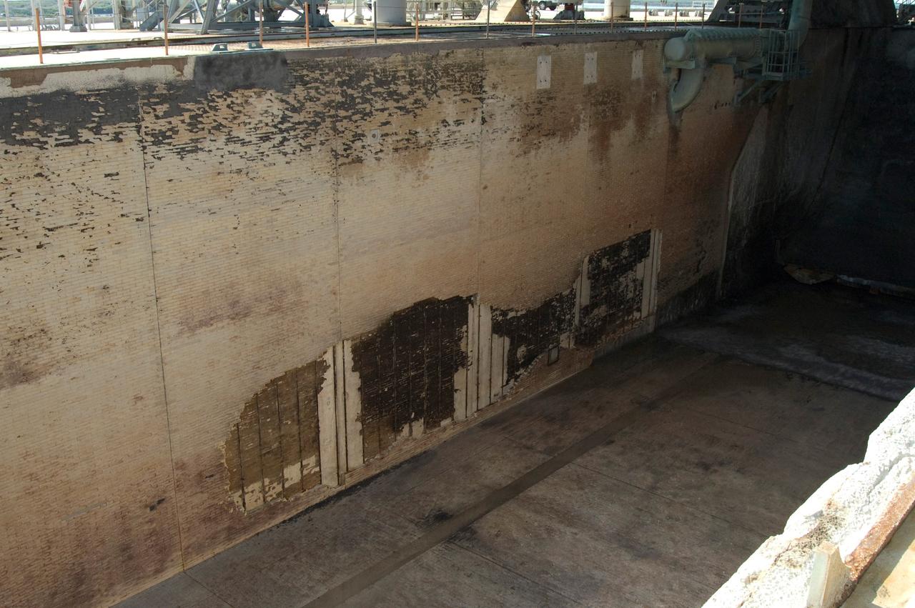
CAPE CANAVERAL, Fla. -- During the post-launch walk down of Launch Pad 39A at NASA's Kennedy Space Center, the pad team noted severe launch damage on a 100’ X 20’ section of the east wall of the north flame trench (seen here). Broken sections of the flame trench wall were scattered from the flame trench to the pad perimeter fence. NASA is forming an investigation board. The flame trench transecting the pad's mound at ground level is 490 feet long, 58 feet wide and 40 feet high. It is made of concrete and refractory brick. The top of the solid rocket booster flame deflector abuts with that of the orbiter flame deflector to form a flattened, inverted V-shaped structure beneath the mobile launcher platform's three exhaust holes. The orbiter flame deflector is fixed and is 38 feet high, 72 feet long and 57.6 feet wide. The deflector weighs 1.3 million pounds. The solid rocket booster deflector is 42.5 feet high, 42 feet long and 57 feet wide. The structure weighs 1.1 million pounds. The deflectors are built of steel and covered with a high-temperature concrete surface with an average thickness of 5 inches. There are two movable solid rocket booster side flame deflectors, one located on each side of the flame trench. They are 19.5 feet high, 44 feet long and 17.5 feet wide. Photo credit: NASA/Jim Grossmann
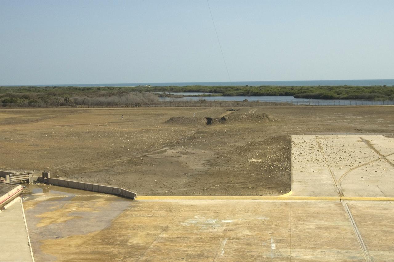
CAPE CANAVERAL, Fla. -- Debris is scattered across Launch Pad 39A at NASA's Kennedy Space Center following launch of space shuttle Discovery on its STS-124 mission. During the post-launch walk down, the pad team noted severe launch damage on a 100’ X 20’ section of the east wall of the north flame trench. Broken sections of the flame trench wall were scattered from the flame trench to the pad perimeter fence. NASA is forming an investigation board. The flame trench transecting the pad's mound at ground level is 490 feet long, 58 feet wide and 40 feet high. It is made of concrete and refractory brick. The top of the solid rocket booster flame deflector abuts with that of the orbiter flame deflector to form a flattened, inverted V-shaped structure beneath the mobile launcher platform's three exhaust holes. The orbiter flame deflector is fixed and is 38 feet high, 72 feet long and 57.6 feet wide. The deflector weighs 1.3 million pounds. The solid rocket booster deflector is 42.5 feet high, 42 feet long and 57 feet wide. The structure weighs 1.1 million pounds. The deflectors are built of steel and covered with a high-temperature concrete surface with an average thickness of 5 inches. There are two movable solid rocket booster side flame deflectors, one located on each side of the flame trench. They are 19.5 feet high, 44 feet long and 17.5 feet wide. Photo credit: NASA/Jim Grossmann

At its founding, the Marshall Space Flight Center (MSFC) inherited the Army’s Jupiter and Redstone test stands, but much larger facilities were needed for the giant stages of the Saturn V. From 1960 to 1964, the existing stands were remodeled and a sizable new test area was developed. The new comprehensive test complex for propulsion and structural dynamics was unique within the nation and the free world, and they remain so today because they were constructed with foresight to meet the future as well as on going needs. Construction of the S-IC Static test stand complex began in 1961 in the west test area of MSFC, and was completed in 1964. The S-IC static test stand was originally designed to develop and test the 138-ft long and 33-ft diameter Saturn V S-IC first stage, or booster stage. Modifications to the S-IC Test Stand began in 1975 to accommodate space shuttle external tank testing. This photo depicts the removal of the flame deflector which was originally used to provide water to the 5 F-1 engines of the S-IC stage during testing.

At its founding, the Marshall Space Flight Center (MSFC) inherited the Army’s Jupiter and Redstone test stands, but much larger facilities were needed for the giant stages of the Saturn V. From 1960 to 1964, the existing stands were remodeled and a sizable new test area was developed. The new comprehensive test complex for propulsion and structural dynamics was unique within the nation and the free world, and they remain so today because they were constructed with foresight to meet the future as well as on going needs. Construction of the S-IC Static test stand complex began in 1961 in the west test area of MSFC, and was completed in 1964. The S-IC static test stand was originally designed to develop and test the 138-ft long and 33-ft diameter Saturn V S-IC first stage, or booster stage. Modifications to the S-IC Test Stand began in 1975 to accommodate space shuttle external tank testing. This photo depicts the removal of the flame deflector which was originally used to provide water to the 5 F-1 engines of the S-IC stage during testing.
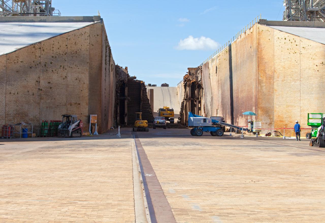
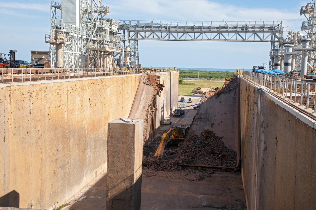
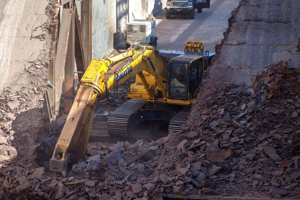
CAPE CANAVERAL, Fla. – A construction crew uses heavy machinery to take apart the flame deflector at Launch Complex 39B as the flame trench is refurbished for future rocket launches at NASA's Kennedy Space Center in Florida. Photo credit: NASA/Daniel Casper
CAPE CANAVERAL, Fla. – A construction crew uses heavy machinery to take apart the flame deflector at Launch Complex 39B as the flame trench is refurbished for future rocket launches at NASA's Kennedy Space Center in Florida. Photo credit: NASA/Daniel Casper
CAPE CANAVERAL, Fla. – A construction crew uses heavy machinery to take apart the flame deflector at Launch Complex 39B as the flame trench is refurbished for future rocket launches at NASA's Kennedy Space Center in Florida. Photo credit: NASA/Daniel Casper
CAPE CANAVERAL, Fla. – A construction crew uses heavy machinery to take apart the flame deflector at Launch Complex 39B as the flame trench is refurbished for future rocket launches at NASA's Kennedy Space Center in Florida. Photo credit: NASA/Daniel Casper
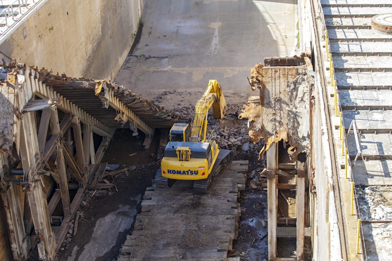
CAPE CANAVERAL, Fla. – A construction crew uses heavy machinery to take apart the flame deflector at Launch Complex 39B as the flame trench is refurbished for future rocket launches at NASA's Kennedy Space Center in Florida. Photo credit: NASA/Daniel Casper
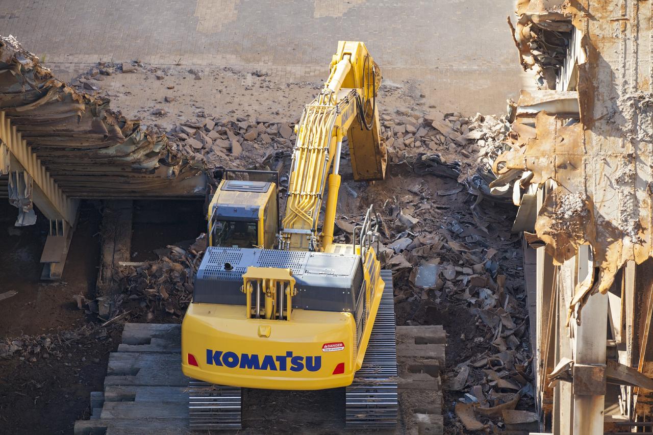
CAPE CANAVERAL, Fla. – A construction crew uses heavy machinery to take apart the flame deflector at Launch Complex 39B as the flame trench is refurbished for future rocket launches at NASA's Kennedy Space Center in Florida. Photo credit: NASA/Daniel Casper
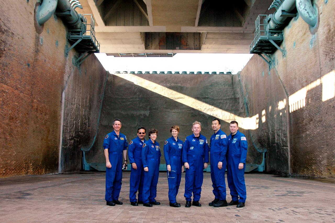
KENNEDY SPACE CENTER, FLA. - During a walkdown of Launch Pad 39B, the STS-114 crew pauses for a photograph in the flame trench underneath the pad. The flame trench, built with concrete and refractory brick, bisects the pad at ground level. It is 490 feet long, 58 feet wide and 42 feet deep. The flame deflector system includes an inverted, V-shaped steel structure covered with a high-temperature concrete material five inches thick that extends across the center of the flame trench. One side of the “V” receives and deflects the flames from the Orbiter main engines; the opposite side deflects the flames from the Solid Rocket Boosters. There are also two movable deflectors at the top of the trench to provide additional protection to Shuttle hardware from the Solid Rocket Booster flames. STS-114 is designated the first Return to Flight mission, with a launch window extending from July 13 to July 31. The crew is at KSC for Terminal Countdown Demonstration Test (TCDT) activities. The TCDT is held at KSC prior to each Space Shuttle flight. It provides the crew of each mission an opportunity to participate in simulated countdown activities. The test ends with a mock launch countdown culminating in a simulated main engine cutoff. The crew also spends time undergoing emergency egress training exercises at the launch pad.
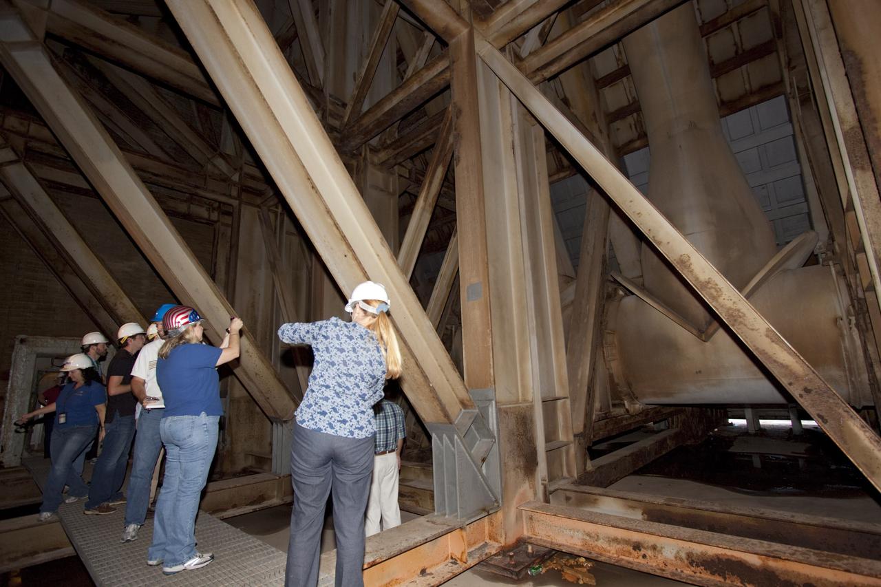
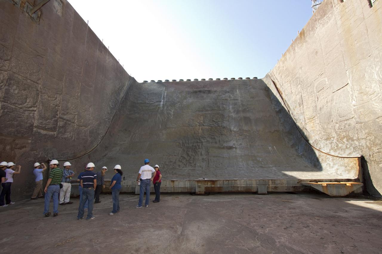
CAPE CANAVERAL, Fla. – Mechanical engineering students from Louisiana State University joined engineers and scientists at Launch Pad 39B at NASA's Kennedy Space Center in Florida as the students toured the facility to have a look at the flame trench. They went inside the pad structure to the area inside the flame deflector which divides the flame trench and funnels exhaust away from a shuttle at liftoff. The flame deflector, which is about 40-feet tall, is essentially hollow inside and braced by steel beams. The students signed up to help designers looking for new, flame and vibration-resistant materials to line the trench. The students are to build a scaled-down version of the flame trench that Kennedy's scientists can use to try out sample materials for the trench. If the samples work in the lab, they can be tried out in the real flame trenches at Launch Pad 39A and 39B. The launch pad has been refurbished extensively and work is continuing to modify the pad to support a variety of launch vehicles in the future. Photo credit: NASA/Jim Grossmann
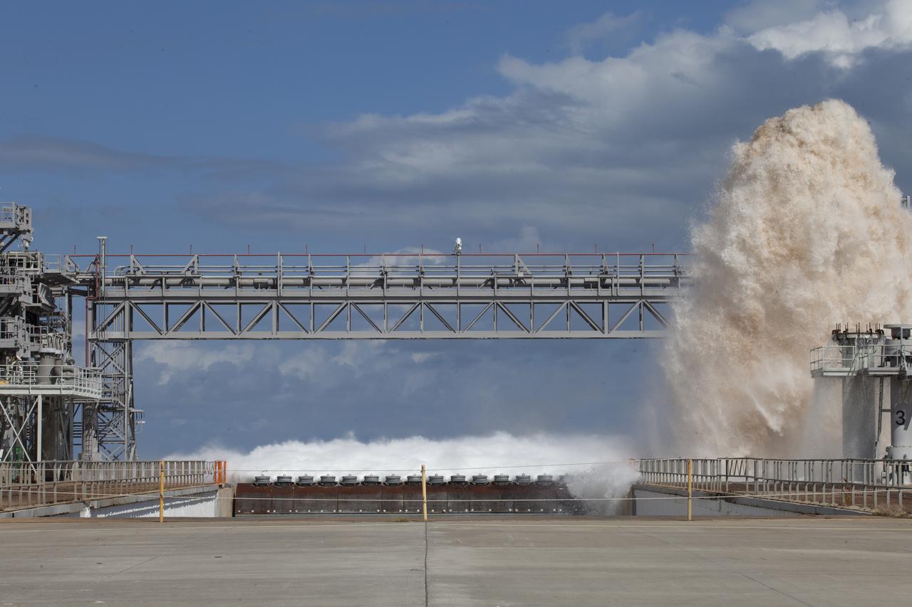
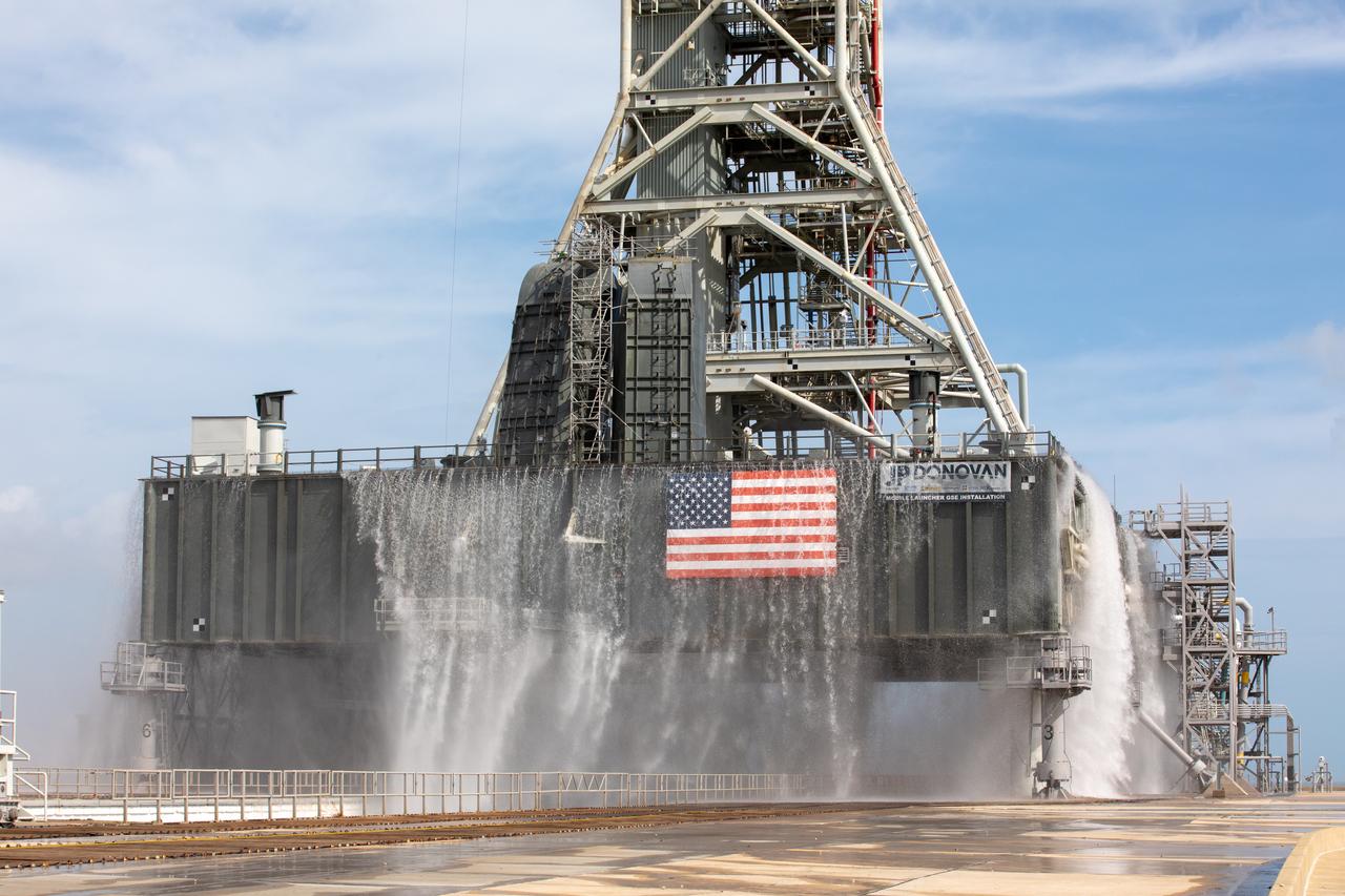
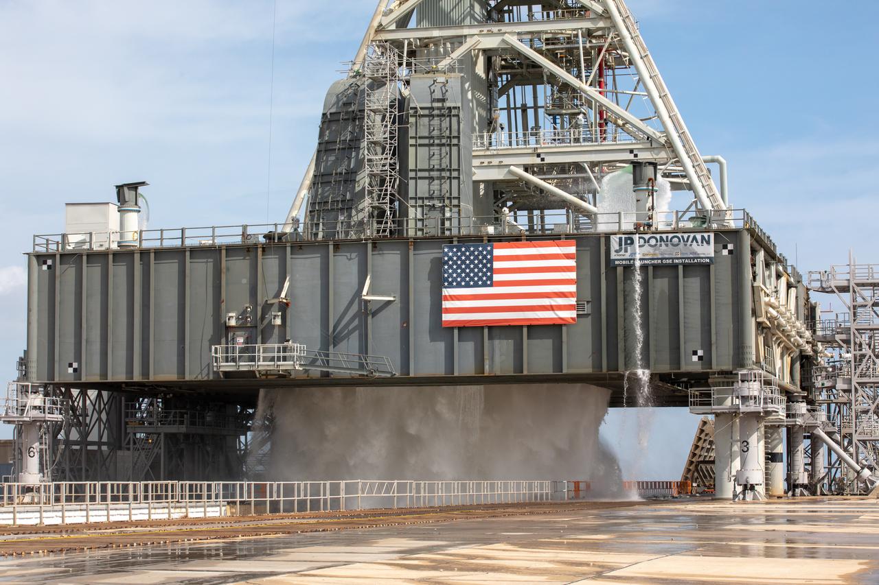
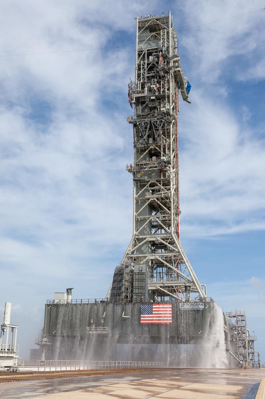
A flow test of the Ignition Overpressure Protection and Sound Suppression water deluge system is in progress at Launch Pad 39B at NASA's Kennedy Space Center in Florida, on Oct. 15, 2018. At peak flow, the water reaches about 100 feet in the air above the pad surface. It flows at high speed from a holding tank through new and modified piping and valves, the flame trench, flame deflector nozzles and mobile launcher interface risers. The testing is part of Exploration Ground System's preparation for the new Space Launch System rocket. Modifications were made to the pad after a previous wet flow test, increasing the performance of the system. During the launch of Exploration Mission-1 and subsequent missions, this water deluge system will release about 450,000 gallons of water across the mobile launcher and Flame Deflector to reduce the extreme heat and energy generated by the rocket during ignition and liftoff.
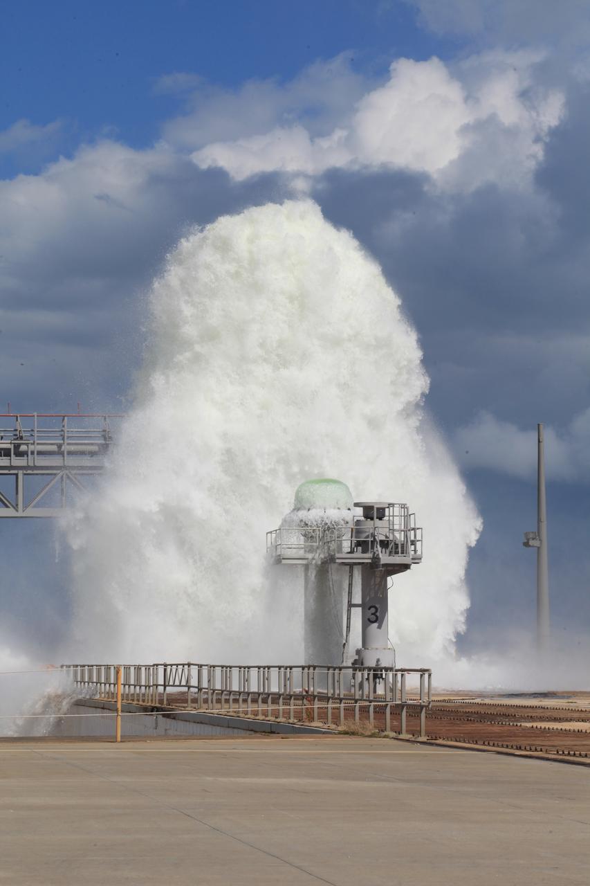
A flow test of the Ignition Overpressure Protection and Sound Suppression water deluge system is in progress at Launch Pad 39B at NASA's Kennedy Space Center in Florida, on Oct. 15, 2018. At peak flow, the water reaches about 100 feet in the air above the pad surface. It flows at high speed from a holding tank through new and modified piping and valves, the flame trench, flame deflector nozzles and mobile launcher interface risers. The testing is part of Exploration Ground System's preparation for the new Space Launch System rocket. Modifications were made to the pad after a previous wet flow test, increasing the performance of the system. During the launch of Exploration Mission-1 and subsequent missions, this water deluge system will release about 450,000 gallons of water across the mobile launcher and Flame Deflector to reduce the extreme heat and energy generated by the rocket during ignition and liftoff.

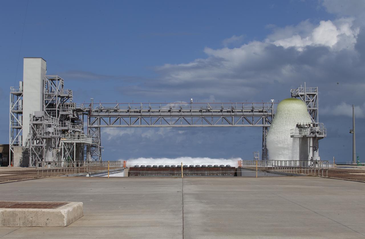
A flow test of the Ignition Overpressure Protection and Sound Suppression water deluge system is in progress at Launch Pad 39B at NASA's Kennedy Space Center in Florida, on Oct. 15, 2018. At peak flow, the water reaches about 100 feet in the air above the pad surface. It flows at high speed from a holding tank through new and modified piping and valves, the flame trench, flame deflector nozzles and mobile launcher interface risers. The testing is part of Exploration Ground System's preparation for the new Space Launch System rocket. Modifications were made to the pad after a previous wet flow test, increasing the performance of the system. During the launch of Exploration Mission-1 and subsequent missions, this water deluge system will release about 450,000 gallons of water across the mobile launcher and Flame Deflector to reduce the extreme heat and energy generated by the rocket during ignition and liftoff.

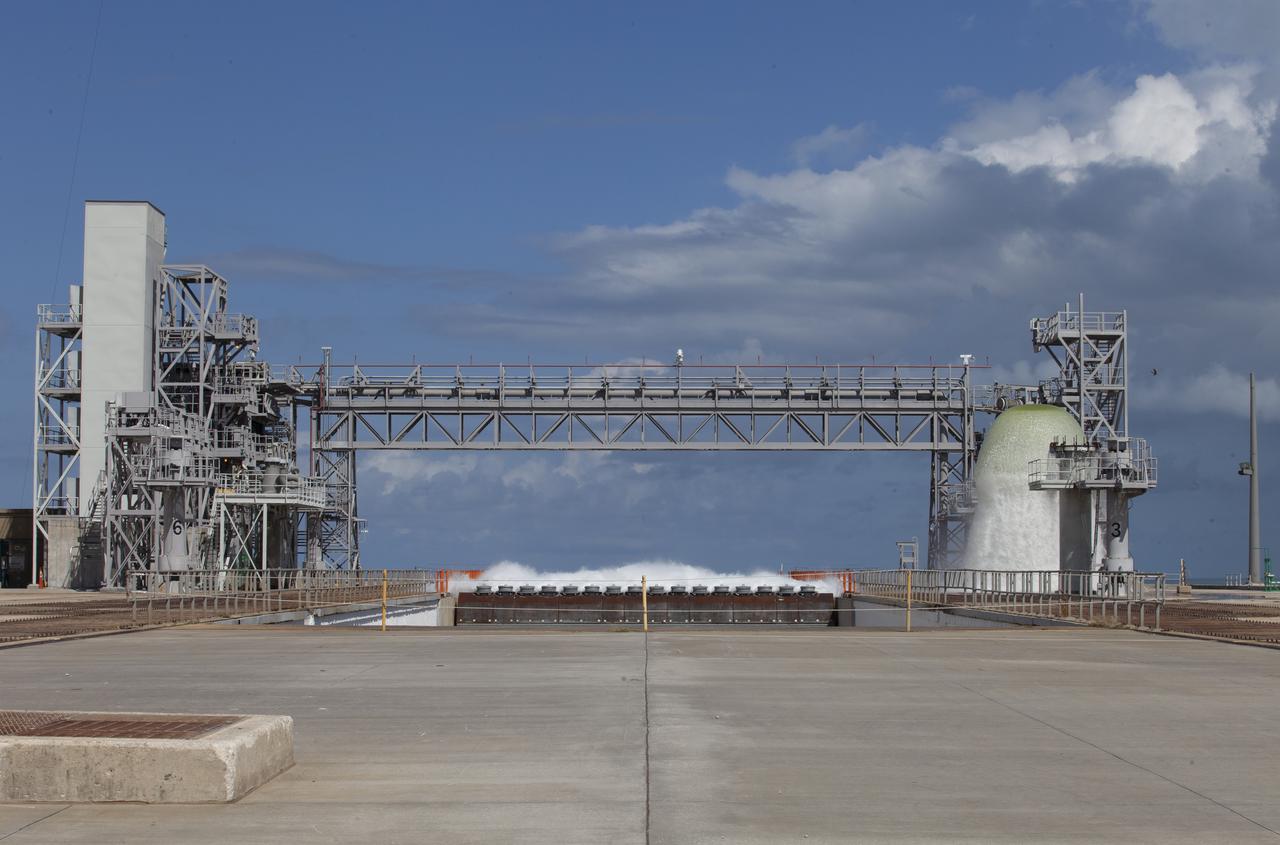
A flow test of the Ignition Overpressure Protection and Sound Suppression water deluge system is in progress at Launch Pad 39B at NASA's Kennedy Space Center in Florida, on Oct. 15, 2018. At peak flow, the water reaches about 100 feet in the air above the pad surface. It flows at high speed from a holding tank through new and modified piping and valves, the flame trench, flame deflector nozzles and mobile launcher interface risers. The testing is part of Exploration Ground System's preparation for the new Space Launch System rocket. Modifications were made to the pad after a previous wet flow test, increasing the performance of the system. During the launch of Exploration Mission-1 and subsequent missions, this water deluge system will release about 450,000 gallons of water across the mobile launcher and Flame Deflector to reduce the extreme heat and energy generated by the rocket during ignition and liftoff.
A flow test of the Ignition Overpressure Protection and Sound Suppression water deluge system is in progress at Launch Pad 39B at NASA's Kennedy Space Center in Florida, on Oct. 15, 2018. At peak flow, the water will reach about 100 feet in the air above the pad surface. It will flow at high speed from a holding tank through new and modified piping and valves, the flame trench, flame deflector nozzles and mobile launcher interface risers. The testing is part of Exploration Ground System's preparation for the new Space Launch System rocket. Modifications were made to the pad after a previous wet flow test, increasing the performance of the system. During the launch of Exploration Mission-1 and subsequent missions, this water deluge system will release about 450,000 gallons of water across the mobile launcher and Flame Deflector to reduce the extreme heat and energy generated by the rocket during ignition and liftoff.

A flow test of the Ignition Overpressure Protection and Sound Suppression water deluge system is in progress at Launch Pad 39B at NASA's Kennedy Space Center in Florida, on Oct. 15, 2018. At peak flow, the water reaches about 100 feet in the air above the pad surface. It flows at high speed from a holding tank through new and modified piping and valves, the flame trench, flame deflector nozzles and mobile launcher interface risers. The testing is part of Exploration Ground System's preparation for the new Space Launch System rocket. Modifications were made to the pad after a previous wet flow test, increasing the performance of the system. During the launch of Exploration Mission-1 and subsequent missions, this water deluge system will release about 450,000 gallons of water across the mobile launcher and Flame Deflector to reduce the extreme heat and energy generated by the rocket during ignition and liftoff.

A flow test of the Ignition Overpressure Protection and Sound Suppression water deluge system is in progress at Launch Pad 39B at NASA's Kennedy Space Center in Florida, on Oct. 15, 2018. At peak flow, the water reaches about 100 feet in the air above the pad surface. It flows at high speed from a holding tank through new and modified piping and valves, the flame trench, flame deflector nozzles and mobile launcher interface risers. The testing is part of Exploration Ground System's preparation for the new Space Launch System rocket. Modifications were made to the pad after a previous wet flow test, increasing the performance of the system. During the launch of Exploration Mission-1 and subsequent missions, this water deluge system will release about 450,000 gallons of water across the mobile launcher and Flame Deflector to reduce the extreme heat and energy generated by the rocket during ignition and liftoff.
A flow test of the Ignition Overpressure Protection and Sound Suppression water deluge system begins at Launch Pad 39B at NASA's Kennedy Space Center in Florida, on Oct. 15, 2018. At peak flow, the water will reach about 100 feet in the air above the pad surface. It will flow at high speed from a holding tank through new and modified piping and valves, the flame trench, flame deflector nozzles and mobile launcher interface risers. The testing is part of Exploration Ground System's preparation for the new Space Launch System rocket. Modifications were made to the pad after a previous wet flow test, increasing the performance of the system. During the launch of Exploration Mission-1 and subsequent missions, this water deluge system will release about 450,000 gallons of water across the mobile launcher and Flame Deflector to reduce the extreme heat and energy generated by the rocket during ignition and liftoff.
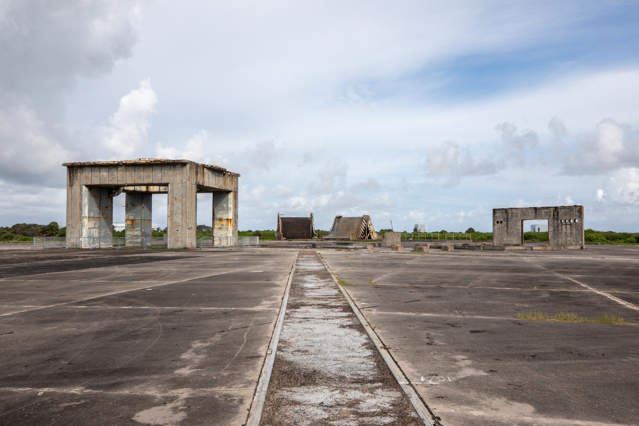
A view of the launch pedestal (at left) still standing at Launch Complex 34 at Cape Canaveral Space Force Station in Florida on July 22, 2020. In the background are two flame deflectors. Work will soon begin to perform environmental contamination removal on the pedestal and the ground area surrounding the launch complex.
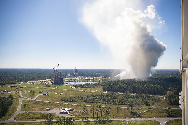
The RS-25 certification test series begins Oct. 17. When the liquid hydrogen and liquid oxygen propellants mix and ignite, an extremely high temperature exhaust, of up to 6,000-degrees Fahrenheit, mixes with water to form steam that exits the flame deflector and rises into the atmosphere, forming a cloud that subsequently cools.
KENNEDY SPACE CENTER, FLA. -- An aerial view of early construction of Launch Pad 39A, looking southwest. Pad 39A is one of two launch sites for the Apollo Saturn V Moon rocket. Each site is an eight-sided polygon and 3,000 feet across. The pad is 390 feet by 325 feet reinforced concrete hardstand standing 48 feet above sea level. The flame trench in the center holds a 700,000-pound flame deflector during launch operations.
Constructions workers are busy repairing the concrete on the surface of Launch Pad 39B at NASA’s Kennedy Space Center in Florida on Feb. 22, 2019. The launch pad has undergone upgrades and modifications to accommodate NASA's Space Launch System and Orion spacecraft for Exploration Mission-1 and subsequent missions. Upgrades include new heat-resistant bricks on the walls of the flame trench and installation of a new flame deflector. All of the upgrades have been managed by Exploration Ground Systems.
Construction workers stage parts and equipment nearby Launch Pad 39B at NASA’s Kennedy Space Center in Florida on Feb. 22, 2019. The launch pad has undergone upgrades and modifications to accommodate NASA's Space Launch System and Orion spacecraft for Exploration Mission-1 and subsequent missions. Upgrades include new heat-resistant bricks on the walls of the flame trench and installation of a new flame deflector. All of the upgrades have been managed by Exploration Ground Systems.
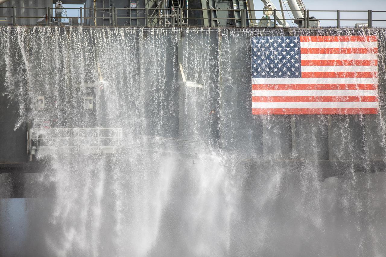
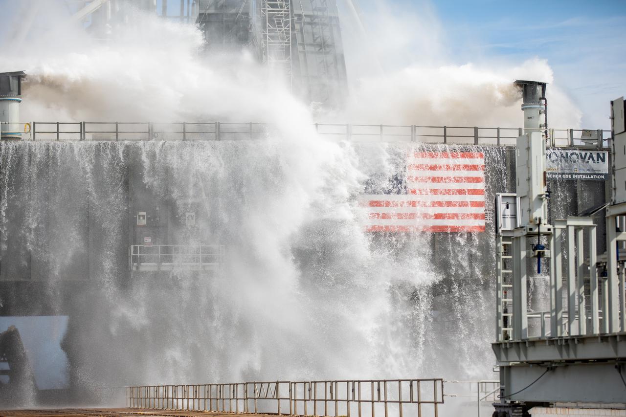
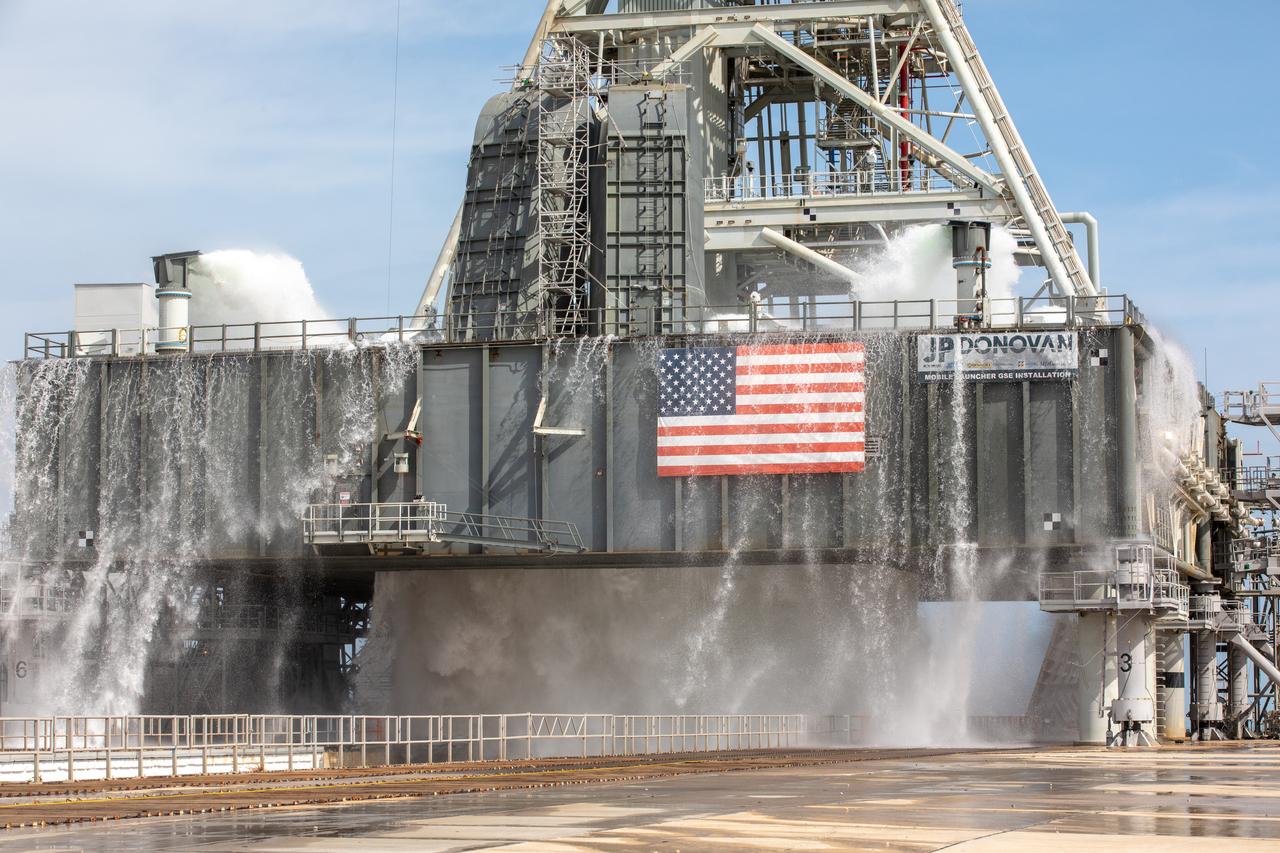
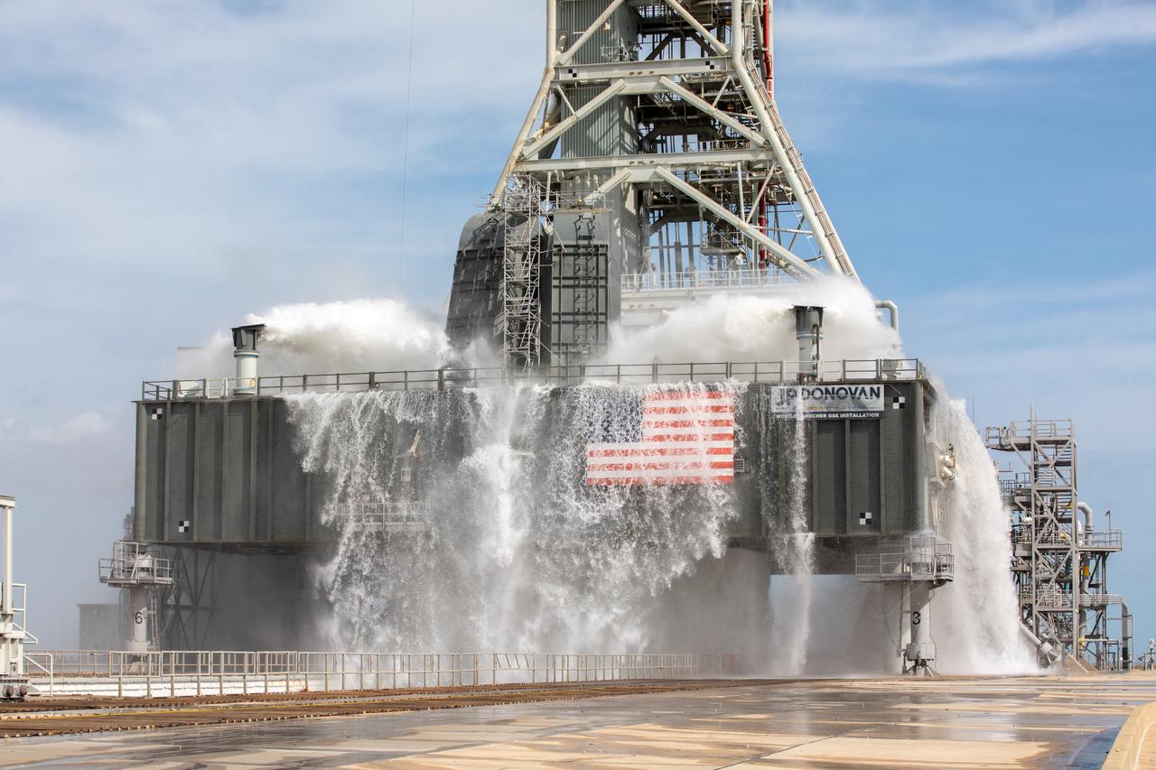
A wet flow test at Launch Pad 39B on September 13, 2019, tests the sound suppression system that will be used for launch of NASA’s Space Launch System for the Artemis I mission. During the test, about 450,000 gallons of water poured onto the Pad B flame deflector, the mobile launcher flame hole and onto the launcher’s blast deck. This was the first time the ground launch sequencer that will be used on the day of launch was used for the timing of a sound suppression test.
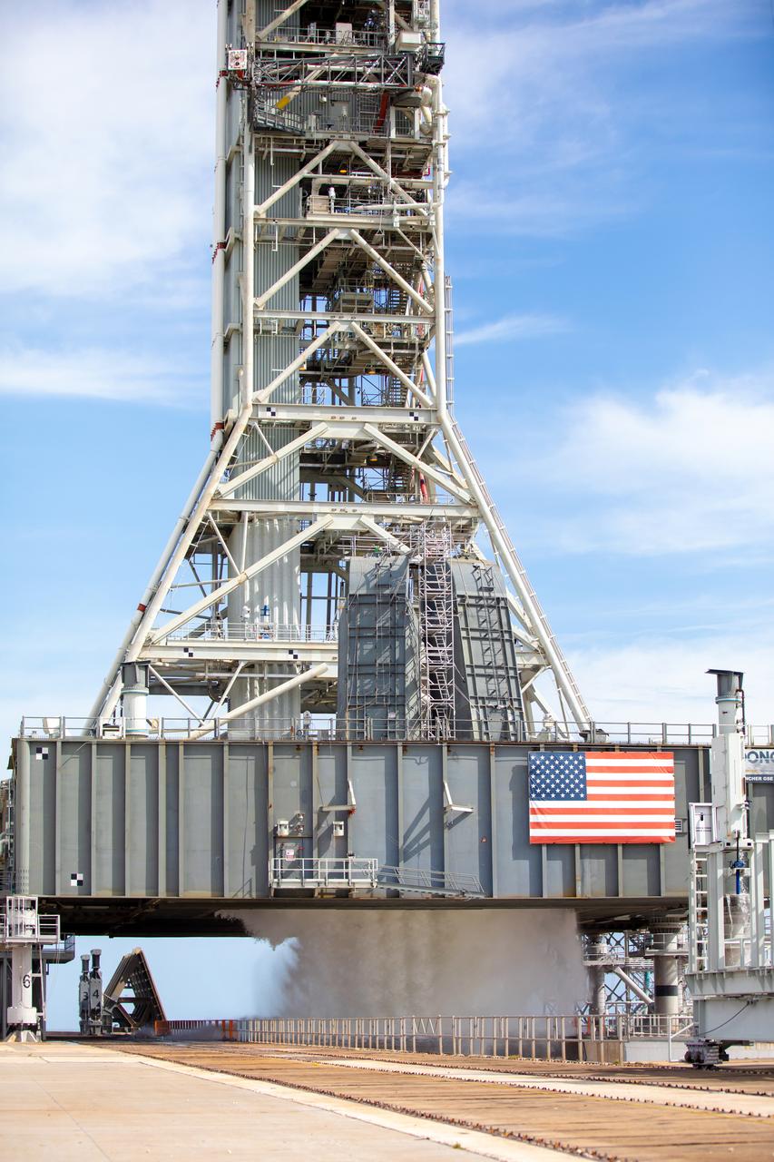
A wet flow test at Launch Pad 39B on September 13, 2019, tests the sound suppression system that will be used for launch of NASA’s Space Launch System for the Artemis I mission. During the test, about 450,000 gallons of water poured onto the Pad B flame deflector, the mobile launcher flame hole and onto the launcher’s blast deck. This was the first time the ground launch sequencer that will be used on the day of launch was used for the timing of a sound suppression test.
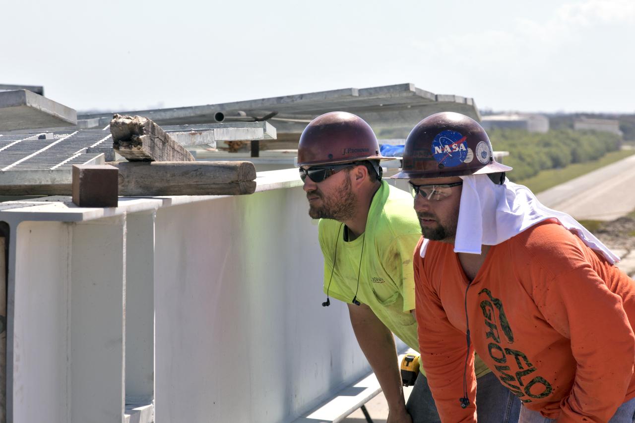
Construction workers assess the repairs needed on the surface of Launch Pad 39B at NASA’s Kennedy Space Center in Florida on Feb. 22, 2019. The launch pad has undergone upgrades and modifications to accommodate NASA's Space Launch System and Orion spacecraft for Exploration Mission-1 and subsequent missions. Upgrades include new heat-resistant bricks on the walls of the flame trench and installation of a new flame deflector. All of the upgrades have been managed by Exploration Ground Systems.
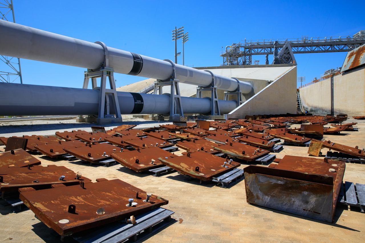
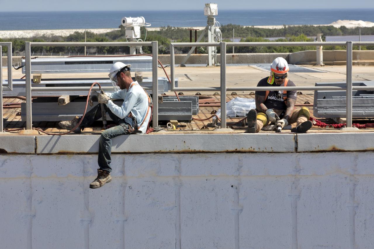
Teams with Exploration Ground Systems at NASA’s Kennedy Space Center in Florida continue to work the upgrades and repairs on mobile launcher 1 and Launch Pad 39B on June 13, 2023, ahead of the first critical ground testing for Artemis II. Teams are re-designing the panels on the flame deflector in the flame trench that withstood damage observed after launch of Artemis I. Artemis II will be the first Artemis mission flying crew aboard Orion.
Teams with Exploration Ground Systems at NASA’s Kennedy Space Center in Florida continue to work the upgrades and repairs on mobile launcher 1 and Launch Pad 39B on June 13, 2023, ahead of the first critical ground testing for Artemis II. Teams are re-designing the panels on the flame deflector in the flame trench that withstood damage observed after launch of Artemis I. Artemis II will be the first Artemis mission flying crew aboard Orion.
Construction workers stage parts and equipment nearby Launch Pad 39B at NASA’s Kennedy Space Center in Florida on Feb. 22, 2019. The launch pad has undergone upgrades and modifications to accommodate NASA's Space Launch System and Orion spacecraft for Exploration Mission-1 and subsequent missions. Upgrades include new heat-resistant bricks on the walls of the flame trench and installation of a new flame deflector. All of the upgrades have been managed by Exploration Ground Systems.
A wet flow test at Launch Pad 39B on September 13, 2019, tests the sound suppression system that will be used for launch of NASA’s Space Launch System for the Artemis I mission. During the test, about 450,000 gallons of water poured onto the Pad B flame deflector, the mobile launcher flame hole and onto the launcher’s blast deck. This was the first time the ground launch sequencer that will be used on the day of launch was used for the timing of a sound suppression test.
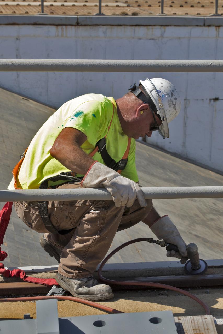
To continue his work, a construction worker secures clamps on a section of metal on the surface of Launch Pad 39B at NASA's Kennedy Space Center in Florida on July 26, 2018. The launch pad has undergone upgrades and modifications to accommodate NASA's Space Launch System and Orion spacecraft for Exploration Mission-1 and subsequent missions. Upgrades include new heat-resistant bricks on the walls of the flame trench and installation of a new flame deflector. All of the upgrades have been managed by Exploration Ground Systems.
A wet flow test at Launch Pad 39B on September 13, 2019, tests the sound suppression system that will be used for launch of NASA’s Space Launch System for the Artemis I mission. During the test, about 450,000 gallons of water poured onto the Pad B flame deflector, the mobile launcher flame hole and onto the launcher’s blast deck. This was the first time the ground launch sequencer that will be used on the day of launch was used for the timing of a sound suppression test.
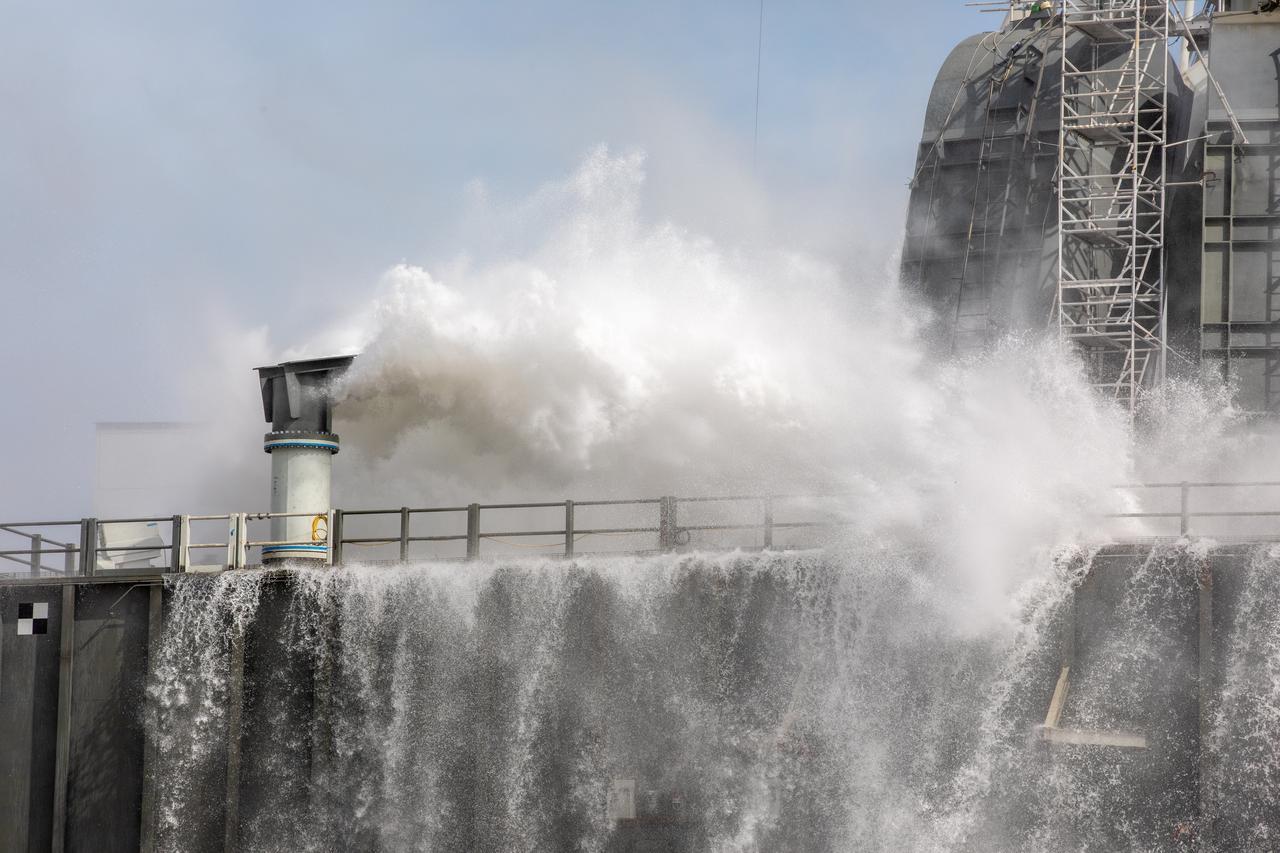
A wet flow test at Launch Pad 39B on September 13, 2019, tests the sound suppression system that will be used for launch of NASA’s Space Launch System for the Artemis I mission. During the test, about 450,000 gallons of water poured onto the Pad B flame deflector, the mobile launcher flame hole and onto the launcher’s blast deck. This was the first time the ground launch sequencer that will be used on the day of launch was used for the timing of a sound suppression test.
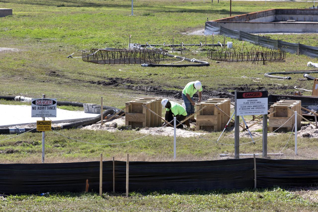
Construction workers stage parts and equipment nearby Launch Pad 39B at NASA’s Kennedy Space Center in Florida on Feb. 22, 2019. The launch pad has undergone upgrades and modifications to accommodate NASA's Space Launch System and Orion spacecraft for Exploration Mission-1 and subsequent missions. Upgrades include new heat-resistant bricks on the walls of the flame trench and installation of a new flame deflector. All of the upgrades have been managed by Exploration Ground Systems.
A construction worker sands a section of a wood beam on the surface of Launch Pad 39B at NASA’s Kennedy Space Center in Florida on Feb. 22, 2019. The launch pad has undergone upgrades and modifications to accommodate NASA's Space Launch System and Orion spacecraft for Exploration Mission-1 and subsequent missions. Upgrades include new heat-resistant bricks on the walls of the flame trench and installation of a new flame deflector. All of the upgrades have been managed by Exploration Ground Systems.
A wet flow test at Launch Pad 39B on September 13, 2019, tests the sound suppression system that will be used for launch of NASA’s Space Launch System for the Artemis I mission. During the test, about 450,000 gallons of water poured onto the Pad B flame deflector, the mobile launcher flame hole and onto the launcher’s blast deck. This was the first time the ground launch sequencer that will be used on the day of launch was used for the timing of a sound suppression test.
A wet flow test at Launch Pad 39B on September 13, 2019, tests the sound suppression system that will be used for launch of NASA’s Space Launch System for the Artemis I mission. During the test, about 450,000 gallons of water poured onto the Pad B flame deflector, the mobile launcher flame hole and onto the launcher’s blast deck. This was the first time the ground launch sequencer that will be used on the day of launch was used for the timing of a sound suppression test.

A wet flow test at Launch Pad 39B on September 13, 2019, tests the sound suppression system that will be used for launch of NASA’s Space Launch System for the Artemis I mission. During the test, about 450,000 gallons of water poured onto the Pad B flame deflector, the mobile launcher flame hole and onto the launcher’s blast deck. This was the first time the ground launch sequencer that will be used on the day of launch was used for the timing of a sound suppression test.
A wet flow test at Launch Pad 39B on September 13, 2019, tests the sound suppression system that will be used for launch of NASA’s Space Launch System for the Artemis I mission. During the test, about 450,000 gallons of water poured onto the Pad B flame deflector, the mobile launcher flame hole and onto the launcher’s blast deck. This was the first time the ground launch sequencer that will be used on the day of launch was used for the timing of a sound suppression test.
A wet flow test at Launch Pad 39B on September 13, 2019, tests the sound suppression system that will be used for launch of NASA’s Space Launch System for the Artemis I mission. During the test, about 450,000 gallons of water poured onto the Pad B flame deflector, the mobile launcher flame hole and onto the launcher’s blast deck. This was the first time the ground launch sequencer that will be used on the day of launch was used for the timing of a sound suppression test.
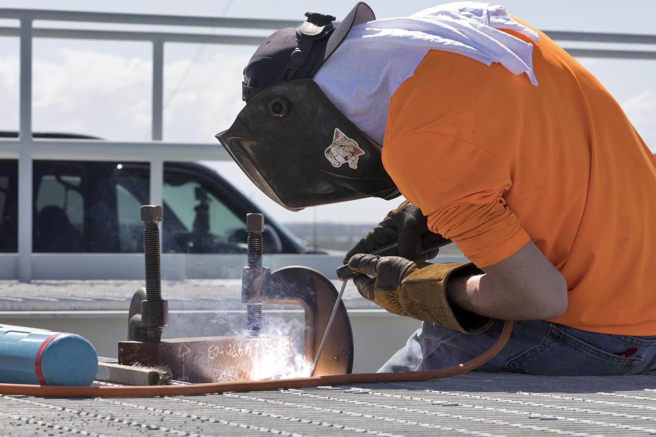
A construction worker welds a section of metal on the surface of Launch Pad 39B at NASA’s Kennedy Space Center in Florida on Feb. 22, 2019. The launch pad has undergone upgrades and modifications to accommodate NASA's Space Launch System and Orion spacecraft for Exploration Mission-1 and subsequent missions. Upgrades include new heat-resistant bricks on the walls of the flame trench and installation of a new flame deflector. All of the upgrades have been managed by Exploration Ground Systems.
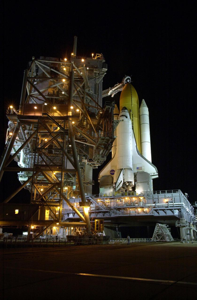
KENNEDY SPACE CENTER, FLA. -- In preparation for launch of Space Shuttle Atlantis on mission STS-110, the Rotating Service Structure (RSS) rolls back into launch position. The RSS provides protected access to the orbiter for changeout and servicing of payloads at the pad. The structure has access platforms at five levels to provide access to the payload bay. The Shuttle rests on the Mobile Launcher Platform (MLP), which straddles the flame trench below. The flame trench is part of the Flame Deflector System that insulates pad structures from the intense heat of a launch. Mission STS-110 is scheduled to launch April 4 on its 11-day mission to the International Space Station
CAPE CANAVERAL, Fla. – A view of the flame trench on Launch Pad 39A at NASA's Kennedy Space Center in Florida where repairs of the Fondue Fyre have been made. After launch of space shuttle Atlantis on the STS-125 mission on May 11, a 25-square-foot area of Fondue Fyre from the north side of the solid rocket booster flame deflector was damaged. Some pneumatic lines (gaseous nitrogen, pressurized air) in the area also were damaged and needed to be repaired. The flame trench channels the flames and smoke exhaust of the shuttle's solid rocket boosters away from the space shuttle during liftoff. Fondue Fyre is a fire-resistant concrete-like material that replaced the original flame trench bricks. It can be sprayed on the surface. Pad 39A will be used for the launch of space shuttle Endeavour on the STS-127 mission targeted for June 13. Photo credit: NASA/Jim Grossmann
CAPE CANAVERAL, Fla. – A view of the flame trench on Launch Pad 39A at NASA's Kennedy Space Center in Florida where repairs of the Fondue Fyre have been made. After launch of space shuttle Atlantis on the STS-125 mission on May 11, a 25-square-foot area of Fondue Fyre from the north side of the solid rocket booster flame deflector was damaged. Some pneumatic lines (gaseous nitrogen, pressurized air) in the area also were damaged and needed to be repaired. The flame trench channels the flames and smoke exhaust of the shuttle's solid rocket boosters away from the space shuttle during liftoff. Fondue Fyre is a fire-resistant concrete-like material that replaced the original flame trench bricks. It can be sprayed on the surface. Pad 39A will be used for the launch of space shuttle Endeavour on the STS-127 mission targeted for June 13. Photo credit: NASA/Jim Grossmann
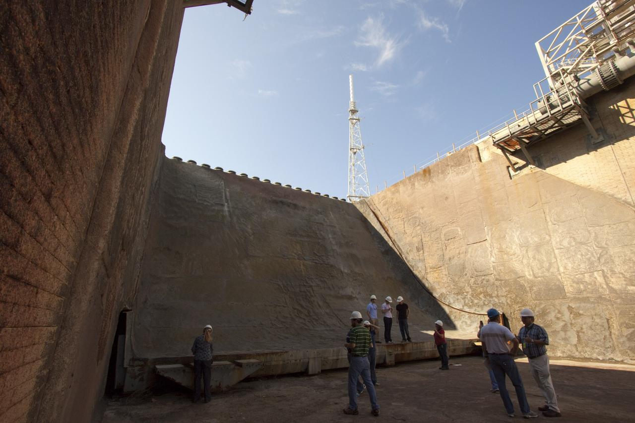
CAPE CANAVERAL, Fla. – Mechanical engineering students from Louisiana State University joined engineers and scientists at Launch Pad 39B at NASA's Kennedy Space Center in Florida as the students toured the facility to have a look at the flame trench. The students, standing on the flame deflector that divides the trench, signed up to help designers looking for new, flame and vibration-resistant materials to line the trench. The students are to build a scaled-down version of the flame trench that Kennedy's scientists can use to try out sample materials for the trench. If the samples work in the lab, they can be tried out in the real flame trenches at Launch Pad 39A and 39B. The launch pad has been refurbished extensively and work is continuing to modify the pad to support a variety of launch vehicles in the future. Photo credit: NASA/Jim Grossmann
CAPE CANAVERAL, Fla. – Mechanical engineering students from Louisiana State University joined engineers and scientists at Launch Pad 39B at NASA's Kennedy Space Center in Florida as the students toured the facility to have a look at the flame trench. The students, taking pictures of the flame deflector that divides the trench, signed up to help designers looking for new, flame and vibration-resistant materials to line the trench. The students are to build a scaled-down version of the flame trench that Kennedy's scientists can use to try out sample materials for the trench. If the samples work in the lab, they can be tried out in the real flame trenches at Launch Pad 39A and 39B. The launch pad has been refurbished extensively and work is continuing to modify the pad to support a variety of launch vehicles in the future. Photo credit: NASA/Jim Grossmann
CAPE CANAVERAL, Fla. – A view of the flame trench on Launch Pad 39A at NASA's Kennedy Space Center in Florida where repairs of the Fondue Fyre have been made. After launch of space shuttle Atlantis on the STS-125 mission on May 11, a 25-square-foot area of Fondue Fyre from the north side of the solid rocket booster flame deflector was damaged. Some pneumatic lines (gaseous nitrogen, pressurized air) in the area also were damaged and needed to be repaired. The flame trench channels the flames and smoke exhaust of the shuttle's solid rocket boosters away from the space shuttle during liftoff. Fondue Fyre is a fire-resistant concrete-like material that replaced the original flame trench bricks. It can be sprayed on the surface. Pad 39A will be used for the launch of space shuttle Endeavour on the STS-127 mission targeted for June 13. Photo credit: NASA/Jim Grossmann
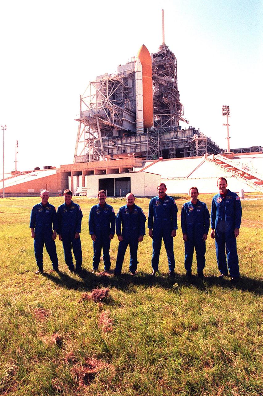
During Terminal Countdown Demonstration Test (TDCT) activities at Launch Pad 39B, the STS-103 crew pose in front of the flame trench, which is situated underneath the Mobile Launcher Platform holding Space Shuttle Discovery. Standing left to right are Mission Specialists Claude Nicollier of Switzerland, who is with the European Space Agency (ESA), C. Michael Foale (Ph.D.), John M. Grunsfeld (Ph.D.), Pilot Scott J. Kelly, Commander Curtis L. Brown Jr., and Mission Specialists Jean-François Clervoy of France, also with ESA, and Steven L. Smith. One of the solid rocket boosters and the external tank that are attached to Discovery can be seen in the photo. The flame trench is made of concrete and refractory brick, and contains an orbiter flame deflector on one side and solid rocket booster flame deflector on the other. The deflectors protect the flame trench floor and pad surface from the intense heat of launch. The TCDT provides the crew with emergency egress training, opportunities to inspect their mission payloads in the orbiter's payload bay, and simulated countdown exercises. STS-103 is a "call-up" mission due to the need to replace and repair portions of the Hubble Space Telescope, including the gyroscopes that allow the telescope to point at stars, galaxies and planets. The STS-103 crew will be replacing a Fine Guidance Sensor, an older computer with a new enhanced model, an older data tape recorder with a solid-state digital recorder, a failed spare transmitter with a new one, and degraded insulation on the telescope with new thermal insulation. The crew will also install a Battery Voltage/Temperature Improvement Kit to protect the spacecraft batteries from overcharging and overheating when the telescope goes into a safe mode. Four EVA's are planned to make the necessary repairs and replacements on the telescope. The mission is targeted for launch Dec. 6 at 2:37 a.m. EST