An artist’s concept of the transonic truss-braced wing aircraft configuration in flight over a forest of trees.
An artist’s concept of the transonic truss-braced wing aircraft configuration in flight over a forest of trees.
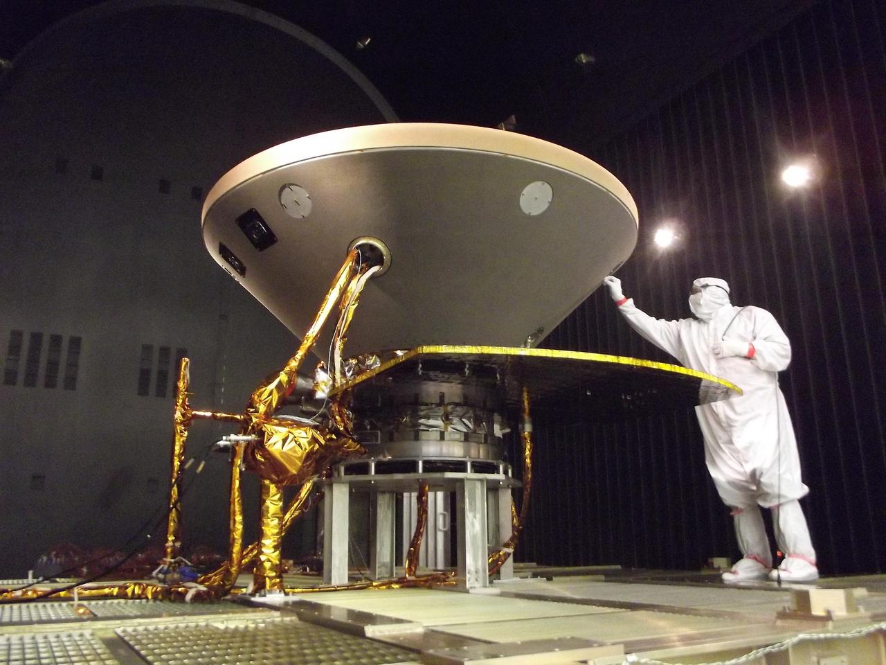
In this photo, a spacecraft specialist prepares NASA's InSight spacecraft for thermal vacuum testing in the flight system's "cruise" configuration for its 2016 flight to Mars. The testing simulates conditions of outer space that InSight will experience during its flight. The photo was taken on May 29, 2015, in a clean room of spacecraft assembly and test facilities at Lockheed Martin Space Systems, Denver. Note: After thorough examination, NASA managers have decided to suspend the planned March 2016 launch of the Interior Exploration using Seismic Investigations Geodesy and Heat Transport (InSight) mission. The decision follows unsuccessful attempts to repair a leak in a section of the prime instrument in the science payload. http://photojournal.jpl.nasa.gov/catalog/PIA19812
Crews at NASA’s Marshall Space Flight Center in Huntsville, Alabama, moved and installed the payload adapter that will be used in the Block 1B configuration of the SLS (Space Launch System) rocket from Building 4708, where it was manufactured, into Structural Test Stand 4697 at NASA’s Marshall Space Flight Center on March 13.
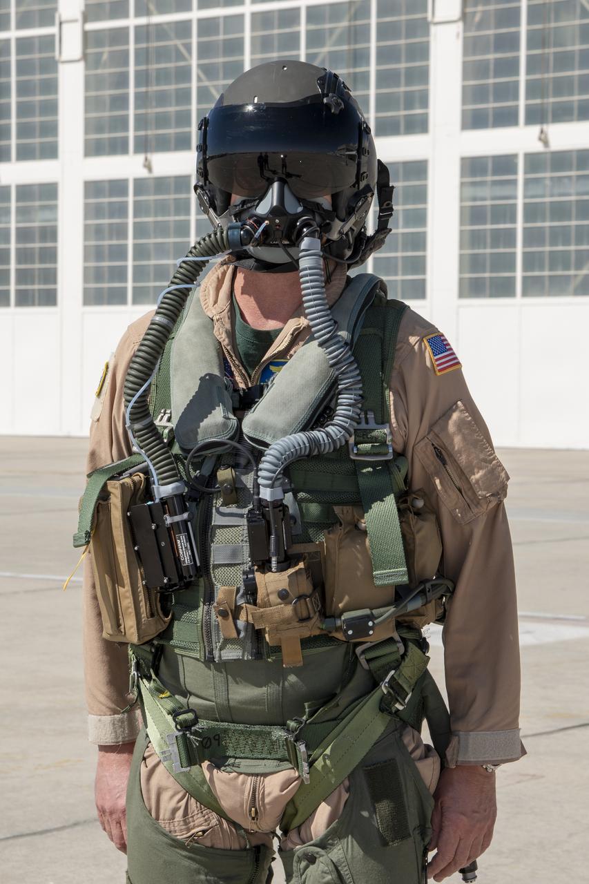
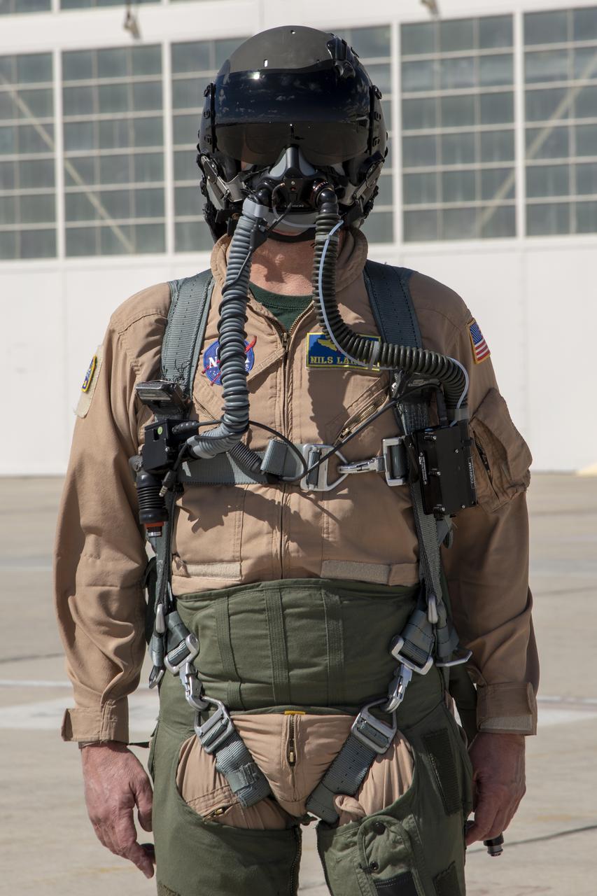
NASA Pilot Nils Larson wears a U.S. Navy harness configuration to show the integrated parachute harness and the built-in survival vest. The Navy configuration is bulkier and weighs more than the U.S. Air Force harness. Both configurations are being used in the Pilot Breathing Assessment program at NASA’s Armstrong Flight Research Center in California.
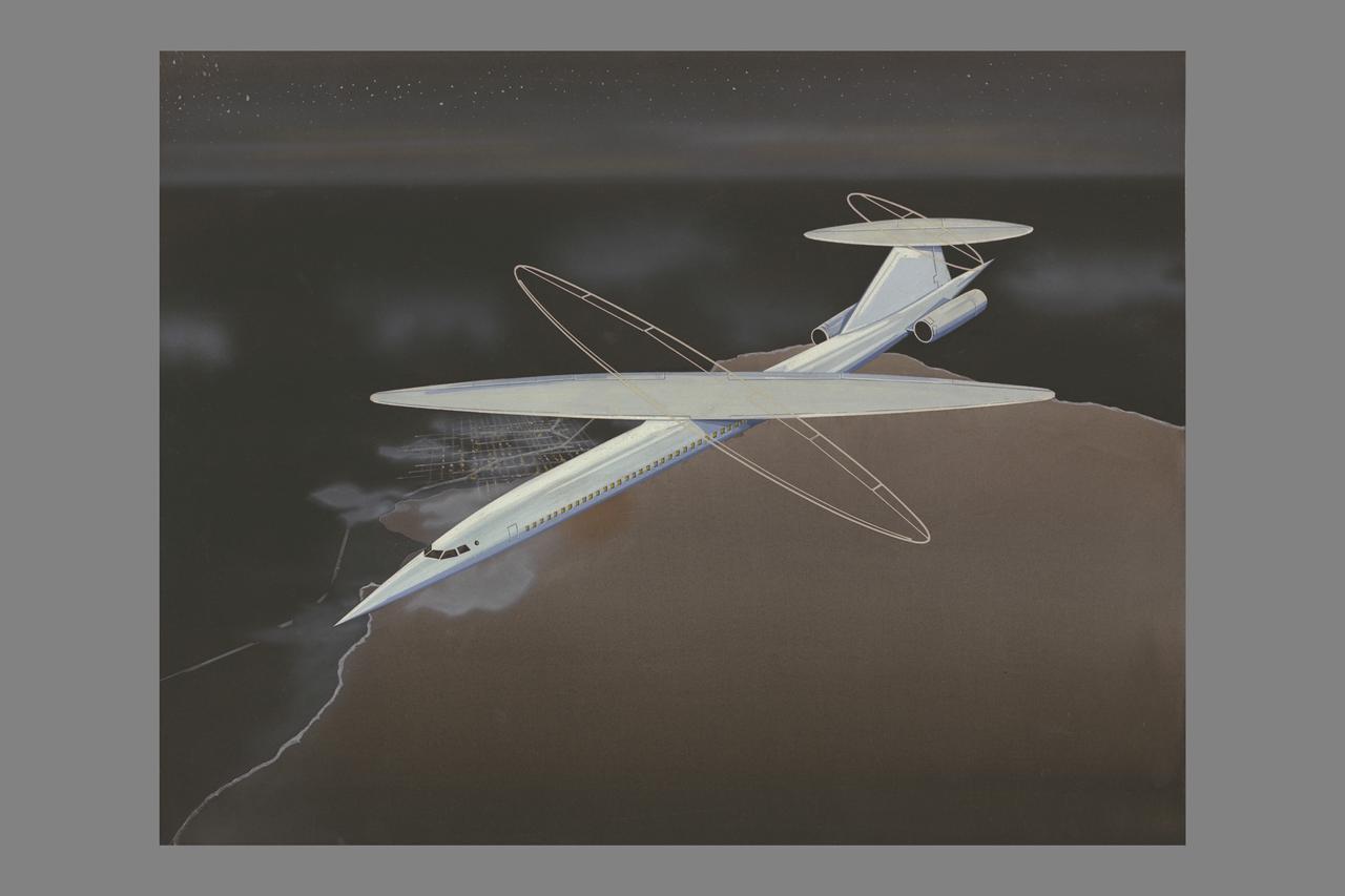
R.T. Jones Oblique Wing model: flight configuration
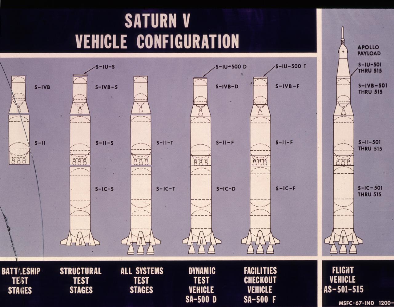
This illustration shows different configurations of the Saturn V test vehicles and flight vehicle.
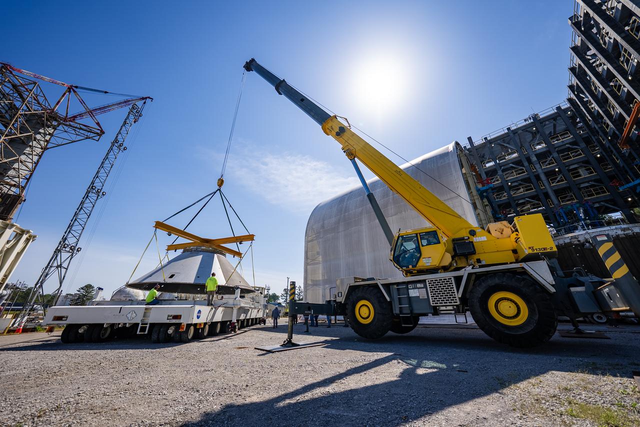
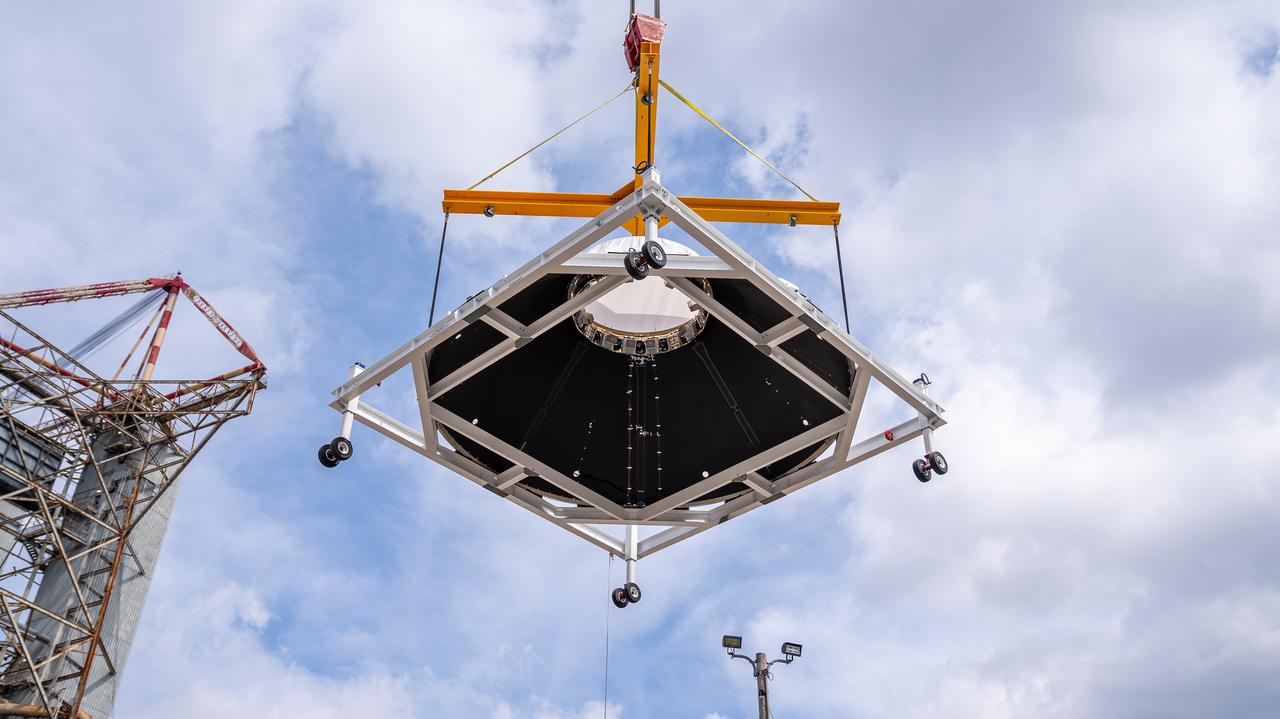
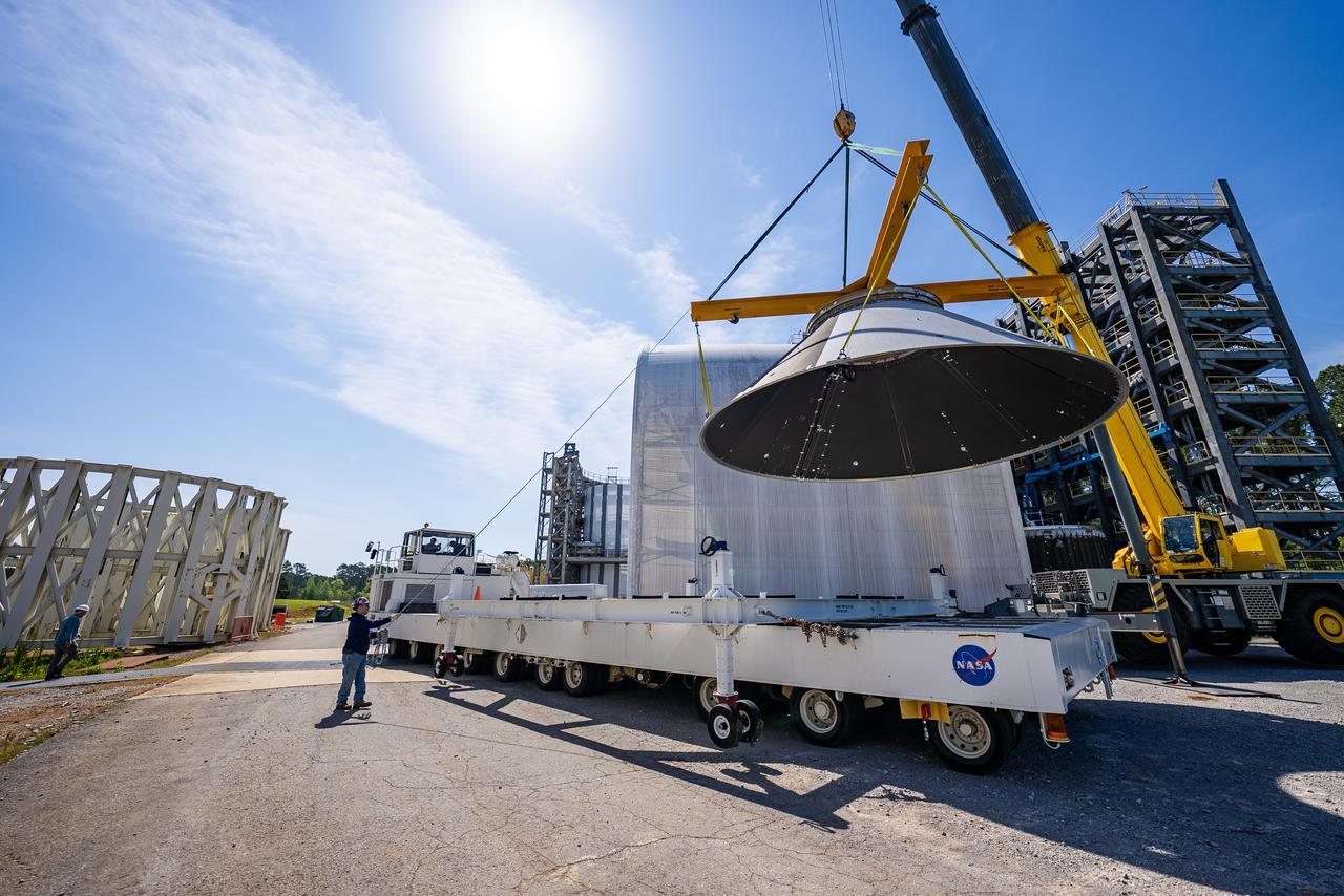
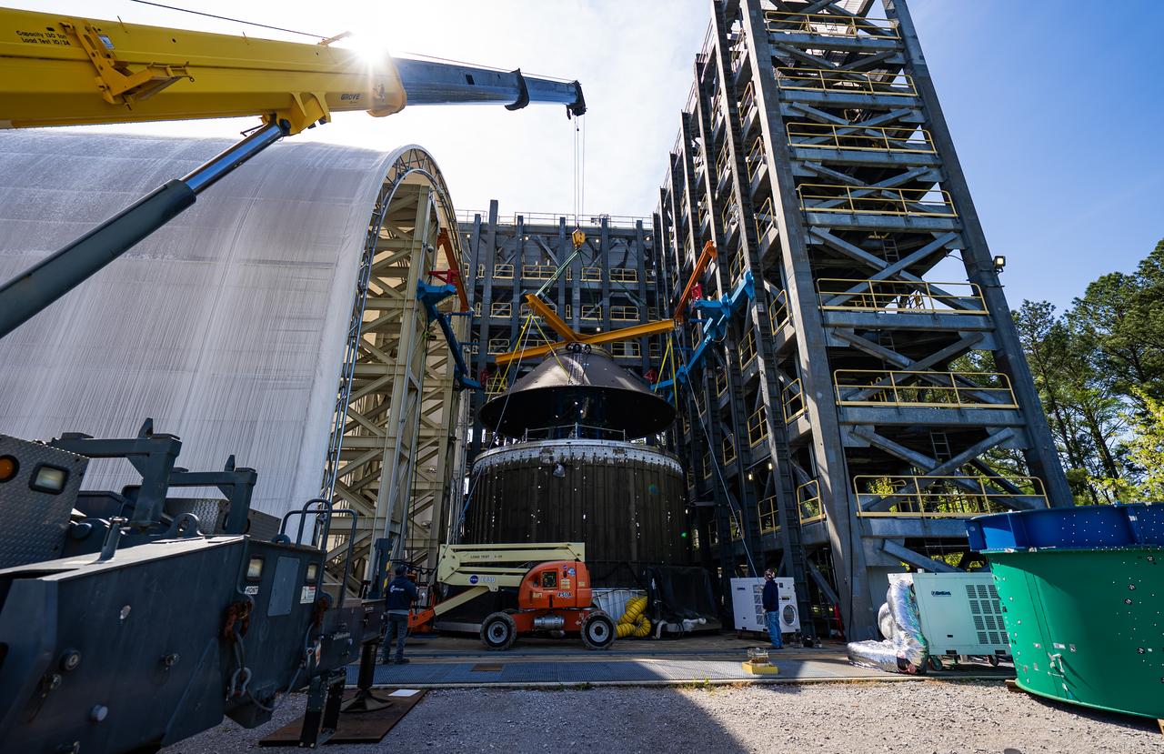
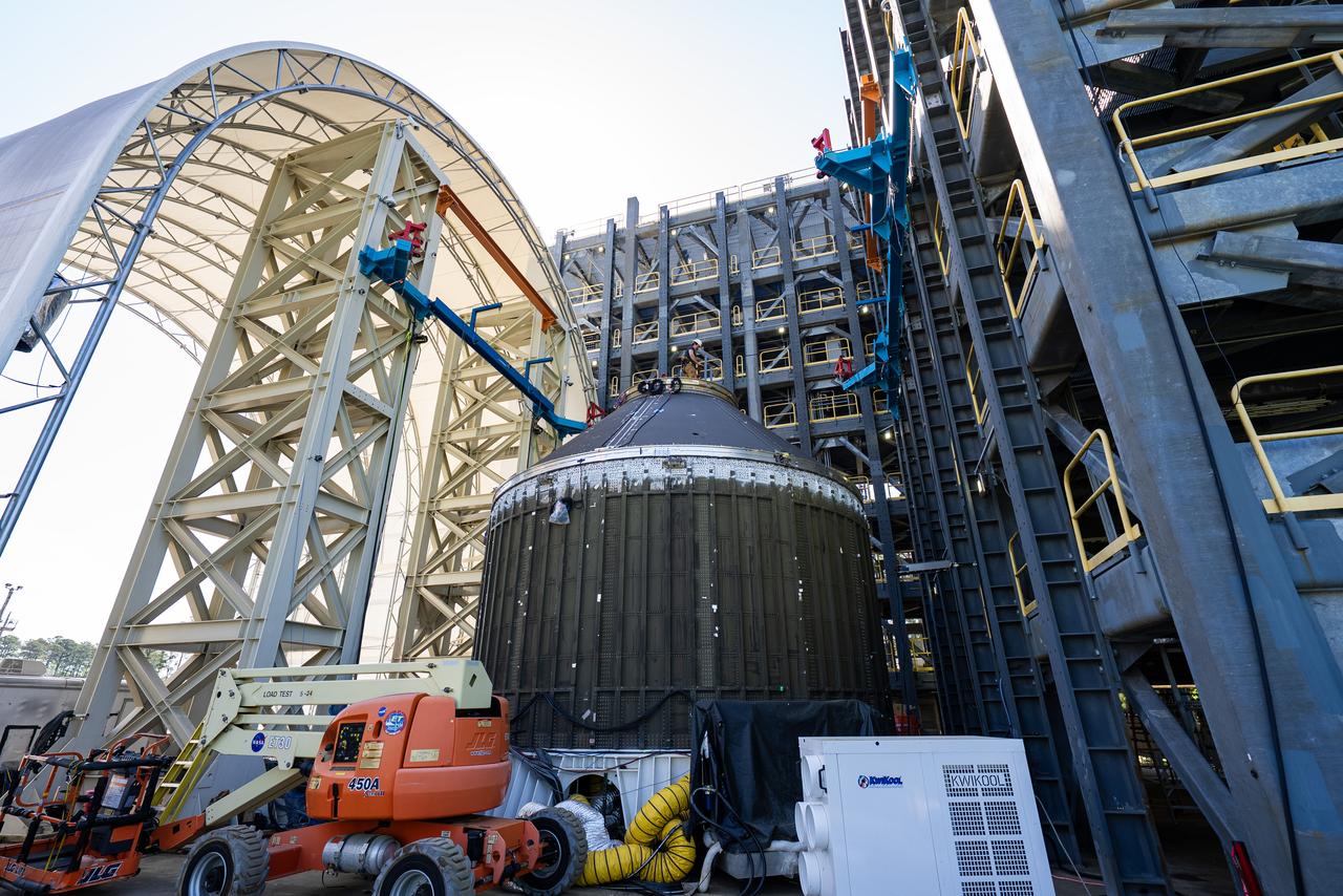
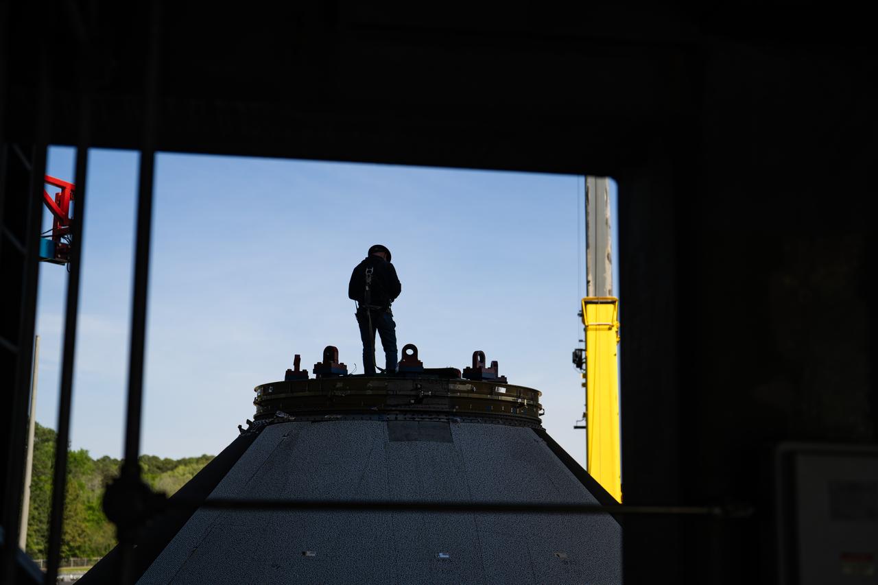
Technicians at NASA’s Marshall Space Flight Center in Huntsville, Alabama, are seen in these images taken April 17, 2025, moving the payload adapter test article from Building 4697 to Building 4705 for storage. This move marks the end of structural testing for the test article. Next, engineers will complete the qualification article and conduct additional for further testing before building the final flight hardware. Manufactured at Marshall, the test article underwent extensive and rigorous testing to validate the design before engineers finalized the configuration for the flight article. The newly completed composite payload adapter is an evolution from the Orion stage adapter to be used in the upgraded Block 1B configuration of the SLS (Space Launch System) rocket, debuting with Artemis IV.

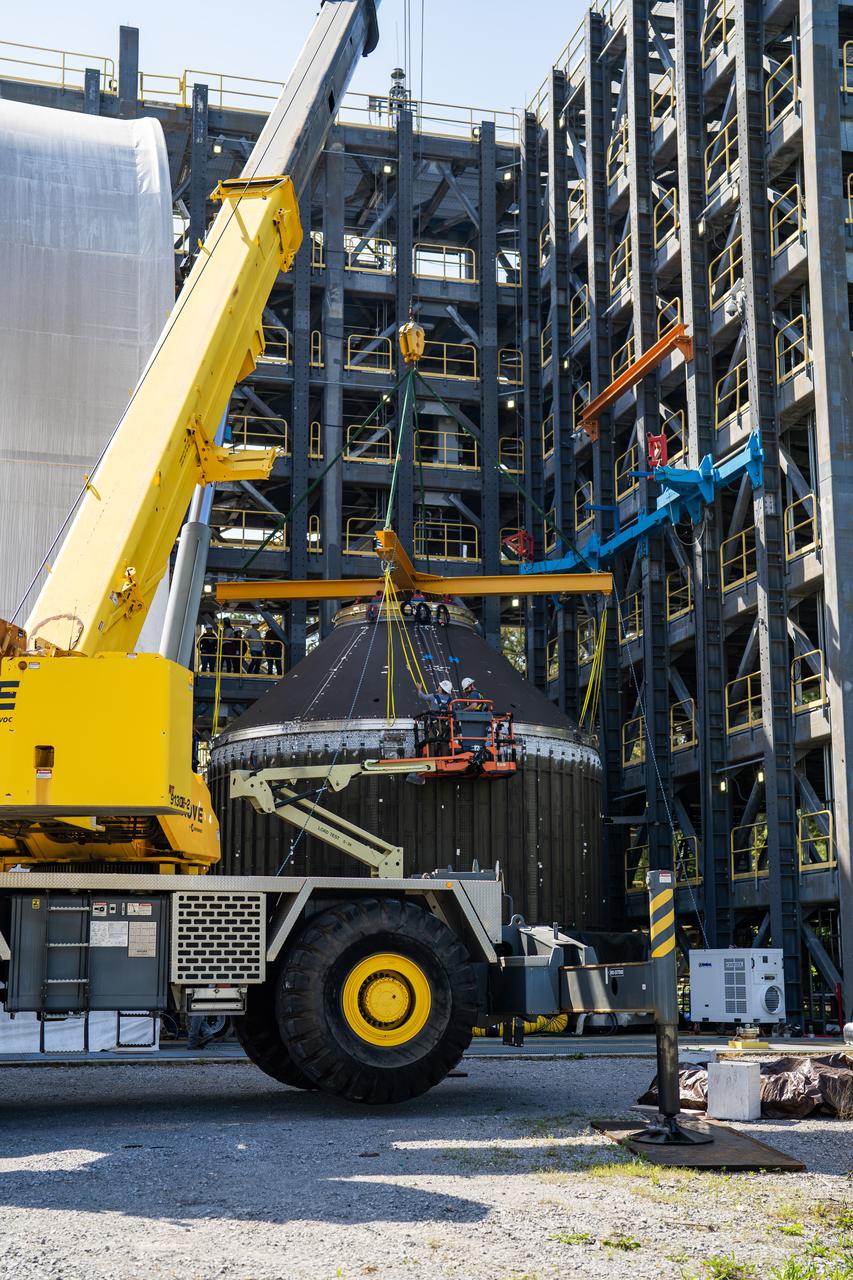
Technicians at NASA’s Marshall Space Flight Center in Huntsville, Alabama, are seen in these images taken April 17, 2025, moving the payload adapter test article from Building 4697 to Building 4705 for storage. This move marks the end of structural testing for the test article. Next, engineers will complete the qualification article and conduct additional for further testing before building the final flight hardware. Manufactured at Marshall, the test article underwent extensive and rigorous testing to validate the design before engineers finalized the configuration for the flight article. The newly completed composite payload adapter is an evolution from the Orion stage adapter to be used in the upgraded Block 1B configuration of the SLS (Space Launch System) rocket, debuting with Artemis IV.
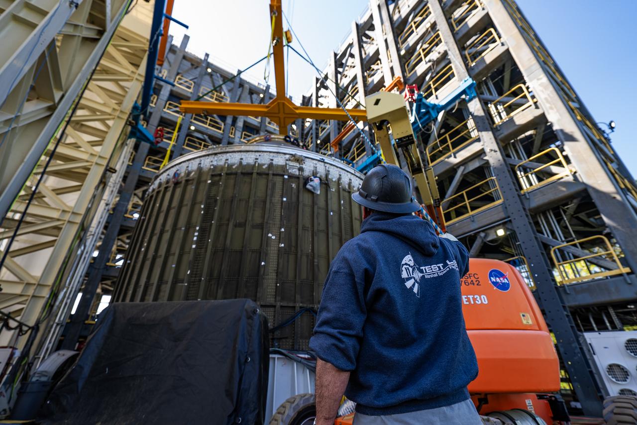
Technicians at NASA’s Marshall Space Flight Center in Huntsville, Alabama, are seen in these images taken April 17, 2025, moving the payload adapter test article from Building 4697 to Building 4705 for storage. This move marks the end of structural testing for the test article. Next, engineers will complete the qualification article and conduct additional for further testing before building the final flight hardware. Manufactured at Marshall, the test article underwent extensive and rigorous testing to validate the design before engineers finalized the configuration for the flight article. The newly completed composite payload adapter is an evolution from the Orion stage adapter to be used in the upgraded Block 1B configuration of the SLS (Space Launch System) rocket, debuting with Artemis IV.
Technicians at NASA’s Marshall Space Flight Center in Huntsville, Alabama, are seen in these images taken April 17, 2025, moving the payload adapter test article from Building 4697 to Building 4705 for storage. This move marks the end of structural testing for the test article. Next, engineers will complete the qualification article and conduct additional for further testing before building the final flight hardware. Manufactured at Marshall, the test article underwent extensive and rigorous testing to validate the design before engineers finalized the configuration for the flight article. The newly completed composite payload adapter is an evolution from the Orion stage adapter to be used in the upgraded Block 1B configuration of the SLS (Space Launch System) rocket, debuting with Artemis IV.
Technicians at NASA’s Marshall Space Flight Center in Huntsville, Alabama, are seen in these images taken April 17, 2025, moving the payload adapter test article from Building 4697 to Building 4705 for storage. This move marks the end of structural testing for the test article. Next, engineers will complete the qualification article and conduct additional for further testing before building the final flight hardware. Manufactured at Marshall, the test article underwent extensive and rigorous testing to validate the design before engineers finalized the configuration for the flight article. The newly completed composite payload adapter is an evolution from the Orion stage adapter to be used in the upgraded Block 1B configuration of the SLS (Space Launch System) rocket, debuting with Artemis IV.
Technicians at NASA’s Marshall Space Flight Center in Huntsville, Alabama, are seen in these images taken April 17, 2025, moving the payload adapter test article from Building 4697 to Building 4705 for storage. This move marks the end of structural testing for the test article. Next, engineers will complete the qualification article and conduct additional for further testing before building the final flight hardware. Manufactured at Marshall, the test article underwent extensive and rigorous testing to validate the design before engineers finalized the configuration for the flight article. The newly completed composite payload adapter is an evolution from the Orion stage adapter to be used in the upgraded Block 1B configuration of the SLS (Space Launch System) rocket, debuting with Artemis IV.
Technicians at NASA’s Marshall Space Flight Center in Huntsville, Alabama, are seen in these images taken April 17, 2025, moving the payload adapter test article from Building 4697 to Building 4705 for storage. This move marks the end of structural testing for the test article. Next, engineers will complete the qualification article and conduct additional for further testing before building the final flight hardware. Manufactured at Marshall, the test article underwent extensive and rigorous testing to validate the design before engineers finalized the configuration for the flight article. The newly completed composite payload adapter is an evolution from the Orion stage adapter to be used in the upgraded Block 1B configuration of the SLS (Space Launch System) rocket, debuting with Artemis IV.
Technicians at NASA’s Marshall Space Flight Center in Huntsville, Alabama, are seen in these images taken April 17, 2025, moving the payload adapter test article from Building 4697 to Building 4705 for storage. This move marks the end of structural testing for the test article. Next, engineers will complete the qualification article and conduct additional for further testing before building the final flight hardware. Manufactured at Marshall, the test article underwent extensive and rigorous testing to validate the design before engineers finalized the configuration for the flight article. The newly completed composite payload adapter is an evolution from the Orion stage adapter to be used in the upgraded Block 1B configuration of the SLS (Space Launch System) rocket, debuting with Artemis IV.
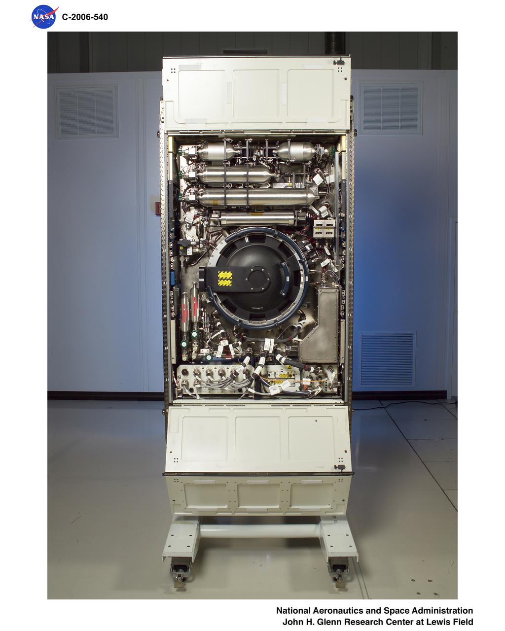
Combustion Integrated Rack (CIR)
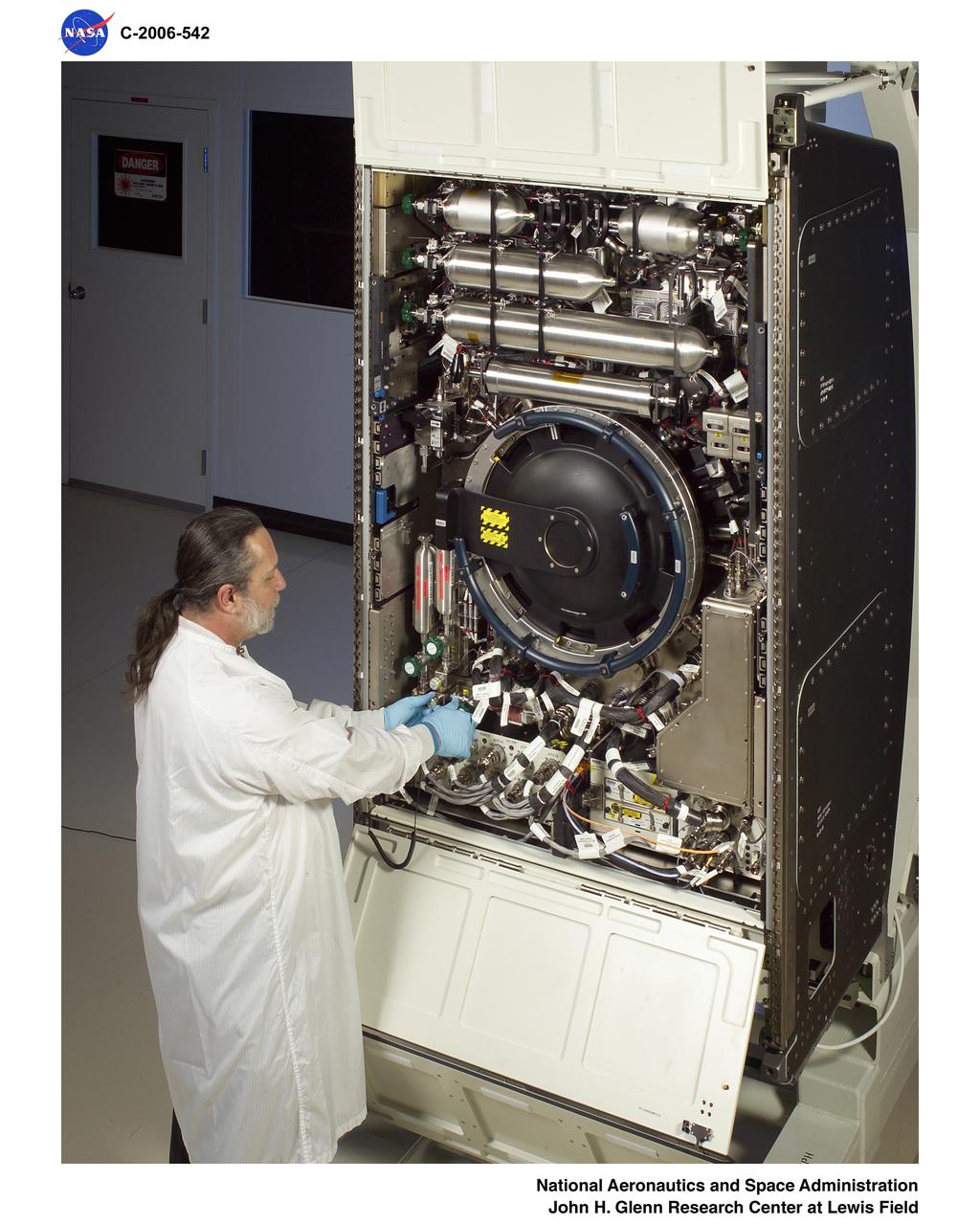
Combustion Integrated Rack (CIR)
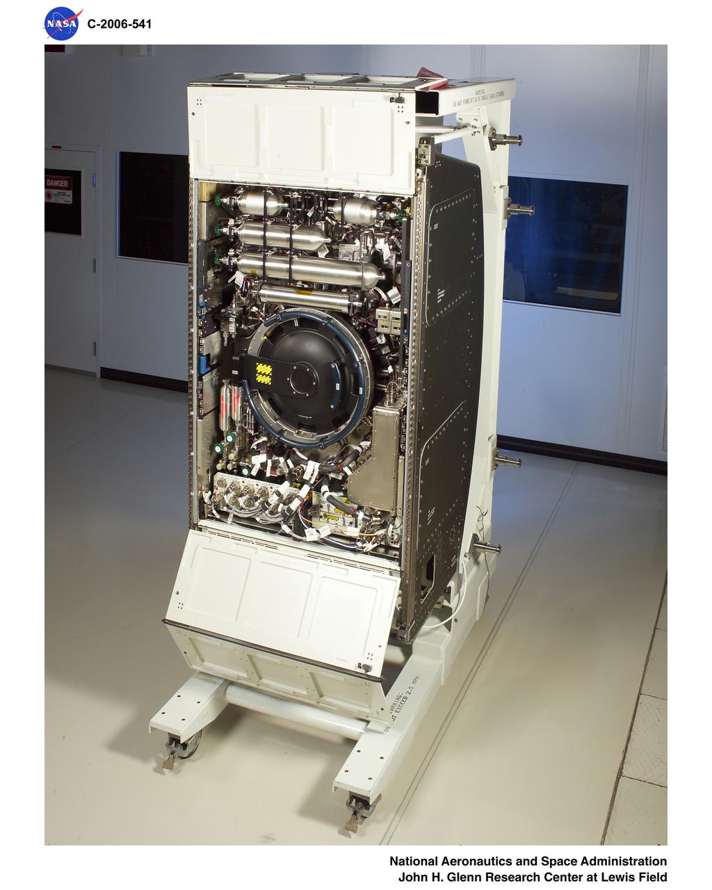
Combustion Integrated Rack (CIR)
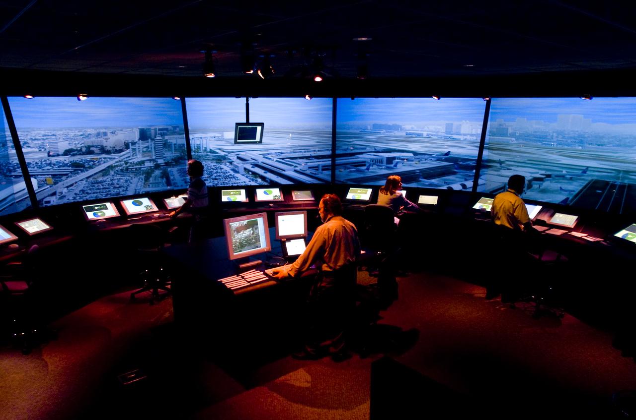
FFC (Future Flight Central) Simulator interior 'LAX' Configuration with Ken Christensen in tower
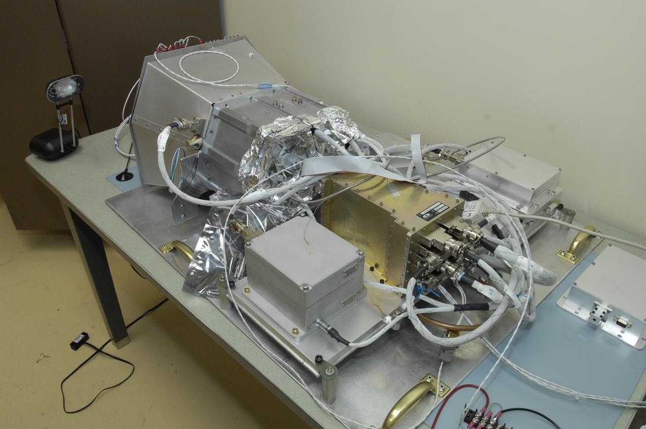
LCROSS in Clean Room at Ames Research Centeer - flight hardware in Thermal Cycle configuration with _______
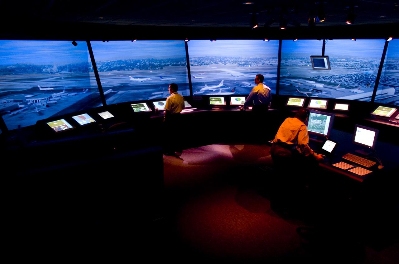
FFC (Future Flight Central) Simulator interior 'LAX' Configuration with Ken Christensen in tower
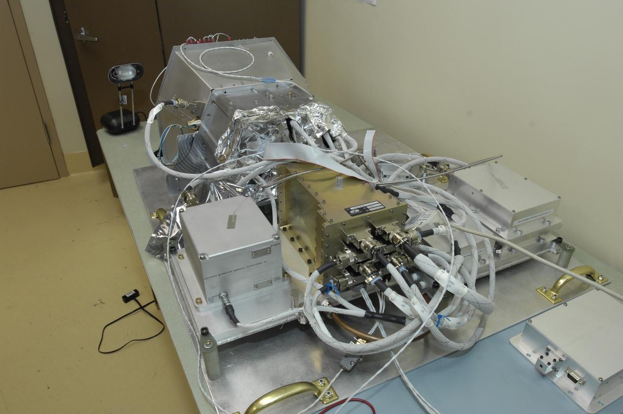
LCROSS in Clean Room at Ames Research Centeer - flight hardware in Thermal Cycle configuration with _______
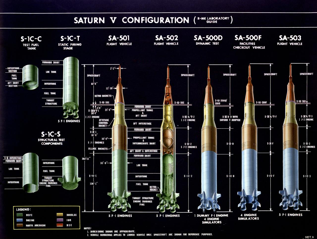
This chart illustrates the testing vehicle and flight vehicle configurations, in addition to the approximate dimensions of the stages of the Saturn V launch vehicle.

FFC (Future Flight Central) Simulator interior 'LAX' Configuration with Ken Christensen in pilots room

FFC (Future Flight Central) Simulator interior 'LAX' Configuration with Ken Christensen in pilots room

FFC (Future Flight Central) Simulator interior 'LAX' Configuration with Ken Christensen in tower

FFC (Future Flight Central) Simulator interior 'LAX' Configuration with Ken Christensen in tower
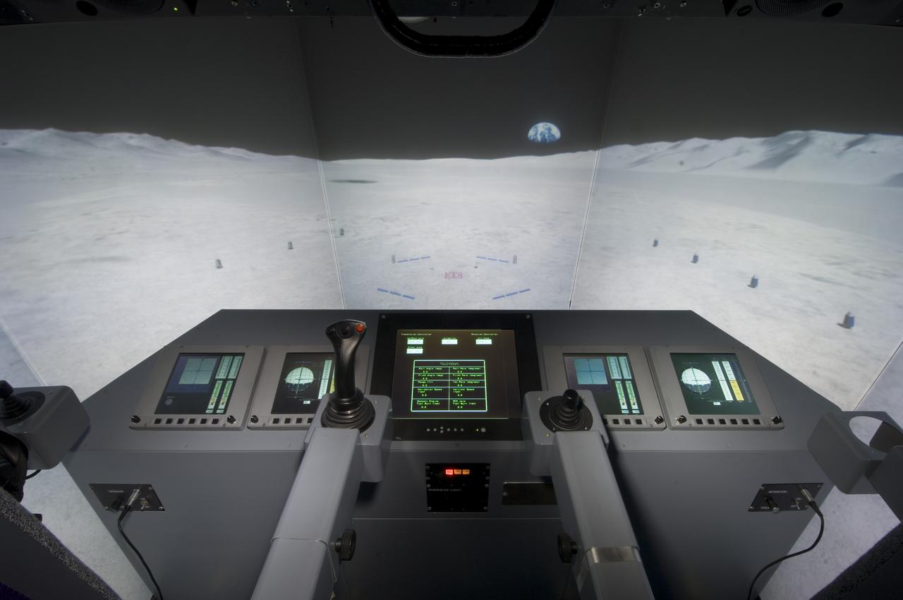
LUNAR SURFACE ACCESS MODULE (LSAM) CONFIGURATION VMS N-CAB INSTRUMENT PANEL, SEATS, FLIGHT CONTROLS, RESTRAINING SYSTEM OTW
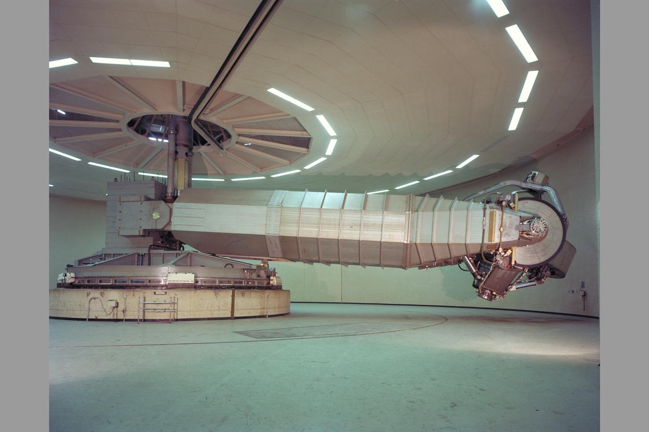
N-243 Flight and Guidance Centrifuge: Is used for spacecraft mission simulations and is adaptable to two configurations. Configuration 1: The cab will accommodate a three-man crew for space mission research. The accelerations and rates are intended to be smoothly applicable at very low value so the navigation and guidance procedures using a high-accuracy, out-the window display may be simulated. Configuration 2: The simulator can use a one-man cab for human tolerance studies and performance testing. Atmosphere and tempertaure can be varied as stress inducements. This simlator is operated closed-loop with digital or analog computation. It is currently man-rated for 3.5g maximum.
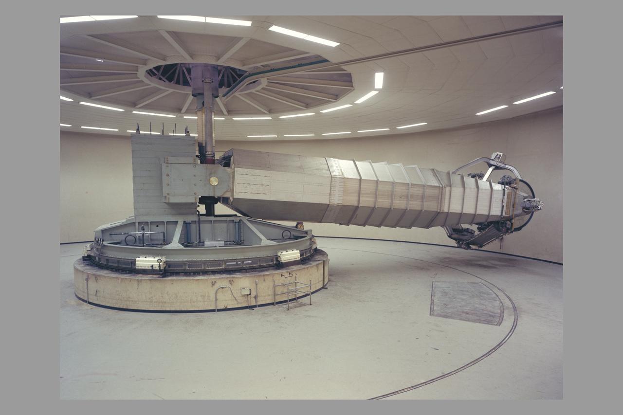
N-243 Flight and Guidance Centrifuge: Is used for spacecraft mission simulations and is adaptable to two configurations. Configuration 1: The cab will accommodate a three-man crew for space mission research. The accelerations and rates are intended to be smoothly applicable at very low value so the navigation and guidance procedures using a high-accuracy, out-the window display may be simulated. Configuration 2: The simulator can use a one-man cab for human tolerance studies and performance testing. Atmosphere and tempertaure can be varied as stress inducements. This simlator is operated closed-loop with digital or analog computation. It is currently man-rated for 3.5g maximum.
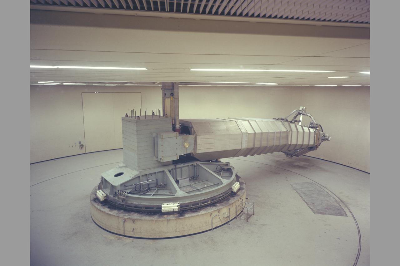
N-243 Flight and Guidance Centrifuge: Is used for spacecraft mission simulations and is adaptable to two configurations. Configuration 1: The cab will accommodate a three-man crew for space mission research. The accelerations and rates are intended to be smoothly applicable at very low value so the navigation and guidance procedures using a high-accuracy, out-the window display may be simulated. Configuration 2: The simulator can use a one-man cab for human tolerance studies and performance testing. Atmosphere and tempertaure can be varied as stress inducements. This simlator is operated closed-loop with digital or analog computation. It is currently man-rated for 3.5g maximum.
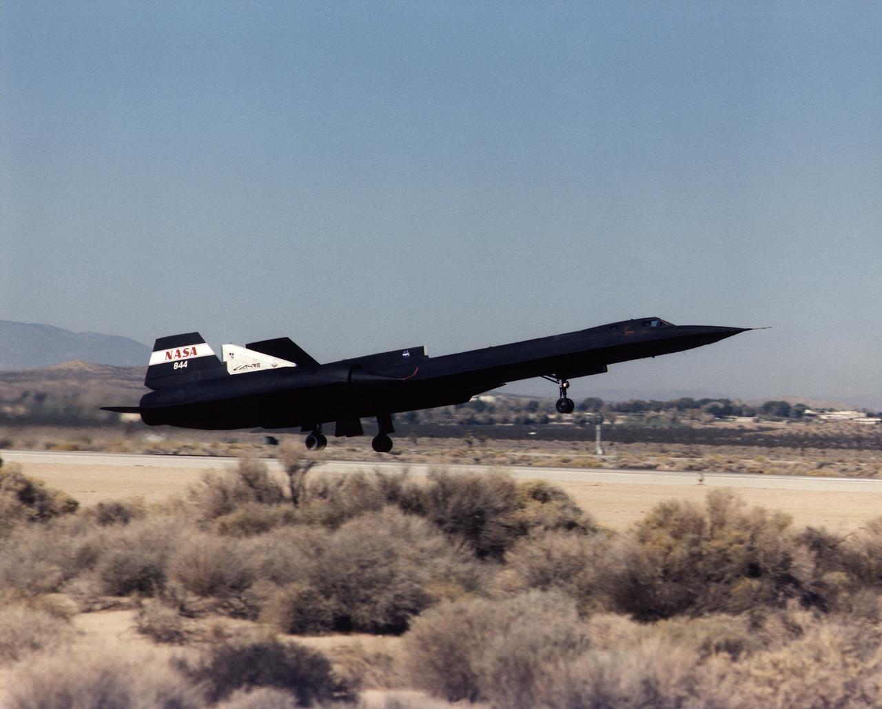
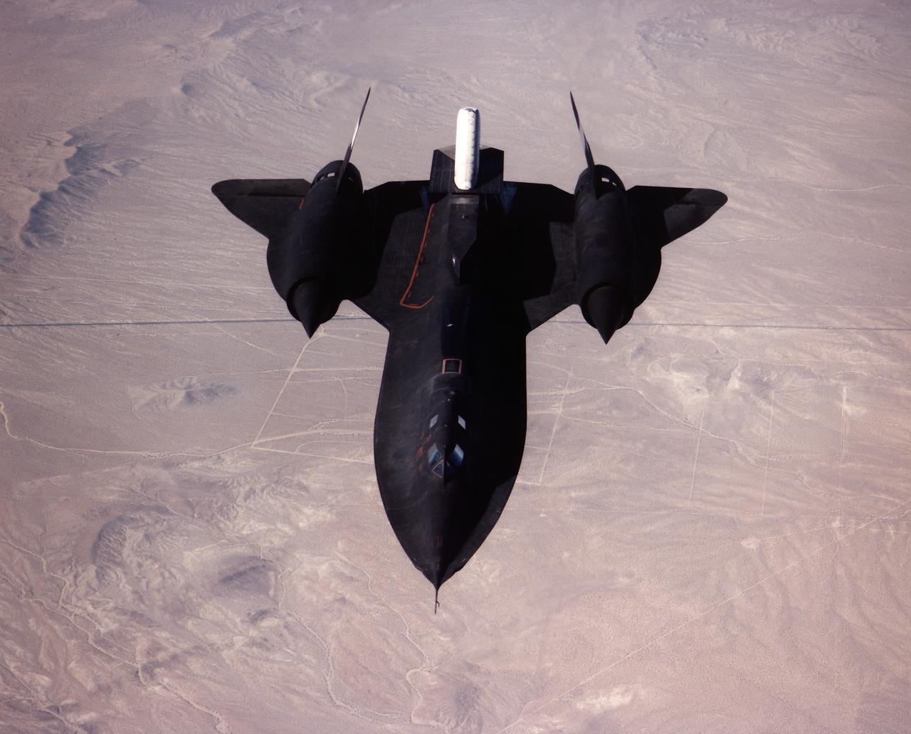
A NASA SR-71 takes off Oct. 31, making its first flight as part of the NASA/Rocketdyne/Lockheed Martin Linear Aerospike SR-71 Experiment (LASRE) at NASA's Dryden Flight Research Center, Edwards, California. The SR-71 took off at 8:31 a.m. PST. The aircraft flew for one hour and fifty minutes, reaching a maximum speed of Mach 1.2 before landing at Edwards at 10:21 a.m. PST, successfully validating the SR-71/linear aerospike experiment configuration. The goal of the first flight was to evaluate the aerodynamic characteristics and the handling of the SR-71/linear aerospike experiment configuration. The engine was not fired during the flight.
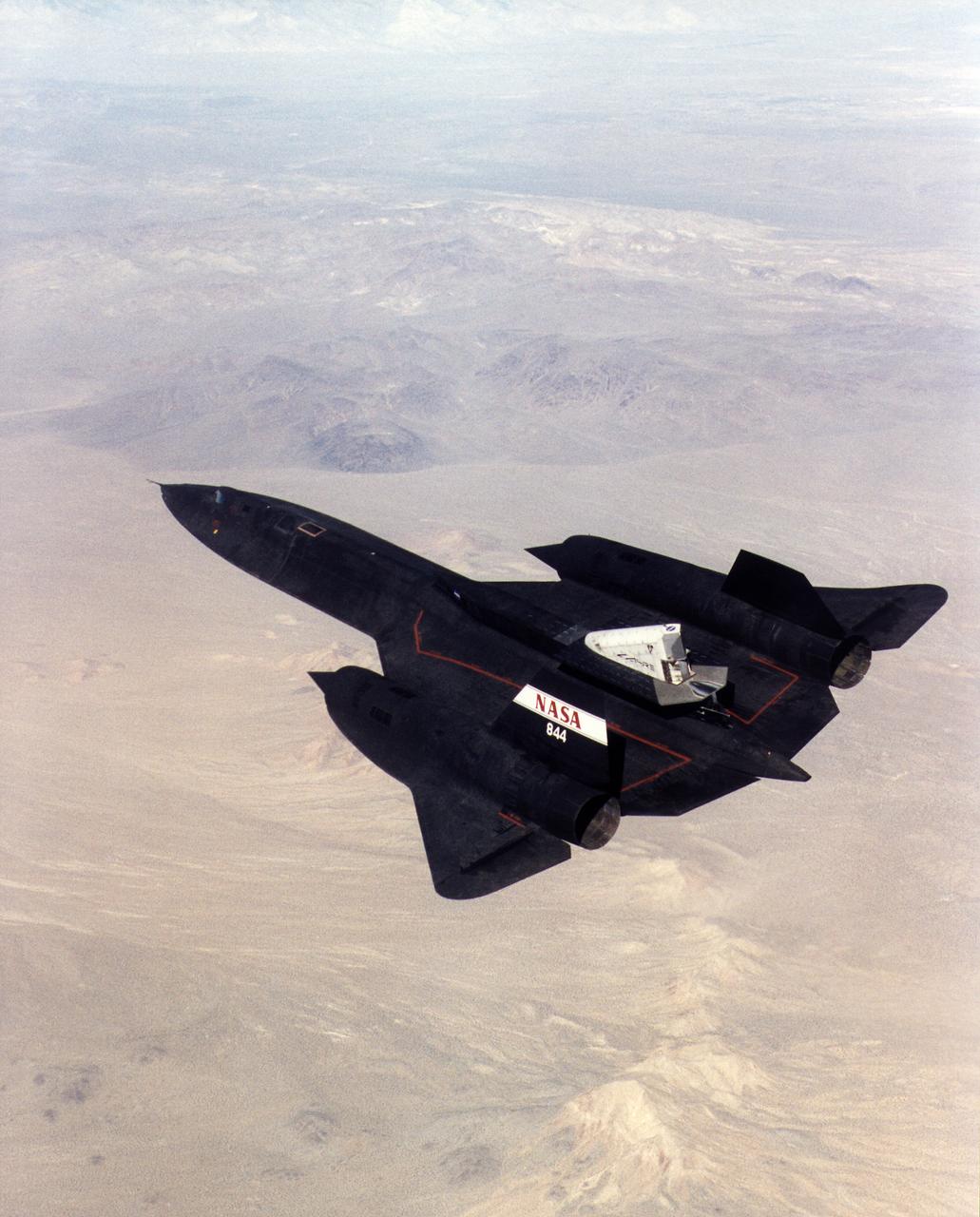
A NASA SR-71 successfully completed its first flight 31 October 1997 as part of the NASA/Rocketdyne/Lockheed Martin Linear Aerospike SR-71 Experiment (LASRE) at NASA's Dryden Flight Research Center, Edwards, California. The SR-71 took off at 8:31 a.m. PST. The aircraft flew for one hour and fifty minutes, reaching a maximum speed of Mach 1.2 before landing at Edwards at 10:21 a.m. PST, successfully validating the SR-71/linear aerospike experiment configuration. The goal of the first flight was to evaluate the aerodynamic characteristics and the handling of the SR-71/linear aerospike experiment configuration. The engine was not fired during the flight.
A NASA SR-71 made its successful first flight Oct. 31 as part of the NASA/Rocketdyne/ Lockheed Martin Linear Aerospike SR-71 Experiment (LASRE) at NASA's Dryden Flight Research Center, Edwards, California. The SR-71 took off at 8:31 a.m. PST. The aircraft flew for one hour and fifty minutes, reaching a maximum speed of Mach 1.2 before landing at Edwards at 10:21 a.m. PST, successfully validating the SR-71/linear aerospike experiment configuration. The goal of the first flight was to evaluate the aerodynamic characteristics and the handling of the SR-71/linear aerospike experiment configuration. The engine was not fired during the flight.
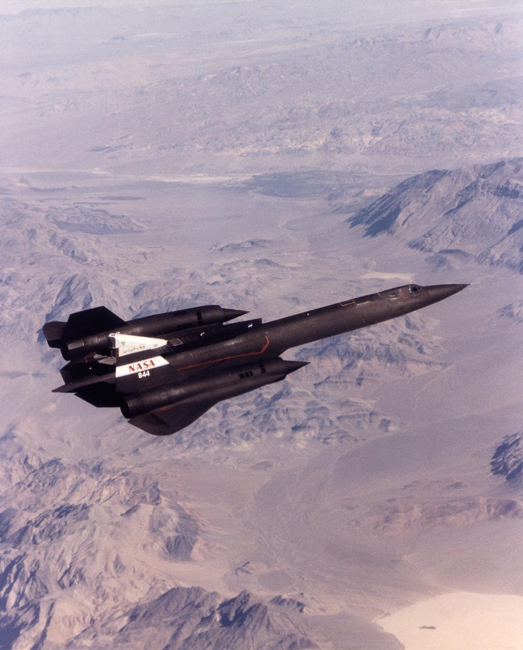
A NASA SR-71 successfully completed its first flight 31 October 1997 as part of the NASA/Rocketdyne/Lockheed Martin Linear Aerospike SR-71 Experiment (LASRE) at NASA's Dryden Flight Research Center, Edwards, California. The SR-71 took off at 8:31 a.m. PST. The aircraft flew for one hour and fifty minutes, reaching a maximum speed of Mach 1.2 before landing at Edwards at 10:21 a.m. PST, successfully validating the SR-71/linear aerospike experiment configuration. The goal of the first flight was to evaluate the aerodynamic characteristics and the handling of the SR-71/linear aerospike experiment configuration. The engine was not fired during the flight.
A NASA SR-71 made its successful first flight Oct. 31 as part of the NASA/Rocketdyne/Lockheed Martin Linear Aerospike SR-71 Experiment (LASRE) at NASA's Dryden Flight Research Center, Edwards, California. The SR-71 took off at 8:31 a.m. PST. The aircraft flew for one hour and fifty minutes, reaching a maximum speed of Mach 1.2 before landing at Edwards at 10:21 a.m. PST, successfully validating the SR-71/linear aerospike experiment configuration. The goal of the first flight was to evaluate the aerodynamic characteristics and the handling of the SR-71/linear aerospike experiment configuration. The engine was not fired during the flight.
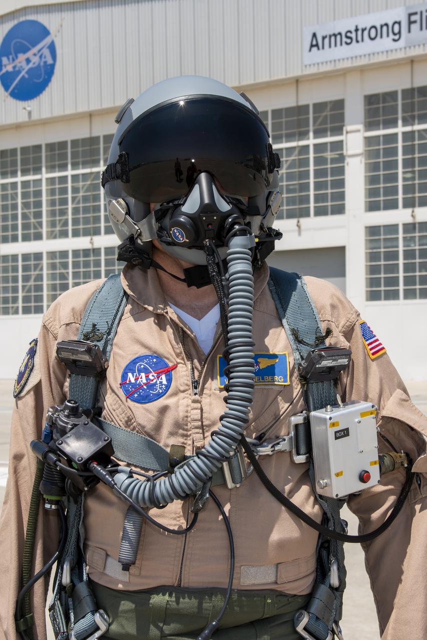
NASA research pilot Wayne Ringelberg wears a U.S. Air Force configuration of the NASA Jet Propulsion Laboratory in California prototype mask, which uses laser sensors to determine levels of carbon dioxide and water exhaled inside the mask. This prototype was tested in conjunction with the current VigilOX system, which measures the pilot’s oxygen concentration, breathing pressures and flow rates. This and the U.S. Navy configuration was used in the Pilot Breathing Assessment program at NASA’s Armstrong Flight Research Center in California.
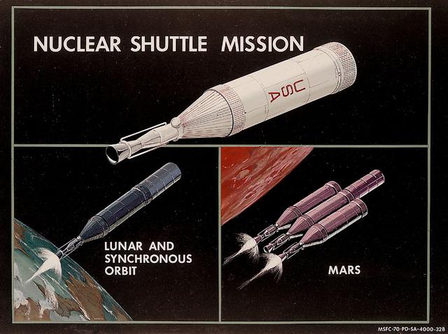
In this 1970 artist's concept, the Nuclear Shuttle is shown in its lunar and geosynchronous orbit configuration and in its planetary mission configuration. As envisioned by Marshall Space Flight Center Program Development plarners, the Nuclear Shuttle would deliver payloads to lunar orbit or other destinations then return to Earth orbit for refueling. A cluster of Nuclear Shuttle units could form the basis for planetary missions.
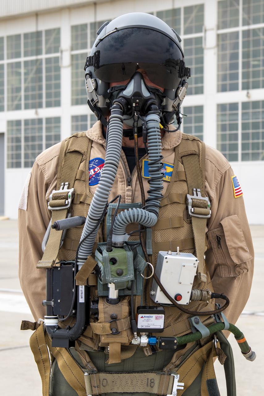
NASA research pilot Jim Less wears a U.S. Navy harness configuration with the NASA Jet Propulsion Laboratory in California prototype mask, which uses laser sensors to determine levels of carbon dioxide and water exhaled inside the mask. This prototype was tested in conjunction with the current VigilOX system, which measures the pilot’s oxygen concentration, breathing pressures and flow rates. This and the U.S. Air Force configuration was used in the Pilot Breathing Assessment program at NASA’s Armstrong Flight Research Center in California.

iss060e029526 (Aug. 8, 2019) --- Expedition 60 Flight Engineer Christina Koch of NASA works inside the U.S. Quest airlock configuring a pair spacesuits that NASA astronauts Nick Hague and Andrew Morgan will wear during a spacewalk on Aug. 21. The duo will spend about six and a half hours routing cables and configuring the International Docking Adapter-3 on top of the Harmony module in preparation for the arrival of future SpaceX and Boeing crew vehicles.
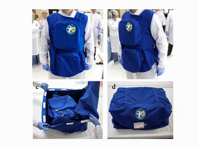
jsc2021e009421 (3/2/2021) --- A preflight view of the PERSEO garment prototype inspection and configuration for launch. (a,b) Garment worn during pre-flight inspections at Johnson Space Center (JSC) in Houston, USA, before launch, front and lateral view. (c) Garment folded in the transport bag for the launch configuration. (d) Closed transport bag containing.the garment. Image courtesy of the Italian Space Agency (ASI).
iss071e522256 (Aug. 21, 2024) --- NASA astronaut and Expedition 71 Flight Engineer Matthew Dominick checks CubeSat configurations packed inside launch cases installed in the Kibo laboratory module's Small Satellite Orbital Deployer.
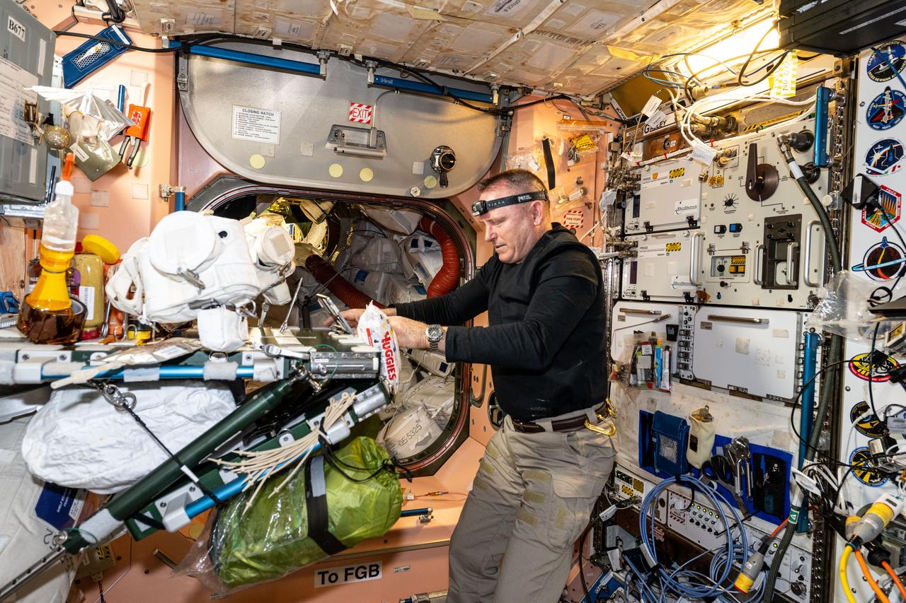
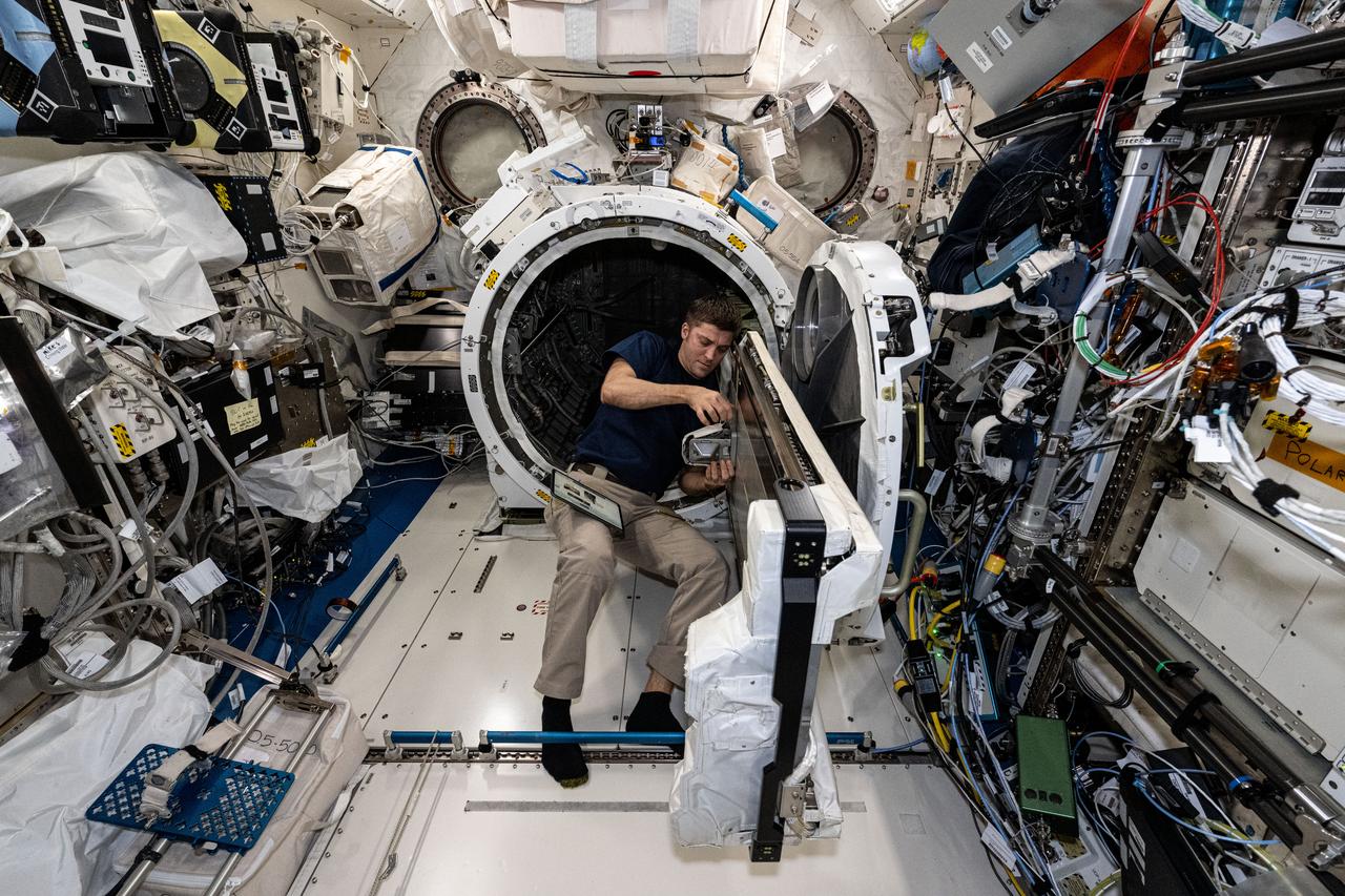
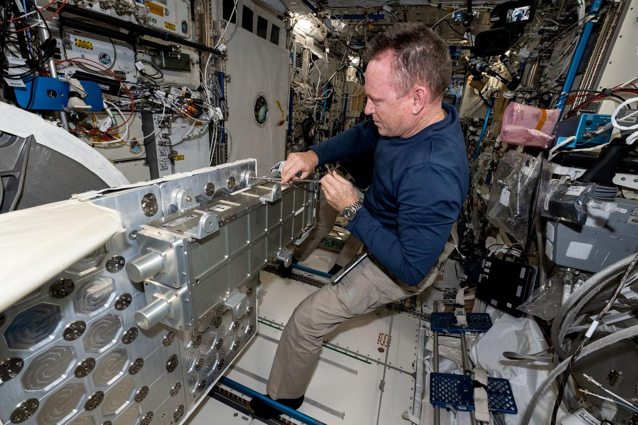
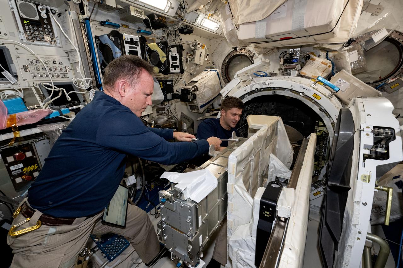
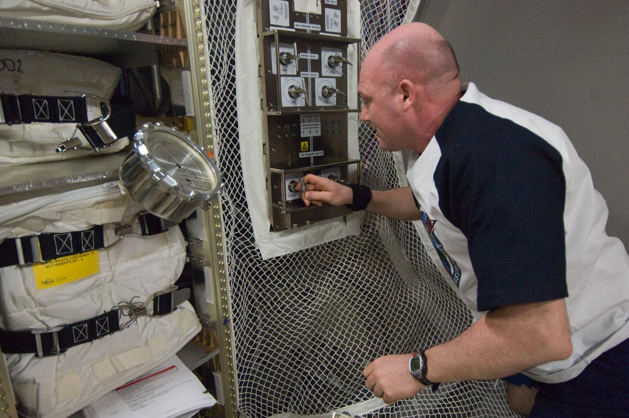
iss072e472714 (Jan. 14, 2025) --- NASA astronaut and Expedition 72 Flight Engineer Butch Wilmore configures spacewalking hardware aboard the International Space Station's Unity module.
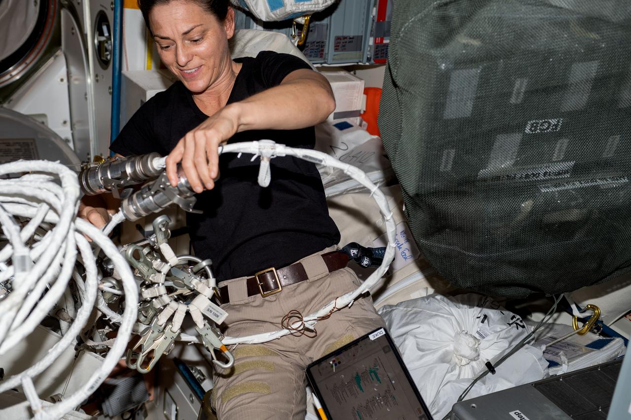
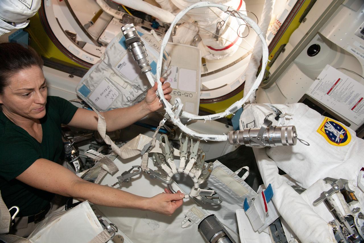
iss068e040900 (Jan. 19, 2023) --- NASA astronaut and Expedition 68 Flight Engineer Nicole Mann configures spacewalking hardware inside the International Space Station's Quest airlock.
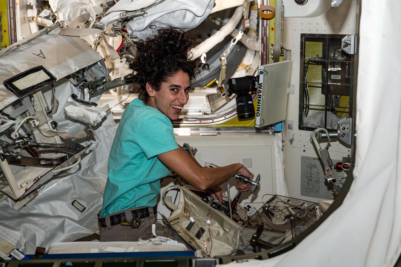
iss070e014310 (Oct. 27, 2023) --- NASA astronaut and Expedition 70 Flight Engineer Jasmin Moghbeli configures spacewalking tools inside the International Space Station's Quest airlock.
NASA Pilot Nils Larson wears a U.S. Air Force harness configuration with a helmet and an oxygen mask that is being used in the Pilot Breathing Assessment program at NASA's Armstrong Flight Research Center in California.
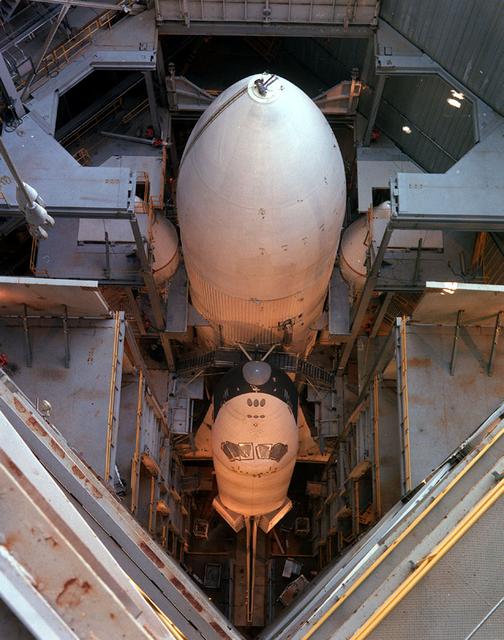
In its mated liftoff configuration of External Tank (ET) and Solid Rocket Boosters (SRB's), the Orbiter Enterprise (OV101) is pictured in the Marshall Space Flight Center Dynamic Test Stand for a Mated Vertical Ground Vibration Test (MVGVT).
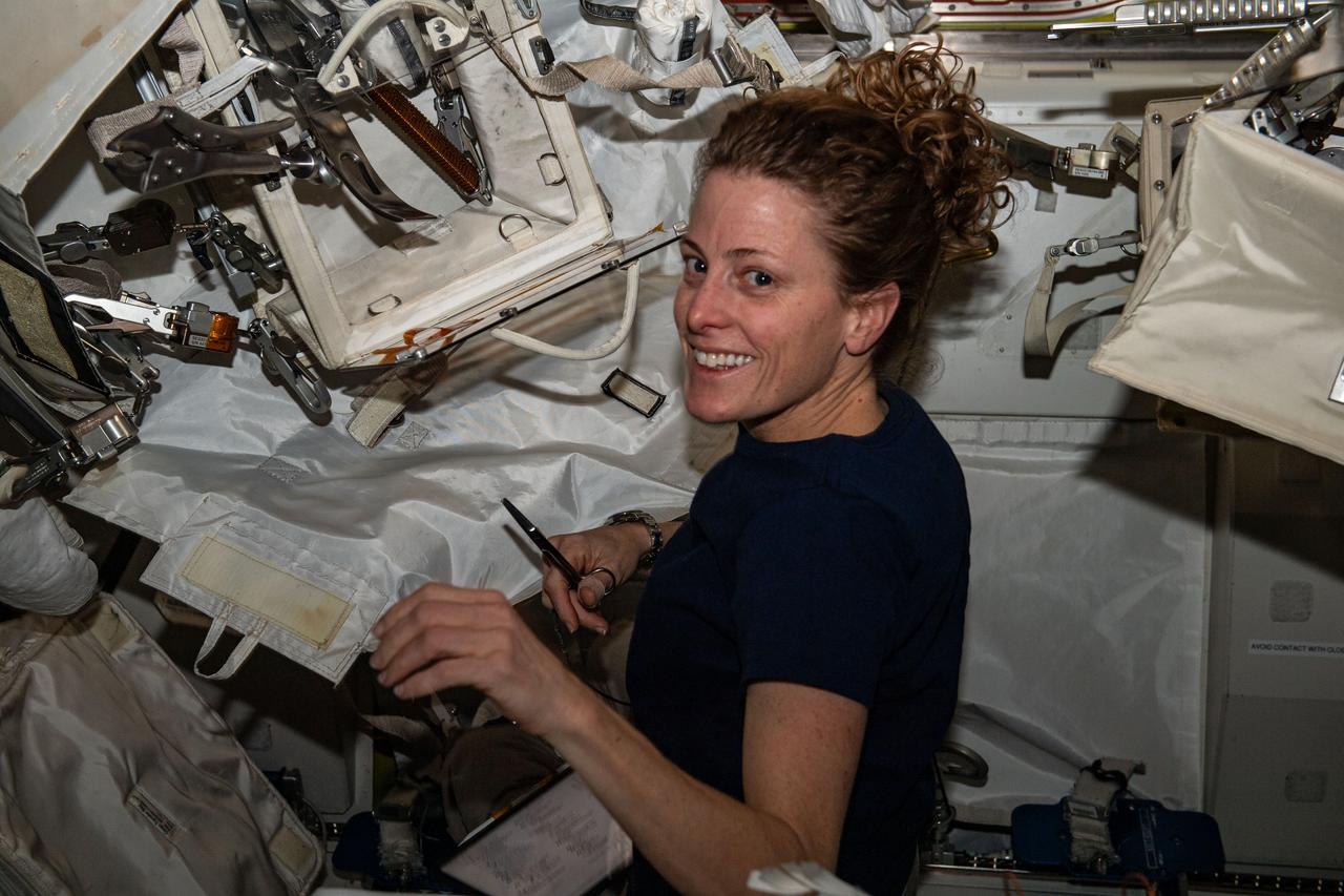
iss070e014316 (Oct. 27, 2023) --- NASA astronaut and Expedition 70 Flight Engineer Loral O'Hara configures spacewalking tools inside the International Space Station's Quest airlock.
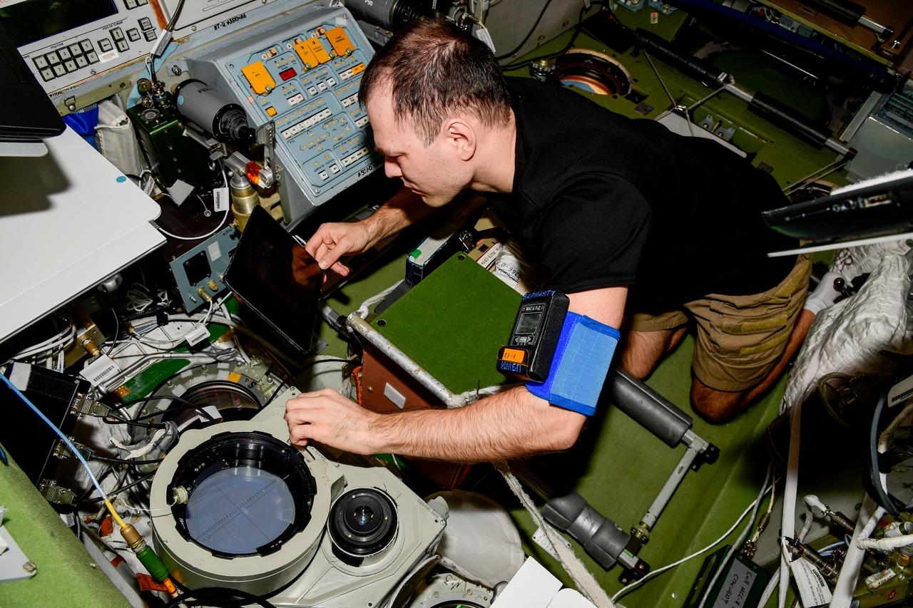
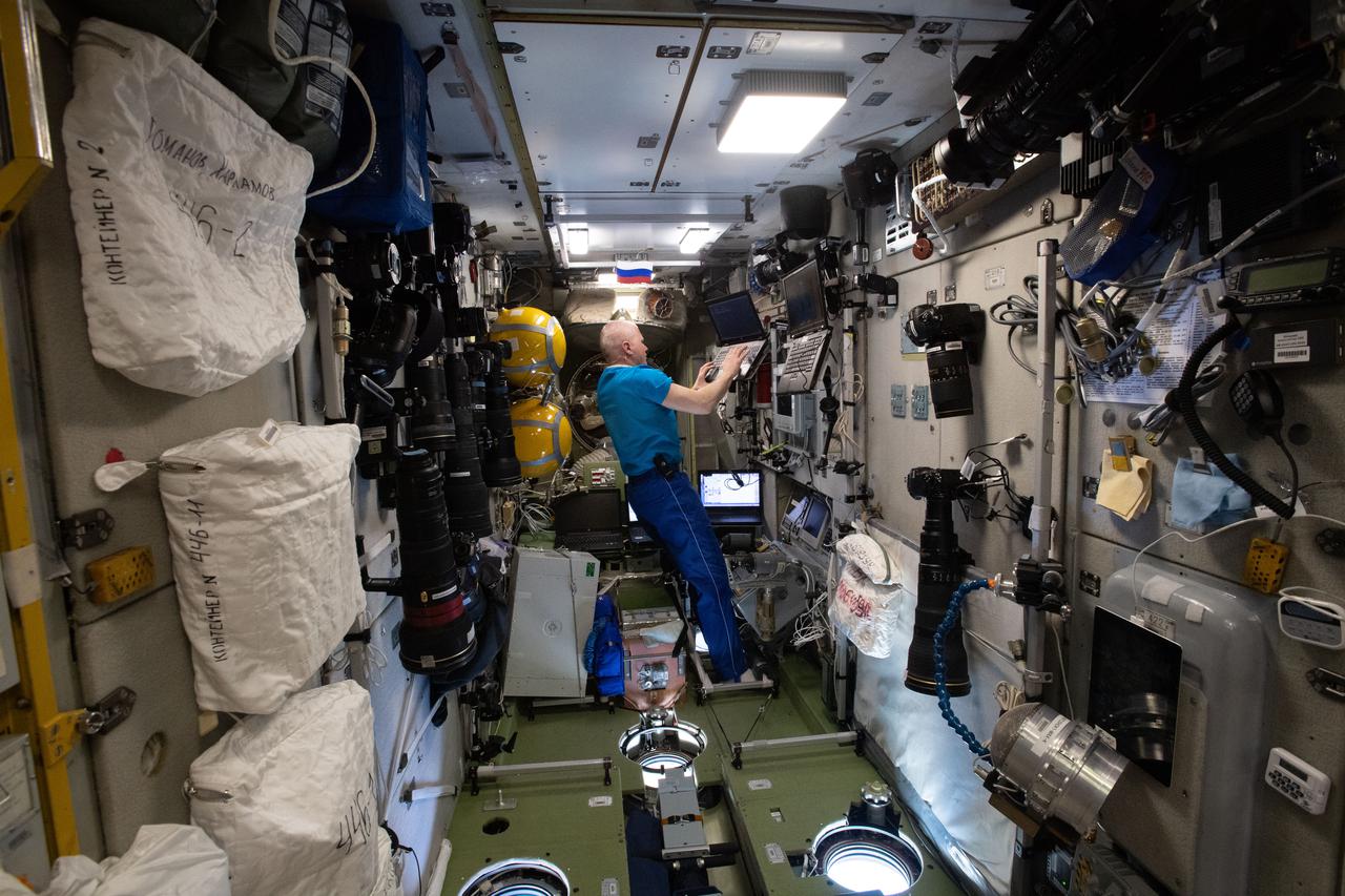
iss068e040003 (Jan. 11, 2023) --- Roscosmos cosmonaut and Expedition 68 Flight Engineer Dmitri Petelin configures optical hardware inside the International Space Station's Zvezda service module. Credit: Roscosmos
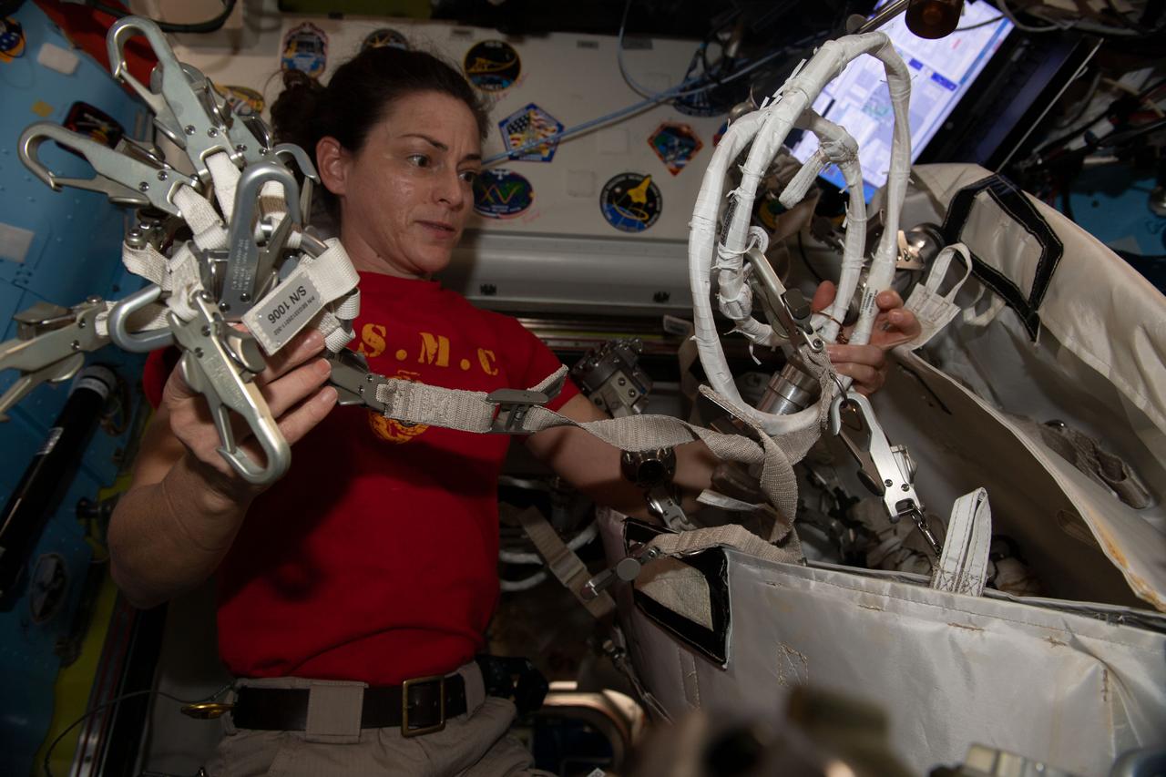
iss068e043086 (Jan. 27, 2023) --- NASA astronaut and Expedition 68 Flight Engineer Nicole Mann configures spacewalking hardware inside the International Space Station's Quest airlock.
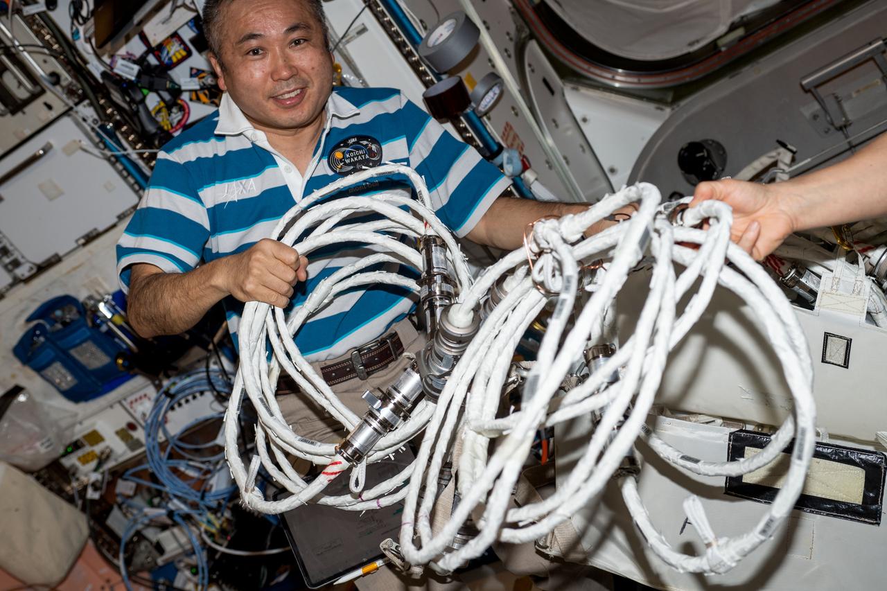
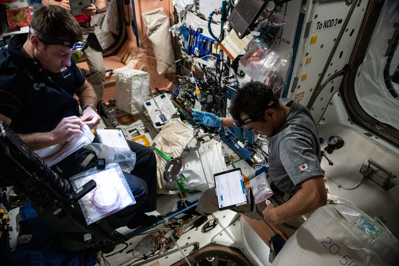
iss068e040899 (Jan. 19, 2023) --- Expedition 68 Flight Engineer Koichi Wakata of the Japan Aerospace Exploration Agency (JAXA) configures spacewalking hardware inside the International Space Station's Quest airlock.
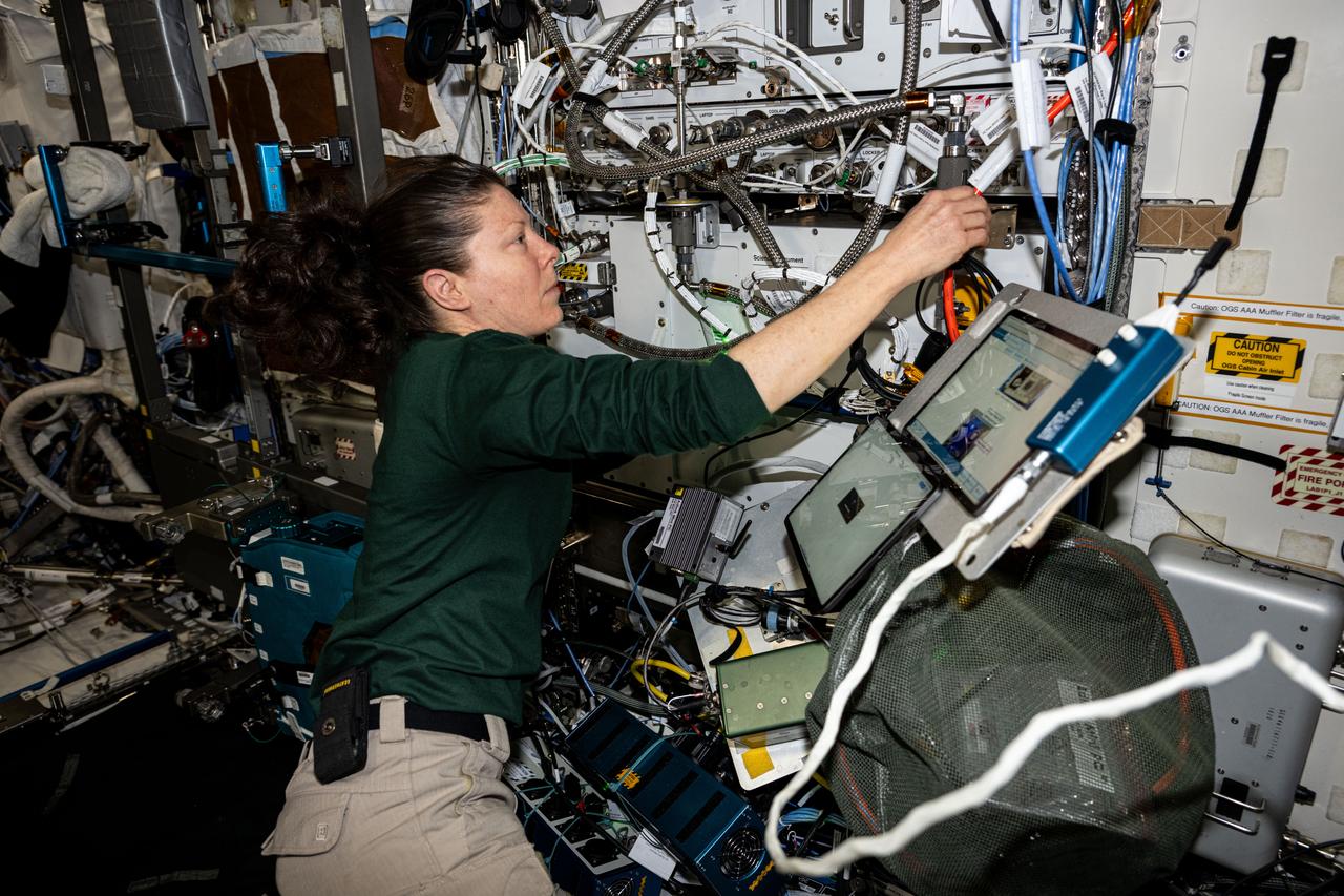
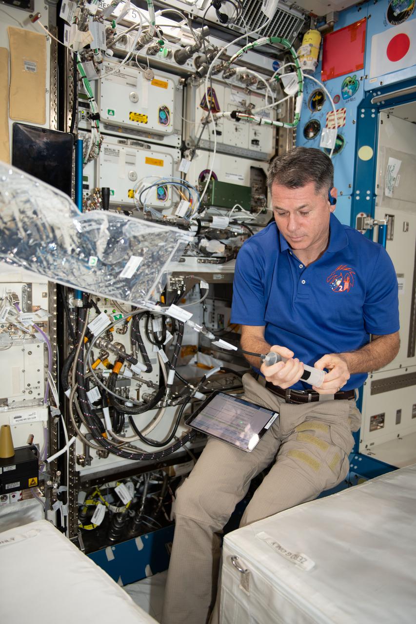
iss071e609375 (Sept. 5, 2024) --- NASA astronaut and Expedition 71 Flight Engineer Tracy C. Dyson tests the configuration of computers that control life support systems aboard the International Space Station's Destiny laboratory module.
iss071e523308 (Aug. 21, 2024) --- NASA astronaut and Commander for Boeing's Crew Flight Test Butch Wilmore checks CubeSat configurations packed inside launch cases installed in the Kibo laboratory module's Small Satellite Orbital Deployer.
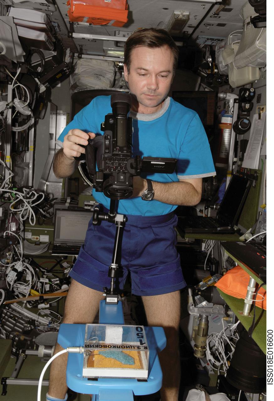
ISS018-E-016600 (5 Jan. 2009) --- Cosmonaut Yury Lonchakov, Expedition 18 flight engineer, configures a video camera for the MATI-75 experiment in the Zvezda Service Module of the International Space Station.
iss068e039915 (Jan. 11, 2023) --- NASA astronaut and Expedition 68 Flight Engineer Nicole Mann configures spacewalk tools and hardware inside the International Space Station's Destiny laboratory module.
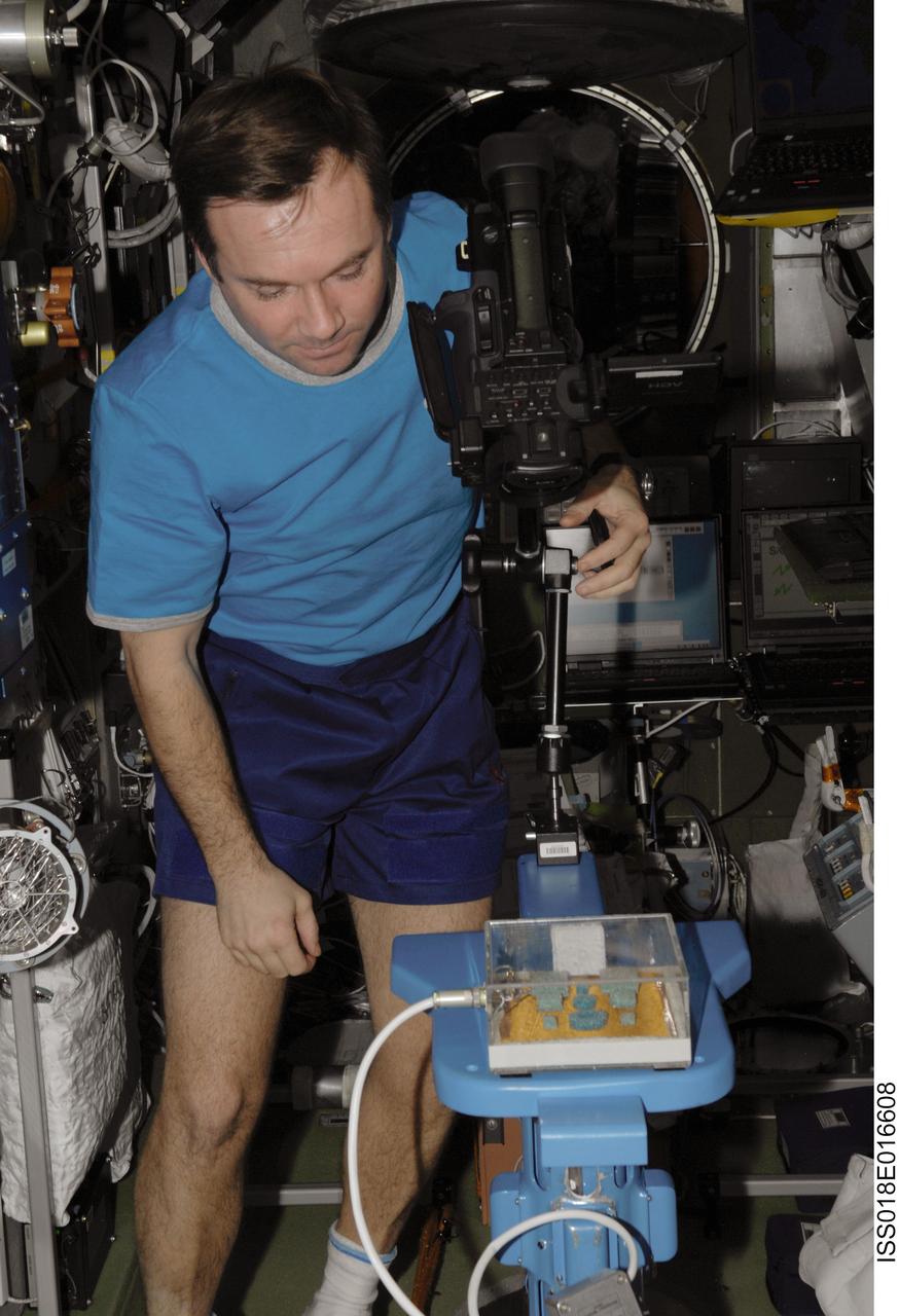
ISS018-E-016608 (5 Jan. 2009) --- Cosmonaut Yury Lonchakov, Expedition 18 flight engineer, configures a video camera for the MATI-75 experiment in the Zvezda Service Module of the International Space Station.

iss064e0221711 (Jan. 8, 2021) --- Flight Engineer Michael Hopkins works inside the Quest airlock configuring tools for planned spacewalks to continue maintenance on the outside of the International Space Station.
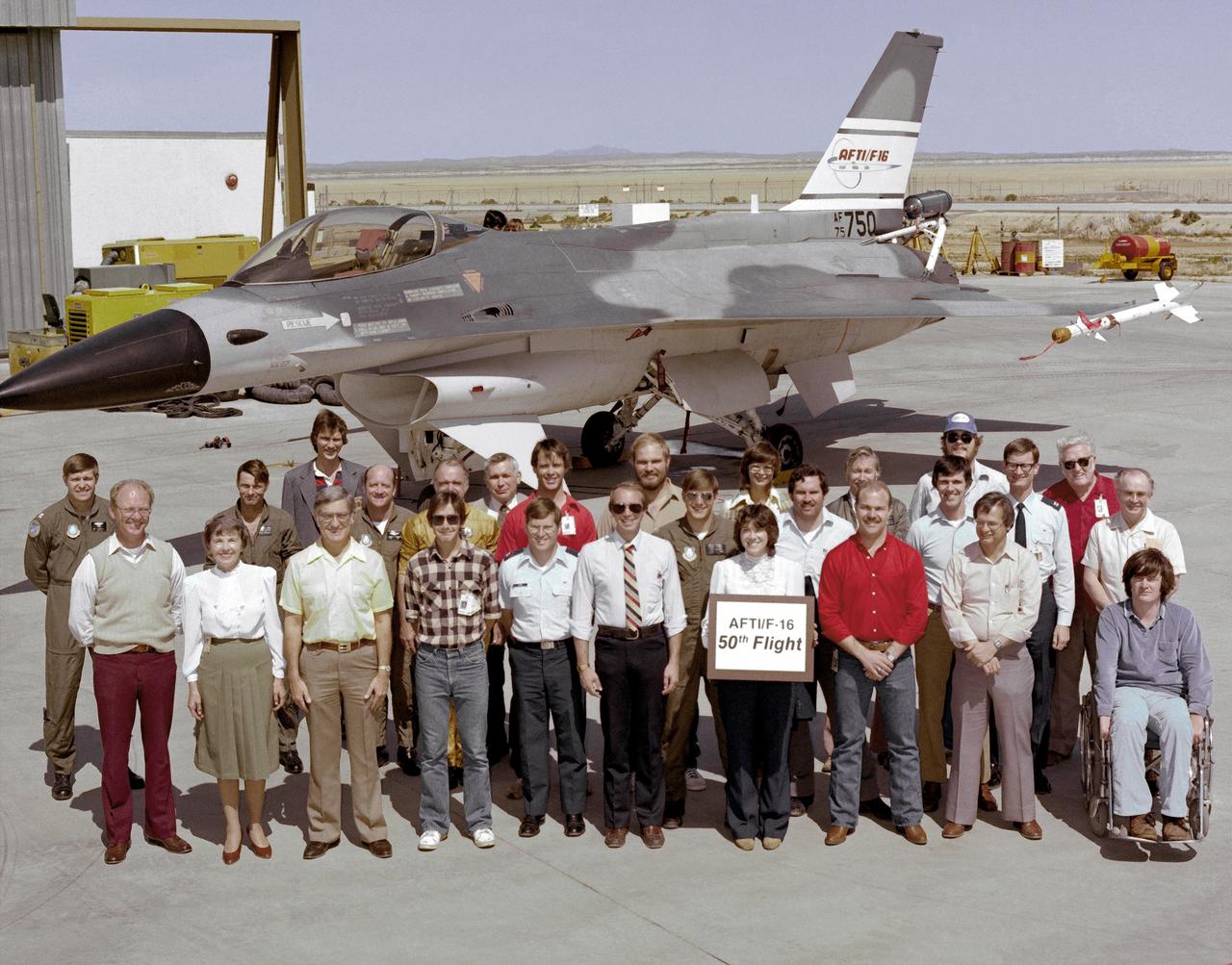
An early (1983) photograph of the AFTI F-16 team, commemorating the aircraft's 50th flight. It shows the initial configuration and paint finish of the AFTI F-16, as well as the forward mounted canards and the spin chute.
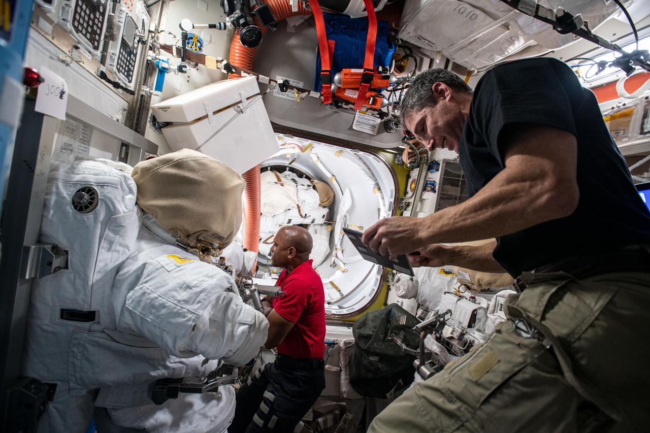
iss064e0221696 (Jan. 8, 2021) --- Flight Engineers Michael Hopkins (foreground) and Victor Glover configure tools inside the Quest airlock for planned spacewalks to continue maintenance on the outside of the International Space Station.
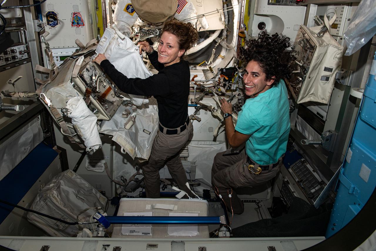
iss070e014305 (Oct. 27, 2023) --- Expedition 70 Flight Engineers (from left) Loral O'Hara and Jasmin Moghbeli, both NASA astronauts, configure spacewalking tools inside the International Space Station's Quest airlock.
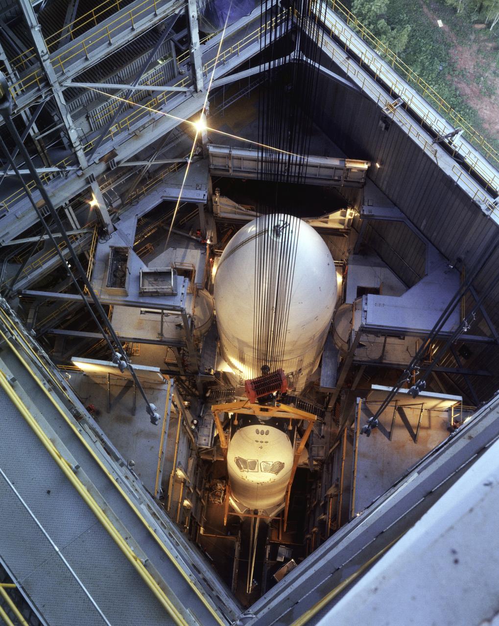
This photograph was taken of the Orbiter Enterprise installation, in its liftoff configuration, into the Marshall Space Flight Center Dynamic Test Stand for a Mated Vertical Ground Vibration Test (MVGVT).
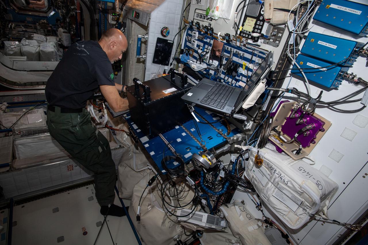
iss060e032989 (Aug. 9, 2019) --- Expedition 60 Flight Engineer Luca Parmitano of the European Space Agency configures and installs hardware in the Fluid Science Laboratory to continue ongoing fluid physics research in microgravity.
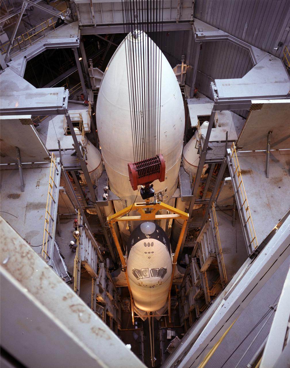
This photograph was taken at the Orbiter Enterprise installation, in its liftoff configuration, into the Marshall Space Flight Center Dynamic Test Stand for a Mated Vertical Ground Vibration Test (MVGVT).
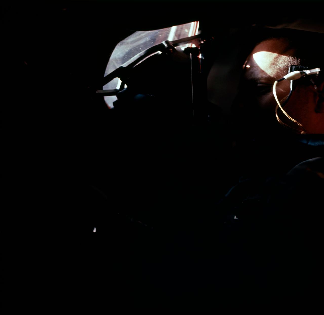
S65-45610 (21 Aug. 1965) --- Astronaut Charles Conrad Jr. as seen through the Gemini-5 spacecraft window before launch.
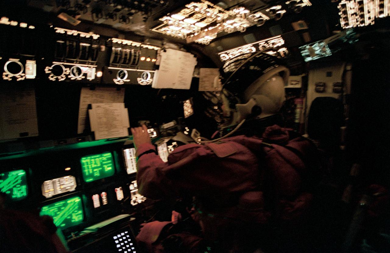
STS062-41-025 (18 March 1994) --- Astronaut Andrew M. Allen monitors Columbia's systems from the pilot's station during the entry phase of the STS-62 mission. The fast-speed 35mm film highlights the many controls and displays and the cathode ray tubes on the forward flight deck.
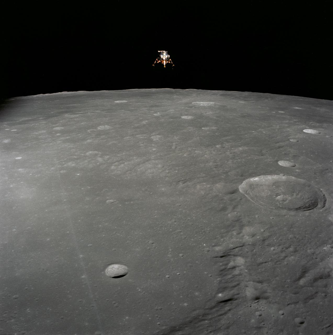
AS12-51-7507 (19 Nov. 1969) --- The Apollo 12 Lunar Module (LM), in a lunar landing configuration, is photographed in lunar orbit from the Command and Service Modules (CSM). The coordinates of the center of the lunar surface shown in picture are 4.5 degrees west longitude and 7 degrees south latitude. The largest crater in the foreground is Ptolemaeus; and the second largest is Herschel. Aboard the LM were astronauts Charles Conrad Jr., commander; and Alan L. Bean, lunar module pilot. Astronaut Richard R. Gordon Jr., command module pilot, remained with the CSM in lunar orbit while Conrad and Bean descended in the LM to explore the surface of the moon. Photo credit: NASA
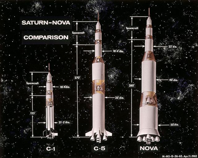
In this 1962 artist's concept , a proposed Nova rocket, shown at right, is compared to a Saturn C-1, left, and a Saturn C-5, center. The Marshall Space Flight Center directed studies of Nova configuration from 1960 to 1962 as a means of achieving a marned lunar landing with a direct flight to the Moon. Various configurations of the vehicle were examined, the largest being a five-stage vehicle using eight F-1 engines in the first stage. Although the program was effectively cancelled in 1962 when NASA planners selected the lunar-orbital rendezvous mode, the proposed F-1 engine was eventually used to propel the first stage of the Saturn V launch vehicle in the Apollo Program.
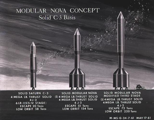
This artist's concept illustrates the Module Nova concept - Solid C-3 Basis. From 1960 to 1962, the Marshall Space Flight Center considered the Nova launch vehicle as a means to achieve a marned lunar landing with a direct flight to the Moon. Various configurations of the vehicle were examined. The latest configuration was a five-stage vehicle using eight F-1 engines in the first stage. Although the program was canceled after NASA planners selected the lunar/orbital rendezvous mode, the proposed F-1 engine would eventually be used in the Apollo Program to propel the first stage of the Saturn V launch vehicle.
This artist's concept illustrates the Module Nova concept - Solid C-3 Basis. From 1960 to 1962, the Marshall Space Flight Center considered the Nova launch vehicle as a means to achieve a marned lunar landing with a direct flight to the Moon. Various configurations of the vehicle were examined. The latest configuration was a five-stage vehicle using eight F-1 engines in the first stage. Although the program was canceled after NASA planners selected the lunar/orbital rendezvous mode, the proposed F-1 engine would eventually be used in the Apollo Program to propel the first stage of the Saturn V launch vehicle.
iss071e523320 (Aug. 21, 2024) --- NASA astronauts (from left) Butch Wilmore, Commander for Boeing's Crew Flight Test, and Matthew Dominick, Expedition 71 Flight Engineer, check CubeSat configurations inside the Small Satellite Orbital Deployer aboard the International Space Station's Kibo laboratory module.
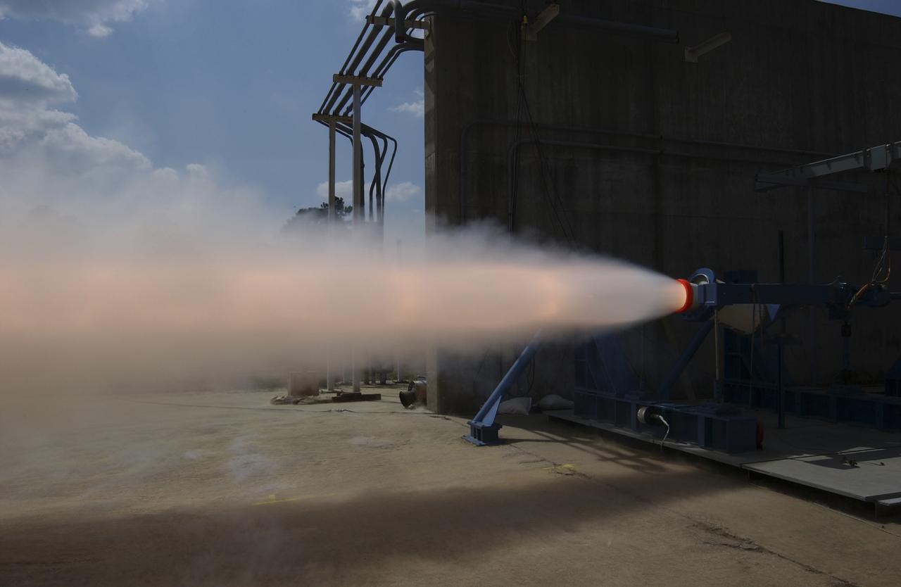
This photograph depicts a hot fire test of the Shuttle Booster Separation Motor (BSM) at the Marshall Space Flight Center (MSFC) test stand 116. The objective of the test was to test the aft heat seal in flight configuration. The function of the motor is to separate the Shuttle vehicle from the boosters that carry it into space.
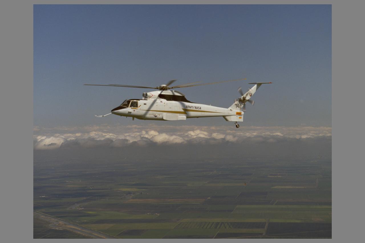
Sikorsky RSRA - Rotor Systems Research Aircraft (72-002 NASA 741) in helicopter configuration flight. Note: Used in publication in Flight Research at Ames; 57 Years of Development and Validation of Aeronautical Technology NASA SP-1998-3300 fig. 131
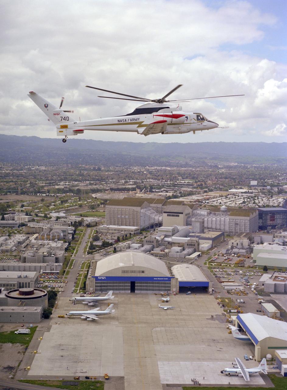
Sikorsky Rotor Systems Research Aircraft ' RSRA' (72-001 NASA-740) compound configuration in flight: NASA Ames Research Center, Hangar and 40x 80x120ft W.T. in the background. Note: Used in publication in Flight Research at Ames; 57 Years of Development and Validation of Aeronautical Technology NASA SP-1998-3300 fig. 132
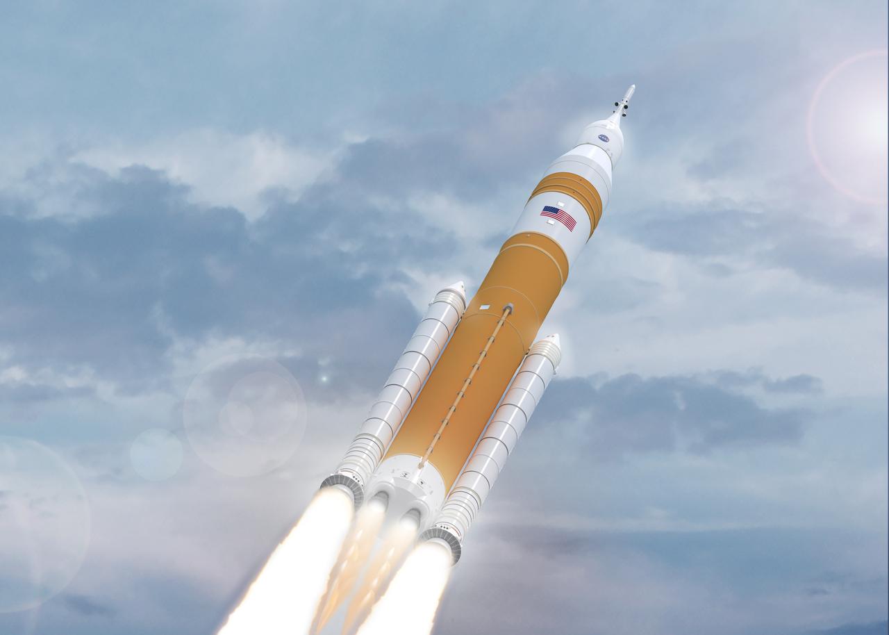
Illustration of evolved SLS Block 1B Crew variant in flight. This configuration of the rocket, with the Exploration Upper Stage, will provide in-space propulsion to send astronauts in NASA’s Orion spacecraft and heavy cargo on a precise trajectory to the Moon. The evolution of the rocket to SLS Block 1B configuration with EUS enables SLS to launch 40% more cargo to the Moon along with the crew. Manufacturing both the core stage and Exploration Upper Stage is a collaborative effort between NASA and Boeing, the lead contractor for EUS and the SLS core stage. SLS is the only rocket that can send Orion, astronauts, and supplies to the Moon in a single mission. The SLS rocket, NASA’s Orion spacecraft, Gateway, and human landing system are part of NASA’s backbone for deep space exploration. Under the Artemis program, NASA is working to land the first woman and the next man on the Moon to pave the way for sustainable exploration at the Moon and future missions to Mars. (NASA)
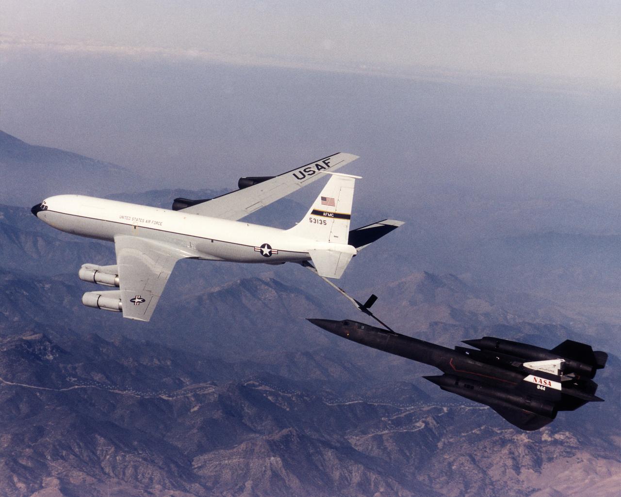
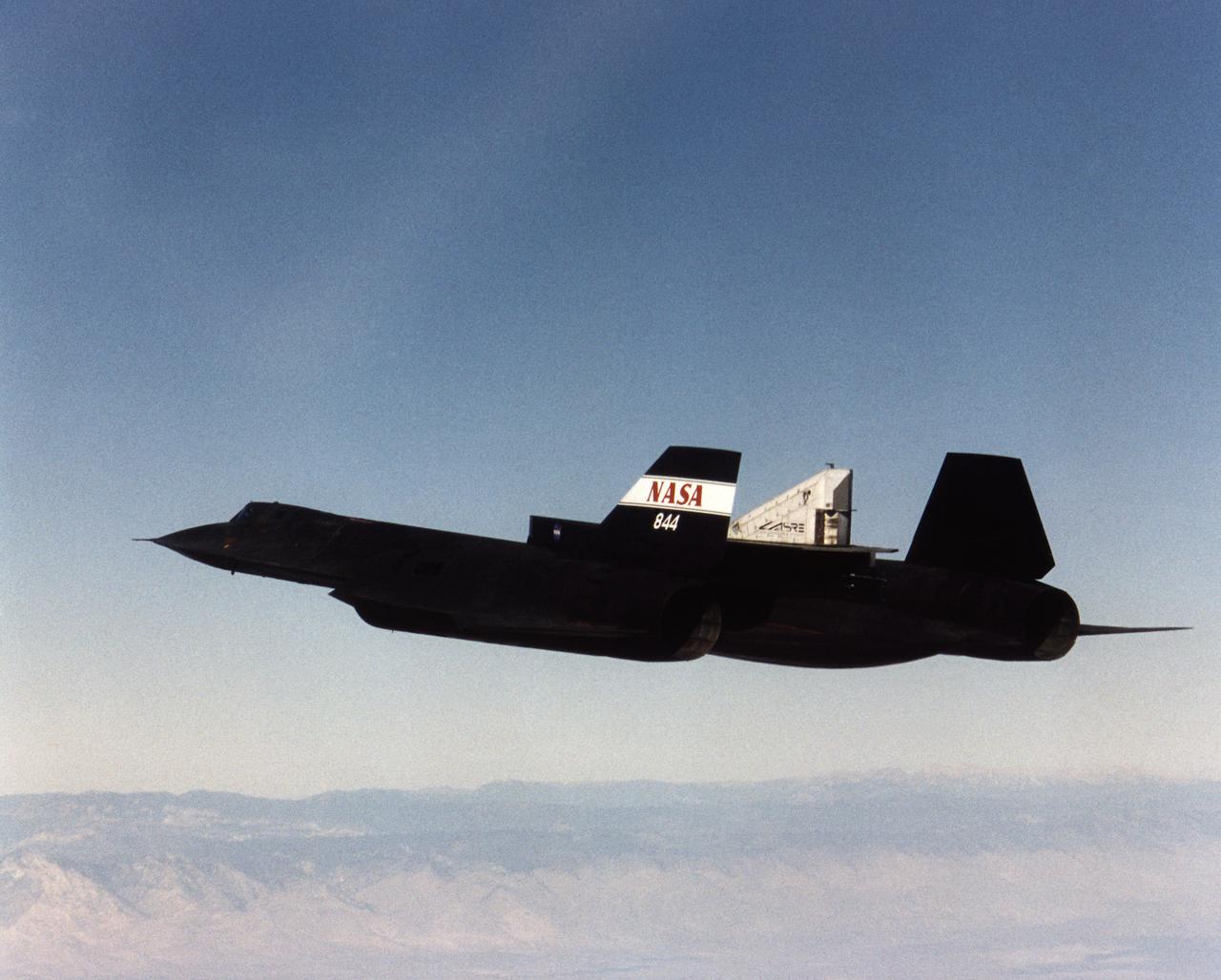
A NASA SR-71 refuels with an Edwards Air Force Base KC-135 during the first flight of the NASA/Rocketdyne/ Lockheed Martin Linear Aerospike SR-71 Experiment (LASRE). The flight took place Oct. 31 at NASA's Dryden Flight Research Center, Edwards, California. The SR-71 took off at 8:31 a.m. PST. The aircraft flew for one hour and fifty minutes, reaching a maximum speed of Mach 1.2 before landing at Edwards at 10:21 a.m. PST, successfully validating the SR-71/linear aerospike experiment configuration. The goal of the first flight was to evaluate the aerodynamic characteristics and the handling of the SR-71/linear aerospike experiment configuration. The engine was not fired during the flight.
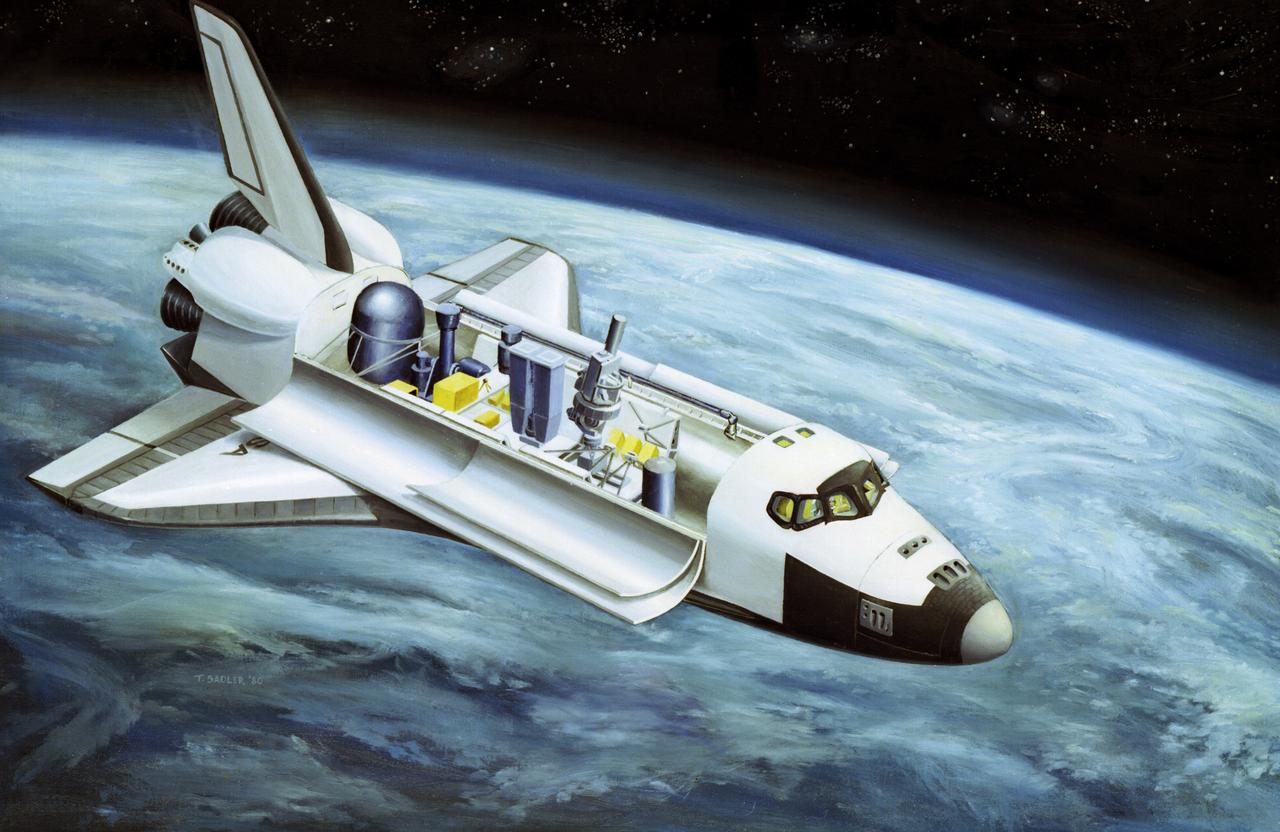
This illustration depicts the configuration of the Spacelab-2 in the cargo bay of the orbiter. Spacelab was a versatile laboratory carried in the Space Shuttle's cargo bay for scientific research flights. Each Spacelab mission had a unique design appropriate to the mission's goals. A number of Spacelab configurations could be assembled from pressurized habitation modules and exposed platforms called pallets. Spacelab-2 was the first pallet-only mission. One of the goals of the mission was to verify that the pallets' configuration was satisfactory for observations and research. Except for two biological experiments and an experiment that used ground-based instruments, the Spacelab-2 scientific instruments needed direct exposure to space. On the first pallet, three solar instruments and one atmospheric instrument were mounted on the Instrument Pointing System, which was being tested on its first flight. The second Spacelab pallet held a large double x-ray telescope and three plasma physics detectors. The last pallet supported an infrared telescope, a superfluid helium technology experiment, and a small plasma diagnostics satellite. The Spacelab-2 mission was designed to capitalize on the Shuttle-Spacelab capabilities, to launch and retrieve satellites, and to point several instruments independently with accuracy and stability. Spacelab-2 (STS-51F, 19th Shuttle mission) was launched aboard Space Shuttle Orbiter Challenger on July 29, 1985. The Marshall Space Flight Center had overall management responsibilities of the Spacelab missions.
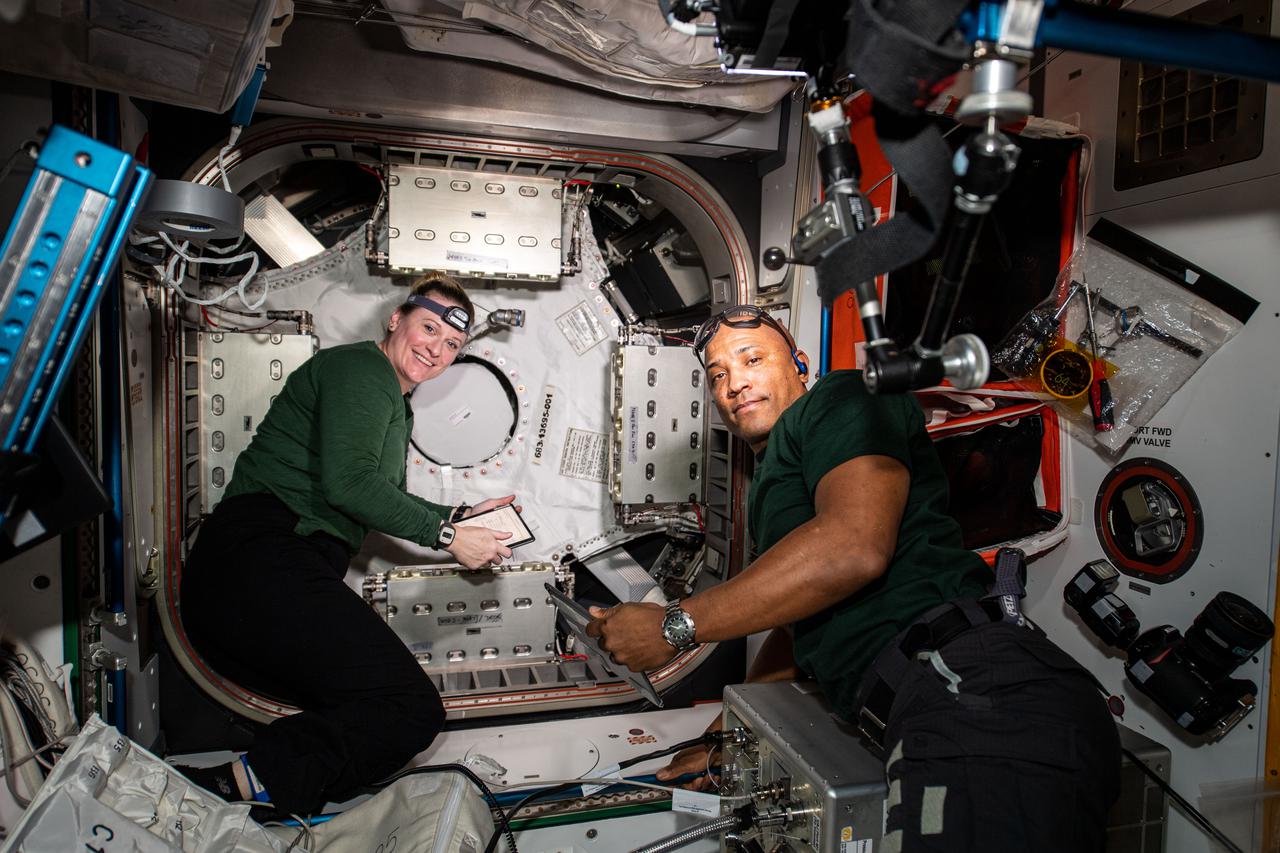
iss064e030013 (Feb. 8, 2021) --- NASA astronauts and Expedition 64 Flight Engineers Kate Rubins and Victor Glover work to configure and open the NanoRacks Bishop airlock attached to the Tranquility module. Bishop will enable more commercial research, satellite deployments, and cargo operations outside in the vacuum of space.
iss065e163206 (June 9, 2021) --- NASA astronaut and Expedition 65 Flight Engineer Shane Kimbrough configures the Advanced Plant Habitat and fills it with water to support the Plant Habitat-04 space botany experiment. The study is demonstrating growing peppers, which are an excellent source of vitamin C, in space for the first time.
iss065e349549 (Sept. 4, 2021) --- Roscosmos cosmonaut and Expedition 65 Flight Engineer Oleg Novitskiy is in the Zvezda service module the day after a spacewalk that he and fellow cosmonaut Pyotr Dubrov conducted to begin configuring the Nauka multipurpose laboratory module for science operations.
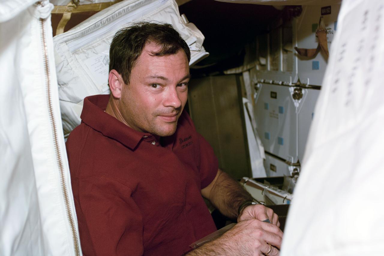
S92-E-5026 (12 October 2000) --- Astronaut Michael Lopez-Alegria, one of four STS-92 crew members who are participating in the four scheduled space walks designed to put final touches on the current ISS configuration for its first occupancy, was recorded by an electronic still camera (ESC) on Flight Day 2.
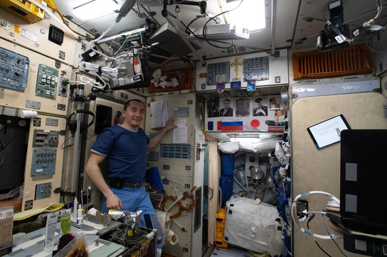
iss065e349552 (Sept. 4, 2021) --- Roscosmos cosmonaut and Expedition 65 Flight Engineer Pyotr Dubrov is in the Zvezda service module the day after a spacewalk that he and fellow cosmonaut Oleg Novitskiy conducted to begin configuring the Nauka multipurpose laboratory module for science operations
ISS030-E-210829 (6 April 2012) --- European Space Agency astronaut Andre Kuipers, Expedition 30 flight engineer, configures the Gas Control Panel (GCP) in the Automated Transfer Vehicle (ATV-3) currently docked with the International Space Station.
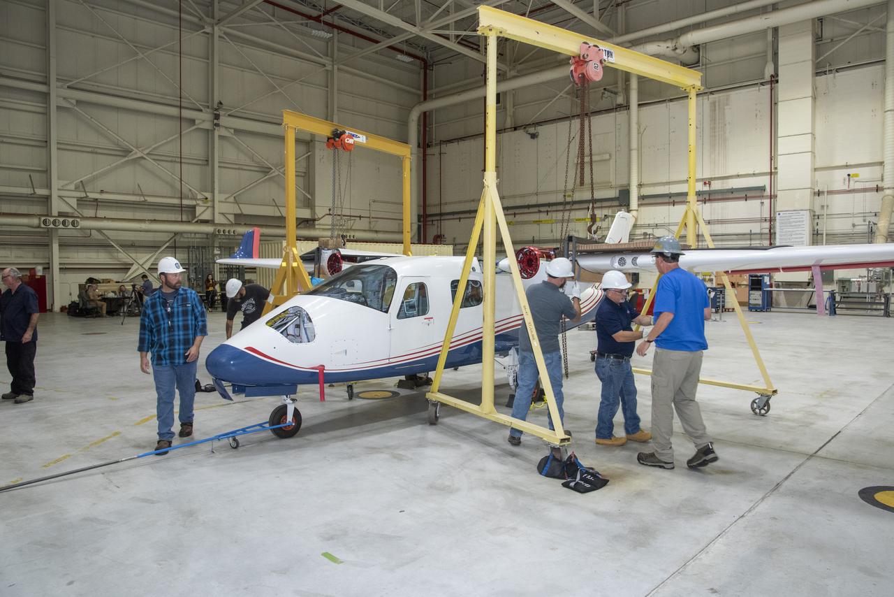
The X-57 Mod II wing is rejoined with the aircraft's fuselage to begin preparations for reintegration at NASA's Armstrong Flight Research Center in California. X-57's Mod II configuration, the first of three primary modifications for the project, involves testing of the aircraft's cruise electric propulsion system.
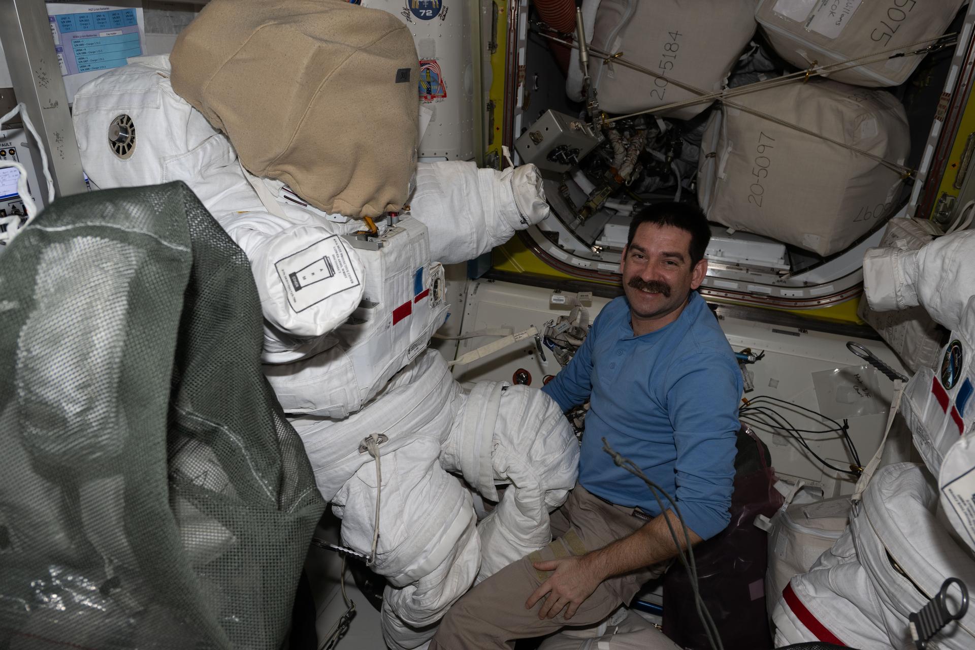
iss074e0350102 (March 3, 2026) --- NASA astronaut and Expedition 74 flight engineer Jack Hathaway configures a spacesuit installing its components, checking a helmet, and cleaning suit seals inside the International Space Station's Quest airlock. Credit: NASA/Jessica Meir
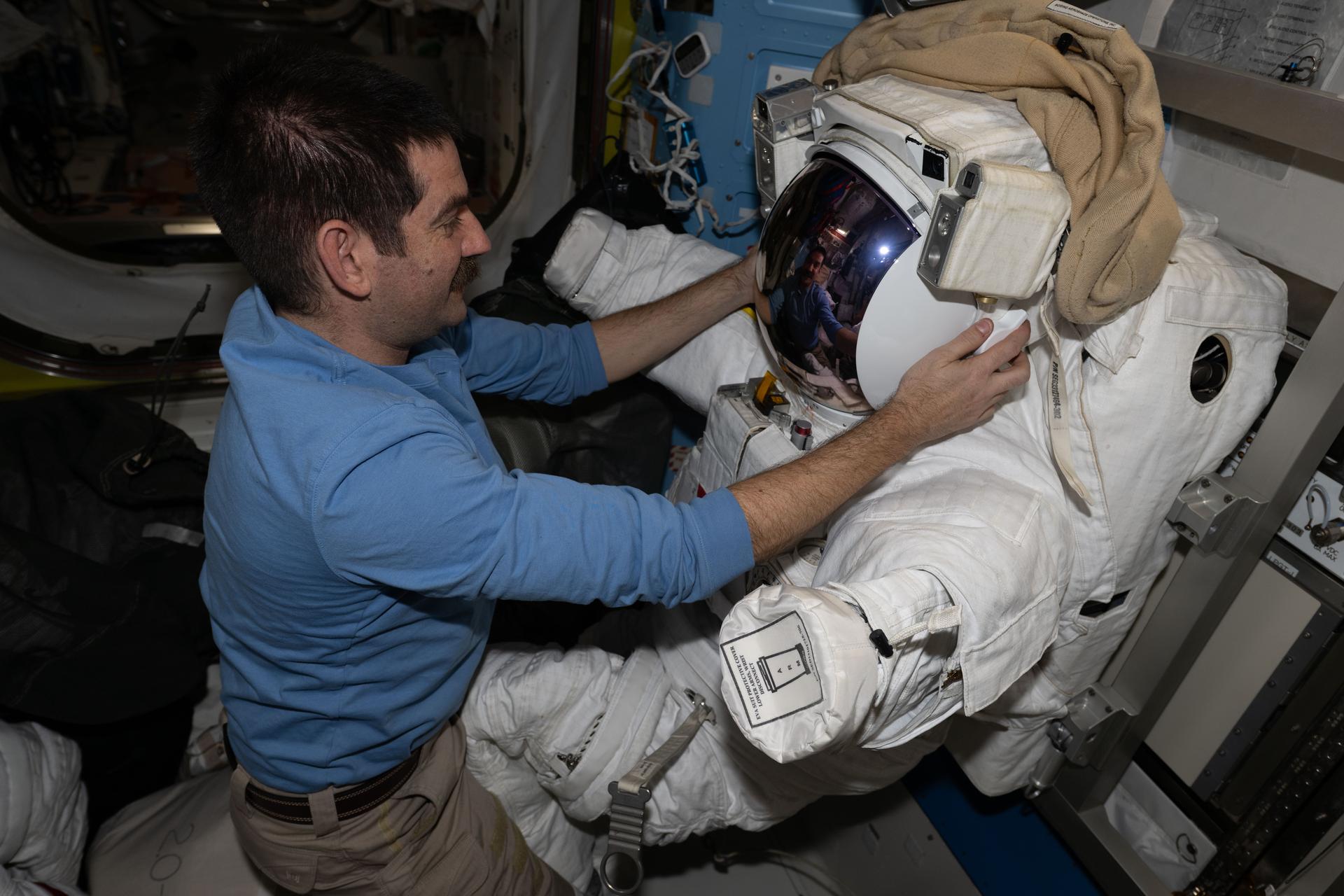
iss074e0350106 (March 3, 2026) --- NASA astronaut and Expedition 74 flight engineer Jack Hathaway configures a spacesuit installing its components, checking a helmet, and cleaning suit seals inside the International Space Station's Quest airlock. Credit: NASA/Jessica Meir
iss065e148860 (June 28, 2021) --- (From left) Expedition 65 Flight Engineer Thomas Pesquet of ESA (European Space Agency) and Commander Akihiko Hoshide of the Japan Aerospace Exploration Agency (JAXA) configure the vestibule in between the Unity module and the Northrop Grumman Cygnus space freighter the day before the U.S. cargo craft's departure.
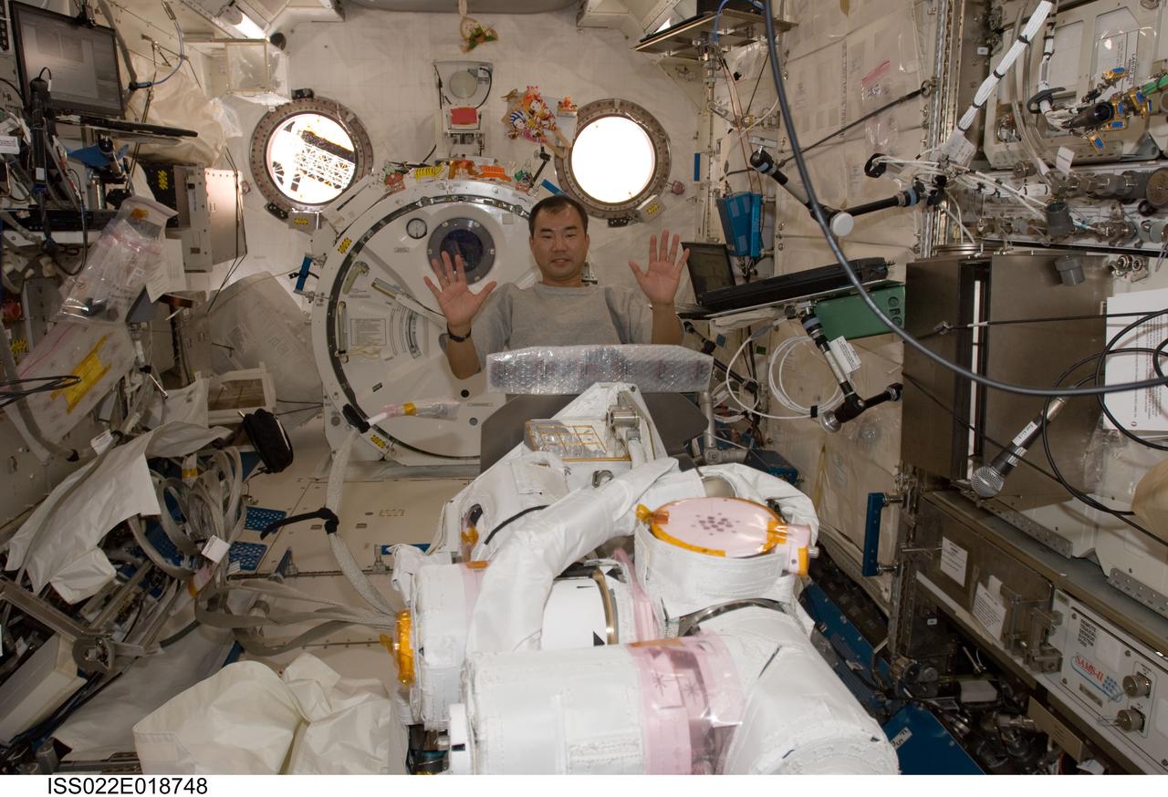
ISS022-E-018748 (5 Jan. 2010) --- Japan Aerospace Exploration Agency astronaut Soichi Noguchi, Expedition 22 flight engineer, assembles and configures the Japanese Experiment Module Remote Manipulator System (JEMRMS) Small Fine Arm (SFA) in the Kibo laboratory of the International Space Station.

iss071e414633 (July 31, 2024) --- NASA astronaut and Expedition 71 Flight Engineer Matthew Dominick is pictured wearing a spacesuit aboard the International Space Station's Quest airlock. Dominick was evaluating the spacesuit, configuring its components, and testing the suit’s communications and life support systems.
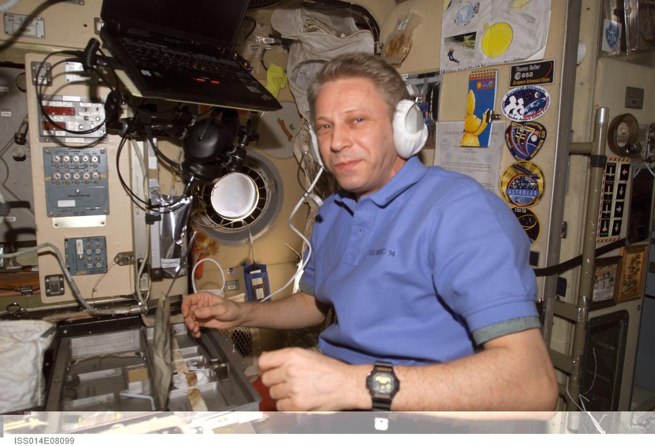
ISS014-E-08099 (22 Nov. 2006) --- European Space Agency (ESA) astronaut Thomas Reiter, Expedition 14 flight engineer, uses a communication system in the Zvezda Service Module of the International Space Station during a pre-EVA station onboard system configuration.
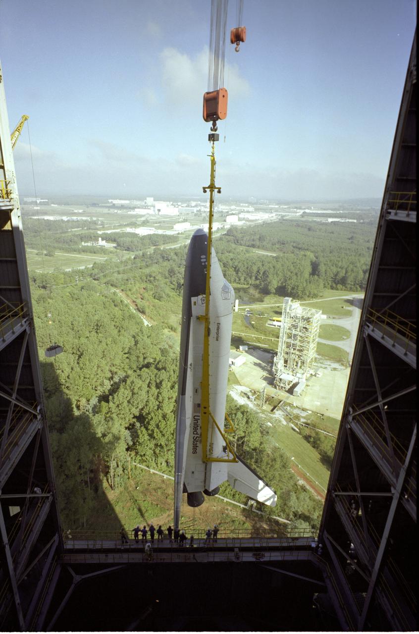
The Shuttle Orbiter Enterprise is being installed into liftoff configuration at Marshall Space Flight Center's Dynamic Test Stand for Mated Vertical Ground Vibration tests (MVGVT). The tests marked the first time ever that the entire shuttle complement (including Orbiter, external tank, and solid rocket boosters) were mated vertically.
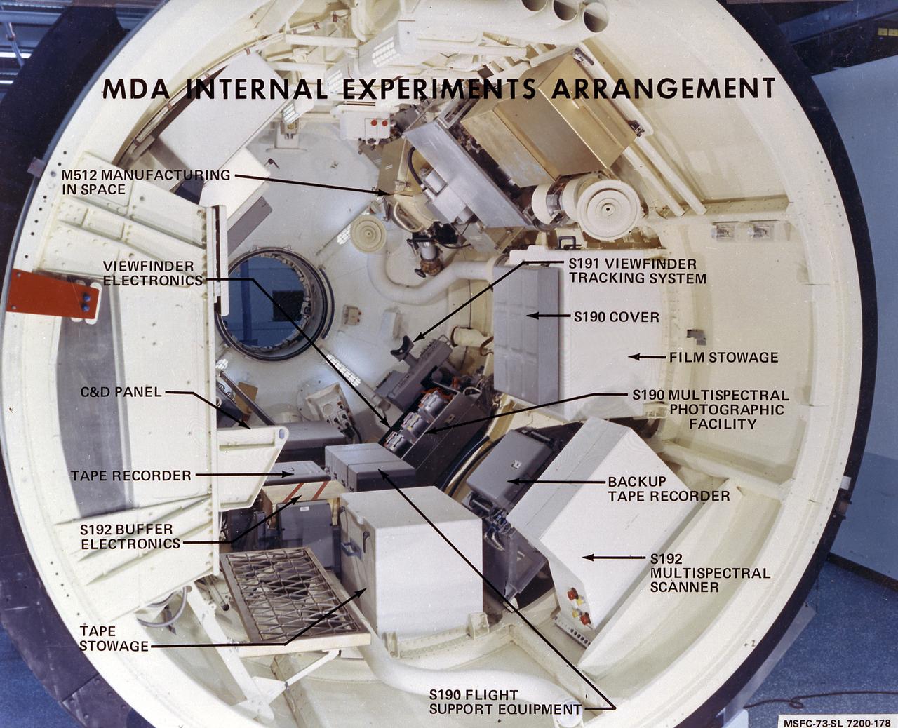
This photograph shows the internal configuration of Skylab's Multiple Docking Adapter (MDA), including callouts for its various internal experiments and facilities. Designed and manufactured by the Marshall Space Flight Center, the MDA housed a number of experiment control and stowage units and provided a docking port for the Apollo Command Module.

iss071e414639 (July 31, 2024) --- NASA astronaut and Expedition 71 Flight Engineer Matthew Dominick is pictured wearing a spacesuit aboard the International Space Station's Quest airlock. Dominick was evaluating the spacesuit, configuring its components, and testing the suit’s communications and life support systems.
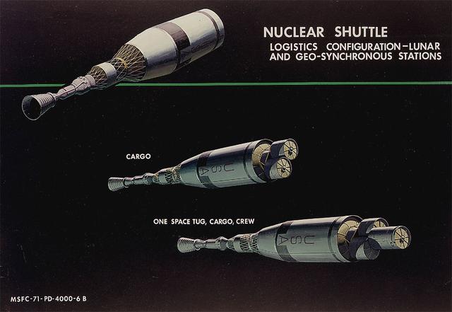
This 1971 artist's concept shows the Nuclear Shuttle in both its lunar logistics configuraton and geosynchronous station configuration. As envisioned by Marshall Space Flight Center Program Development persornel, the Nuclear Shuttle would deliver payloads to lunar orbits or other destinations then return to Earth orbit for refueling and additional missions.
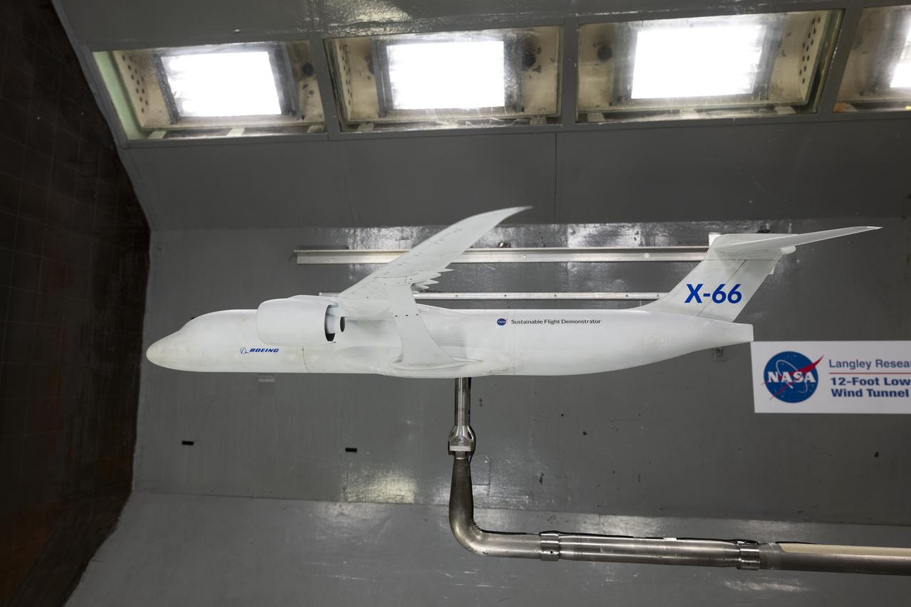
A model of the X-66 aircraft with a wingspan of almost 6 feet was placed in the 12-Foot Low-Speed Wind Tunnel at NASA’s Langley Research Center in Hampton, Virginia on October 30, 2024. During the tests, the team captured measurements of forces such as lift and drag over many aerodynamic configurations and flight conditions.

iss069e011049 (May 17, 2023) --- From left, Expedition 69 Flight Engineers Frank Rubio of NASA and Sultan Alneyadi of UAE (United Arab Emirates) return the station’s Treadmill 2 to its normal configuration inside the International Space Station's Tranquility module after an inspection and cleaning of its electronic components.
CAPE CANAVERAL, Fla. -- At the Kennedy Space Center in Florida, structural work is ongoing inside the high bay of the Operations and Checkout Building. The modifications are taking place to configure the facility flight hardware from the Apollo Program and prepare to support payload processing for future space shuttle missions. Photo Credit: NASA
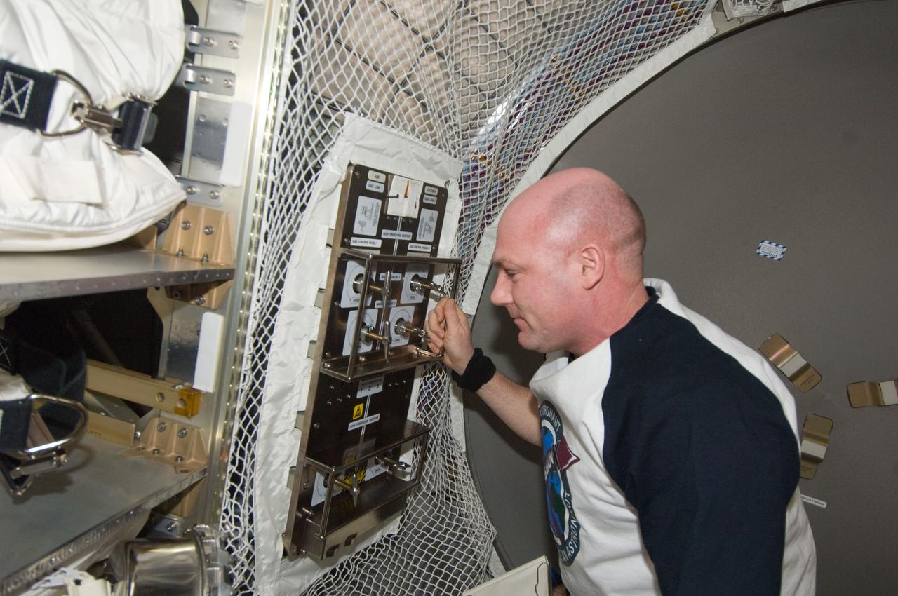
ISS030-E-210810 (6 April 2012) --- European Space Agency astronaut Andre Kuipers, Expedition 30 flight engineer, configures the Gas Control Panel (GCP) in the Automated Transfer Vehicle (ATV-3) currently docked with the International Space Station.
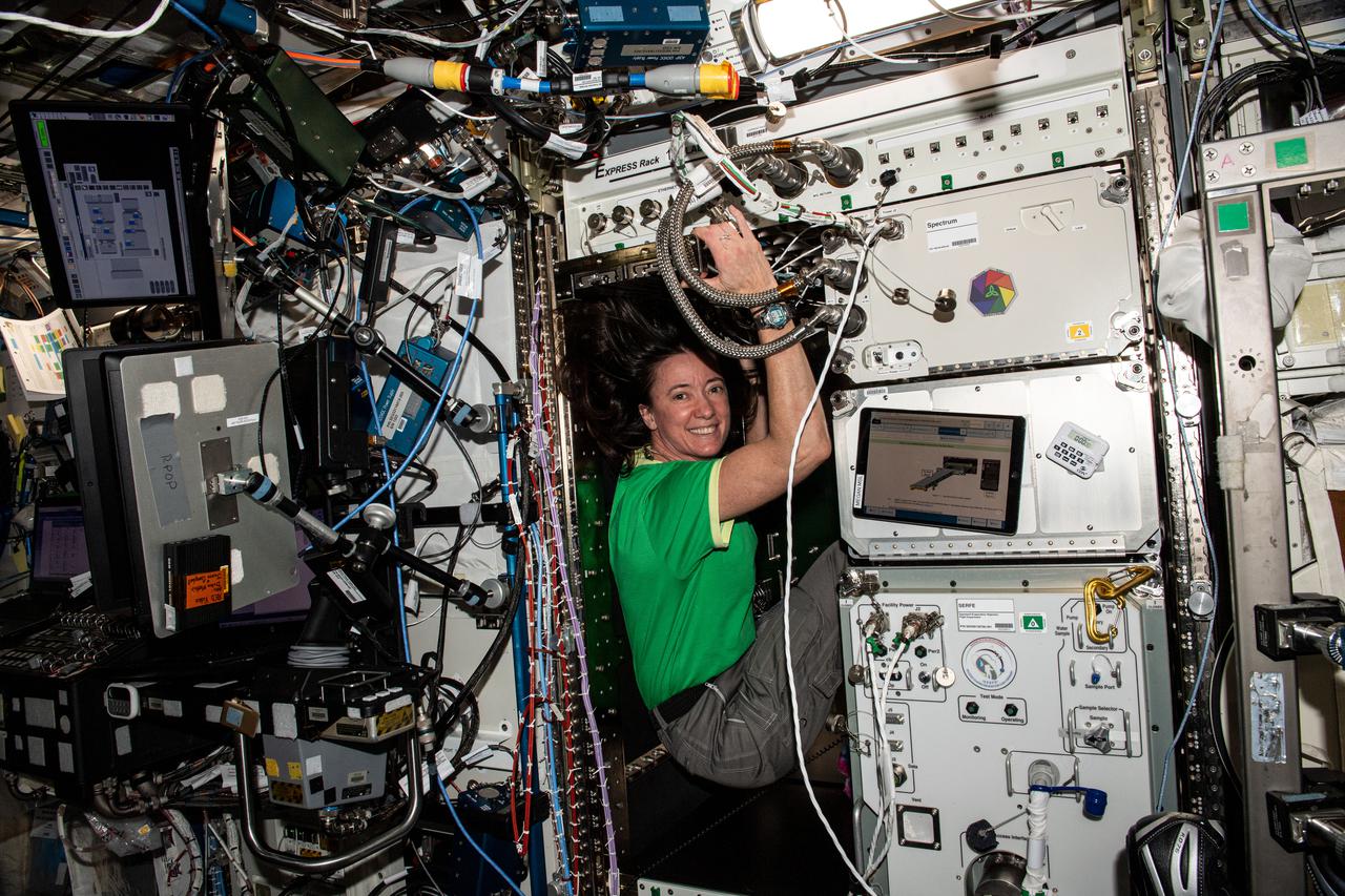
iss065e369753 (Sept. 9, 2021) --- NASA astronaut and Expedition 65 Flight Engineer Megan McArthur configures an EXPRESS rack inside the U.S. Destiny laboratory module before installing a new device that scrubs the International Space Station's atmosphere of carbon dioxide.
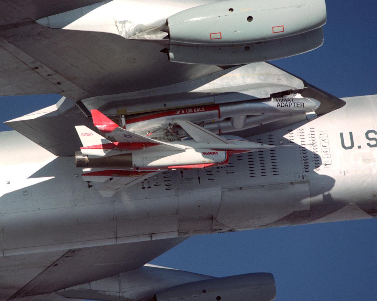
A close-up view of the Highly Maneuverable Aircraft Technology (HiMAT) research vehicle attached to a wing pylon on NASA’s B-52 mothership during a 1980 test flight. The HiMAT used sharply swept-back wings and a canard configuration to test possible technology for advanced fighters.
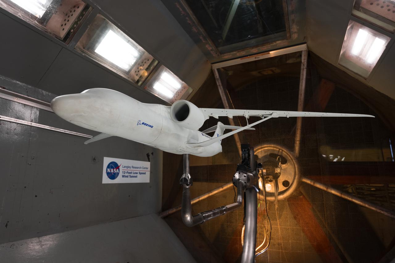
A model of the X-66 aircraft with a wingspan of almost 6 feet was placed in the 12-Foot Low-Speed Wind Tunnel at NASA’s Langley Research Center in Hampton, Virginia on October 30, 2024. During the tests, the team captured measurements of forces such as lift and drag over many aerodynamic configurations and flight conditions.