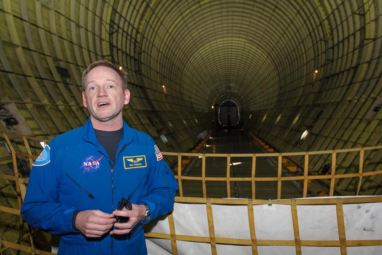
Super Guppy Flight Engineer Michael Robinson inside the Cargo Hold. The Super Guppy's cargo hold has a useable volume of 39,000 cubic feet and can fly up to 52,000 pounds as far as 564 miles and has a cruising speed of 290 MPH.
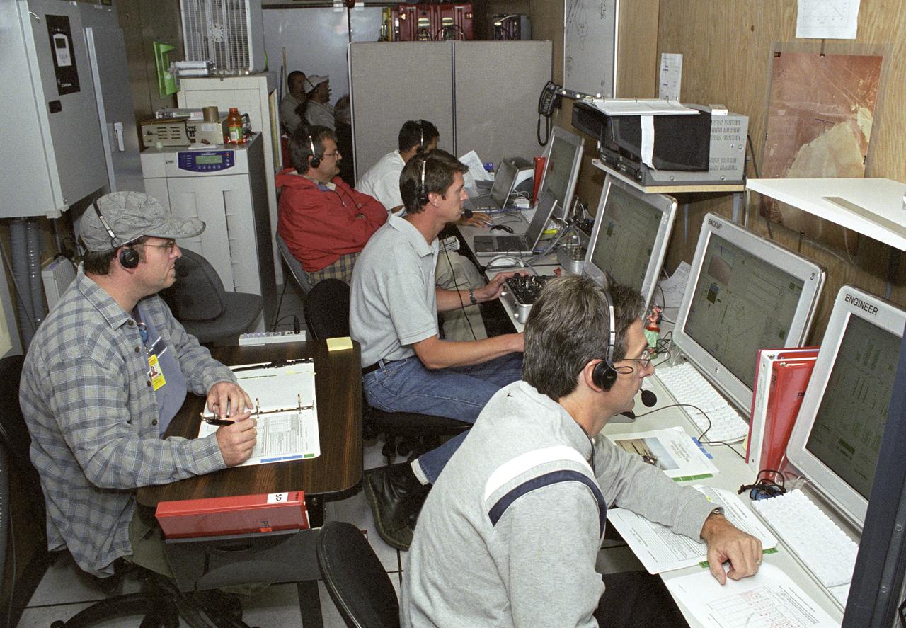
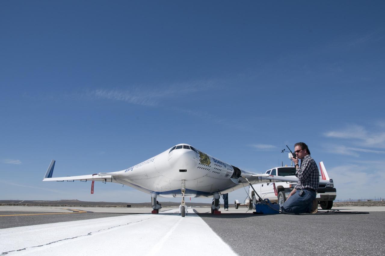
AeroVironment engineers and technicians closely monitor flight data in the ground control station during the Pathfinder-Plus' turbulence measurement flights.
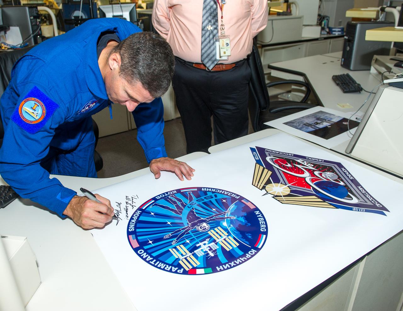
Flight Engineer of Expedition 37/38 Visits Goddard, NASA Astronaut Mike Hopkins
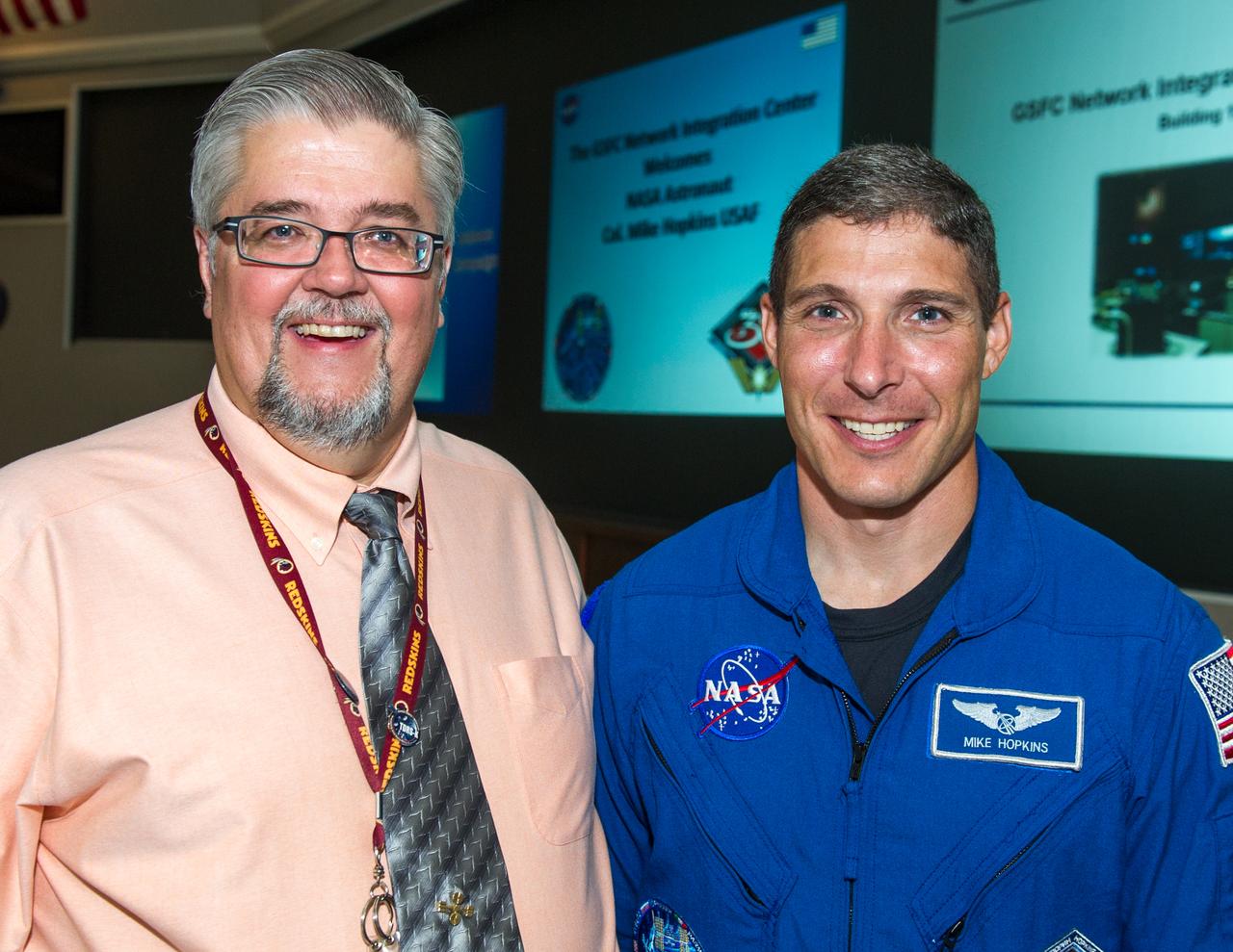
Flight Engineer of Expedition 37/38 Visits Goddard, NASA Astronaut Mike Hopkins
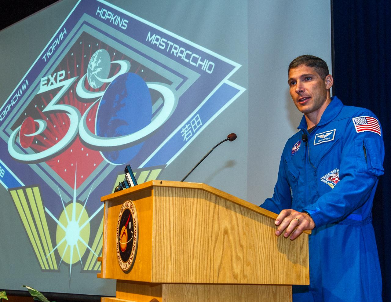
Flight Engineer of Expedition 37/38 Visits Goddard, NASA Astronaut Mike Hopkins
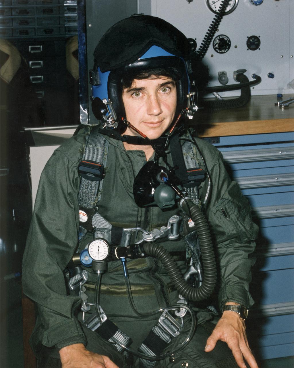
NASA Dryden flight test engineer Marta Bohn-Meyer is suited up for a research flight in the F-16XL laminar-flow control experiment in this 1993 photo.
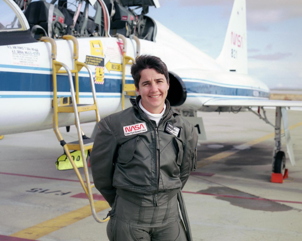
Marta Bohn-Meyer flew as a back-seat flight test engineer in this NASA T-38 mission support aircraft when this 1993 photo was taken.
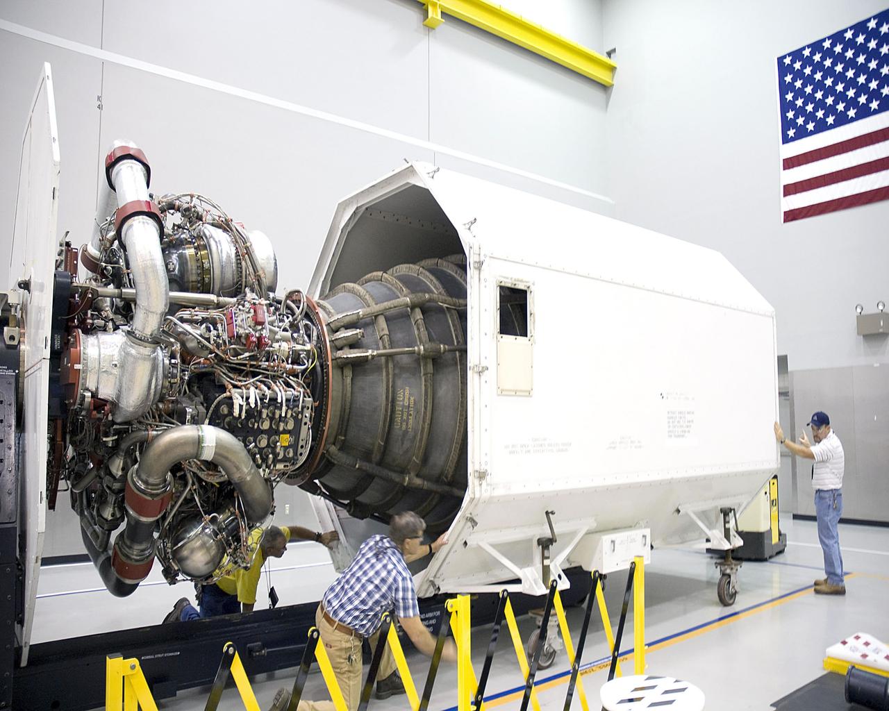
Workers at Stennis Space Center examine space shuttle main engine 2061 upon its arrival Oct. 1. The engine was to be the last shuttle flight engine to be scheduled for testing at Stennis.

Workers at Stennis Space Center examine space shuttle main engine 2061 upon its arrival Oct. 1. The engine was to be the last shuttle flight engine to be scheduled for testing at Stennis.
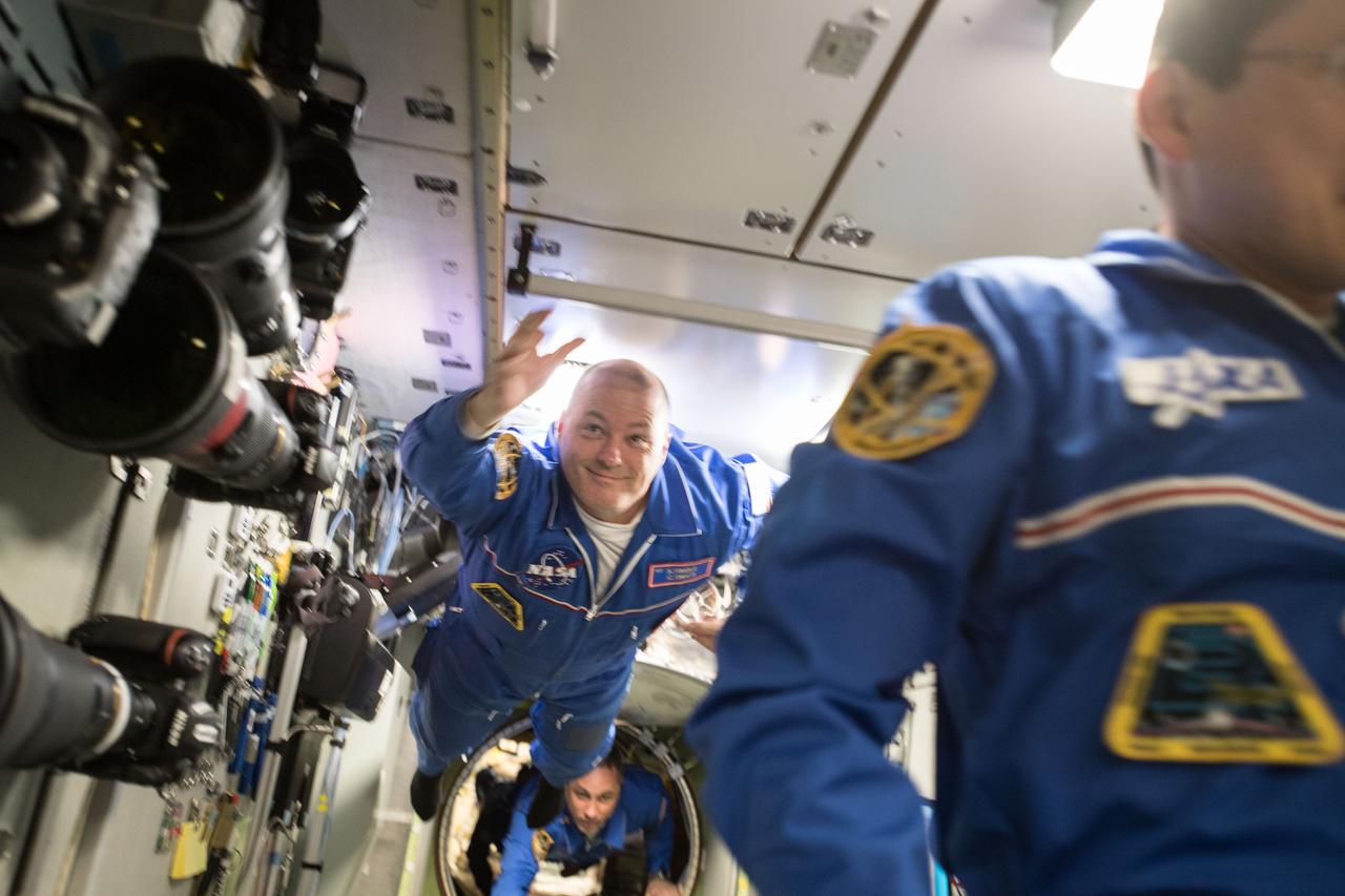
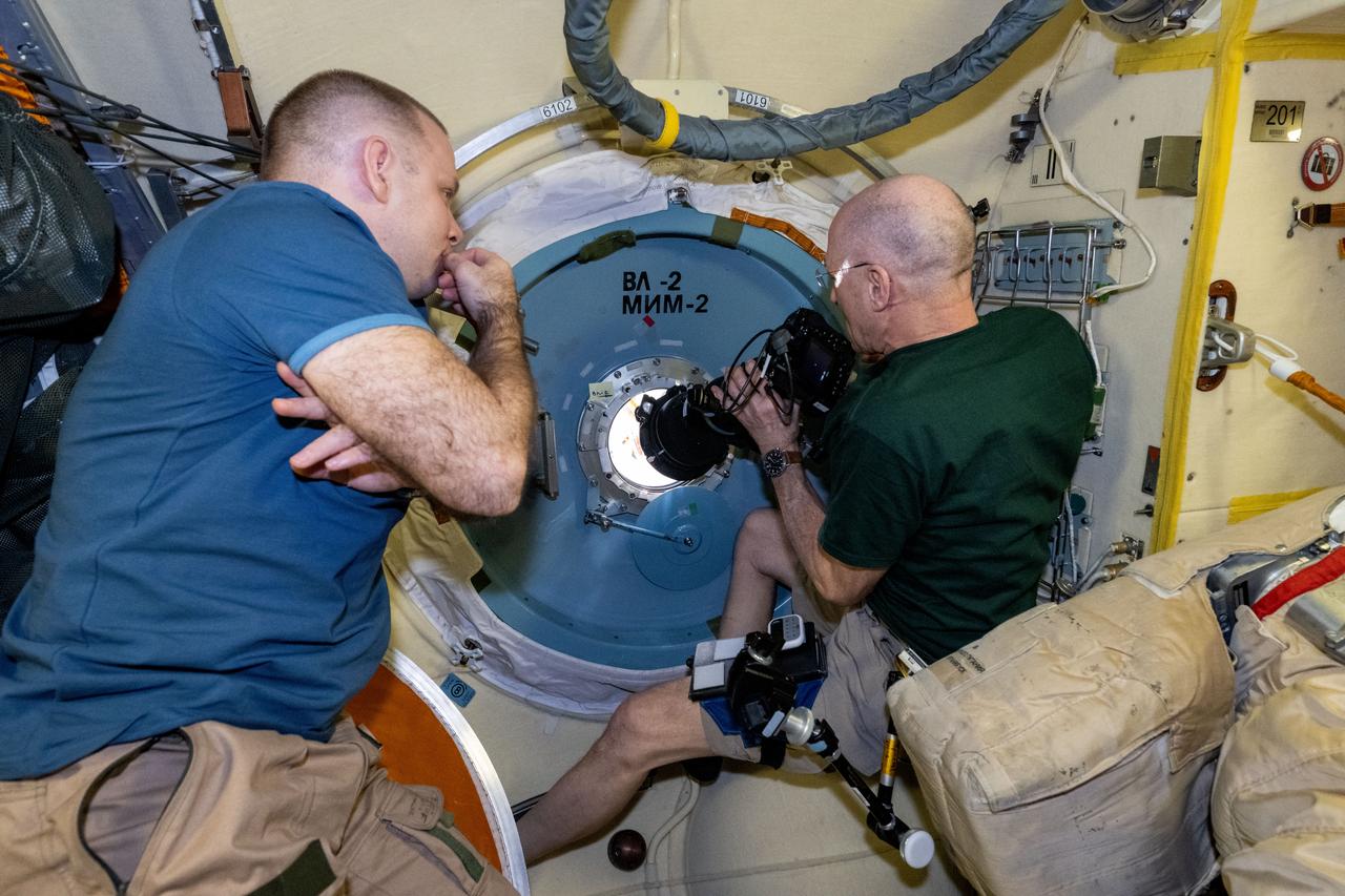
iss054e001441 (Dec. 19, 2017) --- Newly arrived Flight Engineers Scott Tingle and Anton Shkaplerov float into the Zvezda Service Module during an International Space Station tour and safety briefing.
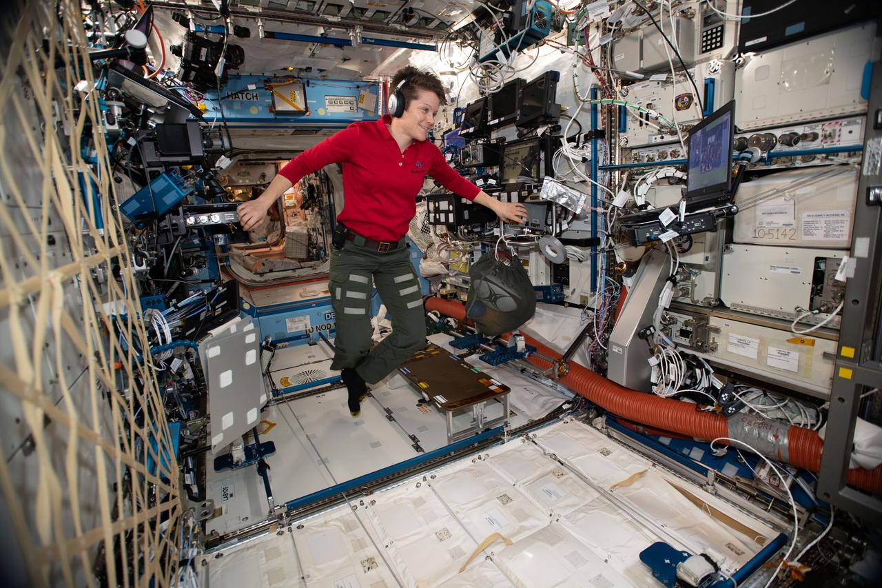
iss058e005069 (Jan. 18, 2019) --- Expedition 58 Flight Engineer Anne McClain of NASA looks at a laptop computer screen inside the U.S. Destiny laboratory module during ground conference operations.

The first RS-25 flight engine, engine No. 2059, is lifted onto the A-1 Test Stand at Stennis Space Center on Nov. 4, 2015. The engine was tested in early 2016 to certify it for use on NASA’s new Space Launch System (SLS). The SLS core stage will be powered by four RS-25 engines, all tested at Stennis Space Center. NASA is developing the SLS to carry humans deeper into space than ever before, including on a journey to Mars.
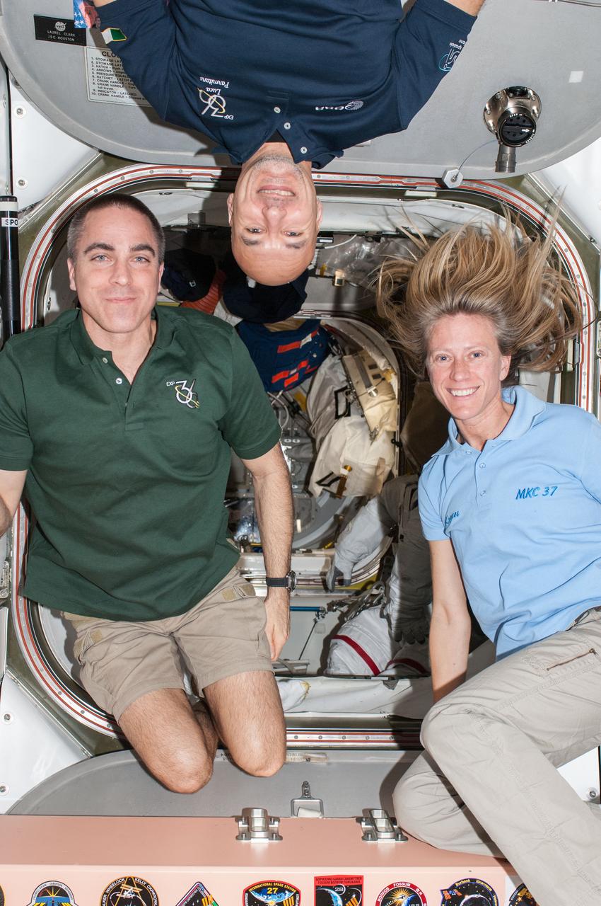
ISS036-E-013240 (29 June 2013) --- NASA astronauts Chris Cassidy (left) and Karen Nyberg; along with European Space Agency astronaut Luca Parmitano, all Expedition 36 flight engineers, pose for a photo at the hatchway between the Quest airlock and the Unity node of the International Space Station.
ISS036-E-013216 (29 June 2013) --- NASA astronauts Chris Cassidy (left) and Karen Nyberg; along with European Space Agency astronaut Luca Parmitano, all Expedition 36 flight engineers, pose for a photo at the hatchway between the Quest airlock and the Unity node of the International Space Station.
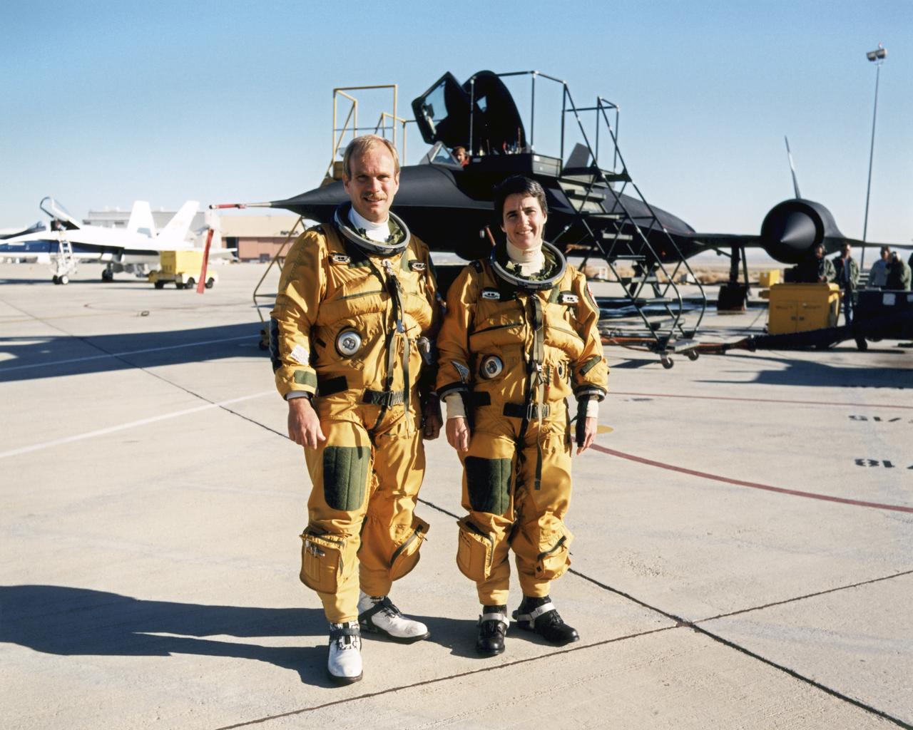
The husband-and-wife team of Bob Meyer and Marta Bohn-Meyer flew as flight test engineers on high-speed experiments flown on the triple-sonic SR-71 at NASA Dryden.
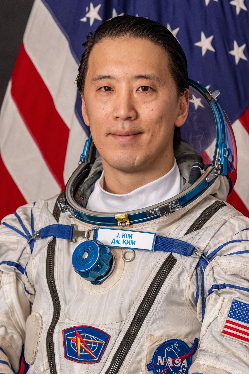
jsc2025e033524 (April 23, 2025) --- NASA astronaut and Soyuz MS-27 Flight Engineer Jonny Kim poses for a portrait in his Sokol launch and entry suit at the Gagarin Cosmonaut Training Center in Star City, Russia.

jsc2025e033528 (Feb. 10, 2025) --- Roscosmos cosmonaut and Soyuz MS-27 Flight Engineer Alexey Zubritsky poses for a portrait in his Sokol launch and entry suit at the Gagarin Cosmonaut Training Center in Star City, Russia.

jsc2025e033525 (Feb. 3, 2025) --- NASA astronaut and Soyuz MS-27 Flight Engineer Jonny Kim poses for a portrait in his Sokol launch and entry suit at the Gagarin Cosmonaut Training Center in Star City, Russia.

jsc2025e033530 (Feb. 10, 2025) --- NASA astronaut and Soyuz MS-27 Backup Flight Engineer Chris Williams poses for a portrait in his Sokol launch and entry suit at the Gagarin Cosmonaut Training Center in Star City, Russia.

jsc2025e033532 (Feb. 10, 2025) --- Roscosmos cosmonaut and Soyuz MS-27 Backup Flight Engineer Sergey Mikaev poses for a portrait in his Sokol launch and entry suit at the Gagarin Cosmonaut Training Center in Star City, Russia.
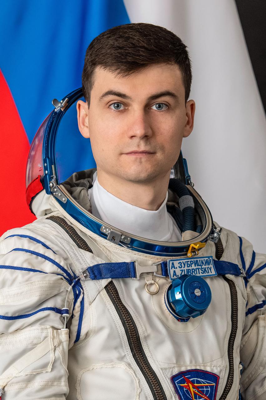
jsc2025e033527 (April 23, 2025) --- Roscosmos cosmonaut and Soyuz MS-27 Flight Engineer Alexey Zubritsky poses for a portrait in his Sokol launch and entry suit at the Gagarin Cosmonaut Training Center in Star City, Russia.
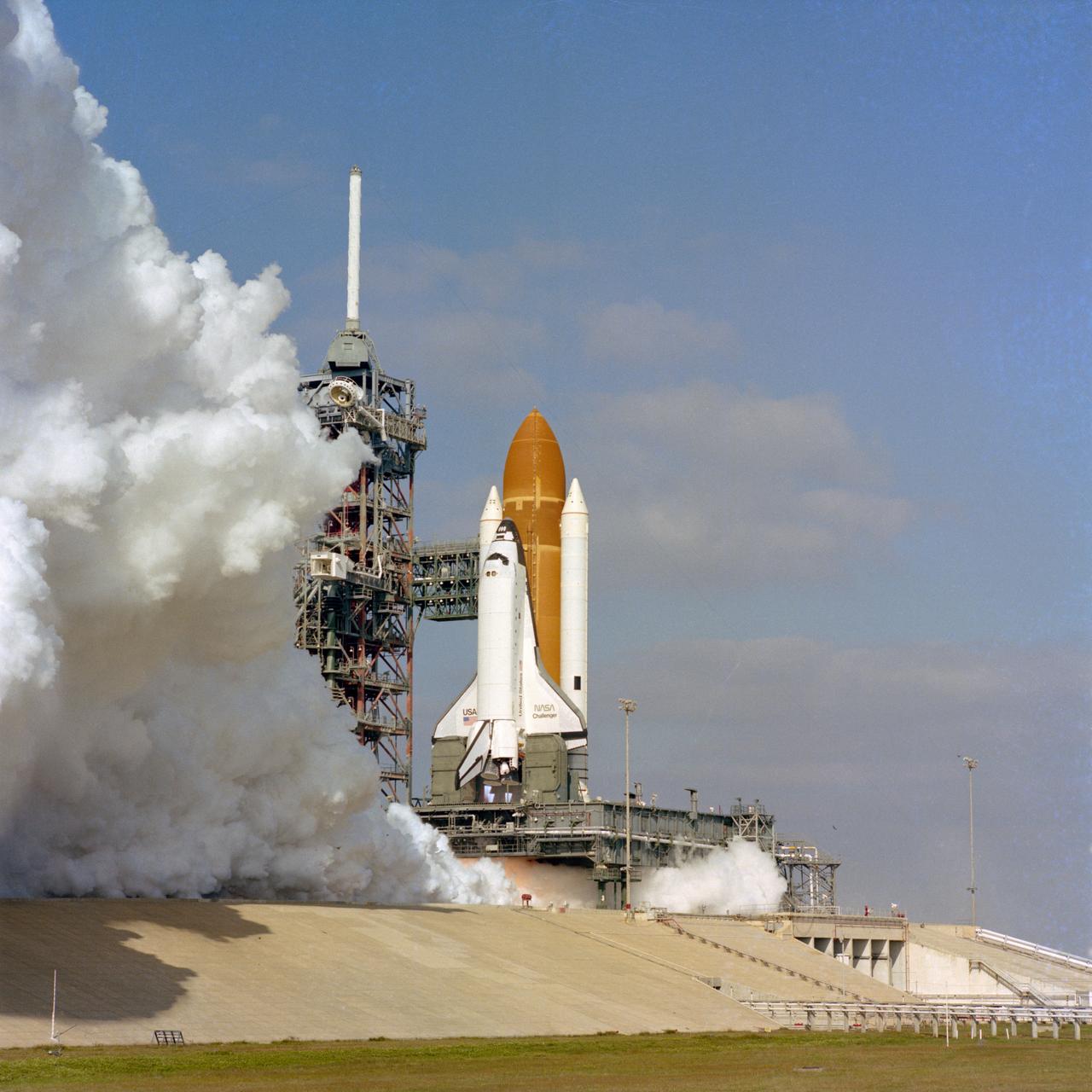
The Space shuttle orbiter Challenger is given a 20-second test firing of its new main engines on December 18, 1982 on pad 39A at the Kennedy Space Center. This test was the first time these engines ahd been tested in the clustered flight configuration.
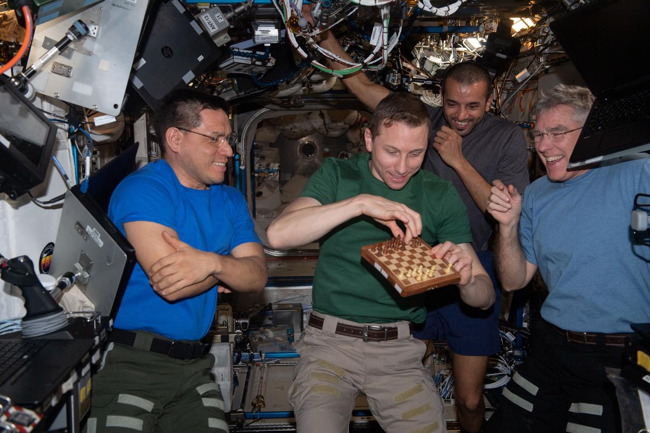
iss069e003900 (April 17, 2023) --- NASA astronaut and Expedition 69 Flight Engineer Woody Hoburg (center) makes a move during a space-to-ground chess tournament with mission controllers at NASA's Johnson Space Center in Houston, Texas. Watching Hoburg are (from left) fellow flight engineers Frank Rubio of NASA, Sultan Alneyadi of UAE (United Arab Emirates), and Stephen Bowen of NASA. Hoburg is a chess fan and set up a chess tournament with mission controllers with each side having their own chess board and typically making one or two moves a day during their busy schedules.
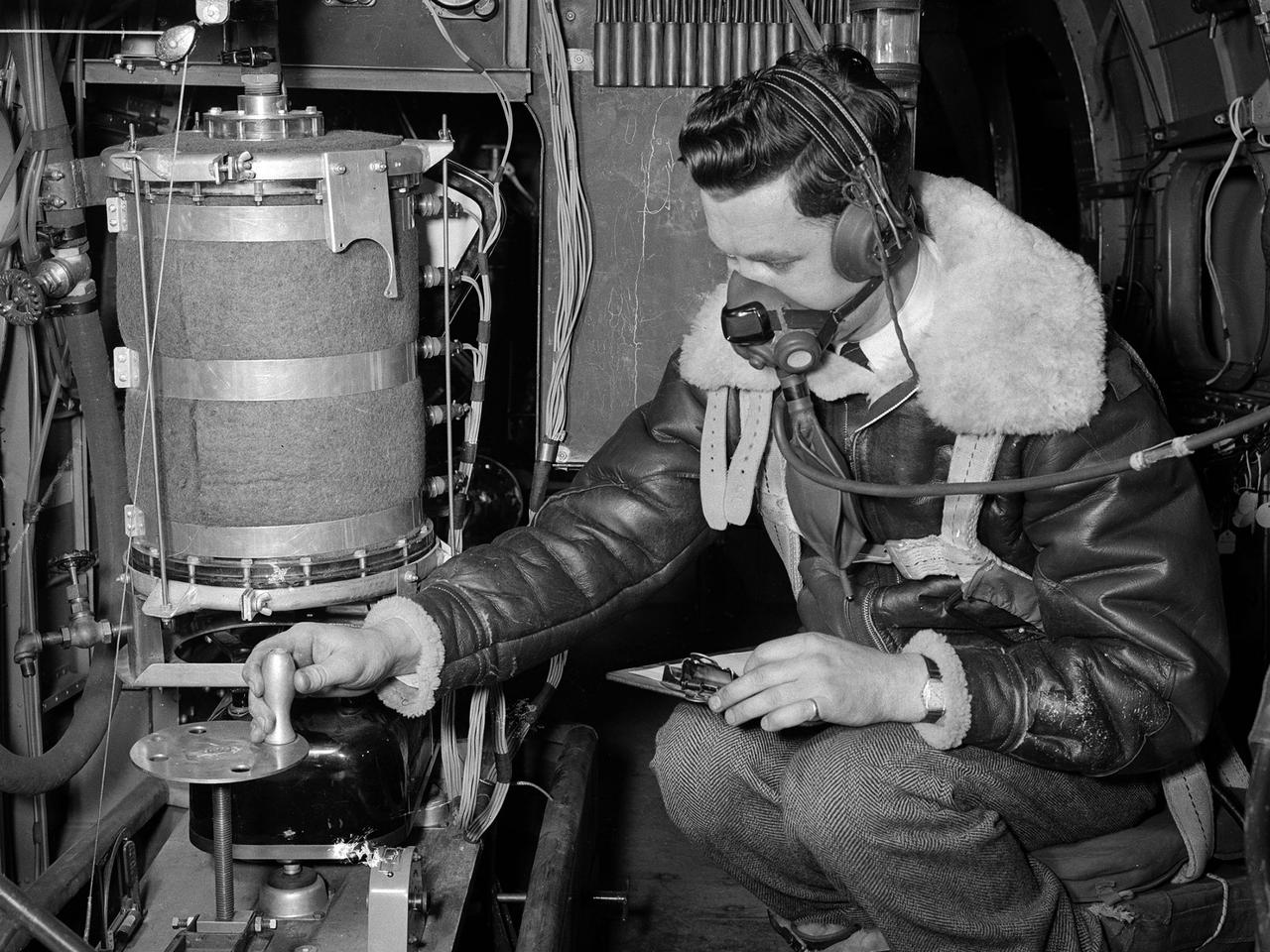
A flight engineer at the National Advisory Committee for Aeronautics (NACA) Aircraft Engine Research Laboratory monitors test equipment in the rear of the Lockheed RA–29 Hudson. Lockheed manufactured several variations of the light bomber in the late 1930s. The Hudson was one of the few military aircraft models available in large quantities during the early years of World War II, and both the US and British air forces utilized it as a patrol aircraft. The RA–29s were soon superseded by newer aircraft, but continued to serve as crew trainers, light cargo carriers and staff transports. The NACA flight engineers in the Planning and Analysis Section were responsible for working with researchers to install and monitor the experimental equipment on the NACA’s research aircraft. This process could require weeks or months. When larger aircraft, like the RA–29 Hudson, were utilized the flight engineers often participated in the flights. The NACA acquired their RA–29 in November 1943, and used the aircraft for fuel blend studies and instrumentation development. The Hudson also frequently served as a transportation vehicle for the staff and visitors. The RA–29 was transferred from the NACA in July 1945.
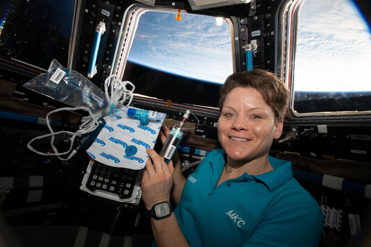
iss058e010750 (Feb. 6, 2019) --- Expedition 58 Flight Engineer Anne McClain of NASA is pictured in the cupola holding biomedical gear for the Marrow experiment. The study measures fat changes in the bone marrow before, and after exposure to microgravity. In addition, this investigation measures specific changes of red and white blood cell functions. Bone marrow fat is measured using magnetic resonance. Red blood cell function is measured with a breath sample analyzed with a gas chromatograph, and white blood cell function is studied through their genetic expression.

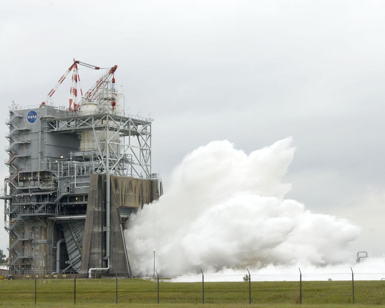
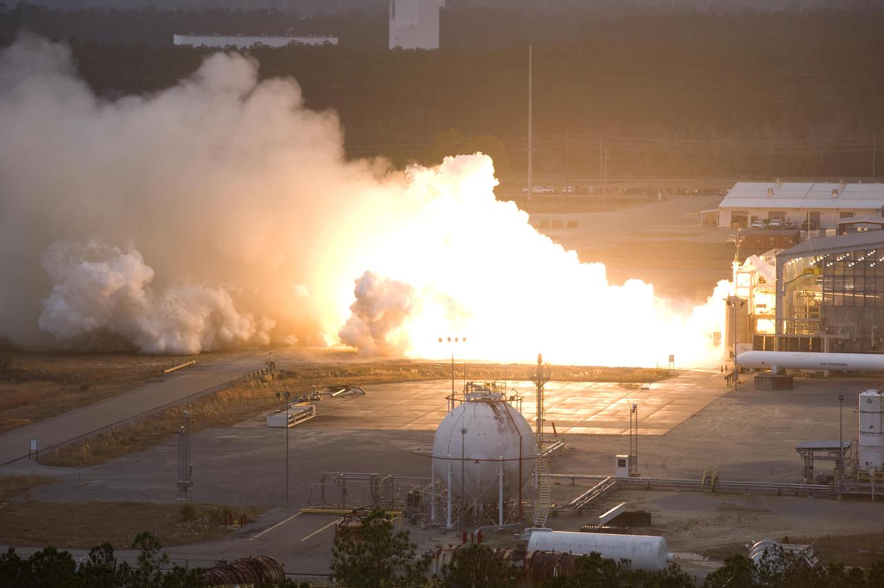
Steam blasts out of the A-2 Test Stand at Stennis Space Center on Oct. 22 as engineers begin a certification test on engine 2061, the last space shuttle main flight engine scheduled to be built. Since 1975, Stennis has tested every space shuttle main engine used in the program - about 50 engines in all. Those engines have powered more than 120 shuttle missions - and no mission has failed as a result of engine malfunction. For the remainder of 2008 and throughout 2009, Stennis will continue testing of various space shuttle main engine components.
Steam blasts out of the A-2 Test Stand at Stennis Space Center on Oct. 22 as engineers begin a certification test on engine 2061, the last space shuttle main flight engine scheduled to be built. Since 1975, Stennis has tested every space shuttle main engine used in the program - about 50 engines in all. Those engines have powered more than 120 shuttle missions - and no mission has failed as a result of engine malfunction. For the remainder of 2008 and throughout 2009, Stennis will continue testing of various space shuttle main engine components.

jsc2024e066721 (Oct. 4, 2024) --- NASA astronaut Nichole Ayers, SpaceX Crew-10 Pilot and Expedition 73 Flight Engineer, poses for a crew portrait at Johnson Space Center in Houston, Texas.
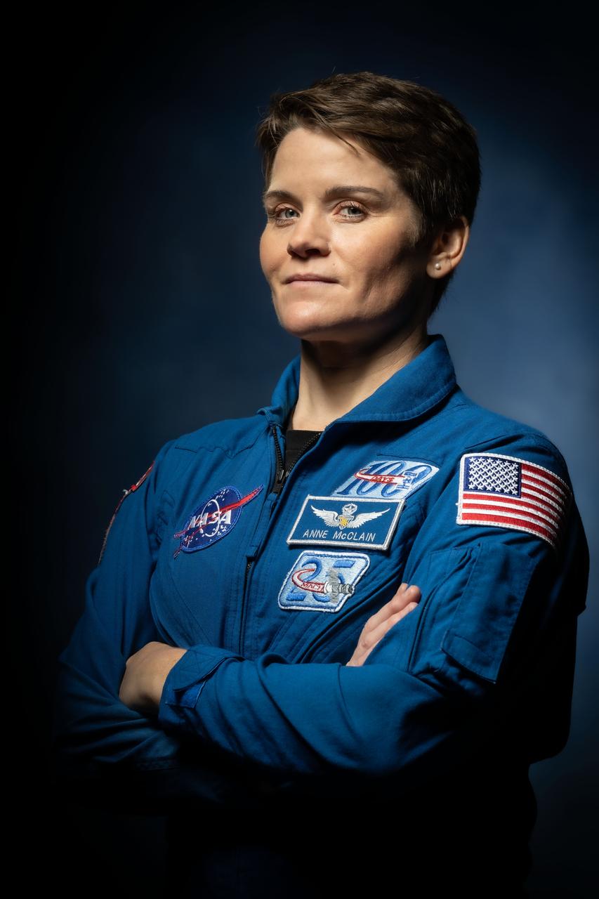
jsc2024e066730_alt (Oct. 4, 2024) --- NASA astronaut Anne McClain, SpaceX Crew-10 Commander and Expedition 73 Flight Engineer, poses for a crew portrait at Johnson Space Center in Houston, Texas.
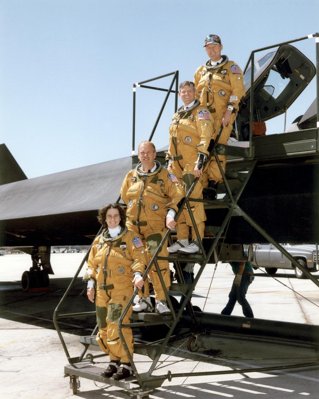
Flight engineers Marta Bohn-Meyer and Bob Meyer and pilots Ed Schneider and Rogers Smith flew the triple-sonic SR-71 in high-speed research experiments at NASA Dryden.
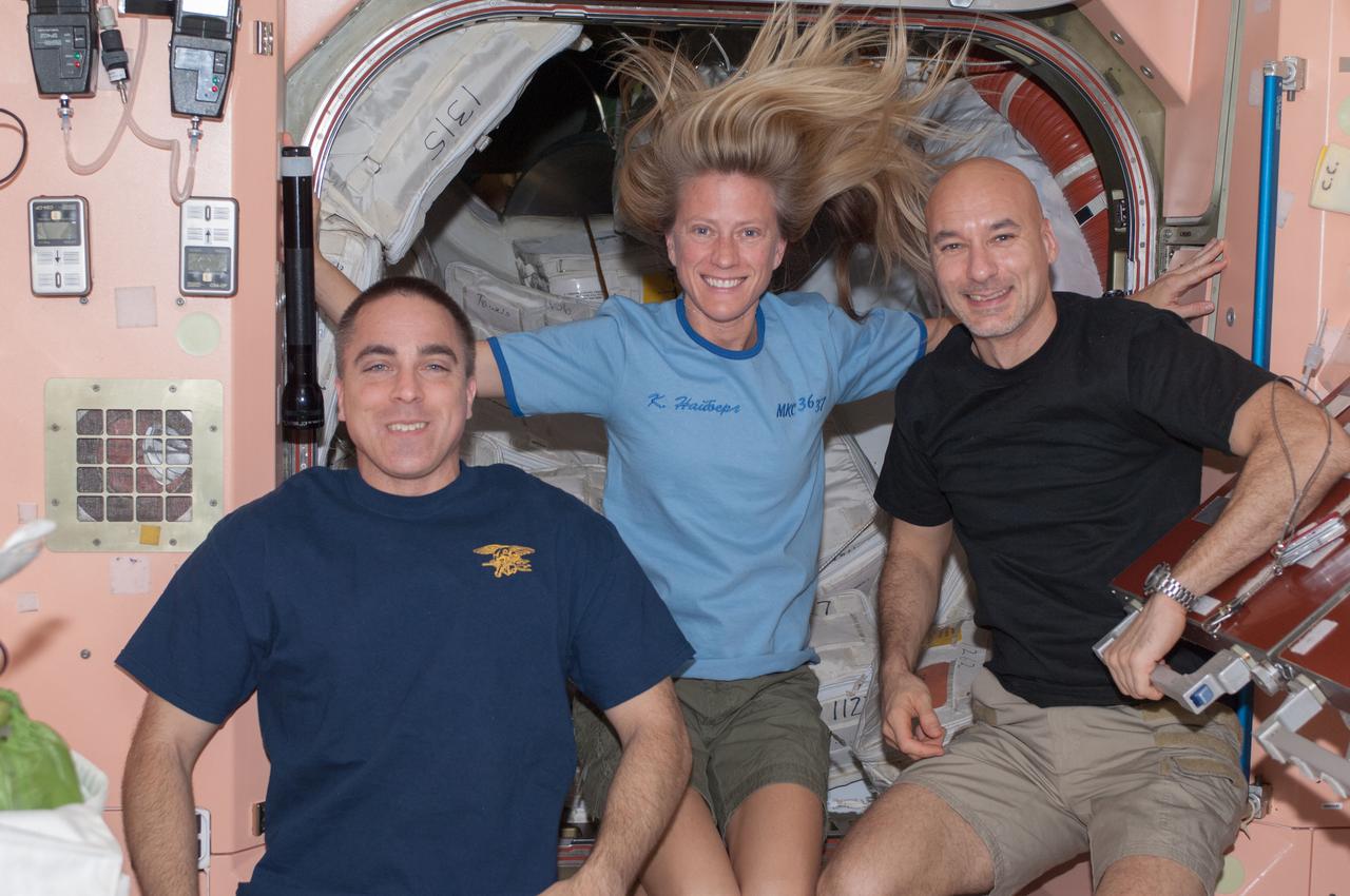
View of Astronauts Chris Cassidy (left),Karen Nyberg (center) and European Space Agency astronaut Luca Parmitano,all Expedition 36 flight engineers,in the Node 1 module.
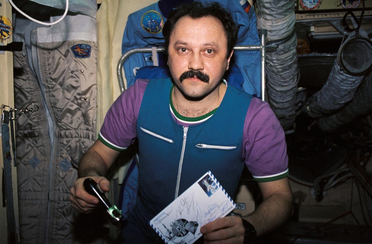
NM21-397-034 (For Release October 1996) --- Cosmonaut Yury V. Usachev, Mir 21 flight engineer, holds a peeler and a piece of mail received along with the food in the Base Block module of the Mir Space Station.
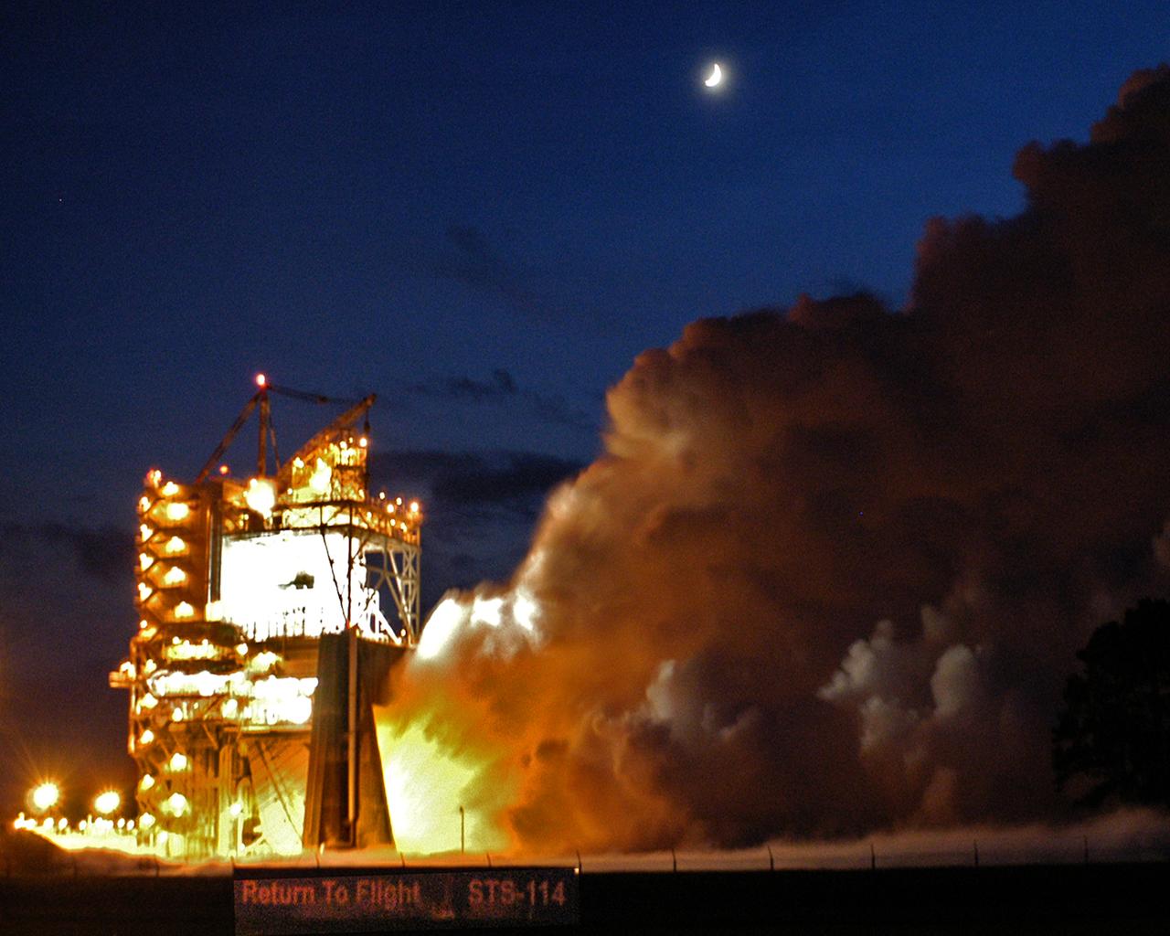
The Space Shuttle's Main Engine (SSME) reached another milestone Aug. 19, 2004, when a successful flight acceptance test was conducted at NASA Stennis Space Center (SSC). The engine tested was the final of three engines that will carry the next Space Shuttle into orbit. The engine will be shipped to NASA Kennedy Space Center in Florida for installation on Space Shuttle Discovery for STS-114, NASA's Return to Flight mission. The engine test, which began about 8:10 p.m. CDT, ran for 520 seconds (8 minutes), the length of time it takes for the Space Shuttle to reach orbit.
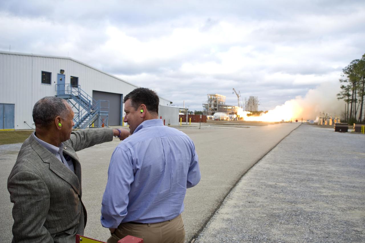
NASA Administrator Charles Bolden (l) and John C. Stennis Space Center Director Patrick Scheuermann watch the successful test of the first Aerojet AJ26 flight engine Feb. 7, 2011. The test was conducted on the E-1 Test Stand at Stennis. The engine now will be sent to Wallops Flight Facility in Virginia, where it will be used to power the first stage of Orbital Sciences Corporation's Taurus II space vehicle. The Feb. 7 test supports NASA's commitment to partner with companies to provide commercial cargo flights to the International Space Station. NASA has partnered with Orbital to carry out the first of eight cargo missions to the space station in early 2012.
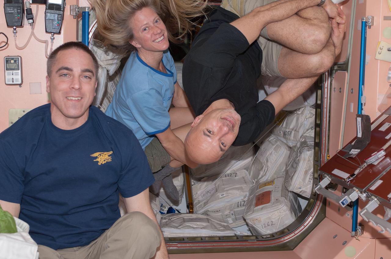
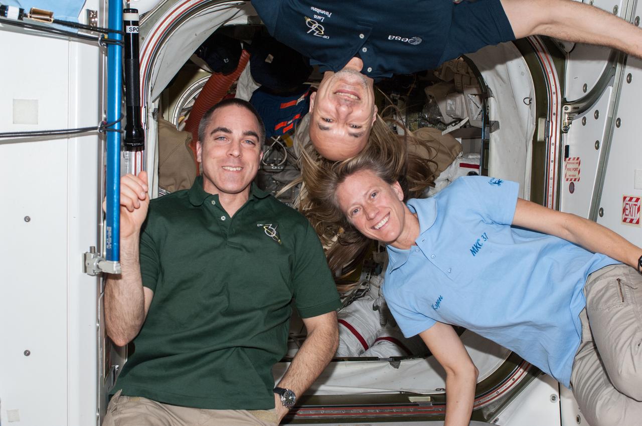
ISS036-E-015477 (7 July 2013) --- NASA astronauts Chris Cassidy (left) and Karen Nyberg; along with European Space Agency astronaut Luca Parmitano, all Expedition 36 flight engineers, pose for a photo in the Unity node of the International Space Station.
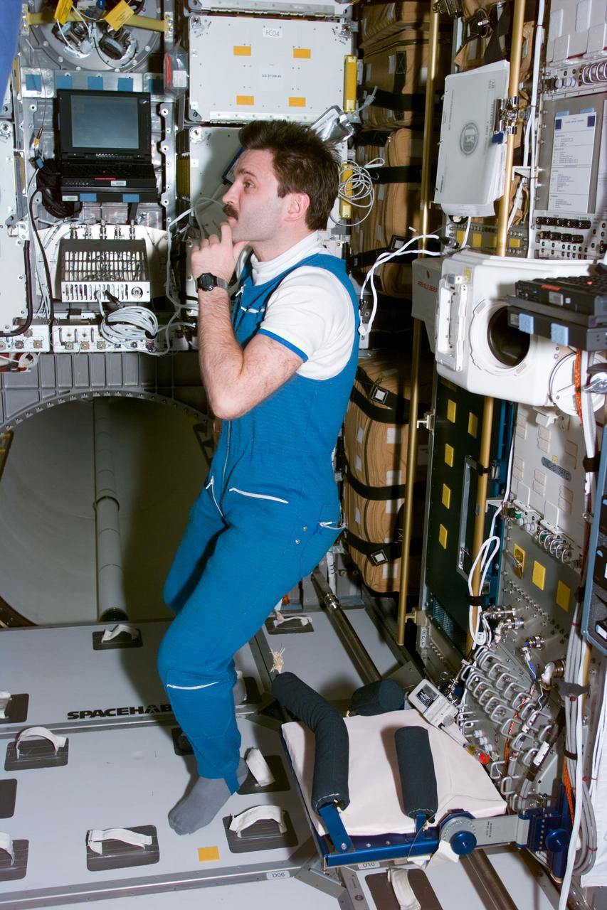
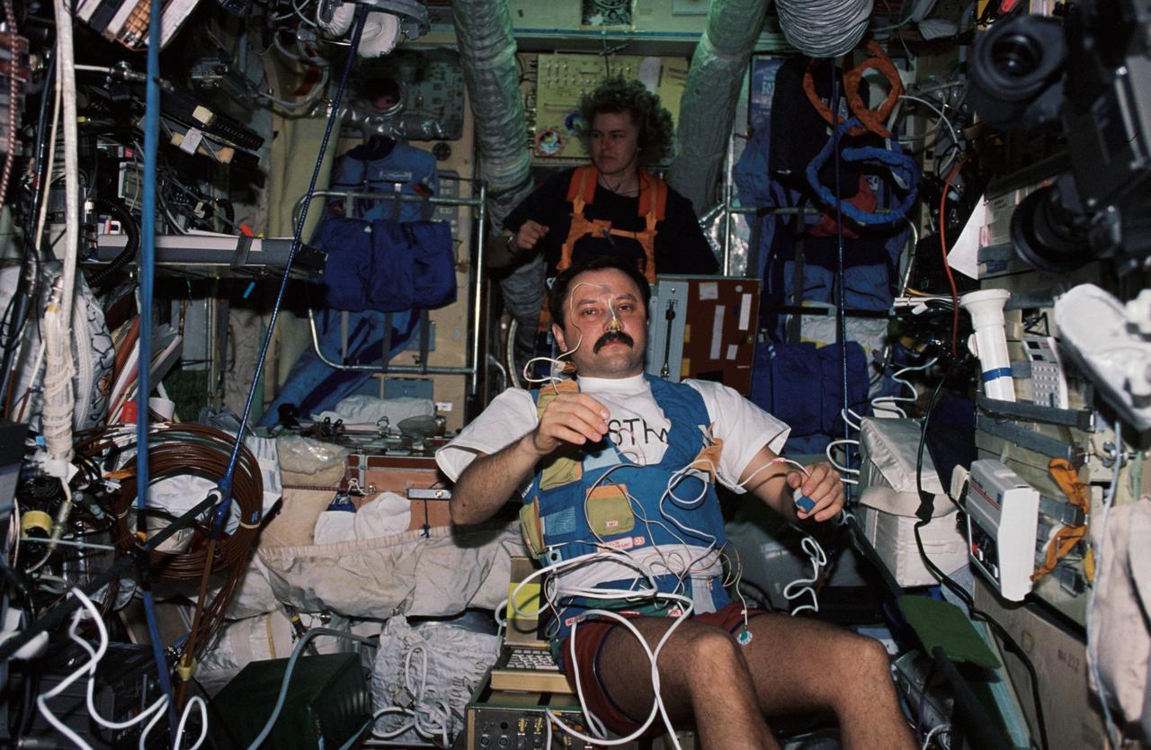
STS081-E-05482 (16 Jan. 1997) --- Perhaps overwhelmed by a giant stock of supplies (out of frame, left), cosmonaut Aleksandr Y. Kaleri, Mir-22 flight engineer, ponders what parcel to transfer next from the Spacehab Double Module (DM) to the Russian Mir Space Station complex. The photograph was recorded with an Electronic Still Camera (ESC) and later was downlinked to flight controllers in Houston, Texas.
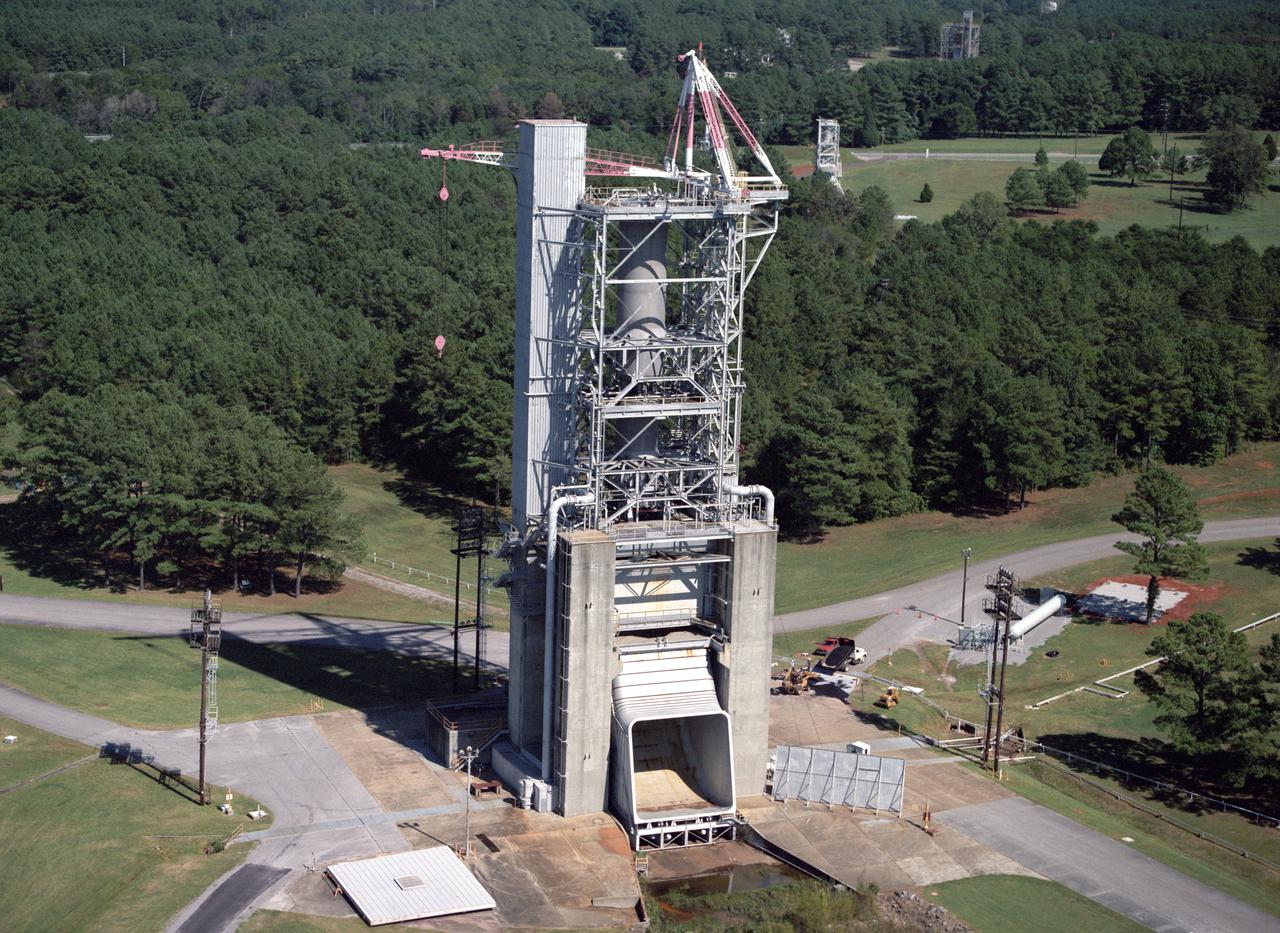
Marshall Space Flight Center's F-1 Engine Test Stand is shown in this picture. Constructed in 1963, the test stand is a vertical engine firing test stand, 239 feet in elevation and 4,600 square feet in area at the base, and was designed to assist in the development of the F-1 Engine. Capability is provided for static firing of 1.5 million pounds of thrust using liquid oxygen and kerosene. The foundation of the stand is keyed into the bedrock approximately 40 feet below grade.
iss072e350829 (Dec. 7, 2024) --- NASA astronaut and Expedition 72 Flight Engineer Don Pettit points a camera outside a window on the International Space Station's Poisk module for a sun photography session with assistance from Roscosmos cosmonaut and Expedition 72 Flight Engineer Ivan Vagner.
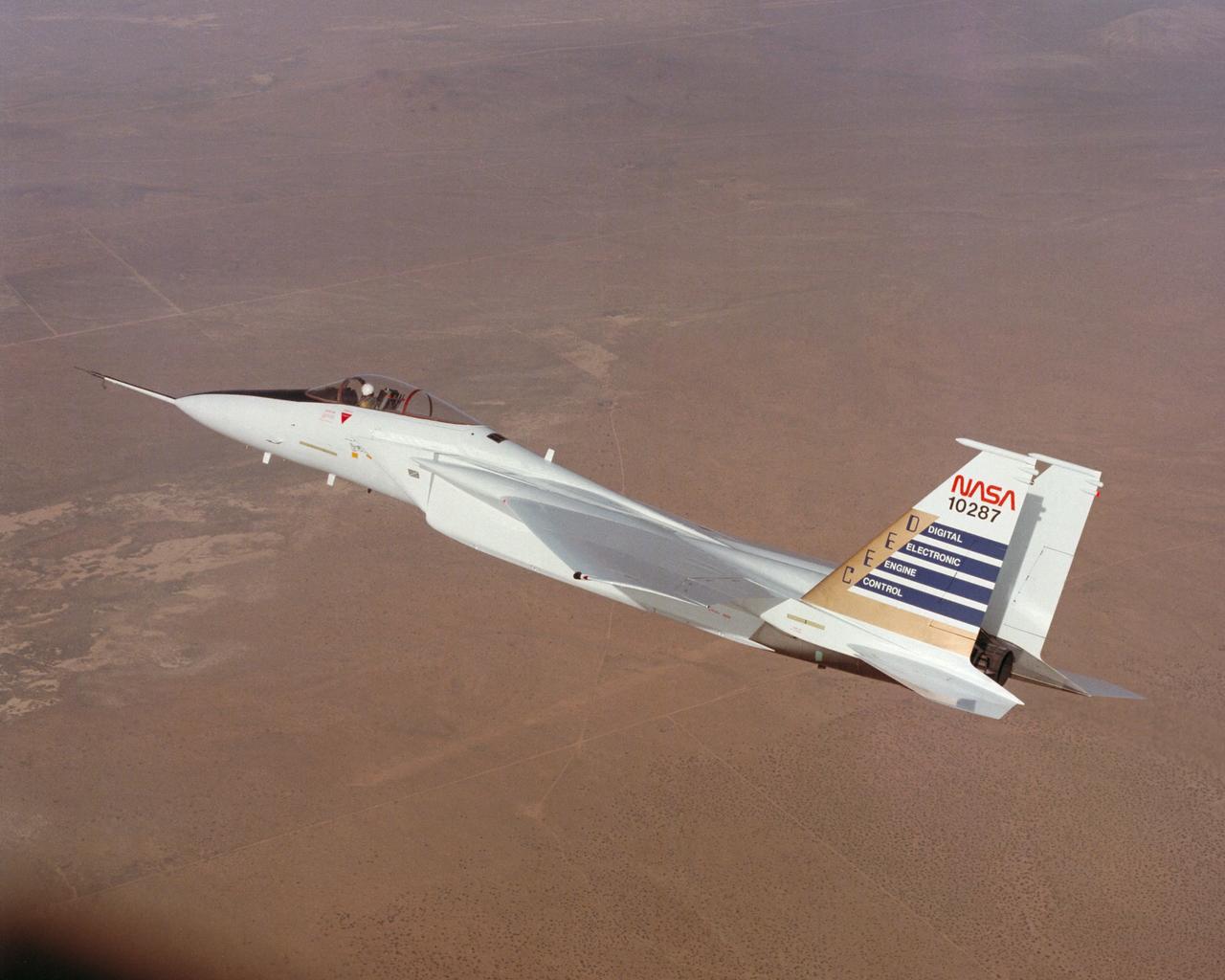
Digital Electronic Engine Control F-15A #287 in flight.

jsc2024e066718 (Oct. 4, 2024) --- Roscosmos cosmonaut Kirill Peskov, SpaceX Crew-10 Mission Specialist and Expedition 73 Flight Engineer, poses for a crew portrait at Johnson Space Center in Houston, Texas.
John C. Stennis Space Center engineers conduct a 55-second test fire of Aerojet's liquid-fuel AJ26 rocket engine that will power the first stage of Orbital Sciences Corporation's Taurus II space launch vehicle. The Dec. 17, 2010 test was conducted on the E-1 Test Stand at Stennis in support of NASA's Commercial Transportation Services partnerships to enable commercial cargo flights to the International Space Station. Orbital is under contract with NASA to provide eight cargo missions to the space station through 2015.

John C. Stennis Space Center engineers conduct a 55-second test fire of Aerojet's liquid-fuel AJ26 rocket engine that will power the first stage of Orbital Sciences Corporation's Taurus II space launch vehicle. The Dec. 17, 2010 test was conducted on the E-1 Test Stand at Stennis in support of NASA's Commercial Transportation Services partnerships to enable commercial cargo flights to the International Space Station. Orbital is under contract with NASA to provide eight cargo missions to the space station through 2015.
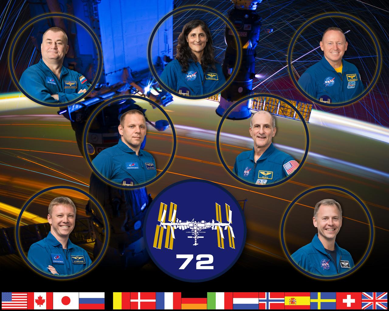
iss072-s-002 (Oct. 27, 2023) --- The official portrait of the International Space Station's Expedition 72 crew. At the top (from left) are, Roscosmos cosmonaut and Flight Engineer Alexey Ovchinin, NASA astronaut and space station Commander Suni Williams, and NASA astronaut and Flight Engineer Butch Wilmore. In the middle row are, Roscosmos cosmonaut and Flight Engineer Ivan Vagner and NASA astronaut and Flight Engineer Don Pettit. In the bottom row are, Roscosmos cosmonaut and Flight Engineer Aleksandr Gorbunov and NASA astronaut and Flight Engineer Nick Hague. Credit: NASA/Bill Stafford and Robert Markowitz

JSC2005-E-13483 (March 2005) --- Roberto Vittori, European Space Agency, Soyuz flight engineer, TMA-6.

An artist's rendering of the air-breathing, hypersonic X-43B, the third and largest of NASA's Hyper-X series flight demonstrators, which could fly later this decade. Revolutionizing the way we gain access to space is NASA's primary goal for the Hypersonic Investment Area, managed for NASA by the Advanced Space Transportation Program at the Marshall Space Flight Center in Huntsville, Alabama. The Hypersonic Investment area, which includes leading-edge partners in industry and academia, will support future generation reusable vehicles and improved access to space. These technology demonstrators, intended for flight testing by decade's end, are expected to yield a new generation of vehicles that routinely fly about 100,000 feet above Earth's surface and reach sustained speeds in excess of Mach 5 (3,750 mph), the point at which "supersonic" flight becomes "hypersonic" flight. The flight demonstrators, the Hyper-X series, will be powered by air-breathing rocket or turbine-based engines, and ram/scramjets. Air-breathing engines, known as combined-cycle systems, achieve their efficiency gains over rocket systems by getting their oxygen for combustion from the atmosphere, as opposed to a rocket that must carry its oxygen. Once a hypersonic vehicle has accelerated to more than twice the speed of sound, the turbine or rockets are turned off, and the engine relies solely on oxygen in the atmosphere to burn fuel. When the vehicle has accelerated to more than 10 to 15 times the speed of sound, the engine converts to a conventional rocket-powered system to propel the craft into orbit or sustain it to suborbital flight speed. NASA's series of hypersonic flight demonstrators includes three air-breathing vehicles: the X-43A, X-43B and X-43C.
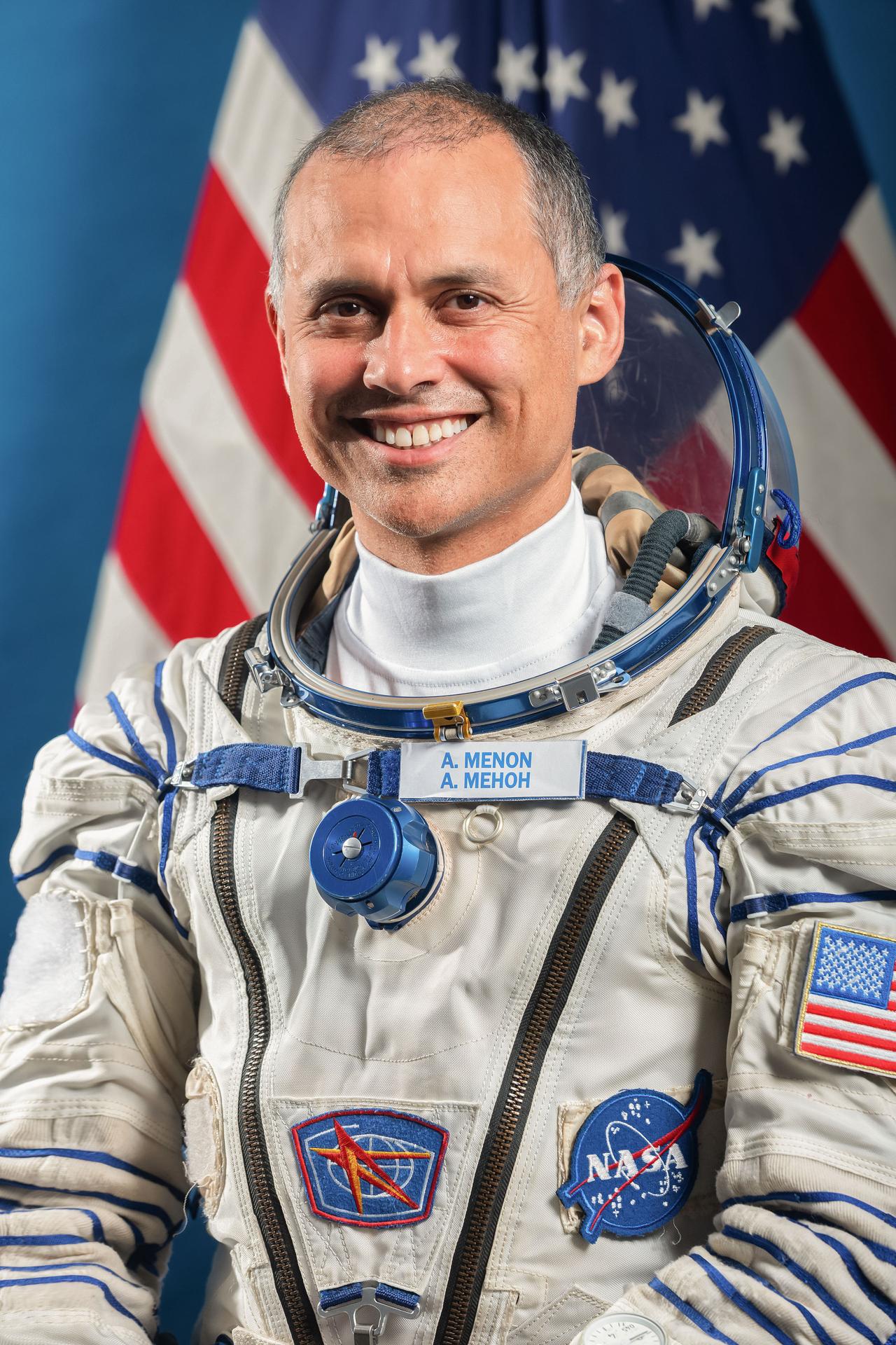
jsc2025e074501 (June 9, 2025) --- NASA astronaut and Soyuz MS-28 Backup Flight Engineer Anil Menon poses for a portrait in his Sokol launch and entry suit at the Gagarin Cosmonaut Training Center in Star City, Russia. Credit: GCTC

jsc2025e074503 (July 2, 2025) --- Roscosmos cosmonaut and Soyuz MS-28 Backup Flight Engineer Anna Kikina poses for a portrait in her Sokol launch and entry suit at the Gagarin Cosmonaut Training Center in Star City, Russia. Credit: GCTC
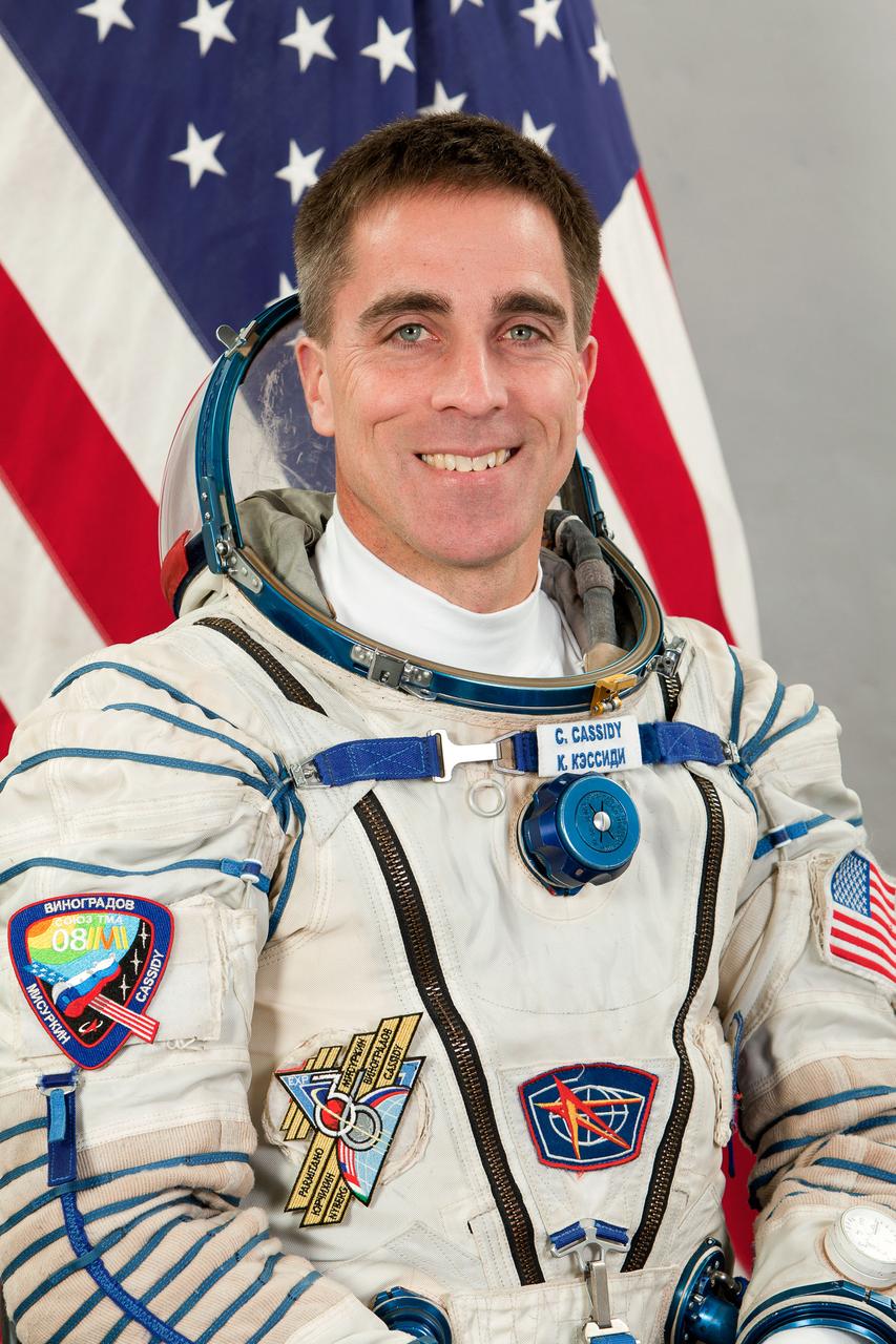
JSC2013-E-013362 (February 2013) --- Portrait of Expedition 35/36 Flight Engineer Chris Cassidy of NASA. Photo credit: Gagarin Cosmonaut Training Center
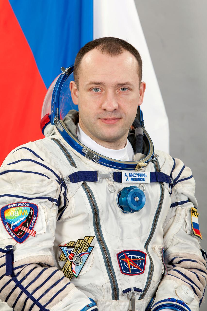
JSC2013-E-013364 (February 2013) --- Portrait of Expedition 35/36 Flight Engineer Alexander Misurkin of Roscosmos. Photo credit: Gagarin Cosmonaut Training Center
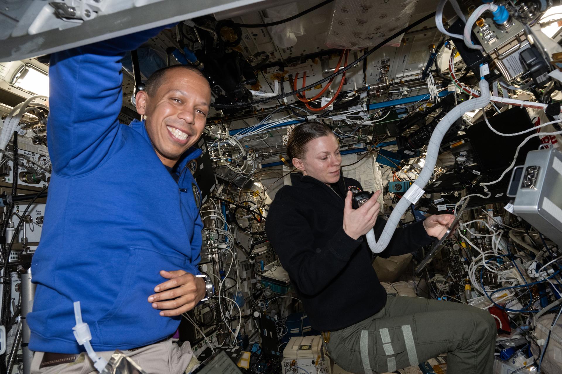
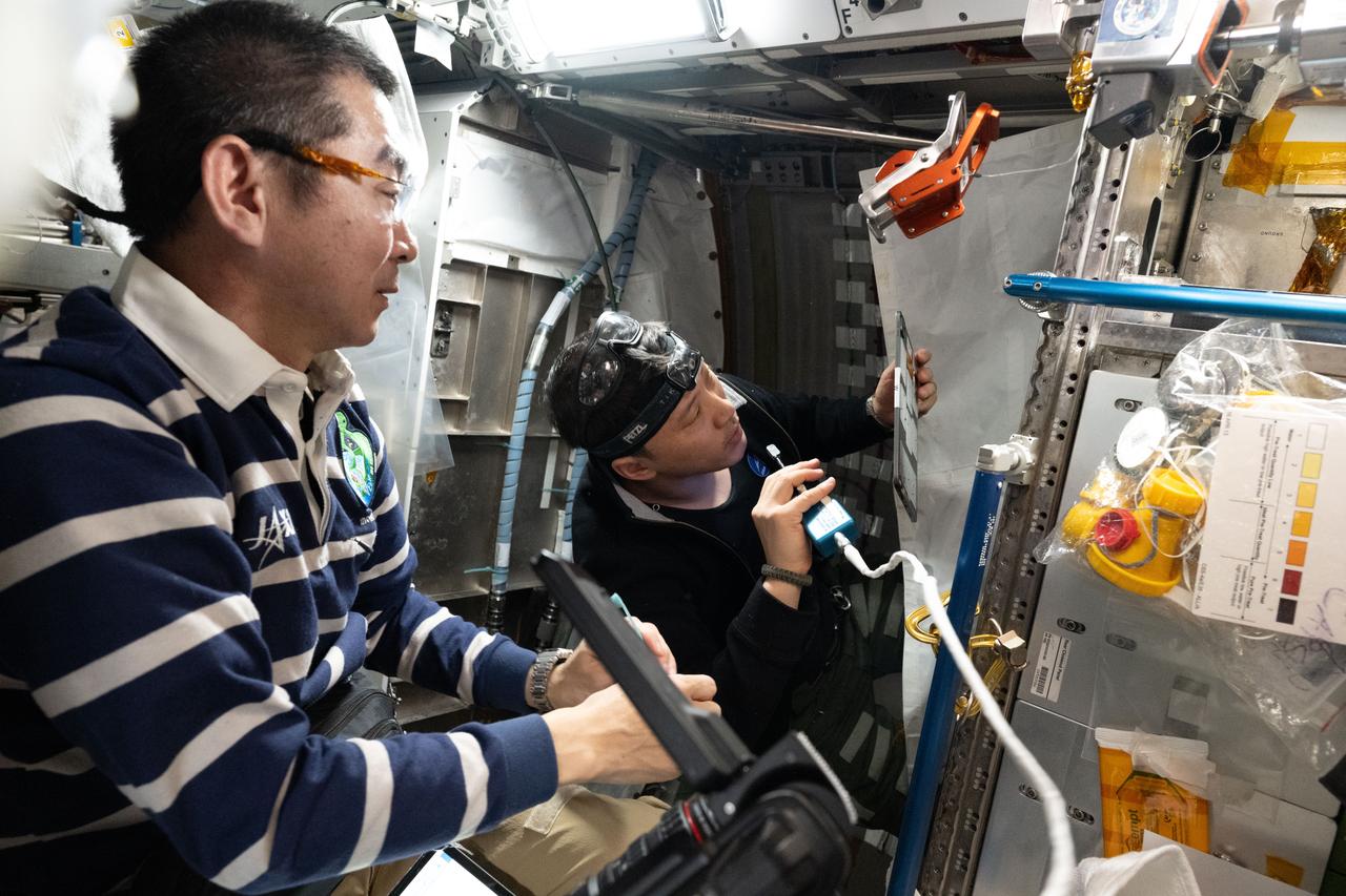
iss073e1198126 (Nov. 28, 2025) --- Expedition 73 Flight Engineers Chris Williams and Zena Cardman, both NASA astronauts, seen here with the ISS Ham Radio during a school contact inside the International Space Station's Columbus laboratory module. Cardman was helping new NASA Flight Engineer Chris Williams familiarize himself with station hardware, operations, and systems during his second day aboard the orbital outpost.
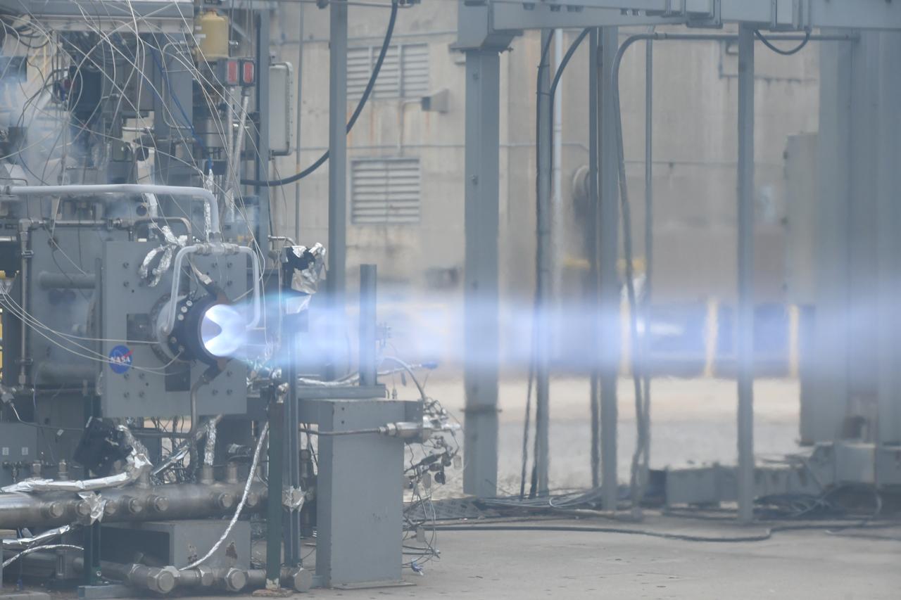
Engineers at NASA’s Marshall Space Flight Center in Huntsville, Alabama, conduct a successful, 251-second hot fire test of a full-scale Rotating Detonation Rocket Engine combustor in fall 2023, achieving more than 5,800 pounds of thrust.

Student Assistant Antoinette Davis (left) of Utica; Carmella Forsythe, 13, of Clinton; Terri Henderson, 14, of Clinton; Tyra Greer, 12, of Port Gibson; and Kala Battle, 14, of Edwards, answer curriculum questions about NASA's Return to Flight mission exhibit at StenniSphere, the visitor center at NASA's Stennis Space Center (SSC) near Bay St. Louis, Miss. The girls were on a field trip to StenniSphere with fellow participants in Hinds Community College's MSEIP (Minority Science Engineering Improvement Program) summer program. MSEIP encourages students to pursue and prepare for careers in science, technology, engineering and math.

ISS005-E-06010 (June 2002) --- Cosmonaut Sergei Y. Treschev, Expedition Five flight engineer representing Rosaviakosmos, works in the Zvezda Service Module on the International Space Station (ISS).
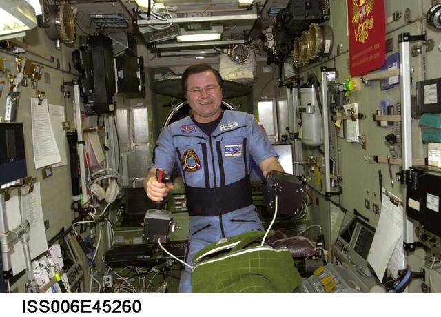
ISS006-E-45260 (20 March 2003) --- Cosmonaut Nikolai M. Budarin, Expedition Six flight engineer, is pictured in the Zvezda Service Module on the International Space Station (ISS). Budarin represents Rosaviakosmos.
NM21-388-012 (For Release October 1996) --- Astronaut Shannon Lucid (background) exercises on the treadmill in the Mir space station Base Block while Mir 21 flight engineer Yury V. Usachev is wired for an experiment.
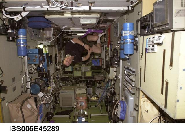
ISS006-E-45289 (21 March 2003) --- Cosmonaut Nikolai M. Budarin, Expedition Six flight engineer, floats in the Zvezda Service Module on the International Space Station (ISS). Budarin represents Rosaviakosmos.
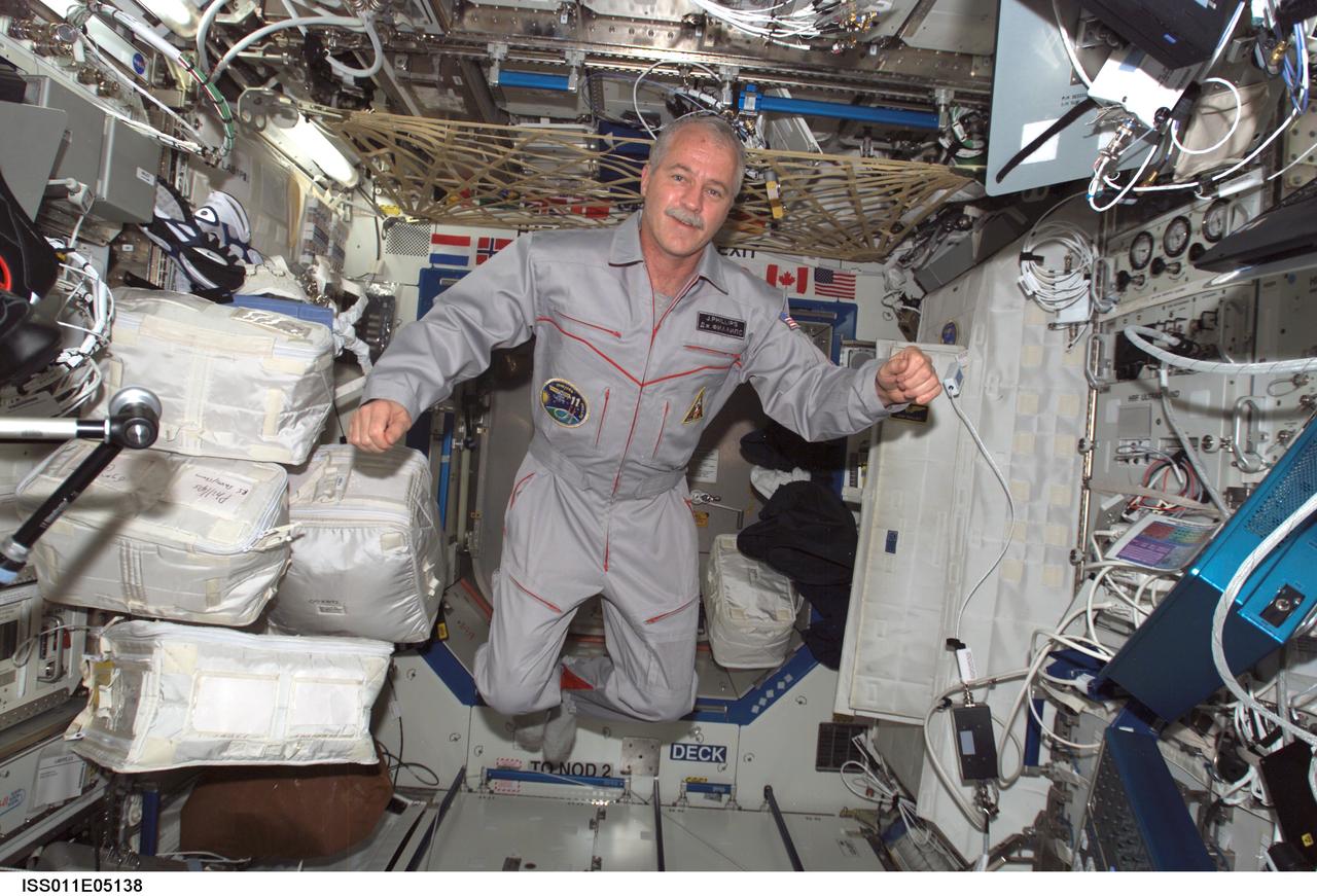
ISS011-E-05138 (17 April 2005) --- Astronaut John L. Phillips, Expedition 11 NASA ISS science officer and flight engineer, floats in the Destiny laboratory of the International Space Station (ISS).
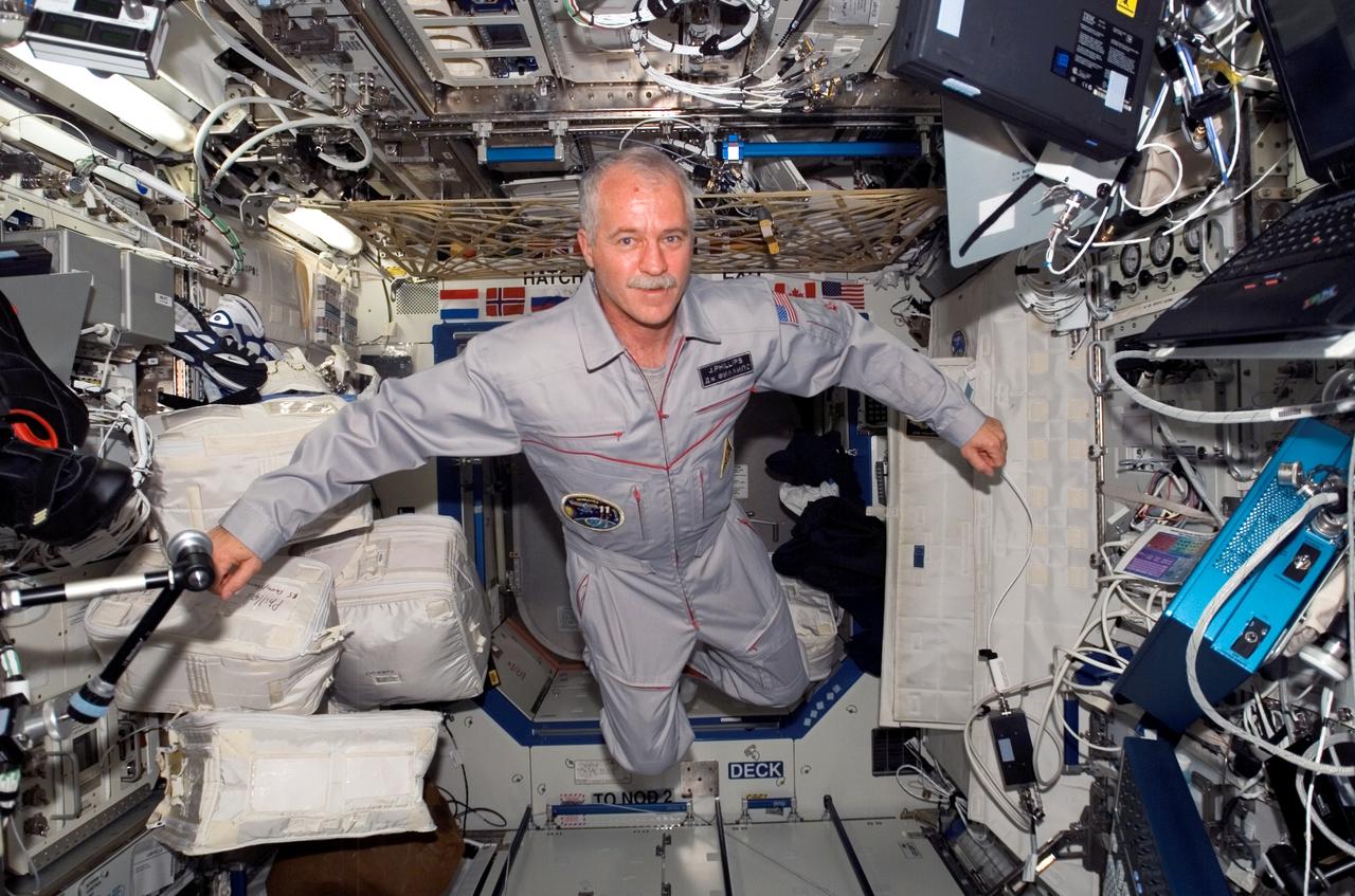
ISS011-E-05140 (17 April 2005) --- Astronaut John L. Phillips, Expedition 11 NASA science officer and flight engineer, floats in the Destiny laboratory of the international space station.
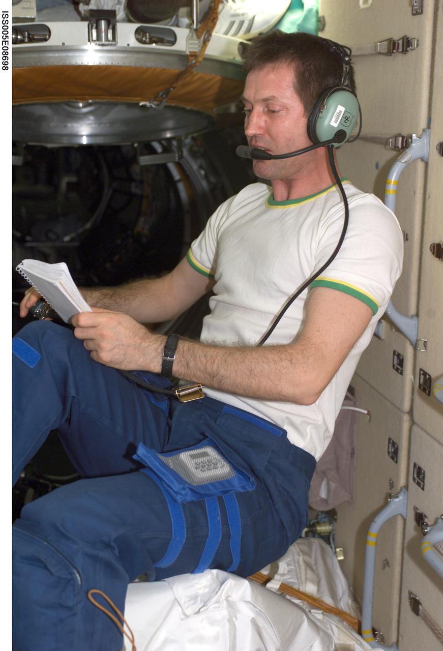
ISS005-E-08698 (6 August 2002) --- Cosmonaut Sergei Y. Treschev, Expedition Five flight engineer, uses an amateur radio in the functional cargo block (FGB) on the International Space Station (ISS). Treschev represents Rosaviakosmos.
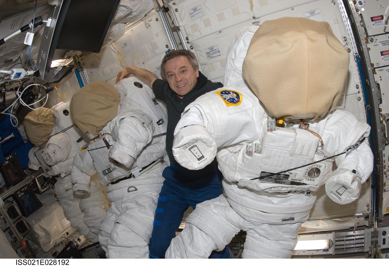
ISS021-E-028192 (17 Nov. 2009) --- Canadian Space Agency astronaut Robert Thirsk, Expedition 21 flight engineer, is pictured with three Extravehicular Mobility Unit (EMU) spacesuits in the Columbus laboratory of the International Space Station.
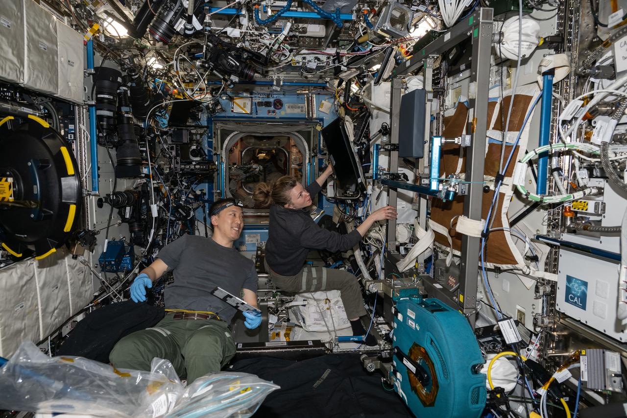
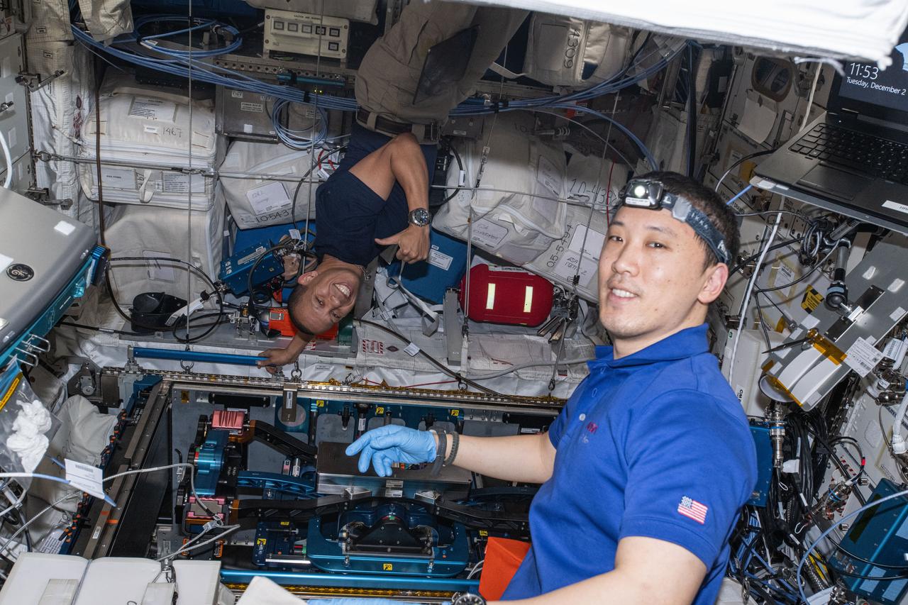
iss073e0546282 (Aug. 26, 2025) --- Expedition 73 Flight Engineers Jonny Kim and Zena Cardman, both NASA astronauts, work together inside the International Space Station's Destiny laboratory module on science maintenance activities.
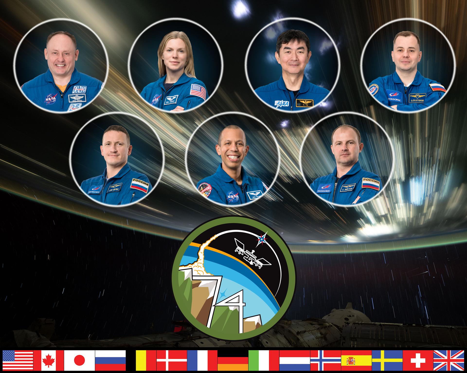
iss074-s-002 (Oct. 16, 2024) --- The official portrait of the Expedition 74 crew on the International Space Station. Top row from left, Commander Mike Fincke and Flight Engineer Zena Cardman, both NASA astronauts, JAXA (Japan Aerospace Exploration Agency) Flight Engineer Kimiya Yui, and Roscosmos Flight Engineer Oleg Platonov. Bottom row, Roscosmos Flight Engineer Sergey Kud-Sverchkov, NASA astronaut Chris Williams, and Roscosmos Flight Engineer Sergei Mikaev.
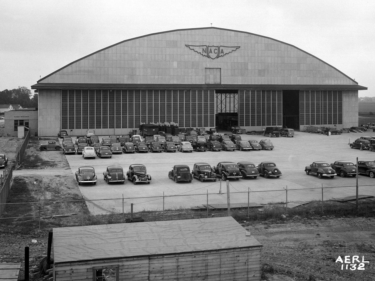
The Flight Research Building at the National Advisory Committee for Aeronautics (NACA) Aircraft Engine Research Laboratory is a 272- by 150-foot hangar with an internal height up to 90 feet. The hangar’s massive 37.5-foot-tall and 250-foot-long doors can be opened in sections to suit different size aircraft. The hangar has sheltered a diverse fleet of aircraft over the decades. These have ranged from World War II bombers to Cessna trainers and from supersonic fighter jets to a DC–9 airliner. At the time of this September 1942 photograph, however, the hangar was being used as an office building during the construction of the laboratory. In December of 1941, the Flight Research Building became the lab’s first functional building. Temporary offices were built inside the structure to house the staff while the other buildings were completed. The hangar offices were used for an entire year before being removed in early 1943. It was only then that the laboratory acquired its first aircraft, pilots and flight mechanics. The temporary one-story offices can be seen in this photograph inside the large sliding doors. Also note the vertical lift gate below the NACA logo. The gate was installed so that the tails of larger aircraft could pass into the hangar. The white Farm House that served as the Administration Building during construction can be seen in the distance to the left of the hangar.

Engineers at NASA‘s Armstrong Flight Research Center sit in a control room to monitor the remotely-piloted Ikhana aircraft during a test flight. The test flight was used to validate key technologies and operations necessary to receive approval from the FAA’s to fly the aircraft in the National Airspace System June 12, 2018, without a safety chase aircraft.

JSC2005-E-36546 (26 August 2005) --- Cosmonaut Valery I. Tokarev, Expedition 12 flight engineer and Soyuz commander, attired in a Russian Sokol suit, pauses from a busy training schedule in Star City, Russia to pose for a portrait.
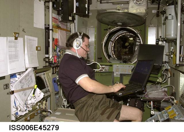
ISS006-E-45279 (21 March 2003) --- Cosmonaut Nikolai M. Budarin, Expedition Six flight engineer, uses a computer as he talks on a communication system in the Zvezda Service Module on the International Space Station (ISS). Budarin represents Rosaviakosmos.

iss073e0545108 (Aug. 26, 2025) --- Expedition 73 Flight Engineers (clockwise from top) Zena Cardman, Jonny Kim, and Mike Fincke, all three NASA astronauts, and Kimita Yui from JAXA (Japan Aerospace Exploration Agency) gather together inside the Kibo laboratory module prior to a conference with officials on the ground.
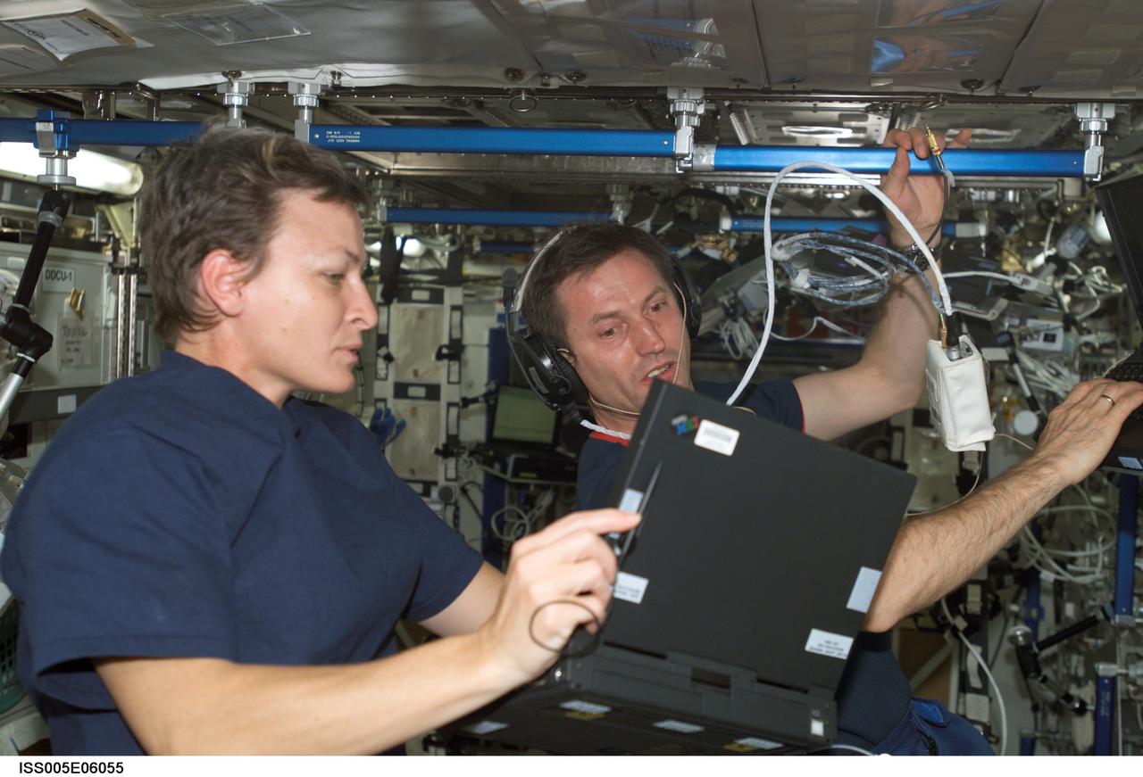
ISS005-E-06055 (27 June 2002) --- Astronaut Peggy A. Whitson (left) and cosmonaut Sergei Y. Treschev, both Expedition Five flight engineers, work in the Destiny laboratory on the International Space Station (ISS). Treschev represents Rosaviakosmos.
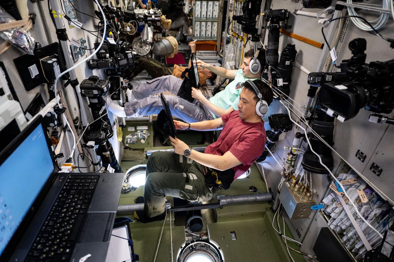
iss073e0221786 (June 20, 2025) --- From front to back, Expedition 73 Flight Engineers Jonny Kim of NASA and Alexey Zubritsky and Sergey Ryzhikov, both from Roscosmos, practice an emergency drill on computer tablets inside the International Space Station's Zvezda service module.
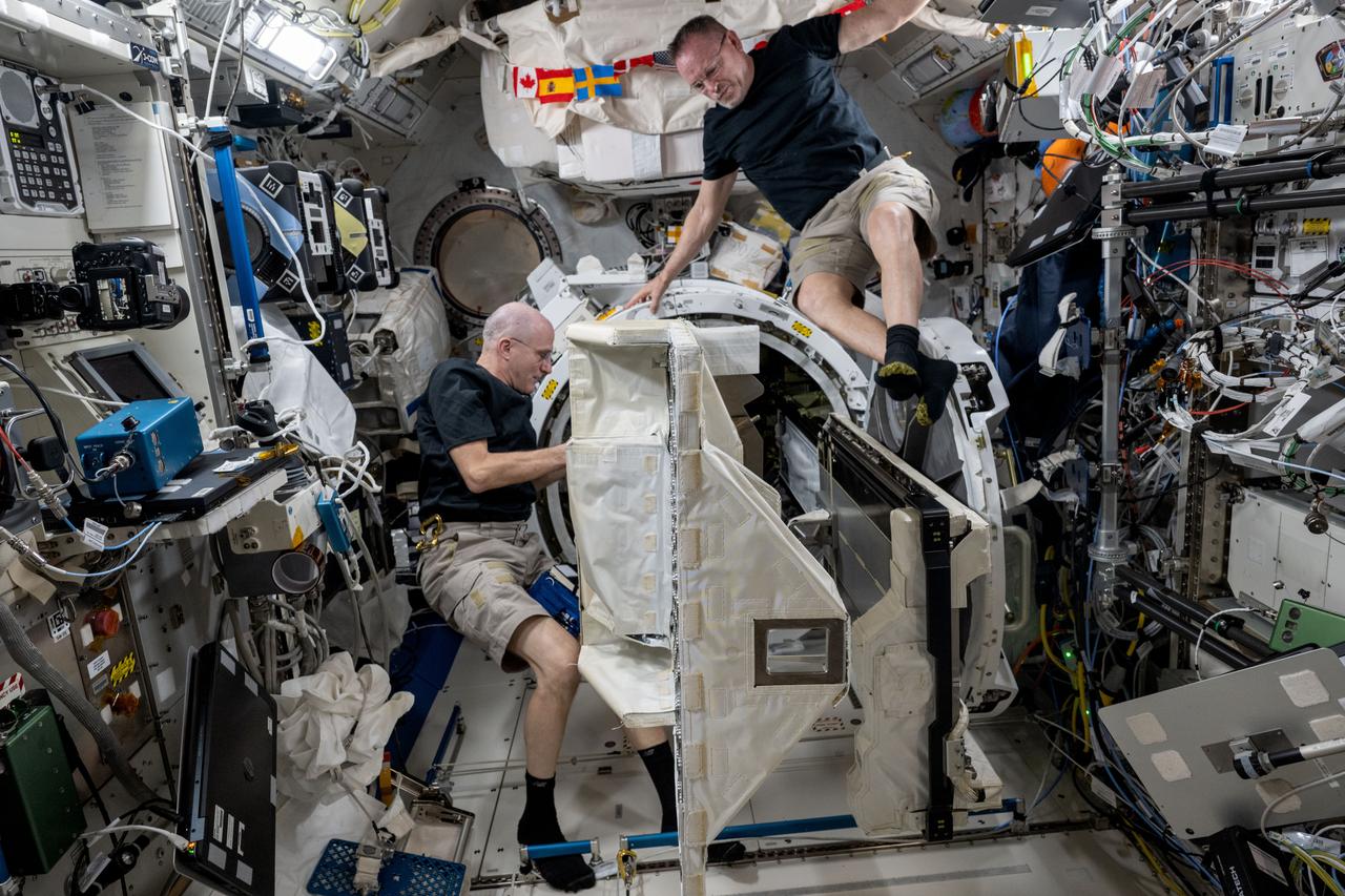
iss072e143154 (Oct. 30, 2024) --- Expedition 72 Flight Engineers (from left) Don Pettit and Butch Wilmore, both NASA astronauts, remove a small satellite deployer from inside the Kibo laboratory module's airlock that had earlier deployed several CubeSats into Earth orbit for a series of technology studies.
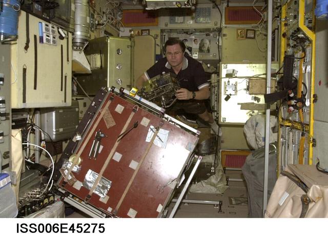
ISS006-E-45275 (21 March 2003) --- Cosmonaut Nikolai M. Budarin, Expedition Six flight engineer, holds a piece of hardware near a worktable in the Zvezda Service Module on the International Space Station (ISS). Budarin represents Rosaviakosmos.
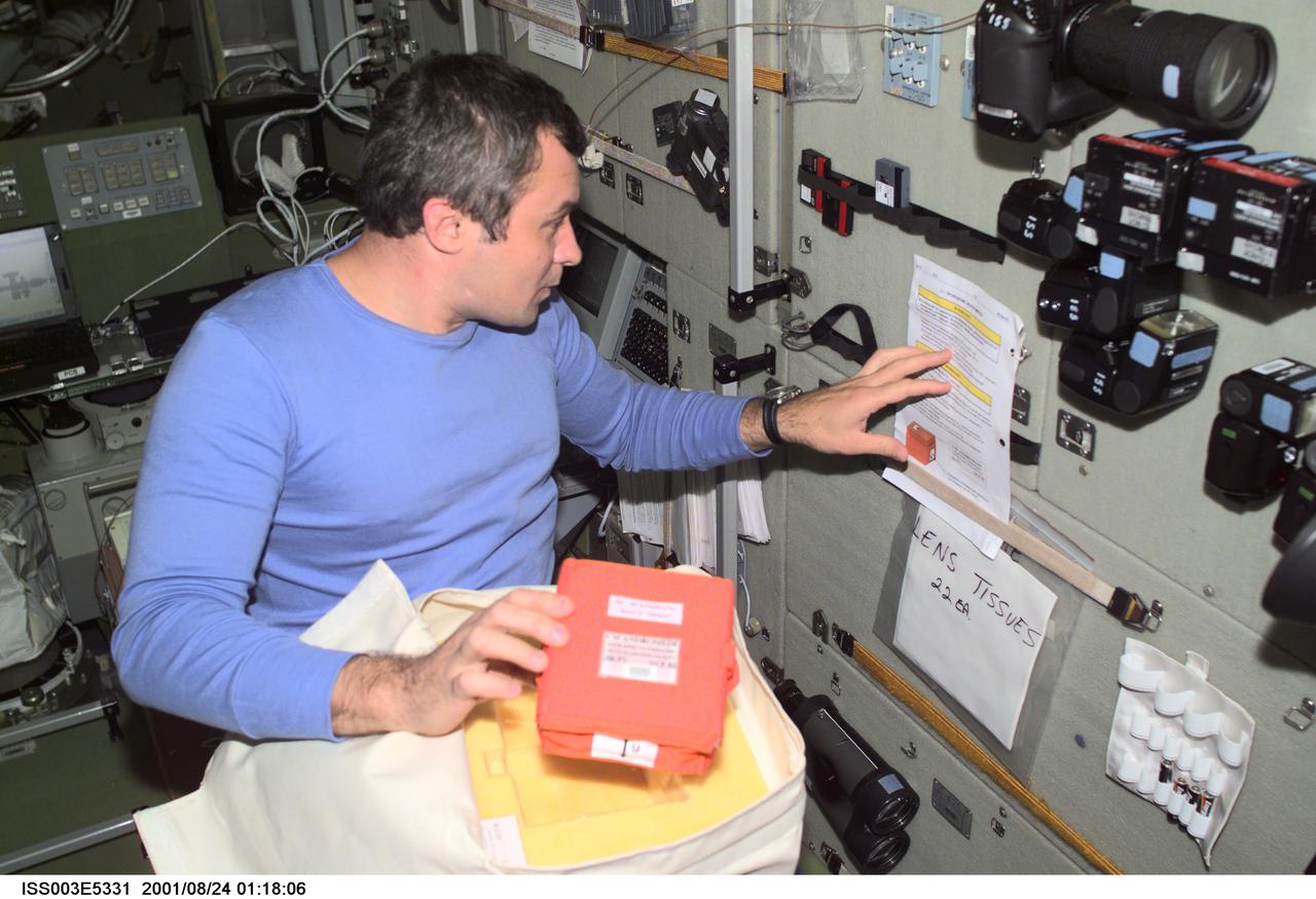
ISS003-E-5331 (24 August 2001) --- Cosmonaut Vladimir N. Dezhurov, flight engineer representing Rosaviakosmos, checks over a list of procedures in the Zvezda Service Module on the International Space Station (ISS). This image was taken with a digital still camera.
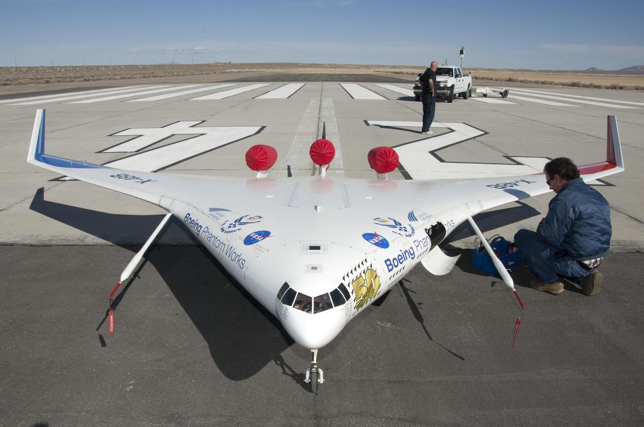
NASA Dryden engineer Gary Cosentino prepares the X-48B for flight.
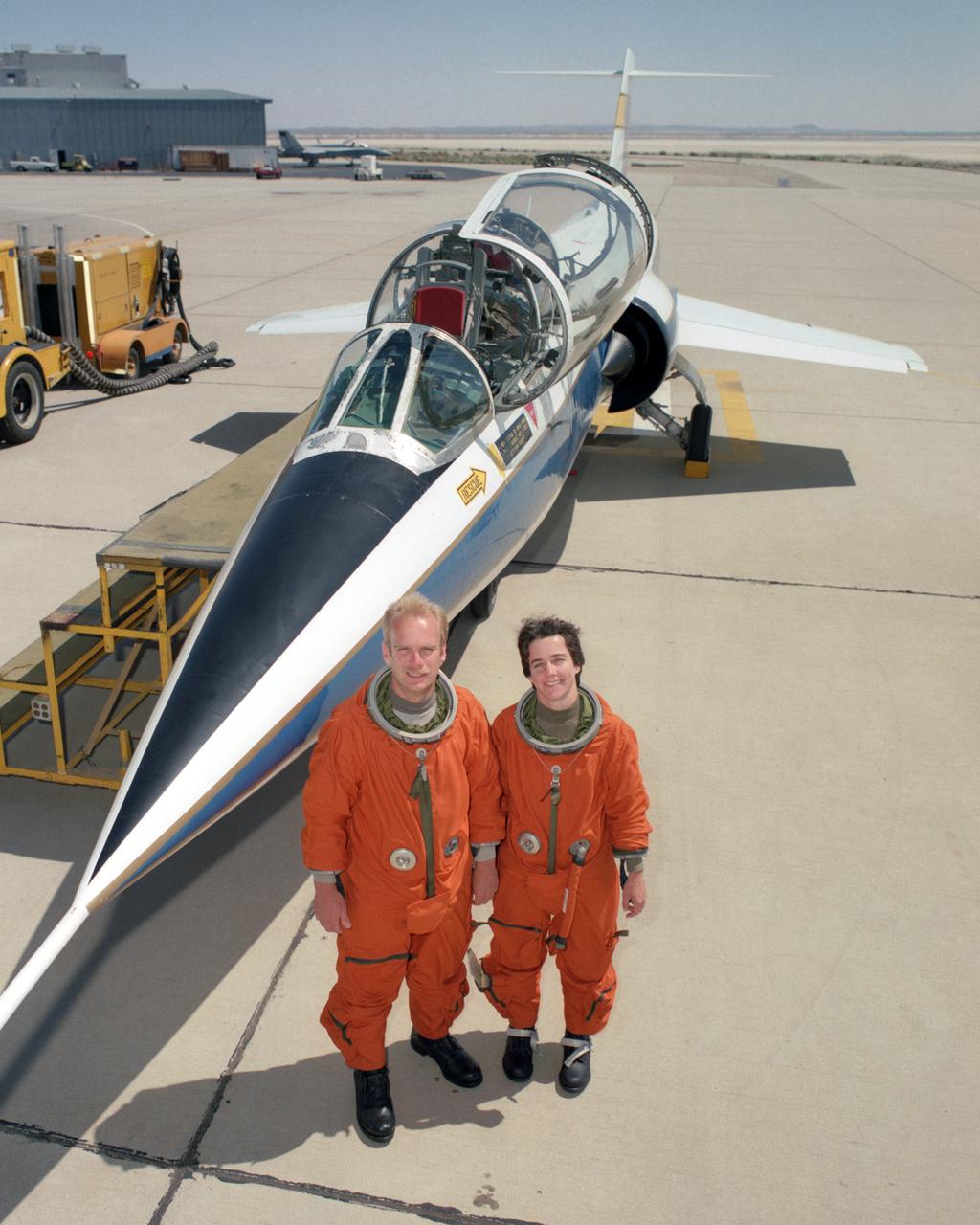
Flight test engineers Bob Meyer and Marta Bohn-Meyer had the distinction of being the only married couple to both serve on flight status on this two-seat F-104 at NASA Dryden.
NASA engineer Gary Cosentino communicates with fellow X-48B flight team personnel in preparation for another flight.
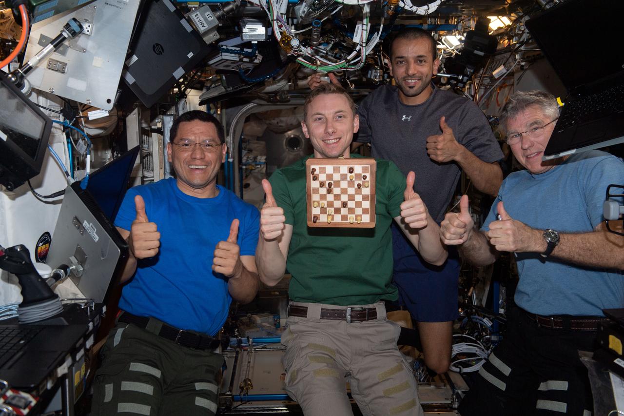
iss069e003898 (April 17, 2023) --- (From left) Expedition 69 Flight Engineers Frank Rubio, Woody Hoburg (both from NASA), Sultan Alneyadi from UAE (United Arab Emirates), and Stephen Bowen from NASA give a "thumbs up" after winning the first round of a space-to-ground chess tournament with mission controllers at NASA's Johnson Space Center in Houston, Texas. Hoburg is a chess fan and set up a chess tournament with mission controllers with each side having their own chess board and typically making one or two moves a day during their busy schedules.
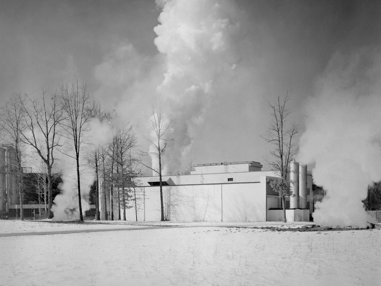
The Engine Propeller Research Building, referred to as the Prop House, emits steam from its acoustic silencers at the National Advisory Committee for Aeronautics (NACA) Lewis Flight Propulsion Laboratory. In 1942 the Prop House became the first completed test facility at the new NACA laboratory in Cleveland, Ohio. It contained four test cells designed to study large reciprocating engines. After World War II, the facility was modified to study turbojet engines. Two of the test cells were divided into smaller test chambers, resulting in a total of six engine stands. During this period the NACA Lewis Materials and Thermodynamics Division used four of the test cells to investigate jet engines constructed with alloys and other high temperature materials. The researchers operated the engines at higher temperatures to study stress, fatigue, rupture, and thermal shock. The Compressor and Turbine Division utilized another test cell to study a NACA-designed compressor installed on a full-scale engine. This design sought to increase engine thrust by increasing its airflow capacity. The higher stage pressure ratio resulted in a reduction of the number of required compressor stages. The last test cell was used at the time by the Engine Research Division to study the effect of high inlet densities on a jet engine. Within a couple years of this photograph the Prop House was significantly altered again. By 1960 the facility was renamed the Electric Propulsion Research Building to better describe its new role in electric propulsion.
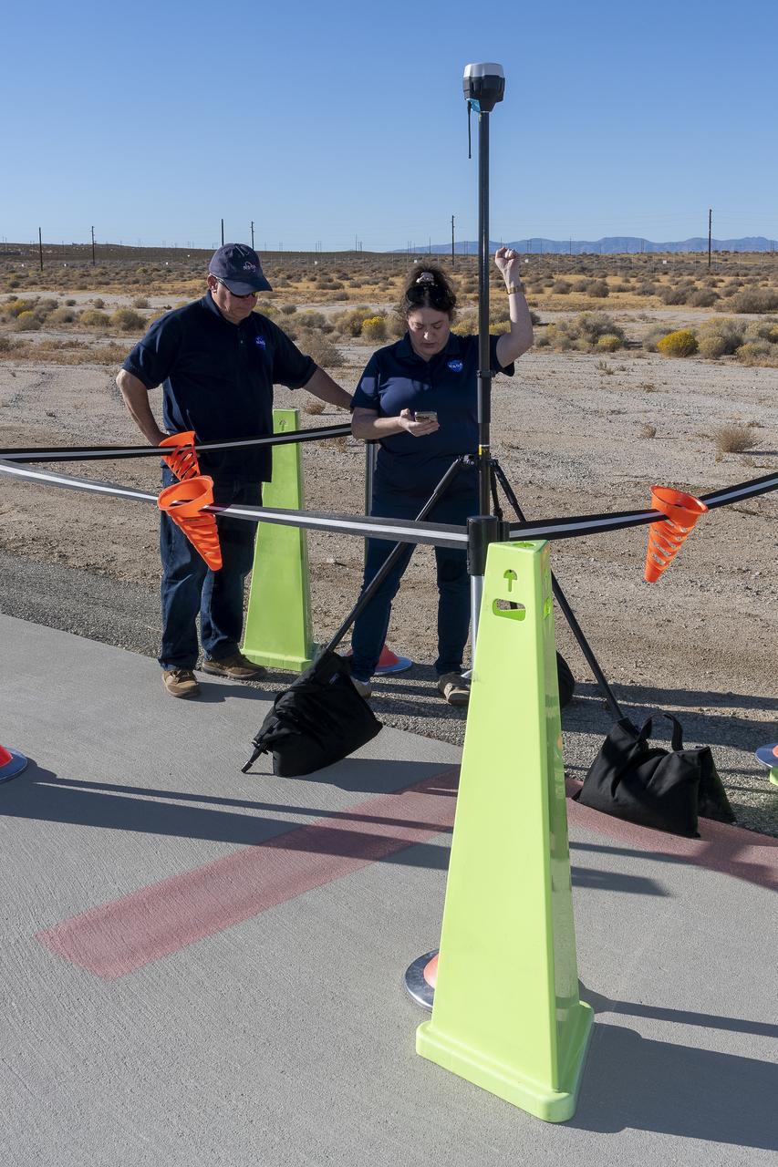
NASA Pathways intern Saré Culbertson, right, works with NASA operations engineer Jack Hayes at NASA’s Armstrong Flight Research Center in Edwards, California, on Nov. 7, 2024. They are verifying GPS and global navigation satellite system coordinates using Emlid Reach RS2+ receiver equipment, which supports surveying, mapping, and navigation in preparation for future air taxi test flight research.
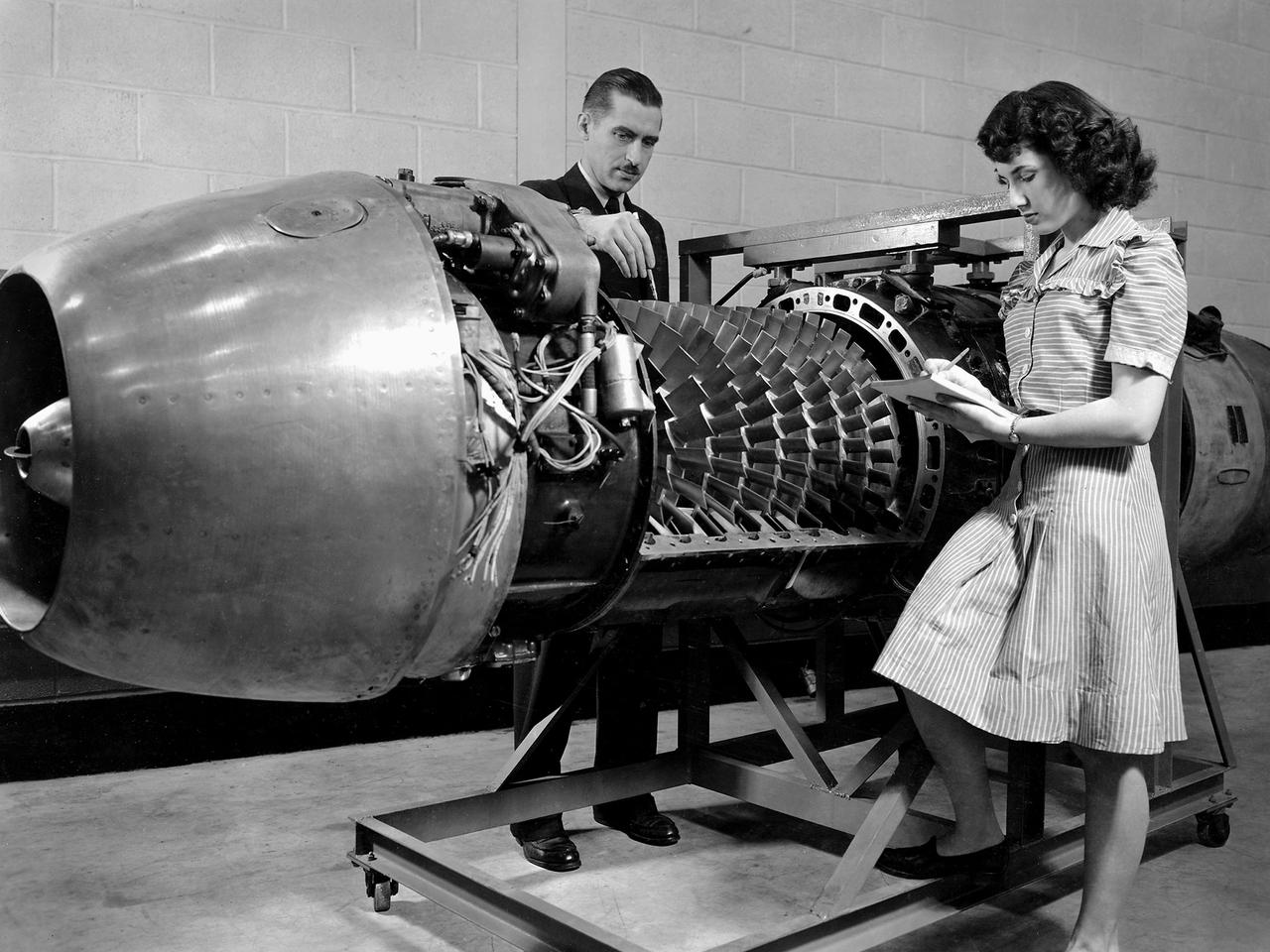
Researcher Robert Miller led an investigation into the combustor performance of a German Jumo 004 engine at the National Advisory Committee for Aeronautics (NACA) Lewis Flight Propulsion Laboratory. The Jumo 004 powered the world's first operational jet fighter, the Messerschmitt Me 262, beginning in 1942. The Me 262 was the only jet aircraft used in combat during World War II. The eight-stage axial-flow compressor Jumo 004 produced 2000 pounds of thrust. The US Army Air Forces provided the NACA with a Jumo 004 engine in 1945 to study the compressor’s design and performance. Conveniently the engine’s designer Anselm Franz had recently arrived at Wright-Patterson Air Force Base in nearby Dayton, Ohio as part of Project Paperclip. The Lewis researchers used a test rig in the Engine Research Building to analyze one of the six combustion chambers. It was difficult to isolate a single combustor’s performance when testing an entire engine. The combustion efficiency, outlet-temperature distribution, and total pressure drop were measured. The researchers determined the Jumo 004’s maximum performance was 5000 revolutions per minute at a 27,000 foot altitude and 11,000 revolutions per minute at a 45,000 foot altitude. The setup in this photograph was created for a tour of NACA Lewis by members of the Institute of Aeronautical Science on March 22, 1945.
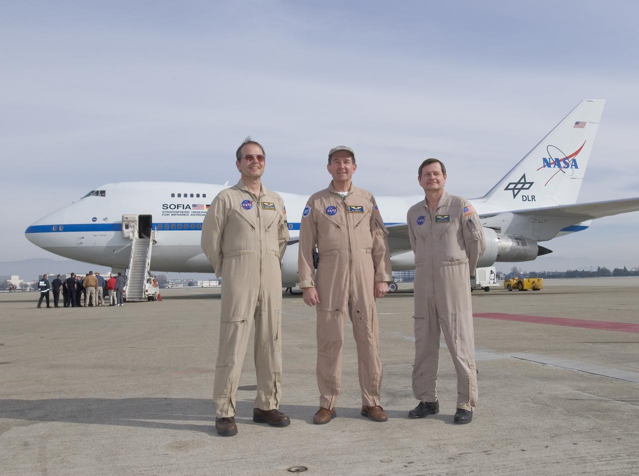
The flight crew of NASA's SOFIA airborne observatory includes (from left), flight engineer Marty Trout and pilots Bill Brockett and Frank Batteas.

A mechanic works on a General Electric I-40 turbojet at the National Advisory Committee for Aeronautics (NACA) Lewis Flight Propulsion Laboratory. The military selected General Electric’s West Lynn facility in 1941 to secretly replicate the centrifugal turbojet engine designed by British engineer Frank Whittle. General Electric’s first attempt, the I-A, was fraught with problems. The design was improved somewhat with the subsequent I-16 engine. It was not until the engine's next reincarnation as the I-40 in 1943 that General Electric’s efforts paid off. The 4000-pound thrust I-40 was incorporated into the Lockheed Shooting Star airframe and successfully flown in June 1944. The Shooting Star became the US’s first successful jet aircraft and the first US aircraft to reach 500 miles per hour. The NACA’s Lewis Flight Propulsion Laboratory studied all of General Electric’s centrifugal turbojets both during World War II and afterwards. The entire Shooting Star aircraft was investigated in the Altitude Wind Tunnel during 1945. The researchers studied the engine compressor performance, thrust augmentation using a water injection, and compared different fuel blends in a single combustor. The mechanic in this photograph is inserting a combustion liner into one of the 14 combustor cans. The compressor, which is not yet installed in this photograph, pushed high pressure air into these combustors. There the air mixed with the fuel and was heated. The hot air was then forced through a rotating turbine that powered the engine before being expelled out the nozzle to produce thrust.
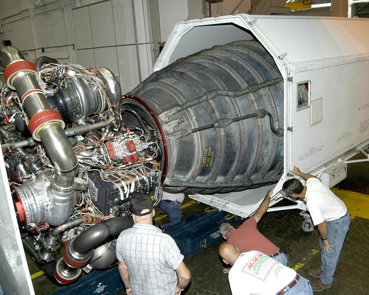
On Oct. 5, 2004, SSC shipped the last of the three Space Shuttle Main Engines to NASA's Kennedy Space Center for installation on Space Shuttle Discovery for STS-114, NASA's Return to Flight mission.

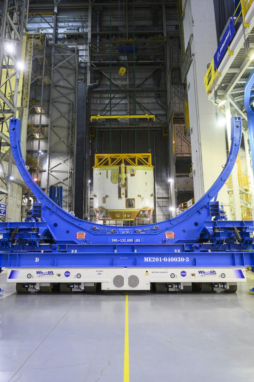
Technicians at NASA’s Michoud Assembly Facility in New Orleans moved the engine section of NASA’s Space Launch System (SLS) rocket for Artemis II, the first crewed mission to the Moon, into position for the final join of the core stage Feb. 13. The engine section is the bottom-most portion of the 212-foot-tall core stage. It is the last of five major elements that is needed to connect the stage into one major structure. In addition to its miles of cabling and hundreds of sensors, the engine section is a crucial attachment point for the four RS-25 engines and two solid rocket boosters that produce a combined 8.8 million pounds of thrust at liftoff and flight. During launch and flight, liquid propellants from the liquid hydrogen tank and liquid oxygen tanks are delivered through the engine section to the four RS-25 engines. The engine section also includes the avionics that help steer the engines after liftoff. Next, teams will join the engine section to the core stage for the second SLS rocket. After the join is complete, teams will begin to add each of the four RS-25 engines one by one to complete the stage. The completely assembled stage with its four RS-25 engines will be shipped to NASA’s Kennedy Space Center in Florida later this year. The SLS rocket is the only rocket capable of carrying astronauts in Orion around the Moon in a single mission. Image credit: NASA/Michael DeMocker

Technicians at NASA’s Michoud Assembly Facility in New Orleans moved the engine section of NASA’s Space Launch System (SLS) rocket for Artemis II, the first crewed mission to the Moon, into position for the final join of the core stage Feb. 13. The engine section is the bottom-most portion of the 212-foot-tall core stage. It is the last of five major elements that is needed to connect the stage into one major structure. In addition to its miles of cabling and hundreds of sensors, the engine section is a crucial attachment point for the four RS-25 engines and two solid rocket boosters that produce a combined 8.8 million pounds of thrust at liftoff and flight. During launch and flight, liquid propellants from the liquid hydrogen tank and liquid oxygen tanks are delivered through the engine section to the four RS-25 engines. The engine section also includes the avionics that help steer the engines after liftoff. Next, teams will join the engine section to the core stage for the second SLS rocket. After the join is complete, teams will begin to add each of the four RS-25 engines one by one to complete the stage. The completely assembled stage with its four RS-25 engines will be shipped to NASA’s Kennedy Space Center in Florida later this year. The SLS rocket is the only rocket capable of carrying astronauts in Orion around the Moon in a single mission. Image credit: NASA/Michael DeMocker

Technicians at NASA’s Michoud Assembly Facility in New Orleans moved the engine section of NASA’s Space Launch System (SLS) rocket for Artemis II, the first crewed mission to the Moon, into position for the final join of the core stage Feb. 13. The engine section is the bottom-most portion of the 212-foot-tall core stage. It is the last of five major elements that is needed to connect the stage into one major structure. In addition to its miles of cabling and hundreds of sensors, the engine section is a crucial attachment point for the four RS-25 engines and two solid rocket boosters that produce a combined 8.8 million pounds of thrust at liftoff and flight. During launch and flight, liquid propellants from the liquid hydrogen tank and liquid oxygen tanks are delivered through the engine section to the four RS-25 engines. The engine section also includes the avionics that help steer the engines after liftoff. Next, teams will join the engine section to the core stage for the second SLS rocket. After the join is complete, teams will begin to add each of the four RS-25 engines one by one to complete the stage. The completely assembled stage with its four RS-25 engines will be shipped to NASA’s Kennedy Space Center in Florida later this year. The SLS rocket is the only rocket capable of carrying astronauts in Orion around the Moon in a single mission. Image credit: NASA/Michael DeMocker

Technicians at NASA’s Michoud Assembly Facility in New Orleans moved the engine section of NASA’s Space Launch System (SLS) rocket for Artemis II, the first crewed mission to the Moon, into position for the final join of the core stage Feb. 13. The engine section is the bottom-most portion of the 212-foot-tall core stage. It is the last of five major elements that is needed to connect the stage into one major structure. In addition to its miles of cabling and hundreds of sensors, the engine section is a crucial attachment point for the four RS-25 engines and two solid rocket boosters that produce a combined 8.8 million pounds of thrust at liftoff and flight. During launch and flight, liquid propellants from the liquid hydrogen tank and liquid oxygen tanks are delivered through the engine section to the four RS-25 engines. The engine section also includes the avionics that help steer the engines after liftoff. Next, teams will join the engine section to the core stage for the second SLS rocket. After the join is complete, teams will begin to add each of the four RS-25 engines one by one to complete the stage. The completely assembled stage with its four RS-25 engines will be shipped to NASA’s Kennedy Space Center in Florida later this year. The SLS rocket is the only rocket capable of carrying astronauts in Orion around the Moon in a single mission. Image credit: NASA/Michael DeMocker
iss072e861347 (March 28, 2025) --- Clockwise from left, are Expedition 72 Flight Engineers Takuya Onishi from JAXA (Japan Aerospace Exploration Agency) and Anne McClain, Nichole Ayers, and Don Pettit, all three from NASA. The quartet is posing inside the vestibule between the International Space Station's Unity module and the Cygnus space freighter that would depart the orbital outpost soon after this photograph was taken.
iss073e1228220 (Dec. 2, 2025) --- Expedition 73 Flight Engineers (from left) Chris Williams and Jonny Kim, both NASA astronauts, work together inspecting and cleaning the Enhanced European Exploration Exercise Device (E4D) inside the International Space Station's Columbus laboratory. The E4D is being tested on the orbital outpost for its ability to provide bicycling, rowing, and resistance exercises to protect a crew member’s muscles, bones, and heart health in microgravity.
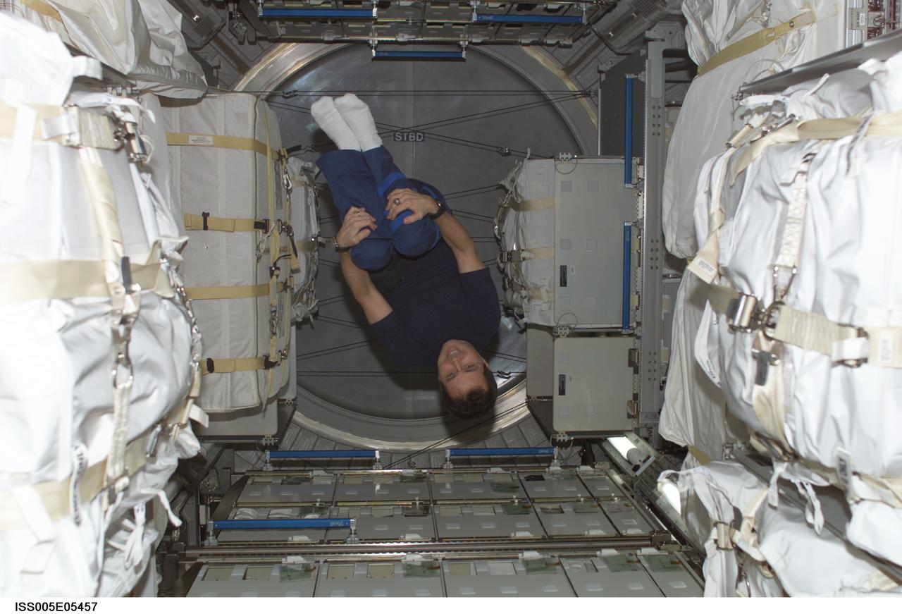
ISS005-E-05457 (June 2002) --- Astronaut Daniel W. Bursch, Expedition Four flight engineer, floats in the Leonardo Multi-Purpose Logistics Module (MPLM). Leonardo is one of three Multi-Purpose Logistics Modules built by the Italian Space Agency that serve as pressurized, reusable cargo carriers to ferry supplies, equipment and experiments between the ground and the space station.
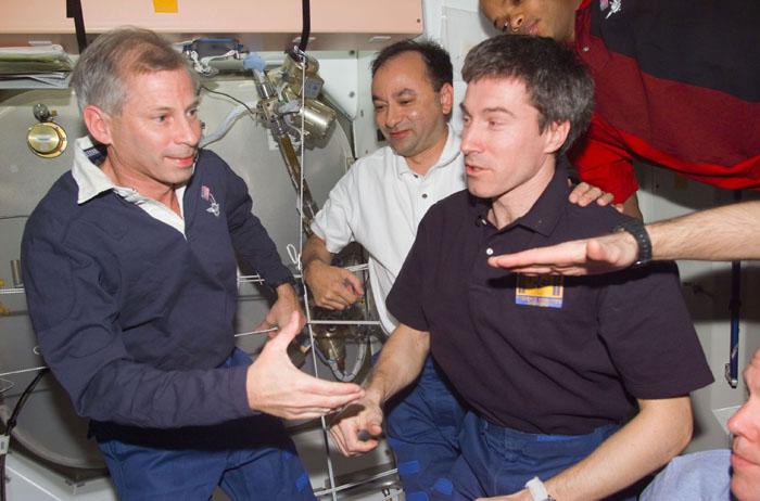
STS98-E-5295 (16 February 2001) --- Astronaut Kenneth D. Cockrell (left), STS-98 mission commander, participates in farewells with Expedition One crew members. Cosmonaut Sergei K. Krikalev (right foreground), Expedition One flight engineer, is one of three crew members who will stay behind for several weeks prior to return to Earth. Astronauts Mark L. Polansky, STS-98 pilot, and Robert L. Curbeam, mission specialist, are also pictured. The scene was recorded with a digital still camera.
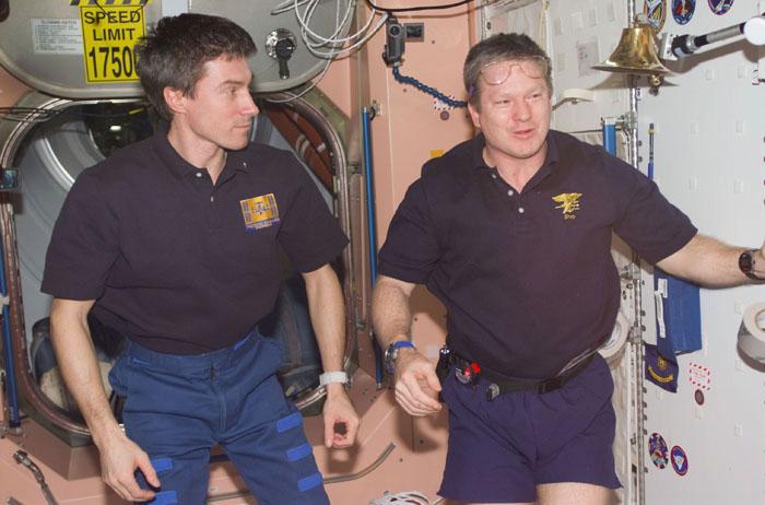
STS98-E-5291 (16 February 2001) --- Cosmonaut Sergei K. Krikalev (left), Expedition One flight engineer representing the Russian Aviation and Space Agency, and astronaut William M. (Bill) Shepherd, Expedition One commander, look toward their astronaut visitors (out of frame), about to conclude their time on the outpost. The scene was recorded with a digital still camera during farewells in the Unity node.
iss073e1199016 (Nov. 20, 2025) --- Expedition 73 Flight Engineers (from left) Kimiya Yui of JAXA (Japan Aerospace Exploration Agency) and Jonny Kim of NASA work together swapping thermal control system hoses on the COLBERT treadmill located inside the Tranquility module. The pair temporarily uninstalled the station’s bathroom, or waste and hygiene compartment, to access the life support hoses.

NASA Armstrong’s Mission Control Center, or MCC, is where culmination of all data-gathering occurs. Engineers, flight controllers and researchers monitor flights and missions as they are carried out. Data and video run through the MCC and are recorded, displayed and archived. Data is then processed and prepared for post-flight analysis.

STS113-E-05023 (25 November 2002) --- Astronaut Donald R. Pettit, Expedition Six flight engineer, holds a camera on the aft flight deck of the Space Shuttle Endeavour.
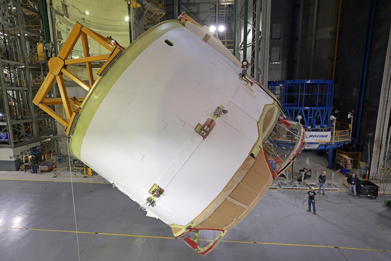
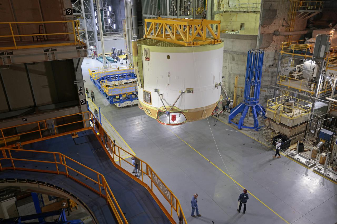
Technicians at NASA’s Michoud Assembly Facility in New Orleans flipped the engine section of NASA’s Space Launch System rocket for Artemis II from a vertical to a horizontal position Feb. 11. The flip, also known as a breakover, is in preparation for the final assembly and integration into the core stage for the second SLS rocket. The engine section is the bottom-most portion of the 212-foot-tall core stage and is one of the most complex and intricate portions of the rocket that will help power the first crewed Artemis mission to the Moon. It is the last of five elements that is needed to join the stage as one structure. In addition to its miles of cabling and hundreds of sensors, the engine section is a crucial attachment point for the four RS-25 engines and two solid rocket boosters that produce a combined 8.8 million pounds of thrust at liftoff and flight. Next, teams will move the engine section into the final assembly area where they will complete the join. After the join is complete, teams will begin to add each of the four RS-25 engines. The completely assembled stage with its four RS-25 engines will be shipped to NASA’s Kennedy Space Center in Florida later this year. The SLS rocket is the only rocket capable of carrying astronauts in Orion around the Moon in a single mission. Image credit: NASA/Michael DeMocker
Technicians at NASA’s Michoud Assembly Facility in New Orleans flipped the engine section of NASA’s Space Launch System rocket for Artemis II from a vertical to a horizontal position Feb. 11. The flip, also known as a breakover, is in preparation for the final assembly and integration into the core stage for the second SLS rocket. The engine section is the bottom-most portion of the 212-foot-tall core stage and is one of the most complex and intricate portions of the rocket that will help power the first crewed Artemis mission to the Moon. It is the last of five elements that is needed to join the stage as one structure. In addition to its miles of cabling and hundreds of sensors, the engine section is a crucial attachment point for the four RS-25 engines and two solid rocket boosters that produce a combined 8.8 million pounds of thrust at liftoff and flight. Next, teams will move the engine section into the final assembly area where they will complete the join. After the join is complete, teams will begin to add each of the four RS-25 engines. The completely assembled stage with its four RS-25 engines will be shipped to NASA’s Kennedy Space Center in Florida later this year. The SLS rocket is the only rocket capable of carrying astronauts in Orion around the Moon in a single mission. Image credit: NASA/Eric Bordelon
Technicians at NASA’s Michoud Assembly Facility in New Orleans flipped the engine section of NASA’s Space Launch System rocket for Artemis II from a vertical to a horizontal position Feb. 11. The flip, also known as a breakover, is in preparation for the final assembly and integration into the core stage for the second SLS rocket. The engine section is the bottom-most portion of the 212-foot-tall core stage and is one of the most complex and intricate portions of the rocket that will help power the first crewed Artemis mission to the Moon. It is the last of five elements that is needed to join the stage as one structure. In addition to its miles of cabling and hundreds of sensors, the engine section is a crucial attachment point for the four RS-25 engines and two solid rocket boosters that produce a combined 8.8 million pounds of thrust at liftoff and flight. Next, teams will move the engine section into the final assembly area where they will complete the join. After the join is complete, teams will begin to add each of the four RS-25 engines. The completely assembled stage with its four RS-25 engines will be shipped to NASA’s Kennedy Space Center in Florida later this year. The SLS rocket is the only rocket capable of carrying astronauts in Orion around the Moon in a single mission. Image credit: NASA/Michael DeMocker

Technicians at NASA’s Michoud Assembly Facility in New Orleans flipped the engine section of NASA’s Space Launch System rocket for Artemis II from a vertical to a horizontal position Feb. 11. The flip, also known as a breakover, is in preparation for the final assembly and integration into the core stage for the second SLS rocket. The engine section is the bottom-most portion of the 212-foot-tall core stage and is one of the most complex and intricate portions of the rocket that will help power the first crewed Artemis mission to the Moon. It is the last of five elements that is needed to join the stage as one structure. In addition to its miles of cabling and hundreds of sensors, the engine section is a crucial attachment point for the four RS-25 engines and two solid rocket boosters that produce a combined 8.8 million pounds of thrust at liftoff and flight. Next, teams will move the engine section into the final assembly area where they will complete the join. After the join is complete, teams will begin to add each of the four RS-25 engines. The completely assembled stage with its four RS-25 engines will be shipped to NASA’s Kennedy Space Center in Florida later this year. The SLS rocket is the only rocket capable of carrying astronauts in Orion around the Moon in a single mission. Image credit: NASA/Eric Bordelon

Technicians at NASA’s Michoud Assembly Facility in New Orleans flipped the engine section of NASA’s Space Launch System rocket for Artemis II from a vertical to a horizontal position Feb. 11. The flip, also known as a breakover, is in preparation for the final assembly and integration into the core stage for the second SLS rocket. The engine section is the bottom-most portion of the 212-foot-tall core stage and is one of the most complex and intricate portions of the rocket that will help power the first crewed Artemis mission to the Moon. It is the last of five elements that is needed to join the stage as one structure. In addition to its miles of cabling and hundreds of sensors, the engine section is a crucial attachment point for the four RS-25 engines and two solid rocket boosters that produce a combined 8.8 million pounds of thrust at liftoff and flight. Next, teams will move the engine section into the final assembly area where they will complete the join. After the join is complete, teams will begin to add each of the four RS-25 engines. The completely assembled stage with its four RS-25 engines will be shipped to NASA’s Kennedy Space Center in Florida later this year. The SLS rocket is the only rocket capable of carrying astronauts in Orion around the Moon in a single mission. Image credit: NASA/Michael DeMocker
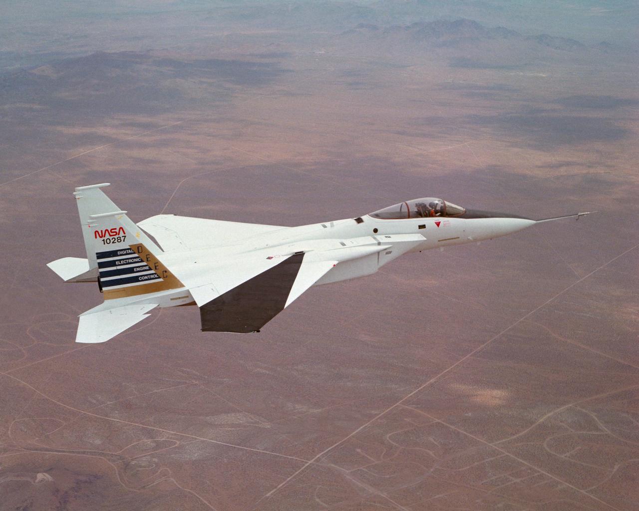
Digital Electronic Engine Control F-15A #287 in flight over California City. Note wing deflection measurement system on right wing.