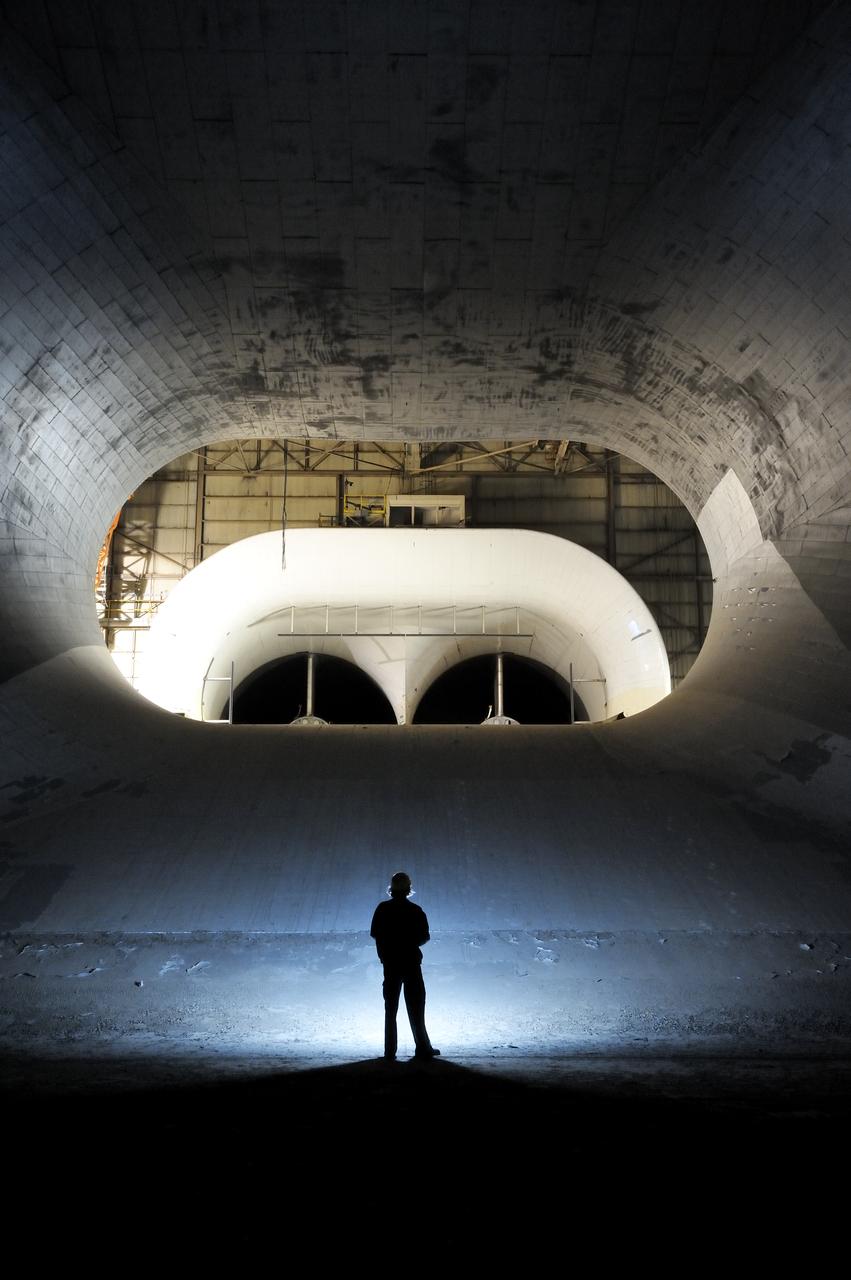
Full Scale Tunnel before demolition in 2011
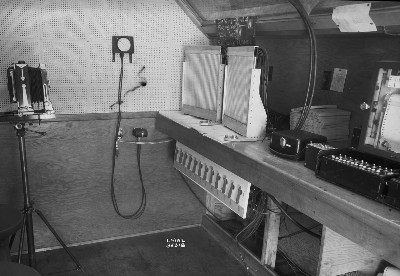
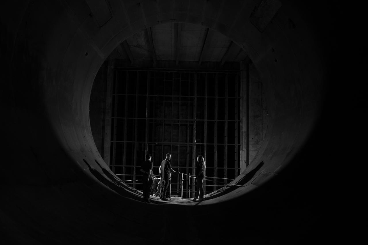
Instrumentation in Full Scale Tunnel
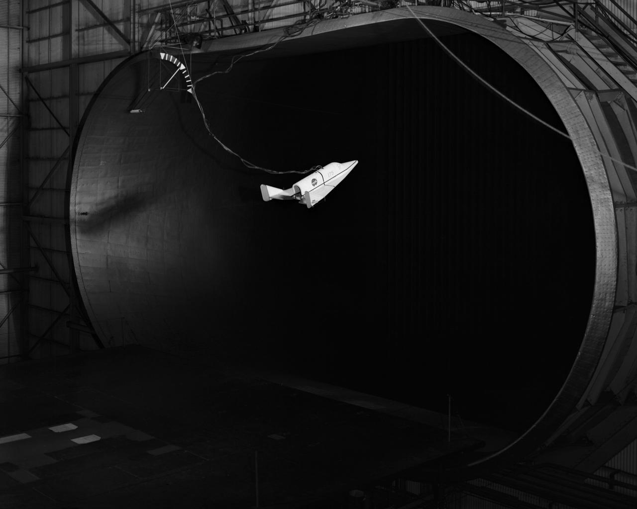
Dyna-Soar Model In Full Scale Tunnel
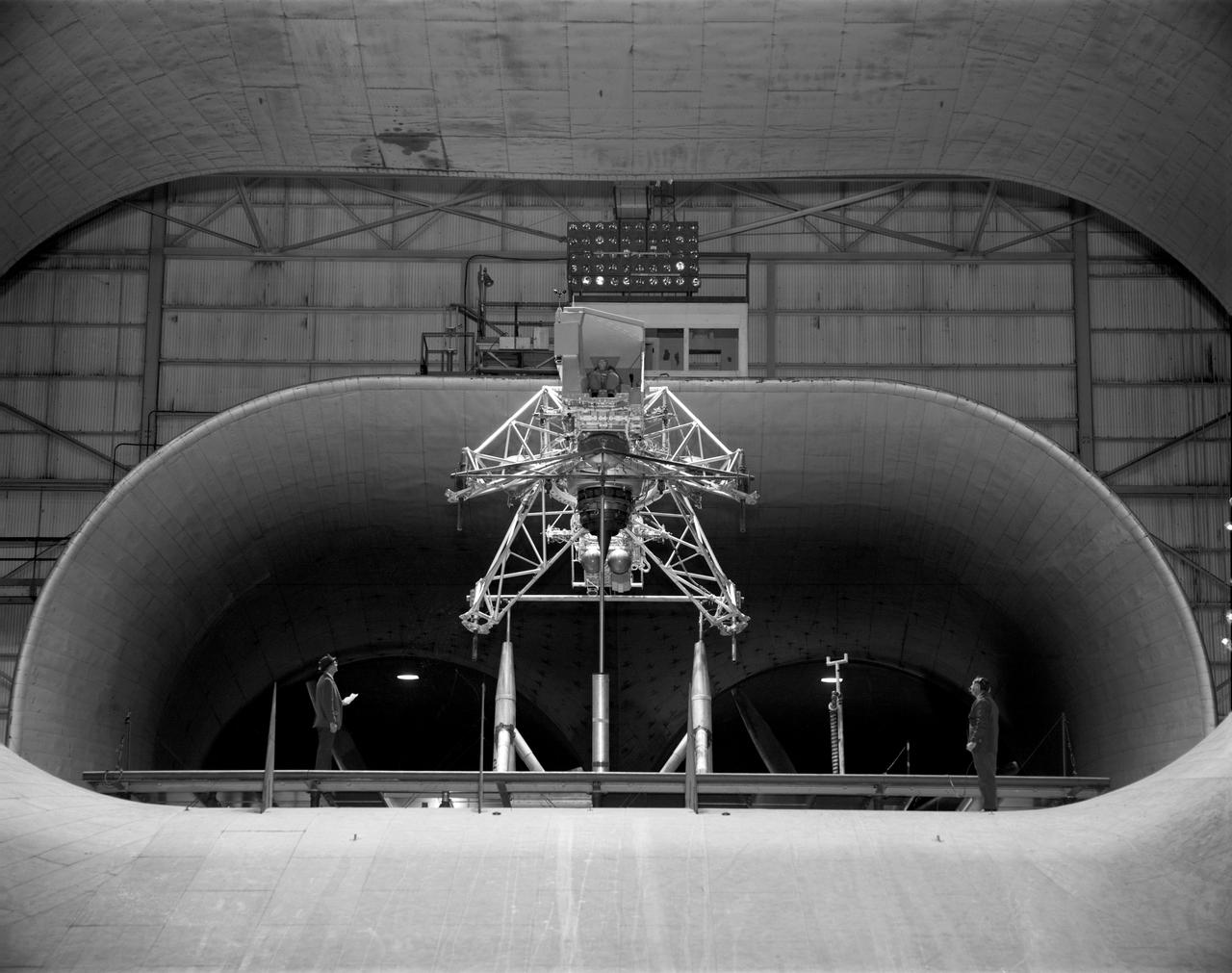
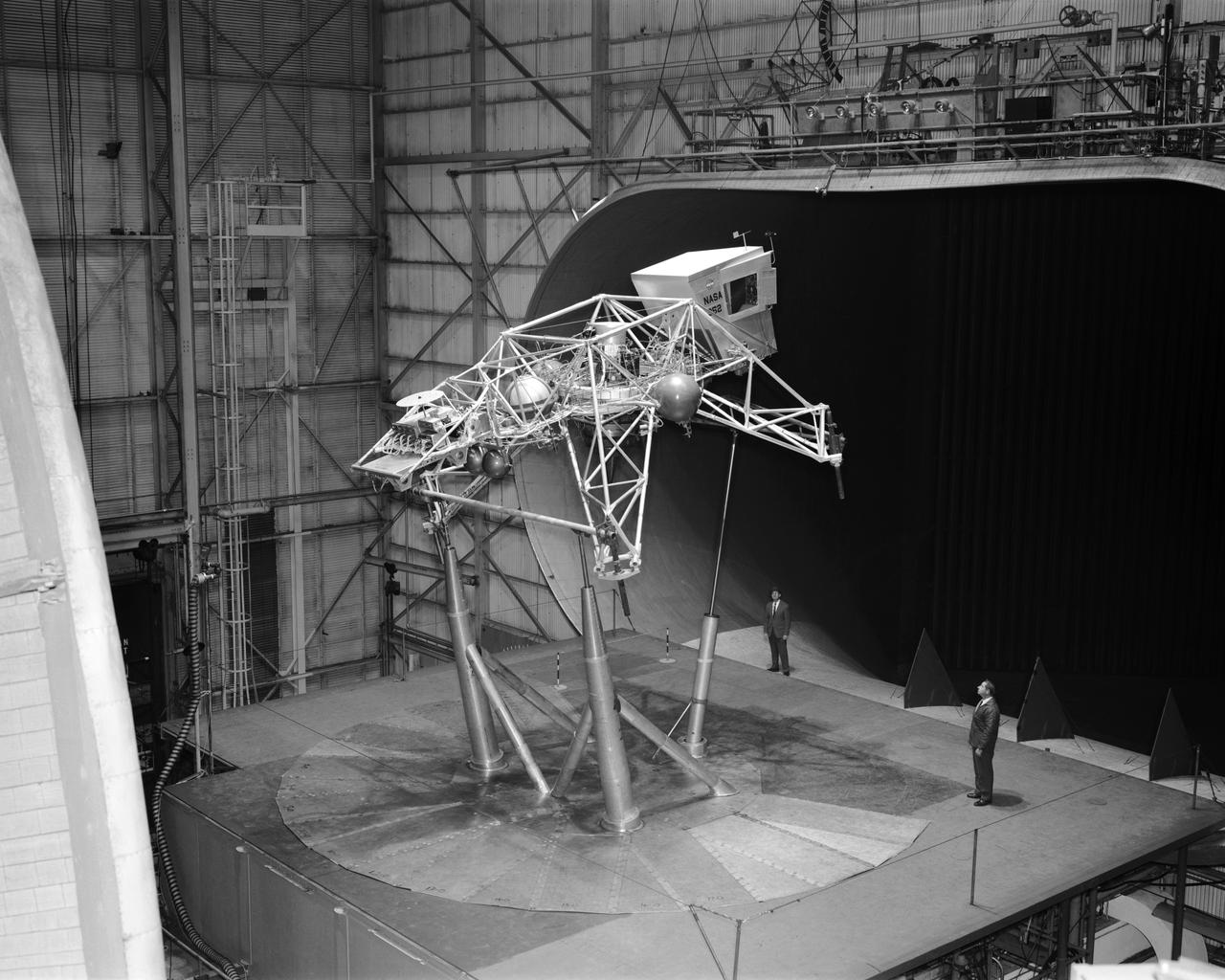
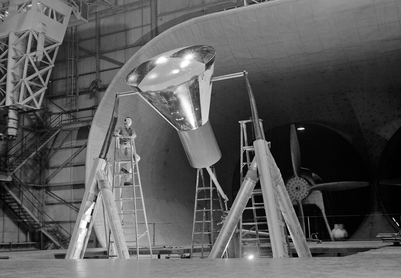
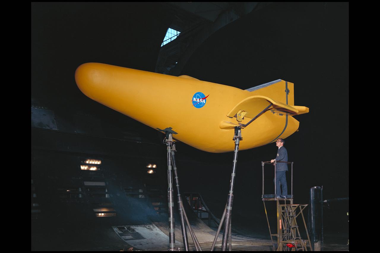
Concept model of the Lunar Excursion Module tested in the Full-Scale wind tunnel. -- Published in James R. Hansen, Spaceflight Revolution: NASA Langley Research Center From Sputnik to Apollo, (Washington: NASA, 1995), p. 356.-L69-670 Bell Lunar Landing Training Vehicle (LLTV): Following the crash of a sister Lunar Landing Training Vehicle at Ellington Field in Houston, Texas, the LLTV NASA 952 was sent from Houston to Langley for tests in the 30 x 60 Full Scale Tunnel. The LLTV was returned to Houston for further training use a short time later. NASA 952 is now on exhibit at the Johnson Space Center in Houston, Texas.
Concept model of the Lunar Excursion Module tested in the Full-Scale wind tunnel. -- Published in James R. Hansen, Spaceflight Revolution: NASA Langley Research Center From Sputnik to Apollo, (Washington: NASA, 1995), p. 356.-L69-670 Bell Lunar Landing Training Vehicle (LLTV): Following the crash of a sister Lunar Landing Training Vehicle at Ellington Field in Houston, Texas, the LLTV NASA 952 was sent from Houston to Langley for tests in the 30 x 60 Full Scale Tunnel. The LLTV was returned to Houston for further training use a short time later. NASA 952 is now on exhibit at the Johnson Space Center in Houston, Texas.
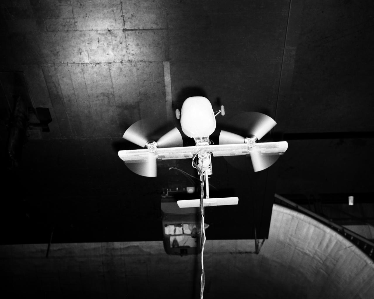
Vertical model flying in Langley Research Center's Full Scale Tunnel.
Vertical model flying in Langley Research Center's Full Scale Tunnel.
Vertical model flying in Langley Research Center's Full Scale Tunnel.
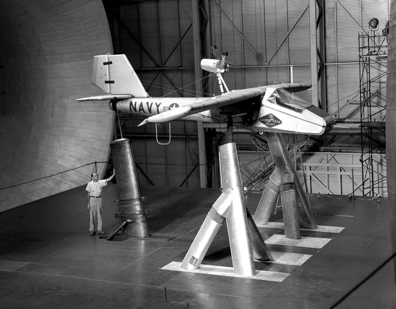
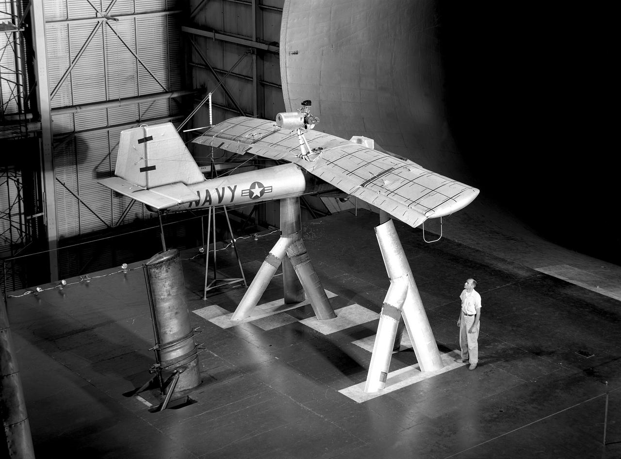
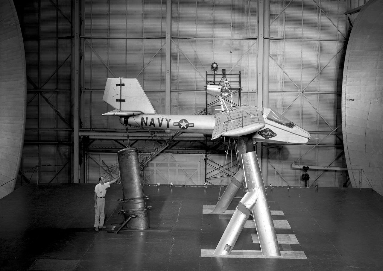
Various Components of Goodyear Inflatable Airplane in Full Scale Tunnel building 643 Test 238
Various Components of Goodyear Inflatable Airplane in Full Scale Tunnel building 643 Test 238
Various Components of Goodyear Inflatable Airplane in Full Scale Tunnel building 643 Test 238
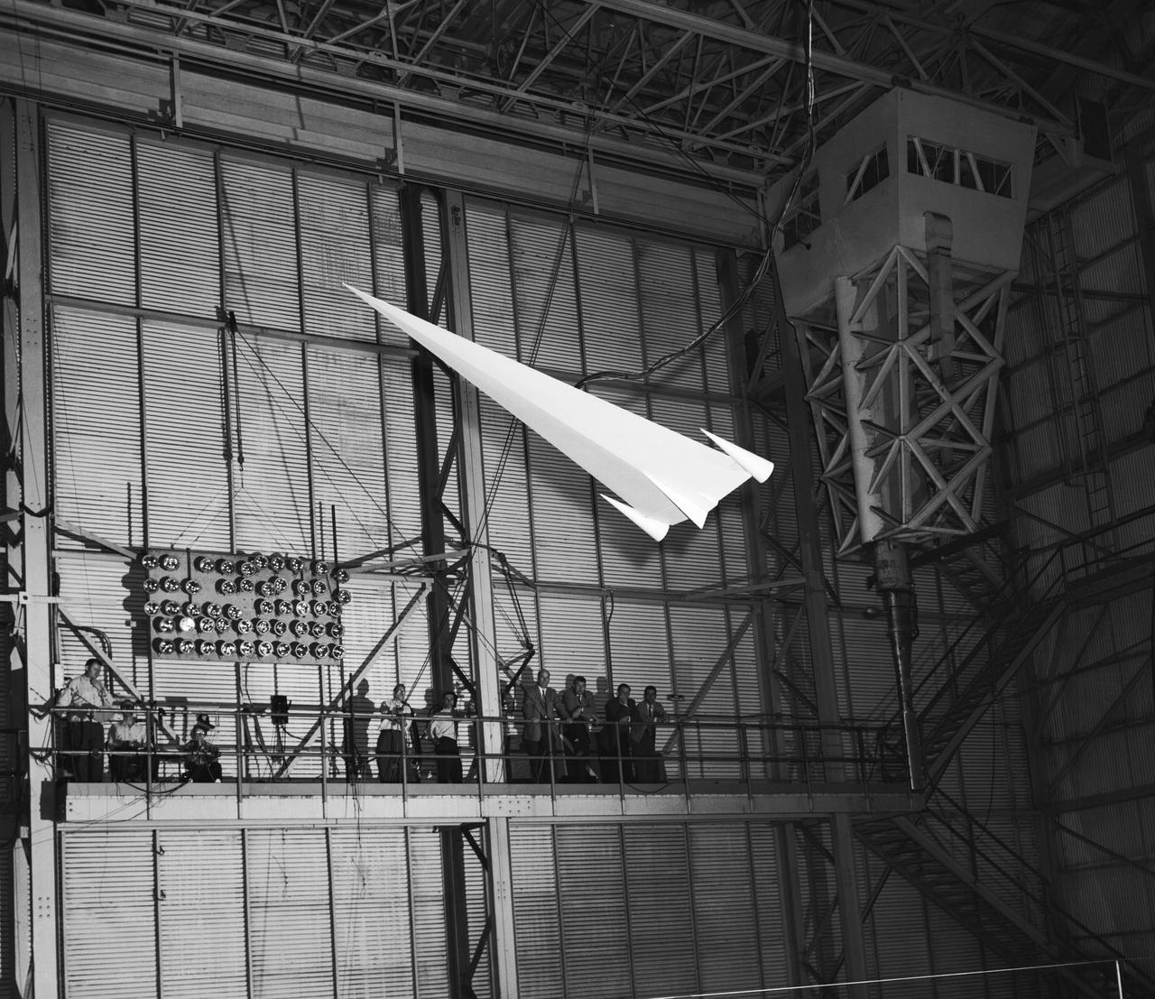
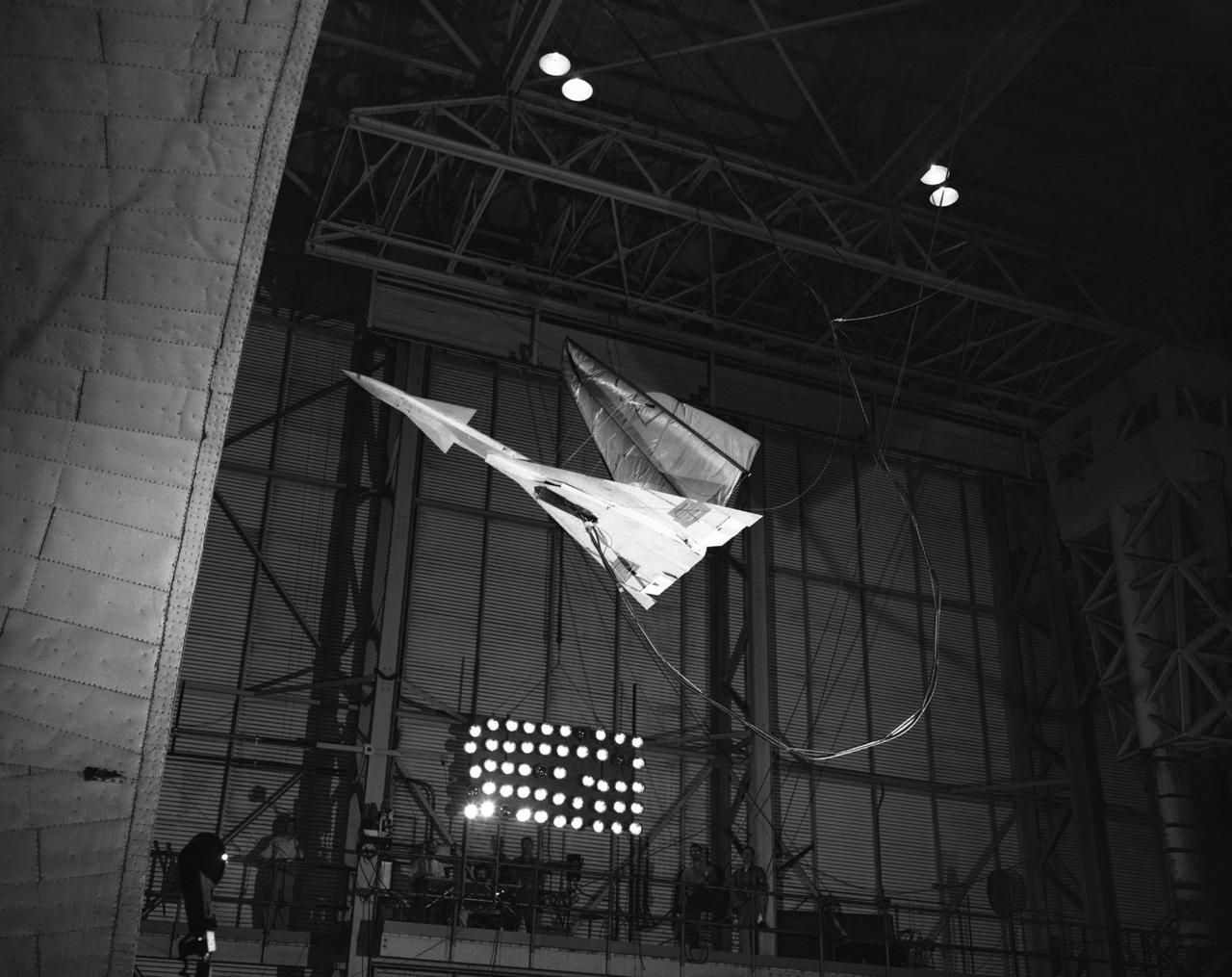
L57-1439 A model based on Langley s concept of a hypersonic glider was test flown on an umbilical cord inside the Full Scale Tunnel in 1957. Photograph published in Engineer in Charge: A History of the Langley Aeronautical Laboratory, 1917-1958 by James R. Hansen. Page 374.
The Mercury space capsule undergoing tests in Full Scale Wind Tunnel, January 1959. Photograph published in Winds of Change, 75th Anniversary NASA publication, page 75, by James Schultz. Also Photograph published in Engineer in Charge: A History of the Langley Aeronautical Laboratory, 1917-1958, page 389, by James R. Hansen.
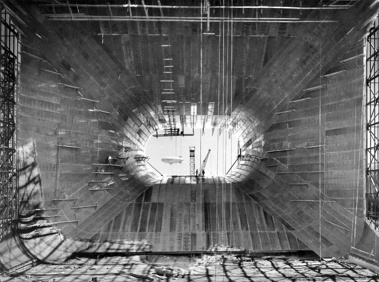
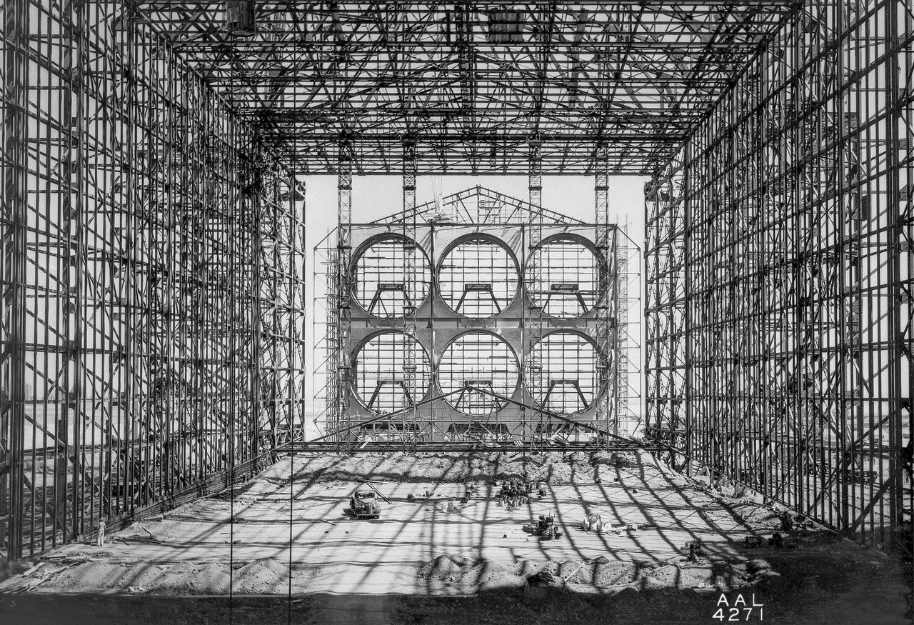
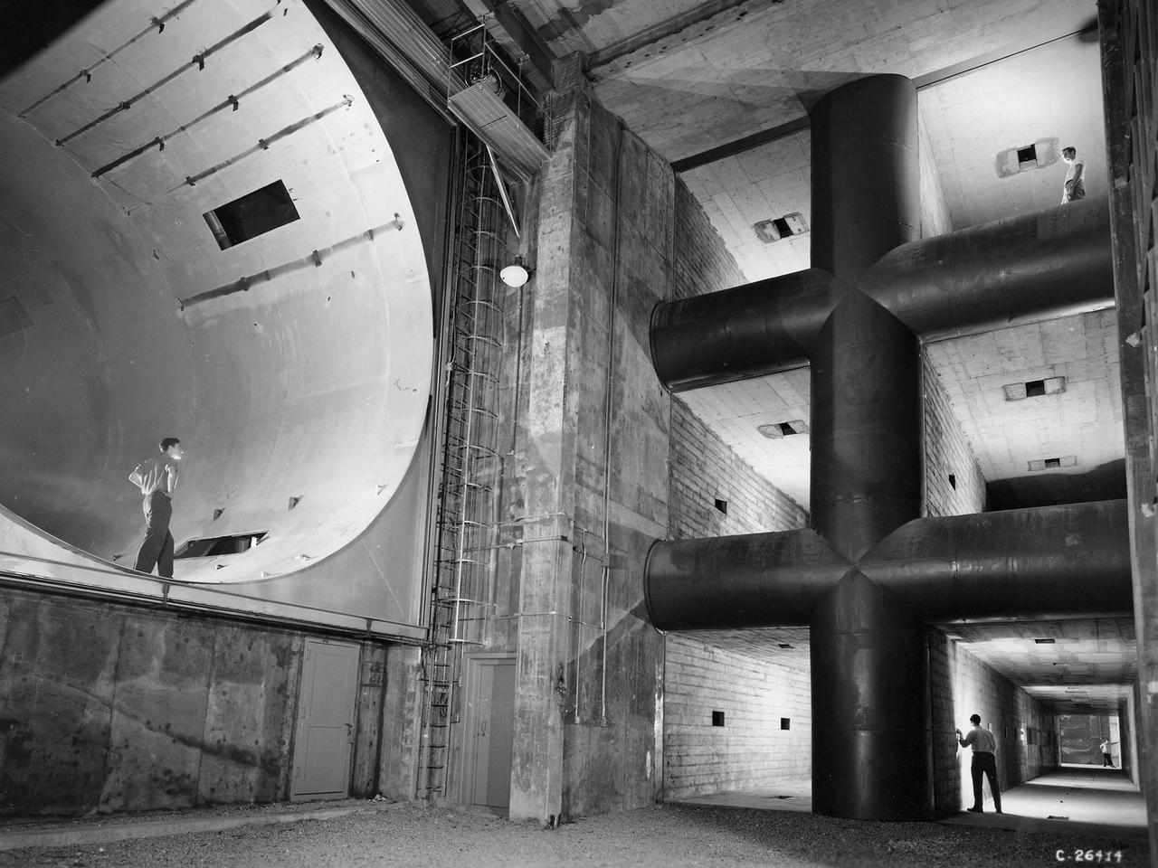
(07/07/1943) Construction view from inside the contraction framing of the 40x80 foot wind tunnel with a blimp flying in the background.
Kite model flying in Full Scale Tunnel (FST)
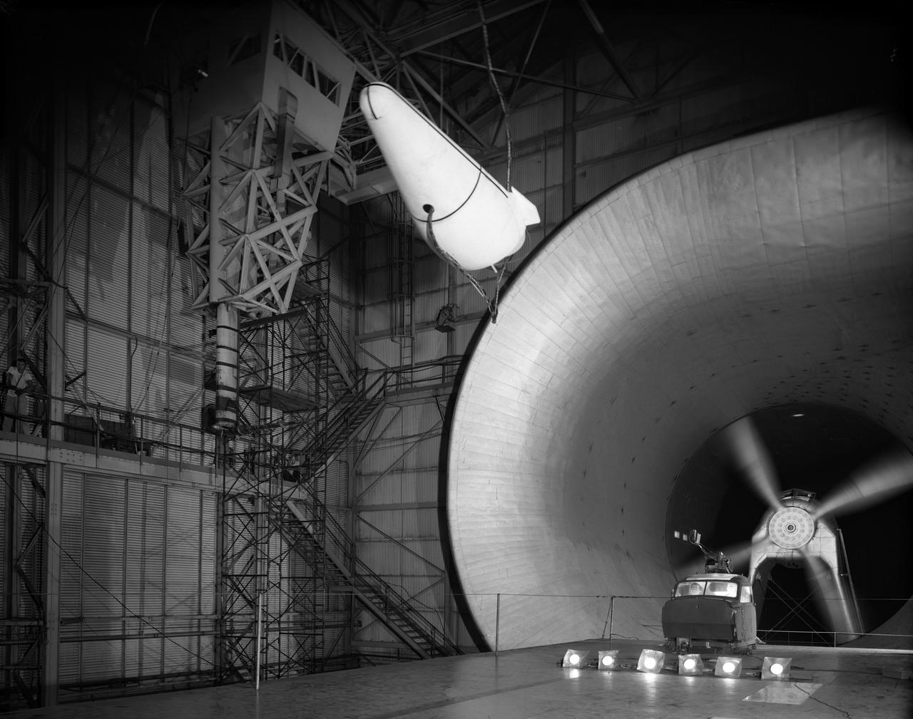
Re-entry vehicle on Full Scale Tunnel (FST)
M-2 Lifting body 40x80ft Full Scale Wind Tunnel
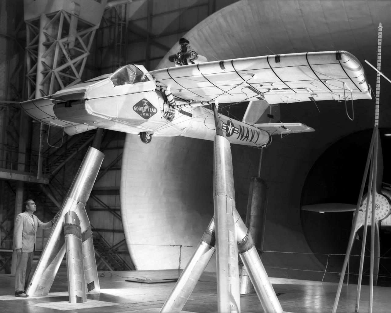
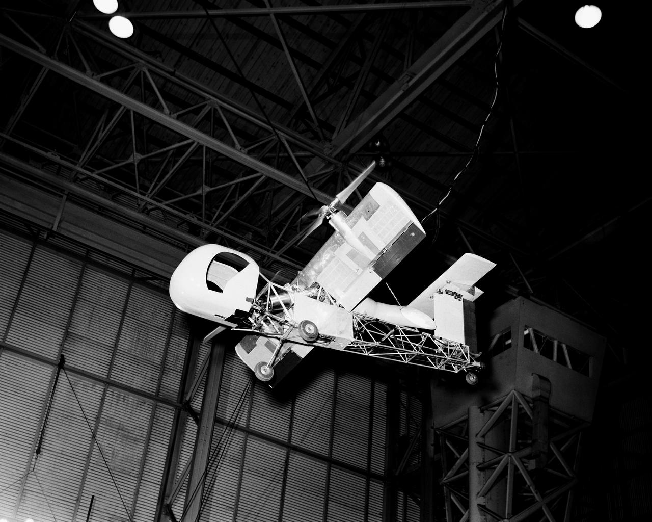
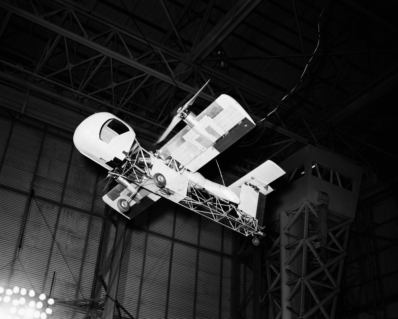
Various views of the Goodyear Inflate-A-Plane mounted in Full Scale Tunnel.
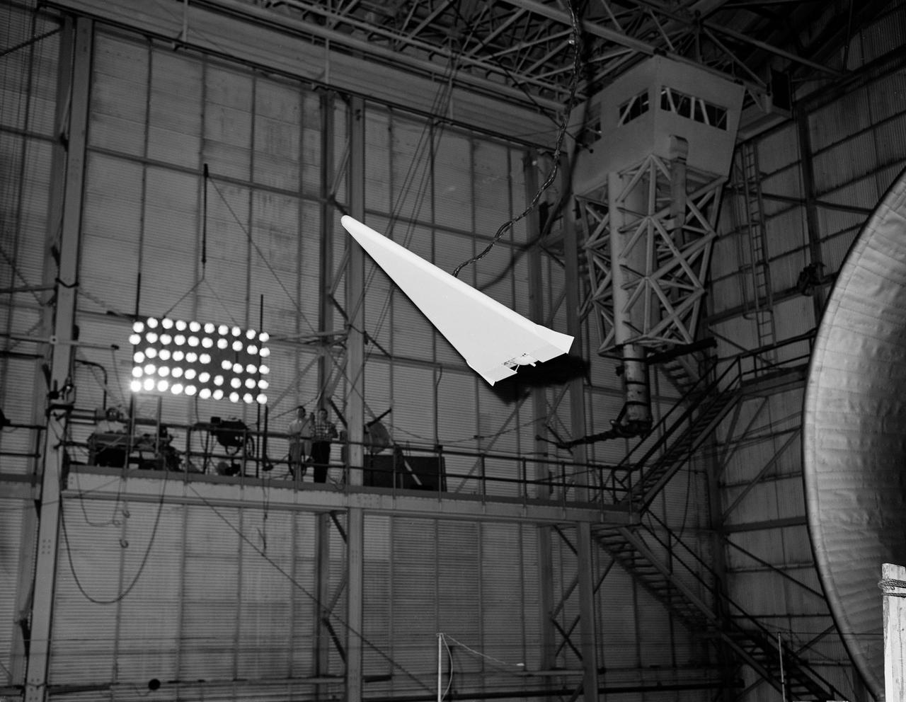
Flat Delta Model Flying in Full Scale Tunnel (FST) (Boiseau)
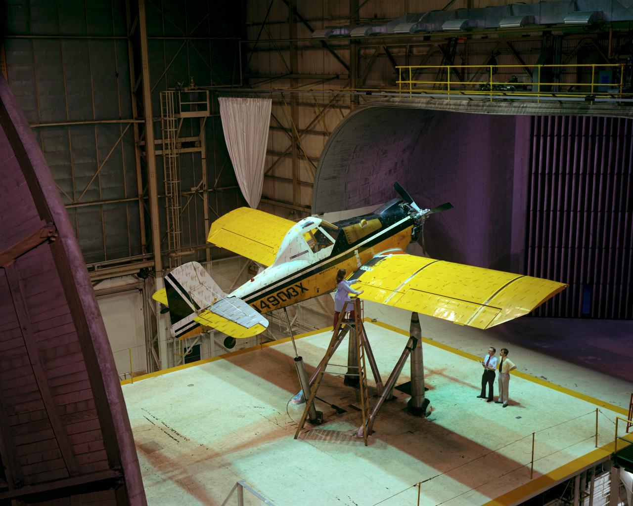
Agriculture aircraft in Full Scale Tunnel (FST). -- Photographed on: 05/19/78.
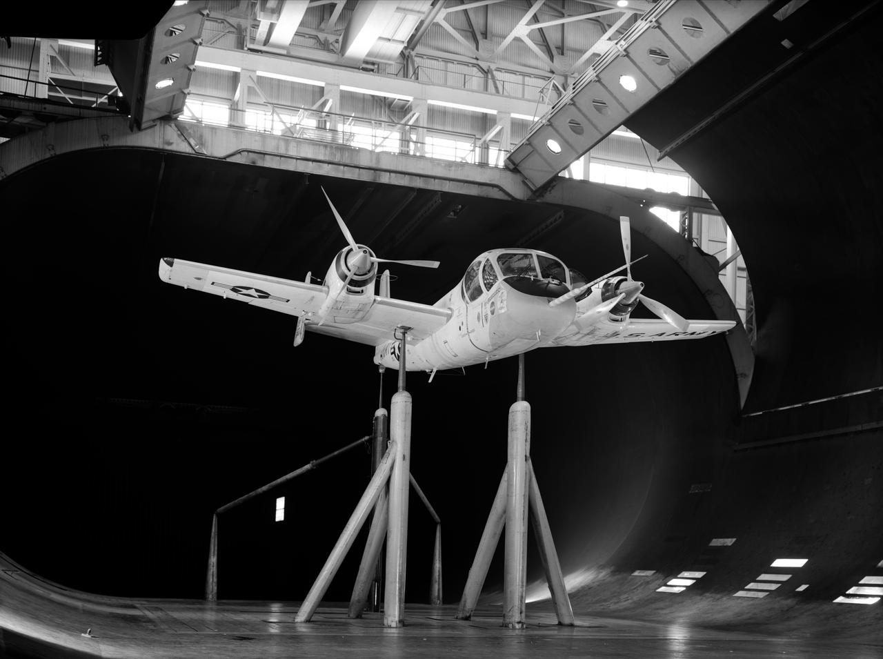
Drag studies for Full Scale wind tunnel test of Grumman YAO-1 airplane, 3/4 front view with propellers on
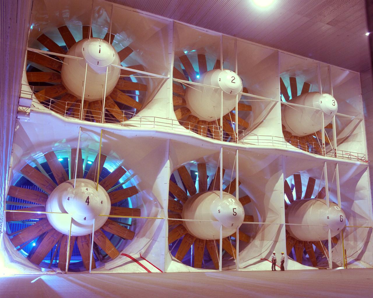
Ames National Full-Scale Aerodynamic Complex - NFAC; 80x120ft Wind Tunnel, drive fans during reconstruction process
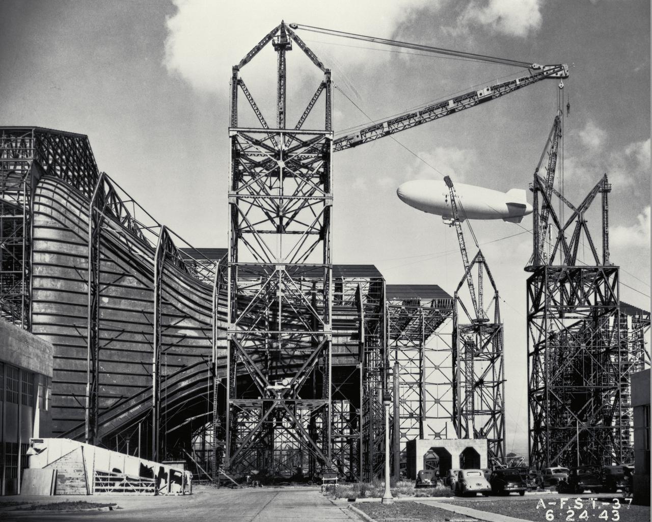
Construction of the Ames Full-Scale 40x80ft Wind tunnel. - side view of entrance cone, blimp in background
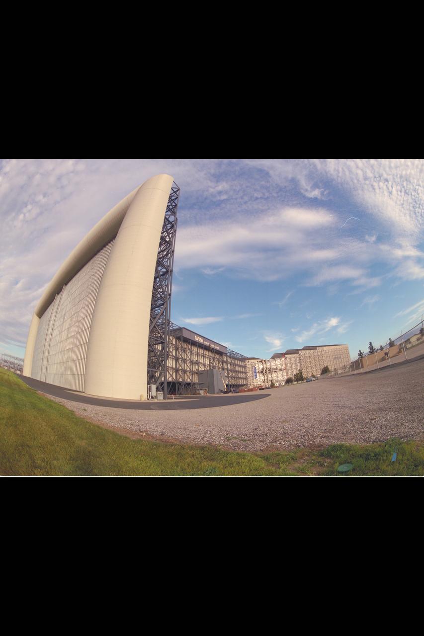
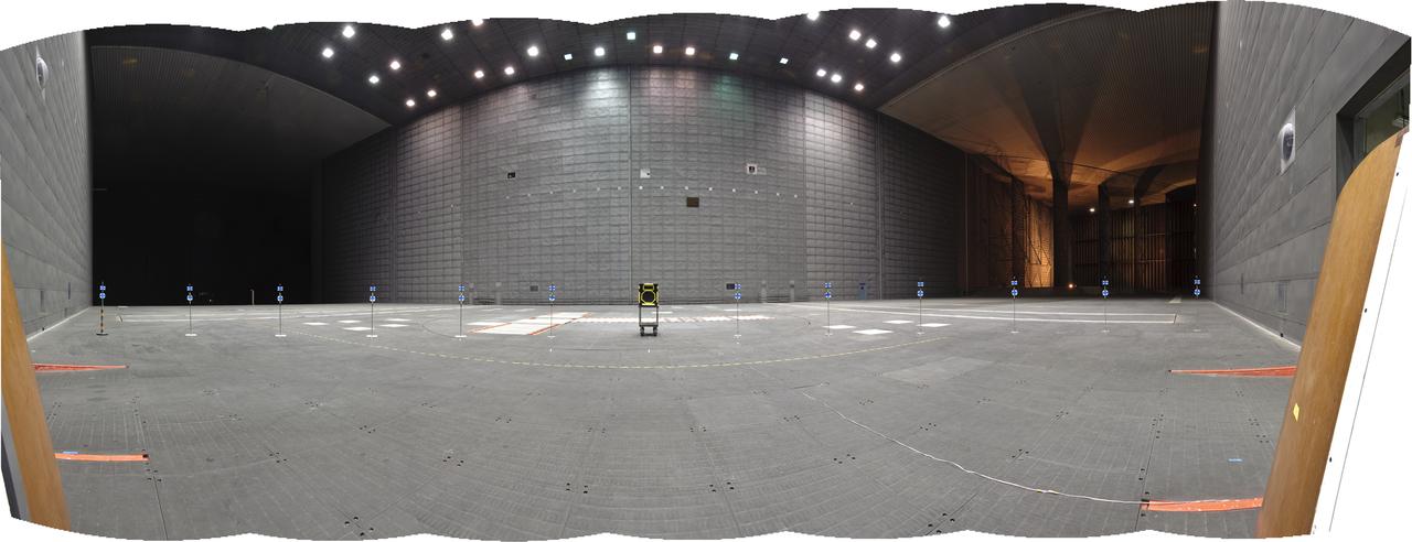
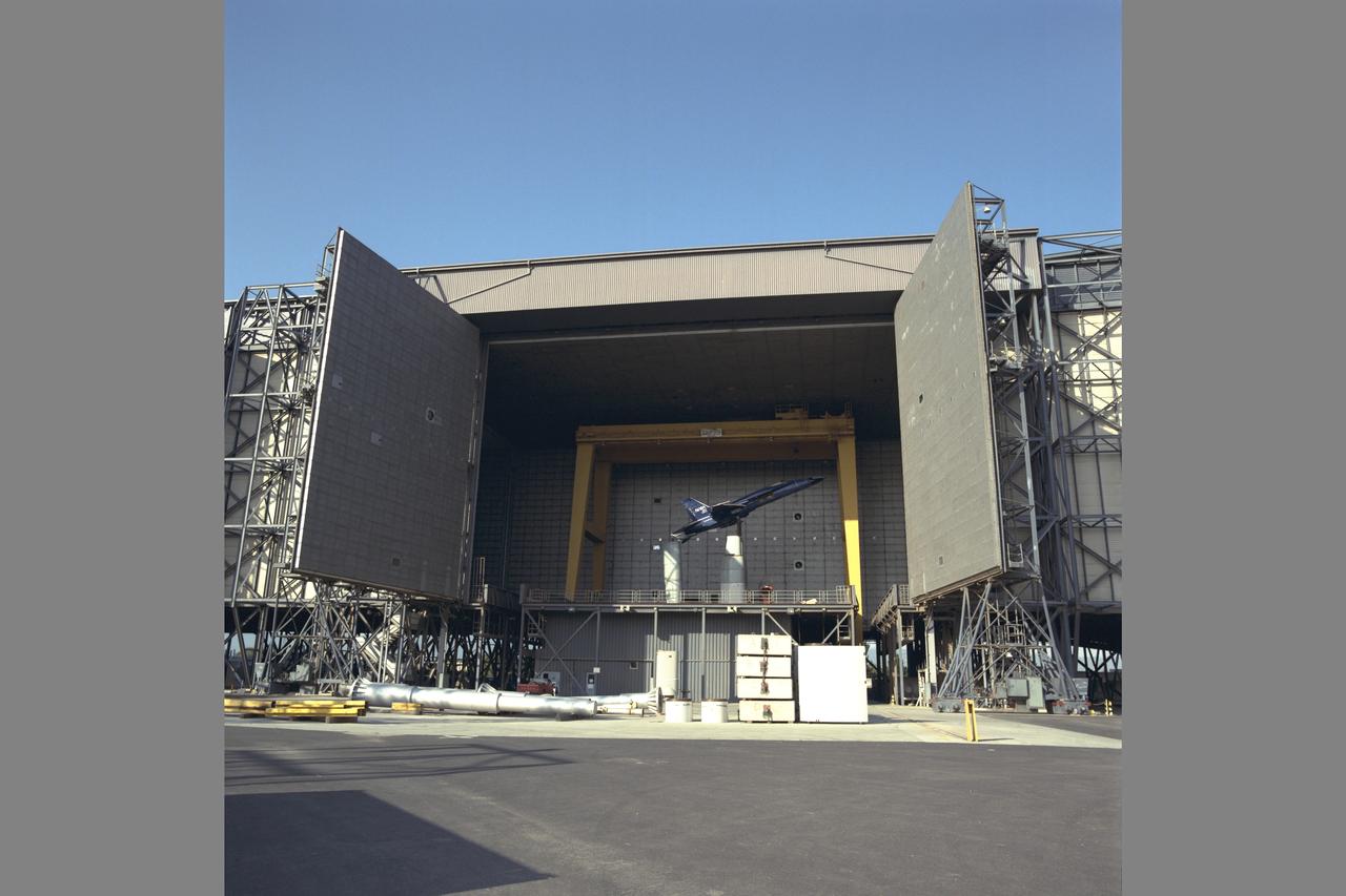
National Full-Scale Aerodynamic Complex (NFAC) 40x80x120ft wind tunnel fisheye view
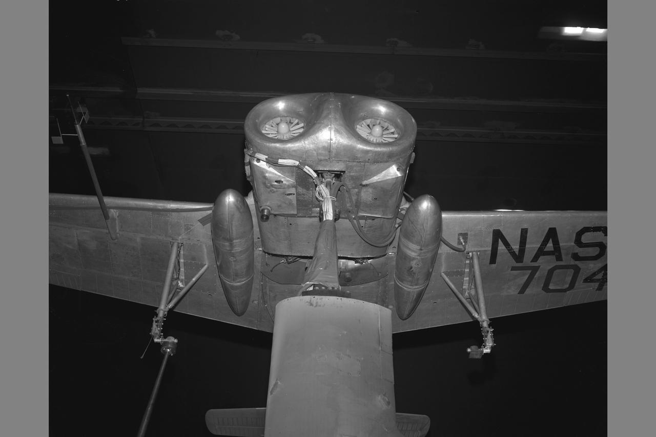
X-14 NASA 704 Full Scale Airplane tests in 40x80ft. Wind Tunnel (NORMAL MOUNTING) jet inlets
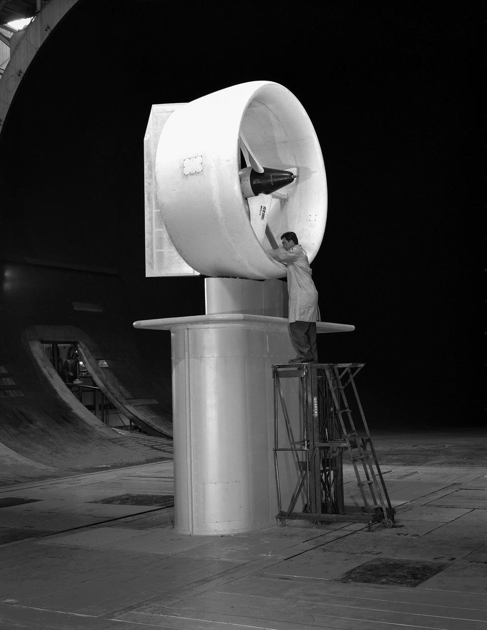
Bell X-22A full scale, Model-C ducted fan with semi-span mount. Duct at 90 degrees with Chuck Greco.
National Full Scale Aerodynamic Complex (NFAC) located at the NASA Ames Research Center 80x20ft. wind tunnel microphone array background noise test
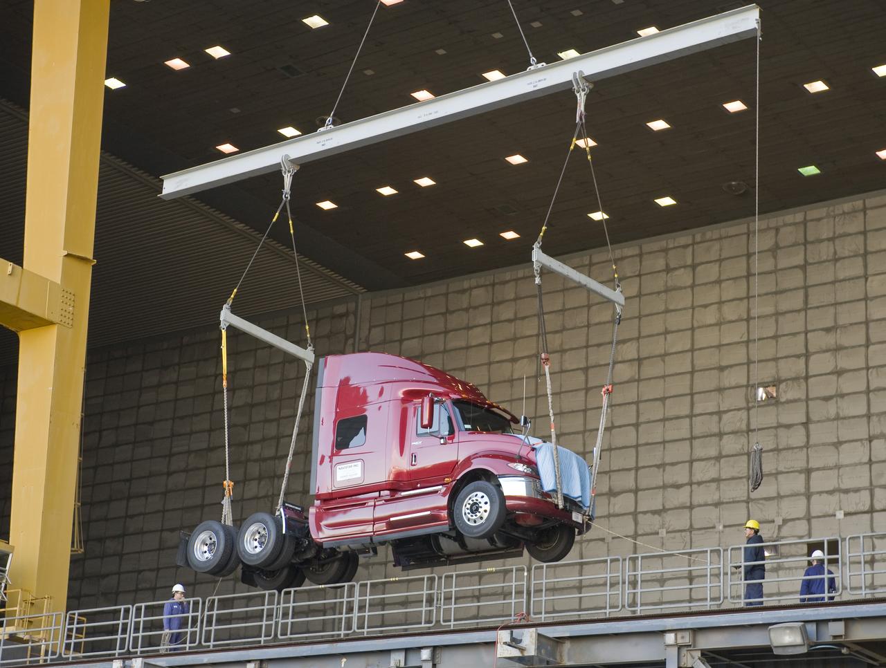
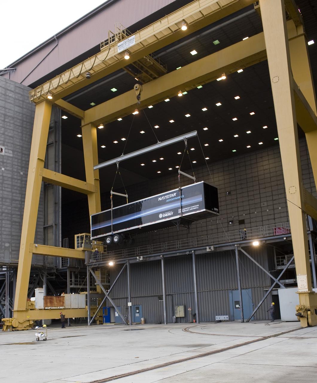
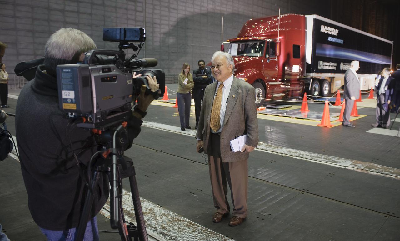
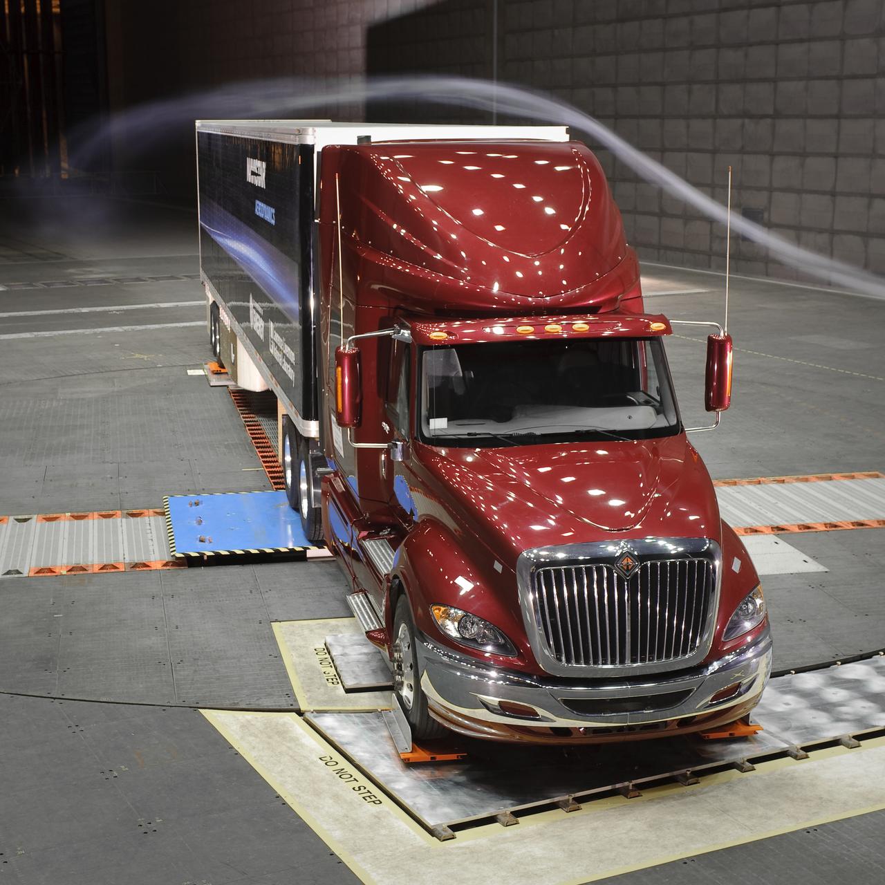
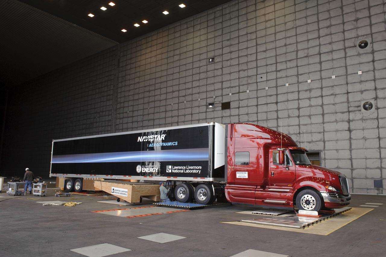
Lawrence Livermore National Labs (LLNL), Navistar and the Department of Energy conduct tests in the NASA Ames National Full-scale Aerodynamic Complex 80x120_foot wind tunnel. The LLNL project is aimed at aerodynamic truck and trailer devices that can reduce fuel consumption at highway speed by 10 percent. Cab being lifted into the tunnel.
The 10- by 10-Foot Supersonic Wind Tunnel (10×10) is the largest and fastest wind tunnel facility at NASA’s Glenn Research Center and is specifically designed to test supersonic propulsion components from inlets and nozzles to full-scale jet and rocket engines.
Lawrence Livermore National Labs (LLNL), Navistar and the Department of Energy conduct tests in the NASA Ames National Full-scale Aerodynamic Complex 80x120_foot wind tunnel. The LLNL project is aimed at aerodynamic truck and trailer devices that can reduce fuel consumption at highway speed by 10 percent. Trailer being lifted into the tunnel.
Looking South from inside the diffuser of the 40x80 foot wind tunnel at NACA's Ames Research Center. Construction began in late 1941, the mammoth construction task sorely taxing the resources of the new center. Two and a half years later, in dune 1944, the 40 x 80-foot full-scale tunnel went into operation.
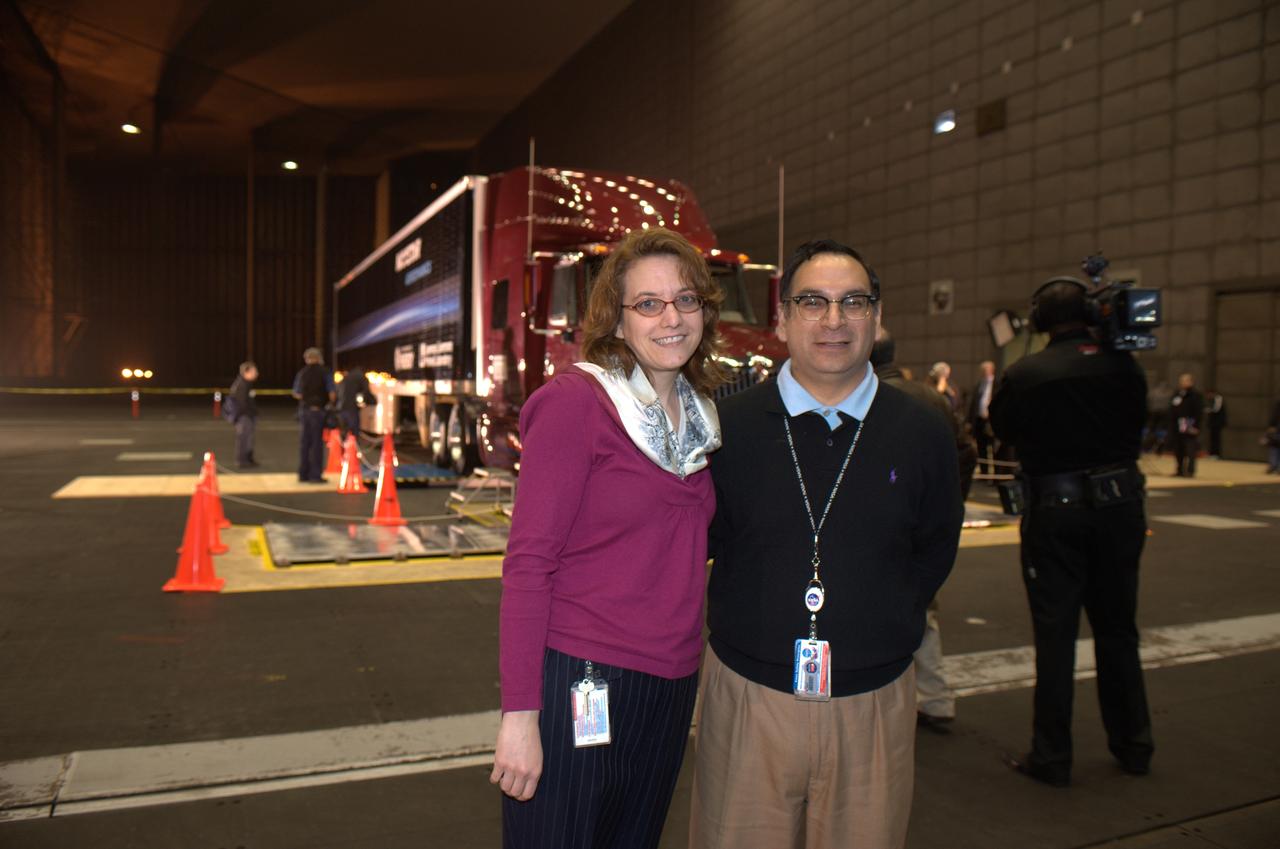
Lawrence Livermore National Laboratories media Day for their LLNL project aimed at aerodynamic truck and trailer devices. Tests are being preformed in the Ames Full-Scale Aerodynamic Complex 80x120 foot wind tunnel. Gabriel and Sharon Lozano.
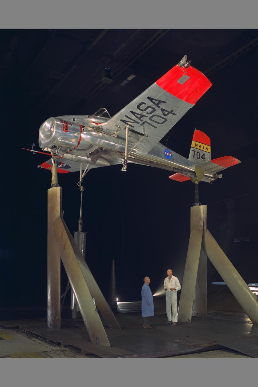
X-14 NASA 704 Full Scale Airplane tests in 40x80ft. Subsonic Wind Tunnel (NORMAL MOUNTING) with Sy Sewell, NASA (left) and Ed Varette, Army (right)
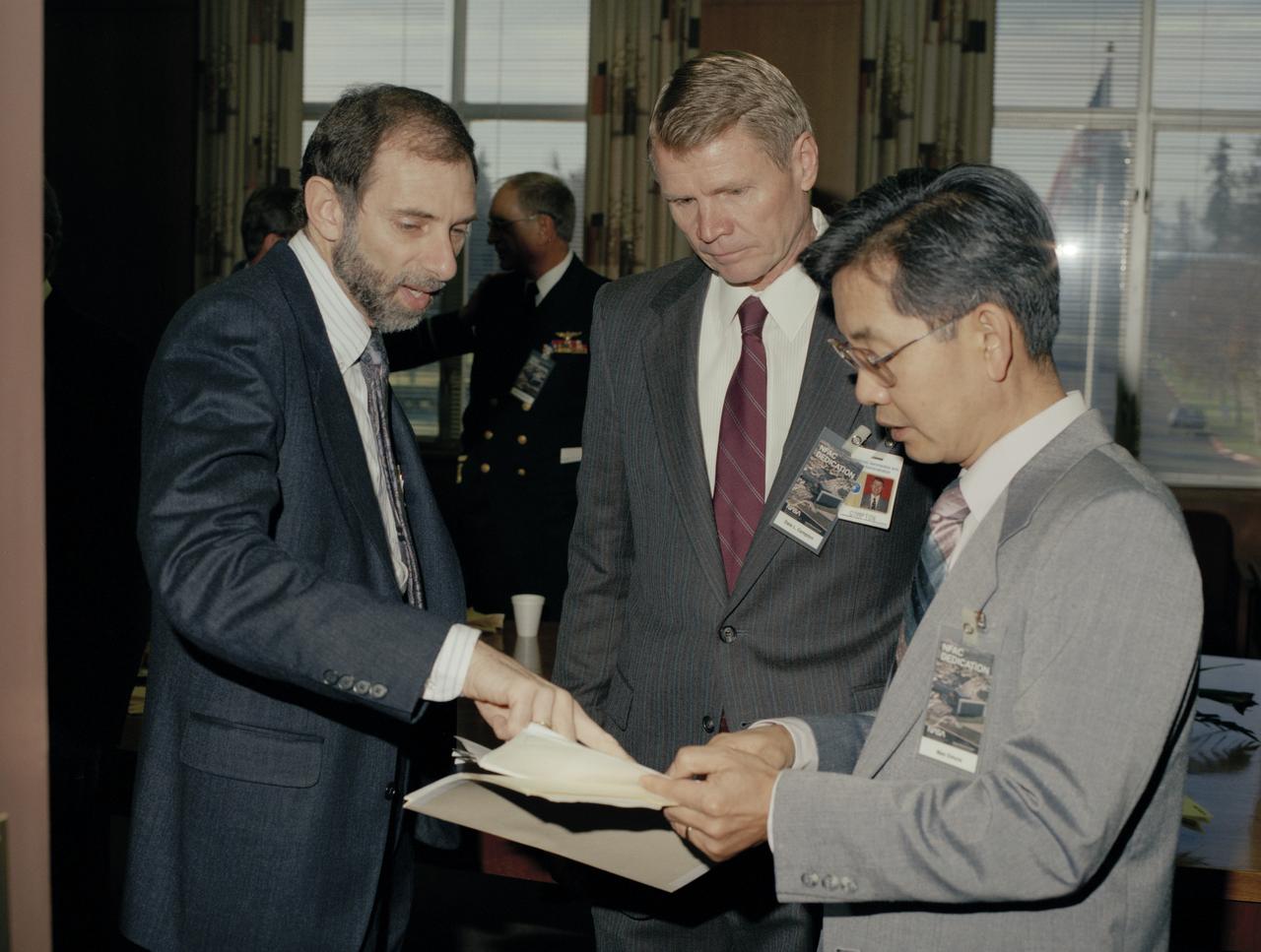
NASA Ames National Full-Scale Aerodynamic Facility (40x80x120ft Wind Tunnels & Outdoor Aerodynamic Research Facility - OARF) 1987 NFAC dedication - middle Dale Compton, on right Mas Omura
F-18 being installed in the NASA Ames Full-scale Aerodynamic Complex (NFAC) 80x120_foot wind tunnel test section for High Alpha Test-823 Phase II
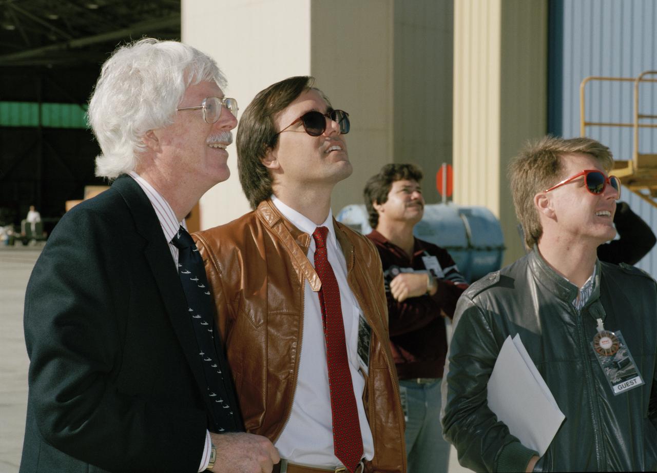
NASA Ames National Full-Scale Aerodynamic Facility (40x80x120ft Wind Tunnels & Outdoor Aerodynamic Research Facility - OARF) 1987 NFAC dedication - Kip Edenborough at airshow
Lawrence Livermore National Laboratories media Day for their LLNL project aimed at aerodynamic truck and trailer devices. Tests are being preformed in the Ames Full-Scale Aerodynamic Complex 80x120 foot wind tunnel.
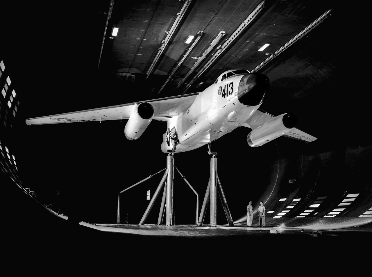
The Ames 40 by 80 foot full scale wind tunnel could just accommodate the 72.5 foot wingspan of the Douglas A3D Sky warrior. Date unknown. -: Unknown film. SBA settings neutral SBA on, color SBA on
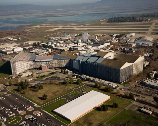
N-221 NASA Ames Research Center National Full-Scale Aerodynamic Complex NFAC (40x80x120) foot wind tunnel aerial with new Army Admin. building in foreground
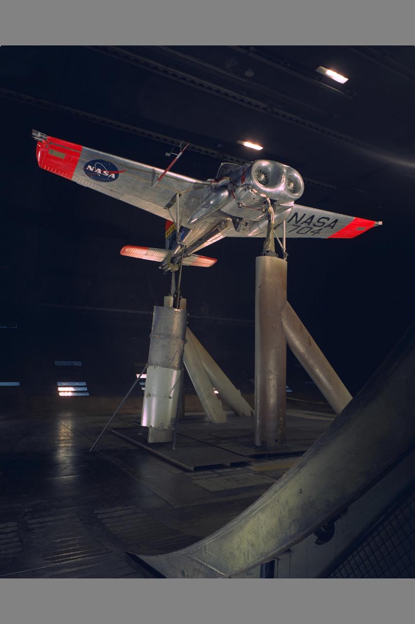
X-14 NASA 704 Full Scale Airplane tests in 40x80ft. Wind Tunnel (NORMAL MOUNTING) with Sy Sewell, NASA (left) and Ed Varette, Army (right)
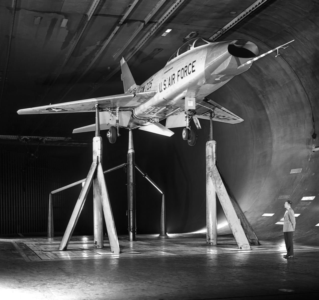
North American F-100-F airplane, equipped with thrust reversers, full scale wind tunnel test. 3/4 front view of F-100-F airplane with North American Aviation thrust reverser. On standard 40x80 struts landing gear down. Mark Kelly, branch chief in photo.
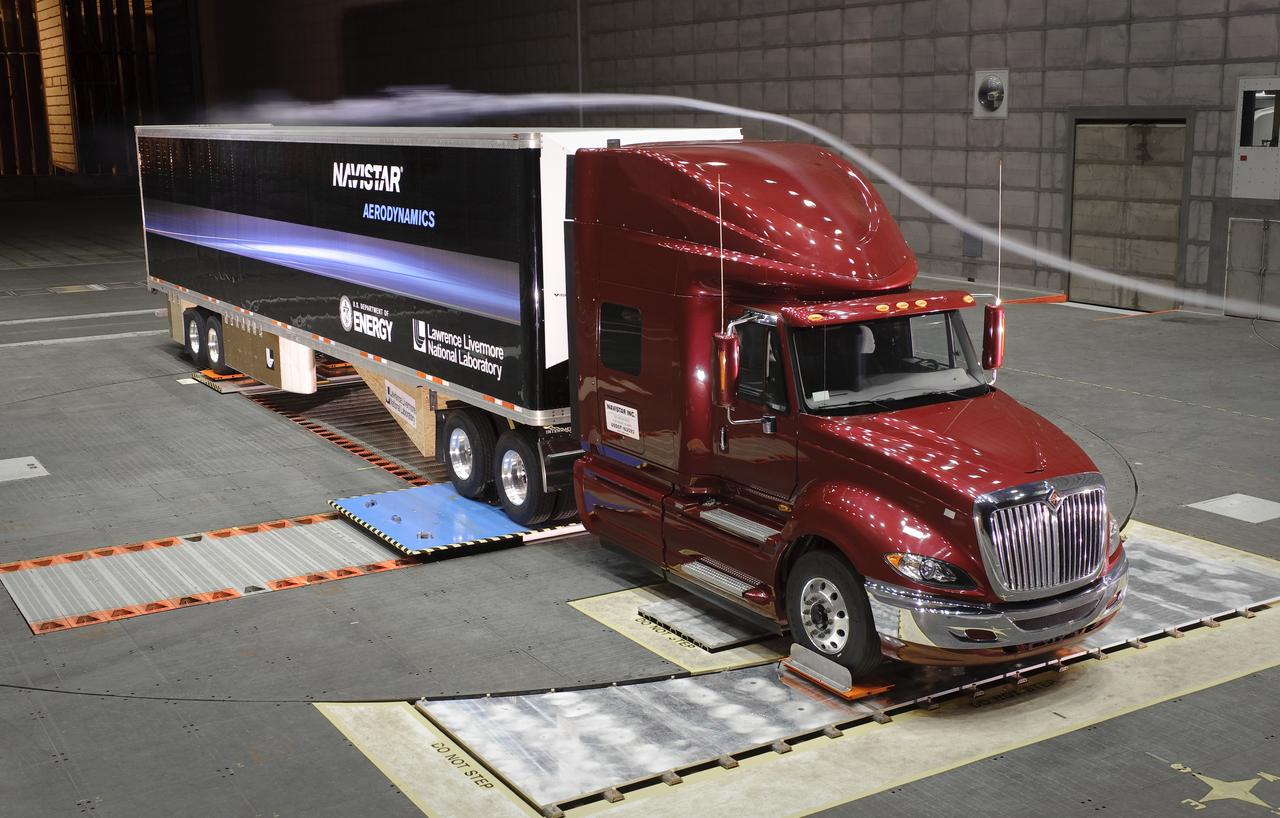
Lawrence Livermore National Labs (LLNL), Navistar and the Department of Energy conduct tests in the NASA Ames National Full-scale Aerodynamic Complex 80x120_foot wind tunnel. The LLNL project is aimed at aerodynamic truck and trailer devices that can reduce fuel consumption at highway speed by 10 percent. Smoke test demo.
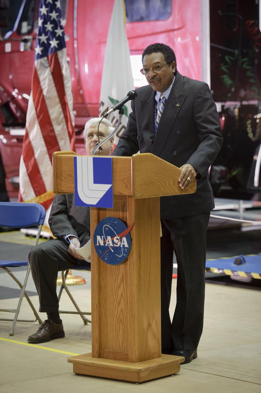
Lawrence Livermore National Laboratories media Day for their LLNL project aimed at aerodynamic truck and trailer devices. Tests are being preformed in the Ames Full-Scale Aerodynamic Complex 80x120 foot wind tunnel. Lewis Braxton III, Deputy Director Ames Research Center speaker.
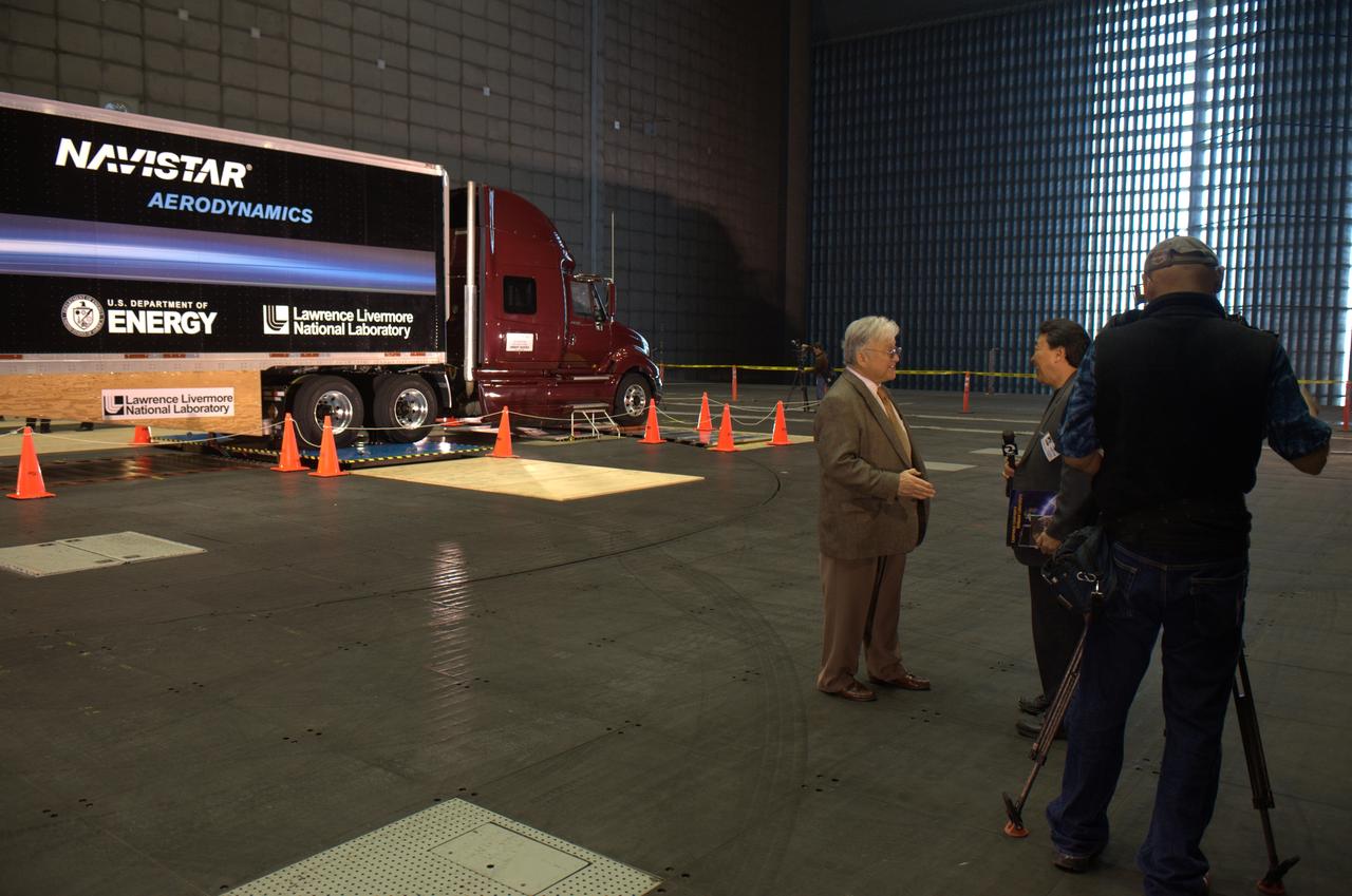
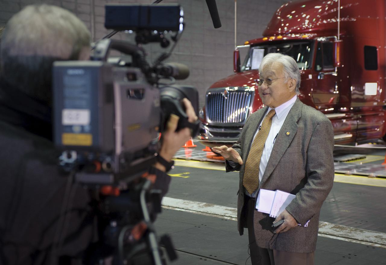
Lawrence Livermore National Laboratories media Day for their LLNL project aimed at aerodynamic truck and trailer devices. Tests are being preformed in the Ames Full-Scale Aerodynamic Complex 80x120 foot wind tunnel. Mike Honda, U.S Congressman from California's 15th District
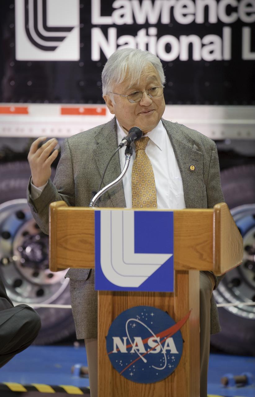
Lawrence Livermore National Laboratories media Day for their LLNL project aimed at aerodynamic truck and trailer devices. Tests are being preformed in the Ames Full-Scale Aerodynamic Complex 80x120 foot wind tunnel. Mike Honda, U.S Congressman from California's 15th District
Lawrence Livermore National Labs (LLNL), Navistar and the Department of Energy conduct tests in the NASA Ames National Full-scale Aerodynamic Complex 80x120_foot wind tunnel. The LLNL project is aimed at aerodynamic truck and trailer devices that can reduce fuel consumption at highway speed by 10 percent. Smoke test demo.
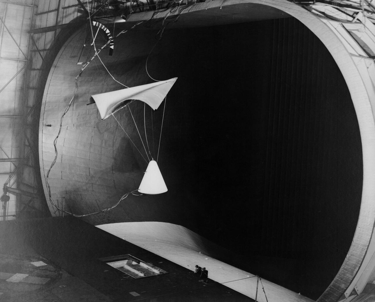
Image L61-4369 is available as an electronic file from the photo lab. See URL. -- Photographed on 06/30/1961. -- Test of parawing in Full Scale Wind Tunnel. -- Published in James R. Hansen, Spaceflight Revolution: NASA Langley Research Center From Sputnik to Apollo, (Washington: NASA, 1995), pp. 380-387.
Lawrence Livermore National Laboratories media Day for their LLNL project aimed at aerodynamic truck and trailer devices. Tests are being preformed in the Ames Full-Scale Aerodynamic Complex 80x120 foot wind tunnel. Mike Honda, U.S Congressman from California's 15th District
Lawrence Livermore National Labs (LLNL), Navistar and the Department of Energy conduct tests in the NASA Ames National Full-scale Aerodynamic Complex 80x120_foot wind tunnel. The LLNL project is aimed at aerodynamic truck and trailer devices that can reduce fuel consumption at highway speed by 10 percent. LLNL's test piece is being installed on truck.
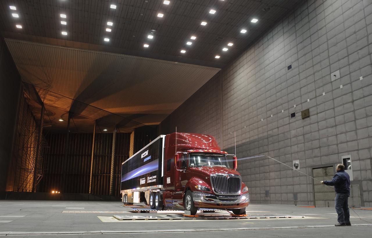
Lawrence Livermore National Labs (LLNL), Navistar and the Department of Energy conduct tests in the NASA Ames National Full-scale Aerodynamic Complex 80x120_foot wind tunnel. The LLNL project is aimed at aerodynamic truck and trailer devices that can reduce fuel consumption at highway speed by 10 percent. Smoke test demo with Ron Schoon, Navistar.

Lawrence Livermore National Labs (LLNL), Navistar and the Department of Energy conduct tests in the NASA Ames National Full-scale Aerodynamic Complex 80x120_foot wind tunnel. The LLNL project is aimed at aerodynamic truck and trailer devices that can reduce fuel consumption at highway speed by 10 percent. Smoke test demo with Ron Schoon, Navistar.
The 8- by 6-Foot Supersonic Wind Tunnel at the National Advisory Committee for Aeronautics (NACA) Lewis Flight Propulsion Laboratory was the largest supersonic wind tunnel in the nation at the time and the only one able to test full-scale engines at supersonic speeds. The 8- by 6 was designed as a non-return and open-throat tunnel. A large compressor created the air flow at one end of the tunnel, squeezed the flow to increase its velocity just before the test section, then reduced the velocity, and expelled it into the atmosphere at the other end of the tunnel. This design worked well for initial aerodynamic testing, but the local community was literally rattled by the noise and vibrations when researchers began running engines in the test section in January 1950. The NACA’s most modern wind tunnel was referred to as “an 87,000-horsepower bugle aimed at the heart of Cleveland.” NACA Lewis responded to the complaints by adding an acoustic housing at the end of the tunnel to dampen the noise. The structure included resonator chambers and a reinforced concrete muffler structure. Modifications continued over the years. A return leg was added, and a second test section, 9 -by 15-foot, was incorporated in the return leg in the 1960s. Since its initial operation in 1948, the 8- by 6-foot tunnel has been aggressively used to support the nation's aeronautics and space programs for the military, industry, and academia.
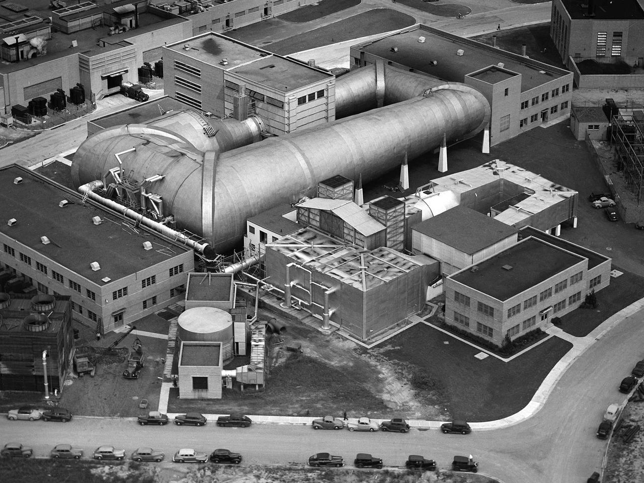
This aerial photograph shows the entire original wind tunnel complex at the National Advisory Committee for Aeronautics (NACA) Aircraft Engine Research Laboratory. The large Altitude Wind Tunnel (AWT) at the center of the photograph dominates the area. The Icing Research Tunnel to the right was incorporated into the lab’s design to take advantage of the AWT’s powerful infrastructure. The laboratory’s first supersonic wind tunnel was added to this complex just prior to this September 1945 photograph. The AWT was the nation’s only wind tunnel capable of studying full-scale engines in simulated flight conditions. The AWT’s test section and control room were within the two-story building near the top of the photograph. The exhauster equipment used to thin the airflow and the drive motor for the fan were in the building to the right of the tunnel. The unique refrigeration equipment was housed in the structure to the left of the tunnel. The Icing Research Tunnel was an atmospheric tunnel that used the AWT’s refrigeration equipment to simulate freezing rain inside its test section. A spray bar system inside the tunnel was originally used to create the droplets. The 18- by 18-inch supersonic wind tunnel was built in the summer of 1945 to take advantage of the AWT’s powerful exhaust system. It was the lab’s first supersonic tunnel and could reach Mach 1.91. Eventually the building would house three small supersonic tunnels, referred to as the “stack tunnels” because of the vertical alignment. The two other tunnels were added to this structure in 1949 and 1951.
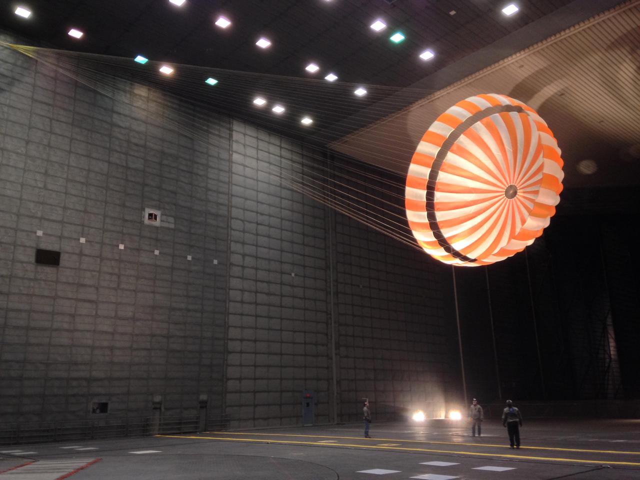
This parachute testing for NASA's InSight mission to Mars was conducted inside the world's largest wind tunnel, at NASA Ames Research Center, Moffett Field, California, in February 2015. The wind tunnel is 80 feet (24 meters) tall and 120 feet (37 meters) wide. It is part of the National Full-Scale Aerodynamics Complex, operated by the Arnold Engineering Development Center of the U.S. Air Force. Note: After thorough examination, NASA managers have decided to suspend the planned March 2016 launch of the Interior Exploration using Seismic Investigations Geodesy and Heat Transport (InSight) mission. The decision follows unsuccessful attempts to repair a leak in a section of the prime instrument in the science payload. http://photojournal.jpl.nasa.gov/catalog/PIA19405
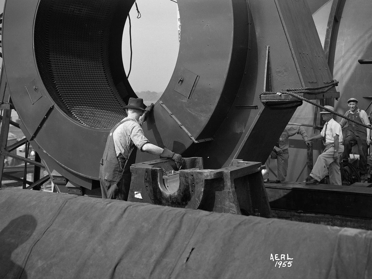
Construction workers install the drive motor for the Altitude Wind Tunnel (AWT) in the Exhauster Building at the National Advisory Committee for Aeronautics (NACA) Aircraft Engine Research Laboratory. The AWT was capable of operating full-scale engines in air density, speed, and temperature similar to that found at high altitudes. The tunnel could produce wind speeds up to 500 miles per hour through a 20-foot-diameter test section at the standard operating altitude of 30,000 feet. The airflow was created by a large wooden fan near the tunnel’s southeast corner. This photograph shows the installation of the 18,000-horsepower drive motor inside the adjoining Exhauster Building in July 1943. The General Electric motor, whose support frame is seen in this photograph, connected to a drive shaft that extended from the building, through the tunnel shell, and into a 12-bladed, 31-foot-diameter spruce wood fan. Flexible couplings on the shaft allowed for the movement of the shell. The corner of the Exhauster Building was built around the motor after its installation. The General Electric induction motor could produce 10 to 410 revolutions per minute and create wind speeds up to 500 miles per hour, or Mach 0.63, at 30,000 feet. The AWT became operational in January 1944 and tested piston, turbojet and ramjet engines for nearly 20 years.
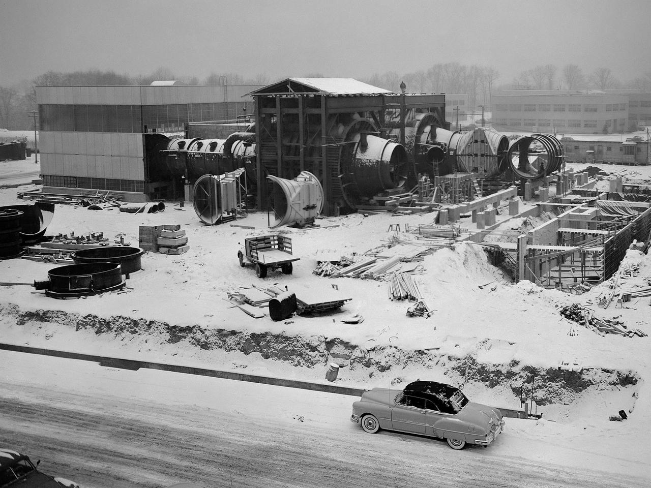
Construction of the Propulsion Systems Laboratory No. 1 and 2 at the National Advisory Committee for Aeronautics (NACA) Lewis Flight Propulsion Laboratory. When it began operation in late 1952, the Propulsion Systems Laboratory was the NACA’s most powerful facility for testing full-scale engines at simulated flight altitudes. The facility contained two altitude simulating test chambers which were a technological combination of the static sea-level test stands and the complex Altitude Wind Tunnel, which recreated actual flight conditions on a larger scale. NACA Lewis began designing the new facility in 1947 as part of a comprehensive plan to improve the altitude testing capabilities across the lab. The exhaust, refrigeration, and combustion air systems from all the major test facilities were linked. In this way, different facilities could be used to complement the capabilities of one another. Propulsion Systems Laboratory construction began in late summer 1949 with the installation of an overhead exhaust pipe connecting the facility to the Altitude Wind Tunnel and Engine Research Building. The large test section pieces arriving in early 1951, when this photograph was taken. The two primary coolers for the altitude exhaust are in place within the framework near the center of the photograph.
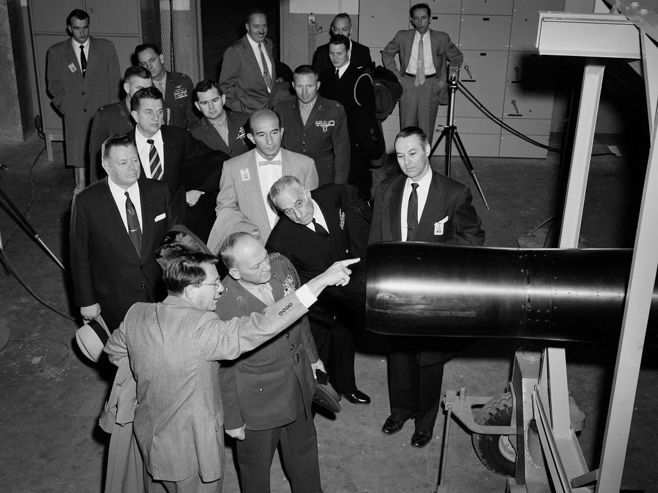
Abe Silverstein, Associate Director of the National Advisory Committee for Aeronautics (NACA) Lewis Flight Propulsion Laboratory, provides a personal tour of the new 10- by 10-Foot Supersonic Wind Tunnel for US Senator George Bender (hat in hand) and General Lemuel Shepherd. Shepherd was Commandant of the Marine Corps and had served in World War I, World War II, and the Korean War. The general was accompanied by Admiral Herbert Leary, in dark uniform. Bender was a Republican Senator from Ohio. Behind Bender is President of the Cleveland Chamber of Commerce Curtis Smith. NACA Lewis managers Eugene Manganiello and Wilson Hunter assist with the tour. Abe Silverstein oversaw all research at the laboratory. Upon taking his post in 1952 he reorganized the research staff and began shifting the focus away from airbreathing aircraft engines to new fields such as high energy fuels, electric propulsion, and nuclear power and propulsion. He was an early advocate of the NACA’s involvement in the space program and crucial to the founding of National Aeronautics and Space Administration in 1958. Silverstein began his career helping design and conduct research in the Full Scale Tunnel in 1929 at the Langley Memorial Aeronautical Laboratory. Silverstein advocated a series of increasingly large supersonic wind tunnels after the war, culminating in the 10- by 10.
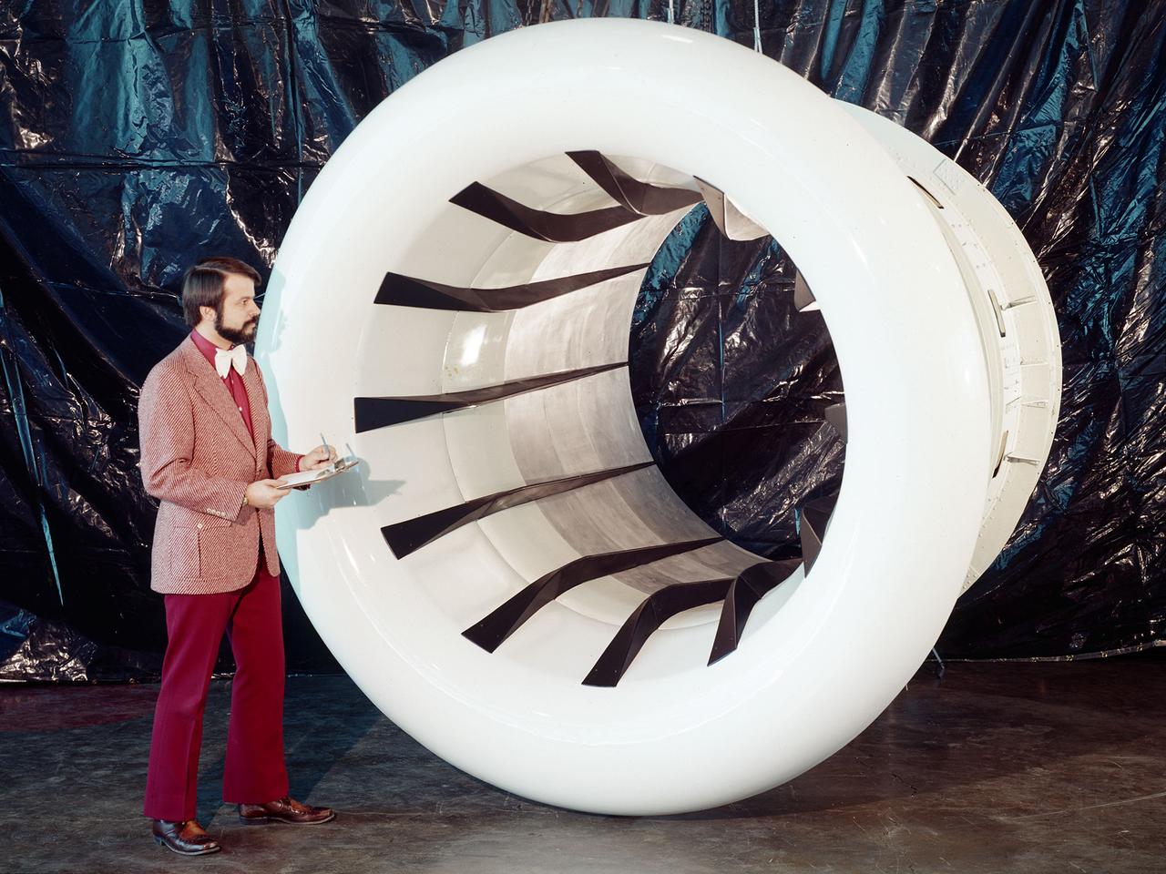
Brent Miller, of the V/STOL and Noise Division at the National Aeronautics and Space Administration (NASA) Lewis Research Center, poses with a sonic inlet for the NASA Quiet Engine Program. NASA Lewis had first investigated methods for reducing aircraft engine noise in the mid-1950s. Those efforts were resurrected and expanded in the late 1960s. The researchers found that the use of a sonic, or high-throat-Mach-number, inlet was effective at reducing the noise from the engine inlet. The device accelerated the inlet air to near-sonic speeds which kept the forward moving sound waves away from the inlet. The device also deflected the sound waves into the wall to further reduce the noise. NASA Lewis researchers tested models of the sonic inlet in their 9- by 15-Foot Low Speed Wind Tunnel. They found that the general level of aerodynamic performance was good. The tests during simulated takeoff and landing conditions demonstrated the sonic inlet’s ability to provide good aerodynamic and acoustic performance The researchers then successfully tested two full-scale sonic inlet designs, one from Pratt and Whitney and one from General Electric, with fans. A full-scale engine was installed on a thrust stand to determine the sonic inlet’s effect on the engine’s performance. The amount of noise reduction increased as the inlet flow velocity increased, but the full-scale tests did not produce as great a decrease in noise as the earlier small-scale tests.
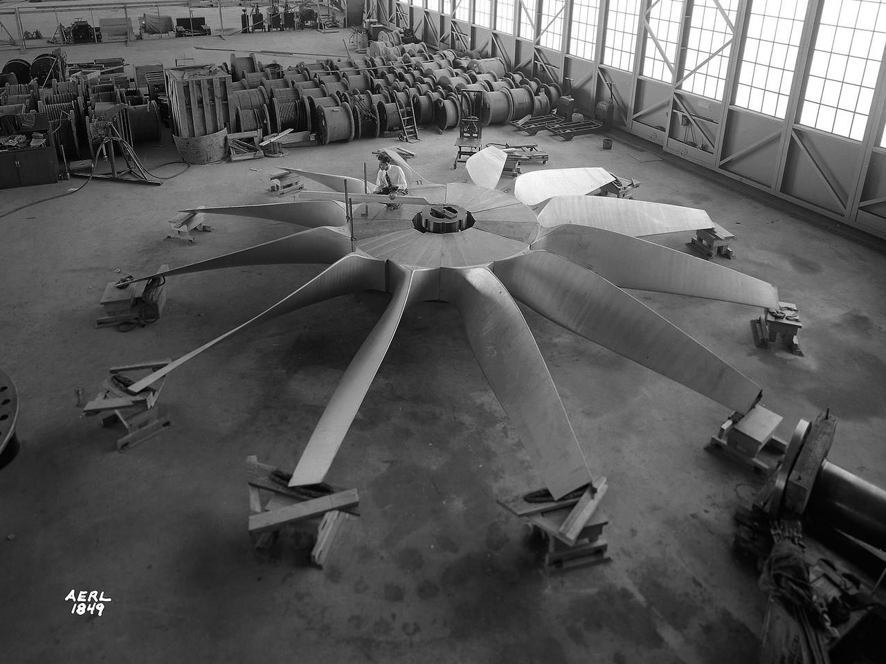
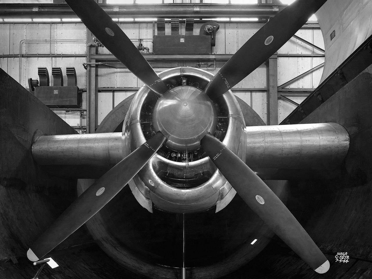
National Advisory Committee for Aeronautics (NACA) engineers assembled the Altitude Wind Tunnel’s (AWT) large wooden drive fan inside the hangar at the Aircraft Engine Research Laboratory. When it was built at the in the early 1940s the AWT was among the most complex test facilities ever designed. It was the first wind tunnel capable of operating full-scale engines under realistic flight conditions. This simulation included the reduction of air temperature, a decrease in air pressure, and the creation of an airstream velocity of up to 500 miles per hour. The AWT was constructed in 1942 and 1943. This photograph shows NACA engineers Lou Hermann and Jack Aust assembling the tunnel’s drive fan inside the hangar. The 12-bladed, 31-foot-diameter spruce wood fan would soon be installed inside the wind tunnel to create the high-speed airflow. This massive propeller was designed and constructed by the engine lab's design team at Langley Field. John Breisch, a Langley technician with several years of wind tunnel installation experience, arrived in Cleveland at the time of this photograph to supervise the fan assembly inside the hangar. He would return several weeks later to oversee the actual installation in the tunnel. The fan was driven at 410 revolutions per minute by an 18,000-horsepower General Electric induction motor that was located in the rear corner of the Exhauster Building. An extension shaft connected the motor to the fan. A bronze screen protected the fan against damage from failed engine parts sailing through the tunnel. Despite this screen the blades did become worn or cracked over time and had to be replaced. An entire new fan was installed in 1951.
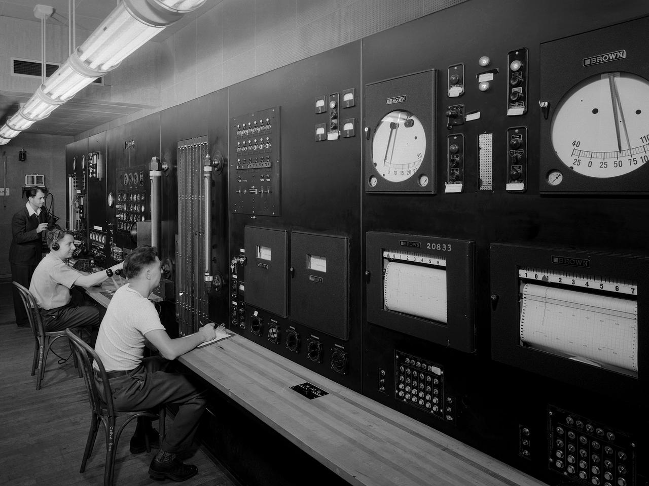
Operators in the control room for the Altitude Wind Tunnel at the National Advisory Committee for Aeronautics (NACA) Aircraft Engine Research Laboratory remotely operate a Wright R–3350 engine in the tunnel’s test section. Four of the engines were used to power the B–29 Superfortress, a critical weapon in the Pacific theater during World War II. The wind tunnel, which had been in operation for approximately six months, was the nation’s only wind tunnel capable of testing full-scale engines in simulated altitude conditions. The soundproof control room was used to operate the wind tunnel and control the engine being run in the test section. The operators worked with assistants in the adjacent Exhauster Building and Refrigeration Building to manage the large altitude simulation systems. The operator at the center console controlled the tunnel’s drive fan and operated the engine in the test section. Two sets of pneumatic levers near his right forearm controlled engine fuel flow, speed, and cooling. Panels on the opposite wall, out of view to the left, were used to manage the combustion air, refrigeration, and exhauster systems. The control panel also displayed the master air speed, altitude, and temperature gauges, as well as a plethora of pressure, temperature, and airflow readings from different locations on the engine. The operator to the right monitored the manometer tubes to determine the pressure levels. Despite just being a few feet away from the roaring engine, the control room remained quiet during the tests.
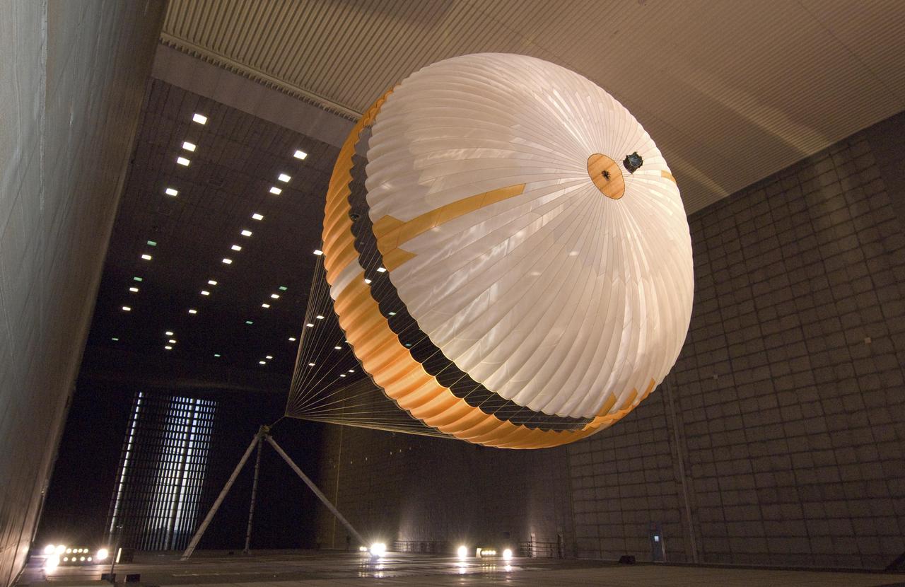
The parachute for NASA next mission to Mars passed flight-qualification testing in March and April 2009 inside the world largest wind tunnel, at NASA Ames Research Center, Moffett Field, Calif. NASA's Mars Science Laboratory mission, to be launched in 2011 and land on Mars in 2012, will use the largest parachute ever built to fly on an extraterrestrial mission. This image shows a duplicate qualification-test parachute inflated in an 80-mile-per-hour (36-meter-per-second) wind inside the test facility. The parachute uses a configuration called disk-gap-band. It has 80 suspension lines, measures more than 50 meters (165 feet) in length, and opens to a diameter of nearly 16 meters (51 feet). Most of the orange and white fabric is nylon, though a small disk of heavier polyester is used near the vent in the apex of the canopy due to higher stresses there. It is designed to survive deployment at Mach 2.2 in the Martian atmosphere, where it will generate up to 65,000 pounds of drag force. The wind tunnel is 24 meters (80 feet) tall and 37 meters (120 feet) wide, big enough to house a Boeing 737. It is part of the National Full-Scale Aerodynamics Complex, operated by the Arnold Engineering Development Center of the U.S. Air Force. http://photojournal.jpl.nasa.gov/catalog/PIA11995
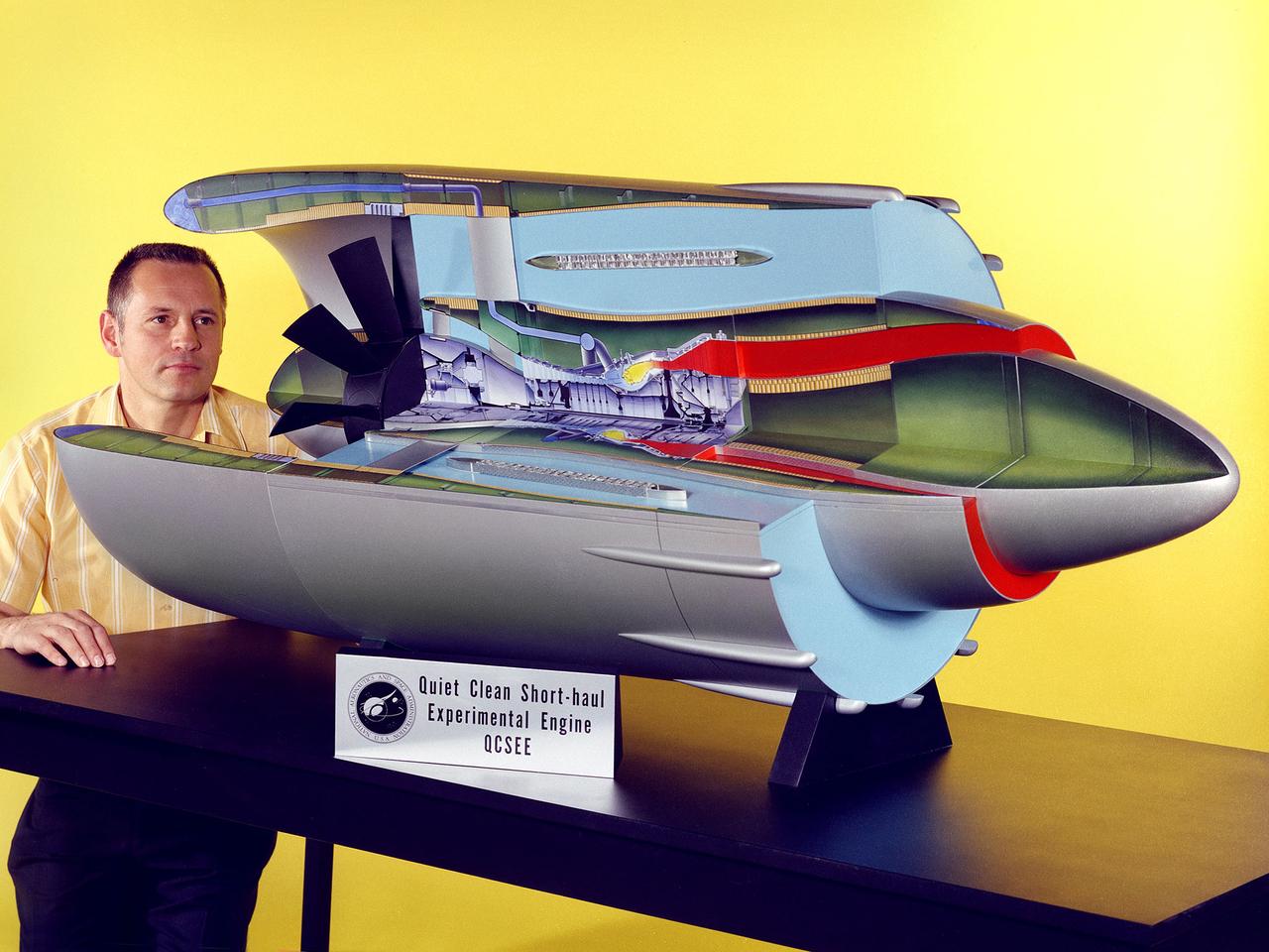
Program manager Carl Ciepluch poses with a model of the Quiet Clean Short Haul Experimental Engine (QCSEE) conceived by the National Aeronautics and Space Administration (NASA) Lewis Research Center. The QCSEE engine was designed to power future short-distance transport aircraft without generating significant levels of noise or pollution and without hindering performance. The engines were designed to be utilized on aircraft operating from small airports with short runways. Lewis researchers investigated two powered-lift designs and an array of new technologies to deal with the shorter runways. Lewis contracted General Electric to design the two QCSEE engines—one with over-the-wing power-lift and one with an under-the-wing design. A scale model of the over-the-wing engine was tested in the Full Scale Tunnel at the Langley Research Center in 1975 and 1976. Lewis researchers investigated both versions in a specially-designed test stand, the Engine Noise Test Facility, on the hangar apron. The QCSEE engines met the goals set out by the NASA researchers. The aircraft industry, however, never built the short-distance transport aircraft for which the engines were intended. Different technological elements of the engine, however, were applied to some future General Electric engines.
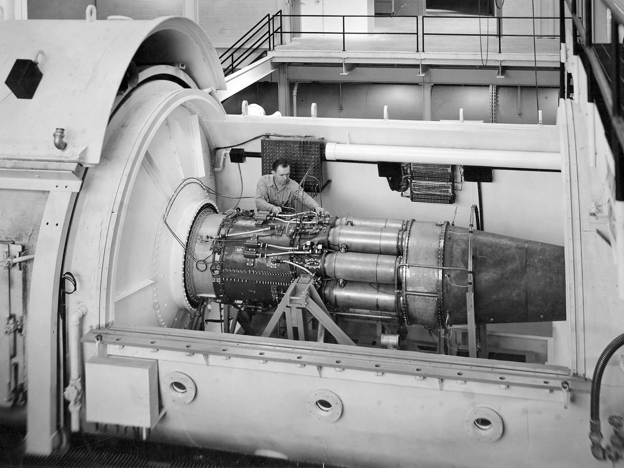
One of the two altitude simulating-test chambers in Engine Research Building at the National Advisory Committee for Aeronautics (NACA) Lewis Flight Propulsion Laboratory. The two chambers were collectively referred to as the Four Burner Area. NACA Lewis’ Altitude Wind Tunnel was the nation’s first major facility used for testing full-scale engines in conditions that realistically simulated actual flight. The wind tunnel was such a success in the mid-1940s that there was a backlog of engines waiting to be tested. The Four Burner chambers were quickly built in 1946 and 1947 to ease the Altitude Wind Tunnel’s congested schedule. The Four Burner Area was located in the southwest wing of the massive Engine Research Building, across the road from the Altitude Wind Tunnel. The two chambers were 10 feet in diameter and 60 feet long. The refrigeration equipment produced the temperatures and the exhauster equipment created the low pressures present at altitudes up to 60,000 feet. In 1947 the Rolls Royce Nene was the first engine tested in the new facility. The mechanic in this photograph is installing a General Electric J-35 engine. Over the next ten years, a variety of studies were conducted using the General Electric J-47 and Wright Aeronautical J-65 turbojets. The two test cells were occasionally used for rocket engines between 1957 and 1959, but other facilities were better suited to the rocket engine testing. The Four Burner Area was shutdown in 1959. After years of inactivity, the facility was removed from the Engine Research Building in late 1973 in order to create the High Temperature and Pressure Combustor Test Facility.
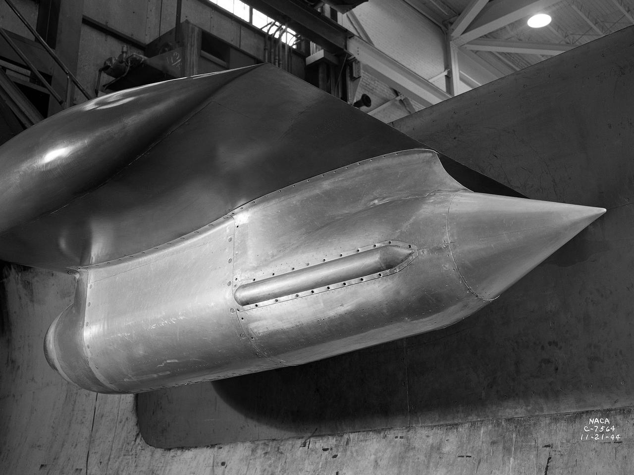
The Westinghouse 19XB turbojet seen from the side in the Altitude Wind Tunnel (AWT) test section at the National Advisory Committee for Aeronautics (NACA) Aircraft Engine Research Laboratory. Westinghouse started the development of a series of relatively small axial-flow turbojets for the Navy shortly after Pearl Harbor. In 1943 the 19A engine became both the first operational US-designed jet engine and the only U.S. turbojet incorporated into an aircraft during the war in Europe. In March 1943 Westinghouse agreed to create an improved six-stage 1400-pound thrust version, the 19B. The engine underwent its first test run a year later in March 1944. Almost immediately the navy agreed to Westinghouse’s proposal for the even larger 10-stage, 1600-pound-thrust 19XB prototype. By July 1944 the navy had contracted with the NACA for the testing of both engines in the AWT. The tunnel was the nation’s only facility for studying full-scale engines in simulated altitude conditions. The wind tunnel investigations, which began on September 9, 1944, revealed the superiority of the previously untested 19XB over the 19B. The 19B engines failed to restart consistently and suffered combustion blowouts above 17,000 feet. The 19XB, however, performed well and restarted routinely at twice that altitude. Two months later on January 26, 1945, two 19Bs powered a McDonnell XFD–1 Phantom, the US Navy’s first fighter jet, on its initial flight. Following its exceptional performance in the AWT, the 19XB engines soon replaced the 19Bs in the Phantom.
The resolution of the Boeing B-29 Superfortress’ engine cooling problems was one of the Aircraft Engine Research Laboratory’s (AERL) key contributions to the World War II effort. The B-29 leapfrogged previous bombers in size, speed, and altitude capabilities. The B–29 was intended to soar above anti-aircraft fire and make pinpoint bomb drops onto strategic targets. Four Wright Aeronautical R-3350 engines powered the massive aircraft. The engines, however, frequently strained and overheated due to payload overloading. This resulted in a growing number of engine fires that often resulted in crashes. The military asked the NACA to tackle the overheating issue. Full-scale engine tests on a R–3350 engine in the Prop House demonstrated that a NACA-designed impeller increased the fuel injection system’s flow rate. Single-cylinder studies resolved a valve failure problem by a slight extension of the cylinder head, and researchers in the Engine Research Building combated uneven heating with a new fuel injection system. Investigations during the summer of 1944 in the Altitude Wind Tunnel, which could simulate flight conditions at high altitudes, led to reduction of drag and improved air flow by reshaping the cowling inlet and outlet. The NACA modifications were then flight tested on a B-29 bomber that was brought to the AERL.
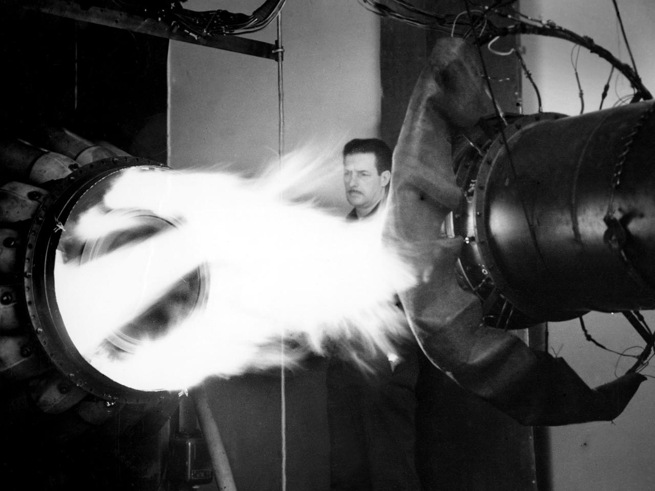
A mechanic watches the firing of a General Electric I-40 turbojet at the National Advisory Committee for Aeronautics (NACA) Lewis Flight Propulsion Laboratory. The military selected General Electric’s West Lynn facility in 1941 to secretly replicate the centrifugal turbojet engine designed by British engineer Frank Whittle. General Electric’s first attempt, the I-A, was fraught with problems. The design was improved somewhat with the subsequent I-16 engine. It was not until the engine's next reincarnation as the I-40 in 1943 that General Electric’s efforts paid off. The 4000-pound thrust I-40 was incorporated into the Lockheed Shooting Star airframe and successfully flown in June 1944. The Shooting Star became the US’s first successful jet aircraft and the first US aircraft to reach 500 miles per hour. NACA Lewis studied all of General Electric’s centrifugal turbojet models during the 1940s. In 1945 the entire Shooting Star aircraft was investigated in the Altitude Wind Tunnel. Engine compressor performance and augmentation by water injection; comparison of different fuel blends in a single combustor; and air-cooled rotors were studied. The mechanic in this photograph watches the firing of a full-scale I-40 in the Jet Propulsion Static Laboratory. The facility was quickly built in 1943 specifically in order to test the early General Electric turbojets. The I-A was secretly analyzed in the facility during the fall of 1943.
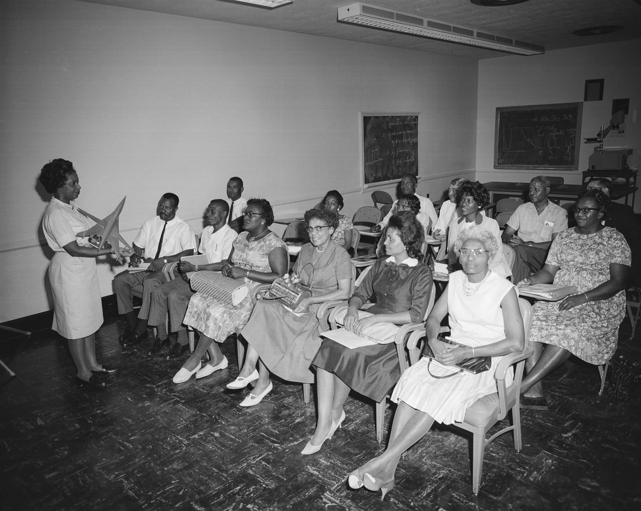
Photograph taken July 30, 1964. Mary W Jackson, Aerospace Engineer in the Large Supersonic Tunnels Branch of Full-Scale Research Division, explains the facilities used in testing research models such as SCAT. The Guidance Counseling Class from Hampton Institute visited the center on July 30 and toured a number of facilities. The purpose of the visit was to provide the counselors an opportunity to see areas of work representing fields in which their students might be employed. The group, under the direction of Professor Fissell Jones (Left, back row) of Hampton Institute, represented the states of Virginia, North Carolina, South Carolina, and Georgia. In 1958 Mary Jackson became NASA's first black female engineer. The Hampton Institute (now Hampton University) is a Historically Black College. NASA started its EEO office in 1964 and the NASA Administrator at the time, James Webb, was very enthusiastic about reaching out to universities (including HBCUs) to partner with them and to encourage students to become NASA engineers.
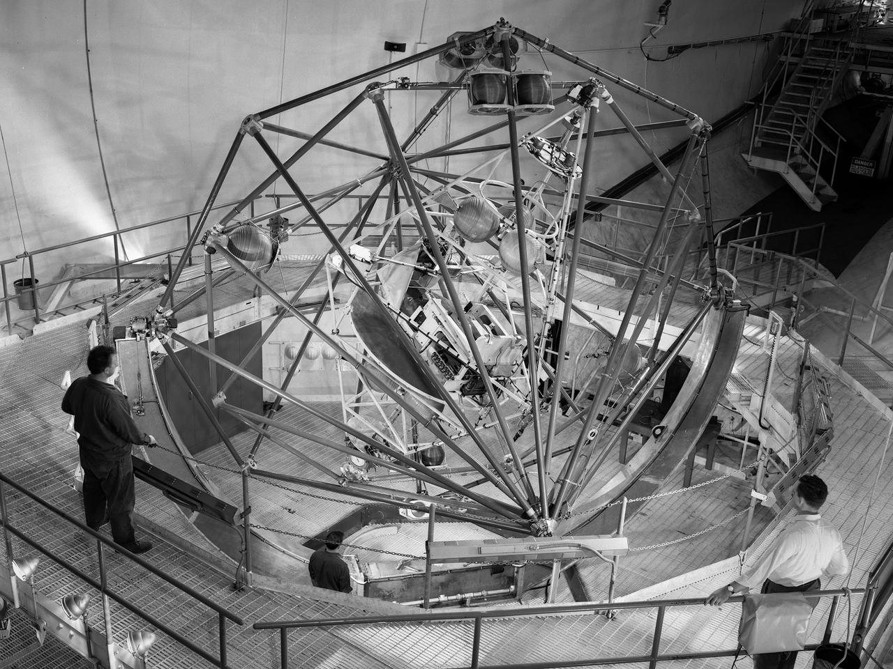
The Multi-Axis Space Test Inertial Facility (MASTIF) in the Altitude Wind Tunnel at the National Aeronautics and Space Administration (NASA) Lewis Research Center. Although the Mercury astronaut training and mission planning were handled by the Space Task Group at Langley Research Center, NASA Lewis played an important role in the program, beginning with the Big Joe launch. Big Joe was a singular attempt early in the program to use a full-scale Atlas booster and simulate the reentry of a mockup Mercury capsule without actually placing it in orbit. A unique three-axis gimbal rig was built inside Lewis’ Altitude Wind Tunnel to test Big Joe’s attitude controls. The control system was vital since the capsule would burn up on reentry if it were not positioned correctly. The mission was intended to assess the performance of the Atlas booster, the reliability of the capsule’s attitude control system and beryllium heat shield, and the capsule recovery process. The September 9, 1959 launch was a success for the control system and heatshield. Only a problem with the Atlas booster kept the mission from being a perfect success. The MASTIF was modified in late 1959 to train Project Mercury pilots to bring a spinning spacecraft under control. An astronaut was secured in a foam couch in the center of the rig. The rig then spun on three axes from 2 to 50 rotations per minute. Small nitrogen gas thrusters were used by the astronauts to bring the MASTIF under control.
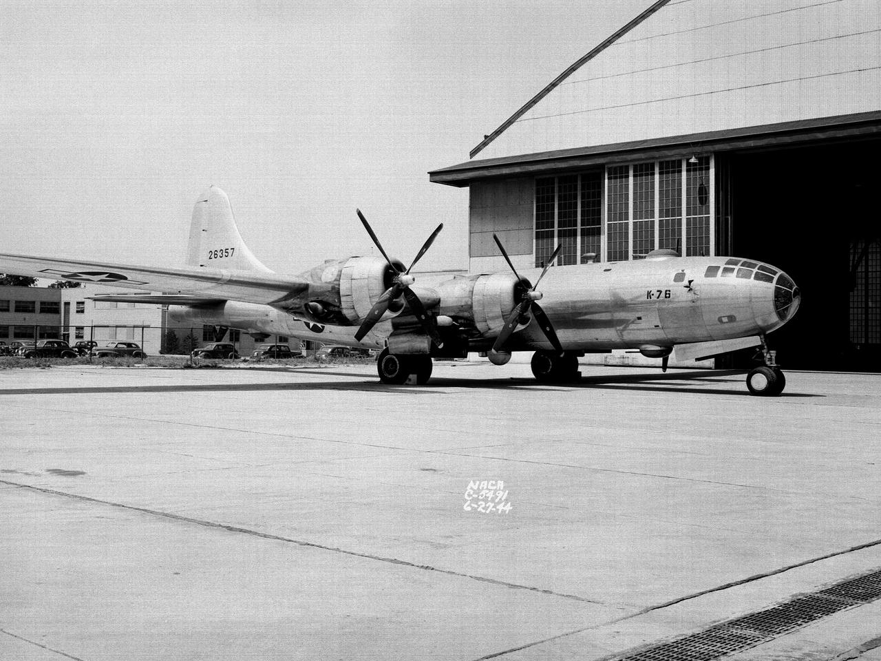
A Boeing B–29 Superfortress at the National Advisory Committee for Aeronautics (NACA) Aircraft Engine Research Laboratory in Cleveland, Ohio. The B–29 was the Army Air Forces’ deadliest weapon during the latter portion of World War II. The aircraft was significantly larger than previous bombers but could fly faster and higher. The B–29 was intended to soar above anti-aircraft fire and make pinpoint drops onto strategic targets. The bomber was forced to carry 20,000 pounds more armament than it was designed for. The extra weight pushed the B–29’s four powerful Wright R–3350 engines to their operating limits. The over-heating of the engines proved to be a dangerous problem. The military asked the NACA to tackle the issue. Full-scale engine tests on a R–3350 engine in the Prop House demonstrated that a NACA-designed impeller increased the flow rate of the fuel injection system. Altitude Wind Tunnel studies of the engine led to the reshaping of cowling inlet and outlet to improve airflow and reduce drag. Single-cylinder studies on valve failures were resolved by a slight extension of the cylinder head, and the Engine Research Building researchers combated uneven heating with a new fuel injection system. The modifications were then tried out on an actual B–29. The bomber arrived in Cleveland on June 22, 1944. The new injection impeller, ducted head baffles and instrumentation were installed on the bomber’s two left wing engines. Eleven test flights were flown over the next month with military pilots at the helm. Overall the flight tests corroborated the wind tunnel and test stand studies.
The Fan Noise Test Facility built at the Lewis Research Center to obtain far-field noise data for the National Aeronautics and Space Administration (NASA) and General Electric Quiet Engine Program. The engine incorporated existing noise reduction methods into an engine of similar power to those that propelled the Boeing 707 or McDonnell-Douglas DC-8 airliner. The new the low-bypass ratio turbofan engines of the 1960s were inherently quieter than their turbojet counterparts, researchers had a better grasp of the noise generation problem, and new acoustic technologies had emerged. Lewis contracted General Electric in 1969 to build and aerodynamically test three experimental engines with 72-inch diameter fans. The engines were then brought to Lewis and tested with an acoustically treated nacelle. This Fan Noise Test Facility was built off of the 10- by 10-Foot Supersonic Wind Tunnel’s Main Compressor and Drive Building. Lewis researchers were able to isolate the fan’s noise during these initial tests by removing the core of the engine. The Lewis test rig drove engines to takeoff tip speeds of 1160 feet per second. The facility was later used to test a series of full-scale model fans and fan noise suppressors to be used with the quiet engine. NASA researchers predicted low-speed single-stage fans without inlet guide vanes and with large spacing between rotors and stators would be quieter. General Electric modified a TF39 turbofan engine by removing the the outer protion of the fan and spacing the blade rows of the inner portion. The tests revealed that the untreated version of the engine generated less noise than was anticipated, and the acoustically treated nacelle substantially reduced engine noise.
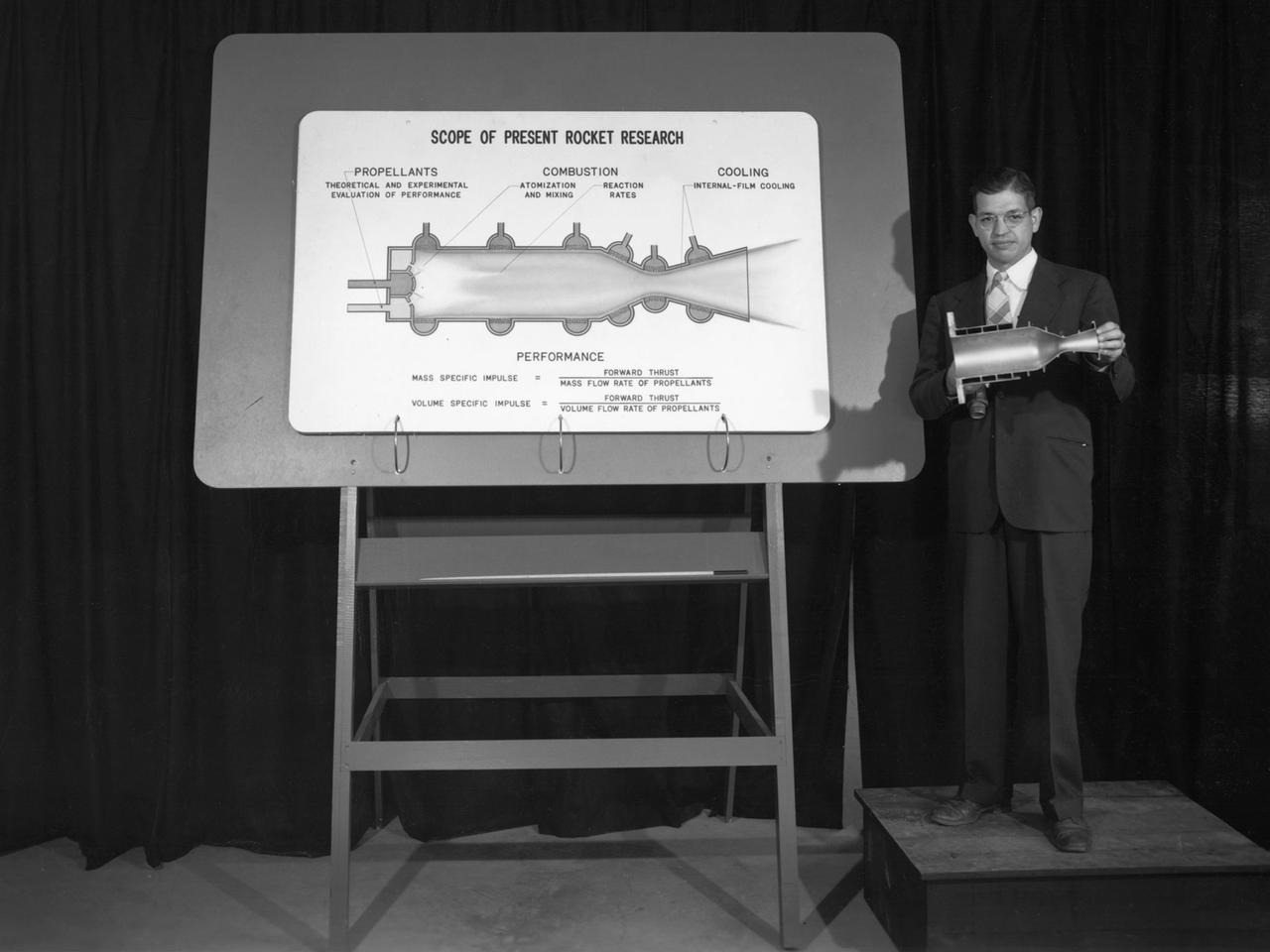
Researcher John Sloop briefs visitors on his latest rocket engine research during the 1947 Inspection at the National Advisory Committee for Aeronautics (NACA) Lewis Flight Propulsion Laboratory. The NACA had been hosting annual Aircraft Engineering Conferences, better known as Inspections, since 1926. Individuals from the manufacturing industry, military, and university settings were invited to tour the NACA laboratories. There were a series of stops on the tour, mostly at test facilities, where researchers would brief the group on the latest efforts in their particular field. The Inspections grew in size and scope over the years and by the mid-1940s required multiple days. The three-day 1947 Inspection was the first time the event was held at NACA Lewis. Over 800 scientists, industrialists, and military leaders attended the three-day event. Talks were given at the Altitude Wind Tunnel, Four Burner Area, Engine Research Building, and other facilities. An array of topics were discussed, including full-scale engine testing, ramjets, axial-flow compressors, turbojets, fuels, icing, and materials. The NACA Lewis staff and their families were able to view the same presentations after the Inspection was over. Sloop, a researcher in the Fuels and Thermodynamics Division, briefed visitors on NACA Lewis’ early research in rocket engine propellants, combustion, and cooling. This early NACA Lewis work led to the development of liquid hydrogen as a viable propellant in the late 1950s.