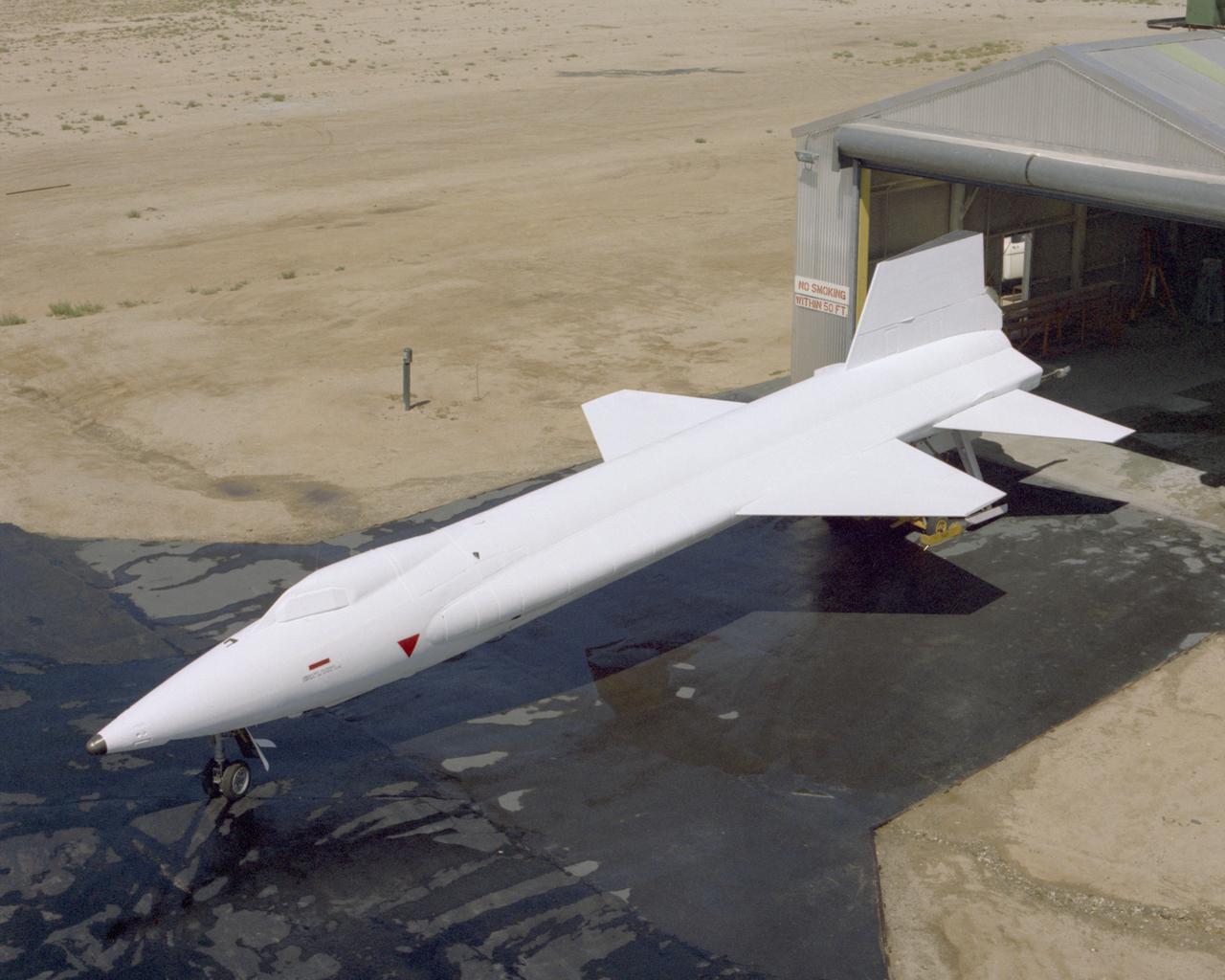
X-15A-2 is rolled out of the paint shop after having the full scale ablative applied. In June 1967, the X-15A-2 rocket-powered research aircraft received a full-scale ablative coating to protect the craft from the high temperatures associated with hypersonic flight (above Mach 5). This pink eraser-like substance, applied to the X-15A-2 aircraft (56-6671), was then covered with a white sealant coat before flight. This coating would help the #2 aircraft reach the record speed of 4,520 mph (Mach 6.7).
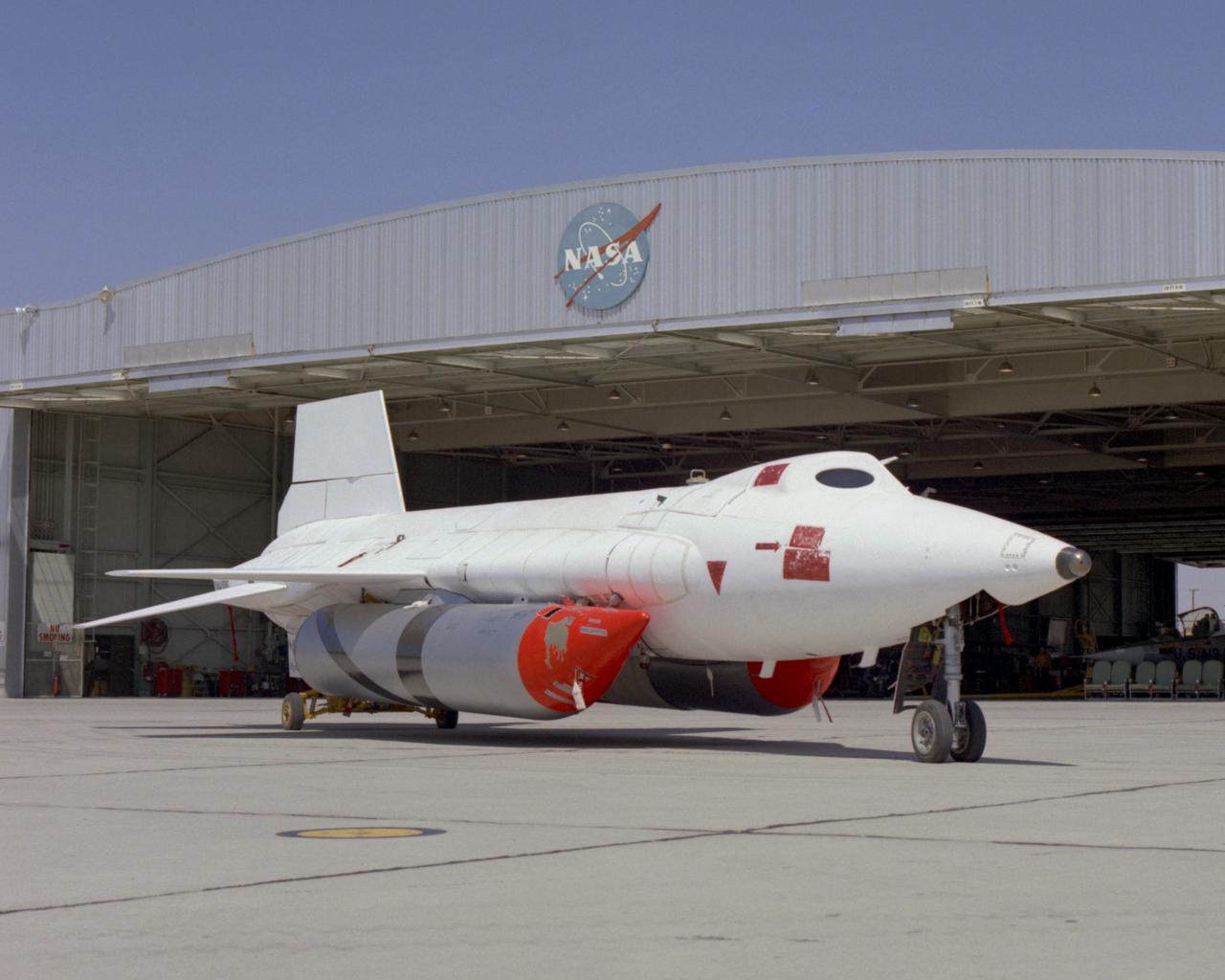
X-15A-2 with full scale ablative and external tanks installed parked in front of hangar. In June 1967, the X-15A-2 rocket-powered research aircraft received a full-scale ablative coating to protect the craft from the high temperatures associated with hypersonic flight (above Mach 5). This pink eraser-like substance, applied to the X-15A-2 aircraft (56-6671), was then covered with a white sealant coat before flight. This coating would help the #2 aircraft reach the record speed of 4,520 mph (Mach 6.7).
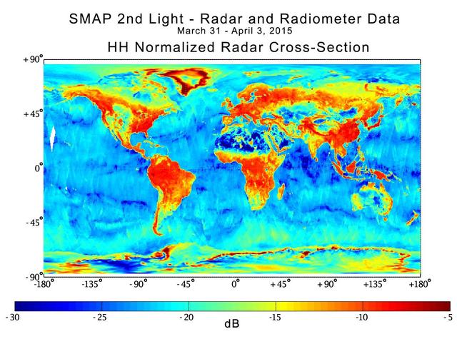
With its antenna now spinning at full speed, NASA new Soil Moisture Active Passive SMAP observatory has successfully re-tested its science instruments and generated its first global maps, a key step to beginning routine science operations in May, 2015

With its antenna now spinning at full speed, NASA new Soil Moisture Active Passive SMAP observatory has successfully re-tested its science instruments and generated its first global maps, a key step to beginning routine science operations in May, 2015
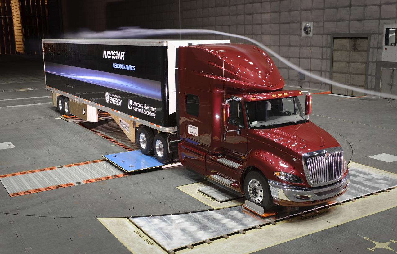
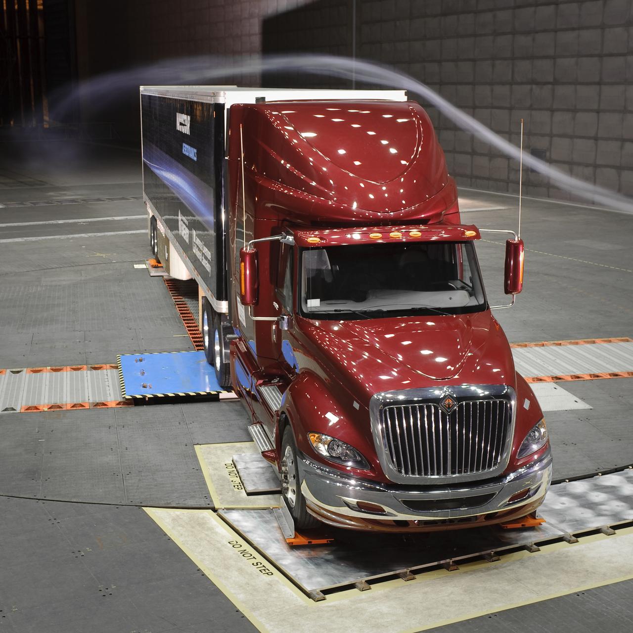
Lawrence Livermore National Labs (LLNL), Navistar and the Department of Energy conduct tests in the NASA Ames National Full-scale Aerodynamic Complex 80x120_foot wind tunnel. The LLNL project is aimed at aerodynamic truck and trailer devices that can reduce fuel consumption at highway speed by 10 percent. Smoke test demo.
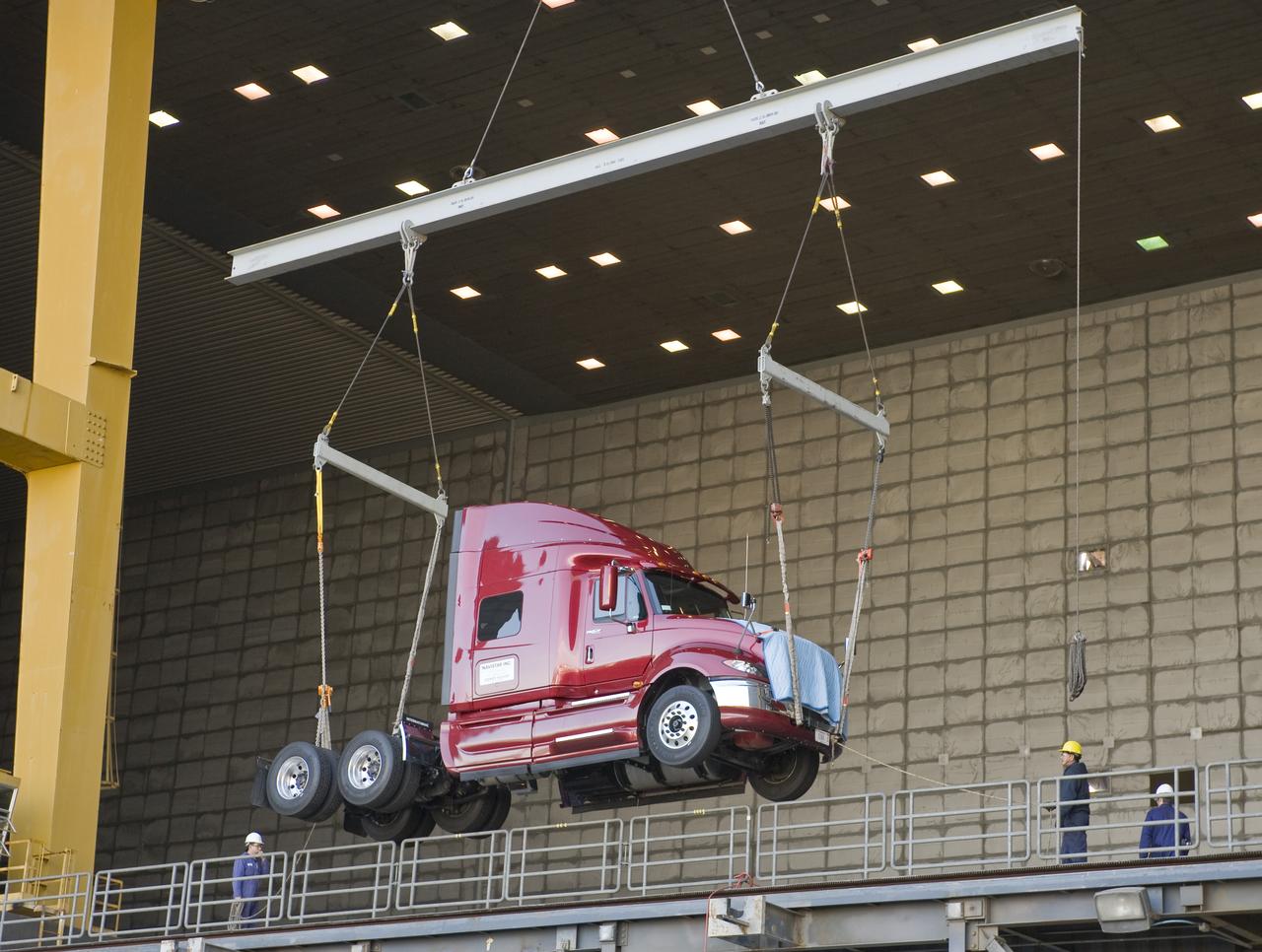
Lawrence Livermore National Labs (LLNL), Navistar and the Department of Energy conduct tests in the NASA Ames National Full-scale Aerodynamic Complex 80x120_foot wind tunnel. The LLNL project is aimed at aerodynamic truck and trailer devices that can reduce fuel consumption at highway speed by 10 percent. Cab being lifted into the tunnel.
Lawrence Livermore National Labs (LLNL), Navistar and the Department of Energy conduct tests in the NASA Ames National Full-scale Aerodynamic Complex 80x120_foot wind tunnel. The LLNL project is aimed at aerodynamic truck and trailer devices that can reduce fuel consumption at highway speed by 10 percent. Smoke test demo.
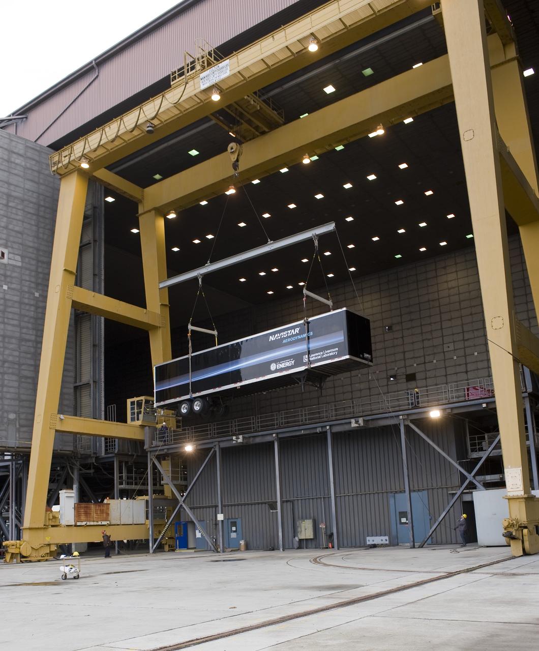
Lawrence Livermore National Labs (LLNL), Navistar and the Department of Energy conduct tests in the NASA Ames National Full-scale Aerodynamic Complex 80x120_foot wind tunnel. The LLNL project is aimed at aerodynamic truck and trailer devices that can reduce fuel consumption at highway speed by 10 percent. Trailer being lifted into the tunnel.
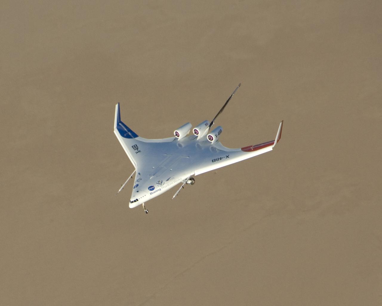
Boeing Phantom Works' subscale Blended Wing Body technology demonstration aircraft began its initial flight tests from NASA's Dryden Flight Research Center at Edwards Air Force Base, Calif. in the summer of 2007. The 8.5 percent dynamically scaled unmanned aircraft, designated the X-48B by the Air Force, is designed to mimic the aerodynamic characteristics of a full-scale large cargo transport aircraft with the same blended wing body shape. The initial flight tests focused on evaluation of the X-48B's low-speed flight characteristics and handling qualities. About 25 flights were planned to gather data in these low-speed flight regimes. Based on the results of the initial flight test series, a second set of flight tests was planned to test the aircraft's low-noise and handling characteristics at transonic speeds.
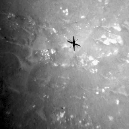
The shadow of NASA's Ingenuity Mars Helicopter can be seen in this animated GIF composed of images taken by its black-and-white navigation camera during the rotocraft's third flight, on April 25, 2021. The camera, which tracks surface features below the helicopter, takes images at a rate at which the helicopter's blades appear frozen in place, despite making 21 full rotations in-between each image. At full speed, the blades spin at 2,537 rpm. The images are aligned entirely using Ingenuity's on-board position tracking system highlighting the stability and accuracy of the navigation algorithm. Movie available at https://photojournal.jpl.nasa.gov/catalog/PIA24644
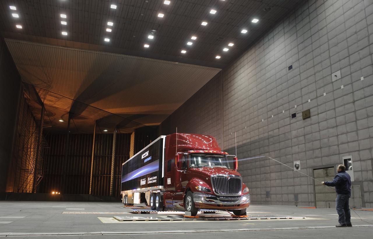
Lawrence Livermore National Labs (LLNL), Navistar and the Department of Energy conduct tests in the NASA Ames National Full-scale Aerodynamic Complex 80x120_foot wind tunnel. The LLNL project is aimed at aerodynamic truck and trailer devices that can reduce fuel consumption at highway speed by 10 percent. Smoke test demo with Ron Schoon, Navistar.
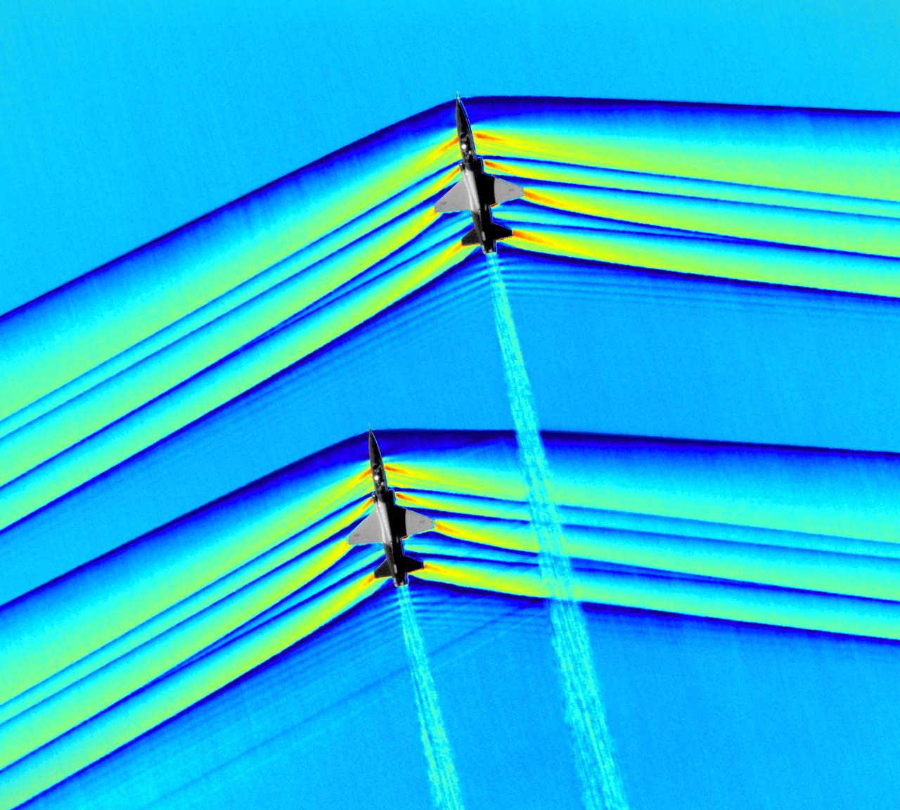
Composite image of Background Oriented Schlieren (BOS) data (contour) with a cut-out images of the T-38’s during a Mach Number 1.01 pass. This data is the first time shockwave interactions between two full scale aircraft traveling faster than the speed of sound have been imaged and shown with schlieren visualization. Original recording of the pass taken in the Black Mountain Supersonic Corridor at near Edwards AFB in December of 2018. Image acquired by JT Heineck, schlieren data processed by Neal Smith
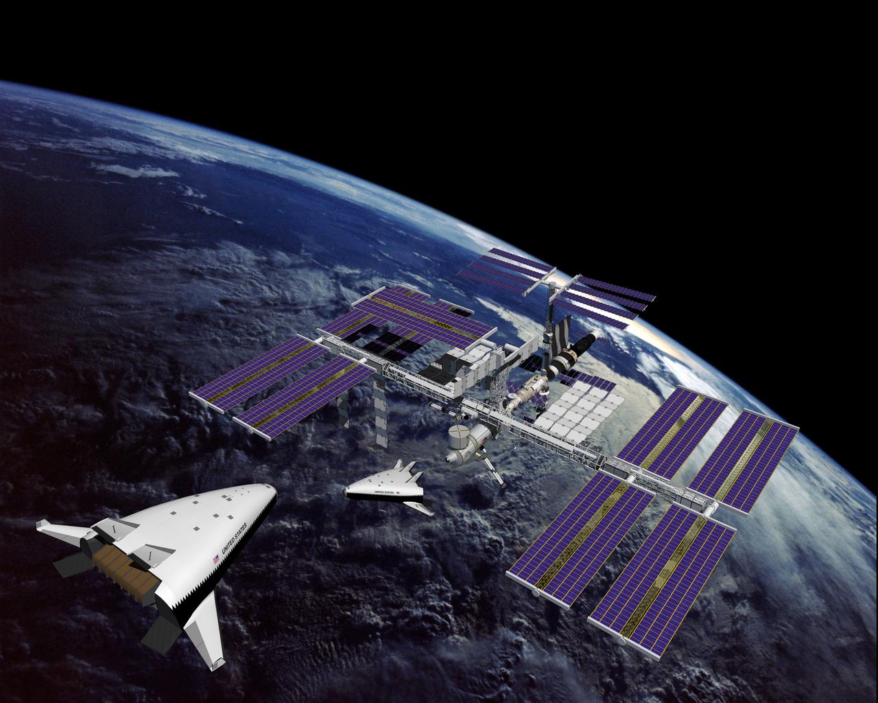
This is an artist's concept of the completely operational International Space Station being approached by an X-33 Reusable Launch Vehicle (RLV). The X-33 program was designed to pave the way to a full-scale, commercially developed RLV as the flagship technology demonstrator for technologies that would lower the cost of access to space. It is unpiloted, taking off vertically like a rocket, reaching an altitude of up to 60 miles and speeds between Mach 13 and 15, and landing horizontally like an airplane. The X-33 program was cancelled in 2001.
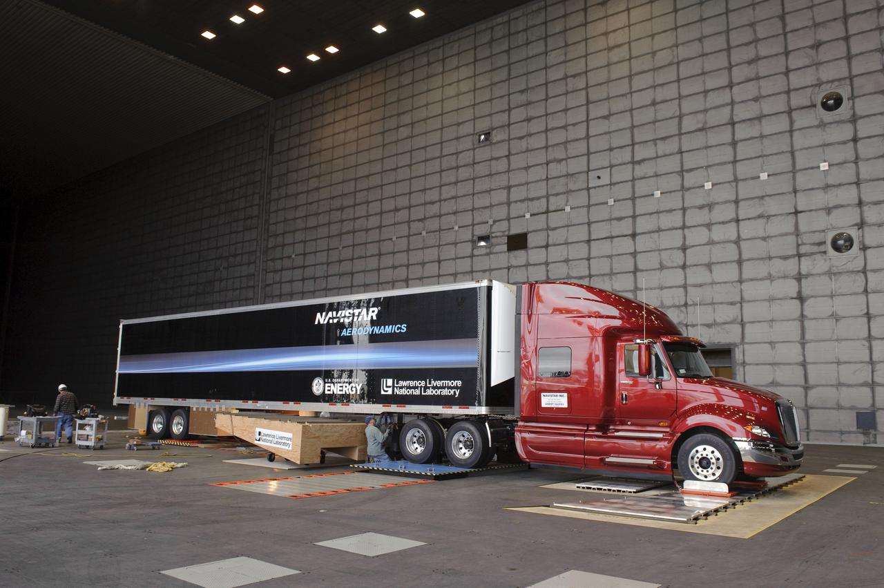
Lawrence Livermore National Labs (LLNL), Navistar and the Department of Energy conduct tests in the NASA Ames National Full-scale Aerodynamic Complex 80x120_foot wind tunnel. The LLNL project is aimed at aerodynamic truck and trailer devices that can reduce fuel consumption at highway speed by 10 percent. LLNL's test piece is being installed on truck.

Lawrence Livermore National Labs (LLNL), Navistar and the Department of Energy conduct tests in the NASA Ames National Full-scale Aerodynamic Complex 80x120_foot wind tunnel. The LLNL project is aimed at aerodynamic truck and trailer devices that can reduce fuel consumption at highway speed by 10 percent. Smoke test demo with Ron Schoon, Navistar.
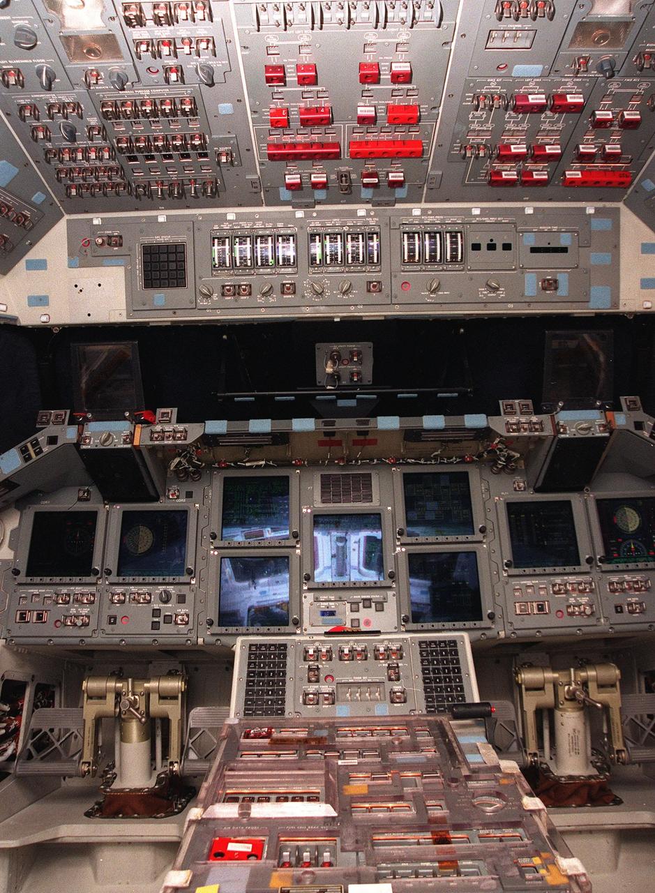
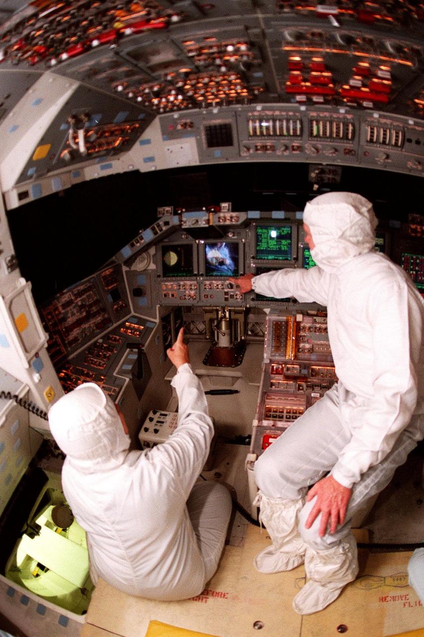
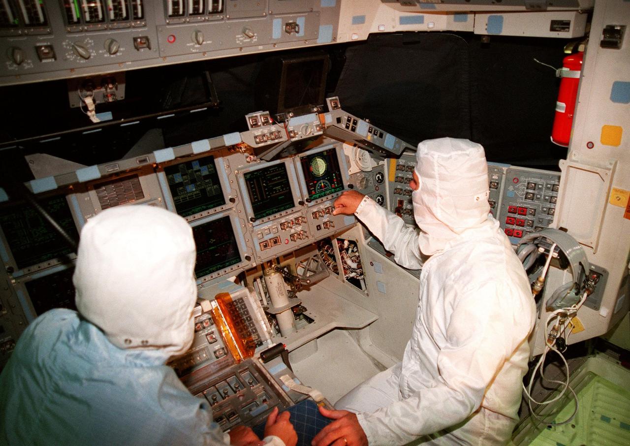
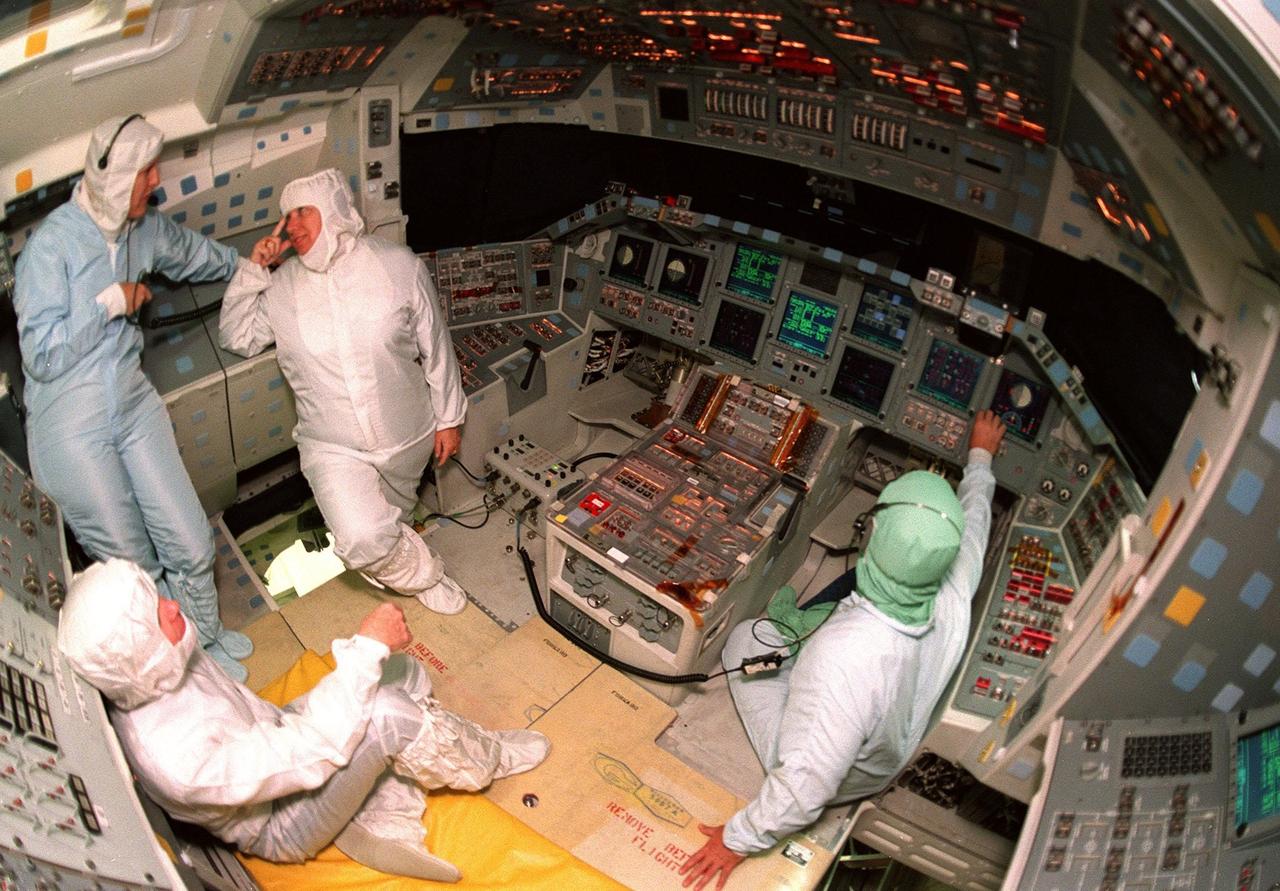
The cockpit of the orbiter Atlantis is revealed with its new full-color, flat panel Multifunction Electronic Display Subsystem (MEDS), also called the "glass cockpit." The recently installed MEDS upgrade improves crew/orbiter interaction with easy-to-read, graphic portrayals of key flight indicators like attitude display and mach speed. The installation makes Atlantis the most modern orbiter in the fleet and equals the systems on current commercial jet airliners and military aircraft. Atlantis is scheduled to fly on mission STS-101 in early December

Composite image of Background Oriented Schlieren (BOS) data (contour) with a cut-out images of the T-38’s during a Mach Number 1.01 pass. This data is the first time shockwave interactions between two full scale aircraft traveling faster than the speed of sound have been imaged and shown with schlieren visualization. Original recording of the pass taken in the Black Mountain Supersonic Corridor at near Edwards AFB in December of 2018. Image acquired by JT Heineck, schlieren data processed by Neal Smith.
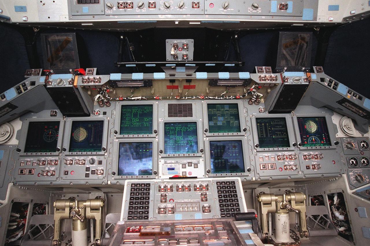
In this broad view, the new full-color, flat panel Multifunction Electronic Display Subsystem (MEDS) is shown in the cockpit of the orbiter Atlantis. It is often called the "glass cockpit." The recently installed MEDS upgrade improves crew/orbiter interaction with easy-to-read, graphic portrayals of key flight indicators like attitude display and mach speed. The installation makes Atlantis the most modern orbiter in the fleet and equals the systems on current commercial jet airliners and military aircraft. Atlantis is scheduled to fly on mission STS-101 in early December
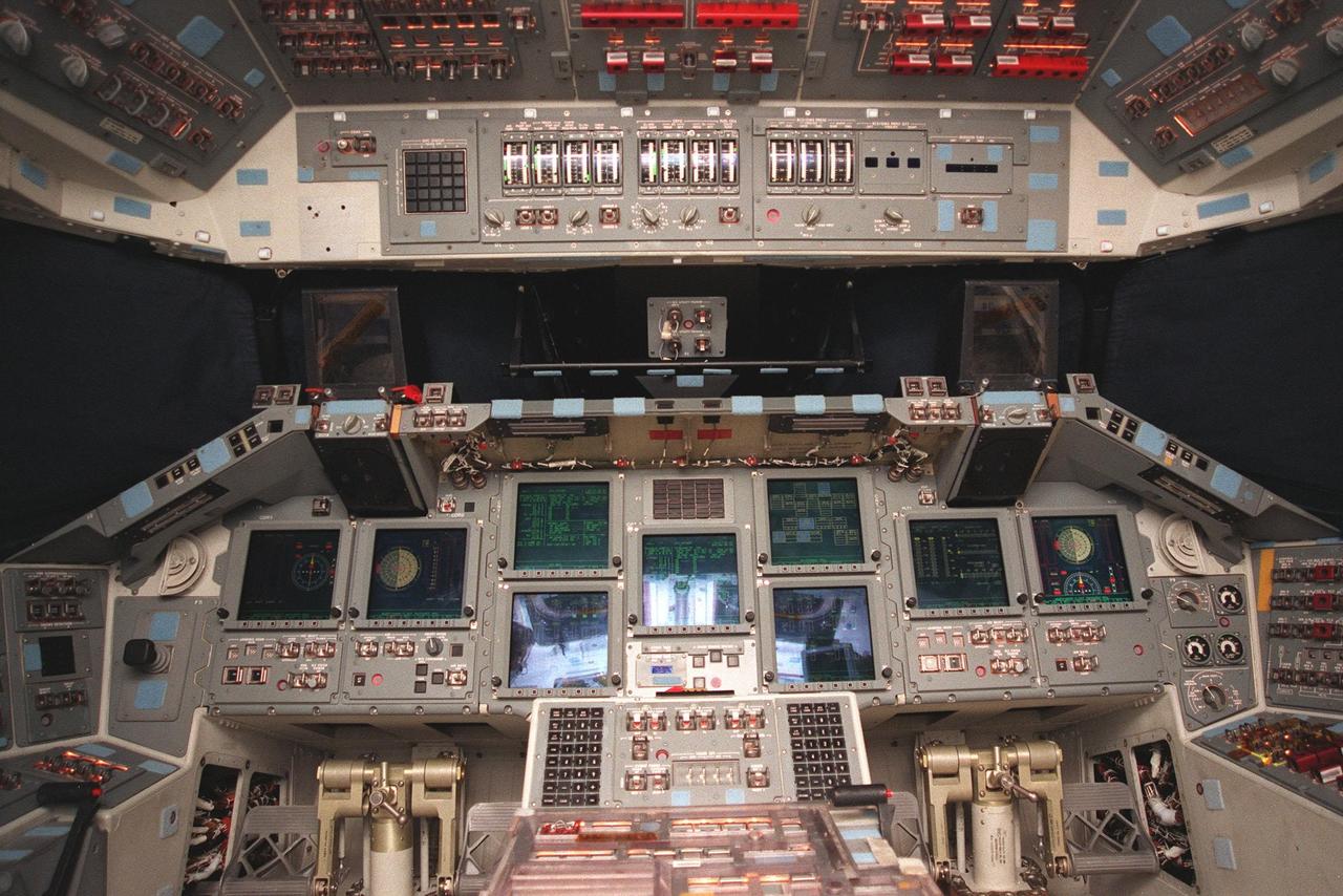
A new full-color, flat panel Multifunction Electronic Display Subsystem (MEDS) is shown in the cockpit of the orbiter Atlantis. It is often called the "glass cockpit." The recently installed MEDS upgrade improves crew/orbiter interaction with easy-to-read, graphic portrayals of key flight indicators like attitude display and mach speed. The installation makes Atlantis the most modern orbiter in the fleet and equals the systems on current commercial jet airliners and military aircraft. Atlantis is scheduled to fly on mission STS-101 in early December

Composite image of Background Oriented Schlieren (BOS) data (contour) with a cut-out images of the T-38’s during a Mach Number 1.01 pass. This data is the first time shockwave interactions between two full scale aircraft traveling faster than the speed of sound have been imaged and shown with schlieren visualization. Original recording of the pass taken in the Black Mountain Supersonic Corridor at near Edwards AFB in December of 2018. Image acquired by JT Heineck, schlieren data processed by Neal Smith
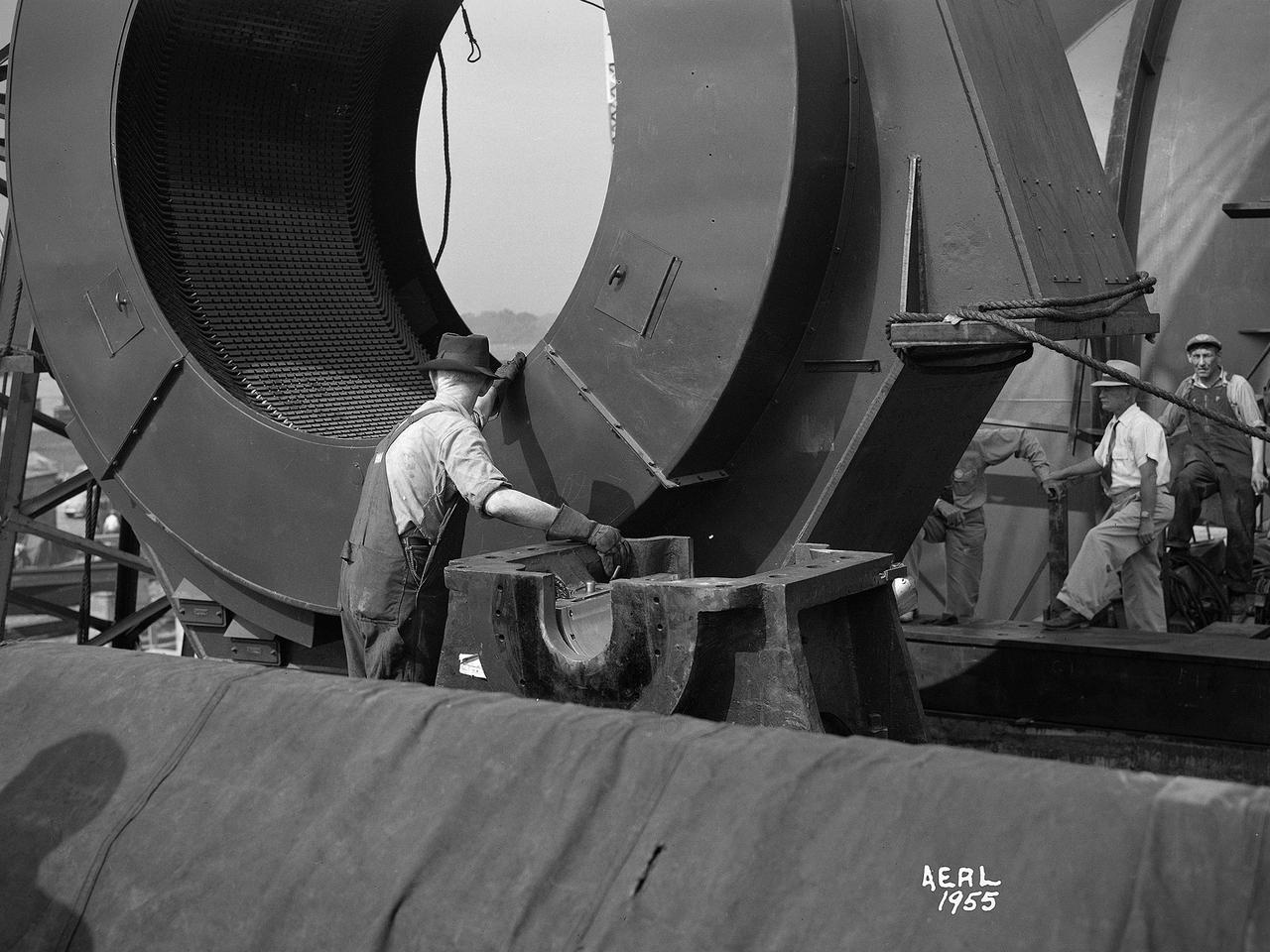
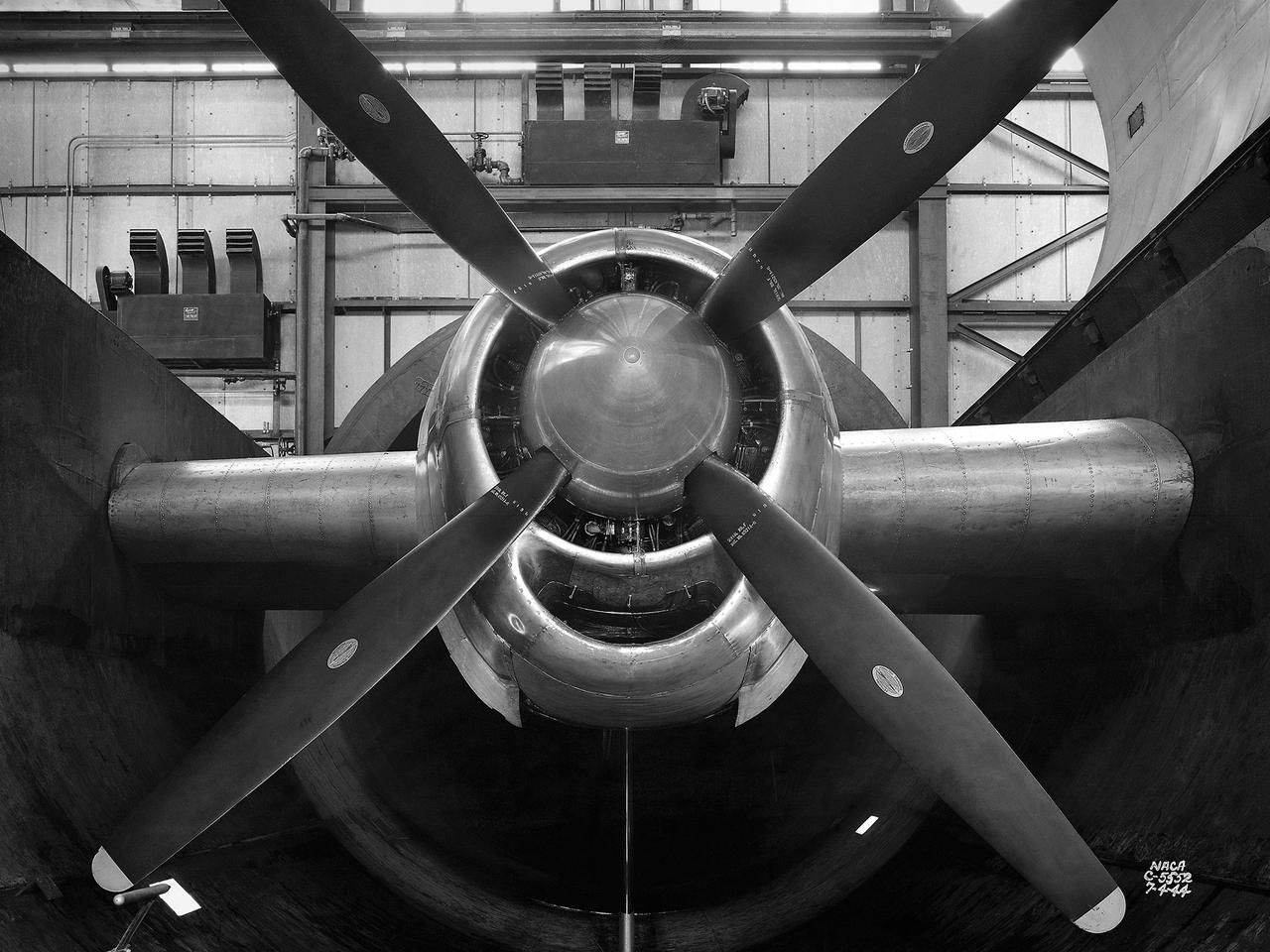
Construction workers install the drive motor for the Altitude Wind Tunnel (AWT) in the Exhauster Building at the National Advisory Committee for Aeronautics (NACA) Aircraft Engine Research Laboratory. The AWT was capable of operating full-scale engines in air density, speed, and temperature similar to that found at high altitudes. The tunnel could produce wind speeds up to 500 miles per hour through a 20-foot-diameter test section at the standard operating altitude of 30,000 feet. The airflow was created by a large wooden fan near the tunnel’s southeast corner. This photograph shows the installation of the 18,000-horsepower drive motor inside the adjoining Exhauster Building in July 1943. The General Electric motor, whose support frame is seen in this photograph, connected to a drive shaft that extended from the building, through the tunnel shell, and into a 12-bladed, 31-foot-diameter spruce wood fan. Flexible couplings on the shaft allowed for the movement of the shell. The corner of the Exhauster Building was built around the motor after its installation. The General Electric induction motor could produce 10 to 410 revolutions per minute and create wind speeds up to 500 miles per hour, or Mach 0.63, at 30,000 feet. The AWT became operational in January 1944 and tested piston, turbojet and ramjet engines for nearly 20 years.
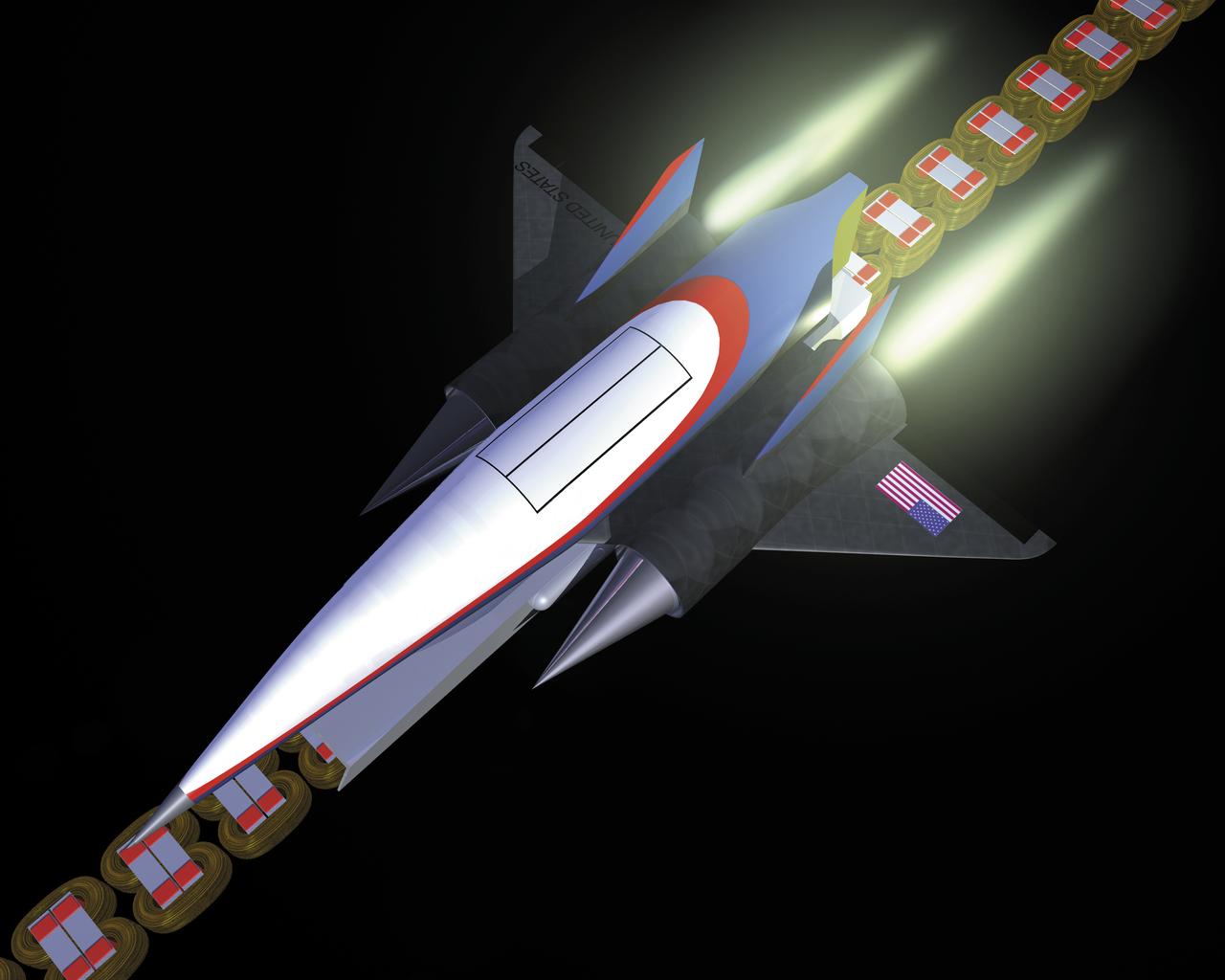
This artist’s concept depicts a Magnetic Launch Assist vehicle clearing the track and shifting to rocket engines for launch into orbit. The system, formerly referred as the Magnetic Levitation (MagLev) system, is a launch system developed and tested by Engineers at the Marshall Space Flight Center (MSFC) that could levitate and accelerate a launch vehicle along a track at high speeds before it leaves the ground. Using an off-board electric energy source and magnetic fields, a Magnetic Launch Assist system would drive a spacecraft along a horizontal track until it reaches desired speeds. The system is similar to high-speed trains and roller coasters that use high-strength magnets to lift and propel a vehicle a couple of inches above a guideway. A full-scale, operational track would be about 1.5-miles long, capable of accelerating a vehicle to 600 mph in 9.5 seconds, and the vehicle would then shift to rocket engines for launch into orbit. The major advantages of launch assist for NASA launch vehicles is that it reduces the weight of the take-off, the landing gear, the wing size, and less propellant resulting in significant cost savings. The US Navy and the British MOD (Ministry of Defense) are planning to use magnetic launch assist for their next generation aircraft carriers as the aircraft launch system. The US Army is considering using this technology for launching target drones for anti-aircraft training.
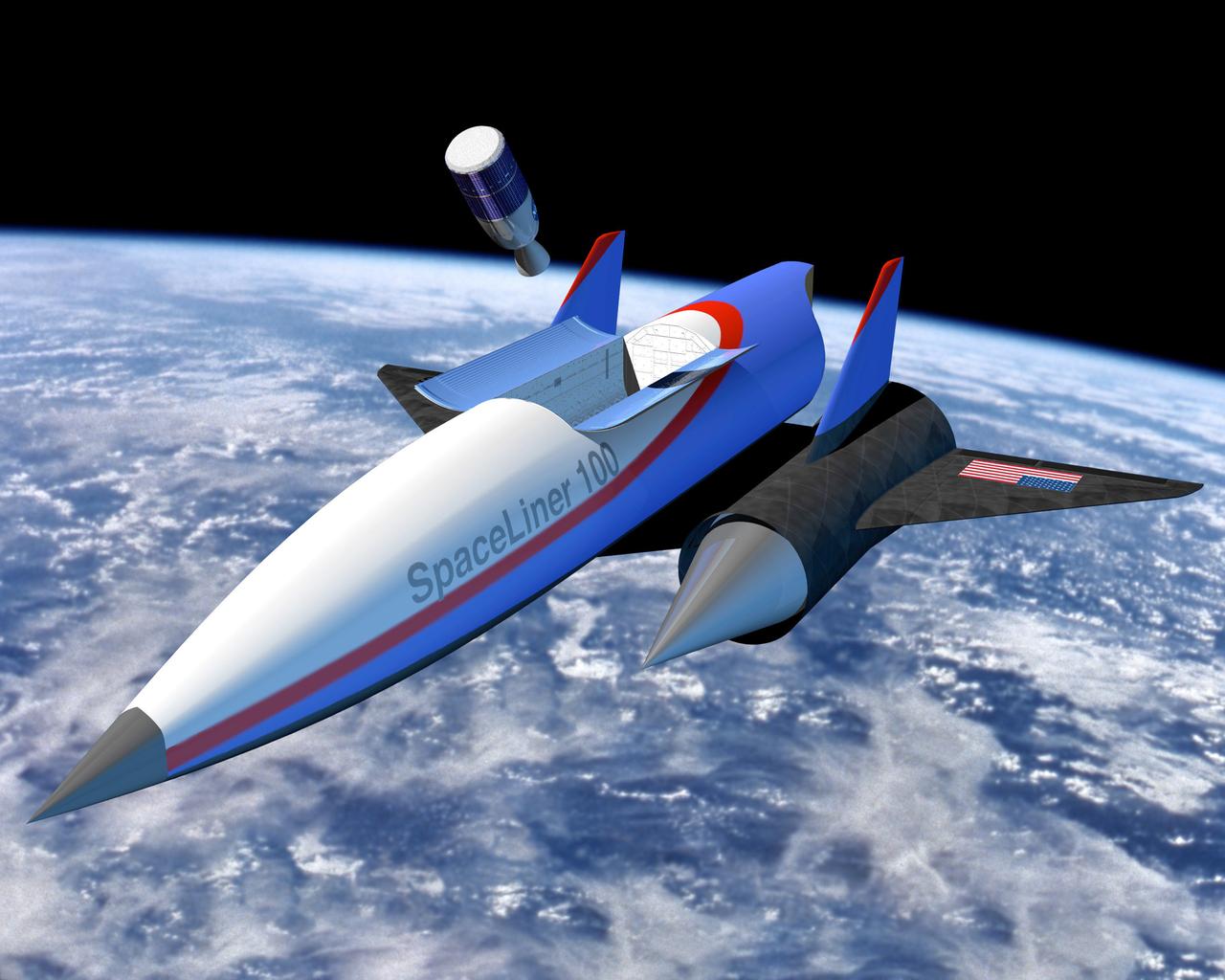
This artist’s concept depicts a Magnetic Launch Assist vehicle in orbit. Formerly referred to as the Magnetic Levitation (Maglev) system, the Magnetic Launch Assist system is a launch system developed and tested by engineers at the Marshall Space Flight Center (MSFC) that could levitate and accelerate a launch vehicle along a track at high speeds before it leaves the ground. Using electricity and magnetic fields, a Magnetic Launch Assist system would drive a spacecraft along a horizontal track until it reaches desired speeds. The system is similar to high-speed trains and roller coasters that use high-strength magnets to lift and propel a vehicle a couple of inches above a guideway. A full-scale, operational track would be about 1.5-miles long, capable of accelerating a vehicle to 600 mph in 9.5 seconds, and the vehicle would then shift to rocket engines for launch into orbit. The major advantages of launch assist for NASA launch vehicles is that it reduces the weight of the take-off, the landing gear, the wing size, and less propellant resulting in significant cost savings. The US Navy and the British MOD (Ministry of Defense) are planning to use magnetic launch assist for their next generation aircraft carriers as the aircraft launch system. The US Army is considering using this technology for launching target drones for anti-aircraft training.
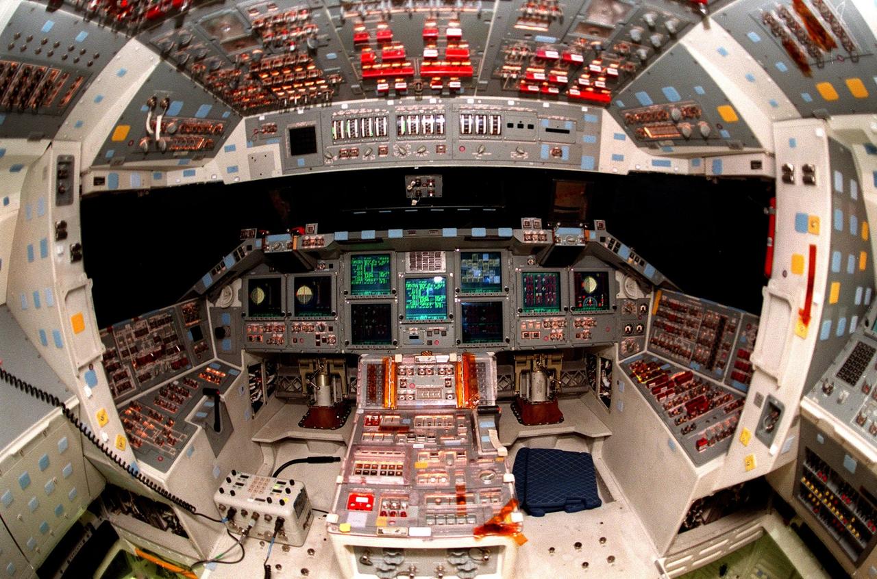
KENNEDY SPACE CENTER, FLA. -- The cockpit of the orbiter Atlantis is seen in the round, revealing the new full-color flat panel Multifunction Electronic Display Subsystem (MEDS), also called the "glass cockpit." The recently installed MEDS upgrade improves crew/orbiter interaction with easy-to-read, graphic portrayals of key flight indicators like attitude display and mach speed. The installation makes Atlantis the most modern orbiter in the fleet and equals the systems on current commercial jet airliners and military aircraft. Atlantis is scheduled to fly on mission STS-101 in early December
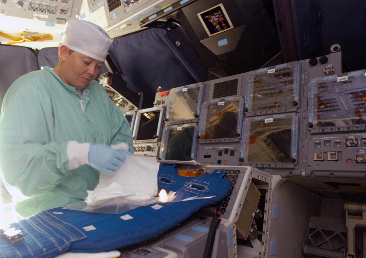
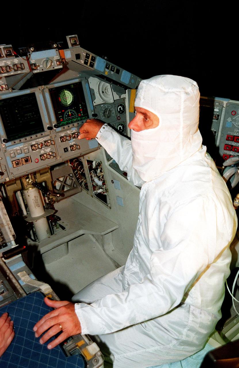
KENNEDY SPACE CENTER, FLA. - Carmen Prater, with United Space Alliance, works on the flight deck of the orbiter Endeavour in bay 2 of the Orbiter Processing Facility. She wears a “bunny suit,” clean room attire required for anyone coming in close proximity to the orbiter. Endeavour is undergoing major modifications, which include inspecting more than 150 miles of wiring, bonding 1,000 thermal tiles, and installing the Multifunction Electronic Display Subsystem - a state-of-the-art “glass cockpit.” The full-color, flat-panel MEDS upgrade improves crew/orbiter interaction with easy-to-read, graphic portrayals of key flight indicators like attitude display and mach speed.
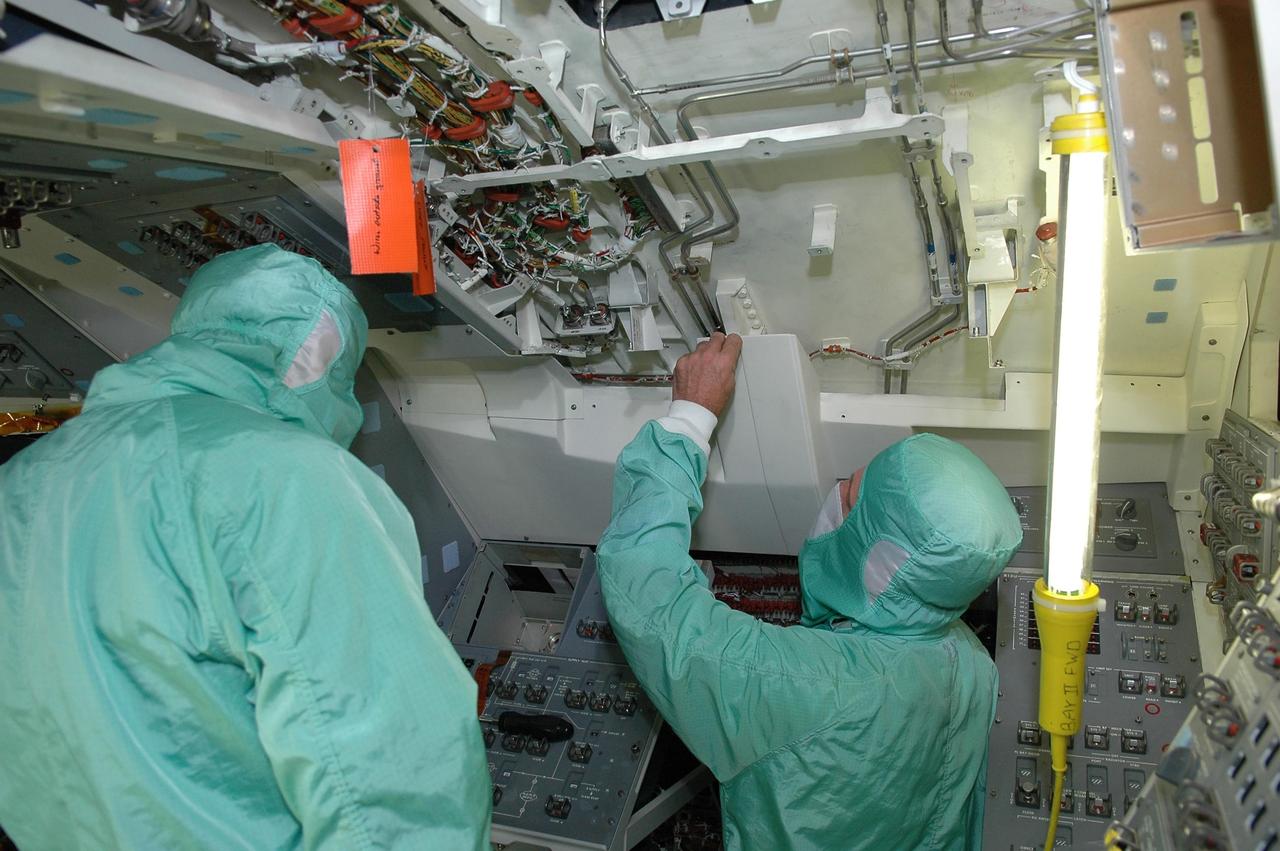
KENNEDY SPACE CENTER, FLA. - In bay 2 of the Orbiter Processing Facility, workers are installing the Multifunction Electronic Display Subsystem - a state-of-the-art “glass cockpit” - on the orbiter Endeavour. The “bunny suits” they are wearing are clean room attire required for anyone coming in close proximity to the orbiter. The full-color, flat-panel MEDS upgrade improves crew/orbiter interaction with easy-to-read, graphic portrayals of key flight indicators like attitude display and mach speed. Endeavour is undergoing major modifications, which include inspecting more than 150 miles of wiring and bonding 1,000 thermal tiles, along with installing the display system.
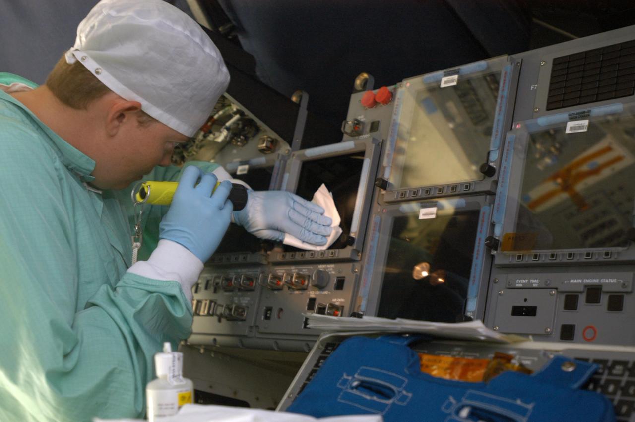
KENNEDY SPACE CENTER, FLA. - Carmen Prater, with United Space Alliance, cleans a screen on the flight deck of the orbiter Endeavour in bay 2 of the Orbiter Processing Facility. She wears a “bunny suit,” clean room attire required for anyone coming in close proximity to the orbiter. Endeavour is undergoing major modifications, which include inspecting more than 150 miles of wiring, bonding 1,000 thermal tiles, and installing the Multifunction Electronic Display Subsystem - a state-of-the-art “glass cockpit.” The full-color, flat-panel MEDS upgrade improves crew/orbiter interaction with easy-to-read, graphic portrayals of key flight indicators like attitude display and mach speed.
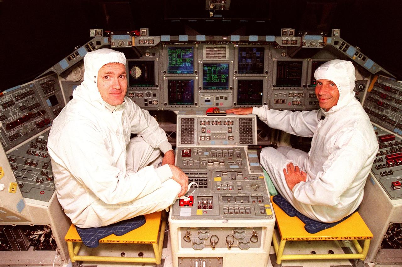
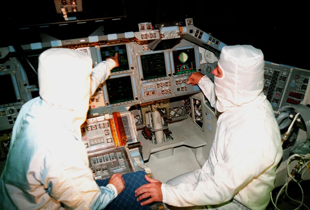
STS-101 Commander James Halsell (left) and STS-98 Commander Ken Cockrell (right) pause for a photo while looking over the recently installed Multifunction Electronic Display Subsystem (MEDS) in the cockpit of the orbiter Atlantis. The new full-color, flat panel MEDS improves crew/orbiter interaction with easy-to-read, graphic portrayals of key flight indicators like attitude display and mach speed. The installation makes Atlantis the most modern orbiter in the fleet and equals the systems on current commercial jet airliners and military aircraft. The first flight of the upgraded Atlantis is STS-101, scheduled for launch in December 1999; the second flight, STS-98, is scheduled for launch in April 2000
KENNEDY SPACE CENTER, FLA. -- Inside the orbiter Atlantis, JoAnn Morgan, Associate Director for Advanced Development and Shuttle Upgrades, and Roy Bridges Jr., Center Director, get a closeup view of the new full-color flat panel Multifunction Electronic Display Subsystem (MEDS), also called the "glass cockpit." The MEDS upgrade improves crew/orbiter interaction with easy-to-read, graphic portrayals of key flight indicators like attitude display and mach speed. The installation makes Atlantis the most modern orbiter in the fleet and equals the systems on current commercial jet airliners and military aircraft. Atlantis is scheduled to fly on mission STS-101 in early December
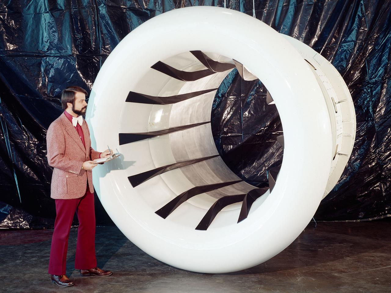
Brent Miller, of the V/STOL and Noise Division at the National Aeronautics and Space Administration (NASA) Lewis Research Center, poses with a sonic inlet for the NASA Quiet Engine Program. NASA Lewis had first investigated methods for reducing aircraft engine noise in the mid-1950s. Those efforts were resurrected and expanded in the late 1960s. The researchers found that the use of a sonic, or high-throat-Mach-number, inlet was effective at reducing the noise from the engine inlet. The device accelerated the inlet air to near-sonic speeds which kept the forward moving sound waves away from the inlet. The device also deflected the sound waves into the wall to further reduce the noise. NASA Lewis researchers tested models of the sonic inlet in their 9- by 15-Foot Low Speed Wind Tunnel. They found that the general level of aerodynamic performance was good. The tests during simulated takeoff and landing conditions demonstrated the sonic inlet’s ability to provide good aerodynamic and acoustic performance The researchers then successfully tested two full-scale sonic inlet designs, one from Pratt and Whitney and one from General Electric, with fans. A full-scale engine was installed on a thrust stand to determine the sonic inlet’s effect on the engine’s performance. The amount of noise reduction increased as the inlet flow velocity increased, but the full-scale tests did not produce as great a decrease in noise as the earlier small-scale tests.
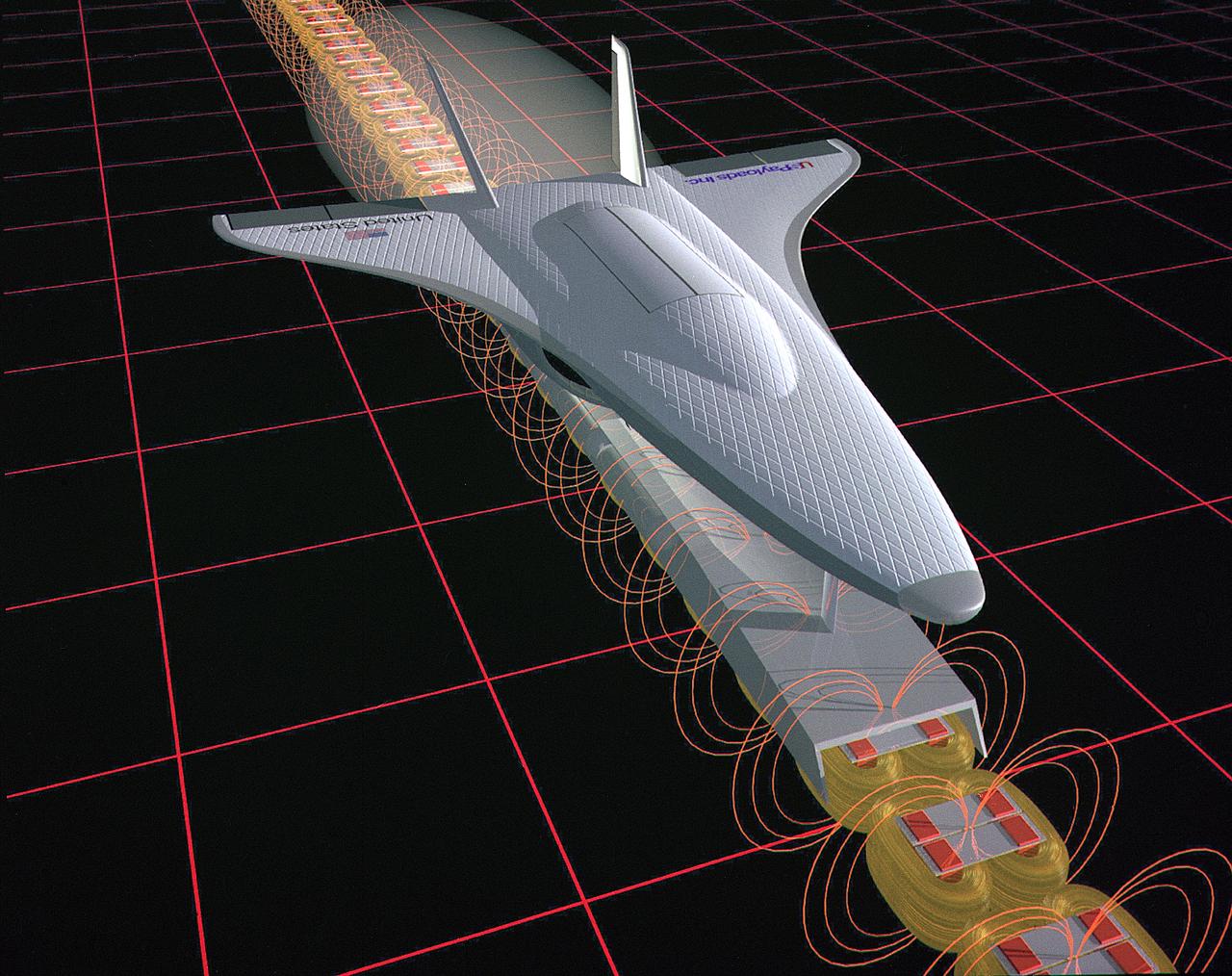
This illustration is an artist’s concept of a Magnetic Launch Assist System, formerly referred as the Magnetic Levitation (Maglev) system, for space launch. Overcoming the grip of Earth’s gravity is a supreme challenge for engineers who design rockets that leave the planet. Engineers at the Marshall Space Flight Center have developed and tested Magnetic Launch Assist System technologies that could levitate and accelerate a launch vehicle along a track at high speeds before it leaves the ground. Using electricity and magnetic fields, a Magnetic Launch Assist system would drive a spacecraft along a horizontal track until it reaches desired speeds. A full-scale, operational track would be about 1.5-miles long and capable of accelerating a vehicle to 600 mph in 9.5 seconds. The major advantages of launch assist for NASA launch vehicles is that it reduces the weight of the take-off, landing gear and the wing size, as well as the elimination of propellant weight resulting in significant cost savings. The US Navy and the British MOD (Ministry of Defense) are planning to use magnetic launch assist for their next generation aircraft carriers as the aircraft launch system. The US Army is considering using this technology for launching target drones for anti-aircraft training.

In this image, the NASA/ESA Hubble Space Telescope has captured the smoking gun of a newborn star, the Herbig–Haro objects numbered 7 to 11 (HH 7–11). These five objects, visible in blue in the top center of the image, lie within NGC 1333, a reflection nebula full of gas and dust found about a thousand light-years away from Earth. Bright patches of nebulosity near newborn stars, Herbig-Haro objects like HH 7–11 are transient phenomena. Traveling away from the star that created them at a speed of up to about 150,000 miles per hour, they disappear into nothingness within a few tens of thousands of years. The young star that is the source of HH 7–11 is called SVS 13, and all five objects are moving away from SVS 13 toward the upper left. The current distance between HH 7 and SVS 13 is about 20,000 times the distance between Earth and the Sun. Herbig–Haro objects are formed when jets of ionized gas ejected by a young star collide with nearby clouds of gas and dust at high speeds. The Herbig-Haro objects visible in this image are no exception to this and were formed when the jets from the newborn star SVS 13 collided with the surrounding clouds. These collisions created the five brilliant clumps of light within the reflection nebula.
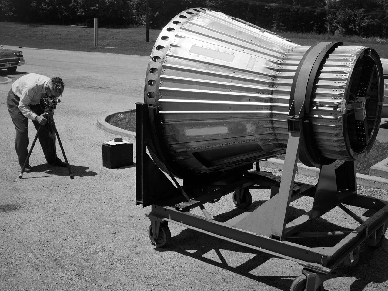
National Aeronautics and Space Administration (NASA) photographer Arthur Laufman sets up a camera to film a Mercury capsule that was constructed by the Lewis Research Center staff. Lewis engineers and mechanics built two of the capsules for the upcoming Big Joe launches in September 1959. Big Joe was an attempt early in Project Mercury to use a full-scale Atlas booster to simulate the reentry of a mock-up Mercury capsule without actually placing it in orbit. The Photographic Branch, referred to as the Photo Lab, was part of the center’s Technical Reports Division. Originally the group performed normal and high-speed still image and motion picture photography. The photographers documented construction, performed publicity work, created images for reports, photographed data on manometer boards, and recorded test footage. Laufman joined the Photo Lab staff in 1948 and began producing full-length technical films as a tool to educate those outside of the agency on the research being conducted at Lewis. He worked with engineers to determine proper subjects for these films and develop a script. Laufman not only filmed tests, but also supporting footage of facilities, models, and staff members. He then edited the footage and added audio, visuals, and narration. The film masters were assigned standard identification numbers and add to the Photo Lab’s catalogue.
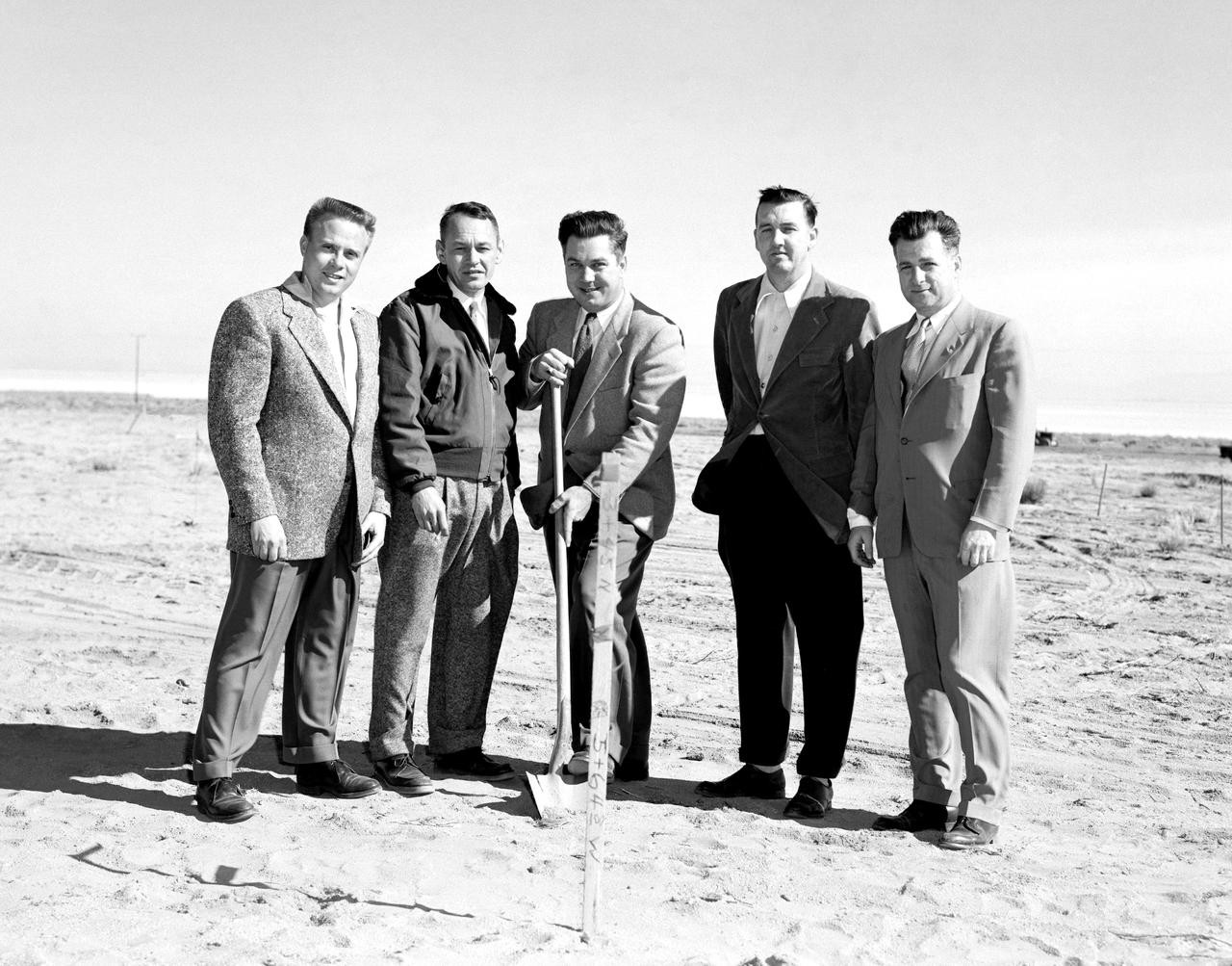
The NACA High-Speed Flight Research Station, had initially been subordinate to the Langley Memorial Aeronautical Laboratory near Hampton, Virginia, but as the flight research in the Mojave Desert increasingly proved its worth after 1946, it made sense to make the Flight Research Station a separate entity reporting directly to the headquarters of the National Advisory Committee for Aeronautics. But an autonomous center required all the trappings of a major research facility, including good quarters. With the adoption of the Edwards “Master Plan,” the Air Force had committed itself to moving from its old South Base to a new location midway between the South and North Bases. The NACA would have to move also--so why not take advantage of the situation and move into a full-blown research facility. The Air Force issued a lease to NACA for a location on the northwestern shore of the Roger Dry Lake. Construction started on the NACA station in early February 1953. On a windy day, January 27, 1953, at a groundbreaking ceremony stood left to right: Gerald Truszynski, Head of Instrumentation Division; Joseph Vensel, Head of the Operations Branch; Walter Williams, Head of the Station, scooping the first shovel full of dirt; Marion Kent, Head of Personnel; and California state official Arthur Samet.
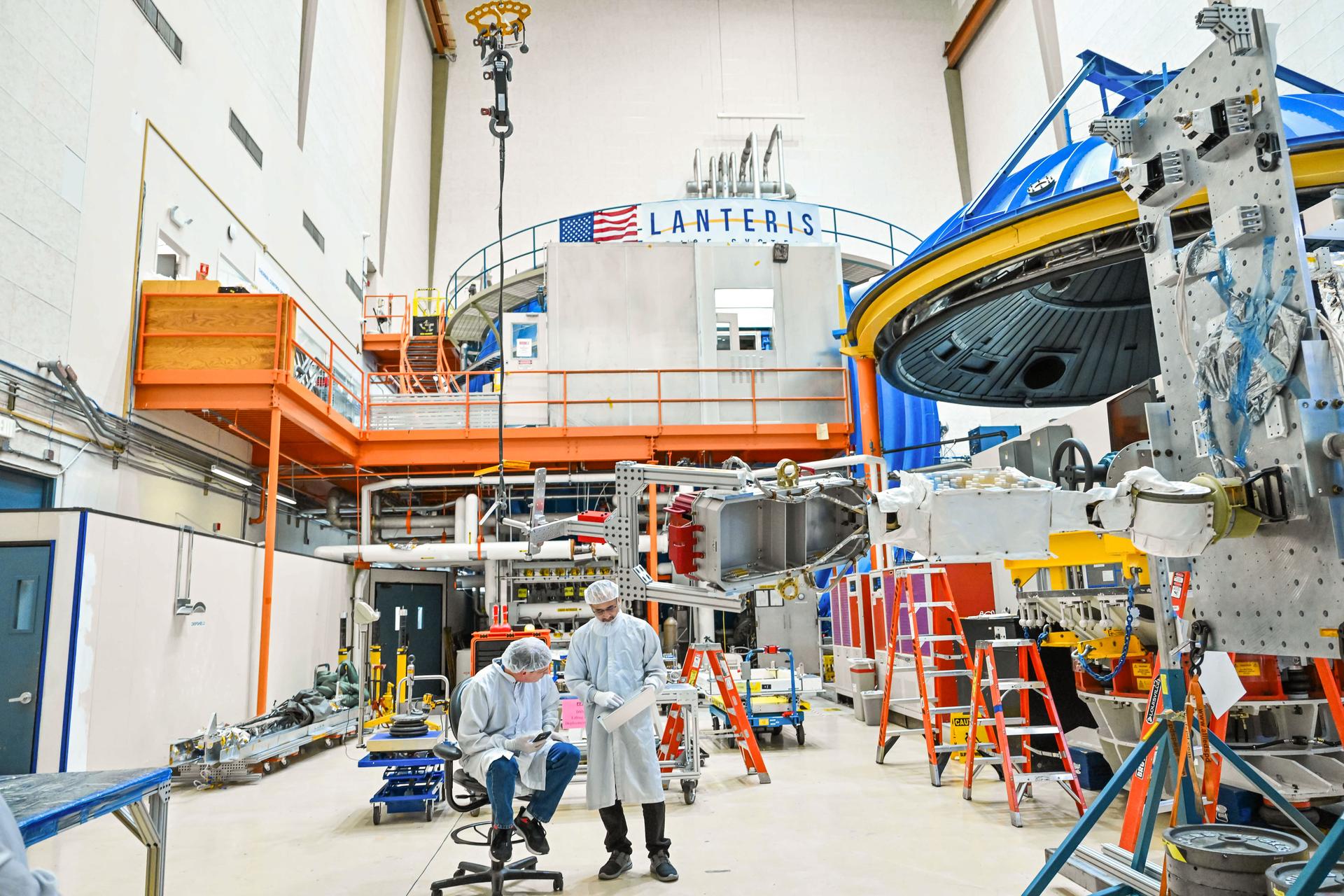
During this Engineering Qualification Module test, the gimbal platforms for the Busek-built BHT-6000 Hall effect thrusters are exercised through their full range of motion to verify articulation performance and confirm the system can properly steer thrust once integrated with Gateway’s Power and Propulsion Element (PPE). On PPE, four BHT-6000 Hall effect thrusters and three Advanced Electric Propulsion System (AEPS) thrusters will use solar power generated by Gateway’s Roll-Out Solar Arrays (ROSAs) to ionize xenon gas. The resulting xenon ions are then accelerated to extremely high speeds and expelled from the thrusters, creating a steady and highly efficient stream of thrust. This propulsion system will enable the Gateway lunar space station to maneuver and maintain its orbit around the Moon.
KENNEDY SPACE CENTER, FLA. -- In the cockpit of the orbiter Atlantis, which is in the Orbiter Processing Facility, U.S. Rep. Dave Weldon (right) looks at the newly installed Multifunction Electronic Display Subsystem (MEDS), known as the "glass cockpit." At left is Laural Patrick, a systems engineer with MEDS. Weldon is on the House Science Committee and vice chairman of the Space and Aeronautics Subcommittee. He was in Palmdale, Calif., when Atlantis underwent the modification and he wanted to see the final product. The full-color, flat-panel MEDS upgrade improves crew/orbiter interaction with easy-to-read, graphic portrayals of key flight indicators like attitude display and mach speed. The installation makes Atlantis the most modern orbiter in the fleet and equals the systems on current commercial jet airliners and military aircraft. Atlantis is scheduled to fly on mission STS-101 in early December
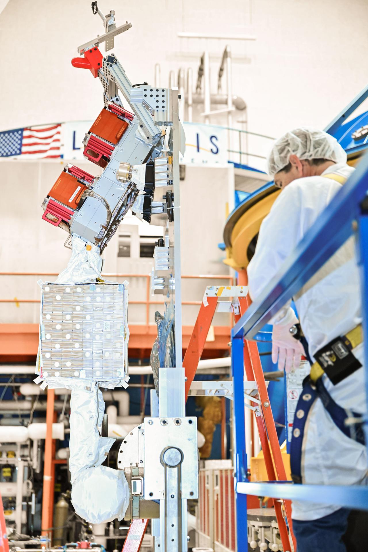
During this Engineering Qualification Module test, the gimbal platforms for the Busek-built BHT-6000 Hall effect thrusters are exercised through their full range of motion to verify articulation performance and confirm the system can properly steer thrust once integrated with Gateway’s Power and Propulsion Element (PPE). On PPE, four BHT-6000 Hall effect thrusters and three Advanced Electric Propulsion System (AEPS) thrusters will use solar power generated by Gateway’s Roll-Out Solar Arrays (ROSAs) to ionize xenon gas. The resulting xenon ions are then accelerated to extremely high speeds and expelled from the thrusters, creating a steady and highly efficient stream of thrust. This propulsion system will enable the Gateway lunar space station to maneuver and maintain its orbit around the Moon.
KENNEDY SPACE CENTER, FLA. -- Inside the orbiter Atlantis, Center Director Roy Bridges (seated at bottom left) and Associate Director for Advanced Development and Shuttle Upgrades JoAnn Morgan (standing second from left) learn about the new Multifunction Electronic Display Subsystem (MEDS) from Laural Patrick (standing left), a systems engineer with MEDS, and George Selina (at right), with United Space Alliance. Also called the "glass cockpit," the new full-color flat panel MEDS upgrade improves crew/orbiter interaction with easy-to-read, graphic portrayals of key flight indicators like attitude display and mach speed. The installation makes Atlantis the most modern orbiter in the fleet and equals the systems on current commercial jet airliners and military aircraft. Atlantis is scheduled to fly on mission STS-101 in early December

STS-101 Commander James Halsell (left) and STS-98 Commander Ken Cockrell (right) look over the recently installed Multifunction Electronic Display Subsystem (MEDS) in the cockpit of the orbiter Atlantis, which each will command on their upcoming respective missions. The new full-color, flat panel MEDS improves crew/orbiter interaction with easy-to-read, graphic portrayals of key flight indicators like attitude display and mach speed. The installation makes Atlantis the most modern orbiter in the fleet and equals the systems on current commercial jet airliners and military aircraft. . The first flight of the upgraded Atlantis is STS-101, scheduled for launch in December 1999; the second flight, STS-98, is scheduled for launch in April 2000
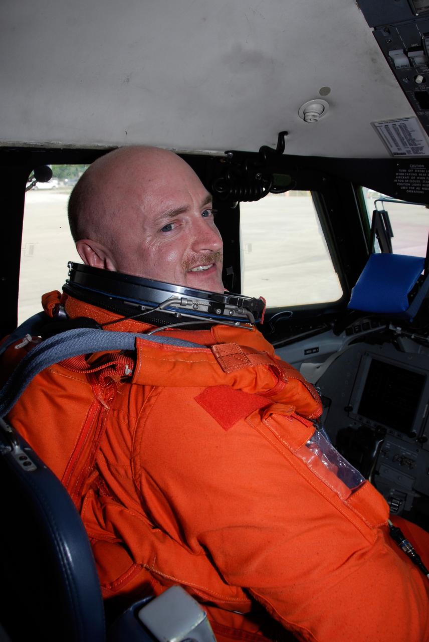
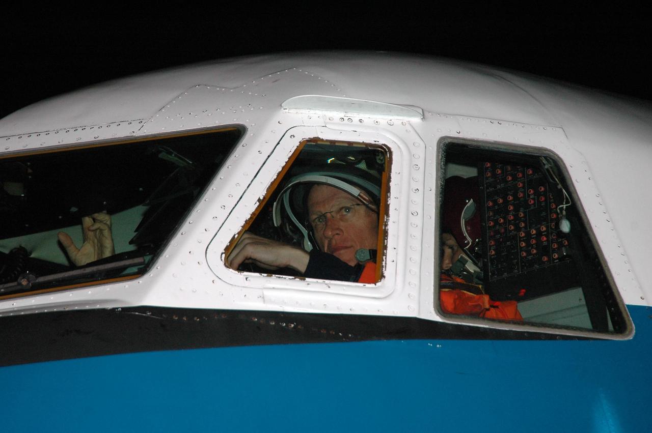
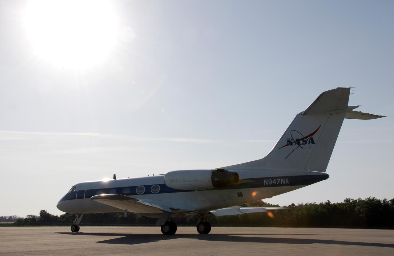
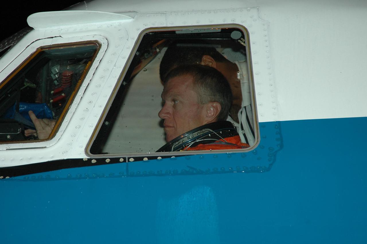
CAPE CANAVERAL, Fla. -- STS-124 Commander Mark Kelly sits in the cockpit of NASA's Shuttle Training Aircraft, or STA, preparing to practice space shuttle landings. The STA is a Grumman American Aviation-built Gulf Stream II jet that was modified to simulate an orbiter's cockpit, motion and visual cues, and handling qualities. In flight, the STA duplicates the orbiter's atmospheric descent trajectory from approximately 35,000 feet altitude to landing on a runway. Because the orbiter is unpowered during re-entry and landing, its high-speed glide must be perfectly executed the first time. The crew for space shuttle Discovery's STS-124 mission is at Kennedy for a full launch dress rehearsal, known as the terminal countdown demonstration test, or TCDT. Providing astronauts and ground crews with an opportunity to participate in various simulated countdown activities, TCDT includes equipment familiarization and emergency training. Discovery's launch is targeted for May 31. Photo credit: NASA/Kim Shiflett
KENNEDY SPACE CENTER, FLA. -- In the cockpit of the orbiter Atlantis, which is in the Orbiter Processing Facility, Laural Patrick (left), a systems engineer with MEDS, points out a feature of the newly installed Multifunction Electronic Display Subsystem (MEDS), known as the "glass cockpit," to U.S. Rep. Dave Weldon. The congressman is on the House Science Committee and vice chairman of the Space and Aeronautics Subcommittee. He was in Palmdale, Calif., when Atlantis underwent the modification and he wanted to see the final product. The full-color, flat-panel MEDS upgrade improves crew/orbiter interaction with easy-to-read, graphic portrayals of key flight indicators like attitude display and mach speed. The installation makes Atlantis the most modern orbiter in the fleet and equals the systems on current commercial jet airliners and military aircraft. Atlantis is scheduled to fly on mission STS-101 in early December
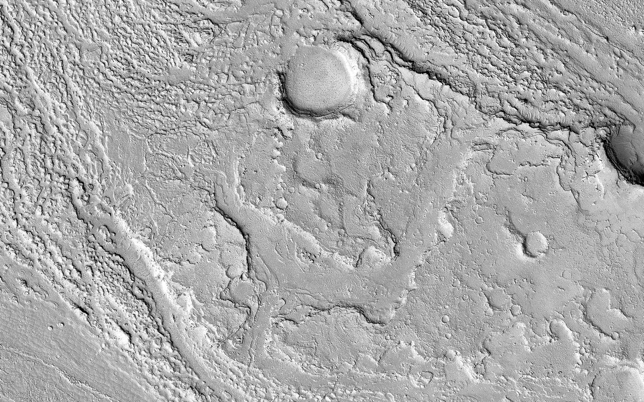
This image in Athabasca Valles shows lava flows originating from Elysium Mons to the northwest. A Context Camera image shows the lava flowed from the northwest to the southeast, diverting around obstacles as it settled. (The flow is outlined in blue with the flow direction shown in yellow, and the approximate location of the HiRISE image is represented by a white rectangle.) The lava appears to have flowed smoothly around obstructions, almost like water, forming streamlined islands. In the southern part of this image, a branch of the flow diverts around a small crater, and eventually rejoins the main part of the flow. Irregular-shaped ring structures appear on the northern end and are related to the volcanic activity that formed the flows. We also see a dense cluster of secondary craters that formed when material ejected from Corinto Crater (to the northwest) impacted the surface at high speed. At full-resolution, this terrain has the distinctive appearance of a field of numerous, small and closely-spaced craters. https://photojournal.jpl.nasa.gov/catalog/PIA23062
During this Engineering Qualification Module test, the gimbal platforms for the Busek-built BHT-6000 Hall effect thrusters are exercised through their full range of motion to verify articulation performance and confirm the system can properly steer thrust once integrated with Gateway’s Power and Propulsion Element (PPE). On PPE, four BHT-6000 Hall effect thrusters and three Advanced Electric Propulsion System (AEPS) thrusters will use solar power generated by Gateway’s Roll-Out Solar Arrays (ROSAs) to ionize xenon gas. The resulting xenon ions are then accelerated to extremely high speeds and expelled from the thrusters, creating a steady and highly efficient stream of thrust. This propulsion system will enable the Gateway lunar space station to maneuver and maintain its orbit around the Moon.
KENNEDY SPACE CENTER, FLA. -- In the cockpit of the orbiter Atlantis, which is in the Orbiter Processing Facility, U.S. Rep. Dave Weldon looks at the newly installed Multifunction Electronic Display Subsystem (MEDS), known as the "glass cockpit." Weldon is on the House Science Committee and vice chairman of the Space and Aeronautics Subcommittee. He was in Palmdale, Calif., when Atlantis underwent the modification and he wanted to see the final product. The full-color, flat-panel MEDS upgrade improves crew/orbiter interaction with easy-to-read, graphic portrayals of key flight indicators like attitude display and mach speed. The installation makes Atlantis the most modern orbiter in the fleet and equals the systems on current commercial jet airliners and military aircraft. Atlantis is scheduled to fly on mission STS-101 in early December
KENNEDY SPACE CENTER, FLA. - On NASA Kennedy Space Center's Shuttle Landing Facility, the Shuttle Training Aircraft taxis onto the runway. In the specially configured aircraft, STS-115 Commander Brent Jett and Pilot Christopher Ferguson will practice landing the shuttle. STA practice is part of launch preparations. The STA is a Grumman American Aviation-built Gulf Stream II jet that was modified to simulate an orbiter’s cockpit, motion and visual cues, and handling qualities. In flight, the STA duplicates the orbiter’s atmospheric descent trajectory from approximately 35,000 feet altitude to landing on a runway. Because the orbiter is unpowered during re-entry and landing, its high-speed glide must be perfectly executed the first time. Mission STS-115 is scheduled to lift off about 4:30 p.m. Aug. 27. The crew will deliver and install the P3/P4 segment to the port side of the integrated truss system on the International Space Station. The truss includes a new set of photovoltaic solar arrays. When unfurled to their full length of 240 feet, the arrays will provide additional power for the station in preparation for the delivery of international science modules over the next two years. The mission is expected to last 11 days and includes three scheduled spacewalks. Photo credit: NASA/Kim Shiflett
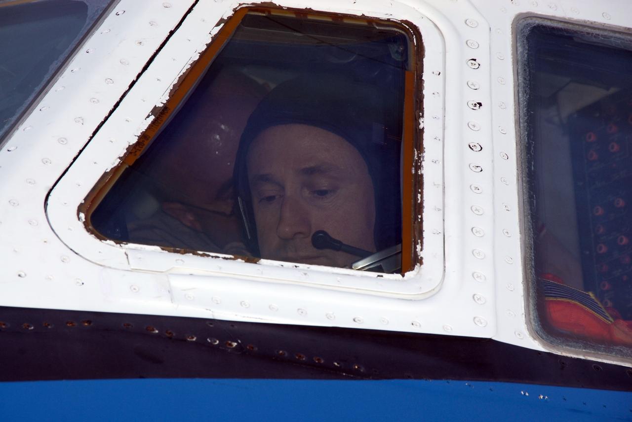
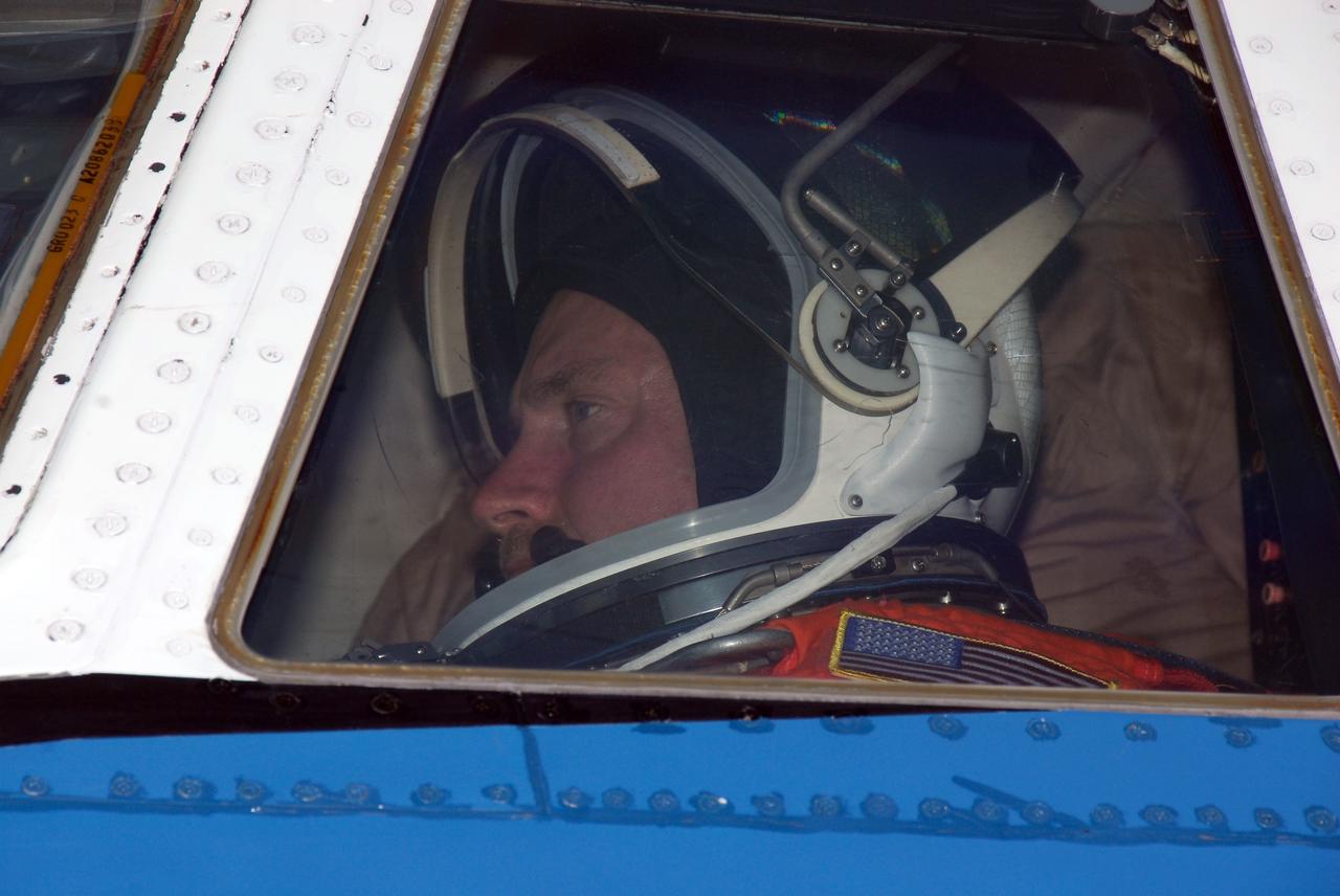
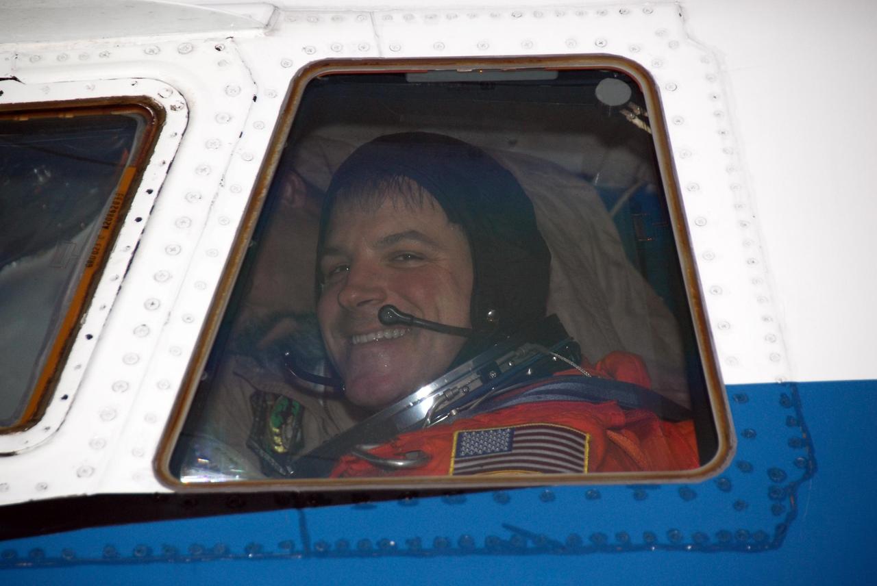
CAPE CANAVERAL, Fla. -- STS-124 Pilot Ken Ham is seen through the cockpit window of NASA's Shuttle Training Aircraft, or STA, before taxiing to the runway at the NASA Kennedy Space Center Shuttle Landing Facility to practice space shuttle landings. The STA is a Grumman American Aviation-built Gulf Stream II jet that was modified to simulate an orbiter's cockpit, motion and visual cues, and handling qualities. In flight, the STA duplicates the orbiter's atmospheric descent trajectory from approximately 35,000 feet altitude to landing on a runway. Because the orbiter is unpowered during re-entry and landing, its high-speed glide must be perfectly executed the first time. The crew for space shuttle Discovery's STS-124 mission is at Kennedy for a full launch dress rehearsal, known as the terminal countdown demonstration test, or TCDT. Providing astronauts and ground crews with an opportunity to participate in various simulated countdown activities, TCDT includes equipment familiarization and emergency training. Discovery's launch is targeted for May 31. Photo credit: NASA/Kim Shiflett
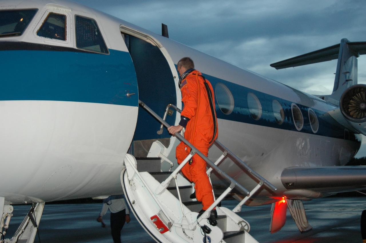
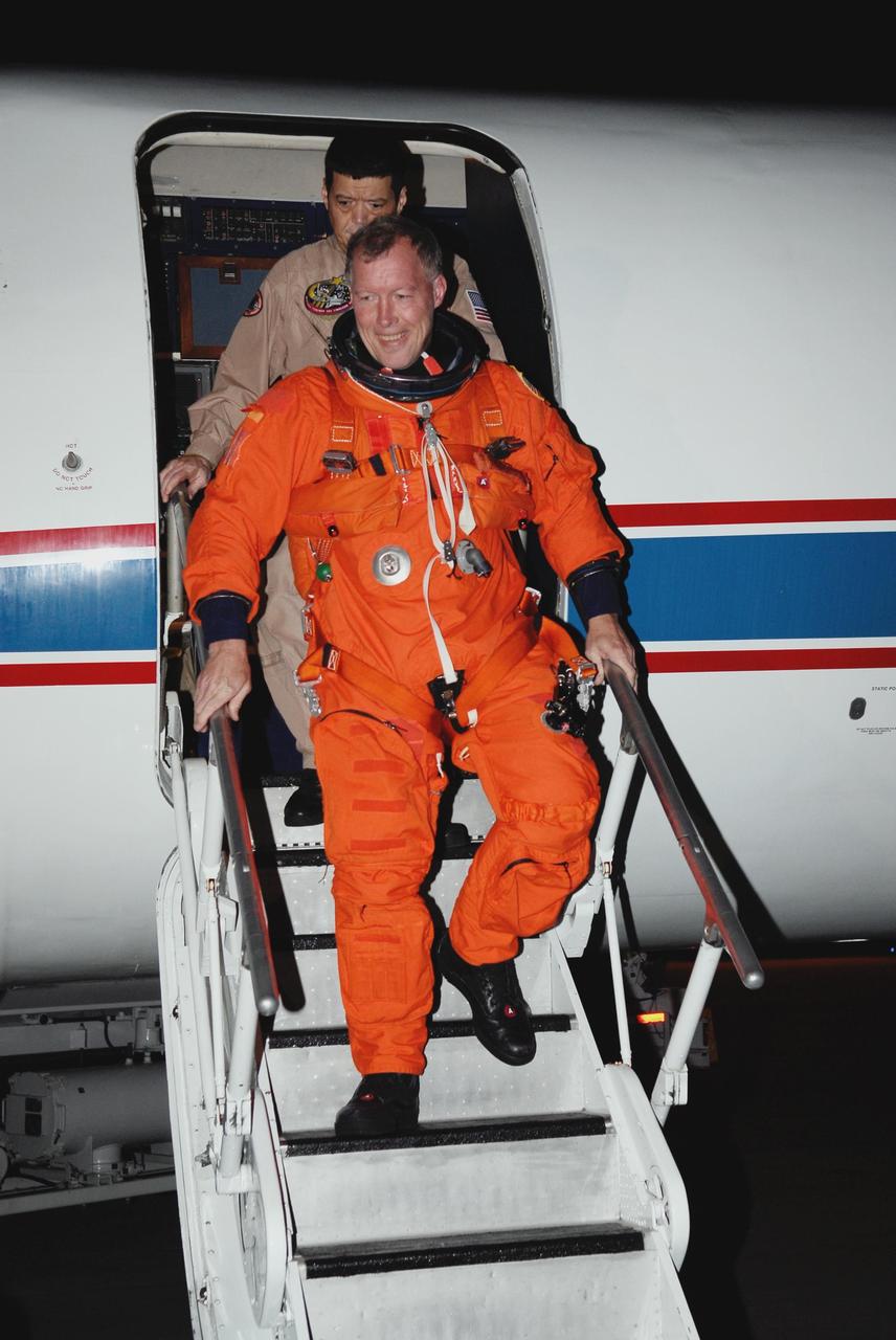
KENNEDY SPACE CENTER, FLA. - On NASA Kennedy Space Center's Shuttle Landing Facility, STS-115 Commander Brent Jett boards the Shuttle Training Aircraft to practice landing the shuttle. STA practice is part of launch preparations. The STA is a Grumman American Aviation-built Gulf Stream II jet that was modified to simulate an orbiter’s cockpit, motion and visual cues, and handling qualities. In flight, the STA duplicates the orbiter’s atmospheric descent trajectory from approximately 35,000 feet altitude to landing on a runway. Because the orbiter is unpowered during re-entry and landing, its high-speed glide must be perfectly executed the first time. Mission STS-115 is scheduled to lift off about 4:30 p.m. Aug. 27. The crew will deliver and install the P3/P4 segment to the port side of the integrated truss system on the International Space Station. The truss includes a new set of photovoltaic solar arrays. When unfurled to their full length of 240 feet, the arrays will provide additional power for the station in preparation for the delivery of international science modules over the next two years. The mission is expected to last 11 days and includes three scheduled spacewalks. Photo credit: NASA/Kim Shiflett

STS097-355-011 (30 Nov. -11 Dec. 2000) --- This vertical scene showing Torino and Milano, Italy, at night, was photographed with a 35mm camera by one of the STS-97 crew members aboard the Earth-orbiting Space Shuttle Endeavour. The night lights of Torino and Milano (two larger illuminated areas) are visible in the view, which covers the western end of the Po River Valley. Torino is the bright spot slightly left of center and Milano is the larger bright spot towards the bottom center of the image. The deeply eroded flanks of the snow-covered Alps Mountains (serrated-looking, light-colored terrain top half of the image) is visible north of the two large cities. Several mountain passes that connect the Po River Valley with France and Switzerland can be identified by the string of lights in the narrow, linear valleys. A translucent-looking cloud (bottom center) somewhat obscures the nighttime landscape south of Torino and Milano. The northwest coast of Italy, including the Italian city of Genova, can be identified in the lower left corner of the image. This photography was taken by astronauts using high speed film and long exposure on a night with a full moon illuminating the surface of the Earth.
CAPE CANAVERAL, Fla. -- STS-124 Commander Mark Kelly is seen through the cockpit window of NASA's Shuttle Training Aircraft, or STA, before taxiing to the runway at the NASA Kennedy Space Center Shuttle Landing Facility to practice space shuttle landings. The STA is a Grumman American Aviation-built Gulf Stream II jet that was modified to simulate an orbiter's cockpit, motion and visual cues, and handling qualities. In flight, the STA duplicates the orbiter's atmospheric descent trajectory from approximately 35,000 feet altitude to landing on a runway. Because the orbiter is unpowered during re-entry and landing, its high-speed glide must be perfectly executed the first time. The crew for space shuttle Discovery's STS-124 mission is at Kennedy for a full launch dress rehearsal, known as the terminal countdown demonstration test, or TCDT. Providing astronauts and ground crews with an opportunity to participate in various simulated countdown activities, TCDT includes equipment familiarization and emergency training. Discovery's launch is targeted for May 31. Photo credit: NASA/Kim Shiflett
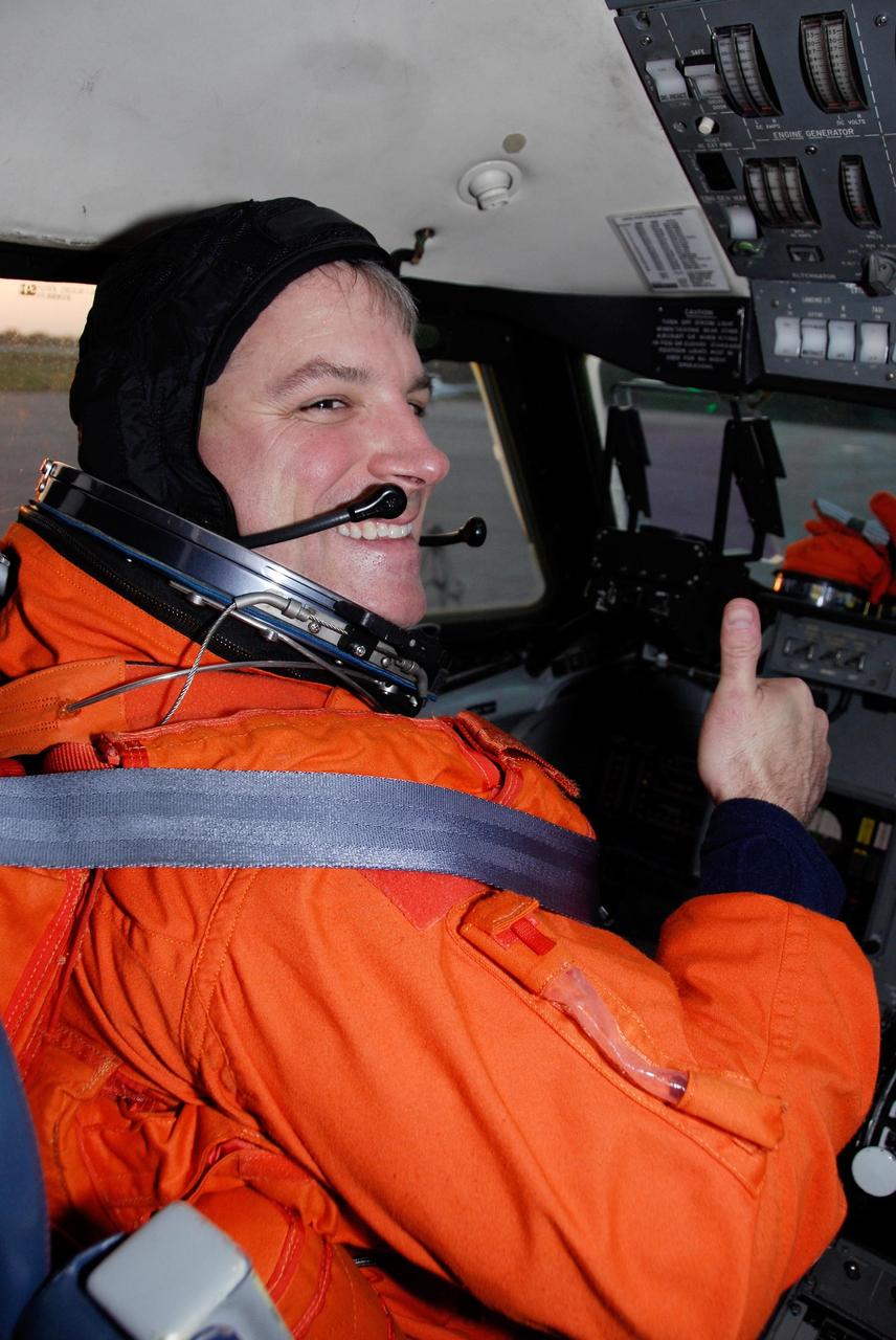
KENNEDY SPACE CENTER, FLA. - STS-115 Pilot Christopher Ferguson settles in the cockpit of the Shuttle Training Aircraft to practice landing the shuttle. STA practice is part of launch preparations. The STA is a Grumman American Aviation-built Gulf Stream II jet that was modified to simulate an orbiter’s cockpit, motion and visual cues, and handling qualities. In flight, the STA duplicates the orbiter’s atmospheric descent trajectory from approximately 35,000 feet altitude to landing on a runway. Because the orbiter is unpowered during re-entry and landing, its high-speed glide must be perfectly executed the first time. Mission STS-115 is scheduled to lift off about 4:30 p.m. Aug. 27. The crew will deliver and install the P3/P4 segment to the port side of the integrated truss system on the International Space Station. The truss includes a new set of photovoltaic solar arrays. When unfurled to their full length of 240 feet, the arrays will provide additional power for the station in preparation for the delivery of international science modules over the next two years. The mission is expected to last 11 days and includes three scheduled spacewalks. Photo credit: NASA/Kim Shiflett
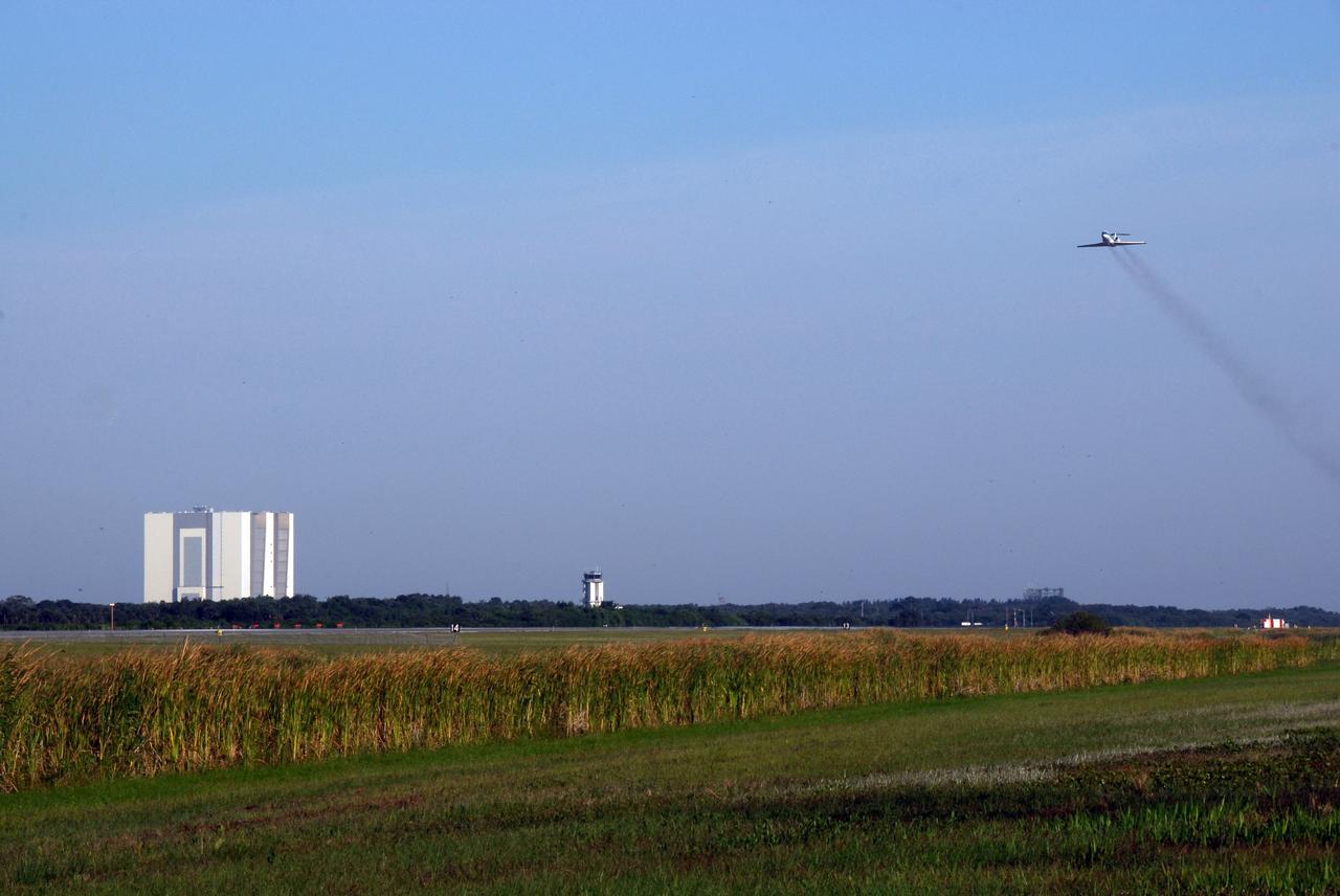
CAPE CANAVERAL, Fla. -- NASA's Shuttle Training Aircraft, or STA, soars into the sky (at right) over the NASA Kennedy Space Center Shuttle Landing Facility. At the controls is either STS-124 Commander Mark Kelly or Pilot Ken Ham, who are practicing space shuttle landings. At left, in the background, is the Vehicle Assembly Building. The STA is a Grumman American Aviation-built Gulf Stream II jet that was modified to simulate an orbiter's cockpit, motion and visual cues, and handling qualities. In flight, the STA duplicates the orbiter's atmospheric descent trajectory from approximately 35,000 feet altitude to landing on a runway. Because the orbiter is unpowered during re-entry and landing, its high-speed glide must be perfectly executed the first time. The crew for space shuttle Discovery's STS-124 mission is at Kennedy for a full launch dress rehearsal, known as the terminal countdown demonstration test, or TCDT. Providing astronauts and ground crews with an opportunity to participate in various simulated countdown activities, TCDT includes equipment familiarization and emergency training. Discovery's launch is targeted for May 31. Photo credit: NASA/Kim Shiflett
KENNEDY SPACE CENTER, FLA. - STS-115 Pilot Christopher Ferguson settles in the cockpit of the Shuttle Training Aircraft to practice landing the shuttle. STA practice is part of launch preparations. The STA is a Grumman American Aviation-built Gulf Stream II jet that was modified to simulate an orbiter’s cockpit, motion and visual cues, and handling qualities. In flight, the STA duplicates the orbiter’s atmospheric descent trajectory from approximately 35,000 feet altitude to landing on a runway. Because the orbiter is unpowered during re-entry and landing, its high-speed glide must be perfectly executed the first time. Mission STS-115 is scheduled to lift off about 12:29 p.m. Sept. 6. Mission managers cancelled Atlantis' first launch campaign due to a lightning strike at the pad and the passage of Tropical Storm Ernesto along Florida's east coast. The mission will deliver and install the 17-and-a-half-ton P3/P4 truss segment to the port side of the integrated truss system on the orbital outpost. The truss includes a new set of photovoltaic solar arrays. When unfurled to their full length of 240 feet, the arrays will provide additional power for the station in preparation for the delivery of international science modules over the next two years. STS-115 is expected to last 11 days and includes three scheduled spacewalks. Photo credit: NASA/Kim Shiflett
CAPE CANAVERAL, Fla. -- NASA's Shuttle Training Aircraft, or STA, soars into the blue Florida sky to begin the space shuttle landing practice. STS-124 Commander Mark Kelly or Pilot Ken Ham is at the controls. The STA is a Grumman American Aviation-built Gulf Stream II jet that was modified to simulate an orbiter's cockpit, motion and visual cues, and handling qualities. In flight, the STA duplicates the orbiter's atmospheric descent trajectory from approximately 35,000 feet altitude to landing on a runway. Because the orbiter is unpowered during re-entry and landing, its high-speed glide must be perfectly executed the first time. The crew for space shuttle Discovery's STS-124 mission is at Kennedy for a full launch dress rehearsal, known as the terminal countdown demonstration test, or TCDT. Providing astronauts and ground crews with an opportunity to participate in various simulated countdown activities, TCDT includes equipment familiarization and emergency training. Discovery's launch is targeted for May 31. Photo credit: NASA/Kim Shiflett
CAPE CANAVERAL, Fla. -- STS-124 Pilot Ken Ham takes his seat in the cockpit of NASA's Shuttle Training Aircraft, or STA, preparing to practice space shuttle landings. The STA is a Grumman American Aviation-built Gulf Stream II jet that was modified to simulate an orbiter's cockpit, motion and visual cues, and handling qualities. In flight, the STA duplicates the orbiter's atmospheric descent trajectory from approximately 35,000 feet altitude to landing on a runway. Because the orbiter is unpowered during re-entry and landing, its high-speed glide must be perfectly executed the first time. The crew for space shuttle Discovery's STS-124 mission is at Kennedy for a full launch dress rehearsal, known as the terminal countdown demonstration test, or TCDT. Providing astronauts and ground crews with an opportunity to participate in various simulated countdown activities, TCDT includes equipment familiarization and emergency training. Discovery's launch is targeted for May 31. Photo credit: NASA/Kim Shiflett
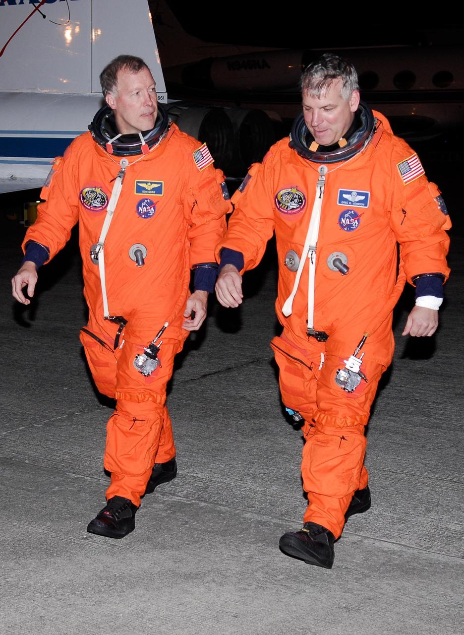
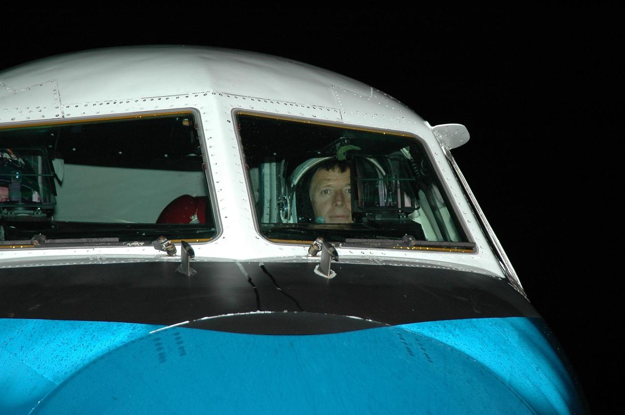
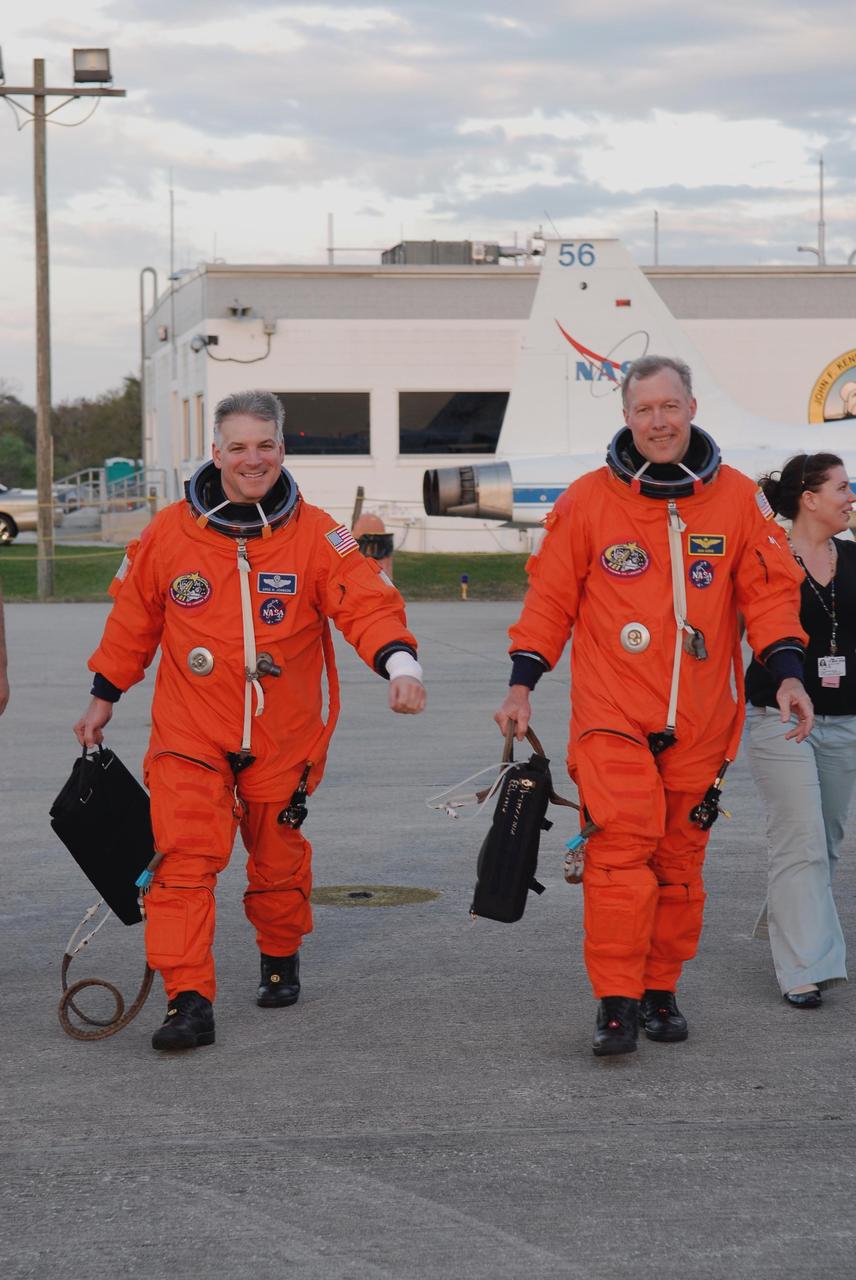
KENNEDY SPACE CENTER, FLA. -- At NASA Kennedy Space Center's Shuttle Landing Facility, STS-123 Commander Dominic Gorie , left, and Pilot Gregory H. Johnson head for crew quarters following a practice session of space shuttle landings aboard NASA's Shuttle Training Aircraft, or STAs. The STA is a Grumman American Aviation-built Gulf Stream II jet that was modified to simulate an orbiter's cockpit, motion and visual cues, and handling qualities. In flight, the STA duplicates the orbiter's atmospheric descent trajectory from approximately 35,000 feet altitude to landing on a runway. Because the orbiter is unpowered during re-entry and landing, its high-speed glide must be perfectly executed the first time. The crew for space shuttle Endeavour's STS-123 mission is at Kennedy for a full launch dress rehearsal, known as the terminal countdown demonstration test or TCDT. The terminal countdown demonstration test provides astronauts and ground crews with an opportunity to participate in various simulated countdown activities, including equipment familiarization and emergency training. Endeavour is targeted to launch March 11 at 2:28 a.m. EDT on a 16-day mission to the International Space Station. On the mission, Endeavour and its crew will deliver the first section of the Japan Aerospace Exploration Agency's Kibo laboratory and the Canadian Space Agency's two-armed robotic system, Dextre. Photo credit: NASA/Kim Shiflett
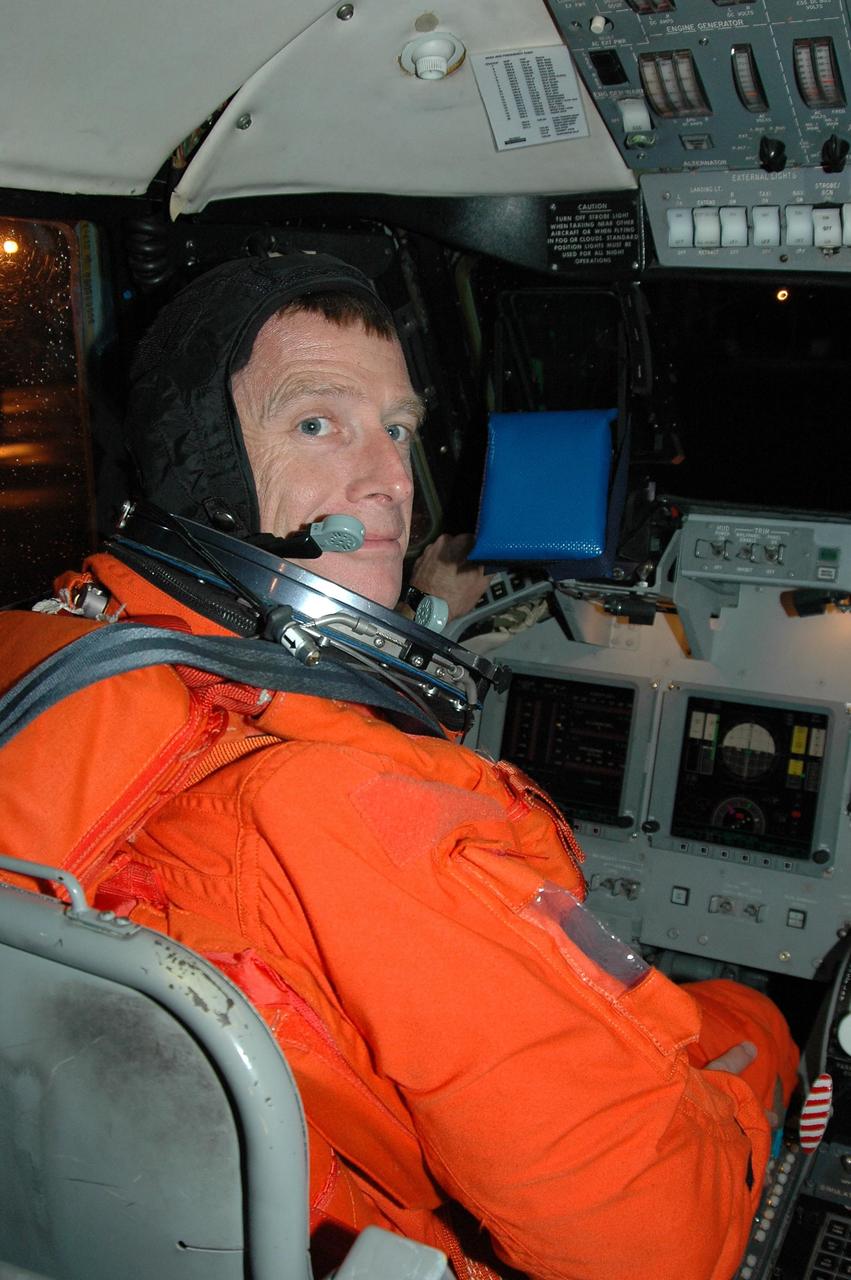
KENNEDY SPACE CENTER, FLA. - STS-115 Commander Brent Jett is seen at the controls of the Shuttle Training Aircraft which he will fly to practice landing the shuttle. STA practice is part of launch preparations. The STA is a Grumman American Aviation-built Gulf Stream II jet that was modified to simulate an orbiter’s cockpit, motion and visual cues, and handling qualities. In flight, the STA duplicates the orbiter’s atmospheric descent trajectory from approximately 35,000 feet altitude to landing on a runway. Because the orbiter is unpowered during re-entry and landing, its high-speed glide must be perfectly executed the first time. Mission STS-115 is scheduled to lift off about 4:30 p.m. Aug. 27. The crew will deliver and install the P3/P4 segment to the port side of the integrated truss system on the International Space Station. The truss includes a new set of photovoltaic solar arrays. When unfurled to their full length of 240 feet, the arrays will provide additional power for the station in preparation for the delivery of international science modules over the next two years. The mission is expected to last 11 days and includes three scheduled spacewalks. Photo credit: NASA/Kim Shiflett
The resolution of the Boeing B-29 Superfortress’ engine cooling problems was one of the Aircraft Engine Research Laboratory’s (AERL) key contributions to the World War II effort. The B-29 leapfrogged previous bombers in size, speed, and altitude capabilities. The B–29 was intended to soar above anti-aircraft fire and make pinpoint bomb drops onto strategic targets. Four Wright Aeronautical R-3350 engines powered the massive aircraft. The engines, however, frequently strained and overheated due to payload overloading. This resulted in a growing number of engine fires that often resulted in crashes. The military asked the NACA to tackle the overheating issue. Full-scale engine tests on a R–3350 engine in the Prop House demonstrated that a NACA-designed impeller increased the fuel injection system’s flow rate. Single-cylinder studies resolved a valve failure problem by a slight extension of the cylinder head, and researchers in the Engine Research Building combated uneven heating with a new fuel injection system. Investigations during the summer of 1944 in the Altitude Wind Tunnel, which could simulate flight conditions at high altitudes, led to reduction of drag and improved air flow by reshaping the cowling inlet and outlet. The NACA modifications were then flight tested on a B-29 bomber that was brought to the AERL.
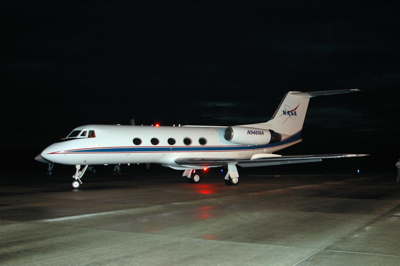
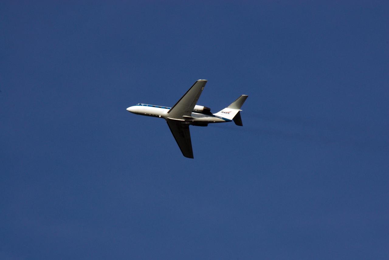
KENNEDY SPACE CENTER, FLA. -- At NASA Kennedy Space Center's Shuttle Landing Facility, a Shuttle Training Aircraft, or STA, is preparing to take off for practice space shuttle landings. The STA is a Grumman American Aviation-built Gulf Stream II jet that was modified to simulate an orbiter's cockpit, motion and visual cues, and handling qualities. In flight, the STA duplicates the orbiter's atmospheric descent trajectory from approximately 35,000 feet altitude to landing on a runway. Because the orbiter is unpowered during re-entry and landing, its high-speed glide must be perfectly executed the first time. The crew for space shuttle Endeavour's STS-123 mission is at Kennedy for a full launch dress rehearsal, known as the terminal countdown demonstration test or TCDT. The terminal countdown demonstration test provides astronauts and ground crews with an opportunity to participate in various simulated countdown activities, including equipment familiarization and emergency training. Endeavour is targeted to launch March 11 at 2:28 a.m. EDT on a 16-day mission to the International Space Station. On the mission, Endeavour and its crew will deliver the first section of the Japan Aerospace Exploration Agency's Kibo laboratory and the Canadian Space Agency's two-armed robotic system, Dextre. Photo credit: NASA/Kim Shiflett
KENNEDY SPACE CENTER, FLA. -- At NASA Kennedy Space Center's Shuttle Landing Facility, STS-123 Pilot Gregory H. Johnson boards a Shuttle Training Aircraft, or STA, to practice space shuttle landings. The STA is a Grumman American Aviation-built Gulf Stream II jet that was modified to simulate an orbiter's cockpit, motion and visual cues, and handling qualities. In flight, the STA duplicates the orbiter's atmospheric descent trajectory from approximately 35,000 feet altitude to landing on a runway. Because the orbiter is unpowered during re-entry and landing, its high-speed glide must be perfectly executed the first time. The crew for space shuttle Endeavour's STS-123 mission is at Kennedy for a full launch dress rehearsal, known as the terminal countdown demonstration test or TCDT. The terminal countdown demonstration test provides astronauts and ground crews with an opportunity to participate in various simulated countdown activities, including equipment familiarization and emergency training. Endeavour is targeted to launch March 11 at 2:28 a.m. EDT on a 16-day mission to the International Space Station. On the mission, Endeavour and its crew will deliver the first section of the Japan Aerospace Exploration Agency's Kibo laboratory and the Canadian Space Agency's two-armed robotic system, Dextre. Photo credit: NASA/Kim Shiflett
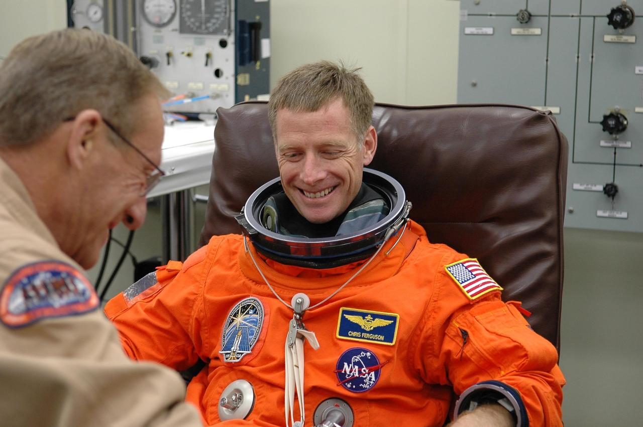
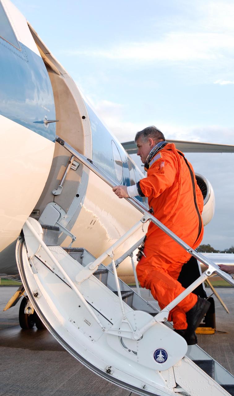
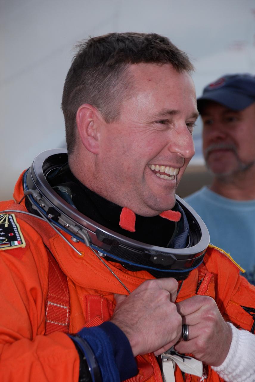
KENNEDY SPACE CENTER, FLA. - STS-115 Pilot Christopher Ferguson is helped donning his launch suit before flying the Shuttle Training Aircraft to practice landing the shuttle. STA practice is part of launch preparations. The STA is a Grumman American Aviation-built Gulf Stream II jet that was modified to simulate an orbiter’s cockpit, motion and visual cues, and handling qualities. In flight, the STA duplicates the orbiter’s atmospheric descent trajectory from approximately 35,000 feet altitude to landing on a runway. Because the orbiter is unpowered during re-entry and landing, its high-speed glide must be perfectly executed the first time. Mission STS-115 is scheduled to lift off about 4:30 p.m. Aug. 27. The crew will deliver and install the P3/P4 segment to the port side of the integrated truss system on the International Space Station. The truss includes a new set of photovoltaic solar arrays. When unfurled to their full length of 240 feet, the arrays will provide additional power for the station in preparation for the delivery of international science modules over the next two years. The mission is expected to last 11 days and includes three scheduled spacewalks. Photo credit: NASA/Kim Shiflett
KENNEDY SPACE CENTER, FLA. -- At NASA Kennedy Space Center's Shuttle Landing Facility, STS-123 Commander Dominic Gorie disembarks from a Shuttle Training Aircraft, or STA, following a practice session of space shuttle landings. The STA is a Grumman American Aviation-built Gulf Stream II jet that was modified to simulate an orbiter's cockpit, motion and visual cues, and handling qualities. In flight, the STA duplicates the orbiter's atmospheric descent trajectory from approximately 35,000 feet altitude to landing on a runway. Because the orbiter is unpowered during re-entry and landing, its high-speed glide must be perfectly executed the first time. The crew for space shuttle Endeavour's STS-123 mission is at Kennedy for a full launch dress rehearsal, known as the terminal countdown demonstration test or TCDT. The terminal countdown demonstration test provides astronauts and ground crews with an opportunity to participate in various simulated countdown activities, including equipment familiarization and emergency training. Endeavour is targeted to launch March 11 at 2:28 a.m. EDT on a 16-day mission to the International Space Station. On the mission, Endeavour and its crew will deliver the first section of the Japan Aerospace Exploration Agency's Kibo laboratory and the Canadian Space Agency's two-armed robotic system, Dextre. Photo credit: NASA/Kim Shiflett
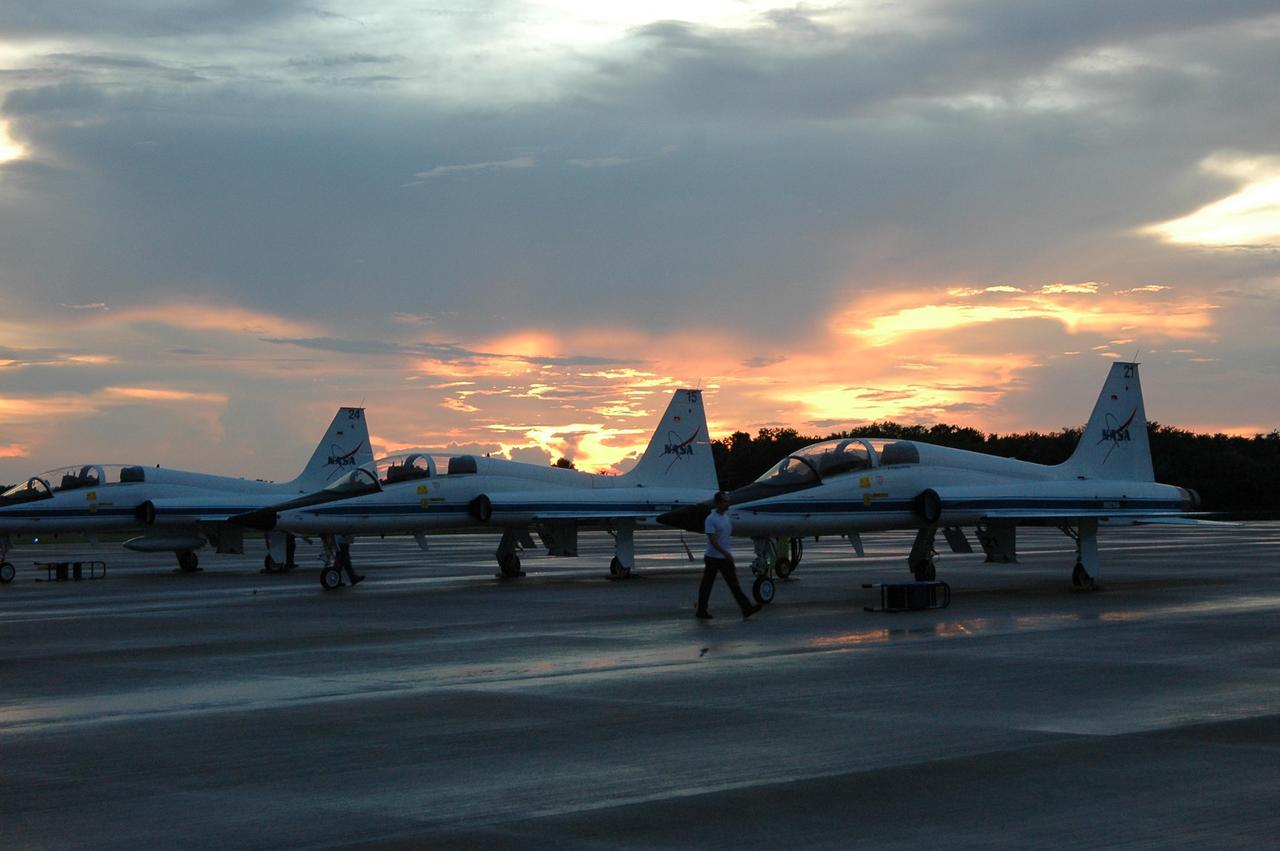
KENNEDY SPACE CENTER, FLA. - Under cloudy skies at sunset, T-38 jet aircraft are lined up on the NASA Kennedy Space Center's Shuttle Landing Facility where STS-115 Commander Brent Jett and Pilot Christopher Ferguson will be climbing aboard the Shuttle Training Aircraft to practice landing the shuttle. STA practice is part of launch preparations. The STA is a Grumman American Aviation-built Gulf Stream II jet that was modified to simulate an orbiter’s cockpit, motion and visual cues, and handling qualities. In flight, the STA duplicates the orbiter’s atmospheric descent trajectory from approximately 35,000 feet altitude to landing on a runway. Because the orbiter is unpowered during re-entry and landing, its high-speed glide must be perfectly executed the first time. Mission STS-115 is scheduled to lift off about 4:30 p.m. Aug. 27. The crew will deliver and install the P3/P4 segment to the port side of the integrated truss system on the International Space Station. The truss includes a new set of photovoltaic solar arrays. When unfurled to their full length of 240 feet, the arrays will provide additional power for the station in preparation for the delivery of international science modules over the next two years. The mission is expected to last 11 days and includes three scheduled spacewalks. Photo credit: NASA/Kim Shiflett
KENNEDY SPACE CENTER, FLA. -- At NASA Kennedy Space Center's Shuttle Landing Facility, STS-123 Pilot Gregory H. Johnson prepares for takeoff in a Shuttle Training Aircraft, or STA, to practice space shuttle landings. The STA is a Grumman American Aviation-built Gulf Stream II jet that was modified to simulate an orbiter's cockpit, motion and visual cues, and handling qualities. In flight, the STA duplicates the orbiter's atmospheric descent trajectory from approximately 35,000 feet altitude to landing on a runway. Because the orbiter is unpowered during re-entry and landing, its high-speed glide must be perfectly executed the first time. The crew for space shuttle Endeavour's STS-123 mission is at Kennedy for a full launch dress rehearsal, known as the terminal countdown demonstration test or TCDT. The terminal countdown demonstration test provides astronauts and ground crews with an opportunity to participate in various simulated countdown activities, including equipment familiarization and emergency training. Endeavour is targeted to launch March 11 at 2:28 a.m. EDT on a 16-day mission to the International Space Station. On the mission, Endeavour and its crew will deliver the first section of the Japan Aerospace Exploration Agency's Kibo laboratory and the Canadian Space Agency's two-armed robotic system, Dextre. Photo credit: NASA/Kim Shiflett
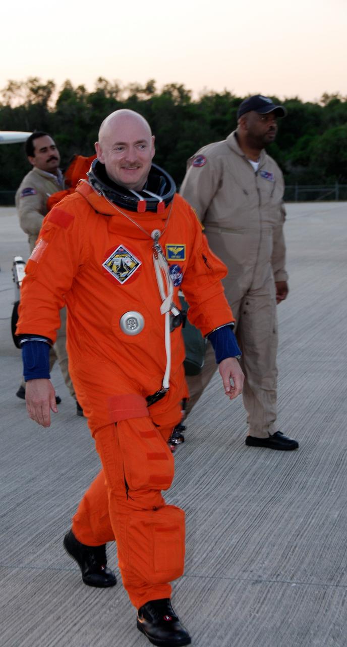
CAPE CANAVERAL, Fla. -- Back at the NASA Kennedy Space Center Shuttle Landing Facility, STS-124 Commander Mark Kelly happily crosses the parking area after the successful space shuttle landing practice aboard NASA's Shuttle Training Aircraft, or STA. The STA is a Grumman American Aviation-built Gulf Stream II jet that was modified to simulate an orbiter's cockpit, motion and visual cues, and handling qualities. In flight, the STA duplicates the orbiter's atmospheric descent trajectory from approximately 35,000 feet altitude to landing on a runway. Because the orbiter is unpowered during re-entry and landing, its high-speed glide must be perfectly executed the first time. The crew for space shuttle Discovery's STS-124 mission is at Kennedy for a full launch dress rehearsal, known as the terminal countdown demonstration test, or TCDT. Providing astronauts and ground crews with an opportunity to participate in various simulated countdown activities, TCDT includes equipment familiarization and emergency training. Discovery's launch is targeted for May 31. Photo credit: NASA/Kim Shiflett
KENNEDY SPACE CENTER, FLA. -- At NASA Kennedy Space Center's Shuttle Landing Facility, STS-123 Pilot Gregory H. Johnson disembarks from a Shuttle Training Aircraft, or STA, following a practice session of space shuttle landings. The STA is a Grumman American Aviation-built Gulf Stream II jet that was modified to simulate an orbiter's cockpit, motion and visual cues, and handling qualities. In flight, the STA duplicates the orbiter's atmospheric descent trajectory from approximately 35,000 feet altitude to landing on a runway. Because the orbiter is unpowered during re-entry and landing, its high-speed glide must be perfectly executed the first time. The crew for space shuttle Endeavour's STS-123 mission is at Kennedy for a full launch dress rehearsal, known as the terminal countdown demonstration test or TCDT. The terminal countdown demonstration test provides astronauts and ground crews with an opportunity to participate in various simulated countdown activities, including equipment familiarization and emergency training. Endeavour is targeted to launch March 11 at 2:28 a.m. EDT on a 16-day mission to the International Space Station. On the mission, Endeavour and its crew will deliver the first section of the Japan Aerospace Exploration Agency's Kibo laboratory and the Canadian Space Agency's two-armed robotic system, Dextre. Photo credit: NASA/Kim Shiflett

A Wright Aeronautical XRJ47-W-5 ramjet installed in a test chamber of the National Advisory Committee for Aeronautics’ (NACA) new Propulsion Systems Laboratory at the Lewis Flight Propulsion Laboratory. Construction of the facility had only recently been completed, and NACA engineers were still testing the various operating systems. The Propulsion Systems Laboratory was the NACA’s most powerful facility for testing full-scale engines in simulated flight altitudes. It contained two 14-foot diameter and 100-foot-long altitude chambers that ran parallel to one another with a control room in between. The engine being tested was installed inside the test section of one of the chambers, seen in this photograph. Extensive instrumentation was fitted onto the engine prior to the test. Once the chamber was sealed, the altitude conditions were introduced, and the engine was ignited. Operators in the control room could run the engine at the various speeds and adjust the altitude conditions to the desired levels. The engine’s exhaust was ejected into the cooling equipment. Two 48-inch diameter XRJ47-W-5 ramjets were used to power the North American Aviation Navaho Missile. The Navaho was a winged missile that was intended to travel up to 3000 miles carrying a nuclear warhead. It was launched using rocket booster engines that were ejected after the missile’s ramjet engines were ignited.
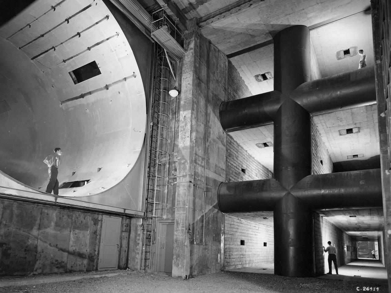
The 8- by 6-Foot Supersonic Wind Tunnel at the National Advisory Committee for Aeronautics (NACA) Lewis Flight Propulsion Laboratory was the largest supersonic wind tunnel in the nation at the time and the only one able to test full-scale engines at supersonic speeds. The 8- by 6 was designed as a non-return and open-throat tunnel. A large compressor created the air flow at one end of the tunnel, squeezed the flow to increase its velocity just before the test section, then reduced the velocity, and expelled it into the atmosphere at the other end of the tunnel. This design worked well for initial aerodynamic testing, but the local community was literally rattled by the noise and vibrations when researchers began running engines in the test section in January 1950. The NACA’s most modern wind tunnel was referred to as “an 87,000-horsepower bugle aimed at the heart of Cleveland.” NACA Lewis responded to the complaints by adding an acoustic housing at the end of the tunnel to dampen the noise. The structure included resonator chambers and a reinforced concrete muffler structure. Modifications continued over the years. A return leg was added, and a second test section, 9 -by 15-foot, was incorporated in the return leg in the 1960s. Since its initial operation in 1948, the 8- by 6-foot tunnel has been aggressively used to support the nation's aeronautics and space programs for the military, industry, and academia.
KENNEDY SPACE CENTER, FLA. -- At NASA Kennedy Space Center's Shuttle Landing Facility, STS-123 Pilot Gregory H. Johnson is seen through the window of a Shuttle Training Aircraft, or STA, as he prepares to practice space shuttle landings. The STA is a Grumman American Aviation-built Gulf Stream II jet that was modified to simulate an orbiter's cockpit, motion and visual cues, and handling qualities. In flight, the STA duplicates the orbiter's atmospheric descent trajectory from approximately 35,000 feet altitude to landing on a runway. Because the orbiter is unpowered during re-entry and landing, its high-speed glide must be perfectly executed the first time. The crew for space shuttle Endeavour's STS-123 mission is at Kennedy for a full launch dress rehearsal, known as the terminal countdown demonstration test or TCDT. The terminal countdown demonstration test provides astronauts and ground crews with an opportunity to participate in various simulated countdown activities, including equipment familiarization and emergency training. Endeavour is targeted to launch March 11 at 2:28 a.m. EDT on a 16-day mission to the International Space Station. On the mission, Endeavour and its crew will deliver the first section of the Japan Aerospace Exploration Agency's Kibo laboratory and the Canadian Space Agency's two-armed robotic system, Dextre. Photo credit: NASA/Kim Shiflett

Saturn's clouds are full of raw beauty, but they also represent a playground for a branch of physics called fluid dynamics, which seeks to understand the motion of gases and liquids. Saturn's lack of a solid planetary surface (as on Earth, Mars or Venus) means that its atmosphere is free to flow around the planet essentially without obstruction. This is one factor that generates Saturn's pattern of alternating belts and zones -- one of the main features of its dynamic atmosphere. Winds in the belts blow at speeds different from those in the adjacent zones, leading to the formation of vortices along the boundaries between the two. And vigorous convection occasionally leads to storms and waves. Saturn's innermost rings are just visible at the bottom and in the upper left corner. This view is centered on clouds at 25 degrees north latitude on Saturn. The image was taken with the Cassini spacecraft wide-angle camera on July 20, 2016 using a spectral filter which preferentially admits wavelengths of near-infrared light centered at 728 nanometers. The view was obtained at a distance of approximately 752,000 miles (1.21 million kilometers) from Saturn and at a Sun-Saturn-spacecraft, or phase, angle of 6 degrees. Image scale is 45 miles (72 kilometers) per pixel. http://photojournal.jpl.nasa.gov/catalog/PIA20503
KENNEDY SPACE CENTER, FLA. -- At NASA Kennedy Space Center's Shuttle Landing Facility, STS-123 Pilot Gregory H. Johnson, left, and Commander Dominic Gorie prepare to practice space shuttle landings using NASA's Shuttle Training Aircraft, or STA. The STA is a Grumman American Aviation-built Gulf Stream II jet that was modified to simulate an orbiter's cockpit, motion and visual cues, and handling qualities. In flight, the STA duplicates the orbiter's atmospheric descent trajectory from approximately 35,000 feet altitude to landing on a runway. Because the orbiter is unpowered during re-entry and landing, its high-speed glide must be perfectly executed the first time. The crew for space shuttle Endeavour's STS-123 mission is at Kennedy for a full launch dress rehearsal, known as the terminal countdown demonstration test or TCDT. The terminal countdown demonstration test provides astronauts and ground crews with an opportunity to participate in various simulated countdown activities, including equipment familiarization and emergency training. Endeavour is targeted to launch March 11 at 2:28 a.m. EDT on a 16-day mission to the International Space Station. On the mission, Endeavour and its crew will deliver the first section of the Japan Aerospace Exploration Agency's Kibo laboratory and the Canadian Space Agency's two-armed robotic system, Dextre. Photo credit: NASA/Kim Shiflett
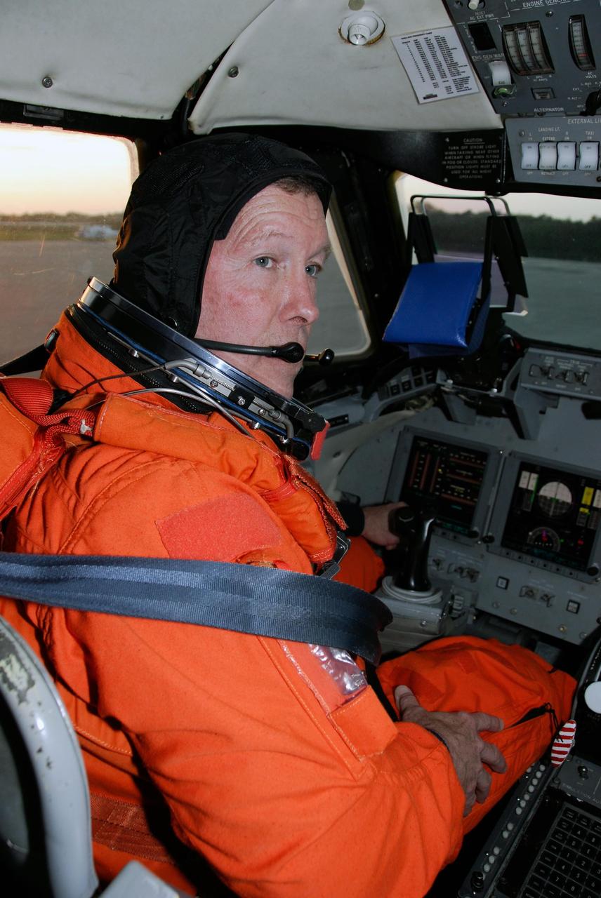
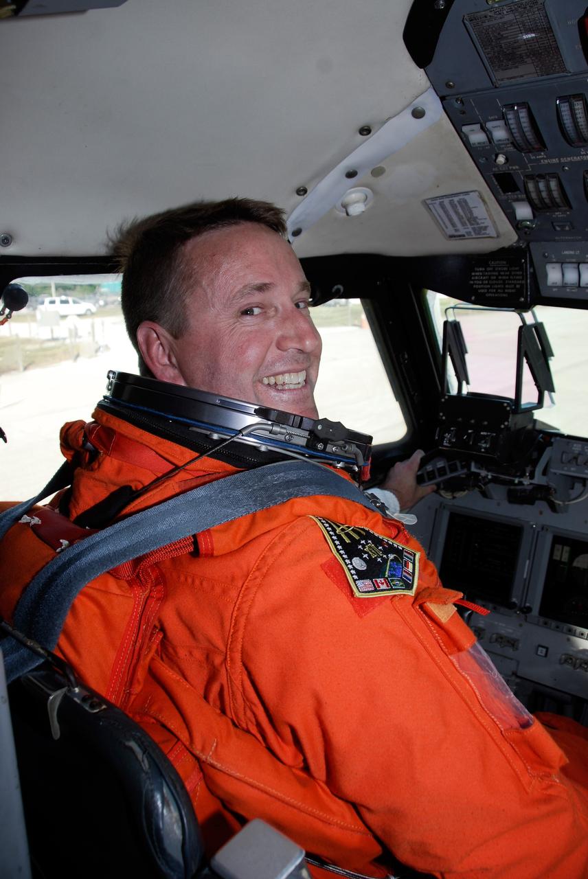
KENNEDY SPACE CENTER, FLA. -- At NASA Kennedy Space Center's Shuttle Landing Facility, STS-123 Commander Dominic Gorie prepares for takeoff in a Shuttle Training Aircraft, or STA, to practice space shuttle landings. The STA is a Grumman American Aviation-built Gulf Stream II jet that was modified to simulate an orbiter's cockpit, motion and visual cues, and handling qualities. In flight, the STA duplicates the orbiter's atmospheric descent trajectory from approximately 35,000 feet altitude to landing on a runway. Because the orbiter is unpowered during re-entry and landing, its high-speed glide must be perfectly executed the first time. The crew for space shuttle Endeavour's STS-123 mission is at Kennedy for a full launch dress rehearsal, known as the terminal countdown demonstration test or TCDT. The terminal countdown demonstration test provides astronauts and ground crews with an opportunity to participate in various simulated countdown activities, including equipment familiarization and emergency training. Endeavour is targeted to launch March 11 at 2:28 a.m. EDT on a 16-day mission to the International Space Station. On the mission, Endeavour and its crew will deliver the first section of the Japan Aerospace Exploration Agency's Kibo laboratory and the Canadian Space Agency's two-armed robotic system, Dextre. Photo credit: NASA/Kim Shiflett
CAPE CANAVERAL, Fla. -- NASA's Shuttle Training Aircraft, or STA, soars into the sky from the NASA Kennedy Space Center Shuttle Landing Facility with STS-124 Commander Mark Kelly or Pilot Ken Ham at the controls. Below is the Vehicle Assembly Building. Kelly and Ham are practicing space shuttle landings. The STA is a Grumman American Aviation-built Gulf Stream II jet that was modified to simulate an orbiter's cockpit, motion and visual cues, and handling qualities. In flight, the STA duplicates the orbiter's atmospheric descent trajectory from approximately 35,000 feet altitude to landing on a runway. Because the orbiter is unpowered during re-entry and landing, its high-speed glide must be perfectly executed the first time. The crew for space shuttle Discovery's STS-124 mission is at Kennedy for a full launch dress rehearsal, known as the terminal countdown demonstration test, or TCDT. Providing astronauts and ground crews with an opportunity to participate in various simulated countdown activities, TCDT includes equipment familiarization and emergency training. Discovery's launch is targeted for May 31. Photo credit: NASA/Kim Shiflett
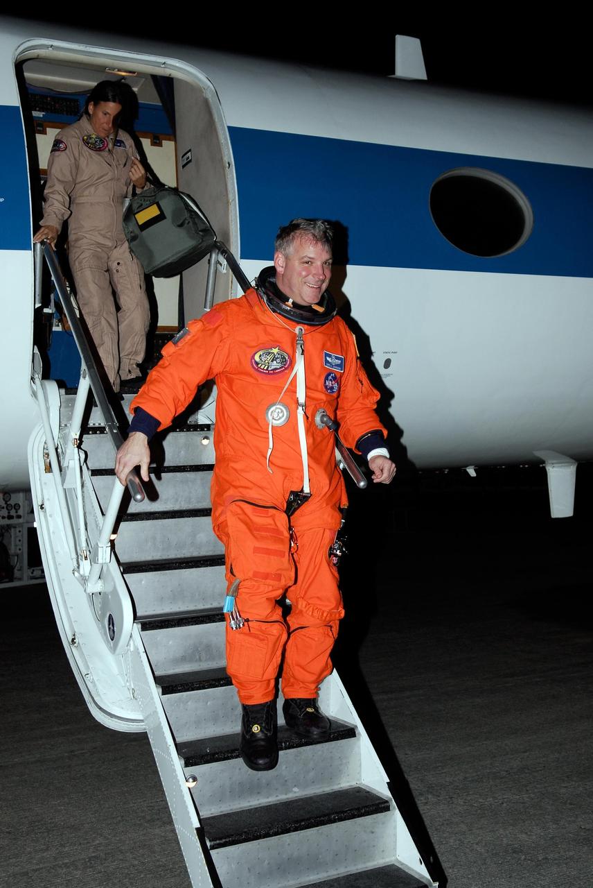
CAPE CANAVERAL, Fla. -- Back at the NASA Kennedy Space Center Shuttle Landing Facility, STS-124 Pilot Ken Ham is happy with the successful space shuttle landing practice aboard NASA's Shuttle Training Aircraft, or STA. Building. Kelly and Ham will be practicing space shuttle landings. The STA is a Grumman American Aviation-built Gulf Stream II jet that was modified to simulate an orbiter's cockpit, motion and visual cues, and handling qualities. In flight, the STA duplicates the orbiter's atmospheric descent trajectory from approximately 35,000 feet altitude to landing on a runway. Because the orbiter is unpowered during re-entry and landing, its high-speed glide must be perfectly executed the first time. The crew for space shuttle Discovery's STS-124 mission is at Kennedy for a full launch dress rehearsal, known as the terminal countdown demonstration test, or TCDT. Providing astronauts and ground crews with an opportunity to participate in various simulated countdown activities, TCDT includes equipment familiarization and emergency training. Discovery's launch is targeted for May 31. Photo credit: NASA/Kim Shiflett
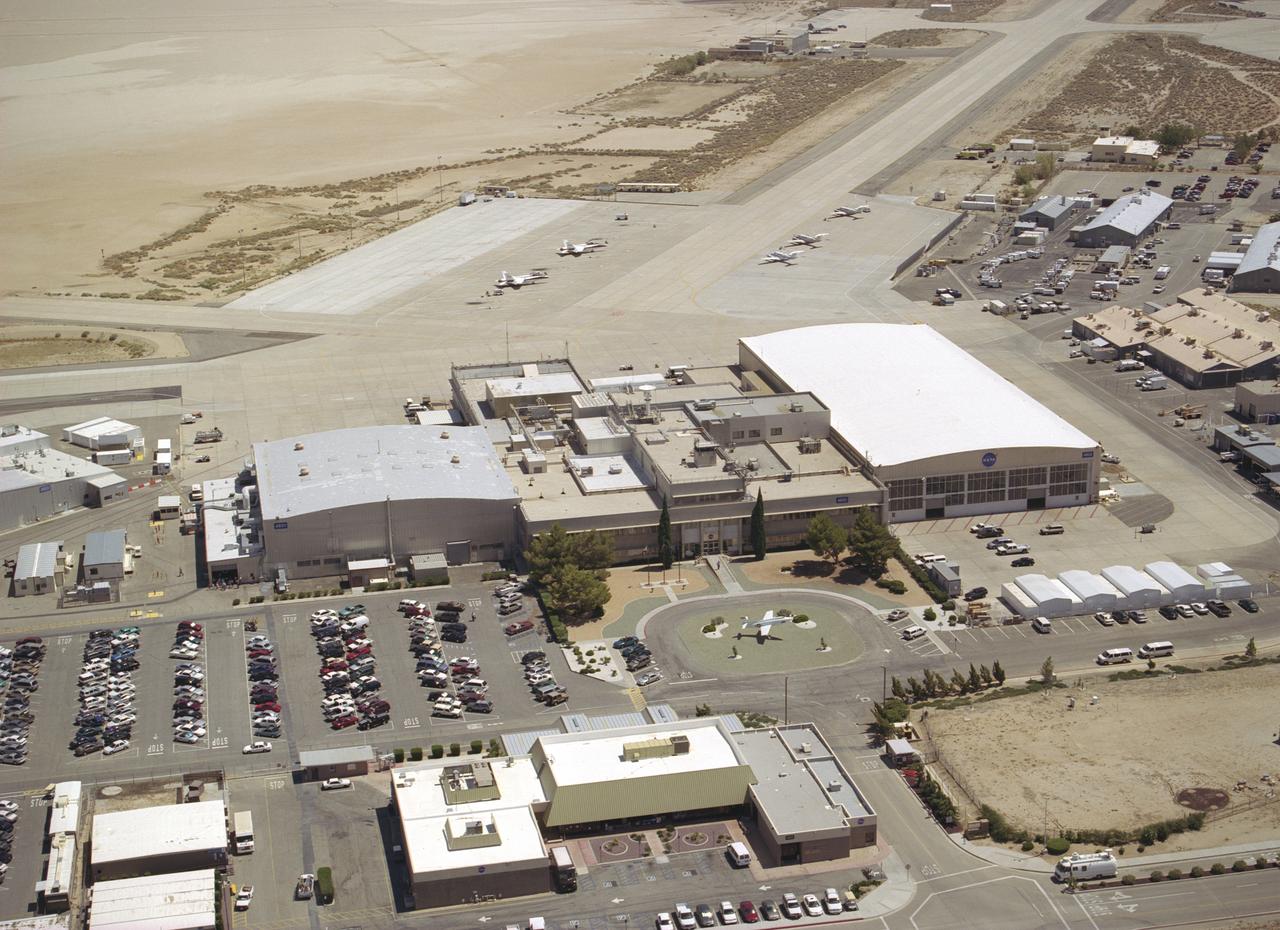
Since the 1940s the Dryden Flight Research Center, Edwards, California, has developed a unique and highly specialized capability for conducting flight research programs. The organization, made up of pilots, scientists, engineers, technicians, and mechanics, has been and will continue to be leaders in the field of advanced aeronautics. Located on the northwest "shore" of Rogers Dry Lake, the complex was built around the original administrative-hangar building constructed in 1954. Since then many additional support and operational facilities have been built including a number of unique test facilities such as the Thermalstructures Research Facility, Flow Visualization Facility, and the Integrated Test Facility. One of the most prominent structures is the space shuttle program's Mate-Demate Device and hangar in Area A to the north of the main complex. On the lakebed surface is a Compass Rose that gives pilots an instant compass heading. The Dryden complex originated at Edwards Air Force Base in support of the X-1 supersonic flight program. As other high-speed aircraft entered research programs, the facility became permanent and grew from a staff of five engineers in 1947 to a population in 2006 of nearly 1100 full-time government and contractor employees.
CAPE CANAVERAL, Fla. -- NASA's Shuttle Training Aircraft, or STA, taxis to the runway at the NASA Kennedy Space Center Shuttle Landing Facility. STS-124 Commander Mark Kelly and Pilot Ken Ham are practicing space shuttle landings. The STA is a Grumman American Aviation-built Gulf Stream II jet that was modified to simulate an orbiter's cockpit, motion and visual cues, and handling qualities. In flight, the STA duplicates the orbiter's atmospheric descent trajectory from approximately 35,000 feet altitude to landing on a runway. Because the orbiter is unpowered during re-entry and landing, its high-speed glide must be perfectly executed the first time. The crew for space shuttle Discovery's STS-124 mission is at Kennedy for a full launch dress rehearsal, known as the terminal countdown demonstration test, or TCDT. Providing astronauts and ground crews with an opportunity to participate in various simulated countdown activities, TCDT includes equipment familiarization and emergency training. Discovery's launch is targeted for May 31. Photo credit: NASA/Kim Shiflett
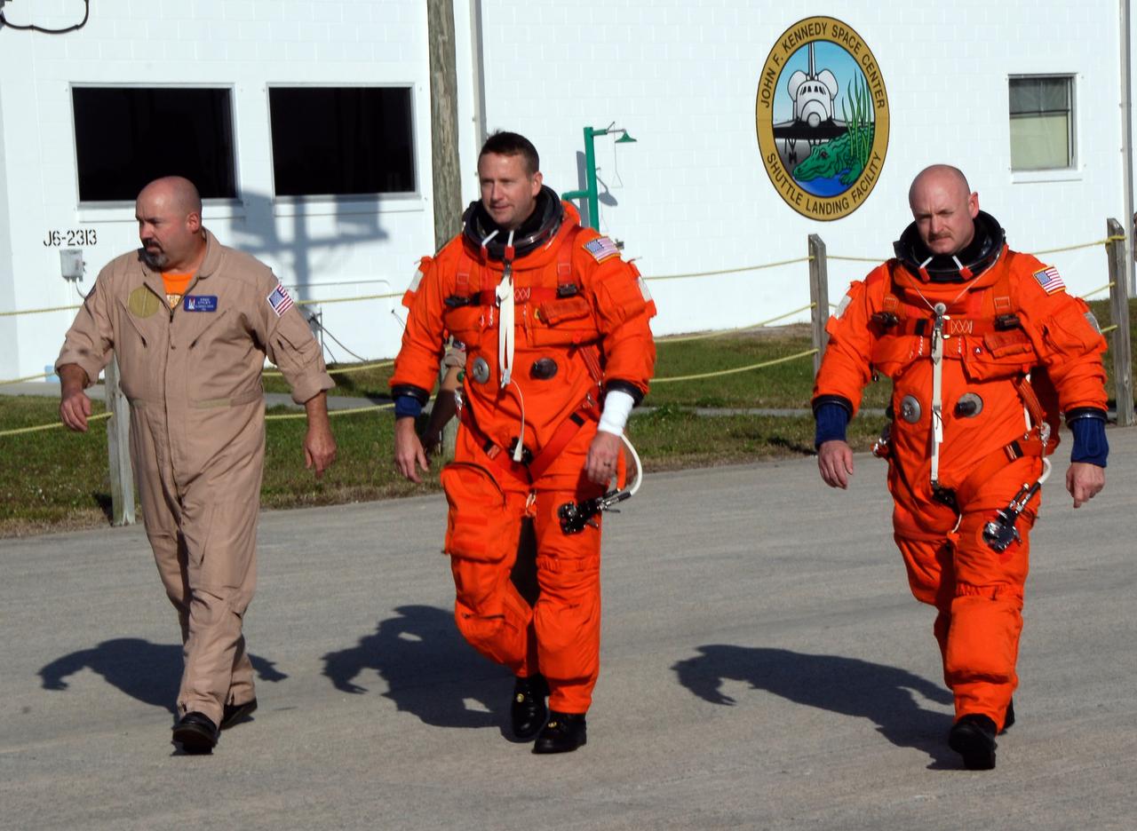
CAPE CANAVERAL, Fla. -- After their arrival at the NASA Kennedy Space Center Shuttle Landing Facility, STS-124 Pilot Ken Ham (center) and Commander Mark Kelly (right) head for the runway to practice space shuttle landings using NASA's Shuttle Training Aircraft, or STA. The STA is a Grumman American Aviation-built Gulf Stream II jet that was modified to simulate an orbiter's cockpit, motion and visual cues, and handling qualities. In flight, the STA duplicates the orbiter's atmospheric descent trajectory from approximately 35,000 feet altitude to landing on a runway. Because the orbiter is unpowered during re-entry and landing, its high-speed glide must be perfectly executed the first time. The crew for space shuttle Discovery's STS-124 mission is at Kennedy for a full launch dress rehearsal, known as the terminal countdown demonstration test, or TCDT. Providing astronauts and ground crews with an opportunity to participate in various simulated countdown activities, TCDT includes equipment familiarization and emergency training. Discovery's launch is targeted for May 31. Photo credit: NASA/Kim Shiflett
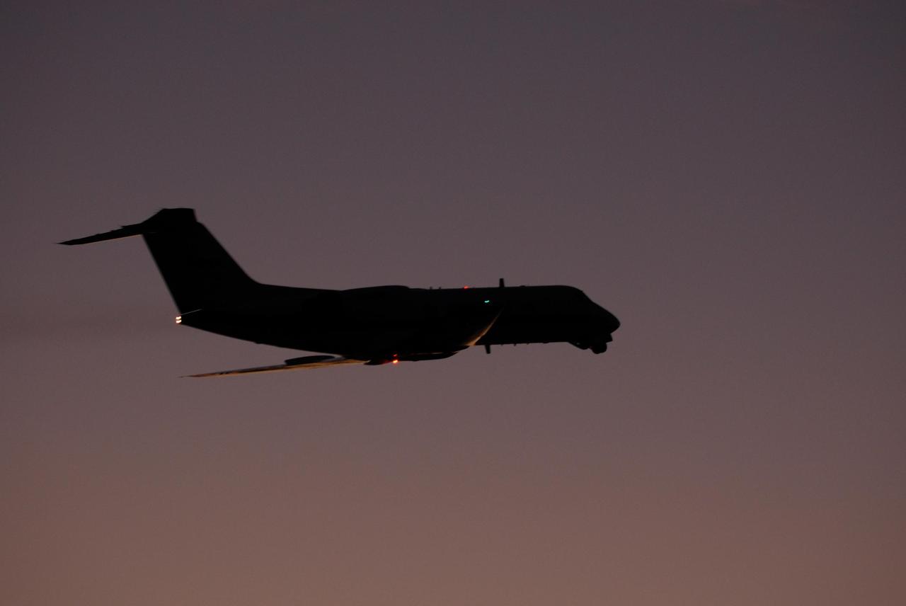
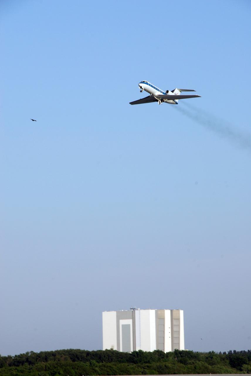
KENNEDY SPACE CENTER, FLA. -- At NASA Kennedy Space Center's Shuttle Landing Facility, a Shuttle Training Aircraft, or STA, takes flight for practice space shuttle landings. The STA is a Grumman American Aviation-built Gulf Stream II jet that was modified to simulate an orbiter's cockpit, motion and visual cues, and handling qualities. In flight, the STA duplicates the orbiter's atmospheric descent trajectory from approximately 35,000 feet altitude to landing on a runway. Because the orbiter is unpowered during re-entry and landing, its high-speed glide must be perfectly executed the first time. The crew for space shuttle Endeavour's STS-123 mission is at Kennedy for a full launch dress rehearsal, known as the terminal countdown demonstration test or TCDT. The terminal countdown demonstration test provides astronauts and ground crews with an opportunity to participate in various simulated countdown activities, including equipment familiarization and emergency training. Endeavour is targeted to launch March 11 at 2:28 a.m. EDT on a 16-day mission to the International Space Station. On the mission, Endeavour and its crew will deliver the first section of the Japan Aerospace Exploration Agency's Kibo laboratory and the Canadian Space Agency's two-armed robotic system, Dextre. Photo credit: NASA/Kim Shiflett
KENNEDY SPACE CENTER, FLA. - STS-115 Commander Brent Jett settles in the cockpit of the Shuttle Training Aircraft to practice landing the shuttle. STA practice is part of launch preparations. The STA is a Grumman American Aviation-built Gulf Stream II jet that was modified to simulate an orbiter’s cockpit, motion and visual cues, and handling qualities. In flight, the STA duplicates the orbiter’s atmospheric descent trajectory from approximately 35,000 feet altitude to landing on a runway. Because the orbiter is unpowered during re-entry and landing, its high-speed glide must be perfectly executed the first time. Mission STS-115 is scheduled to lift off about 12:29 p.m. Sept. 6. Mission managers cancelled Atlantis' first launch campaign due to a lightning strike at the pad and the passage of Tropical Storm Ernesto along Florida's east coast. The mission will deliver and install the 17-and-a-half-ton P3/P4 truss segment to the port side of the integrated truss system on the orbital outpost. The truss includes a new set of photovoltaic solar arrays. When unfurled to their full length of 240 feet, the arrays will provide additional power for the station in preparation for the delivery of international science modules over the next two years. STS-115 is expected to last 11 days and includes three scheduled spacewalks. Photo credit: NASA/Kim Shiflett
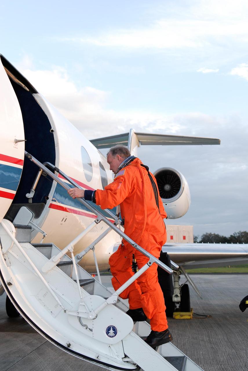
KENNEDY SPACE CENTER, FLA. -- At NASA Kennedy Space Center's Shuttle Landing Facility, STS-123 Commander Dominic Gorie boards a Shuttle Training Aircraft, or STA, to practice space shuttle landings. The STA is a Grumman American Aviation-built Gulf Stream II jet that was modified to simulate an orbiter's cockpit, motion and visual cues, and handling qualities. In flight, the STA duplicates the orbiter's atmospheric descent trajectory from approximately 35,000 feet altitude to landing on a runway. Because the orbiter is unpowered during re-entry and landing, its high-speed glide must be perfectly executed the first time. The crew for space shuttle Endeavour's STS-123 mission is at Kennedy for a full launch dress rehearsal, known as the terminal countdown demonstration test or TCDT. The terminal countdown demonstration test provides astronauts and ground crews with an opportunity to participate in various simulated countdown activities, including equipment familiarization and emergency training. Endeavour is targeted to launch March 11 at 2:28 a.m. EDT on a 16-day mission to the International Space Station. On the mission, Endeavour and its crew will deliver the first section of the Japan Aerospace Exploration Agency's Kibo laboratory and the Canadian Space Agency's two-armed robotic system, Dextre. Photo credit: NASA/Kim Shiflett
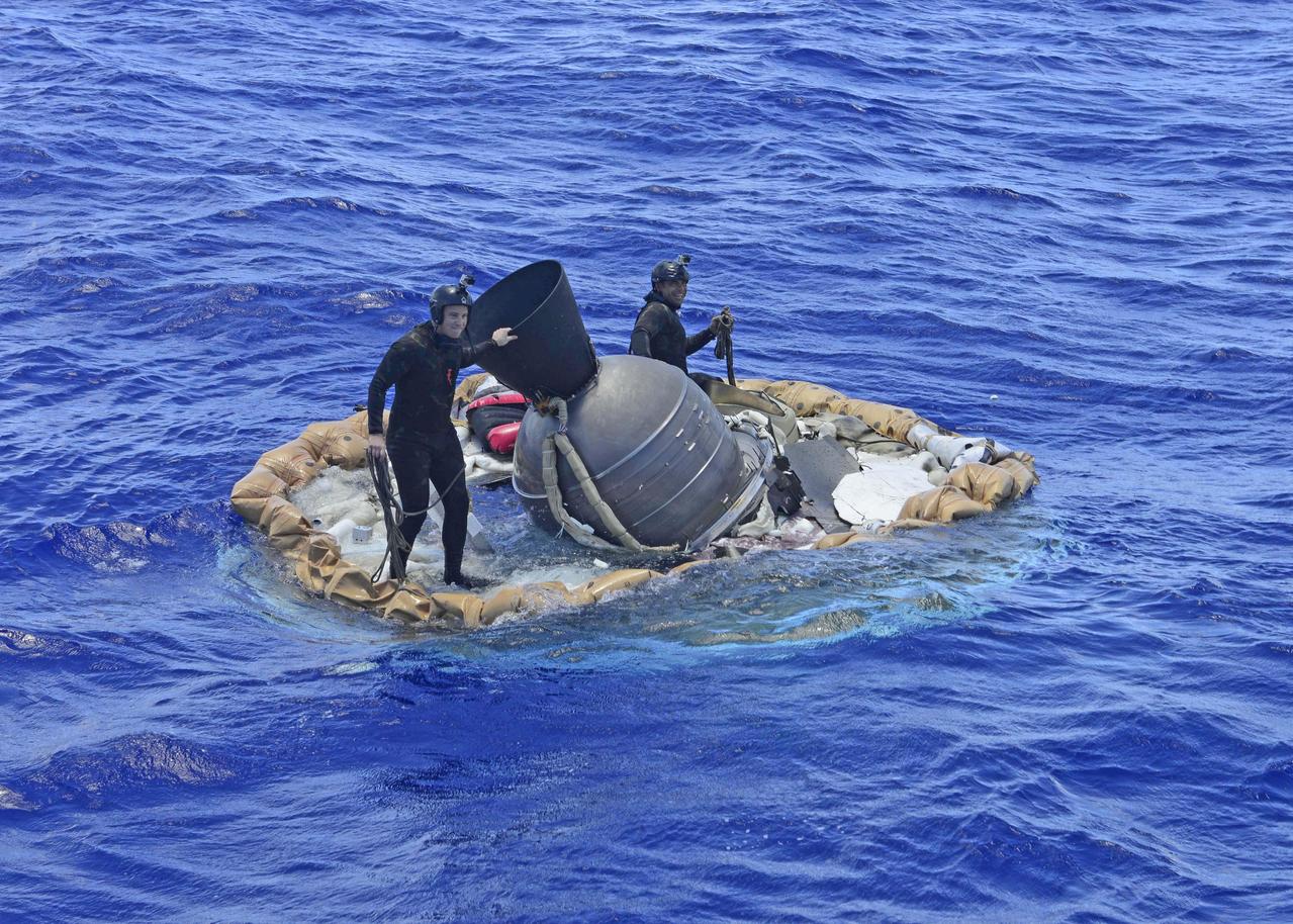
Two members of the U.S. Navy's Mobile Diving Salvage Unit (MDSU) 1 Explosive Ordnance Detachment work on recovering the test vehicle for NASA's Low-Density Supersonic Decelerator (LDSD) project. The saucer-shaped LDSD craft splashed down at 11:49 a.m. HST (2:49 PDT/5:49 p.m. EDT) Monday, June 8, 2015, in the Pacific Ocean off the west coast of the Kauai, Hawaii, after a four-hour experimental flight test that investigated new technologies for landing future robotic and human Mars missions. During the flight test, a Supersonic Inflatable Aerodynamic Decelerator (SIAD) and a supersonic parachute were deployed. The SIAD operated as expected, dramatically slowing the test vehicle's velocity. When the parachute was deployed into the supersonic slipstream, it appeared to blossom to full inflation prior to the emergence of a tear which then propagated and destroyed the parachute's canopy. As a result, the saucer's splashdown in the Pacific Ocean was hard, resulting in fracturing parts of the structure. Memory cards containing comprehensive test data -- including high-speed, high-resolution imagery recorded during the flight -- were successfully recovered. Also recovered were the test vehicle and its components, the supersonic parachute, the ballute used to deploy the parachute, and a large weather balloon that initially carried the saucer to an altitude of 120,000 feet. http://photojournal.jpl.nasa.gov/catalog/PIA19684

KENNEDY SPACE CENTER, FLA. - STS-115 Commander Brent Jett studies the controls in the cockpit of the Shuttle Training Aircraft before a practice session of landing the shuttle. STA practice is part of launch preparations. The STA is a Grumman American Aviation-built Gulf Stream II jet that was modified to simulate an orbiter’s cockpit, motion and visual cues, and handling qualities. In flight, the STA duplicates the orbiter’s atmospheric descent trajectory from approximately 35,000 feet altitude to landing on a runway. Because the orbiter is unpowered during re-entry and landing, its high-speed glide must be perfectly executed the first time. Mission STS-115 is scheduled to lift off about 12:29 p.m. Sept. 6. Mission managers cancelled Atlantis' first launch campaign due to a lightning strike at the pad and the passage of Tropical Storm Ernesto along Florida's east coast. The mission will deliver and install the 17-and-a-half-ton P3/P4 truss segment to the port side of the integrated truss system on the orbital outpost. The truss includes a new set of photovoltaic solar arrays. When unfurled to their full length of 240 feet, the arrays will provide additional power for the station in preparation for the delivery of international science modules over the next two years. STS-115 is expected to last 11 days and includes three scheduled spacewalks. Photo credit: NASA/Kim Shiflett

One of the two primary coolers at the Propulsion Systems Laboratory at the National Advisory Committee for Aeronautics (NACA) Lewis Flight Propulsion Laboratory. Engines could be run in simulated altitude conditions inside the facility’s two 14-foot-diameter and 24-foot-long test chambers. The Propulsion Systems Laboratory was the nation’s only facility that could run large full-size engine systems in controlled altitude conditions. At the time of this photograph, construction of the facility had recently been completed. Although not a wind tunnel, the Propulsion Systems Laboratory generated high-speed airflow through the interior of the engine. The air flow was pushed through the system by large compressors, adjusted by heating or refrigerating equipment, and de-moisturized by air dryers. The exhaust system served two roles: reducing the density of the air in the test chambers to simulate high altitudes and removing hot gases exhausted by the engines being tested. It was necessary to reduce the temperature of the extremely hot engine exhaust before the air reached the exhauster equipment. As the air flow exited through exhaust section of the test chamber, it entered into the giant primary cooler seen in this photograph. Narrow fins or vanes inside the cooler were filled with water. As the air flow passed between the vanes, its heat was transferred to the cooling water. The cooling water was cycled out of the system, carrying with it much of the exhaust heat.
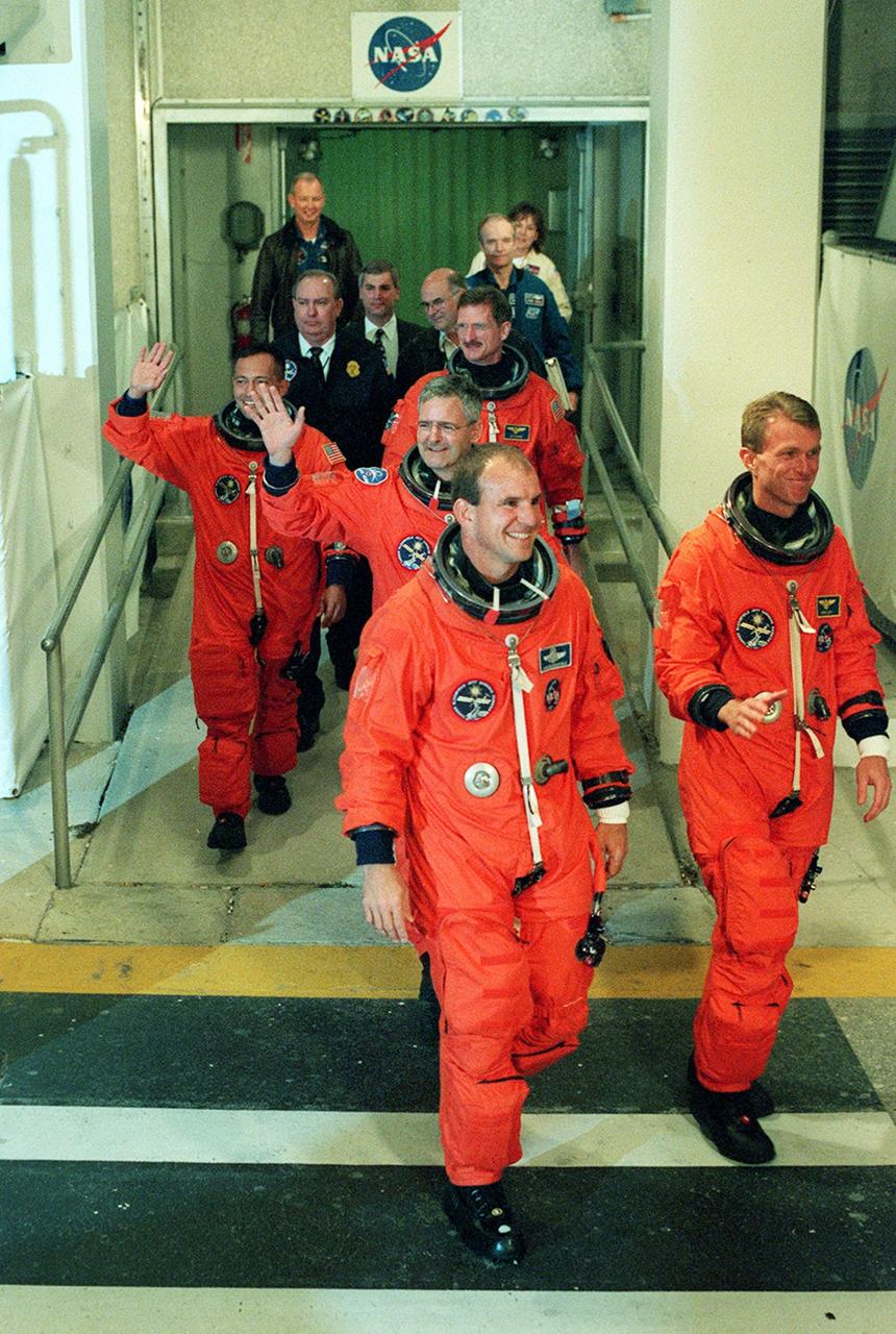
Eager to speed into space, the STS-97 crew hurries out of the Operations and Checkout Building for the ride to Launch Pad 39B. Leading the way are Pilot Michael Bloomfield (left) and Commander Brent Jett (right). In the middle is Mission Specialist Marc Garneau (waving), who is with the Canadian Space Agency. Behind are Mission Specialists Carlos Noriega (left, waving) and Joseph Tanner. Mission STS-97 is the sixth construction flight to the International Space Station. It is transporting the P6 Integrated Truss Structure that comprises Solar Array Wing-3 and the Integrated Electronic Assembly, to be installed on the Space Station. The solar arrays are mounted on a “blanket” that can be folded like an accordion for delivery. Once in orbit, astronauts will deploy the blankets to their full size. The 11-day mission includes two spacewalks to complete the solar array connections. The Station’s electrical power system will use eight photovoltaic solar arrays, each 112 feet long by 39 feet wide, to convert sunlight to electricity. Gimbals will be used to rotate the arrays so that they will face the Sun to provide maximum power to the Space Station. Launch is scheduled for Nov. 30 at 10:06 p.m. EST
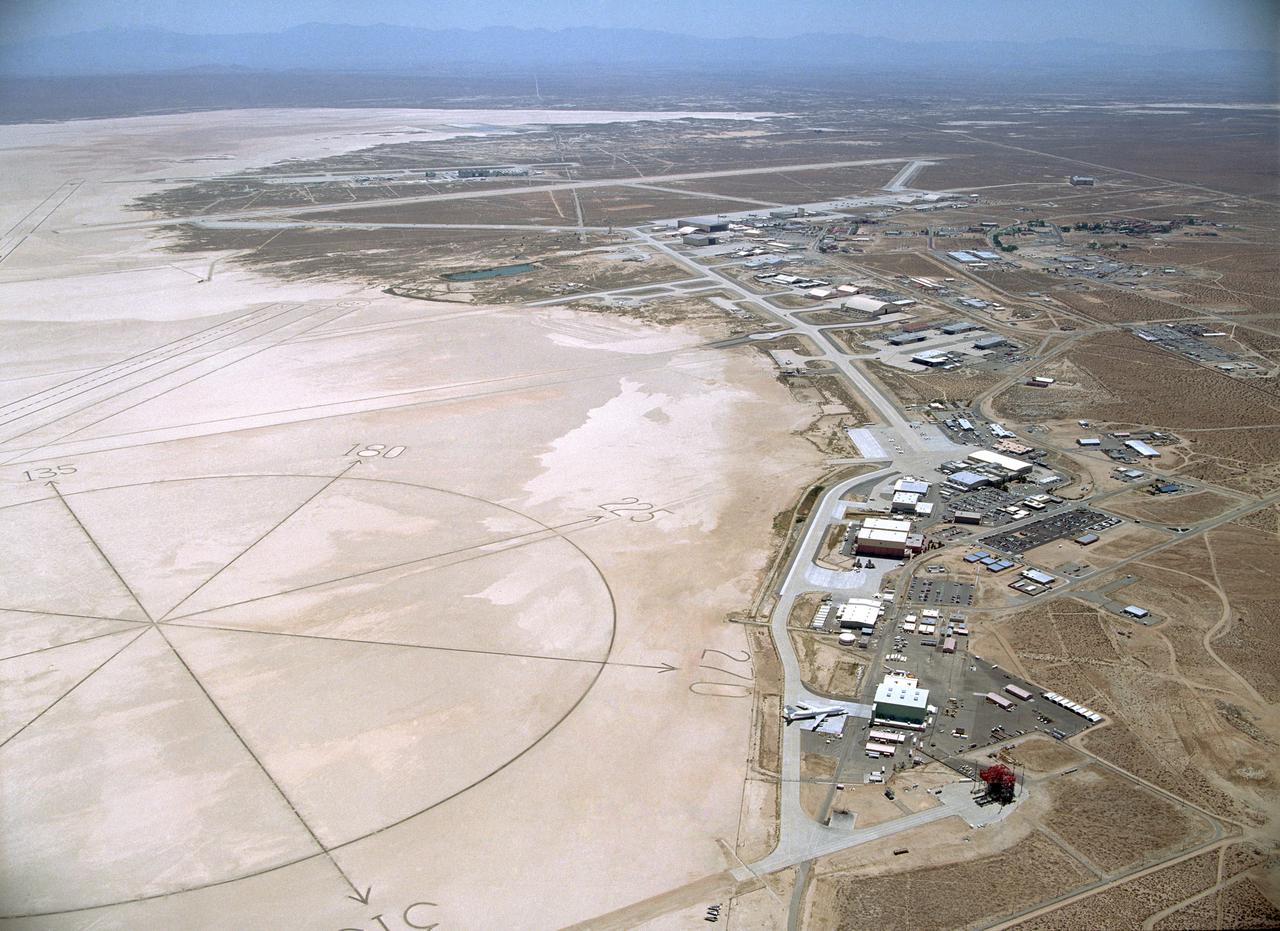
Since the 1940s the Dryden Flight Research Center, Edwards, California, has developed a unique and highly specialized capability for conducting flight research programs. The organization, made up of pilots, scientists, engineers, technicians, and mechanics, has been and will continue to be leaders in the field of advanced aeronautics. Located on the northwest "shore" of Rogers Dry Lake, the complex was built around the original administrative-hangar building constructed in 1954. Since then many additional support and operational facilities have been built including a number of unique test facilities such as the Thermalstructures Research Facility, Flow Visualization Facility, and the Integrated Test Facility. One of the most prominent structures is the space shuttle program's Mate-Demate Device and hangar in Area A to the north of the main complex. On the lakebed surface is a Compass Rose that gives pilots an instant compass heading. The Dryden complex originated at Edwards Air Force Base in support of the X-1 supersonic flight program. As other high-speed aircraft entered research programs, the facility became permanent and grew from a staff of five engineers in 1947 to a population in 2006 of nearly 1100 full-time government and contractor employees.
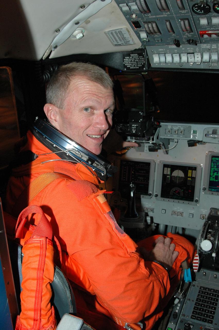
KENNEDY SPACE CENTER, FLA. - STS-115 Commander Brent Jett settles in the cockpit of the Shuttle Training Aircraft to practice landing the shuttle. STA practice is part of launch preparations. The STA is a Grumman American Aviation-built Gulf Stream II jet that was modified to simulate an orbiter’s cockpit, motion and visual cues, and handling qualities. In flight, the STA duplicates the orbiter’s atmospheric descent trajectory from approximately 35,000 feet altitude to landing on a runway. Because the orbiter is unpowered during re-entry and landing, its high-speed glide must be perfectly executed the first time. Mission STS-115 is scheduled to lift off about 4:30 p.m. Aug. 27. The crew will deliver and install the P3/P4 segment to the port side of the integrated truss system on the International Space Station. The truss includes a new set of photovoltaic solar arrays. When unfurled to their full length of 240 feet, the arrays will provide additional power for the station in preparation for the delivery of international science modules over the next two years. The mission is expected to last 11 days and includes three scheduled spacewalks. Photo credit: NASA/Kim Shiflett
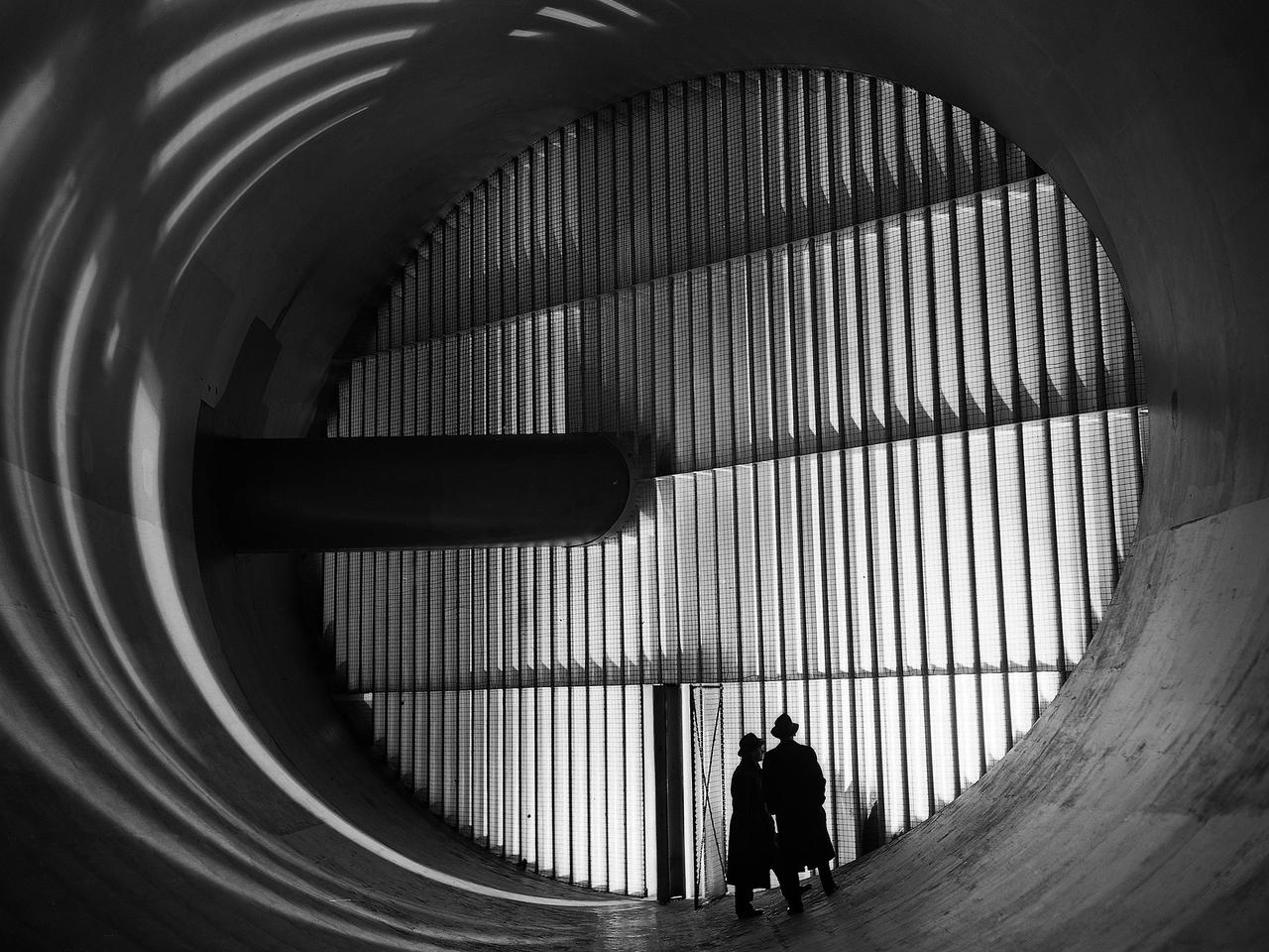
Men stand in front of turning vanes inside the Altitude Wind Tunnel (AWT) at the National Advisory Committee for Aeronautics (NACA) Aircraft Engine Research Laboratory. The AWT was the only wind tunnel capable of testing full-size aircraft engines in simulated altitude conditions. A large wooden drive fan, located on the other side of these vanes, created wind speeds up to 500 miles per hour. The drive shaft connected the fan to the induction motor located in an adjacent building. Turning vanes were located in each corner of the rectangular tunnel to straighten the airflow and direct it around the corners. This set of vanes was located in the 31-foot-diameter southeast corner of the tunnel. These elliptical panels consisted of 36 to 42 vertical vanes that were supported by three horizontal supports. The individual vanes were 2.5 feet long and half-moon shaped. The panel of vanes was affixed to the curved corner rings of the tunnel. Each set of turning vanes had a moveable vane in the middle of the lower level for personnel access. Each set of vanes took weeks to assemble before they were installed during the summer of 1943. This publicity photograph was taken just weeks after the tunnel became operational in February 1944.
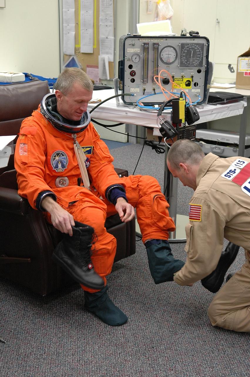
KENNEDY SPACE CENTER, FLA. - STS-115 Commander Brent Jett is helped donning his launch suit before flying the Shuttle Training Aircraft to practice landing the shuttle. STA practice is part of launch preparations. The STA is a Grumman American Aviation-built Gulf Stream II jet that was modified to simulate an orbiter’s cockpit, motion and visual cues, and handling qualities. In flight, the STA duplicates the orbiter’s atmospheric descent trajectory from approximately 35,000 feet altitude to landing on a runway. Because the orbiter is unpowered during re-entry and landing, its high-speed glide must be perfectly executed the first time. Mission STS-115 is scheduled to lift off about 4:30 p.m. Aug. 27. The crew will deliver and install the P3/P4 segment to the port side of the integrated truss system on the International Space Station. The truss includes a new set of photovoltaic solar arrays. When unfurled to their full length of 240 feet, the arrays will provide additional power for the station in preparation for the delivery of international science modules over the next two years. The mission is expected to last 11 days and includes three scheduled spacewalks. Photo credit: NASA/Kim Shiflett
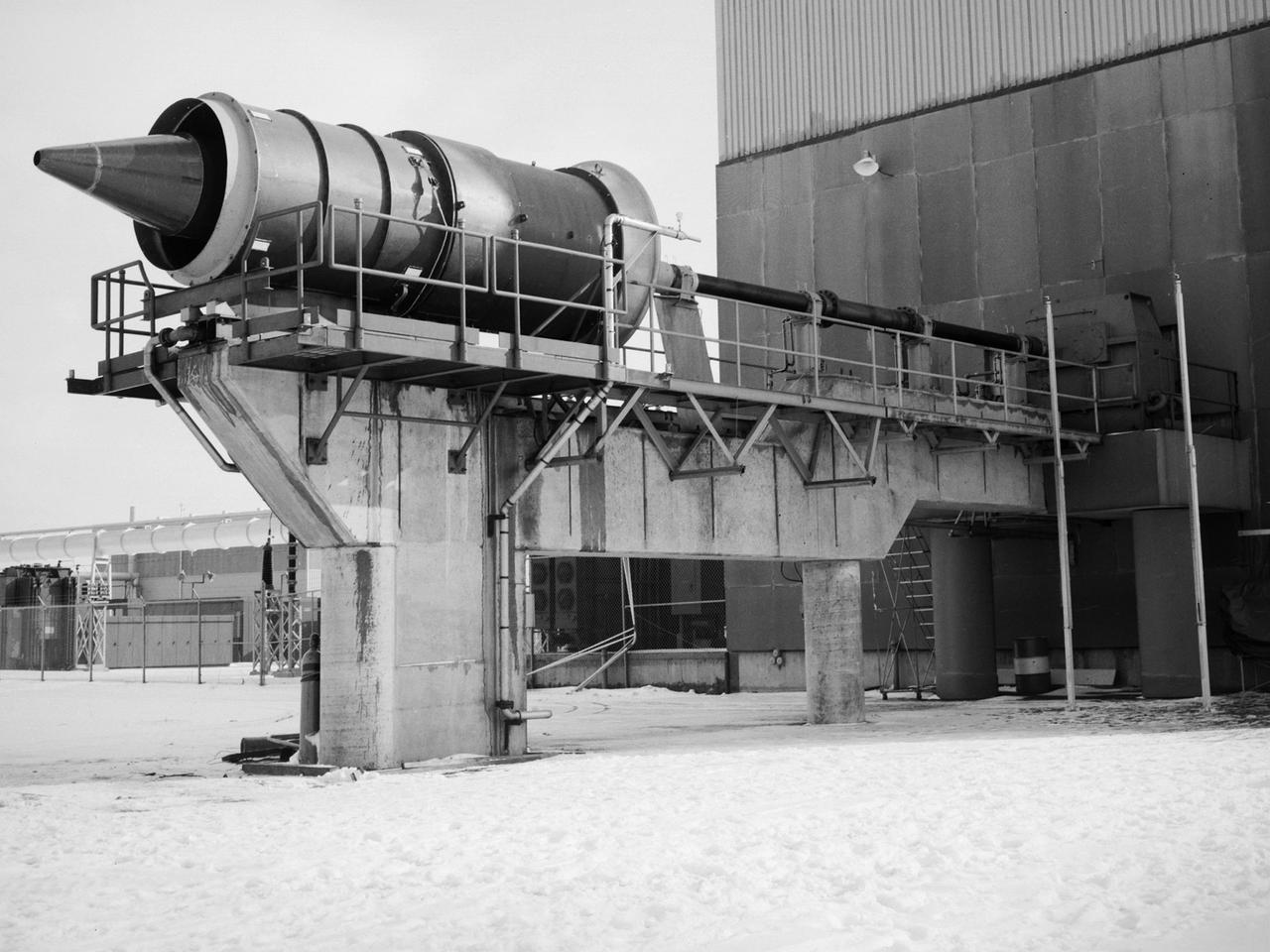
The Fan Noise Test Facility built at the Lewis Research Center to obtain far-field noise data for the National Aeronautics and Space Administration (NASA) and General Electric Quiet Engine Program. The engine incorporated existing noise reduction methods into an engine of similar power to those that propelled the Boeing 707 or McDonnell-Douglas DC-8 airliner. The new the low-bypass ratio turbofan engines of the 1960s were inherently quieter than their turbojet counterparts, researchers had a better grasp of the noise generation problem, and new acoustic technologies had emerged. Lewis contracted General Electric in 1969 to build and aerodynamically test three experimental engines with 72-inch diameter fans. The engines were then brought to Lewis and tested with an acoustically treated nacelle. This Fan Noise Test Facility was built off of the 10- by 10-Foot Supersonic Wind Tunnel’s Main Compressor and Drive Building. Lewis researchers were able to isolate the fan’s noise during these initial tests by removing the core of the engine. The Lewis test rig drove engines to takeoff tip speeds of 1160 feet per second. The facility was later used to test a series of full-scale model fans and fan noise suppressors to be used with the quiet engine. NASA researchers predicted low-speed single-stage fans without inlet guide vanes and with large spacing between rotors and stators would be quieter. General Electric modified a TF39 turbofan engine by removing the the outer protion of the fan and spacing the blade rows of the inner portion. The tests revealed that the untreated version of the engine generated less noise than was anticipated, and the acoustically treated nacelle substantially reduced engine noise.
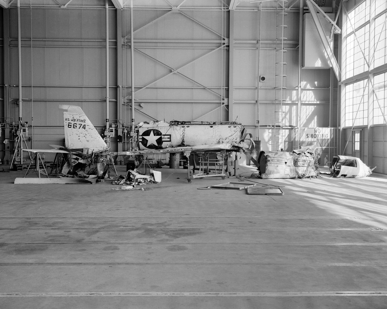
The X-2, initially an Air Force program, was scheduled to be transferred to the civilian National Advisory Committee for Aeronautics (NACA) for scientific research. The Air Force delayed turning the aircraft over to the NACA in the hope of attaining Mach 3 in the airplane. The service requested and received a two-month extension to qualify another Air Force test pilot, Capt. Miburn "Mel" Apt, in the X-2 and attempt to exceed Mach 3. After several ground briefings in the simulator, Apt (with no previous rocket plane experience) made his flight on 27 September 1956. Apt raced away from the B-50 under full power, quickly outdistancing the F-100 chase planes. At high altitude, he nosed over, accelerating rapidly. The X-2 reached Mach 3.2 (2,094 mph) at 65,000 feet. Apt became the first man to fly more than three times the speed of sound. Still above Mach 3, he began an abrupt turn back to Edwards. This maneuver proved fatal as the X-2 began a series of diverging rolls and tumbled out of control. Apt tried to regain control of the aircraft. Unable to do so, Apt separated the escape capsule. Too late, he attempted to bail out and was killed when the capsule impacted on the Edwards bombing range. The rest of the X-2 crashed five miles away. The wreckage of the X-2 rocket plane was later taken to NACA's High Speed Flight Station for analysis following the crash.
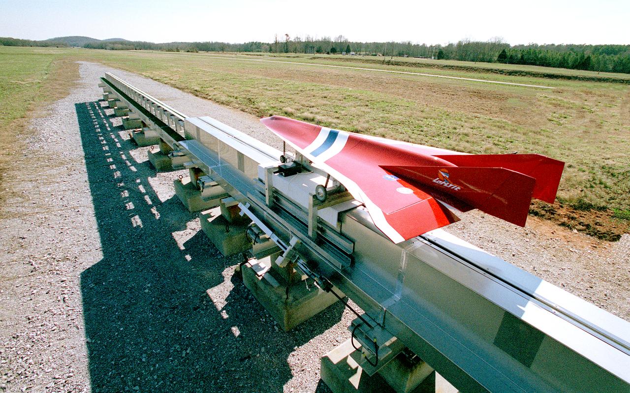
Engineers at the Marshall Space Flight Center (MSFC) have been testing Magnetic Launch Assist Systems, formerly known as Magnetic Levitation (MagLev) technologies. To launch spacecraft into orbit, a Magnetic Launch Assist system would use magnetic fields to levitate and accelerate a vehicle along a track at a very high speed. Similar to high-speed trains and roller coasters that use high-strength magnets to lift and propel a vehicle a couple of inches above a guideway, the launch-assist system would electromagnetically drive a space vehicle along the track. A full-scale, operational track would be about 1.5-miles long and capable of accelerating a vehicle to 600 mph in 9.5 seconds. This photograph shows a subscale model of an airplane running on the experimental track at MSFC during the demonstration test. This track is an advanced linear induction motor. Induction motors are common in fans, power drills, and sewing machines. Instead of spinning in a circular motion to turn a shaft or gears, a linear induction motor produces thrust in a straight line. Mounted on concrete pedestals, the track is 100-feet long, about 2-feet wide, and about 1.5- feet high. The major advantages of launch assist for NASA launch vehicles is that it reduces the weight of the take-off, the landing gear, the wing size, and less propellant resulting in significant cost savings. The US Navy and the British MOD (Ministry of Defense) are planning to use magnetic launch assist for their next generation aircraft carriers as the aircraft launch system. The US Army is considering using this technology for launching target drones for anti-aircraft training.
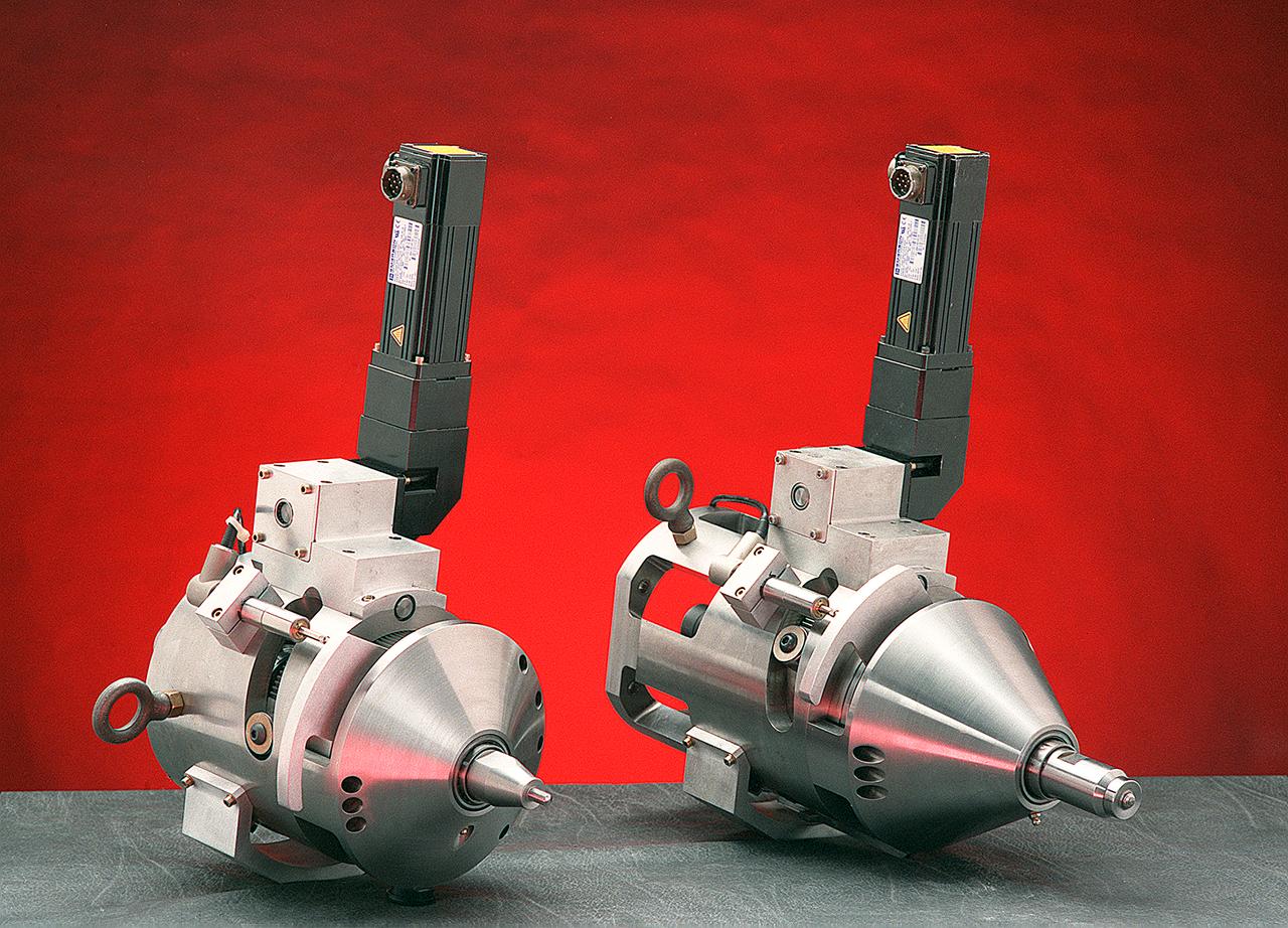
Two companies have successfully commercialized a specialized welding tool developed at the Marshall Space Flight Center (MSFC). Friction stir welding uses the high rotational speed of a tool and the resulting frictional heat created from contact to crush, "stir" together, and forge a bond between two metal alloys. It has had a major drawback, reliance on a single-piece pin tool. The pin is slowly plunged into the joint between two materials to be welded and rotated as high speed. At the end of the weld, the single-piece pin tool is retracted and leaves a "keyhole," something which is unacceptable when welding cylindrical objects such as drums, pipes and storage tanks. Another drawback is the requirement for different-length pin tools when welding materials of varying thickness. An engineer at the MSFC helped design an automatic retractable pin tool that uses a computer-controlled motor to automatically retract the pin into the shoulder of the tool at the end of the weld, preventing keyholes. This design allows the pin angle and length to be adjusted for changes in material thickness and results in a smooth hole closure at the end of the weld. Benefits of friction stir welding, using the MSFC retractable pin tool technology, include the following: The ability to weld a wide range of alloys, including previously unweldable and composite materials; provision of twice the fatigue resistance of fusion welds and no keyholes; minimization of material distortion; no creation of hazards such as welding fumes, radiation, high voltage, liquid metals, or arcing; automatic retraction of the pin at the end of the weld; and maintaining full penetration of the pin.
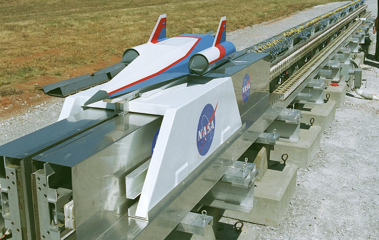
In this photograph, a futuristic spacecraft model sits atop a carrier on the Magnetic Launch Assist System, formerly known as the Magnetic Levitation (MagLev) System, experimental track at the Marshall Space Flight Center (MSFC). Engineers at MSFC have developed and tested Magnetic Launch Assist technologies that would use magnetic fields to levitate and accelerate a vehicle along a track at very high speeds. Similar to high-speed trains and roller coasters that use high-strength magnets to lift and propel a vehicle a couple of inches above a guideway, a Magnetic Launch Assist system would electromagnetically drive a space vehicle along the track. A full-scale, operational track would be about 1.5-miles long and capable of accelerating a vehicle to 600 mph in 9.5 seconds. This track is an advanced linear induction motor. Induction motors are common in fans, power drills, and sewing machines. Instead of spinning in a circular motion to turn a shaft or gears, a linear induction motor produces thrust in a straight line. Mounted on concrete pedestals, the track is 100-feet long, about 2-feet wide, and about 1.5-feet high. The major advantages of launch assist for NASA launch vehicles is that it reduces the weight of the take-off, the landing gear, the wing size, and less propellant resulting in significant cost savings. The US Navy and the British MOD (Ministry of Defense) are planning to use magnetic launch assist for their next generation aircraft carriers as the aircraft launch system. The US Army is considering using this technology for launching target drones for anti-aircraft training.
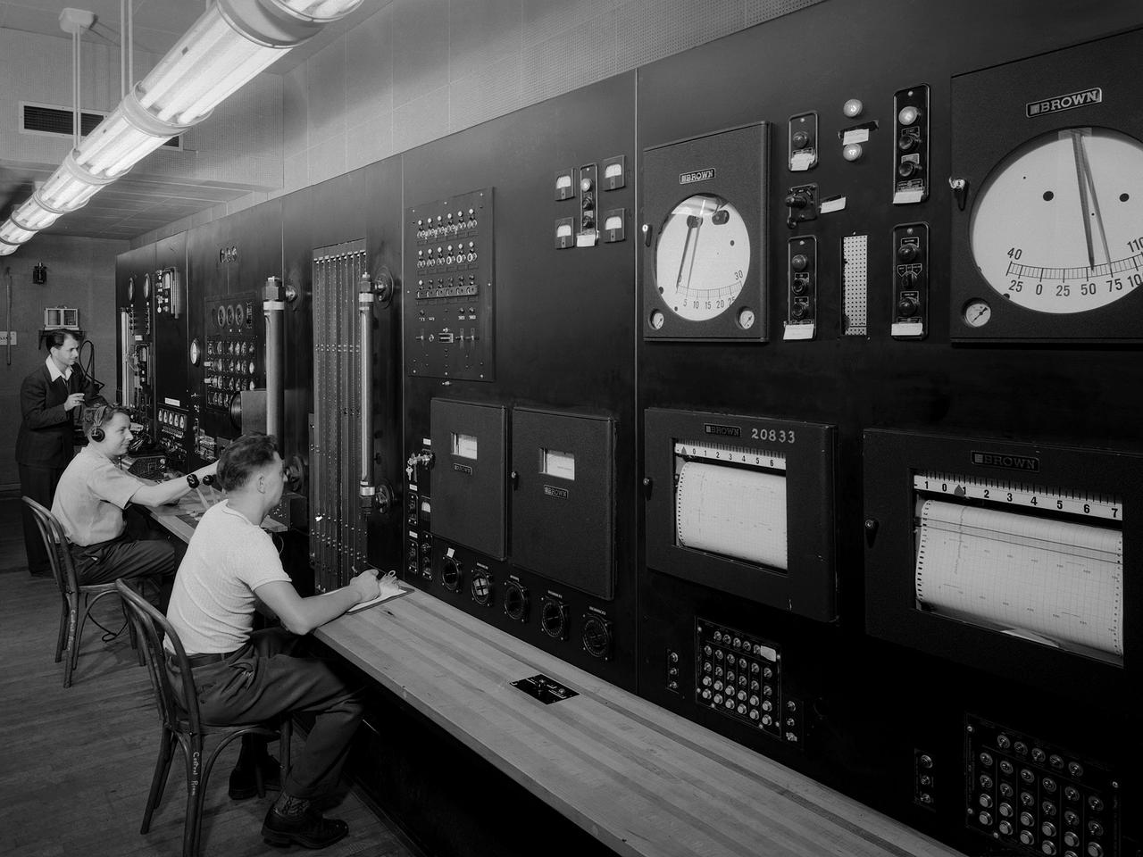
Operators in the control room for the Altitude Wind Tunnel at the National Advisory Committee for Aeronautics (NACA) Aircraft Engine Research Laboratory remotely operate a Wright R–3350 engine in the tunnel’s test section. Four of the engines were used to power the B–29 Superfortress, a critical weapon in the Pacific theater during World War II. The wind tunnel, which had been in operation for approximately six months, was the nation’s only wind tunnel capable of testing full-scale engines in simulated altitude conditions. The soundproof control room was used to operate the wind tunnel and control the engine being run in the test section. The operators worked with assistants in the adjacent Exhauster Building and Refrigeration Building to manage the large altitude simulation systems. The operator at the center console controlled the tunnel’s drive fan and operated the engine in the test section. Two sets of pneumatic levers near his right forearm controlled engine fuel flow, speed, and cooling. Panels on the opposite wall, out of view to the left, were used to manage the combustion air, refrigeration, and exhauster systems. The control panel also displayed the master air speed, altitude, and temperature gauges, as well as a plethora of pressure, temperature, and airflow readings from different locations on the engine. The operator to the right monitored the manometer tubes to determine the pressure levels. Despite just being a few feet away from the roaring engine, the control room remained quiet during the tests.
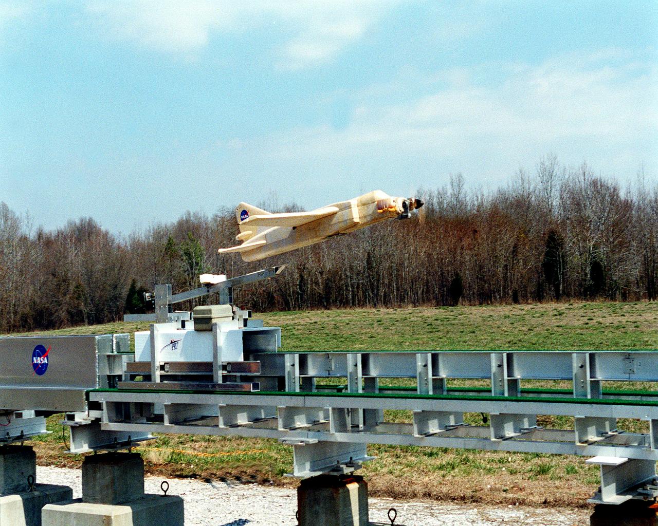
This image shows a 1/9 subscale model vehicle clearing the Magnetic Launch Assist System, formerly referred to as the Magnetic Levitation (MagLev), test track during a demonstration test conducted at the Marshall Space Flight Center (MSFC). Engineers at MSFC have developed and tested Magnetic Launch Assist technologies. To launch spacecraft into orbit, a Magnetic Launch Assist System would use magnetic fields to levitate and accelerate a vehicle along a track at very high speeds. Similar to high-speed trains and roller coasters that use high-strength magnets to lift and propel a vehicle a couple of inches above a guideway, a launch-assist system would electromagnetically drive a space vehicle along the track. A full-scale, operational track would be about 1.5-miles long and capable of accelerating a vehicle to 600 mph in 9.5 seconds. This track is an advanced linear induction motor. Induction motors are common in fans, power drills, and sewing machines. Instead of spinning in a circular motion to turn a shaft or gears, a linear induction motor produces thrust in a straight line. Mounted on concrete pedestals, the track is 100-feet long, about 2-feet wide and about 1.5-feet high. The major advantages of launch assist for NASA launch vehicles is that it reduces the weight of the take-off, the landing gear, the wing size, and less propellant resulting in significant cost savings. The US Navy and the British MOD (Ministry of Defense) are planning to use magnetic launch assist for their next generation aircraft carriers as the aircraft launch system. The US Army is considering using this technology for launching target drones for anti-aircraft training.

This image depicts a full view of the Earth, taken by the Geostationary Operational Environment Satellite (GOES-8). The red and green charnels represent visible data, while the blue channel represents inverted 11 micron infrared data. The north and south poles were not actually observed by GOES-8. To produce this image, poles were taken from a GOES-7 image. Owned and operated by the National Oceanic and Atmospheric Administration (NOAA), GOES satellites provide the kind of continuous monitoring necessary for intensive data analysis. They circle the Earth in a geosynchronous orbit, which means they orbit the equatorial plane of the Earth at a speed matching the Earth's rotation. This allows them to hover continuously over one position on the surface. The geosynchronous plane is about 35,800 km (22,300 miles) above the Earth, high enough to allow the satellites a full-disc view of the Earth. Because they stay above a fixed spot on the surface, they provide a constant vigil for the atmospheric triggers for severe weather conditions such as tornadoes, flash floods, hail storms, and hurricanes. When these conditions develop, the GOES satellites are able to monitor storm development and track their movements. NASA manages the design and launch of the spacecraft. NASA launched the first GOES for NOAA in 1975 and followed it with another in 1977. Currently, the United States is operating GOES-8, positioned at 75 west longitude and the equator, and GOES-10, which is positioned at 135 west longitude and the equator. (GOES-9, which malfunctioned in 1998, is being stored in orbit as an emergency backup should either GOES-8 or GOES-10 fail. GOES-11 was launched on May 3, 2000 and GOES-12 on July 23, 2001. Both are being stored in orbit as a fully functioning replacement for GOES-8 or GOES-10 on failure.

NASA’s X-59 quiet supersonic research aircraft accelerates down the runway Tuesday, Oct. 28, 2025, at U.S. Air Force Plant 42 in Palmdale, California, ahead of its first flight. This moment marks the start of flight testing for NASA’s Quesst mission, which aims to demonstrate quiet supersonic flight over land.

NASA’s X-59 quiet supersonic research aircraft accelerates down the runway Tuesday, Oct. 28, 2025, at U.S. Air Force Plant 42 in Palmdale, California, ahead of its first flight. This moment marks the start of flight testing for NASA’s Quesst mission, which aims to demonstrate quiet supersonic flight over land.

NASA’s X-59 quiet supersonic research aircraft accelerates down the runway Tuesday, Oct. 28, 2025, at U.S. Air Force Plant 42 in Palmdale, California, ahead of its first flight. This moment marks the start of flight testing for NASA’s Quesst mission, which aims to demonstrate quiet supersonic flight over land.

KENNEDY SPACE CENTER, FLA. - STS-115 Commander Brent Jett is dressed in his launch suit before flying the Shuttle Training Aircraft to practice landing the shuttle. STA practice is part of launch preparations. The STA is a Grumman American Aviation-built Gulf Stream II jet that was modified to simulate an orbiter’s cockpit, motion and visual cues, and handling qualities. In flight, the STA duplicates the orbiter’s atmospheric descent trajectory from approximately 35,000 feet altitude to landing on a runway. Because the orbiter is unpowered during re-entry and landing, its high-speed glide must be perfectly executed the first time. Mission STS-115 is scheduled to lift off about 12:29 p.m. Sept. 6. Mission managers cancelled Atlantis' first launch campaign due to a lightning strike at the pad and the passage of Tropical Storm Ernesto along Florida's east coast. The mission will deliver and install the 17-and-a-half-ton P3/P4 truss segment to the port side of the integrated truss system on the orbital outpost. The truss includes a new set of photovoltaic solar arrays. When unfurled to their full length of 240 feet, the arrays will provide additional power for the station in preparation for the delivery of international science modules over the next two years. STS-115 is expected to last 11 days and includes three scheduled spacewalks. Photo credit: NASA/Kim Shiflett
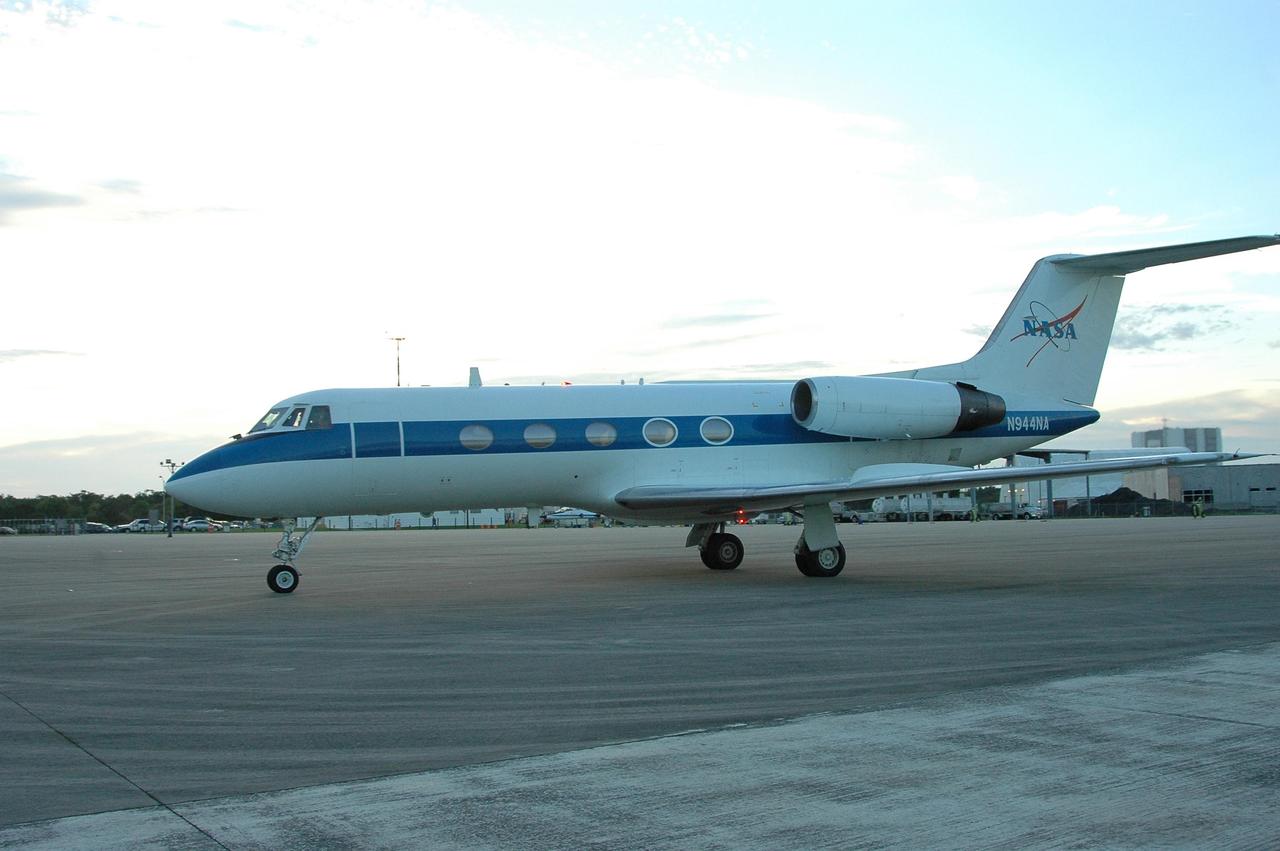
KENNEDY SPACE CENTER, FLA. - A Shuttle Training Aircraft (STA) taxis into the parking area of KSC's Shuttle Landing Facility. In the specially configured aircraft, STS-115 Commander Brent Jett and Pilot Christopher Ferguson practiced landing the shuttle this morning. STA practice is part of launch preparations. The STA is a Grumman American Aviation-built Gulf Stream II jet that was modified to simulate an orbiter’s cockpit, motion and visual cues, and handling qualities. In flight, the STA duplicates the orbiter’s atmospheric descent trajectory from approximately 35,000 feet altitude to landing on a runway. Because the orbiter is unpowered during re-entry and landing, its high-speed glide must be perfectly executed the first time. Mission STS-115 is scheduled to lift off about 12:29 p.m. Sept. 6. Mission managers cancelled Atlantis' first launch campaign due to a lightning strike at the pad and the passage of Tropical Storm Ernesto along Florida's east coast. The mission will deliver and install the 17-and-a-half-ton P3/P4 truss segment to the port side of the integrated truss system on the orbital outpost. The truss includes a new set of photovoltaic solar arrays. When unfurled to their full length of 240 feet, the arrays will provide additional power for the station in preparation for the delivery of international science modules over the next two years. STS-115 is expected to last 11 days and includes three scheduled spacewalks. Photo credit: NASA/Kim Shiflett