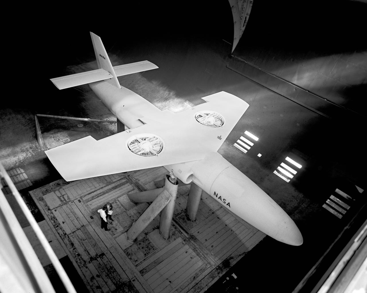
Top view if GE fan model, 3/4 top view. Straight wing. 1 fan per wing, conventional struts. Woody Kook, Branch Chief.
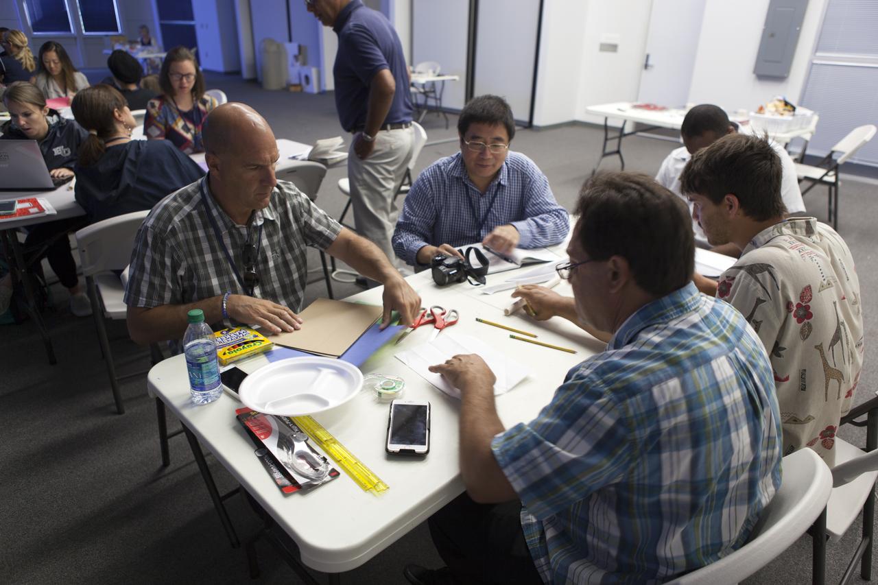
Teachers prepare to demonstrate the projects they built for the Rocketry Engineering Design Challenge during the 2017 GE Foundation High School STEM Integration Conference at the Center for Space Education at NASA's Kennedy Space Center. High school teachers from across the country took part in the week-long conference, which is designed to explore effective ways for teachers, schools and districts from across the country to integrate STEM throughout the curriculum. The conference is a partnership between GE Foundation and the National Science Teachers Association.

Teachers prepare to demonstrate the projects they built for the Rocketry Engineering Design Challenge during the 2017 GE Foundation High School STEM Integration Conference at the Center for Space Education at NASA's Kennedy Space Center. High school teachers from across the country took part in the week-long conference, which is designed to explore effective ways for teachers, schools and districts from across the country to integrate STEM throughout the curriculum. The conference is a partnership between GE Foundation and the National Science Teachers Association.

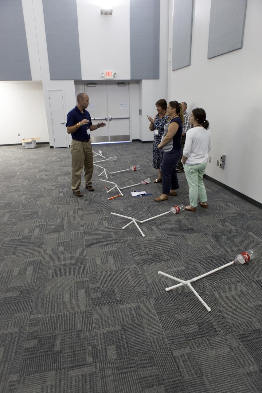
Teachers participate in the Rocketry Engineering Design Challenge during the 2017 GE Foundation High School STEM Integration Conference at the Center for Space Education at NASA's Kennedy Space Center. High school teachers from across the country took part in the week-long conference, which is designed to explore effective ways for teachers, schools and districts from across the country to integrate STEM throughout the curriculum. The conference is a partnership between GE Foundation and the National Science Teachers Association.

Teachers participate in the Rocketry Engineering Design Challenge during the 2017 GE Foundation High School STEM Integration Conference at the Center for Space Education at NASA's Kennedy Space Center. High school teachers from across the country took part in the week-long conference, which is designed to explore effective ways for teachers, schools and districts from across the country to integrate STEM throughout the curriculum. The conference is a partnership between GE Foundation and the National Science Teachers Association.
Teachers participate in the Rocketry Engineering Design Challenge during the 2017 GE Foundation High School STEM Integration Conference at the Center for Space Education at NASA's Kennedy Space Center. High school teachers from across the country took part in the week-long conference, which is designed to explore effective ways for teachers, schools and districts from across the country to integrate STEM throughout the curriculum. The conference is a partnership between GE Foundation and the National Science Teachers Association.
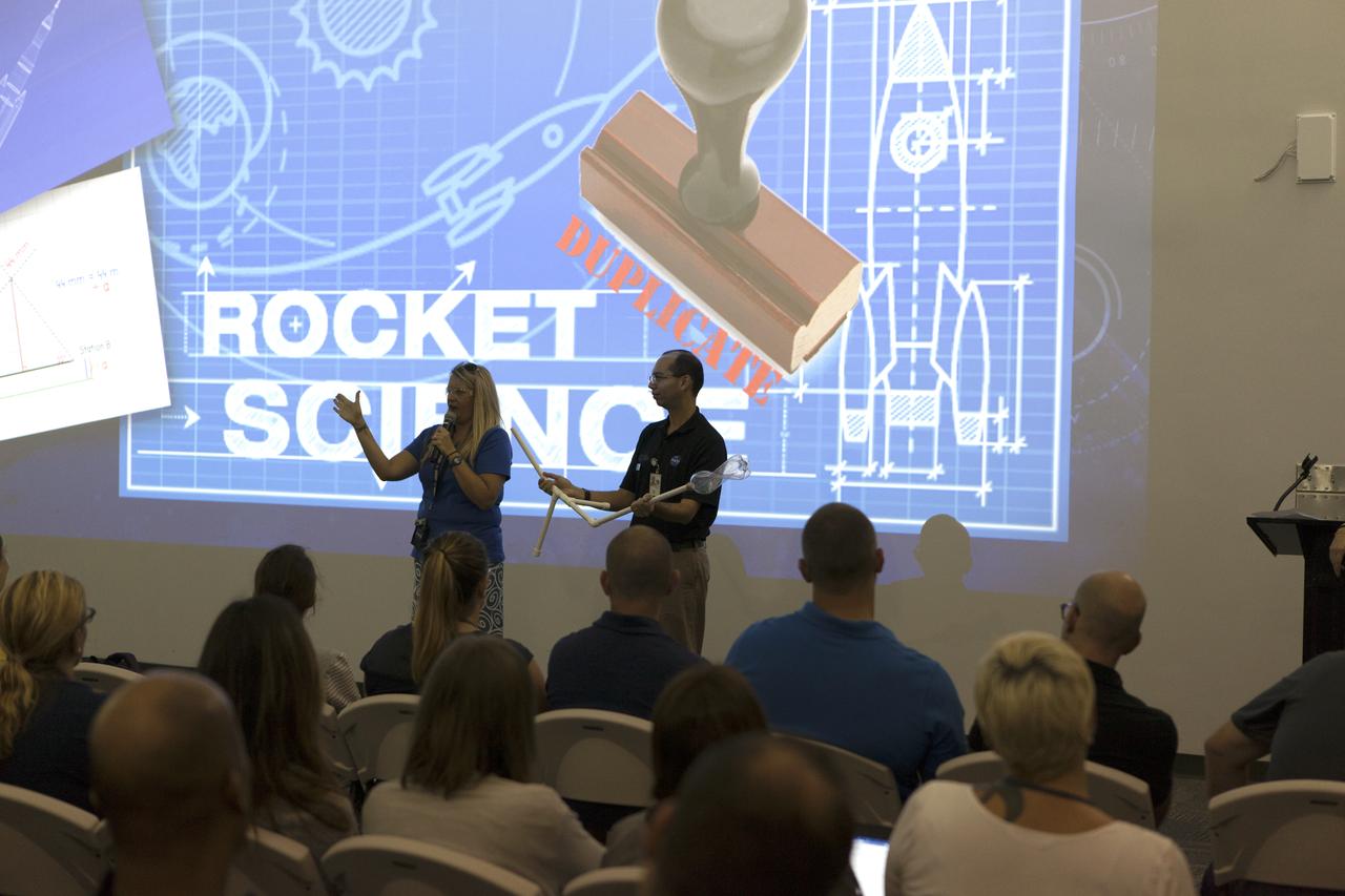
Education Specialists Lynn Dotson, left, of the NASA Public Engagement Center, and Lester Morales, right, of Texas State University's NASA STEM Educator Professional Development Collaborative, explain the Rocketry Engineering Design Challenge to teachers participating in the 2017 GE Foundation High School STEM Integration Conference at the Center for Space Education at NASA's Kennedy Space Center. High school teachers from across the country took part in the week-long conference, which is designed to explore effective ways for teachers, schools and districts from across the country to integrate STEM throughout the curriculum. The conference is a partnership between GE Foundation and the National Science Teachers Association.
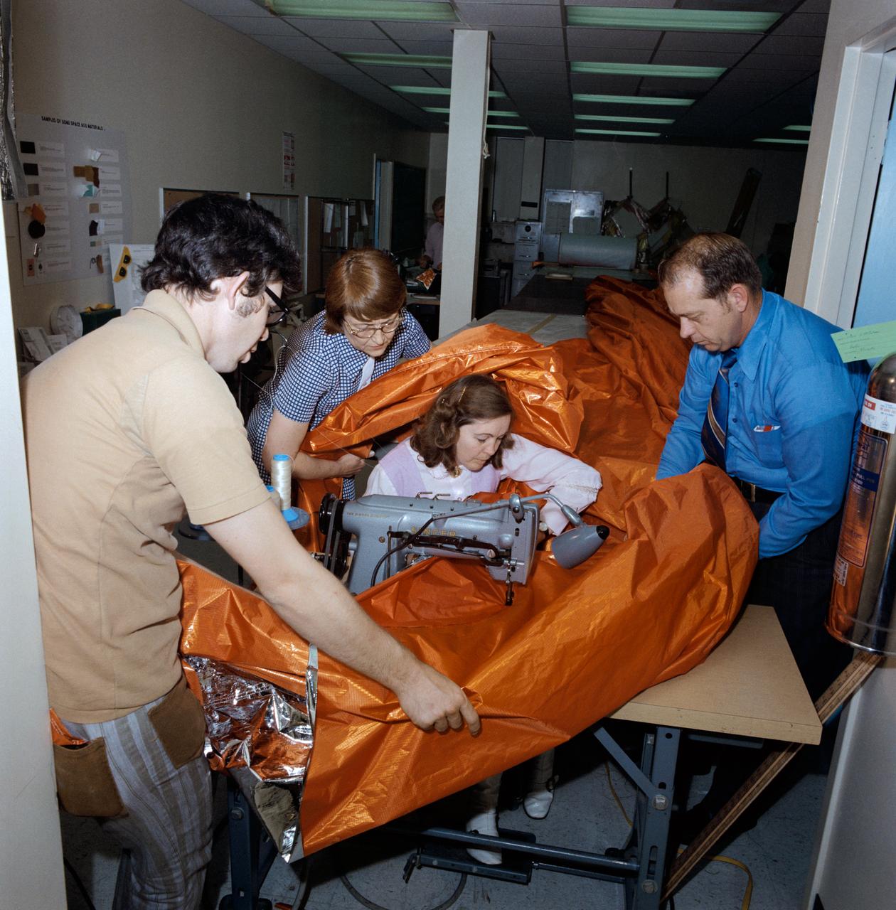
S73-26047 (18 May 1973) --- A sail-like sunshade for possible use as a sunscreen for the Skylab orbital workshop (OWS) is shown being fabricated in the GE Building across the street from the Johnson Space Center. Three persons assist the seamstress feed the material through the sewing machine. The three-layered shade will be composed of a top layer of aluminum Mylar, a middle layer of laminated nylon rip stop, and a bottom layer of thin nylon. Working on the sunshade, from left to right, are Dale Gentry, Elizabeth Gauldin, Alyene Baker and James H. Barnett Jr. Mrs. Baker, a GE employee, operates the double-needle sewing machine. Barnett is head of the Crew Equipment Development Section of JSC's Crew Systems Division. Mrs. Gauldin is also with the Crew Systems Division. Gentry works for GE. The work shown here is part of the crash program underway to prepare a protection device for Skylab to replace the original shield which was lost when the unmanned Skylab 1 launch took place on May 14, 1973. The improvised solar shield selected to be used will be carried to Earth orbit by the Skylab 2 crew, who will deploy it to shade part of the OWS from the hot rays of the sun. Loss of the original shield, as expected, has caused an overheating problem on the OWS. Photo credit: NASA
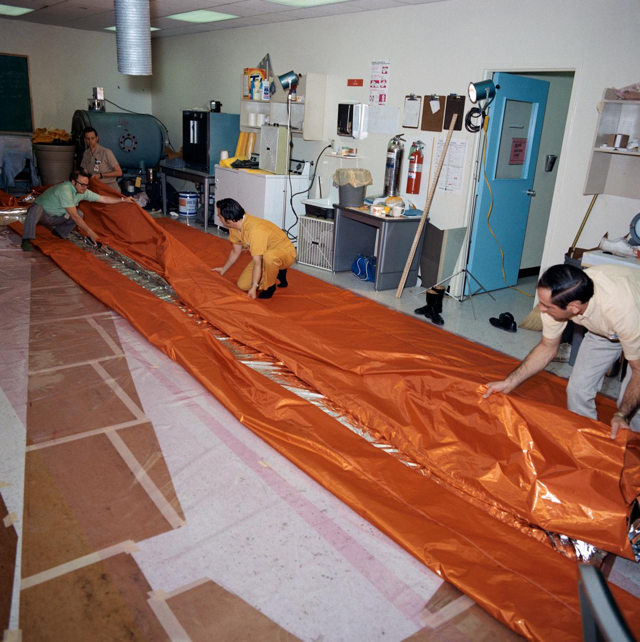
S73-26046 (18 May 1973) --- Workmen in the GE Building across the street from the Johnson Space Center fold a sail-like sunshade being fabricated for possible use as a sunscreen for the Skylab Orbital Workshop (OWS). The three-layered sunshade will be composed of a top layer of aluminized mylar, a middle layer of laminated nylon rip-stop, and a bottom layer of thin nylon. The men are, left to right, Gerry E. Wood (wearing glasses), Glenn Hewitt, Pat Morrow, and Fred Le Donne. Wood is manager of crew provisions and engineering at GE. The work shown here is part of the crash program now underway to prepare a sunshield for Skylab to replace the original shield which was lost when Skylab I was launched on May 14, 1973. The improvised solar shield selected to be used will be carried to Earth orbit by the Skylab 2 crewmen who will deploy it to shade part of the OWS from the hot rays of the sun. Loss of the original shield has caused an overheating problem in the OWS. Photo credit: NASA
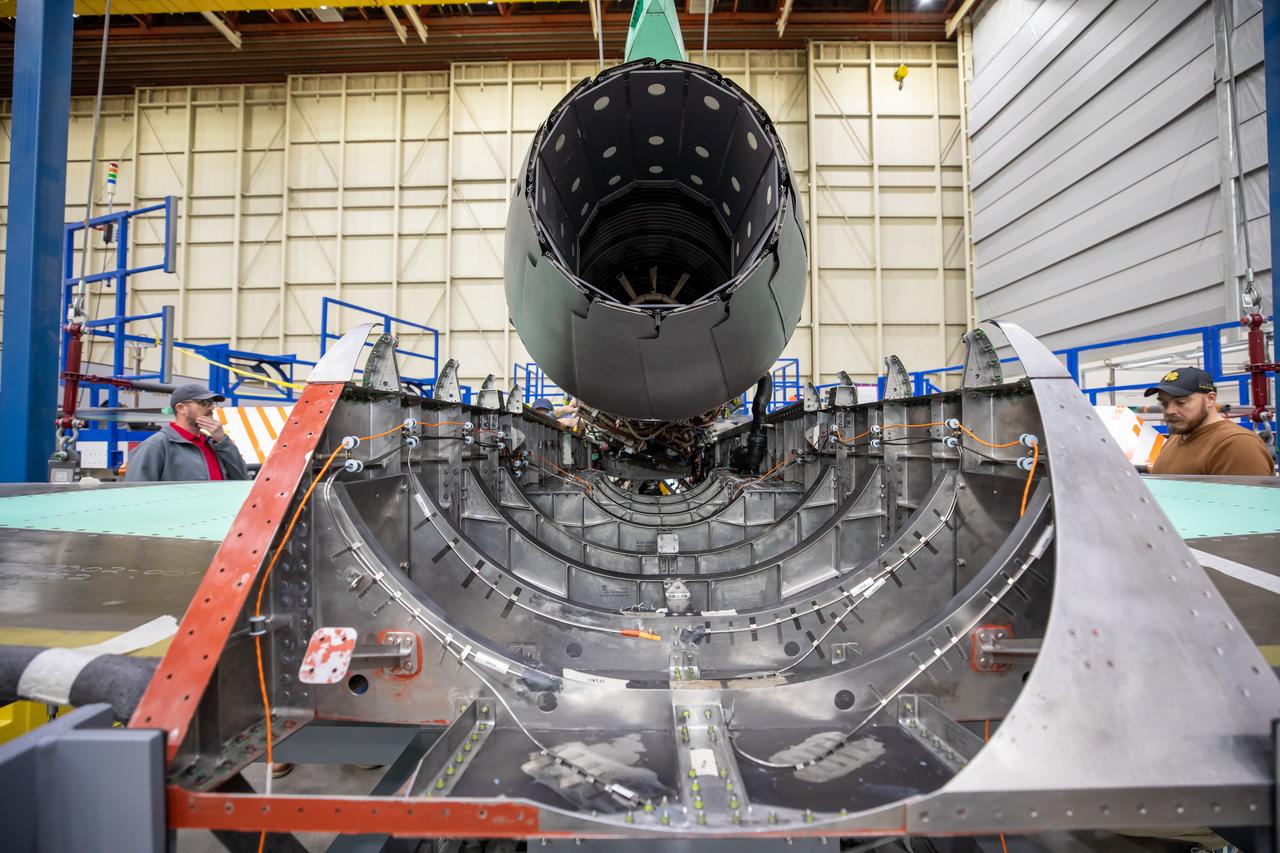
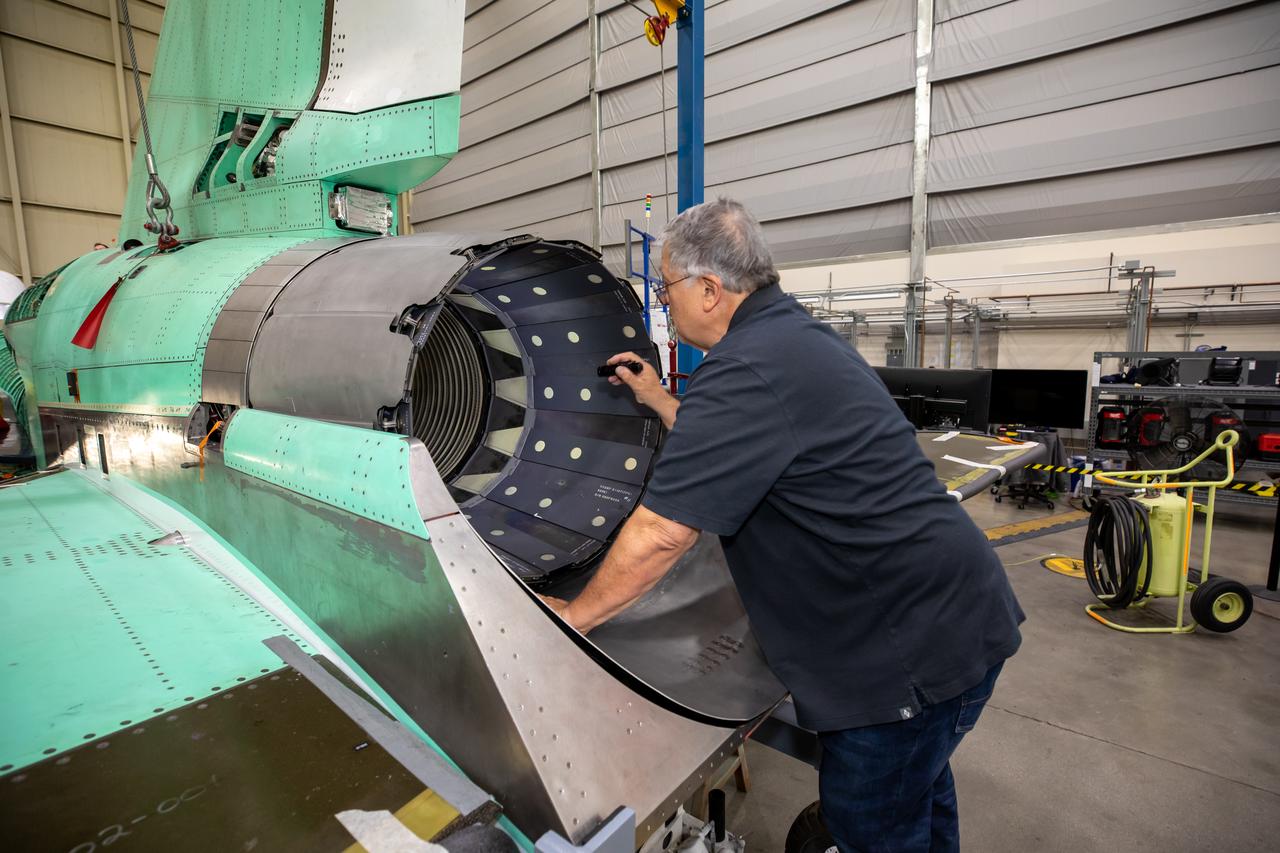
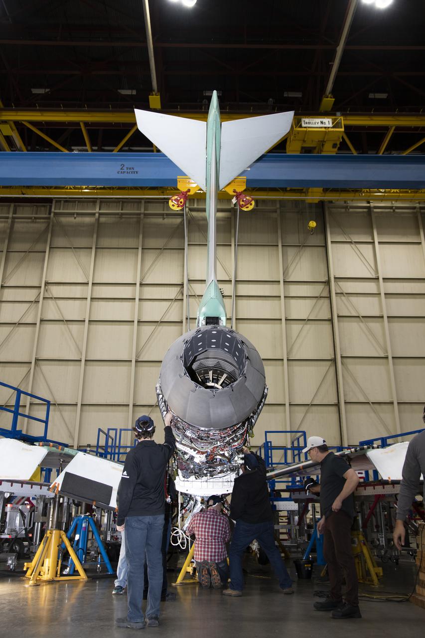
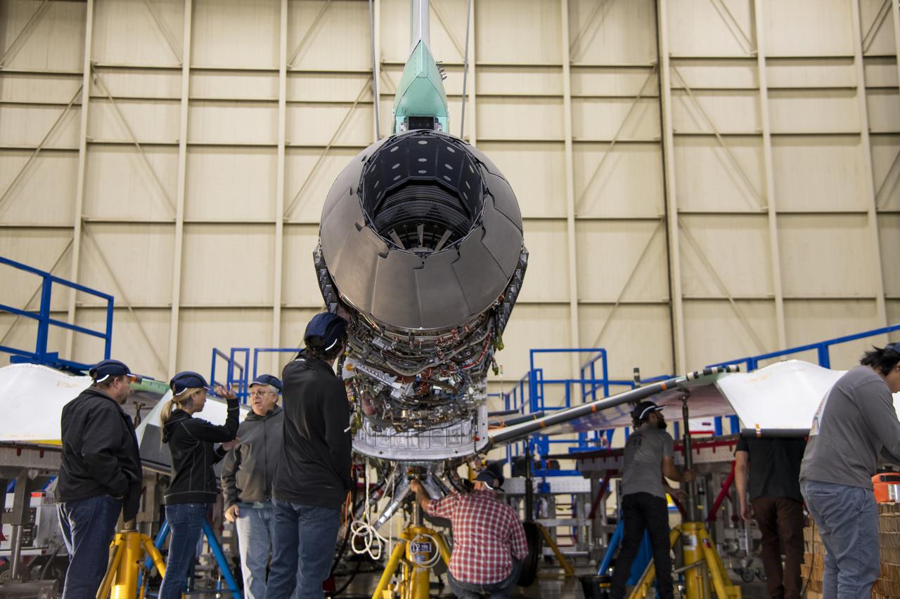
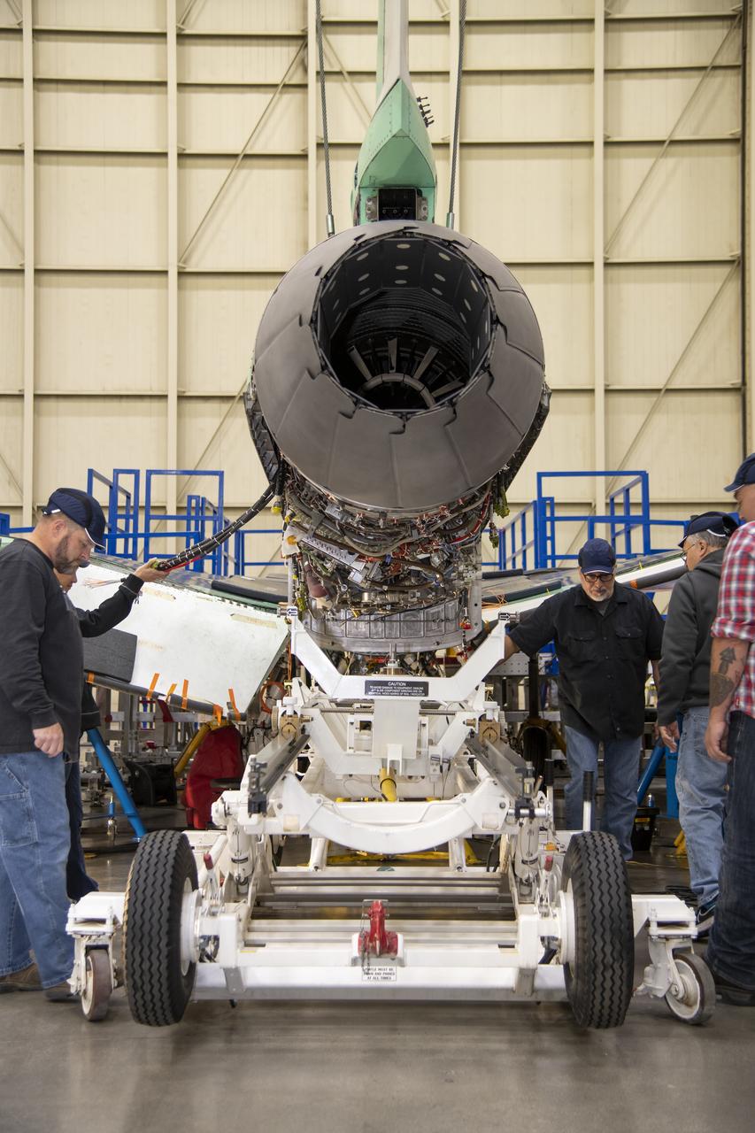
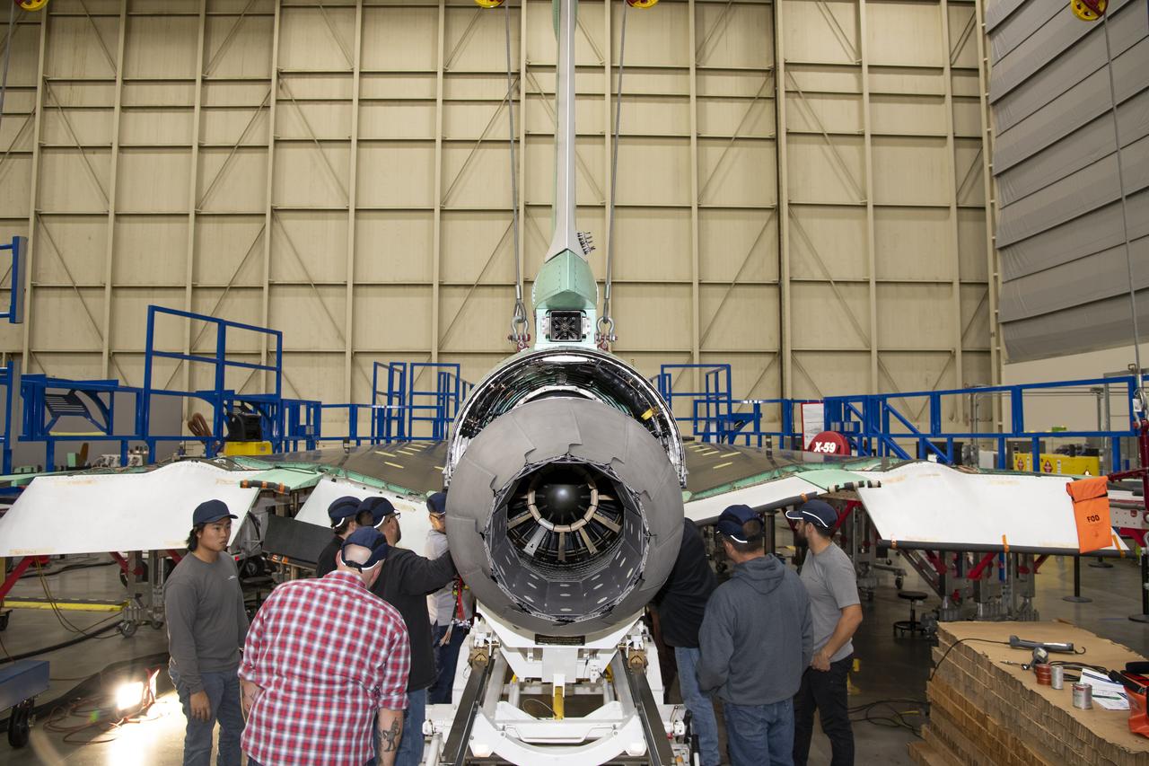
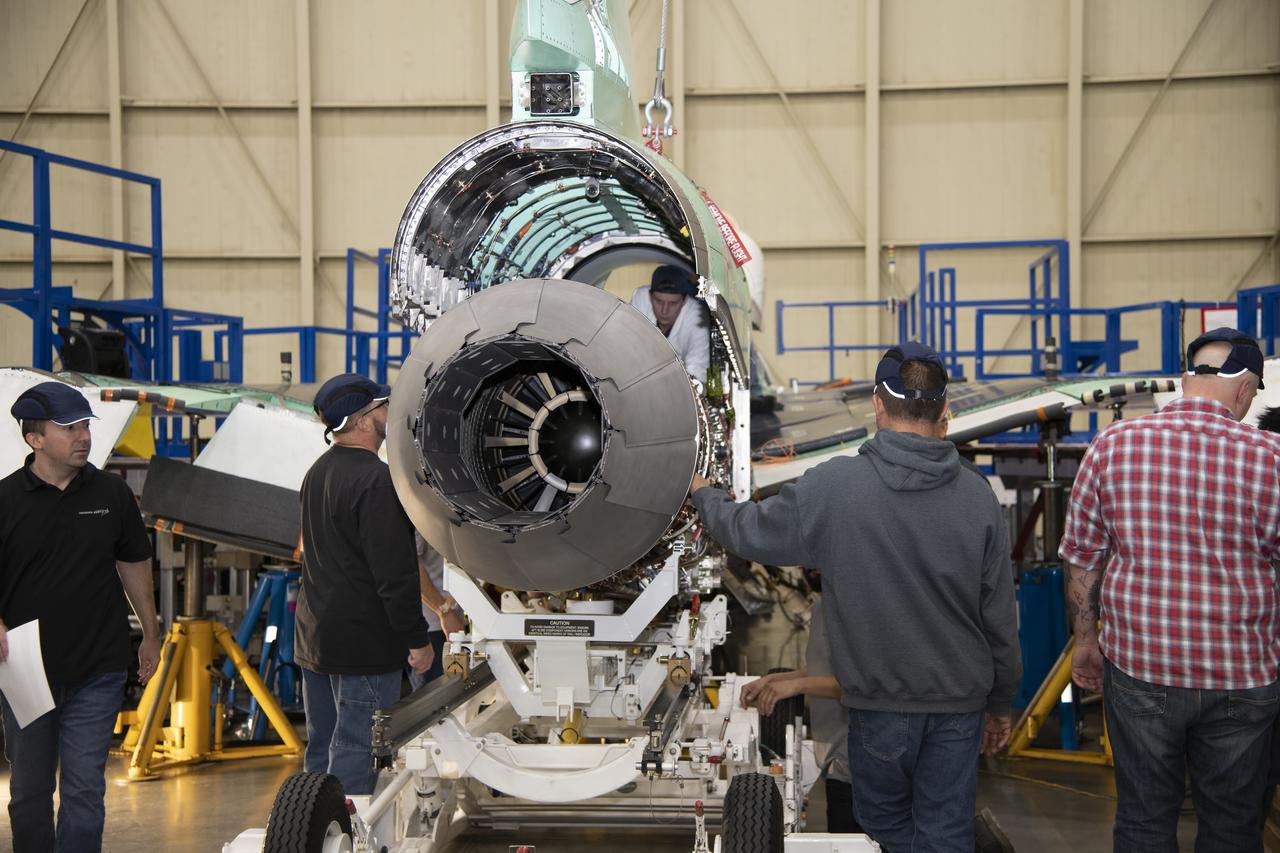
Here is a close-up of the GE F414 engine, from the aft deck or rear, before the tail section of the X-59 is lifted into place and attached to the aircraft. The aft deck helps control the shockwaves at the end of the aircraft and reduce the noise of a sonic boom to more of a sonic thump.
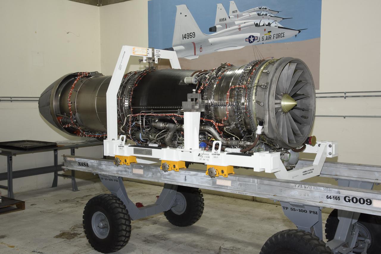
The F414-GE-100 engine, which will power NASA’s X-59 Quiet SuperSonic Technology X-plane (QueSST) in flight, is unboxed at NASA’s Armstrong Flight Research Center in Edwards, California. The engine, one of two delivered by GE, is approximately 13 feet long, and will power X-59 on missions to gather information about how the public perceives the sounds of quieter supersonic flight.

The F414-GE-100 engine, which will power NASA’s X-59 Quiet SuperSonic Technology X-plane (QueSST) in flight, is unboxed at NASA’s Armstrong Flight Research Center in Edwards, California. The engine, one of two delivered by GE, is approximately 13 feet long, and will power X-59 on missions to gather information about how the public perceives the sounds of quieter supersonic flight.
REMOVAL OF GE - GENERAL ELECTRIC - DRIVERS
REMOVAL OF GE - GENERAL ELECTRIC - DRIVERS

GENERAL ELECTRIC GE 2 CUP SECTOR

PSL CONTROL ROOM TEST ENGINEERS AND OPERATORS GE J85 TBCC ENGINE TEST TURBINE BASED COMBINED CYCLE
A quality inspector inspects the GE F-414 engine nozzle after installation at Lockheed Martin’s Skunk Works facility in Palmdale, California. Once the aircraft and ground testing are complete, the X-59 will undergo flight testing, which will demonstrate the plane’s ability to fly supersonic - faster than the speed of sound - while reducing the loud sonic boom. This could enable commercial supersonic air travel over land.
The engine that will power NASA’s quiet supersonic X-59 in flight is installed, marking a major milestone in the experimental aircraft’s journey toward first flight. The installation of the F414-GE-100 engine at Lockheed Martin’s Skunk Works facility brings the vehicle close to the completion of its assembly.
The engine that will power NASA’s quiet supersonic X-59 in flight is installed, marking a major milestone in the experimental aircraft’s journey toward first flight. The installation of the F414-GE-100 engine at Lockheed Martin’s Skunk Works facility brings the vehicle close to the completion of its assembly.
The engine that will power NASA’s quiet supersonic X-59 in flight is installed, marking a major milestone in the experimental aircraft’s journey toward first flight. The installation of the F414-GE-100 engine at Lockheed Martin’s Skunk Works facility brings the vehicle close to the completion of its assembly.
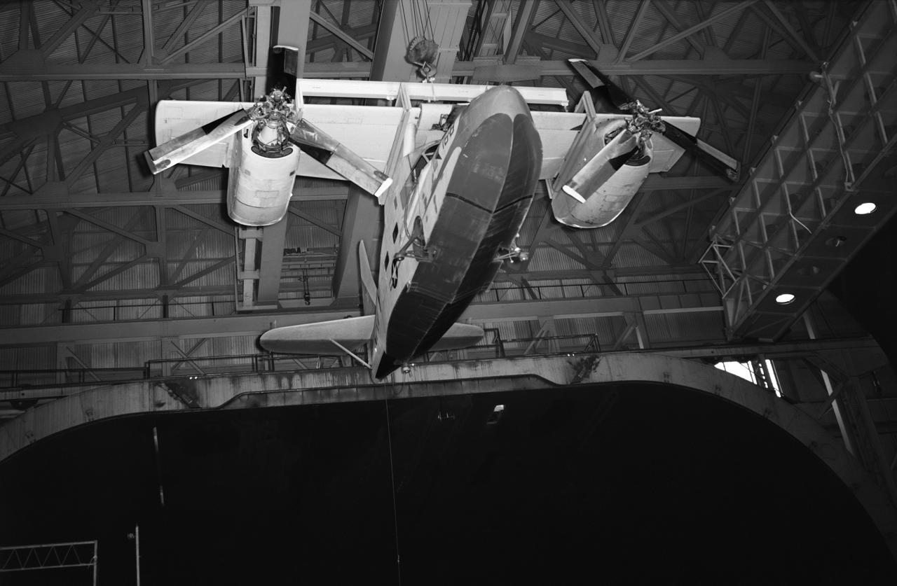
Test No. 175 Kaman K-16 being lowered into the 40x80 foot wind tunnel at NASA's Ames Research Center, viewed from the front. Kaman K-16B was an experimental tilt wing aircraft, it used the fuselage of a JRF-5 and was powered by two General Electric YT58-GE-2A engines.
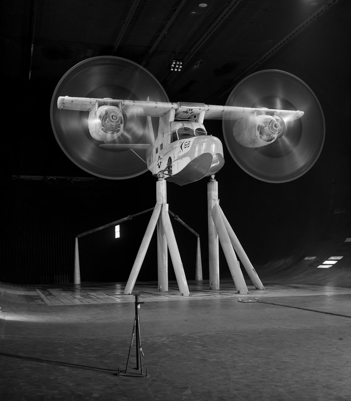
Test No. 175 Kaman K-16 in 40x80 Foot Wind Tunnel at Ames Research Center. Kaman K-16B was an experimental tilt wing aircraft, it used the fuselage of a JRF-5 and was powered by two General Electric YT58-GE-2A engines.
The engine that will power NASA’s quiet supersonic X-59 in flight is installed, marking a major milestone in the experimental aircraft’s journey toward first flight. The installation of the F414-GE-100 engine at Lockheed Martin’s Skunk Works facility brings the vehicle close to the completion of its assembly.
The engine that will power NASA’s quiet supersonic X-59 in flight is installed, marking a major milestone in the experimental aircraft’s journey toward first flight. The installation of the F414-GE-100 engine at Lockheed Martin’s Skunk Works facility brings the vehicle close to the completion of its assembly.
The engine that will power NASA's quiet supersonic X-59 in flight is installed, marking a major milestone in the experimental aircraft's journey toward first flight. The installation of the F414-GE-100 engine at Lockheed Martin's Skunk Works facility brings the vehicle close to the completion of its assembly.

The engine that will power NASA’s quiet supersonic X-59 in flight is installed, marking a major milestone in the experimental aircraft’s journey toward first flight. The installation of the F414-GE-100 engine at Lockheed Martin’s Skunk Works facility brings the vehicle close to the completion of its assembly.
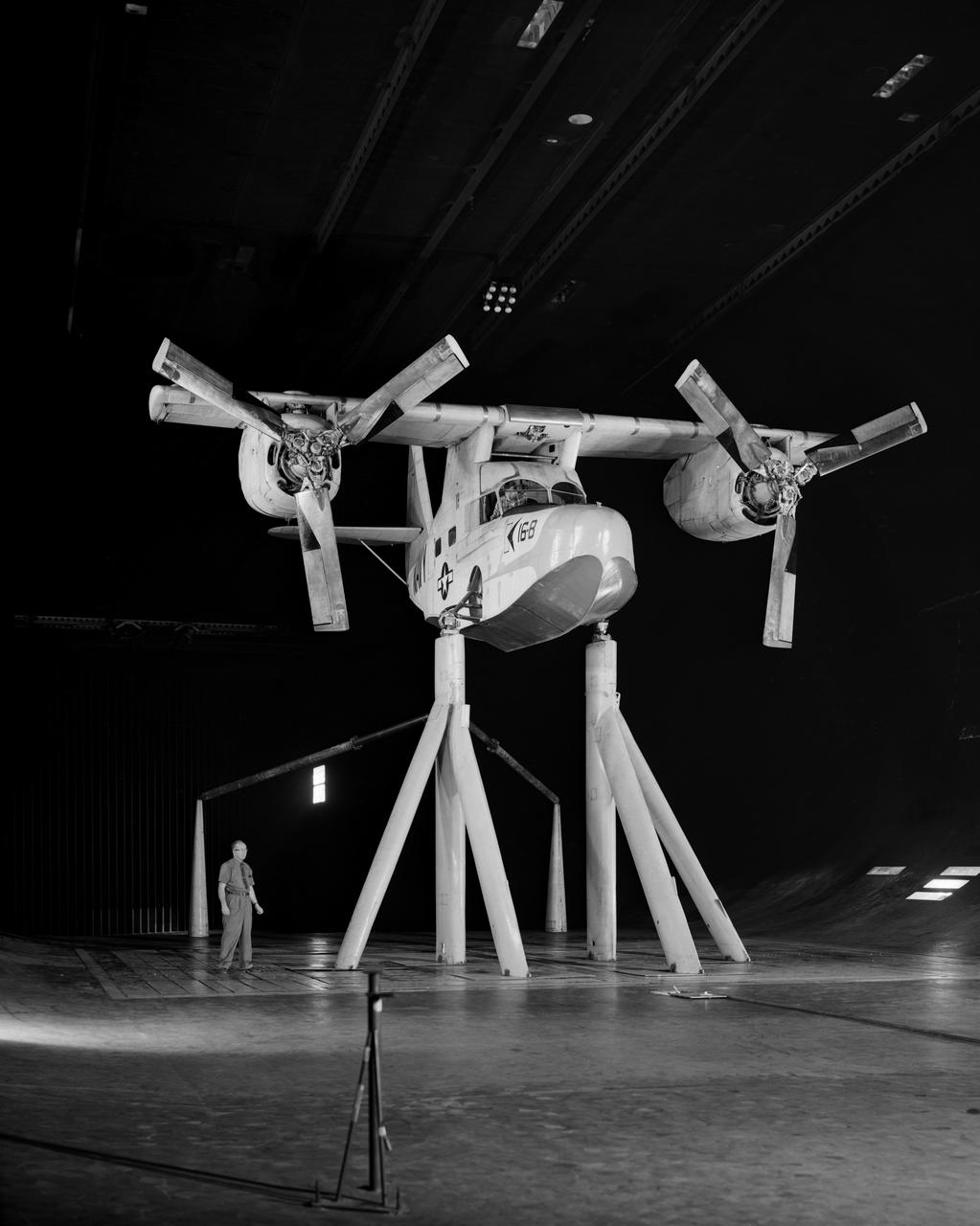
Test No. 175 Kaman K-16 in 40x80 Foot Wind Tunnel at Ames Research Center. Pictured with two Kaman employees. 3/4 Front view of Airplane. Kaman K-16B was an experimental tilt wing aircraft, it used the fuselage of a JRF-5 and was powered by two General Electric YT58-GE-2A engines.
The engine that will power NASA's quiet supersonic X-59 in flight is installed, marking a major milestone in the experimental aircraft's journey toward first flight. The installation of the F414-GE-100 engine at Lockheed Martin's Skunk Works facility brings the vehicle close to the completion of its assembly.
The engine that will power NASA’s quiet supersonic X-59 in flight is installed, marking a major milestone in the experimental aircraft’s journey toward first flight. The installation of the F414-GE-100 engine at Lockheed Martin’s Skunk Works facility brings the vehicle close to the completion of its assembly.
The engine that will power NASA’s quiet supersonic X-59 in flight is installed, marking a major milestone in the experimental aircraft’s journey toward first flight. The installation of the F414-GE-100 engine at Lockheed Martin’s Skunk Works facility brings the vehicle close to the completion of its assembly.
The engine that will power NASA’s quiet supersonic X-59 in flight is installed, marking a major milestone in the experimental aircraft’s journey toward first flight. The installation of the F414-GE-100 engine at Lockheed Martin’s Skunk Works facility brings the vehicle close to the completion of its assembly.
The engine that will power NASA’s quiet supersonic X-59 in flight is installed, marking a major milestone in the experimental aircraft’s journey toward first flight. The installation of the F414-GE-100 engine at Lockheed Martin’s Skunk Works facility brings the vehicle close to the completion of its assembly.

The engine that will power NASA’s quiet supersonic X-59 in flight is installed, marking a major milestone in the experimental aircraft’s journey toward first flight. The installation of the F414-GE-100 engine at Lockheed Martin’s Skunk Works facility brings the vehicle close to the completion of its assembly.
The engine that will power NASA’s quiet supersonic X-59 in flight is installed, marking a major milestone in the experimental aircraft’s journey toward first flight. The installation of the F414-GE-100 engine at Lockheed Martin’s Skunk Works facility brings the vehicle close to the completion of its assembly.
The engine that will power NASA's quiet supersonic X-59 in flight is installed, marking a major milestone in the experimental aircraft's journey toward first flight. The installation of the F414-GE-100 engine at Lockheed Martin's Skunk Works facility brings the vehicle close to the completion of its assembly.
The engine that will power NASA's quiet supersonic X-59 in flight is installed, marking a major milestone in the experimental aircraft's journey toward first flight. The installation of the F414-GE-100 engine at Lockheed Martin's Skunk Works facility brings the vehicle close to the completion of its assembly.
The engine that will power NASA’s quiet supersonic X-59 in flight is installed, marking a major milestone in the experimental aircraft’s journey toward first flight. The installation of the F414-GE-100 engine at Lockheed Martin’s Skunk Works facility brings the vehicle close to the completion of its assembly.
The engine that will power NASA’s quiet supersonic X-59 in flight is installed, marking a major milestone in the experimental aircraft’s journey toward first flight. The installation of the F414-GE-100 engine at Lockheed Martin’s Skunk Works facility brings the vehicle close to the completion of its assembly.
The engine that will power NASA’s quiet supersonic X-59 in flight is installed, marking a major milestone in the experimental aircraft’s journey toward first flight. The installation of the F414-GE-100 engine at Lockheed Martin’s Skunk Works facility brings the vehicle close to the completion of its assembly.
The engine that will power NASA’s quiet supersonic X-59 in flight is installed, marking a major milestone in the experimental aircraft’s journey toward first flight. The installation of the F414-GE-100 engine at Lockheed Martin’s Skunk Works facility brings the vehicle close to the completion of its assembly.
The engine that will power NASA’s quiet supersonic X-59 in flight is installed, marking a major milestone in the experimental aircraft’s journey toward first flight. The installation of the F414-GE-100 engine at Lockheed Martin’s Skunk Works facility brings the vehicle close to the completion of its assembly.
The engine that will power NASA’s quiet supersonic X-59 in flight is installed, marking a major milestone in the experimental aircraft’s journey toward first flight. The installation of the F414-GE-100 engine at Lockheed Martin’s Skunk Works facility brings the vehicle close to the completion of its assembly.
The engine that will power NASA’s quiet supersonic X-59 in flight is installed, marking a major milestone in the experimental aircraft’s journey toward first flight. The installation of the F414-GE-100 engine at Lockheed Martin’s Skunk Works facility brings the vehicle close to the completion of its assembly.
The engine that will power NASA’s quiet supersonic X-59 in flight is installed, marking a major milestone in the experimental aircraft’s journey toward first flight. The installation of the F414-GE-100 engine at Lockheed Martin’s Skunk Works facility brings the vehicle close to the completion of its assembly.
The engine that will power NASA’s quiet supersonic X-59 in flight is installed, marking a major milestone in the experimental aircraft’s journey toward first flight. The installation of the F414-GE-100 engine at Lockheed Martin’s Skunk Works facility brings the vehicle close to the completion of its assembly.

The engine that will power NASA’s quiet supersonic X-59 in flight is installed, marking a major milestone in the experimental aircraft’s journey toward first flight. The installation of the F414-GE-100 engine at Lockheed Martin’s Skunk Works facility brings the vehicle close to the completion of its assembly.
The engine that will power NASA’s quiet supersonic X-59 in flight is installed, marking a major milestone in the experimental aircraft’s journey toward first flight. The installation of the F414-GE-100 engine at Lockheed Martin’s Skunk Works facility brings the vehicle close to the completion of its assembly.
The engine that will power NASA’s quiet supersonic X-59 in flight is installed, marking a major milestone in the experimental aircraft’s journey toward first flight. The installation of the F414-GE-100 engine at Lockheed Martin’s Skunk Works facility brings the vehicle close to the completion of its assembly.
This is an up-close view of the X-59’s engine inlet – fresh after being painted. The 13-foot F414-GE-100 engine will be placed inside the inlet bringing the X-59 aircraft one step closer to completion. Once fully assembled, the X-59 aircraft will begin flight operations, working toward demonstration of the ability to fly supersonic while reducing the loud sonic boom to a quiet sonic thump, helping to enable commercial supersonic air travel over land.
3/4 front view VZ-11 ground test - variable height struts. Engines of the VZ-11 are a pair of General Electric J85-5 turbojets, mounted in high in the centre fuselage, well away from fan disturbance. Designed in the Ames 40x80 foot wind tunnel.
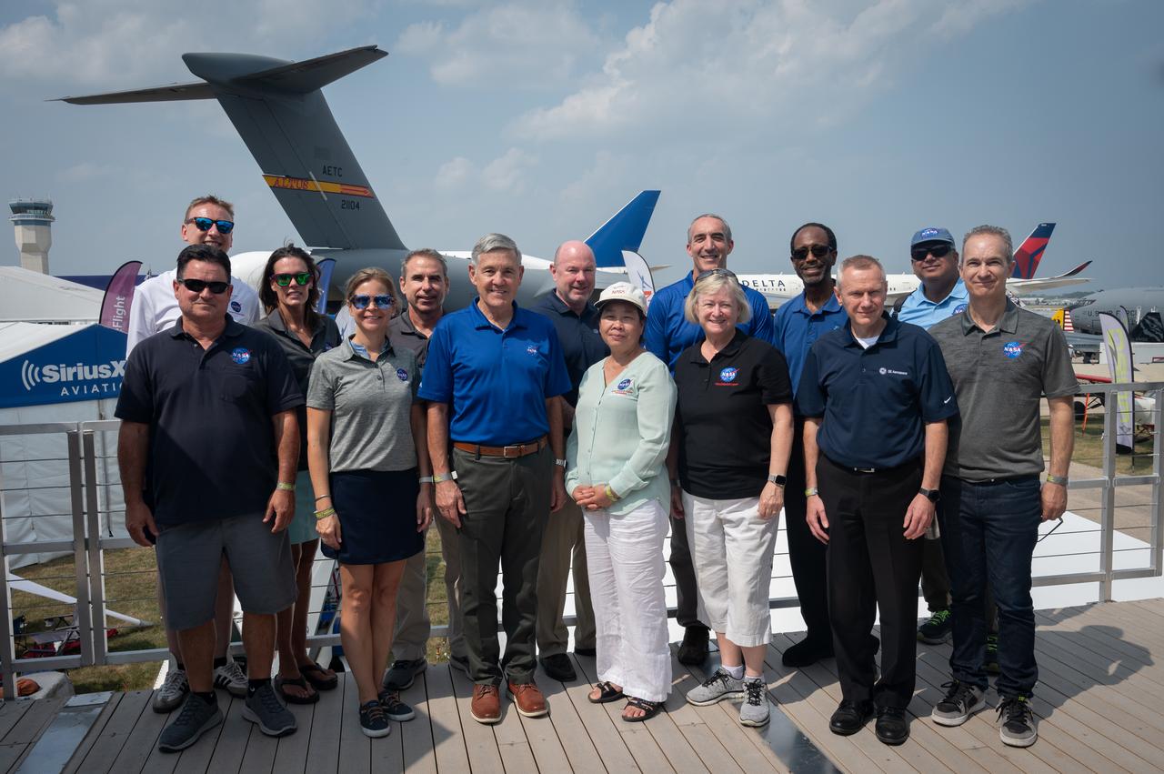
AirVenture at Oshkosh 2023
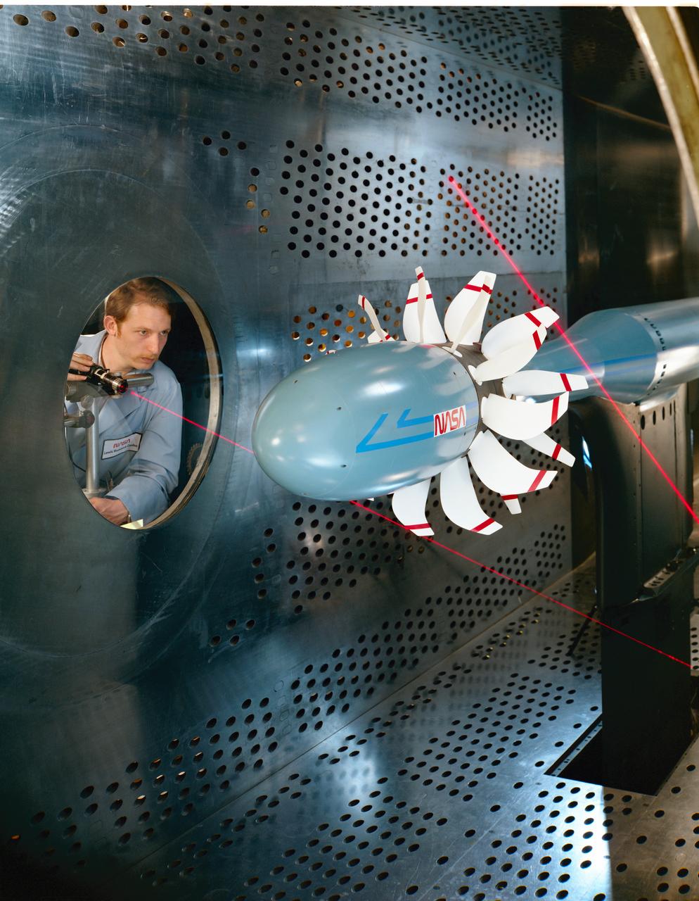
Laser based blade deflection measurement system on Counter Rotation Pusher Propeller model in 8x6 SWT (Supersonic Wind Tunnel)
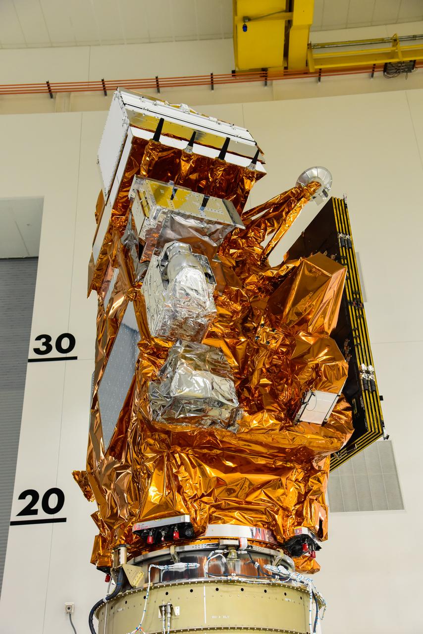
The National Oceanic and Atmospheric Administration’s (NOAA) Joint Polar Satellite System-2 (JPSS-2) is in view inside the Astrotech Space Operations facility at Vandenberg Space Force Base (VSFB) in California on Oct. 12, 2022. JPSS-2 is being prepared for encapsulation inside United Launch Alliance Atlas V payload fairing. The satellite is stacked atop NASA’s Low-Earth Orbit Flight Test of an Inflatable Decelerator (LOFTID) secondary payload. JPSS-2 is the third satellite in the Joint Polar Satellite System series. It is scheduled to lift off from VSFB on Nov. 1 from Space Launch Complex-3. JPSS-2, which will be renamed NOAA-21 after reaching orbit, will join a constellation of JPSS satellites that orbit from the North to the South pole, circling Earth 14 times a day and providing a full view of the entire globe twice daily. The NOAA/NASA Suomi National Polar-orbiting Partnership (Suomi NPP) satellite, and NOAA-20, previously known as JPSS-1, are both already in orbit. Each satellite carries at least four advanced instruments to measure weather and climate conditions on Earth. LOFTID is dedicated to the memory of Bernard Kutter. LOFTID will demonstrate inflatable heat shield technology that could enable a variety of proposed NASA missions to destinations such as Mars, Venus, and Titan, as well as returning heavier payloads from low-Earth orbit.
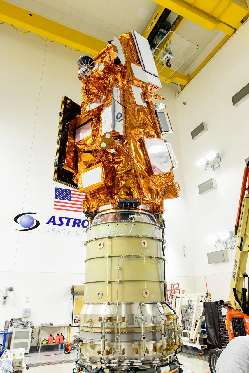
The National Oceanic and Atmospheric Administration’s (NOAA) Joint Polar Satellite System-2 (JPSS-2), stacked atop NASA’s Low-Earth Orbit Flight Test of an Inflatable Decelerator (LOFTID) secondary payload is in view inside the Astrotech Space Operations facility at Vandenberg Space Force Base (VSFB) in California on Oct. 12, 2022. JPSS-2 is being prepared for encapsulation inside the United Launch Alliance Atlas V payload fairing. JPSS-2 is the third satellite in the Joint Polar Satellite System series. It is scheduled to lift off from VSFB on Nov. 1 from Space Launch Complex-3. JPSS-2, which will be renamed NOAA-21 after reaching orbit, will join a constellation of JPSS satellites that orbit from the North to the South pole, circling Earth 14 times a day and providing a full view of the entire globe twice daily. The NOAA/NASA Suomi National Polar-orbiting Partnership (Suomi NPP) satellite, and NOAA-20, previously known as JPSS-1, are both already in orbit. Each satellite carries at least four advanced instruments to measure weather and climate conditions on Earth. LOFTID is dedicated to the memory of Bernard Kutter. LOFTID will demonstrate inflatable heat shield technology that could enable a variety of proposed NASA missions to destinations such as Mars, Venus, and Titan, as well as returning heavier payloads from low-Earth orbit.

Technicians move the National Oceanic and Atmospheric Administration’s (NOAA) Joint Polar Satellite System-2 (JPSS-2), stacked atop NASA’s Low-Earth Orbit Flight Test of an Inflatable Decelerator (LOFTID) secondary payload into the first half of the United Launch Alliance Atlas V payload fairing inside the Astrotech Space Operations facility at Vandenberg Space Force Base (VSFB) in California on Oct. 12, 2022. JPSS-2 is the third satellite in the Joint Polar Satellite System series. It is scheduled to lift off from VSFB on Nov. 1 from Space Launch Complex-3. JPSS-2, which will be renamed NOAA-21 after reaching orbit, will join a constellation of JPSS satellites that orbit from the North to the South pole, circling Earth 14 times a day and providing a full view of the entire globe twice daily. The NOAA/NASA Suomi National Polar-orbiting Partnership (Suomi NPP) satellite, and NOAA-20, previously known as JPSS-1, are both already in orbit. Each satellite carries at least four advanced instruments to measure weather and climate conditions on Earth. LOFTID is dedicated to the memory of Bernard Kutter. LOFTID will demonstrate inflatable heat shield technology that could enable a variety of proposed NASA missions to destinations such as Mars, Venus, and Titan, as well as returning heavier payloads from low-Earth orbit.
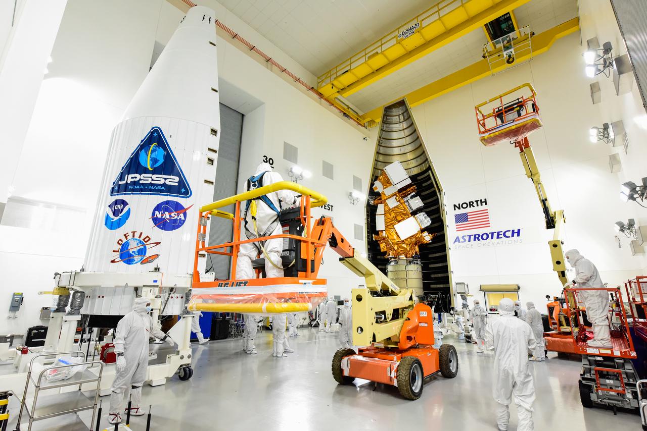
Technicians prepare to move the second half of the United Launch Alliance Atlas V payload fairing around the National Oceanic and Atmospheric Administration’s (NOAA) Joint Polar Satellite System-2 (JPSS-2), stacked atop NASA’s Low-Earth Orbit Flight Test of an Inflatable Decelerator (LOFTID) secondary payload inside the Astrotech Space Operations facility at Vandenberg Space Force Base (VSFB) in California on Oct. 12, 2022. JPSS-2 is the third satellite in the Joint Polar Satellite System series. It is scheduled to lift off from VSFB on Nov. 1 from Space Launch Complex-3. JPSS-2, which will be renamed NOAA-21 after reaching orbit, will join a constellation of JPSS satellites that orbit from the North to the South pole, circling Earth 14 times a day and providing a full view of the entire globe twice daily. The NOAA/NASA Suomi National Polar-orbiting Partnership (Suomi NPP) satellite, and NOAA-20, previously known as JPSS-1, are both already in orbit. Each satellite carries at least four advanced instruments to measure weather and climate conditions on Earth. LOFTID is dedicated to the memory of Bernard Kutter. LOFTID will demonstrate inflatable heat shield technology that could enable a variety of proposed NASA missions to destinations such as Mars, Venus, and Titan, as well as returning heavier payloads from low-Earth orbit.
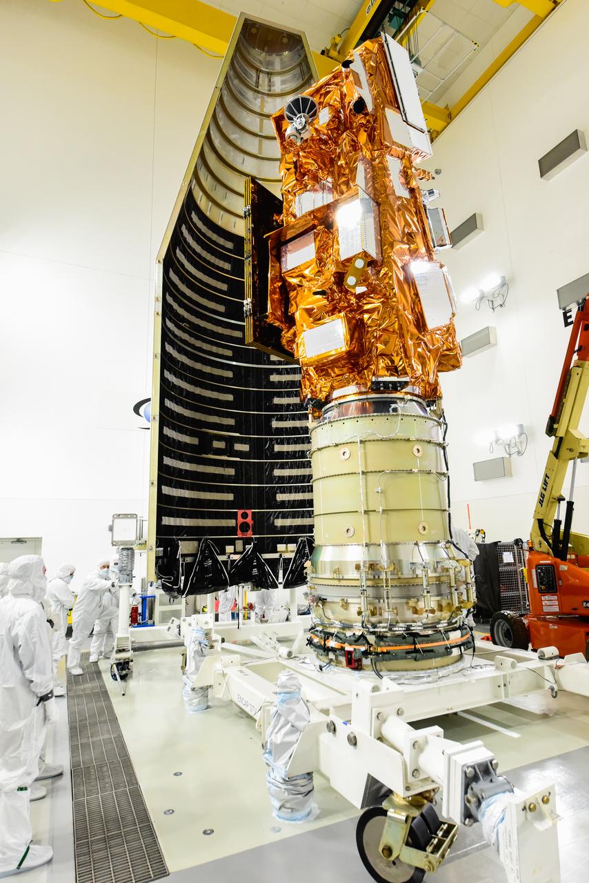
The National Oceanic and Atmospheric Administration’s (NOAA) Joint Polar Satellite System-2 (JPSS-2), stacked atop NASA’s Low-Earth Orbit Flight Test of an Inflatable Decelerator (LOFTID) secondary payload is being prepared for encapsulation in the United Launch Alliance Atlas V payload fairing inside the Astrotech Space Operations facility at Vandenberg Space Force Base (VSFB) in California on Oct. 12, 2022. JPSS-2 is the third satellite in the Joint Polar Satellite System series. It is scheduled to lift off from VSFB on Nov. 1 from Space Launch Complex-3. JPSS-2, which will be renamed NOAA-21 after reaching orbit, will join a constellation of JPSS satellites that orbit from the North to the South pole, circling Earth 14 times a day and providing a full view of the entire globe twice daily. The NOAA/NASA Suomi National Polar-orbiting Partnership (Suomi NPP) satellite, and NOAA-20, previously known as JPSS-1, are both already in orbit. Each satellite carries at least four advanced instruments to measure weather and climate conditions on Earth. LOFTID is dedicated to the memory of Bernard Kutter. LOFTID will demonstrate inflatable heat shield technology that could enable a variety of proposed NASA missions to destinations such as Mars, Venus, and Titan, as well as returning heavier payloads from low-Earth orbit.
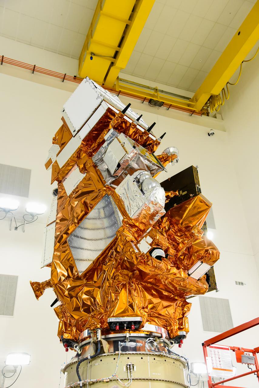
The National Oceanic and Atmospheric Administration’s (NOAA) Joint Polar Satellite System-2 (JPSS-2) is in view inside the Astrotech Space Operations facility at Vandenberg Space Force Base (VSFB) in California on Oct. 12, 2022. JPSS-2 is being prepared for encapsulation inside United Launch Alliance Atlas V payload fairing. The satellite is stacked atop NASA’s Low-Earth Orbit Flight Test of an Inflatable Decelerator (LOFTID) secondary payload. JPSS-2 is the third satellite in the Joint Polar Satellite System series. It is scheduled to lift off from VSFB on Nov. 1 from Space Launch Complex-3. JPSS-2, which will be renamed NOAA-21 after reaching orbit, will join a constellation of JPSS satellites that orbit from the North to the South pole, circling Earth 14 times a day and providing a full view of the entire globe twice daily. The NOAA/NASA Suomi National Polar-orbiting Partnership (Suomi NPP) satellite, and NOAA-20, previously known as JPSS-1, are both already in orbit. Each satellite carries at least four advanced instruments to measure weather and climate conditions on Earth. LOFTID is dedicated to the memory of Bernard Kutter. LOFTID will demonstrate inflatable heat shield technology that could enable a variety of proposed NASA missions to destinations such as Mars, Venus, and Titan, as well as returning heavier payloads from low-Earth orbit.
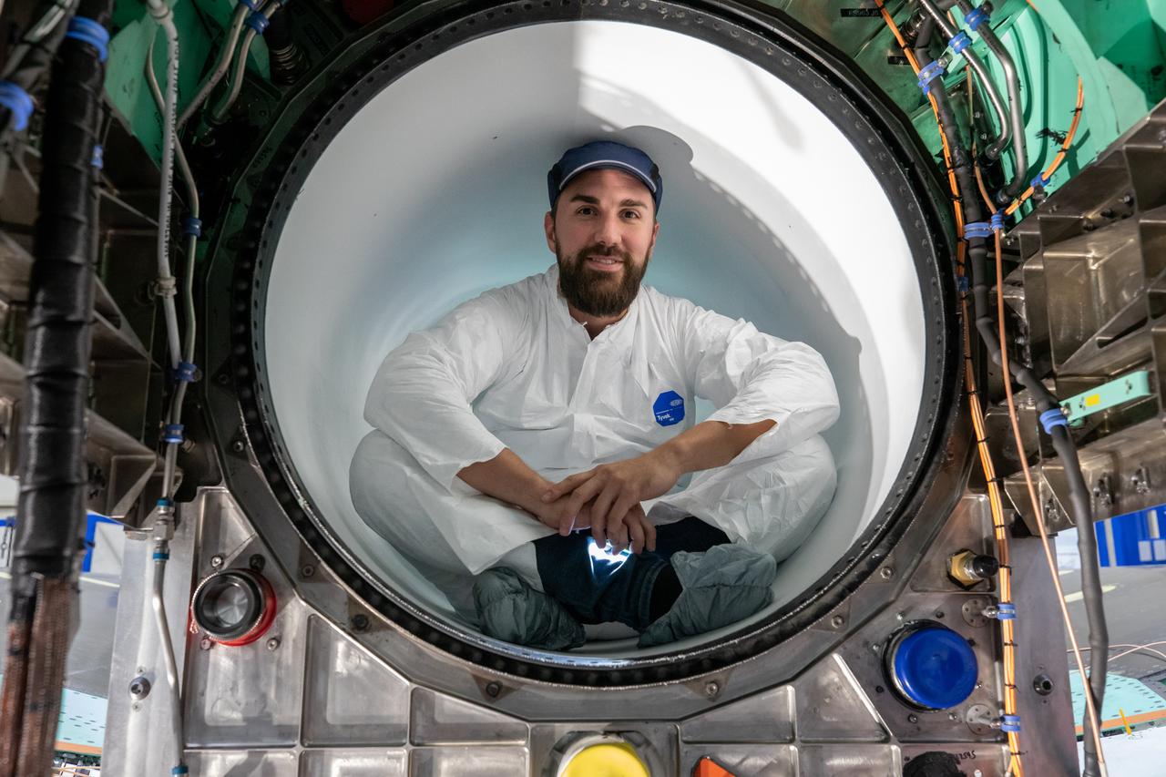
A Lockheed Martin Skunk Works technician takes a break for a photo. Note that the technician is wearing protective clean gear while sitting inside the X-59 engine inlet. Wearing this gear reduces the chance of any foreign objects from damaging the engine inlet.

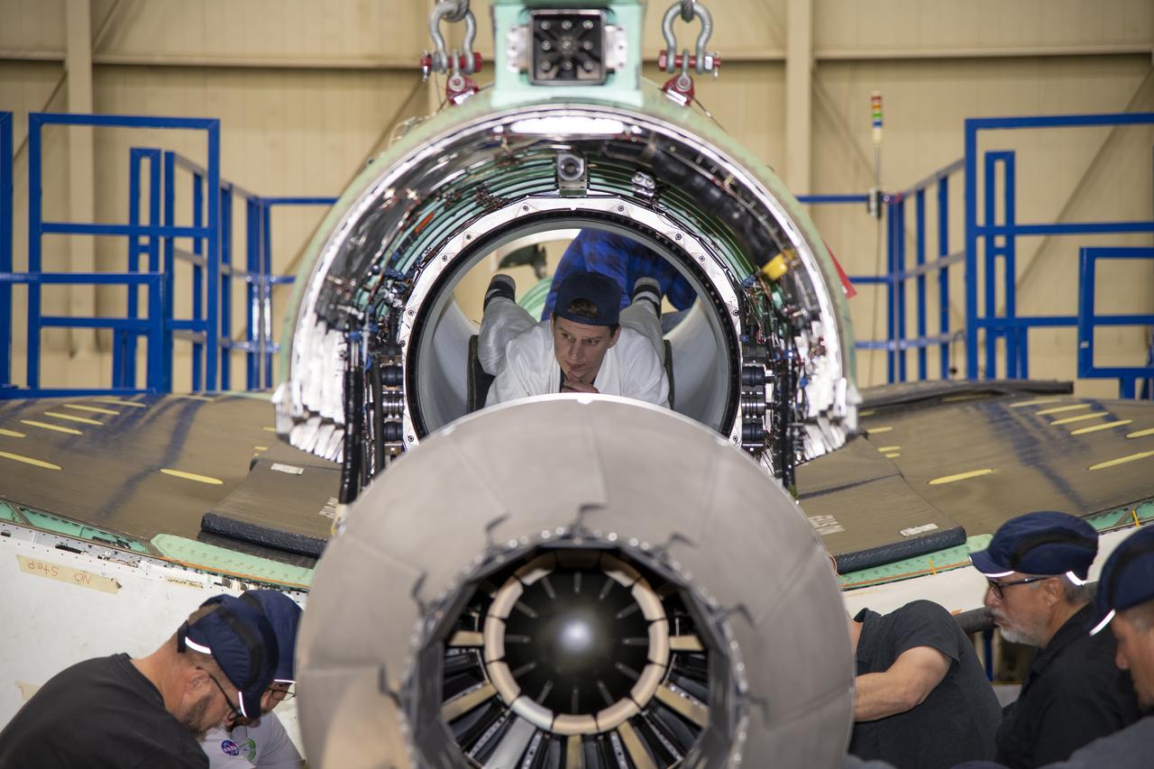
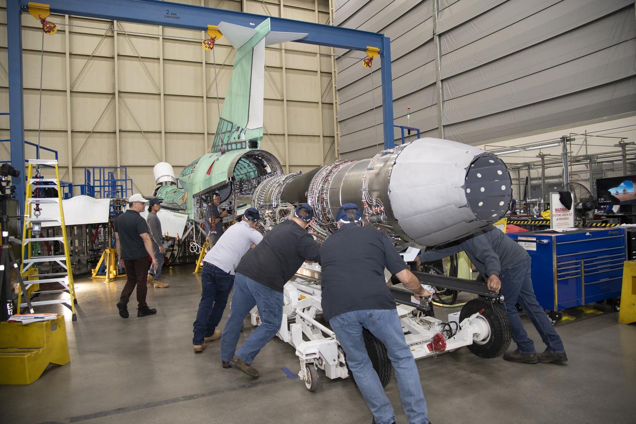
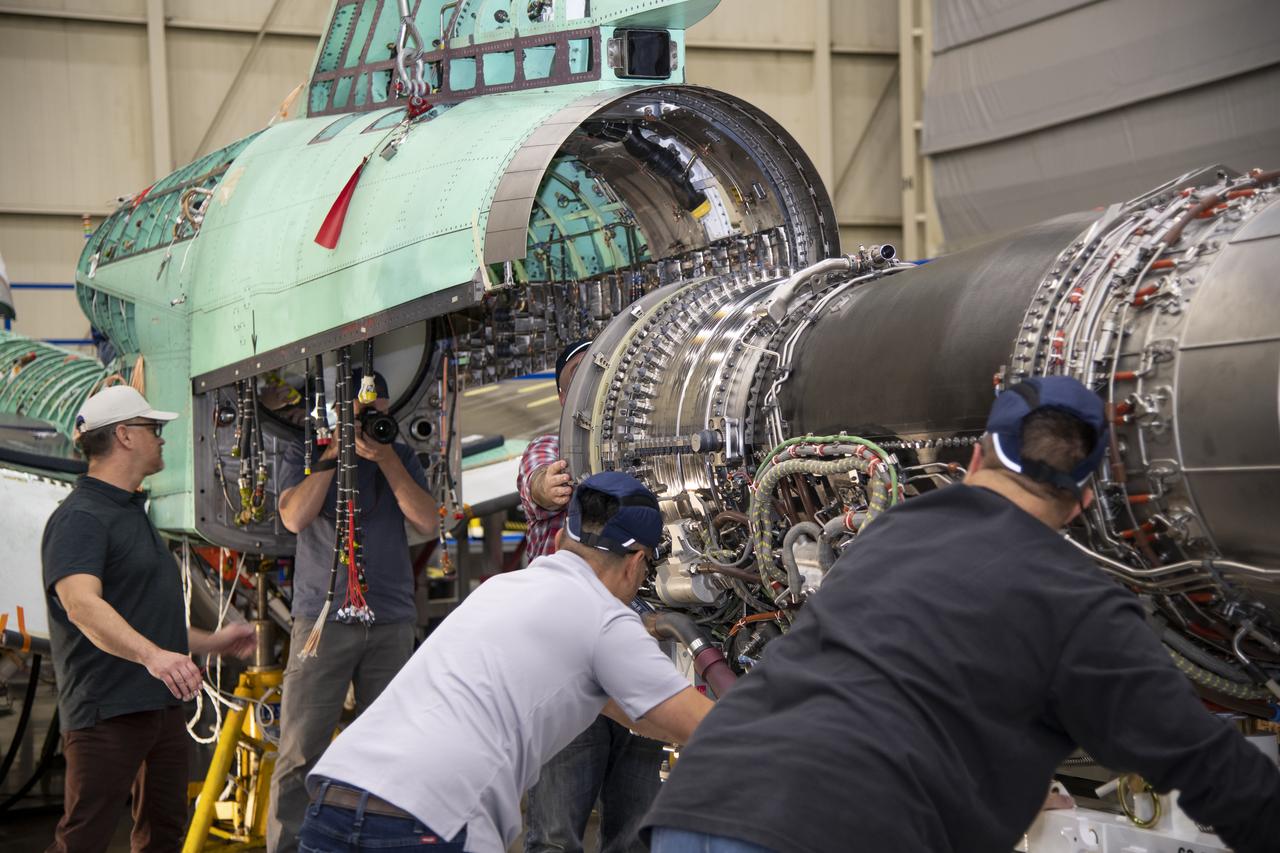
Here is an image of the X-59’s 13-foot General Electric F414 engine as the team prepares for a fit check. Making sure components, like the aircraft’s hydraulic lines, which help control functions like brakes or landing gear, and wiring of the engine, fit properly is essential to the aircraft’s safety. Once complete, the X-59 aircraft will demonstrate the ability to fly supersonic while reducing the loud sonic boom to a quiet sonic thump and help enable commercial supersonic air travel over land.
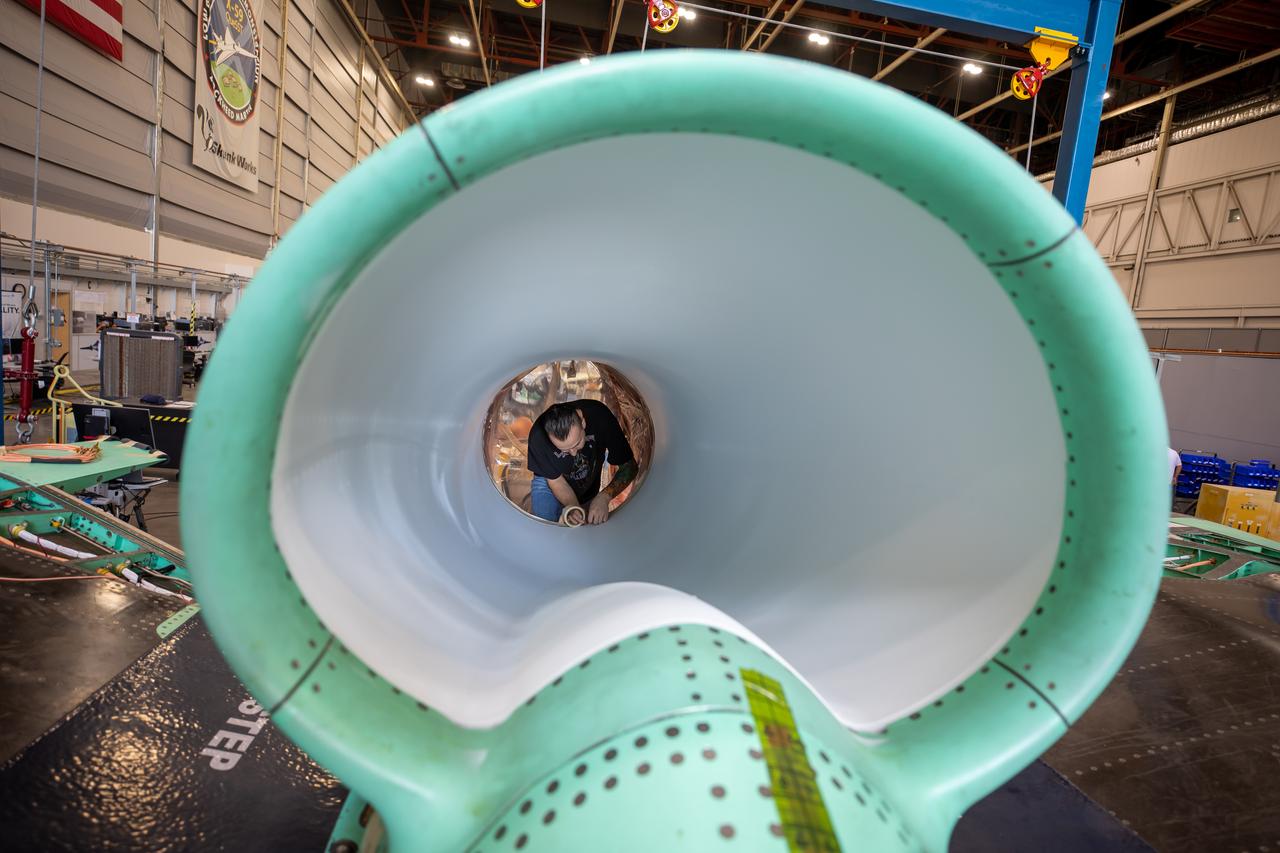
This is an image of the X-59 inlet with a safety covering. The inlet’s purpose is to adjust air speeds before they pass through the aircraft’s engine. The purpose of the covering is to protect the inlet and engine from foreign objects.
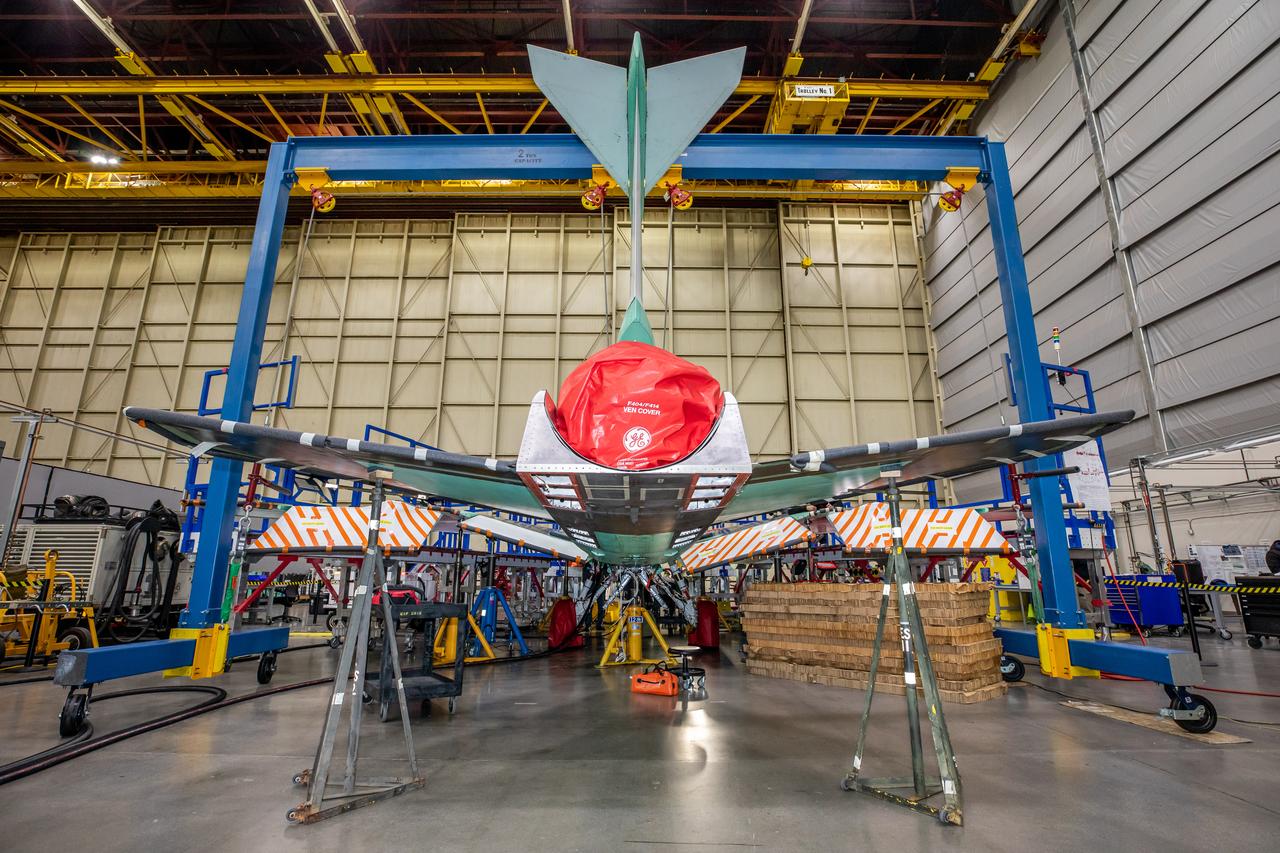
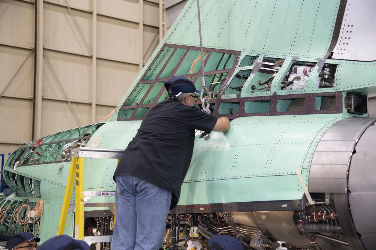
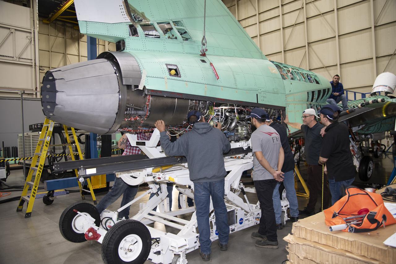
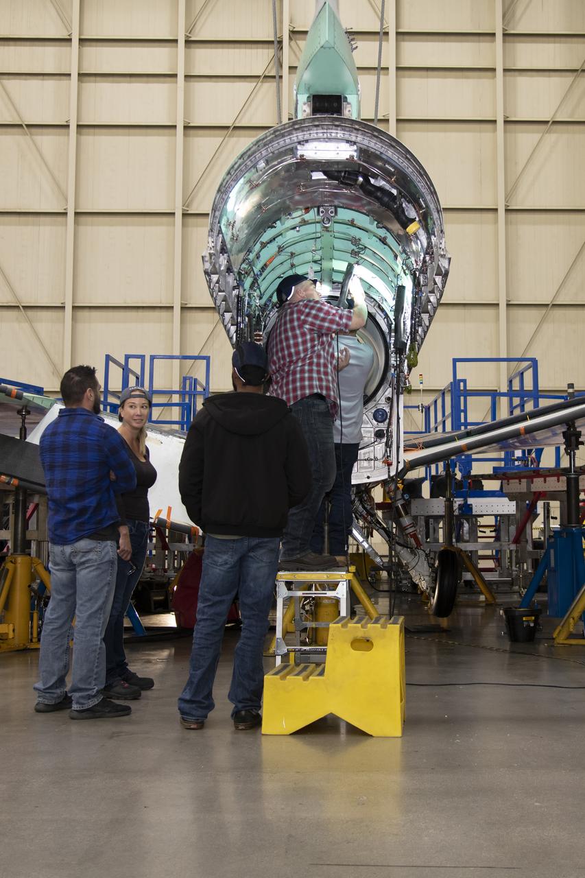
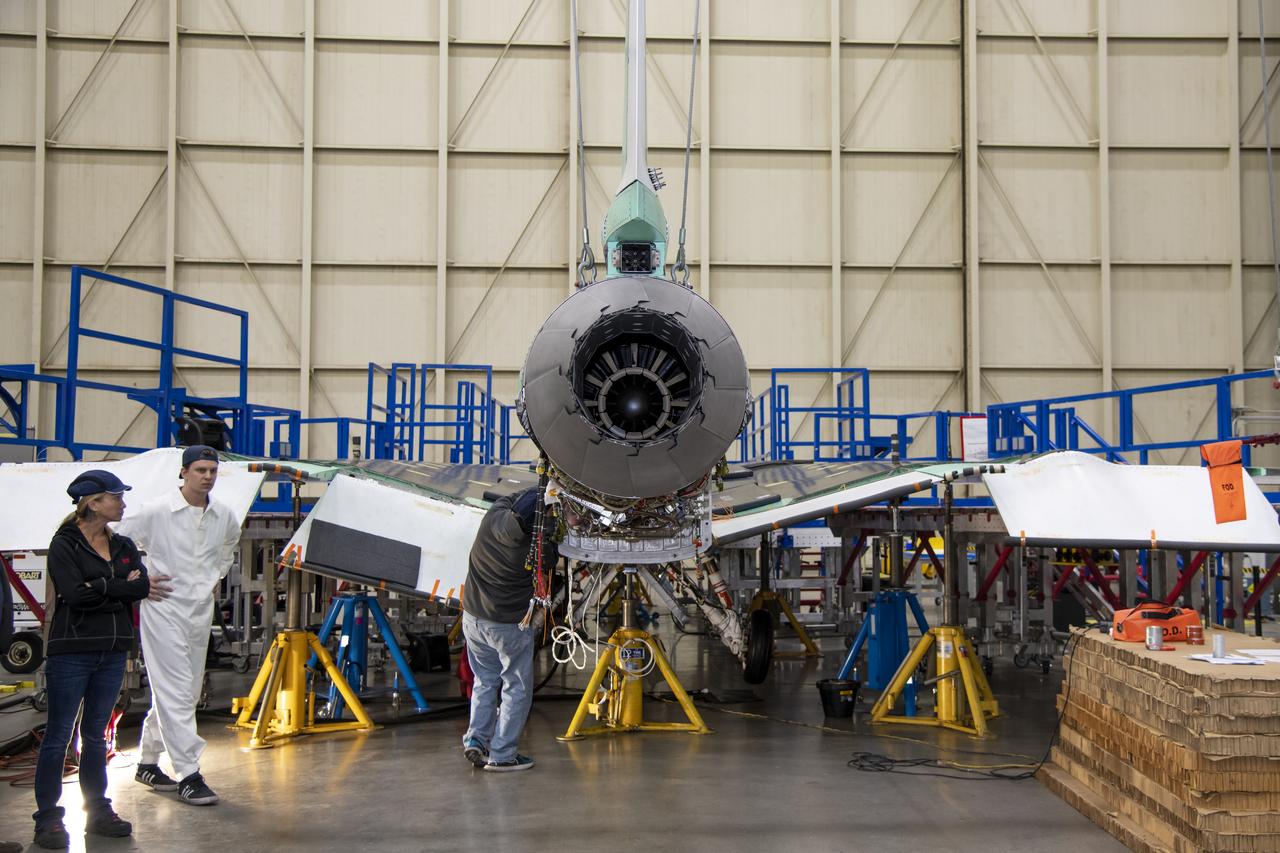
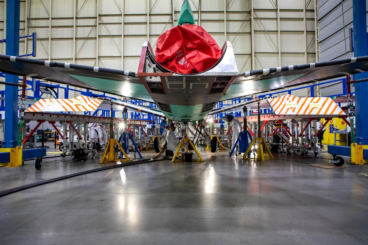
NASA’s X-59 sits in support framing while undergoing the installation of its lower empennage, or tail section, at Lockheed Martin Skunk Works in Palmdale, California in late March.
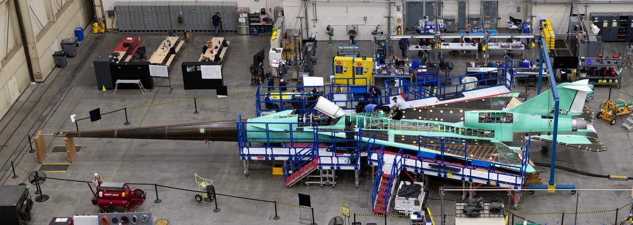
An overhead view of the X-59 during assembly in spring 2023. Assembly took place at Lockheed Martin’s Skunk Works facility in Palmdale, California. Once complete, the X-59 is designed to fly supersonic while reducing the loud sonic boom. The Quesst mission could help change the rules for commercial supersonic air travel over land.
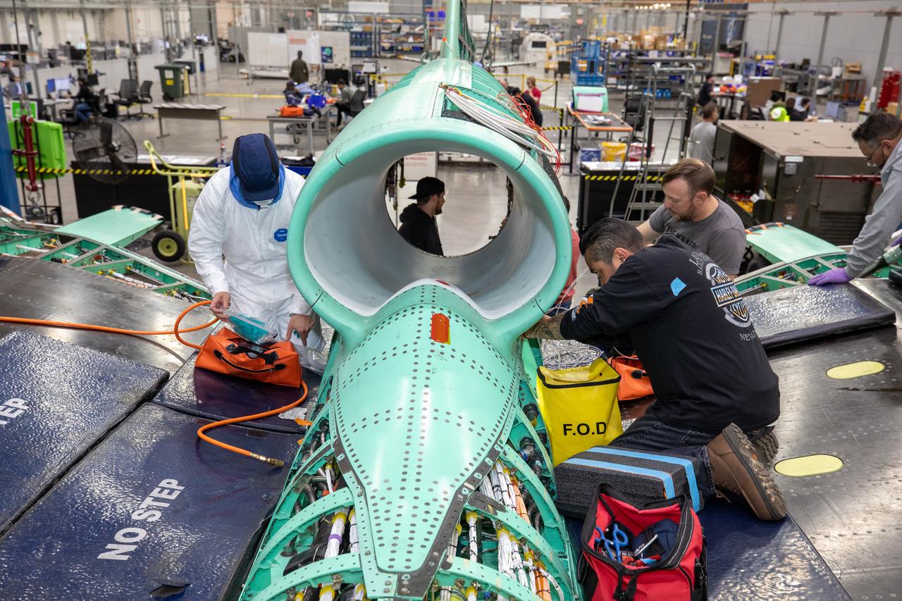
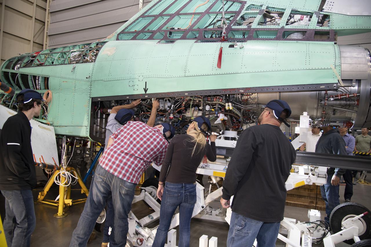
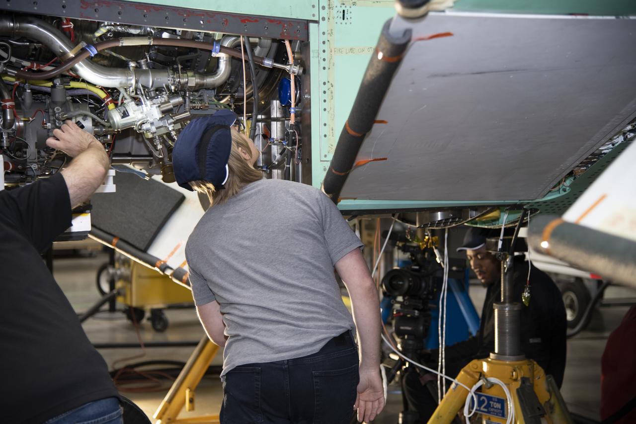
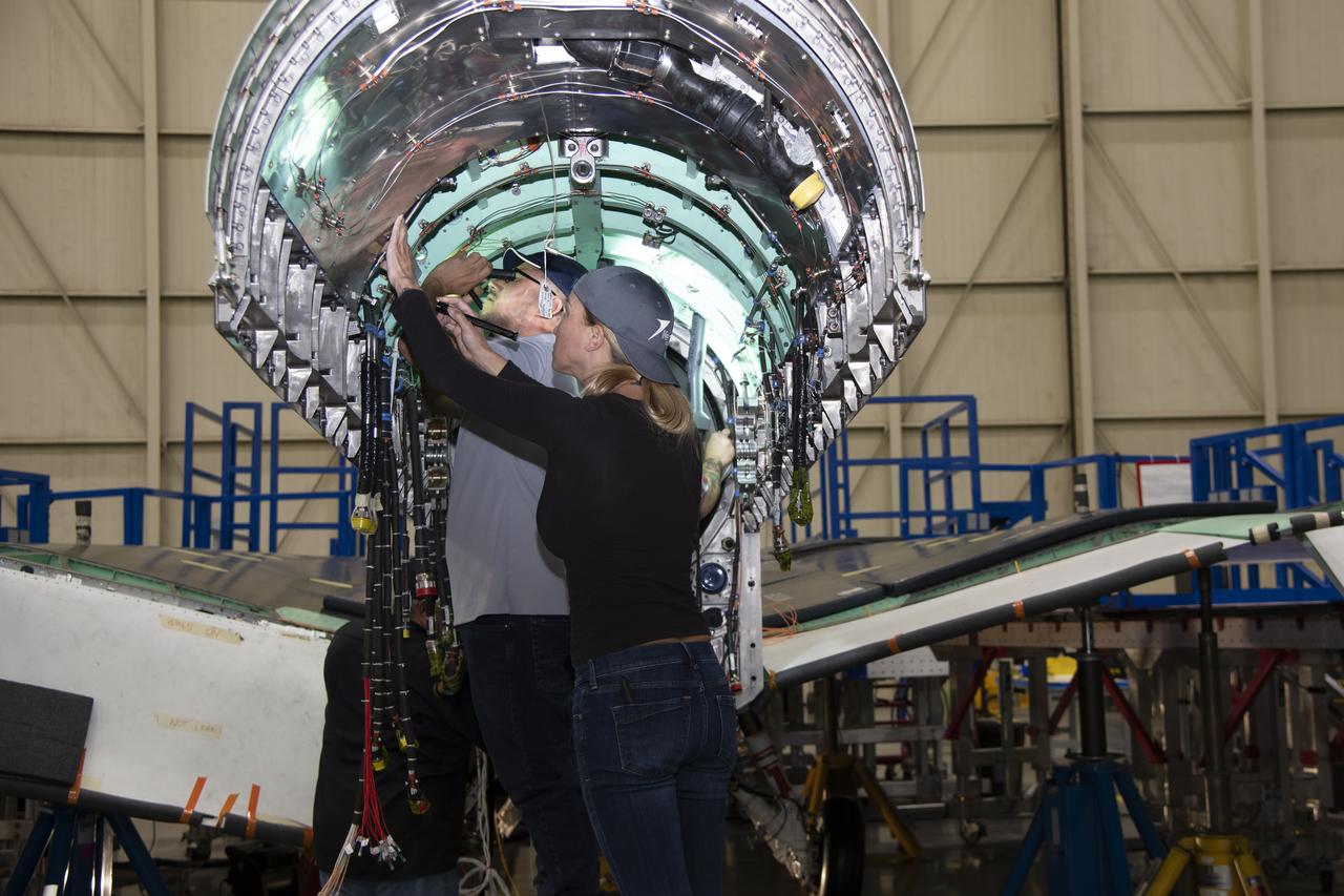
The X-59 team working on the aircraft’s wiring around the engine inlet prior to the engine being installed. Once complete, the X-59 is designed to fly supersonic while reducing the loud sonic boom. The Quesst mission could help change the rules for commercial supersonic air travel over land.
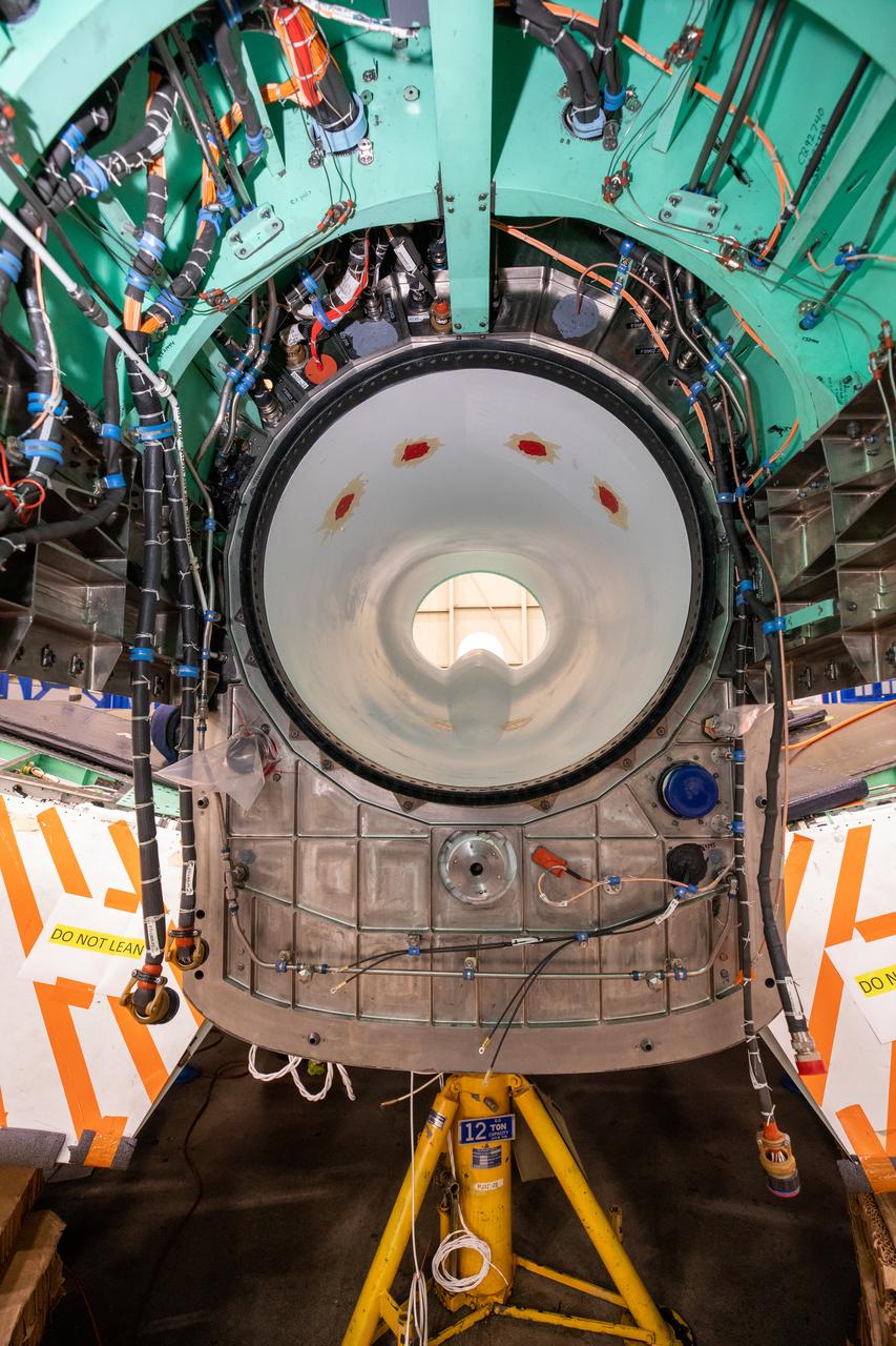
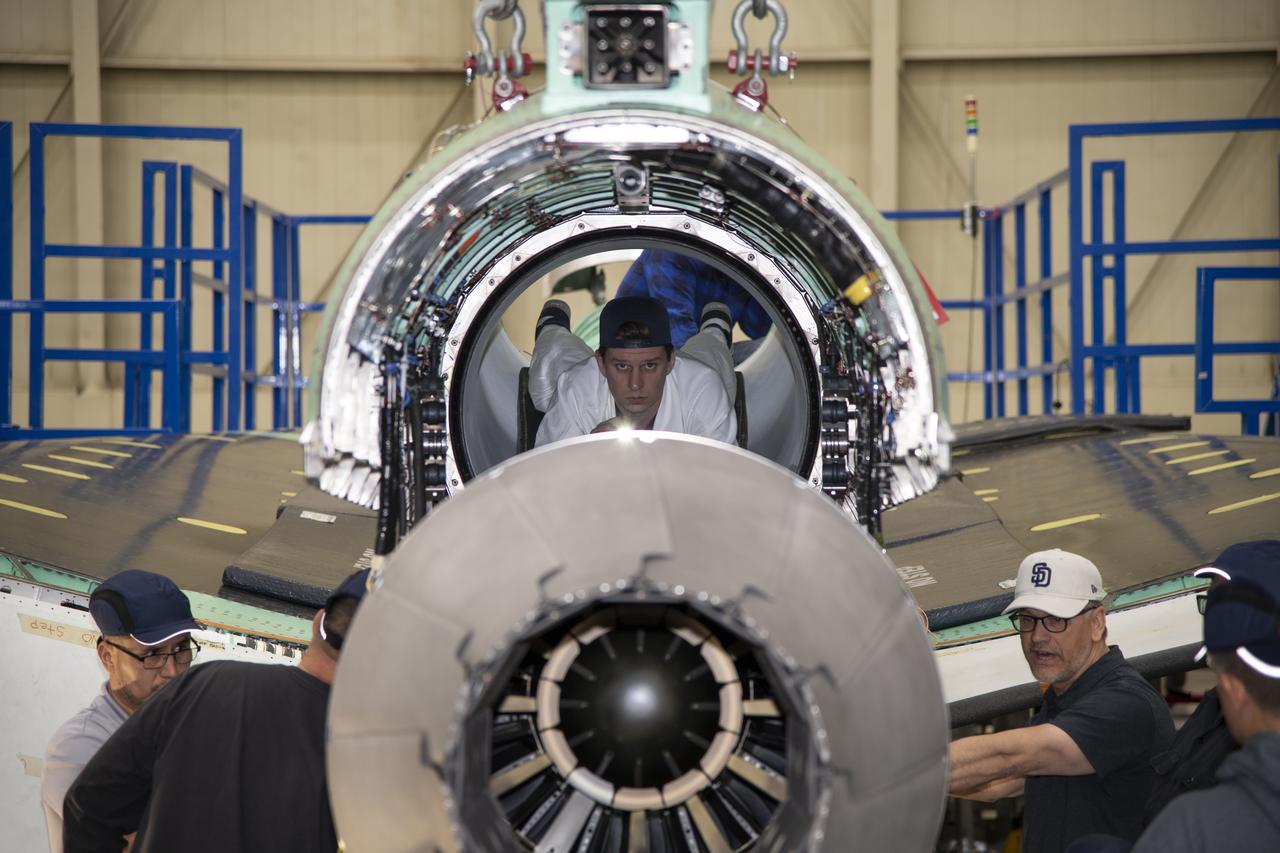
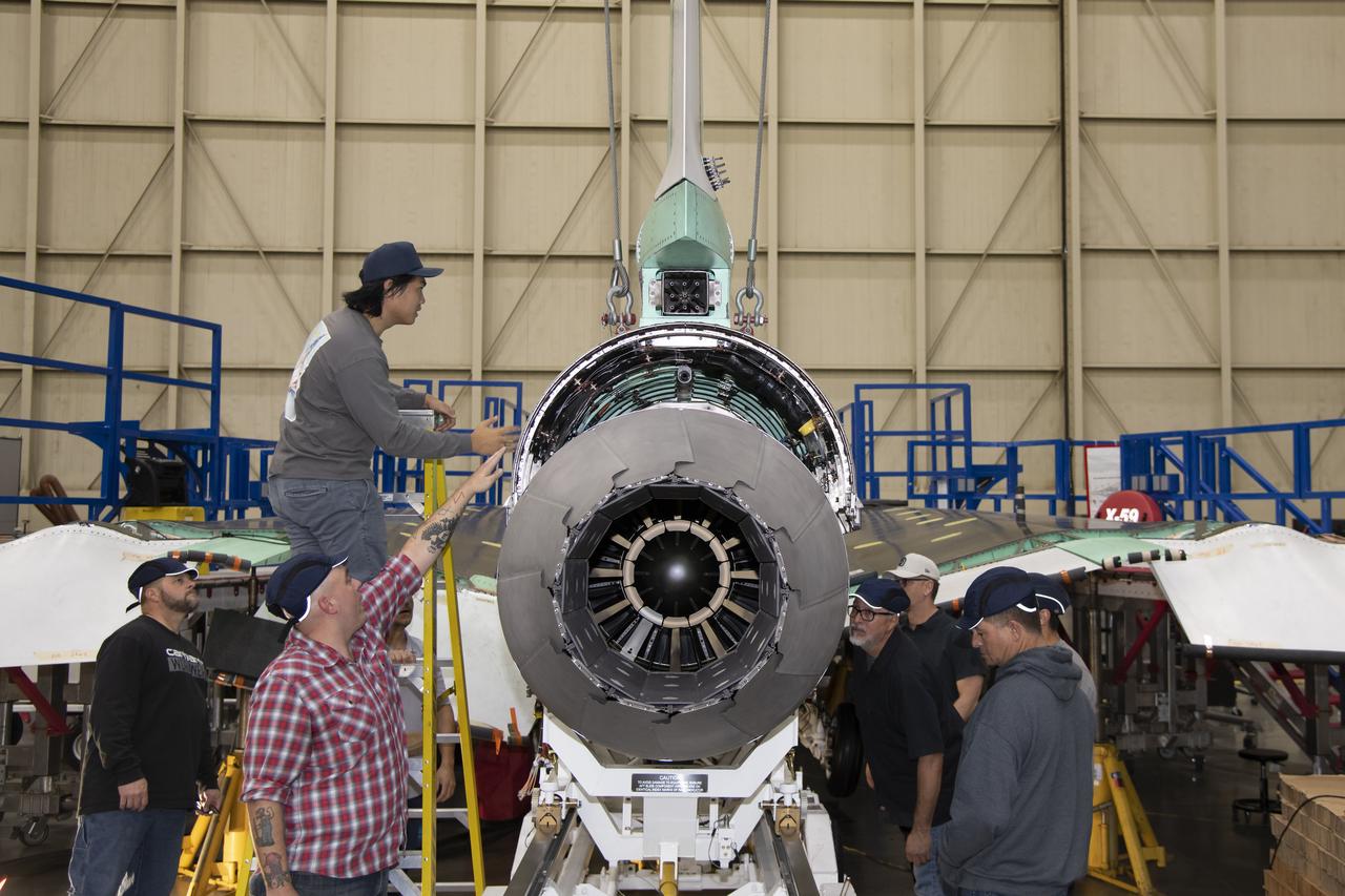
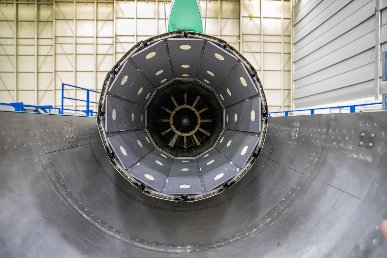
This image shows the X-59’s engine inlet from the aft view, which is the rear of the airplane, looking forward. Once the aircraft and ground testing are complete, the X-59 will undergo flight testing, which will demonstrate the plane’s ability to fly supersonic - faster than the speed of sound - while reducing the loud sonic boom. This could enable commercial supersonic air travel over land again.
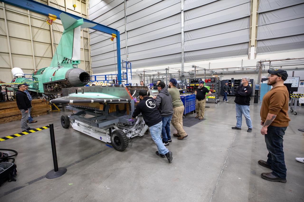
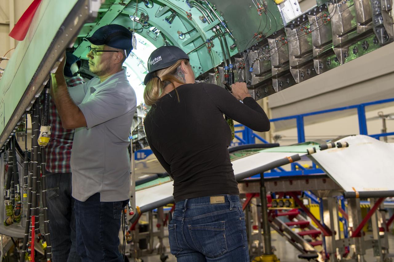
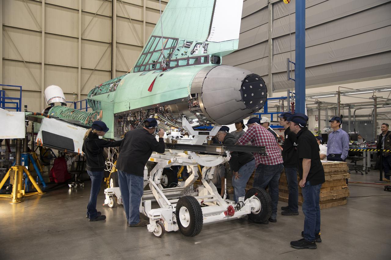
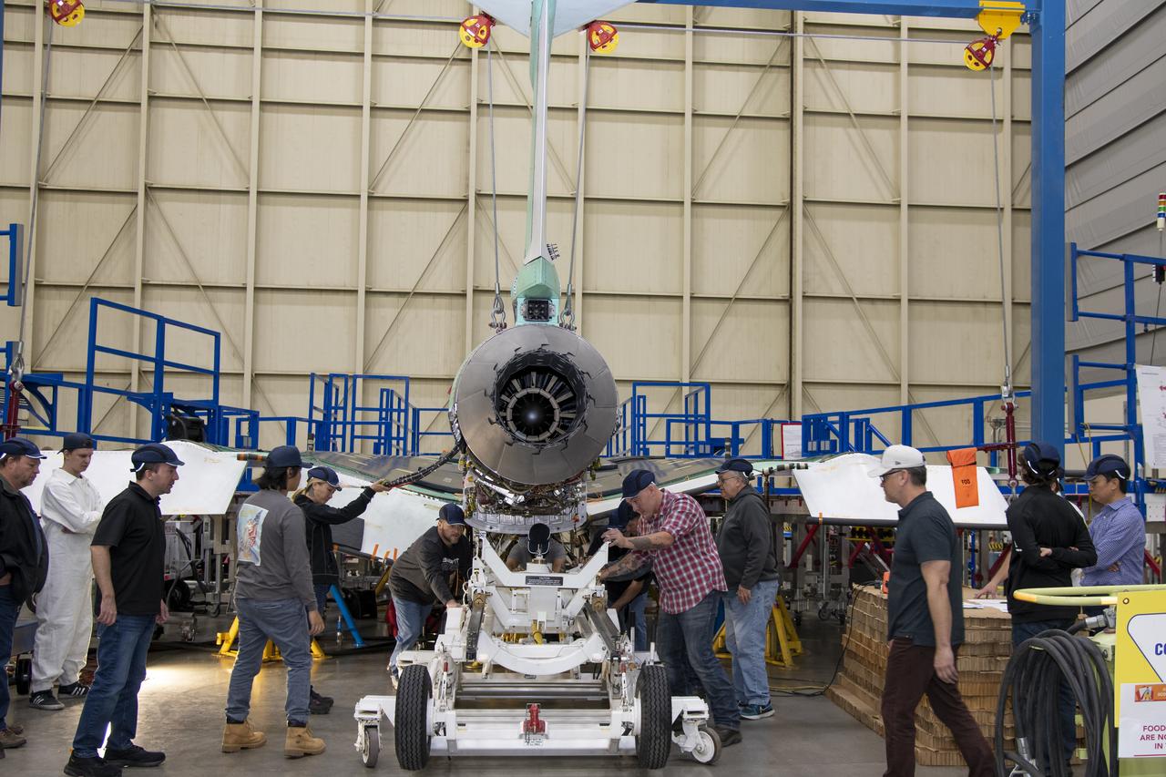
The X-59 team at Lockheed Martin Skunk Works in Palmdale, California, load the lower empennage - the tail section - into place. The surfaces used to control the tilt of the airplane are called stabilators and are connected to the lower empennage. The X-59 is the centerpiece of NASA’s Quesst mission, which could help enable commercial supersonic air travel over land.
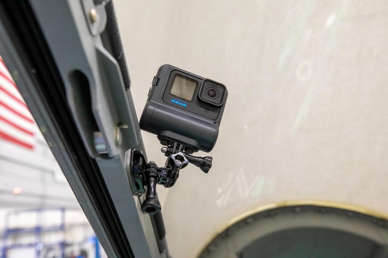
A Go-Pro is mounted on the inside of the X-59’s cockpit to capture the pilots activities during flight.
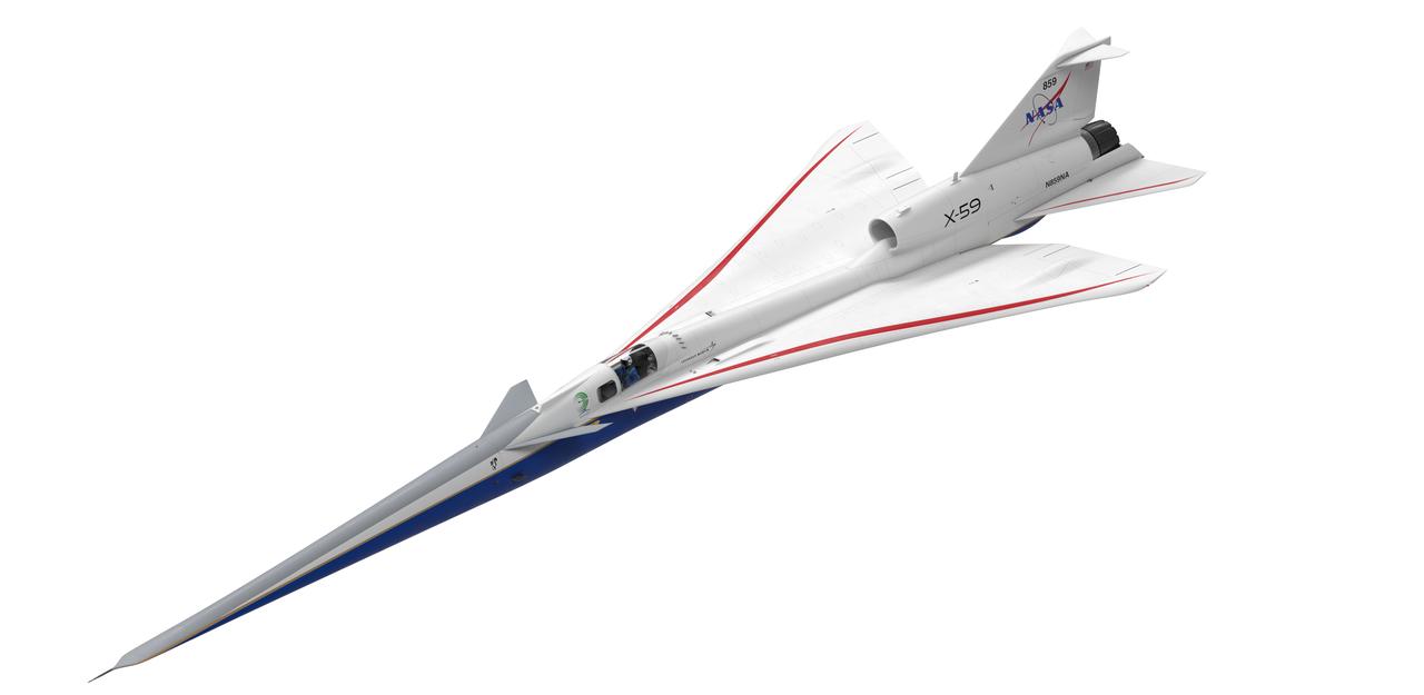
Artist concept of the X-59 three forths view top
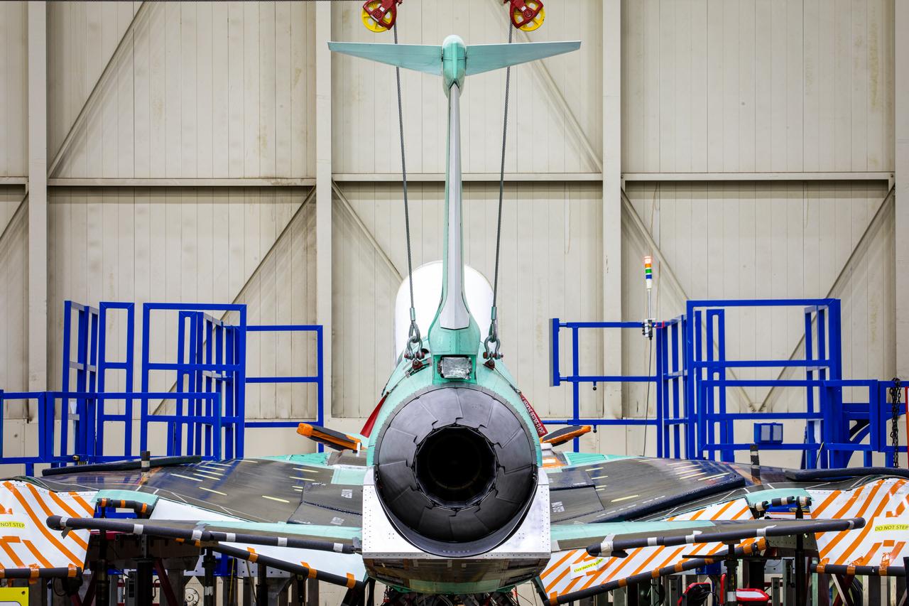
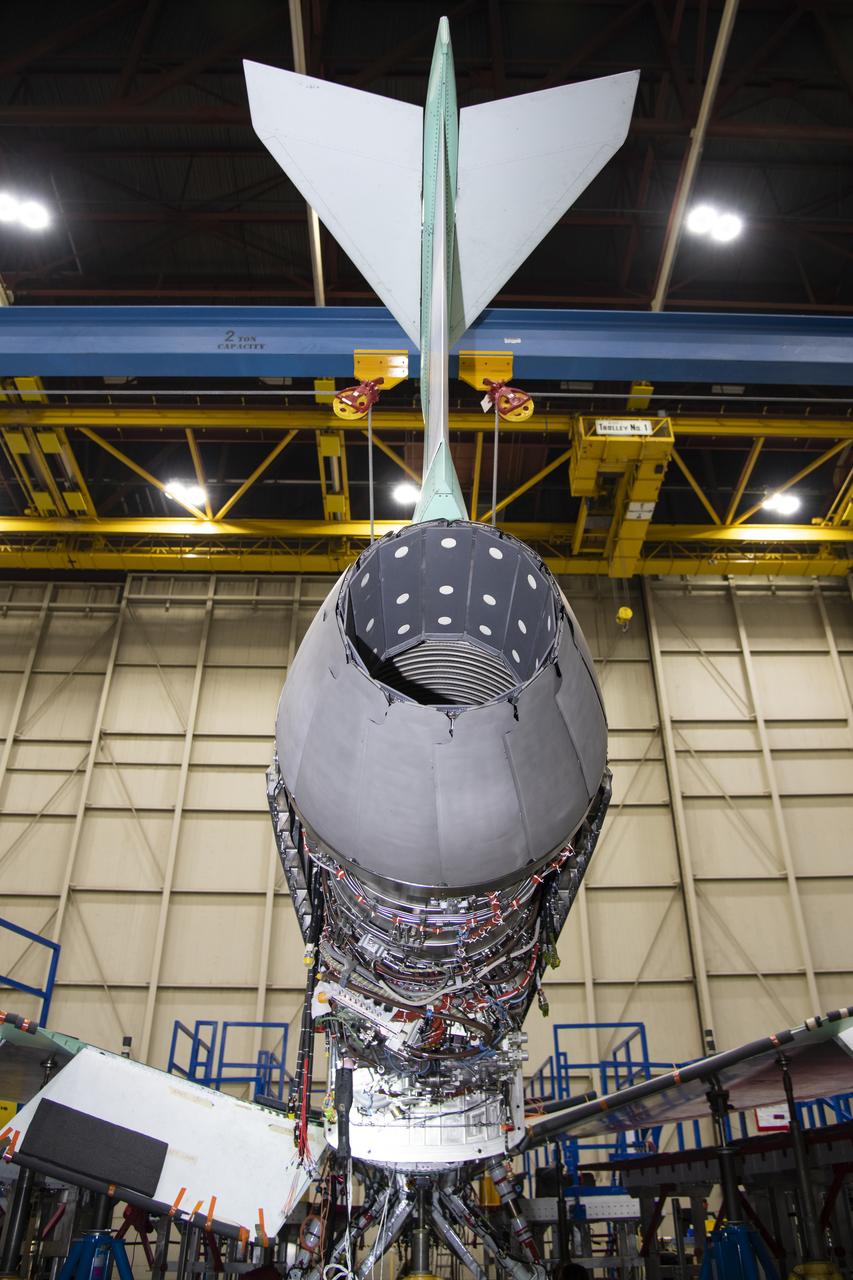
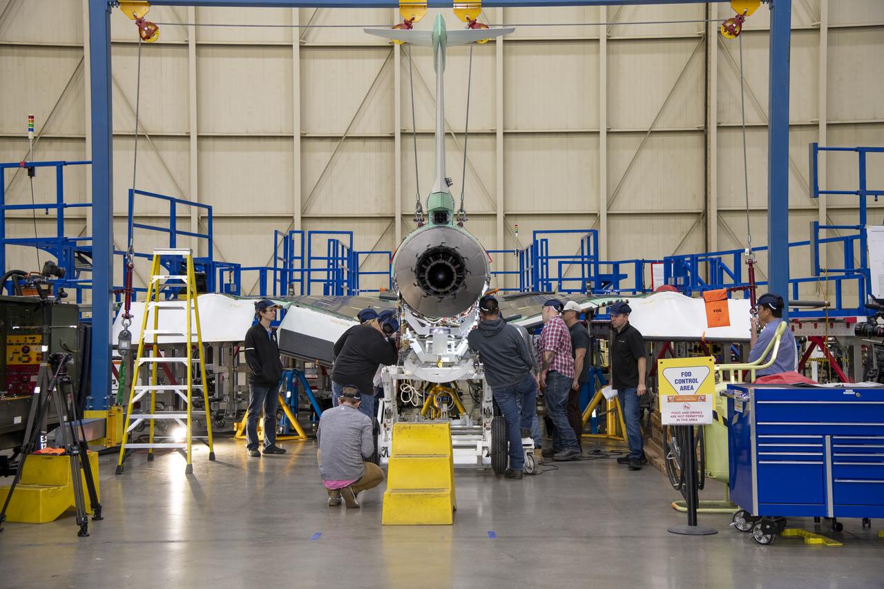
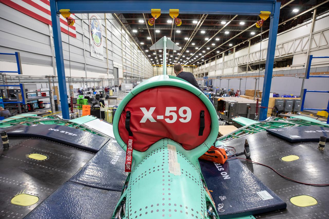
A perfectly framed up rearview shot of NASA’s X-59 tail after its recent installation of the lower empennage, or tail section, in late March at Lockheed Martin Skunk Works in Palmdale, California.
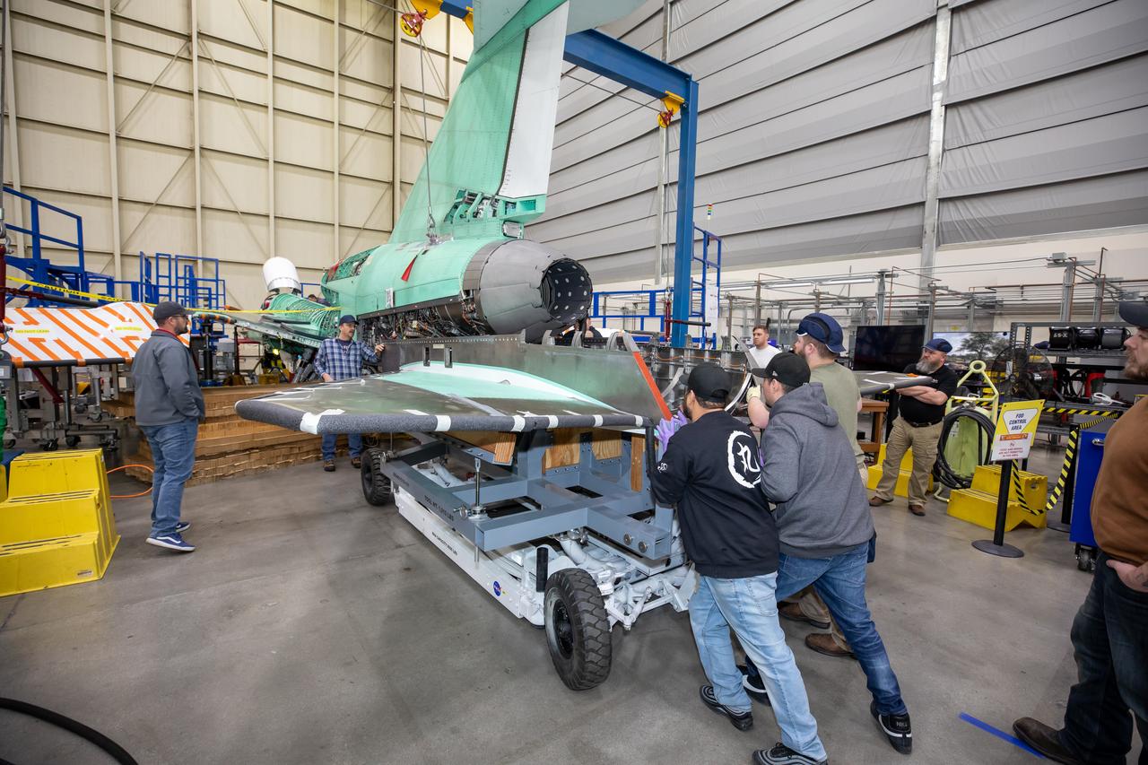
The X-59 team at Lockheed Martin Skunk Works in Palmdale, California, load the lower empennage - the tail section - into place. The surfaces used to control the tilt of the airplane are called stabilators and are connected to the lower empennage. The X-59 is the centerpiece of NASA’s Quesst mission, which could help enable commercial supersonic air travel over land.
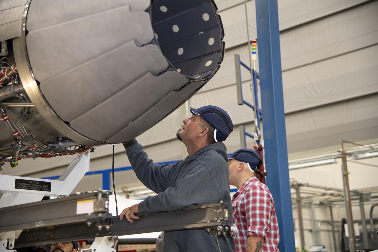
A look at the X-59’s engine nozzle, where the thrust -the force that moves the aircraft- will exit. Once complete, the X-59 is designed to fly supersonic while reducing the loud sonic boom. The Quesst mission could help change the rules for commercial supersonic air travel over land.
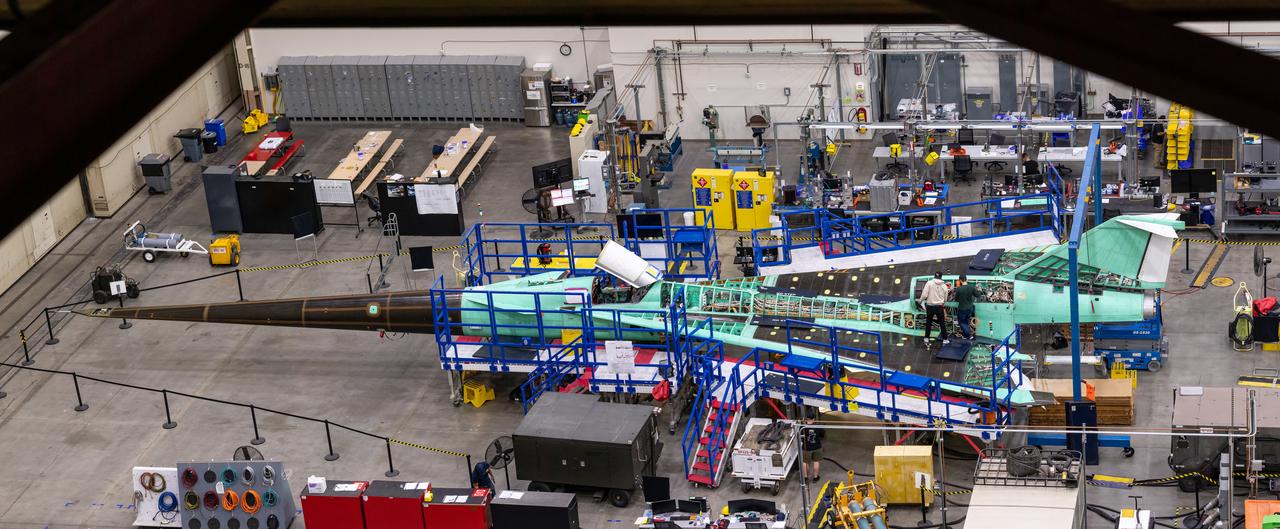
This is an overhead view of the X-59 aircraft at Lockheed Martin Skunk Works in Palmdale, California. The nose was installed, and the plane awaits engine installation. Technicians continue to wire the aircraft as the team preforms several system checkouts to ensure the safety of the aircraft. The X-59 aircraft will demonstrate the ability to fly supersonic while reducing the loud sonic boom to a quiet sonic thump and help enable commercial supersonic air travel over land.

NASA test pilot, Nils Larson, inspects the X-59 cockpit displays and lighting system during system checkouts. The External Vision System (XVS) is displayed on the top screen, and the avionics flight displays, which can show navigation information or aircraft status, are shown on the bottom two screens.
Technicians perform landing gear checkout testing at Lockheed Martin Skunk Works in Palmdale, California. These tests make sure that all the parts of X-59’s landing gear and doors are working in the correct order. The X-59 is the centerpiece of NASA’s Quesst mission, which could help enable commercial supersonic air travel over land.
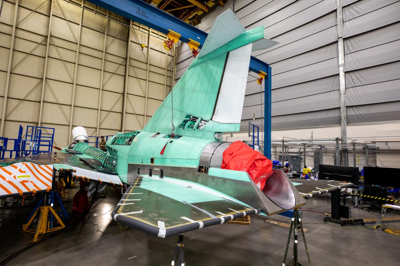
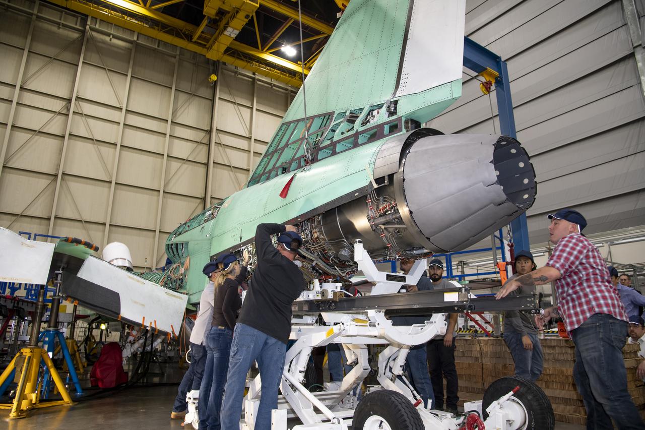
The tail of NASA’s X-59 aircraft is shown here in late March at Lockheed Martin Skunk Works in Palmdale, California where the plane recently underwent a final install of the lower empennage or better known as tail section of the plane.