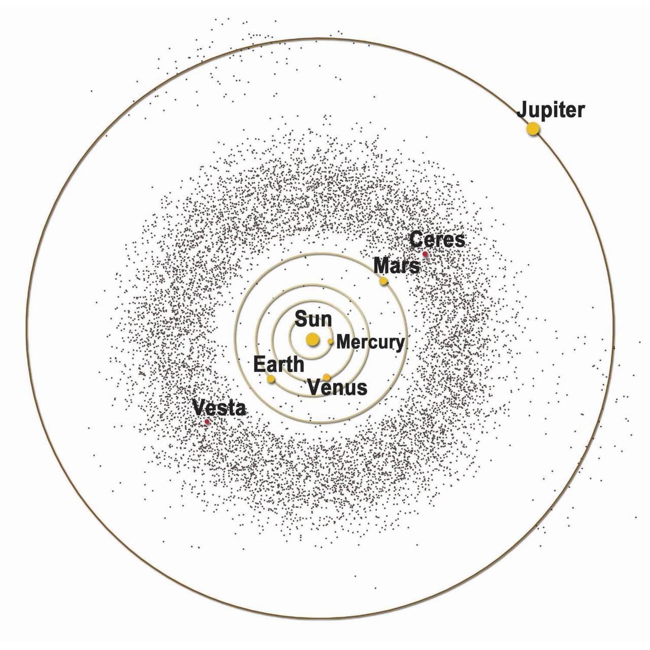
Artist graphic of the asteroid belt, part of Dawn Mission Art series. http://photojournal.jpl.nasa.gov/catalog/PIA19380

S69-59547 (20 Nov. 1969) --- The seismometer reading from the impact made by the Lunar Module ascent stage when it struck the lunar surface. The impact was registered by the Passive Seismic Experiment Package which was deployed on the moon by the Apollo 12 astronauts. PSEP, which is a component of the Apollo Lunar Surface Experiments Package, will detect surface tilt produced by tidal deformations, moonquakes, and meteorite impacts. The LM's ascent stage was jettisoned and sent journeying toward impact on the moon after astronauts Charles Conrad Jr. and Alan L. Bean returned to lunar orbit and rejoined astronaut Richard F. Gordon Jr. in the Command and Service Modules. Information from the PSEP is transmitted to Earth through the ALSEP's central station and monitored by equipment at the Manned Spacecraft Center.
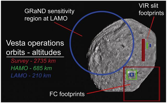
This graphic from NASA's Dawn shows fields of view of Dawn instruments from Survey orbit (red), High Altitude Mapping Orbit (green), and Low Altitude Mapping Orbit (blue) and is part of the Mission Art series from NASA's Dawn mission. http://photojournal.jpl.nasa.gov/catalog/PIA19371
STS050-S-001 (January 1992) --- Designed by the flight crew, the insignia for the United States Microgravity Laboratory (USML-1), captures a space shuttle traveling above Earth while trailing the USML banner. The orbiter is oriented vertically in a typical attitude for microgravity science and in this position represents the numeral 1 in the mission's abbreviated title. This flight represents the first in a series of USML flights on which the primary objective is microgravity science, planned and executed through the combined efforts of the United States of America's government, industry and academia. Visible in the payload bay are the Spacelab module, and the extended duration orbiter "cryo" pallet which will be making its first flight. The small g and Greek letter mu on the Spacelab module symbolize the microgravity environment being used for research in the areas of materials science and fluid physics. The large block letter U extends outside the patch perimeter, symbolizing the potential for the experiments on this flight to expand the current boundaries of knowledge in microgravity science. The Stars and Stripes of the USML block letters and the United States landmass in the Earth scene below reflect the crew's pride in the United States origin of all onboard experiments. The NASA insignia design for space shuttle flights is reserved for use by the astronauts and for other official use as the NASA Administrator may authorize. Public availability has been approved only in the forms of illustrations by the various news media. When and if there is any change in this policy, which is not anticipated, the change will be publicly announced. Photo credit: NASA
STS058-S-001 (May 1993) --- Designed by members of the flight crew, the STS-58 insignia depicts the space shuttle Columbia with a Spacelab module in its payload bay in orbit around Earth. The Spacelab and the lettering "Spacelab Life Sciences II" highlight the primary mission of the second space shuttle flight dedicated to life sciences research. An Extended Duration Orbiter (EDO) support pallet is shown in the aft payload bay, stressing the scheduled two-week duration of the longest space shuttle mission to date. The hexagonal shape of the patch depicts the carbon ring, a molecule common to all living organisms. Encircling the inner border of the patch is the double helix of DNA, representing the genetic basis of life. Its yellow background represents the sun, energy source for all life on Earth. Both medical and veterinary caducei are shown to represent the STS-58 life sciences experiments. The position of the spacecraft in orbit about Earth with the United States in the background symbolizes the ongoing support of the American people for scientific research intended to benefit all mankind. The NASA insignia design for space shuttle flights is reserved for use by the astronauts and for other official use as the NASA Administrator may authorize. Public availability has been approved only in the form of illustrations by the various news media. When and if there is any change in this policy, which we do not anticipate, it will be publicly announced. Photo credit: NASA
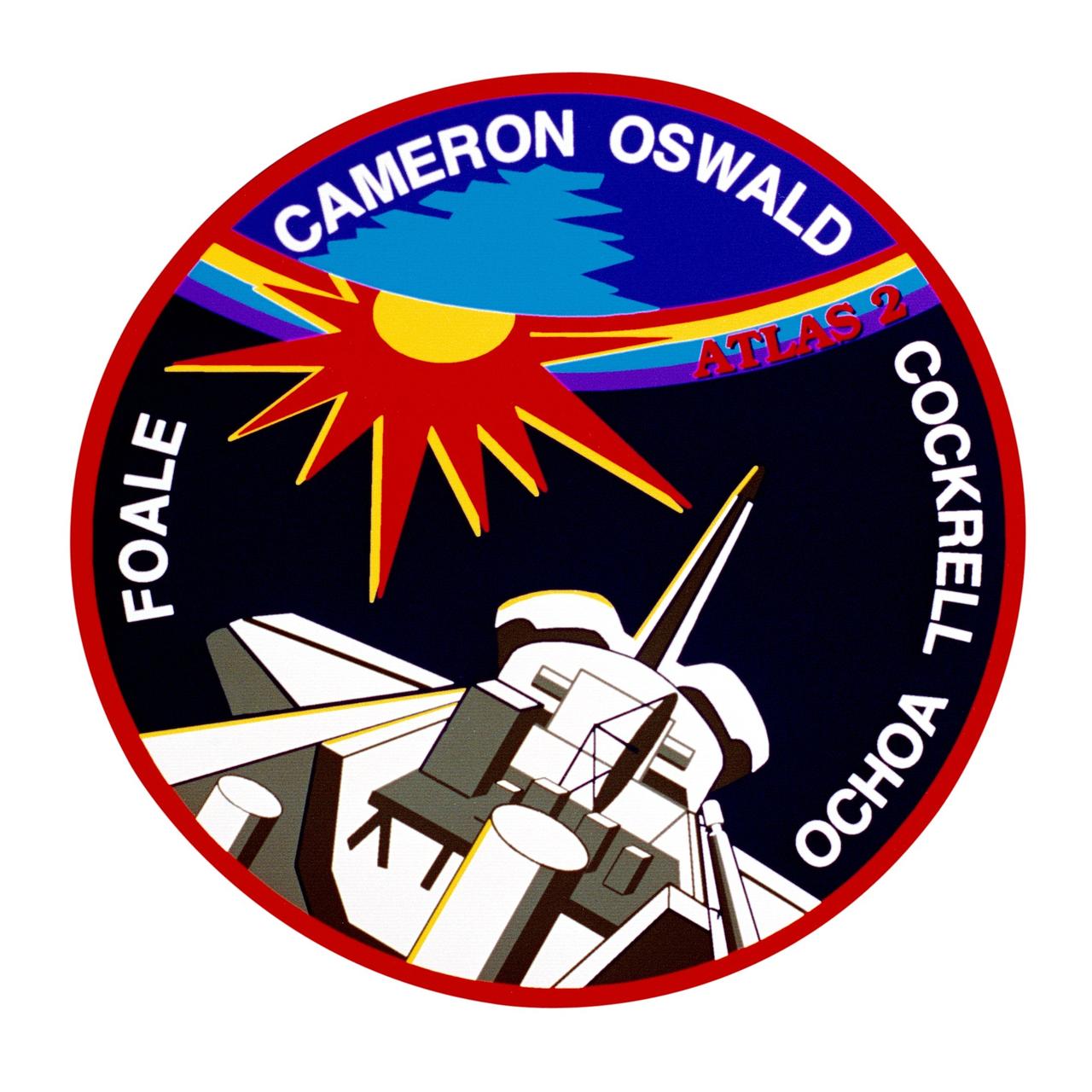
STS056-S-001 (January 1993) --- The patch is a pictorial representation of the STS-56/ATLAS-2 mission as seen from the crew's viewpoint. The payload bay is depicted with the ATLAS-2 pallet, Shuttle Solar Backscatter Ultra Violet (SSBUV) experiment, and Spartan -- the two primary scientific payloads on the flight. With ATLAS-2 serving as part of the "Mission to Planet Earth" (MTPE) project, the crew has depicted the planet prominently in the artwork. Two primary areas of study are the atmosphere and the sun. To highlight this, Earth's atmosphere is depicted as a stylized visible spectrum and the sunrise is represented with an enlarged two-colored corona. Surnames of the commander and pilot are inscribed in the Earth field, with the surnames of the mission specialists appearing in the space background. The NASA insignia design for space shuttle flights is reserved for use by the astronauts and for other official use as the NASA Administrator may authorize. Public availability has been approved only in the form of illustrations by the various news media. When and if there is any change in this policy, which we do not anticipate, it will be publicly announced. Photo credit: NASA

S73-23952 (May 1973) --- This is the official emblem for the National Aeronautics and Space Administration's (NASA) Skylab Program. The emblem depicts the United States Skylab space station cluster in Earth orbit with the sun in the background. Skylab will evaluate systems and techniques designed to gather information on Earth resources and environmental problems. Solar telescopes will increase man's knowledge of our sun and the multitude of solar influences on Earth environment. Medical experiments will increase knowledge of man himself and his relationship to his earthly environment and adaptability to spaceflight. Additionally, Skylab will experiment with industrial processes which may be enhanced by the unique weightless, vacuum environment of orbital spaceflight. The 100-ton laboratory complex Skylab space station is composed of the Command/Service Module (CSM), Orbital Workshop (OW), Apollo Telescope Mount (ATM), Multiple Docking Adapter (MDA), and Airlock Module (AM). The NASA insignia design for Skylab is reserved for use by the astronauts and for other official use as the NASA Administrator may authorize. Public availability has been approved only in the form of illustrations by the various news media. When and if there is any change in this policy, which we do not anticipate, it will be publicly announced. Photo credit: NASA

STS054-S-001 (July 1992) --- Designed by the crew members, the STS-54 crew patch depicts our national symbol, the American bald eagle, soaring above the Earth; and represents the United States Space Shuttle as a national asset in service to America and the world. The eagle is clutching an eight pointed star in its talons and is placing this larger star among a constellation of four others representing the placement of the fifth Tracking and Data Relay Satellite (TDRS) into orbit among the four already in service. The blackness of space with stars conspicuously absent represents the mission?s other primary objective in carrying the Diffuse X-ray Spectrometer into orbit to conduct astronomical observations of x-ray sources within the galaxy and throughout the universe. The depiction of our planet showing the crew?s home continent of North America is an expression of their and NASA?s intention that the medical and scientific experiments conducted onboard are for the benefit of all mankind. The clouds and blue of the Earth represent the crew?s part in NASA?s Mission to Planet Earth in conducting Earth observation photography. The NASA insignia design for space shuttle flights is reserved for use by the astronauts and for other official use as the NASA Administrator may authorize. Public availability has been approved only in the form of illustrations by the various news media. When and if there is any change in this policy, which we do not anticipate, it will be publicly announced. Photo credit: NASA
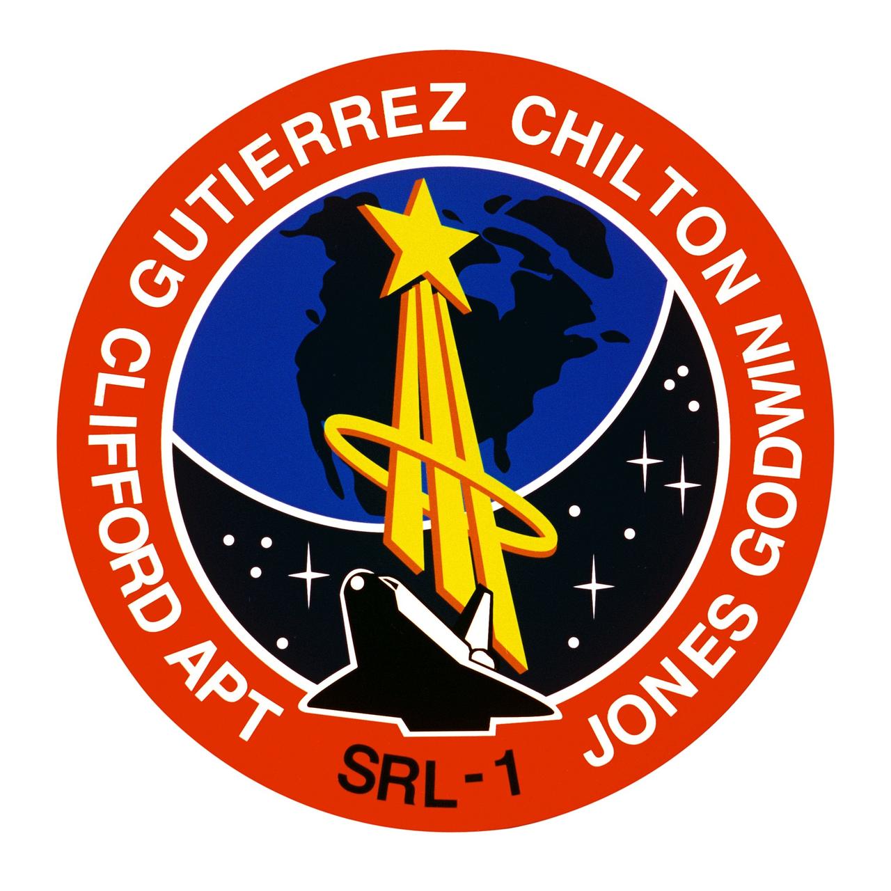
STS059-S-001 (November 1993) --- Designed by the crew members, the STS-59 insignia is dominated by Earth, reflecting the focus of the first Space Radar Laboratory (SRL-1) mission upon our planet's surface and atmosphere. The golden symbol of the astronaut corps emblem sweeps over Earth's surface from the space shuttle Endeavour, representing the operation of the SIR-C/Synthetic Aperture Radar (X-SAR) and the Measurement of Air Pollution from Space (MAPS) sensors. The astronaut emblem also signals the importance of the human element in space exploration and in the study of our planet. Using the unique vantage point of space, Endeavour and its crew -- along with scientists from around the world -- will study Earth and its environment. The starfield visible below Earth represents the many talents and skills of the international (SRL-1) team in working to make this "Mission to Planet Earth" (MTPE) a scientific and operational success. The NASA insignia design for space shuttle flights is reserved for use by the astronauts and for other official use as the NASA Administrator may authorize. Public availability has been approved only in the forms of illustrations by the various news media. When and if there is any change in this policy, which is not anticipated, the change will be publicly announced. Photo credit: NASA

STS052-S-001 (July 1992) --- The insignia, designed by the STS-52 crew members, features a large gold star to symbolize the crew's mission on the frontiers of space. A gold star is often used to symbolize the frontier period of the American West. The red star in the shape of the Greek letter lambda represents both the laser measurements to be taken from the Laser Geodynamic Satellite (LAGEOS II) and the Lambda Point Experiment, which is part of the United States Microgravity Payload (USMP-1). The LAGEOS II is a joint Italian\United States satellite project intended to further our understanding of global plate tectonics. The USMP-1 is a microgravity facility which has French and United States experiments designed to test the theory of cooperative phase transitions and to study the solid\liquid interface of a metallic alloy in the low gravity environment. The Remote Manipulator System (RMS) and maple leaf are emblematic of the Canadian payload specialist who will conduct a series of Canadian flight experiments (CANEX-2), including the Space Vision System test. The NASA insignia design for space shuttle flights is reserved for use by the astronauts and for other official use as the NASA Administrator may authorize. Public availability has been approved only in the form of illustrations by the various news media. When and if there is any change in this policy, which we do not anticipate, it will be publicly announced. Photo credit: NASA
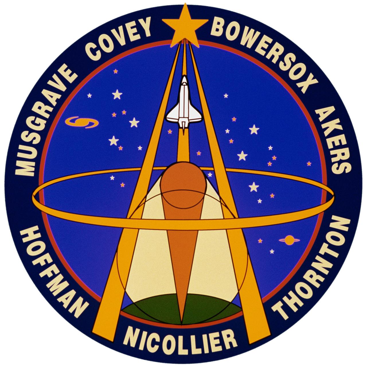
STS061-S-001 (1 Oct. 1993) --- Designed by the crew members, the STS-61 crew insignia depicts the astronaut symbol superimposed against the sky with the Earth underneath. Also seen are two circles representing the optical configuration of the Hubble Space Telescope (HST). Light is focused by reflections from a large primary mirror and a smaller secondary mirror. The light is analyzed by various instruments and, according to the crew members, "brings to us on Earth knowledge about planets, stars, galaxies and other celestial objects, allowing us to better understand the complex physical processes at work in the universe." The space shuttle Endeavour is also represented as the fundamental tool that allows the crew to perform the first servicing of the Hubble Space Telescope so its scientific deep space mission may be extended for several years to come. The overall design of the emblem, with lines converging to a high point, is also a symbolic representation of the large-scale Earth-based effort -- which involves space agencies, industry and the universities -- to reach goals of knowledge and perfection. The NASA insignia design for space shuttle flights is reserved for use by the astronauts and for other official use as the NASA Administrator may authorize. Public availability has been approved only in the forms of illustrations by the various news media. When and if there is any change in this policy, which is not anticipated, the change will be publicly announced. Photo credit: NASA

STS057-S-001 (February 1993) --- Designed by the crew members, the STS-57 crew patch depicts the space shuttle Endeavour maneuvering to retrieve the European Space Agency's (ESA) microgravity experiment satellite EURECA. SpaceHab - the first commercial space laboratory - is depicted in the cargo bay, and its characteristic shape is represented by the inner red border of the patch. The three gold plumes surrounded by the five stars trailing EURECA are suggestive of the United States astronaut logo. The five gold stars together with the shape of the orbiter's mechanical arm form the mission's numerical designation. The six stars on the American flag represent the United States astronauts who comprise the crew. With detailed input from the crew members, the final artwork was accomplished by artist Tim Hall. The NASA insignia design for space shuttle flights is reserved for use by the astronauts and for other official use as the NASA Administrator may authorize. Public availability has been approved only in the form of illustrations by the various news media. When and if there is any change in this policy, which we do not anticipate, it will be publicly announced. Photo credit: NASA
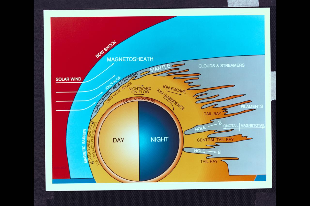
Graphic Art Venus - Day - Night drawing showing solar wind, bow shock, magnetosheath, clouds and streamers Pioneer Venus SP-461 fig 6-28 Interaction of the solar wind with the atmosphere of Venus as termined from Pioner Venus experiments and observations
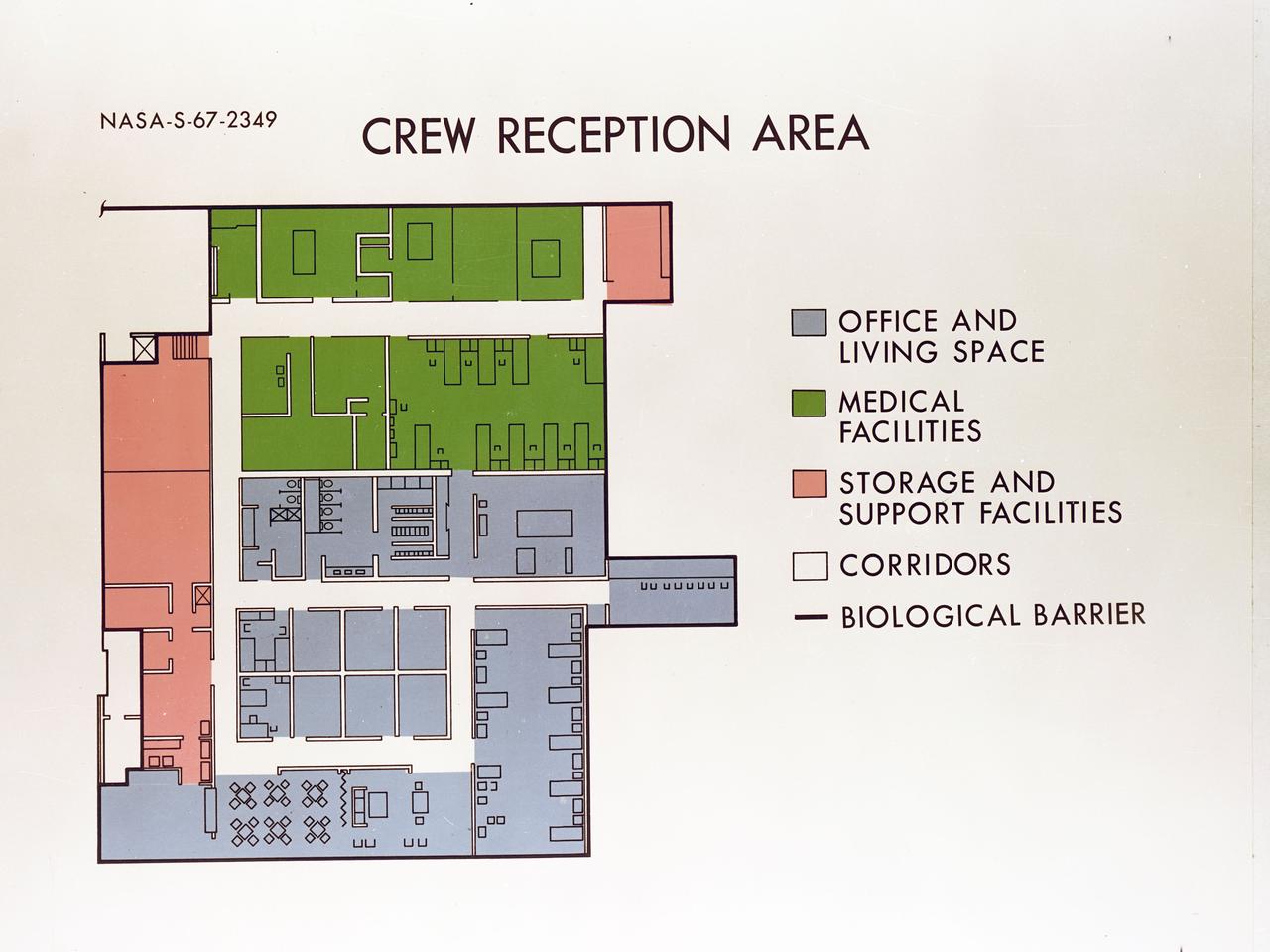
Artist's concept depicting the floor plan of the Crew Reception Area of the Lunar Receiving Laboratory (LRL), bldg 37.
STS065-S-001 (March 1994) --- Designed by the crew members, the STS-65 insignia features the International Microgravity Laboratory (IML-2) mission and its Spacehab module which will fly aboard the space shuttle Columbia. IML-2 is reflected in the emblem by two gold stars shooting toward the heavens behind the IML lettering. The space shuttle Columbia is depicted orbiting the logo and reaching into space, with Spacehab on an international quest for a better understanding of the effects of spaceflight on materials processing and life sciences. The NASA insignia design for space shuttle flights is reserved for use by the astronauts and for other official use as the NASA Administrator may authorize. Public availability has been approved only in the forms of illustrations by the various news media. When and if there is any change in this policy, which is not anticipated, the change will be publicly announced. Photo credit: NASA
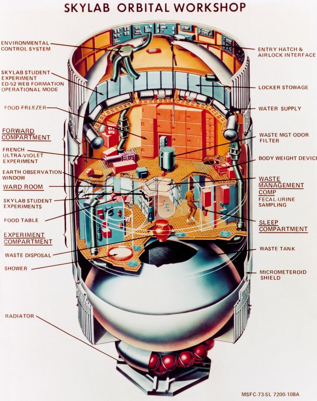
S73-23919 (May 1973) --- An artist's concept illustrating a cutaway view of the Skylab 1 Orbital Workshop (OWS). The OWS is one of the five major components of the Skylab 1 space station cluster which was launched by a Saturn V on May 14, 1973 into Earth orbit. Photo credit: NASA
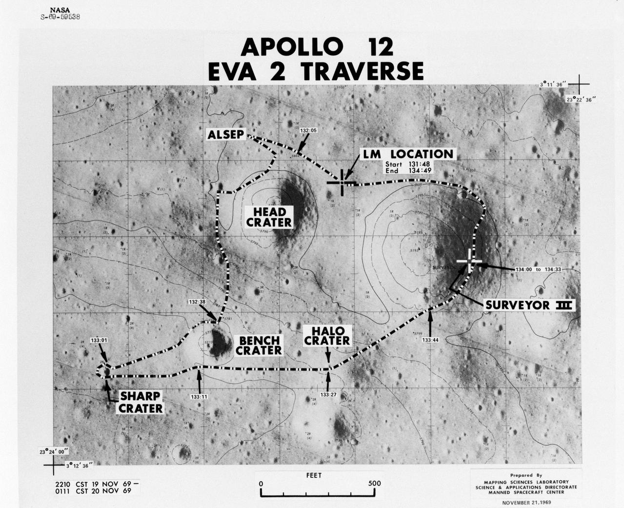
S69-59538 (November 1969) --- Apollo 12 extravehicular activity (EVA-2) Traverse Overlay.
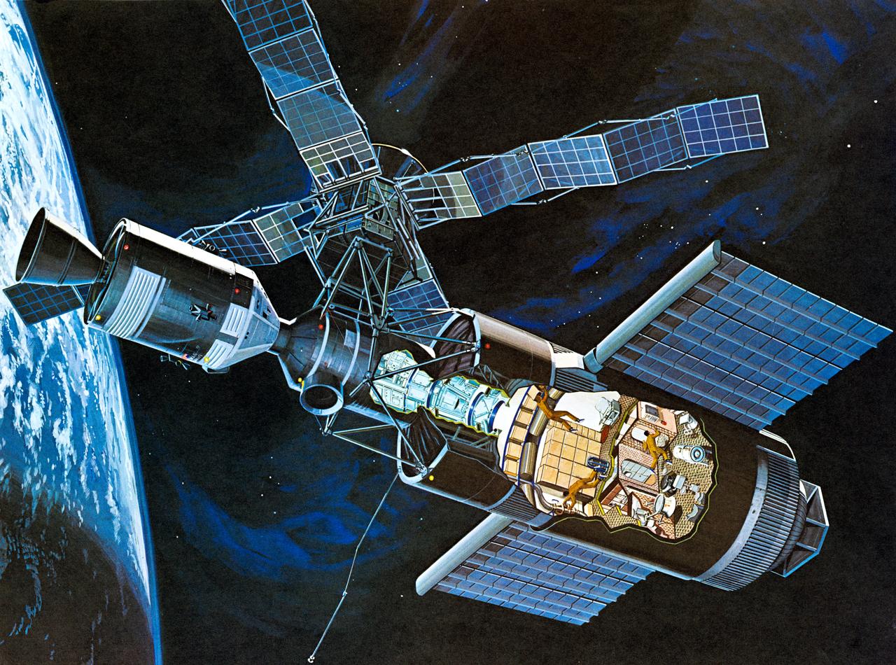
S71-52192 (1971) --- An artist's concept of the Skylab space station cluster in Earth's orbit. The cutaway view shows astronaut activity in the Orbital Workshop (OWS). The Skylab cluster is composed of the OWS, Airlock Module (AM), Multiple Docking Adapter (MDA), Apollo Telescope Mount (ATM), and the Command and Service Module (CSM). Photo credit: NASA
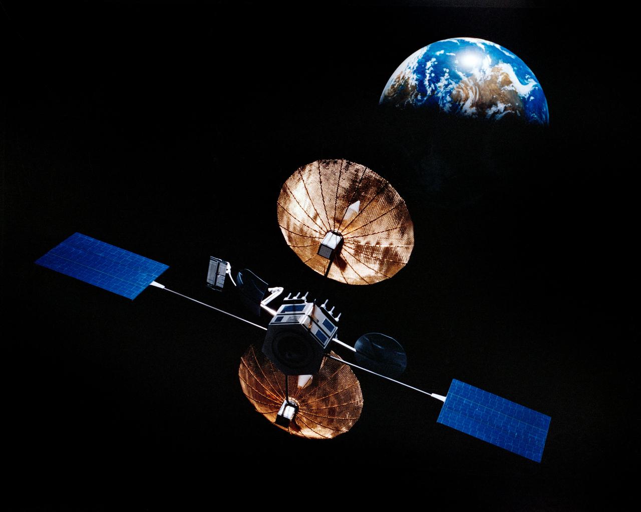
Artist concept of satellite with solar panels deployed in orbit above the earth.
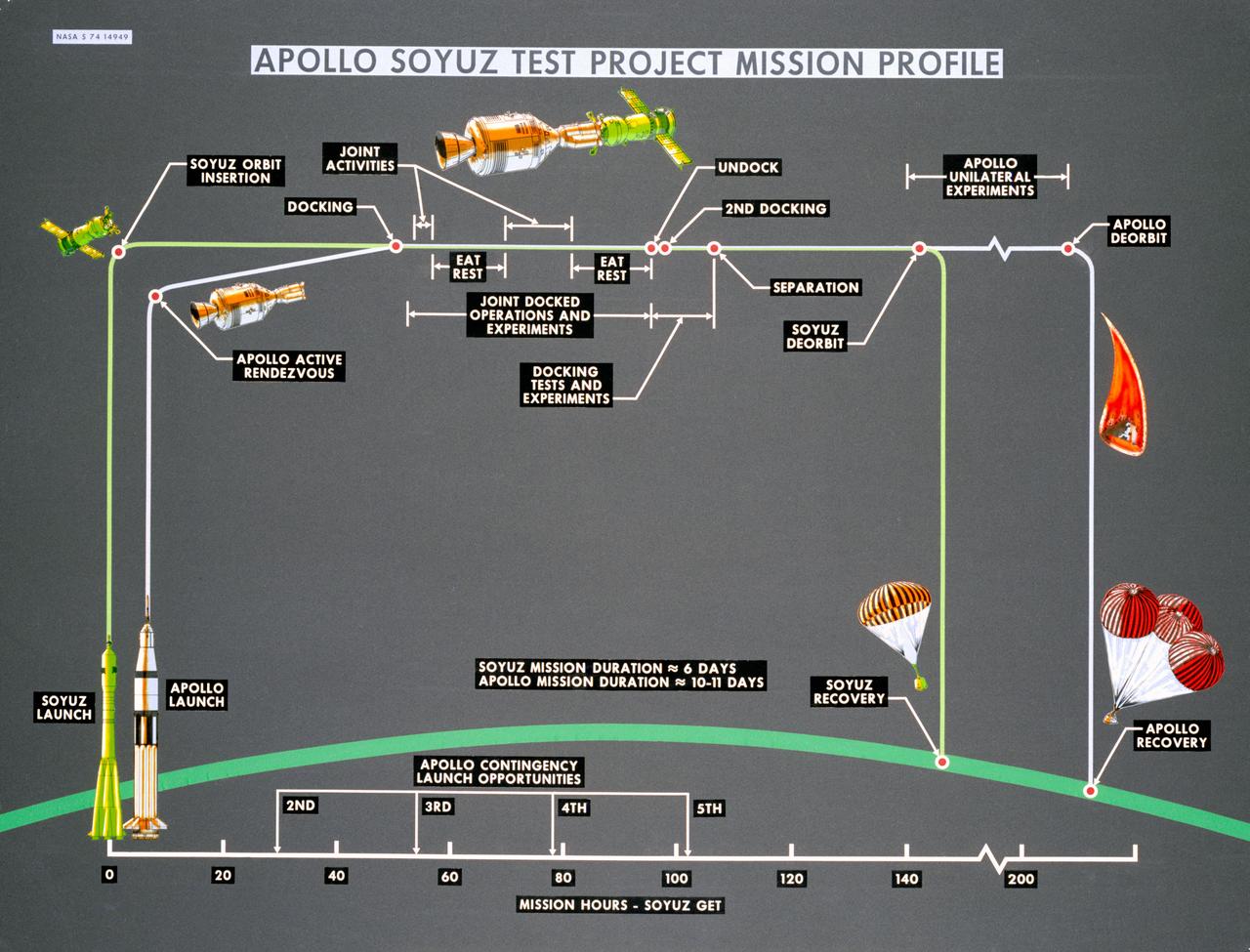
S74-14949 (October 1974) --- Artist?s drawings and call-outs depict phases of the joint U.S.-USSR Apollo-Soyuz Test Project, an Earth-orbital mission which will feature rendezvous and docking of the respective spacecraft of the two nations. ASTP crewmen for the USSR include Aleksey A. Leonov and Valeriy N. Kubasov. The astronaut team includes astronauts Thomas P. Stafford, Vance D. Brand and Donald K. Slayton. The mission is scheduled to take place in summer 1975.
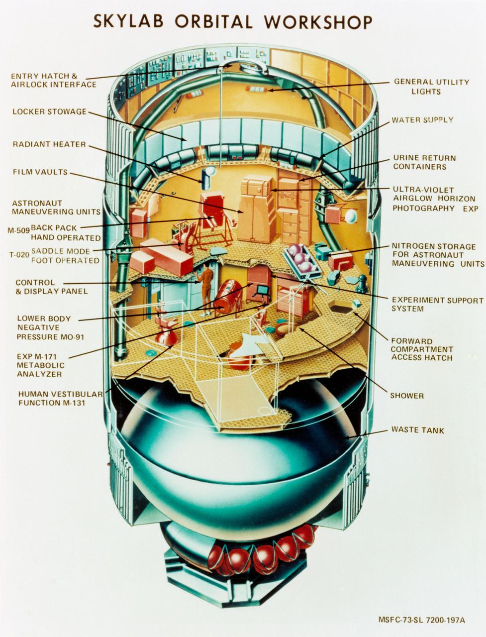
S73-23918 (May 1973) --- An artist's concept illustrating a cutaway view of the Skylab 1 Orbital Workshop (OWS). The OWS is one of the five major components of the Skylab 1 space station cluster which was launched by a Saturn V on May 14, 1973 into Earth orbit. Photo credit: NASA

NASA Administrator Bill Nelson, right, speaks with Jenny Mottar, art director for NASA’s Science Mission Directorate, and Kevin Miller, senior graphic designer in the Sciences and Exploration Directorate at NASA’s Goddard Space Flight Center, about the agency’s Earth Day poster as NASA celebrates Earth Day, Friday, April 19, 2024, in the Earth Information Center at the Mary W. Jackson NASA Headquarters building in Washington. Photo Credit: (NASA/Joel Kowsky)
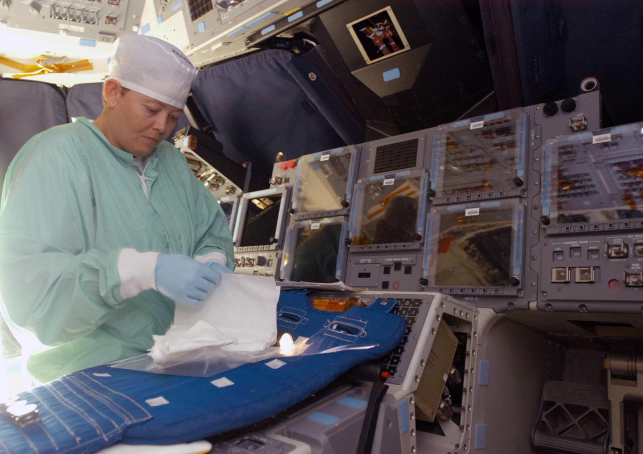
KENNEDY SPACE CENTER, FLA. - Carmen Prater, with United Space Alliance, works on the flight deck of the orbiter Endeavour in bay 2 of the Orbiter Processing Facility. She wears a “bunny suit,” clean room attire required for anyone coming in close proximity to the orbiter. Endeavour is undergoing major modifications, which include inspecting more than 150 miles of wiring, bonding 1,000 thermal tiles, and installing the Multifunction Electronic Display Subsystem - a state-of-the-art “glass cockpit.” The full-color, flat-panel MEDS upgrade improves crew/orbiter interaction with easy-to-read, graphic portrayals of key flight indicators like attitude display and mach speed.
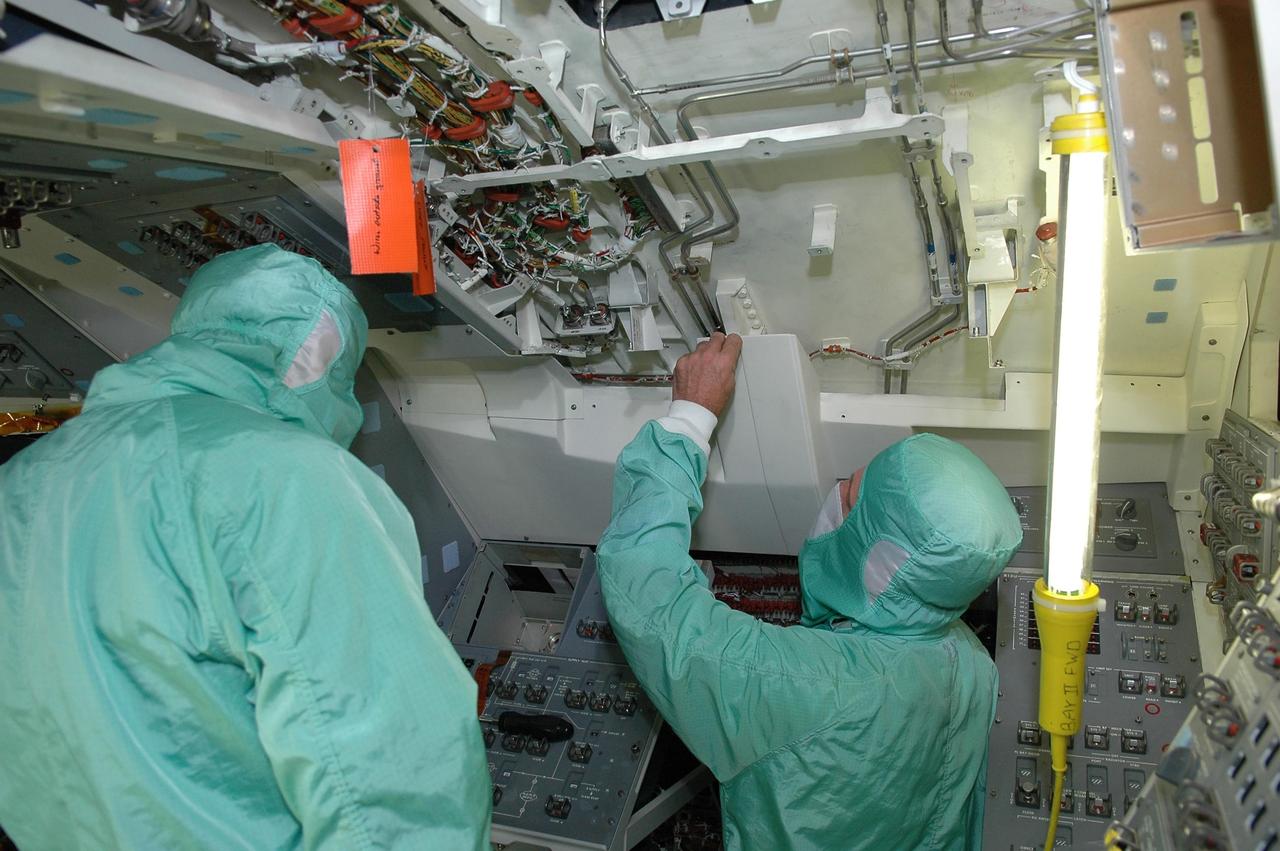
KENNEDY SPACE CENTER, FLA. - In bay 2 of the Orbiter Processing Facility, workers are installing the Multifunction Electronic Display Subsystem - a state-of-the-art “glass cockpit” - on the orbiter Endeavour. The “bunny suits” they are wearing are clean room attire required for anyone coming in close proximity to the orbiter. The full-color, flat-panel MEDS upgrade improves crew/orbiter interaction with easy-to-read, graphic portrayals of key flight indicators like attitude display and mach speed. Endeavour is undergoing major modifications, which include inspecting more than 150 miles of wiring and bonding 1,000 thermal tiles, along with installing the display system.
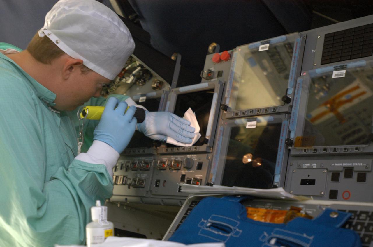
KENNEDY SPACE CENTER, FLA. - Carmen Prater, with United Space Alliance, cleans a screen on the flight deck of the orbiter Endeavour in bay 2 of the Orbiter Processing Facility. She wears a “bunny suit,” clean room attire required for anyone coming in close proximity to the orbiter. Endeavour is undergoing major modifications, which include inspecting more than 150 miles of wiring, bonding 1,000 thermal tiles, and installing the Multifunction Electronic Display Subsystem - a state-of-the-art “glass cockpit.” The full-color, flat-panel MEDS upgrade improves crew/orbiter interaction with easy-to-read, graphic portrayals of key flight indicators like attitude display and mach speed.
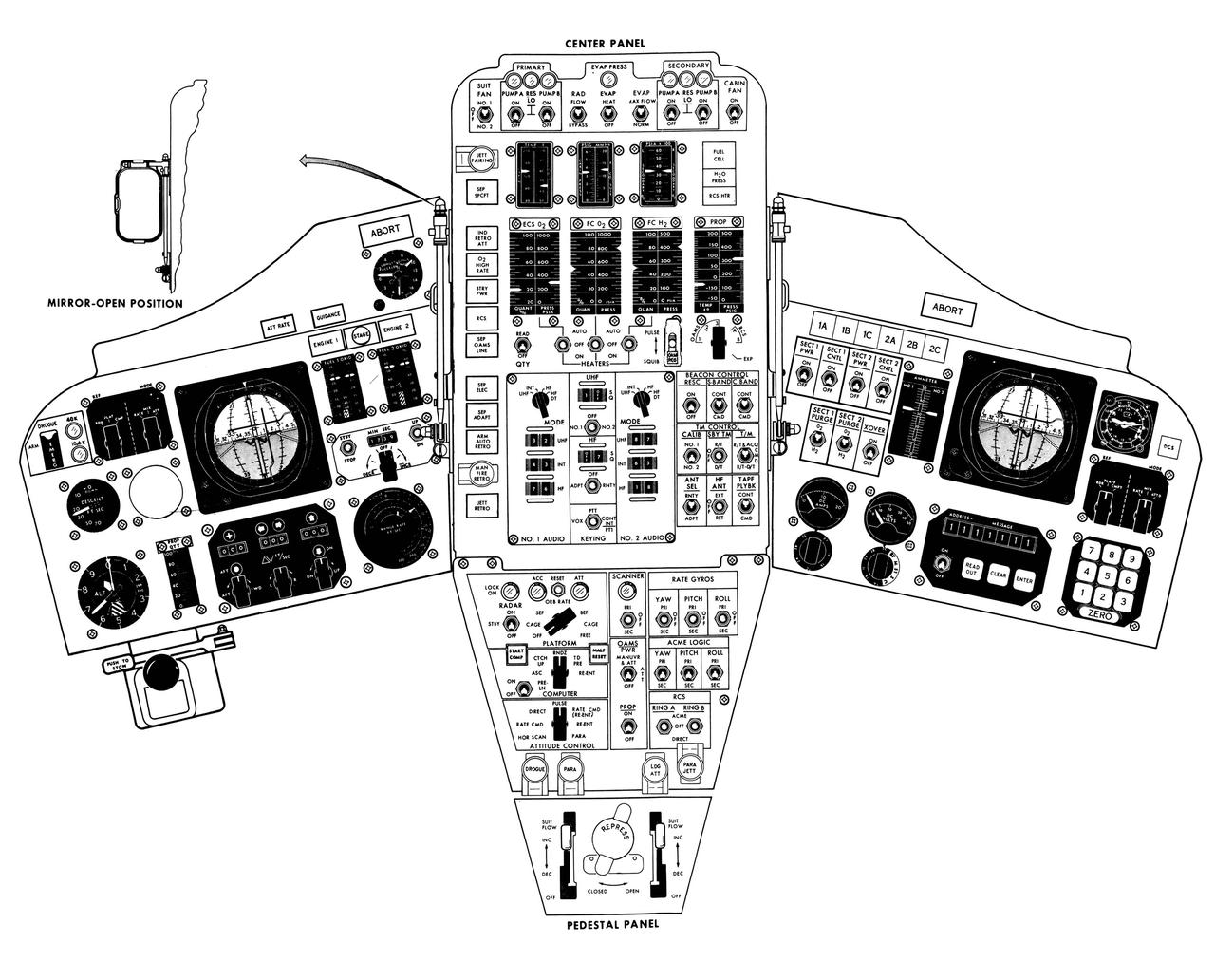
S65-14095 (1965) --- Artist concept of the Gemini spacecraft control panel.

S73-02395 (August 1973) --- An artist?s concept illustrating an Apollo-type spacecraft (on left) about to dock with a Soviet Soyuz-type spacecraft. A recent agreement between the United States and the Union of Soviet Socialist Republics provides for the docking in space of the Soyuz and Apollo-type spacecraft in Earth orbit in 1975. The joint venture is called the Apollo-Soyuz Test Project.
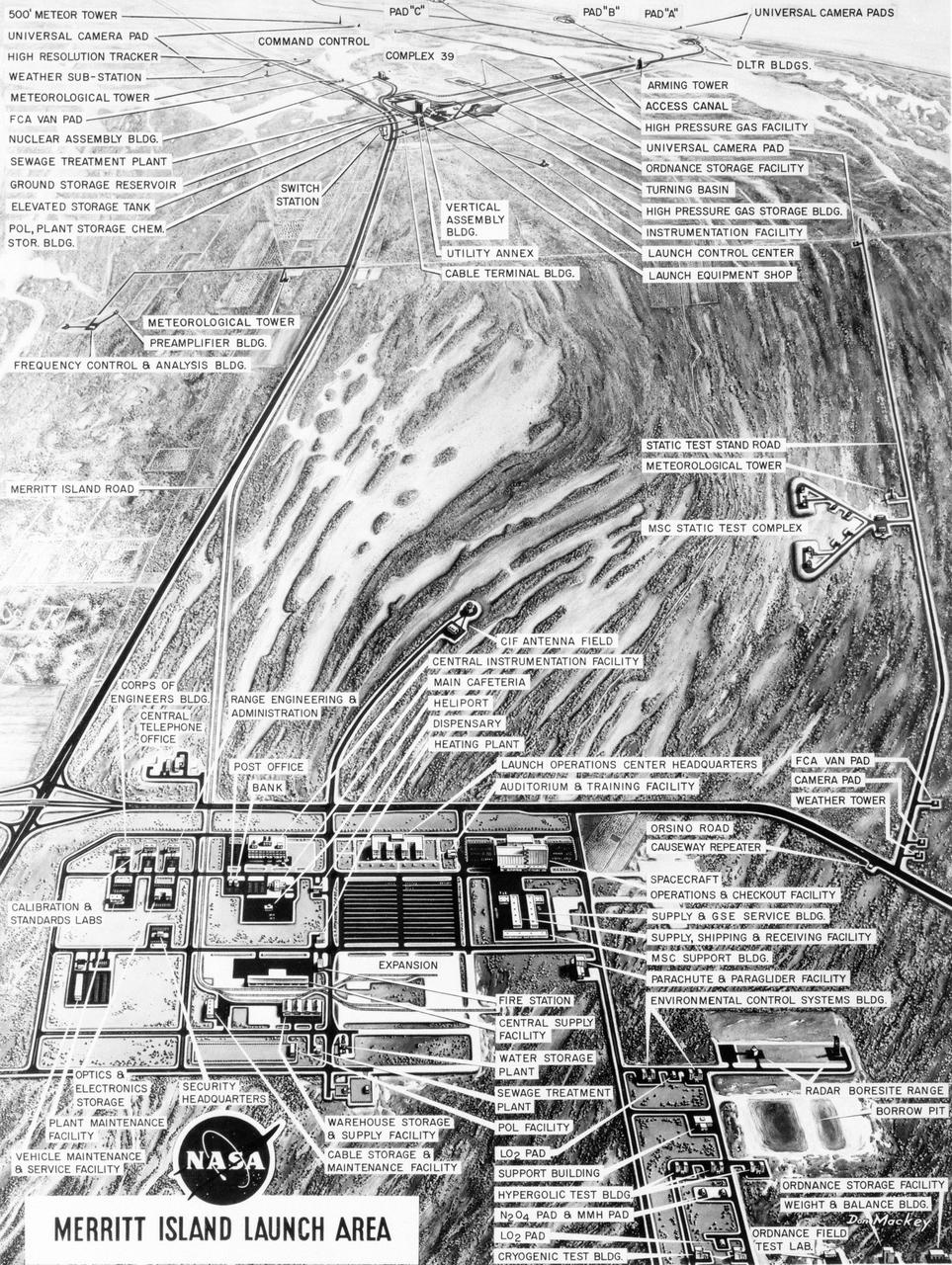
S63-23618 (December 1963) --- Aerial oblique artist concept of the Merritt Island Launch Complex, Merritt Island, Florida. Photo credit: NASA
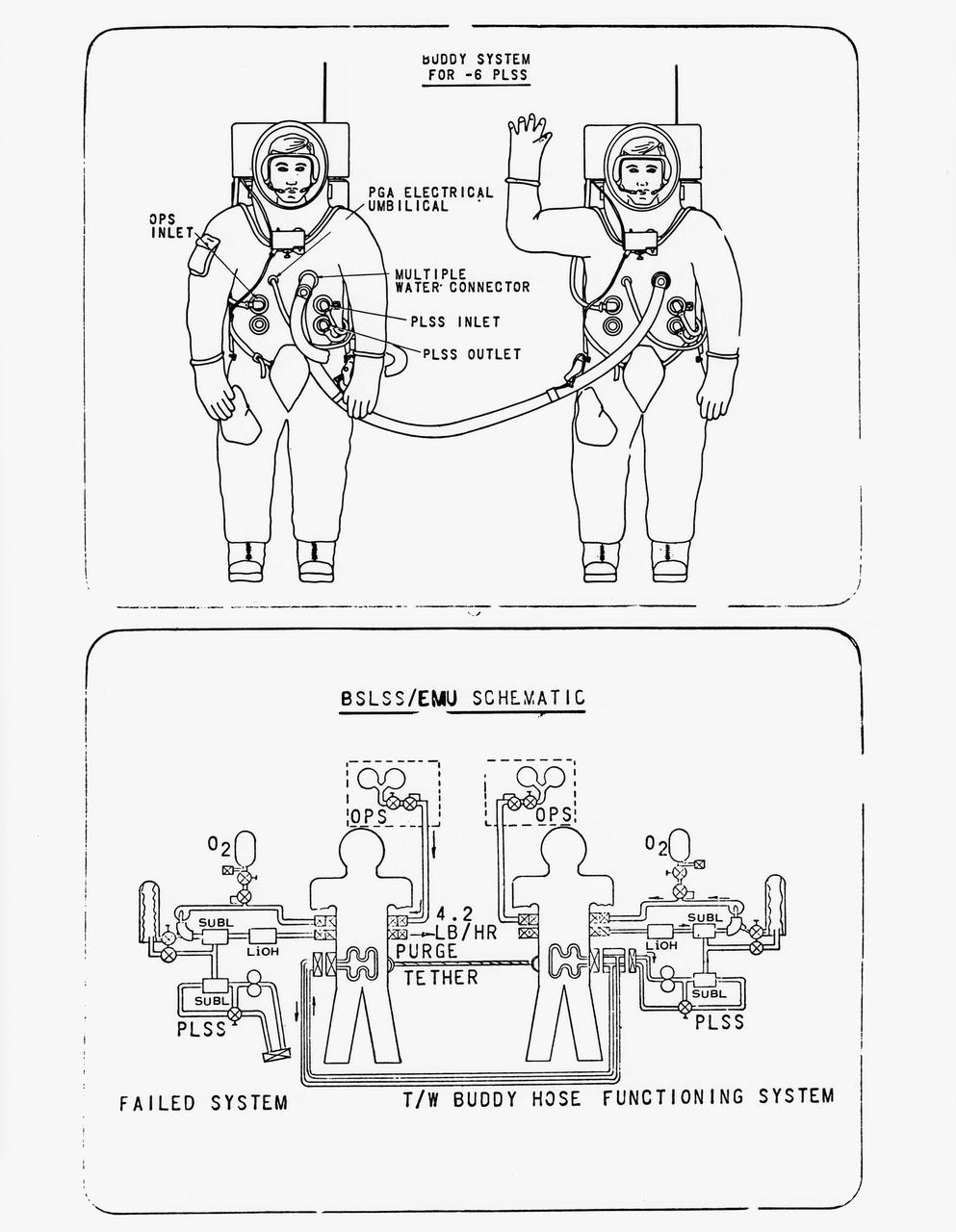
S70-56965 (December 1970) --- Drawing of the newly developed Buddy Secondary Life Support System (BSLSS). The life-sustaining system will be provided for the first time on the Apollo 14 lunar landing mission. The two flexible hoses, to be used on the second Apollo 14 extravehicular activity (EVA), will be among the paraphernalia on the Modular Equipment Transporter (MET) or two-wheeled workshop, and readily accessible in an emergency. During EVAs the Portable Life Support System (PLSS) supplies the astronaut with breathing and suit-pressurizing oxygen and water flow for the liquid-cooling garment -- a suit of knitted long underwear with thin tubing woven in the torso and limbs. The tubes carry water from a reservoir in the PLSS, and the circulating water serves to carry the astronaut's metabolic heat to a heat exchanger in the PLSS. Before the BSLSS was devised, the emergency tank was required to furnish not only suit pressure and breathing oxygen, but also cooling through a high oxygen flow rate. The BSLSS, by sharing the water supply between the two crewmen, stretches the time of the emergency oxygen from about 40 minutes to 60 to 75 minutes.
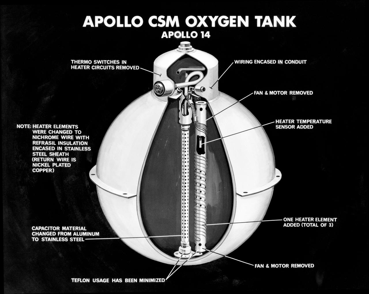
S71-16745 (January 1971) --- An artist's concept illustrating a cutaway view of one of the three oxygen tanks of the Apollo 14 spacecraft. This is the new Apollo oxygen tank design, developed since the Apollo 13 oxygen tank explosion. Apollo 14 has three oxygen tanks redesigned to eliminate ignition sources, minimize the use of combustible materials, and simplify the fabrication process. The third tank has been added to the Apollo 14 Service Module, located in the SM's sector one, apart from the pair of oxygen tanks in sector four. Arrows point out various features of the oxygen tank.

The rising sun signifies the dawn of a new era of human Spaceflight, the first phase of the United States/Russian space partnership, Shuttle-Mir. Mir is shown in its proposed final on orbit configuration. The Shuttle is shown in a generic tunnel/Spacehab configuration. The Shuttle/Mir combination, docked to acknowledge the union of the two space programs, orbits over an Earth devoid of any definable features or political borders to emphasize Earth as the home planet for all humanity. The individual stars near the Space Shuttle and the Russian Mir Space Station represent the previous individual accomplishments of Russia's space program and that of the United States. The binary star is a tribute to the previous United States-Russian joint human Spaceflight program, the Apollo-Soyuz Test Project (ASTP). The flags of the two nations are symbolized by flowing ribbons of the national colors interwoven in space to represent the two nations joint exploration of space. NASA SHUTTLE and PKA MNP are shown in the stylized logo fonts of the two agencies that are conducting this program.
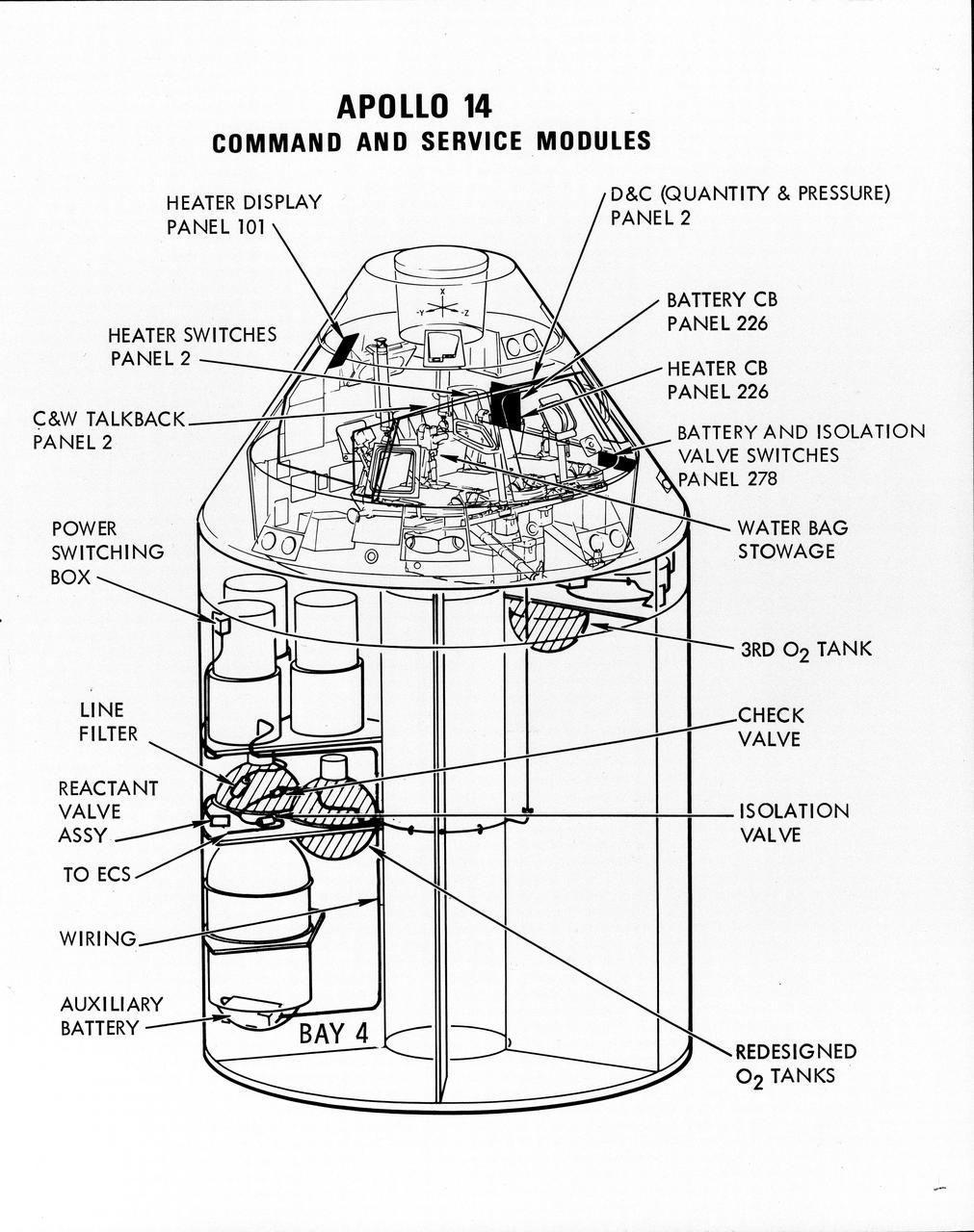
S71-16823 (January 1971) --- A line drawing illustrating a cutaway view of the Apollo 14 Command and Service Modules, showing the engineering changes in the CSM which were recommended by the Apollo 13 Review Board. (The Apollo 13 abort was caused by a short circuit and wiring overheating in one of the SM cryogenic oxygen tanks.) The major changes to the Apollo 14 CSM include adding a third cryogenic oxygen tank installed in a heretofore empty bay (in sector one) of the SM, addition of an auxiliary battery in the SM as a backup in case of fuel cell failure, and removal of destratification fans in the cryogenic oxygen tanks and removal of thermostat switches from the oxygen tank heater circuits. Provision for stowage of an emergency five-gallon supply of drinking water has been added to the CM.

S74-05269 (December 1974) --- An artist?s drawing illustrating the internal arrangement of the Apollo and Soyuz spacecraft in Earth orbit in a docked configuration. The three American Apollo crewmen and the two Soviet Soyuz crewmen will transfer to each other?s spacecraft during the July 1975 ASTP mission. The four Apollo-Soyuz Test Project visible components are, left to right, the Apollo Command Module, the Docking Module, the Soyuz Orbital Module and the Soyuz Descent Vehicle.
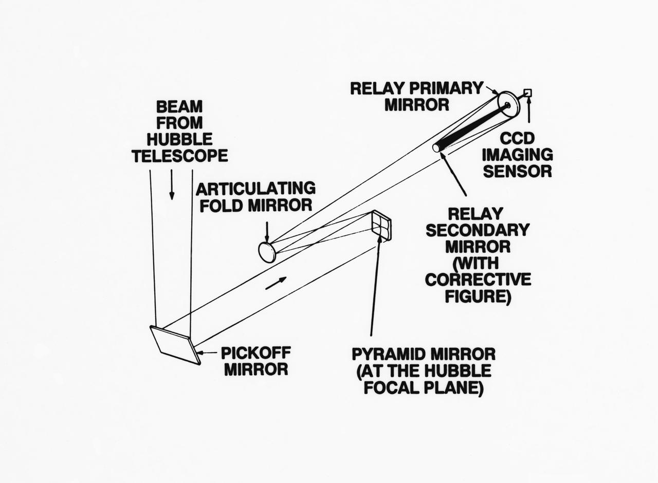
S93-33258 (15 Mar 1993) --- An optical schematic diagram of one of the four channels of the Wide Field\Planetary Camera-2 (WF\PC-2) shows the path taken by beams from the Hubble Space Telescope (HST) before an image is formed at the camera's charge-coupled devices. A team of NASA astronauts will pay a visit to the HST later this year, carrying with them the new WF/PC-2 to replace the one currently on the HST. The Jet Propulsion Laboratory in Pasadena, California has been working on the replacement system for several months. See NASA photo S93-33257 for a close-up view of tiny articulating mirrors designed to realign incoming light in order to make certain the beams fall precisely in the middle of the secondary mirrors.
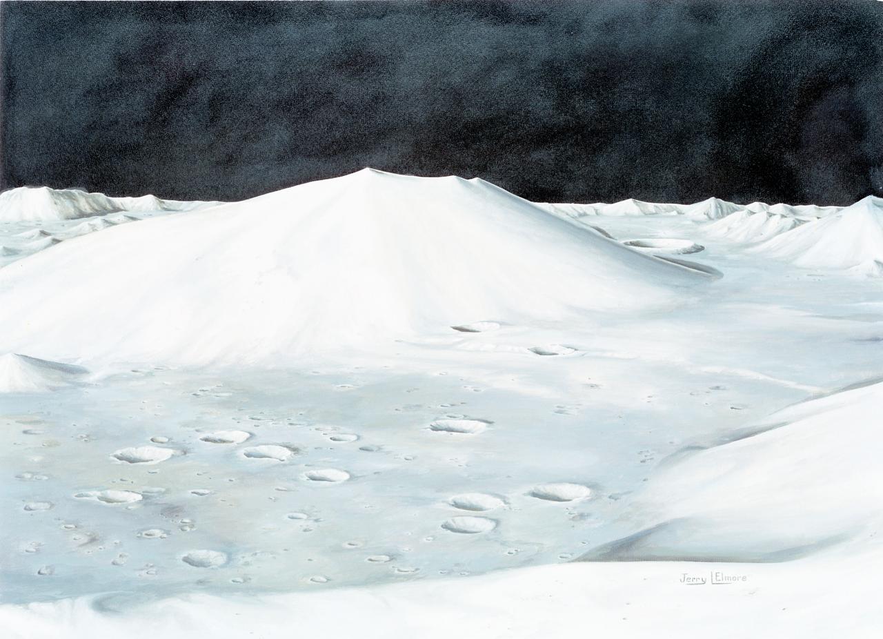
S72-49761 (October 1972) --- An artist's concept illustrating the topographical layout of the Taurus-Littrow landing site of the Apollo 17 lunar landing mission. The Lunar Module touchdown point is in the center of the smooth area in the middle of the picture. The imposing mountain in the center is South Massif. A portion of North Massif is in the lower right corner of the photograph. Note the ridge-like feature extending from South Massif to North Massif. The southern portion of the ridge is called Lee Scarp and the northerly portion Lincoln Scarp. (This concept is by JSC artist Jerry Elmore).
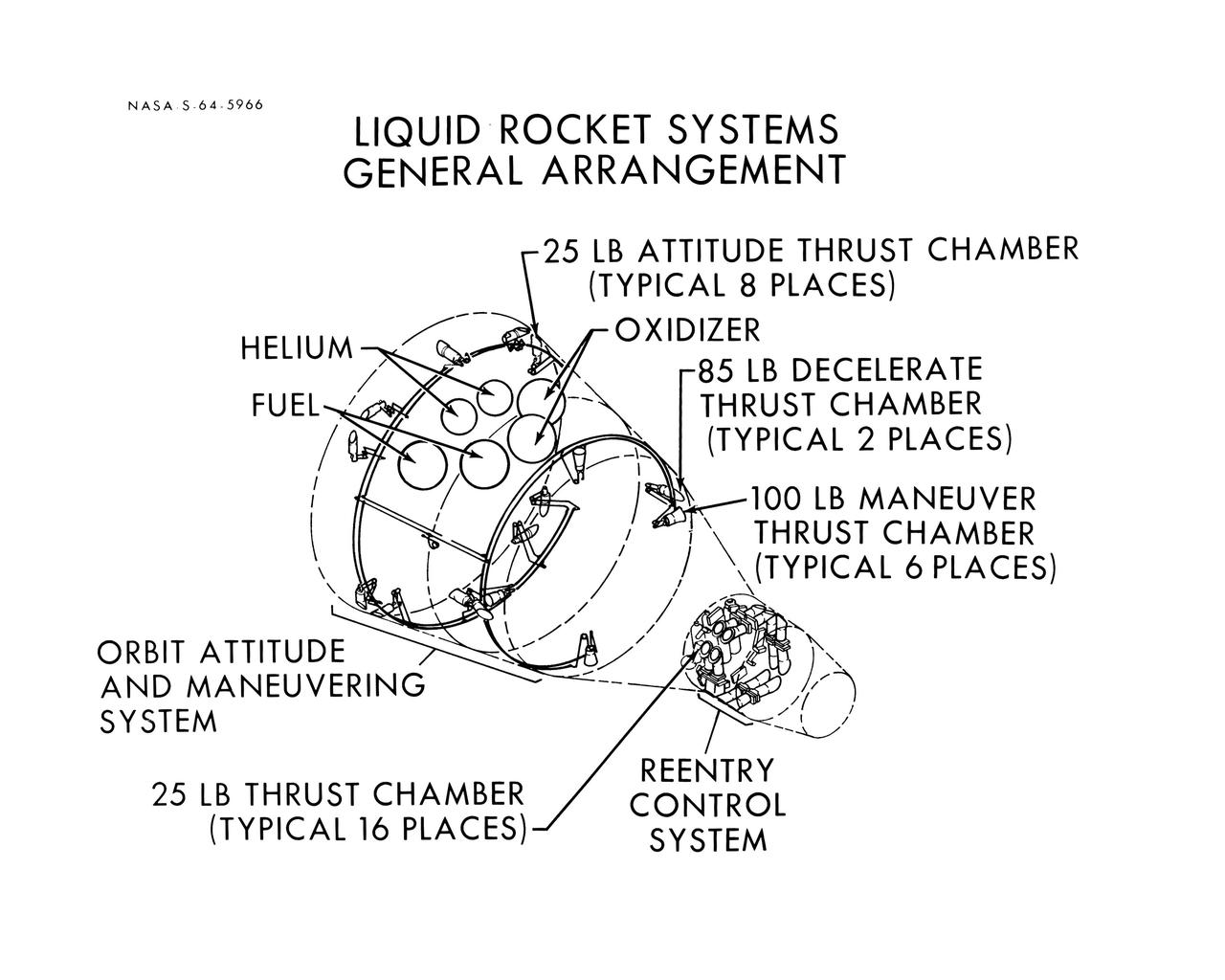
S64-05966 (1964) --- Diagram shows the general arrangement of the liquid rocket systems on the Gemini spacecraft are shown. The locations of the 25-pound, 85-pound and 100-pound thrusters of the orbital attitude and maneuver system and the 25-pound thrusters of the re-entry control system are shown.
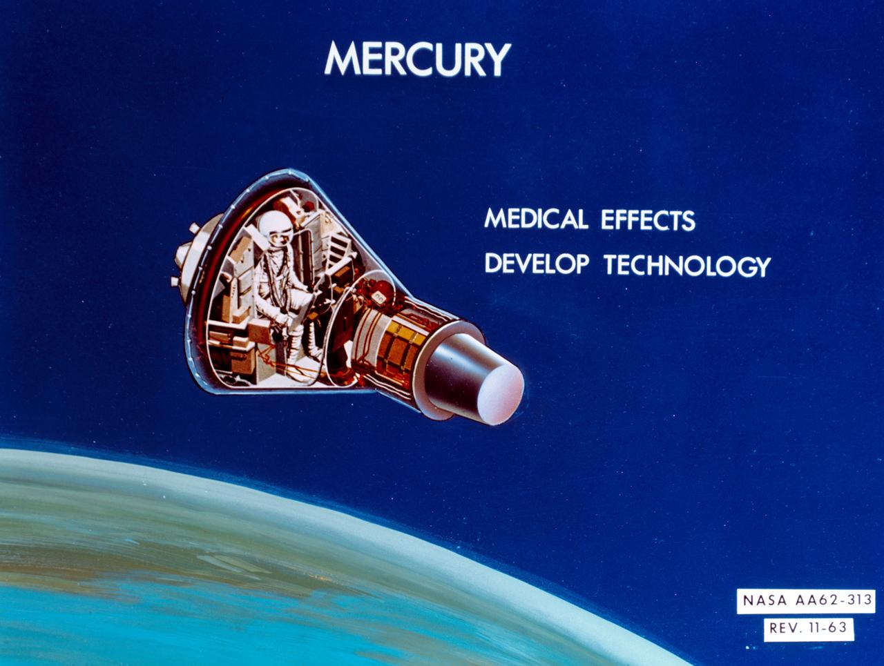
S64-14286 (11 Feb. 1964) --- An artist's concept of Mercury: Medical effects; develop technology. Photo credit: NASA
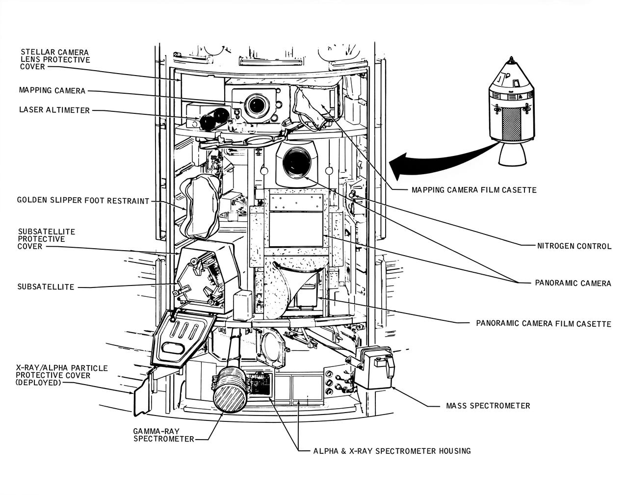
A line drawing illustrating the layout of the Scietific Instrument Module (SIM) of the Apollo 16 Service Module. Shown here is the location in the SIM bay of the equipment for each orbital experiment. Arrows point to various components of the SIM bay. The sensors for the gamma ray spectrometer and the mas spectrometer both extend outward on a boom about 25 feet when the instruments are in use. The subsatellite is launched while the Service Module is in orbit around the moon. The film cassettes must be retrieved prior to Command Module/Service Module separation.
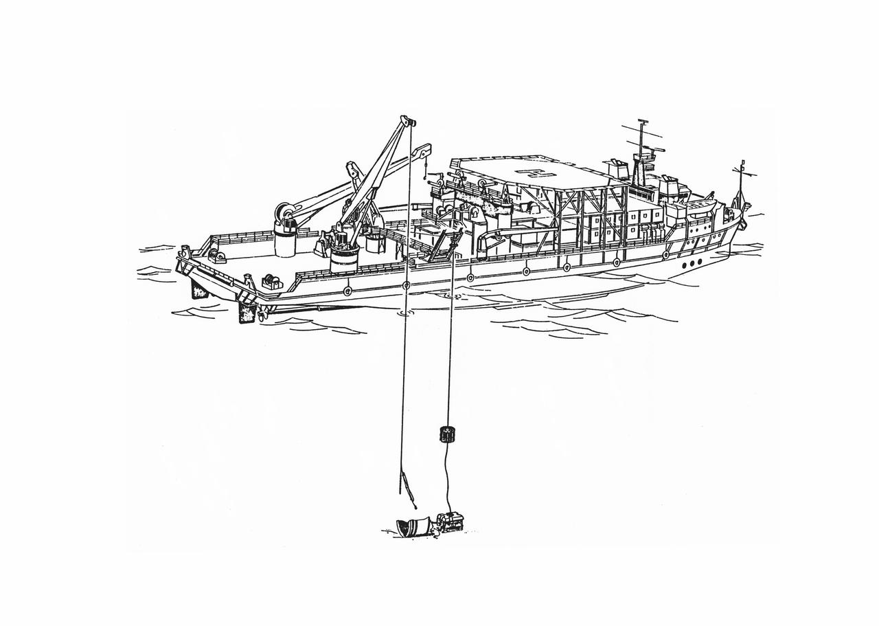
S86-30088 (March 1986) --- Salvage operations offshore of Kennedy Space Center, are depicted in this artist’s concept showing a grapple and recovery fixture (left) being directed through the use of a remote video system suspended from the recovery ship. Photo credit: NASA

51D-09-014 (12-19 April 1985) --- U.S. Senator E. J. (Jake) Garn (left), payload specialist; and Karol J. Bobko, mission commander, show a copy of a cartoon from the Doonesbury strip of Garry Trudeau. The senator had been the subject of a series of Trudeau's creations prior to 51-D. The single enlarged panel is autographed by the crewmembers.
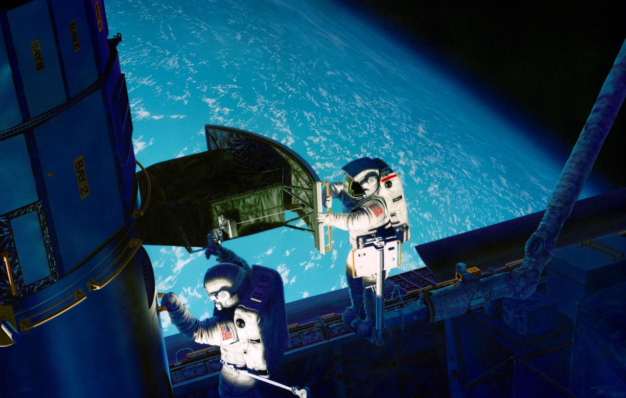
S93-48826 (November 1993) --- This artist's rendition of the 1993 Hubble Space Telescope (HST) servicing mission shows astronauts installing the new Wide Field/Planetary Camera (WF/PC 2). The instruments to replace the original camera and contains corrective optics that compensate for the telescope's flawed primary mirror. During the 11-plus day mission, astronauts are also scheduled to install the Corrective Optics Space Telescope Axial Replacement (COSTAR) -- an optics package that focuses and routes light to the other three instruments aboard the observatory -- a new set of solar array panels, and other hardware and components. The artwork was done for JPL by Paul Hudson.
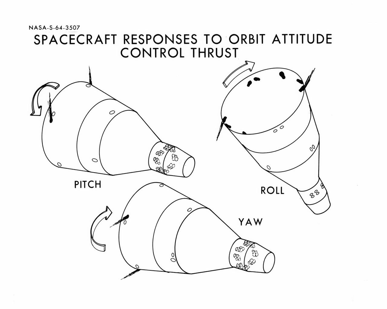
S64-03507 (1964) --- Diagrams shows Gemini spacecraft responses to orbital attitude systems's thrusters. Firing of appropriate combination of the thrusters cause pitch, roll and yaw.
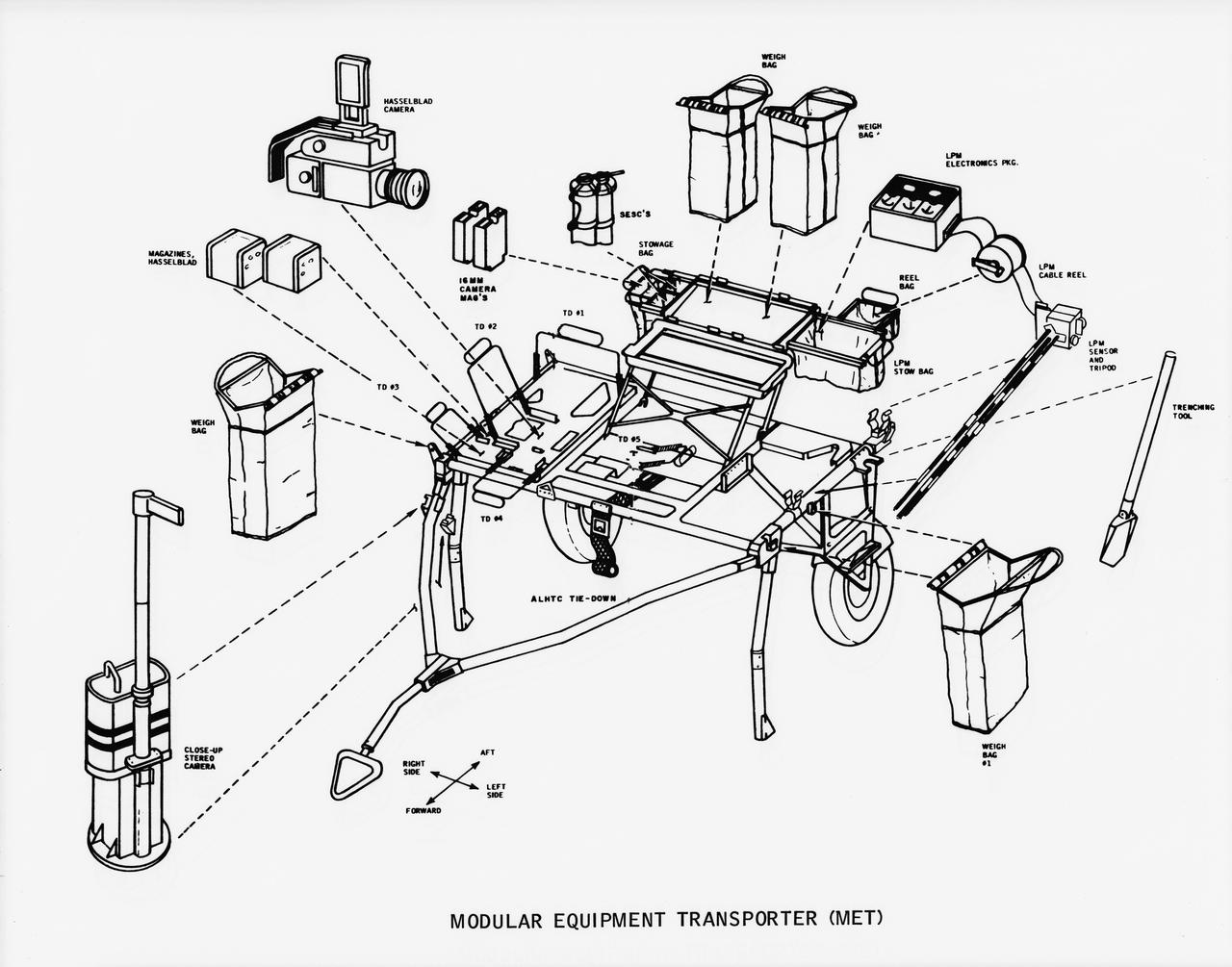
S70-50762 (November 1970) --- A line drawing illustrating layout view of the modular equipment transporter (MET) and its equipment. A MET (or Rickshaw, as it has been nicknamed) will be used on the lunar surface for the first time during the Apollo 14 lunar landing mission. The Rickshaw will serve as a portable workbench with a place for the Apollo lunar hand tools (ALHT) and their carrier, three cameras, two sample container bags, a special environment sample container (SESC), a lunar portable magnetometer (LPM) and spare film magazines.
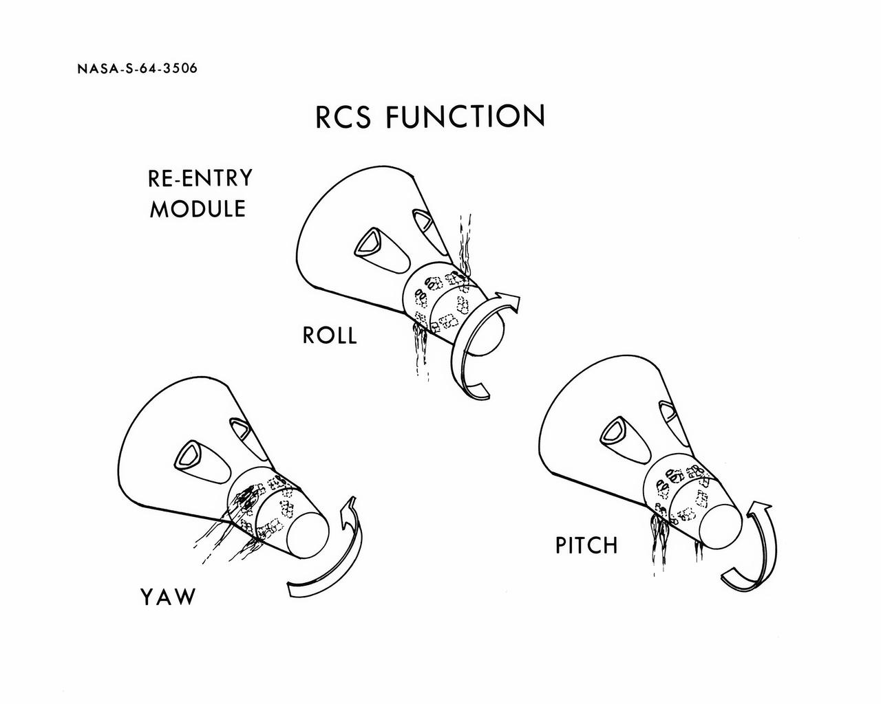
S64-03506 (1964) --- Diagrams shows Gemini spacecraft functions of the thrusters in the Gemini spacecraft's re-entry control system. Thrusters may be fired in various combinations to cause yaw, roll and pitch.
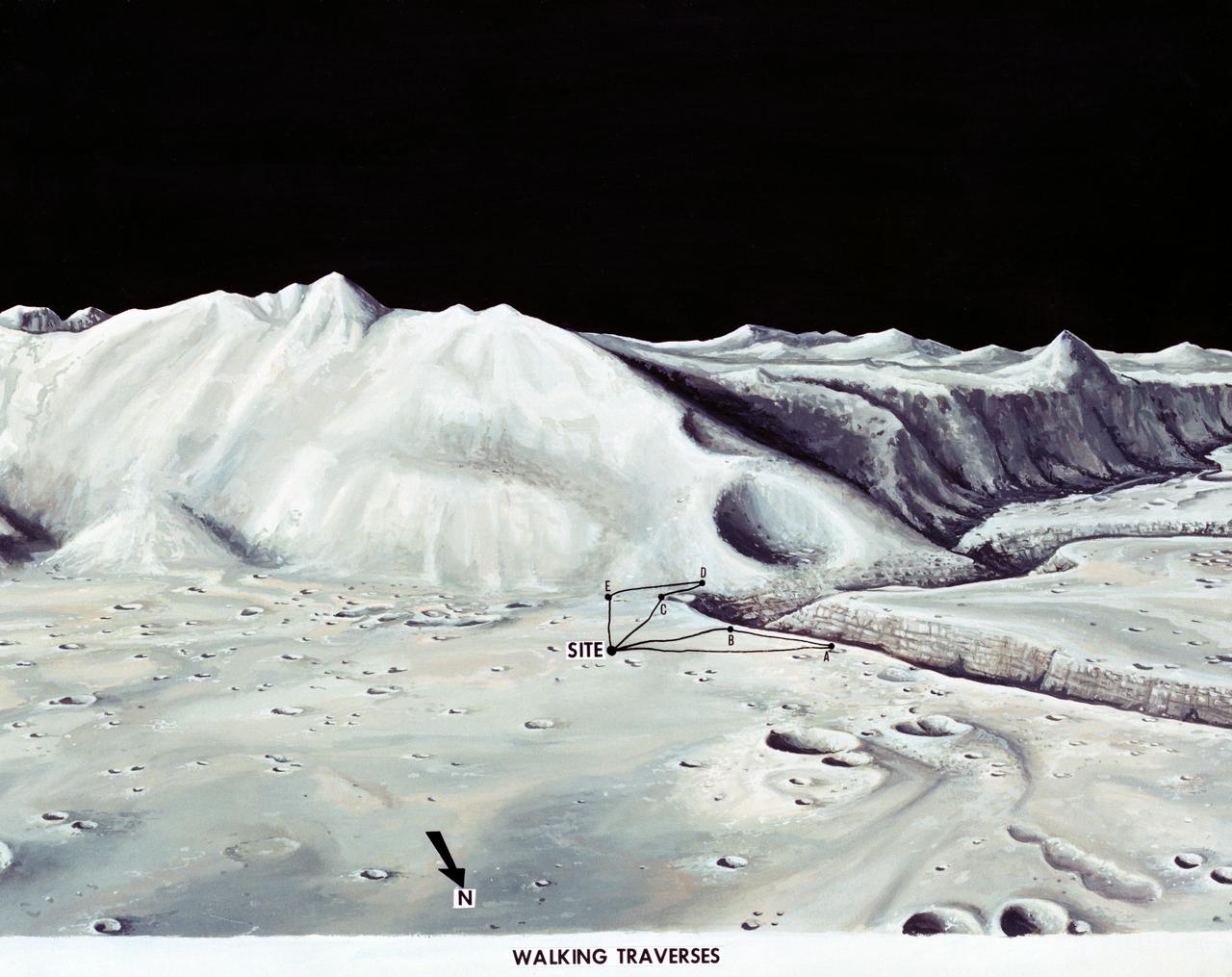
S71-33432 (1 July 1971) --- These alternative traverses can be carried out on foot. They will be used if the Lunar Roving Vehicle (LRV) becomes inoperative. This artist's concept showing part of the Hadley Rille and several of the Apennine Mountains was excerpted from "On the Moon with Apollo 15: A Guidebook to the Hadley-Apennine Region," by Gene Simmons. Artwork by Jerry Elmore.
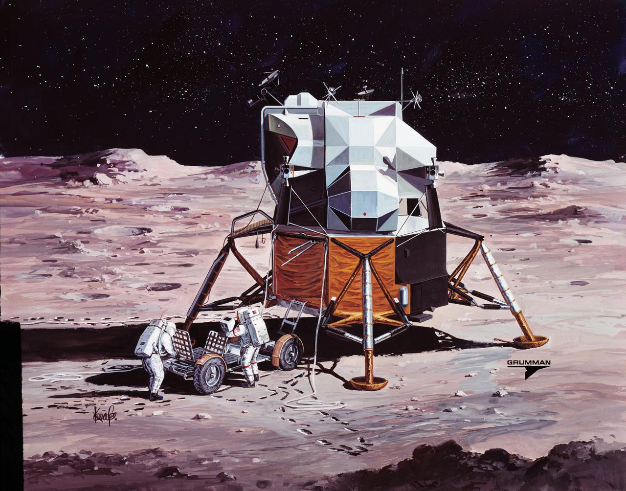
S71-38189 (26 June 1971) --- An artist's concept showing the final steps of readying the Apollo 15 Lunar Roving Vehicle (LRV) or Rover 1 for mobility on the lunar surface. Performing the last few LRV deployment tasks here are, left to right, astronauts James B. Irwin, lunar module pilot, and David R. Scott, commander. More specifically the tasks depicted here include the setting up of the seats and the total releasing of the LRV from the LM. (This is the fourth in a series of four Grumman Aerospace Corporation artist's concepts telling the lunar surface LRV deployment story for Apollo 15).
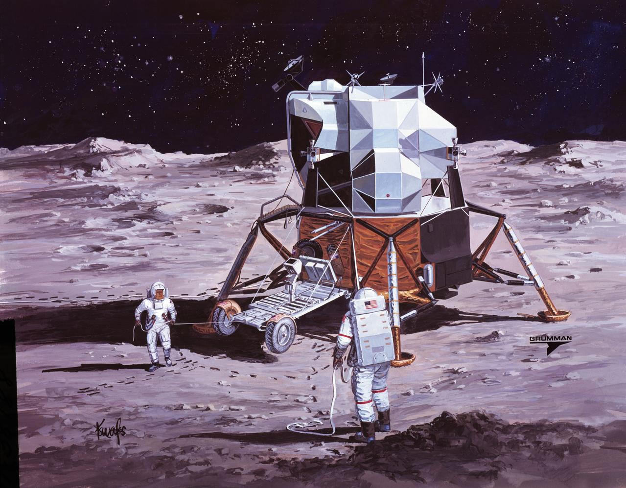
S71-38188 (26 June 1971) --- An artist's concept showing the Apollo 15 mission commander and the lunar module pilot performing deployment of the Lunar Roving Vehicle (LRV) on the lunar surface. The figure on the left represents astronaut James B. Irwin, lunar module pilot, who here is maintaining a constant pull on the deployment cable to help the LRV unfold, while astronaut David R. Scott (right), commander, pulls the tapes that lower the LRV to the surface. (This is the third in a series of Grumman Aerospace Corporation artist's concepts telling the lunar surface LRV deployment story of the Apollo 15 mission).
S71-16101 (January 1971) --- A Grumman Aerospace Corporation artist's concept of Apollo 14 crewmen, astronauts Alan B. Shepard Jr., commander, and Edgar D. Mitchell, lunar module pilot, as they set out on their first traverse. Shepard is pulling the Modularized Equipment Transporter (MET) which contains cameras, lunar sample bags, tools and other paraphernalia. Shepard has the Laser Ranging Retro-Reflector (LR-3) in his other hand. Mitchell is carrying the Apollo Lunar Surface Experiments Package (ALSEP) barbell mode.
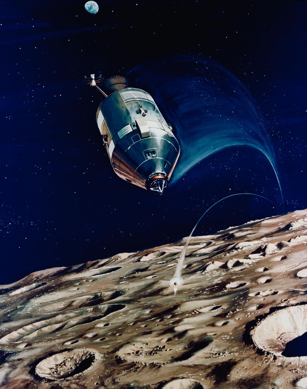
S71-16574 (11 Jan. 1971) --- An artist's concept depicting the Apollo 14 Command and Service Modules (CSM) circling the moon as the Lunar Module (LM) heads toward a lunar landing. While astronaut Stuart A. Roosa, command module pilot, remains with the CSM in lunar orbit, astronauts Alan B. Shepard Jr., commander; and Edgar D. Mitchell, lunar module pilot, will descend in the LM to explore an area in the rugged Fra Mauro highlands.
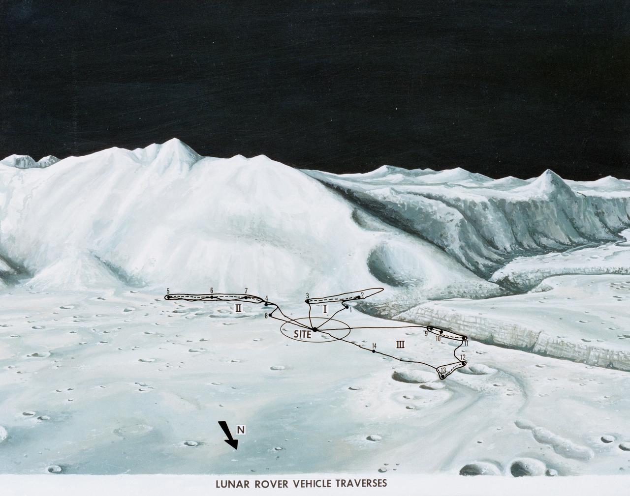
S71-33433 (1 July 1971) --- An artist's concept of the Hadley-Apennine landing site, depicting the traverses planned on the Apollo 15 lunar landing mission using the Lunar Roving Vehicle (LRV). The Roman numerals indicate the three periods of extravehicular activity (EVA). The Arabic numbers represent the station stops. This artist's concept was excerpted from "On the Moon with Apollo 15: A Guidebook to Hadley Rille and the Apennine Mountains," by Gene Simmons. The station stops indicated here are keyed to information given in the publication. Artwork by Jerry Elmore.

<b>RELEASE DATE: OCTOBER 9, 2007</b> <b>Credit: NASA/Goddard Space Flight Center/Reto Stöckli</b> A day’s clouds. The shape and texture of the land. The living ocean. City lights as a beacon of human presence across the globe. This amazingly beautiful view of Earth from space is a fusion of science and art, a showcase for the remote-sensing technology that makes such views possible, and a testament to the passion and creativity of the scientists who devote their careers to understanding how land, ocean, and atmosphere—even life itself—interact to generate Earth’s unique (as far as we know!) life-sustaining environment. Drawing on data from multiple satellite missions (not all collected at the same time), a team of NASA scientists and graphic artists created layers of global data for everything from the land surface, to polar sea ice, to the light reflected by the chlorophyll in the billions of microscopic plants that grow in the ocean. They wrapped these layers around a globe, set it against a black background, and simulated the hazy edge of the Earth’s atmosphere (the limb) that appears in astronaut photography of the Earth. The land surface layer is based on photo-like surface reflectance observations (reflected sunlight) measured by the Moderate Resolution Imaging Spectroradiometer (MODIS) on NASA’s Terra satellite in July 2004. The sea ice layer near the poles comes from Terra MODIS observations of daytime sea ice observed between August 28 and September 6, 2001. The ocean layer is a composite. In shallow water areas, the layer shows surface reflectances observed by Terra MODIS in July 2004. In the open ocean, the photo-like layer is overlaid with observations of the average ocean chlorophyll content for 2004. NASA’s Aqua MODIS collected the chlorophyll data. The cloud layer shows a single-day snapshot of clouds observed by Terra MODIS across the planet on July 29, 2001. City lights on Earth’s night side are visualized from data collected by the Defense Meteorological Satellite Program mission between 1994–1995. The topography layer is based on radar data collected by the Space Shuttle Endeavour during an 11-day mission in February of 2000. Topography over Antarctica comes from the Radarsat Antarctic Mapping Project, version 2. Most of the data layers in this visualization are available as monthly composites as part of NASA’s Blue Marble Next Generation image collection. The images in the collection appear in cylindrical projection (rectangular maps), and they are available at 500-meter resolution. The large images provided above are the full-size versions of these globes. In their hope that these images will inspire people to appreciate the beauty of our home planet and to learn about the Earth system, the developers of these images encourage readers to re-use and re-publish the images freely. NASA images by Reto Stöckli, based on data from NASA and NOAA. To learn the history of the Blue Marble go here: <a href="http://earthobservatory.nasa.gov/Features/BlueMarble/BlueMarble_history.php" rel="nofollow">earthobservatory.nasa.gov/Features/BlueMarble/BlueMarble_...</a> To learn more about the Blue Marble go here: <a href="http://earthobservatory.nasa.gov/IOTD/view.php?id=8108" rel="nofollow">earthobservatory.nasa.gov/IOTD/view.php?id=8108</a> <b><a href="http://www.nasa.gov/centers/goddard/home/index.html" rel="nofollow">NASA Goddard Space Flight Center</a></b> is home to the nation's largest organization of combined scientists, engineers and technologists that build spacecraft, instruments and new technology to study the Earth, the sun, our solar system, and the universe. <b>Follow us on <a href="http://twitter.com/NASA_GoddardPix" rel="nofollow">Twitter</a></b> <b>Join us on <a href="http://www.facebook.com/pages/Greenbelt-MD/NASA-Goddard/395013845897?ref=tsd" rel="nofollow">Facebook</a><b> </b></b>

<b>RELEASE DATE: OCTOBER 9, 2007</b> <b>Credit: NASA/Goddard Space Flight Center/Reto Stöckli</b> A day’s clouds. The shape and texture of the land. The living ocean. City lights as a beacon of human presence across the globe. This amazingly beautiful view of Earth from space is a fusion of science and art, a showcase for the remote-sensing technology that makes such views possible, and a testament to the passion and creativity of the scientists who devote their careers to understanding how land, ocean, and atmosphere—even life itself—interact to generate Earth’s unique (as far as we know!) life-sustaining environment. Drawing on data from multiple satellite missions (not all collected at the same time), a team of NASA scientists and graphic artists created layers of global data for everything from the land surface, to polar sea ice, to the light reflected by the chlorophyll in the billions of microscopic plants that grow in the ocean. They wrapped these layers around a globe, set it against a black background, and simulated the hazy edge of the Earth’s atmosphere (the limb) that appears in astronaut photography of the Earth. The land surface layer is based on photo-like surface reflectance observations (reflected sunlight) measured by the Moderate Resolution Imaging Spectroradiometer (MODIS) on NASA’s Terra satellite in July 2004. The sea ice layer near the poles comes from Terra MODIS observations of daytime sea ice observed between August 28 and September 6, 2001. The ocean layer is a composite. In shallow water areas, the layer shows surface reflectances observed by Terra MODIS in July 2004. In the open ocean, the photo-like layer is overlaid with observations of the average ocean chlorophyll content for 2004. NASA’s Aqua MODIS collected the chlorophyll data. The cloud layer shows a single-day snapshot of clouds observed by Terra MODIS across the planet on July 29, 2001. City lights on Earth’s night side are visualized from data collected by the Defense Meteorological Satellite Program mission between 1994–1995. The topography layer is based on radar data collected by the Space Shuttle Endeavour during an 11-day mission in February of 2000. Topography over Antarctica comes from the Radarsat Antarctic Mapping Project, version 2. Most of the data layers in this visualization are available as monthly composites as part of NASA’s Blue Marble Next Generation image collection. The images in the collection appear in cylindrical projection (rectangular maps), and they are available at 500-meter resolution. The large images provided above are the full-size versions of these globes. In their hope that these images will inspire people to appreciate the beauty of our home planet and to learn about the Earth system, the developers of these images encourage readers to re-use and re-publish the images freely. NASA images by Reto Stöckli, based on data from NASA and NOAA. To learn the history of the Blue Marble go here: <a href="http://earthobservatory.nasa.gov/Features/BlueMarble/BlueMarble_history.php" rel="nofollow">earthobservatory.nasa.gov/Features/BlueMarble/BlueMarble_...</a> To learn more about the Blue Marble go here: <a href="http://earthobservatory.nasa.gov/IOTD/view.php?id=8108" rel="nofollow">earthobservatory.nasa.gov/IOTD/view.php?id=8108</a> To learn more about NASA's Goddard Space Flight Center go here: <a href="http://www.nasa.gov/centers/goddard/home/index.html" rel="nofollow">www.nasa.gov/centers/goddard/home/index.html</a> <b><a href="http://www.nasa.gov/centers/goddard/home/index.html" rel="nofollow">NASA Goddard Space Flight Center</a></b> is home to the nation's largest organization of combined scientists, engineers and technologists that build spacecraft, instruments and new technology to study the Earth, the sun, our solar system, and the universe. <b><a href="http://www.nasa.gov/centers/goddard/home/index.html" rel="nofollow">NASA Goddard Space Flight Center</a></b> is home to the nation's largest organization of combined scientists, engineers and technologists that build spacecraft, instruments and new technology to study the Earth, the sun, our solar system, and the universe. <b>Follow us on <a href="http://twitter.com/NASA_GoddardPix" rel="nofollow">Twitter</a></b> <b>Join us on <a href="http://www.facebook.com/pages/Greenbelt-MD/NASA-Goddard/395013845897?ref=tsd" rel="nofollow">Facebook</a><b> </b></b>