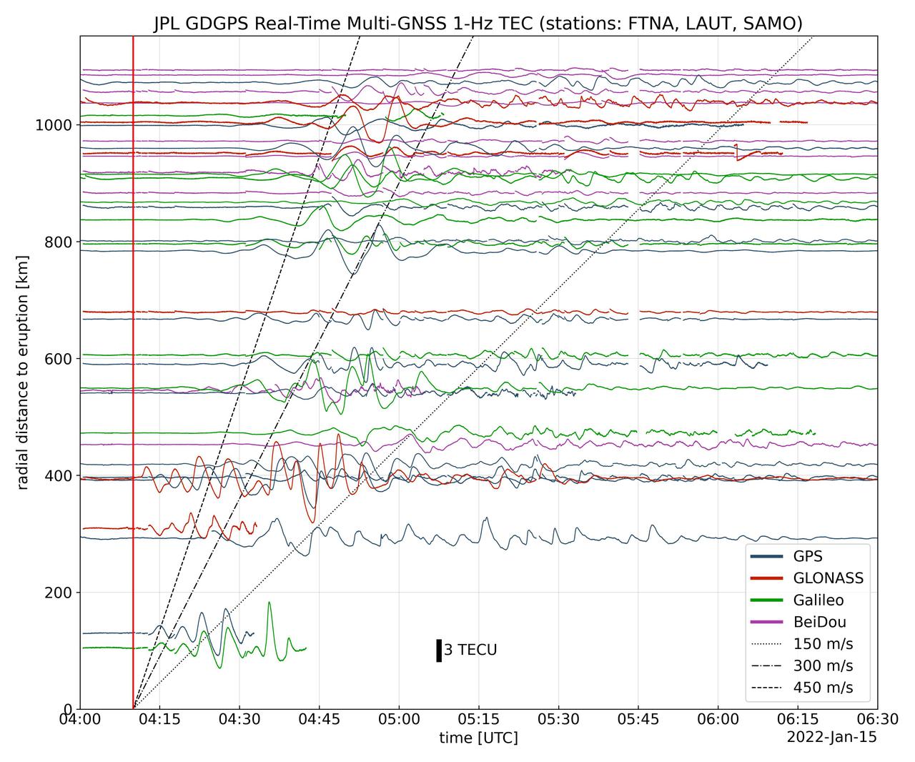
Real-time data collected by the Global Differential Global Positioning System network, operated by NASA's Jet Propulsion Laboratory, shows the atmospheric signature of the Hunga Tonga Hunga Ha'apai volcanic eruption in Tonga on Jan. 15, 2022. The data is a measure of the density of electrons (known as total electron content units, or TECU) in the ionosphere – the outermost layer of the atmosphere, which starts between 50 and 56 miles (80 to 90 kilometers) above Earth's surface. Navigation radio signals, like those received by location sensors on smartphones, are broadcast by global navigation satellite systems (GNSS) and experience delays when passing through the ionosphere. The extent of the delay depends on the density of electrons within the path of the GNSS signal in this atmospheric layer. When an explosive event such as a volcanic eruption or large earthquake injects energy into the atmosphere, the pressure waves from that event change the electron density in the ionosphere. These perturbations show up as tiny changes to the delays that GNSS radio signals usually experience as they pass through the atmosphere. The vertical red line in the data plot indicates the time of the eruption. The horizontal squiggles show electron density profiles picked up in the signals of four GNSS constellations, or groups of satellites: GPS, GLONASS, Galileo, and BeiDou. The slanted dashed and dotted lines indicate the velocity of waves. https://photojournal.jpl.nasa.gov/catalog/PIA24905
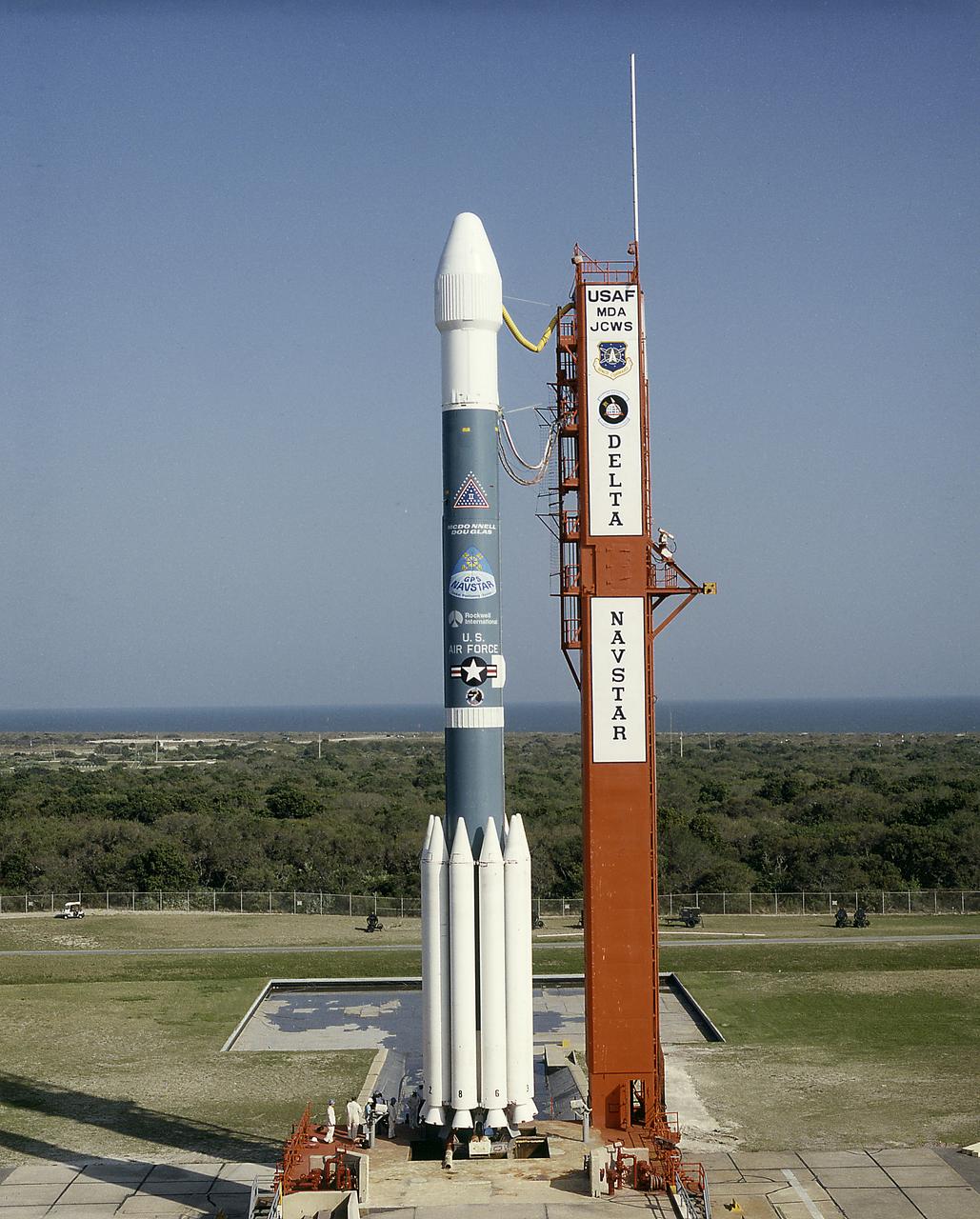
The Air Force Delta II vehicle sits poised on Complex 17A at the Cape Canaveral Air Station, ready to carry the 19th NAVSTAR Global Positioning System Satellite into orbit. A secondary NASA experiment, the Small Expendable Deployer System (SEDS), will also be deployed.
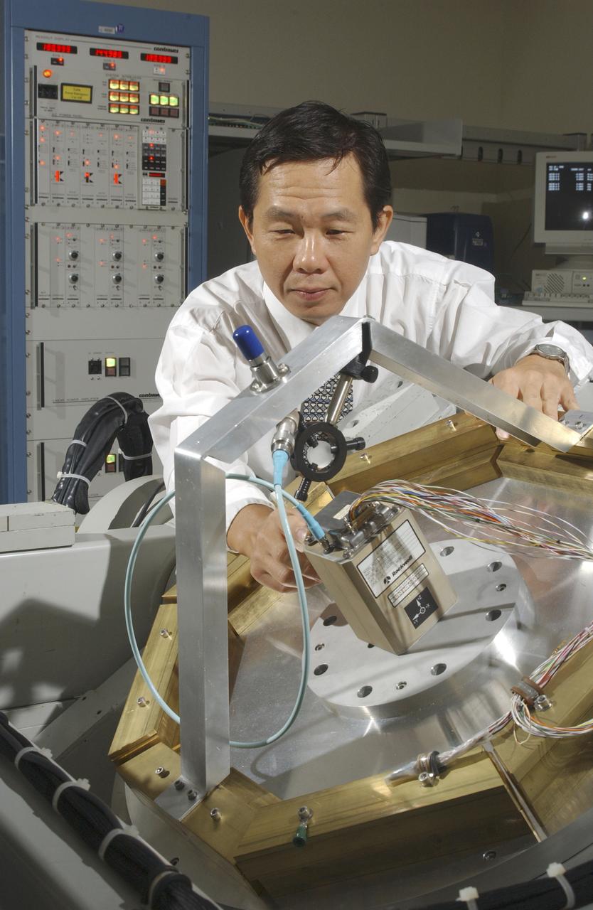
An array of components in a laboratory at NASA's Marshall Space Flight Center (MSFC) is being tested by the Flight Mechanics Office to develop an integrated navigation system for the second generation reusable launch vehicle. The laboratory is testing Global Positioning System (GPS) components, a satellite-based location and navigation system, and Inertial Navigation System (INS) components, sensors on a vehicle that determine angular velocity and linear acceleration at various points. The GPS and INS components work together to provide a space vehicle with guidance and navigation, like the push of the OnStar button in your car assists you with directions to a specific address. The integration will enable the vehicle operating system to track where the vehicle is in space and define its trajectory. The use of INS components for navigation is not new to space technology. The Space Shuttle currently uses them. However, the Space Launch Initiative is expanding the technology to integrate GPS and INS components to allow the vehicle to better define its position and more accurately determine vehicle acceleration and velocity. This advanced technology will lower operational costs and enhance the safety of reusable launch vehicles by providing a more comprehensive navigation system with greater capabilities. In this photograph, Dr. Jason Chuang of MSFC inspects an INS component in the laboratory.
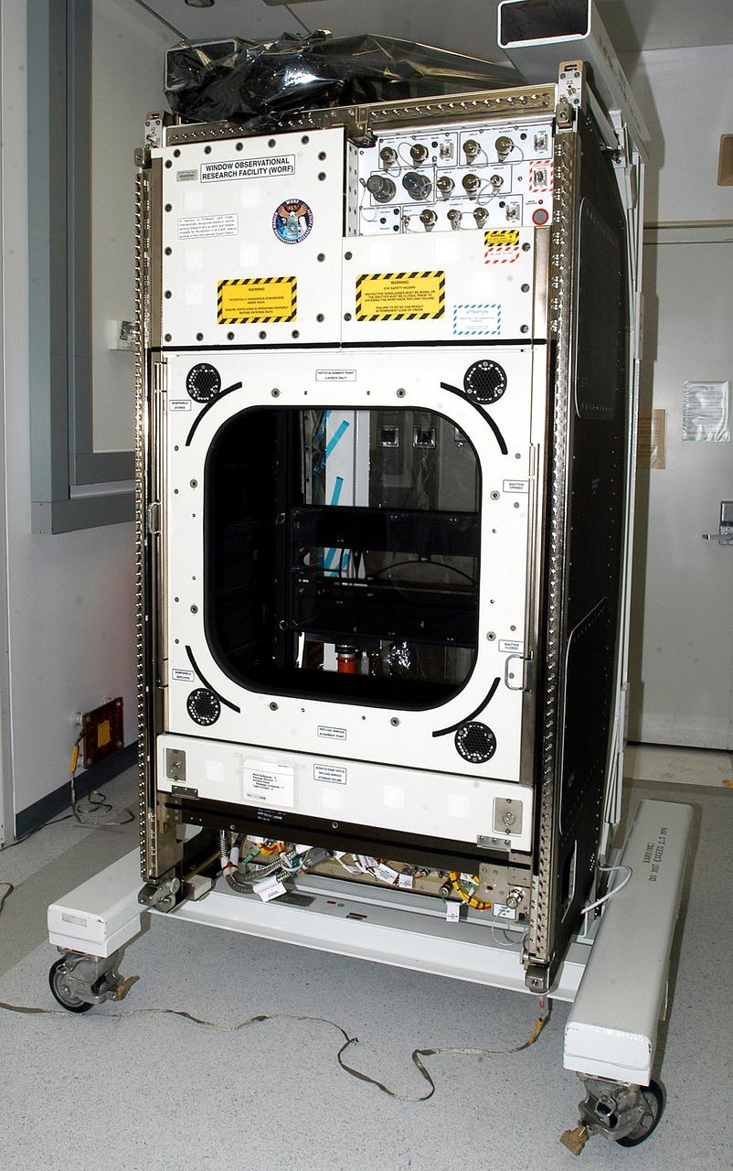
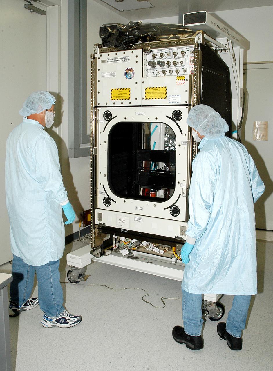
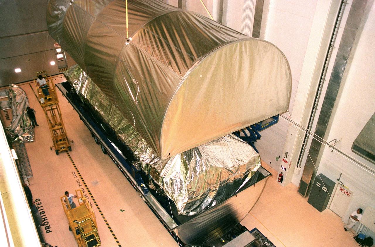
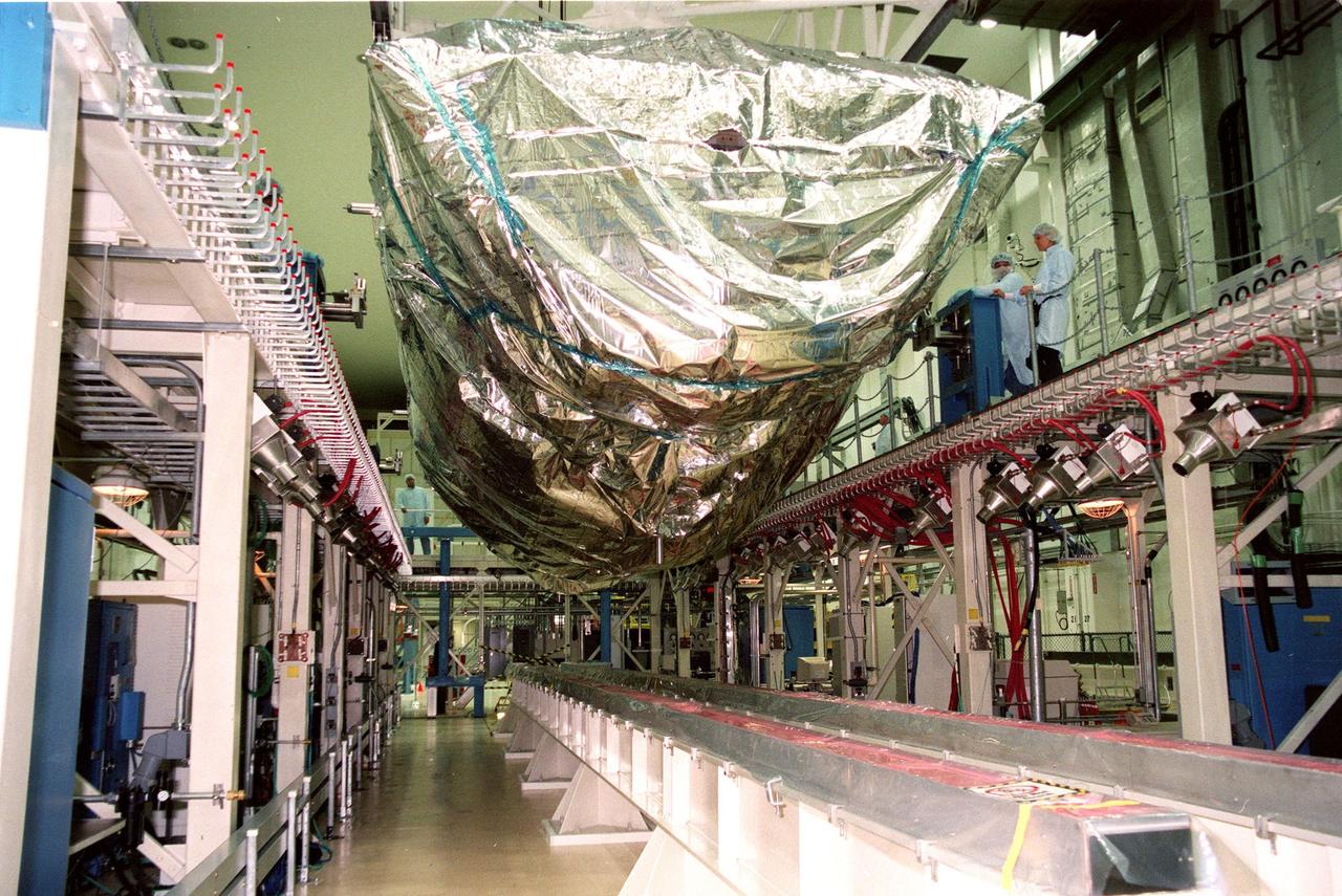
KENNEDY SPACE CENTER, FLA. - The Window Observational Research Facility (WORF), seen in the Space Station Processing Facility, was designed and built by the Boeing Co. at NASA’s Marshall Space Flight Center in Huntsville, Ala. WORF will be delivered to the International Space Station and placed in the rack position in front of the Destiny lab window, providing locations for attaching cameras, multi-spectral scanners and other instruments. WORF will support a variety of scientific and commercial experiments in areas of Earth systems and processes, global ecological changes in Earth’s biosphere, lithosphere, hydrosphere and climate system, Earth resources, natural hazards, and education. After installation, it will become a permanent focal point for Earth Science research aboard the space station.

Two F/A-18B aircraft involved in the AFF program return to base in close formation with the autonomous function disengaged.
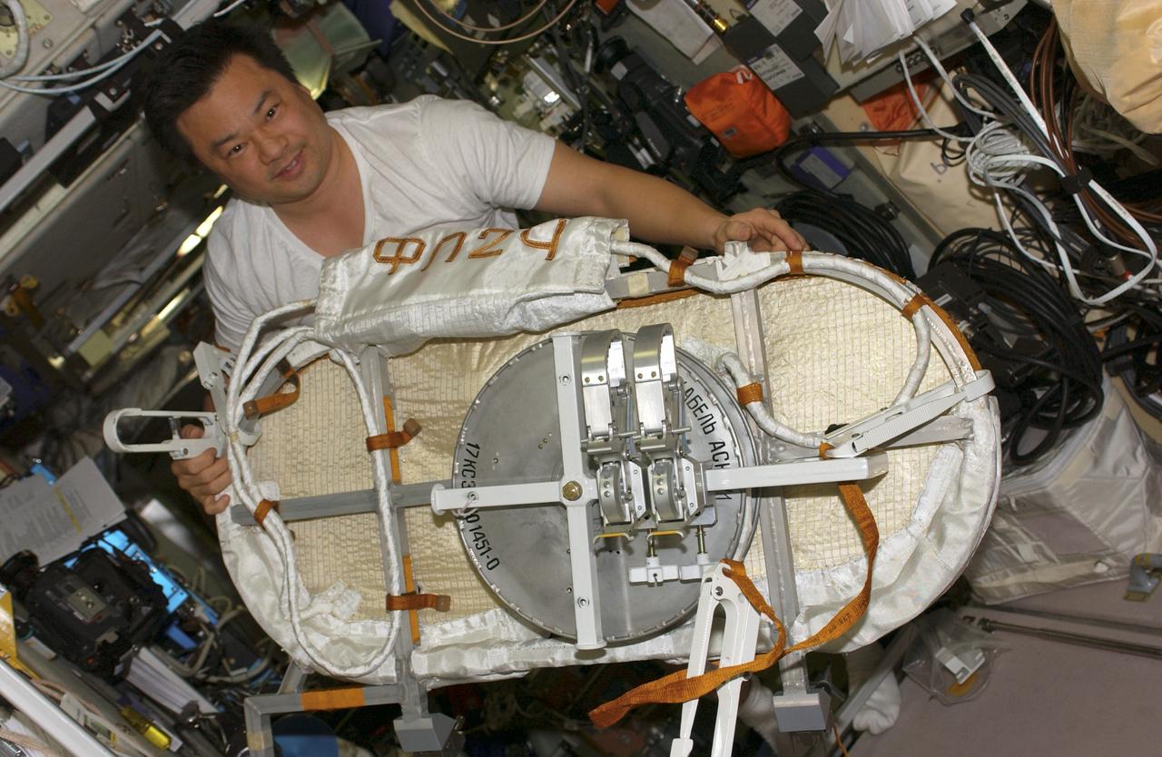
ISS010-E-20762 (21 March 2005) --- Astronaut Leroy Chiao, Expedition 10 commander and NASA ISS science officer, works with a Global Positioning System (GPS) Unit in the Zvezda Service Module of the International Space Station (ISS).
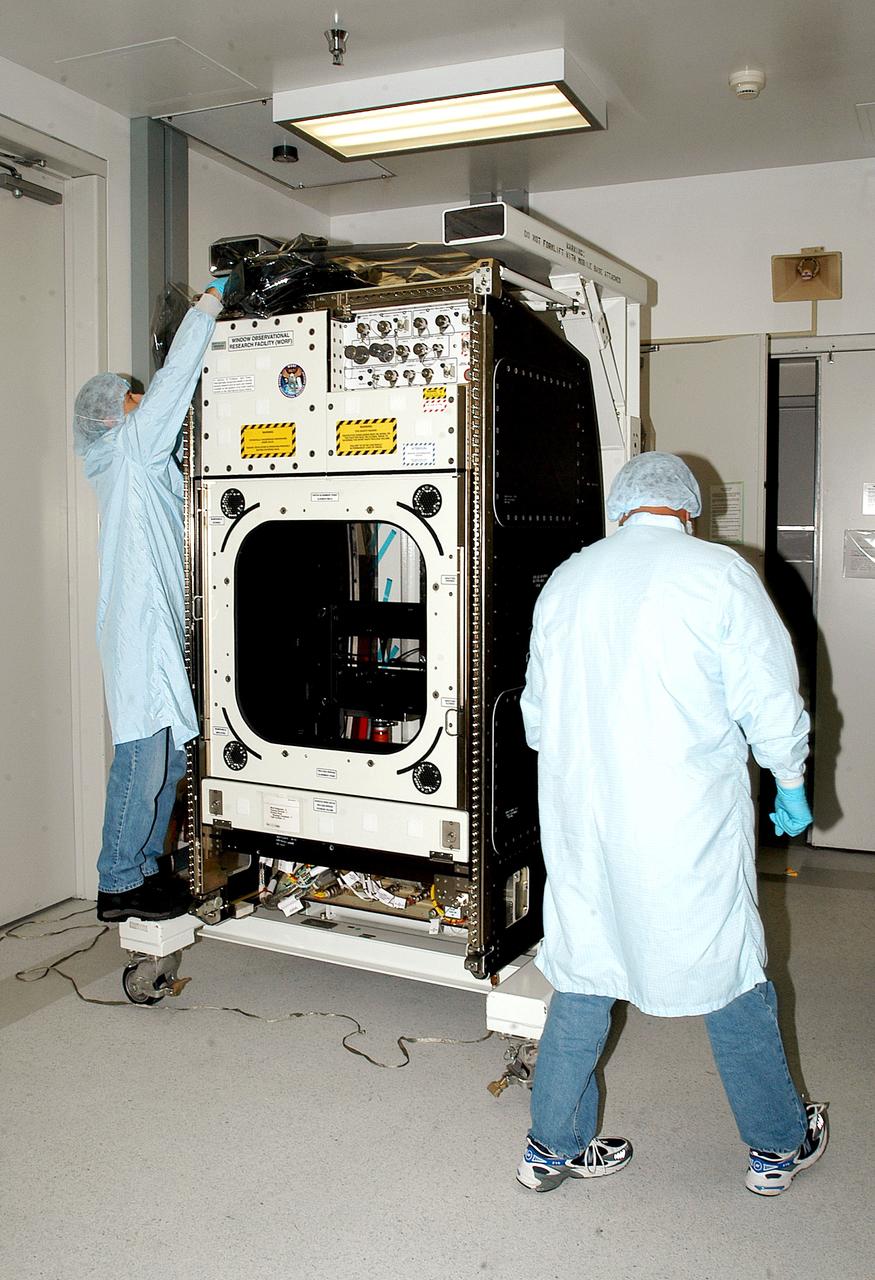
KENNEDY SPACE CENTER, FLA. - Workers in the Space Station Processing Facility check out the Window Observational Research Facility (WORF), designed and built by the Boeing Co. at NASA’s Marshall Space Flight Center in Huntsville, Ala. WORF will be delivered to the International Space Station and placed in the rack position in front of the Destiny lab window, providing locations for attaching cameras, multi-spectral scanners and other instruments. WORF will support a variety of scientific and commercial experiments in areas of Earth systems and processes, global ecological changes in Earth’s biosphere, lithosphere, hydrosphere and climate system, Earth resources, natural hazards, and education. After installation, it will become a permanent focal point for Earth Science research aboard the space station.
KENNEDY SPACE CENTER, FLA. - Workers in the Space Station Processing Facility check out the Window Observational Research Facility (WORF), designed and built by the Boeing Co. at NASA’s Marshall Space Flight Center in Huntsville, Ala. WORF will be delivered to the International Space Station and placed in the rack position in front of the Destiny lab window, providing locations for attaching cameras, multi-spectral scanners and other instruments. WORF will support a variety of scientific and commercial experiments in areas of Earth systems and processes, global ecological changes in Earth’s biosphere, lithosphere, hydrosphere and climate system, Earth resources, natural hazards, and education. After installation, it will become a permanent focal point for Earth Science research aboard the space station.

Small Expendable Deployer System (SEDS) is a tethered date collecting satellite and is intended to demonstrate a versatile and economical way of delivering smaller payloads to higher orbits or downward toward Earth's atmosphere. 19th Navstar Global Positioning System Satellite mission joined with previously launched satellites used for navigational purposes and geodite studies. These satellites are used commercially as well as by the military.
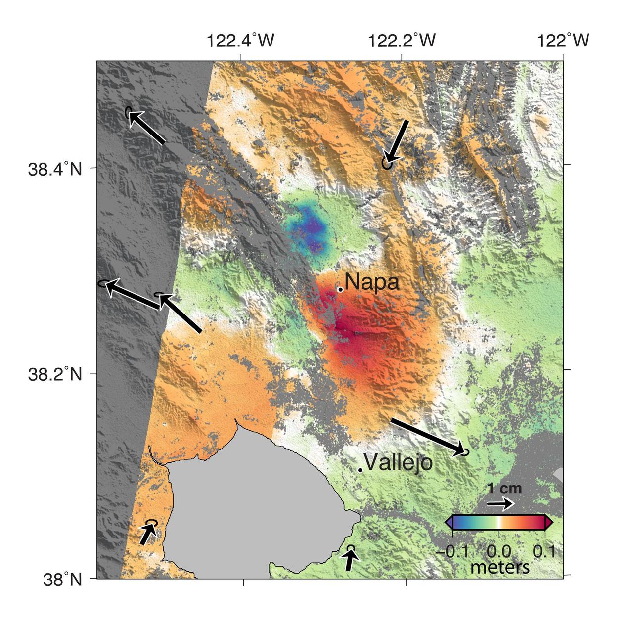
A magnitude 6.0 earthquake struck southern Napa county northeast of San Francisco, California, on Aug. 24, 2014. NASA satellite data reveal ground defomation.
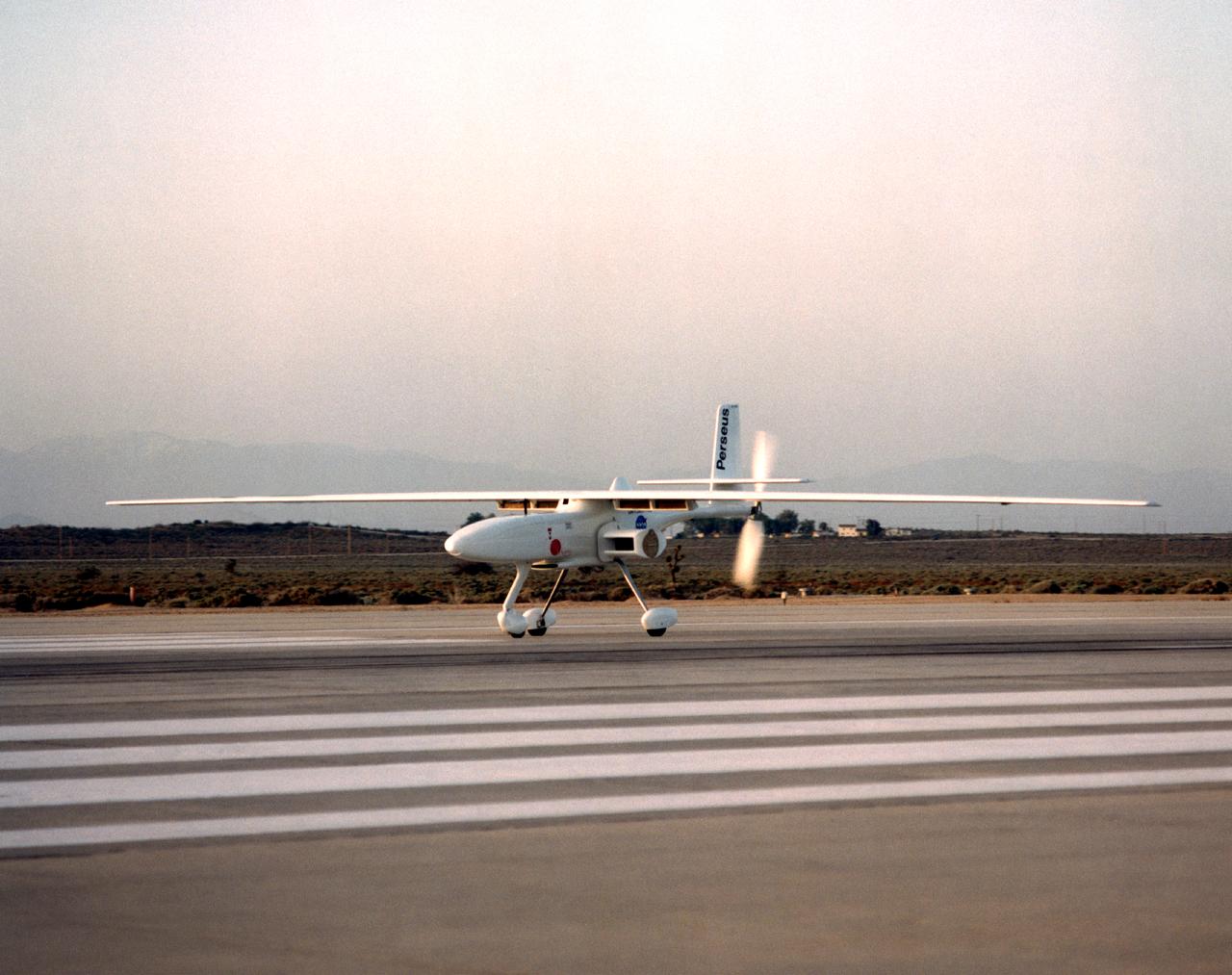
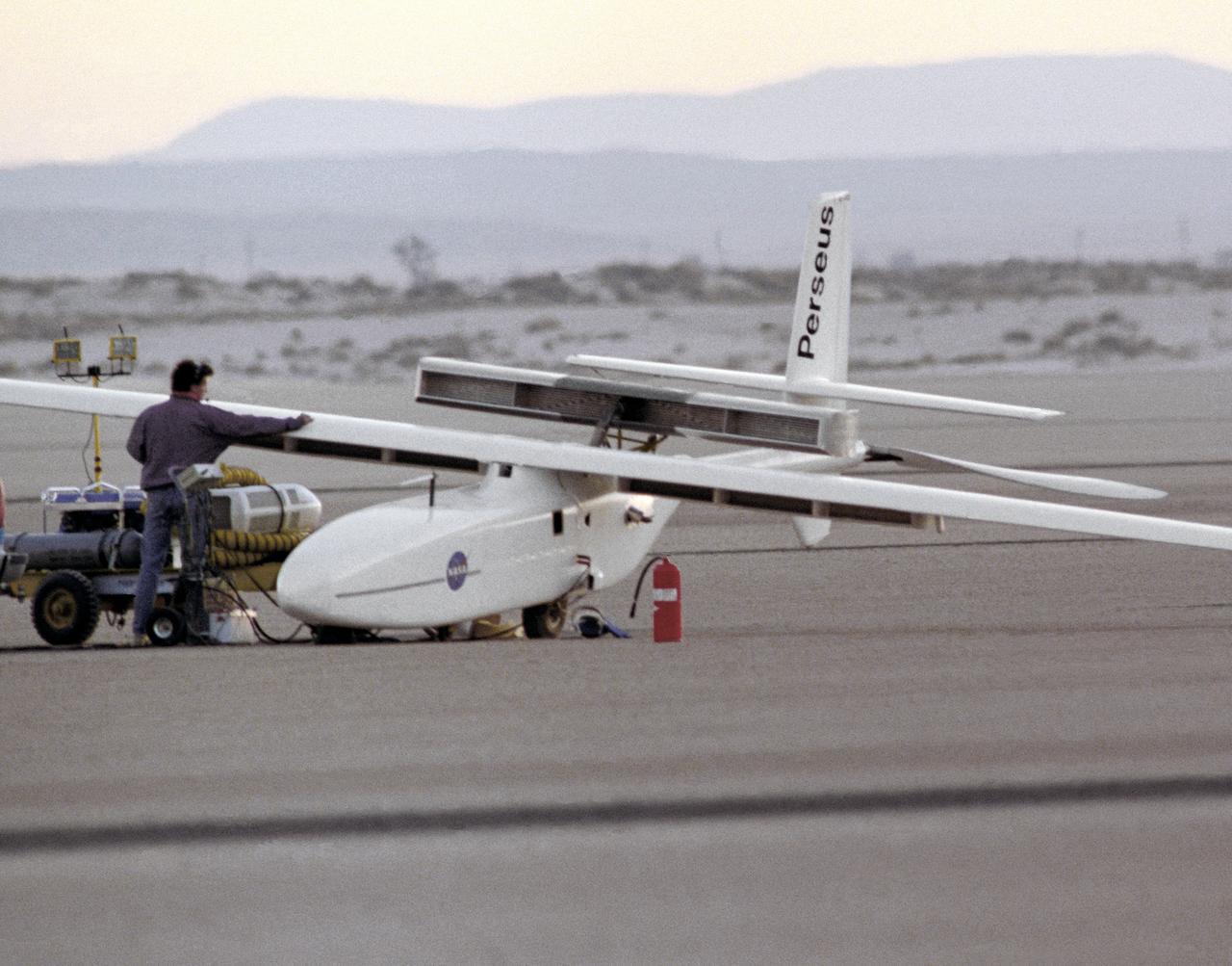
The Perseus B remotely piloted aircraft taxis on the runway at Edwards Air Force Base, California, before a series of development flights at NASA's Dryden flight Research Center. The Perseus B is the latest of three versions of the Perseus design developed by Aurora Flight Sciences under NASA's Environmental Research Aircraft and Sensor Technology (ERAST) program.
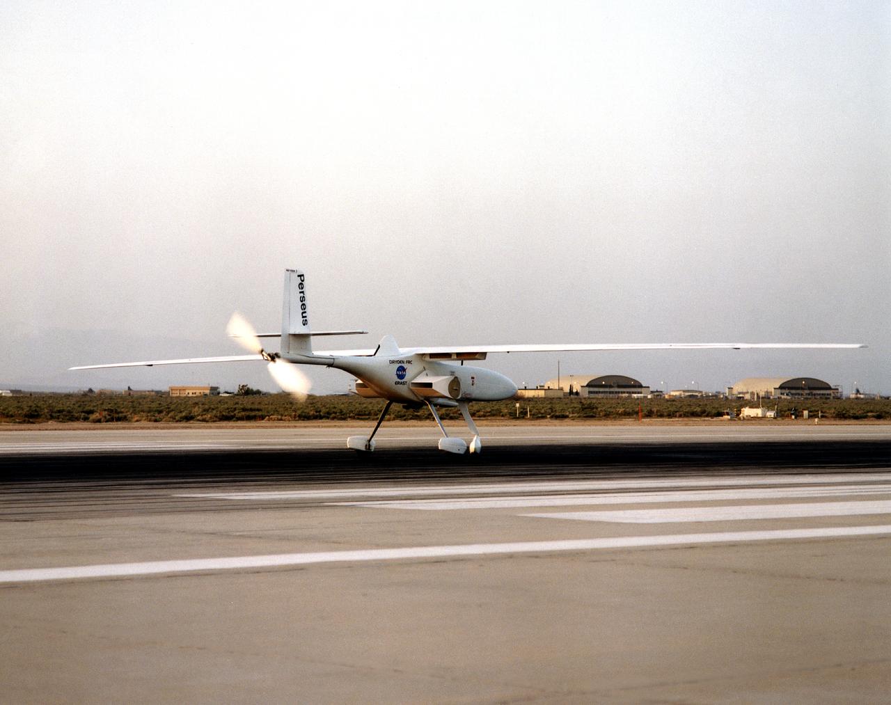
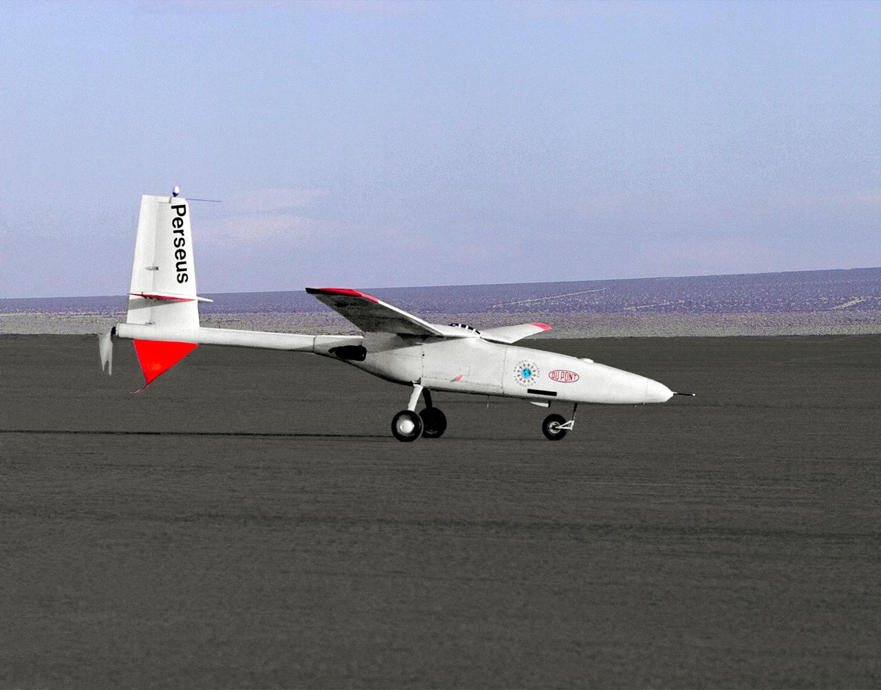
The Perseus B remotely piloted aircraft on the runway at Edwards Air Force Base, California at the conclusion of a development flight at NASA's Dryden flight Research Center. The Perseus B is the latest of three versions of the Perseus design developed by Aurora Flight Sciences under NASA's Environmental Research Aircraft and Sensor Technology (ERAST) program.
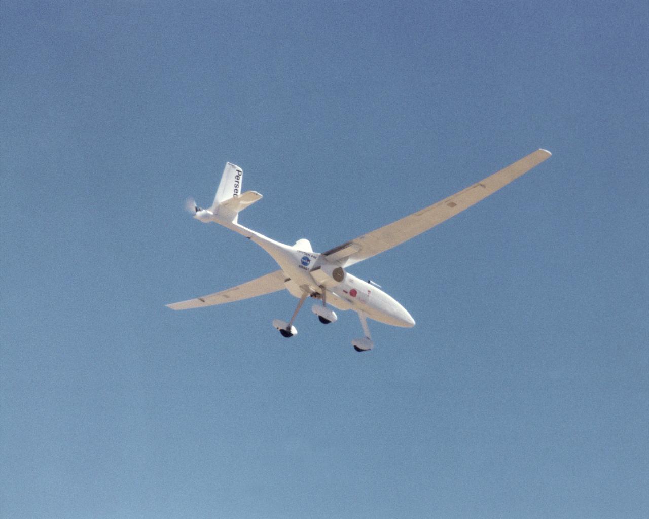
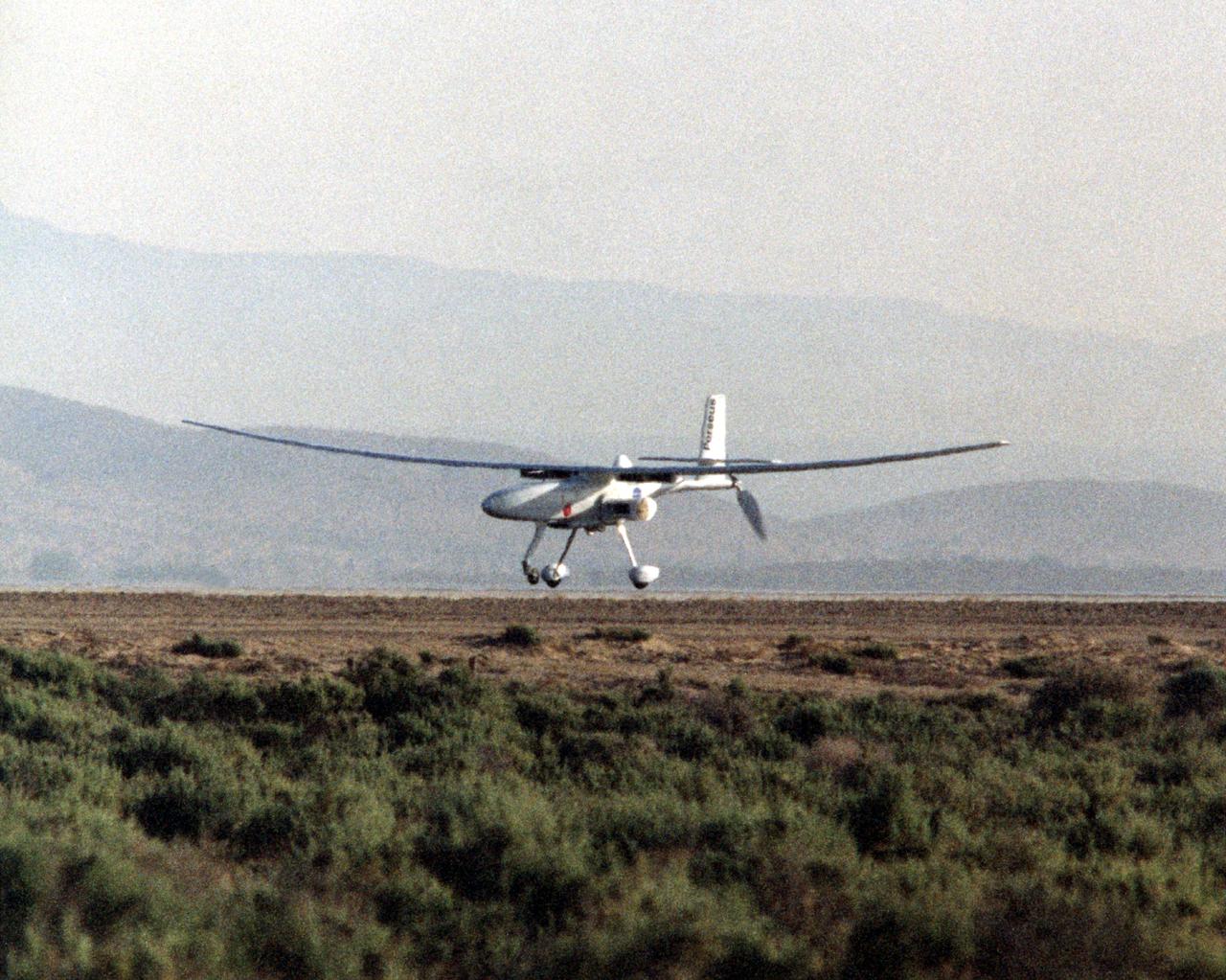
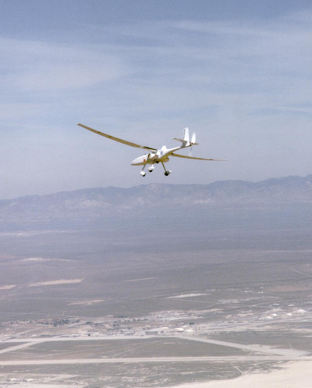
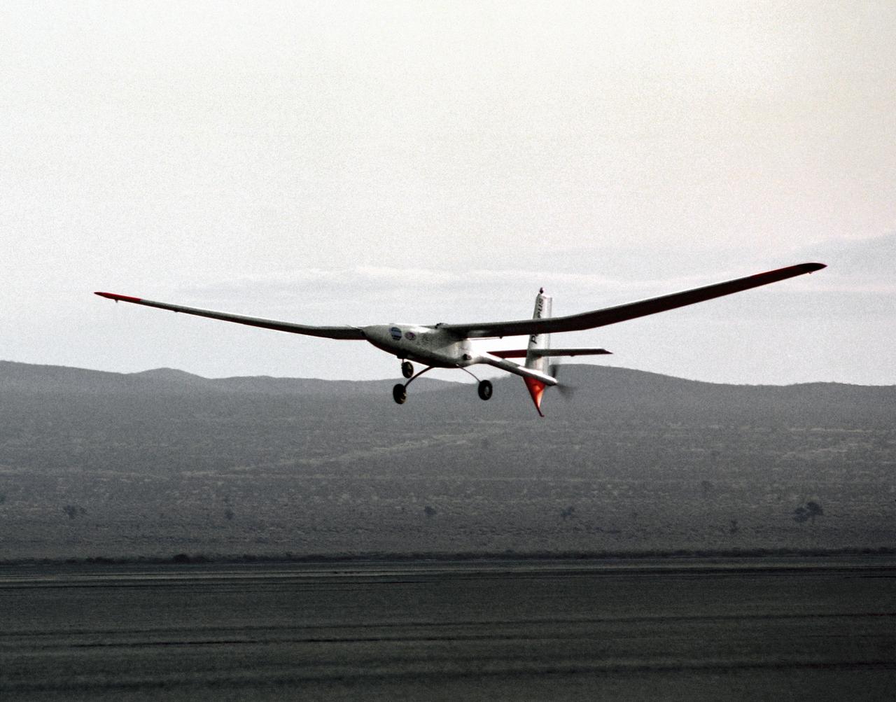
A long, slender wing and a pusher propeller at the rear characterize the Perseus B remotely piloted research aircraft, seen here during a test flight in June 1998.
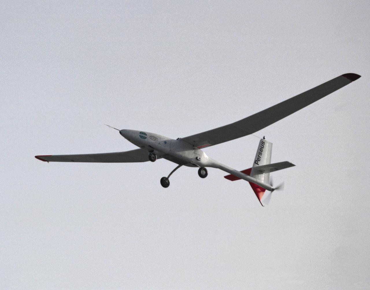
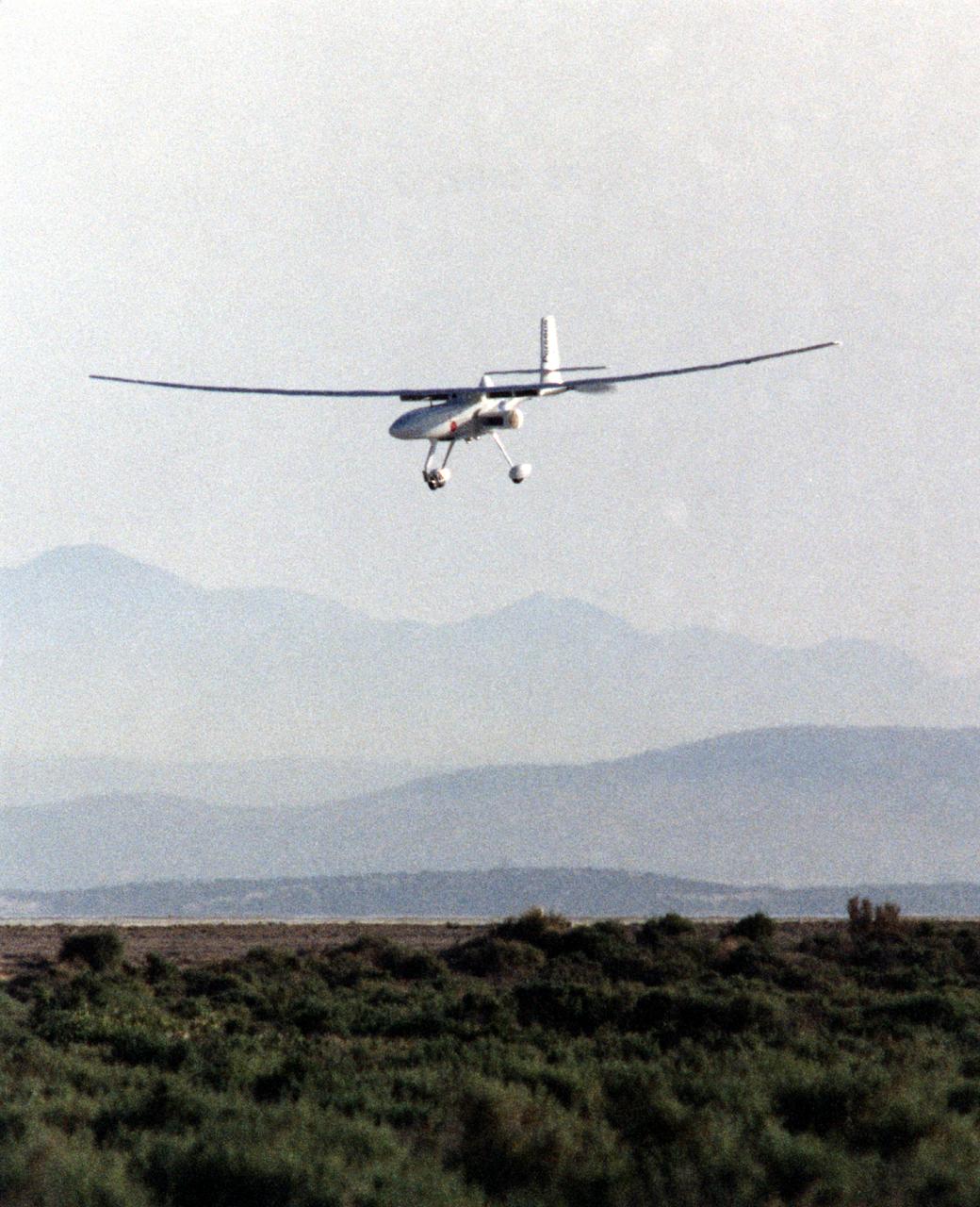
The Perseus proof-of-concept vehicle in flight at the Dryden Flight Research Center, Edwards, California in 1991. Perseus is one of several remotely-piloted aircraft designed for high-altitude, long-endurance scientific sampling missions being evaluated under the ERAST program.
The Perseus A, a remotely-piloted, high-altitude research vehicle, is seen just after landing on Rogers Dry Lake at the Dryden Flight Research Center, Edwards, California. The Perseus A had a unique method of takeoff and landing. To make the aircraft as aerodynamic and lightweight as possible, designers gave it only two very small centerline wheels for landing. These wheels were very close to the fuselage, and therefore produced very little drag. However, since the fuselage sat so close to the ground, it was necessary to keep the large propeller at the rear of the aircraft locked in a horizontal position during takeoff. The aircraft was towed to about 700 feet in the air, where the engine was started and the aircraft began flying under its own power.
The Perseus B remotely piloted aircraft nears touchdown at Edwards Air Force Base, Calif. at the conclusion of a development flight at NASA's Dryden Flight Research Center. The Perseus B is the latest of three versions of the Perseus design developed by Aurora Flight Sciences under NASA's Environmental Research Aircraft and Sensor Technology (ERAST) program.
A long, slender wing and a pusher propeller at the rear characterize the Perseus B remotely-piloted research aircraft, seen here during a test flight in April1998.
The Perseus proof-of-concept vehicle is seen here as it taxis on Rogers Dry Lake, adjacent the Dryden Flight Research Center, Edwards, California.
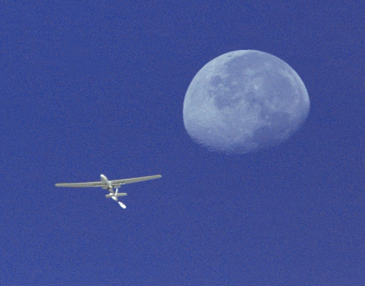
The Perseus A, a remotely-piloted, high-altitude research aircraft, is seen here framed against the moon and sky during a research mission at the Dryden Flight Research Center, Edwards, California in August 1994.
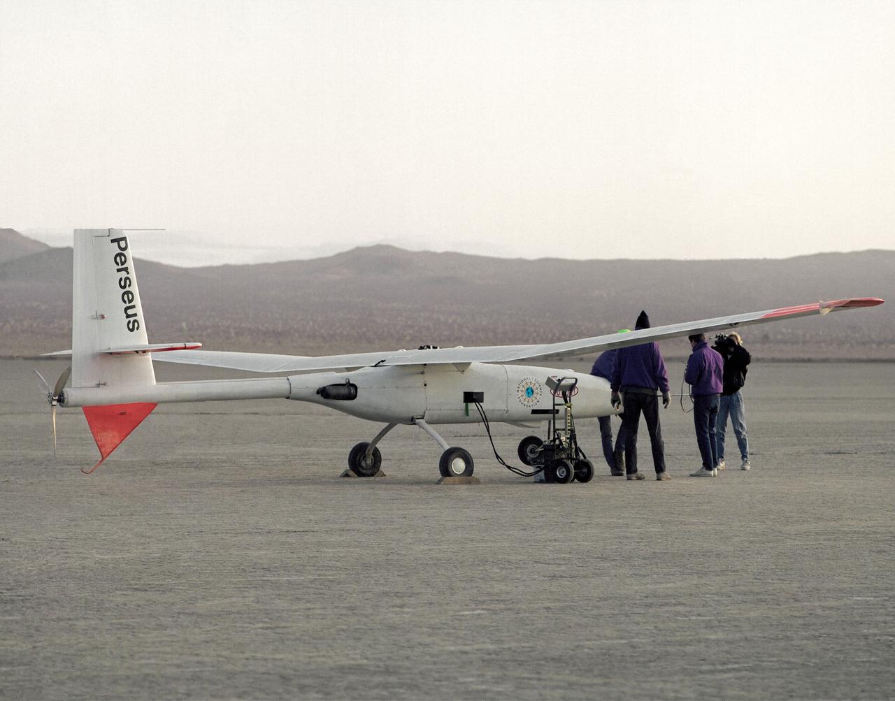
Crew members check out the Perseus proof-of-concept vehicle on Rogers Dry Lake, adjacent to the Dryden Flight Research Center, Edwards, California, after a test flight in 1991.
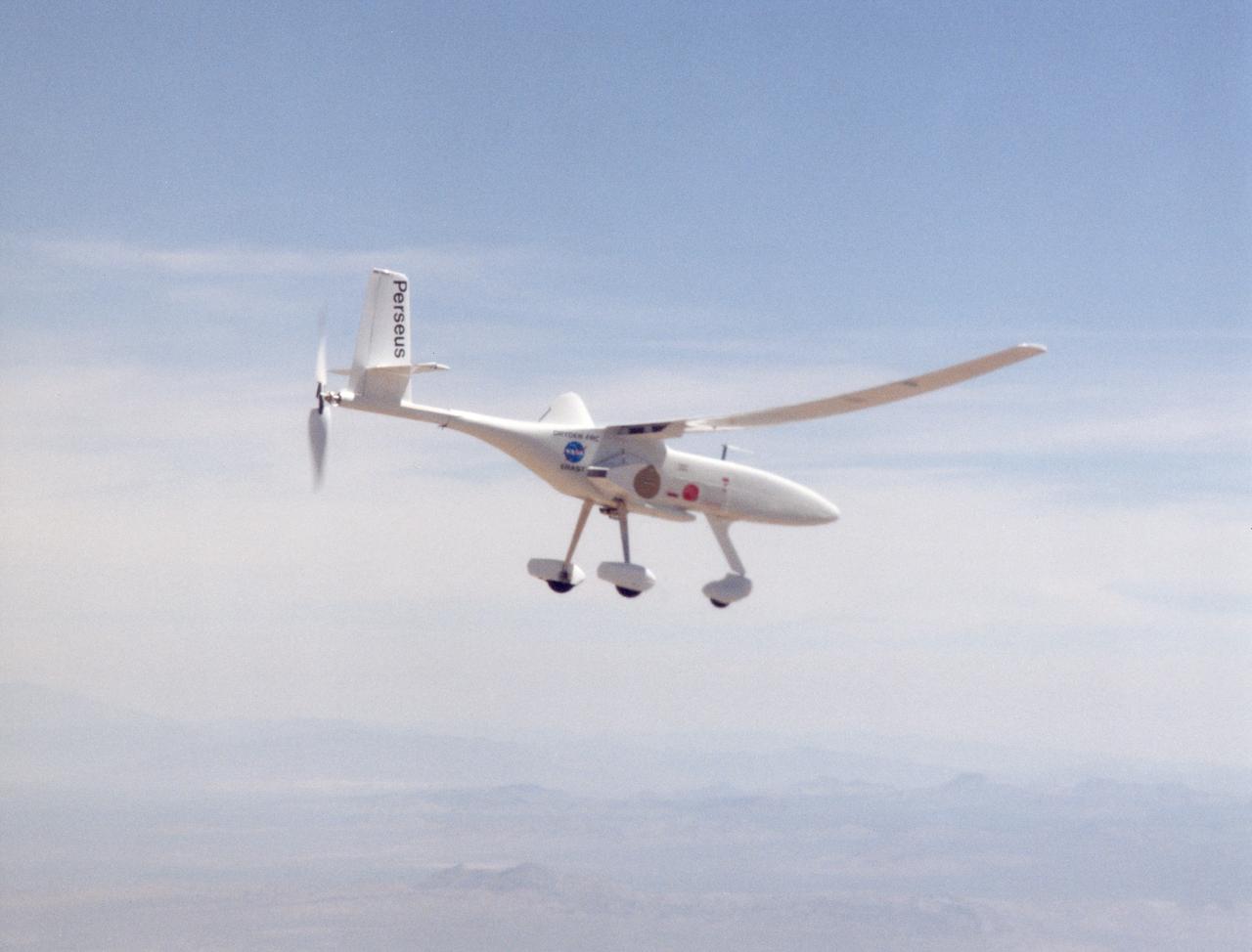
A long, slender wing and a pusher propeller at the rear characterize the Perseus B remotely piloted research aircraft, seen here during a test flight in June 1998.
The Perseus B remotely piloted aircraft approaches the runway at Edwards Air Force Base, Calif. at the conclusion of a development flight at NASA's Dryden flight Research Center in April 1998. The Perseus B is the latest of three versions of the Perseus design developed by Aurora Flight Sciences under NASA's Environmental Research Aircraft and Sensor Technology (ERAST) program.
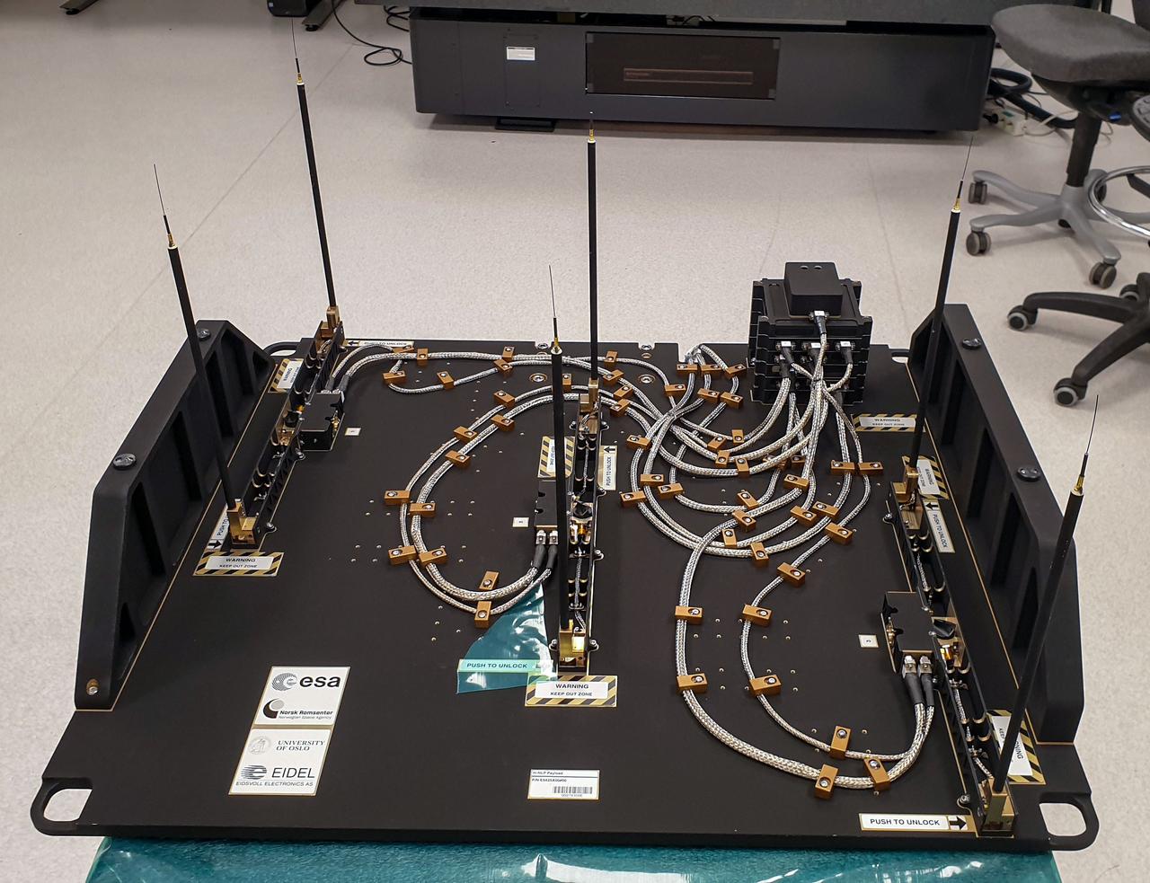
jsc2023e046372 (9/30/2022) --- The Multi-Needle Langmuir Probe (m-NLP) is shown from the ram facing side with booms in deployed position. The m-NLP measures plasma density in the ionosphere, where Earth's atmosphere meets the beginning of space. Researchers aim to study electrically charged particles and increase their understanding of how particle phenomena affect radio communications and global navigation satellite system (GNSS) signals. Image courtesy of the University of Oslo, Espen Trondsen.
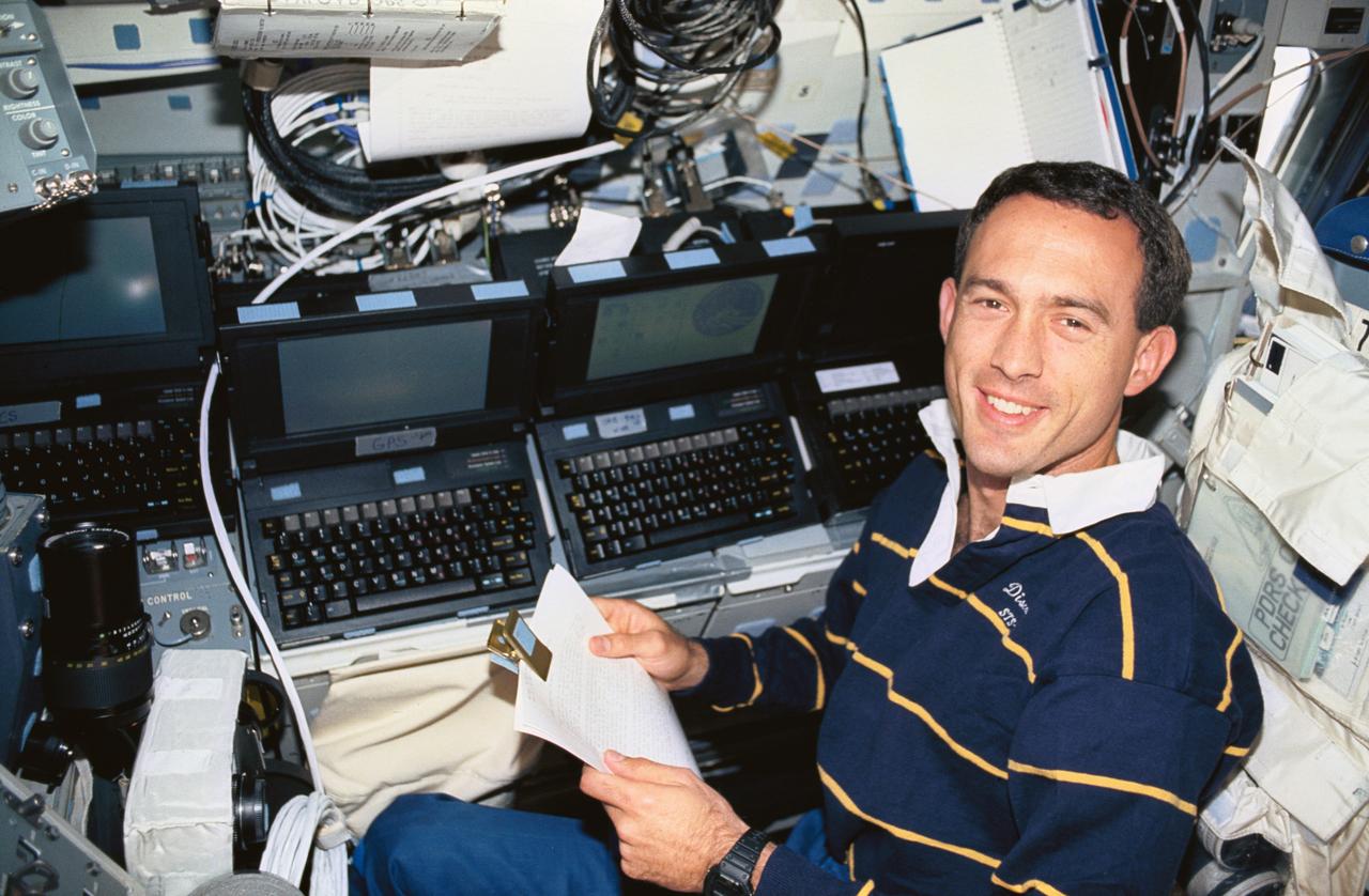
STS051-16-028 (12-22 Sept 1993) --- On Discovery's middeck, astronaut James H. Newman, mission specialist, works with an array of computers, including one devoted to Global Positioning System (GPS) operations, a general portable onboard computer displaying a tracking map, a portable audio data modem and another payload and general support computer. Newman was joined by four other NASA astronauts for almost ten full days in space.
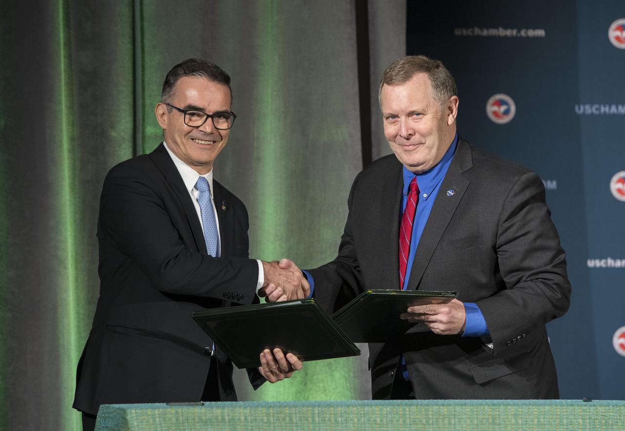
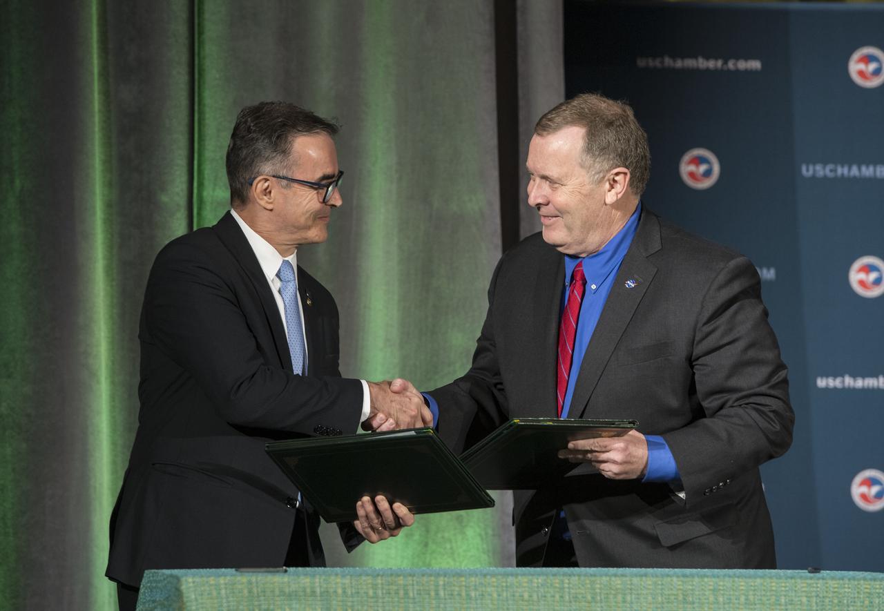
NASA Deputy Administrator James Morhard, right, shakes hands with President of the Brazilian Space Agency (AEB) Carlos Augusto Teixeira de Moura, left, after signing an agreement for cooperation on the Scintillation Prediction Observations Research Task (SPORT), an upcoming NASA-AEB heliophysics CubeSat partnership, Monday, March 18, 2019, at the U.S. Chamber of Commerce in Washington. The SPORT CubeSat will investigate two ionospheric phenomena, equatorial plasma bubbles and scintillation, that disrupt radio communication systems, satellite technologies, and Global Positioning System (GPS) signals. SPORT is currently projected to launch in the 2020 timeframe. Photo Credit: (NASA/ Aubrey Gemignani)

NASA Deputy Administrator James Morhard, left, speaks with H.E. President Jair Bolsonaro of Brazil, just before signing an agreement with President of the Brazilian Space Agency (AEB), Carlos Augusto Teixeira de Moura, for cooperation on the Scintillation Prediction Observations Research Task (SPORT), an upcoming NASA-AEB heliophysics CubeSat partnership, Monday, March 18, 2019, at the U.S. Chamber of Commerce in Washington. The SPORT CubeSat will investigate two ionospheric phenomena, equatorial plasma bubbles and scintillation, that disrupt radio communication systems, satellite technologies, and Global Positioning System (GPS) signals. SPORT is currently projected to launch in the 2020 timeframe. Photo Credit: (NASA/ Aubrey Gemignani)
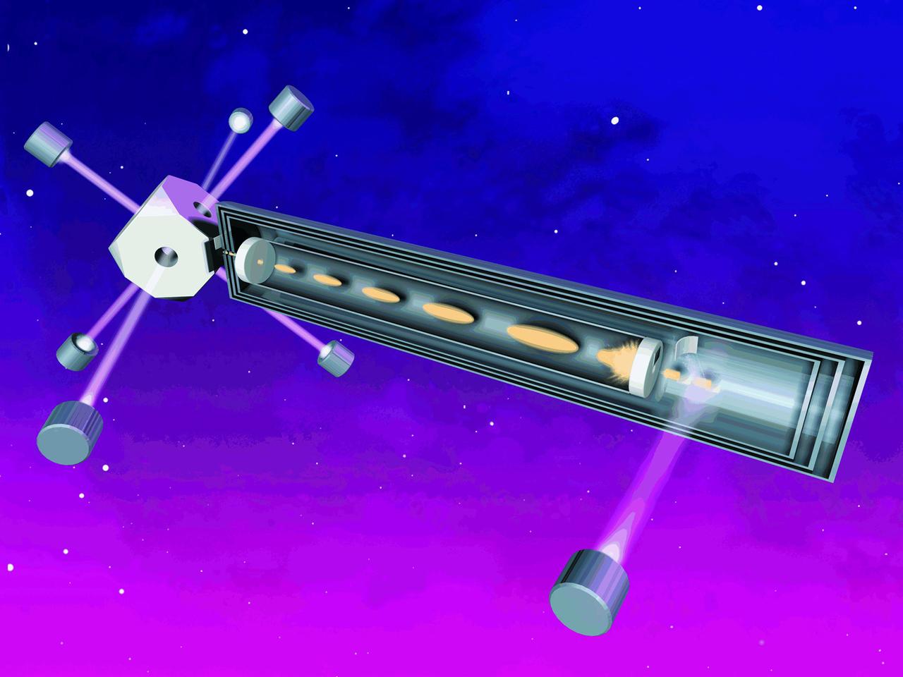
An artist's concept of the Primary Atomic Clock Reference System (PARCS) plarned to fly on the International Space Station (ISS). PARCS will make even more accurate atomic time available to everyone, from physicists testing Einstein's Theory of Relativity, to hikers using the Global Positioning System to find their way. In ground-based atomic clocks, lasers are used to cool and nearly stop atoms of cesium whose vibrations are used as the time base. The microgravity of space will allow the atoms to be suspended in the clock rather than circulated in an atomic fountain, as required on Earth. PARCS is being developed by the Jet Propulsion Laboratory with principal investigators at the National Institutes of Standards and Technology and the University of Colorado, Boulder. See also No. 0103191
NASA Deputy Administrator James Morhard, right, shakes hands with President of the Brazilian Space Agency (AEB) Carlos Augusto Teixeira de Moura, left, after signing an agreement for cooperation on the Scintillation Prediction Observations Research Task (SPORT), an upcoming NASA-AEB heliophysics CubeSat partnership, Monday, March 18, 2019, at the U.S. Chamber of Commerce in Washington. The SPORT CubeSat will investigate two ionospheric phenomena, equatorial plasma bubbles and scintillation, that disrupt radio communication systems, satellite technologies, and Global Positioning System (GPS) signals. SPORT is currently projected to launch in the 2020 timeframe. Photo Credit: (NASA/ Aubrey Gemignani)
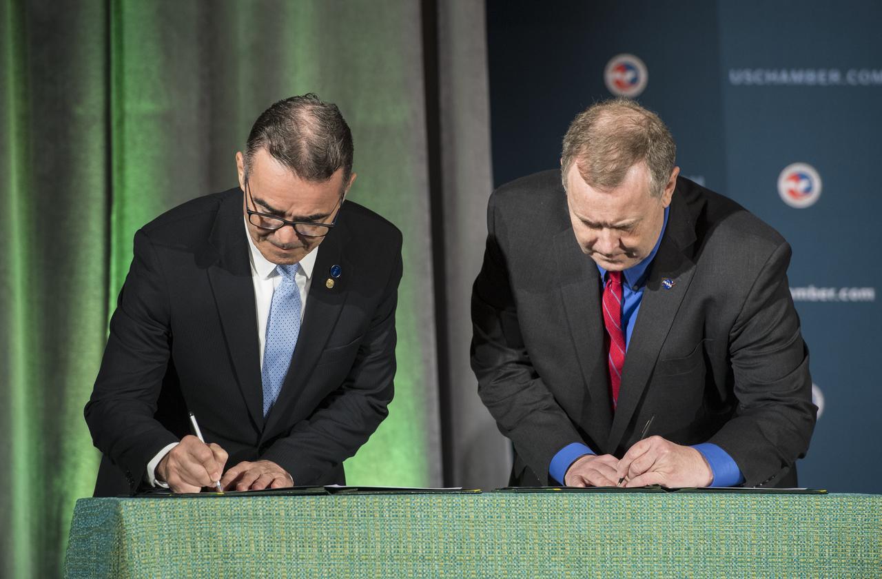
NASA Deputy Administrator James Morhard, right, and President of the Brazilian Space Agency (AEB) Carlos Augusto Teixeira de Moura, left, sign an agreement for cooperation on the Scintillation Prediction Observations Research Task (SPORT), an upcoming NASA-AEB heliophysics CubeSat partnership, Monday, March 18, 2019, at the U.S. Chamber of Commerce in Washington. The SPORT CubeSat will investigate two ionospheric phenomena, equatorial plasma bubbles and scintillation, that disrupt radio communication systems, satellite technologies, and Global Positioning System (GPS) signals. SPORT is currently projected to launch in the 2020 timeframe. Photo Credit: (NASA/ Aubrey Gemignani)

NASA Deputy Administrator James Morhard, right, shakes hands with President of the Brazilian Space Agency (AEB) Carlos Augusto Teixeira de Moura, left, after signing an agreement for cooperation on the Scintillation Prediction Observations Research Task (SPORT), an upcoming NASA-AEB heliophysics CubeSat partnership, Monday, March 18, 2019, at the U.S. Chamber of Commerce in Washington. The SPORT CubeSat will investigate two ionospheric phenomena, equatorial plasma bubbles and scintillation, that disrupt radio communication systems, satellite technologies, and Global Positioning System (GPS) signals. SPORT is currently projected to launch in the 2020 timeframe. Photo Credit: (NASA/ Aubrey Gemignani)
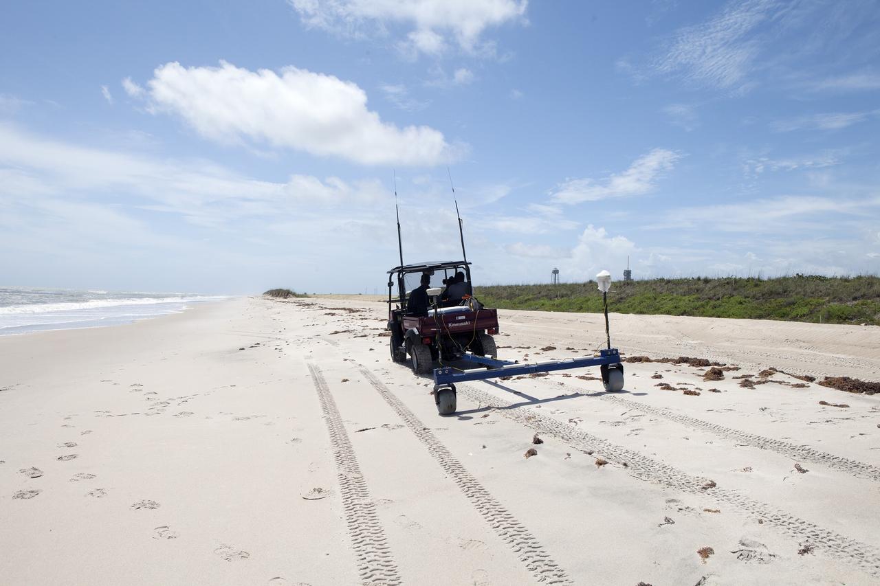
CAPE CANAVERAL, Fla. -- Rich MacKenzie, who earned a doctorate in geological sciences at the University of Florida, collects Global Positioning System survey measurements along a restored 1.2 mile stretch of shoreline near Launch Pads 39A and B. Experts from University of Florida are working with NASA scientists to better understand beach erosion. Constant pounding from tropical storms, such as Hurricane Sandy in October of 2012, other weather systems and higher than usual tides, destroyed sand dunes protecting infrastructure at the spaceport. Photo credit: NASA/Dan Casper
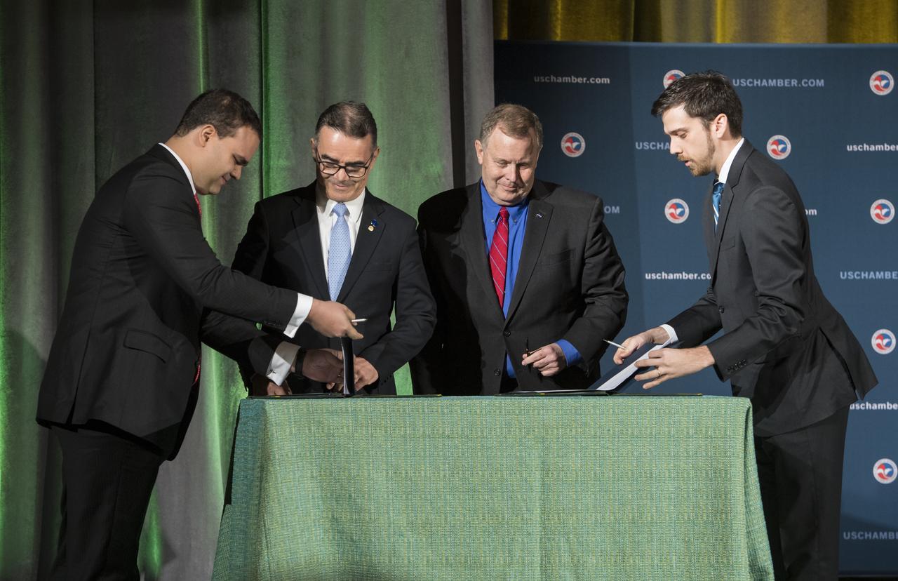
NASA Deputy Administrator James Morhard, center right, and President of the Brazilian Space Agency (AEB) Carlos Augusto Teixeira de Moura, center left, prepare to sign an agreement for cooperation on the Scintillation Prediction Observations Research Task (SPORT), an upcoming NASA-AEB heliophysics CubeSat partnership, Monday, March 18, 2019, at the U.S. Chamber of Commerce in Washington. The SPORT CubeSat will investigate two ionospheric phenomena, equatorial plasma bubbles and scintillation, that disrupt radio communication systems, satellite technologies, and Global Positioning System (GPS) signals. SPORT is currently projected to launch in the 2020 timeframe. Photo Credit: (NASA/ Aubrey Gemignani)
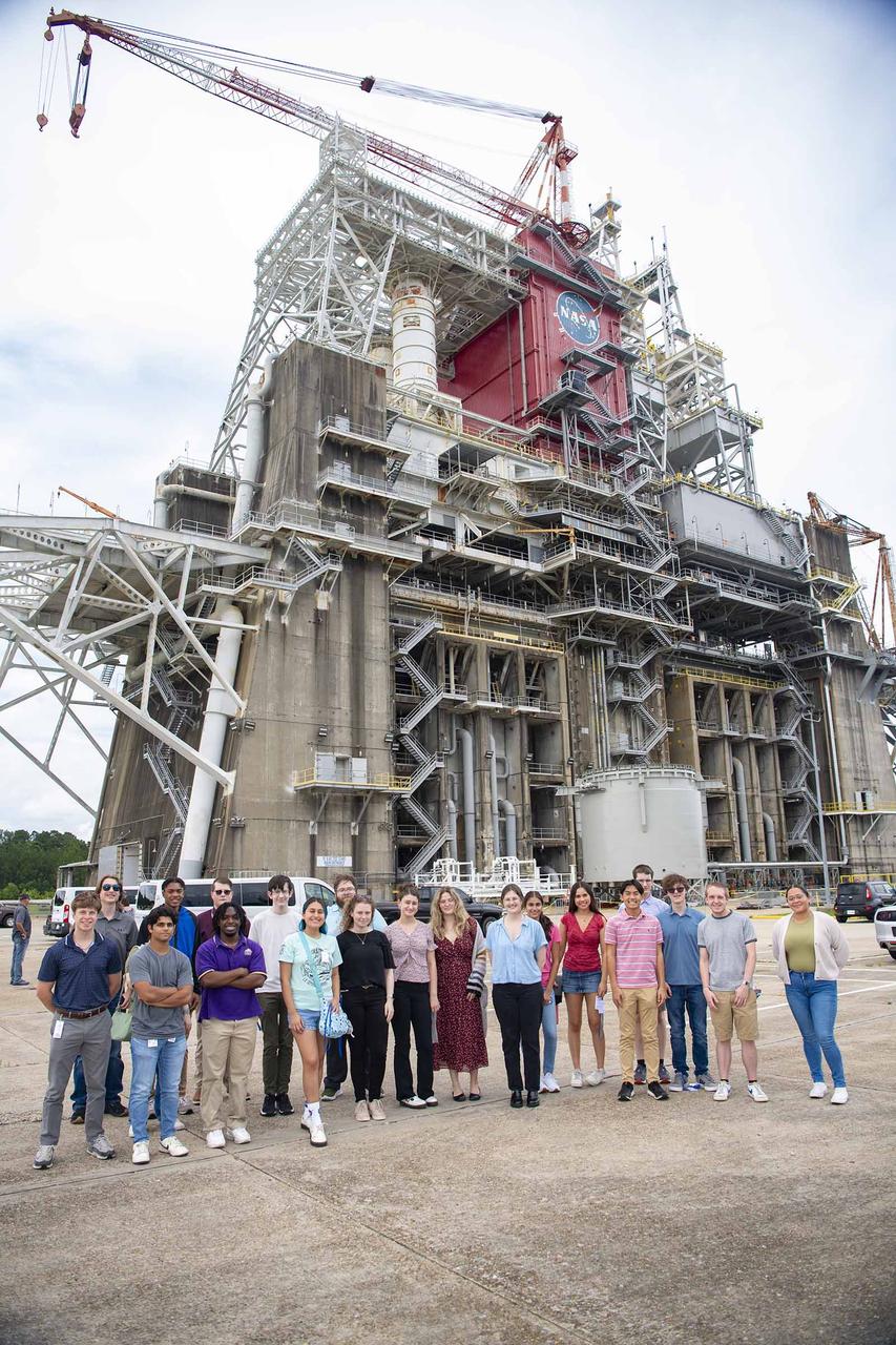
Summer interns with the U.S. Naval Research Laboratory stand in front of the Thad Cochran Test Stand (B-1/B-2) on July 10. NASA Stennis crews are preparing the B-2 side of the stand for future testing of NASA’s exploration upper stage. The more powerful second stage is expected to fly on NASA’s SLS (Space Launch System) rocket for Artemis IV. The Naval Research Laboratory interns visited the stand during an afternoon tour of NASA Stennis. The Naval Research Laboratory is a tenant of the NASA Stennis federal city, where it provides advanced scientific capabilities required to bolster the nation’s position of global naval leadership.
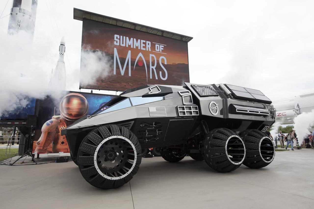
The scientifically-themed Mars rover concept vehicle operates on an electric motor, powered by solar panels and a 700-volt battery. The rover separates in the middle with the front area designed for scouting and equipped with a radio and navigation provided by the Global Positioning System. The back section serves as a full laboratory which can disconnect for autonomous research. The "Summer of Mars" promotion is designed to provide guests with a better understanding of NASA's studies of the Red Planet. The builders of the rover, Parker Brothers Concepts of Port Canaveral, Florida, incorporated input into its design from NASA subject matter experts.
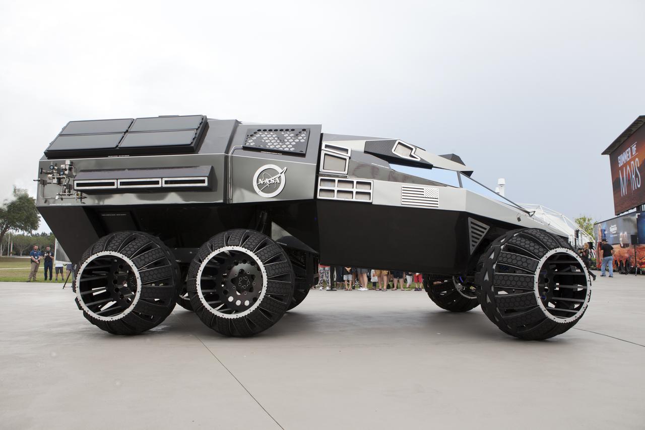
The scientifically-themed Mars rover concept vehicle operates on an electric motor, powered by solar panels and a 700-volt battery. The rover separates in the middle with the front area designed for scouting and equipped with a radio and navigation provided by the Global Positioning System. The back section serves as a full laboratory which can disconnect for autonomous research. The "Summer of Mars" promotion is designed to provide guests with a better understanding of NASA's studies of the Red Planet. The builders of the rover, Parker Brothers Concepts of Port Canaveral, Florida, incorporated input into its design from NASA subject matter experts.
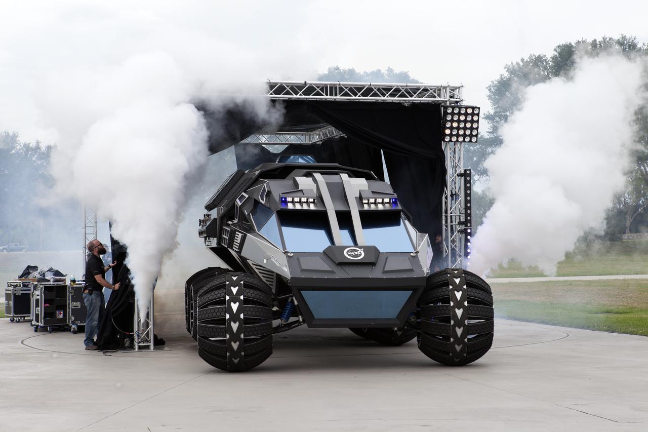
The scientifically-themed Mars rover concept vehicle operates on an electric motor, powered by solar panels and a 700-volt battery. The rover separates in the middle with the front area designed for scouting and equipped with a radio and navigation provided by the Global Positioning System. The back section serves as a full laboratory which can disconnect for autonomous research. The "Summer of Mars" promotion is designed to provide guests with a better understanding of NASA's studies of the Red Planet. The builders of the rover, Parker Brothers Concepts of Port Canaveral, Florida, incorporated input into its design from NASA subject matter experts.
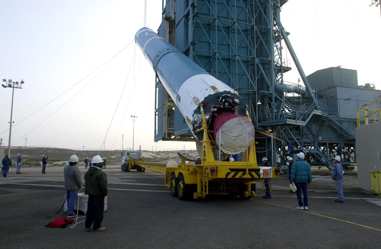
KENNEDY SPACE CENTER, FLA. - Workers at NASA's Space Launch Complex 2 (SLC-2) at Vandenberg Air Force Base, Calif., watch as the first stage of the Delta II rocket is raised to a vertical position. The rocket will carry the ICESat and CHIPSat satellites into Earth orbits. ICESat is a 661-pound satellite known as Geoscience Laser Altimeter System (GLAS) that will revolutionize our understanding of ice and its role in global climate change and how we protect and understand our home planet. It will help scientists determine if the global sea level is rising or falling. It will look at the ice sheets that blanket the Earth's poles to see if they are growing or shrinking. It will assist in developing an understanding of how changes in the Earth's atmosphere and climate effect polar ice masses and global sea level. CHIPSat, a suitcase-size 131-pound satellite, will provide invaluable information into the origin, physical processes and properties of the hot gas contained in the interstellar medium. This can provide important clues about the formation and evolution of galaxies since the interstellar medium literally contains the seeds of future stars. The Delta II launch is scheduled for Jan. 11 between 4:45 p.m. - 5:30 p.m. PST.
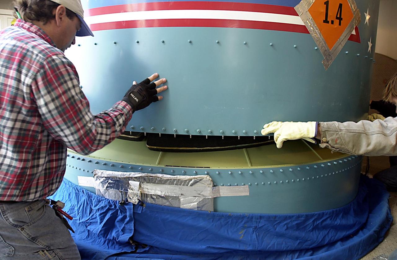
KENNEDY SPACE CENTER, FLA. - Workers on the launch tower on NASA's Space Launch Complex 2 (SLC-2), Vandenberg Air Force Base, Calif., help guide the interstage of the Delta II rocket into position for mating with the first stage. The rocket will carry the ICESat and CHIPSat satellites into Earth orbits. ICESat is a 661-pound satellite known as Geoscience Laser Altimeter System (GLAS) that will revolutionize our understanding of ice and its role in global climate change and how we protect and understand our home planet. It will help scientists determine if the global sea level is rising or falling. It will look at the ice sheets that blanket the Earth's poles to see if they are growing or shrinking. It will assist in developing an understanding of how changes in the Earth's atmosphere and climate effect polar ice masses and global sea level. CHIPSat, a suitcase-size 131-pound satellite, will provide invaluable information into the origin, physical processes and properties of the hot gas contained in the interstellar medium. This can provide important clues about the formation and evolution of galaxies since the interstellar medium literally contains the seeds of future stars. The Delta II launch is scheduled for Jan. 11 between 4:45 p.m. - 5:30 p.m. PST.
KENNEDY SPACE CENTER, FLA. - Workers on the launch tower on NASA's Space Launch Complex 2 (SLC-2), Vandenberg Air Force Base, Calif., help guide the interstage of the Delta II rocket into position for mating with the first stage. The rocket will carry the ICESat and CHIPSat satellites into Earth orbits. ICESat is a 661-pound satellite known as Geoscience Laser Altimeter System (GLAS) that will revolutionize our understanding of ice and its role in global climate change and how we protect and understand our home planet. It will help scientists determine if the global sea level is rising or falling. It will look at the ice sheets that blanket the Earth's poles to see if they are growing or shrinking. It will assist in developing an understanding of how changes in the Earth's atmosphere and climate effect polar ice masses and global sea level. CHIPSat, a suitcase-size 131-pound satellite, will provide invaluable information into the origin, physical processes and properties of the hot gas contained in the interstellar medium. This can provide important clues about the formation and evolution of galaxies since the interstellar medium literally contains the seeds of future stars. The Delta II launch is scheduled for Jan. 11 between 4:45 p.m. - 5:30 p.m. PST.
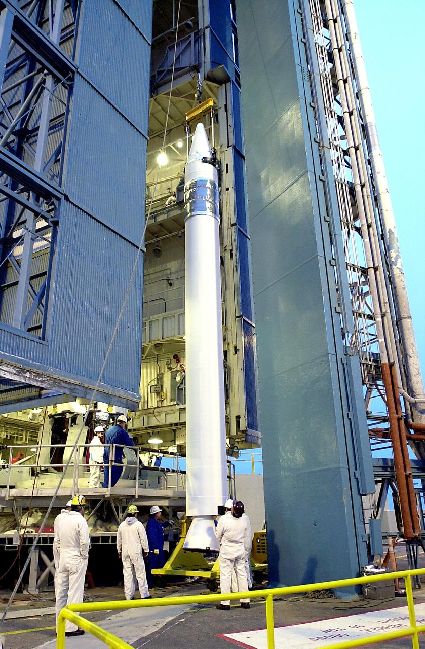
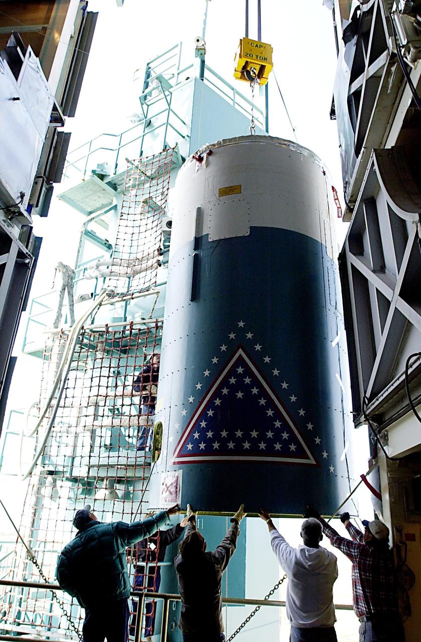
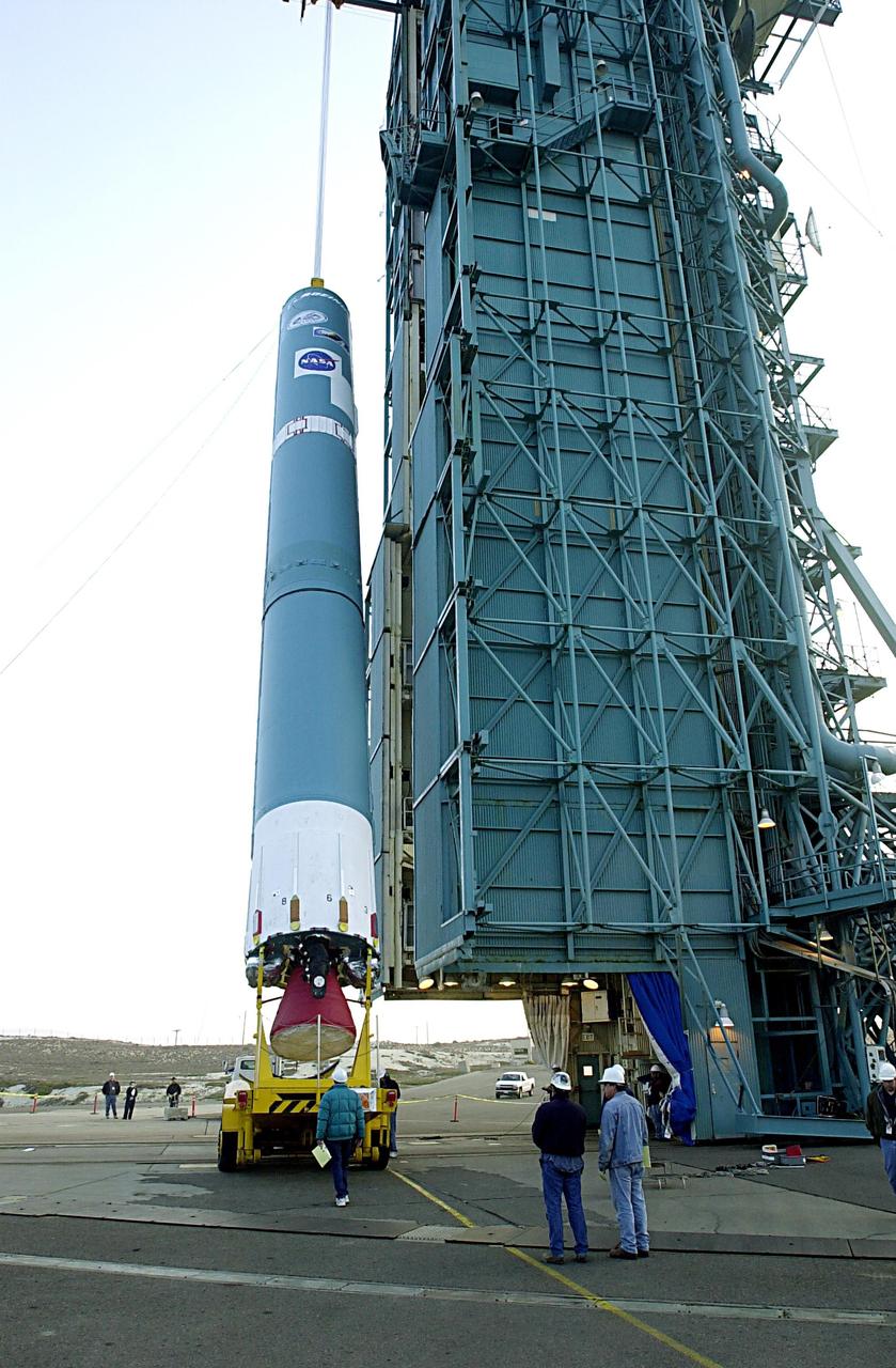
KENNEDY SPACE CENTER, FLA. - On the launch tower on NASA's Space Launch Complex 2 (SLC-2), Vandenberg Air Force Base, Calif., a solid rocket booster is lifted into an upright position as preparations continue to mate it to a Delta II rocket. The rocket will carry the ICESat and CHIPSat satellites into Earth orbits. ICESat is a 661-pound satellite known as Geoscience Laser Altimeter System (GLAS) that will revolutionize our understanding of ice and its role in global climate change and how we protect and understand our home planet. It will help scientists determine if the global sea level is rising or falling. It will look at the ice sheets that blanket the Earth's poles to see if they are growing or shrinking. It will assist in developing an understanding of how changes in the Earth's atmosphere and climate effect polar ice masses and global sea level. CHIPSat, a suitcase-size 131-pound satellite, will provide invaluable information into the origin, physical processes and properties of the hot gas contained in the interstellar medium. This can provide important clues about the formation and evolution of galaxies since the interstellar medium literally contains the seeds of future stars. The Delta II launch is scheduled for Jan. 11 between 4:45 p.m. - 5:30 p.m. PST.
KENNEDY SPACE CENTER, FLA. - The first stage of the Delta II rocket is raised to a vertical position at NASA's Space Launch Complex 2 (SLC-2) at Vandenberg Air Force Base, Calif. The rocket will carry the ICESat and CHIPSat satellites into Earth orbits. ICESat is a 661-pound satellite known as Geoscience Laser Altimeter System (GLAS) that will revolutionize our understanding of ice and its role in global climate change and how we protect and understand our home planet. It will help scientists determine if the global sea level is rising or falling. It will look at the ice sheets that blanket the Earth's poles to see if they are growing or shrinking. It will assist in developing an understanding of how changes in the Earth's atmosphere and climate effect polar ice masses and global sea level. CHIPSat, a suitcase-size 131-pound satellite, will provide invaluable information into the origin, physical processes and properties of the hot gas contained in the interstellar medium. This can provide important clues about the formation and evolution of galaxies since the interstellar medium literally contains the seeds of future stars. The Delta II launch is scheduled for Jan. 11 between 4:45 p.m. - 5:30 p.m. PST.

KENNEDY SPACE CENTER, FLA. - The first stage of the Delta II rocket is in the process of being raised to a vertical position on NASA's Space Launch Complex 2 (SLC-2) at Vandenberg Air Force Base, Calif. The rocket will carry the ICESat and CHIPSat satellites into Earth orbits. ICESat is a 661-pound satellite known as Geoscience Laser Altimeter System (GLAS) that will revolutionize our understanding of ice and its role in global climate change and how we protect and understand our home planet. It will help scientists determine if the global sea level is rising or falling. It will look at the ice sheets that blanket the Earth's poles to see if they are growing or shrinking. It will assist in developing an understanding of how changes in the Earth's atmosphere and climate effect polar ice masses and global sea level. CHIPSat, a suitcase-size 131-pound satellite, will provide invaluable information into the origin, physical processes and properties of the hot gas contained in the interstellar medium. This can provide important clues about the formation and evolution of galaxies since the interstellar medium literally contains the seeds of future stars. The Delta II launch is scheduled for Jan. 11 between 4:45 p.m. - 5:30 p.m. PST.
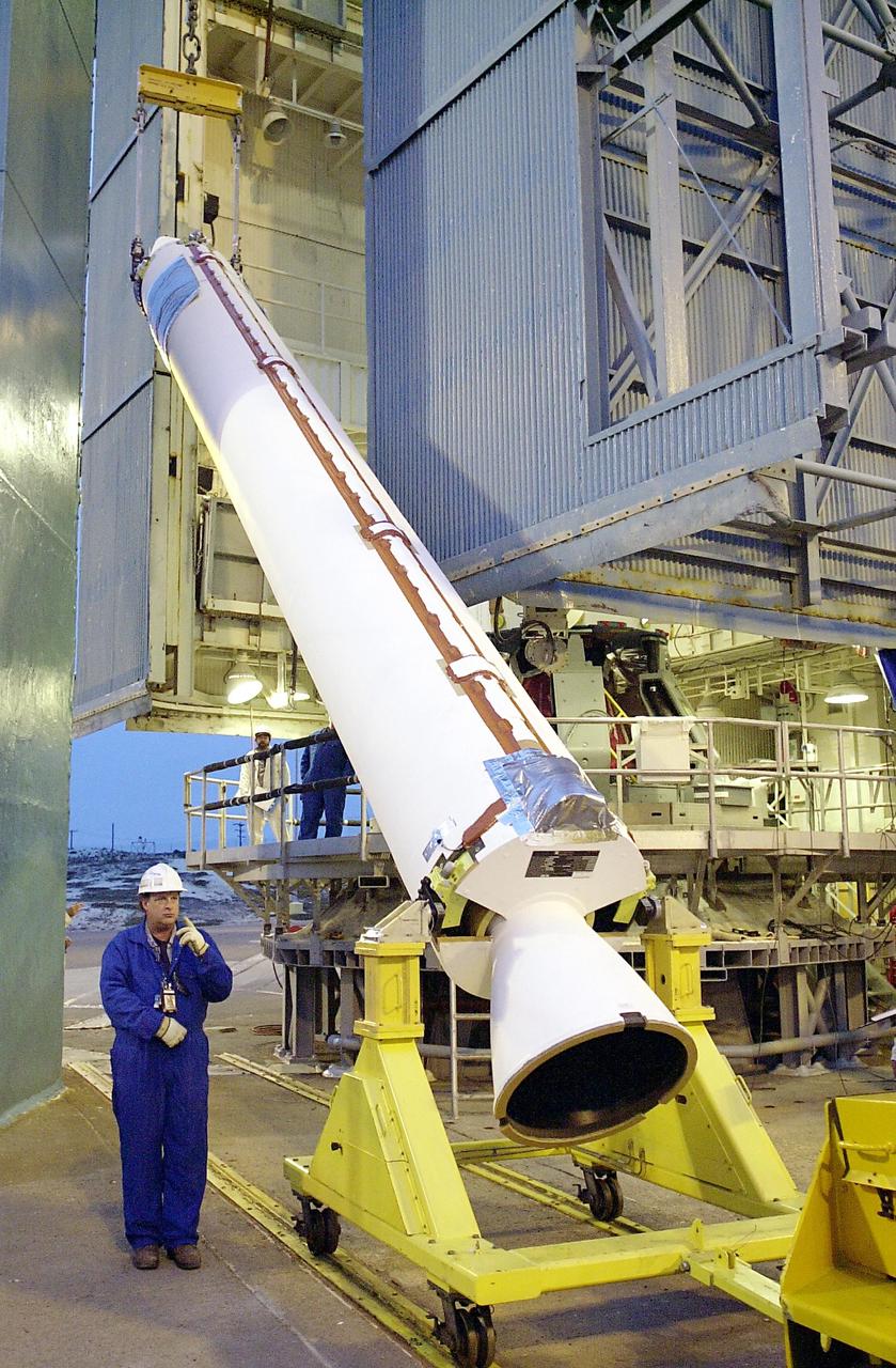
KENNEDY SPACE CENTER, FLA. - On the launch tower on NASA's Space Launch Complex 2 (SLC-2), Vandenberg Air Force Base, Calif., a solid rocket booster is lifted into an upright position for mating to a Delta II rocket. The rocket will carry the ICESat and CHIPSat satellites into Earth orbits. ICESat is a 661-pound satellite known as Geoscience Laser Altimeter System (GLAS) that will revolutionize our understanding of ice and its role in global climate change and how we protect and understand our home planet. It will help scientists determine if the global sea level is rising or falling. It will look at the ice sheets that blanket the Earth's poles to see if they are growing or shrinking. It will assist in developing an understanding of how changes in the Earth's atmosphere and climate effect polar ice masses and global sea level. CHIPSat, a suitcase-size 131-pound satellite, will provide invaluable information into the origin, physical processes and properties of the hot gas contained in the interstellar medium. This can provide important clues about the formation and evolution of galaxies since the interstellar medium literally contains the seeds of future stars. The Delta II launch is scheduled for Jan. 11 between 4:45 p.m. - 5:30 p.m. PST.
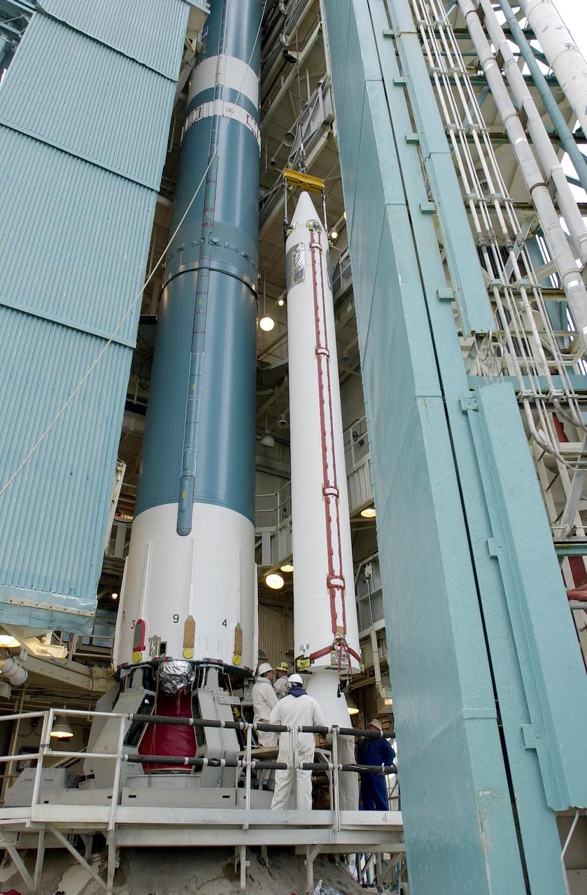
KENNEDY SPACE CENTER, FLA. - On the launch tower on NASA's Space Launch Complex 2 (SLC-2), Vandenberg Air Force Base, Calif., a solid rocket booster is lifted into an upright position beside the Delta II rocket to which it will be attached. The rocket will carry the ICESat and CHIPSat satellites into Earth orbits. ICESat is a 661-pound satellite known as Geoscience Laser Altimeter System (GLAS) that will revolutionize our understanding of ice and its role in global climate change and how we protect and understand our home planet. It will help scientists determine if the global sea level is rising or falling. It will look at the ice sheets that blanket the Earth's poles to see if they are growing or shrinking. It will assist in developing an understanding of how changes in the Earth's atmosphere and climate effect polar ice masses and global sea level. CHIPSat, a suitcase-size 131-pound satellite, will provide invaluable information into the origin, physical processes and properties of the hot gas contained in the interstellar medium. This can provide important clues about the formation and evolution of galaxies since the interstellar medium literally contains the seeds of future stars. The Delta II launch is scheduled for Jan. 11 between 4:45 p.m. - 5:30 p.m. PST.
The Perseus proof-of-concept vehicle flies over Rogers Dry Lake at the Dryden Flight Research Center, Edwards, California, to test basic design concepts for the remotely-piloted, high-altitude vehicle.
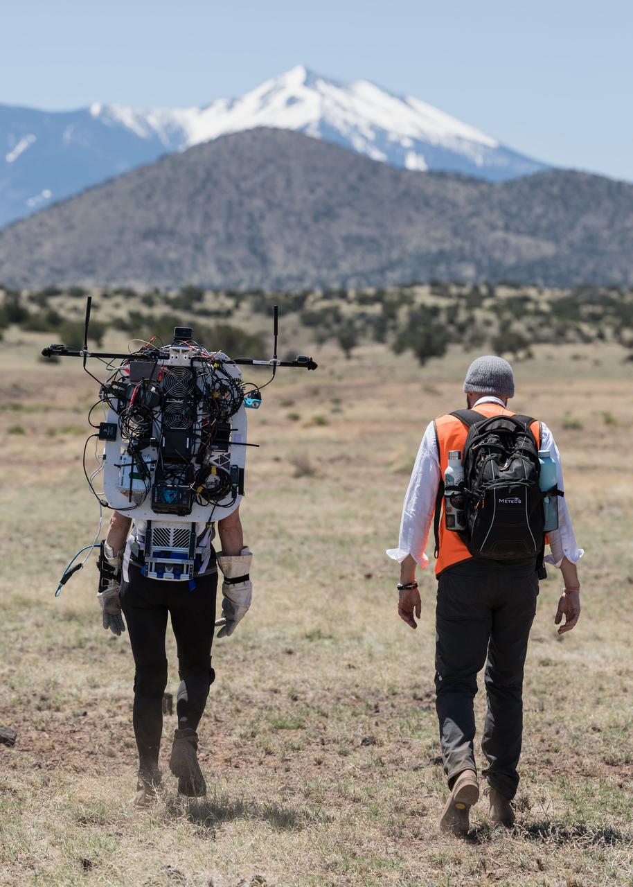
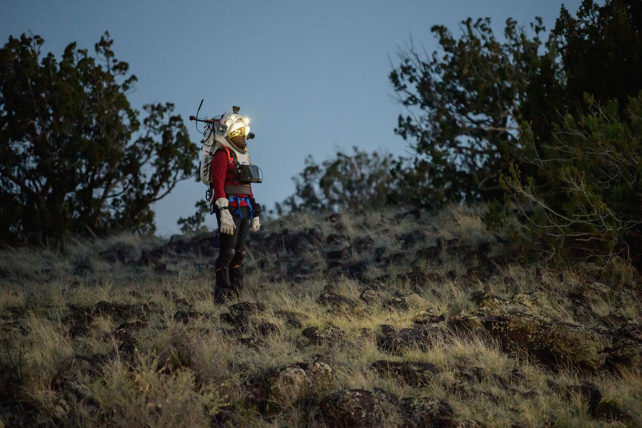
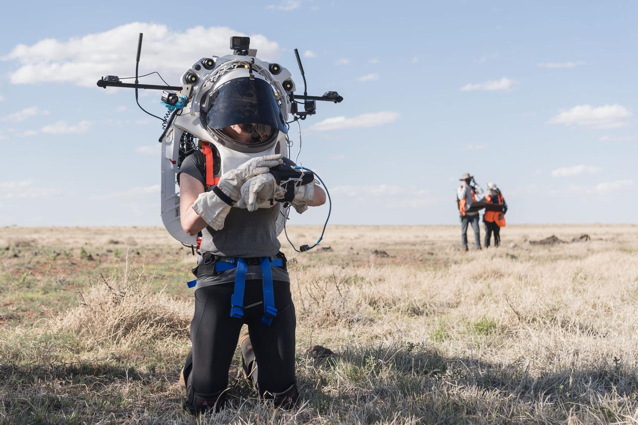
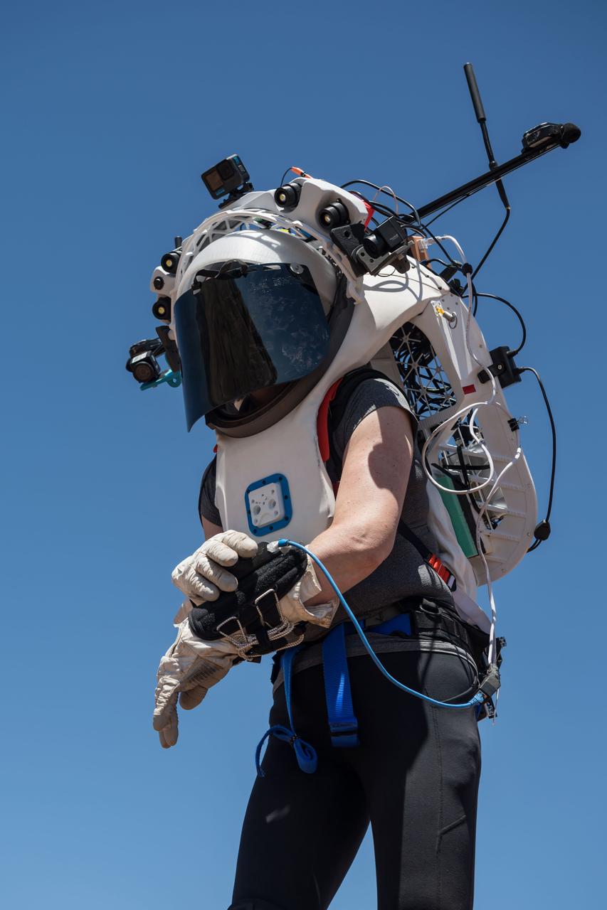
NASA astronaut Kate Rubins walks through the lunar-like landscape wearing the Joint AR (Joint Augmented Reality Visual Informatics System) display during an advanced technology run in the San Francisco Volcanic Field in Northern Arizona on May 19, 2024. The suit display features include navigation, photo capture, graphical format of consumables, procedure viewing, mission control updates, and other augmented reality cues and graphics. The team successfully tested navigation displays using data from four different data streams: GPS (Global Positioning System)/IMU (Inertial Measurement Unit), camera/IMU, LiDAR (Light Detection and Ranging), and static maps. Technology like this may be used for future Artemis missions to augment mission control communication and help guide crew back to the lunar lander. Credit: NASA/Josh Valcarcel
KENNEDY SPACE CENTER, FLA. -- Inside the Operations and Checkout Bldg. (O&C), an overhead crane removes the cover from the S0 truss segment beneath it. The S0 truss will undergo processing in the O&C during which the Canadian Mobile Transporter, power distribution system modules, a heat pipe radiator for cooling, computers, and a pair of rate gyroscopes will be installed. Four Global Positioning System antennas are already installed. A 44by 15-foot structure weighing 30,800 pounds when fully outfitted and ready for launch, the truss will be at the center of the ISS 10-truss, girderlike structure that will ultimately extend the length of a football field. Eventually the S0 truss will be attached to the U.S. Lab, "Destiny," which is scheduled to be added to the ISS in April 2000. Later, other trusses will be attached to the S0 on-orbit. The S0 truss is scheduled to be launched in the first quarter of 2001 on mission STS-108
KENNEDY SPACE CENTER, FLA. -- The S0 truss nears its resting place in the workstand in the O&C Bldg. (O&C). The S0 truss will undergo processing in the O&C during which the Canadian Mobile Transporter, power distribution system modules, a heat pipe radiator for cooling, computers, and a pair of rate gyroscopes will be installed. Four Global Positioning System antennas are already installed. A 44by 15-foot structure weighing 30,800 pounds when fully outfitted and ready for launch, the truss will be at the center of the ISS 10-truss, girderlike structure that will ultimately extend the length of a football field. Eventually the S0 truss will be attached to the U.S. Lab, "Destiny," which is scheduled to be added to the ISS in April 2000. Later, other trusses will be attached to the S0 on-orbit. The S0 truss is scheduled to be launched in the first quarter of 2001 on mission STS-108
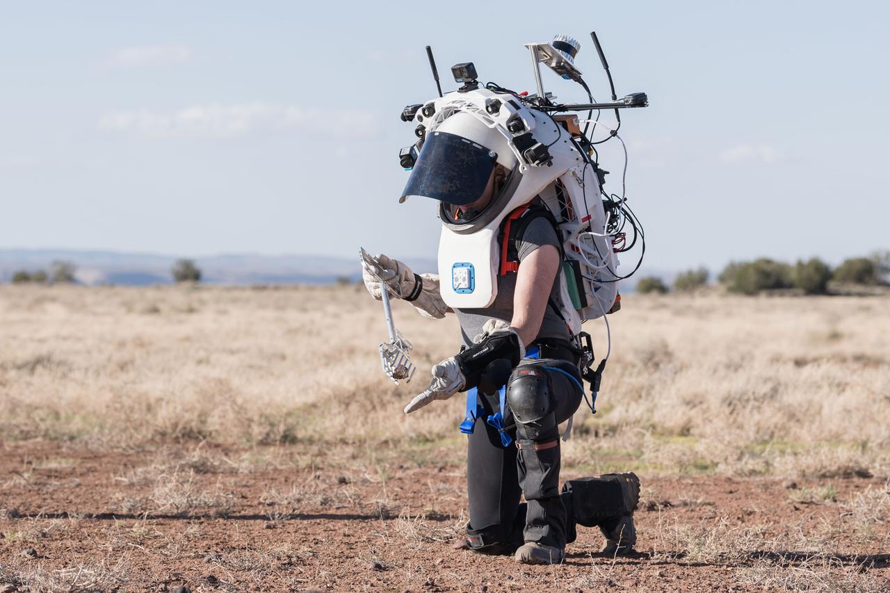
NASA astronaut Kate Rubins uses tongs to pick up a geologic sample while wearing the Joint AR (Joint Augmented Reality Visual Informatics System) display during an advanced technology run in the San Francisco Volcanic Field in Northern Arizona on May 21, 2024. The suit display features include navigation, photo capture, graphical format of consumables, procedure viewing, mission control updates, and other augmented reality cues and graphics. The team successfully tested navigation displays using data from four different data streams: GPS (Global Positioning System)/IMU (Inertial Measurement Unit), camera/IMU, LiDAR (Light Detection and Ranging), and static maps. Technology like this may be used for future Artemis missions to augment mission control communication and help guide crew back to the lunar lander. Credit: NASA/Josh Valcarcel
NASA astronaut Andre Douglas views the lunar-like landscape at dusk while wearing the Joint AR (Joint Augmented Reality Visual Informatics System) display during an advanced technology run in the San Francisco Volcanic Field in Northern Arizona on May 21, 2024. The suit display features include navigation, photo capture, graphical format of consumables, procedure viewing, mission control updates, and other augmented reality cues and graphics. The team successfully tested navigation displays using data from four different data streams: GPS (Global Positioning System)/IMU (Inertial Measurement Unit), camera/IMU, LiDAR (Light Detection and Ranging), and static maps. Technology like this may be used for future Artemis missions to augment mission control communication and help guide crew back to the lunar lander. Credit: NASA/Josh Valcarcel
KENNEDY SPACE CENTER, FLA. -- Workers in the O&C Bldg. watch as the S0 truss is lowered onto a workstand. The S0 truss will undergo processing in the O&C during which the Canadian Mobile Transporter, power distribution system modules, a heat pipe radiator for cooling, computers, and a pair of rate gyroscopes will be installed. Four Global Positioning System antennas are already installed. A 44by 15-foot structure weighing 30,800 pounds when fully outfitted and ready for launch, the truss will be at the center of the ISS 10-truss, girderlike structure that will ultimately extend the length of a football field. Eventually the S0 truss will be attached to the U.S. Lab, "Destiny," which is scheduled to be added to the ISS in April 2000. Later, other trusses will be attached to the S0 on-orbit. The S0 truss is scheduled to be launched in the first quarter of 2001 on mission STS-108
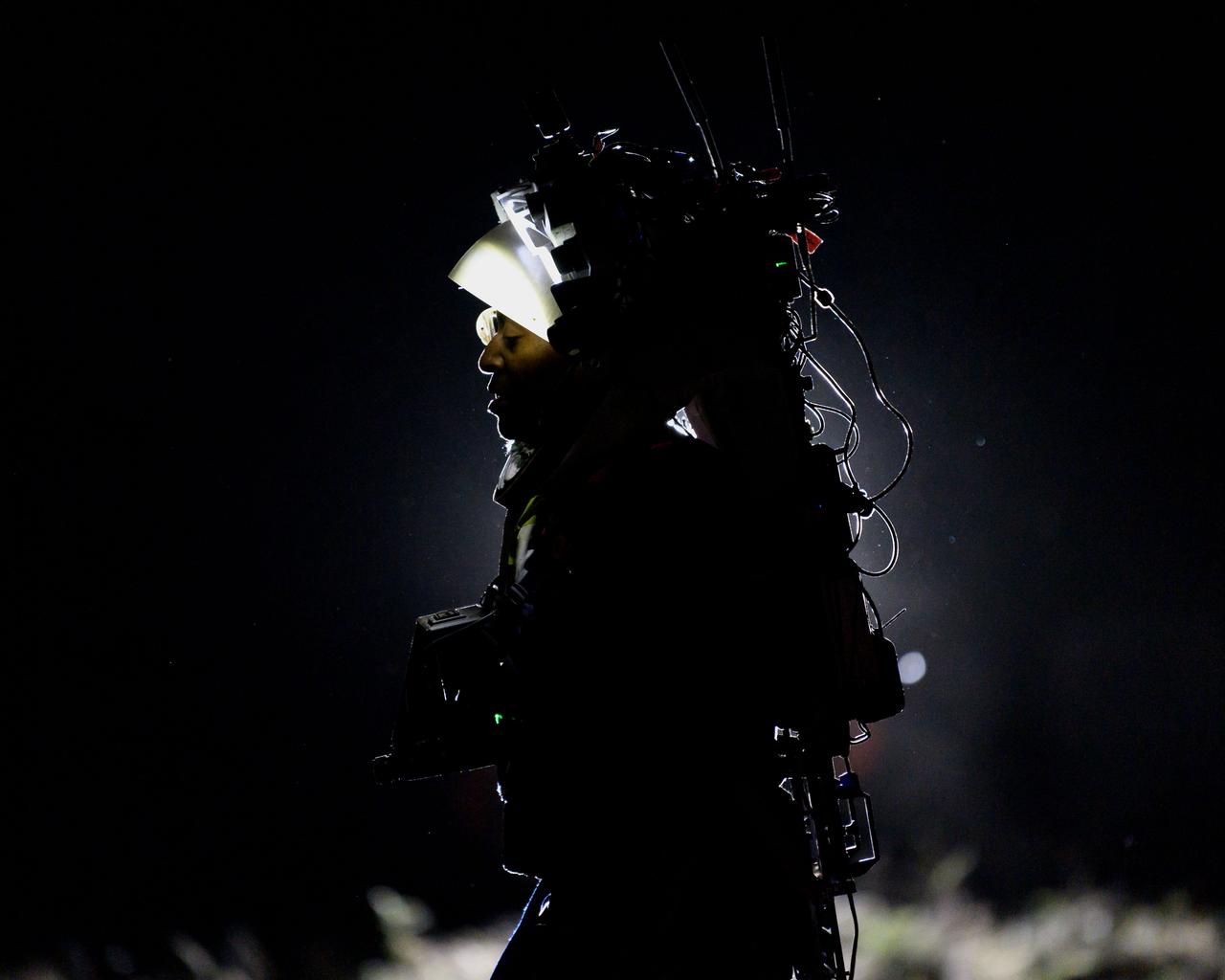
NASA astronaut Andre Douglas wears the Joint AR (Joint Augmented Reality Visual Informatics System) display during a nighttime advanced technology run in the San Francisco Volcanic Field in Northern Arizona on May 21, 2024. The suit display features include navigation, photo capture, graphical format of consumables, procedure viewing, mission control updates, and other augmented reality cues and graphics. The team successfully tested navigation displays using data from four different data streams: GPS (Global Positioning System)/IMU (Inertial Measurement Unit), camera/IMU, LiDAR (Light Detection and Ranging), and static maps. Technology like this may be used for future Artemis missions to augment mission control communication and help guide crew back to the lunar lander. Credit: NASA/Josh Valcarcel
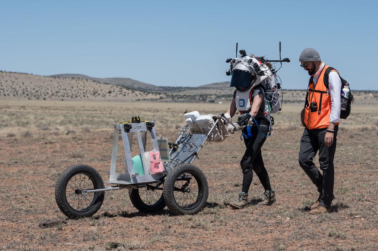
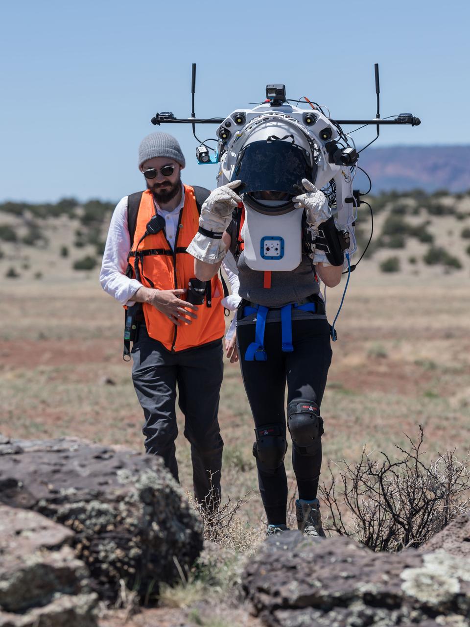
NASA astronaut Kate Rubins pushes a cart through the lunar-like landscape while wearing the Joint AR (Joint Augmented Reality Visual Informatics System) display during an advanced technology run in the San Francisco Volcanic Field in Northern Arizona on May 19, 2024. The suit display features include navigation, photo capture, graphical format of consumables, procedure viewing, mission control updates, and other augmented reality cues and graphics. The team successfully tested navigation displays using data from four different data streams: GPS (Global Positioning System)/IMU (Inertial Measurement Unit), camera/IMU, LiDAR (Light Detection and Ranging), and static maps. Technology like this may be used for future Artemis missions to augment mission control communication and help guide crew back to the lunar lander. Credit: NASA/Josh Valcarcel

KENNEDY SPACE CENTER, FLA. -- In the Operations and Checkout Bldg. (O&C), an overhead crane moves the S0 truss segment toward a workstand. The S0 truss will undergo processing in the O&C during which the Canadian Mobile Transporter, power distribution system modules, a heat pipe radiator for cooling, computers, and a pair of rate gyroscopes will be installed. Four Global Positioning System antennas are already installed. A 44by 15-foot structure weighing 30,800 pounds when fully outfitted and ready for launch, the truss will be at the center of the ISS 10-truss, girderlike structure that will ultimately extend the length of a football field. Eventually the S0 truss will be attached to the U.S. Lab, "Destiny," which is scheduled to be added to the ISS in April 2000. Later, other trusses will be attached to the S0 on-orbit. The S0 truss is scheduled to be launched in the first quarter of 2001 on mission STS-108
NASA astronaut Kate Rubins uses the hand controller on her wrist to display information while wearing the Joint AR (Joint Augmented Reality Visual Informatics System) display during an advanced technology run in the San Francisco Volcanic Field in Northern Arizona on May 21, 2024. The suit display features include navigation, photo capture, graphical format of consumables, procedure viewing, mission control updates, and other augmented reality cues and graphics. The team successfully tested navigation displays using data from four different data streams: GPS (Global Positioning System)/IMU (Inertial Measurement Unit), camera/IMU, LiDAR (Light Detection and Ranging), and static maps. Technology like this may be used for future Artemis missions to augment mission control communication and help guide crew back to the lunar lander. Credit: NASA/Josh Valcarcel
KENNEDY SPACE CENTER, FLA. -- Inside the Operations and Checkout Bldg. (O&C), workers (at left) watch over the maneuvering of the overhead crane toward the S0 truss segment below it. The S0 truss will undergo processing in the O&C during which the Canadian Mobile Transporter, power distribution system modules, a heat pipe radiator for cooling, computers, and a pair of rate gyroscopes will be installed. Four Global Positioning System antennas are already installed. A 44by 15-foot structure weighing 30,800 pounds when fully outfitted and ready for launch, the truss will be at the center of the ISS 10-truss, girderlike structure that will ultimately extend the length of a football field. Eventually the S0 truss will be attached to the U.S. Lab, "Destiny," which is scheduled to be added to the ISS in April 2000. Later, other trusses will be attached to the S0 on-orbit. The S0 truss is scheduled to be launched in the first quarter of 2001 on mission STS-108
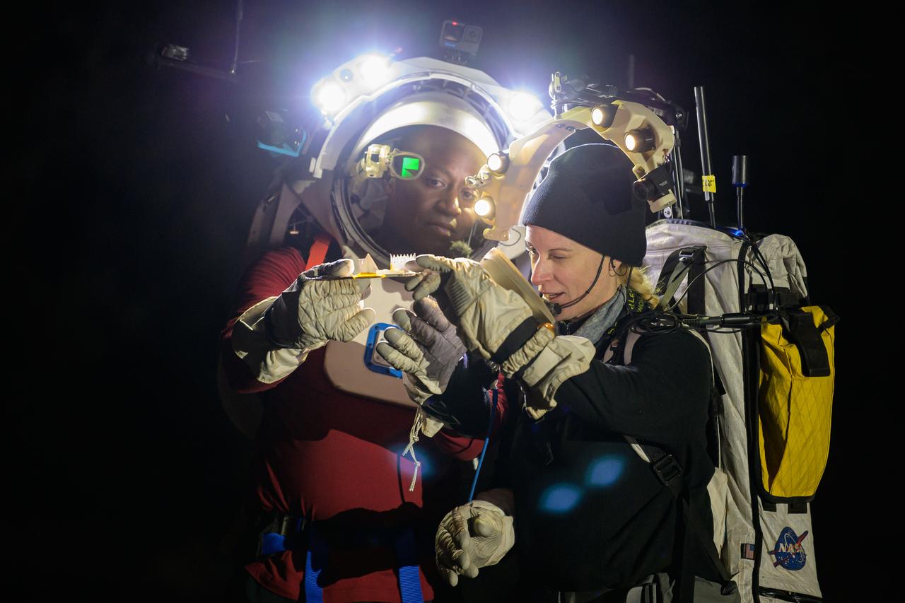
NASA astronauts Andre Douglas and Kate Rubins during a nighttime advanced technology run in the San Francisco Volcanic Field in Northern Arizona on May 21, 2024. Douglas is wearing the Joint AR (Joint Augmented Reality Visual Informatics System) display. The suit display features include navigation, photo capture, graphical format of consumables, procedure viewing, mission control updates, and other augmented reality cues and graphics. The team successfully tested navigation displays using data from four different data streams: GPS (Global Positioning System)/IMU (Inertial Measurement Unit), camera/IMU, LiDAR (Light Detection and Ranging), and static maps. Technology like this may be used for future Artemis missions to augment mission control communication and help guide crew back to the lunar lander. Credit: NASA/Josh Valcarcel
KENNEDY SPACE CENTER, FLA. -- Inside the Operations and Checkout Bldg. (O&C), an overhead crane is centered over the S0 truss segment before lowering. The crane will move it to a workstand in the O&C where it will undergo processing. In the foreground is the protective cover just removed. During the processing, the Canadian Mobile Transporter, power distribution system modules, a heat pipe radiator for cooling, computers, and a pair of rate gyroscopes will be installed. Four Global Positioning System antennas are already installed. A 44by 15-foot structure weighing 30,800 pounds when fully outfitted and ready for launch, the truss will be at the center of the ISS 10-truss, girderlike structure that will ultimately extend the length of a football field. Eventually the S0 truss will be attached to the U.S. Lab, "Destiny," which is scheduled to be added to the ISS in April 2000. Later, other trusses will be attached to the S0 on-orbit. The S0 truss is scheduled to be launched in the first quarter of 2001 on mission STS-108
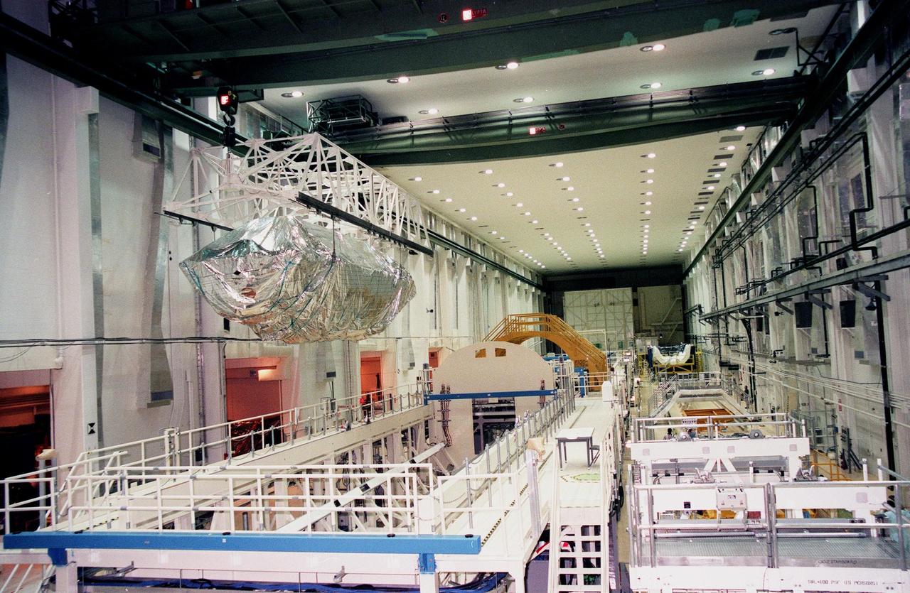
KENNEDY SPACE CENTER, FLA. -- In the Operations and Checkout Bldg. (O&C), an overhead crane moves the S0 truss segment toward a workstand. The S0 truss will undergo processing in the O&C during which the Canadian Mobile Transporter, power distribution system modules, a heat pipe radiator for cooling, computers and a pair of rate gyroscopes will be installed. Four Global Positioning System antennas are already installed. A 44- by 15-foot structure weighing 30,800 pounds when fully outfitted and ready for launch, the truss will be at the center of the ISS 10-truss, girderlike structure that will ultimately extend the length of a football field. Eventually the S0 truss will be attached to the U.S. Lab, "Destiny," which is scheduled to be added to the ISS in April 2000. Later, other trusses will be attached to the S0 on orbit. The S0 truss is scheduled to be launched in the first quarter of 2001 on mission STS-108
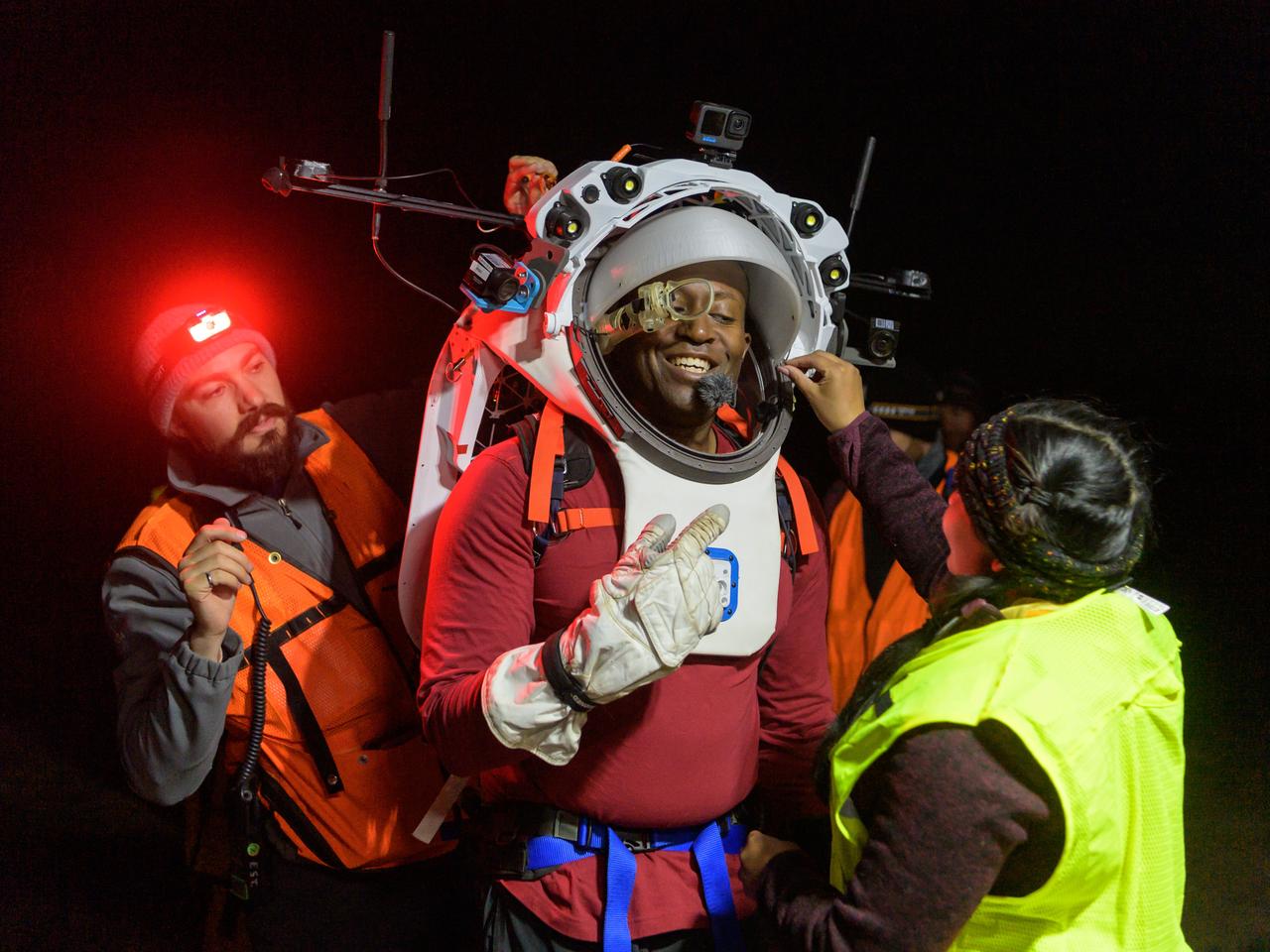
Engineers help NASA astronaut Andre Douglas adjust the Joint AR (Joint Augmented Reality Visual Informatics System) display he’s wearing during a nighttime advanced technology run in the San Francisco Volcanic Field in Northern Arizona on May 21, 2024. The suit display features include navigation, photo capture, graphical format of consumables, procedure viewing, mission control updates, and other augmented reality cues and graphics. The team successfully tested navigation displays using data from four different data streams: GPS (Global Positioning System)/IMU (Inertial Measurement Unit), camera/IMU, LiDAR (Light Detection and Ranging), and static maps. Technology like this may be used for future Artemis missions to augment mission control communication and help guide crew back to the lunar lander. Credit: NASA/Josh Valcarcel
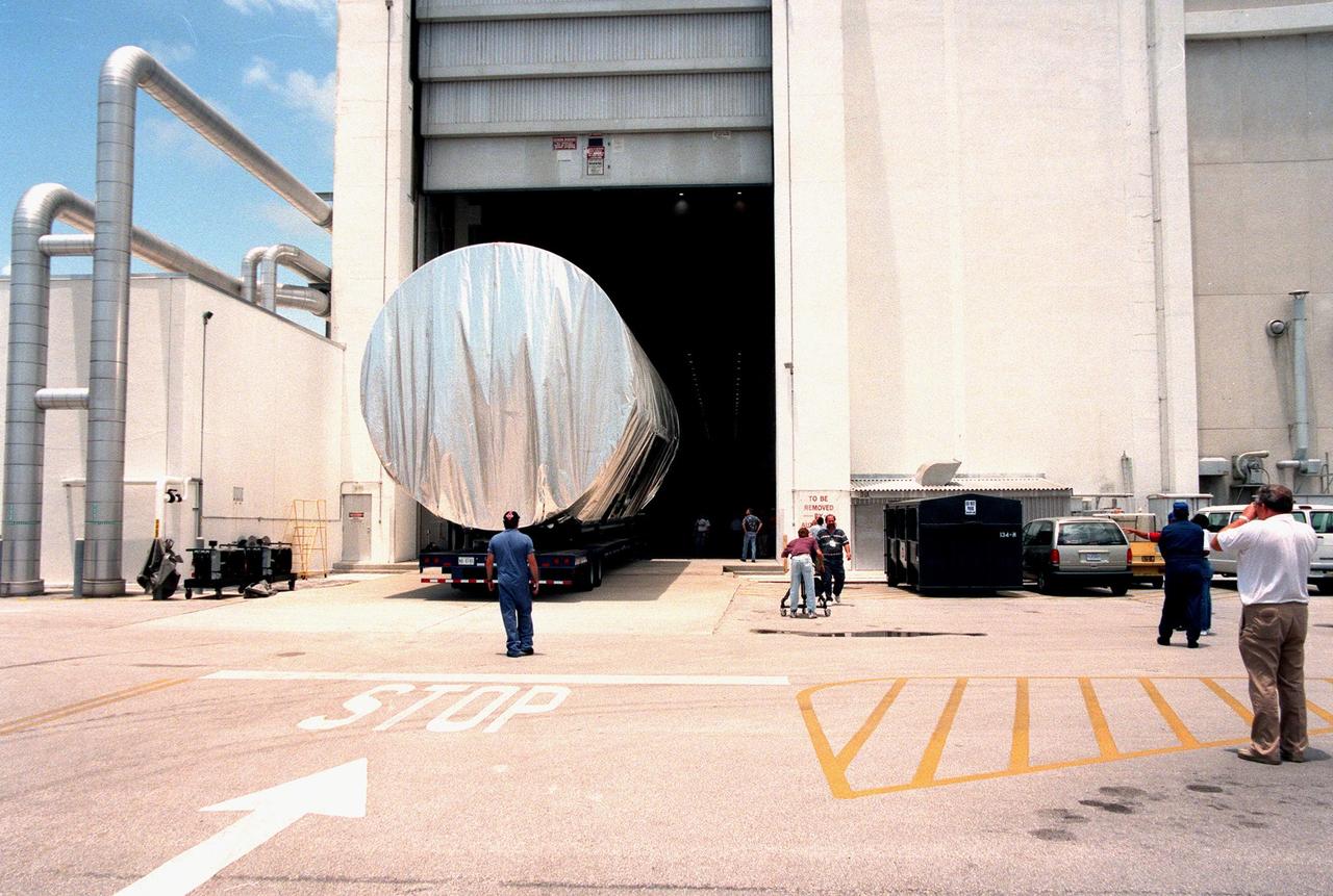
KENNEDY SPACE CENTER, FLA. -- The S0 truss segment is moved into the Operations and Checkout Bldg. (O&C) for processing. The truss arrived at the SLF aboard a "Super Guppy" aircraft from Boeing in Huntington, Calif. During processing in the O&C, the S0 truss will have installed the Canadian Mobile Transporter, power distribution system modules, a heat pipe radiator for cooling, computers, and a pair of rate gyroscopes. Four Global Positioning System antennas are already installed. A 44by 15-foot structure weighing 30,800 pounds when fully outfitted and ready for launch, the truss will be at the center of the ISS 10-truss, girderlike structure that will ultimately extend the length of a football field. Eventually the S0 truss will be attached to the U.S. Lab, "Destiny," which is scheduled to be added to the ISS in April 2000. Later, other trusses will be attached to the S0 on-orbit. The S0 truss is scheduled to be launched in the first quarter of 2001 on mission STS-108
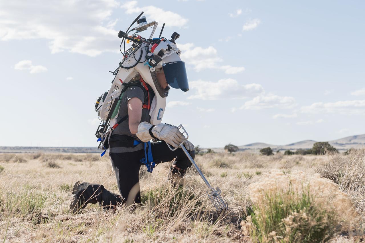
NASA astronaut Kate Rubins uses tongs to collect geologic samples while wearing the Joint AR (Joint Augmented Reality Visual Informatics System) display during an advanced technology run in the San Francisco Volcanic Field in Northern Arizona on May 21, 2024. The suit display features include navigation, photo capture, graphical format of consumables, procedure viewing, mission control updates, and other augmented reality cues and graphics. The team successfully tested navigation displays using data from four different data streams: GPS (Global Positioning System)/IMU (Inertial Measurement Unit), camera/IMU, LiDAR (Light Detection and Ranging), and static maps. Technology like this may be used for future Artemis missions to augment mission control communication and help guide crew back to the lunar lander. Credit: NASA/Josh Valcarcel
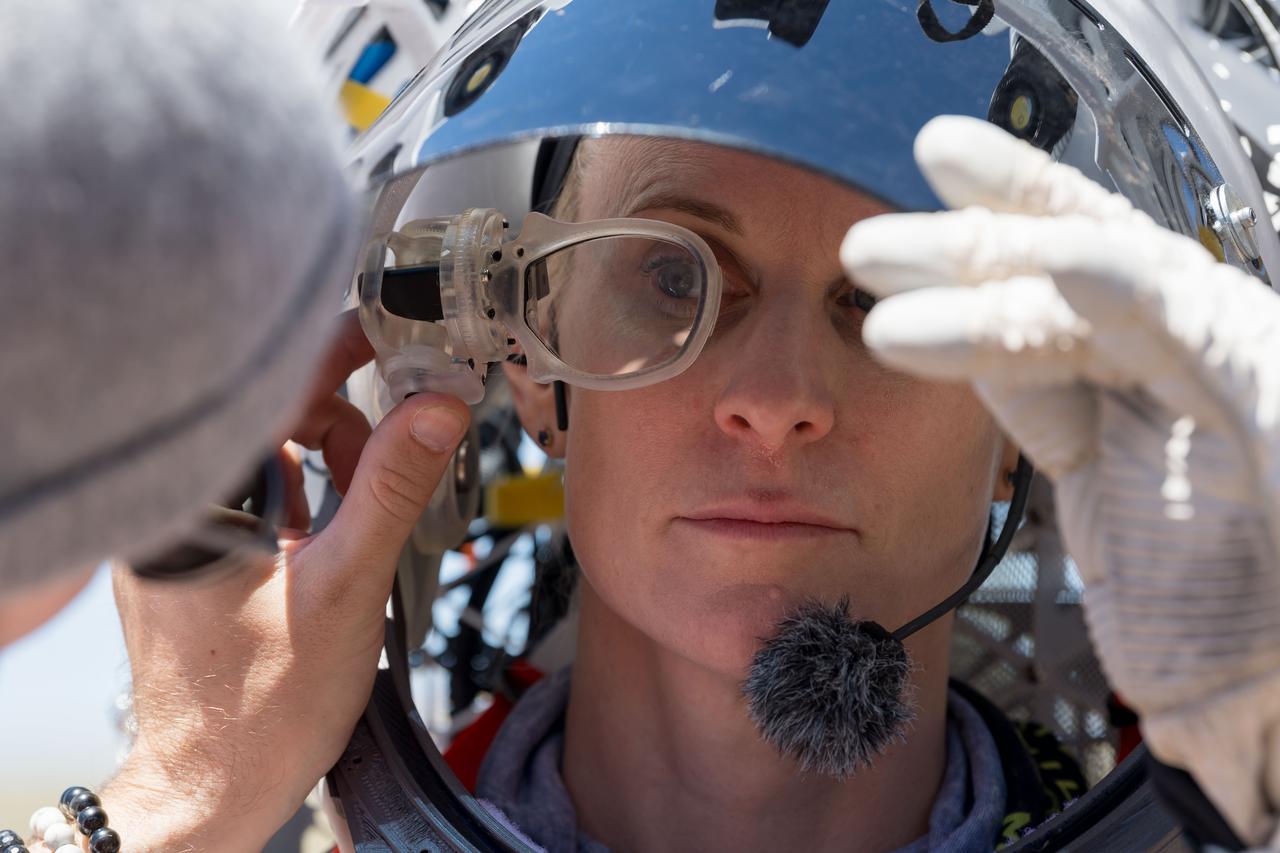
An engineer helps NASA astronaut Kate Rubins adjust the lens on the Joint AR (Joint Augmented Reality Visual Informatics System) display she’s wearing during an advanced technology run in the San Francisco Volcanic Field in Northern Arizona on May 19, 2024. The suit display features include navigation, photo capture, graphical format of consumables, procedure viewing, mission control updates, and other augmented reality cues and graphics. The team successfully tested navigation displays using data from four different data streams: GPS (Global Positioning System)/IMU (Inertial Measurement Unit), camera/IMU, LiDAR (Light Detection and Ranging), and static maps. Technology like this may be used for future Artemis missions to augment mission control communication and help guide crew back to the lunar lander. Credit: NASA/Josh Valcarcel
NASA astronaut Kate Rubins uses the hand controller on her wrist to display information while wearing the Joint AR (Joint Augmented Reality Visual Informatics System) display during an advanced technology run in the San Francisco Volcanic Field in Northern Arizona on May 19, 2024. The suit display features include navigation, photo capture, graphical format of consumables, procedure viewing, mission control updates, and other augmented reality cues and graphics. The team successfully tested navigation displays using data from four different data streams: GPS (Global Positioning System)/IMU (Inertial Measurement Unit), camera/IMU, LiDAR (Light Detection and Ranging), and static maps. Technology like this may be used for future Artemis missions to augment mission control communication and help guide crew back to the lunar lander. Credit: NASA/Josh Valcarcel
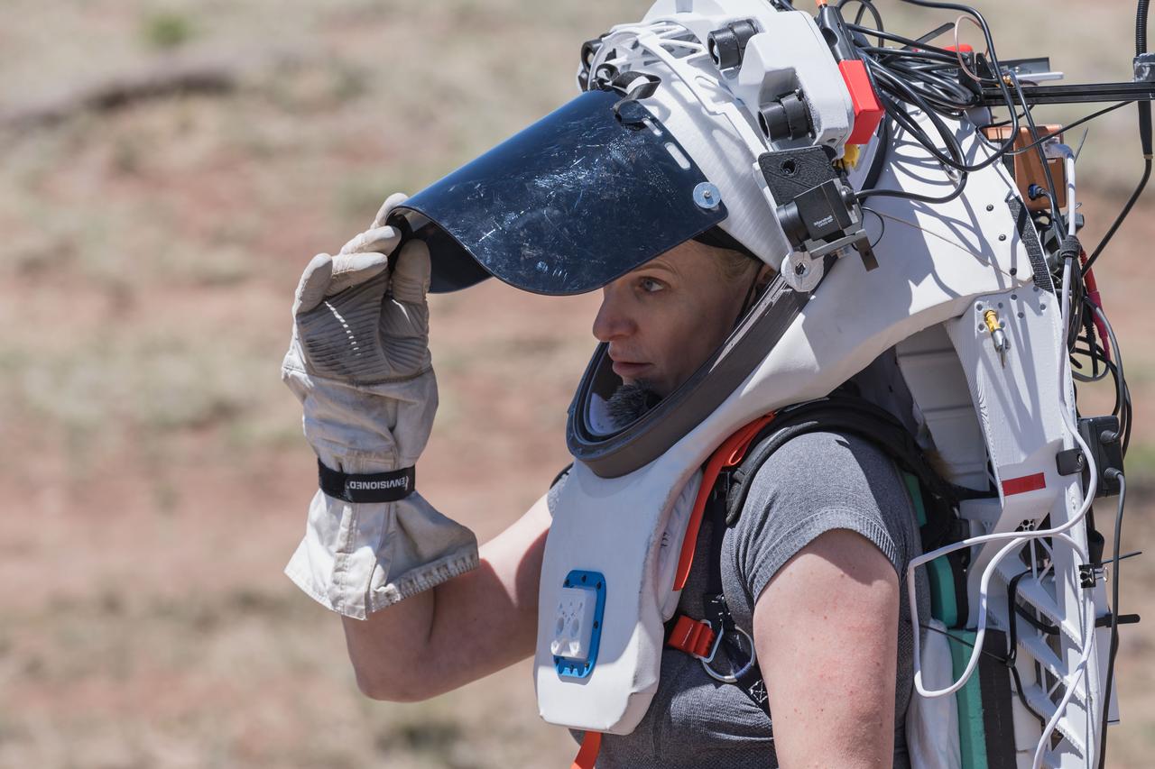
NASA astronaut Kate Rubins opens the sun visor on the Joint AR (Joint Augmented Reality Visual Informatics System) display she’s wearing during an advanced technology run in the San Francisco Volcanic Field in Northern Arizona on May 19, 2024. The suit display features include navigation, photo capture, graphical format of consumables, procedure viewing, mission control updates, and other augmented reality cues and graphics. The team successfully tested navigation displays using data from four different data streams: GPS (Global Positioning System)/IMU (Inertial Measurement Unit), camera/IMU, LiDAR (Light Detection and Ranging), and static maps. Technology like this may be used for future Artemis missions to augment mission control communication and help guide crew back to the lunar lander. Credit: NASA/Josh Valcarcel
NASA astronaut Kate Rubins walks through the lunar-like landscape wearing the Joint AR (Joint Augmented Reality Visual Informatics System) display during an advanced technology run in the San Francisco Volcanic Field in Northern Arizona on May 19, 2024. The suit display features include navigation, photo capture, graphical format of consumables, procedure viewing, mission control updates, and other augmented reality cues and graphics. The team successfully tested navigation displays using data from four different data streams: GPS (Global Positioning System)/IMU (Inertial Measurement Unit), camera/IMU, LiDAR (Light Detection and Ranging), and static maps. Technology like this may be used for future Artemis missions to augment mission control communication and help guide crew back to the lunar lander. Credit: NASA/Josh Valcarcel
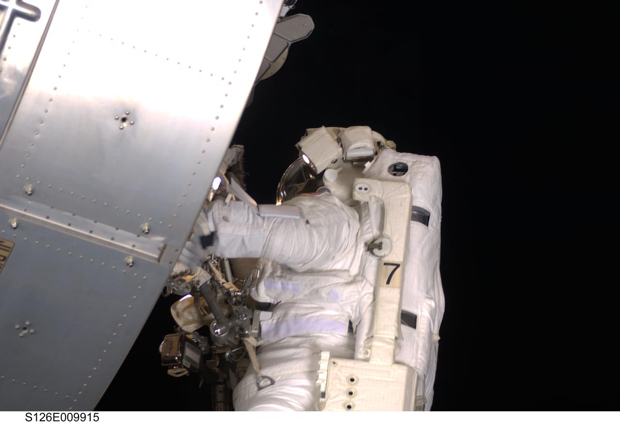
S126-E-009915 (24 Nov. 2008) --- Astronaut Steve Bowen, STS-126 mission specialist, participates in the mission's fourth and final scheduled session of extravehicular activity (EVA) as construction and maintenance continue on the International Space Station. During the six-hour, seven-minute spacewalk, Bowen and astronaut Shane Kimbrough (out of frame), mission specialist, completed the lubrication of the port Solar Alpha Rotary Joints (SARJ) as well as other station assembly tasks. Bowen returned to the starboard SARJ to install the final trundle bearing assembly, retracted a berthing mechanism latch on the Japanese Kibo Laboratory and reinstalled its thermal cover. Bowen also installed a video camera on the Port 1 truss and attached a Global Positioning System antenna on the Japanese Experiment Module Pressurized Section.
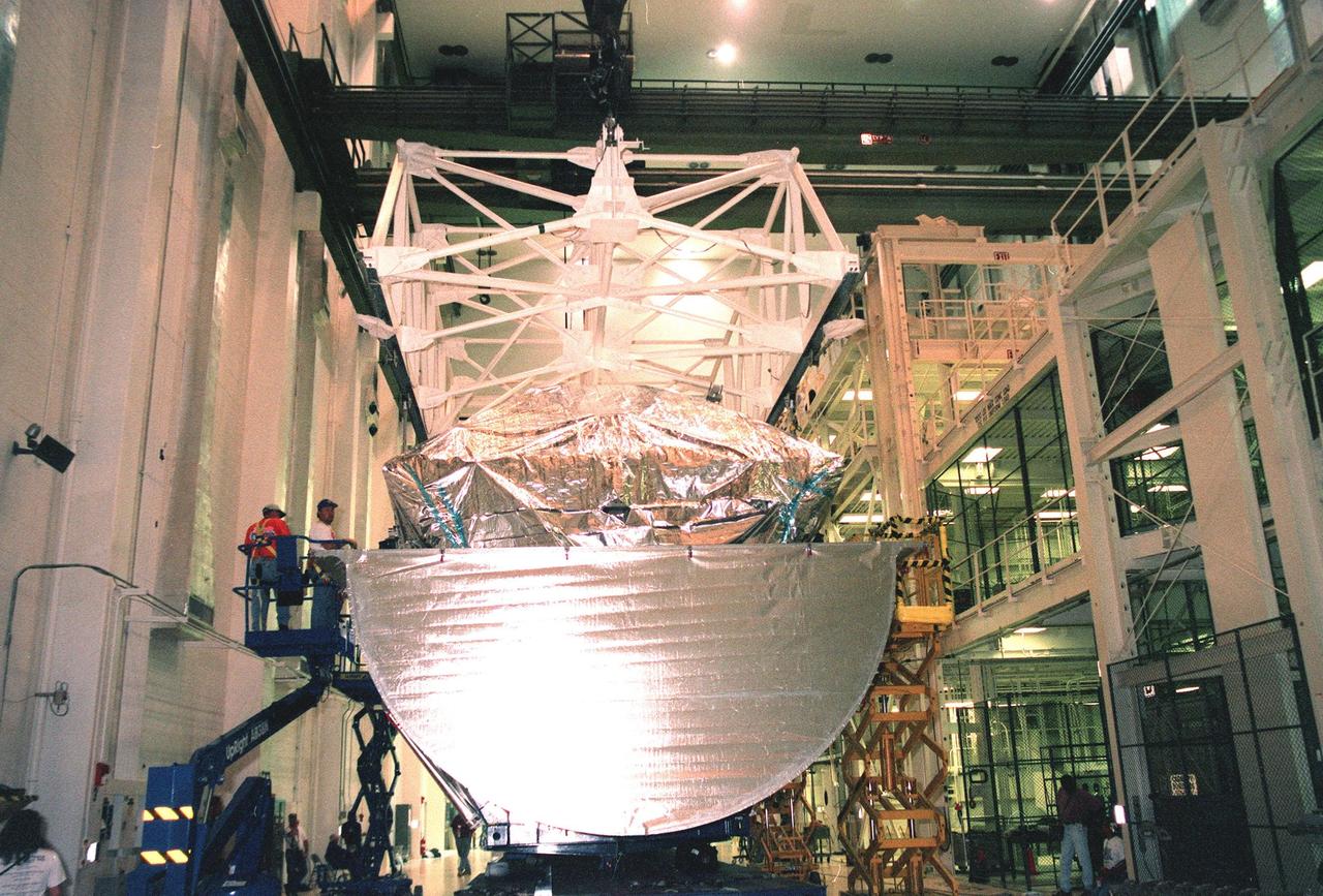
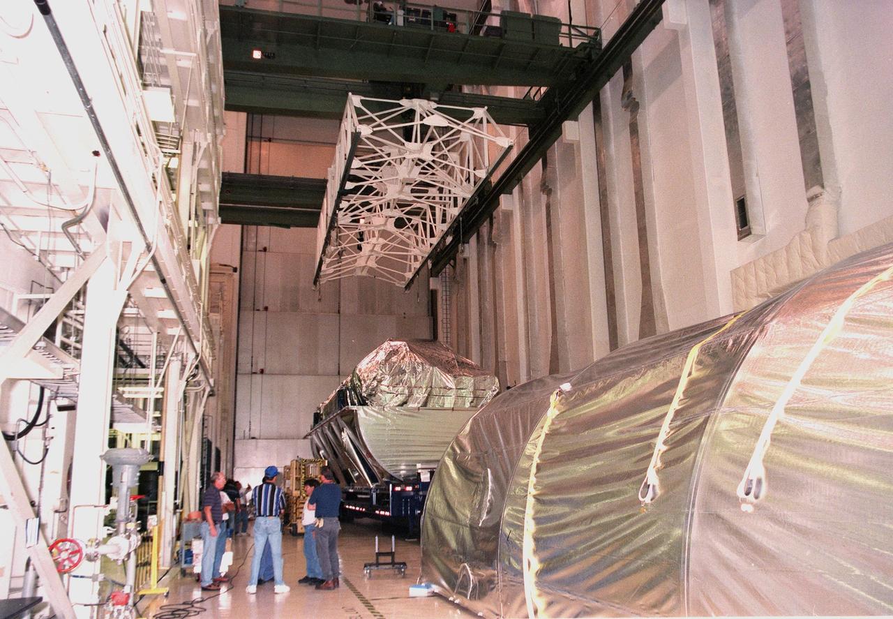
![The <a href=http://mars.jpl.nasa.gov/2001/>2001 Mars Odyssey Orbiter </a>comes to rest on a workstand in the Spacecraft Assembly & Encapsulation Facility -2. Workers check the spacecraft’s position. The Mars Odyssey Orbiter carries three science instruments: the Thermal Emission Imaging System (THEMIS), the Gamma Ray Spectrometer (GRS), and the Mars Radiation Environment Experiment (MARIE). THEMIS will map the mineralogy and morphology of the Martian surface using a high-resolution camera and a thermal infrared imaging spectrometer. The GRS will achieve global mapping of the elemental composition of the surface and determine the abundance of hydrogen in the shallow subsurface. [The GRS is a rebuild of the instrument lost with the Mars Observer mission.] The MARIE will characterize aspects of the near-space radiation environment as related to the radiation-related risk to human explorers. The Mars Odyssey Orbiter is scheduled for launch on April 7, 2001, aboard a Delta 7925 rocket from Launch Pad 17-A, Cape Canaveral Air Force Station](https://images-assets.nasa.gov/image/KSC01pp0102/KSC01pp0102~medium.jpg)
The <a href=http://mars.jpl.nasa.gov/2001/>2001 Mars Odyssey Orbiter </a>comes to rest on a workstand in the Spacecraft Assembly & Encapsulation Facility -2. Workers check the spacecraft’s position. The Mars Odyssey Orbiter carries three science instruments: the Thermal Emission Imaging System (THEMIS), the Gamma Ray Spectrometer (GRS), and the Mars Radiation Environment Experiment (MARIE). THEMIS will map the mineralogy and morphology of the Martian surface using a high-resolution camera and a thermal infrared imaging spectrometer. The GRS will achieve global mapping of the elemental composition of the surface and determine the abundance of hydrogen in the shallow subsurface. [The GRS is a rebuild of the instrument lost with the Mars Observer mission.] The MARIE will characterize aspects of the near-space radiation environment as related to the radiation-related risk to human explorers. The Mars Odyssey Orbiter is scheduled for launch on April 7, 2001, aboard a Delta 7925 rocket from Launch Pad 17-A, Cape Canaveral Air Force Station
![The <a href=http:__mars.jpl.nasa.gov_2001_>2001 Mars Odyssey Orbiter <_a>comes to rest on a workstand in the Spacecraft Assembly and Encapsulation Facility -2. Workers check the spacecraft’s position. The Mars Odyssey Orbiter carries three science instruments: the Thermal Emission Imaging System (THEMIS), the Gamma Ray Spectrometer (GRS), and the Mars Radiation Environment Experiment (MARIE). THEMIS will map the mineralogy and morphology of the Martian surface using a high-resolution camera and a thermal infrared imaging spectrometer. The GRS will achieve global mapping of the elemental composition of the surface and determine the abundance of hydrogen in the shallow subsurface. [The GRS is a rebuild of the instrument lost with the Mars Observer mission.] The MARIE will characterize aspects of the near-space radiation environment as related to the radiation-related risk to human explorers. The Mars Odyssey Orbiter is scheduled for launch on April 7, 2001, aboard a Delta 7925 rocket from Launch Pad 17-A, Cape Canaveral Air Force Station](https://images-assets.nasa.gov/image/01pp0102/01pp0102~medium.jpg)
The <a href=http:__mars.jpl.nasa.gov_2001_>2001 Mars Odyssey Orbiter <_a>comes to rest on a workstand in the Spacecraft Assembly and Encapsulation Facility -2. Workers check the spacecraft’s position. The Mars Odyssey Orbiter carries three science instruments: the Thermal Emission Imaging System (THEMIS), the Gamma Ray Spectrometer (GRS), and the Mars Radiation Environment Experiment (MARIE). THEMIS will map the mineralogy and morphology of the Martian surface using a high-resolution camera and a thermal infrared imaging spectrometer. The GRS will achieve global mapping of the elemental composition of the surface and determine the abundance of hydrogen in the shallow subsurface. [The GRS is a rebuild of the instrument lost with the Mars Observer mission.] The MARIE will characterize aspects of the near-space radiation environment as related to the radiation-related risk to human explorers. The Mars Odyssey Orbiter is scheduled for launch on April 7, 2001, aboard a Delta 7925 rocket from Launch Pad 17-A, Cape Canaveral Air Force Station
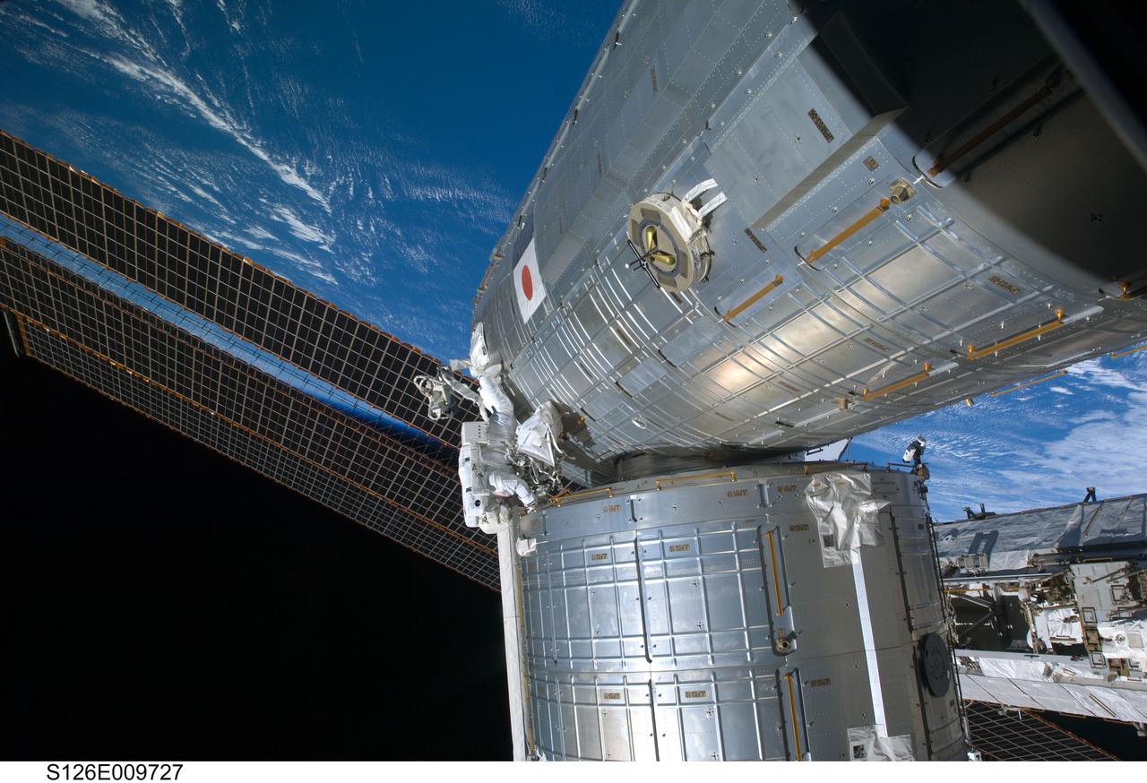
S126-E-009727 (24 Nov. 2008) --- Astronaut Steve Bowen, STS-126 mission specialist, participates in the mission's fourth and final scheduled session of extravehicular activity (EVA) as construction and maintenance continue on the International Space Station. During the six-hour, seven-minute spacewalk, Bowen and astronaut Shane Kimbrough (out of frame), mission specialist, completed the lubrication of the port Solar Alpha Rotary Joints (SARJ) as well as other station assembly tasks. Bowen returned to the starboard SARJ to install the final trundle bearing assembly, retracted a berthing mechanism latch on the Japanese Kibo Laboratory and reinstalled its thermal cover. Bowen also installed a video camera on the Port 1 truss and attached a Global Positioning System antenna on the Japanese Experiment Module Pressurized Section.
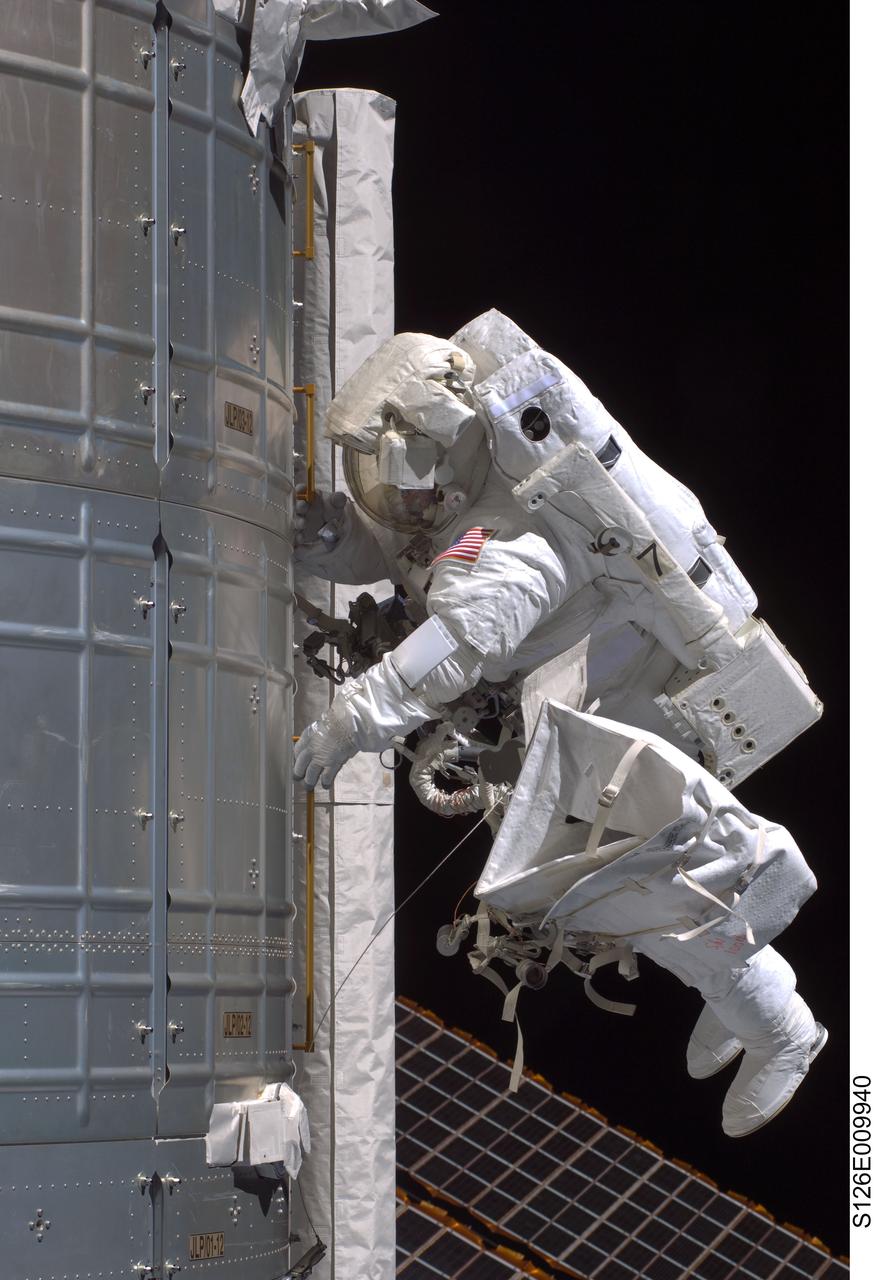
S126-E-009940 (24 Nov. 2008) --- Astronaut Steve Bowen, STS-126 mission specialist, participates in the mission's fourth and final scheduled session of extravehicular activity (EVA) as construction and maintenance continue on the International Space Station. During the six-hour, seven-minute spacewalk, Bowen and astronaut Shane Kimbrough (out of frame), mission specialist, completed the lubrication of the port Solar Alpha Rotary Joints (SARJ) as well as other station assembly tasks. Bowen returned to the starboard SARJ to install the final trundle bearing assembly, retracted a berthing mechanism latch on the Japanese Kibo Laboratory and reinstalled its thermal cover. Bowen also installed a video camera on the Port 1 truss and attached a Global Positioning System antenna on the Japanese Experiment Module Pressurized Section.
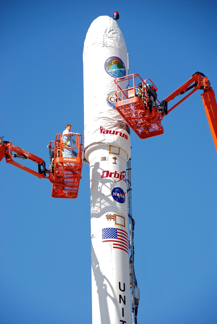
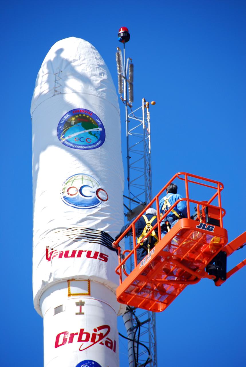
VANDENBERG AIR FORCE BASE, Calif. -- On Launch Complex 576-E at Vandenberg Air Force Base in California, Orbital Sciences Engineer Jose Castillo maneuvers the bucket truck at right into position over the fairing access door on NASA's Orbiting Carbon Observatory, or OCO. Glenn Weigle of Orbital Satellite Systems Group is on the bucket at left. Weigle is prepared to move in and inspect the GN2 instrument purge flow. OCO will collect precise global measurements of carbon dioxide (CO2) in the Earth's atmosphere. Scientists will analyze OCO data to improve our understanding of the natural processes and human activities that regulate the abundance and distribution of this important greenhouse gas. OCO is scheduled to launch Feb. 24 aboard an Orbital Sciences' Taurus XL rocket. Photo credit: NASA/Richard Nielsen, KSC
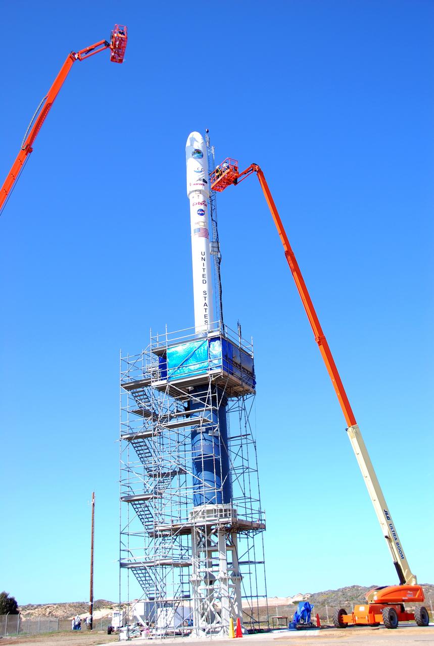
VANDENBERG AIR FORCE BASE, Calif. -- On Launch Complex 576-E at Vandenberg Air Force Base in California, Orbital Sciences Engineer Jose Castillo maneuvers the bucket truck into position over the fairing access door on NASA's Orbiting Carbon Observatory, or OCO. On the top of the OCO fairing is the shadow of Glenn Weigle of Orbital Satellite Systems Group, on the bucket at upper left, who is prepared to move in and inspect the GN2 instrument purge flow. OCO will collect precise global measurements of carbon dioxide (CO2) in the Earth's atmosphere. Scientists will analyze OCO data to improve our understanding of the natural processes and human activities that regulate the abundance and distribution of this important greenhouse gas. Photo credit: NASA/Richard Nielsen, KSC
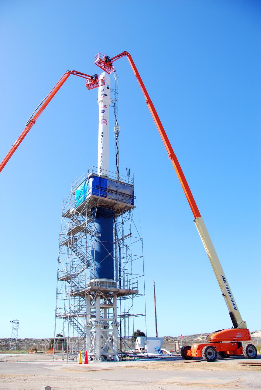
VANDENBERG AIR FORCE BASE, Calif. -- On Launch Complex 576-E at Vandenberg Air Force Base in California, Orbital Sciences Engineer Jose Castillo maneuvers the bucket truck at right into position over the fairing access door on NASA's Orbiting Carbon Observatory, or OCO. Glenn Weigle of Orbital Satellite Systems Group is on the bucket at left. Weigle is prepared to move in and inspect the GN2 instrument purge flow. OCO will collect precise global measurements of carbon dioxide (CO2) in the Earth's atmosphere. Scientists will analyze OCO data to improve our understanding of the natural processes and human activities that regulate the abundance and distribution of this important greenhouse gas. OCO is scheduled to launch Feb. 24 aboard an Orbital Sciences' Taurus XL rocket. Photo credit: NASA/Richard Nielsen, KSC
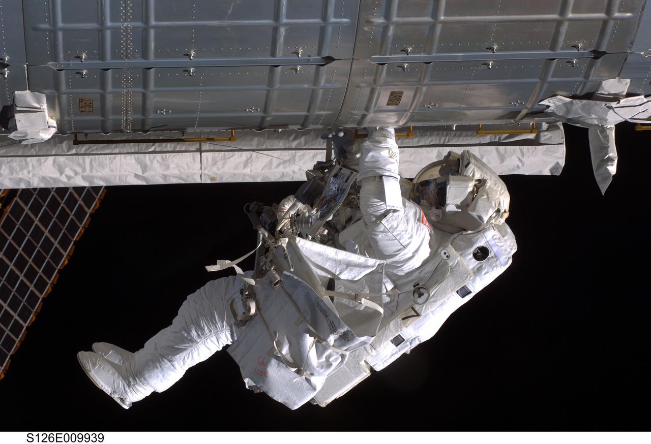
S126-E-009939 (24 Nov. 2008) --- Astronaut Steve Bowen, STS-126 mission specialist, participates in the mission's fourth and final scheduled session of extravehicular activity (EVA) as construction and maintenance continue on the International Space Station. During the six-hour, seven-minute spacewalk, Bowen and astronaut Shane Kimbrough (out of frame), mission specialist, completed the lubrication of the port Solar Alpha Rotary Joints (SARJ) as well as other station assembly tasks. Bowen returned to the starboard SARJ to install the final trundle bearing assembly, retracted a berthing mechanism latch on the Japanese Kibo Laboratory and reinstalled its thermal cover. Bowen also installed a video camera on the Port 1 truss and attached a Global Positioning System antenna on the Japanese Experiment Module Pressurized Section.
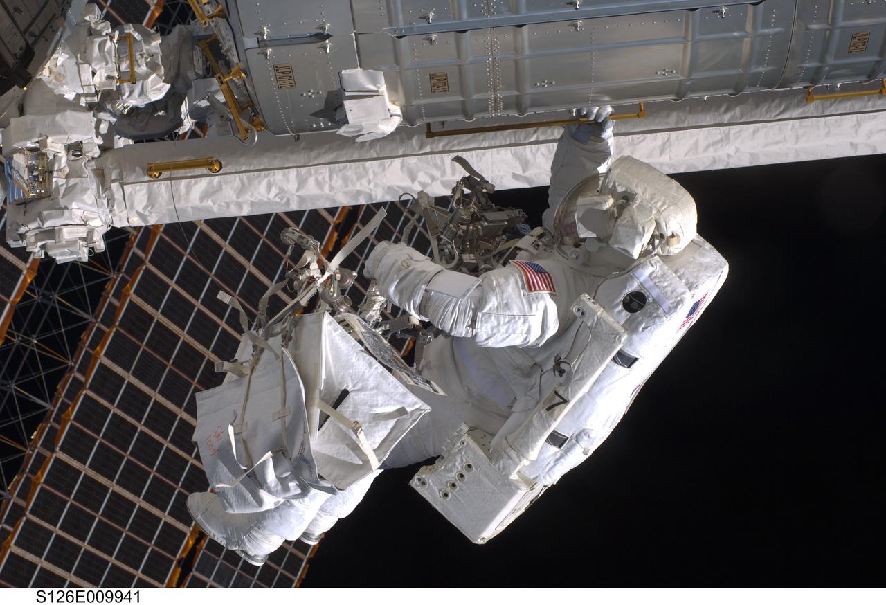
S126-E-009941 (24 Nov. 2008) --- Astronaut Steve Bowen, STS-126 mission specialist, participates in the mission's fourth and final scheduled session of extravehicular activity (EVA) as construction and maintenance continue on the International Space Station. During the six-hour, seven-minute spacewalk, Bowen and astronaut Shane Kimbrough (out of frame), mission specialist, completed the lubrication of the port Solar Alpha Rotary Joints (SARJ) as well as other station assembly tasks. Bowen returned to the starboard SARJ to install the final trundle bearing assembly, retracted a berthing mechanism latch on the Japanese Kibo Laboratory and reinstalled its thermal cover. Bowen also installed a video camera on the Port 1 truss and attached a Global Positioning System antenna on the Japanese Experiment Module Pressurized Section.
VANDENBERG AIR FORCE BASE, Calif. -- On Launch Complex 576-E at Vandenberg Air Force Base in California, Orbital Sciences Engineer Jose Castillo maneuvers the bucket truck into position over the fairing access door on NASA's Orbiting Carbon Observatory, or OCO. On the top of the OCO fairing is the shadow of Glenn Weigle of Orbital Satellite Systems Group, on a bucket out of camera range at left, who is waiting to move in and inspect the GN2 instrument purge flow. OCO will collect precise global measurements of carbon dioxide (CO2) in the Earth's atmosphere. Scientists will analyze OCO data to improve our understanding of the natural processes and human activities that regulate the abundance and distribution of this important greenhouse gas. Photo credit: NASA/Richard Nielsen, KSC
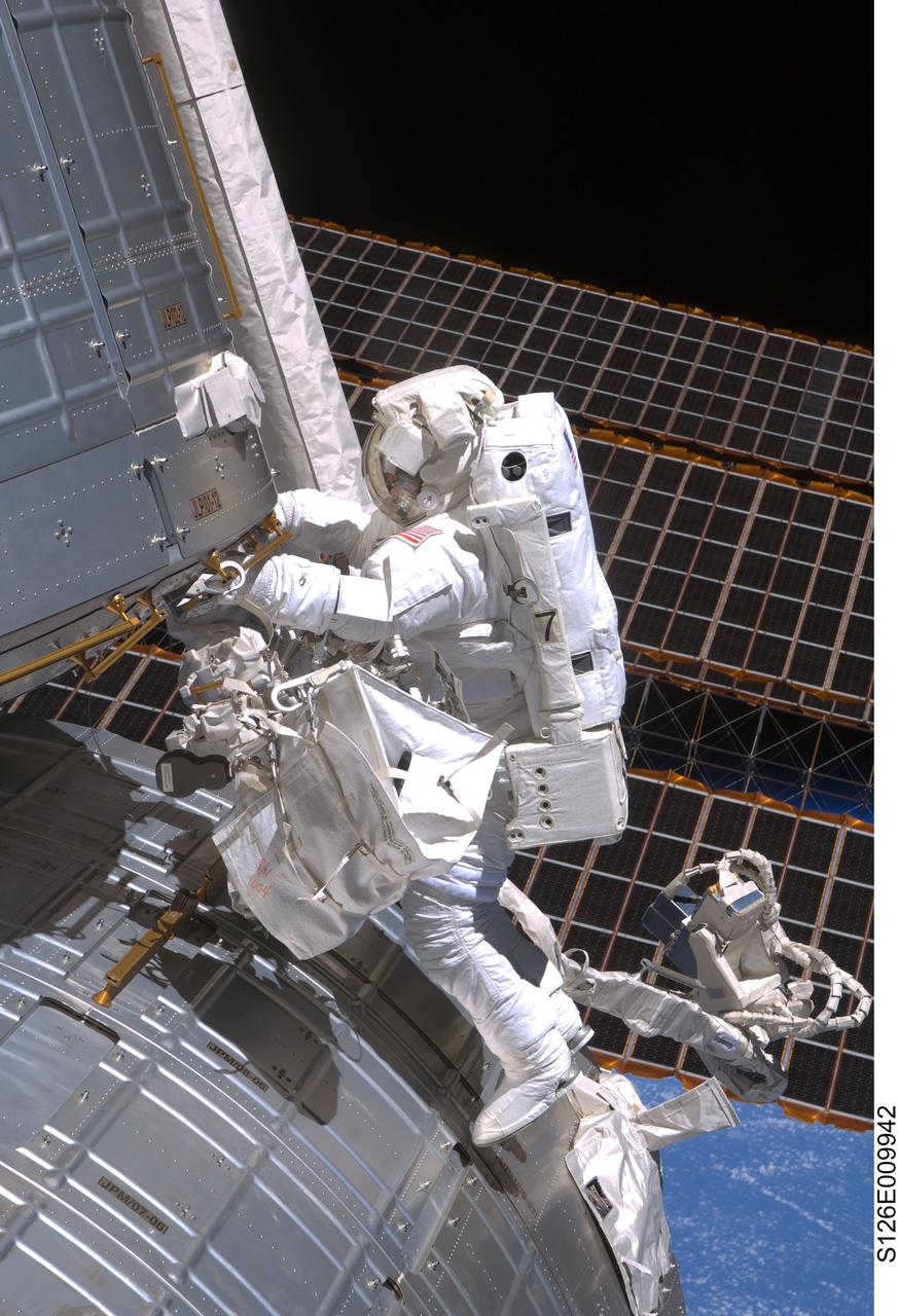
S126-E-009942 (24 Nov. 2008) --- Astronaut Steve Bowen, STS-126 mission specialist, participates in the mission's fourth and final scheduled session of extravehicular activity (EVA) as construction and maintenance continue on the International Space Station. During the six-hour, seven-minute spacewalk, Bowen and astronaut Shane Kimbrough (out of frame), mission specialist, completed the lubrication of the port Solar Alpha Rotary Joints (SARJ) as well as other station assembly tasks. Bowen returned to the starboard SARJ to install the final trundle bearing assembly, retracted a berthing mechanism latch on the Japanese Kibo Laboratory and reinstalled its thermal cover. Bowen also installed a video camera on the Port 1 truss and attached a Global Positioning System antenna on the Japanese Experiment Module Pressurized Section.

KENNEDY SPACE CENTER, FLA. - Technicians monitor the fairing enclosing New Horizons as it is positioned atop a Lockheed Martin Atlas V launch vehicle in the Vertical Integration Facility at Complex 41 on Cape Canaveral Air Force Station. New Horizons carries seven scientific instruments that will characterize the global geology and geomorphology of Pluto and its moon Charon, map their surface compositions and temperatures, and examine Pluto's complex atmosphere. After that, flybys of Kuiper Belt objects from even farther in the solar system may be undertaken in an extended mission. New Horizons is the first mission in NASA's New Frontiers program of medium-class planetary missions. The spacecraft, designed for NASA by the Johns Hopkins University Applied Physics Laboratory in Laurel, Md., will launch aboard a Lockheed Martin Atlas V rocket and fly by Pluto and Charon as early as summer 2015.
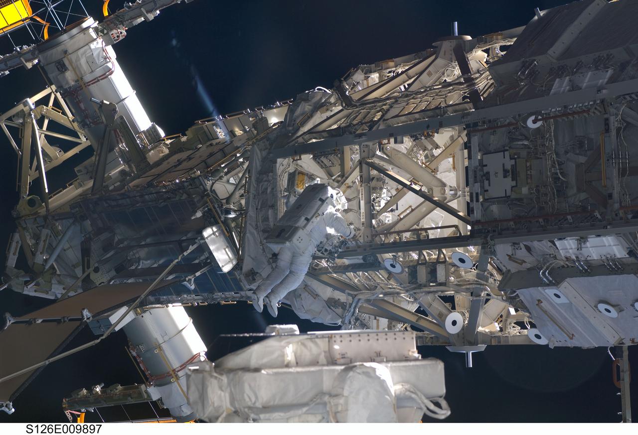
S126-E-009897 (24 Nov. 2008) --- Astronaut Steve Bowen, STS-126 mission specialist, participates in the mission's fourth and final scheduled session of extravehicular activity (EVA) as construction and maintenance continue on the International Space Station. During the six-hour, seven-minute spacewalk, Bowen and astronaut Shane Kimbrough (out of frame), mission specialist, completed the lubrication of the port Solar Alpha Rotary Joints (SARJ) as well as other station assembly tasks. Bowen returned to the starboard SARJ to install the final trundle bearing assembly, retracted a berthing mechanism latch on the Japanese Kibo Laboratory and reinstalled its thermal cover. Bowen also installed a video camera on the Port 1 truss and attached a Global Positioning System antenna on the Japanese Experiment Module Pressurized Section.
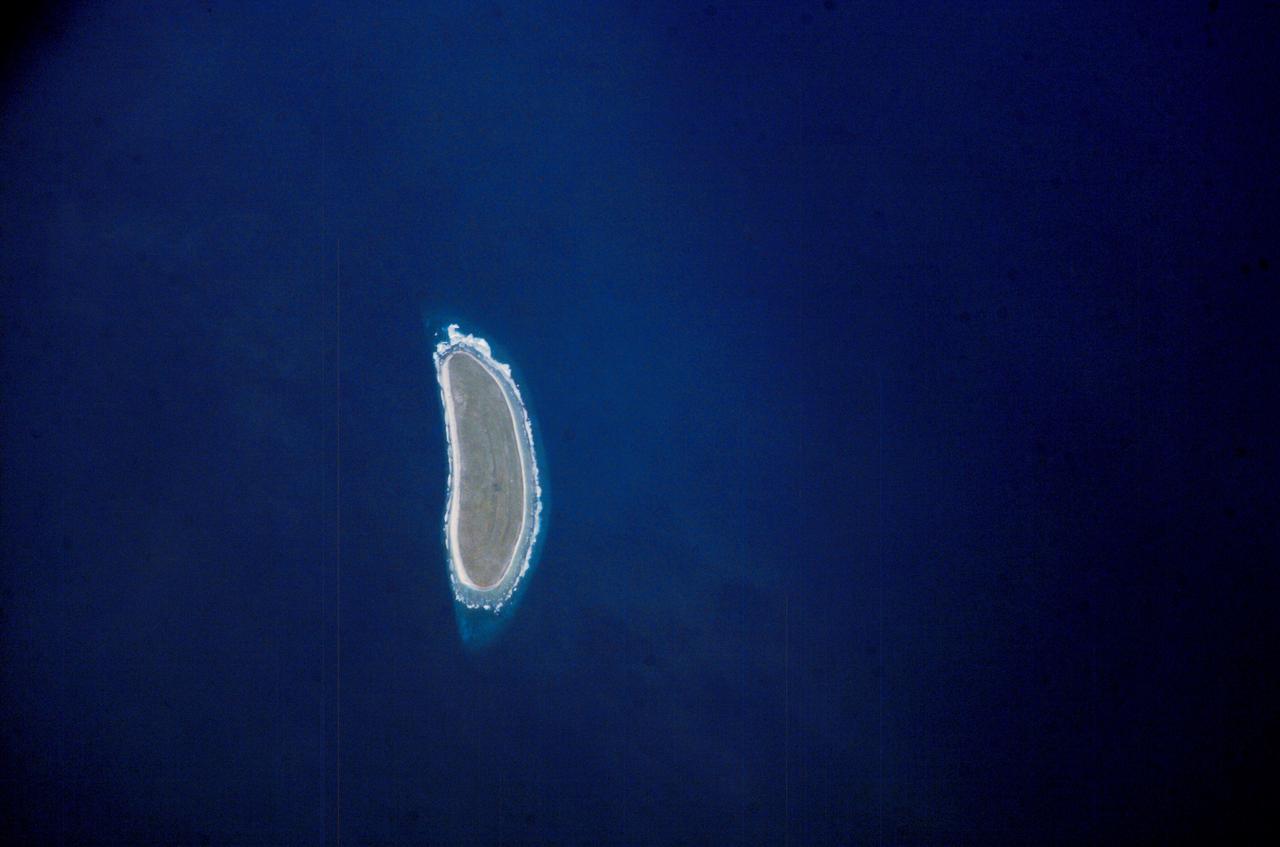
ISS010-E-09287 (3 December 2004) --- Howland Island, Oceania is featured in this digital image photographed by an Expedition 10 crewmember on the International Space Station (ISS). Howland Island is a United States possession located in the north Pacific between Australia and the Hawaiian Islands. Prior to 1890, organic nitrate (guano) was mined from the island by both the United States and the British. This tiny island is currently part of the US National Wildlife Refuge system, and provides nesting areas and forage for a variety of birds and marine wildlife. The island is composed of coral fragments and is surrounded by an active fringing reef. White breakers encircling the island indicate the position of the reef. Astronauts aboard the Space Station photograph numerous reefs around the world as part of a global mapping and monitoring program. High-resolution images such as this one are used to update geographic maps of reefs and islands, assess the health of reef ecosystems, and calculate bathymetry of the surrounding ocean bottom.
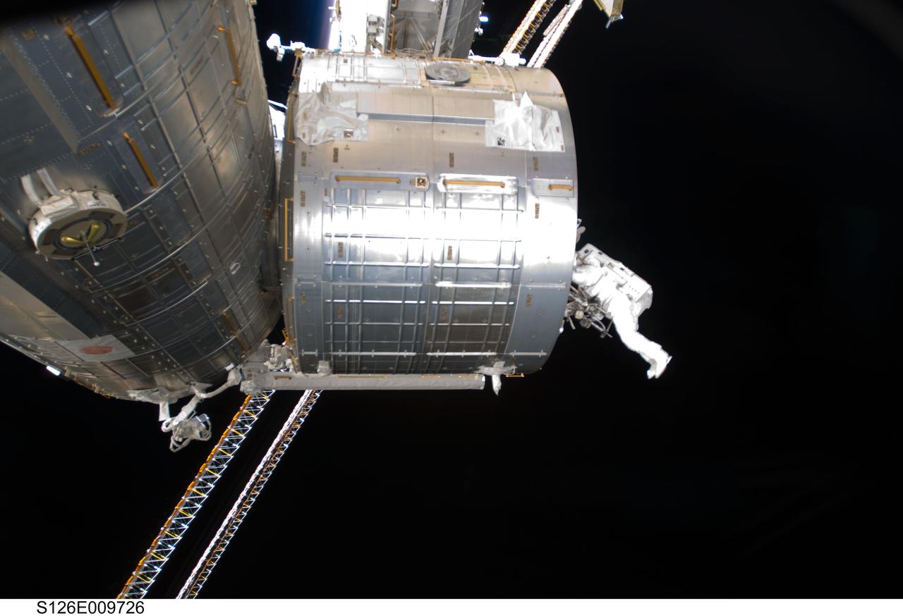
S126-E-009726 (24 Nov. 2008) --- Astronaut Steve Bowen, STS-126 mission specialist, participates in the mission's fourth and final scheduled session of extravehicular activity (EVA) as construction and maintenance continue on the International Space Station. During the six-hour, seven-minute spacewalk, Bowen and astronaut Shane Kimbrough (out of frame), mission specialist, completed the lubrication of the port Solar Alpha Rotary Joints (SARJ) as well as other station assembly tasks. Bowen returned to the starboard SARJ to install the final trundle bearing assembly, retracted a berthing mechanism latch on the Japanese Kibo Laboratory and reinstalled its thermal cover. Bowen also installed a video camera on the Port 1 truss and attached a Global Positioning System antenna on the Japanese Experiment Module Pressurized Section.
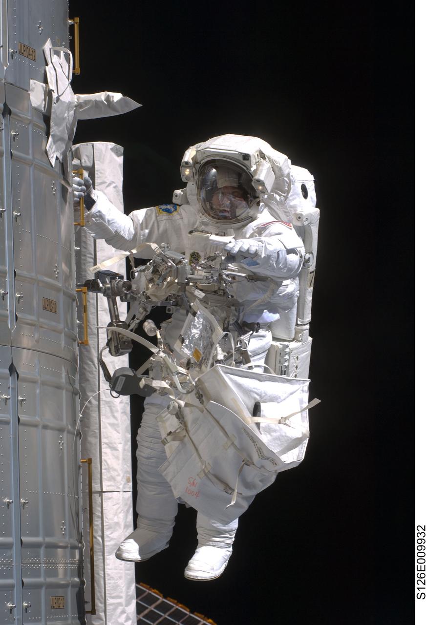
S126-E-009932 (24 Nov. 2008) --- Astronaut Steve Bowen, STS-126 mission specialist, participates in the mission's fourth and final scheduled session of extravehicular activity (EVA) as construction and maintenance continue on the International Space Station. During the six-hour, seven-minute spacewalk, Bowen and astronaut Shane Kimbrough (out of frame), mission specialist, completed the lubrication of the port Solar Alpha Rotary Joints (SARJ) as well as other station assembly tasks. Bowen returned to the starboard SARJ to install the final trundle bearing assembly, retracted a berthing mechanism latch on the Japanese Kibo Laboratory and reinstalled its thermal cover. Bowen also installed a video camera on the Port 1 truss and attached a Global Positioning System antenna on the Japanese Experiment Module Pressurized Section.
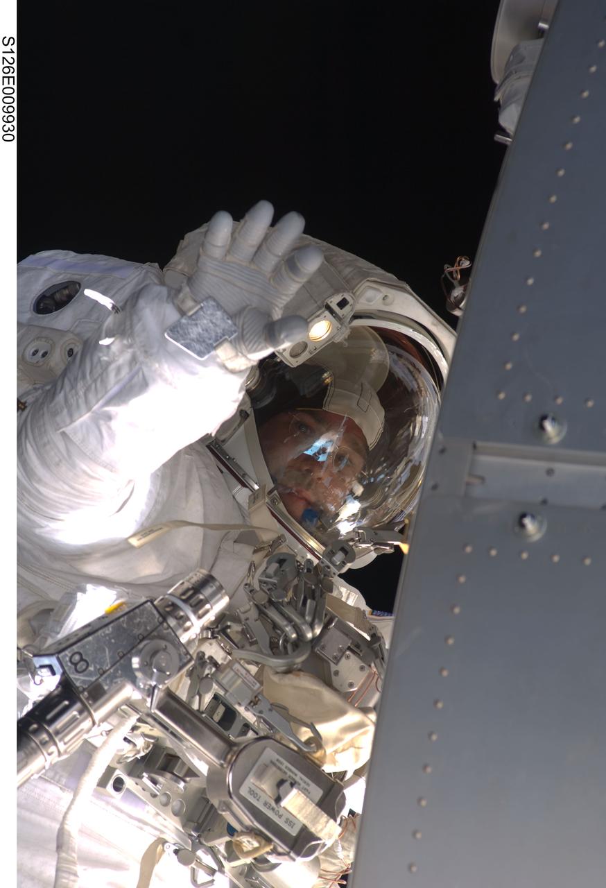
S126-E-009930 (24 Nov. 2008) --- Astronaut Steve Bowen, STS-126 mission specialist, participates in the mission's fourth and final scheduled session of extravehicular activity (EVA) as construction and maintenance continue on the International Space Station. During the six-hour, seven-minute spacewalk, Bowen and astronaut Shane Kimbrough (out of frame), mission specialist, completed the lubrication of the port Solar Alpha Rotary Joints (SARJ) as well as other station assembly tasks. Bowen returned to the starboard SARJ to install the final trundle bearing assembly, retracted a berthing mechanism latch on the Japanese Kibo Laboratory and reinstalled its thermal cover. Bowen also installed a video camera on the Port 1 truss and attached a Global Positioning System antenna on the Japanese Experiment Module Pressurized Section.
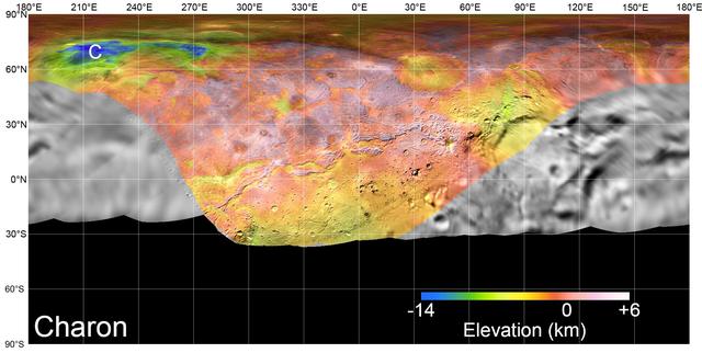
On July 14, 2015, NASA's New Horizons spacecraft made its historic flight through the Pluto system. This detailed, high-quality global mosaic of Pluto's largest moon, Charon, was assembled from nearly all of the highest-resolution images obtained by the Long-Range Reconnaissance Imager (LORRI) and the Multispectral Visible Imaging Camera (MVIC) on New Horizons. The mosaic is the most detailed and comprehensive global view yet of Charon's surface using New Horizons data. It includes topography data of the hemisphere visible to New Horizons during the spacecraft's closest approach. The topography is derived from digital stereo-image mapping tools that measure the parallax -- or the difference in the apparent relative positions -- of features on the surface obtained at different viewing angles during the encounter. Scientists use these parallax displacements of high and low terrain to estimate landform heights. The global mosaic has been overlain with transparent, colorized topography data wherever on the surface stereo data is available. Terrain south of about 30°S was in darkness leading up to and during the flyby, so is shown in black. All feature names on Pluto and Charon are informal. The global mosaic has been overlain with transparent, colorized topography data wherever on their surfaces stereo data is available. Standing out on Charon is the Caleuche Chasma ("C") in the far north, an enormous trough at least 350 kilometers (nearly 220 miles) long, and reaching 14 kilometers (8.5 miles) deep -- more than seven times as deep as the Grand Canyon. https://photojournal.jpl.nasa.gov/catalog/PIA21860
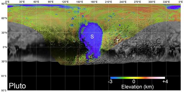
On July 14, 2015, NASA's New Horizons spacecraft made its historic flight through the Pluto system. This detailed, high-quality global mosaic of Pluto was assembled from nearly all of the highest-resolution images obtained by the Long-Range Reconnaissance Imager (LORRI) and the Multispectral Visible Imaging Camera (MVIC) on New Horizons. The mosaic is the most detailed and comprehensive global view yet of Pluto's surface using New Horizons data. It includes topography data of the hemisphere visible to New Horizons during the spacecraft's closest approach. The topography is derived from digital stereo-image mapping tools that measure the parallax -- or the difference in the apparent relative positions -- of features on the surface obtained at different viewing angles during the encounter. Scientists use these parallax displacements of high and low terrain to estimate landform heights. The global mosaic has been overlain with transparent, colorized topography data wherever on the surface stereo data is available. Terrain south of about 30°S was in darkness leading up to and during the flyby, so is shown in black. Examples of large-scale topographic features on Pluto include the vast expanse of very flat, low-elevation nitrogen ice plains of Sputnik Planitia ("P") -- note that all feature names in the Pluto system are informal -- and, on the eastern edge of the encounter hemisphere, the aligned, high-elevation ridges of Tartarus Dorsa ("T") that host the enigmatic bladed terrain, mountains, possible cryovolcanos, canyons, craters and more. https://photojournal.jpl.nasa.gov/catalog/PIA21861
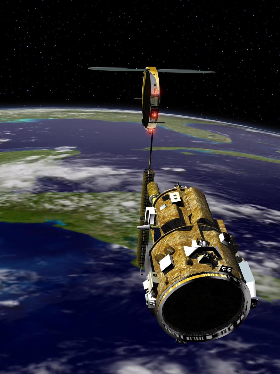
KENNEDY SPACE CENTER, FLA. - An artist’s conception of the autonomous Demonstration for Autonomous Rendezvous (DART) spacecraft as it approaches the Multiple Paths, Beyond-Line-of-Site Communications (MUBLCOM) satellite. NASA is testing the DART as a docking system for next generation vehicles to guide spacecraft carrying cargo or equipment to the International Space Station, or retrieving or servicing satellites in orbit. Before the new system can be implemented on piloted spacecraft, it has to be tested in space. The computer-guided DART is equipped with an Advanced Video Guidance Sensor and a Global Positioning System that can receive signals from other spacecraft to allow DART to move within 330 feet of the target. DART is scheduled to launch from Vandenberg Air Force Base in California no earlier than Oct. 18. It will be released from a Pegasus XL launch vehicle carried aloft by an Orbital Sciences Corporation aircraft. The fourth stage of the Pegasus rocket will remain attached as an integral part of the spacecraft, allowing it to maneuver in space. Once in orbit, DART will race toward the target, the MUBLCOM satellite, for a rendezvous.
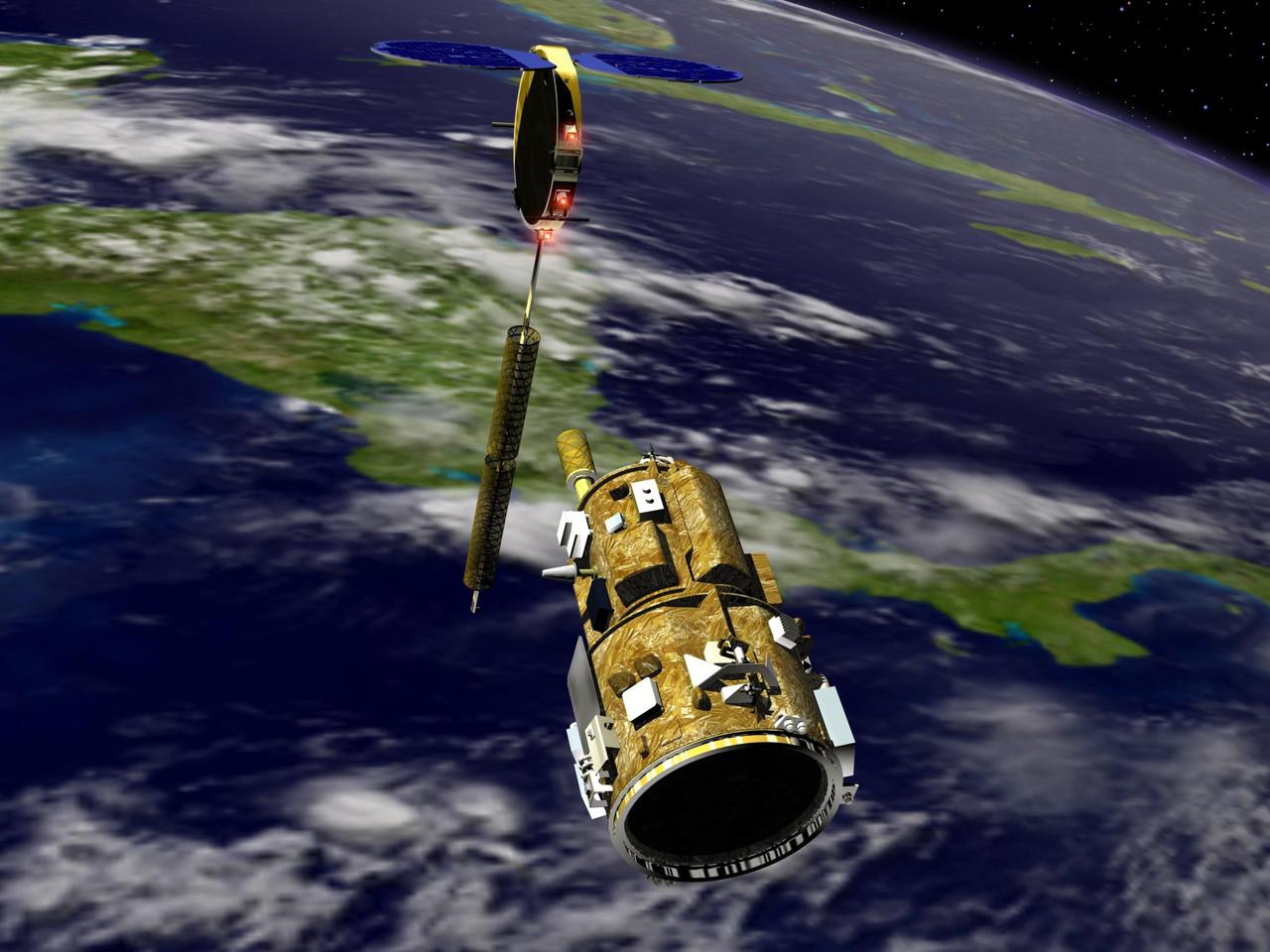
KENNEDY SPACE CENTER, FLA. - An artist’s conception of the autonomous Demonstration for Autonomous Rendezvous (DART) spacecraft as it approaches the Multiple Paths, Beyond-Line-of-Site Communications (MUBLCOM) satellite. NASA is testing the DART as a docking system for next generation vehicles to guide spacecraft carrying cargo or equipment to the International Space Station, or retrieving or servicing satellites in orbit. Before the new system can be implemented on piloted spacecraft, it has to be tested in space. The computer-guided DART is equipped with an Advanced Video Guidance Sensor and a Global Positioning System that can receive signals from other spacecraft to allow DART to move within 330 feet of the target. DART is scheduled to launch from Vandenberg Air Force Base in California no earlier than Oct. 18. It will be released from a Pegasus XL launch vehicle carried aloft by an Orbital Sciences Corporation aircraft. The fourth stage of the Pegasus rocket will remain attached as an integral part of the spacecraft, allowing it to maneuver in space. Once in orbit, DART will race toward the target, the MUBLCOM satellite, for a rendezvous.
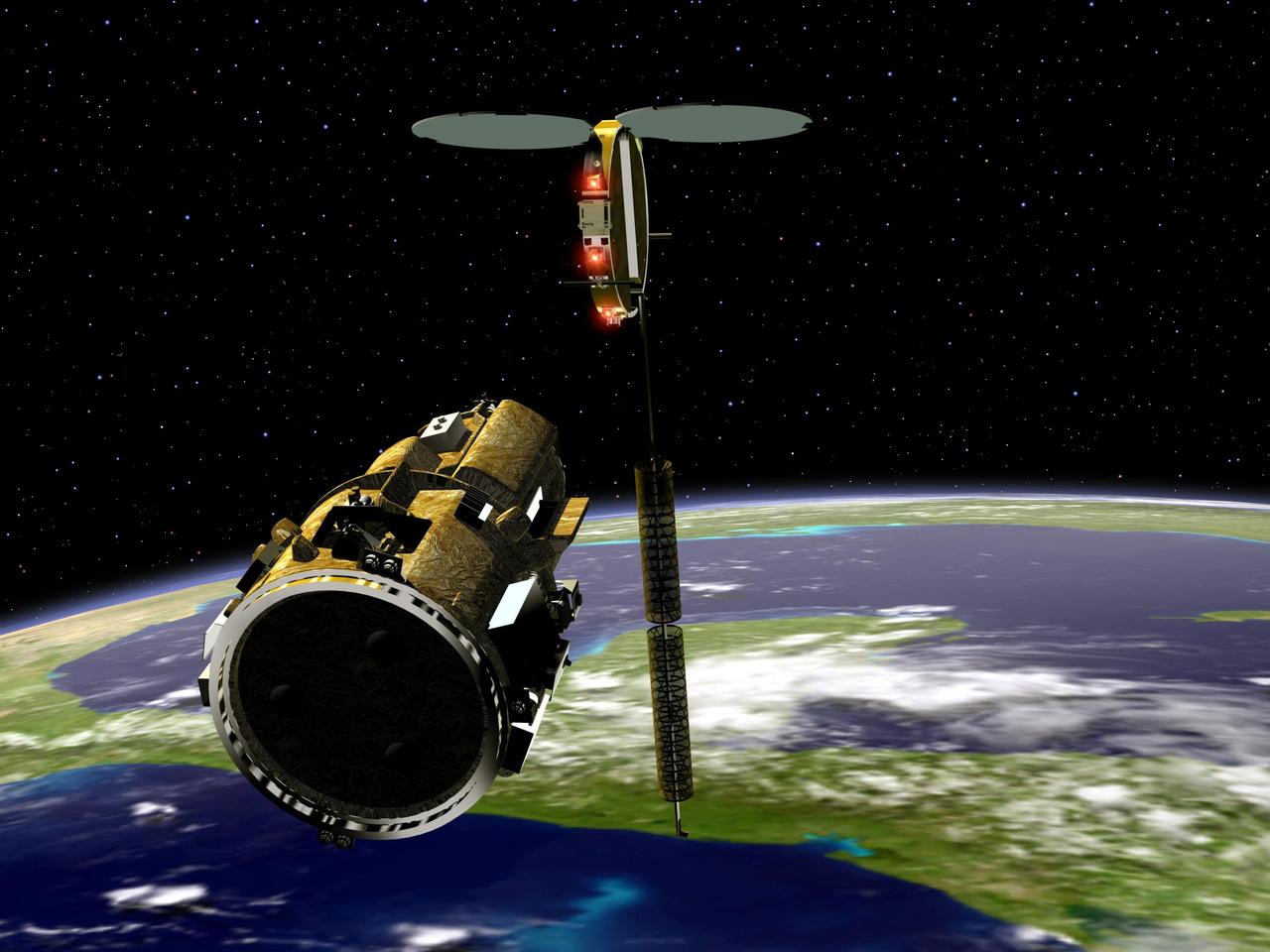
KENNEDY SPACE CENTER, FLA. - An artist’s conception of the autonomous Demonstration for Autonomous Rendezvous (DART) spacecraft as it approaches the Multiple Paths, Beyond-Line-of-Site Communications (MUBLCOM) satellite. NASA is testing the DART as a docking system for next generation vehicles to guide spacecraft carrying cargo or equipment to the International Space Station, or retrieving or servicing satellites in orbit. Before the new system can be implemented on piloted spacecraft, it has to be tested in space. The computer-guided DART is equipped with an Advanced Video Guidance Sensor and a Global Positioning System that can receive signals from other spacecraft to allow DART to move within 330 feet of the target. DART is scheduled to launch from Vandenberg Air Force Base in California no earlier than Oct. 18. It will be released from a Pegasus XL launch vehicle carried aloft by an Orbital Sciences Corporation aircraft. The fourth stage of the Pegasus rocket will remain attached as an integral part of the spacecraft, allowing it to maneuver in space. Once in orbit, DART will race toward the target, the MUBLCOM satellite, for a rendezvous.
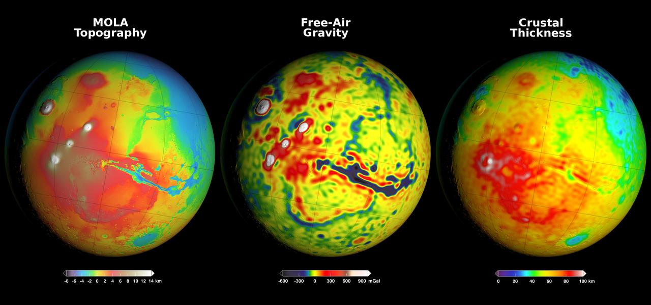
Newly detailed mapping of local variations in Mars' gravitational pull on orbiters (center), combined with topographical mapping of the planet's mountains and valleys (left) yields the best-yet mapping of Mars' crustal thickness (right). These three views of global mapping are centered at 90 degrees west longitude, showing portions of the planet that include tall volcanoes on the left and the deep Valles Marineris canyon system just right of center. Additional views of these global maps are available at http://svs.gsfc.nasa.gov/goto?4436. The new map of Mars' gravity (center) results from analysis of the planet's gravitational effects on orbiters passing over each location on the globe. The data come from many years of using NASA's Deep Space Network to track positions and velocities of NASA's Mars Global Surveyor, Mars Odyssey and Mars Reconnaissance Orbiter. If Mars were a perfectly smooth sphere of uniform density, the gravity experienced by the spacecraft would be exactly the same everywhere. But like other rocky bodies in the solar system, including Earth, Mars has both a bumpy surface and a lumpy interior. As the spacecraft fly in their orbits, they experience slight variations in gravity caused by both of these irregularities, variations which show up as small changes in the velocity and altitude of the three spacecraft. The "free-air" gravity map presents the results without any adjustment for the known bumpiness of Mars' surface. Local gravitational variations in acceleration are expressed in units called gals or galileos. The color-coding key beneath the center map indicates how colors on the map correspond to mGal (milligal) values. The map on the left shows the known bumpiness, or topography, of the Martian surface, using data from the Mars Orbiter Laser Altimeter (MOLA) instrument on Mars Global Surveyor. Mars has no actual "sea level," but does have a defined zero elevation level. The color-coding key beneath this map indicates how the colors correspond to elevations above or below zero, in kilometers. Analysis that subtracts effects of the surface topography from the free-air gravity mapping, combined with an assumption that crust material has a uniform density, leads to the derived mapping of crustal thickness -- or subsurface "lumpiness" -- on the right. Highs in gravity indicate places where the denser mantle material beneath the crust is closer to the surface, and hence where the crust is thinner. The color-coding key for this map indicates how the colors on the map correspond to the thickness of the crust, in kilometers. http://photojournal.jpl.nasa.gov/catalog/PIA20277
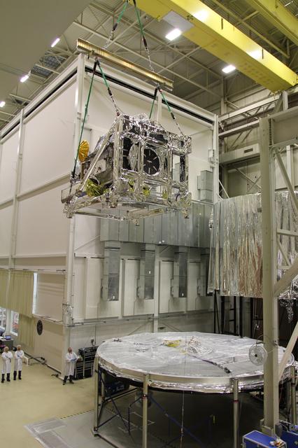
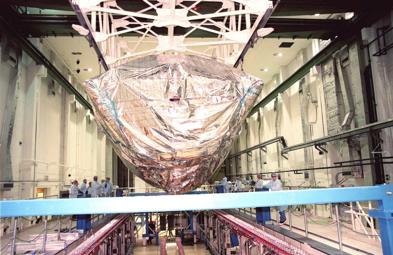
Crane lifting the GPM Core Observatory into position for TVAC testing. Credit: NASA/Goddard The Global Precipitation Measurement (GPM) mission is an international partnership co-led by NASA and the Japan Aerospace Exploration Agency (JAXA) that will provide next-generation global observations of precipitation from space. GPM will study global rain, snow and ice to better understand our climate, weather, and hydrometeorological processes. As of Novermber 2013 the GPM Core Observatory is in the final stages of testing at NASA Goddard Space Flight Center. The satellite will be flown to Japan in the fall of 2013 and launched into orbit on an HII-A rocket in early 2014. For more on the GPM mission, visit <a href="http://gpm.gsfc.nasa.gov/" rel="nofollow">gpm.gsfc.nasa.gov/</a>. <b><a href="http://www.nasa.gov/audience/formedia/features/MP_Photo_Guidelines.html" rel="nofollow">NASA image use policy.</a></b> <b><a href="http://www.nasa.gov/centers/goddard/home/index.html" rel="nofollow">NASA Goddard Space Flight Center</a></b> enables NASA’s mission through four scientific endeavors: Earth Science, Heliophysics, Solar System Exploration, and Astrophysics. Goddard plays a leading role in NASA’s accomplishments by contributing compelling scientific knowledge to advance the Agency’s mission. <b>Follow us on <a href="http://twitter.com/NASA_GoddardPix" rel="nofollow">Twitter</a></b> <b>Like us on <a href="http://www.facebook.com/pages/Greenbelt-MD/NASA-Goddard/395013845897?ref=tsd" rel="nofollow">Facebook</a></b> <b>Find us on <a href="http://instagram.com/nasagoddard?vm=grid" rel="nofollow">Instagram</a></b>
KENNEDY SPACE CENTER, FLA. -- At KSC's Shuttle Landing Facility, workers load the S0 truss segment onto a flatbed trailer for its transfer to the Operations and Checkout Bldg. for processing. The truss arrived at the SLF aboard a "Super Guppy" aircraft from Boeing in Huntington, Calif. During processing in the O&C, the S0 truss will have installed the Canadian Mobile Transporter, power distribution system modules, a heat pipe radiator for cooling, computers, and a pair of rate gyroscopes. Four Global Positioning System antennas are already installed. A 44by 15-foot structure weighing 30,800 pounds when fully outfitted and ready for launch, the truss will be at the center of the ISS 10-truss, girderlike structure that will ultimately extend the length of a football field. Eventually the S0 truss will be attached to the U.S. Lab, "Destiny," which is scheduled to be added to the ISS in April 2000. Later, other trusses will be attached to the S0 on-orbit. The S0 truss is scheduled to be launched in the first quarter of 2001 on mission STS-108
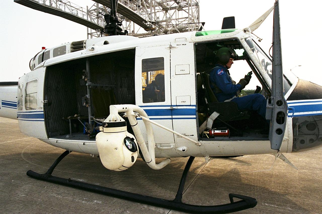
KENNEDY SPACE CENTER, FLA. -- A beach ball-sized infrared camera, part of the Forward Looking Infrared Radar (FLIR), has been mounted on the right siderail of NASA's Huey UH-1 helicopter. A KSC pilot prepares to fly the helicopter, which has also been outfitted with a portable global positioning satellite (GPS) system, to support Florida's Division of Forestry as they fight the brush fires which have been plaguing the state as a result of extremely dry conditions and lightning storms. The FLIR also includes a real-time television monitor and recorder installed inside the helicopter. While the FLIR collects temperature data and images, the GPS system provides the exact coordinates of the fires being observed and transmits the data to the firefighters on the ground. The Kennedy Space Center (KSC) security team routinely uses the FLIR equipment prior to Shuttle launch and landing activities to ensure that the area surrounding the launch pad and runway are clear of unauthorized personnel. KSC's Base Operations Contractor, EG&G Florida, operates the NASA-owned helicopter
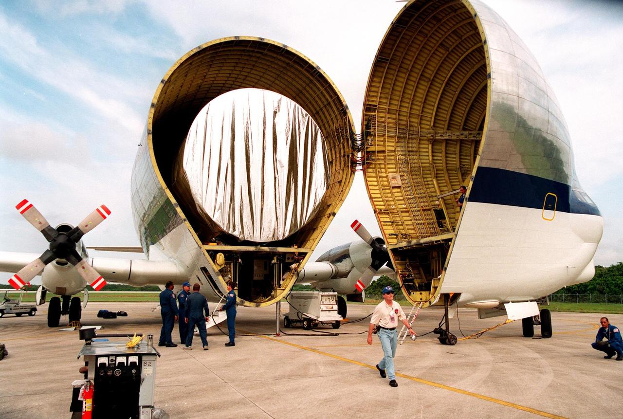
KENNEDY SPACE CENTER, FLA. -- After landing at KSC's Shuttle Landing Facility, the "Super Guppy" transport aircraft opens to reveal its cargo, a S0 (S Zero) truss segment, from Boeing in Huntington Beach, Calif. The truss segment, which will become the backbone of the orbiting International Space Station (ISS), is a 44by 15-foot structure weighing 30,800 pounds when fully outfitted and ready for launch. It will be at the center of the ISS 10-truss, girderlike structure that will ultimately extend the length of a football field. Eventually the S0 truss will be attached to the U.S. Lab, "Destiny," which is scheduled to be added to the ISS in April 2000. Later, other trusses will be attached to the S0 on-orbit. During processing at KSC, the S0 truss will have installed the Canadian Mobile Transporter, power distribution system modules, a heat pipe radiator for cooling, computers, and a pair of rate gyroscopes. Four Global Positioning System antennas are already installed. The S0 truss is scheduled to be launched in the first quarter of 2001 on mission STS-108

Both halves of the United Launch Alliance (ULA) Atlas V payload fairing are moved into position for a fit check at the Astrotech Processing Facility at Vandenberg Space Force Base (VSFB) in California on Aug. 13, 2022, for NASA and the National Oceanic and Atmospheric Administration’s (NOAA) Joint Polar Satellite System-2 (JPSS-2) satellite mission. JPSS-2 is the third satellite in the Joint Polar Satellite System series. It is scheduled to lift off from VSFB on Nov. 1 from Space Launch Complex-3 East. JPSS-2 will scan the globe as it orbits from the North to the South Pole, crossing the equator 14 times a day. From 512 miles above Earth, it will capture data that inform weather forecasts, extreme weather events, and climate change. The Visible Infrared Radiometer Suite instrument will collect imagery for global observations of the land, atmosphere, cryosphere, and oceans. Launching as a secondary payload to JPSS-2 is NASA’s Low-Earth Orbit Flight Test of an Inflatable Decelerator (LOFTID), dedicated to the memory of Bernard Kutter. LOFTID is a demonstration of a hypersonic inflatable aerodynamic decelerator, or aeroshell, technology that could one day help land humans on Mars.
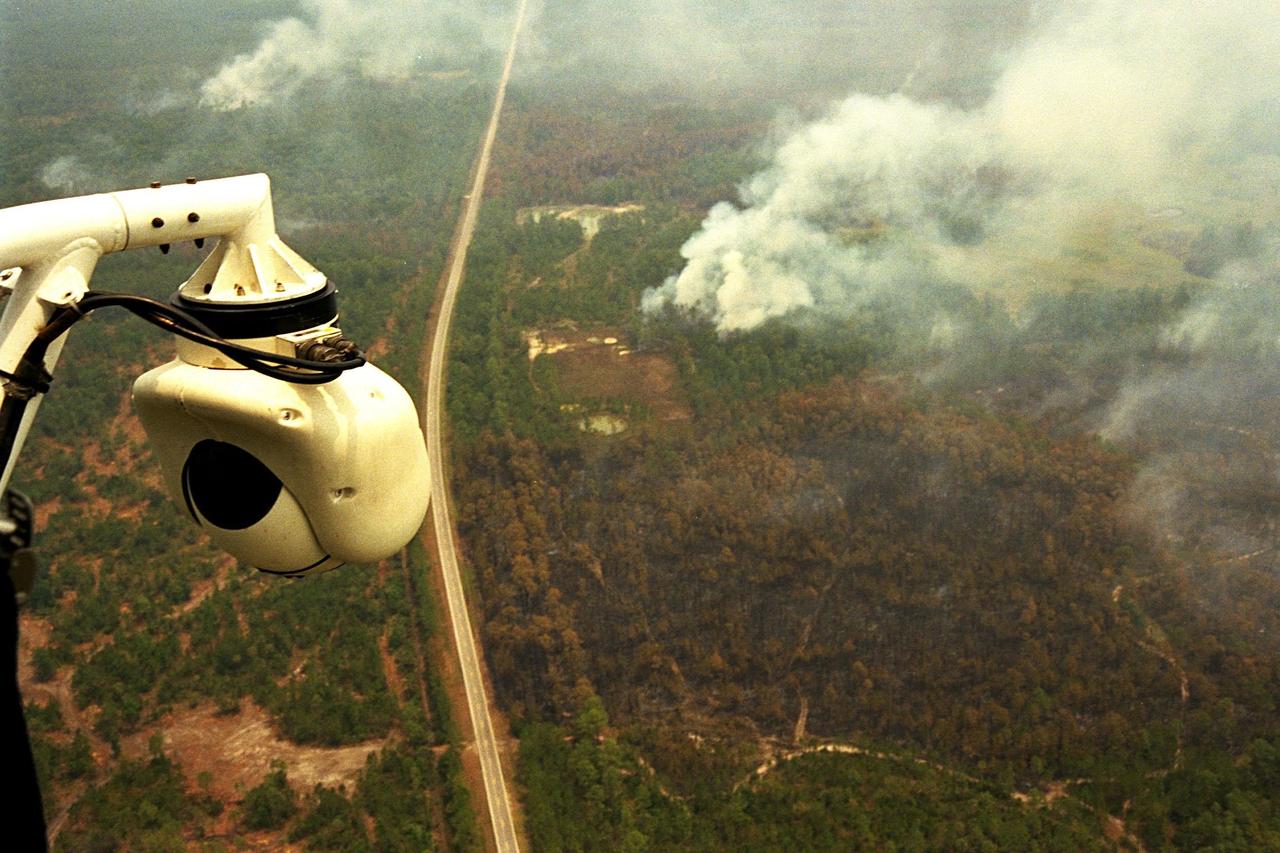
KENNEDY SPACE CENTER, FLA. -- A beach ball-sized infrared camera, part of the Forward Looking Infrared Radar (FLIR), has been mounted on the right siderail of NASA's Huey UH-1 helicopter and is being used to search for fires in Volusia County, Florida. The helicopter has also been outfitted with a portable global positioning satellite (GPS) system to support Florida's Division of Forestry as they fight the brush fires which have been plaguing the state as a result of extremely dry conditions and lightning storms. The FLIR also includes a real-time television monitor and recorder installed inside the helicopter. While the FLIR collects temperature data and images, the GPS system provides the exact coordinates of the fires being observed and transmits the data to the firefighters on the ground. The Kennedy Space Center (KSC) security team routinely uses the FLIR equipment prior to Shuttle launch and landing activities to ensure that the area surrounding the launch pad and runway are clear of unauthorized personnel. KSC's Base Operations Contractor, EG&G Florida, operates the NASA-owned helicopter
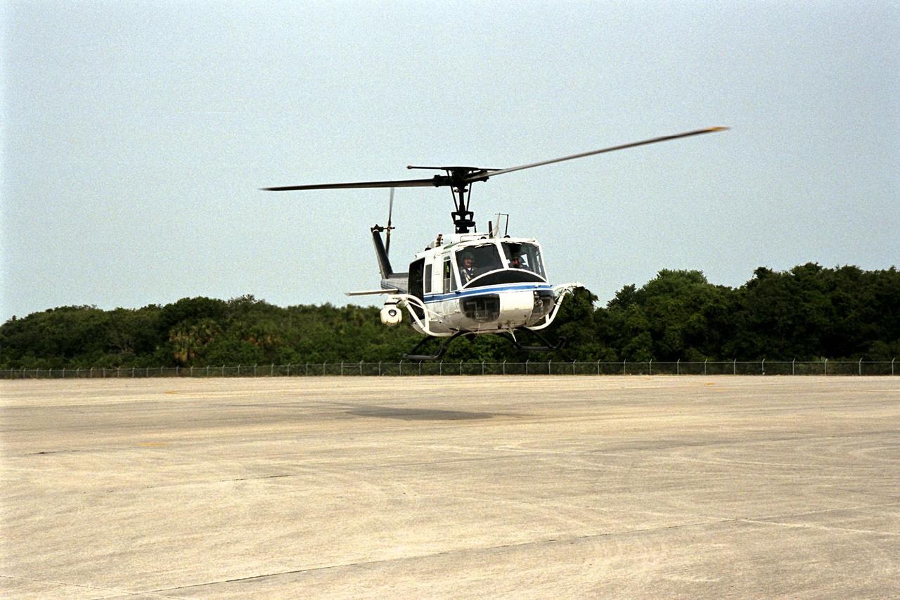
KENNEDY SPACE CENTER, FLA. -- NASA's Huey UH-1 helicopter lands at the Shuttle Landing Facility to pick up Kennedy Space Center (KSC) Security personnel who operate the Forward Looking Infrared Radar (FLIR) installed on board. The helicopter has also been outfitted with a portable global positioning satellite (GPS) system to support Florida's Division of Forestry as they fight the brush fires which have been plaguing the state as a result of extremely dry conditions and lightning storms. The FLIR includes a beach ball-sized infrared camera that is mounted on the helicopter's right siderail and a real-time television monitor and recorder installed inside. While the FLIR collects temperature data and images, the GPS system provides the exact coordinates of the fires being observed and transmits the data to the firefighters on the ground. KSC's security team routinely uses the FLIR equipment prior to Shuttle launch and landing activities to ensure that the area surrounding the launch pad and runway are clear of unauthorized personnel. KSC's Base Operations Contractor, EG&G Florida, operates the NASA-owned helicopter
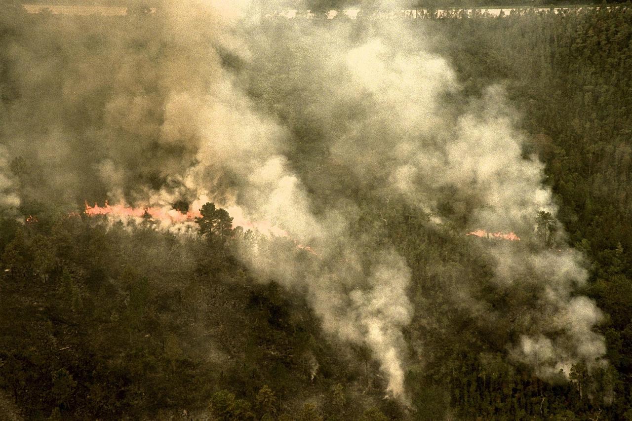
KENNEDY SPACE CENTER, FLA. -- A forest fire burning in Volusia County, Florida, is clearly visible from NASA's Huey UH-1 helicopter. The helicopter has been outfitted with a Forward Looking Infrared Radar (FLIR) and a portable global positioning satellite (GPS) system to support Florida's Division of Forestry as they fight the brush fires which have been plaguing the state as a result of extremely dry conditions and lightning storms. The FLIR includes a beach ball-sized infrared camera that is mounted on the helicopter's right siderail and a real-time television monitor and recorder installed inside. While the FLIR collects temperature data and images, the GPS system provides the exact coordinates of the fires being observed and transmits the data to the firefighters on the ground. The Kennedy Space Center (KSC) security team routinely uses the FLIR equipment prior to Shuttle launch and landing activities to ensure that the area surrounding the launch pad and runway are clear of unauthorized personnel. KSC's Base Operations Contractor, EG&G Florida, operates the NASA-owned helicopter
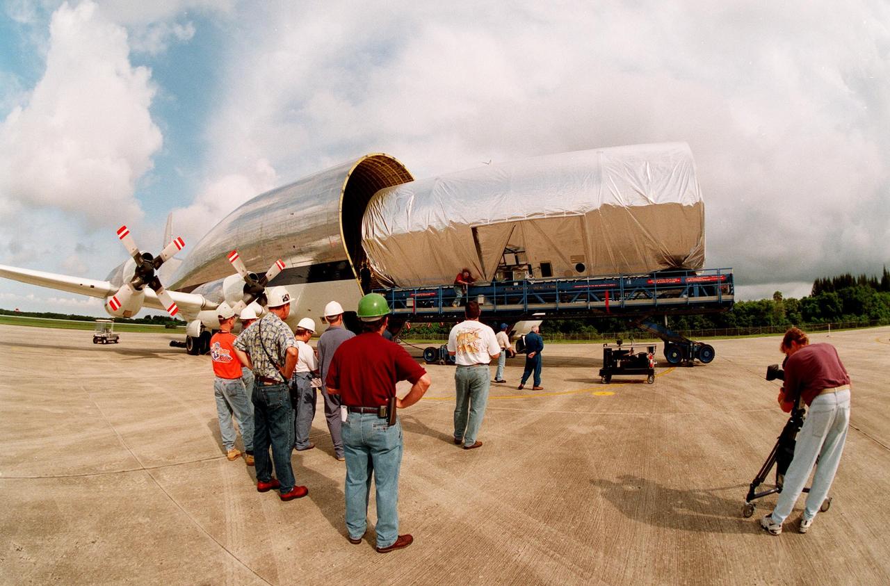
KENNEDY SPACE CENTER, FLA. -- At KSC's Shuttle Landing Facility, workers watch as a S0 (S Zero) truss segment built for the International Space Station (ISS) is moved out of the "Super Guppy" aircraft that brought it to KSC from Boeing in Huntington Beach, Calif. At right a cameraman records the exercise. The truss segment, which will become the backbone of the orbiting ISS, is a 44by 15-foot structure weighing 30,800 pounds when fully outfitted and ready for launch. It will be at the center of the ISS 10-truss, girderlike structure that will ultimately extend the length of a football field. Eventually the S0 truss will be attached to the U.S. Lab, "Destiny," which is scheduled to be added to the ISS in April 2000. Later, other trusses will be attached to the S0 on-orbit. During processing at KSC, the Canadian Mobile Transporter will be installed on the S0 truss, followed by power distribution system modules, a heat pipe radiator for cooling, computers, and a pair of rate gyroscopes. Four Global Positioning System antennas are already installed. The S0 truss is scheduled to be launched in the first quarter of 2001 on mission STS-108
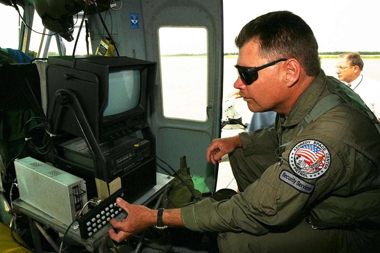
KENNEDY SPACE CENTER, FLA. -- Sgt. Mark Hines, of Kennedy Space Center (KSC) Security, checks out equipment used to operate the Forward Looking Infrared Radar (FLIR) installed on NASA's Huey UH-1 helicopter. The helicopter has also been outfitted with a portable global positioning satellite (GPS) system to support Florida's Division of Forestry as they fight the brush fires which have been plaguing the state as a result of extremely dry conditions and lightning storms. The FLIR includes a beach ball-sized infrared camera that is mounted on the helicopter's right siderail and a real-time television monitor and recorder installed inside. While the FLIR collects temperature data and images, the GPS system provides the exact coordinates of the fires being observed and transmits the data to the firefighters on the ground. KSC's security team routinely uses the FLIR equipment prior to Shuttle launch and landing activities to ensure that the area surrounding the launch pad and runway are clear of unauthorized personnel. KSC's Base Operations Contractor, EG&G Florida, operates the NASA-owned helicopter