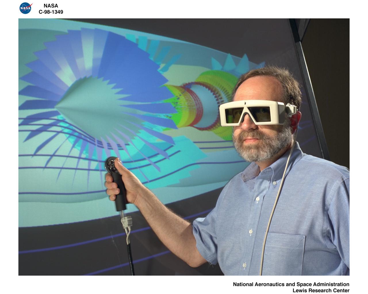
IMMERSADESK II 2 IN GRAPHICS VISUALIZATION LAB
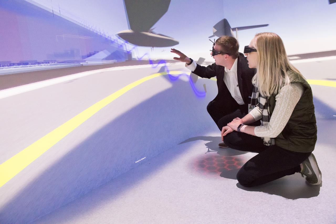
Computer Automatic Virtual Environment, CAVE Tours to Mark the 30th Anniversary of the Graphics and Visualization Lab, GVIS
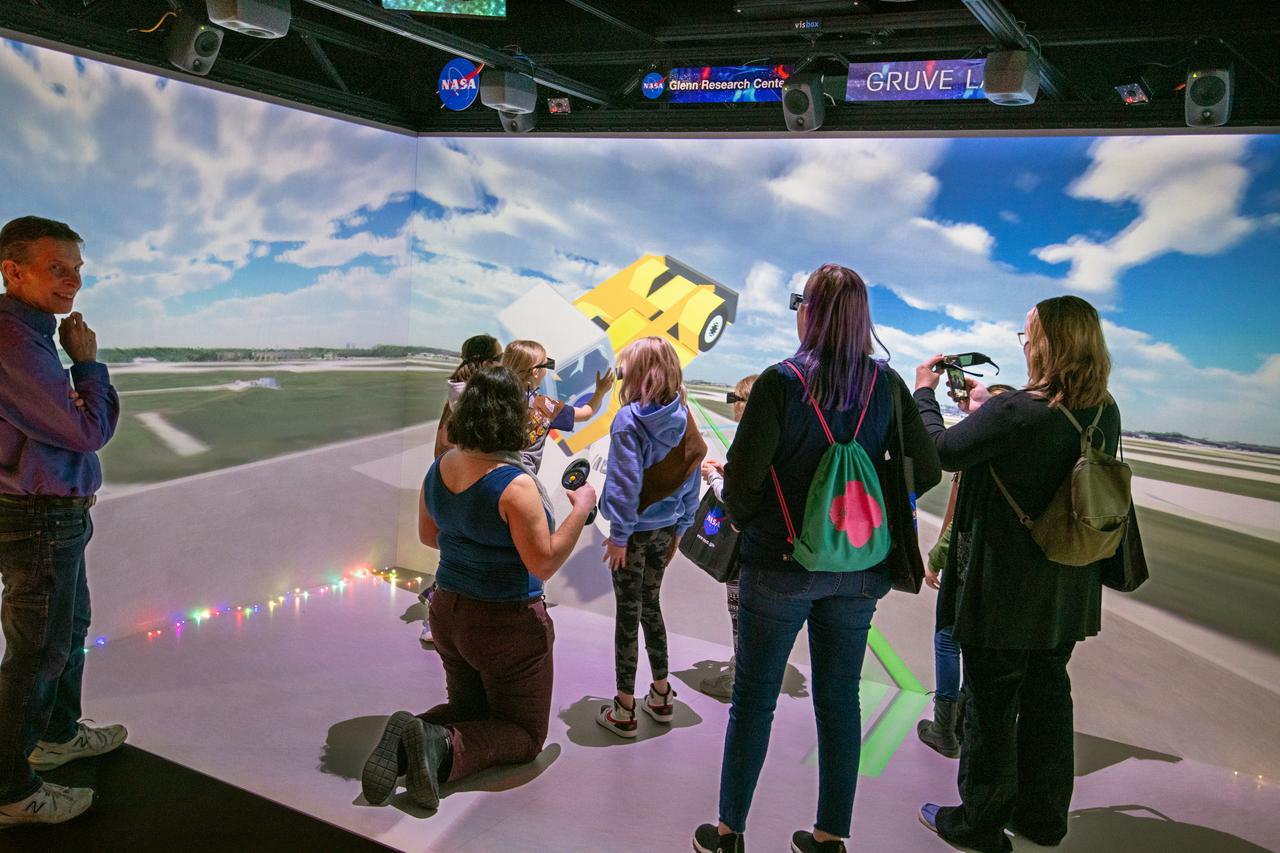
Local area girl scouts competed in a "Girl Scouts to the Moon and Back" essay contest. The essay contest gave the girls scouts a chance to win a Space Science badge that has actually been to space on NASA's Artemis I mission. After the award ceremony the girl scouts got to tour some of the NASA Glenn facilities. Picture is the "cave" at the Graphics and Visualization Lab, also known as the GRUVE Lab. Looking on is Richard Rinehart who is an engineer who works in the GRUVE LAB and creates 3D simulated experiences that demonstrate NASA's technology.
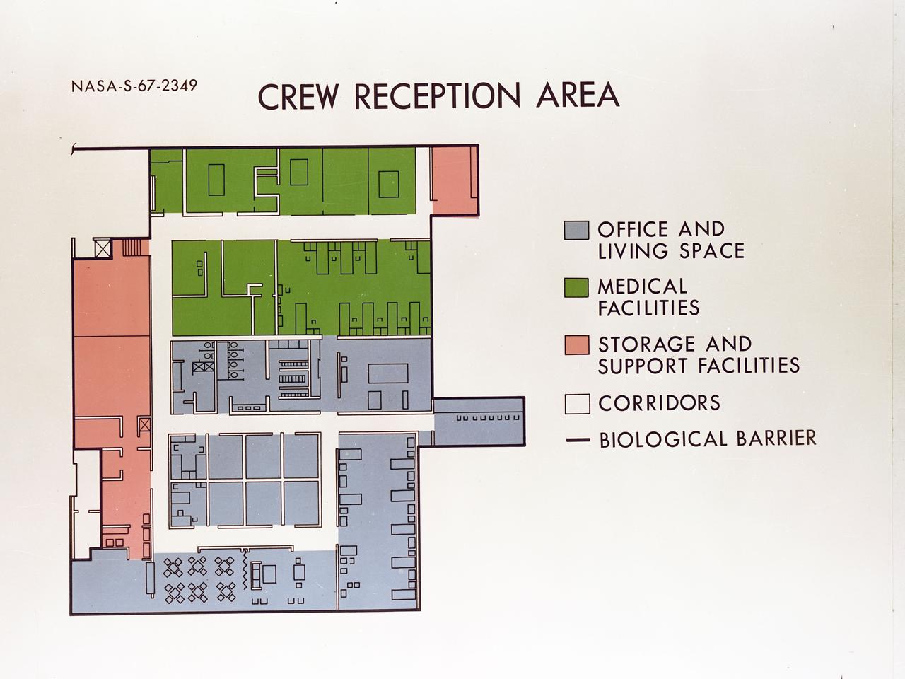
Artist's concept depicting the floor plan of the Crew Reception Area of the Lunar Receiving Laboratory (LRL), bldg 37.
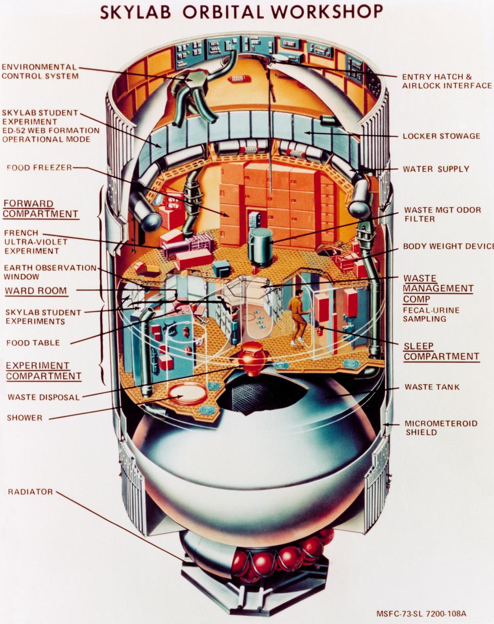
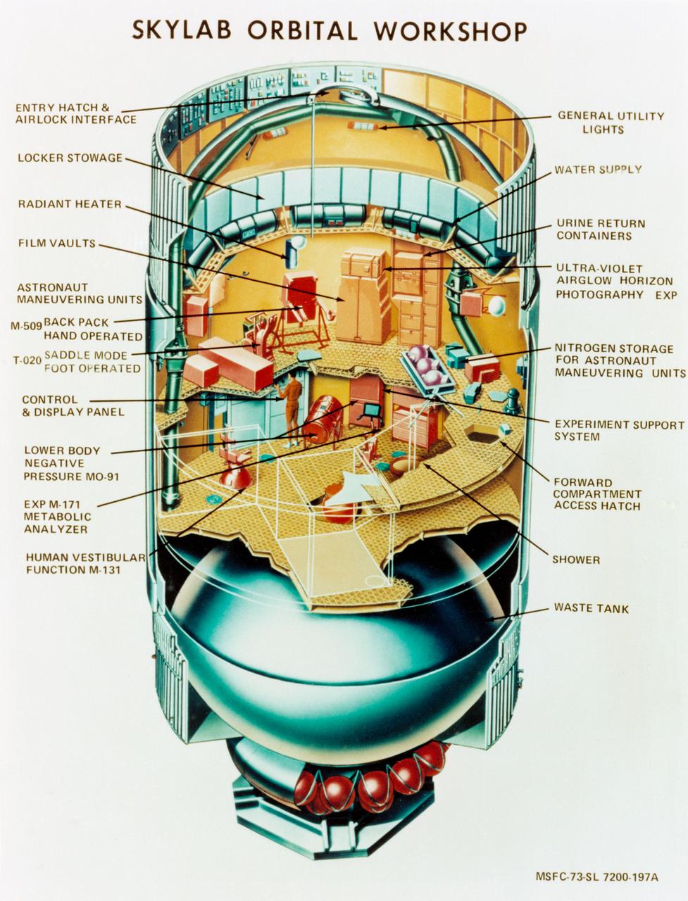
S73-23919 (May 1973) --- An artist's concept illustrating a cutaway view of the Skylab 1 Orbital Workshop (OWS). The OWS is one of the five major components of the Skylab 1 space station cluster which was launched by a Saturn V on May 14, 1973 into Earth orbit. Photo credit: NASA
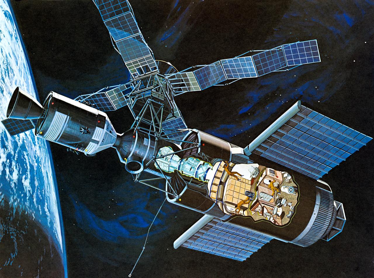
S71-52192 (1971) --- An artist's concept of the Skylab space station cluster in Earth's orbit. The cutaway view shows astronaut activity in the Orbital Workshop (OWS). The Skylab cluster is composed of the OWS, Airlock Module (AM), Multiple Docking Adapter (MDA), Apollo Telescope Mount (ATM), and the Command and Service Module (CSM). Photo credit: NASA
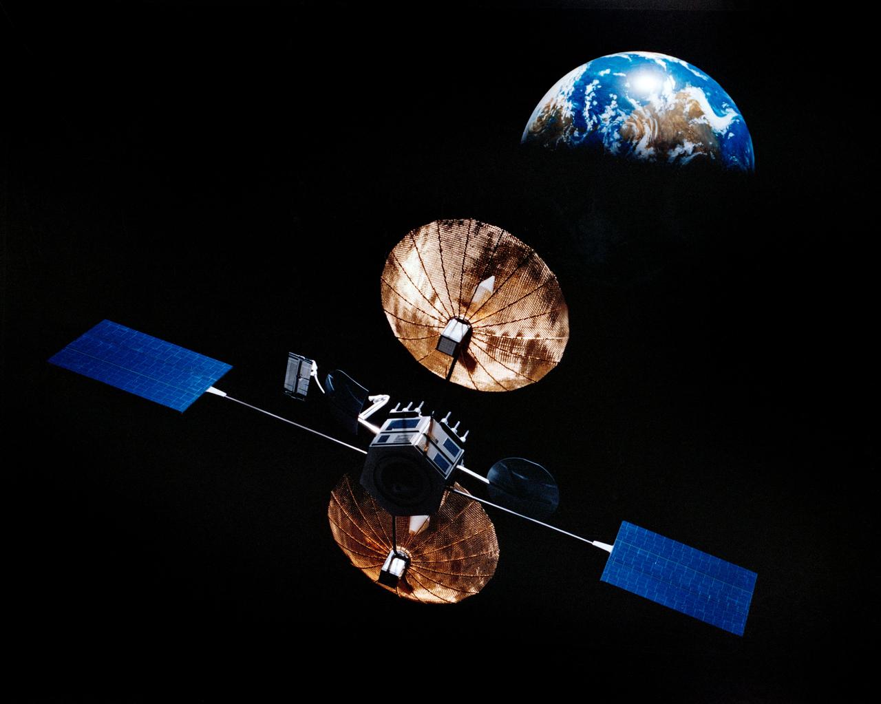
Artist concept of satellite with solar panels deployed in orbit above the earth.
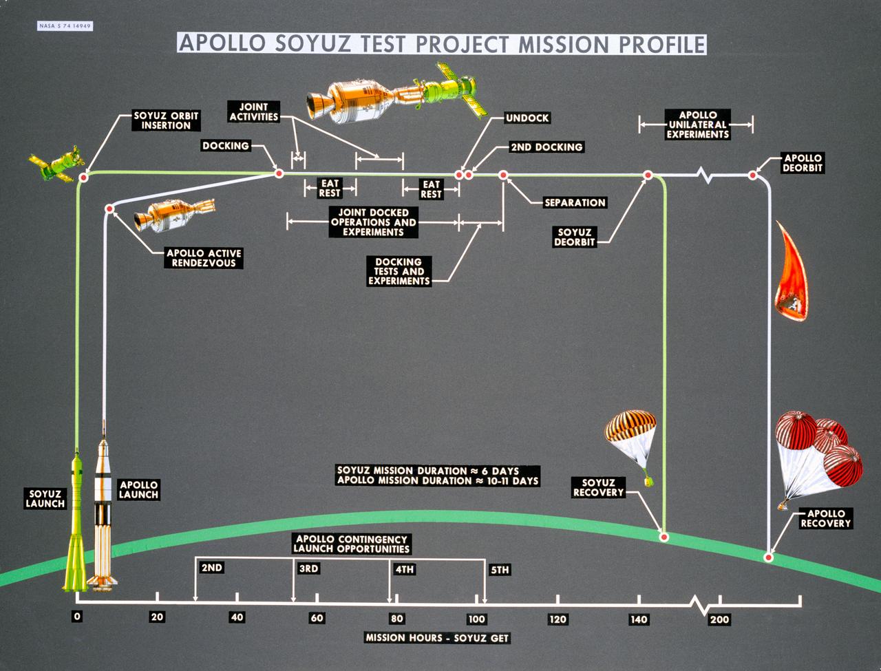
S74-14949 (October 1974) --- Artist?s drawings and call-outs depict phases of the joint U.S.-USSR Apollo-Soyuz Test Project, an Earth-orbital mission which will feature rendezvous and docking of the respective spacecraft of the two nations. ASTP crewmen for the USSR include Aleksey A. Leonov and Valeriy N. Kubasov. The astronaut team includes astronauts Thomas P. Stafford, Vance D. Brand and Donald K. Slayton. The mission is scheduled to take place in summer 1975.
S73-23918 (May 1973) --- An artist's concept illustrating a cutaway view of the Skylab 1 Orbital Workshop (OWS). The OWS is one of the five major components of the Skylab 1 space station cluster which was launched by a Saturn V on May 14, 1973 into Earth orbit. Photo credit: NASA
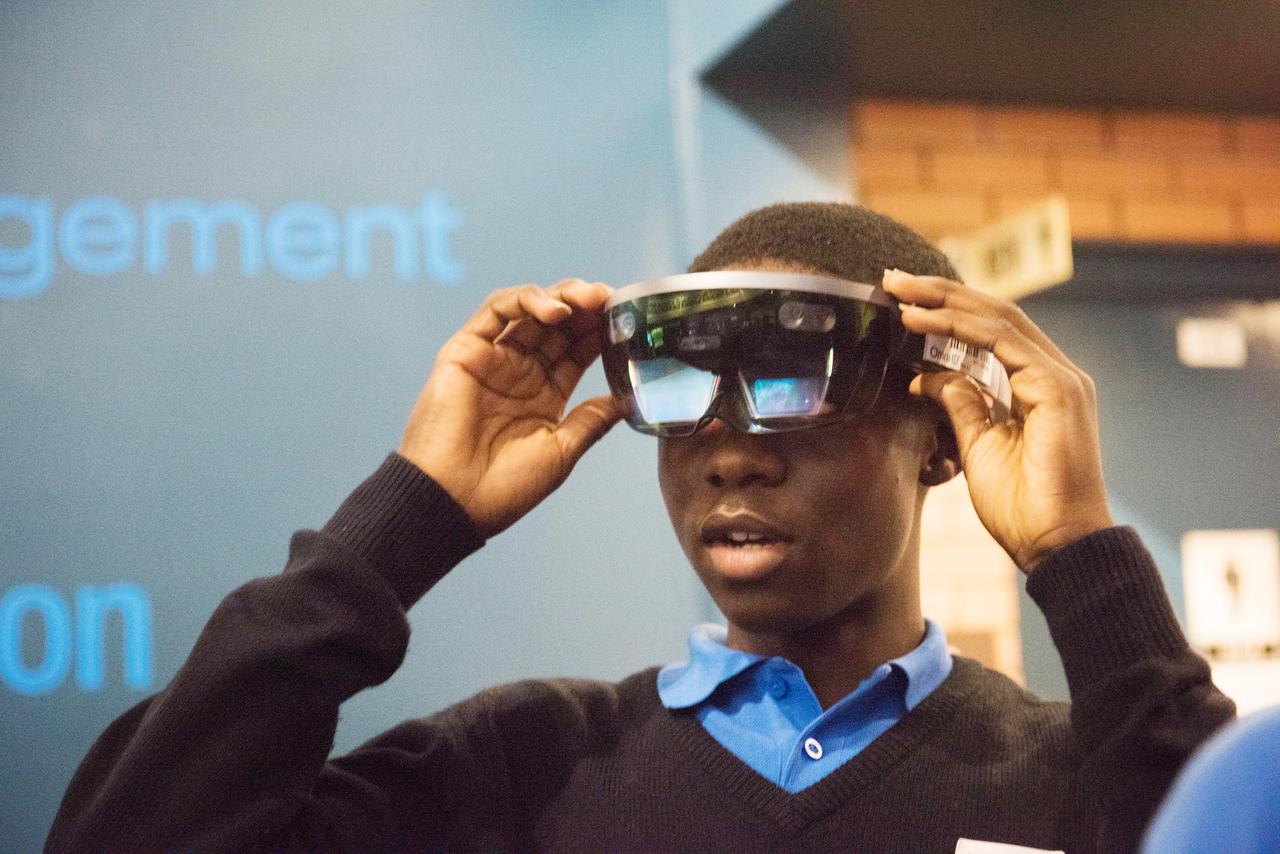
During Avaiation Day, 2018, a Participant uses a Microsoft HoloLens Virtual Reality Headset to view a NASA Created Immersive Visualization
![KENNEDY SPACE CENTER, FLA. - These towers are part of one of the world’s highest performing visual film analysis systems, developed to review and analyze previous shuttle flight data in preparation for the shuttle fleet’s return to flight. The system is being used today for another purpose. NASA has permitted its use in helping to analyze a film that shows a recent kidnapping in progress in Florida. Developed by NASA, United Space Alliance (USA) and Silicon Graphics Inc., the system allows multiple-person collaboration, highly detailed manipulation and evaluation of specific imagery. The system is housed in the Image Analysis Facility inside the Vehicle Assembly Building. [Photo taken Aug. 15, 2003, courtesy of Terry Wallace, SGI ]](https://images-assets.nasa.gov/image/KSC-04pd0152/KSC-04pd0152~medium.jpg)
KENNEDY SPACE CENTER, FLA. - These towers are part of one of the world’s highest performing visual film analysis systems, developed to review and analyze previous shuttle flight data in preparation for the shuttle fleet’s return to flight. The system is being used today for another purpose. NASA has permitted its use in helping to analyze a film that shows a recent kidnapping in progress in Florida. Developed by NASA, United Space Alliance (USA) and Silicon Graphics Inc., the system allows multiple-person collaboration, highly detailed manipulation and evaluation of specific imagery. The system is housed in the Image Analysis Facility inside the Vehicle Assembly Building. [Photo taken Aug. 15, 2003, courtesy of Terry Wallace, SGI ]
![KENNEDY SPACE CENTER, FLA. - One of the world’s highest performing visual film analysis systems, developed to review and analyze previous shuttle flight data (shown here) in preparation for the shuttle fleet’s return to flight, is being used today for another purpose. NASA has permitted its use in helping to analyze a film that shows a recent kidnapping in progress in Florida. The system, developed by NASA, United Space Alliance (USA) and Silicon Graphics Inc., allows multiple-person collaboration, highly detailed manipulation and evaluation of specific imagery. The system is housed in the Image Analysis Facility inside the Vehicle Assembly Building. [Photo taken Aug. 15, 2003, courtesy of Terry Wallace, SGI ]](https://images-assets.nasa.gov/image/KSC-04pd0150/KSC-04pd0150~medium.jpg)
KENNEDY SPACE CENTER, FLA. - One of the world’s highest performing visual film analysis systems, developed to review and analyze previous shuttle flight data (shown here) in preparation for the shuttle fleet’s return to flight, is being used today for another purpose. NASA has permitted its use in helping to analyze a film that shows a recent kidnapping in progress in Florida. The system, developed by NASA, United Space Alliance (USA) and Silicon Graphics Inc., allows multiple-person collaboration, highly detailed manipulation and evaluation of specific imagery. The system is housed in the Image Analysis Facility inside the Vehicle Assembly Building. [Photo taken Aug. 15, 2003, courtesy of Terry Wallace, SGI ]
![KENNEDY SPACE CENTER, FLA. - One of the world’s highest performing visual film analysis systems, developed to review and analyze previous shuttle flight data (shown here) in preparation for the shuttle fleet’s return to flight, is being used today for another purpose. NASA has permitted its use in helping to analyze a film that shows a recent kidnapping in progress in Florida. The system, developed by NASA, United Space Alliance (USA) and Silicon Graphics Inc., allows multiple-person collaboration, highly detailed manipulation and evaluation of specific imagery. The system is housed in the Image Analysis Facility inside the Vehicle Assembly Building. [Photo taken Aug. 15, 2003, courtesy of Terry Wallace, SGI ]](https://images-assets.nasa.gov/image/KSC-04pd0151/KSC-04pd0151~medium.jpg)
KENNEDY SPACE CENTER, FLA. - One of the world’s highest performing visual film analysis systems, developed to review and analyze previous shuttle flight data (shown here) in preparation for the shuttle fleet’s return to flight, is being used today for another purpose. NASA has permitted its use in helping to analyze a film that shows a recent kidnapping in progress in Florida. The system, developed by NASA, United Space Alliance (USA) and Silicon Graphics Inc., allows multiple-person collaboration, highly detailed manipulation and evaluation of specific imagery. The system is housed in the Image Analysis Facility inside the Vehicle Assembly Building. [Photo taken Aug. 15, 2003, courtesy of Terry Wallace, SGI ]
![KENNEDY SPACE CENTER, FLA. - One of the world’s highest performing visual film analysis systems, developed to review and analyze previous shuttle flight data (shown here) in preparation for the shuttle fleet’s return to flight, is being used today for another purpose. NASA has permitted its use in helping to analyze a film that shows a recent kidnapping in progress in Florida. The system, developed by NASA, United Space Alliance (USA) and Silicon Graphics Inc., allows multiple-person collaboration, highly detailed manipulation and evaluation of specific imagery. The system is housed in the Image Analysis Facility inside the Vehicle Assembly Building. [Photo taken Aug. 15, 2003, courtesy of Terry Wallace, SGI ]](https://images-assets.nasa.gov/image/KSC-04pd0154/KSC-04pd0154~medium.jpg)
KENNEDY SPACE CENTER, FLA. - One of the world’s highest performing visual film analysis systems, developed to review and analyze previous shuttle flight data (shown here) in preparation for the shuttle fleet’s return to flight, is being used today for another purpose. NASA has permitted its use in helping to analyze a film that shows a recent kidnapping in progress in Florida. The system, developed by NASA, United Space Alliance (USA) and Silicon Graphics Inc., allows multiple-person collaboration, highly detailed manipulation and evaluation of specific imagery. The system is housed in the Image Analysis Facility inside the Vehicle Assembly Building. [Photo taken Aug. 15, 2003, courtesy of Terry Wallace, SGI ]
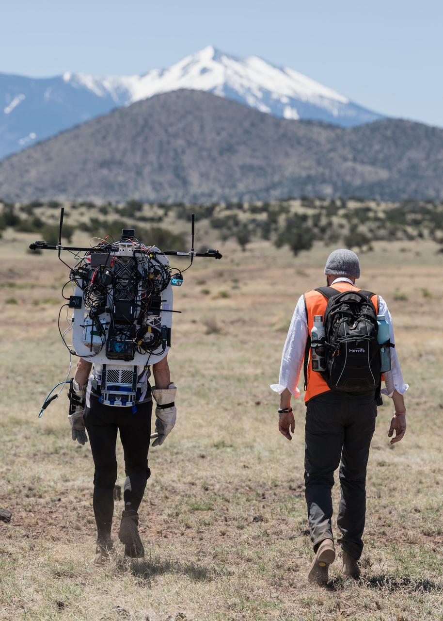
NASA astronaut Kate Rubins walks through the lunar-like landscape wearing the Joint AR (Joint Augmented Reality Visual Informatics System) display during an advanced technology run in the San Francisco Volcanic Field in Northern Arizona on May 19, 2024. The suit display features include navigation, photo capture, graphical format of consumables, procedure viewing, mission control updates, and other augmented reality cues and graphics. The team successfully tested navigation displays using data from four different data streams: GPS (Global Positioning System)/IMU (Inertial Measurement Unit), camera/IMU, LiDAR (Light Detection and Ranging), and static maps. Technology like this may be used for future Artemis missions to augment mission control communication and help guide crew back to the lunar lander. Credit: NASA/Josh Valcarcel
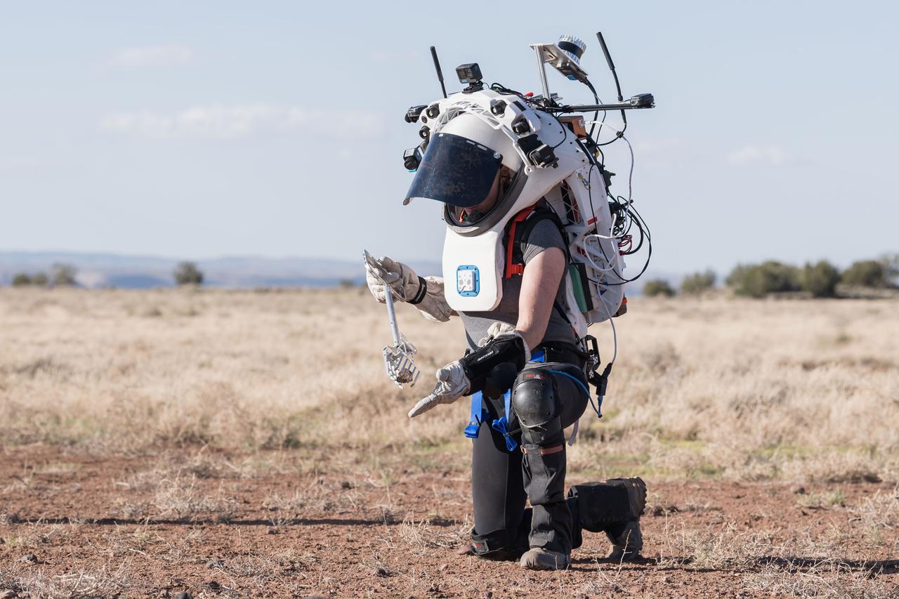
NASA astronaut Kate Rubins uses tongs to pick up a geologic sample while wearing the Joint AR (Joint Augmented Reality Visual Informatics System) display during an advanced technology run in the San Francisco Volcanic Field in Northern Arizona on May 21, 2024. The suit display features include navigation, photo capture, graphical format of consumables, procedure viewing, mission control updates, and other augmented reality cues and graphics. The team successfully tested navigation displays using data from four different data streams: GPS (Global Positioning System)/IMU (Inertial Measurement Unit), camera/IMU, LiDAR (Light Detection and Ranging), and static maps. Technology like this may be used for future Artemis missions to augment mission control communication and help guide crew back to the lunar lander. Credit: NASA/Josh Valcarcel
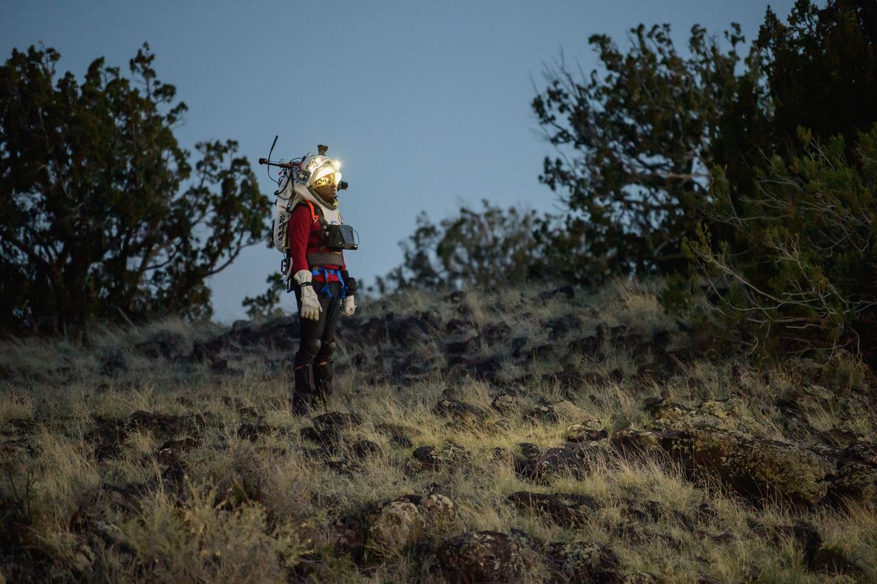
NASA astronaut Andre Douglas views the lunar-like landscape at dusk while wearing the Joint AR (Joint Augmented Reality Visual Informatics System) display during an advanced technology run in the San Francisco Volcanic Field in Northern Arizona on May 21, 2024. The suit display features include navigation, photo capture, graphical format of consumables, procedure viewing, mission control updates, and other augmented reality cues and graphics. The team successfully tested navigation displays using data from four different data streams: GPS (Global Positioning System)/IMU (Inertial Measurement Unit), camera/IMU, LiDAR (Light Detection and Ranging), and static maps. Technology like this may be used for future Artemis missions to augment mission control communication and help guide crew back to the lunar lander. Credit: NASA/Josh Valcarcel

NASA astronaut Andre Douglas wears the Joint AR (Joint Augmented Reality Visual Informatics System) display during a nighttime advanced technology run in the San Francisco Volcanic Field in Northern Arizona on May 21, 2024. The suit display features include navigation, photo capture, graphical format of consumables, procedure viewing, mission control updates, and other augmented reality cues and graphics. The team successfully tested navigation displays using data from four different data streams: GPS (Global Positioning System)/IMU (Inertial Measurement Unit), camera/IMU, LiDAR (Light Detection and Ranging), and static maps. Technology like this may be used for future Artemis missions to augment mission control communication and help guide crew back to the lunar lander. Credit: NASA/Josh Valcarcel
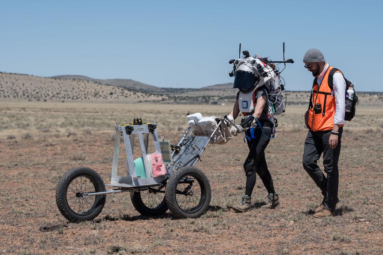
NASA astronaut Kate Rubins pushes a cart through the lunar-like landscape while wearing the Joint AR (Joint Augmented Reality Visual Informatics System) display during an advanced technology run in the San Francisco Volcanic Field in Northern Arizona on May 19, 2024. The suit display features include navigation, photo capture, graphical format of consumables, procedure viewing, mission control updates, and other augmented reality cues and graphics. The team successfully tested navigation displays using data from four different data streams: GPS (Global Positioning System)/IMU (Inertial Measurement Unit), camera/IMU, LiDAR (Light Detection and Ranging), and static maps. Technology like this may be used for future Artemis missions to augment mission control communication and help guide crew back to the lunar lander. Credit: NASA/Josh Valcarcel
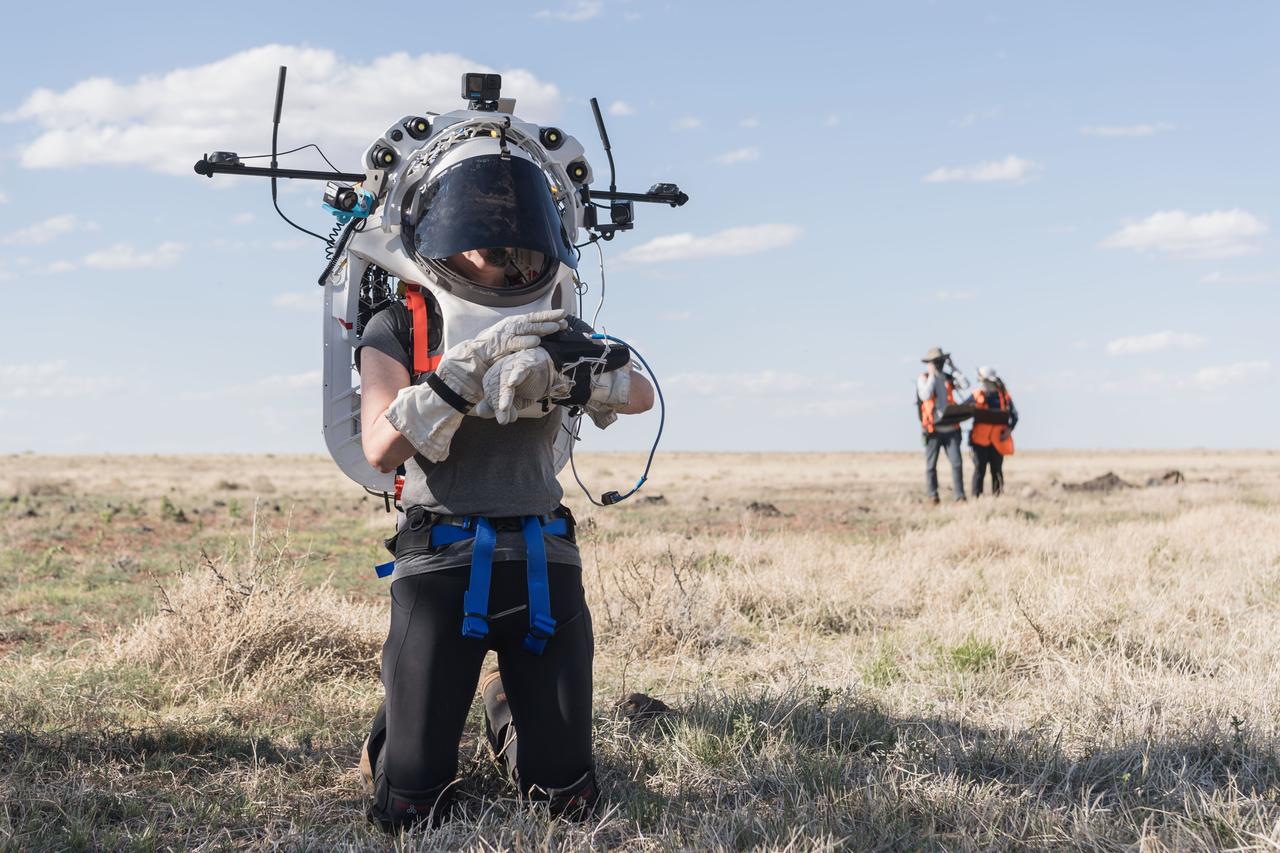
NASA astronaut Kate Rubins uses the hand controller on her wrist to display information while wearing the Joint AR (Joint Augmented Reality Visual Informatics System) display during an advanced technology run in the San Francisco Volcanic Field in Northern Arizona on May 21, 2024. The suit display features include navigation, photo capture, graphical format of consumables, procedure viewing, mission control updates, and other augmented reality cues and graphics. The team successfully tested navigation displays using data from four different data streams: GPS (Global Positioning System)/IMU (Inertial Measurement Unit), camera/IMU, LiDAR (Light Detection and Ranging), and static maps. Technology like this may be used for future Artemis missions to augment mission control communication and help guide crew back to the lunar lander. Credit: NASA/Josh Valcarcel
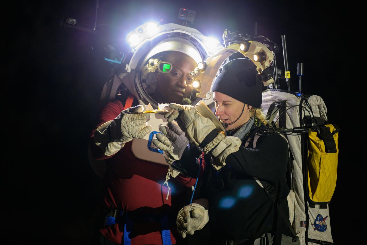
NASA astronauts Andre Douglas and Kate Rubins during a nighttime advanced technology run in the San Francisco Volcanic Field in Northern Arizona on May 21, 2024. Douglas is wearing the Joint AR (Joint Augmented Reality Visual Informatics System) display. The suit display features include navigation, photo capture, graphical format of consumables, procedure viewing, mission control updates, and other augmented reality cues and graphics. The team successfully tested navigation displays using data from four different data streams: GPS (Global Positioning System)/IMU (Inertial Measurement Unit), camera/IMU, LiDAR (Light Detection and Ranging), and static maps. Technology like this may be used for future Artemis missions to augment mission control communication and help guide crew back to the lunar lander. Credit: NASA/Josh Valcarcel
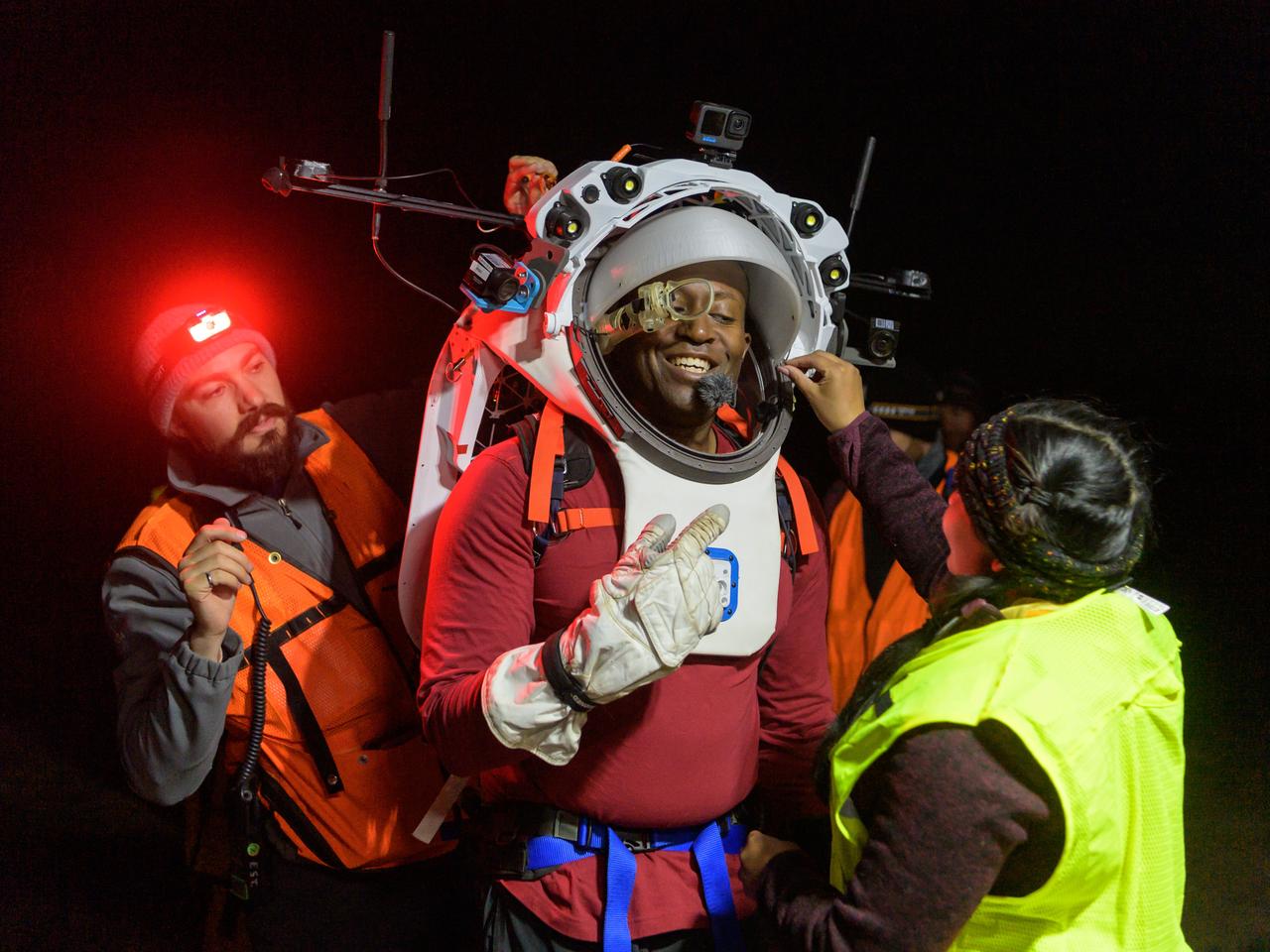
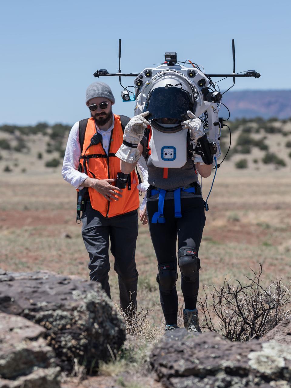
Engineers help NASA astronaut Andre Douglas adjust the Joint AR (Joint Augmented Reality Visual Informatics System) display he’s wearing during a nighttime advanced technology run in the San Francisco Volcanic Field in Northern Arizona on May 21, 2024. The suit display features include navigation, photo capture, graphical format of consumables, procedure viewing, mission control updates, and other augmented reality cues and graphics. The team successfully tested navigation displays using data from four different data streams: GPS (Global Positioning System)/IMU (Inertial Measurement Unit), camera/IMU, LiDAR (Light Detection and Ranging), and static maps. Technology like this may be used for future Artemis missions to augment mission control communication and help guide crew back to the lunar lander. Credit: NASA/Josh Valcarcel
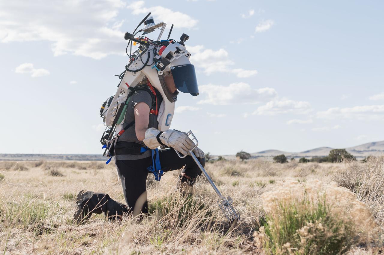
NASA astronaut Kate Rubins uses tongs to collect geologic samples while wearing the Joint AR (Joint Augmented Reality Visual Informatics System) display during an advanced technology run in the San Francisco Volcanic Field in Northern Arizona on May 21, 2024. The suit display features include navigation, photo capture, graphical format of consumables, procedure viewing, mission control updates, and other augmented reality cues and graphics. The team successfully tested navigation displays using data from four different data streams: GPS (Global Positioning System)/IMU (Inertial Measurement Unit), camera/IMU, LiDAR (Light Detection and Ranging), and static maps. Technology like this may be used for future Artemis missions to augment mission control communication and help guide crew back to the lunar lander. Credit: NASA/Josh Valcarcel
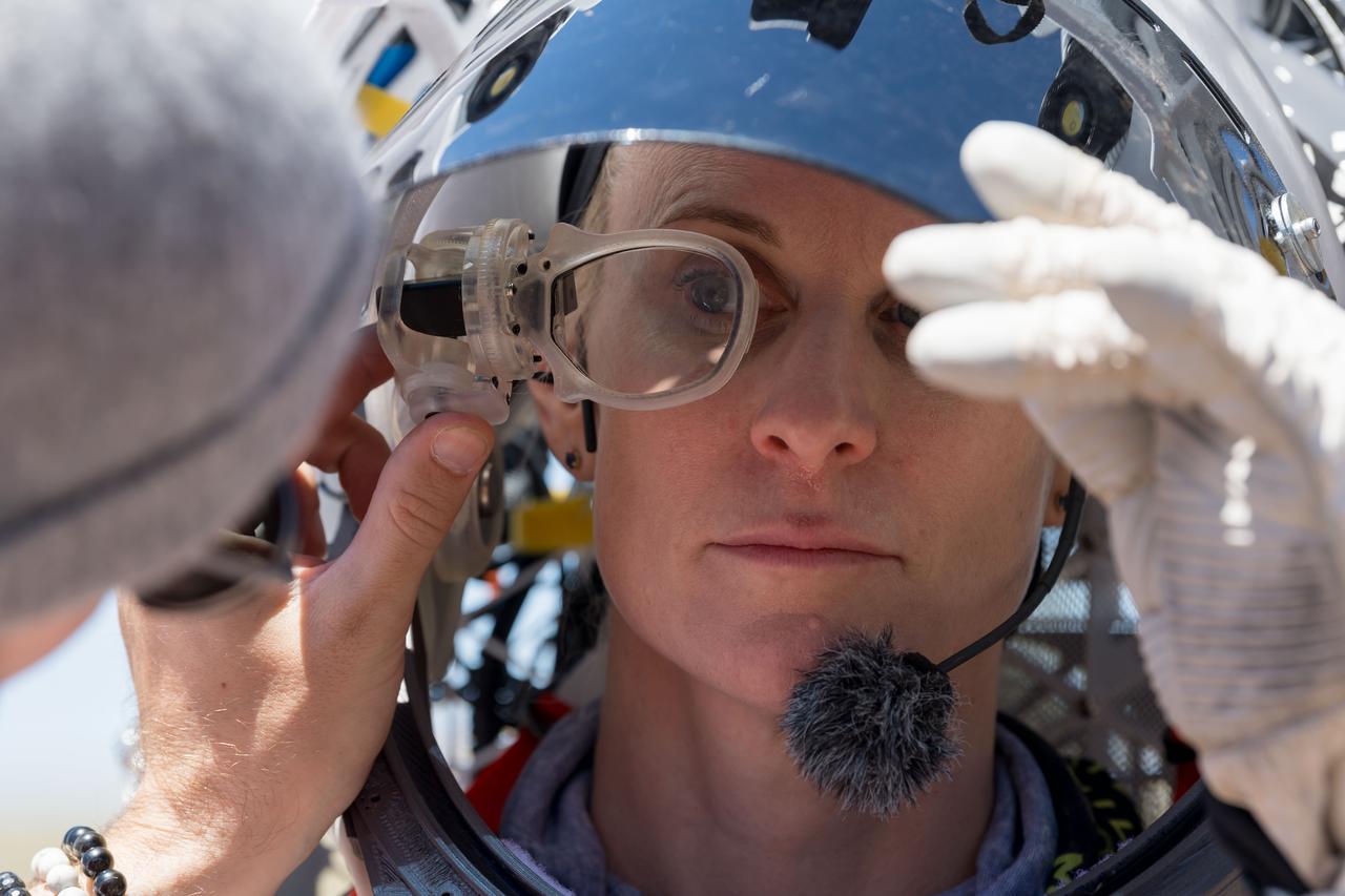
An engineer helps NASA astronaut Kate Rubins adjust the lens on the Joint AR (Joint Augmented Reality Visual Informatics System) display she’s wearing during an advanced technology run in the San Francisco Volcanic Field in Northern Arizona on May 19, 2024. The suit display features include navigation, photo capture, graphical format of consumables, procedure viewing, mission control updates, and other augmented reality cues and graphics. The team successfully tested navigation displays using data from four different data streams: GPS (Global Positioning System)/IMU (Inertial Measurement Unit), camera/IMU, LiDAR (Light Detection and Ranging), and static maps. Technology like this may be used for future Artemis missions to augment mission control communication and help guide crew back to the lunar lander. Credit: NASA/Josh Valcarcel
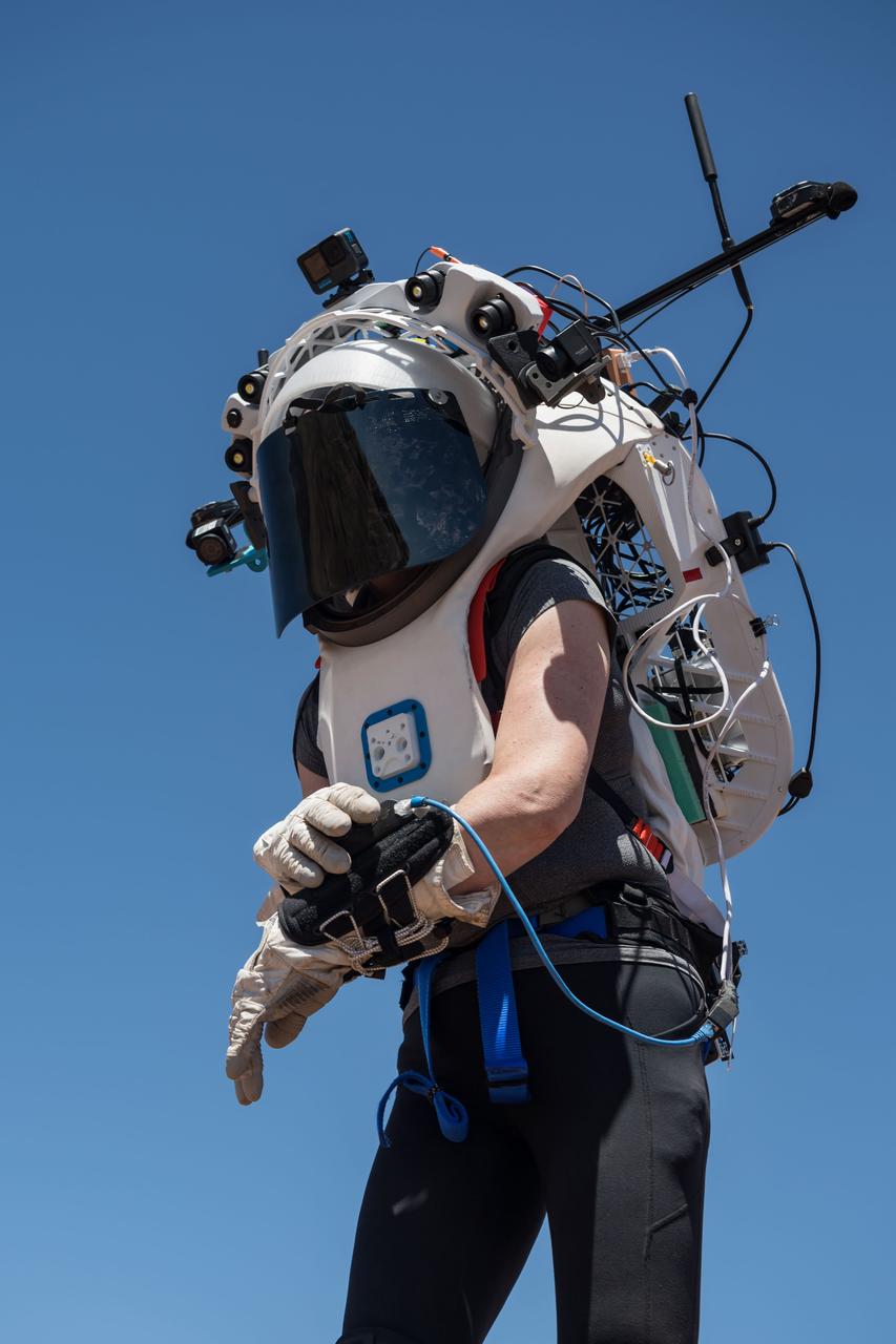
NASA astronaut Kate Rubins uses the hand controller on her wrist to display information while wearing the Joint AR (Joint Augmented Reality Visual Informatics System) display during an advanced technology run in the San Francisco Volcanic Field in Northern Arizona on May 19, 2024. The suit display features include navigation, photo capture, graphical format of consumables, procedure viewing, mission control updates, and other augmented reality cues and graphics. The team successfully tested navigation displays using data from four different data streams: GPS (Global Positioning System)/IMU (Inertial Measurement Unit), camera/IMU, LiDAR (Light Detection and Ranging), and static maps. Technology like this may be used for future Artemis missions to augment mission control communication and help guide crew back to the lunar lander. Credit: NASA/Josh Valcarcel
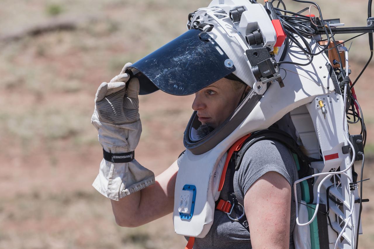
NASA astronaut Kate Rubins opens the sun visor on the Joint AR (Joint Augmented Reality Visual Informatics System) display she’s wearing during an advanced technology run in the San Francisco Volcanic Field in Northern Arizona on May 19, 2024. The suit display features include navigation, photo capture, graphical format of consumables, procedure viewing, mission control updates, and other augmented reality cues and graphics. The team successfully tested navigation displays using data from four different data streams: GPS (Global Positioning System)/IMU (Inertial Measurement Unit), camera/IMU, LiDAR (Light Detection and Ranging), and static maps. Technology like this may be used for future Artemis missions to augment mission control communication and help guide crew back to the lunar lander. Credit: NASA/Josh Valcarcel
NASA astronaut Kate Rubins walks through the lunar-like landscape wearing the Joint AR (Joint Augmented Reality Visual Informatics System) display during an advanced technology run in the San Francisco Volcanic Field in Northern Arizona on May 19, 2024. The suit display features include navigation, photo capture, graphical format of consumables, procedure viewing, mission control updates, and other augmented reality cues and graphics. The team successfully tested navigation displays using data from four different data streams: GPS (Global Positioning System)/IMU (Inertial Measurement Unit), camera/IMU, LiDAR (Light Detection and Ranging), and static maps. Technology like this may be used for future Artemis missions to augment mission control communication and help guide crew back to the lunar lander. Credit: NASA/Josh Valcarcel
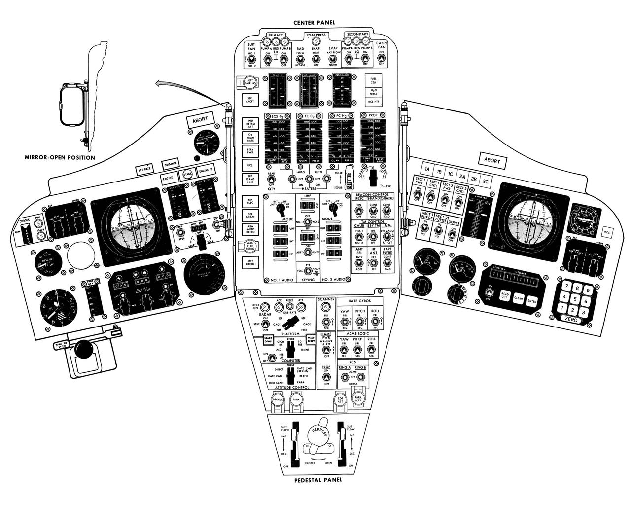
S65-14095 (1965) --- Artist concept of the Gemini spacecraft control panel.

S73-02395 (August 1973) --- An artist?s concept illustrating an Apollo-type spacecraft (on left) about to dock with a Soviet Soyuz-type spacecraft. A recent agreement between the United States and the Union of Soviet Socialist Republics provides for the docking in space of the Soyuz and Apollo-type spacecraft in Earth orbit in 1975. The joint venture is called the Apollo-Soyuz Test Project.
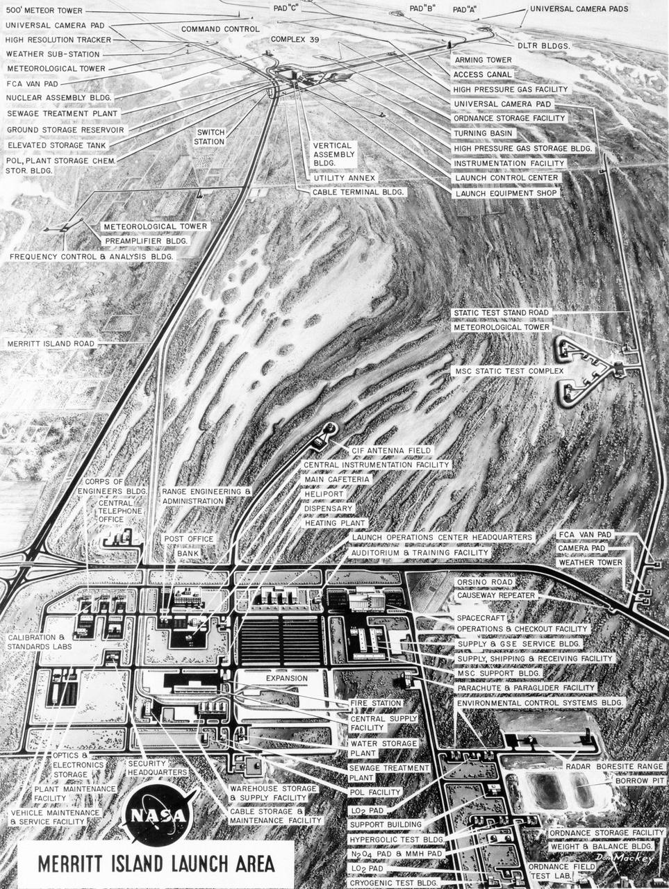
S63-23618 (December 1963) --- Aerial oblique artist concept of the Merritt Island Launch Complex, Merritt Island, Florida. Photo credit: NASA
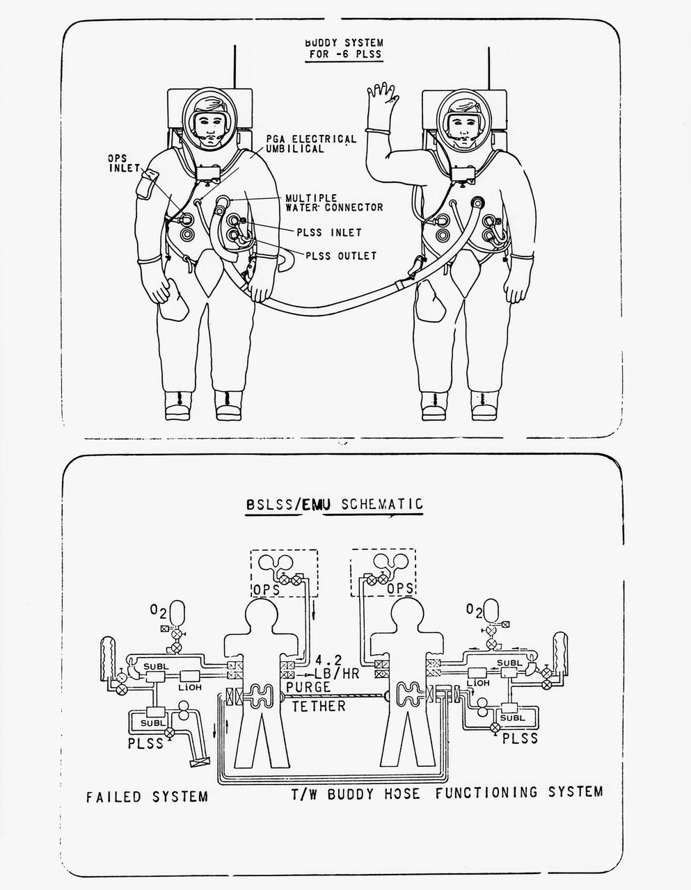
S70-56965 (December 1970) --- Drawing of the newly developed Buddy Secondary Life Support System (BSLSS). The life-sustaining system will be provided for the first time on the Apollo 14 lunar landing mission. The two flexible hoses, to be used on the second Apollo 14 extravehicular activity (EVA), will be among the paraphernalia on the Modular Equipment Transporter (MET) or two-wheeled workshop, and readily accessible in an emergency. During EVAs the Portable Life Support System (PLSS) supplies the astronaut with breathing and suit-pressurizing oxygen and water flow for the liquid-cooling garment -- a suit of knitted long underwear with thin tubing woven in the torso and limbs. The tubes carry water from a reservoir in the PLSS, and the circulating water serves to carry the astronaut's metabolic heat to a heat exchanger in the PLSS. Before the BSLSS was devised, the emergency tank was required to furnish not only suit pressure and breathing oxygen, but also cooling through a high oxygen flow rate. The BSLSS, by sharing the water supply between the two crewmen, stretches the time of the emergency oxygen from about 40 minutes to 60 to 75 minutes.
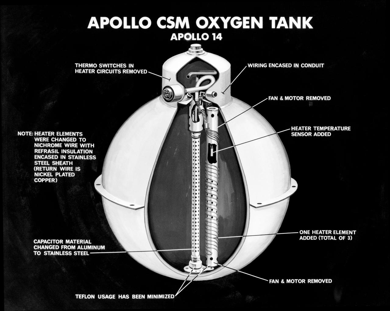
S71-16745 (January 1971) --- An artist's concept illustrating a cutaway view of one of the three oxygen tanks of the Apollo 14 spacecraft. This is the new Apollo oxygen tank design, developed since the Apollo 13 oxygen tank explosion. Apollo 14 has three oxygen tanks redesigned to eliminate ignition sources, minimize the use of combustible materials, and simplify the fabrication process. The third tank has been added to the Apollo 14 Service Module, located in the SM's sector one, apart from the pair of oxygen tanks in sector four. Arrows point out various features of the oxygen tank.
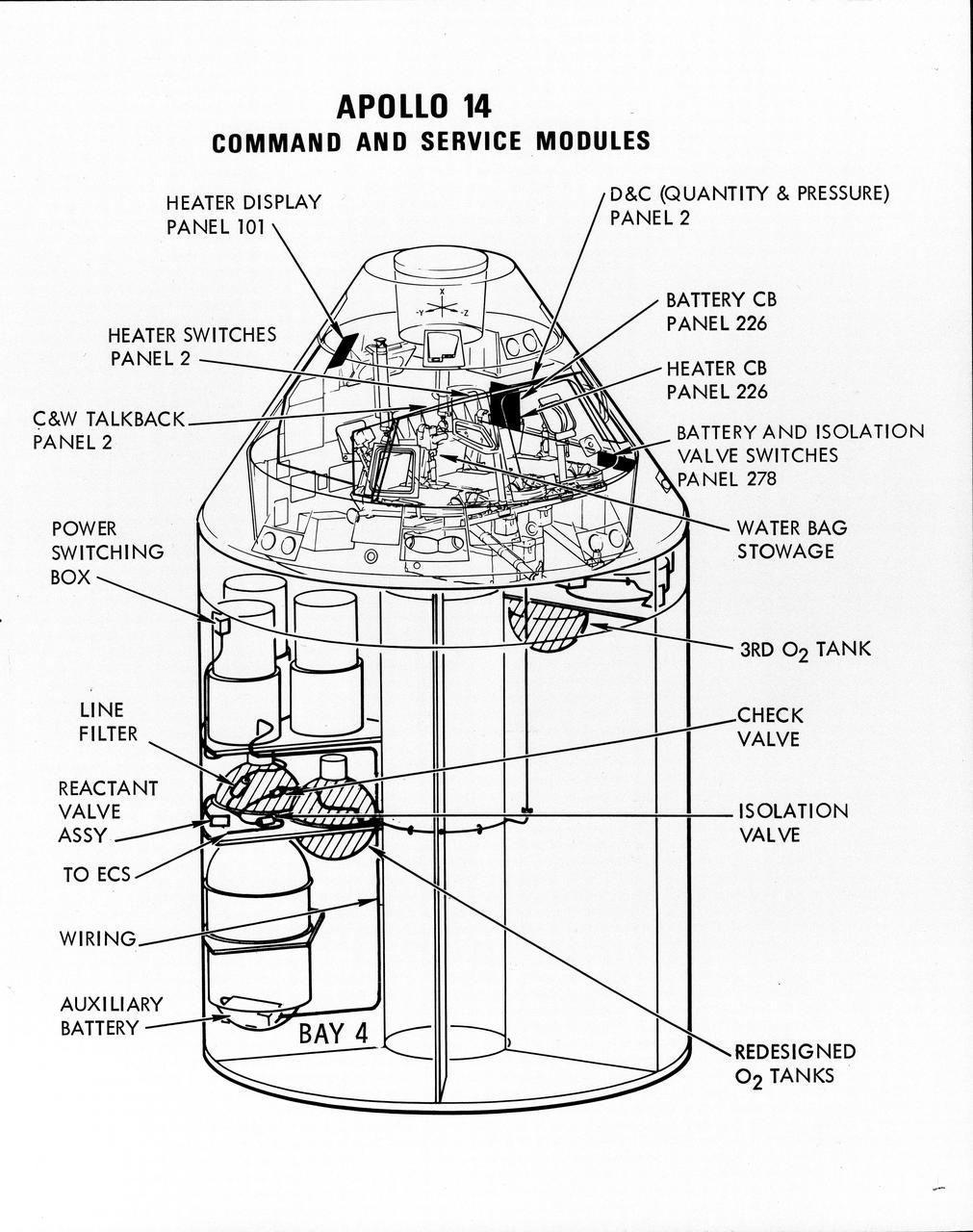
S71-16823 (January 1971) --- A line drawing illustrating a cutaway view of the Apollo 14 Command and Service Modules, showing the engineering changes in the CSM which were recommended by the Apollo 13 Review Board. (The Apollo 13 abort was caused by a short circuit and wiring overheating in one of the SM cryogenic oxygen tanks.) The major changes to the Apollo 14 CSM include adding a third cryogenic oxygen tank installed in a heretofore empty bay (in sector one) of the SM, addition of an auxiliary battery in the SM as a backup in case of fuel cell failure, and removal of destratification fans in the cryogenic oxygen tanks and removal of thermostat switches from the oxygen tank heater circuits. Provision for stowage of an emergency five-gallon supply of drinking water has been added to the CM.
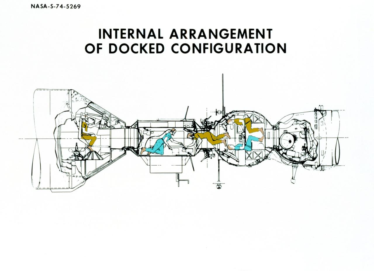
S74-05269 (December 1974) --- An artist?s drawing illustrating the internal arrangement of the Apollo and Soyuz spacecraft in Earth orbit in a docked configuration. The three American Apollo crewmen and the two Soviet Soyuz crewmen will transfer to each other?s spacecraft during the July 1975 ASTP mission. The four Apollo-Soyuz Test Project visible components are, left to right, the Apollo Command Module, the Docking Module, the Soyuz Orbital Module and the Soyuz Descent Vehicle.
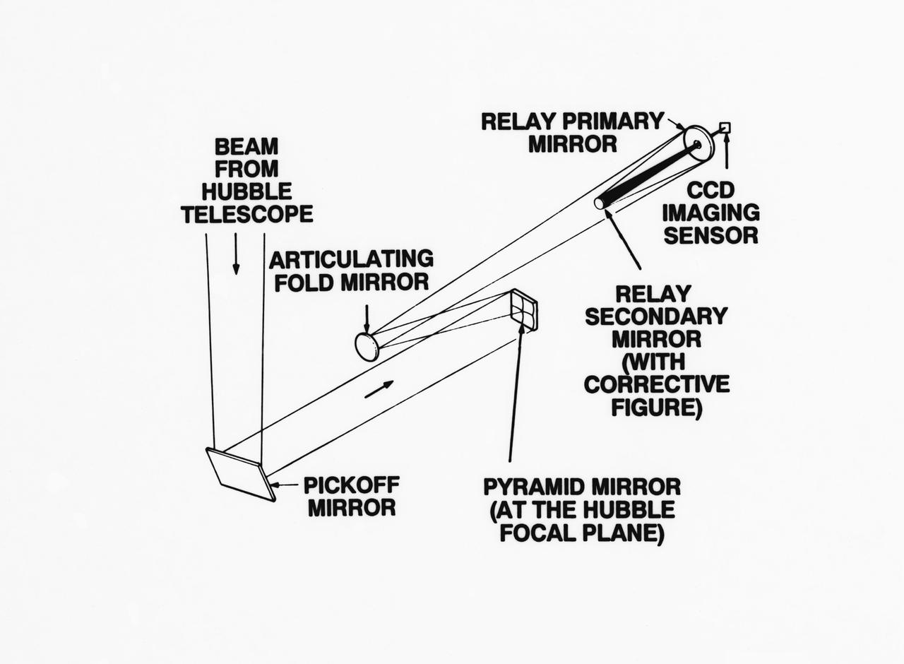
S93-33258 (15 Mar 1993) --- An optical schematic diagram of one of the four channels of the Wide Field\Planetary Camera-2 (WF\PC-2) shows the path taken by beams from the Hubble Space Telescope (HST) before an image is formed at the camera's charge-coupled devices. A team of NASA astronauts will pay a visit to the HST later this year, carrying with them the new WF/PC-2 to replace the one currently on the HST. The Jet Propulsion Laboratory in Pasadena, California has been working on the replacement system for several months. See NASA photo S93-33257 for a close-up view of tiny articulating mirrors designed to realign incoming light in order to make certain the beams fall precisely in the middle of the secondary mirrors.
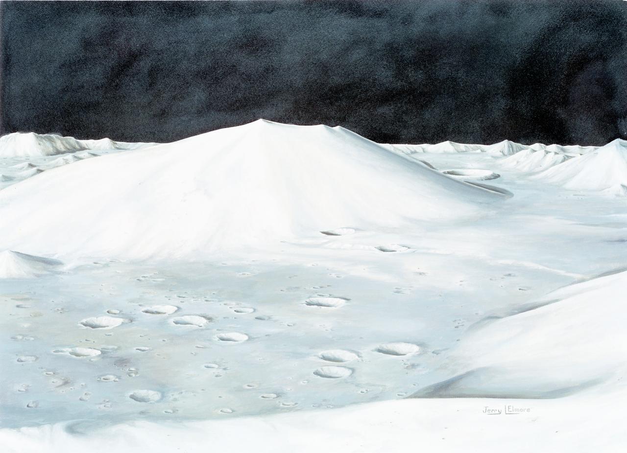
S72-49761 (October 1972) --- An artist's concept illustrating the topographical layout of the Taurus-Littrow landing site of the Apollo 17 lunar landing mission. The Lunar Module touchdown point is in the center of the smooth area in the middle of the picture. The imposing mountain in the center is South Massif. A portion of North Massif is in the lower right corner of the photograph. Note the ridge-like feature extending from South Massif to North Massif. The southern portion of the ridge is called Lee Scarp and the northerly portion Lincoln Scarp. (This concept is by JSC artist Jerry Elmore).
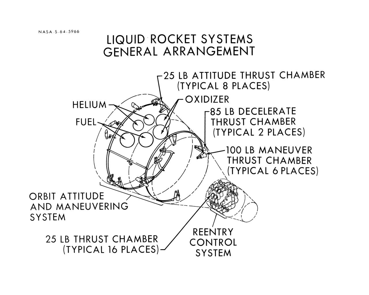
S64-05966 (1964) --- Diagram shows the general arrangement of the liquid rocket systems on the Gemini spacecraft are shown. The locations of the 25-pound, 85-pound and 100-pound thrusters of the orbital attitude and maneuver system and the 25-pound thrusters of the re-entry control system are shown.
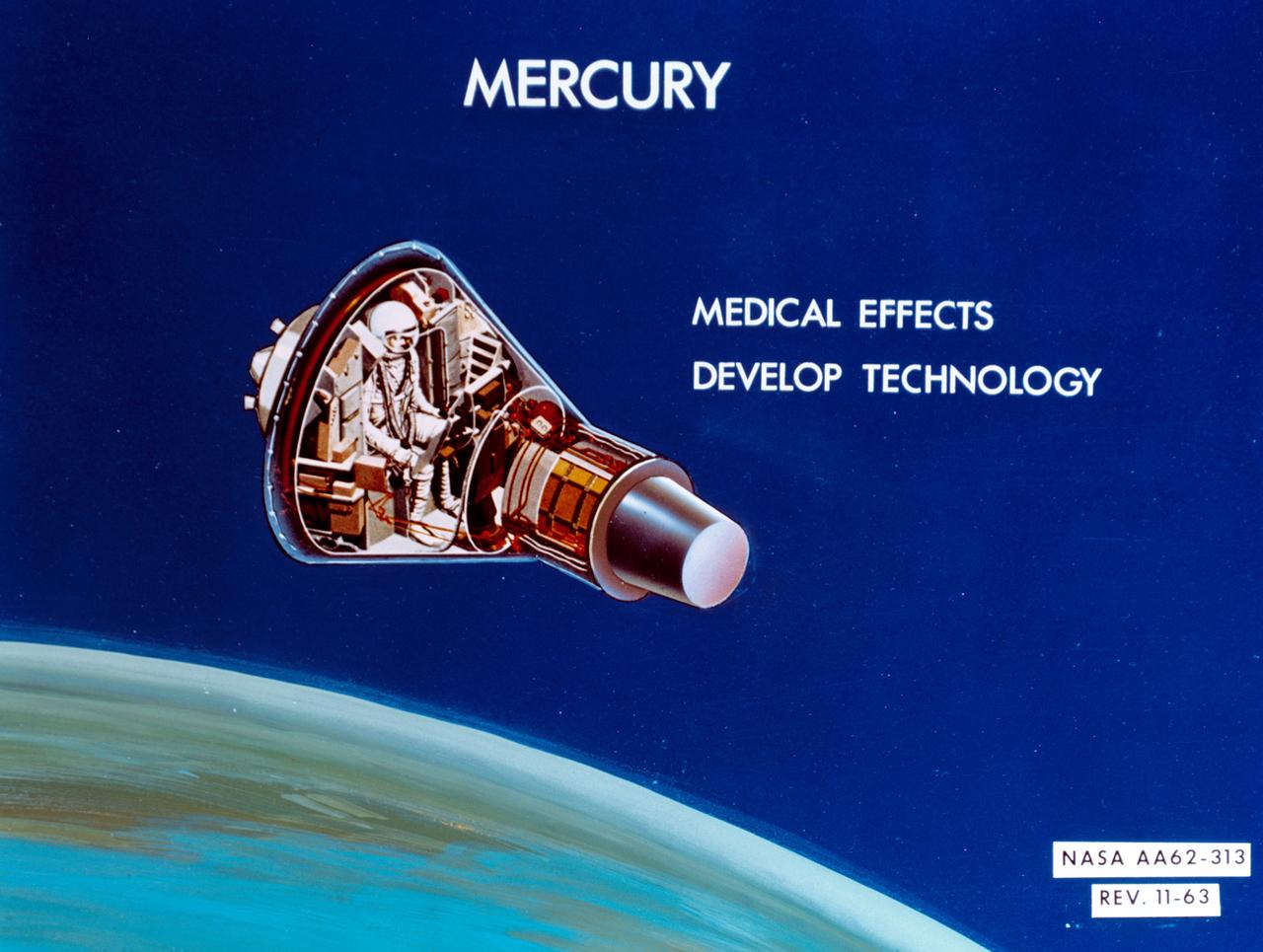
S64-14286 (11 Feb. 1964) --- An artist's concept of Mercury: Medical effects; develop technology. Photo credit: NASA
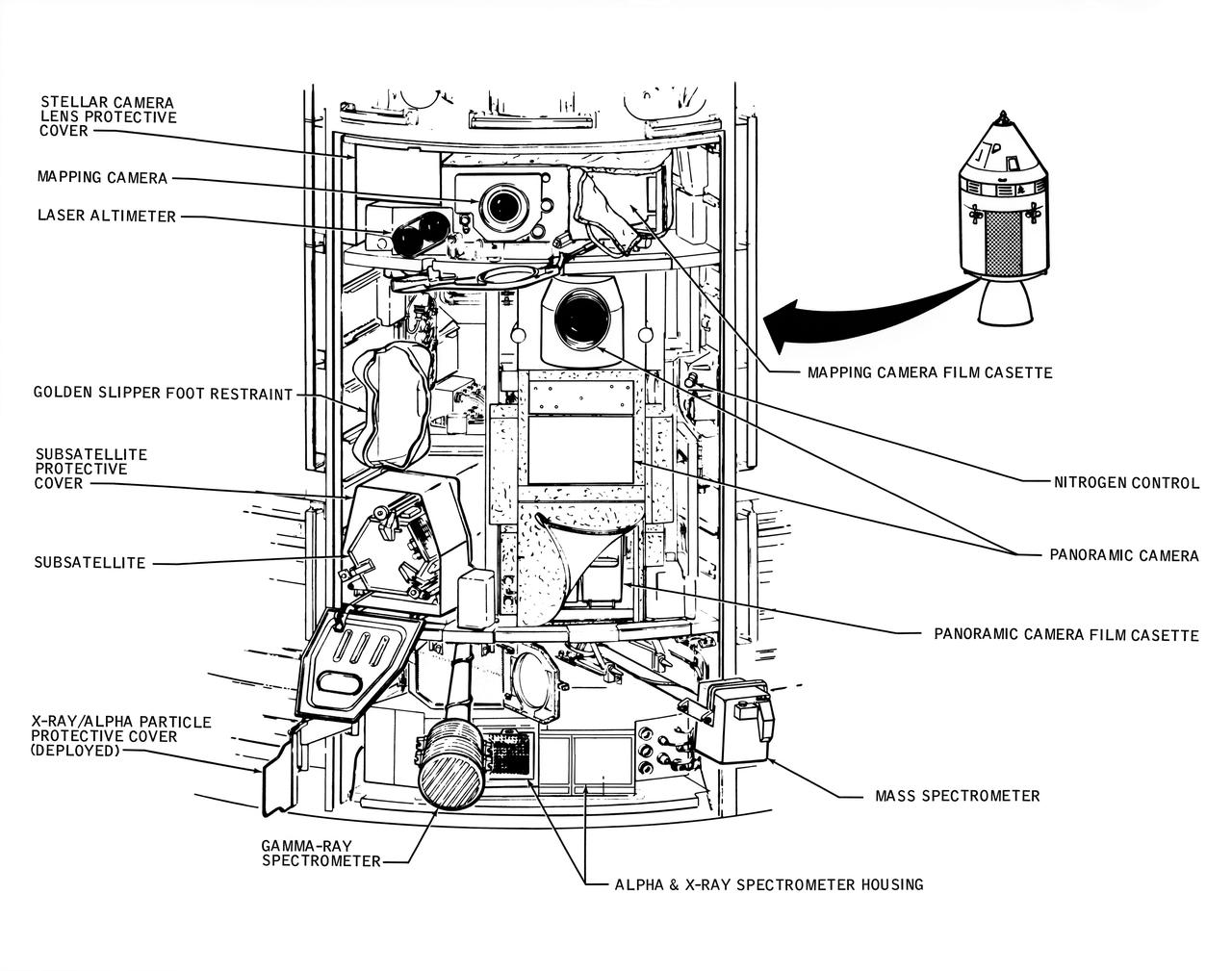
A line drawing illustrating the layout of the Scietific Instrument Module (SIM) of the Apollo 16 Service Module. Shown here is the location in the SIM bay of the equipment for each orbital experiment. Arrows point to various components of the SIM bay. The sensors for the gamma ray spectrometer and the mas spectrometer both extend outward on a boom about 25 feet when the instruments are in use. The subsatellite is launched while the Service Module is in orbit around the moon. The film cassettes must be retrieved prior to Command Module/Service Module separation.
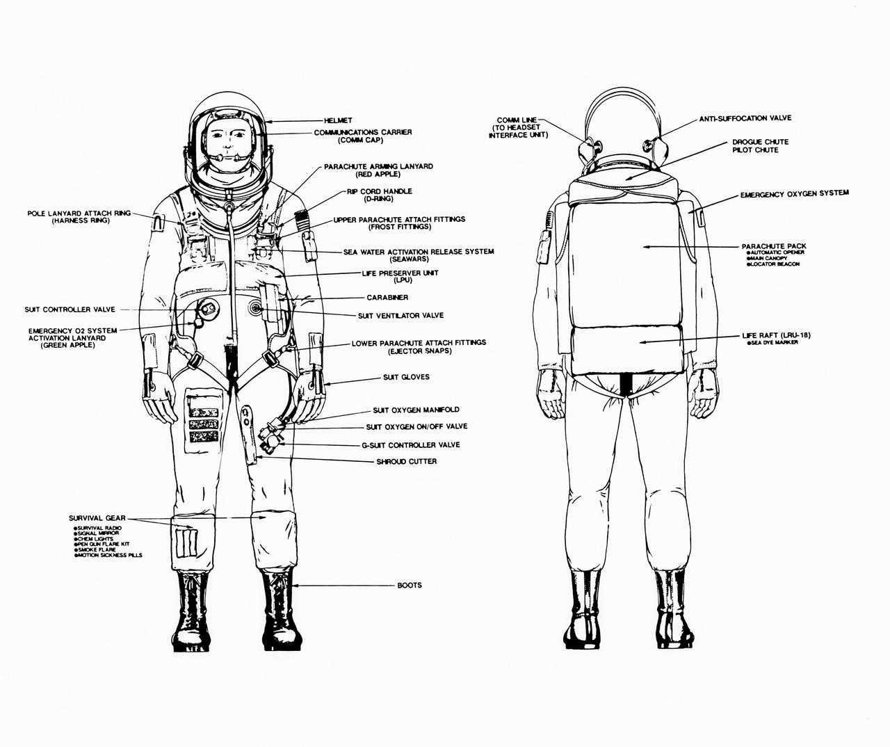
Line drawings illustrate the front and back of the space shuttle launch and entry suit (LES) and labels identify various components. LES was designed for STS-26, the return to flight mission, and subsequent missions. Included in the crew escape system (CES) package are launch and entry helmet (LEH) with communications carrier (COMM CAP), parachute pack and harness, life preserver unit (LPU), life raft unit (LRU), LES gloves, suit oxygen manifold and valves, boots, and survival gear. Details of larger components are also identified.
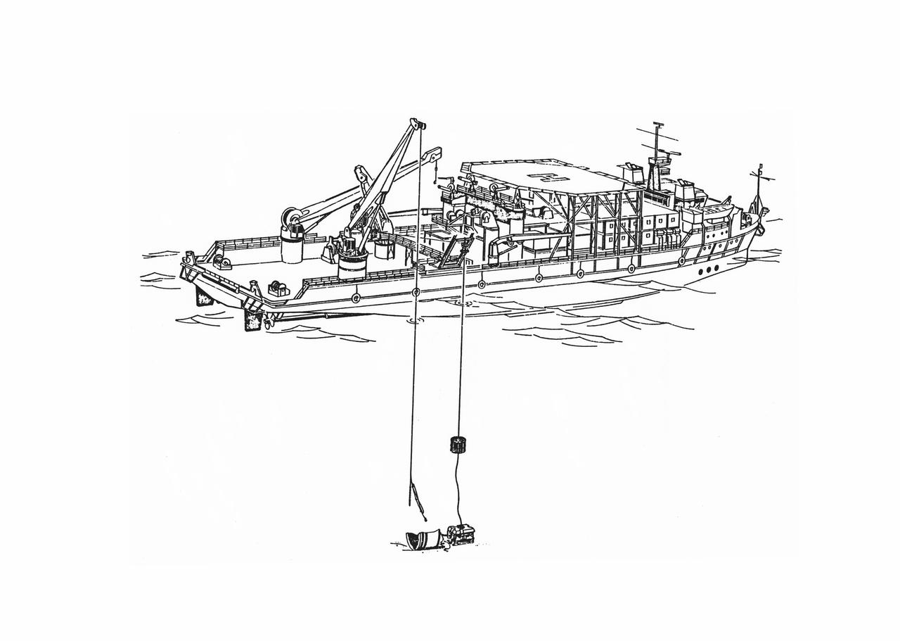
S86-30088 (March 1986) --- Salvage operations offshore of Kennedy Space Center, are depicted in this artist’s concept showing a grapple and recovery fixture (left) being directed through the use of a remote video system suspended from the recovery ship. Photo credit: NASA
S93-48826 (November 1993) --- This artist's rendition of the 1993 Hubble Space Telescope (HST) servicing mission shows astronauts installing the new Wide Field/Planetary Camera (WF/PC 2). The instruments to replace the original camera and contains corrective optics that compensate for the telescope's flawed primary mirror. During the 11-plus day mission, astronauts are also scheduled to install the Corrective Optics Space Telescope Axial Replacement (COSTAR) -- an optics package that focuses and routes light to the other three instruments aboard the observatory -- a new set of solar array panels, and other hardware and components. The artwork was done for JPL by Paul Hudson.
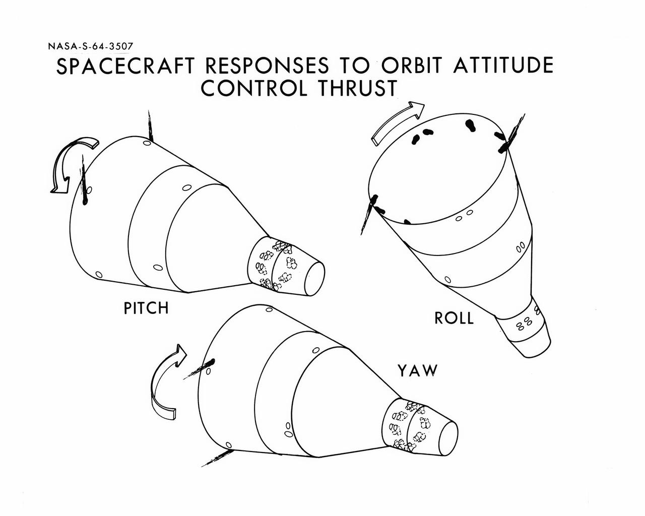
S64-03507 (1964) --- Diagrams shows Gemini spacecraft responses to orbital attitude systems's thrusters. Firing of appropriate combination of the thrusters cause pitch, roll and yaw.
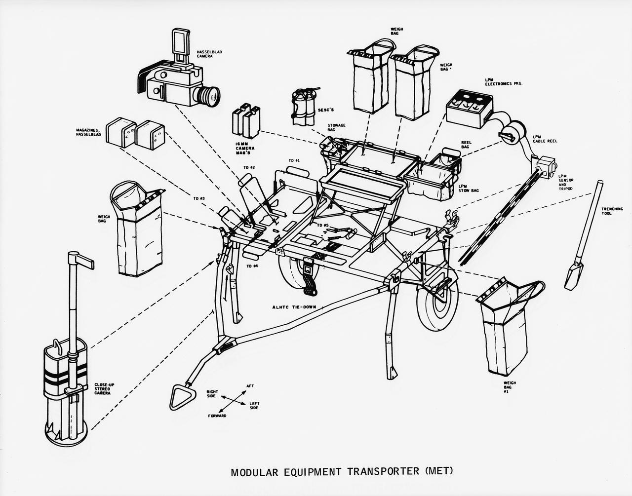
S70-50762 (November 1970) --- A line drawing illustrating layout view of the modular equipment transporter (MET) and its equipment. A MET (or Rickshaw, as it has been nicknamed) will be used on the lunar surface for the first time during the Apollo 14 lunar landing mission. The Rickshaw will serve as a portable workbench with a place for the Apollo lunar hand tools (ALHT) and their carrier, three cameras, two sample container bags, a special environment sample container (SESC), a lunar portable magnetometer (LPM) and spare film magazines.
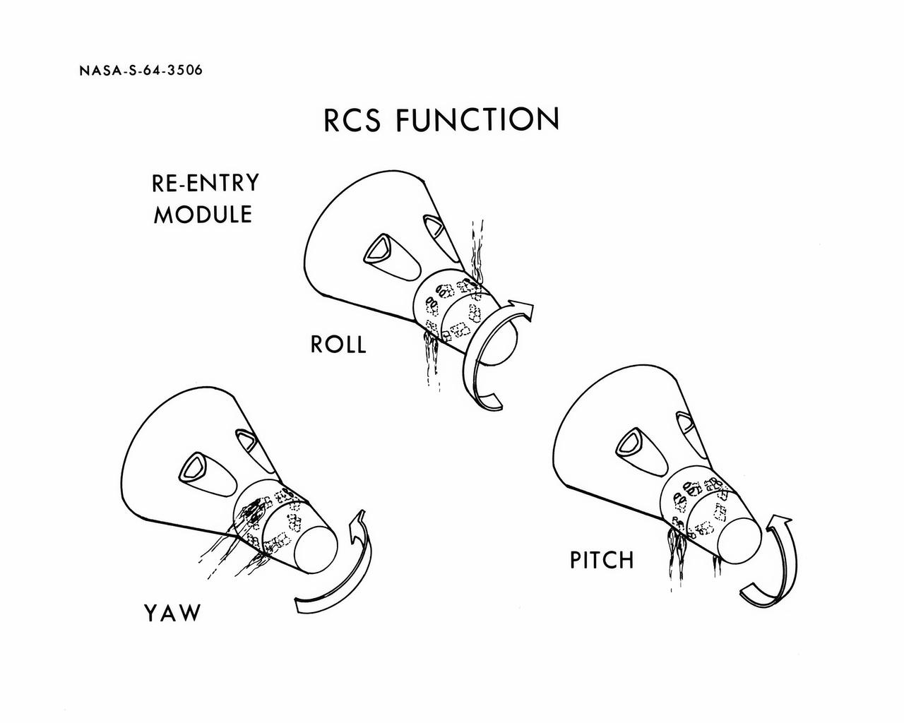
S64-03506 (1964) --- Diagrams shows Gemini spacecraft functions of the thrusters in the Gemini spacecraft's re-entry control system. Thrusters may be fired in various combinations to cause yaw, roll and pitch.
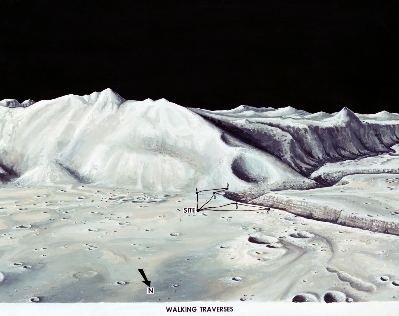
S71-33432 (1 July 1971) --- These alternative traverses can be carried out on foot. They will be used if the Lunar Roving Vehicle (LRV) becomes inoperative. This artist's concept showing part of the Hadley Rille and several of the Apennine Mountains was excerpted from "On the Moon with Apollo 15: A Guidebook to the Hadley-Apennine Region," by Gene Simmons. Artwork by Jerry Elmore.
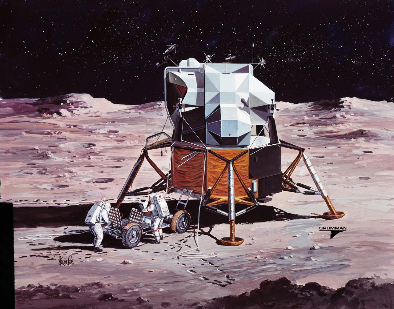
S71-38189 (26 June 1971) --- An artist's concept showing the final steps of readying the Apollo 15 Lunar Roving Vehicle (LRV) or Rover 1 for mobility on the lunar surface. Performing the last few LRV deployment tasks here are, left to right, astronauts James B. Irwin, lunar module pilot, and David R. Scott, commander. More specifically the tasks depicted here include the setting up of the seats and the total releasing of the LRV from the LM. (This is the fourth in a series of four Grumman Aerospace Corporation artist's concepts telling the lunar surface LRV deployment story for Apollo 15).
S71-38188 (26 June 1971) --- An artist's concept showing the Apollo 15 mission commander and the lunar module pilot performing deployment of the Lunar Roving Vehicle (LRV) on the lunar surface. The figure on the left represents astronaut James B. Irwin, lunar module pilot, who here is maintaining a constant pull on the deployment cable to help the LRV unfold, while astronaut David R. Scott (right), commander, pulls the tapes that lower the LRV to the surface. (This is the third in a series of Grumman Aerospace Corporation artist's concepts telling the lunar surface LRV deployment story of the Apollo 15 mission).
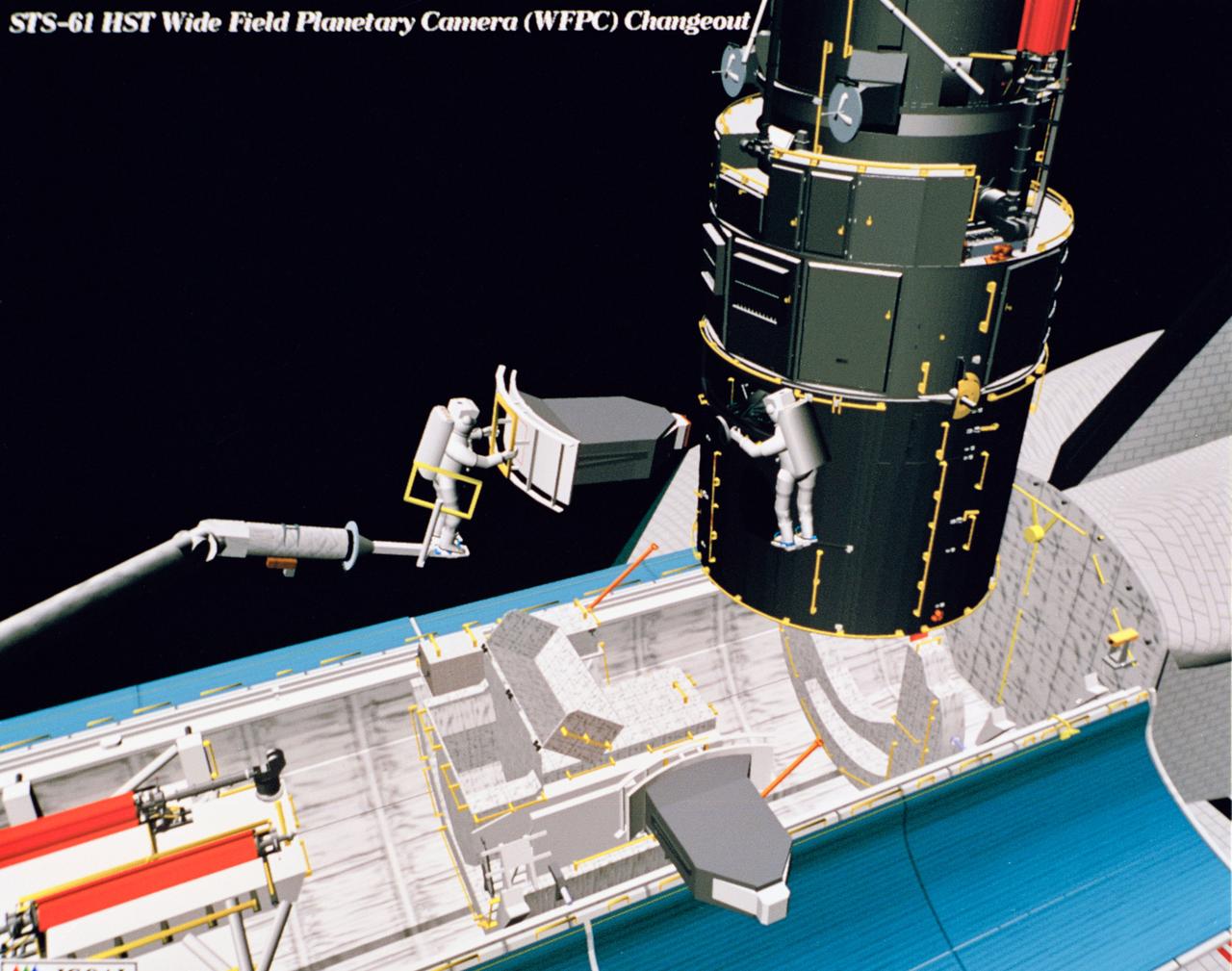
Computer generated scenes depicting the Hubble Space Telescope capture and a sequence of planned events on the planned extravehicular activity (EVA). Scenes include the Remote Manipulator System (RMS) arm assisting two astronauts changing out the Wide Field/Planetary Camera (WF/PC) (48699); RMS arm assisting in the temporary mating of the orbiting telescope to the flight support system in Endeavour's cargo bay (48700); Endeavour's RMS arm assisting in the "capture" of the orbiting telescope (48701); Two astronauts changing out the telescope's coprocessor (48702); RMS arm assistign two astronauts replacing one of the telescope's electronic control units (48703); RMS assisting two astronauts replacing the fuse plugs on the telescope's Power Distribution Unit (PDU) (48704); The telescope's High Resolution Spectrograph (HRS) kit is depicted in this scene (48705); Two astronauts during the removal of the high speed photometer and the installation of the COSTAR instrument (48706); Two astronauts, standing on the RMS, during installation of one of the Magnetic Sensing System (MSS) (48707); High angle view of the orbiting Space Shuttle Endeavour with its cargo bay doors open, revealing the bay's pre-capture configuration. Seen are, from the left, the Solar Array Carrier, the ORU Carrier and the flight support system (48708); Two astronauts performing the replacement of HST's Rate Sensor Units (RSU) (48709); The RMS arm assisting two astronauts with the replacement of the telescope's solar array panels (48710); Two astronauts replacing the telescope's Solar Array Drive Electronics (SADE) (48711).
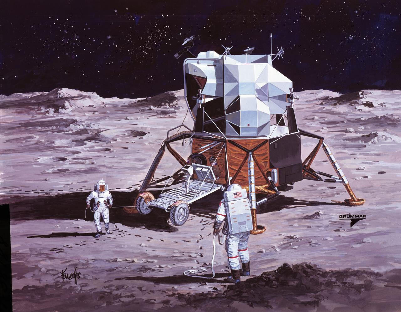
S71-16101 (January 1971) --- A Grumman Aerospace Corporation artist's concept of Apollo 14 crewmen, astronauts Alan B. Shepard Jr., commander, and Edgar D. Mitchell, lunar module pilot, as they set out on their first traverse. Shepard is pulling the Modularized Equipment Transporter (MET) which contains cameras, lunar sample bags, tools and other paraphernalia. Shepard has the Laser Ranging Retro-Reflector (LR-3) in his other hand. Mitchell is carrying the Apollo Lunar Surface Experiments Package (ALSEP) barbell mode.
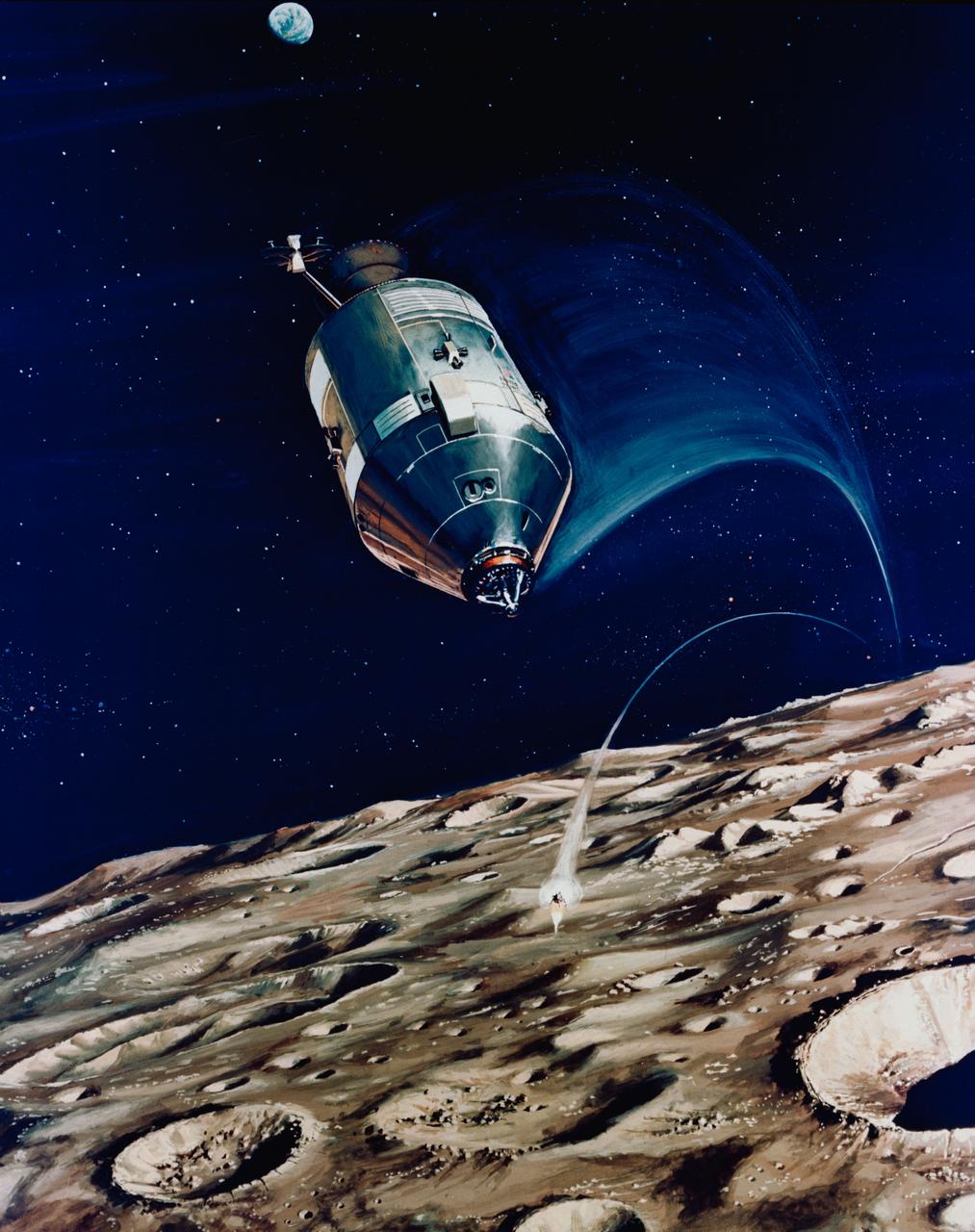
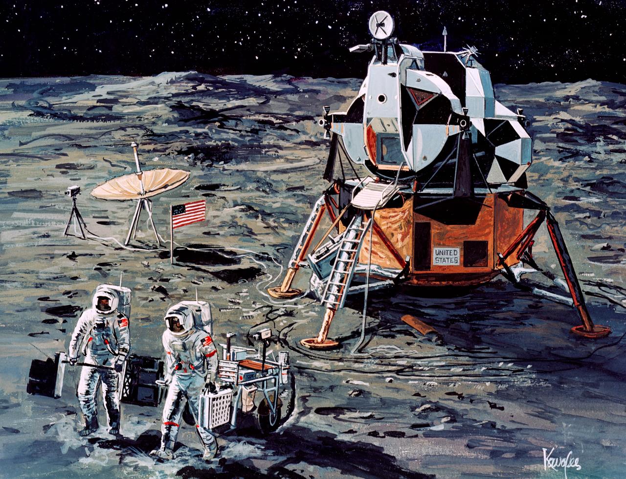
S71-16574 (11 Jan. 1971) --- An artist's concept depicting the Apollo 14 Command and Service Modules (CSM) circling the moon as the Lunar Module (LM) heads toward a lunar landing. While astronaut Stuart A. Roosa, command module pilot, remains with the CSM in lunar orbit, astronauts Alan B. Shepard Jr., commander; and Edgar D. Mitchell, lunar module pilot, will descend in the LM to explore an area in the rugged Fra Mauro highlands.
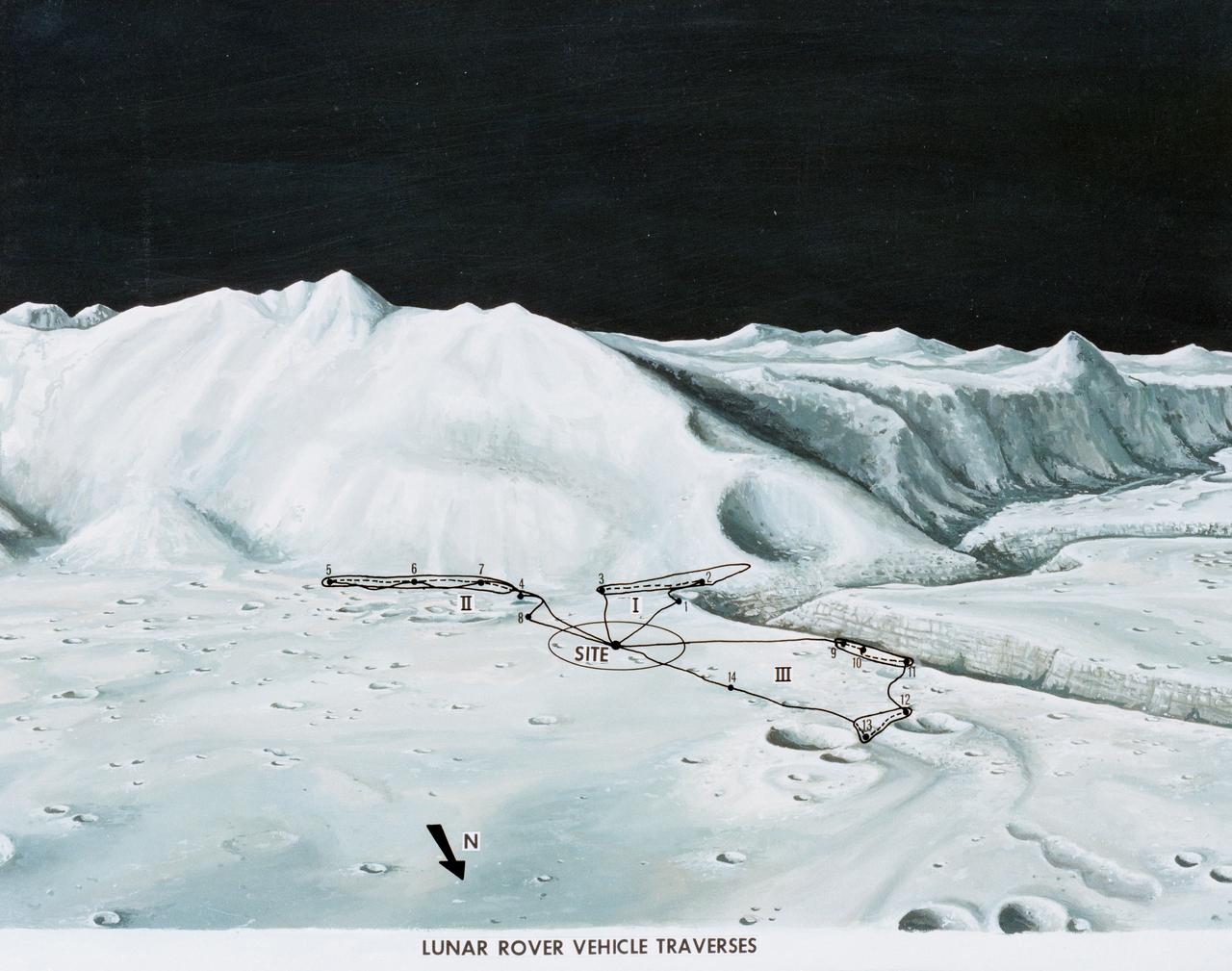
S71-33433 (1 July 1971) --- An artist's concept of the Hadley-Apennine landing site, depicting the traverses planned on the Apollo 15 lunar landing mission using the Lunar Roving Vehicle (LRV). The Roman numerals indicate the three periods of extravehicular activity (EVA). The Arabic numbers represent the station stops. This artist's concept was excerpted from "On the Moon with Apollo 15: A Guidebook to Hadley Rille and the Apennine Mountains," by Gene Simmons. The station stops indicated here are keyed to information given in the publication. Artwork by Jerry Elmore.
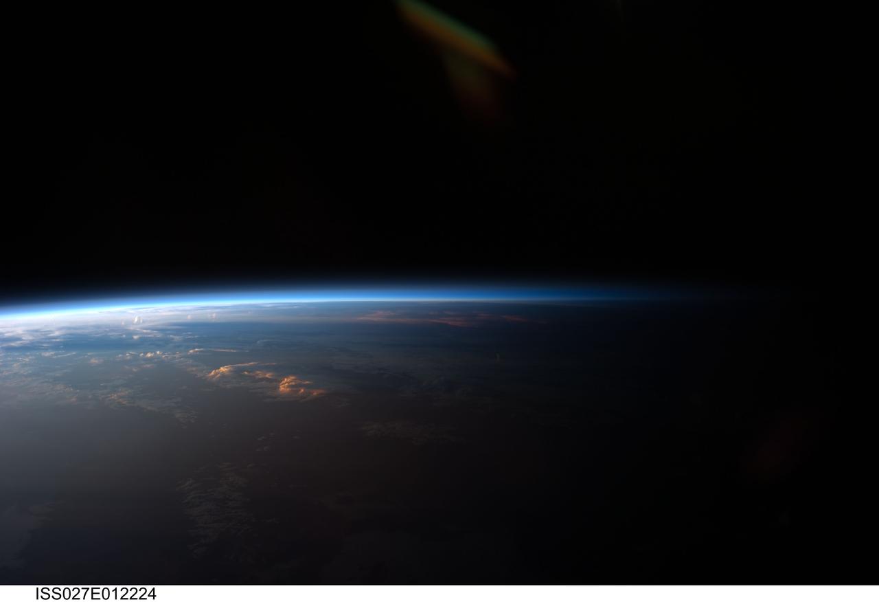
ISS027-E-012224 (12 April 2011) --- Sunset over western South America is featured in this image photographed by an Expedition 27 crew member on the International Space Station. Crew members onboard the space station see, on average, sixteen sunrises and sunsets during a 24-hour orbital period. Each changeover between day and night on the ground is marked by the terminator, or line separating the sunlit side of Earth from the side in darkness. While the terminator is conceptualized as a hard boundary?and is frequently presented as such in graphics and visualizations?in reality the boundary between light and dark is diffuse due to scattering of light by Earth?s atmosphere. This zone of diffuse lighting is experienced as dusk or twilight on the ground ? while the sun is no longer visible, some illumination is still present due to light scattering over the local horizon. The terminator is visible in this photograph trending across the image from lower left to upper right. This panoramic view across central South America, looking towards the northeast, was acquired at approximately 7:37 p.m. local time. Layers of Earth?s atmosphere, colored bright white to deep blue, are visible extending across the horizon (or limb). The highest cloud tops have a reddish glow from the direct light of the setting sun while lower clouds are in twilight. The Salar de Coipasa, a large salt lake in Bolivia, is dimly visible on the night side of the terminator. The salar provides a geographic reference point that allows the location and viewing orientation of the image to be determined.
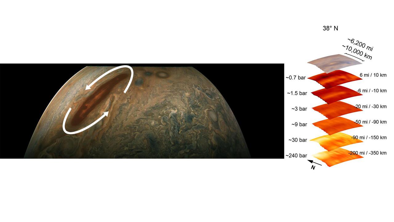
The color-enhanced image on the left is from the JunoCam imager aboard NASA's Juno spacecraft and has been annotated to depict the anticyclonic (counterclockwise) rotation of one of Jupiter's intriguing atmospheric phenomena – a long, brown oval cyclonic region known as a "brown barge." The graphic on the right highlights the large-scale structure of the brown barge as seen by the spacecraft's microwave radiometer (MWR) instrument. Data for the image and the microwave radiometer results were collected during a low flyby of Jupiter. Brown barges usually lie within Jupiter's dark North Equatorial Belt, although they are sometimes found in the similarly dark South Equatorial Belt as well. They can often be difficult to detect visually because their color blends in with the dark surroundings. Brown barges usually dissipate after the entire cloud belt undergoes an upheaval and reorganizes itself. Juno is providing the first glimpses of the detailed structure within such a barge. The radiometer data was acquired from the six channels of MWR. Each MWR channel peers progressively deeper below the visible cloud tops. In fact, the MWR instrument enables Juno to see deeper into Jupiter than any previous spacecraft or Earth-based observations. Unlike Earth, which as a solid surface, Jupiter is a gas giant with no discernable solid surface. So the planetary science community has defined the "base" of Jupiter's atmosphere as the location where its pressure is equivalent to 1 bar. The bar is a metric unit of pressure that, at 14.5 pounds per square inch, is slightly less than the average atmospheric pressure on Earth at sea level. The numbers to the left of each layer of MWR data indicates the pressure that is present at the location in the atmosphere where the MWR reading occurred. The distance measurements to the right of each layer of MWR data provides the distance – either above or below the 1 bar level – at which the corresponding MWR measurement was taken. For context, the top layer in the figure is a visible-light image depicting Jupiter's different levels of clouds, with an average altitude about 6 miles above the 1 bar pressure region. https://photojournal.jpl.nasa.gov/catalog/PIA24974

<b>RELEASE DATE: OCTOBER 9, 2007</b> <b>Credit: NASA/Goddard Space Flight Center/Reto Stöckli</b> A day’s clouds. The shape and texture of the land. The living ocean. City lights as a beacon of human presence across the globe. This amazingly beautiful view of Earth from space is a fusion of science and art, a showcase for the remote-sensing technology that makes such views possible, and a testament to the passion and creativity of the scientists who devote their careers to understanding how land, ocean, and atmosphere—even life itself—interact to generate Earth’s unique (as far as we know!) life-sustaining environment. Drawing on data from multiple satellite missions (not all collected at the same time), a team of NASA scientists and graphic artists created layers of global data for everything from the land surface, to polar sea ice, to the light reflected by the chlorophyll in the billions of microscopic plants that grow in the ocean. They wrapped these layers around a globe, set it against a black background, and simulated the hazy edge of the Earth’s atmosphere (the limb) that appears in astronaut photography of the Earth. The land surface layer is based on photo-like surface reflectance observations (reflected sunlight) measured by the Moderate Resolution Imaging Spectroradiometer (MODIS) on NASA’s Terra satellite in July 2004. The sea ice layer near the poles comes from Terra MODIS observations of daytime sea ice observed between August 28 and September 6, 2001. The ocean layer is a composite. In shallow water areas, the layer shows surface reflectances observed by Terra MODIS in July 2004. In the open ocean, the photo-like layer is overlaid with observations of the average ocean chlorophyll content for 2004. NASA’s Aqua MODIS collected the chlorophyll data. The cloud layer shows a single-day snapshot of clouds observed by Terra MODIS across the planet on July 29, 2001. City lights on Earth’s night side are visualized from data collected by the Defense Meteorological Satellite Program mission between 1994–1995. The topography layer is based on radar data collected by the Space Shuttle Endeavour during an 11-day mission in February of 2000. Topography over Antarctica comes from the Radarsat Antarctic Mapping Project, version 2. Most of the data layers in this visualization are available as monthly composites as part of NASA’s Blue Marble Next Generation image collection. The images in the collection appear in cylindrical projection (rectangular maps), and they are available at 500-meter resolution. The large images provided above are the full-size versions of these globes. In their hope that these images will inspire people to appreciate the beauty of our home planet and to learn about the Earth system, the developers of these images encourage readers to re-use and re-publish the images freely. NASA images by Reto Stöckli, based on data from NASA and NOAA. To learn the history of the Blue Marble go here: <a href="http://earthobservatory.nasa.gov/Features/BlueMarble/BlueMarble_history.php" rel="nofollow">earthobservatory.nasa.gov/Features/BlueMarble/BlueMarble_...</a> To learn more about the Blue Marble go here: <a href="http://earthobservatory.nasa.gov/IOTD/view.php?id=8108" rel="nofollow">earthobservatory.nasa.gov/IOTD/view.php?id=8108</a> <b><a href="http://www.nasa.gov/centers/goddard/home/index.html" rel="nofollow">NASA Goddard Space Flight Center</a></b> is home to the nation's largest organization of combined scientists, engineers and technologists that build spacecraft, instruments and new technology to study the Earth, the sun, our solar system, and the universe. <b>Follow us on <a href="http://twitter.com/NASA_GoddardPix" rel="nofollow">Twitter</a></b> <b>Join us on <a href="http://www.facebook.com/pages/Greenbelt-MD/NASA-Goddard/395013845897?ref=tsd" rel="nofollow">Facebook</a><b> </b></b>

<b>RELEASE DATE: OCTOBER 9, 2007</b> <b>Credit: NASA/Goddard Space Flight Center/Reto Stöckli</b> A day’s clouds. The shape and texture of the land. The living ocean. City lights as a beacon of human presence across the globe. This amazingly beautiful view of Earth from space is a fusion of science and art, a showcase for the remote-sensing technology that makes such views possible, and a testament to the passion and creativity of the scientists who devote their careers to understanding how land, ocean, and atmosphere—even life itself—interact to generate Earth’s unique (as far as we know!) life-sustaining environment. Drawing on data from multiple satellite missions (not all collected at the same time), a team of NASA scientists and graphic artists created layers of global data for everything from the land surface, to polar sea ice, to the light reflected by the chlorophyll in the billions of microscopic plants that grow in the ocean. They wrapped these layers around a globe, set it against a black background, and simulated the hazy edge of the Earth’s atmosphere (the limb) that appears in astronaut photography of the Earth. The land surface layer is based on photo-like surface reflectance observations (reflected sunlight) measured by the Moderate Resolution Imaging Spectroradiometer (MODIS) on NASA’s Terra satellite in July 2004. The sea ice layer near the poles comes from Terra MODIS observations of daytime sea ice observed between August 28 and September 6, 2001. The ocean layer is a composite. In shallow water areas, the layer shows surface reflectances observed by Terra MODIS in July 2004. In the open ocean, the photo-like layer is overlaid with observations of the average ocean chlorophyll content for 2004. NASA’s Aqua MODIS collected the chlorophyll data. The cloud layer shows a single-day snapshot of clouds observed by Terra MODIS across the planet on July 29, 2001. City lights on Earth’s night side are visualized from data collected by the Defense Meteorological Satellite Program mission between 1994–1995. The topography layer is based on radar data collected by the Space Shuttle Endeavour during an 11-day mission in February of 2000. Topography over Antarctica comes from the Radarsat Antarctic Mapping Project, version 2. Most of the data layers in this visualization are available as monthly composites as part of NASA’s Blue Marble Next Generation image collection. The images in the collection appear in cylindrical projection (rectangular maps), and they are available at 500-meter resolution. The large images provided above are the full-size versions of these globes. In their hope that these images will inspire people to appreciate the beauty of our home planet and to learn about the Earth system, the developers of these images encourage readers to re-use and re-publish the images freely. NASA images by Reto Stöckli, based on data from NASA and NOAA. To learn the history of the Blue Marble go here: <a href="http://earthobservatory.nasa.gov/Features/BlueMarble/BlueMarble_history.php" rel="nofollow">earthobservatory.nasa.gov/Features/BlueMarble/BlueMarble_...</a> To learn more about the Blue Marble go here: <a href="http://earthobservatory.nasa.gov/IOTD/view.php?id=8108" rel="nofollow">earthobservatory.nasa.gov/IOTD/view.php?id=8108</a> To learn more about NASA's Goddard Space Flight Center go here: <a href="http://www.nasa.gov/centers/goddard/home/index.html" rel="nofollow">www.nasa.gov/centers/goddard/home/index.html</a> <b><a href="http://www.nasa.gov/centers/goddard/home/index.html" rel="nofollow">NASA Goddard Space Flight Center</a></b> is home to the nation's largest organization of combined scientists, engineers and technologists that build spacecraft, instruments and new technology to study the Earth, the sun, our solar system, and the universe. <b><a href="http://www.nasa.gov/centers/goddard/home/index.html" rel="nofollow">NASA Goddard Space Flight Center</a></b> is home to the nation's largest organization of combined scientists, engineers and technologists that build spacecraft, instruments and new technology to study the Earth, the sun, our solar system, and the universe. <b>Follow us on <a href="http://twitter.com/NASA_GoddardPix" rel="nofollow">Twitter</a></b> <b>Join us on <a href="http://www.facebook.com/pages/Greenbelt-MD/NASA-Goddard/395013845897?ref=tsd" rel="nofollow">Facebook</a><b> </b></b>
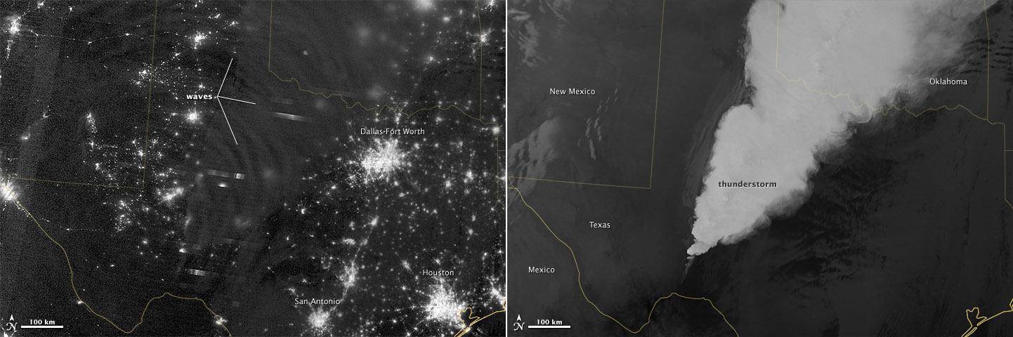
In April 2012, waves in Earth’s “airglow” spread across the nighttime skies of northern Texas like ripples in a pond. In this case, the waves were provoked by a massive thunderstorm. Airglow is a layer of nighttime light emissions caused by chemical reactions high in Earth’s atmosphere. A variety of reactions involving oxygen, sodium, ozone and nitrogen result in the production of a very faint amount of light. In fact, it’s approximately one billion times fainter than sunlight (~10-11 to 10-9 W·cm-2· sr-1). This chemiluminescence is similar to the chemical reactions that light up a glow stick or glow-in-the-dark silly putty. The “day-night band,” of the Visible Infrared Imaging Radiometer Suite (VIIRS) on the Suomi NPP satellite captured these glowing ripples in the night sky on April 15, 2012 (top image). The day-night band detects lights over a range of wavelengths from green to near-infrared and uses highly sensitive electronics to observe low light signals. (The absolute minimum signals detectable are at the levels of nightglow emission.) The lower image shows the thunderstorm as observed by a thermal infrared band on VIIRS. This thermal band, which is sensitive only to heat emissions (cold clouds appear white), is not sensitive to the subtle visible-light wave structures seen by the day-night band. Technically speaking, airglow occurs at all times. During the day it is called “dayglow,” at twilight “twilightglow,” and at night “nightglow.” There are slightly different processes taking place in each case, but in the image above the source of light is nightglow. The strongest nightglow emissions are mostly constrained to a relatively thin layer of atmosphere between 85 and 95 kilometers (53 and 60 miles) above the Earth’s surface. Little emission occurs below this layer since there’s a higher concentration of molecules, allowing for dissipation of chemical energy via collisions rather than light production. Likewise, little emission occurs above that layer because the atmospheric density is so tenuous that there are too few light-emitting reactions to yield an appreciable amount of light. Suomi NPP is in orbit around Earth at 834 kilometers (about 518 miles), well above the nightglow layer. The day-night band imagery therefore contains signals from the direction upward emission of the nightglow layer and the reflection of the downward nightglow emissions by clouds and the Earth’s surface. The presence of these nightglow waves is a graphic visualization of the usually unseen energy transfer processes that occur continuously between the lower and upper atmosphere. While nightglow is a well-known phenomenon, it’s not typically considered by Earth-viewing meteorological sensors. In fact, scientists were surprised at Suomi NPP’s ability to detect it. During the satellite’s check-out procedure, this unanticipated source of visible light was thought to indicate a problem with the sensor until scientists realized that what they were seeing was the faintest of light in the darkness of night. NASA Earth Observatory image by Jesse Allen and Robert Simmon, using VIIRS Day-Night Band data from the Suomi National Polar-orbiting Partnership. Suomi NPP is the result of a partnership between NASA, the National Oceanic and Atmospheric Administration, and the Department of Defense. Caption by Aries Keck and Steve Miller. Instrument: Suomi NPP - VIIRS Credit: <b><a href="http://www.earthobservatory.nasa.gov/" rel="nofollow"> NASA Earth Observatory</a></b> <b>Click here to view all of the <a href="http://earthobservatory.nasa.gov/Features/NightLights/" rel="nofollow"> Earth at Night 2012 images </a></b> <b>Click here to <a href="http://earthobservatory.nasa.gov/NaturalHazards/view.php?id=79817" rel="nofollow"> read more </a> about this image </b> <b><a href="http://www.nasa.gov/audience/formedia/features/MP_Photo_Guidelines.html" rel="nofollow">NASA image use policy.</a></b> <b><a href="http://www.nasa.gov/centers/goddard/home/index.html" rel="nofollow">NASA Goddard Space</a></b>