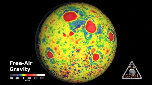
GRAIL Gravity Tour of the Moon
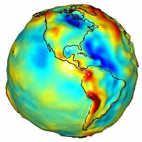
This visualization of a gravity model was created with data from NASA Gravity Recovery and Climate Experiment GRACE and shows variations in Earth’s gravity field.
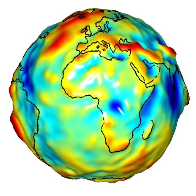
This visualization of a gravity model was created with data from NASA’s Gravity Recovery and Climate Experiment and shows variations in the gravity field across Africa and Europe.
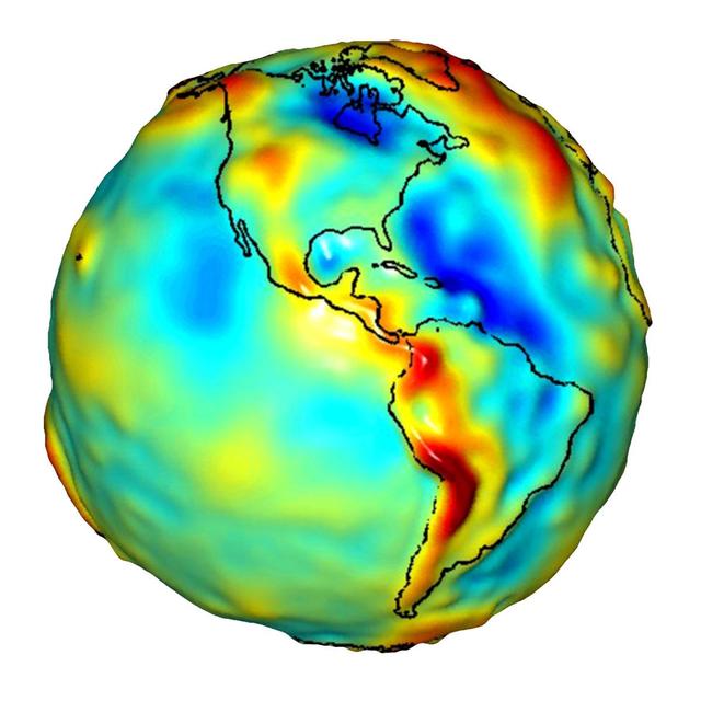
This visualization of a gravity model was created with data from NASA Gravity Recovery and Climate Experiment and shows variations in the gravity field across the Americas.
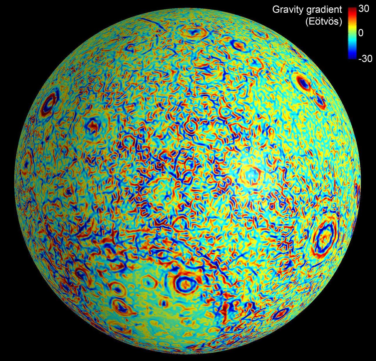
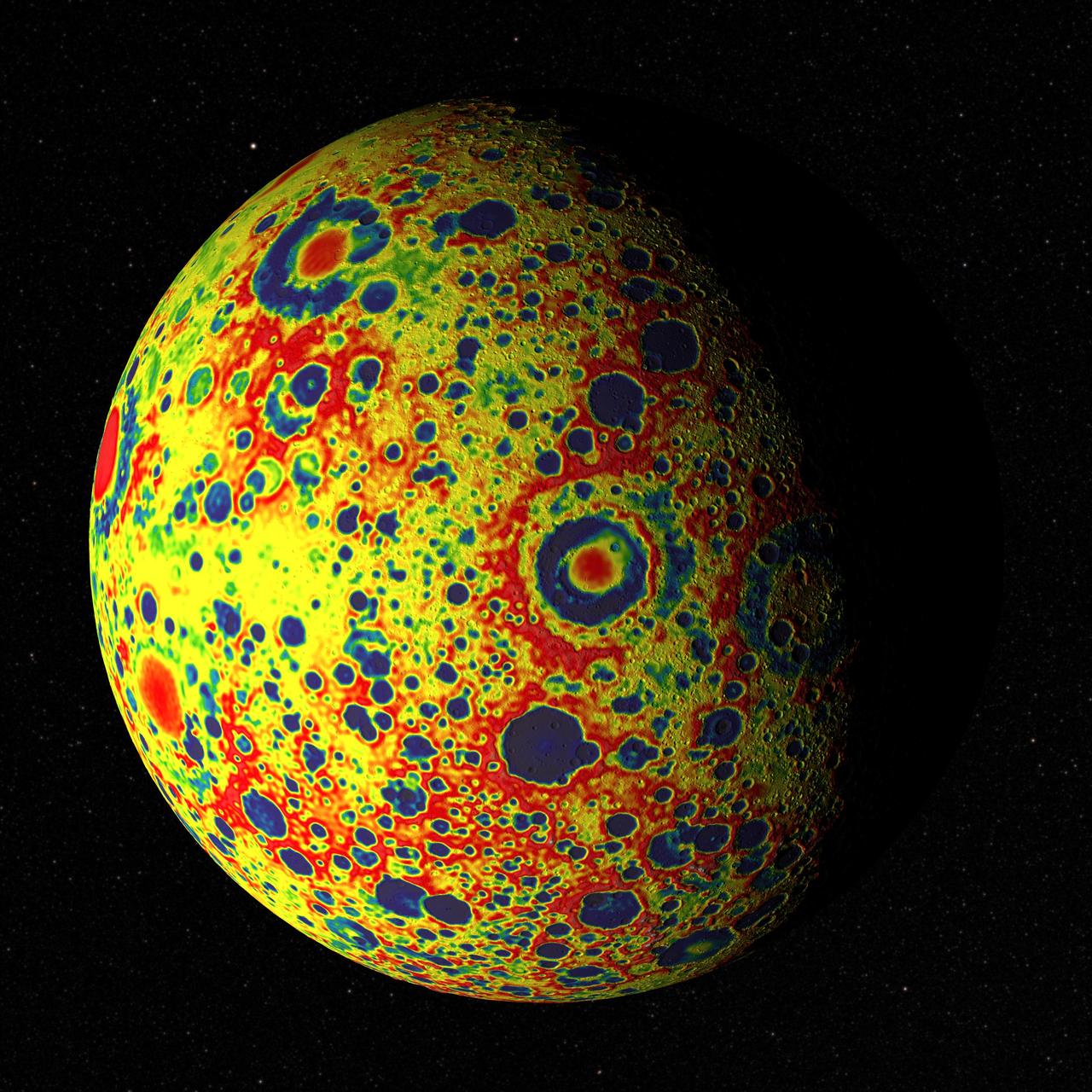
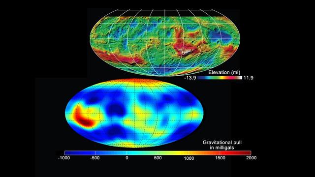
This moon map shows the gravity gradients calculated by NASA GRAIL mission. Red and blue correspond to stronger gravity gradients.
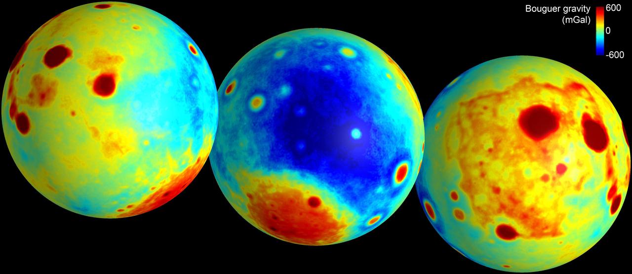
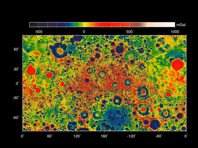
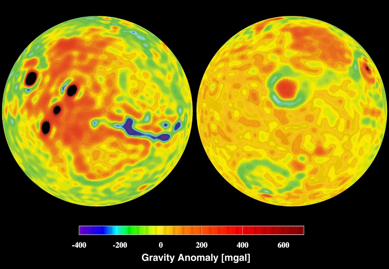
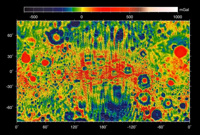
These maps of the moon show the Bouguer gravity anomalies as measured by NASA GRAIL mission. Red areas have stronger gravity, while blue areas have weaker gravity.
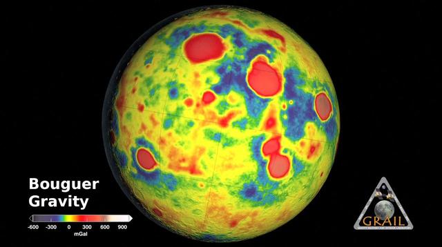
GRAIL Bouguer Gravity Moon Map
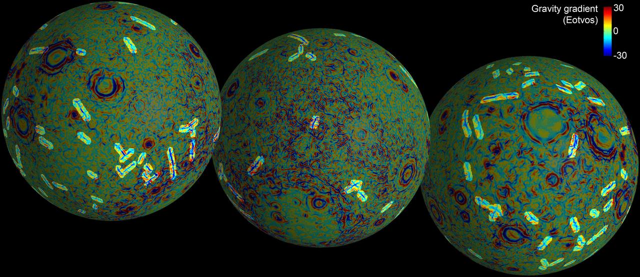
These maps of the near and far side of the moon show the gravity gradients as measured by NASA GRAIL mission, highlighting a population of linear gravity anomalies.
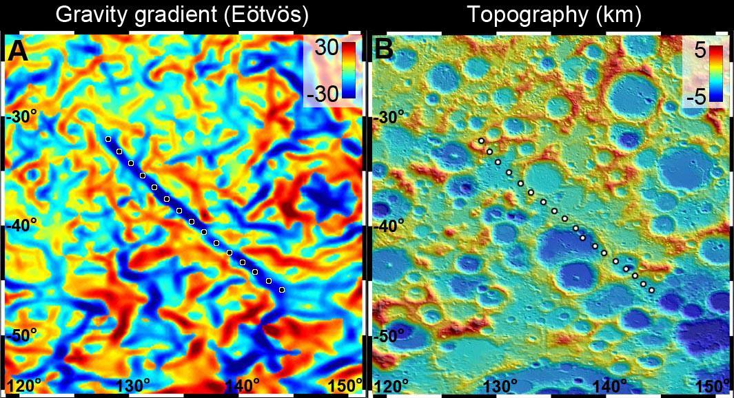
A 300-mile-long linear gravity anomaly on the far side of the moon has been revealed by gravity gradients measured by NASA GRAIL mission. GRAIL data are shown on the left, with red and blue corresponding to stronger gravity gradients.
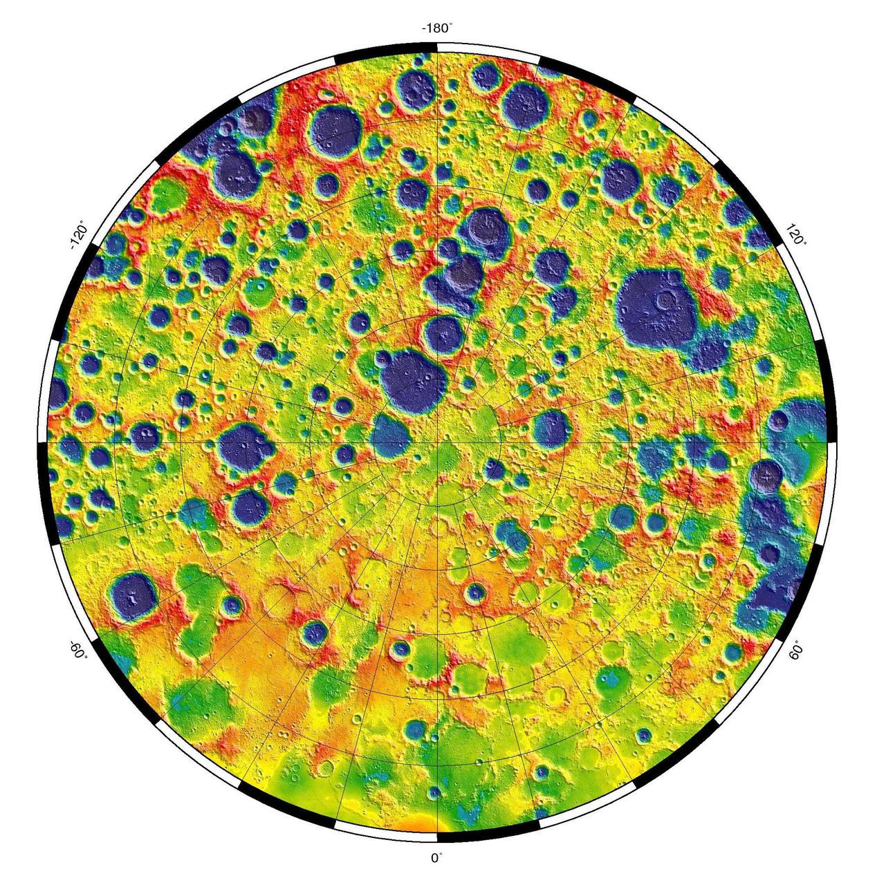
This is a polar stereographic map of gravity of the north polar region of the moon from the Gravity Recovery and Interior Laboratory GRAIL mission. The map displays the region from latitude 60 north to the pole.

Gravity of the Situation
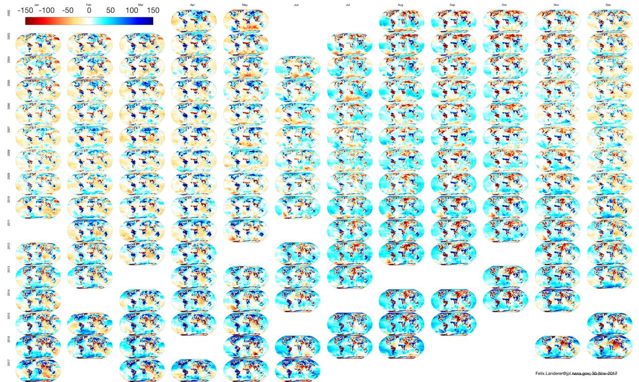
NASA's GRACE mission produced maps of anomalies in Earth's gravity field almost every month from April 2002 to June 2017. https://photojournal.jpl.nasa.gov/catalog/PIA22448
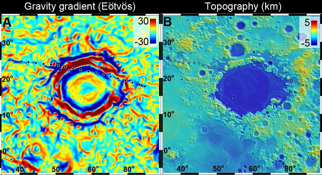
A linear gravity anomaly intersecting the Crisium basin on the nearside of the moon has been revealed by NASA GRAIL mission. The GRAIL gravity gradient data are shown at left, with the location of the anomaly indicated.
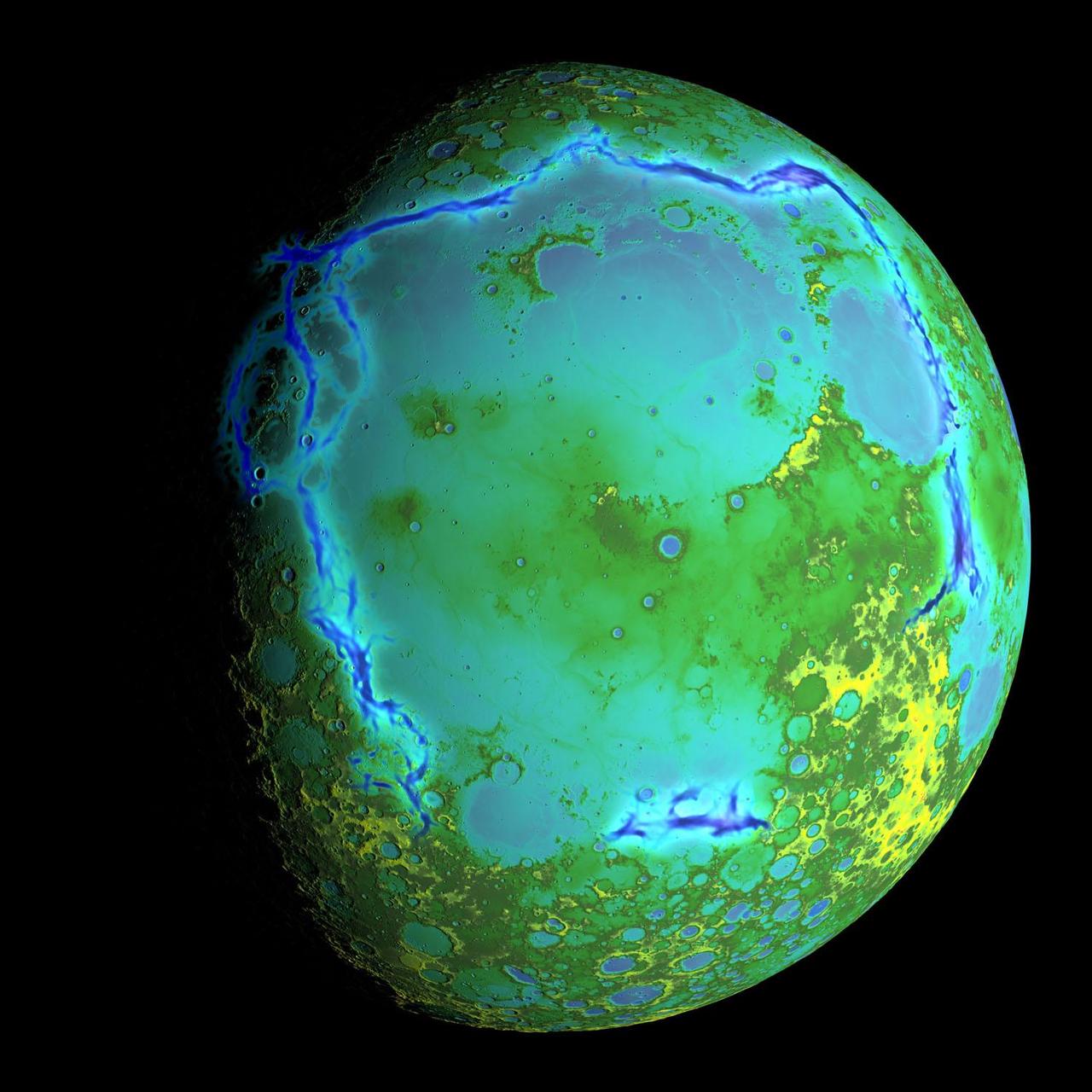
Topography of Earth moon generated from data NASA LRO, with the gravity anomalies bordering the Procellarum region superimposed in blue. The border structures are shown using gravity gradients calculated with data from NASA GRAIL mission.
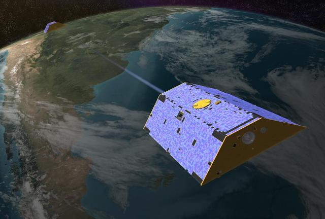
Artist concept of the Gravity Recovery and Climate Experiment GRACE from December 2002. http://photojournal.jpl.nasa.gov/catalog/PIA04236

Gravity is the force that is responsible for the weight of an object and is determined by how the material that makes up the Earth is distributed throughout the Earth.
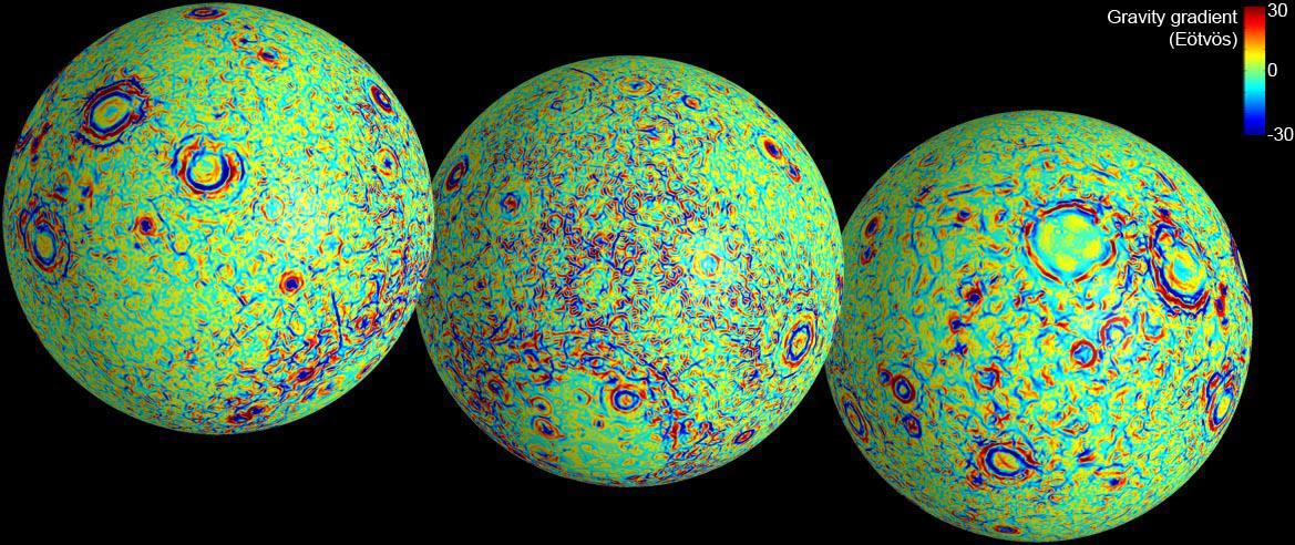
These maps of the near and far side of the moon show gravity gradients as measured by NASA GRAIL mission. Red and blue areas indicate stronger gradients due to underlying mass anomalies.
This map shows the gravity field of the moon as measured by NASA GRAIL mission. The viewing perspective, known as a Mercator projection, shows the far side of the moon in the center and the nearside as viewed from Earth at either side.
Feeling Gravity Pull
Mars Gravity Anomoly Map
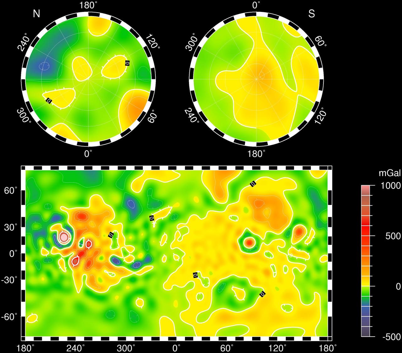
Mars Gravity Map RS
Gravity-Induced Undulations
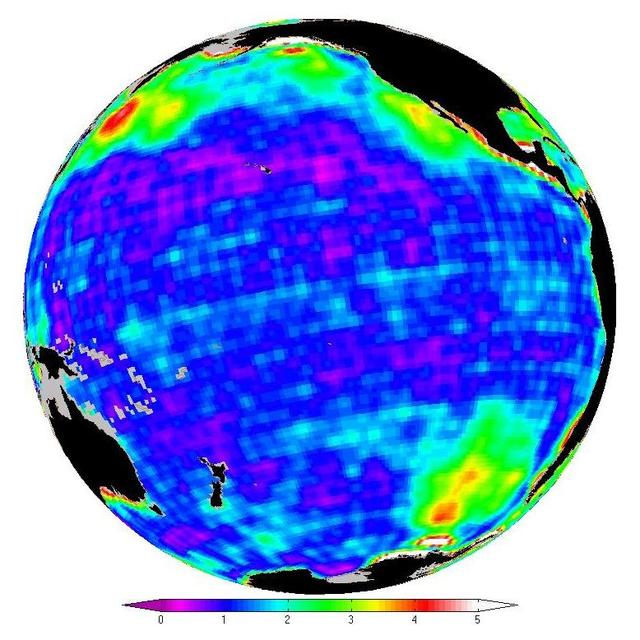
This map shows changes in ocean bottom pressure measured by NASA Gravity Recovery and Climate Experiment.
This map shows the gravity field of the moon from the Lunar Prospector mission. The viewing perspective, known as a Mercator projection, shows the far side of the moon in the center and the nearside as viewed from Earth at either side.
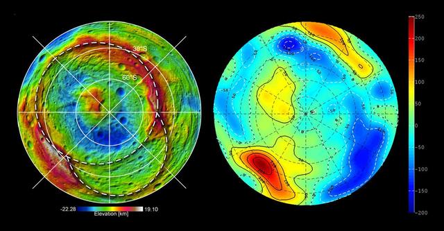
This still image features a free-air gravity map of the Moon's southern latitudes developed by S. Goossens et al. from data returned by the Gravity Recovery and Interior Laboratory (GRAIL) mission. If the Moon were a perfectly smooth sphere of uniform density, the gravity map would be a single, featureless color, indicating that the force of gravity at a given elevation was the same everywhere. But like other rocky bodies in the solar system, including Earth, the Moon has both a bumpy surface and a lumpy interior. Spacecraft in orbit around the Moon experience slight variations in gravity caused by both of these irregularities. The free-air gravity map shows deviations from the mean gravity that a cueball Moon would have. The deviations are measured in milliGals, a unit of acceleration. On the map, purple is at the low end of the range, at around -400 mGals, and red is at the high end near +400 mGals. Yellow denotes the mean. The map shown here extends from the south pole of the Moon up to 50°S and reveals the gravity for that region in even finer detail than the global gravity maps published previously. The image illustrates the very good correlation between the gravity map and topographic features such as peaks and craters, as well as the mass concentration lying beneath the large Schrödinger basin in the center of the frame. The terrain in the image is based on Lunar Reconnaissance Orbiter (LRO) altimeter and camera data. Credit: NASA's Scientific Visualization Studio <b><a href="http://www.nasa.gov/audience/formedia/features/MP_Photo_Guidelines.html" rel="nofollow">NASA image use policy.</a></b> <b><a href="http://www.nasa.gov/centers/goddard/home/index.html" rel="nofollow">NASA Goddard Space Flight Center</a></b> enables NASA’s mission through four scientific endeavors: Earth Science, Heliophysics, Solar System Exploration, and Astrophysics. Goddard plays a leading role in NASA’s accomplishments by contributing compelling scientific knowledge to advance the Agency’s mission. <b>Follow us on <a href="http://twitter.com/NASAGoddardPix" rel="nofollow">Twitter</a></b> <b>Like us on <a href="http://www.facebook.com/pages/Greenbelt-MD/NASA-Goddard/395013845897?ref=tsd" rel="nofollow">Facebook</a></b> <b>Find us on <a href="http://instagram.com/nasagoddard?vm=grid" rel="nofollow">Instagram</a></b>
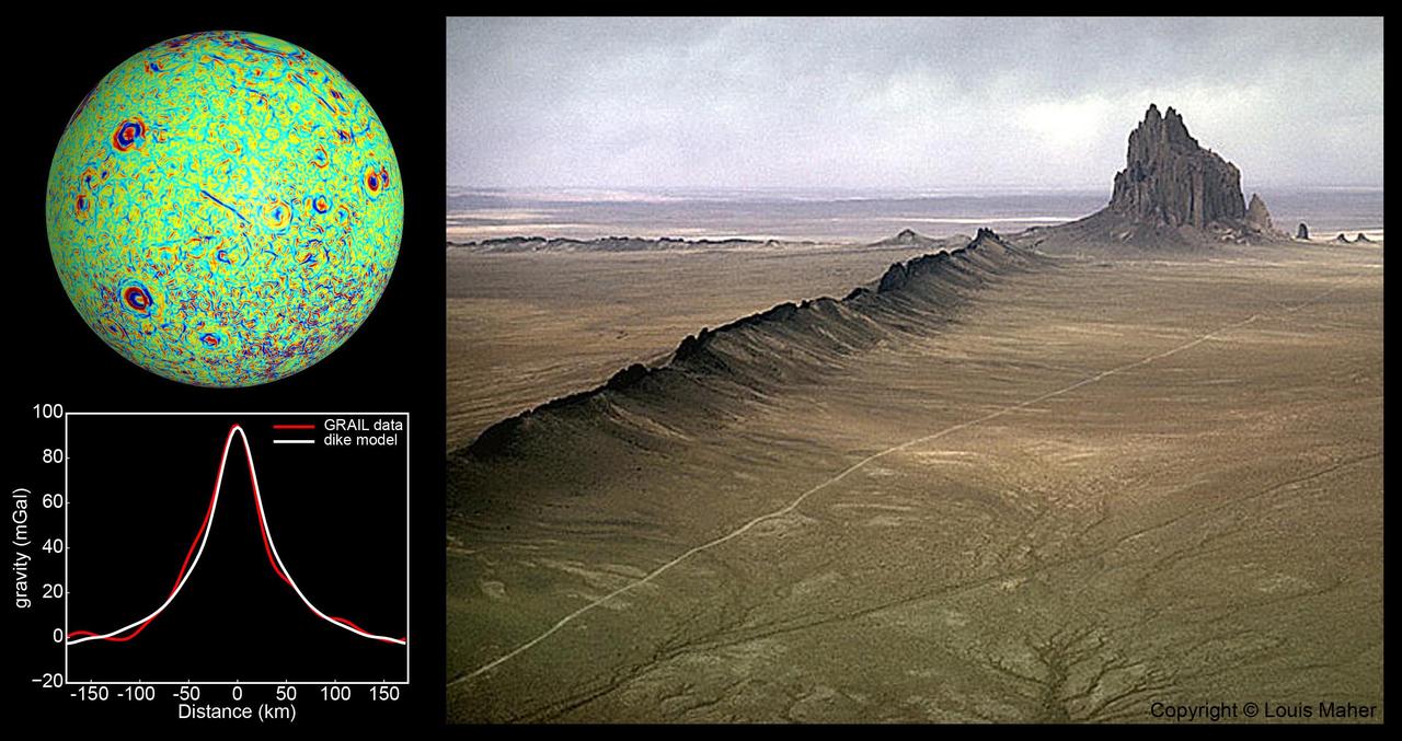
A profile across one of the linear gravity anomalies found by NASA GRAIL mission shows that it has higher gravity than the surroundings.
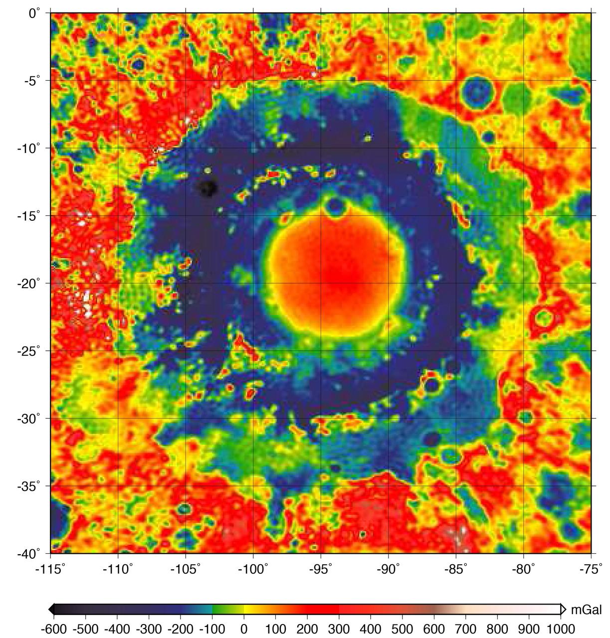
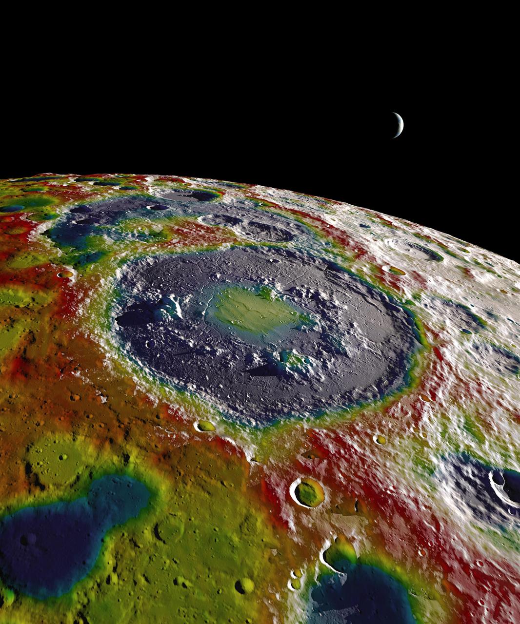
This color-coded map shows the strength of surface gravity around Orientale basin on Earth's moon, derived from data obtained by NASA's GRAIL mission. The GRAIL mission produced a very high-resolution map of gravity over the surface of the entire moon. This plot is zoomed in on the part of that map that features Orientale basin, where the two GRAIL spacecraft flew extremely low near the end of their mission. Their close proximity to the basin made the probes' measurements particularly sensitive to the gravitational acceleration there (due to the inverse squared law). The color scale plots the gravitational acceleration in units of "gals," where 1 gal is one centimeter per second squared, or about 1/1000th of the gravitational acceleration at Earth's surface. (The unit was devised in honor of the astronomer Galileo). Labels on the x and y axes represent latitude and longitude. http://photojournal.jpl.nasa.gov/catalog/PIA21050
If the Moon were a perfectly smooth sphere of uniform density, the gravity map would be a single, featureless color, indicating that the force of gravity at a given elevation was the same everywhere. But like other rocky bodies in the solar system, including Earth, the Moon has both a bumpy surface and a lumpy interior. Spacecraft in orbit around the Moon experience slight variations in gravity caused by both of these irregularities. The free-air gravity map shows deviations from the mean, the gravity that a cueball Moon would have. The deviations are measured in milliGals, a unit of acceleration. On the map, dark purple is at the low end of the range, at around -400 mGals, and red is at the high end near +400 mGals. Yellow denotes the mean. These views show a part of the Moon's surface that's never visible from Earth. They are centered on lunar coordinates 29°N 142°E. The large, multi-ringed impact feature near the center is Mare Moscoviense. The crater Mendeleev is south of this. The digital elevation model for the terrain is from the Lunar Reconnaissance Orbiter laser altimeter (LOLA). Merely for plausibility, the sun angle and starry background are accurate for specific dates (December 21, 2012, 0:00 UT and January 8, 2013, 14:00 UT, respectively). To see or download more views go to: <a href="http://svs.gsfc.nasa.gov/goto?4041" rel="nofollow">svs.gsfc.nasa.gov/goto?4041</a> Credit: NASA's Goddard Goddard Space Flight Center Scientific Visualization Studio <b><a href="http://www.nasa.gov/audience/formedia/features/MP_Photo_Guidelines.html" rel="nofollow">NASA image use policy.</a></b> <b><a href="http://www.nasa.gov/centers/goddard/home/index.html" rel="nofollow">NASA Goddard Space Flight Center</a></b> enables NASA’s mission through four scientific endeavors: Earth Science, Heliophysics, Solar System Exploration, and Astrophysics. Goddard plays a leading role in NASA’s accomplishments by contributing compelling scientific knowledge to advance the Agency’s mission. <b>Follow us on <a href="http://twitter.com/NASA_GoddardPix" rel="nofollow">Twitter</a></b> <b>Like us on <a href="http://www.facebook.com/pages/Greenbelt-MD/NASA-Goddard/395013845897?ref=tsd" rel="nofollow">Facebook</a></b> <b>Find us on <a href="http://instagram.com/nasagoddard?vm=grid" rel="nofollow">Instagram</a></b>
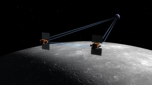
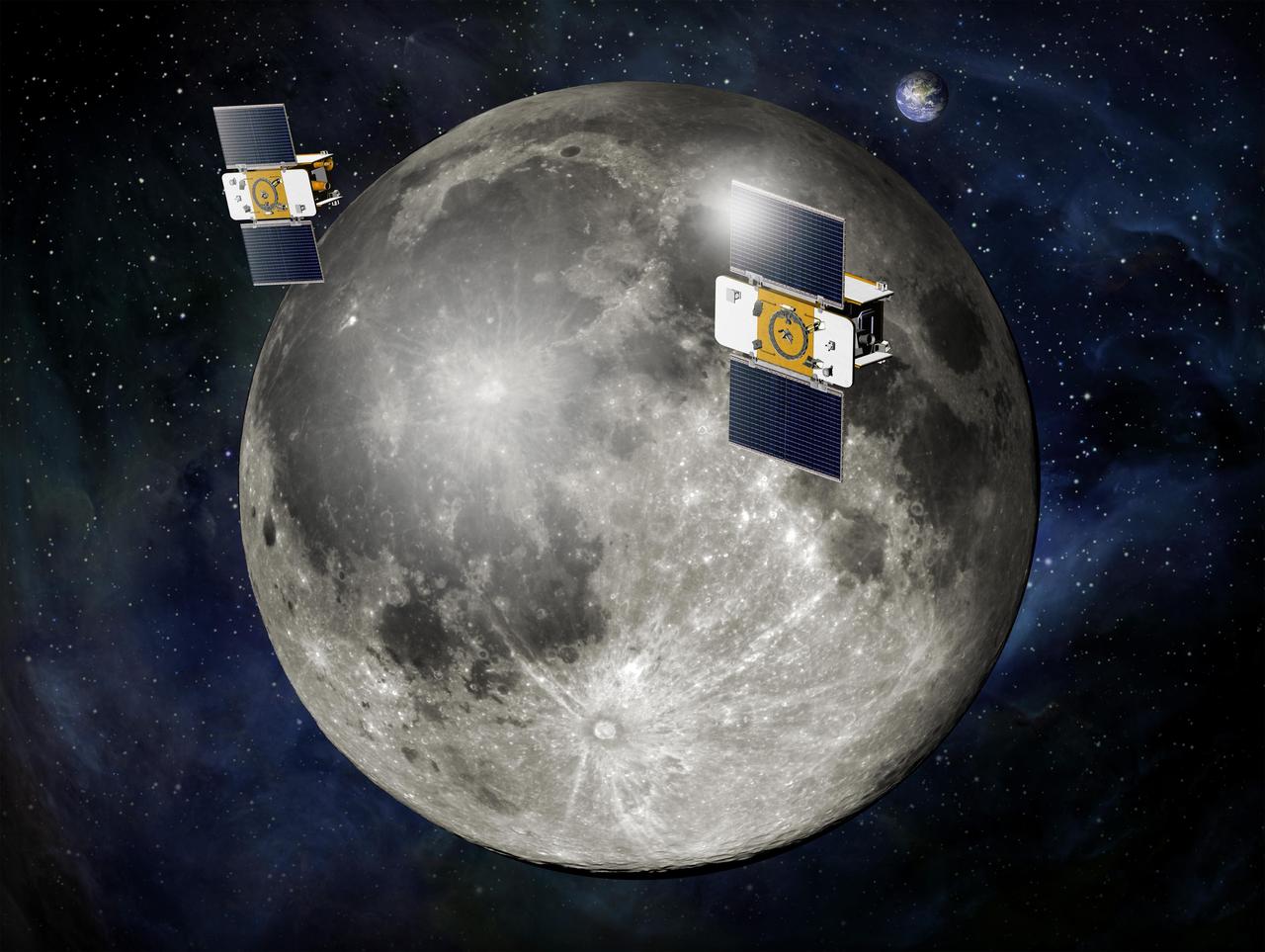
The Gravity Recovery and Interior Laboratory, or GRAIL, mission will fly twin spacecraft in tandem orbits around the moon to measure its gravity field in unprecedented detail. GRAIL is a part of NASA Discovery Program.
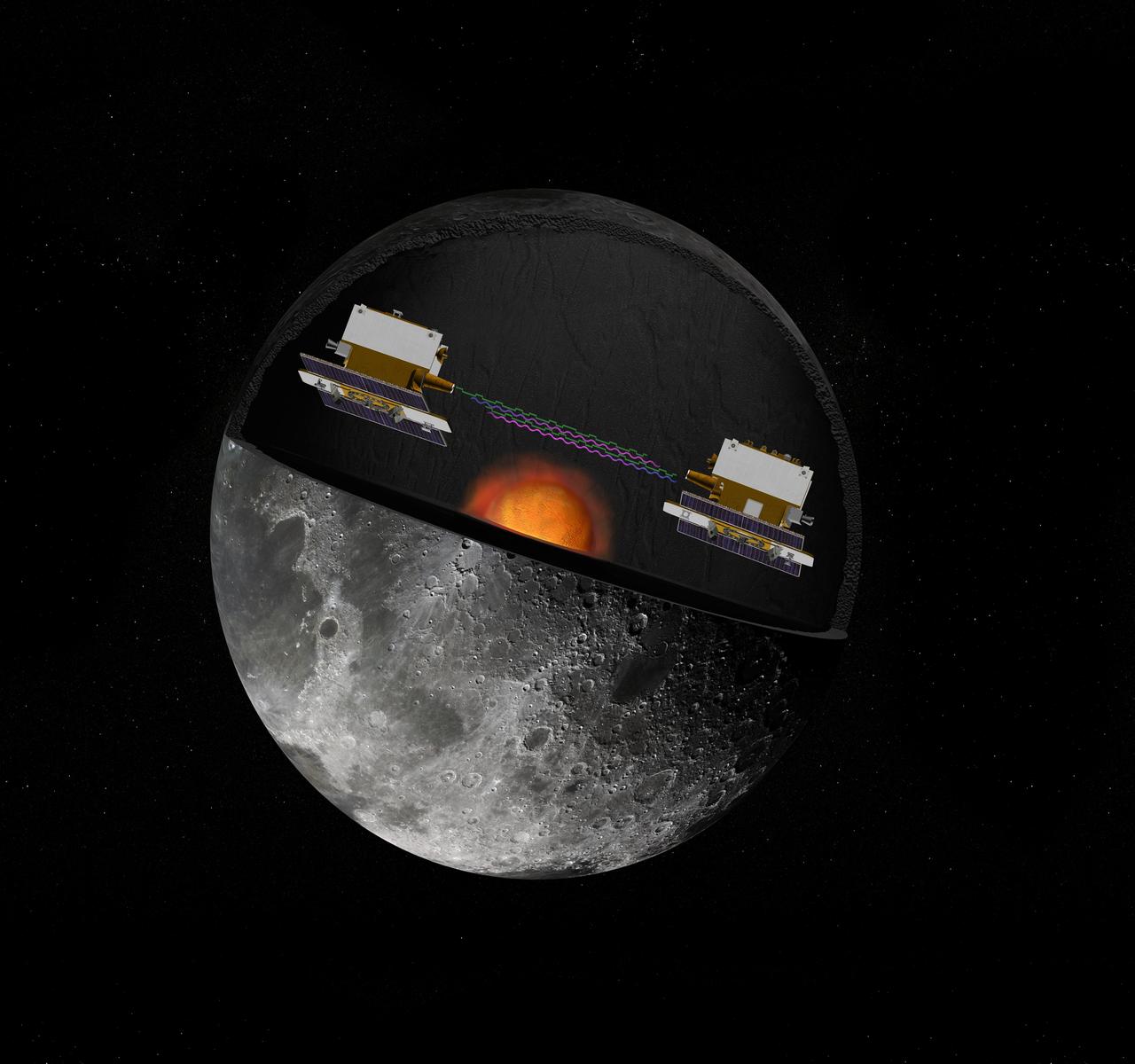
The Gravity Recovery and Interior Laboratory GRAIL mission utilizes the technique of twin spacecraft flying in formation with a known altitude above the lunar surface and known separation distance to investigate the gravity field of the moon.
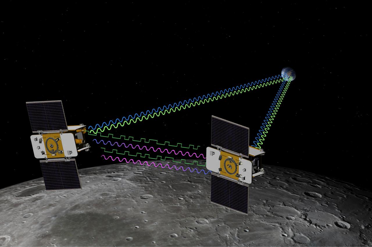
The Gravity Recovery and Interior Laboratory GRAIL mission utilizes the technique of twin spacecraft flying in formation with a known altitude above the lunar surface and known separation distance to investigate the gravity field of the moon.
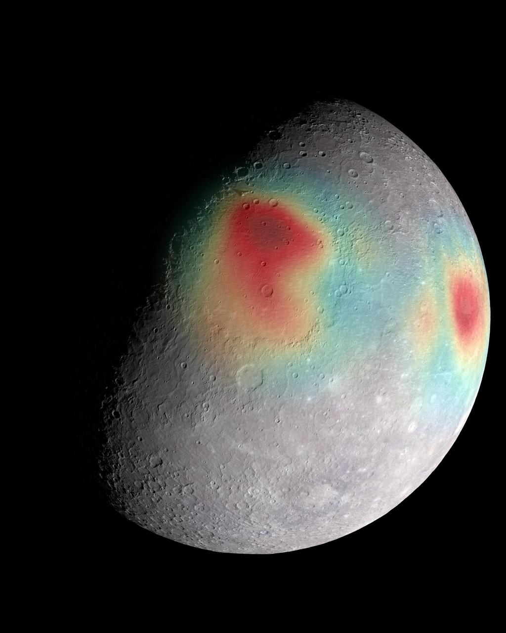
Analysis of radio tracking data have enabled maps of the gravity field of Mercury to be derived. In this image, overlain on a mosaic obtained by MESSENGER's Mercury Dual Imaging System and illuminated with a shape model determined from stereo-photoclinometry, Mercury's gravity anomalies are depicted in colors. Red tones indicate mass concentrations, centered on the Caloris basin (center) and the Sobkou region (right limb). Such large-scale gravitational anomalies are signatures of subsurface structure and evolution. The north pole is near the top of the sunlit area in this view. http://photojournal.jpl.nasa.gov/catalog/PIA19285
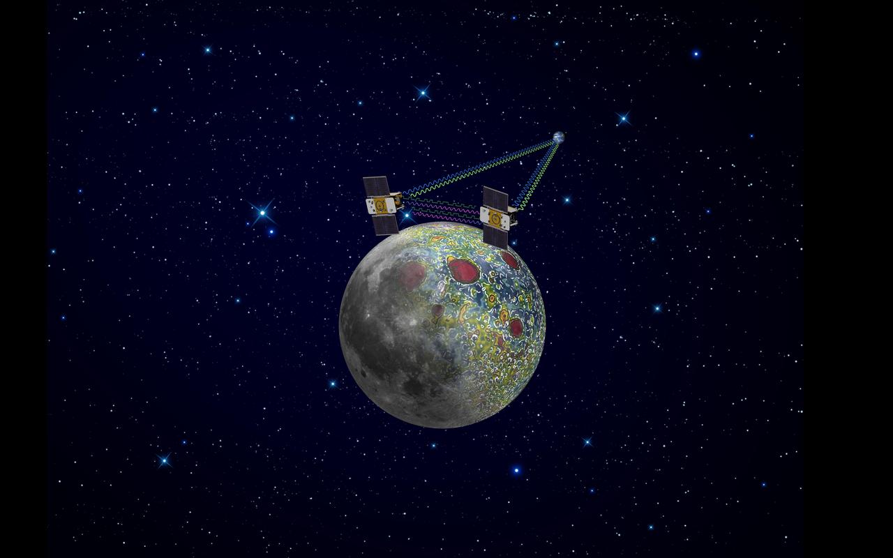
Using a precision formation-flying technique, the twin GRAIL spacecraft maps the moon gravity field, as depicted in this artist rendering.
Using a precision formation-flying technique, NASA twin GRAIL spacecraft will map the moon gravity field. This is an artist concept.
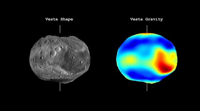
This image from NASA Dawn mission shows topography of the giant asteroid Vesta and a map of Vesta gravity variations.
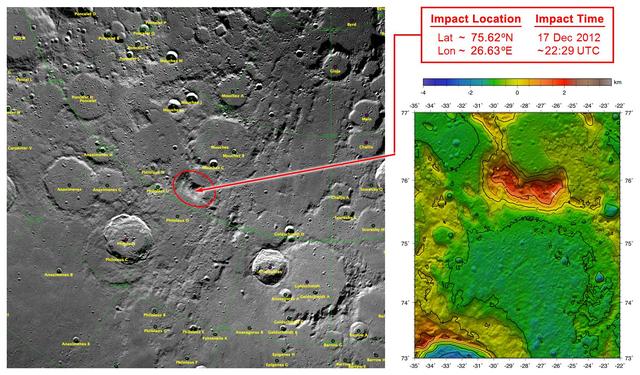
These maps of Earth moon highlight the region where the twin spacecraft of NASA Gravity Recovery and Interior Laboratory GRAIL mission will impact on Dec. 17, marking the end of its successful endeavor to map the moon gravity.
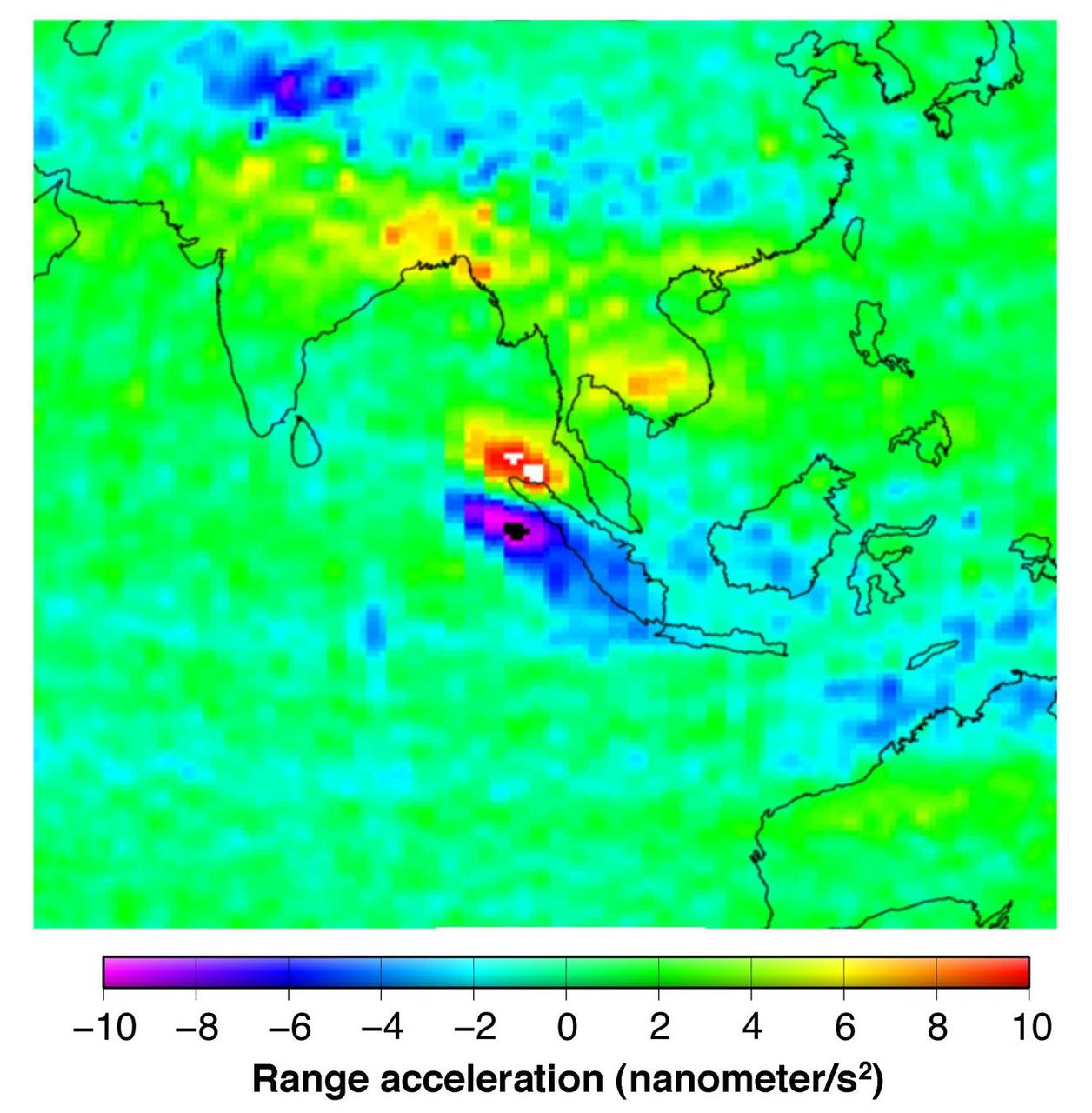
This figure shows the effect of the December 2004 great Sumatra earthquake on the Earth’s gravity field as observed by NASA GRACE.
ZERO GRAVITY AIRCRAFT KC135 FLIGHTS AT LEWIS RESEARCH CENTER (Glenn Research Center)
This frame from a video from NASA Dawn mission shows that the gravity field of Vesta closely matches the surface topography of the giant asteroid Vesta.
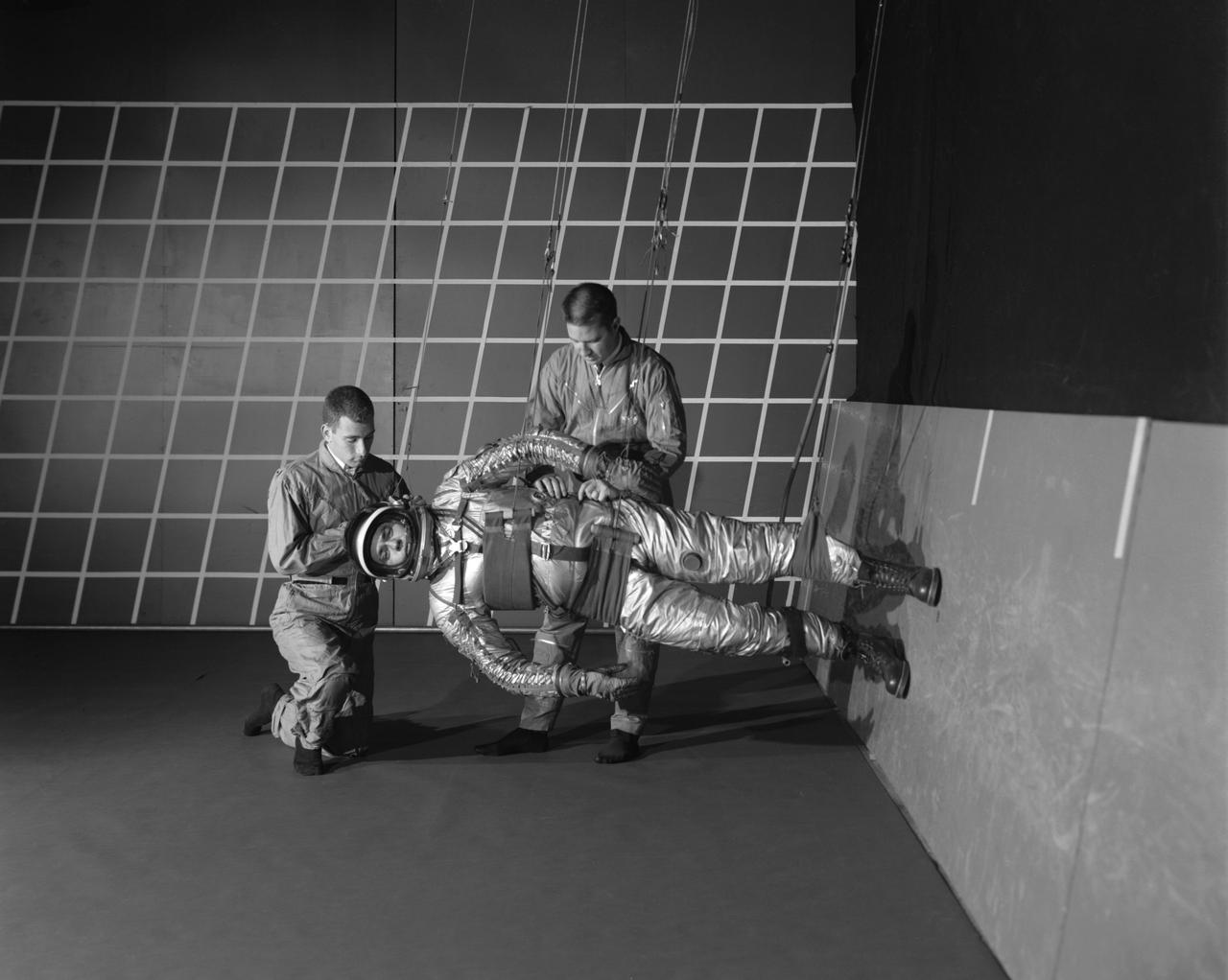
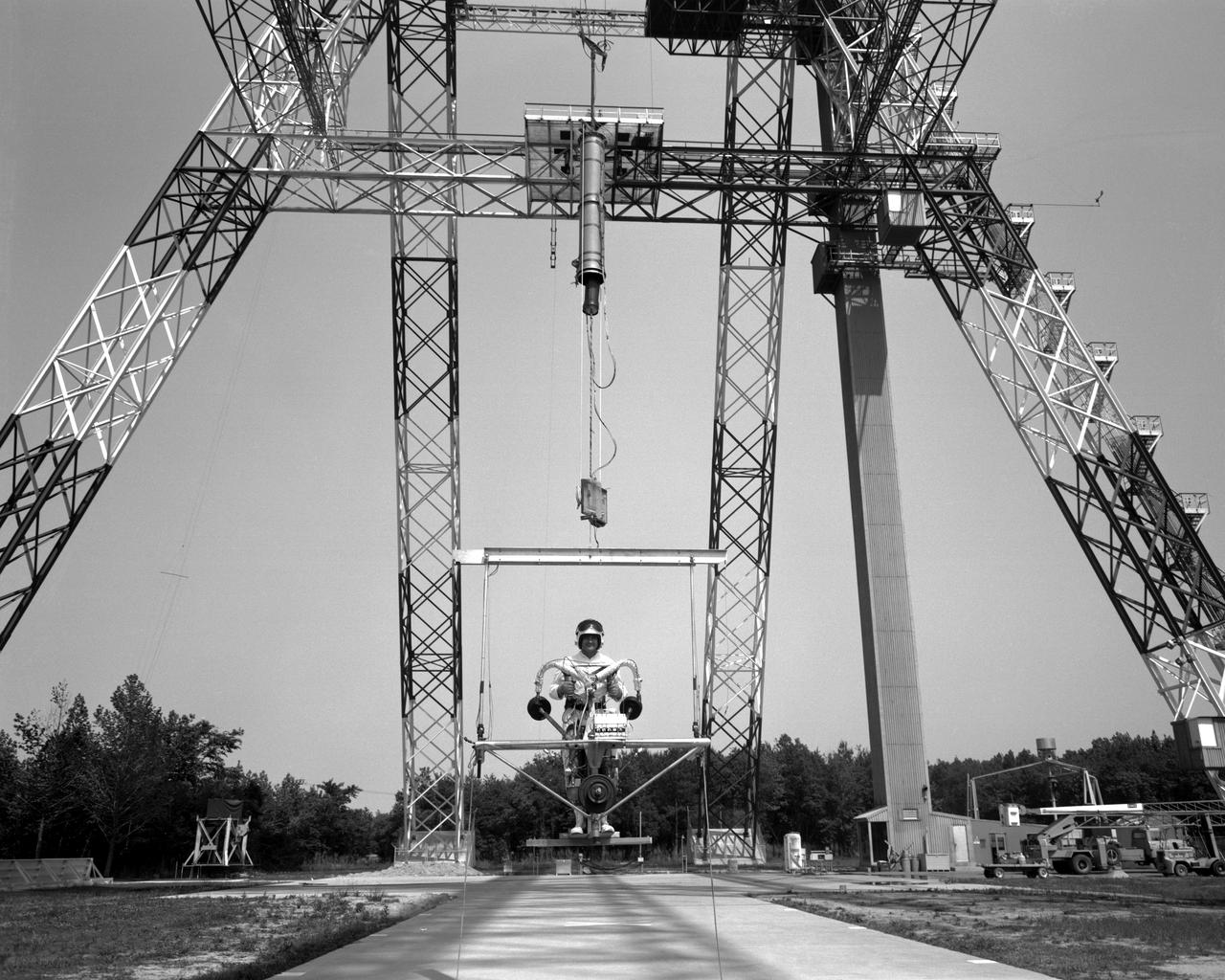
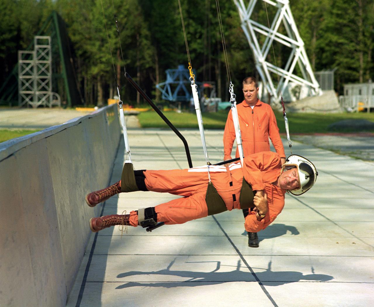
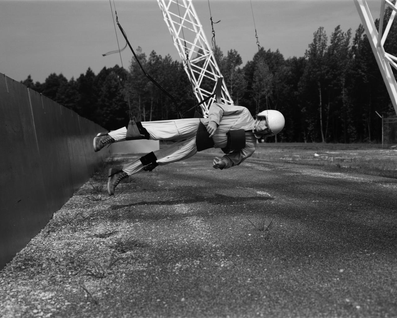
A test subject being suited up for studies on the Reduced Gravity Walking Simulator located in the hangar at Langley Research Center. The initial version of this simulator was located inside the hangar. Later a larger version would be located at the Lunar Landing Facility. The purpose of this simulator was to study the subject while walking, jumping or running. Researchers conducted studies of various factors such as fatigue limit, energy expenditure, and speed of locomotion. Francis B. Smith wrote in his paper "Simulators For Manned Space Research," "I would like to conclude this talk with a discussion of a device for simulating lunar gravity which is very effective and yet which is so simple that its cost is in the order of a few thousand dollars at most, rather than hundreds of thousands. With a little ingenuity, one could almost build this type simulator in his backyard for children to play on. The principle is ...if a test subject is suspended in a sling so that his body axis makes an angle of 9 1/2 degrees with the horizontal and if he then "stands" on a platform perpendicular to his body axis, the component of the earth's gravity forcing him toward the platform is one times the sine of 9 1/2 degrees or approximately 1/6 of the earth's normal gravity field. That is, a 180 pound astronaut "standing" on the platform would exert a force of only 30 pounds - the same as if he were standing upright on the lunar surface." -- Published in James R. Hansen, Spaceflight Revolution: NASA Langley Research Center From Sputnik to Apollo, NASA SP-4308; Francis B. Smith, "Simulators For Manned Space Research," Paper for 1966 IEEE International Convention, New York, NY, March 21-25, 1966

Groundwater storage trends around the United States as measured by the NASA/German Aerospace Center Gravity Recovery and Climate Experiment GRACE satellites between 2003 and 2012.
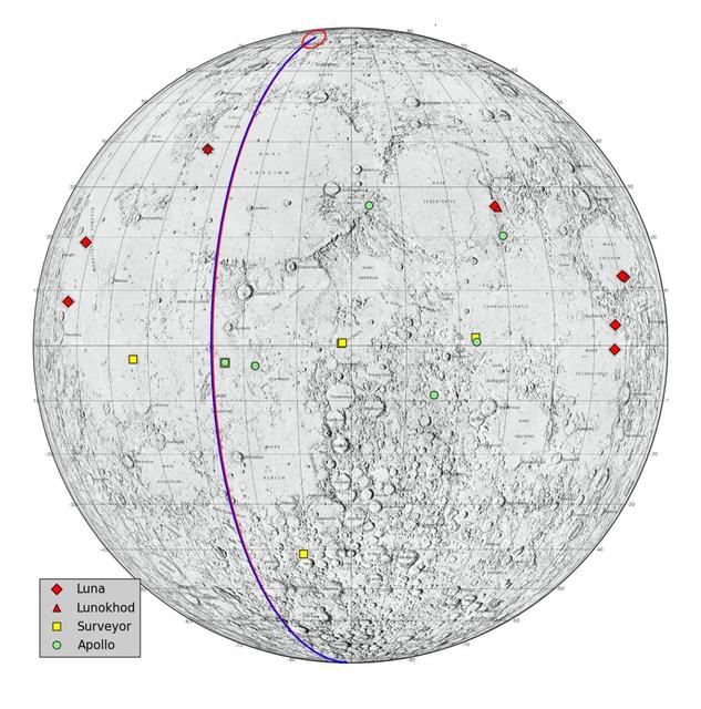
This graphic highlights locations on the moon NASA considers lunar heritage sites and the path NASA Gravity Recovery and Interior Laboratory spacecraft will take on their final flight.
ZERO GRAVITY AIRCRAFT KC135 FLIGHTS AT LEWIS RESEARCH CENTER
POGO is a device that uses cables connected to the ceiling to suspend an astronaut. POGO supports five-sixths of a person's weight; it mimics the one-sixth gravity of the moon. An astronaut walking around on POGO has the sensation of walking on the moon. POGO has been around since the Apollo days - in fact, the device gets its name from the way Apollo astronauts tended to bounce when suspended from it. The real name for POGO is the Partial Gravity Simulator.
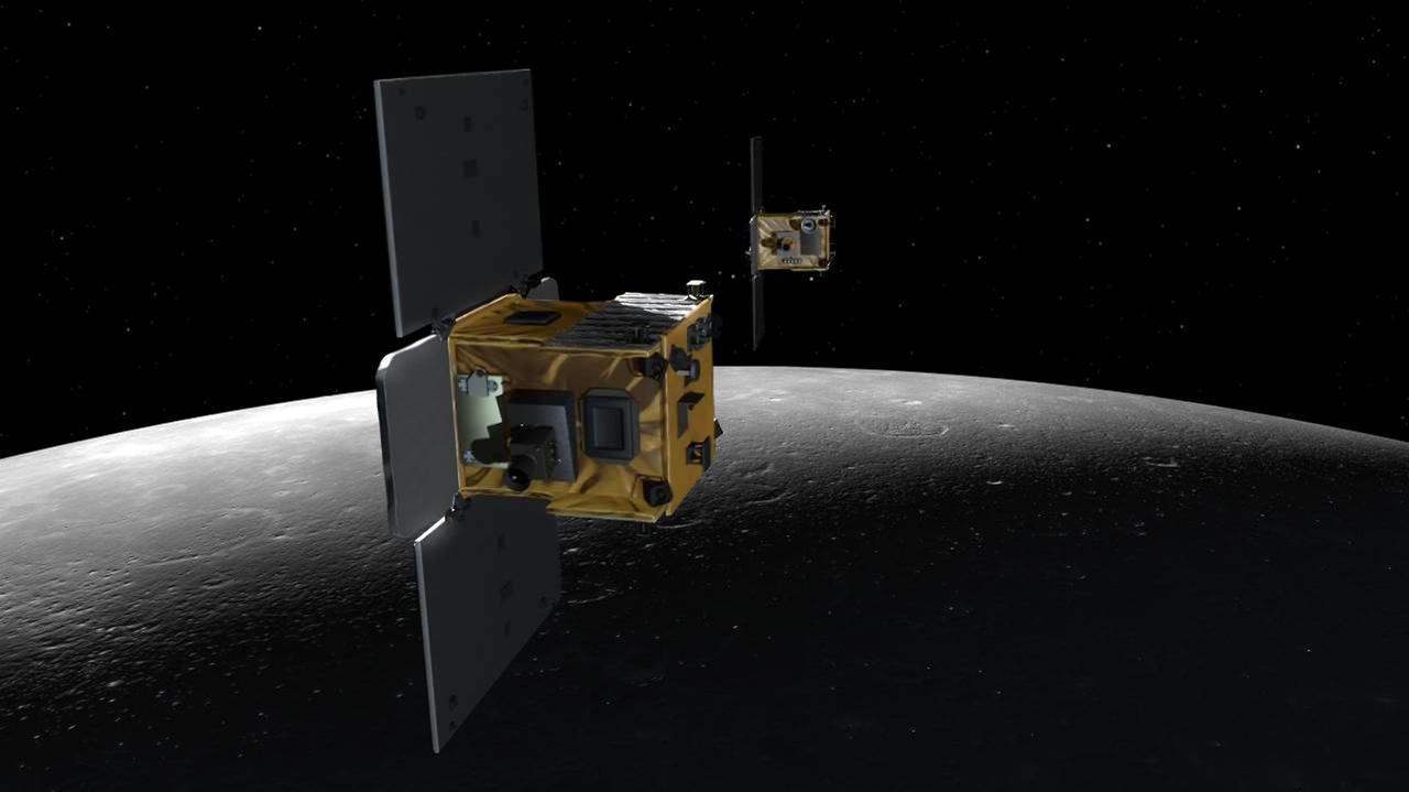
An artist depiction of the twin spacecraft Ebb and Flow that comprise NASA GRAIL mission. As Ebb and Flow fly over areas of greater and lesser gravity surface features can influence the distance between the two spacecraft.
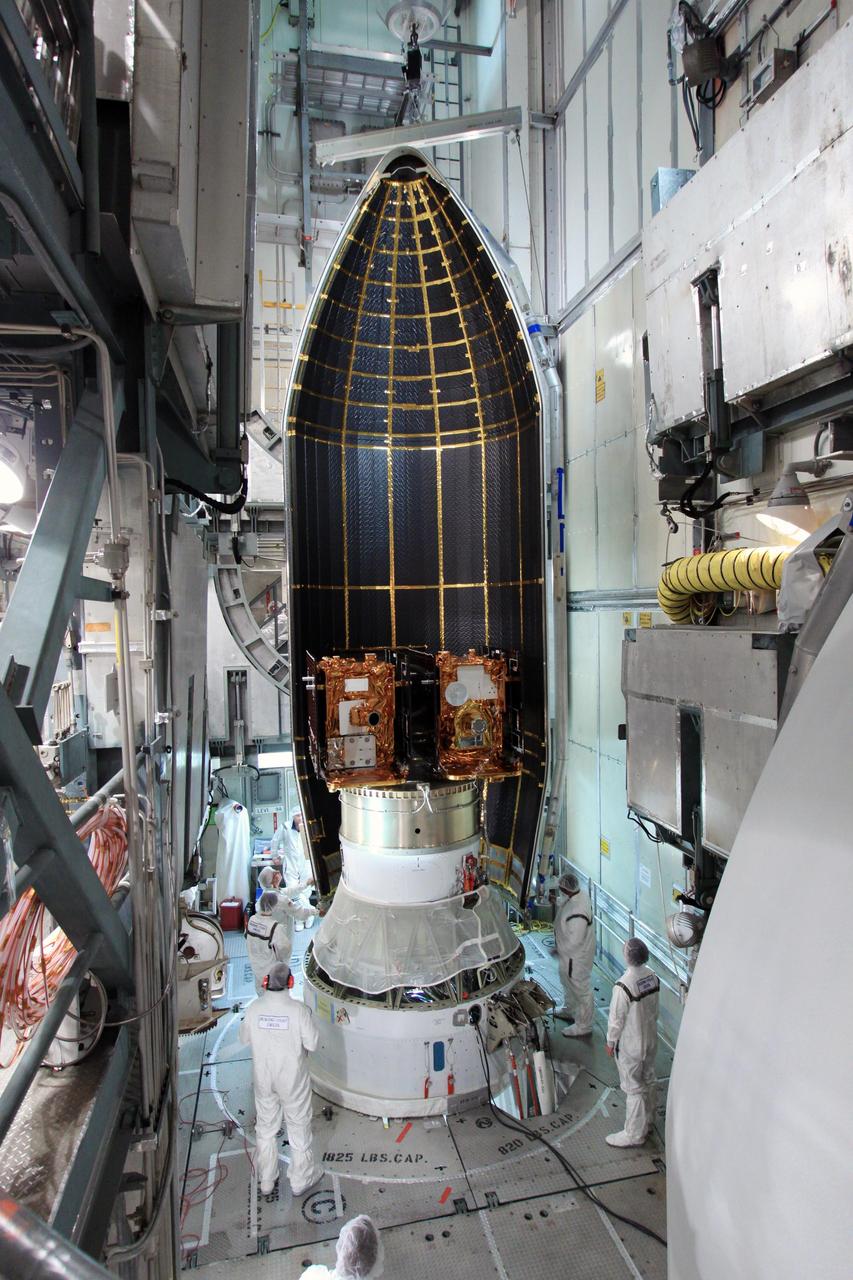
Spacecraft technicians monitor the movement of a section of the clamshell-shaped Delta payload fairing as it encloses NASA twin Gravity Recovery and Interior Laboratory spacecraft at Cape Canaveral Air Force Station in Florida on Aug. 23, 2011.
Reduced Gravity Walking Simulator located in the hangar at Langley Research Center. The initial version of this simulator was located inside the hangar. Later a larger version would be located at the Lunar Landing Facility. The purpose of this simulator was to study the subject while walking, jumping or running. Researchers conducted studies of various factors such as fatigue limit, energy expenditure, and speed of locomotion. A.W. Vigil wrote in his paper Discussion of Existing and Planned Simulators for Space Research, When the astronauts land on the moon they will be in an unfamiliar environment involving, particularly, a gravitational field only one-sixth as strong as on earth. A novel method of simulating lunar gravity has been developed and is supported by a puppet-type suspension system at the end of a long pendulum. A floor is provided at the proper angle so that one-sixth of the subject' s weight is supported by the floor with the remainder being supported by the suspension system. This simulator allows almost complete freedom in vertical translation and pitch and is considered to be a very realistic simulation of the lunar walking problem. For this problem this simulator suffers only slightly from the restrictions in lateral movement it puts on the test subject. This is not considered a strong disadvantage for ordinary walking problems since most of the motions do, in fact, occur in the vertical plane. However, this simulation technique would be severely restrictive if applied to the study of the extra-vehicular locomotion problem, for example, because in this situation complete six degrees of freedom are rather necessary. This technique, in effect, automatically introduces a two-axis attitude stabilization system into the problem. The technique could, however, be used in preliminary studies of extra-vehicular locomotion where, for example, it might be assumed that one axis of the attitude control system on the astronaut maneuvering unit may have failed. -- Published in James R. Hansen, Spaceflight Revolution: NASA Langley Research Center From Sputnik to Apollo, NASA SP-4308, p. 377 A.W. Vigil, Discussion of Existing and Planned Simulators for Space Research, Paper presented at Conference on the Role of Simulation in Space Technology, Blacksburg, VA, August 17-21, 1964.
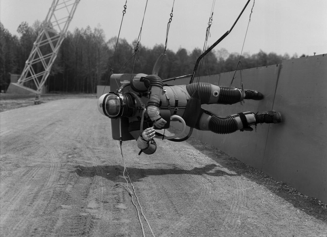
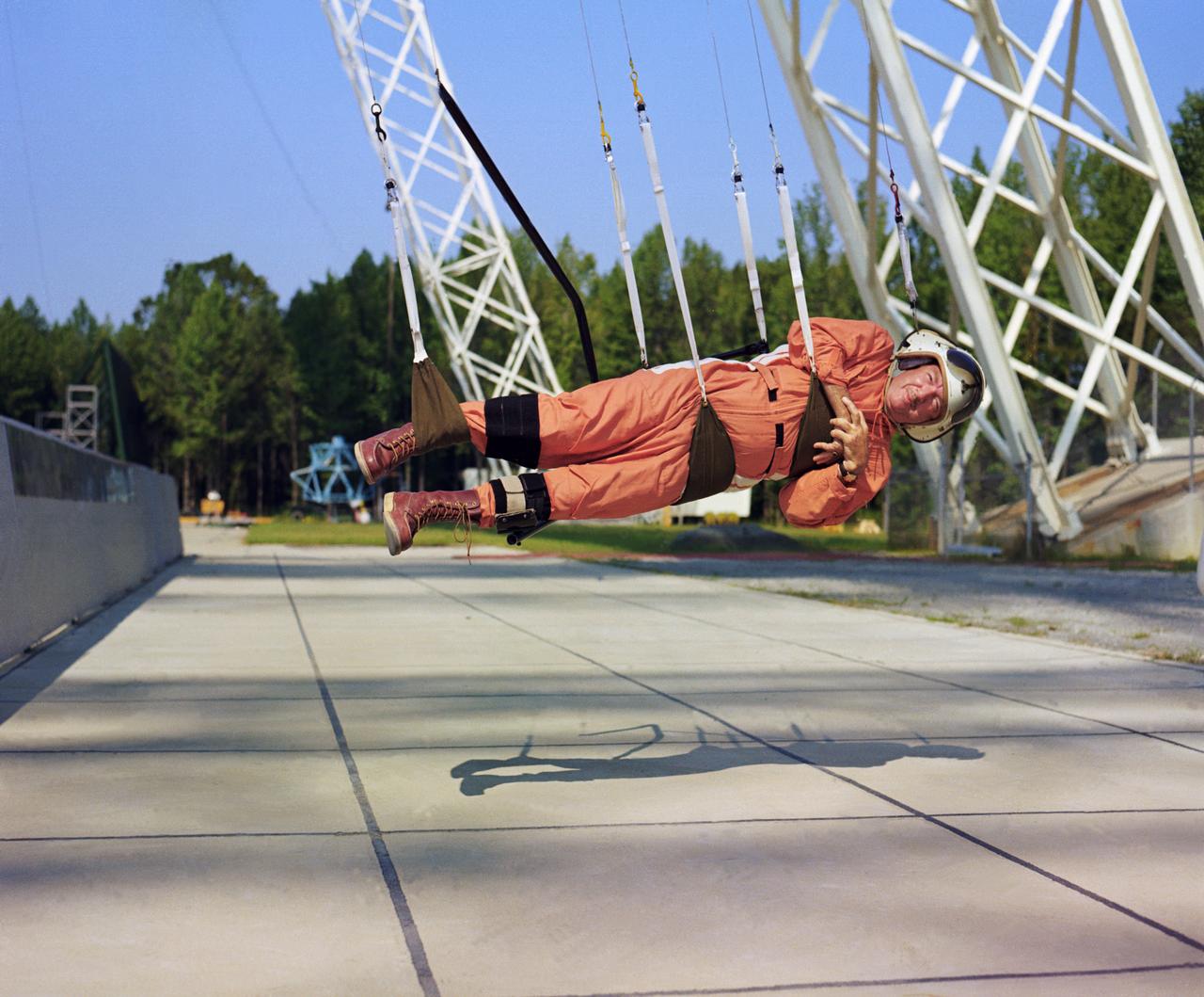
Test subject wearing the pressurized "space" suit for the Reduced Gravity Walking Simulator located at the Lunar Landing Facility. The purpose of this simulator was to study the subject while walking, jumping or running. Researchers conducted studies of various factors such as fatigue limit, energy expenditure, and speed of locomotion. A.W. Vigil described the purpose of the simulator in his paper "Discussion of Existing and Planned Simulators for Space Research," "When the astronauts land on the moon they will be in an unfamiliar environment involving, particularly, a gravitational field only one-sixth as strong as on earth. A novel method of simulating lunar gravity has been developed and is supported by a puppet-type suspension system at the end of a long pendulum. A floor is provided at the proper angle so that one-sixth of the subject's weight is supported by the floor with the remainder being supported by the suspension system. This simulator allows almost complete freedom in vertical translation and pitch and is considered to be a very realistic simulation of the lunar walking problem. For this problem this simulator suffers only slightly from the restrictions in lateral movement it puts on the test subject. This is not considered a strong disadvantage for ordinary walking problems since most of the motions do, in fact, occur in the vertical plane. However, this simulation technique would be severely restrictive if applied to the study of the extra-vehicular locomotion problem, for example, because in this situation complete six degrees of freedom are rather necessary. This technique, in effect, automatically introduces a two-axis attitude stabilization system into the problem. The technique could, however, be used in preliminary studies of extra-vehicular locomotion where, for example, it might be assumed that one axis of the attitude control system on the astronaut maneuvering unit may have failed." -- Published in James R. Hansen, Spaceflight Revolution: NASA Langley Research Center From Sputnik to Apollo, (Washington: NASA, 1995), p. 377; A.W. Vigil, "Discussion of Existing and Planned Simulators for Space Research," Paper presented at Conference on the Role of Simulation in Space Technology," Blacksburg, VA, August 17-21, 1964.
Cable system which supports the test subject on the Reduced Gravity Walking Simulator. The purpose of this simulator was to study the subject while walking, jumping or running. Researchers conducted studies of various factors such as fatigue limit, energy expenditure, and speed of locomotion. A.W. Vigil described the purpose of the simulator as follows: "When the astronauts land on the moon they will be in an unfamiliar environment involving, particularly, a gravitational field only one-sixth as strong as on earth. A novel method of simulating lunar gravity has been developed and is supported by a puppet-type suspension system at the end of a long pendulum. A floor is provided at the proper angle so that one-sixth of the subject's weight is supported by the floor with the remainder being supported by the suspension system. This simulator allows almost complete freedom in vertical translation and pitch and is considered to be a very realistic simulation of the lunar walking problem. For this problem this simulator suffers only slightly from the restrictions in lateral movement it puts on the test subject. This is not considered a strong disadvantage for ordinary walking problems since most of the motions do, in fact, occur in the vertical plane. However, this simulation technique would be severely restrictive if applied to the study of the extra-vehicular locomotion problem, for example, because in this situation complete six degrees of freedom are rather necessary. This technique, in effect, automatically introduces a two-axis attitude stabilization system into the problem. The technique could, however, be used in preliminary studies of extra-vehicular locomotion where, for example, it might be assumed that one axis of the attitude control system on the astronaut maneuvering unit may have failed." -- Published in James R. Hansen, Spaceflight Revolution: NASA Langley Research Center From Sputnik to Apollo, (Washington: NASA, 1995); A.W. Vigil, "Discussion of Existing and Planned Simulators for Space Research," Paper presented at Conference on the Role of Simulation in Space Technology," Blacksburg, VA, August 17-21, 1964.
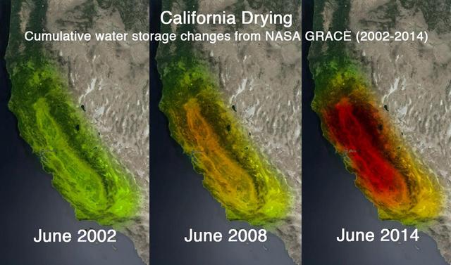
This trio of images depicts satellite observations of declining water storage in California as seen by NASA Gravity Recovery and Climate Experiment satellites in June 2002 left, June 2008 center and June 2014 right.
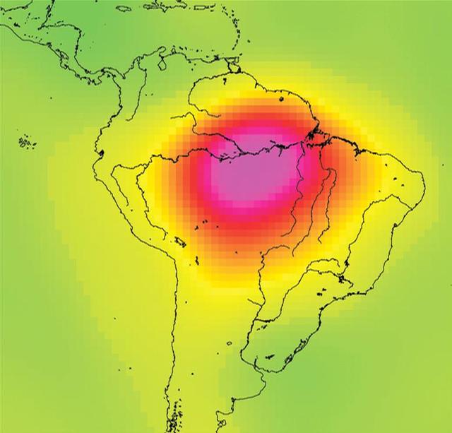
This image is from data taken by NASA Gravity Recovery and Climate Experiment showing the Amazon basin in South America. The amount of water stored in the Amazon basin varies from month to month. Animations are available at the Photojournal.
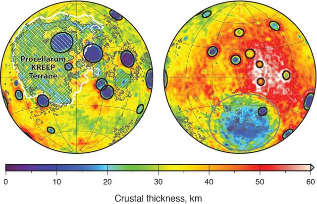
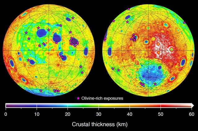
Global map of crustal thickness of the moon derived from gravity data obtained by NASA GRAIL spacecraft. The lunar near side is represented on the left hemisphere. The far side is represented in the right hemisphere.
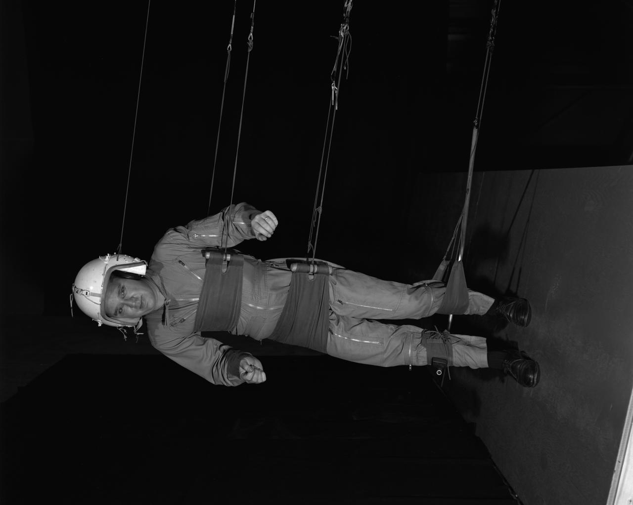
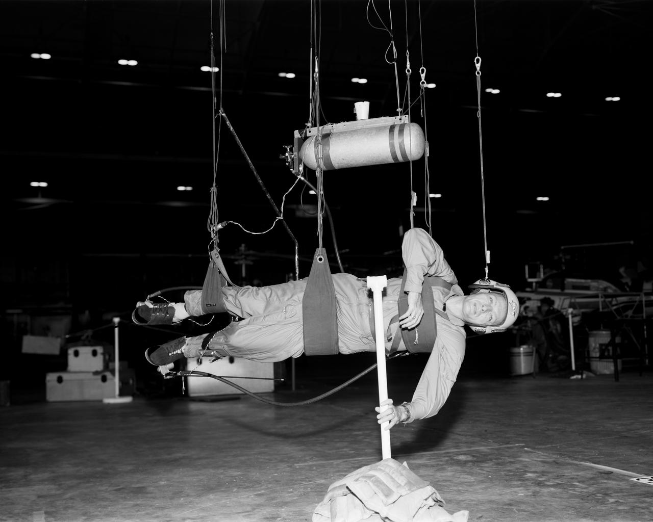
Walter Cronkite in the Reduced Gravity Simulator. Various views of Cronkite in the Lunar Landing Research Facility's Reduced Gravity Simulator which was used to train the astronauts for weightlessness. L68-8308 Caption: "During a 1968 visit to Langley, then CBS News Anchorman Walter Cronkite tries out the Reduced Gravity Simulator, a series of cable-supported slings designed to approximate the Moon's gravity, 1/6th that of Earth's." Photograph published in Winds of Change, 75th Anniversary NASA publication, p 91, by James Schultz.
Walter Cronkite in the Reduced Gravity Simulator. Various views of Cronkite in the Lunar Landing Research Facility's Reduced Gravity Simulator which was used to train the astronauts for weightlessness. L68-8308 Caption: "During a 1968 visit to Langley, then CBS News Anchorman Walter Cronkite tries out the Reduced Gravity Simulator, a series of cable-supported slings designed to approximate the Moon's gravity, 1/6th that of Earth's." Photograph published in Winds of Change, 75th Anniversary NASA publication, p 91, by James Schultz.
This set of images from NASA Dawn spacecraft shows topography of the southern hemisphere of the giant asteroid Vesta and a map of Vesta gravity variations that have been adjusted to account for Vesta shape.
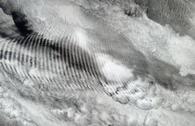
In this natural-color image from NASA Terra spacecraft, a fingerprint-like gravity wave feature occurs over a deck of marine stratocumulus clouds.
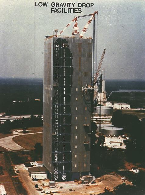
Low Gravity Drop Facility
NASA twin Gravity Recovery and Interior Laboratory GRAIL spacecraft are lowered onto the second stage of their Delta II launch vehicle. At top is the spacecraft adapter ring which holds the two lunar probes in their side-by-side launch configuration.
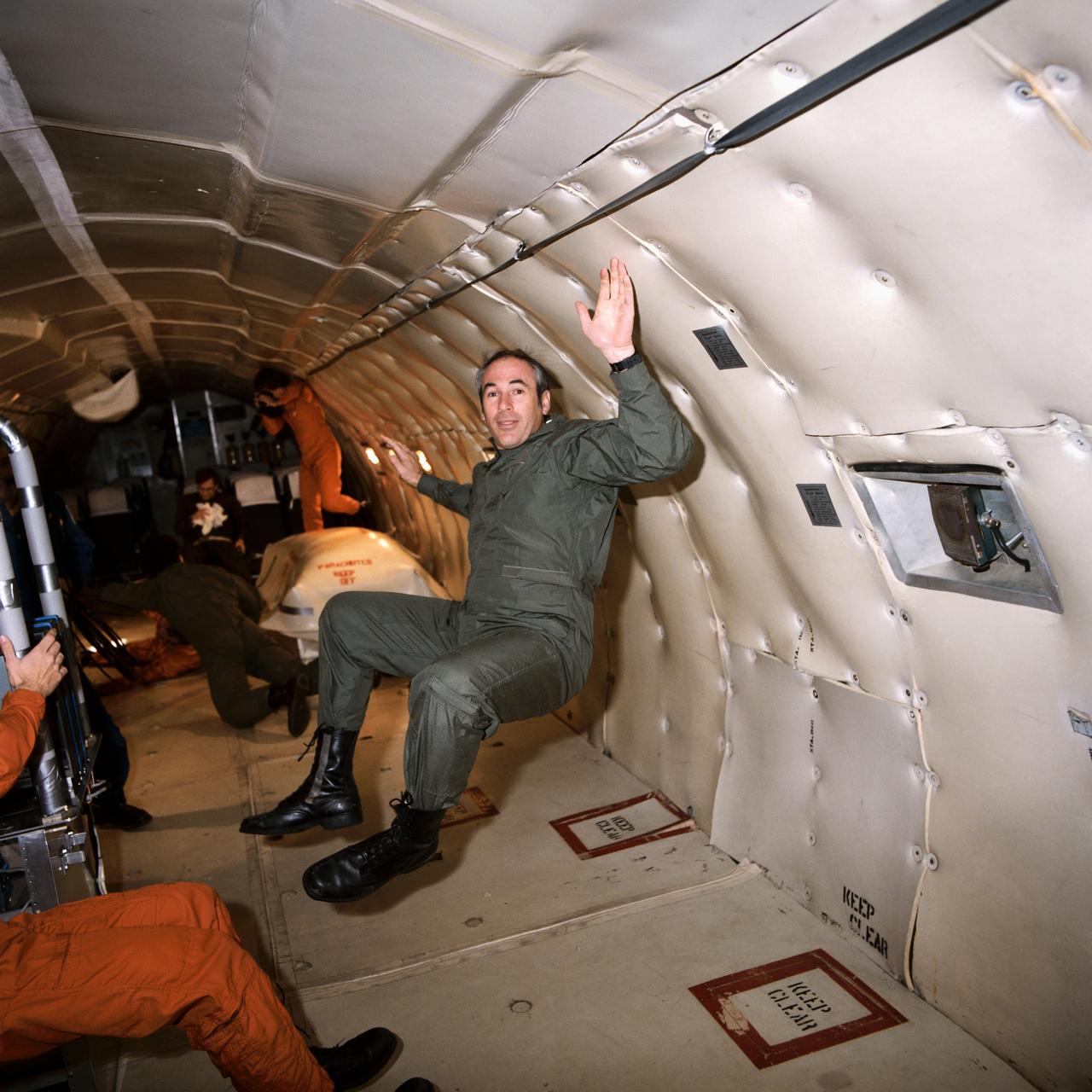
S85-26106 (25 Jan. 1985) --- Astronaut Gregory Jarvis gets a familiarization session in weightlessness aboard a KC-135 "zero gravity" aircraft. Jarvis was originally assigned as payload specialist to STS-51D but was reassigned to STS-51L. Photo credit: NASA

An experiment vehicle plunges into the deceleration pit at the end of a 5.18-second drop in the Zero-Gravity Research Facility at NASA's Glenn Research Center. The Zero-Gravity Research Facility was developed to support microgravity research and development programs that investigate various physical sciences, materials, fluid physics, and combustion and processing systems. Payloads up to 1 meter in diameter and 455 kg in weight can be accommodated. The facility has a 145-meter evacuated shaft to ensure a disturbance-free drop. This is No.1 of a sequence of 4 images. (Credit: NASA/Glenn Research Center)
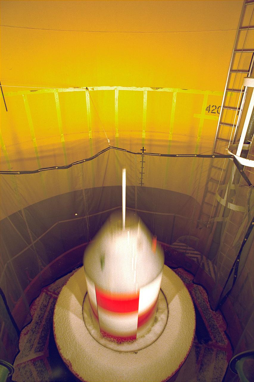
An experiment vehicle plunges into the deceleration pit at the end of a 5.18-second drop in the Zero-Gravity Research Facility at NASA's Glenn Research Center. The Zero-Gravity Research Facility was developed to support microgravity research and development programs that investigate various physical sciences, materials, fluid physcis, and combustion and processing systems. Payloads up to 1 meter in diameter and 455 kg in weight can be accommodated. The facility has a 145-meter evacuated shaft to ensure a disturbance-free drop. This is No. 2 of a sequence of 4 images. (Credit: NASA/Glenn Research Center)

An experiment vehicle plunges into the deceleration at the end of a 5.18-second drop in the Zero-Gravity Research Facility at NASA's Glenn Research Center. The Zero-Gravity Research Facility was developed to support microgravity research and development programs that investigate various physical sciences, materials, fluid physics, and combustion and processing systems. Payloads up to one-meter in diameter and 455 kg in weight can be accommodated. The facility has a 145-meter evacuated shaft to ensure a disturbance-free drop. This is No. 3 of a sequence of 4 images. (Credit: NASA/Glenn Research Center)

An experiment vehicle plunges into the deceleration pit at the end of a 5.18-second drop in the Zero-Gravity Research Facility at NASA's Glenn Research Center. The Zero-Gravity Research Facility was developed to support microgravity research and development programs that investigate various physical sciences, materials, fluid physics, and combustion and processing systems. Payloads up to one meter in diameter and 455 kg in weight can be accommodated. The facility has a 145-meter evacuated shaft to ensure a disturbance-free drop. This is No. 4 of a sequence of 4 images. (Credit: NASA/Glenn Research Center)
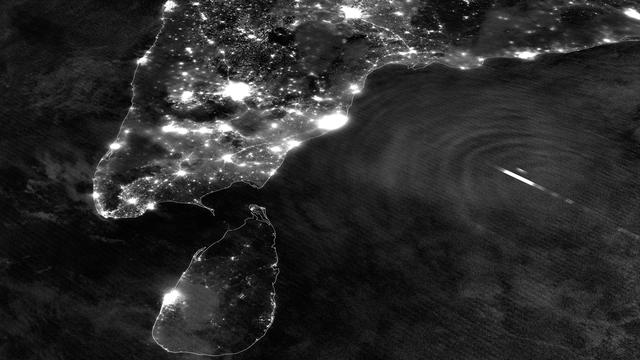
Tropical Cyclone Mahasen is moving north through the Indian Ocean along a track that places landfall along the Bangladesh coast on May 16th around 1200Z. On May 13, 2013 the Suomi NPP satellite caught an interesting glimpse of the storm as it moved off the eastern coast of India. The VIIRS Day-Night Band was able to resolve lightning flashes towards the center of the storm, along with mesopheric gravity waves emanating outwards like ripples in a pond. These gravity waves are of particular interest to air traffic controllers so assist in identifying areas of turbulence. Since the moon was in a new phase, the lights and other surface features of India and Sri Lanka are clearly visible, though the clouds of TC Mahasen are not - a tradeoff that occurs as the amount of moonlight cycles throughout the month. Credit: NASA/NOAA <b><a href="http://www.nasa.gov/audience/formedia/features/MP_Photo_Guidelines.html" rel="nofollow">NASA image use policy.</a></b> <b><a href="http://www.nasa.gov/centers/goddard/home/index.html" rel="nofollow">NASA Goddard Space Flight Center</a></b> enables NASA’s mission through four scientific endeavors: Earth Science, Heliophysics, Solar System Exploration, and Astrophysics. Goddard plays a leading role in NASA’s accomplishments by contributing compelling scientific knowledge to advance the Agency’s mission. <b>Follow us on <a href="http://twitter.com/NASA_GoddardPix" rel="nofollow">Twitter</a></b> <b>Like us on <a href="http://www.facebook.com/pages/Greenbelt-MD/NASA-Goddard/395013845897?ref=tsd" rel="nofollow">Facebook</a></b> <b>Find us on <a href="http://instagram.com/nasagoddard?vm=grid" rel="nofollow">Instagram</a></b>
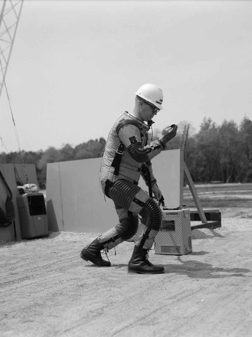
Special "space" suit for the Reduced Gravity Walking Simulator located at the Lunar Landing Facility. The purpose of this simulator was to study the subject while walking, jumping or running. Researchers conducted studies of various factors such as fatigue limit, energy expenditure, and speed of locomotion. A.W. Vigil described the purpose of the simulator in his paper "Discussion of Existing and Planned Simulators for Space Research," "When the astronauts land on the moon they will be in an unfamiliar environment involving, particularly, a gravitational field only one-sixth as strong as on earth. A novel method of simulating lunar gravity has been developed and is supported by a puppet-type suspension system at the end of a long pendulum. A floor is provided at the proper angle so that one-sixth of the subject's weight is supported by the floor with the remainder being supported by the suspension system. This simulator allows almost complete freedom in vertical translation and pitch and is considered to be a very realistic simulation of the lunar walking problem. For this problem this simulator suffers only slightly from the restrictions in lateral movement it puts on the test subject. This is not considered a strong disadvantage for ordinary walking problems since most of the motions do, in fact, occur in the vertical plane. However, this simulation technique would be severely restrictive if applied to the study of the extra-vehicular locomotion problem, for example, because in this situation complete six degrees of freedom are rather necessary. This technique, in effect, automatically introduces a two-axis attitude stabilization system into the problem. The technique could, however, be used in preliminary studies of extra-vehicular locomotion where, for example, it might be assumed that one axis of the attitude control system on the astronaut maneuvering unit may have failed." -- Published in James R. Hansen, Spaceflight Revolution: NASA Langley Research Center From Sputnik to Apollo, (Washington: NASA, 1995), p. 377; A.W. Vigil, "Discussion of Existing and Planned Simulators for Space Research," Paper presented at Conference on the Role of Simulation in Space Technology," Blacksburg, VA, August 17-21, 1964.

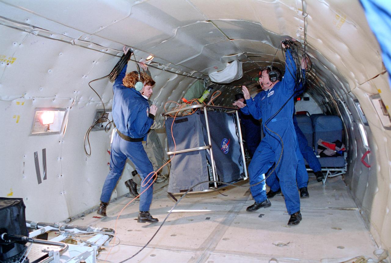
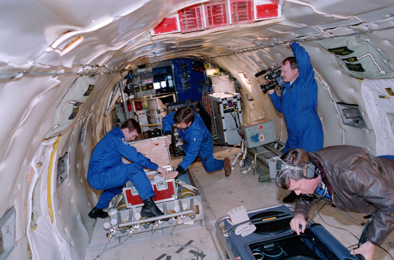
The Reduced-Gravity Program provides the unique weightless or zero-g environment of space flight for testing and training of human and hardware reactions. The reduced-gravity environment is obtained with a specially modified KC-135A turbojet transport which flies parabolic arcs to produce weightless periods of 20 to 25 seconds. KC-135A cargo bay test area is approximately 60 feet long, 10 feet wide, and 7 feet high. The image shows KC-135A in flight.
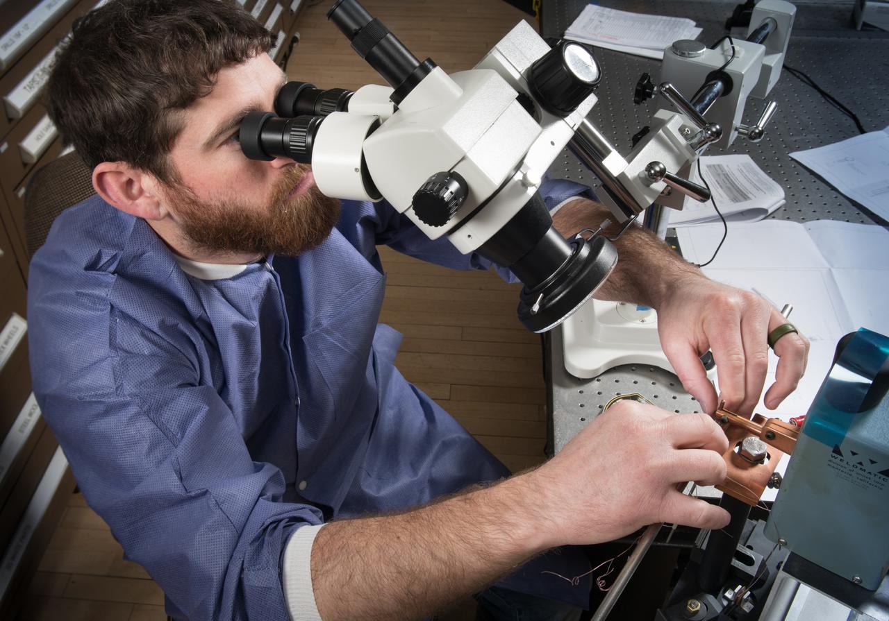
A technician in the Instrumentation Shop during the buildup of Flow Boiling Condensation Experiment, FBCE Micro Gravity Payload, Condensation Module – Heat Transfer, CM-HT, Test Section Hardware Fabrication
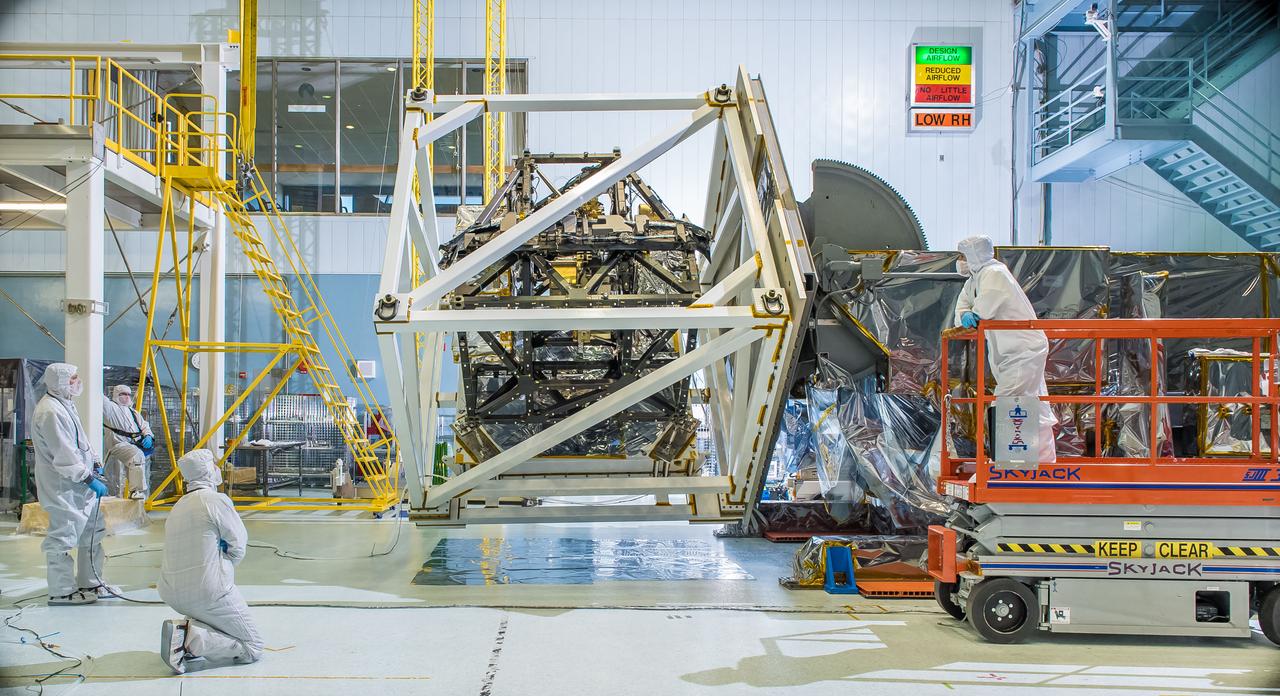
The James Webb Space Telescope's ISIM structure recently endured a "gravity sag test" as it was rotated in what looked like giant cube in a NASA clean room. The Integrated Science Instrument Module (ISIM) that will fly on the Webb telescope was rotated upside down inside a cube-like structure in the cleanroom at NASA's Goddard Space Flight Center in Greenbelt, Maryland. The purpose of "cubing" the ISIM was to test it for "gravity sag," which is to see how much the structure changes under its own weight due to gravity. The Integrated Science Instrument Module (ISIM) is one of three major elements that comprise the Webb Observatory flight system. The others are the Optical Telescope Element (OTE) and the Spacecraft Element (Spacecraft Bus and Sunshield). Read more: <a href="http://1.usa.gov/1ze7u2l" rel="nofollow">1.usa.gov/1ze7u2l</a> Credit: NASA/Goddard/Chris Gunn <b><a href="http://www.nasa.gov/audience/formedia/features/MP_Photo_Guidelines.html" rel="nofollow">NASA image use policy.</a></b> <b><a href="http://www.nasa.gov/centers/goddard/home/index.html" rel="nofollow">NASA Goddard Space Flight Center</a></b> enables NASA’s mission through four scientific endeavors: Earth Science, Heliophysics, Solar System Exploration, and Astrophysics. Goddard plays a leading role in NASA’s accomplishments by contributing compelling scientific knowledge to advance the Agency’s mission. <b>Follow us on <a href="http://twitter.com/NASAGoddardPix" rel="nofollow">Twitter</a></b> <b>Like us on <a href="http://www.facebook.com/pages/Greenbelt-MD/NASA-Goddard/395013845897?ref=tsd" rel="nofollow">Facebook</a></b> <b>Find us on <a href="http://instagram.com/nasagoddard?vm=grid" rel="nofollow">Instagram</a></b>
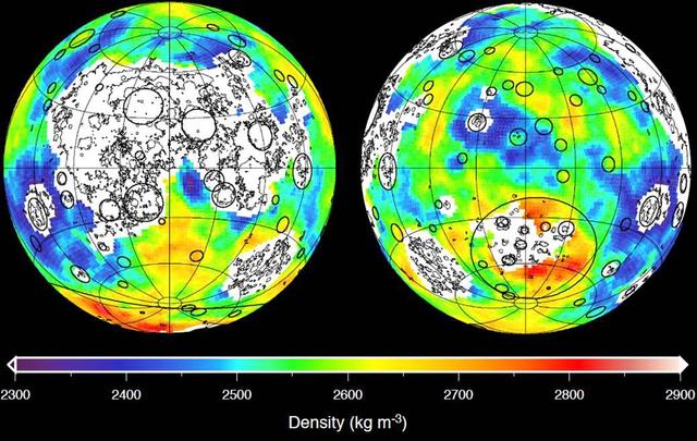
This graphic depicting the bulk density of the lunar highlands on the near and far sides of the moon was generated using gravity data from NASA GRAIL mission and topography data from NASA Lunar Reconnaissance Orbiter.
This image shows the final flight path for NASA twin Gravity Recovery and Interior Laboratory GRAIL mission spacecraft, which will impact the moon on Dec. 17, 2012, around 2:28 p.m. PST.

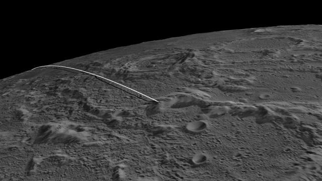
These side-by-side, 3-D comparisons depict the unnamed lunar mountain targeted by the NASA Gravity Recovery and Interior Laboratory GRAIL mission for controlled impact of the Ebb and Flow spacecraft.
This graphic depicting the bulk density of the lunar highlands on the near and far sides of the moon was generated using gravity data from NASA GRAIL mission and topography data from NASA Lunar Reconnaissance Orbiter.
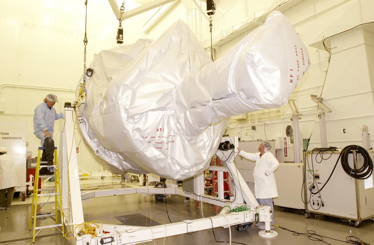
The Gravity Probe B experiment rests on an assembly and test stand in the spacecraft processing facility on North Vandenberg Air Force Base. Gravity Probe B will launch a payload of four gyroscopes into low-Earth polar orbit to test two extraordinary predictions of Albert Einstein’s general theory of relativity: the geodetic effect (how space and time are warped by the presence of the Earth) and frame dragging (how Earth’s rotation drags space and time around with it). Once in orbit, for 18 months each gyroscope’s spin axis will be monitored as it travels through local spacetime, observing and measuring these effects. The experiment was developed by Stanford University, Lockheed Martin and NASA’s Marshall Space Flight Center.
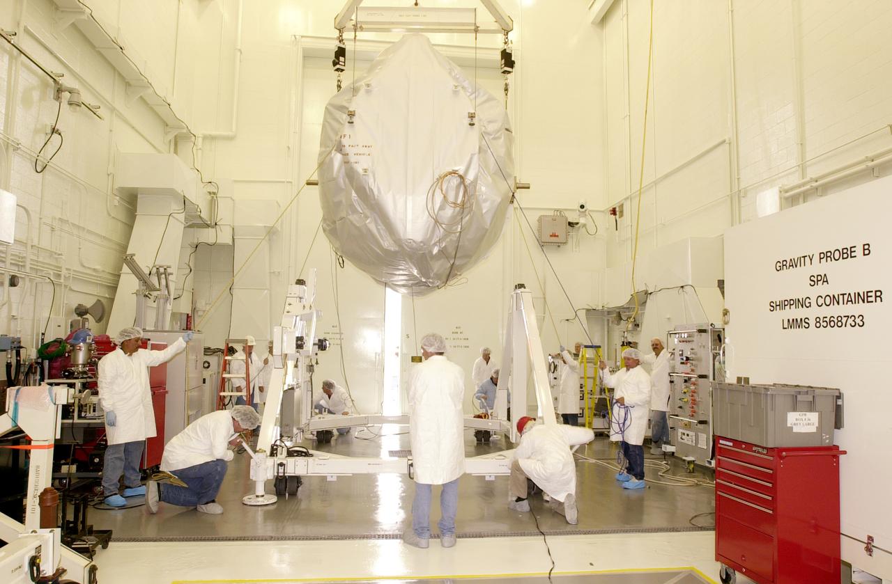
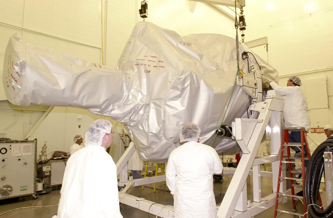
The Gravity Probe B experiment is lifted from its transporter in the spacecraft processing facility on North Vandenberg Air Force Base. Gravity Probe B will launch a payload of four gyroscopes into low-Earth polar orbit to test two extraordinary predictions of Albert Einstein’s general theory of relativity: the geodetic effect (how space and time are warped by the presence of the Earth) and frame dragging (how Earth’s rotation drags space and time around with it). Once in orbit, for 18 months each gyroscope’s spin axis will be monitored as it travels through local spacetime, observing and measuring these effects. The experiment was developed by Stanford University, Lockheed Martin and NASA’s Marshall Space Flight Center.
The Gravity Probe B experiment is lowered onto an assembly and test stand in the spacecraft processing facility on North Vandenberg Air Force Base. Gravity Probe B will launch a payload of four gyroscopes into low-Earth polar orbit to test two extraordinary predictions of Albert Einstein’s general theory of relativity: the geodetic effect (how space and time are warped by the presence of the Earth) and frame dragging (how Earth’s rotation drags space and time around with it). Once in orbit, for 18 months each gyroscope’s spin axis will be monitored as it travels through local spacetime, observing and measuring these effects. The experiment was developed by Stanford University, Lockheed Martin and NASA’s Marshall Space Flight Center.
The Gravity Probe B experiment enters the spacecraft processing facility on North Vandenberg Air Force Base. Gravity Probe B will launch a payload of four gyroscopes into low-Earth polar orbit to test two extraordinary predictions of Albert Einstein’s general theory of relativity: the geodetic effect (how space and time are warped by the presence of the Earth) and frame dragging (how Earth’s rotation drags space and time around with it). Once in orbit, for 18 months each gyroscope’s spin axis will be monitored as it travels through local spacetime, observing and measuring these effects. The experiment was developed by Stanford University, Lockheed Martin and NASA’s Marshall Space Flight Center.
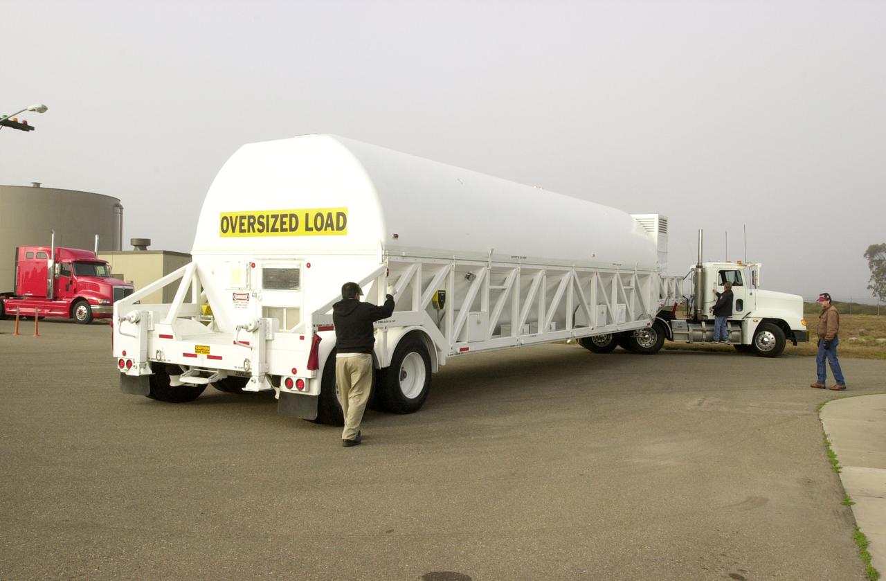
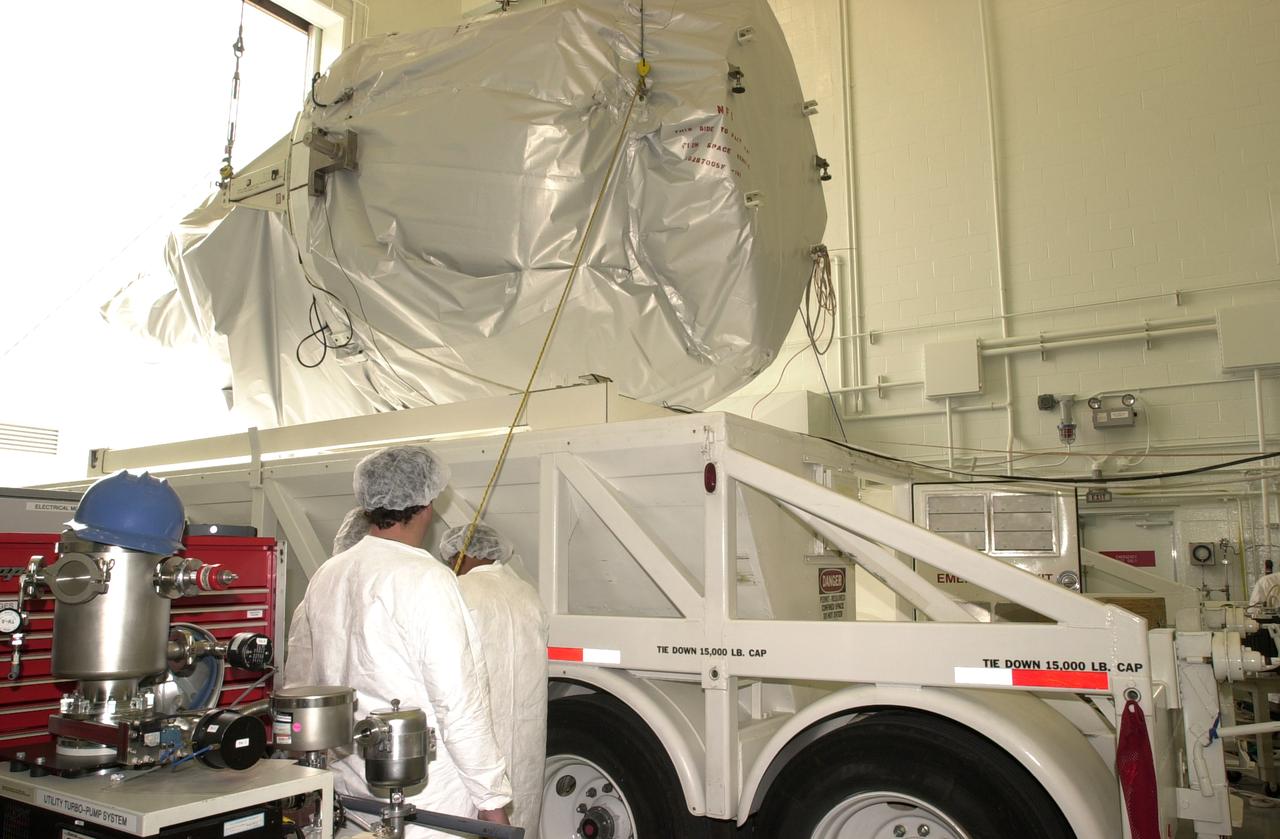
Enclosed in a canister, the Gravity Probe B (GP-B) spacecraft arrives on Vandenberg Air Force Base, headed for the spacecraft processing facility. Gravity Probe B will launch a payload of four gyroscopes into low-Earth polar orbit to test two extraordinary predictions of Albert Einstein’s general theory of relativity: the geodetic effect (how space and time are warped by the presence of the Earth) and frame dragging (how Earth’s rotation drags space and time around with it). Once in orbit, for 18 months each gyroscope’s spin axis will be monitored as it travels through local spacetime, observing and measuring these effects. The experiment was developed by Stanford University, Lockheed Martin and NASA’s Marshall Space Flight Center.
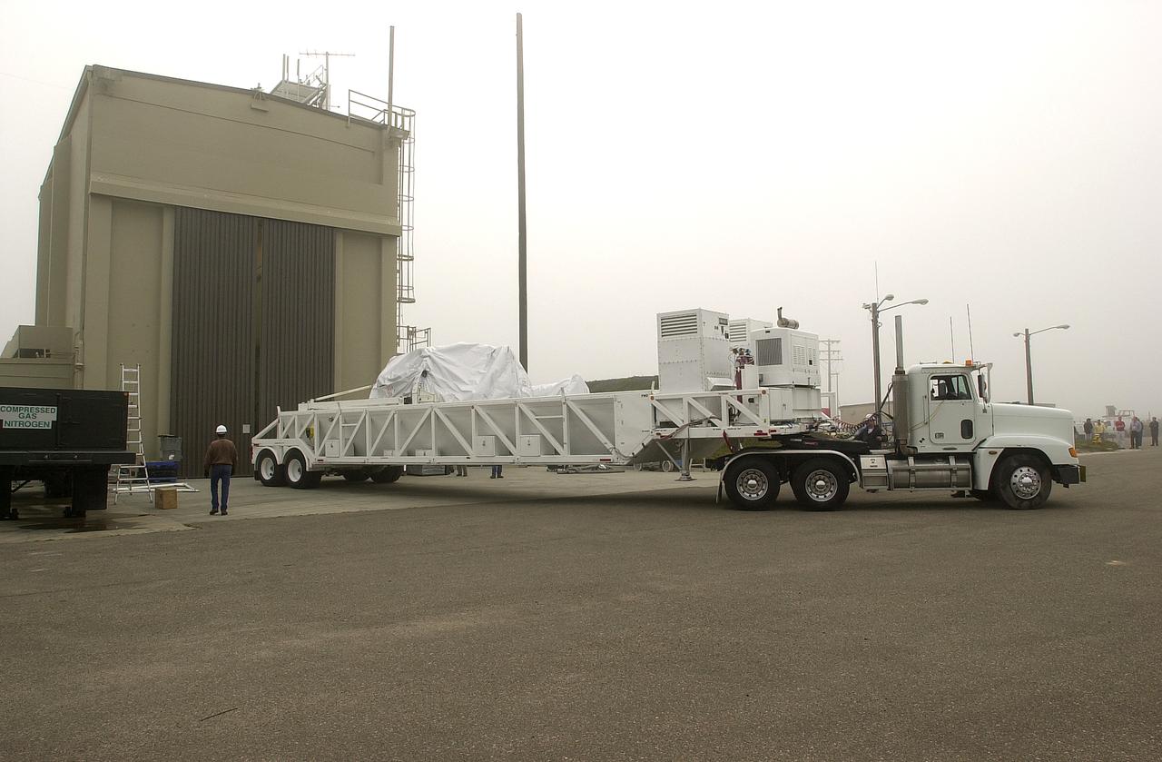
A transporter carrying the Gravity Probe B experiment backs into the spacecraft processing facility on North Vandenberg Air Force Base. Gravity Probe B will launch a payload of four gyroscopes into low-Earth polar orbit to test two extraordinary predictions of Albert Einstein’s general theory of relativity: the geodetic effect (how space and time are warped by the presence of the Earth) and frame dragging (how Earth’s rotation drags space and time around with it). Once in orbit, for 18 months each gyroscope’s spin axis will be monitored as it travels through local spacetime, observing and measuring these effects. The experiment was developed by Stanford University, Lockheed Martin and NASA’s Marshall Space Flight Center.
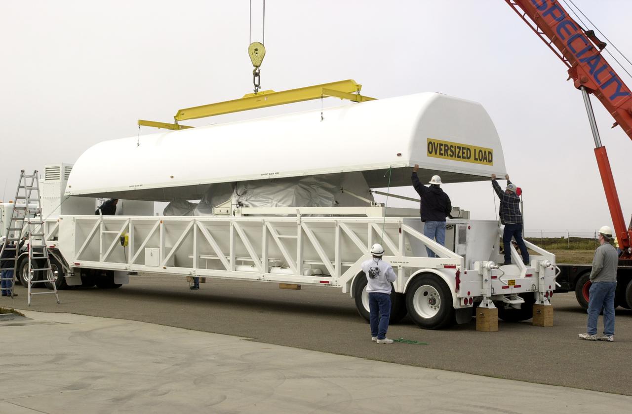
At Vandenberg AFB, the canister enclosing the Gravity Probe B (GP-B) spacecraft is removed from the transporter. Gravity Probe B will launch a payload of four gyroscopes into low-Earth polar orbit to test two extraordinary predictions of Albert Einstein’s general theory of relativity: the geodetic effect (how space and time are warped by the presence of the Earth) and frame dragging (how Earth’s rotation drags space and time around with it). Once in orbit, for 18 months each gyroscope’s spin axis will be monitored as it travels through local spacetime, observing and measuring these effects. The experiment was developed by Stanford University, Lockheed Martin and NASA’s Marshall Space Flight Center.
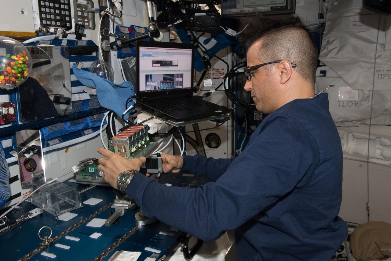
iss054e052250 (Feb. 20, 2018) --- NASA astronaut Joe Acaba removes Seed Cassettes for the Plant Gravity Perception experiment, which tests the gravity sensing ability of plants in microgravity.
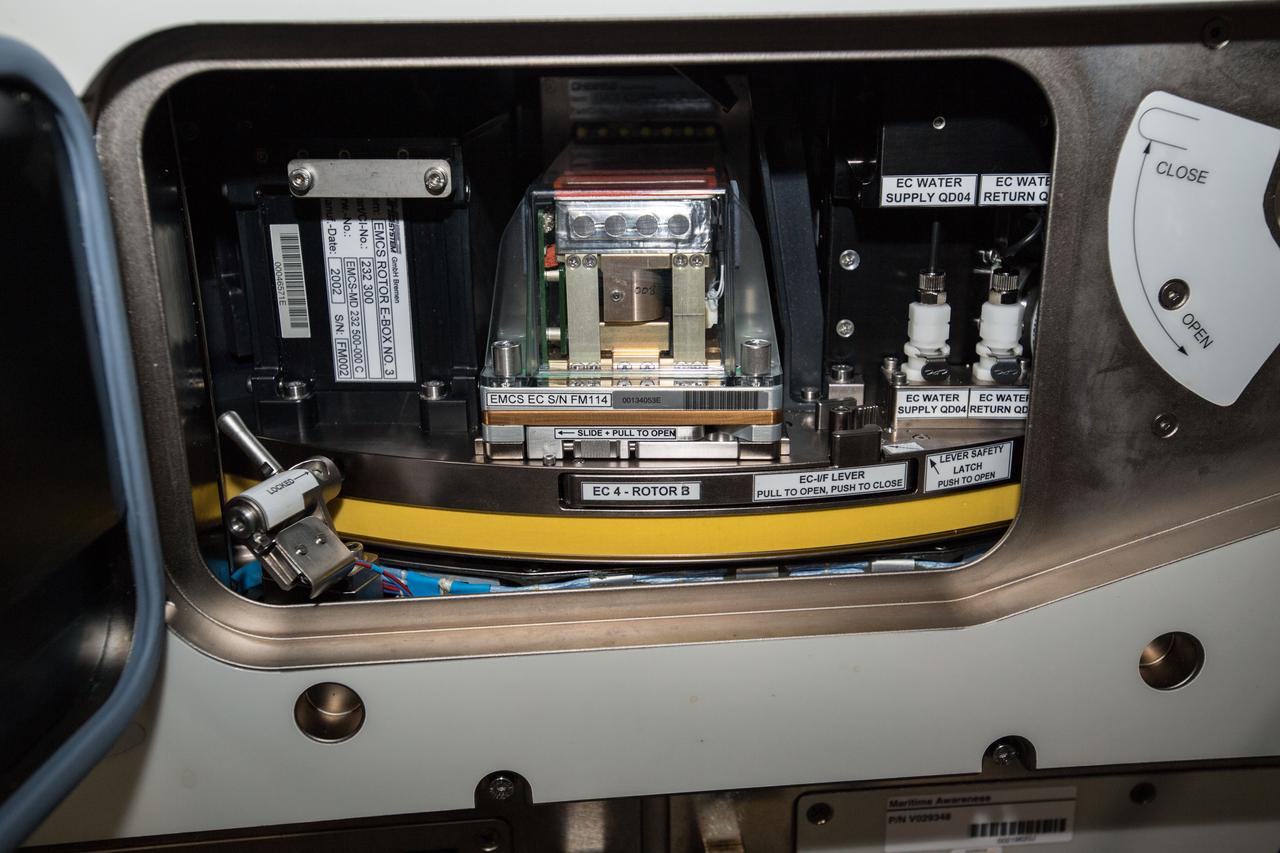
iss054e037079 (Feb. 8, 2018) --- Plant Gravity Perception experiment in a centrifuge on a European Modular Cultivation System (EMCS) Experiment Container (EC) to test the gravity-sensing ability of plants in microgravity.
Astronaut Walt Cunningham on the Reduced Gravity Walking Simulator located at the Lunar Landing Facility. The purpose of this simulator was to study the subject while walking, jumping or running. Researchers conducted studies of various factors such as fatigue limit, energy expenditure, and speed of locomotion. A.W. Vigil described the purpose of the simulator in his paper "Discussion of Existing and Planned Simulators for Space Research," "When the astronauts land on the moon they will be in an unfamiliar environment involving, particularly, a gravitational field only one-sixth as strong as on earth. A novel method of simulating lunar gravity has been developed and is supported by a puppet-type suspension system at the end of a long pendulum. A floor is provided at the proper angle so that one-sixth of the subject's weight is supported by the floor with the remainder being supported by the suspension system. This simulator allows almost complete freedom in vertical translation and pitch and is considered to be a very realistic simulation of the lunar walking problem. For this problem this simulator suffers only slightly from the restrictions in lateral movement it puts on the test subject. This is not considered a strong disadvantage for ordinary walking problems since most of the motions do, in fact, occur in the vertical plane. However, this simulation technique would be severely restrictive if applied to the study of the extra-vehicular locomotion problem, for example, because in this situation complete six degrees of freedom are rather necessary. This technique, in effect, automatically introduces a two-axis attitude stabilization system into the problem. The technique could, however, be used in preliminary studies of extra-vehicular locomotion where, for example, it might be assumed that one axis of the attitude control system on the astronaut maneuvering unit may have failed." -- Published in James R. Hansen, Spaceflight Revolution: NASA Langley Research Center From Sputnik to Apollo, (Washington: NASA, 1995), p. 377; A.W. Vigil, "Discussion of Existing and Planned Simulators for Space Research," Paper presented at Conference on the Role of Simulation in Space Technology," Blacksburg, VA, August 17-21, 1964.
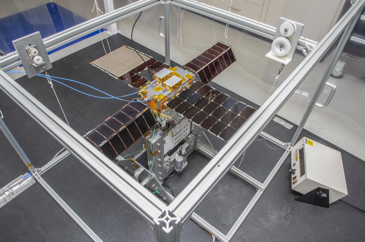
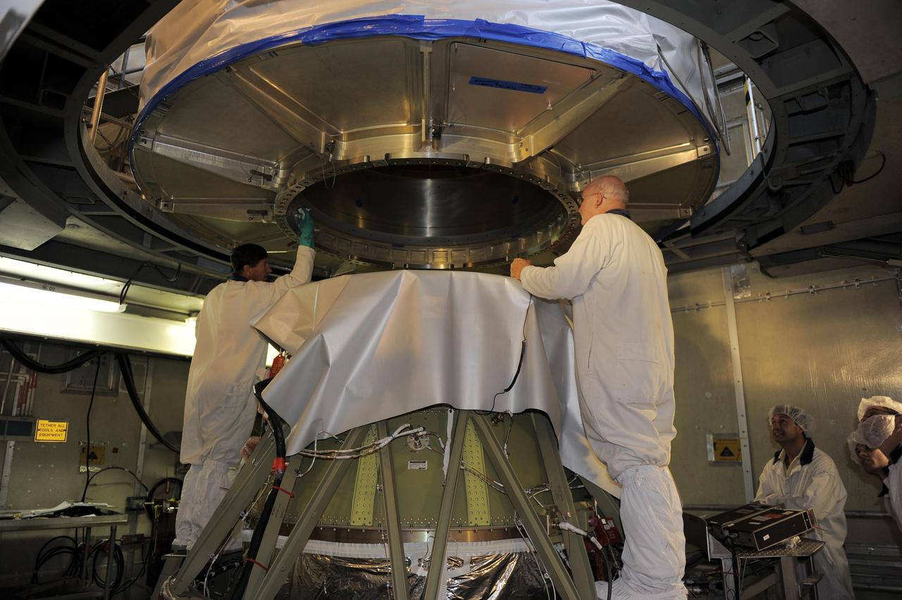
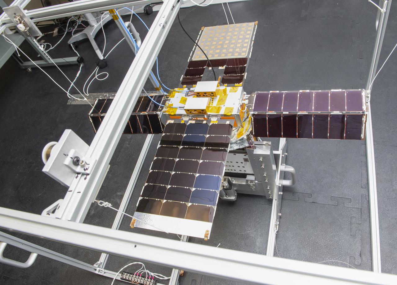
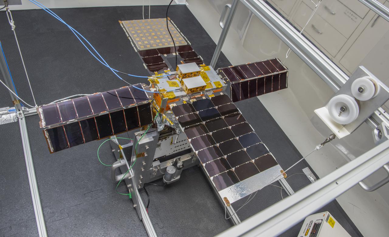
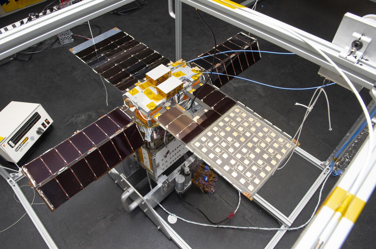
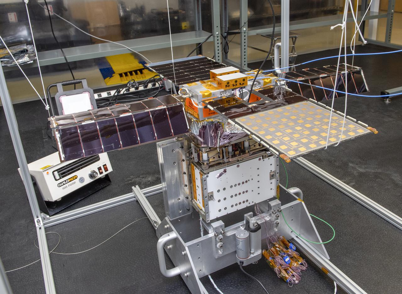
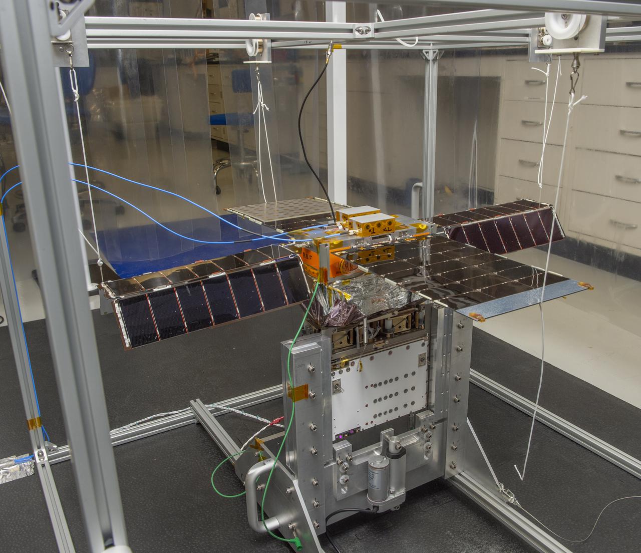
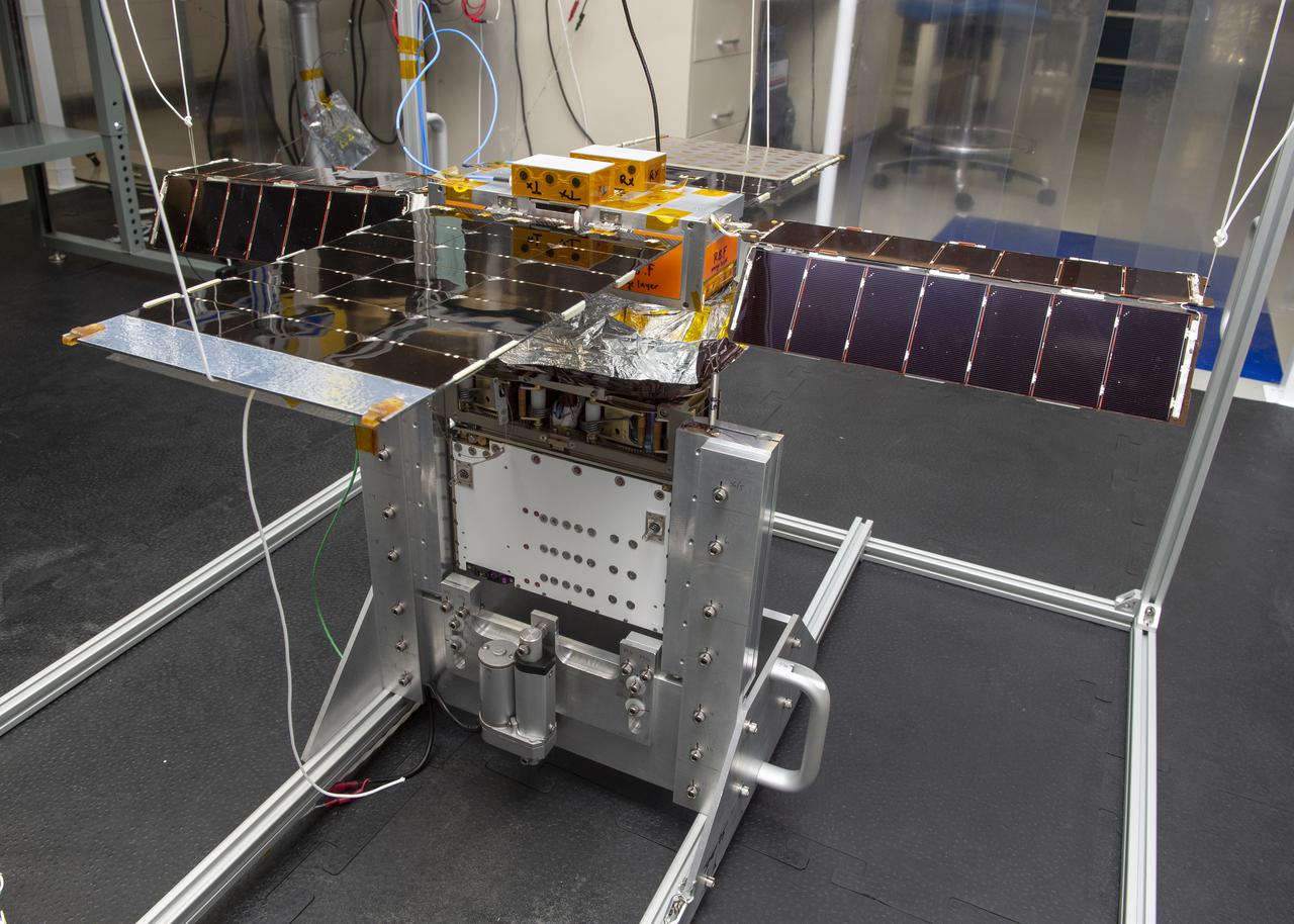
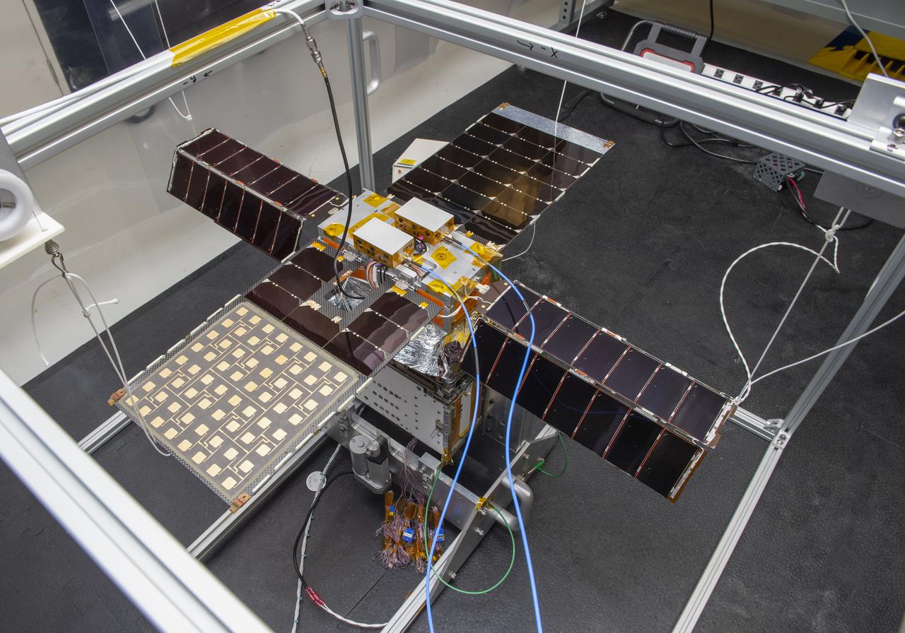
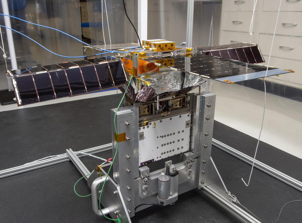
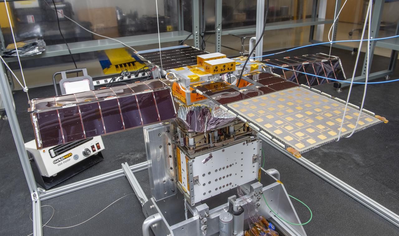
Spacecraft in Gravity Off-load Fixture (GOLF), System Test configuration - Arisa Waddle – Test Engineer, Rick Wilson – Lead Test Engineer
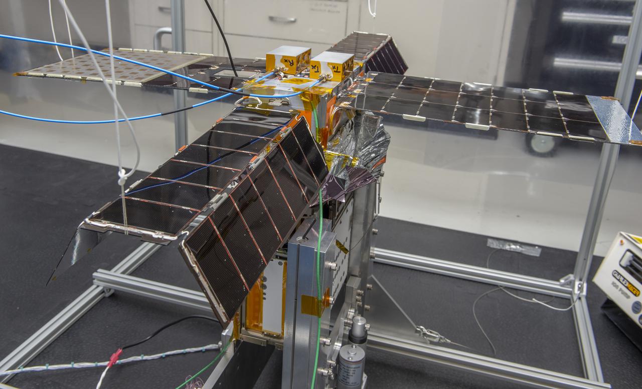
Spacecraft in Gravity Off-load Fixture (GOLF), System Test configuration - Arisa Waddle – Test Engineer, Rick Wilson – Lead Test Engineer

Spacecraft in Gravity Off-load Fixture (GOLF), System Test configuration - Arisa Waddle – Test Engineer, Rick Wilson – Lead Test Engineer
Spacecraft in Gravity Off-load Fixture (GOLF), System Test configuration - Arisa Waddle – Test Engineer, Rick Wilson – Lead Test Engineer
Spacecraft in Gravity Off-load Fixture (GOLF), System Test configuration - Arisa Waddle – Test Engineer, Rick Wilson – Lead Test Engineer
Spacecraft in Gravity Off-load Fixture (GOLF), System Test configuration - Arisa Waddle – Test Engineer, Rick Wilson – Lead Test Engineer
Spacecraft in Gravity Off-load Fixture (GOLF), System Test configuration - Arisa Waddle – Test Engineer, Rick Wilson – Lead Test Engineer
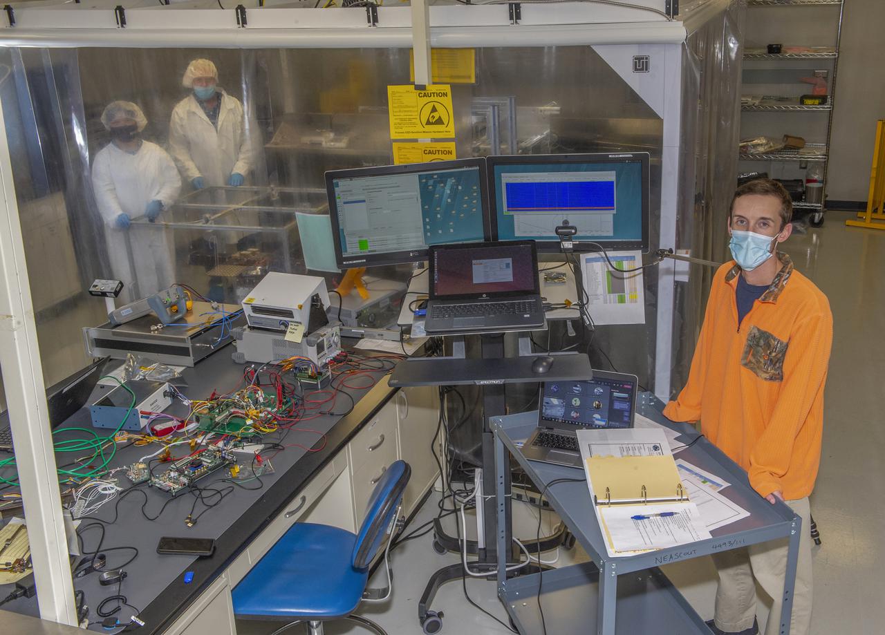
Spacecraft in Gravity Off-load Fixture (GOLF), System Test configuration - Arisa Waddle – Test Engineer, Rick Wilson – Lead Test Engineer
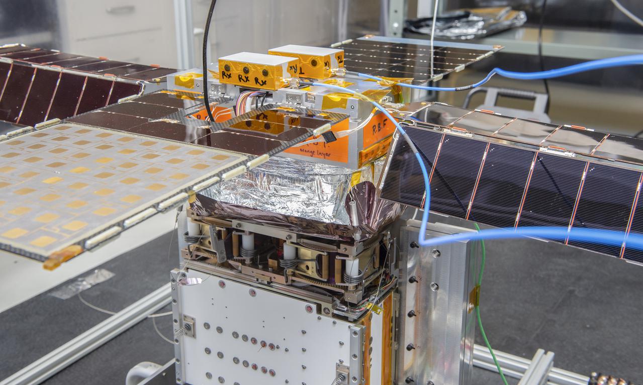
Spacecraft in Gravity Off-load Fixture (GOLF), System Test configuration - Arisa Waddle – Test Engineer, Rick Wilson – Lead Test Engineer
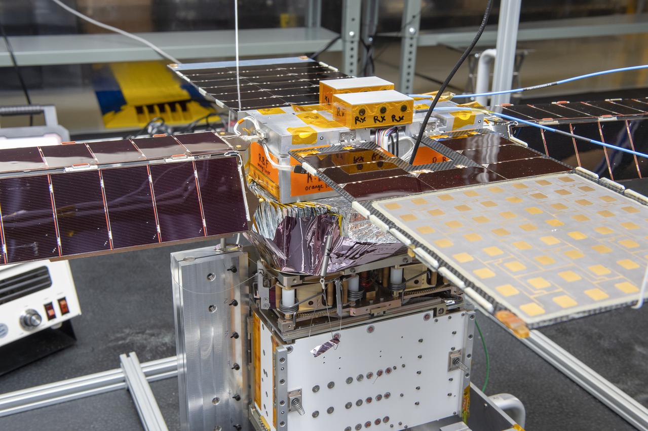
Spacecraft in Gravity Off-load Fixture (GOLF), System Test configuration - Arisa Waddle – Test Engineer, Rick Wilson – Lead Test Engineer
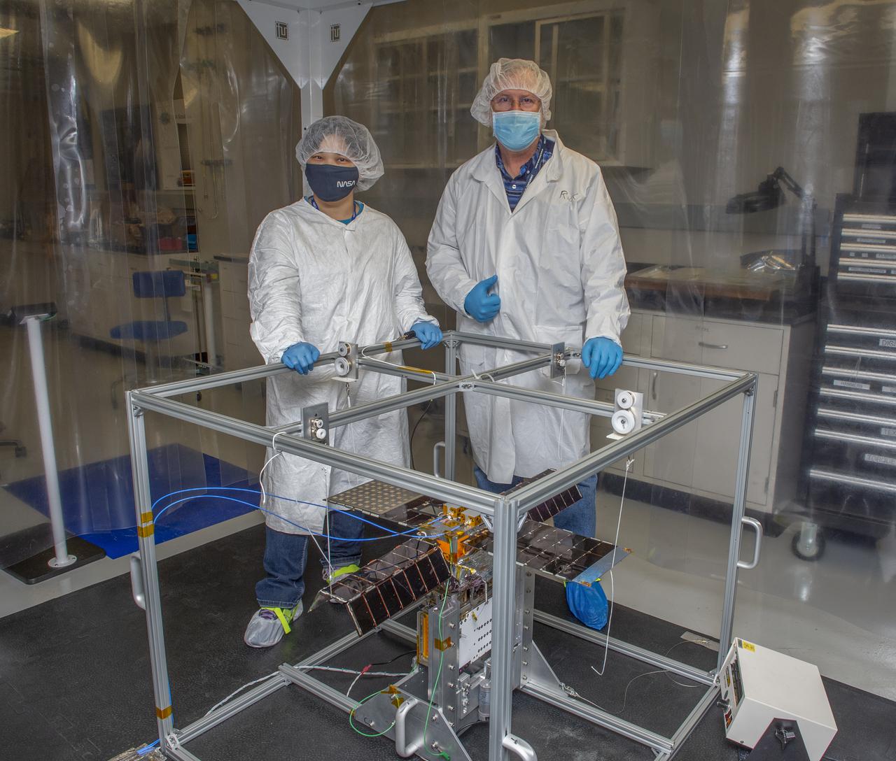
Spacecraft in Gravity Off-load Fixture (GOLF), System Test configuration - Arisa Waddle – Test Engineer, Rick Wilson – Lead Test Engineer

Spacecraft in Gravity Off-load Fixture (GOLF), System Test configuration - Arisa Waddle – Test Engineer, Rick Wilson – Lead Test Engineer
Spacecraft in Gravity Off-load Fixture (GOLF), System Test configuration - Arisa Waddle – Test Engineer, Rick Wilson – Lead Test Engineer
Spacecraft in Gravity Off-load Fixture (GOLF), System Test configuration - Arisa Waddle – Test Engineer, Rick Wilson – Lead Test Engineer
Spacecraft in Gravity Off-load Fixture (GOLF), System Test configuration - Arisa Waddle – Test Engineer, Rick Wilson – Lead Test Engineer
Spacecraft in Gravity Off-load Fixture (GOLF), System Test configuration - Arisa Waddle – Test Engineer, Rick Wilson – Lead Test Engineer
Spacecraft in Gravity Off-load Fixture (GOLF), System Test configuration - Arisa Waddle – Test Engineer, Rick Wilson – Lead Test Engineer
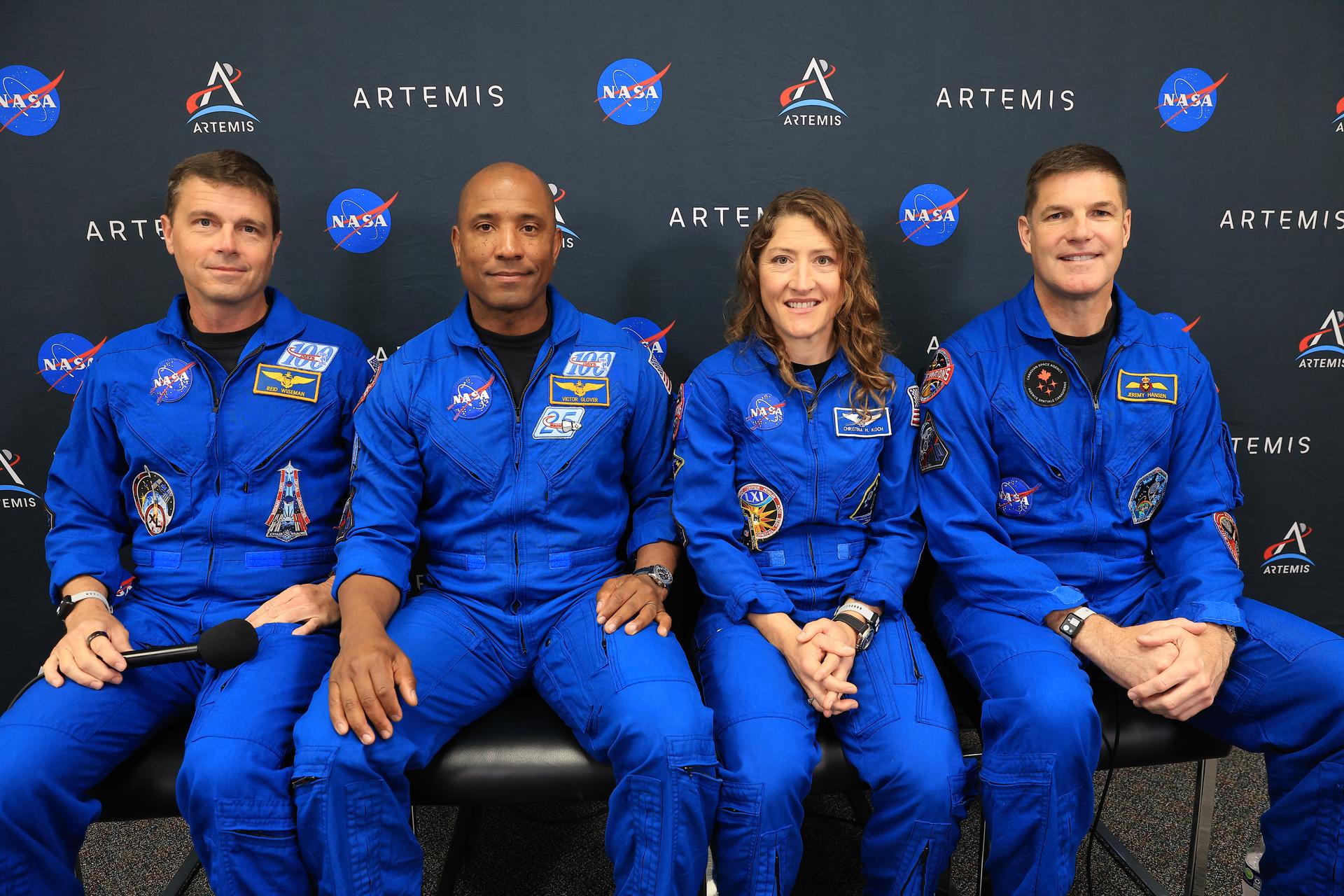
Artemis II Crew Q and A and Zero Gravity Indicator