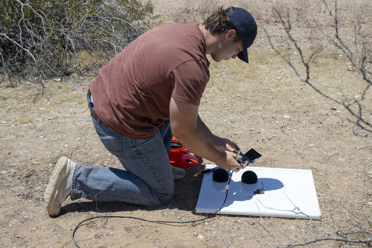
A NASA intern sets up ground recording system (GRS) units in California’s Mojave Desert during a Phase 2 rehearsal of the agency’s Quesst mission. The GRS units were placed across miles of desert terrain to capture the acoustic signature of supersonic aircraft during rehearsal flights and in preparation for the start of the actual tests.
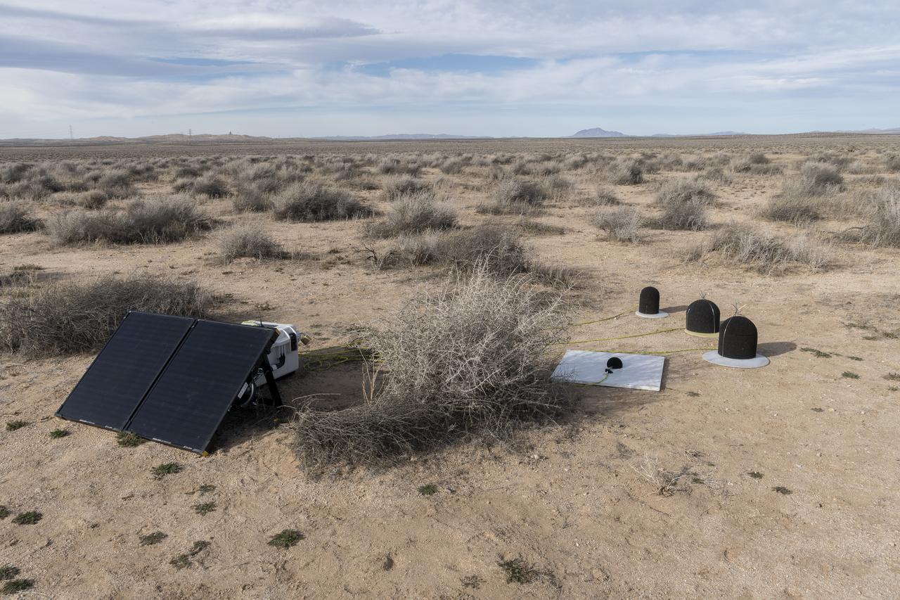
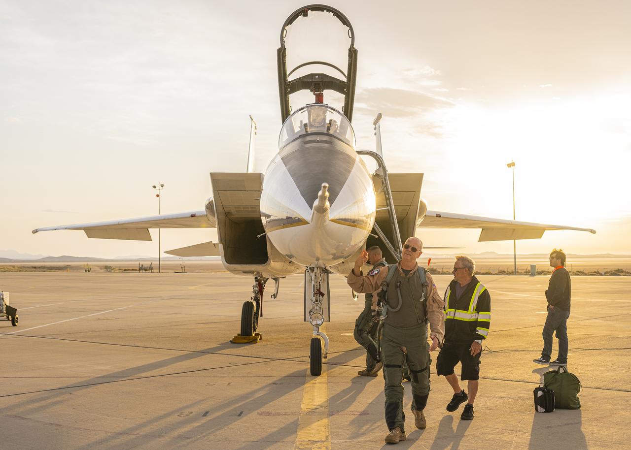
The Quesst mission recently completed testing of operations and equipment to be used in recording the sonic thumps of the X-59. Shown is one of 10 ground recording stations set up along a 30-mile stretch of desert to record sonic booms during the third phase of the of CarpetDIEM, Carpet Determination in Entirety Measurements flights. An F-15 and an F-18 from NASA’s Armstrong Flight Research Center created sonic booms, both loud and soft, to verify the operations of ground recording systems.
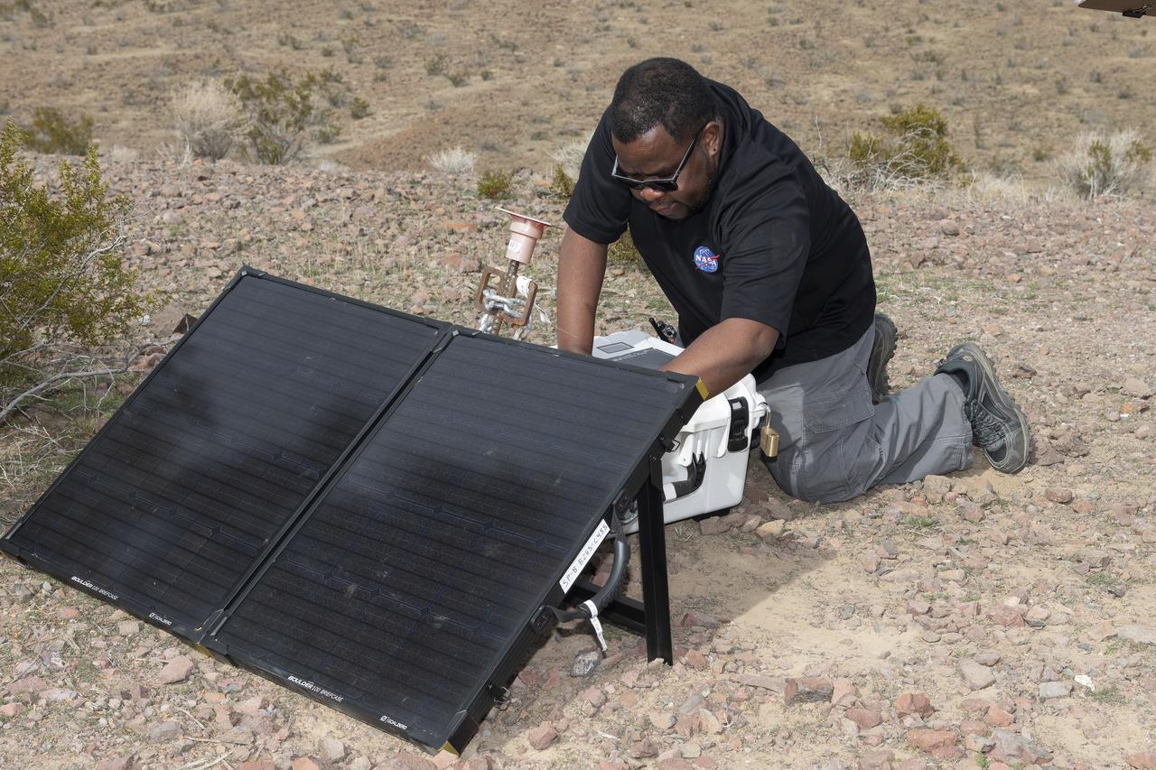
Aerospace engineer Larry Cliatt, Quesst Phase 2 Sub-Project Manager abd technical lead for the acoustic validation phase of the Quesst mission, sets up a ground recording system in the California desert. The Quesst mission recently completed testing of operations and equipment to be used in recording the sonic thumps of the X-59. The testing was the third phase of Carpet Determination in Entirety Measurements flights, called CarpetDIEM for short. An F-15 and an F-18 from NASA’s Armstrong Flight Research Center created sonic booms, both loud and soft, to verify the operations of ground recording systems spread out across 30 miles of open desert.
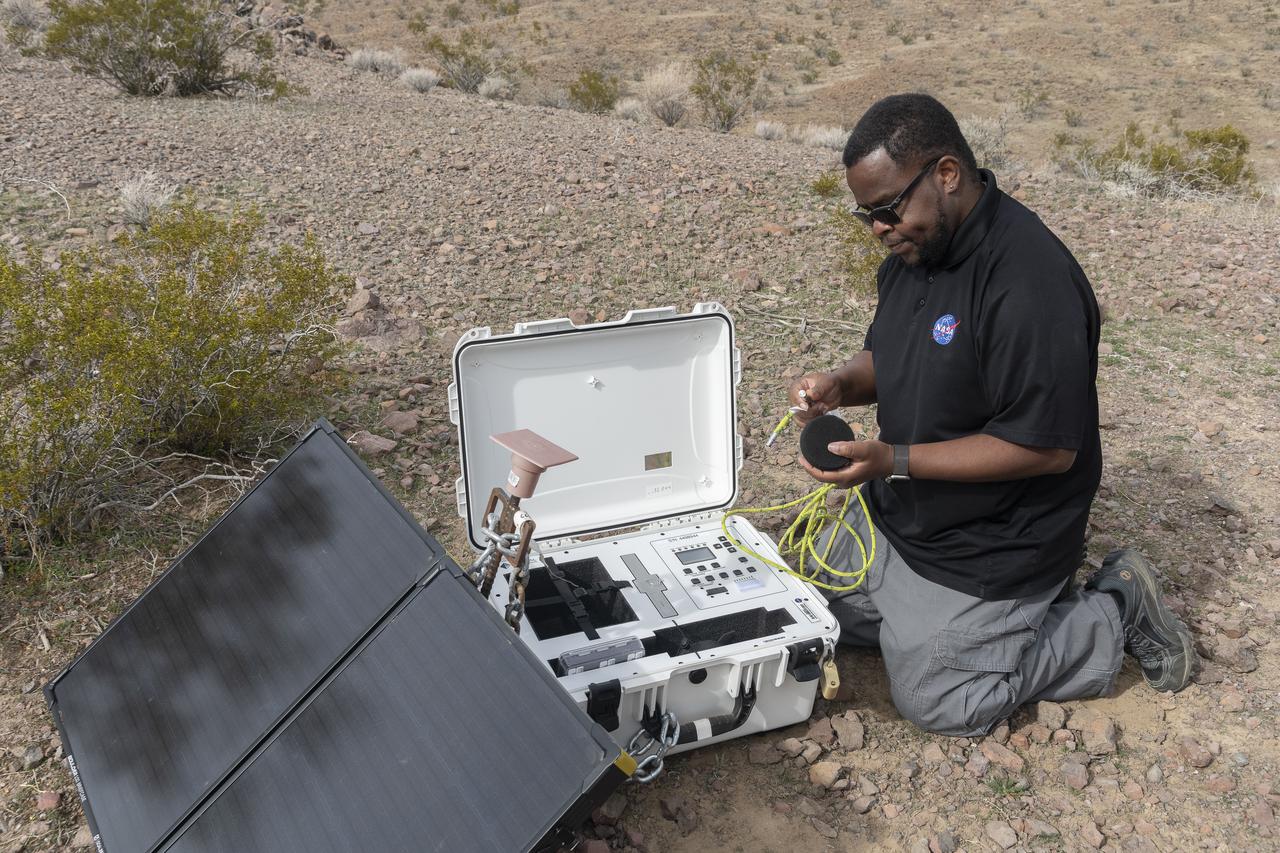
Aerospace engineer Larry Cliatt, Quesst Phase 2 Sub-Project Manager and technical lead for the acoustic validation phase of the Quesst mission, sets up a ground recording system in the California desert. The Quesst mission recently completed testing of operations and equipment to be used in recording the sonic thumps of the X-59. The testing was the third phase of Carpet Determination in Entirety Measurements flights, called CarpetDIEM for short. An F-15 and an F-18 from NASA’s Armstrong Flight Research Center created sonic booms, both loud and soft, to verify the operations of ground recording systems spread out across 30 miles of open desert.
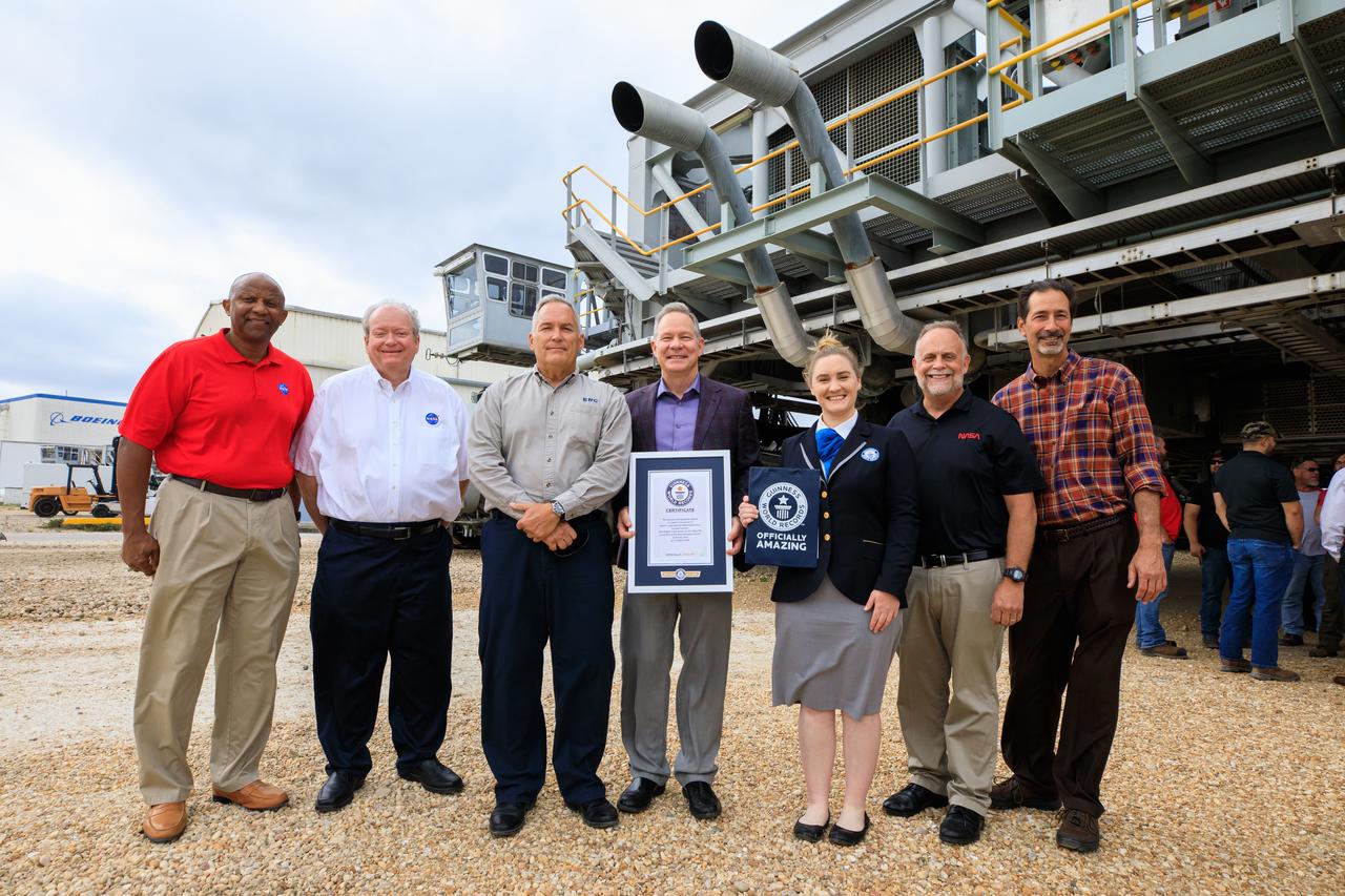
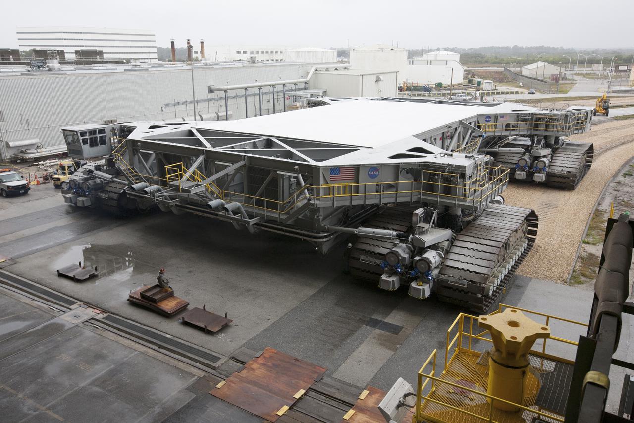
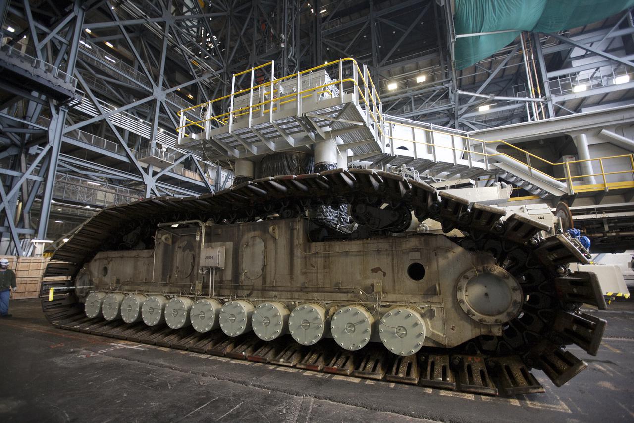
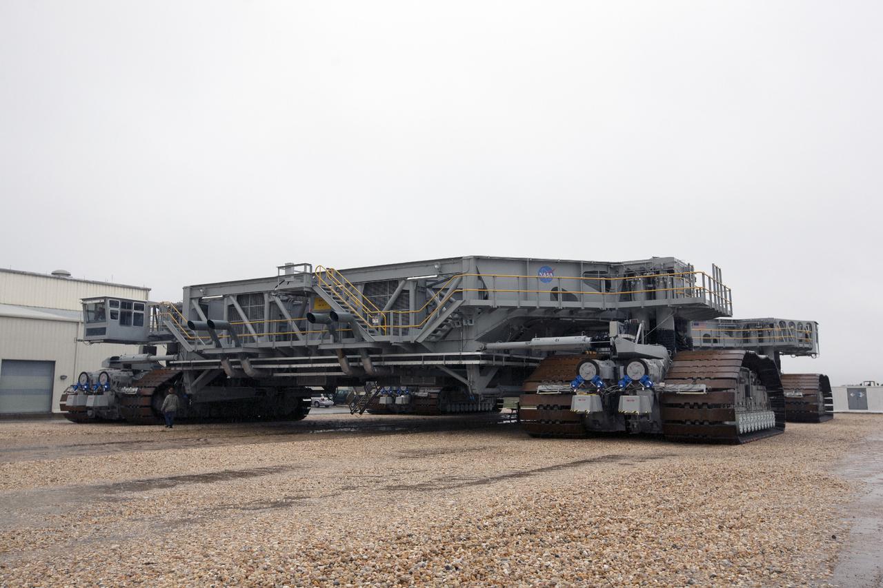
Guinness World Records officially designated NASA’s Crawler Transporter 2 as the heaviest self-powered vehicle, weighing approximately 6.65 million pounds. During a March 29, 2023, ceremony at the agency's Kennedy Space Center in Florida, Guinness World Records presented a certificate to teams with the Exploration Ground Systems Program and Kennedy leadership. Pictured, from left, are: Kelvin Manning, Kennedy deputy director; Burt Summerfield, Kennedy associate director, management; Brett Raulerson, Jacobs TOSC Crawlers, Transporters and Structures group manager; Gary Casteel, Jacobs director, Ground Systems Support; Hannah Ortman, Guinness World Records adjudicator; Shawn Quinn, NASA’s Exploration Ground Systems manager; and John Giles, NASA’s Crawler Element Operations manager.
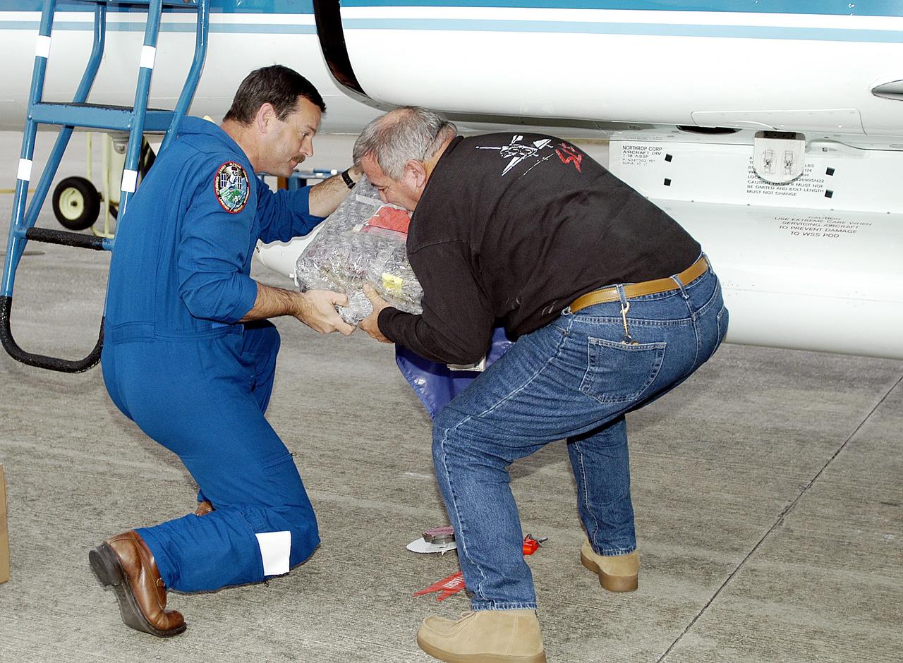
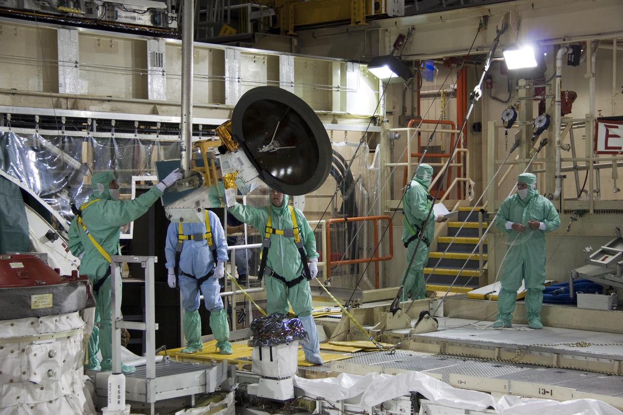
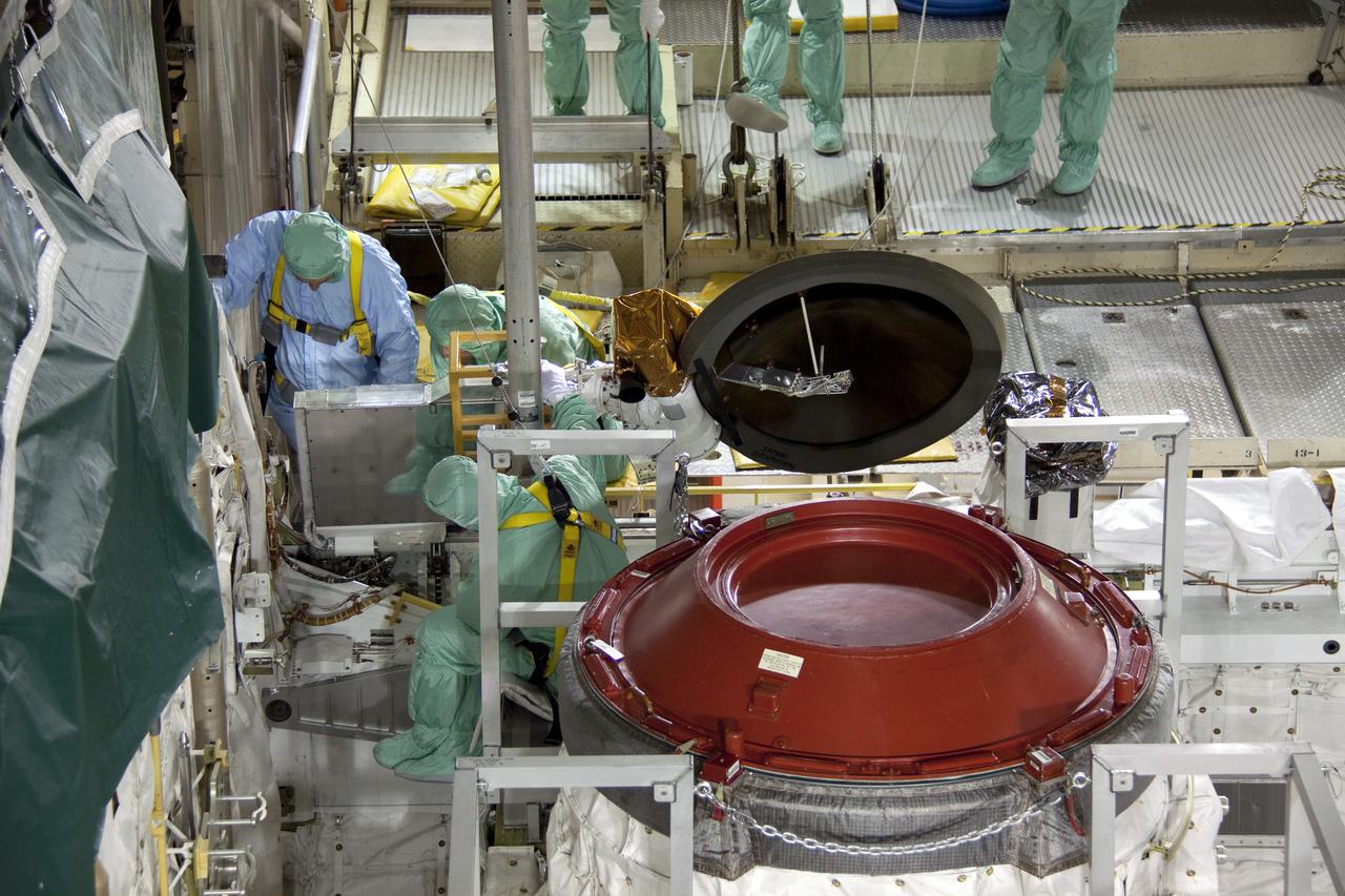
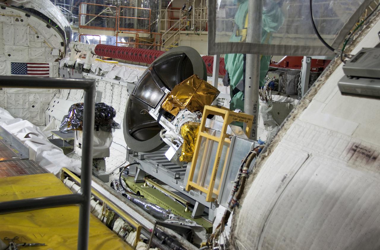
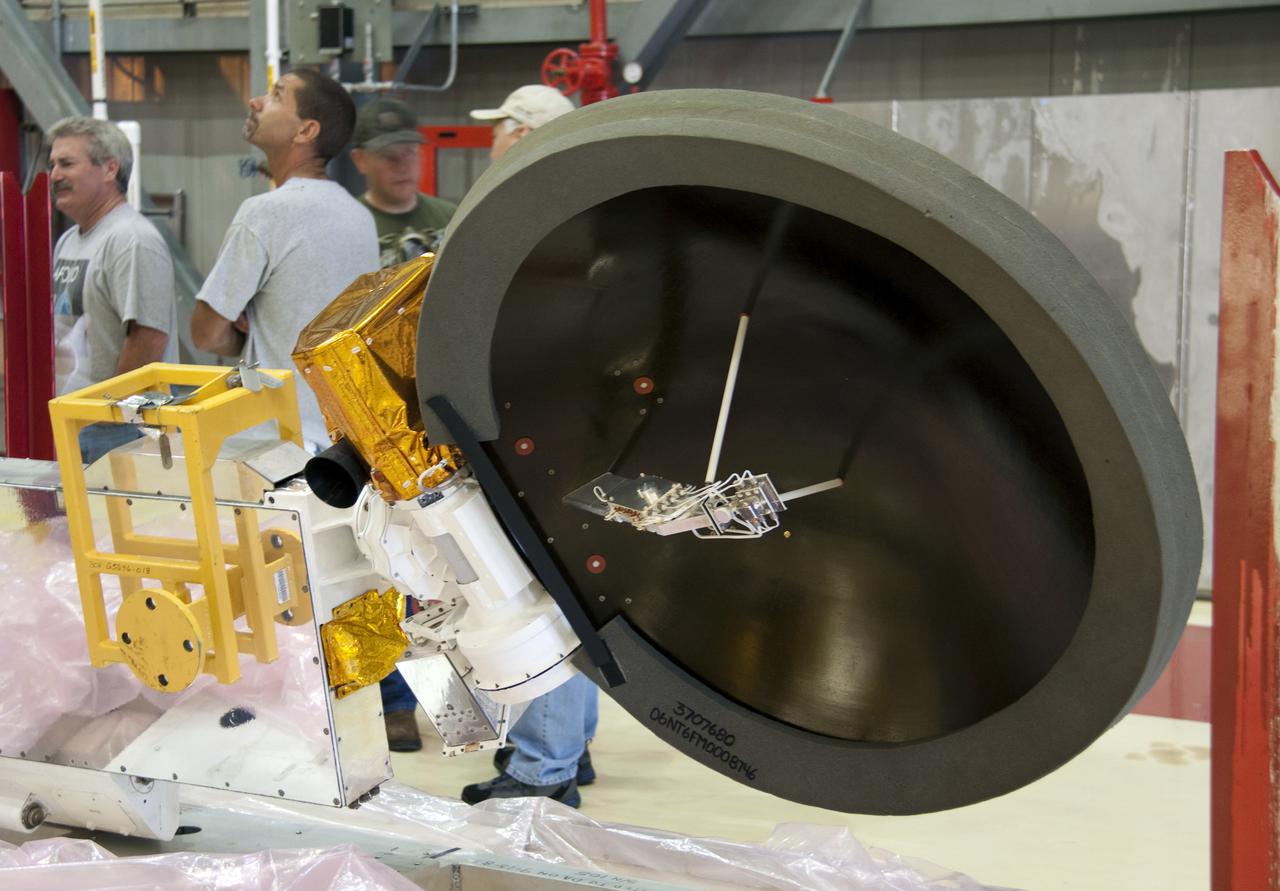
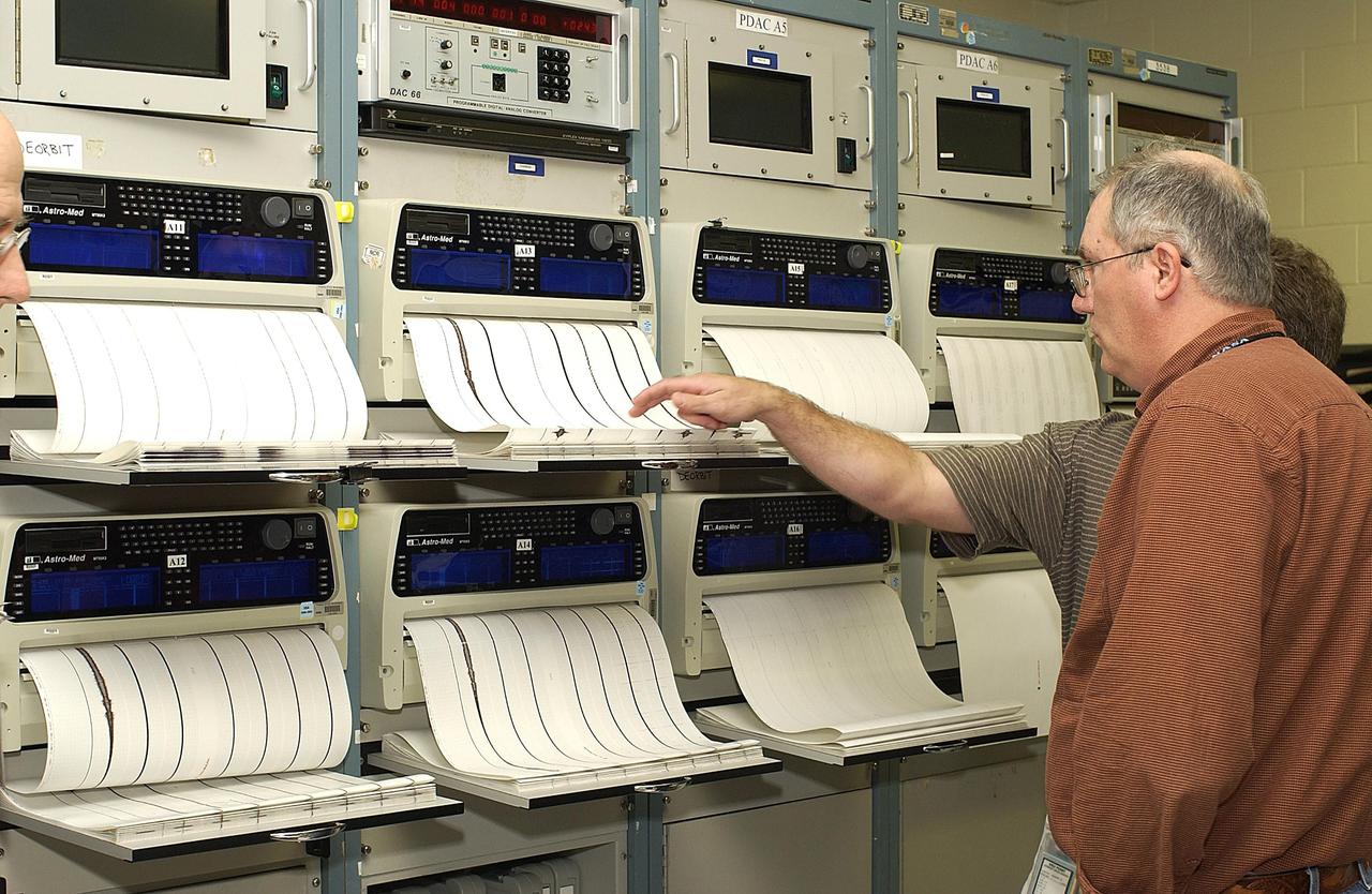
KENNEDY SPACE CENTER, FLA. - The Orbiter Experiment Support System (OEX) recorder from Columbia is removed from the T-38 jet aircraft that brought it to KSC. Search teams near Hemphill, Texas, recovered the recorder, which stores sensor information about temperature, aerodynamic pressure, vibrations and other data from dozens of sensor locations on the orbiter, operating only during launch and re-entry. The OEX uses magnetic tape to record data that is not sent to the ground by telemetry.
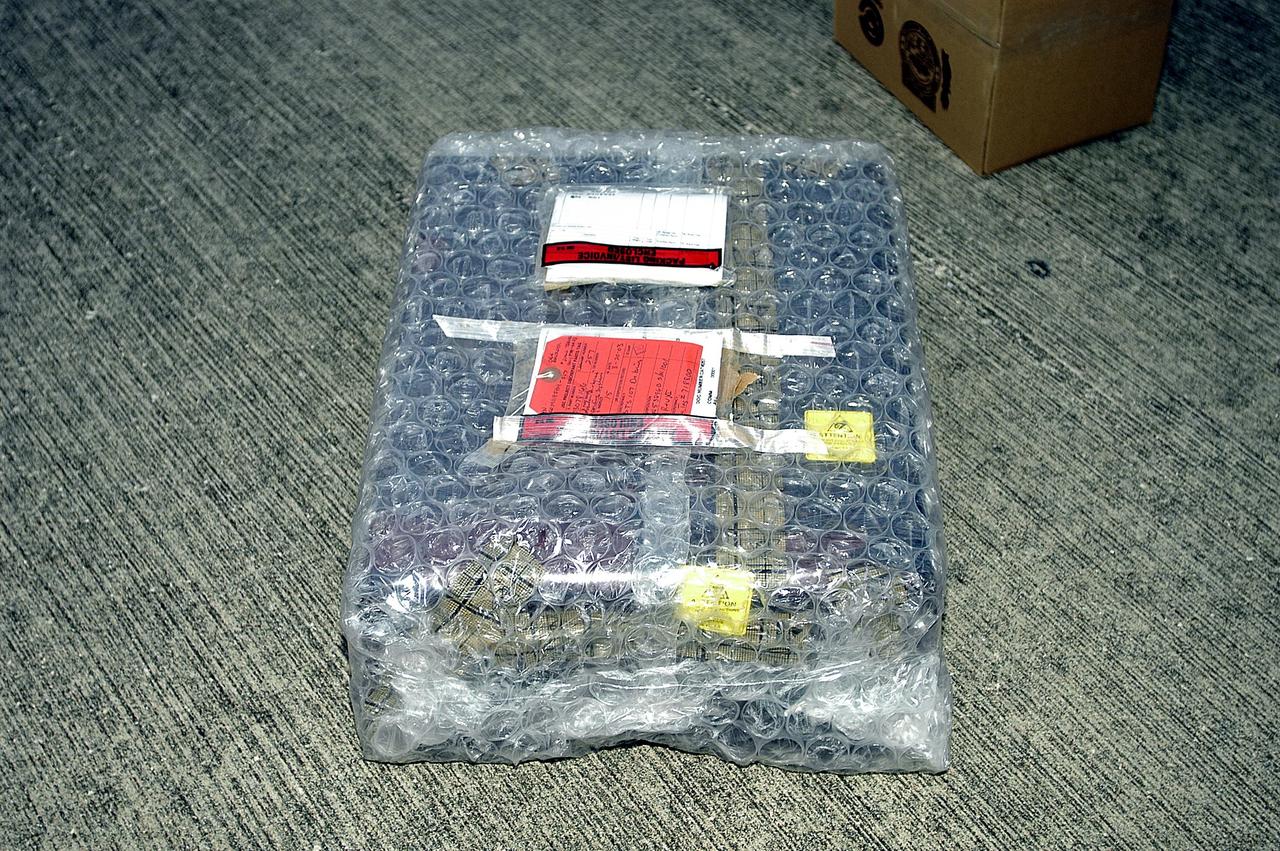
KENNEDY SPACE CENTER, FLA. - The Orbiter Experiment Support System (OEX) recorder from Columbia, in protective covering, sits on the pavement after its arrival at KSC aboard a T-38 jet aircraft. Search teams near Hemphill, Texas, recovered the recorder, which stores sensor information about temperature, aerodynamic pressure, vibrations and other data from dozens of sensor locations on the orbiter, operating only during launch and re-entry. The OEX uses magnetic tape to record data that is not sent to the ground by telemetry.
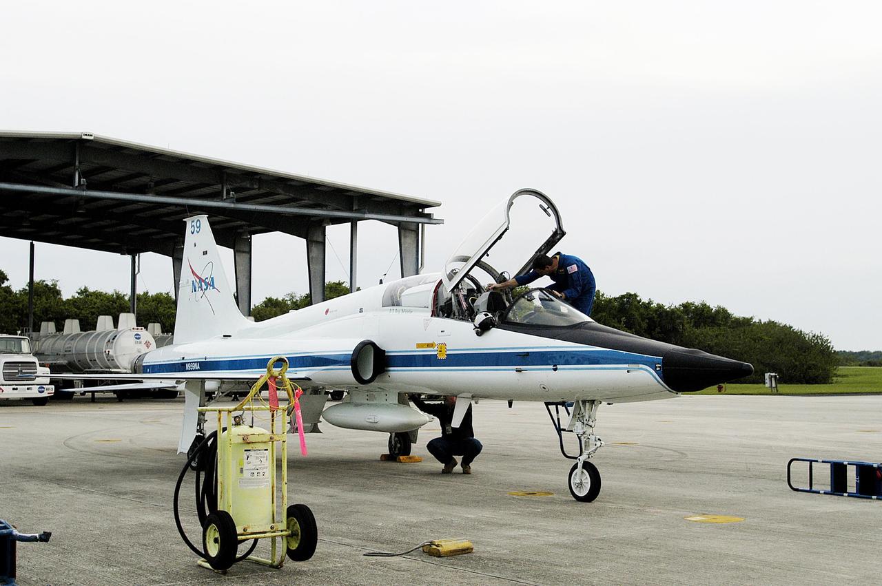
KENNEDY SPACE CENTER, FLA. -- A T-38 jet aircraft carrying the Orbiter Experiment Support System (OEX) recorder from Columbia arrives at the Shuttle Landing Facility. Search teams near Hemphill, Texas, recovered the recorder, which stores sensor information about temperature, aerodynamic pressure, vibrations and other data from dozens of sensor locations on the orbiter, operating only during launch and re-entry. The OEX uses magnetic tape to record data that is not sent to the ground by telemetry.
CAPE CANAVERAL, Fla. -- Technicians install a new Ku-Band communications system antenna on space shuttle Discovery in Orbiter Processing Facility-3 at NASA's Kennedy Space Center in Florida. The antenna is used to transmit and receive high data rate communications, such as video, and is being replaced for the STS-133 mission to the International Space Station. During its STS-131 mission to the station in April, Discovery's Ku-Band failed to operate in orbit. As a result, video of the thermal protection system inspection had to be recorded aboard Discovery and transmitted to the ground after the shuttle docked with the station. Typically, the inspection video is simultaneously transmitted live to the ground and recorded aboard the shuttle for later review. NASA_Charisse Nahser
CAPE CANAVERAL, Fla. -- Technicians install a new Ku-Band communications system antenna on space shuttle Discovery in Orbiter Processing Facility-3 at NASA's Kennedy Space Center in Florida. The antenna is used to transmit and receive high data rate communications, such as video, and is being replaced for the STS-133 mission to the International Space Station. During its STS-131 mission to the station in April, Discovery's Ku-Band failed to operate in orbit. As a result, video of the thermal protection system inspection had to be recorded aboard Discovery and transmitted to the ground after the shuttle docked with the station. Typically, the inspection video is simultaneously transmitted live to the ground and recorded aboard the shuttle for later review. NASA_Charisse Nahser
CAPE CANAVERAL, Fla. -- A new Ku-Band communications system antenna is installed on space shuttle Discovery in Orbiter Processing Facility-3 at NASA's Kennedy Space Center in Florida. The antenna is used to transmit and receive high data rate communications, such as video, and is being replaced for the STS-133 mission to the International Space Station. During its STS-131 mission to the station in April, Discovery's Ku-Band failed to operate in orbit. As a result, video of the thermal protection system inspection had to be recorded aboard Discovery and transmitted to the ground after the shuttle docked with the station. Typically, the inspection video is simultaneously transmitted live to the ground and recorded aboard the shuttle for later review. NASA_Charisse Nahser
CAPE CANAVERAL, Fla. -- A new Ku-Band communications system antenna is ready to be installed on space shuttle Discovery in Orbiter Processing Facility-3 at NASA's Kennedy Space Center in Florida. The antenna is used to transmit and receive high data rate communications, such as video, and is being replaced for the STS-133 mission to the International Space Station. During its STS-131 mission to the station in April, Discovery's Ku-Band failed to operate in orbit. As a result, video of the thermal protection system inspection had to be recorded aboard Discovery and transmitted to the ground after the shuttle docked with the station. Typically, the inspection video is simultaneously transmitted live to the ground and recorded aboard the shuttle for later review. NASA_Charisse Nahser

Guinness World Records officially designated NASA’s Crawler Transporter 2 as the heaviest self-powered vehicle, weighing approximately 6.65 million pounds. During a March 29, 2023, ceremony at the agency's Kennedy Space Center in Florida, Guinness World Records presented a certificate to teams with the Exploration Ground Systems Program and Kennedy leadership. The crawler is responsible for carrying the Space Launch System rocket and Orion spacecraft for the Artemis missions to and from the launch pad.
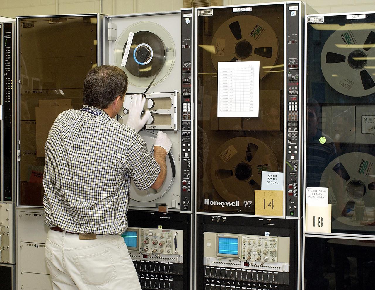
KENNEDY SPACE CENTER, FLA. -- Columbia's Orbiter Experiment Support System (OEX) recorder is put on taping equipment in the KSC Launch Control Center. The recorder tape is being duplicated and will be reviewed at the Johnson Space Center in Houston and other facilities. No actual sensor data on that tape has been reviewed at this time, Search teams near Hemphill, Texas recovered the recorder, which stores sensor information about temperature, aerodynamic pressure, vibrations and other data from dozens of sensor locations on the orbiter, operating only during launch and re-entry. The OEX uses magnetic tape to record data that is not sent to the ground by telemetry.
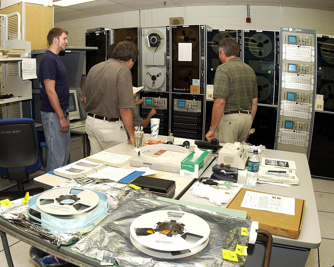
KENNEDY SPACE CENTER, FLA. - Workers in the KSC Launch Control Center watch the taping operation involving Columbia's Orbiter Experiment Support System (OEX) recorder. After duplication the tape will be reviewed at the Johnson Space Center in Houston and other facilities. No actual sensor data on that tape has been reviewed at this time. Search teams near Hemphill, Texas recovered the recorder, which stores sensor information about temperature, aerodynamic pressure, vibrations and other data from dozens of sensor locations on the orbiter, operating only during launch and re-entry. The OEX uses magnetic tape to record data that is not sent to the ground by telemetry.
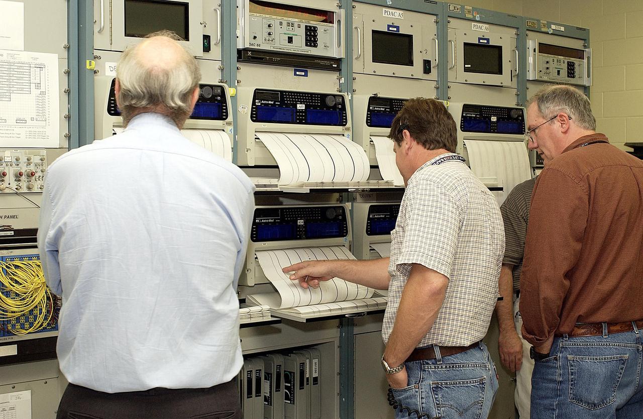
KENNEDY SPACE CENTER, FLA. - Workers in the KSC Launch Control Center look at the printout from Columbia's Orbiter Experiment Support System (OEX) recorder. After duplication the tape will be reviewed at the Johnson Space Center in Houston and other facilities. No actual sensor data on that tape has been reviewed at this time. Search teams near Hemphill, Texas recovered the recorder, which stores sensor information about temperature, aerodynamic pressure, vibrations and other data from dozens of sensor locations on the orbiter, operating only during launch and re-entry. The OEX uses magnetic tape to record data that is not sent to the ground by telemetry.
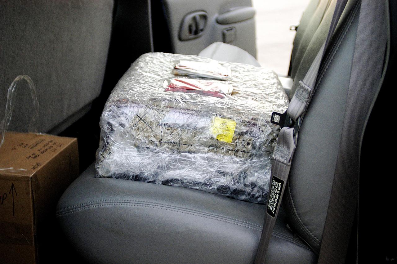
KENNEDY SPACE CENTER, FLA. - The Orbiter Experiment Support System (OEX) recorder from Columbia, in protective covering, rests inside a transport vehicle after its arrival at KSC aboard a T-38 jet aircraft. Search teams near Hemphill, Texas, recovered the recorder, which stores sensor information about temperature, aerodynamic pressure, vibrations and other data from dozens of sensor locations on the orbiter, operating only during launch and re-entry. The OEX uses magnetic tape to record data that is not sent to the ground by telemetry.
KENNEDY SPACE CENTER, FLA. - Workers in the KSC Launch Control Center look at the printout from Columbia's Orbiter Experiment Support System (OEX) recorder. After duplication the tape will be reviewed at the Johnson Space Center in Houston and other facilities. No actual sensor data on that tape has been reviewed at this time. Search teams near Hemphill, Texas recovered the recorder, which stores sensor information about temperature, aerodynamic pressure, vibrations and other data from dozens of sensor locations on the orbiter, operating only during launch and re-entry. The OEX uses magnetic tape to record data that is not sent to the ground by telemetry.
CAPE CANAVERAL, Fla. -- Technicians prepare to install a new Ku-Band communications system antenna on space shuttle Discovery in Orbiter Processing Facility-3 at NASA's Kennedy Space Center in Florida. The antenna is used to transmit and receive high data rate communications, such as video, and is being replaced for the STS-133 mission to the International Space Station. During its STS-131 mission to the station in April, Discovery's Ku-Band failed to operate in orbit. As a result, video of the thermal protection system inspection had to be recorded aboard Discovery and transmitted to the ground after the shuttle docked with the station. Typically, the inspection video is simultaneously transmitted live to the ground and recorded aboard the shuttle for later review. NASA_Charisse Nahser
CAPE CANAVERAL, Fla. -- Technicians prepare to install a new Ku-Band communications system antenna on space shuttle Discovery in Orbiter Processing Facility-3 at NASA's Kennedy Space Center in Florida. The antenna is used to transmit and receive high data rate communications, such as video, and is being replaced for the STS-133 mission to the International Space Station. During its STS-131 mission to the station in April, Discovery's Ku-Band failed to operate in orbit. As a result, video of the thermal protection system inspection had to be recorded aboard Discovery and transmitted to the ground after the shuttle docked with the station. Typically, the inspection video is simultaneously transmitted live to the ground and recorded aboard the shuttle for later review. NASA_Charisse Nahser
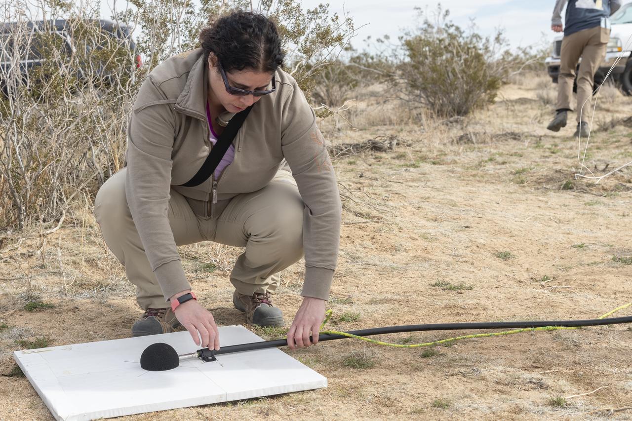
Dr. Alexandra Loubeau, one of the technical co-leads for sonic boom community testing for the Quesst mission, sets out a microphone in the California desert. . The Quesst mission recently completed testing of operations and equipment to be used in recording the sonic thumps of the X-59. The testing was the third phase of Carpet Determination in Entirety Measurements flights, called CarpetDIEM for short. An F-15 and an F-18 from NASA’s Armstrong Flight Research Center created sonic booms, both loud and soft, to verify the operations of ground recording systems spread out across 30 miles of open desert.

Dr. Forrest Carpenter, left, principal investigator for the third phase of CarpetDIEM, Carpet Determination in Entirety Measurements flights, monitors a test from one of the control rooms at NASA’s Armstrong Flight Research Center. Next to Carpenter is Brian Strovers, chief engineer for Commercial Supersonic Technology. The third phase of CarpetDIEM tested logistics and upgraded ground recording systems in preparation for the acoustic validation phase of the Quesst mission.

CAPE CANAVERAL, Fla. --- STS-123 Commander Dominic Gorie talks to the media about his experiences on the mission to the International Space Station. The crew landed at Kennedy aboard space shuttle Endeavour at 8:39 p.m. EDT March 26. Endeavour's 16-day flight was the longest shuttle mission to the International Space Station and included a record five spacewalks. The shuttle's seven astronauts worked with the three-member station crew and ground teams around the world to install the first section of the Japan Aerospace Exploration Agency's Kibo laboratory and the Canadian Space Agency's two-armed robotic system, known as Dextre. Photo credit: NASA/Kim Shiflett
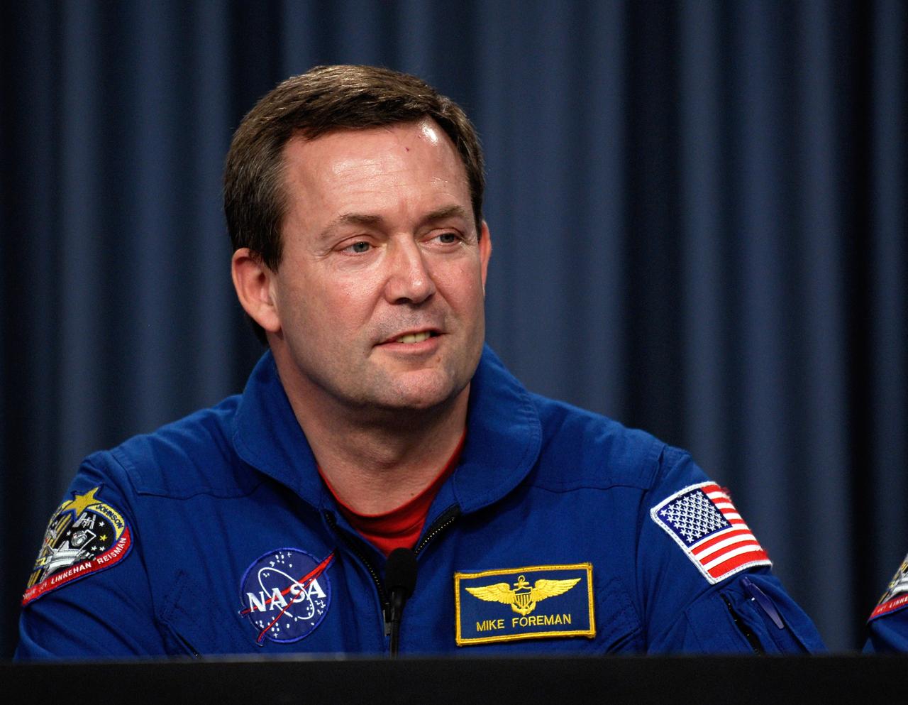
CAPE CANAVERAL, Fla. --- STS-123 Mission Specialist Mike Foreman talks to the media about his experiences on the mission to the International Space Station. The crew landed at Kennedy aboard space shuttle Endeavour at 8:39 p.m. EDT March 26. Endeavour's 16-day flight was the longest shuttle mission to the International Space Station and included a record five spacewalks. The shuttle's seven astronauts worked with the three-member station crew and ground teams around the world to install the first section of the Japan Aerospace Exploration Agency's Kibo laboratory and the Canadian Space Agency's two-armed robotic system, known as Dextre. Photo credit: NASA/Kim Shiflett
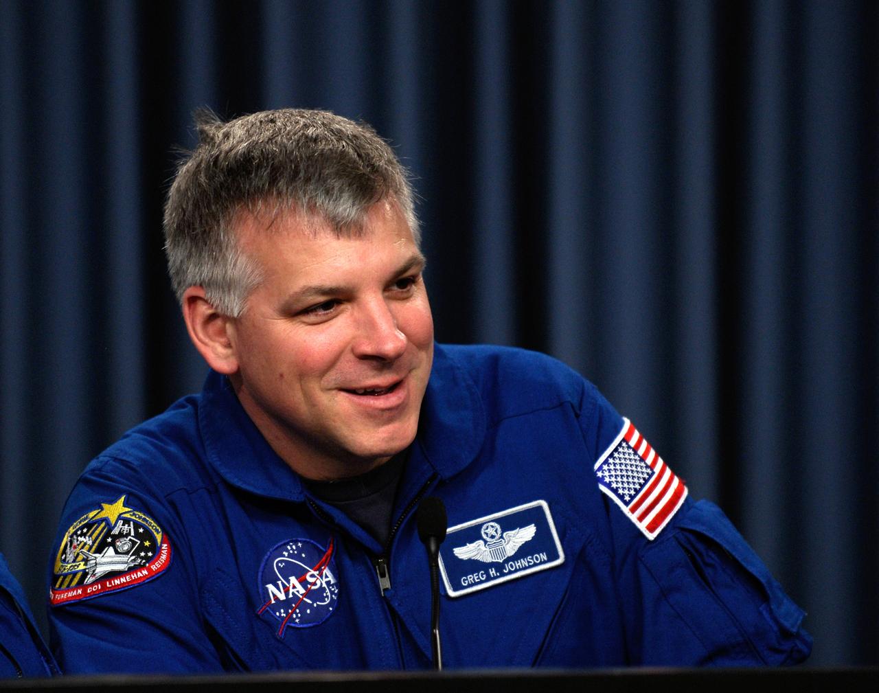
CAPE CANAVERAL, Fla. --- STS-123 Pilot Gregory H. Johnson talks to the media about his experiences on the mission to the International Space Station. The crew landed at Kennedy aboard space shuttle Endeavour at 8:39 p.m. EDT March 26. Endeavour's 16-day flight was the longest shuttle mission to the International Space Station and included a record five spacewalks. The shuttle's seven astronauts worked with the three-member station crew and ground teams around the world to install the first section of the Japan Aerospace Exploration Agency's Kibo laboratory and the Canadian Space Agency's two-armed robotic system, known as Dextre. Photo credit: NASA/Kim Shiflett
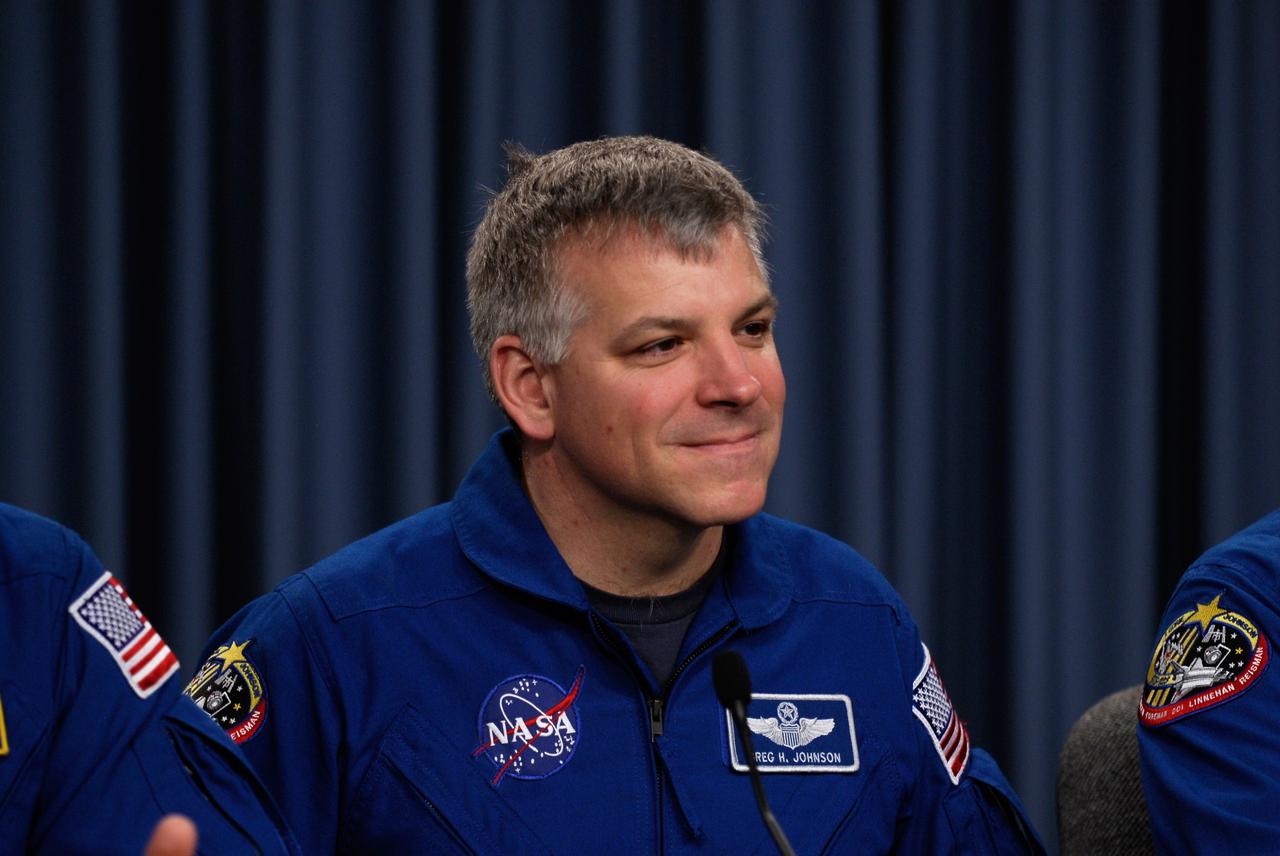
CAPE CANAVERAL, Fla. --- STS-123 Pilot Gregory H. Johnson talks to the media about his experiences on the mission to the International Space Station. The crew landed at Kennedy aboard space shuttle Endeavour at 8:39 p.m. EDT March 26. Endeavour's 16-day flight was the longest shuttle mission to the International Space Station and included a record five spacewalks. The shuttle's seven astronauts worked with the three-member station crew and ground teams around the world to install the first section of the Japan Aerospace Exploration Agency's Kibo laboratory and the Canadian Space Agency's two-armed robotic system, known as Dextre. Photo credit: NASA/Kim Shiflett

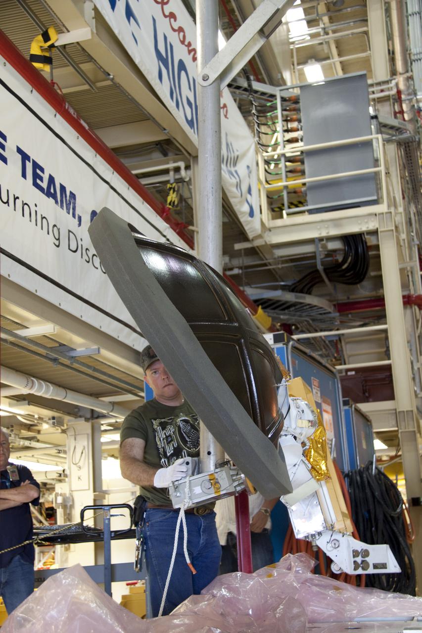
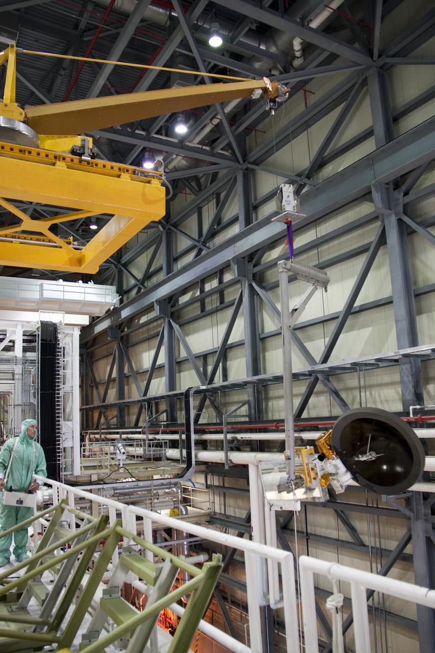
Thermal blanket technicians, Aldine Joseph-pierre and Paula Cain, adjust blankets on the Ocean Color Instrument (OCI) in preparation for metrology on the Ground Support Equipment Application for Tilt or Rotation (GATOR). OCI is a highly advanced optical spectrometer that will be used to measure properties of light over portions of the electromagnetic spectrum. It will enable continuous measurement of light at finer wavelength resolution than previous NASA satellite sensors, extending key system ocean color data records for climate studies. OCI is PACE's (Plankton, Aerosol, Cloud, ocean Ecosystem) primary sensor built at Goddard Space Flight Center in Greenbelt, MD.
CAPE CANAVERAL, Fla. – Crawler-transporter 2, or CT-2, nears the entrance to the Vehicle Assembly Building at NASA’s Kennedy Space Center in Florida. The Ground Systems Development and Operations Program completed a roller bearing assembly test on CT-2 truck sections A and C. The left- and right-hand steering was tested in both directions. The temperature of the roller assemblies was monitored and recorded as it traveled along the crawlerway. Engineers and technicians performed visual inspections of the roller bearing pumps, valves and lines to ensure that the grease injectors worked properly and provided the required flow of grease to the new roller assemblies. Work continues in high bay 2 to upgrade CT-2. The modifications are designed to ensure CT-2’s ability to transport launch vehicles currently in development, such as the agency’s Space Launch System, to the launch pad. The Ground Systems Development and Operations Program office at Kennedy is overseeing the upgrades. For more than 45 years the crawler-transporters were used to transport the mobile launcher platform and the Apollo-Saturn V rockets and, later, space shuttles to Launch Pads 39A and B. For more information, visit: http:__www.nasa.gov_exploration_systems_ground_crawler-transporter. Photo credit: NASA_Kim Shiflett
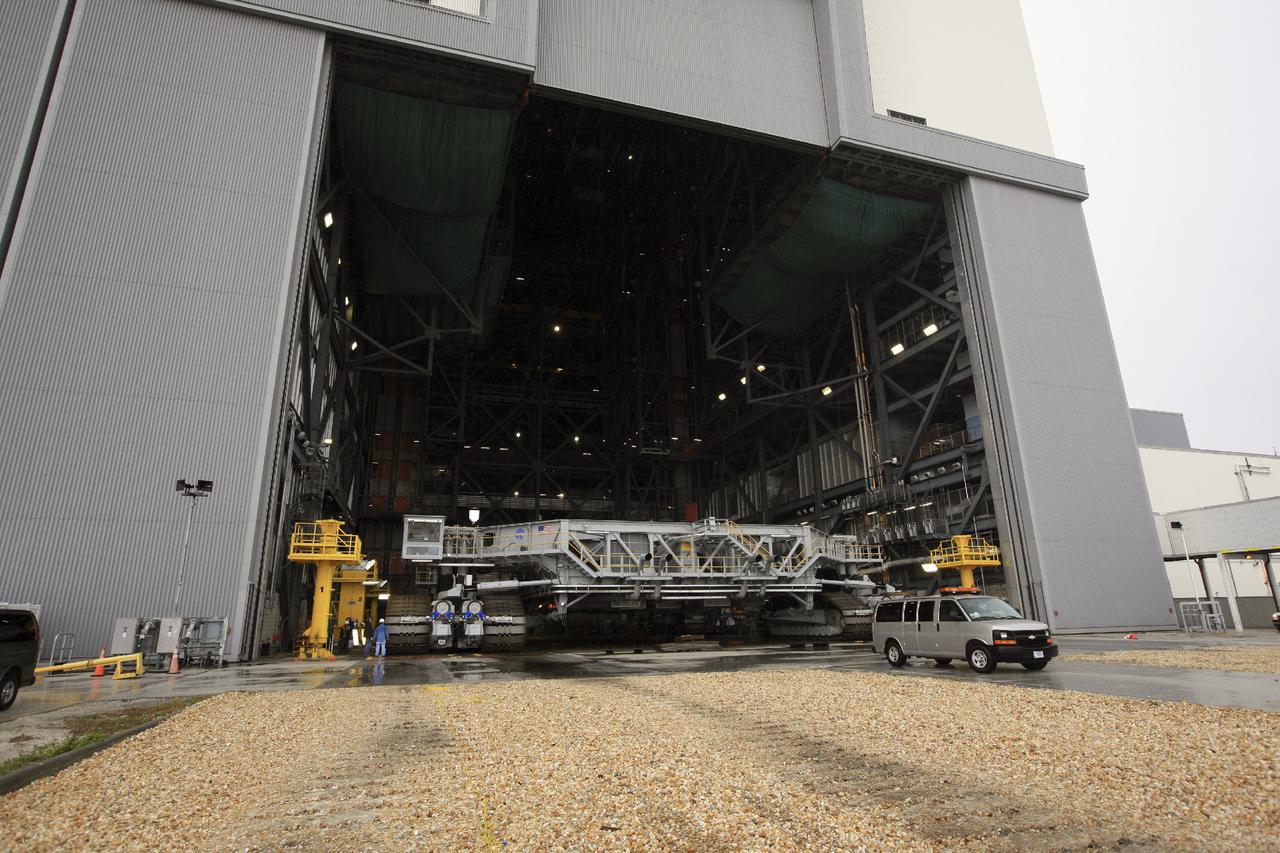
CAPE CANAVERAL, Fla. – Crawler-transporter 2, or CT-2, slowly enters the Vehicle Assembly Building at NASA’s Kennedy Space Center in Florida. The Ground Systems Development and Operations Program completed a roller bearing assembly test on CT-2 truck sections A and C. The left- and right-hand steering was tested in both directions. The temperature of the roller assemblies was monitored and recorded as it traveled along the crawlerway. Engineers and technicians performed visual inspections of the roller bearing pumps, valves and lines to ensure that the grease injectors worked properly and provided the required flow of grease to the new roller assemblies. Work continues in high bay 2 to upgrade CT-2. The modifications are designed to ensure CT-2’s ability to transport launch vehicles currently in development, such as the agency’s Space Launch System, to the launch pad. The Ground Systems Development and Operations Program office at Kennedy is overseeing the upgrades. For more than 45 years the crawler-transporters were used to transport the mobile launcher platform and the Apollo-Saturn V rockets and, later, space shuttles to Launch Pads 39A and B. For more information, visit: http:__www.nasa.gov_exploration_systems_ground_crawler-transporter. Photo credit: NASA_Kim Shiflett
CAPE CANAVERAL, Fla. – Crawler-transporter 2, or CT-2, enters the Vehicle Assembly Building at NASA’s Kennedy Space Center in Florida. Visible are the new roller bearing assemblies that were installed on one side of the crawler. The Ground Systems Development and Operations Program completed a roller bearing assembly test on CT-2 truck sections A and C. The left- and right-hand steering was tested in both directions. The temperature of the roller assemblies was monitored and recorded as it traveled along the crawlerway. Engineers and technicians performed visual inspections of the roller bearing pumps, valves and lines to ensure that the grease injectors worked properly and provided the required flow of grease to the new roller assemblies. Work continues in high bay 2 to upgrade CT-2. The modifications are designed to ensure CT-2’s ability to transport launch vehicles currently in development, such as the agency’s Space Launch System, to the launch pad. The Ground Systems Development and Operations Program office at Kennedy is overseeing the upgrades. For more than 45 years the crawler-transporters were used to transport the mobile launcher platform and the Apollo-Saturn V rockets and, later, space shuttles to Launch Pads 39A and B. For more information, visit: http:__www.nasa.gov_exploration_systems_ground_crawler-transporter. Photo credit: NASA_Kim Shiflett
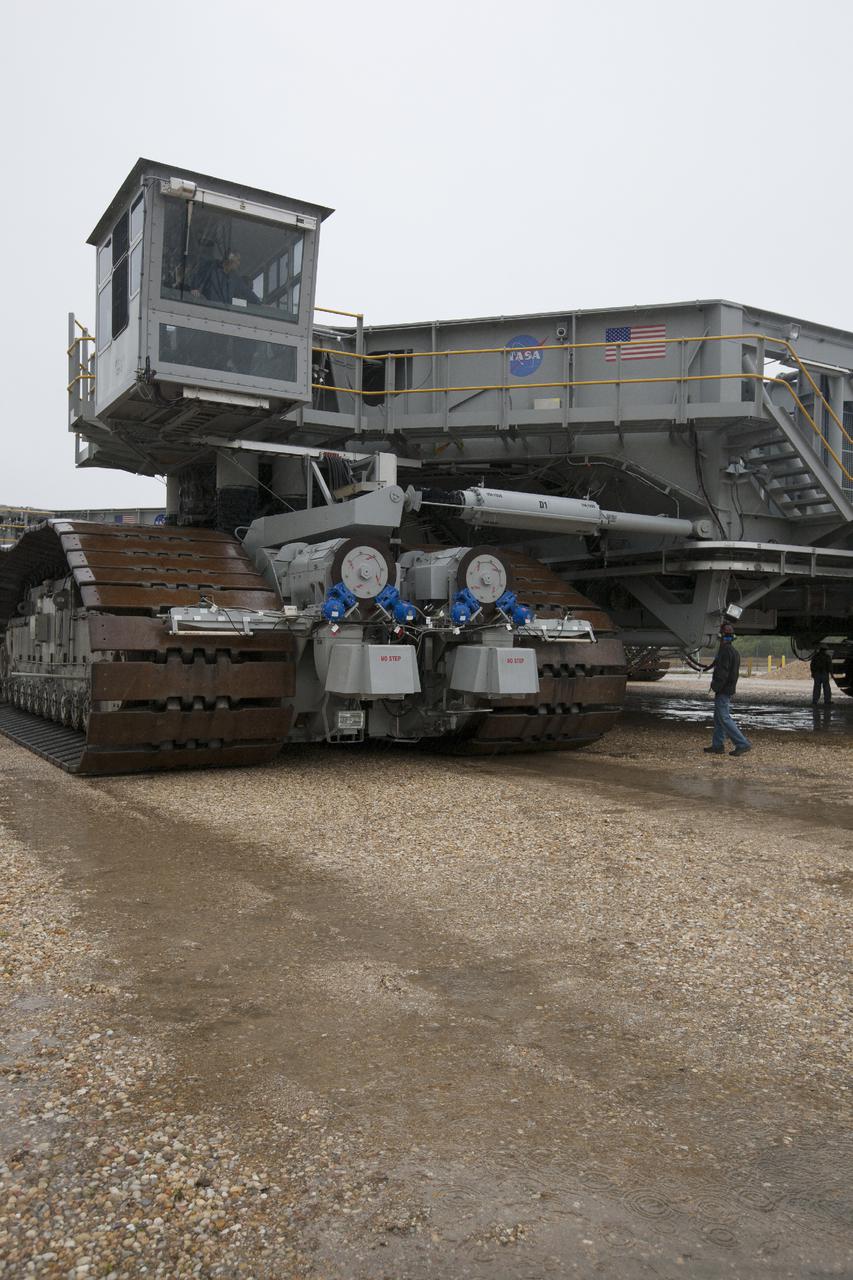
CAPE CANAVERAL, Fla. – A technician in the cab of crawler-transporter 2, or CT-2, drives along the crawlerway toward the Vehicle Assembly Building at NASA’s Kennedy Space Center in Florida. The Ground Systems Development and Operations Program completed a roller bearing assembly test on CT-2 truck sections A and C. The left- and right-hand steering was tested in both directions. The temperature of the roller assemblies was monitored and recorded. Engineers and technicians performed visual inspections of the roller bearing pumps, valves and lines to ensure that the grease injectors worked properly and provided the required flow of grease to the new roller assemblies. Work continues in high bay 2 to upgrade CT-2. The modifications are designed to ensure CT-2’s ability to transport launch vehicles currently in development, such as the agency’s Space Launch System, to the launch pad. The Ground Systems Development and Operations Program office at Kennedy is overseeing the upgrades. For more than 45 years the crawler-transporters were used to transport the mobile launcher platform and the Apollo-Saturn V rockets and, later, space shuttles to Launch Pads 39A and B. For more information, visit: http:__www.nasa.gov_exploration_systems_ground_crawler-transporter. Photo credit: NASA_Kim Shiflett
CAPE CANAVERAL, Fla. – Crawler-transporter 2, or CT-2, nears the entrance to the Vehicle Assembly Building at NASA’s Kennedy Space Center in Florida. The Ground Systems Development and Operations Program completed a roller bearing assembly test on CT-2 truck sections A and C. The left- and right-hand steering was tested in both directions. The temperature of the roller assemblies was monitored and recorded as it traveled along the crawlerway. Engineers and technicians performed visual inspections of the roller bearing pumps, valves and lines to ensure that the grease injectors worked properly and provided the required flow of grease to the new roller assemblies. Work continues in high bay 2 to upgrade CT-2. The modifications are designed to ensure CT-2’s ability to transport launch vehicles currently in development, such as the agency’s Space Launch System, to the launch pad. The Ground Systems Development and Operations Program office at Kennedy is overseeing the upgrades. For more than 45 years the crawler-transporters were used to transport the mobile launcher platform and the Apollo-Saturn V rockets and, later, space shuttles to Launch Pads 39A and B. For more information, visit: http:__www.nasa.gov_exploration_systems_ground_crawler-transporter. Photo credit: NASA_Kim Shiflett
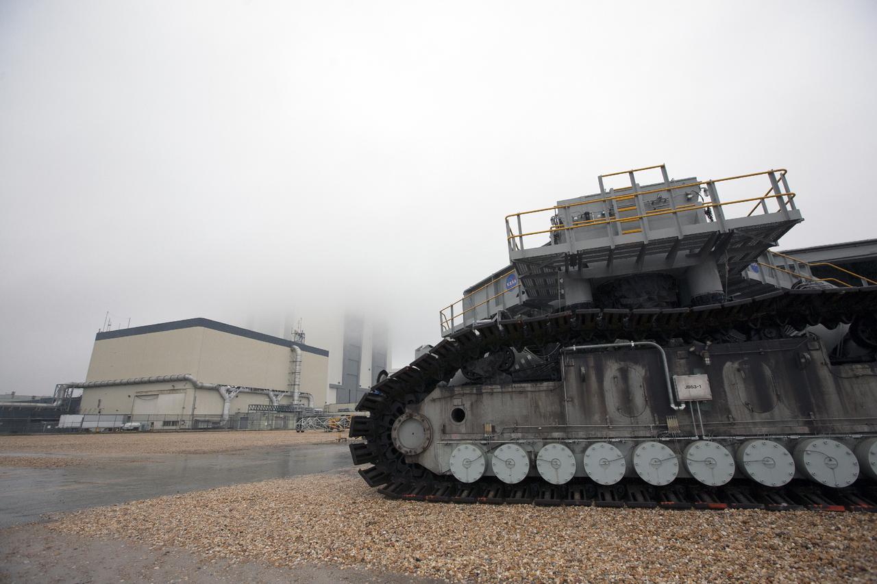
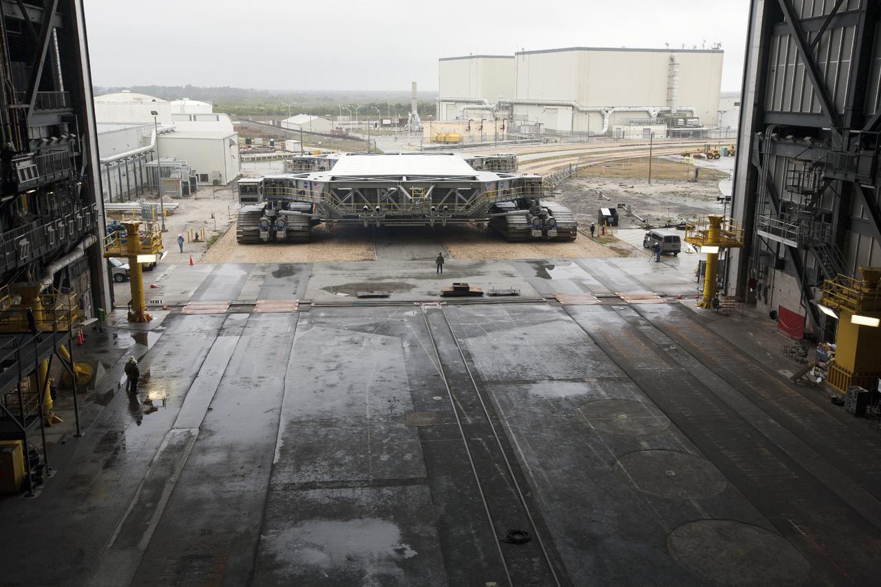
CAPE CANAVERAL, Fla. – Crawler-transporter 2, or CT-2, travels along the crawlerway toward the Vehicle Assembly Building, or VAB, at NASA’s Kennedy Space Center in Florida. The VAB is partially hidden by fog. The Ground Systems Development and Operations Program completed a roller bearing assembly test on CT-2 truck sections A and C. The left- and right-hand steering was tested in both directions. The temperature of the roller assemblies was monitored and recorded. Engineers and technicians performed visual inspections of the roller bearing pumps, valves and lines to ensure that the grease injectors worked properly and provided the required flow of grease to the new roller assemblies. Work continues in high bay 2 to upgrade CT-2. The modifications are designed to ensure CT-2’s ability to transport launch vehicles currently in development, such as the agency’s Space Launch System, to the launch pad. The Ground Systems Development and Operations Program office at Kennedy is overseeing the upgrades. For more than 45 years the crawler-transporters were used to transport the mobile launcher platform and the Apollo-Saturn V rockets and, later, space shuttles to Launch Pads 39A and B. For more information, visit: http:__www.nasa.gov_exploration_systems_ground_crawler-transporter. Photo credit: NASA_Kim Shiflett

CAPE CANAVERAL, Fla. – Crawler-transporter 2, or CT-2, travels along the crawlerway toward the Vehicle Assembly Building at NASA’s Kennedy Space Center in Florida. The Ground Systems Development and Operations Program completed a roller bearing assembly test on CT-2 truck sections A and C. The left- and right-hand steering was tested in both directions. The temperature of the roller assemblies was monitored and recorded as it traveled along the crawlerway. Engineers and technicians performed visual inspections of the roller bearing pumps, valves and lines to ensure that the grease injectors worked properly and provided the required flow of grease to the new roller assemblies. Work continues in high bay 2 to upgrade CT-2. The modifications are designed to ensure CT-2’s ability to transport launch vehicles currently in development, such as the agency’s Space Launch System, to the launch pad. The Ground Systems Development and Operations Program office at Kennedy is overseeing the upgrades. For more than 45 years the crawler-transporters were used to transport the mobile launcher platform and the Apollo-Saturn V rockets and, later, space shuttles to Launch Pads 39A and B. For more information, visit: http:__www.nasa.gov_exploration_systems_ground_crawler-transporter. Photo credit: NASA_Kim Shiflett
CAPE CANAVERAL, Fla. – Crawler-transporter 2, or CT-2, travels along the crawlerway toward the Vehicle Assembly Building at NASA’s Kennedy Space Center in Florida. The Ground Systems Development and Operations Program completed a roller bearing assembly test on CT-2 truck sections A and C. The left- and right-hand steering was tested in both directions. The temperature of the roller assemblies was monitored and recorded. Engineers and technicians performed visual inspections of the roller bearing pumps, valves and lines to ensure that the grease injectors worked properly and provided the required flow of grease to the new roller assemblies. Work continues in high bay 2 to upgrade CT-2. The modifications are designed to ensure CT-2’s ability to transport launch vehicles currently in development, such as the agency’s Space Launch System, to the launch pad. The Ground Systems Development and Operations Program office at Kennedy is overseeing the upgrades. For more than 45 years the crawler-transporters were used to transport the mobile launcher platform and the Apollo-Saturn V rockets and, later, space shuttles to Launch Pads 39A and B. For more information, visit: http:__www.nasa.gov_exploration_systems_ground_crawler-transporter. Photo credit: NASA_Kim Shiflett
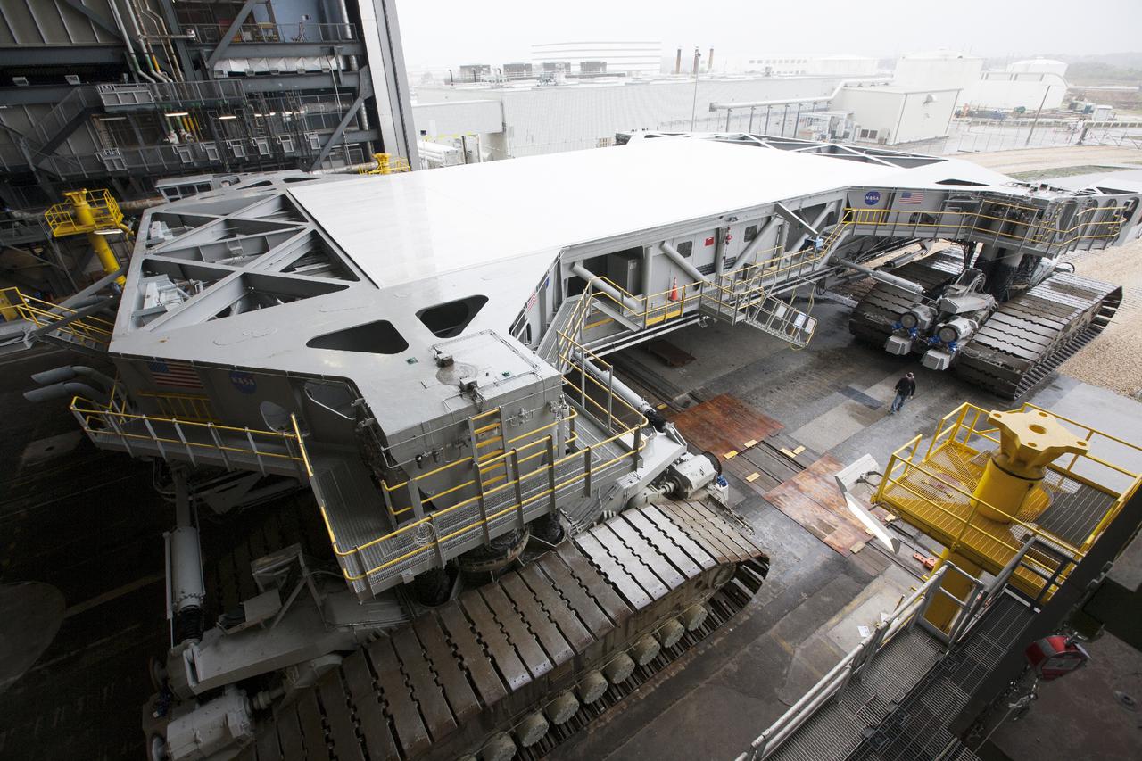
CAPE CANAVERAL, Fla. – Crawler-transporter 2, or CT-2, slowly enters the Vehicle Assembly Building at NASA’s Kennedy Space Center in Florida. The Ground Systems Development and Operations Program completed a roller bearing assembly test on CT-2 truck sections A and C. The left- and right-hand steering was tested in both directions. The temperature of the roller assemblies was monitored and recorded as it traveled along the crawlerway. Engineers and technicians performed visual inspections of the roller bearing pumps, valves and lines to ensure that the grease injectors worked properly and provided the required flow of grease to the new roller assemblies. Work continues in high bay 2 to upgrade CT-2. The modifications are designed to ensure CT-2’s ability to transport launch vehicles currently in development, such as the agency’s Space Launch System, to the launch pad. The Ground Systems Development and Operations Program office at Kennedy is overseeing the upgrades. For more than 45 years the crawler-transporters were used to transport the mobile launcher platform and the Apollo-Saturn V rockets and, later, space shuttles to Launch Pads 39A and B. For more information, visit: http:__www.nasa.gov_exploration_systems_ground_crawler-transporter. Photo credit: NASA_Kim Shiflett
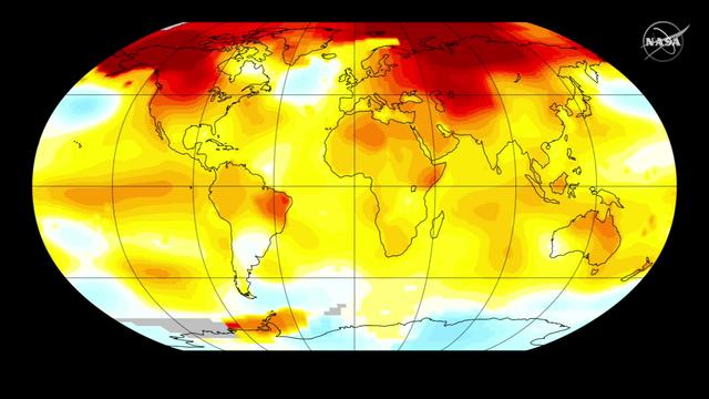
Two key climate change indicators -- global surface temperatures and Arctic sea ice extent -- have broken numerous records through the first half of 2016, according to NASA analyses of ground-based observations and satellite data. Each of the first six months of 2016 set a record as the warmest respective month globally in the modern temperature record, which dates to 1880, according to scientists at NASA's Goddard Institute for Space Studies (GISS) in New York. The six-month period from January to June was also the planet's warmest half-year on record, with an average temperature 1.3 degrees Celsius (2.4 degrees Fahrenheit) warmer than the late nineteenth century. Read more: <a href="http://go.nasa.gov/29SQngq" rel="nofollow">go.nasa.gov/29SQngq</a> Credit: NASA/Goddard <b><a href="http://www.nasa.gov/audience/formedia/features/MP_Photo_Guidelines.html" rel="nofollow">NASA image use policy.</a></b> <b><a href="http://www.nasa.gov/centers/goddard/home/index.html" rel="nofollow">NASA Goddard Space Flight Center</a></b> enables NASA’s mission through four scientific endeavors: Earth Science, Heliophysics, Solar System Exploration, and Astrophysics. Goddard plays a leading role in NASA’s accomplishments by contributing compelling scientific knowledge to advance the Agency’s mission. <b>Follow us on <a href="http://twitter.com/NASAGoddardPix" rel="nofollow">Twitter</a></b> <b>Like us on <a href="http://www.facebook.com/pages/Greenbelt-MD/NASA-Goddard/395013845897?ref=tsd" rel="nofollow">Facebook</a></b> <b>Find us on <a href="http://instagrid.me/nasagoddard/?vm=grid" rel="nofollow">Instagram</a></b>

CAPE CANAVERAL, Fla. --- STS-123 Mission Specialist Takao Doi talks to the media about his experiences on the mission to the International Space Station. Doi represents the Japan Aerospace Exploration Agency. The crew landed at Kennedy aboard space shuttle Endeavour at 8:39 p.m. EDT March 26. Endeavour's 16-day flight was the longest shuttle mission to the International Space Station and included a record five spacewalks. The shuttle's seven astronauts worked with the three-member station crew and ground teams around the world to install the first section of the Japan Aerospace Exploration Agency's Kibo laboratory and the Canadian Space Agency's two-armed robotic system, known as Dextre. Photo credit: NASA/Kim Shiflett
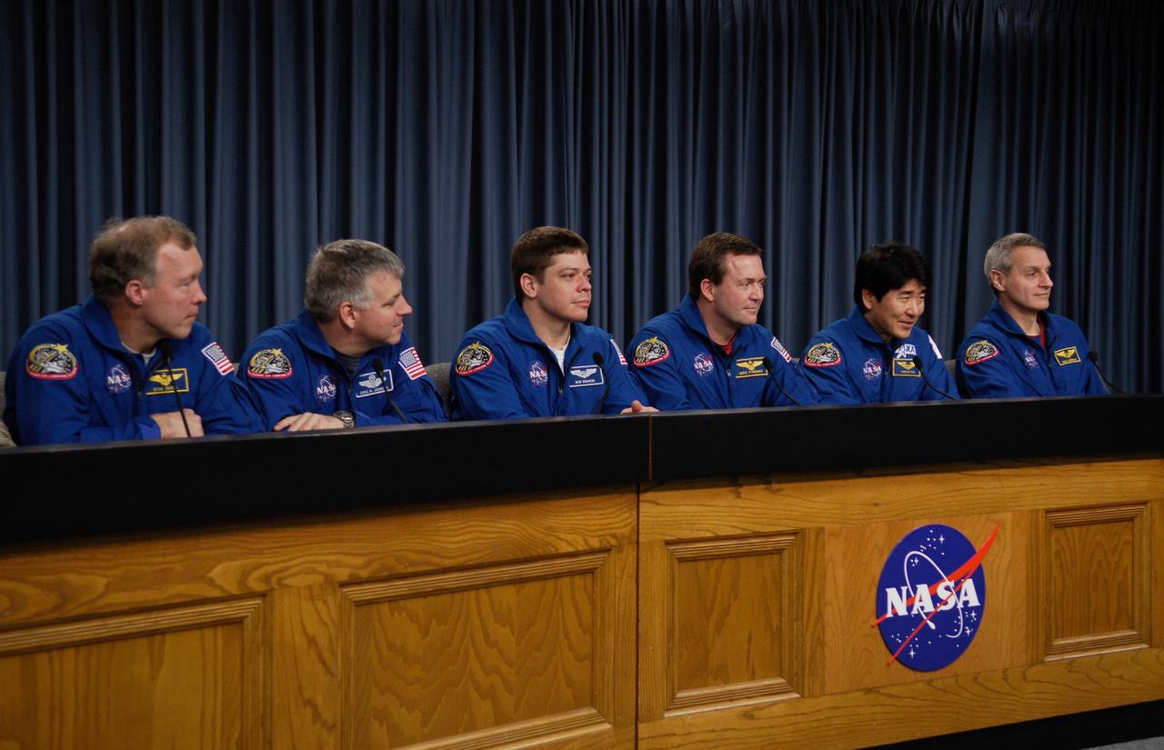
CAPE CANAVERAL, Fla. --- Space shuttle Endeavour crew members meet with the media to discuss their experiences on the STS-123 mission to the International Space Station. From left are Commander Dominic Gorie, Pilot Gregory H. Johnson, and Mission Specialists Robert L. Behnken, Mike Foreman, Japan Aerospace Exploration Agency astronaut Takao Doi and Rick Linnehan. They landed at Kennedy at 8:39 p.m. EDT March 26. Endeavour's 16-day flight was the longest shuttle mission to the International Space Station and included a record five spacewalks. The shuttle's seven astronauts worked with the three-member station crew and ground teams around the world to install the first section of the Japan Aerospace Exploration Agency's Kibo laboratory and the Canadian Space Agency's two-armed robotic system, known as Dextre. Photo credit: NASA/Kim Shiflett
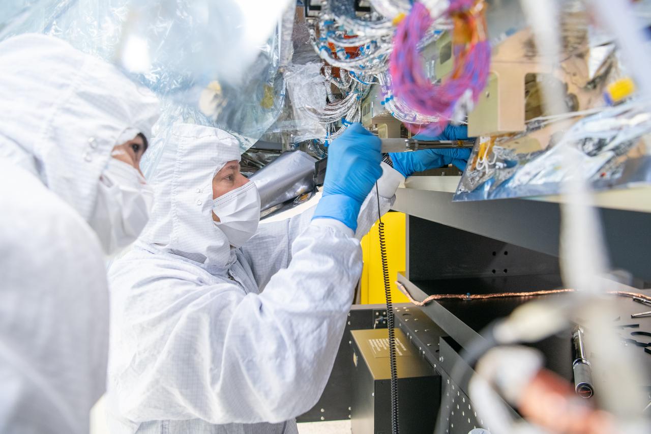
Mechanical technician, Thomas Huber, tightens bolts on the Ocean Color Instrument (OCI) is installed onto the Ground Support Equipment Application for Tilt or Rotation (GAToR) made by Newton Engineering. GAToR will allow engineers to tilt and rotate OCI in different orientations for further testing prior to integration onto the PACE (Plankton, Aerosol, Cloud, ocean Ecosystem) spacecraft. OCI is a highly advanced optical spectrometer that will be used to measure properties of light over portions of the electromagnetic spectrum. It will enable continuous measurement of light at finer wavelength resolution than previous NASA satellite sensors, extending key system ocean color data records for climate studies. OCI is PACE's (Plankton, Aerosol, Cloud, ocean Ecosystem) primary sensor built at Goddard Space Flight Center in Greenbelt, MD.

The Ocean Color Instrument (OCI) Electro-Magnetic Interference (EMI) & Electrical Ground Support Equipment (EGSE) Team pose in the control room. From this room, they are able to analyze the data from the test remotely and send commands through electrical cables that run through the walls into the EMI lab. OCI is a highly advanced optical spectrometer that will be used to measure properties of light over portions of the electromagnetic spectrum. It will enable continuous measurement of light at finer wavelength resolution than previous NASA satellite sensors, extending key system ocean color data records for climate studies. OCI is PACE's (Plankton, Aerosol, Cloud, ocean Ecosystem) primary sensor built at Goddard Space Flight Center in Greenbelt, MD.
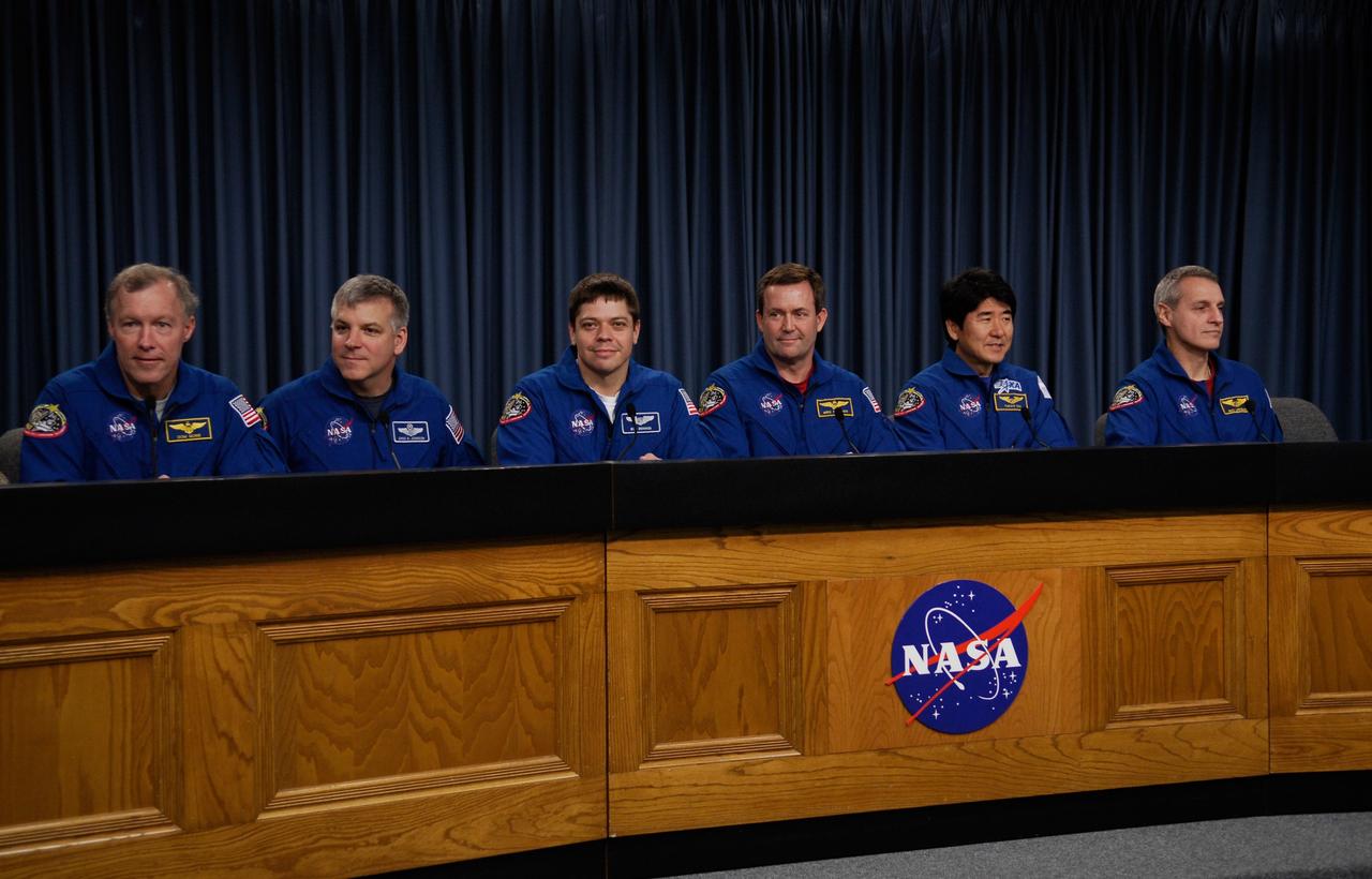
CAPE CANAVERAL, Fla. --- Space shuttle Endeavour crew members meet with the media to discuss their experiences on the STS-123 mission to the International Space Station. From left are Commander Dominic Gorie, Pilot Gregory H. Johnson, and Mission Specialists Robert L. Behnken, Mike Foreman, Japan Aerospace Exploration Agency astronaut Takao Doi and Rick Linnehan. They landed at Kennedy at 8:39 p.m. EDT March 26. Endeavour's 16-day flight was the longest shuttle mission to the International Space Station and included a record five spacewalks. The shuttle's seven astronauts worked with the three-member station crew and ground teams around the world to install the first section of the Japan Aerospace Exploration Agency's Kibo laboratory and the Canadian Space Agency's two-armed robotic system, known as Dextre. Photo credit: NASA/Kim Shiflett
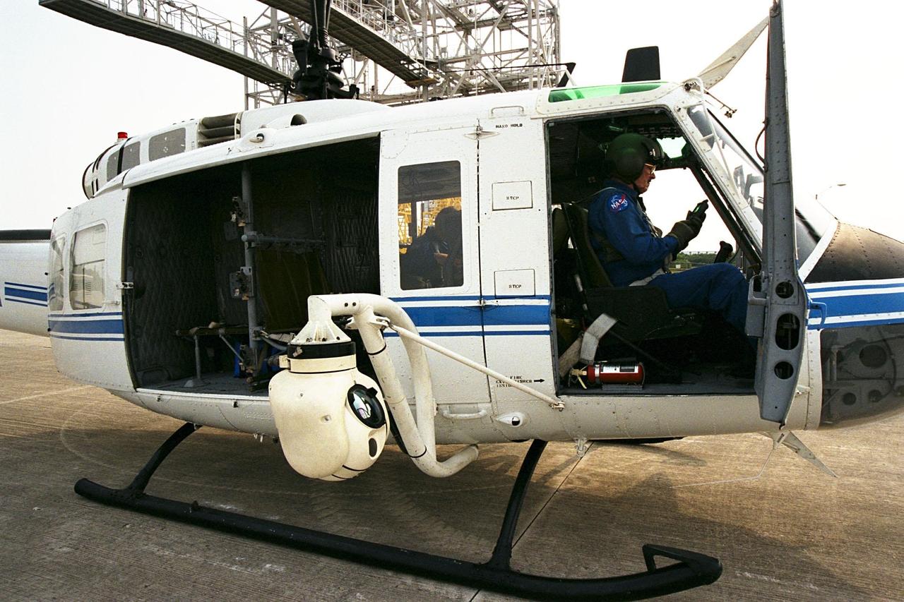
KENNEDY SPACE CENTER, FLA. -- A beach ball-sized infrared camera, part of the Forward Looking Infrared Radar (FLIR), has been mounted on the right siderail of NASA's Huey UH-1 helicopter. A KSC pilot prepares to fly the helicopter, which has also been outfitted with a portable global positioning satellite (GPS) system, to support Florida's Division of Forestry as they fight the brush fires which have been plaguing the state as a result of extremely dry conditions and lightning storms. The FLIR also includes a real-time television monitor and recorder installed inside the helicopter. While the FLIR collects temperature data and images, the GPS system provides the exact coordinates of the fires being observed and transmits the data to the firefighters on the ground. The Kennedy Space Center (KSC) security team routinely uses the FLIR equipment prior to Shuttle launch and landing activities to ensure that the area surrounding the launch pad and runway are clear of unauthorized personnel. KSC's Base Operations Contractor, EG&G Florida, operates the NASA-owned helicopter
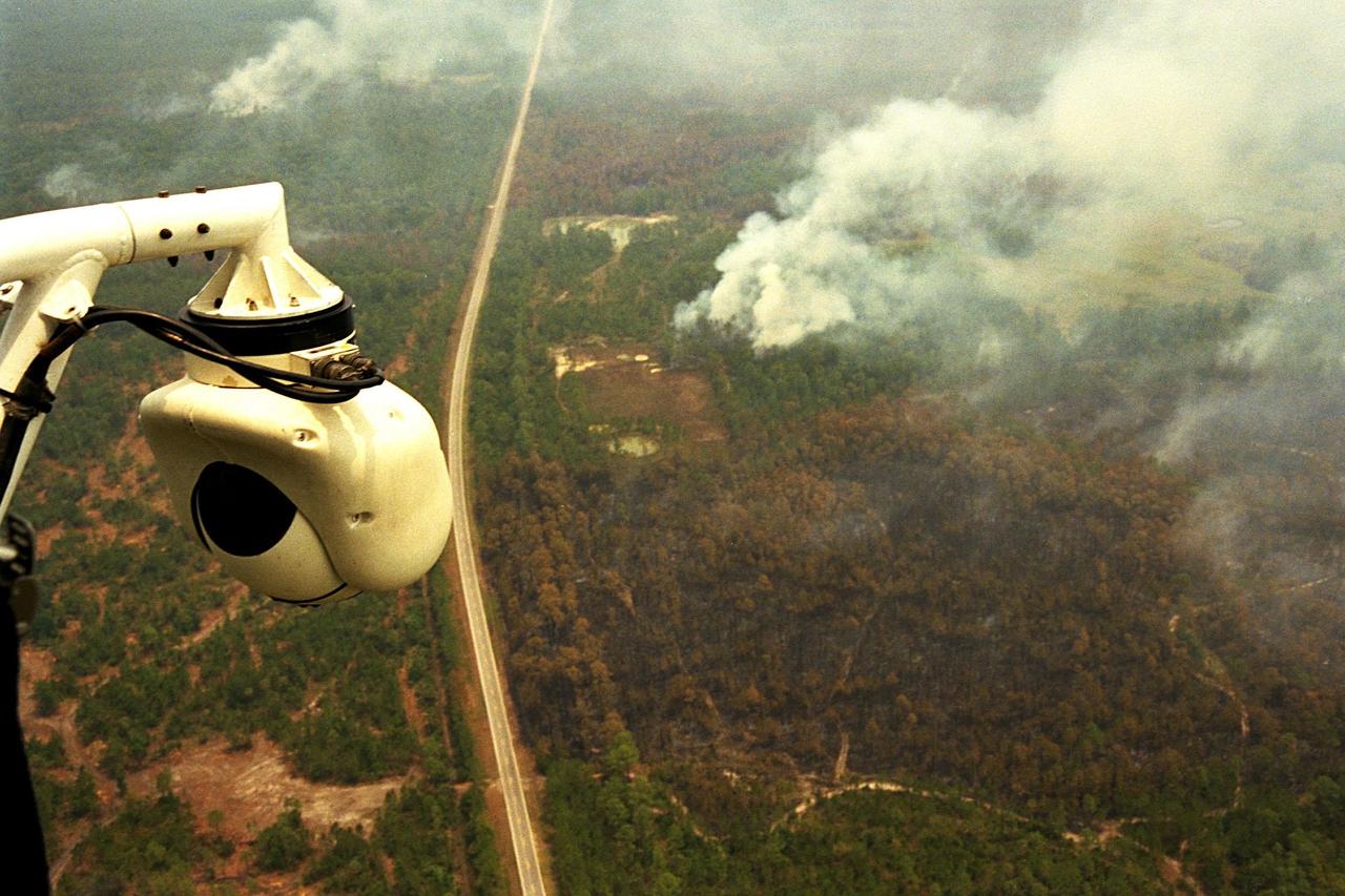
KENNEDY SPACE CENTER, FLA. -- A beach ball-sized infrared camera, part of the Forward Looking Infrared Radar (FLIR), has been mounted on the right siderail of NASA's Huey UH-1 helicopter and is being used to search for fires in Volusia County, Florida. The helicopter has also been outfitted with a portable global positioning satellite (GPS) system to support Florida's Division of Forestry as they fight the brush fires which have been plaguing the state as a result of extremely dry conditions and lightning storms. The FLIR also includes a real-time television monitor and recorder installed inside the helicopter. While the FLIR collects temperature data and images, the GPS system provides the exact coordinates of the fires being observed and transmits the data to the firefighters on the ground. The Kennedy Space Center (KSC) security team routinely uses the FLIR equipment prior to Shuttle launch and landing activities to ensure that the area surrounding the launch pad and runway are clear of unauthorized personnel. KSC's Base Operations Contractor, EG&G Florida, operates the NASA-owned helicopter
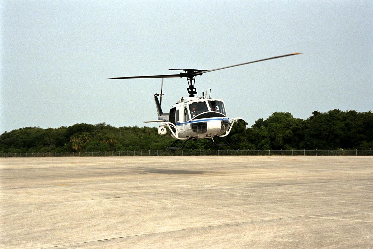
KENNEDY SPACE CENTER, FLA. -- NASA's Huey UH-1 helicopter lands at the Shuttle Landing Facility to pick up Kennedy Space Center (KSC) Security personnel who operate the Forward Looking Infrared Radar (FLIR) installed on board. The helicopter has also been outfitted with a portable global positioning satellite (GPS) system to support Florida's Division of Forestry as they fight the brush fires which have been plaguing the state as a result of extremely dry conditions and lightning storms. The FLIR includes a beach ball-sized infrared camera that is mounted on the helicopter's right siderail and a real-time television monitor and recorder installed inside. While the FLIR collects temperature data and images, the GPS system provides the exact coordinates of the fires being observed and transmits the data to the firefighters on the ground. KSC's security team routinely uses the FLIR equipment prior to Shuttle launch and landing activities to ensure that the area surrounding the launch pad and runway are clear of unauthorized personnel. KSC's Base Operations Contractor, EG&G Florida, operates the NASA-owned helicopter
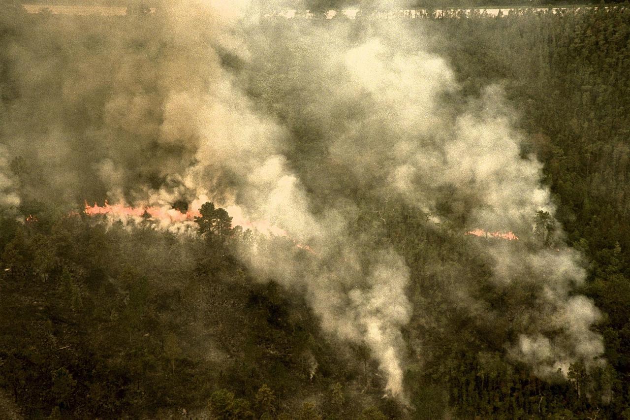
KENNEDY SPACE CENTER, FLA. -- A forest fire burning in Volusia County, Florida, is clearly visible from NASA's Huey UH-1 helicopter. The helicopter has been outfitted with a Forward Looking Infrared Radar (FLIR) and a portable global positioning satellite (GPS) system to support Florida's Division of Forestry as they fight the brush fires which have been plaguing the state as a result of extremely dry conditions and lightning storms. The FLIR includes a beach ball-sized infrared camera that is mounted on the helicopter's right siderail and a real-time television monitor and recorder installed inside. While the FLIR collects temperature data and images, the GPS system provides the exact coordinates of the fires being observed and transmits the data to the firefighters on the ground. The Kennedy Space Center (KSC) security team routinely uses the FLIR equipment prior to Shuttle launch and landing activities to ensure that the area surrounding the launch pad and runway are clear of unauthorized personnel. KSC's Base Operations Contractor, EG&G Florida, operates the NASA-owned helicopter
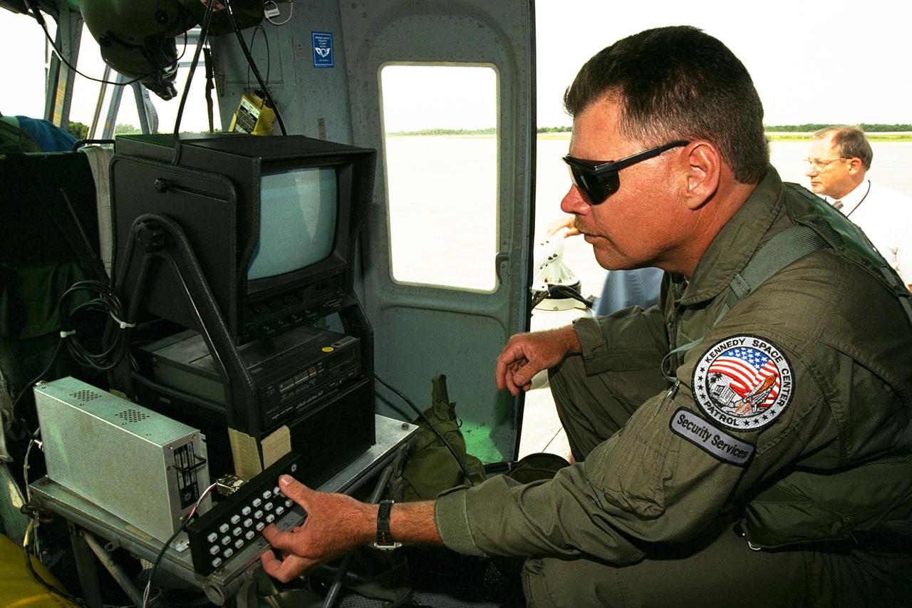
KENNEDY SPACE CENTER, FLA. -- Sgt. Mark Hines, of Kennedy Space Center (KSC) Security, checks out equipment used to operate the Forward Looking Infrared Radar (FLIR) installed on NASA's Huey UH-1 helicopter. The helicopter has also been outfitted with a portable global positioning satellite (GPS) system to support Florida's Division of Forestry as they fight the brush fires which have been plaguing the state as a result of extremely dry conditions and lightning storms. The FLIR includes a beach ball-sized infrared camera that is mounted on the helicopter's right siderail and a real-time television monitor and recorder installed inside. While the FLIR collects temperature data and images, the GPS system provides the exact coordinates of the fires being observed and transmits the data to the firefighters on the ground. KSC's security team routinely uses the FLIR equipment prior to Shuttle launch and landing activities to ensure that the area surrounding the launch pad and runway are clear of unauthorized personnel. KSC's Base Operations Contractor, EG&G Florida, operates the NASA-owned helicopter
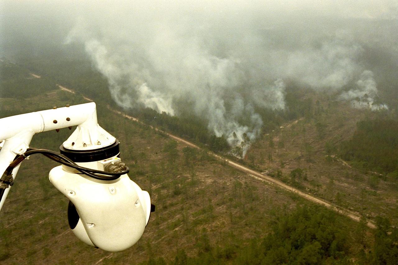
KENNEDY SPACE CENTER, FLA. -- A beach ball-sized infrared camera, part of the Forward Looking Infrared Radar (FLIR), has been mounted on the right siderail of NASA's Huey UH-1 helicopter and is being used to scan a large area of Volusia County, Florida, where a fire burns. The helicopter has also been outfitted with a portable global positioning satellite (GPS) system to support Florida's Division of Forestry as they fight the brush fires which have been plaguing the state as a result of extremely dry conditions and lightning storms. The FLIR also includes a real-time television monitor and recorder installed inside the helicopter. While the FLIR collects temperature data and images, the GPS system provides the exact coordinates of the fires being observed and transmits the data to the firefighters on the ground. The Kennedy Space Center (KSC) security team routinely uses the FLIR equipment prior to Shuttle launch and landing activities to ensure that the area surrounding the launch pad and runway are clear of unauthorized personnel. KSC's Base Operations Contractor, EG&G Florida, operates the NASA-owned helicopter
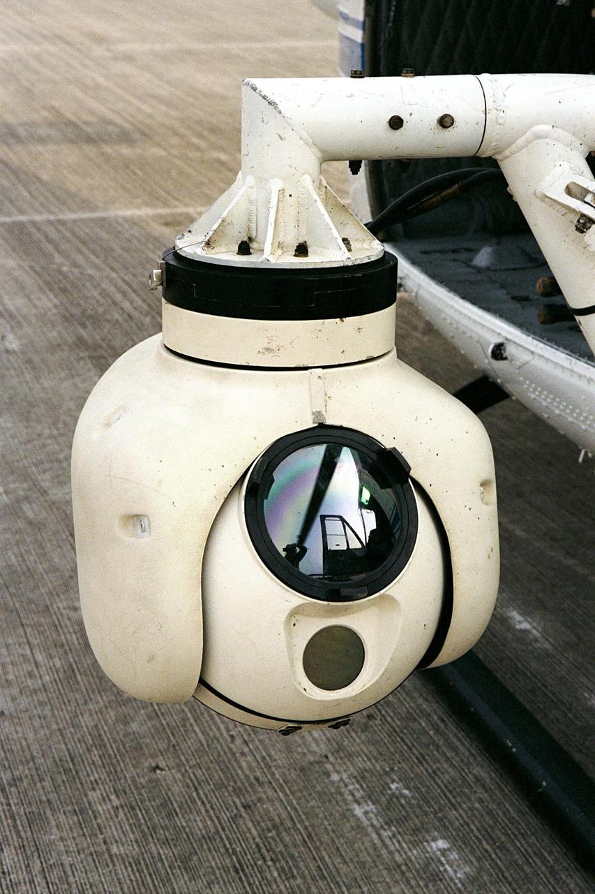
KENNEDY SPACE CENTER, FLA. -- A beach ball-sized infrared camera, part of the Forward Looking Infrared Radar (FLIR), has been mounted on the right siderail of NASA's Huey UH-1 helicopter. The helicopter has also been outfitted with a portable global positioning satellite (GPS) system to support Florida's Division of Forestry as they fight the brush fires which have been plaguing the state as a result of extremely dry conditions and lightning storms. The FLIR also includes a real-time television monitor and recorder installed inside the helicopter. While the FLIR collects temperature data and images, the GPS system provides the exact coordinates of the fires being observed and transmits the data to the firefighters on the ground. The Kennedy Space Center (KSC) security team routinely uses the FLIR equipment prior to Shuttle launch and landing activities to ensure that the area surrounding the launch pad and runway are clear of unauthorized personnel. KSC's Base Operations Contractor, EG&G Florida, operates the NASA-owned helicopter
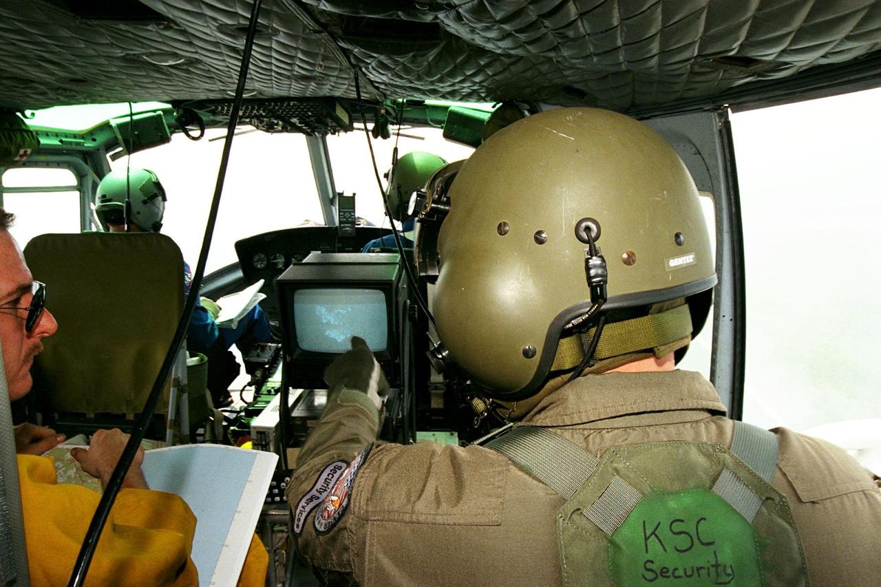
KENNEDY SPACE CENTER, FLA. -- Sgt. Mark Hines, of Kennedy Space Center (KSC) Security, points out a view of a fire on the Forward Looking Infrared Radar (FLIR) video screen to Greg Dunn, of Florida's Division of Forestry, as KSC pilots fly NASA's Huey UH-1 helicopter over fires burning in Volusia County, Florida. The FLIR includes a beach-ball sized infrared camera that is mounted on the helicopter's right siderail and a real-time TV monitor and recorder installed inside. The helicopter has also been outfitted with a portable global positioning satellite (GPS) system to support the Division of Forestry as they fight the brush fires which have been plaguing the state as a result of extremely dry conditions and lightning storms. While the FLIR collects temperature data and images, the GPS system provides the exact coordinates of the fires being observed and transmits the data to the firefighters on the ground. KSC's security team routinely uses the FLIR equipment prior to Shuttle launch and landing activities to ensure that the area surrounding the launch pad and runway are clear of unauthorized personnel. KSC's Base Operations Contractor, EG&G Florida, operates the NASA-owned helicopter.
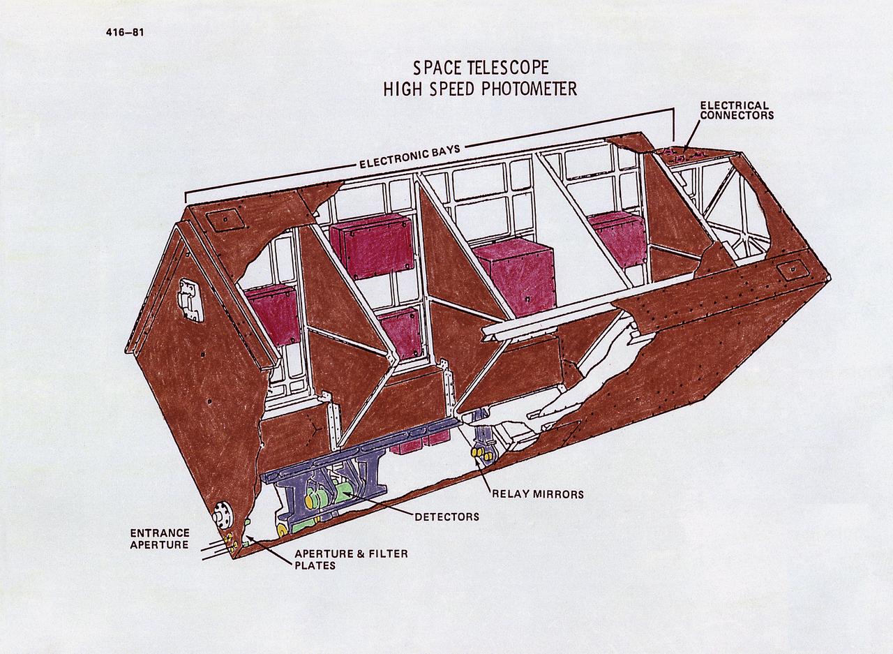
This drawing illustrates the Hubble Space Telescope's (HST's) High Speed Photometer (HSP). The HSP measures the intensity of starlight (brightness), which will help determine astronomical distances. Its principal use will be to measure extremely-rapid variations or pulses in light from celestial objects, such as pulsating stars. The HSP produces brightness readings. Light passes into one of four special signal-multiplying tubes that record the data. The HSP can measure energy fluctuations from objects that pulsate as rapidly as once every 10 microseconds. From HSP data, astronomers expect to learn much about such mysterious objects as pulsars, black holes, and quasars. The purpose of the HST, the most complex and sensitive optical telescope ever made, is to study the cosmos from a low-Earth orbit. By placing the telescope in space, astronomers are able to collect data that is free of the Earth's atmosphere. The HST views galaxies, stars, planets, comets, possibly other solar systems, and even unusual phenomena such as quasars, with 10 times the clarity of ground-based telescopes. The HST was deployed from the Space Shuttle Discovery (STS-31 mission) into Earth orbit in April 1990. The Marshall Space Flight Center had responsibility for design, development, and construction of the HST. The Perkin-Elmer Corporation, in Danbury, Cornecticut, developed the optical system and guidance sensors.
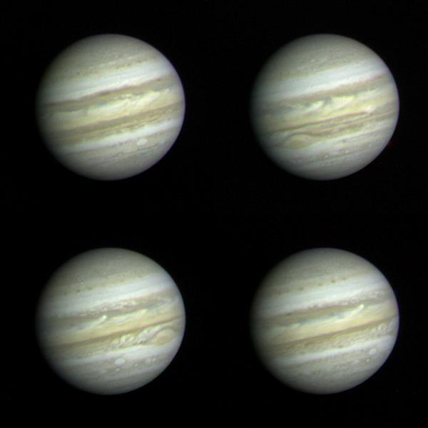
These Jupiter photographs are part of a set taken by NASA Voyager 1 on December 10 and 11, 1978 from a distance of 83 million km 52 million miles or more than half the distance from the Earth to the sun. At this range, Voyager 1 is able to record more detail on the giant planet than the very best ground-based telescopes. The highest resolution ever obtained on the Jovian disk was recorded by Pioneer 11 four years ago. Voyager, however, has longer focal-length optics than Pioneer, and while nearly three months from encounter (~ March 1979) was able to achieve higher resolution than that obtained by Pioneer only 24 hours from its encounter on 3 December 1974. Jupiter's colorful and turbulent atmosphere is evident in these photographs. The entire visible surface of the planet is made up of multiple layers of clouds, composed primarily of ammonia ice crystals colored by small amounts of materials of unknown composition. The Great Red Spot, seen to the lower left of 2 and lower right of 3, is now recovering from a period of relative inconspicuousness. An atmospheric system larger than the Earth and more than 100 years old, the Great Red Spot remains a mystery and a challenge to Voyager instruments. A bright convective cloud (center of and right of center in 4) displays a plume which has been swept westward (to the left) by local currents in the planet's equatorial wind system. Below and to the left and right of the Great Red Spot are a pair of white oval clouds; a third can be seen in 1. All three were formed almost 40 years ago and are the second oldest class of discrete features identified in the Jovian atmosphere. Each of the pictures was produced from blue, green, and orange originals in JPL's Image Processing Laboratory. http://photojournal.jpl.nasa.gov/catalog/PIA00454
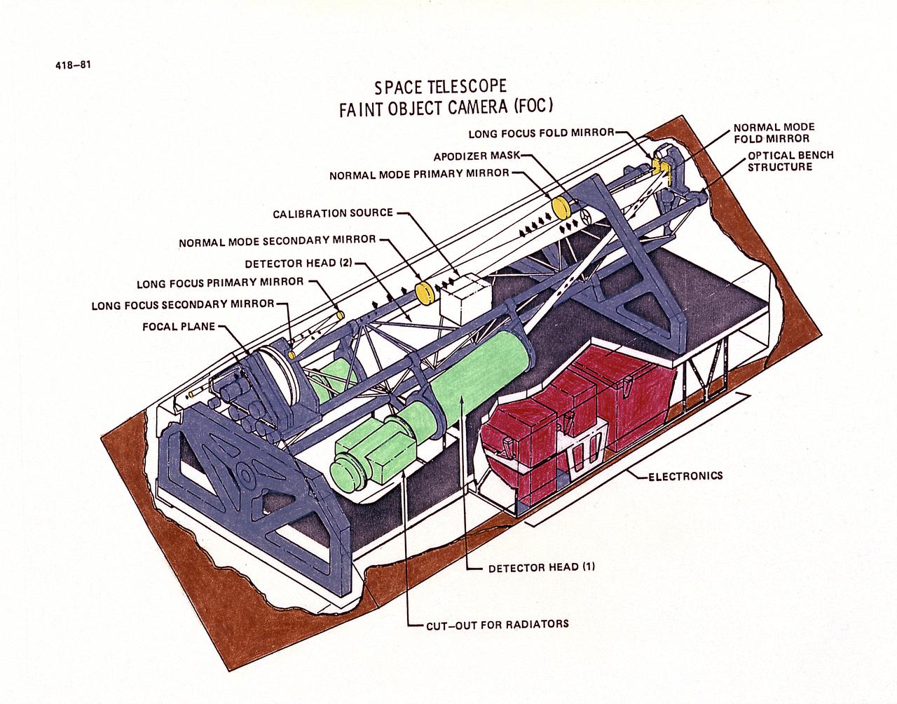
This drawing illustrates Hubble Space Telescope's (HST's), Faint Object Camera (FOC). The FOC reflects light down one of two optical pathways. The light enters a detector after passing through filters or through devices that can block out light from bright objects. Light from bright objects is blocked out to enable the FOC to see background images. The detector intensifies the image, then records it much like a television camera. For faint objects, images can be built up over long exposure times. The total image is translated into digital data, transmitted to Earth, and then reconstructed. The purpose of the HST, the most complex and sensitive optical telescope ever made, is to study the cosmos from a low-Earth orbit. By placing the telescope in space, astronomers are able to collect data that is free of the Earth's atmosphere. The HST detects objects 25 times fainter than the dimmest objects seen from Earth and provides astronomers with an observable universe 250 times larger than visible from ground-based telescopes, perhaps as far away as 14 billion light-years. The HST views galaxies, stars, planets, comets, possibly other solar systems, and even unusual phenomena such as quasars, with 10 times the clarity of ground-based telescopes. The HST was deployed from the Space Shuttle Discovery (STS-31 mission) into Earth orbit in April 1990. The Marshall Space Flight Center had responsibility for design, development, and construction of the HST. The Perkin-Elmer Corporation, in Danbury, Cornecticut, developed the optical system and guidance sensors.
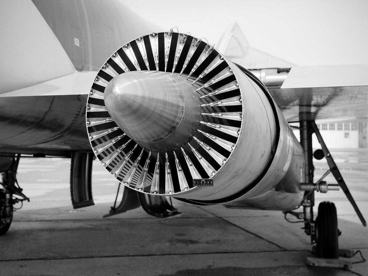
National Aeronautics and Space Administration (NASA) Convair F-106B Delta Dart with a 32-spoke nozzle installed on its General Electric J85 test engine. Lewis acquired a Delta Dart fighter in 1966 to study the components for propulsion systems that could be applied to supersonic transport aircraft at transonic speeds. The F-106B was modified with two General Electric J85-13 engines under its wings to study these components. The original test plan was expanded to include the study of boattail drag, noise reduction, and inlets. From February to July 1971 the modified F-106B was used to study different ejector nozzles. Researchers conducted both acoustic and aerodynamic tests on the ground and in flight. Several models were created to test different suppression methods. NASA Lewis’ conical nozzle was used as the baseline configuration. Flightline and sideline microphones were set up on the ground. The F-106B would idle its own engine and buzz the recording station from an altitude of 300 feet at Mach 0.4 with the test engines firing. Researchers found that the suppression of the perceived noise level was usually lower during flight than the researchers had statistically predicted. The 64 and 32-spoke nozzles performed well in actual flight, but the others nozzles tended to negatively affect the engine’s performance. Different speeds or angles- -of-attack sometimes changed the noise levels. In the end, no general conclusions could be applied to all the nozzles.
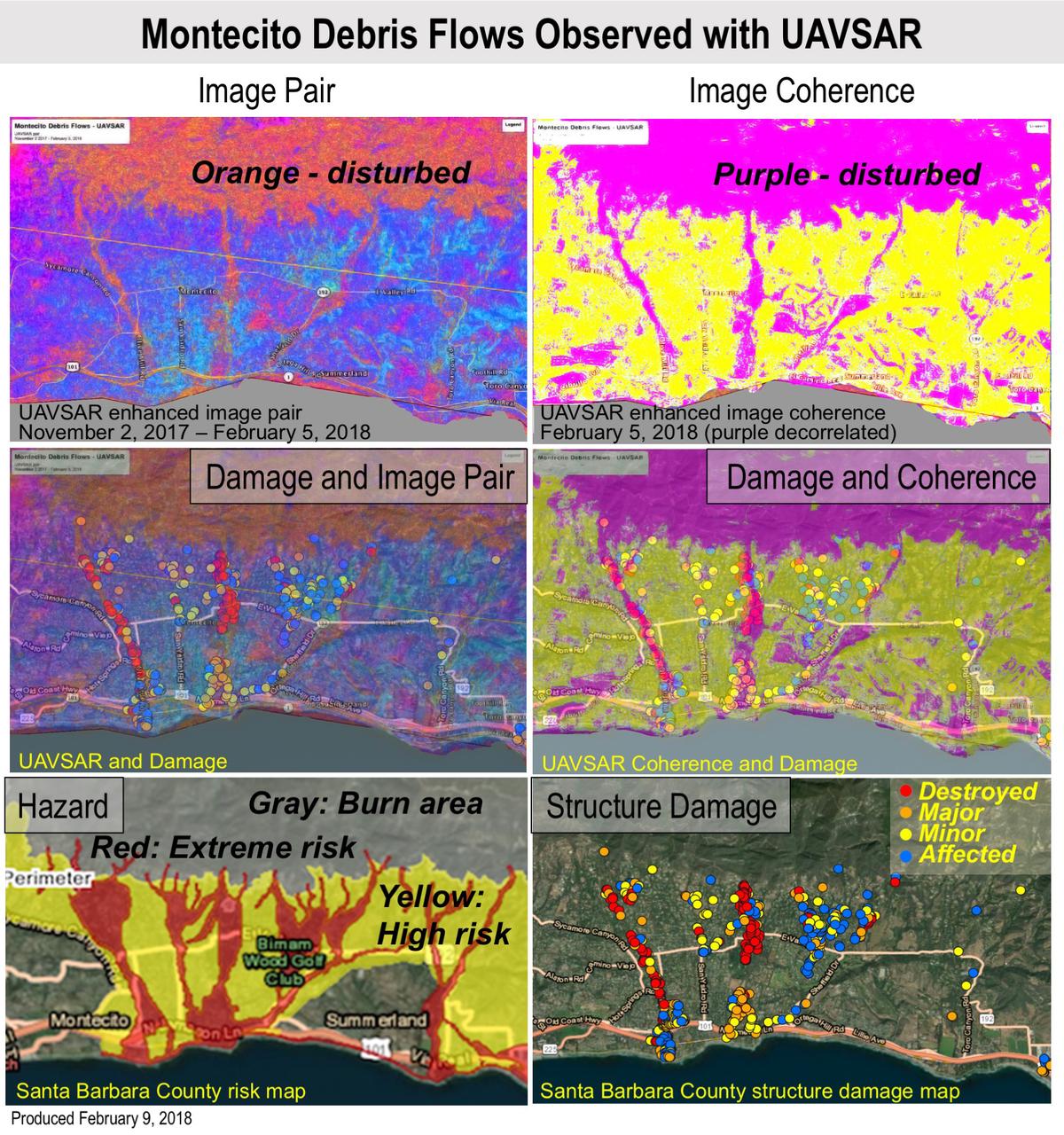
Extreme winter rains in January 2018 following the Thomas Fire in Ventura and Santa Barbara Counties caused severe debris flows, resulting in significant loss of life and considerable property damage in the town on Montecito, just east of Santa Barbara. NASA's Uninhabited Aerial Vehicle Synthetic Aperture Radar (UAVSAR) airborne radar platform detected changes caused by the debris flows between two images acquired on Nov. 2, 2017, and Feb. 5, 2018. An enhanced image pair (top left) shows disturbed areas in orange. In areas of severe surface disruption from the fire scar and debris flows the two image pairs can't be matched and decorrelate (top right). In the middle panels, the radar images are overlaid on the structure damage map produced by the County of Santa Barbara. The fire scars and damage correspond well with the risk map (lower left) and damage map (lower right). With an operational system, products such as these have the potential to augment information available for search and rescue, and for damage assessment for government agencies or the insurance industry. Radar has the advantage of being available in all weather conditions, as it can image through clouds. NASA's Uninhabited Aerial Vehicle Synthetic Aperture Radar (UAVSAR), developed and managed by the Jet Propulsion Laboratory, Pasadena, California, can record changes on the ground beneath the aircraft that occur between multiple flights, which take exactly the same flight path. The instrument is used to monitor how volcanoes, earthquakes, and other natural hazards are changing Earth. The JPL UAVSAR team collected and processed the imagery for Principal Investigator Andrea Donnellan who performed the analysis. She has been conducting ground change research using UAVSAR in this and other regions of California since 2009. https://photojournal.jpl.nasa.gov/catalog/PIA22243
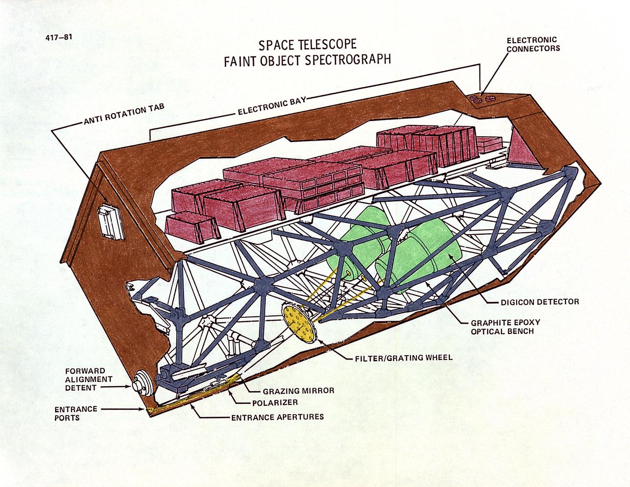
This drawing illustrates the Hubble Space Telescope's (HST's), Faint Object Spectrograph (FOS). The HST's two spectrographs, the Goddard High-Resolution Spectrograph and the FOS, can detect a broader range of wavelengths than is possible from the Earth because there is no atmosphere to absorb certain wavelengths. Scientists can determine the chemical composition, temperature, pressure, and turbulence of the stellar atmosphere producing the light, all from spectral data. The FOC can detect detail in very faint objects, such as those at great distances, and light ranging from ultraviolet to red spectral bands. Both spectrographs operate in essentially the same way. The incoming light passes through a small entrance aperture, then passes through filters and diffraction gratings, that work like prisms. The filter or grating used determines what range of wavelength will be examined and in what detail. Then the spectrograph detectors record the strength of each wavelength band and sends it back to Earth. The purpose of the HST, the most complex and sensitive optical telescope ever made, is to study the cosmos from a low-Earth orbit. By placing the telescope in space, astronomers are able to collect data that is free of the Earth's atmosphere. The HST views galaxies, stars, planets, comets, possibly other solar systems, and even unusual phenomena such as quasars, with 10 times the clarity of ground-based telescopes. The HST was deployed from the Space Shuttle Discovery (STS-31 mission) into Earth orbit in April 1990. The Marshall Space Flight Center had responsibility for design, development, and construction of the HST. The Perkin-Elmer Corporation, in Danbury, Cornecticut, developed the optical system and guidance sensors.
NASA image release May 11, 2010 Hubble Catches Heavyweight Runaway Star Speeding from 30 Doradus Image: Hubble/WFPC2 and ESO/2.2-m Composite Image of 30 Dor Runaway Star A blue-hot star, 90 times more massive than our Sun, is hurtling across space fast enough to make a round trip from Earth to the Moon in merely two hours. Though the speed is not a record-breaker, it is unique to find a homeless star that has traveled so far from its nest. The only way the star could have been ejected from the star cluster where it was born is through a tussle with a rogue star that entered the binary system where the star lived, which ejected the star through a dynamical game of stellar pinball. This is strong circumstantial evidence for stars as massive as 150 times our Sun's mass living in the cluster. Only a very massive star would have the gravitational energy to eject something weighing 90 solar masses. The runaway star is on the outskirts of the 30 Doradus nebula, a raucous stellar breeding ground in the nearby Large Magellanic Cloud. The finding bolsters evidence that the most massive stars in the local universe reside in 30 Doradus, making it a unique laboratory for studying heavyweight stars. 30 Doradus, also called the Tarantula Nebula, is roughly 170,000 light-years from Earth. To learn more about this image go to: <a href="http://www.nasa.gov/mission_pages/hubble/science/runaway-star.html" rel="nofollow">www.nasa.gov/mission_pages/hubble/science/runaway-star.html</a> Credit: NASA, ESA, J. Walsh (ST-ECF), and ESO <b><a href="http://www.nasa.gov/centers/goddard/home/index.html" rel="nofollow">NASA Goddard Space Flight Center</a></b> is home to the nation's largest organization of combined scientists, engineers and technologists that build spacecraft, instruments and new technology to study the Earth, the sun, our solar system, and the universe.
The IML-1 mission was the first in a series of Shuttle flights dedicated to fundamental materials and life sciences research with the international partners. The participating space agencies included: NASA, the 14-nation European Space Agency (ESA), the Canadian Space Agency (CSA), The French National Center of Space Studies (CNES), the German Space Agency and the German Aerospace Research Establishment (DAR/DLR), and the National Space Development Agency of Japan (NASDA). Dedicated to the study of life and materials sciences in microgravity, the IML missions explored how life forms adapt to weightlessness and investigated how materials behave when processed in space. Both life and materials sciences benefited from the extended periods of microgravity available inside the Spacelab science module in the cargo bay of the Space Shuttle Orbiter. This photograph shows Astronaut Norman Thagard performing the fluid experiment at the Fluid Experiment System (FES) facility inside the laboratory module. The FES facility had sophisticated optical systems for imaging fluid flows during materials processing, such as experiments to grow crystals from solution and solidify metal-modeling salts. A special laser diagnostic technique recorded the experiments, holograms were made for post-flight analysis, and video was used to view the samples in space and on the ground. Managed by the Marshall Space Flight Center (MSFC), the IML-1 mission was launched on January 22, 1992 aboard the Shuttle Orbiter Discovery (STS-42).

NASA image release May 11, 2010 Hubble Catches Heavyweight Runaway Star Speeding from 30 Doradus Image: ESO 2.2-m WFI Image of the Tarantula Nebula A blue-hot star, 90 times more massive than our Sun, is hurtling across space fast enough to make a round trip from Earth to the Moon in merely two hours. Though the speed is not a record-breaker, it is unique to find a homeless star that has traveled so far from its nest. The only way the star could have been ejected from the star cluster where it was born is through a tussle with a rogue star that entered the binary system where the star lived, which ejected the star through a dynamical game of stellar pinball. This is strong circumstantial evidence for stars as massive as 150 times our Sun's mass living in the cluster. Only a very massive star would have the gravitational energy to eject something weighing 90 solar masses. The runaway star is on the outskirts of the 30 Doradus nebula, a raucous stellar breeding ground in the nearby Large Magellanic Cloud. The finding bolsters evidence that the most massive stars in the local universe reside in 30 Doradus, making it a unique laboratory for studying heavyweight stars. 30 Doradus, also called the Tarantula Nebula, is roughly 170,000 light-years from Earth. To learn more about this image go to: <a href="http://www.nasa.gov/mission_pages/hubble/science/runaway-star.html" rel="nofollow">www.nasa.gov/mission_pages/hubble/science/runaway-star.html</a> Credit: NASA/ESO, J. Alves (Calar Alto, Spain), and B. Vandame and Y. Beletski (ESO) <b><a href="http://www.nasa.gov/centers/goddard/home/index.html" rel="nofollow">NASA Goddard Space Flight Center</a></b> is home to the nation's largest organization of combined scientists, engineers and technologists that build spacecraft, instruments and new technology to study the Earth, the sun, our solar system, and the universe.
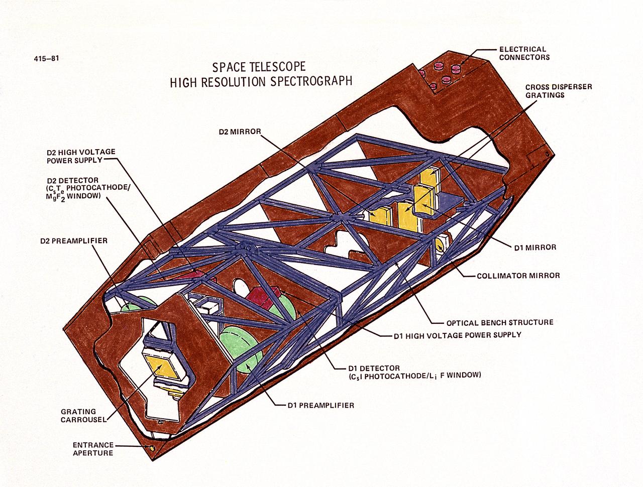
This drawing illustrates the Hubble Space Telescope's (HST's), Goddard High-Resolution Spectrograph (GHRS). The HST's two spectrographs, the GHRS and the Faint Object Spectrograph (FOS), can detect a broader range of wavelengths than is possible from Earth because there is no atmosphere to absorb certain wavelengths. Scientists can determine the chemical composition, temperature, pressure, and turbulence of the stellar atmosphere producing the light, all from spectral data. The GHRS can detect fine details in the light from somewhat brighter objects but only ultraviolet light. Both spectrographs operate in essentially the same way. The incoming light passes through a small entrance aperture, then passes through filters and diffraction gratings, that work like prisms. The filter or grating used determines what range of wavelength will be examined and in what detail. Then the spectrograph detectors record the strength of each wavelength band and sends it back to Earth. The purpose of the HST, the most complex and sensitive optical telescope ever made, is to study the cosmos from a low-Earth orbit. By placing the telescope in space, astronomers are able to collect data that is free of the Earth's atmosphere. The HST views galaxies, stars, planets, comets, possibly other solar systems, and even unusual phenomena such as quasars, with 10 times the clarity of ground-based telescopes. The HST was deployed from the Space Shuttle Discovery (STS-31 mission) into Earth orbit in April 1990. The Marshall Space Flight Center had responsibility for design, development, and construction of the HST. The Perkin-Elmer Corporation, in Danbury, Cornecticut, developed the optical system and guidance sensors.
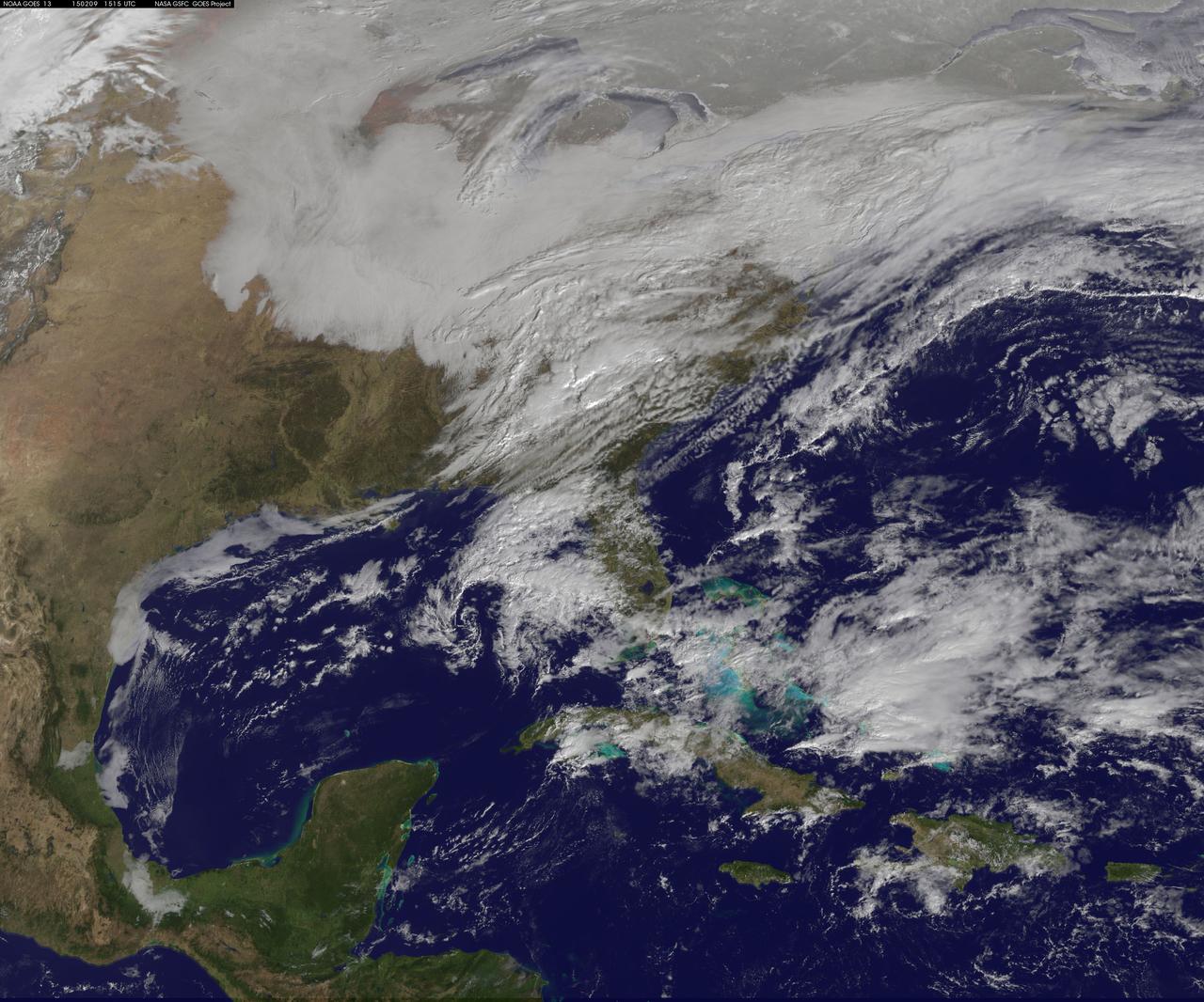
Another large snowstorm affecting New England was dropping more snow on the region and breaking records on February 9, as NOAA's GOES-East satellite captured an image of the clouds associated with the storm system. On Feb. 9, NOAA's National Weather Service in Boston, Massachusetts noted that "The 30-day snowfall total at Boston ending 7 a.m. this morning is 61.6 inches. This exceeds the previous maximum 30 day snowfall total on record at Boston, which was 58.8 inches ending Feb 7 1978." The GOES-East image was created by NASA/NOAA's GOES Project at NASA's Goddard Space Flight Center in Greenbelt, Maryland. It showed a blanket of clouds over the U.S. northeast that stretched down to the Mid-Atlantic where there was no snow on the ground in Washington, D.C. NOAA's National Weather Service Weather Prediction Center provided a look at the extent of the storm system and noted "Heavy snow will impact portions of New York State and New England as the new week begins. Freezing rain will spread from western Pennsylvania to Long Island, with rain for the mid-Atlantic states." The low pressure area bringing the snow to the northeast was located in central Pennsylvania. A cold front extended southward from the low across the Tennessee Valley while a stationary boundary extended eastward from the low across the central mid-Atlantic. To create the image, NASA/NOAA's GOES Project takes the cloud data from NOAA's GOES-East satellite and overlays it on a true-color image of land and ocean created by data from the Moderate Resolution Imaging Spectroradiometer, or MODIS, instrument that flies aboard NASA's Aqua and Terra satellites. Together, those data created the entire picture of the storm. NOAA's GOES satellites provide the kind of continuous monitoring necessary for intensive data analysis. Geostationary describes an orbit in which a satellite is always in the same position with respect to the rotating Earth. This allows GOES to hover continuously over one position on Earth's surface, appearing stationary. As a result, GOES provide a constant vigil for the atmospheric triggers for severe weather conditions such as tornadoes, flash floods, hail storms and hurricanes. For updated information about the storm system, visit NOAA's NWS website: <a href="http://www.weather.gov" rel="nofollow">www.weather.gov</a> For more information about GOES satellites, visit: <a href="http://www.goes.noaa.gov/" rel="nofollow">www.goes.noaa.gov/</a> or goes.gsfc.nasa.gov/ Rob Gutro NASA's Goddard Space Flight Center <b><a href="http://goes.gsfc.nasa.gov/" rel="nofollow">Credit: NOAA/NASA GOES Project</a></b> <b><a href="http://www.nasa.gov/audience/formedia/features/MP_Photo_Guidelines.html" rel="nofollow">NASA image use policy.</a></b> <b><a href="http://www.nasa.gov/centers/goddard/home/index.html" rel="nofollow">NASA Goddard Space Flight Center</a></b> enables NASA’s mission through four scientific endeavors: Earth Science, Heliophysics, Solar System Exploration, and Astrophysics. Goddard plays a leading role in NASA’s accomplishments by contributing compelling scientific knowledge to advance the Agency’s mission. <b>Follow us on <a href="http://twitter.com/NASAGoddardPix" rel="nofollow">Twitter</a></b> <b>Like us on <a href="http://www.facebook.com/pages/Greenbelt-MD/NASA-Goddard/395013845897?ref=tsd" rel="nofollow">Facebook</a></b> <b>Find us on <a href="http://instagram.com/nasagoddard?vm=grid" rel="nofollow">Instagram</a></b>

This graph presents measured properties of the seven TRAPPIST-1 exoplanets (labeled b through h), showing how they stack up with one another as well as with Earth and the other inner rocky worlds in our own solar system. The relative sizes of the planets are indicated by the circles. All of the known TRAPPIST-1 planets are larger than Mars, with five of them within 15% of the diameter of Earth. The vertical axis shows the uncompressed densities of the planets. Density, calculated from a planet's mass and volume, is the first important step in understanding its composition. Uncompressed density takes into account that the larger a planet is, the more its own gravity will pack the planet's material together and increase its density. Uncompressed density, therefore, usually provides a better means of comparing the composition of planets. The plot shows that the uncompressed densities of the TRAPPIST-1 planets are similar to one another, suggesting they may have all have a similar composition. The four rocky planets in our own solar system show more variation in density compared to the seven TRAPPIST-1 planets. Mercury, for example, contains a much higher percentage of iron than the other three rocky planets and thus has a much higher uncompressed density. The horizontal axis shows the level of illumination that each planet receives from its host star. The TRAPPIST-1 star is a mere 9% the mass of our Sun, and its temperature is much cooler. But because the TRAPPIST-1 planets orbit so closely to their star, they receive comparable levels of light and heat to Earth and its neighboring planets. The corresponding "habitable zones" — regions where an Earth-like planet could potentially support liquid water on its surface — of the two planetary systems are indicated near the top of the plot. The the two zones do not line up exactly because the cooler TRAPPIST-1 star emitting more of its light in the form of infrared radiation that is more efficiently absorbed by an Earth-like atmosphere. Since it takes less illumination to reach the same temperatures, the habitable zone shifts farther away from the star. The masses and densities of the TRAPPIST-1 planets were determined by measurements of slight variations in the timings of their orbits using extensive observations made by NASA's Spitzer and Kepler space telescopes, in combination with data from Hubble and a number of ground-based telescopes. The latest analysis, which includes Spitzer's complete record of over 1,000 hours of TRAPPIST-1 observations, has reduced the uncertainties of the mass measurements to a mere 3-6%. These are among the most accurate measurements of planetary masses anywhere outside of our solar system. https://photojournal.jpl.nasa.gov/catalog/PIA24371
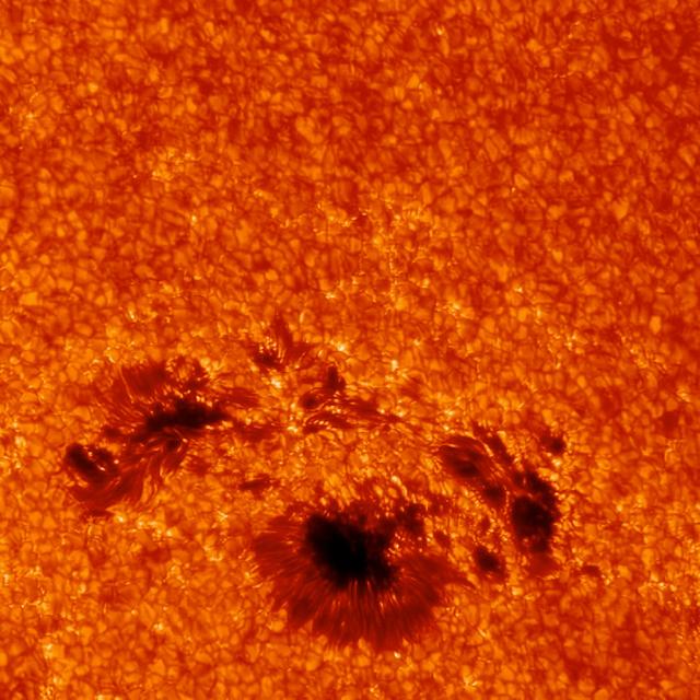
This close-up of the sunspot underneath the March 29, 2014, flare shows incredible detail. The image was captured by the G-band camera at Sacramento Peak in New Mexico. This instrument can focus on only a small area at once, but provide very high resolution. Ground-based telescope data can be hindered by Earth's atmosphere, which blocks much of the sun's ultraviolet and X-ray light, and causes twinkling even in the light it does allow through. As it happens, the March 29 flare occurred at a time of day in New Mexico that often results in the best viewing times from the ground. Credit: Kevin Reardon (National Solar Observatory), Lucia Kleint (BAER Institute) -- On March 29, 2014 the sun released an X-class flare. It was observed by NASA's Interface Region Imaging Spectrograph, or IRIS; NASA's Solar Dynamics Observatory, or SDO; NASA's Reuven Ramaty High Energy Solar Spectroscopic Imager, or RHESSI; the Japanese Aerospace Exploration Agency's Hinode; and the National Solar Observatory's Dunn Solar Telescope located at Sacramento Peak in New Mexico. To have a record of such an intense flare from so many observatories is unprecedented. Such research can help scientists better understand what catalyst sets off these large explosions on the sun. Perhaps we may even some day be able to predict their onset and forewarn of the radio blackouts solar flares can cause near Earth - blackouts that can interfere with airplane, ship and military communications. Read more: <a href="http://1.usa.gov/1kMDQbO" rel="nofollow">1.usa.gov/1kMDQbO</a> Join our Google+ Hangout on May 8 at 2:30pm EST: <a href="http://go.nasa.gov/1mwbBEZ" rel="nofollow">go.nasa.gov/1mwbBEZ</a> Credit: NASA Goddard <b><a href="http://www.nasa.gov/audience/formedia/features/MP_Photo_Guidelines.html" rel="nofollow">NASA image use policy.</a></b> <b><a href="http://www.nasa.gov/centers/goddard/home/index.html" rel="nofollow">NASA Goddard Space Flight Center</a></b> enables NASA’s mission through four scientific endeavors: Earth Science, Heliophysics, Solar System Exploration, and Astrophysics. Goddard plays a leading role in NASA’s accomplishments by contributing compelling scientific knowledge to advance the Agency’s mission. <b>Follow us on <a href="http://twitter.com/NASAGoddardPix" rel="nofollow">Twitter</a></b> <b>Like us on <a href="http://www.facebook.com/pages/Greenbelt-MD/NASA-Goddard/395013845897?ref=tsd" rel="nofollow">Facebook</a></b> <b>Find us on <a href="http://instagram.com/nasagoddard?vm=grid" rel="nofollow">Instagram</a></b>
NASA test pilot Nils Larson walks around an F-15B research aircraft for a rehearsal flight supporting the agency’s Quesst mission at NASA’s Armstrong Flight Research Center in Edwards, California. The flight was part of a full-scale dress rehearsal for Phase 2 of the mission, which will eventually measure quiet sonic thumps generated by the X-59. The flight series helped NASA teams refine procedures and practice data collection ahead of future X-59 flights.
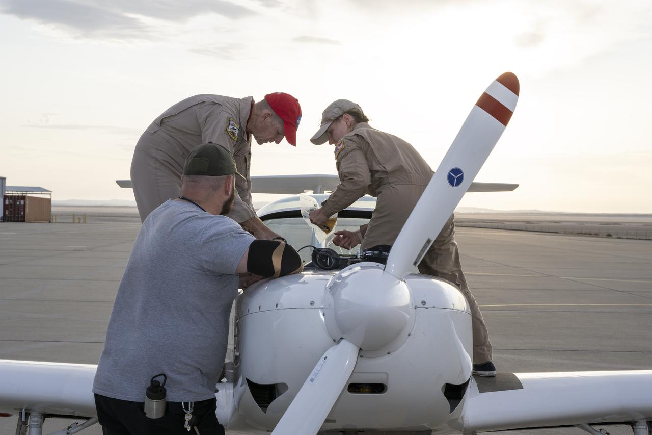
A NASA TG-14 glider aircraft is prepared for flight at NASA’s Armstrong Flight Research Center in Edwards, California, in support of the agency’s Quesst mission. The aircraft is equipped with onboard microphones to capture sonic boom noise generated during rehearsal flights, helping researchers measure the acoustic signature of supersonic aircraft closer to the ground.
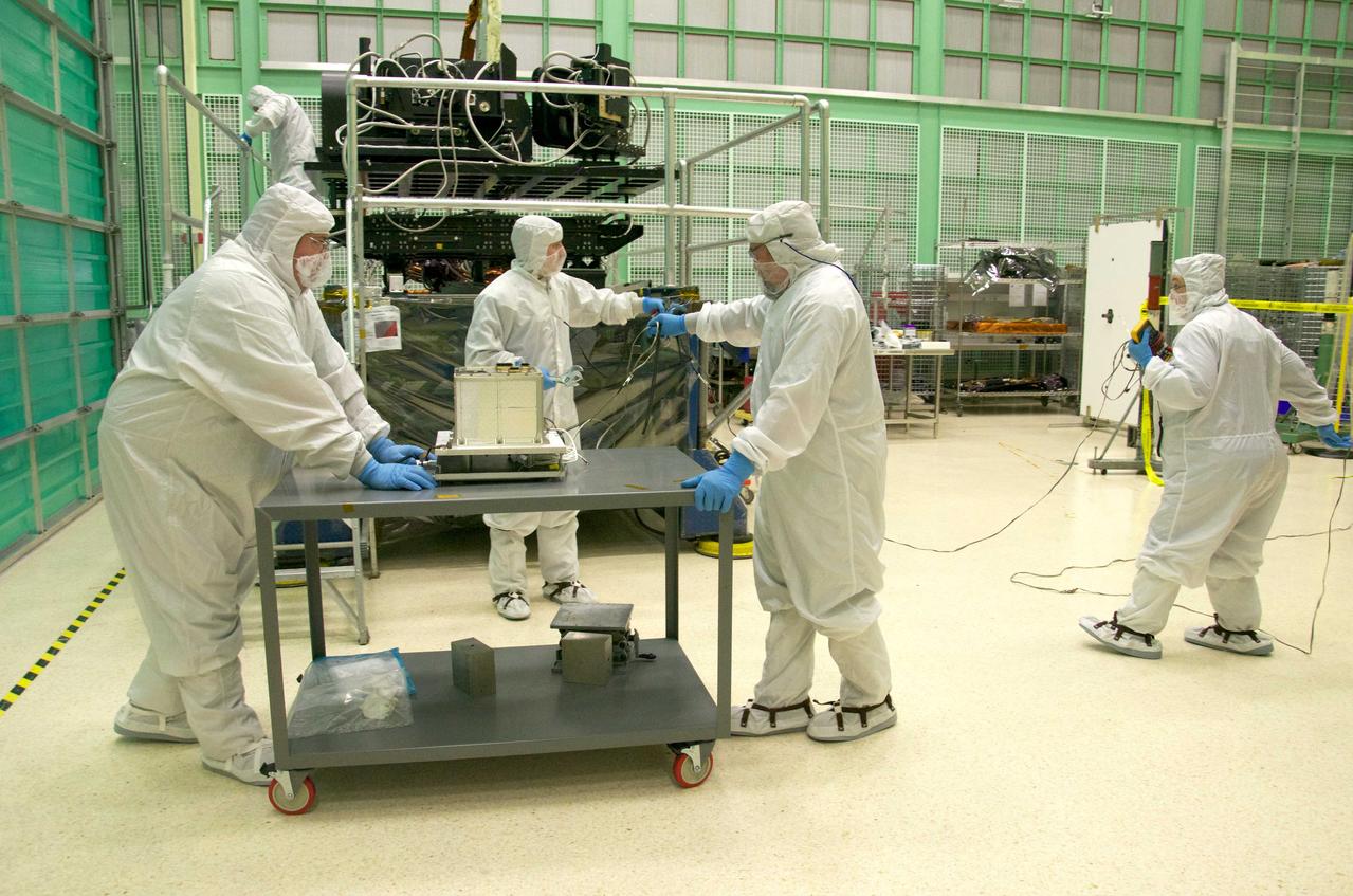
Pete Steigner, and Mike Golob (middle and right) assist an Chris Kolos in carefully moving a TIRS component across the clean room at Goddard. On the far right Robin Knight holds the component's 'grounding strap.' It's used to make sure that any static electricity that could possibly build up while the component is being moved doesn't affect the damage the sensitive electronics. The Thermal Infrared Sensor (TIRS) will fly on the next Landsat satellite, the Landsat Data Continuity Mission (LDCM). TIRS was built on an accelerated schedule at NASA's Goddard Space Flight Center, Greenbelt, Md. and will now be integrated into the LDCM spacecraft at Orbital Science Corp. in Gilbert, Ariz. The Landsat Program is a series of Earth observing satellite missions jointly managed by NASA and the U.S. Geological Survey. Landsat satellites have been consistently gathering data about our planet since 1972. They continue to improve and expand this unparalleled record of Earth's changing landscapes for the benefit of all. For more information on Landsat, visit: <a href="http://www.nasa.gov/landsat" rel="nofollow">www.nasa.gov/landsat</a> Credit: NASA/GSFC/Rebecca Roth <b><a href="http://www.nasa.gov/audience/formedia/features/MP_Photo_Guidelines.html" rel="nofollow">NASA image use policy.</a></b> <b><a href="http://www.nasa.gov/centers/goddard/home/index.html" rel="nofollow">NASA Goddard Space Flight Center</a></b> enables NASA’s mission through four scientific endeavors: Earth Science, Heliophysics, Solar System Exploration, and Astrophysics. Goddard plays a leading role in NASA’s accomplishments by contributing compelling scientific knowledge to advance the Agency’s mission. <b>Follow us on <a href="http://twitter.com/NASA_GoddardPix" rel="nofollow">Twitter</a></b> <b>Like us on <a href="http://www.facebook.com/pages/Greenbelt-MD/NASA-Goddard/395013845897?ref=tsd" rel="nofollow">Facebook</a></b> <b>Find us on <a href="http://instagrid.me/nasagoddard/?vm=grid" rel="nofollow">Instagram</a></b>
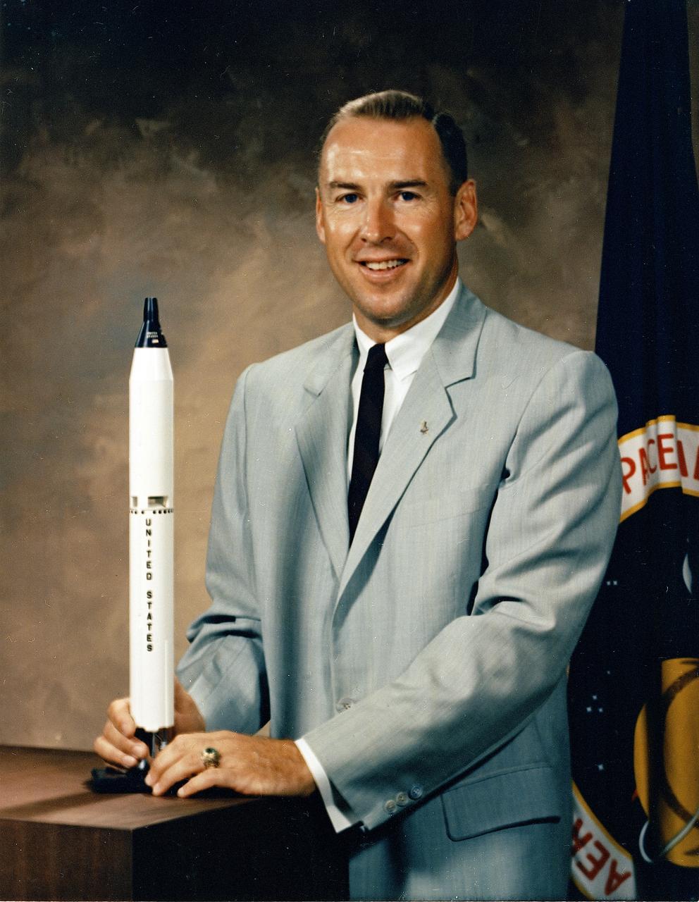
This is the official NASA portrait of astronaut James Lovell. Captain Lovell was selected as an Astronaut by NASA in September 1962. He has since served as backup pilot for the Gemini 4 flight and backup Commander for the Gemini 9 flight, as well as backup Commander to Neil Armstrong for the Apollo 11 lunar landing mission. On December 4, 1965, he and Frank Borman were launched into space on the history making Gemini 7 mission. The flight lasted 330 hours and 35 minutes and included the first rendezvous of two manned maneuverable spacecraft. The Gemini 12 mission, commanded by Lovell with Pilot Edwin Aldrin, began on November 11, 1966 for a 4-day, 59-revolution flight that brought the Gemini program to a successful close. Lovell served as Command Module Pilot and Navigator on the epic six-day journey of Apollo 8, the first manned Saturn V liftoff responsible for allowing the first humans to leave the gravitational influence of Earth. He completed his fourth mission as Spacecraft Commander of the Apollo 13 flight, April 11-17, 1970, and became the first man to journey twice to the moon. The Apollo 13 mission was cut short due to a failure of the Service Module cryogenic oxygen system. Aborting the lunar course, Lovell and fellow crewmen, John L. Swigert and Fred W. Haise, working closely with Houston ground controllers, converted their lunar module, Aquarius, into an effective lifeboat that got them safely back to Earth. Captain Lovell held the record for time in space with a total of 715 hours and 5 minutes until surpassed by the Skylab flights. On March 1, 1973, Captain Lovell retired from the Navy and the Space Program.
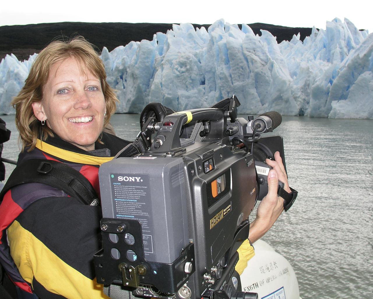
Lori Losey, an employee of Arcata Associates at Dryden, was honored with NASA's 2004 Videographer of the Year award for her work in two of the three categories in the NASA video competition, public affairs and documentation. In the public affairs category, Losey received a first-place citation for her footage of an Earth Science mission that was flown aboard NASA's DC-8 Flying Laboratory in South America last year. Her footage not only depicted the work of the scientists aboard the aircraft and on the ground, but she also obtained spectacular footage of flora and fauna in the mission's target area that helped communicate the environmental research goals of the project. Losey also took first place in the documentation category for her acquisition of technical videography of the X-45A Unmanned Combat Air Vehicle flight tests. The video, shot with a hand-held camera from the rear seat of a NASA F/A-18 mission support aircraft, demonstrated her capabilities in recording precise technical visual data in a very challenging airborne environment. The award was presented to Losey during a NASA reception at the National Association of Broadcasters convention in Las Vegas April 19. A three-judge panel evaluated entries for public affairs, documentation and production videography on professional excellence, technical quality, originality, creativity within restrictions of the project, and applicability to NASA and its mission. Entries consisted of a continuous video sequence or three views of the same subject for a maximum of three minutes duration. Linda Peters, Arcata Associates' Video Systems Supervisor at NASA Dryden, noted, "Lori is a talented videographer who has demonstrated extraordinary abilities with the many opportunities she has received in her career at NASA." Losey's award was the second major NASA video award won by members of the Dryden video team in two years. Steve Parcel took first place in the documentation category last year for his camera and editing
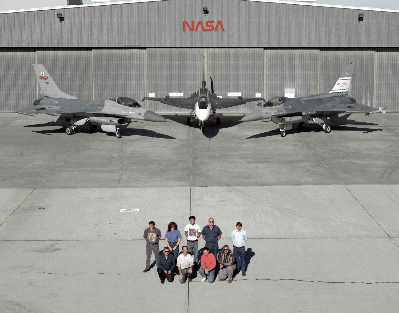
The support crew for the F-16A, the F-16XL no. 1, and the F-16 AFTI are, top row, left to right: Randy Weaver; mechanic, Susan Ligon; mechanic, Bob Garcia; Crew Chief, Rich Kelly; mechanic, Dale Edminister; Avionics Technician. Bottom row, left to right, Art Cope; mechanic, John Huffman; Avionics Technician, Jaime Garcia; Avionics Technician, Don Griffith, Avionics Tech. Co-op student. The F-16A (NASA 516), the only civil registered F-16 in existence, was transferred to Dryden from Langley, and was primarily used in engine tests and for parts. It was subsequently transfered from Dryden. The single-seat F-16XL no. 1 (NASA 849) was most recently used in the Cranked-Arrow Wing Aerodynamics Project (CAWAP) to test boundary layer pressures and distribution. Previously it had been used in a program to investigate the characteristics of sonic booms for NASA's High Speed Research Program. Data from the program will be used in the development of a high speed civilian transport. During the series of sonic boom research flights, the F-16XL was used to probe the shock waves being generated by a NASA SR-71 and record their shape and intensity. The Advanced Fighter Technology Integration (AFTI) F-16 was used to develop and demonstrate technologies to improve navigation and a pilot's ability to find and destroy enemy ground targets day or night, including adverse weather. Earlier research in the joint NASA-Air Force AFTI F-16 program demonstrated voice actuated controls, helmet-mounted sighting and integration of forward-mounted canards with the standard flight control system to achieve uncoupled flight.
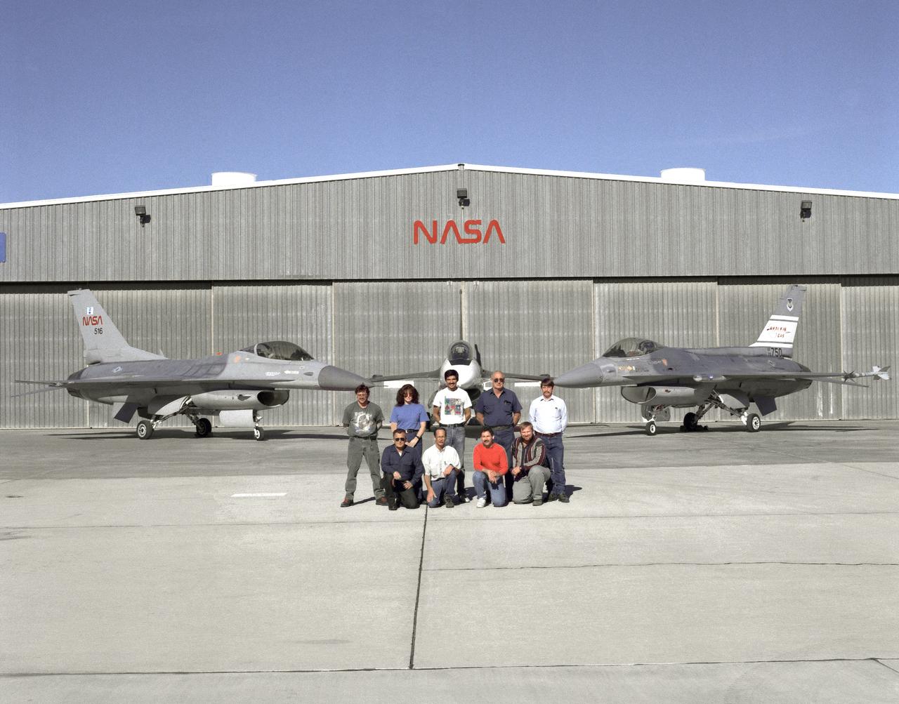
The support crew for the F-16A, the F-16XL no. 1, and the F-16 AFTI are, top row, left to right: Randy Weaver; mechanic, Susan Ligon; mechanic, Bob Garcia; Crew Chief, Rich Kelly; mechanic, Dale Edminister; Avionics Technician. Bottom row, left to right, Art Cope; mechanic, John Huffman; Avionics Technician, Jaime Garcia; Avionics Technician, Don Griffith, Avionics Tech. Co-op student. The F-16A (NASA 516), the only civil registered F-16 in existence, was transferred to Dryden from Langley, and was primarily used in engine tests and for parts. It was subsequently transfered from Dryden. The single-seat F-16XL no. 1 (NASA 849) was most recently used in the Cranked-Arrow Wing Aerodynamics Project (CAWAP) to test boundary layer pressures and distribution. Previously it had been used in a program to investigate the characteristics of sonic booms for NASA's High Speed Research Program. Data from the program will be used in the development of a high speed civilian transport. During the series of sonic boom research flights, the F-16XL was used to probe the shock waves being generated by a NASA SR-71 and record their shape and intensity. The Advanced Fighter Technology Integration (AFTI) F-16 was used to develop and demonstrate technologies to improve navigation and a pilot's ability to find and destroy enemy ground targets day or night, including adverse weather. Earlier research in the joint NASA-Air Force AFTI F-16 program demonstrated voice actuated controls, helmet-mounted sighting and integration of forward-mounted canards with the standard flight control system to achieve uncoupled flight.
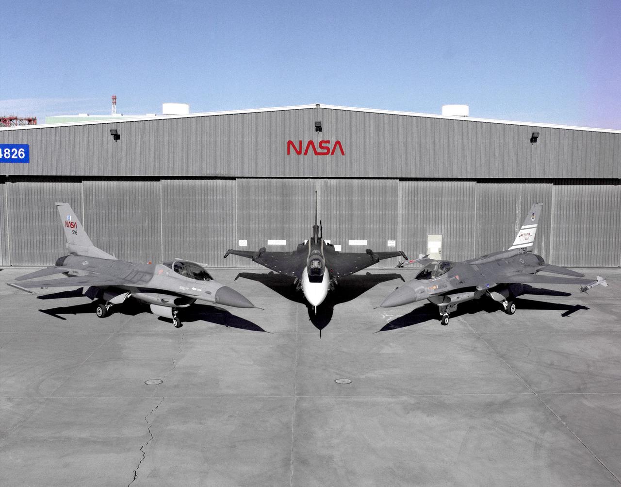
Photographed outside their hangar at the Dryden Flight Research Center, Edwards, California, part of Dryden's F-16 fleet is, left to right; an F-16A, the F-16XL no. 1, and the F-16 AFTI. The F-16A (NASA 516), the only civil registered F-16 in existence, was transferred to Dryden from Langley, and was primarily used in engine tests and for parts. It was subsequently transfered from Dryden. The single-seat F-16XL no. 1 (NASA 849) was most recently used in the Cranked-Arrow Wing Aerodynamics Project (CAWAP) to test boundary layer pressures and distribution. Previously it had been used in a program to investigate the characteristics of sonic booms for NASA's High Speed Research Program. Data from the program will be used in the development of a high speed civilian transport. During the series of sonic boom research flights, the F-16XL was used to probe the shock waves being generated by a NASA SR-71 and record their shape and intensity. The Advanced Fighter Technology Integration (AFTI) F-16 was used to develop and demonstrate technologies to improve navigation and a pilot's ability to find and destroy enemy ground targets day or night, including adverse weather. Earlier research in the joint NASA-Air Force AFTI F-16 program demonstrated voice actuated controls, helmet-mounted sighting and integration of forward-mounted canards with the standard flight control system to achieve uncoupled flight.
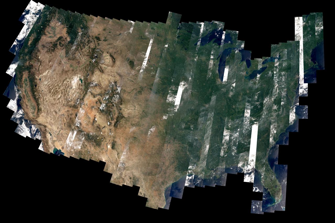
On February 11, 2013, the Landsat 8 satellite rocketed into a sunny California morning onboard a powerful Atlas V and began its life in orbit. In the year since launch, scientists have been working to understand the information the satellite has been sending back. Some have been calibrating the data—checking it against ground observations and matching it to the rest of the 42-year-long Landsat record. At the same time, the broader science community has been learning to use the new data. The map above—one of the first views of the United States from Landsat 8—is an example of how scientists are testing Landsat 8 data. David Roy, a co-leader of the USGS-NASA Landsat science team and researcher at South Dakota State University, made the map with observations taken during August 2013 by the satellite’s Operational Land Imager. Read more: <a href="http://earthobservatory.nasa.gov/IOTD/view.php?id=83099" rel="nofollow">earthobservatory.nasa.gov/IOTD/view.php?id=83099</a> Image courtesy David Roy, USGS-NASA WELD product. Caption by Holli Riebeek. Instrument: Landsat 8 - OLI Credit: <b><a href="http://www.earthobservatory.nasa.gov/" rel="nofollow"> NASA Earth Observatory</a></b> <b><a href="http://www.nasa.gov/audience/formedia/features/MP_Photo_Guidelines.html" rel="nofollow">NASA image use policy.</a></b> <b><a href="http://www.nasa.gov/centers/goddard/home/index.html" rel="nofollow">NASA Goddard Space Flight Center</a></b> enables NASA’s mission through four scientific endeavors: Earth Science, Heliophysics, Solar System Exploration, and Astrophysics. Goddard plays a leading role in NASA’s accomplishments by contributing compelling scientific knowledge to advance the Agency’s mission. <b>Follow us on <a href="http://twitter.com/NASAGoddardPix" rel="nofollow">Twitter</a></b> <b>Like us on <a href="http://www.facebook.com/pages/Greenbelt-MD/NASA-Goddard/395013845897?ref=tsd" rel="nofollow">Facebook</a></b> <b>Find us on <a href="http://instagram.com/nasagoddard?vm=grid" rel="nofollow">Instagram</a></b>
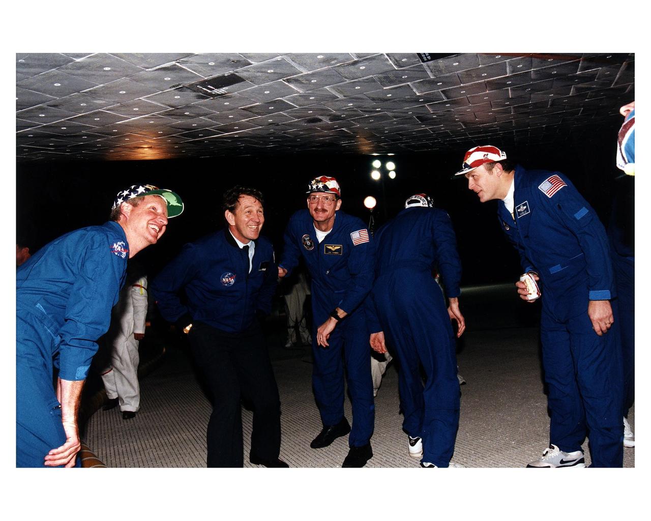
Accompanied by former astronaut Michael J. McCulley, several members of the STS-82 crew look at thermal protection system tile under the Space Shuttle Discovery on the runway at the Shuttle Landing Facility shortly after the conclusion of a 10-day mission to service the orbiting Hubble Space Telescope (HST). From left to right, they are Mission Specialist Steven A. Hawley; Michael J. McCulley, currently vice president and associate program manager for ground operations for the United Space Alliance at KSC; Mission Specialists Joseph R. "Joe" Tanner and Steven L. Smith (back to camera); and Payload Commander Mark C. Lee. STS-82 is the ninth Shuttle nighttime landing, and the fourth nighttime landing at KSC. The seven-member crew performed a record-tying five back-to-back extravehicular activities (EVAs) or spacewalks to service the telescope, which has been in orbit for nearly seven years. Two new scientific instruments were installed, replacing two outdated instruments. Five spacewalks also were performed on the first servicing mission, STS-61, in December 1993. Only four spacewalks were scheduled for STS-82, but a fifth one was added during the flight to install several thermal blankets over some aging insulation covering three HST compartments containing key data processing, electronics and scientific instrument telemetry packages. STS-82 was the 82nd Space Shuttle flight and the second mission of 1997
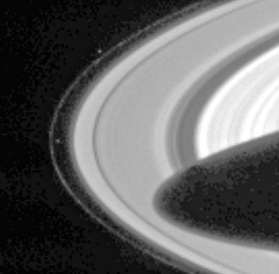
Cassini has sighted Prometheus and Pandora, the two F-ring-shepherding moons whose unpredictable orbits both fascinate scientists and wreak havoc on the F ring. Prometheus (102 kilometers, or 63 miles across) is visible left of center in the image, inside the F ring. Pandora (84 kilometers, or 52 miles across) appears above center, outside the ring. The dark shadow cast by the planet stretches more than halfway across the A ring, the outermost main ring. The mottled pattern appearing in the dark regions of the image is 'noise' in the signal recorded by the camera system, which has subsequently been magnified by the image processing. The F ring is a narrow, ribbon-like structure, with a width seen in this geometry equivalent to a few kilometers. The two small, irregularly shaped moons exert a gravitational influence on particles that make up the F ring, confining it and possibly leading to the formation of clumps, strands and other structures observed there. Pandora prevents the F ring from spreading outward and Prometheus prevents it from spreading inward. However, their interaction with the ring is complex and not fully understood. The shepherds are also known to be responsible for many of the observed structures in Saturn's A ring. The moons, which were discovered in images returned by the Voyager 1 spacecraft in 1980, are in chaotic orbits--their orbits can change unpredictably when the moons get very close to each other. This strange behavior was first noticed in ground-based and Hubble Space Telescope observations in 1995, when the rings were seen nearly edge-on from Earth and the usual glare of the rings was reduced, making the satellites more readily visible than usual. The positions of both satellites at that time were different than expected based on Voyager data. One of the goals for the Cassini-Huygens mission is to derive more precise orbits for Prometheus and Pandora. Seeing how their orbits change over the duration of the mission will help to determine their masses, which in turn will help constrain models of their interiors and provide a more complete understanding of their effect on the rings. This narrow angle camera image was snapped through the broadband green spectral filter, centered at 568 nanometers, on March 10, 2004, when the spacecraft was 55.5 million kilometers (34.5 million miles) from the planet. Image scale is approximately 333 kilometers (207 miles) per pixel. Contrast has been greatly enhanced, and the image has been magnified to aid visibility of the moons as well as structure in the rings. http://photojournal.jpl.nasa.gov/catalog/PIA05387
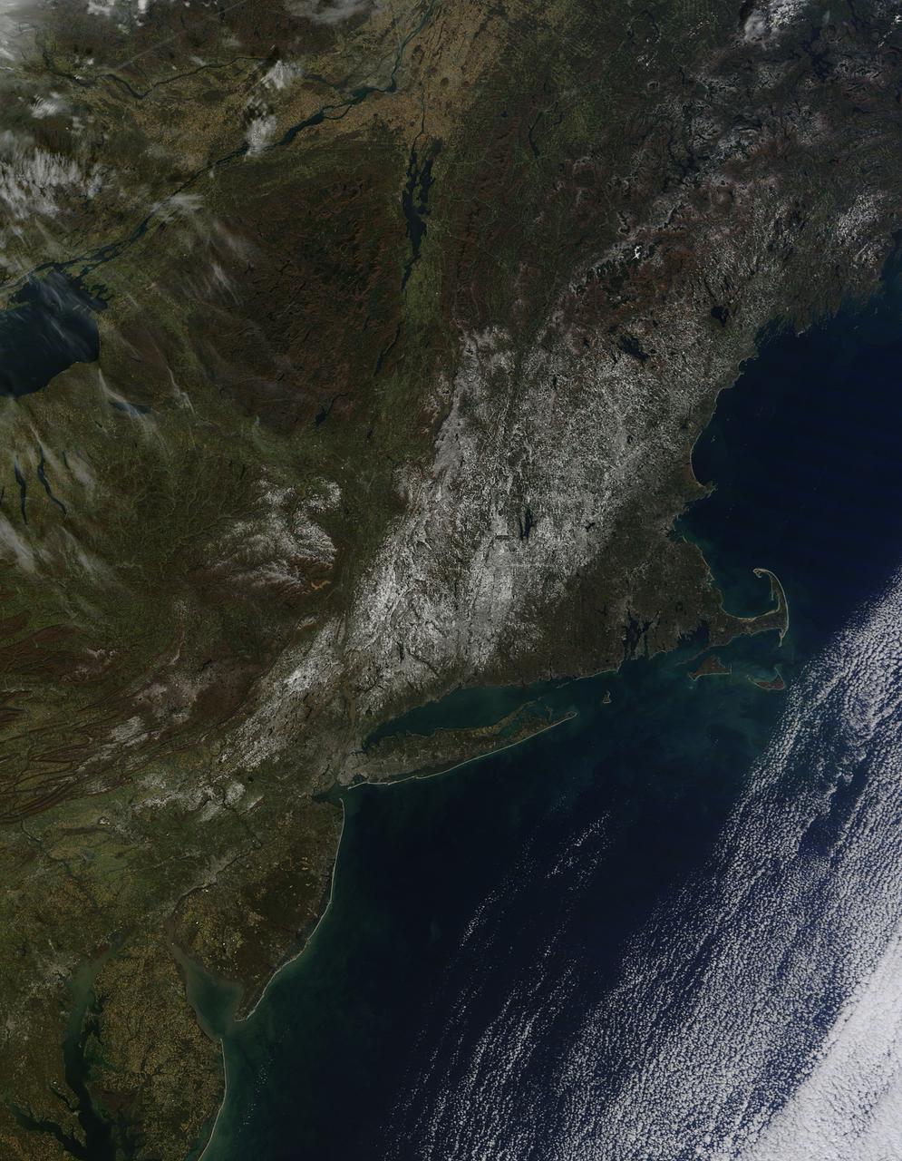
Last weekend's late October snow may have melted in Maryland, Delaware, parts of Pennsylvania and New Jersey, but residents in north central Connecticut are still dealing with the effects of the storm. According to Connecticut Light and Power, 430,868 residents were still without power today, Nov. 3, 2011. For estimated restoration times, visit their website at: <a href="http://www.cl-p.com/stormcenter/estimates/" rel="nofollow">www.cl-p.com/stormcenter/estimates/</a>. A late October snowstorm from a Nor'easter blanketed the eastern U.S. from West Virginia to Maine and broke records the weekend before Halloween Monday. NASA's Aqua satellite flew over the region on October 30 after the snow was ending in New England and captured the ghostly blanket of white. When NASA's Aqua satellite passed over the northeastern U.S. on November 2, 2011 at 2:00 p.m. EDT, the Moderate Resolution Imaging Spectroradiometer (MODIS) instrument captured a detailed image of the remaining snowfall. Snow still covers the ground in western and central Connecticut, southeastern New York, western and central Massachusetts, and parts of Vermont, New Hampshire and Maine. Over the Atlantic, cirrocumulus clouds create a diagonal border. The image was created at NASA's Goddard Space Flight Center in Greenbelt, Md. Image Credit: NASA Goddard MODIS Rapid Response Team; Caption: NASA Goddard, Rob Gutro <b><a href="http://www.nasa.gov/audience/formedia/features/MP_Photo_Guidelines.html" rel="nofollow">NASA image use policy.</a></b> <b><a href="http://www.nasa.gov/centers/goddard/home/index.html" rel="nofollow">NASA Goddard Space Flight Center</a></b> enables NASA’s mission through four scientific endeavors: Earth Science, Heliophysics, Solar System Exploration, and Astrophysics. Goddard plays a leading role in NASA’s accomplishments by contributing compelling scientific knowledge to advance the Agency’s mission. <b>Follow us on <a href="http://twitter.com/NASA_GoddardPix" rel="nofollow">Twitter</a></b> <b>Like us on <a href="http://www.facebook.com/pages/Greenbelt-MD/NASA-Goddard/395013845897?ref=tsd" rel="nofollow">Facebook</a></b> <b>Find us on <a href="http://instagrid.me/nasagoddard/?vm=grid" rel="nofollow">Instagram</a></b>

NASA image release December 14, 2010 A delicate sphere of gas, photographed by NASA's Hubble Space Telescope, floats serenely in the depths of space. The pristine shell, or bubble, is the result of gas that is being shocked by the expanding blast wave from a supernova. Called SNR 0509-67.5 (or SNR 0509 for short), the bubble is the visible remnant of a powerful stellar explosion in the Large Magellanic Cloud (LMC), a small galaxy about 160,000 light-years from Earth. Ripples in the shell's surface may be caused by either subtle variations in the density of the ambient interstellar gas, or possibly driven from the interior by pieces of the ejecta. The bubble-shaped shroud of gas is 23 light-years across and is expanding at more than 11 million miles per hour (5,000 kilometers per second). Astronomers have concluded that the explosion was one of an especially energetic and bright variety of supernovae. Known as Type Ia, such supernova events are thought to result from a white dwarf star in a binary system that robs its partner of material, takes on much more mass than it is able to handle, and eventually explodes. Hubble's Advanced Camera for Surveys observed the supernova remnant on Oct. 28, 2006 with a filter that isolates light from glowing hydrogen seen in the expanding shell. These observations were then combined with visible-light images of the surrounding star field that were imaged with Hubble's Wide Field Camera 3 on Nov. 4, 2010. With an age of about 400 years as seen from Earth, the supernova might have been visible to southern hemisphere observers around the year 1600, however, there are no known records of a "new star" in the direction of the LMC near that time. A more recent supernova in the LMC, SN 1987A, did catch the eye of Earth viewers and continues to be studied with ground- and space-based telescopes, including Hubble. For images and more information about SNR 0509, visit: <a href="http://hubblesite.org/news/2010/27" rel="nofollow">hubblesite.org/news/2010/27</a> <a href="http://heritage.stsci.edu/2010/27" rel="nofollow">heritage.stsci.edu/2010/27</a> <a href="http://www.nasa.gov/hubble" rel="nofollow">www.nasa.gov/hubble</a> The Hubble Space Telescope is a project of international cooperation between NASA and the European Space Agency. NASA's Goddard Space Flight Center manages the telescope. The Space Telescope Science Institute (STScI) conducts Hubble science operations. STScI is operated for NASA by the Association of Universities for Research in Astronomy, Inc., in Washington, D.C. <b>Credit: NASA, ESA, and the Hubble Heritage Team (STScI/AURA) Acknowledgment: J. Hughes (Rutgers University)</b> <b><a href="http://www.nasa.gov/centers/goddard/home/index.html" rel="nofollow">NASA Goddard Space Flight Center</a></b> enables NASA’s mission through four scientific endeavors: Earth Science, Heliophysics, Solar System Exploration, and Astrophysics. Goddard plays a leading role in NASA’s accomplishments by contributing compelling scientific knowledge to advance the Agency’s mission. <b>Follow us on <a href="http://twitter.com/NASA_GoddardPix" rel="nofollow">Twitter</a></b> <b>Join us on <a href="http://www.facebook.com/pages/Greenbelt-MD/NASA-Goddard/395013845897?ref=tsd" rel="nofollow">Facebook</a></b>
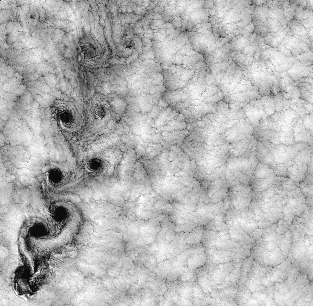
NASA image acquired September 15, 1999 This Landsat 7 image of clouds off the Chilean coast near the Juan Fernandez Islands (also known as the Robinson Crusoe Islands) on September 15, 1999, shows a unique pattern called a “von Karman vortex street.” This pattern has long been studied in the laboratory, where the vortices are created by oil flowing past a cylindrical obstacle, making a string of vortices only several tens of centimeters long. Study of this classic “flow past a circular cylinder” has been very important in the understanding of laminar and turbulent fluid flow that controls a wide variety of phenomena, from the lift under an aircraft wing to Earth’s weather. Here, the cylinder is replaced by Alejandro Selkirk Island (named after the true “Robinson Crusoe,” who was stranded here for many months in the early 1700s). The island is about 1.5 km in diameter, and rises 1.6 km into a layer of marine stratocumulus clouds. This type of cloud is important for its strong cooling of the Earth’s surface, partially counteracting the Greenhouse warming. An extended, steady equatorward wind creates vortices with clockwise flow off the eastern edge and counterclockwise flow off the western edge of the island. The vortices grow as they advect hundreds of kilometers downwind, making a street 10,000 times longer than those made in the laboratory. Observing the same phenomenon extended over such a wide range of sizes dramatizes the “fractal” nature of atmospheric convection and clouds. Fractals are characteristic of fluid flow and other dynamic systems that exhibit “chaotic” motions. Both clockwise and counter-clockwise vortices are generated by flow around the island. As the flow separates from the island’s leeward (away from the source of the wind) side, the vortices “swallow” some of the clear air over the island. (Much of the island air is cloudless due to a local “land breeze” circulation set up by the larger heat capacity of the waters surrounding the island.) The “swallowed” gulps of clear island air get carried along within the vortices, but these are soon mixed into the surrounding clouds. Landsat is unique in its ability to image both the small-scale eddies that mix clear and cloudy air, down to the 30 meter pixel size of Landsat, but also having a wide enough field-of-view, 180 km, to reveal the connection of the turbulence to large-scale flows such as the subtropical oceanic gyres. Landsat 7, with its new onboard digital recorder, has extended this capability away from the few Landsat ground stations to remote areas such as Alejandro Island, and thus is gradually providing a global dynamic picture of evolving human-scale phenomena. For more details on von Karman vortices, refer to <a href="http://climate.gsfc.nasa.gov/~cahalan" rel="nofollow">climate.gsfc.nasa.gov/~cahalan</a>. Image and caption courtesy Bob Cahalan, NASA GSFC Instrument: Landsat 7 - ETM+ Credit: NASA/GSFC/Landsat <b><a href="http://www.nasa.gov/centers/goddard/home/index.html" rel="nofollow">NASA Goddard Space Flight Center</a></b> enables NASA’s mission through four scientific endeavors: Earth Science, Heliophysics, Solar System Exploration, and Astrophysics. Goddard plays a leading role in NASA’s accomplishments by contributing compelling scientific knowledge to advance the Agency’s mission. <b>Follow us on <a href="http://twitter.com/NASA_GoddardPix" rel="nofollow">Twitter</a></b> <b>Join us on <a href="http://www.facebook.com/pages/Greenbelt-MD/NASA-Goddard/395013845897?ref=tsd" rel="nofollow">Facebook</a></b>
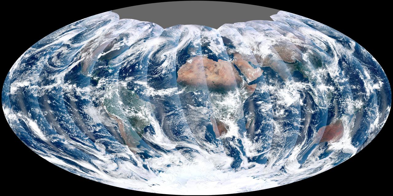
NASA acquired November 24, 2011 From its vantage 824 kilometers (512 miles) above Earth, the Visible Infrared Imager Radiometer Suite (VIIRS) on the NPOESS Preparatory Project (NPP) satellite gets a complete view of our planet every day. This image from November 24, 2011, is the first complete global image from VIIRS. The NPP satellite launched on October 28, 2011, and VIIRS acquired its first measurements on November 21. To date, the images are preliminary, used to gauge the health of the sensor as engineers continue to power it up for full operation. Rising from the south and setting in the north on the daylight side of Earth, VIIRS images the surface in long wedges measuring 3,000 kilometers (1,900 miles) across. The swaths from each successive orbit overlap one another, so that at the end of the day, the sensor has a complete view of the globe. The Arctic is missing because it is too dark to view in visible light during the winter. The NPP satellite was placed in a Sun-synchronous orbit, a unique path that takes the satellite over the equator at the same local (ground) time in every orbit. So, when NPP flies over Kenya, it is about 1:30 p.m. on the ground. When NPP reaches Gabon—about 3,000 kilometers to the west—on the next orbit, it is close to 1:30 p.m. on the ground. This orbit allows the satellite to maintain the same angle between the Earth and the Sun so that all images have similar lighting. The consistent lighting is evident in the daily global image. Stripes of sunlight (sunglint) reflect off the ocean in the same place on the left side of every swath. The consistent angle is important because it allows scientists to compare images from year to year without worrying about extreme changes in shadows and lighting. The image also shows a band of haze along the right side of every orbit swath. When light travels through the atmosphere, it bounces off particles or scatters, making the atmosphere look hazy. The scattering effect is most pronounced along the edge of the swath, where the sensor is looking at an angle through more of the atmosphere. Scientists can correct for this scattering effect, but need measurements from a range of wavelengths to do so. The degree to which light scatters depends partly on the wavelength of the light. Blue light scatters more than red light, for example, which is why the sky is blue. VIIRS measures 22 different wavelengths of light, but not all of the sensor’s detectors are operating at peak performance yet. Those measuring thermal infrared light are not yet cold enough to collect reliable measurements. Once VIIRS begins full operations, it will produce a range of measurements from ocean temperature to clouds to the locations of fires. These measurements will help extend the record from earlier sensors like the Moderate Resolution Imaging Spectroradiometer (MODIS). VIIRS is very similar to MODIS, but flies at a higher altitude to measure the whole planet without gaps. (MODIS daily measurements have gaps at the equator. See the MODIS image from November 24.) VIIRS also sees the Earth in less detail, 375 meters per pixel, compared to 250 meters per pixel for MODIS. Image by NASA’s NPP Land Product Evaluation and Testing Element. Caption by Holli Riebeek. Credit: <b><a href="http://www.earthobservatory.nasa.gov/" rel="nofollow"> NASA Earth Observatory</a></b> <b><a href="http://www.nasa.gov/audience/formedia/features/MP_Photo_Guidelines.html" rel="nofollow">NASA image use policy.</a></b> <b><a href="http://www.nasa.gov/centers/goddard/home/index.html" rel="nofollow">NASA Goddard Space Flight Center</a></b> enables NASA’s mission through four scientific endeavors: Earth Science, Heliophysics, Solar System Exploration, and Astrophysics. Goddard plays a leading role in NASA’s accomplishments by contributing compelling scientific knowledge to advance the Agency’s mission. <b>Follow us on <a href="http://twitter.com/NASA_GoddardPix" rel="nofollow">Twitter</a></b> <b>Like us on <a href="http://www.facebook.com/pages/Greenbelt-MD/NASA-Goddard/395013845897?ref=tsd" rel="nofollow">Facebook</a></b> <b>Find us on <a href="http://instagrid.me/nasagoddard/?vm=grid" rel="nofollow">Instagram</a></b>