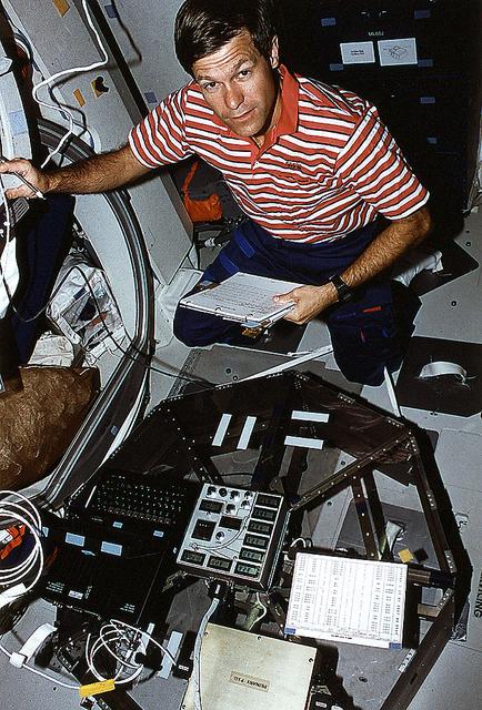
On the Space Shuttle Orbiter Atlantis' middeck, Astronaut Donald R. McMonagle, mission commander, works with the Heat Pipe Performance (HPP-2) experiment during STS-66 mission. HPP-2 was flown to investigate the thermal performance and fluid dynamics of heat pipes operating with asymmetric and multiple heating zones under microgravity condition.
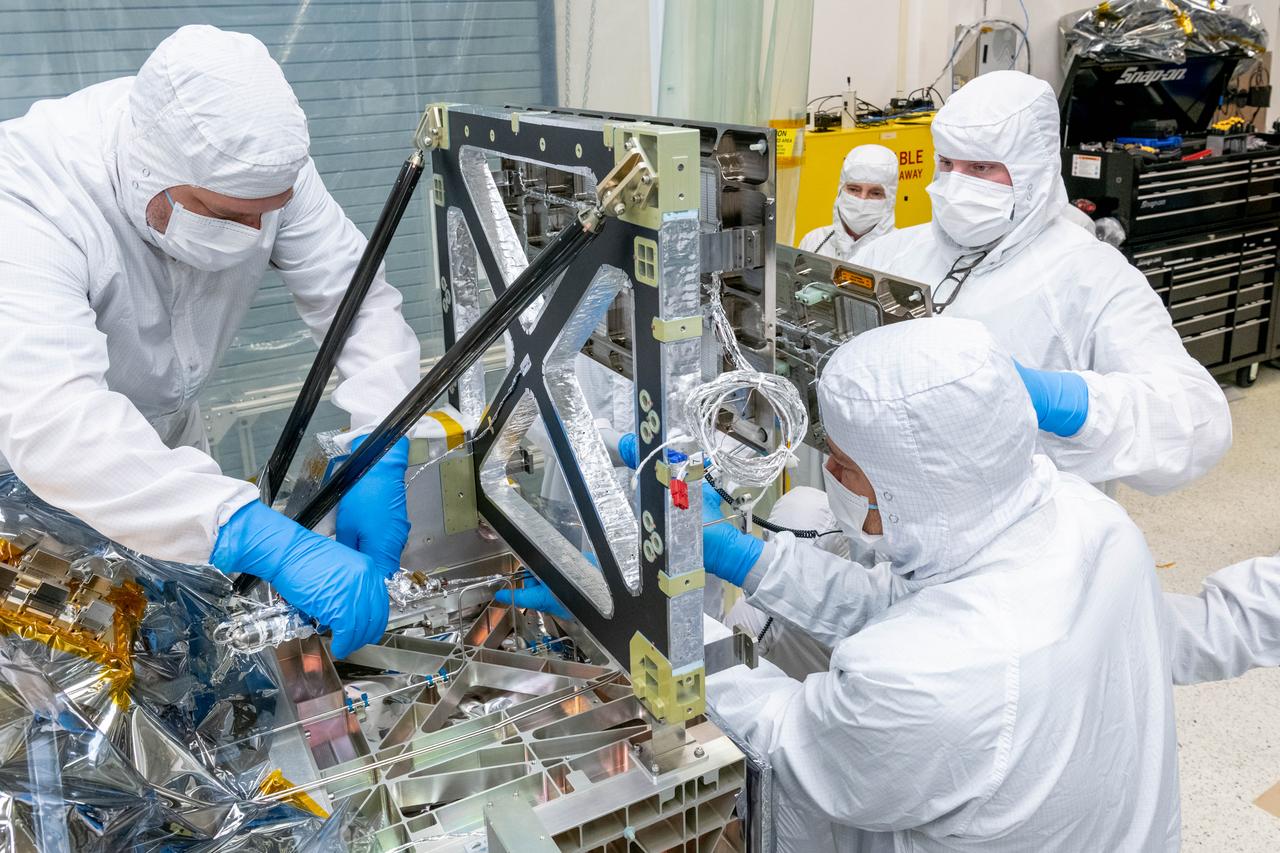
Mechanical technicians and thermal engineers work together to carefully feed the lines of a Loop Heat Pipe onto the Ocean Color Instrument (OCI). This integration operation will allow proper heat transfer throughout the instrument. OCI is a highly advanced optical spectrometer that will be used to measure properties of light over portions of the electromagnetic spectrum. It will enable continuous measurement of light at finer wavelength resolution than previous NASA satellite sensors, extending key system ocean color data records for climate studies. OCI is PACE's (Plankton, Aerosol, Cloud, ocean Ecosystem) primary sensor built at Goddard Space Flight Center in Greenbelt, MD.
Mechanical technicians and thermal engineers work together to carefully feed the lines of a Loop Heat Pipe onto the Ocean Color Instrument (OCI). This integration operation will allow proper heat transfer throughout the instrument. OCI is a highly advanced optical spectrometer that will be used to measure properties of light over portions of the electromagnetic spectrum. It will enable continuous measurement of light at finer wavelength resolution than previous NASA satellite sensors, extending key system ocean color data records for climate studies. OCI is PACE's (Plankton, Aerosol, Cloud, ocean Ecosystem) primary sensor built at Goddard Space Flight Center in Greenbelt, MD.
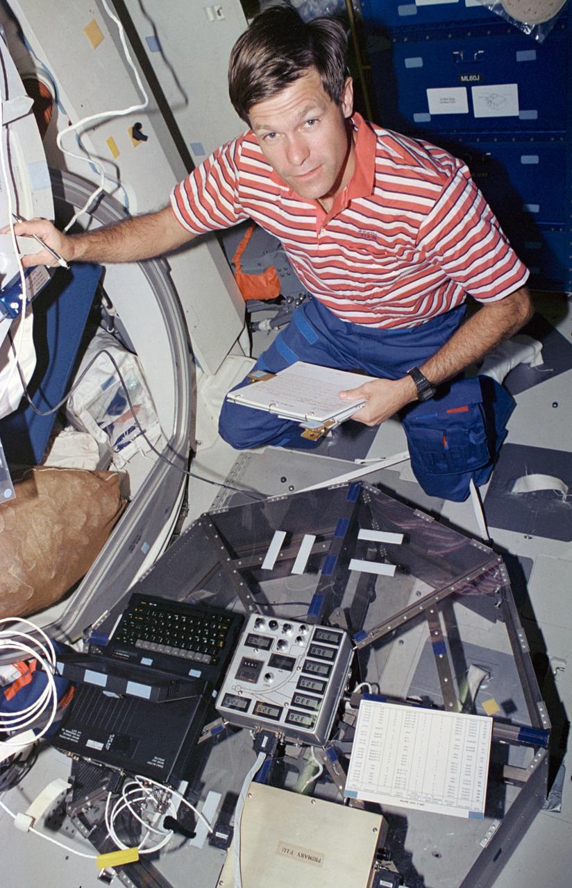
STS066-22-012 (3-14 Nov 1994) --- On the Space Shuttle Atlantis' mid-deck, astronaut Donald R. McMonagle, mission commander, works with the Heat Pipe Performance (HPP-2) experiment. HPP-2 was flown to investigate the thermal performance and fluid dynamics of heat pipes operating with asymmetric and multiple heating zones under microgravity conditions. McMonagle was joined by four other NASA astronauts and a European Space Agency (ESA) astronaut for 11-days aboard Atlantis in Earth-orbit in support of the Atmospheric Laboratory for Applications and Science (ATLAS-3) mission.
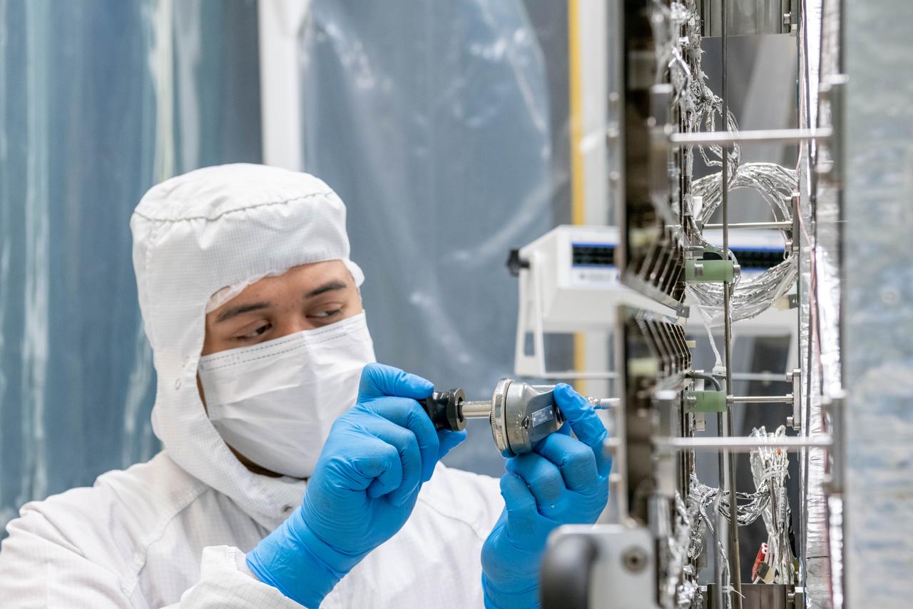
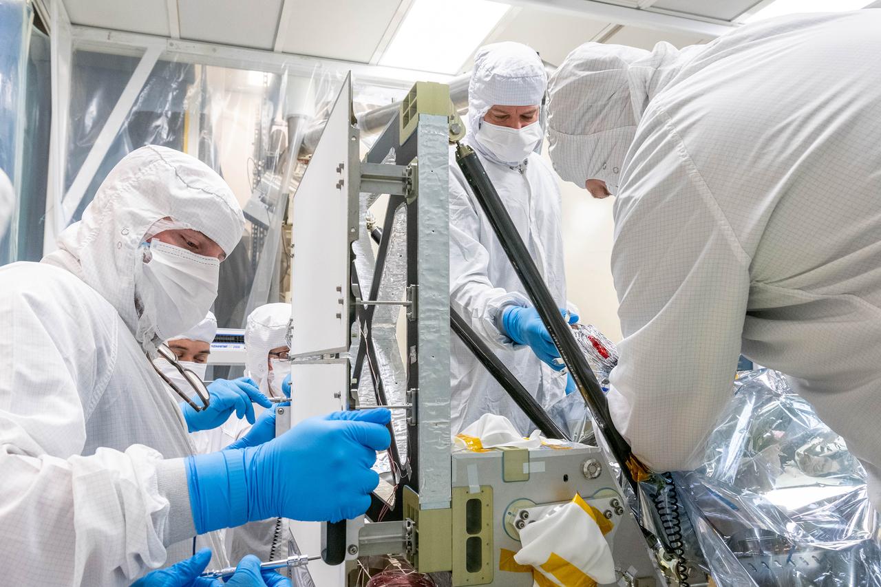
Mechanical technician, Dan Dizon, tightens bolts on the loop heat pipe radiator on the Ocean Color Instrument (OCI) in a clean tent where the final hardware of the OCI are installed and tested. OCI is a highly advanced optical spectrometer that will be used to measure properties of light over portions of the electromagnetic spectrum. It will enable continuous measurement of light at finer wavelength resolution than previous NASA satellite sensors, extending key system ocean color data records for climate studies. OCI is PACE's (Plankton, Aerosol, Cloud, ocean Ecosystem) primary sensor built at Goddard Space Flight Center in Greenbelt, MD.
S89-25873 (Nov 1988) --- The Space Station Heat Pipe Advanced Radiator Element (SHARE) is readied for installation in late November at Kennedy Space Center's orbiter processing facility (OPF). The SHARE device will be carried on a pedestel in Discovery's cargo bay during the five-day STS-29 mission, scheduled for a mid-March 1989 launch.
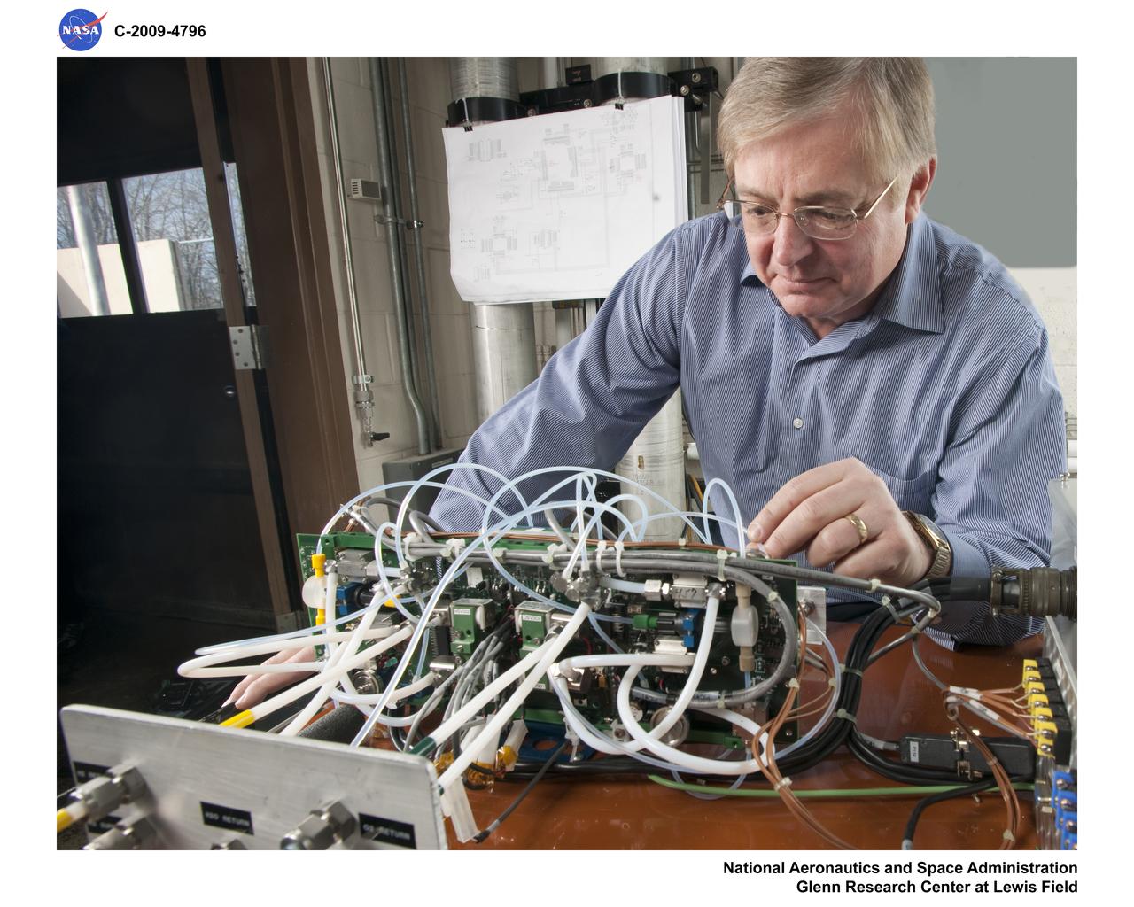
the heat pipe stack, Fuel Cell Laboratory
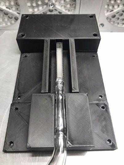
jsc2022e031220 (4/26/2022) --- A preflight image showing the Phase Change in Mixtures (PCIM) heat pipe module in its proposed housing. Microgravity Research for Versatile Investigations-Phase Change in Mixtures (MaRVIn-PCIM) examines the distribution of vapor and liquid within a wickless heat pipe. Image courtesy of Tec-Masters, Inc.
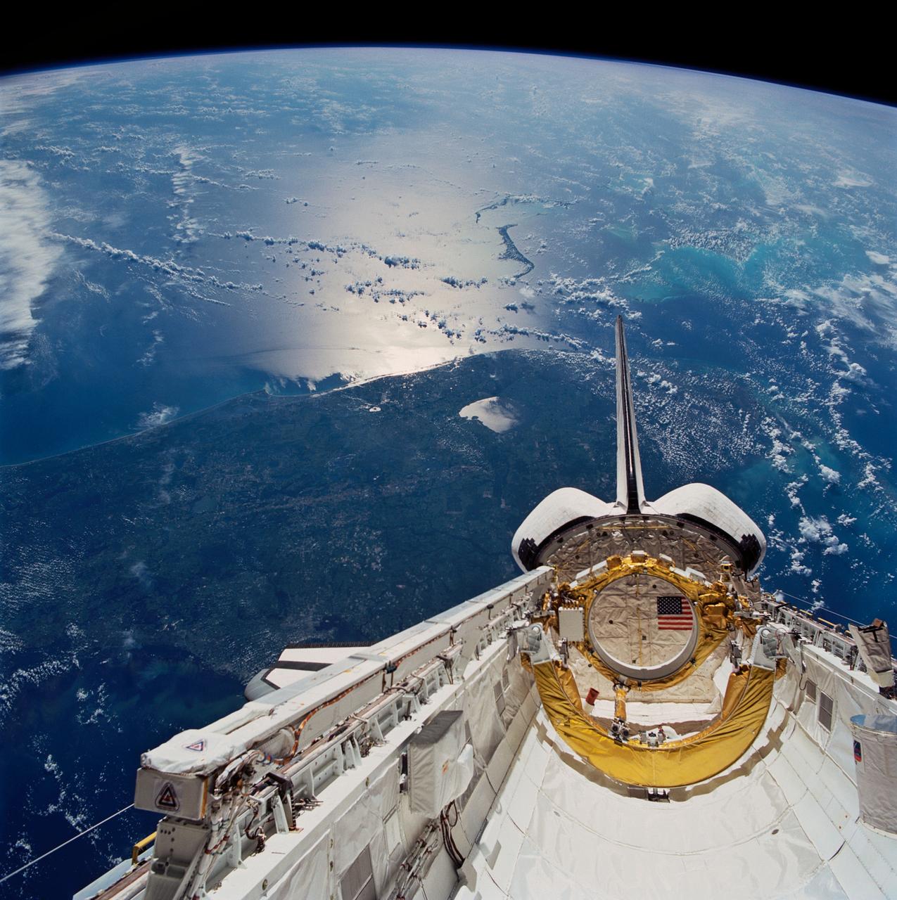
STS043-83-082 (2-11 Aug 1991) --- Having bade farewell to its Tracking and Data Relay Satellite/IUS payload, Atlantis' cargo bay appears somewhat vacant in this scene, backdropped over the southern two-thirds of the Florida peninsula. Important activity in the payload bay continues, however, with the operation of Space Station Heat Pipe Advanced Radiator Element (SHARE II), an experiment carried on the starboard side (lower left quadrant of frame). Purpose of the SHARE experiment is to demonstrate microgravity thermal vacuum performance of a heat pipe radiator for heat rejection as a prelude to development of a Space Station heat rejection system. The foil covered ring and horseshoe shaped objects aft in the payload bay served as restraint devices for the TDRS-E prior to its deployment six hours after Atlantis lifted off from Kennedy Space Center's Launch Pad 39A.
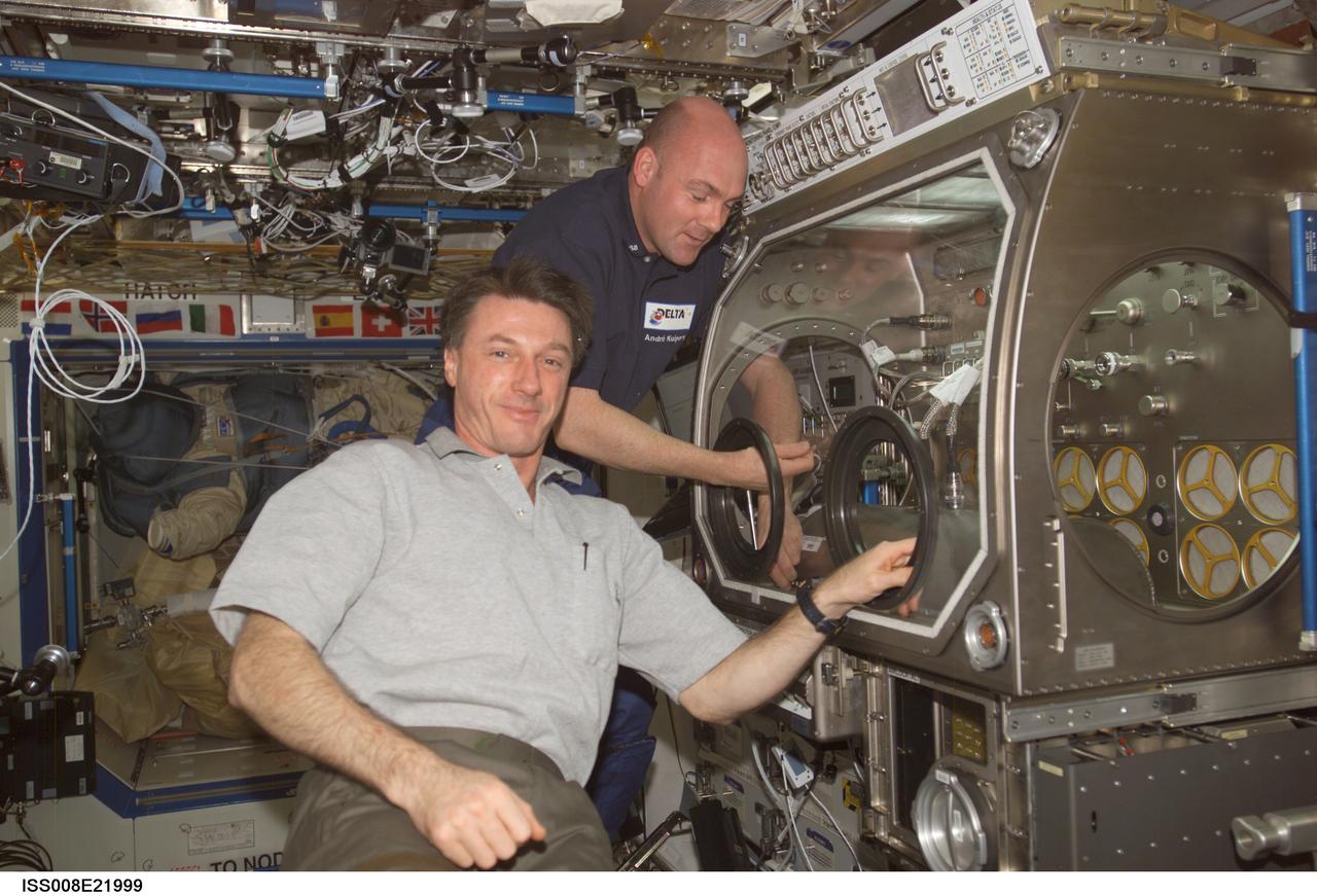
ISS008-E-21999 (22 April 2004) --- Astronaut C. Michael Foale (foreground), Expedition 8 commander and NASA ISS science officer, and European Space Agency (ESA) astronaut Andre Kuipers of the Netherlands work with the HEAT experiment in the Microgravity Science Glovebox (MSG) in the Destiny laboratory of the International Space Station (ISS). The main aim of the HEAT technology demonstration is the characterization of the heat transfer performance of a grooved heat pipe in weightlessness.
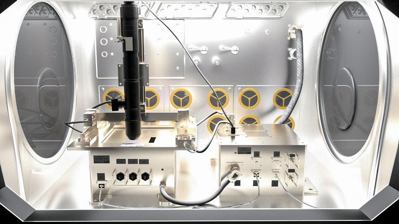
jsc2022e031219 (4/26/2022) A preflight image showing the Microgravity Research for Versatile Investigations-Phase Change in Mixtures.(MaRVIin PCIM) system as it would be housed in the microgravity glovebox facility on the ISS. The Microgravity Research for Versatile Investigations-Phase Change in Mixtures (MaRVIn-PCIM) examines the distribution of vapor and liquid within a wickless heat pipe.
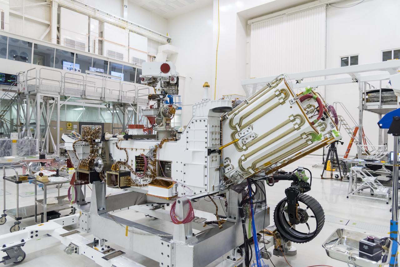
The electricity needed to operate NASA's Mars 2020 rover is provided by a power system called a Multi-Mission Radioisotope Thermoelectric Generator, or MMRTG. The MMRTG will be inserted into the aft end of the rover between the panels with gold tubing visible at the rear, which are called heat exchangers. Essentially a nuclear battery, an MMRTG uses the heat from the natural radioactive decay of plutonium-238 to generate about 110 watts of electricity at the start of a mission. Besides generating useful electrical power, the MMRTG produces heat. Some of this heat can be used to maintain the rover's systems at the proper operating temperatures in the frigid cold of space and on the surface of Mars. Some of it is rejected into space via the rover's Heat Rejection System. The gold-colored tubing on the heat exchangers form part of the cooling loops of that system. The tubes carry a fluid coolant called Trichlorofluoromethane (CFC-11) that helps dissipate the excess heat. The same tubes are used to pipe some of the heat back into the belly of the rover. MMRTGs are provided to NASA for civil space applications by the U.S. Department of Energy (DOE). The radioisotope fuel is inserted into the MMRTG at the DOE's Idaho National Laboratory before the MMRTG is shipped to the launch site. Electrically heated versions of the MMRTG are used at JPL to verify and practice integration of the power system with the rover. https://photojournal.jpl.nasa.gov/catalog/PIA23305
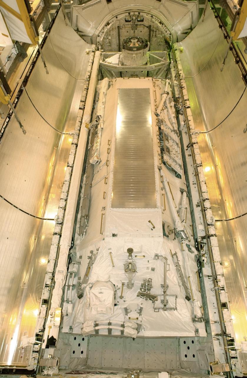
KENNEDY SPACE CENTER, FLA. -- At Launch Pad 39B, Space Shuttle Atlantis' payload bay doors are ready to be closed. The Shuttle payload includes the S0 Integrated Truss Structure (ITS), the Canadian Mobile Transporter, power distribution system modules, a heat pipe radiator for cooling, computers and a pair of rate gyroscopes. The mission is the 13th assembly flight to the ISS and includes four spacewalks to attach the S0 truss to the U.S. Lab Destiny. Launch is scheduled for April 4.
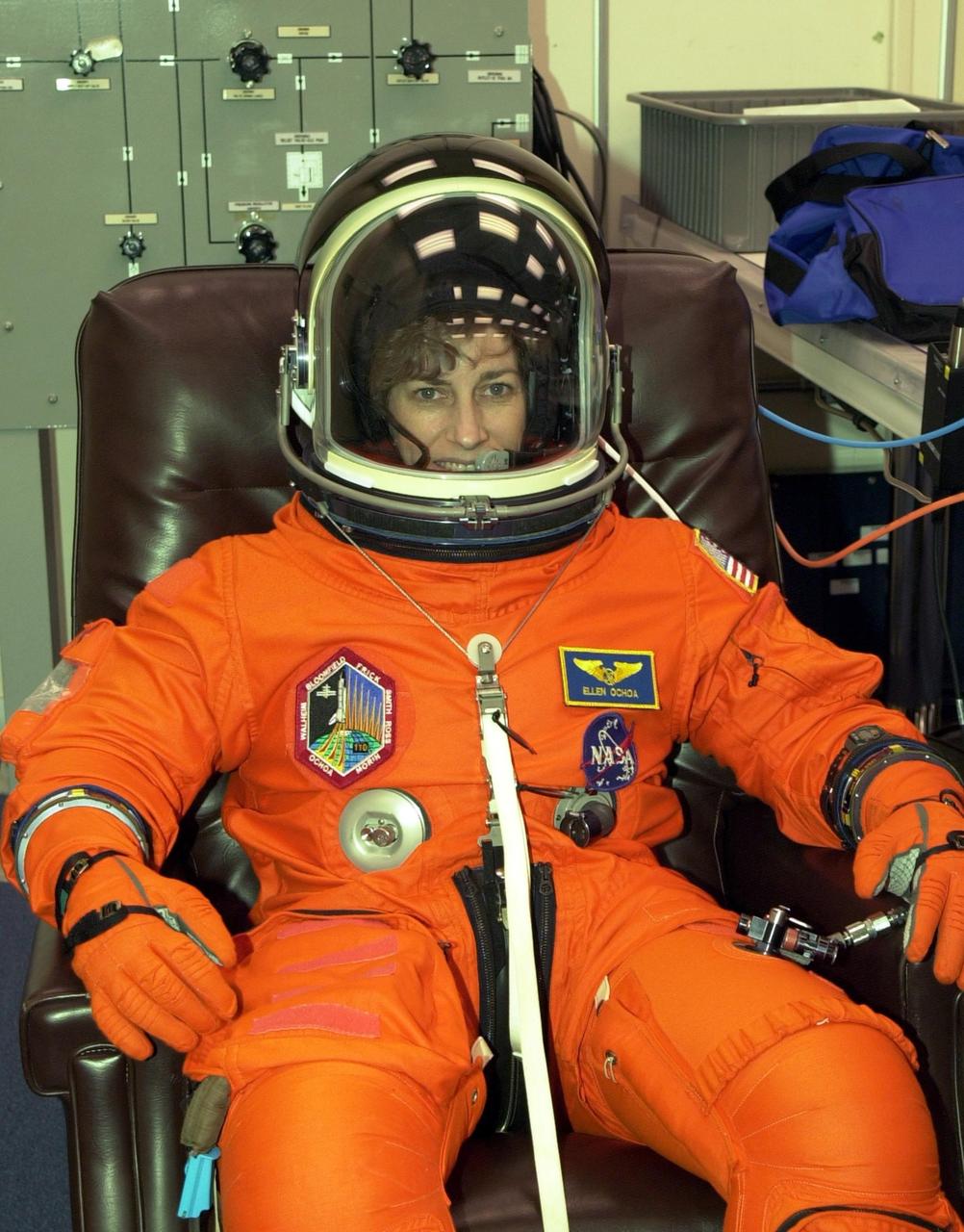
KENNEDY SPACE CENTER, FLA. -- STS-110 Mission Specialist Ellen Ochoa has a final check of her launch and entry suit in preparation for launch April 4. This flight will be her fourth. The STS-110 payload includes the S0 Integrated Truss Structure (ITS), the Canadian Mobile Transporter, power distribution system modules, a heat pipe radiator for cooling, computers and a pair of rate gyroscopes. The 11-day mission is the 13th assembly flight to the ISS and includes four spacewalks to attach the S0 truss to the U.S. Lab Destiny
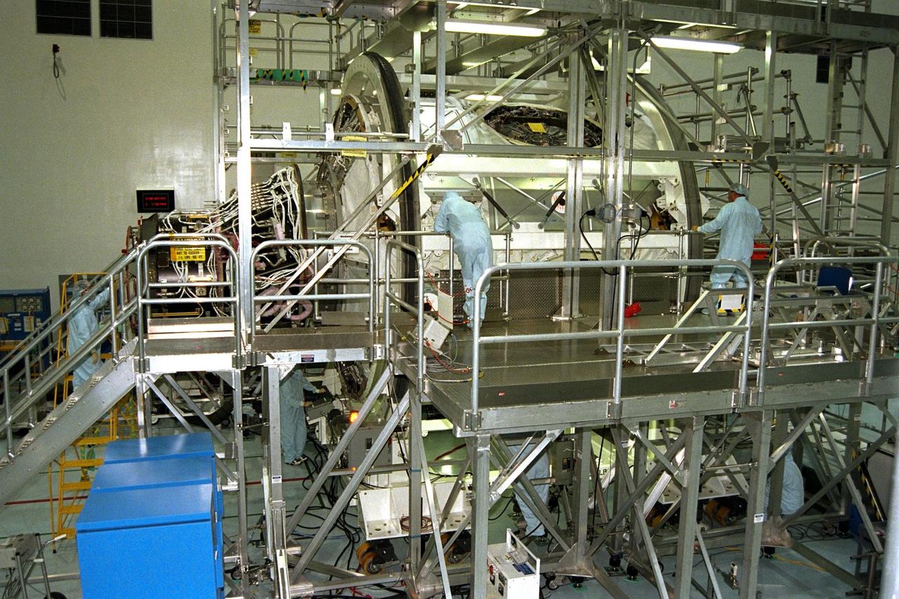
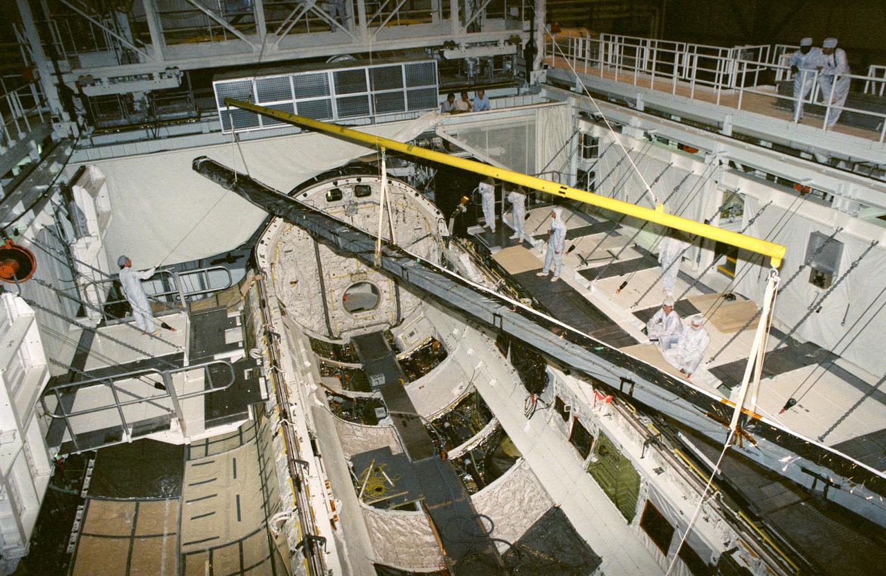
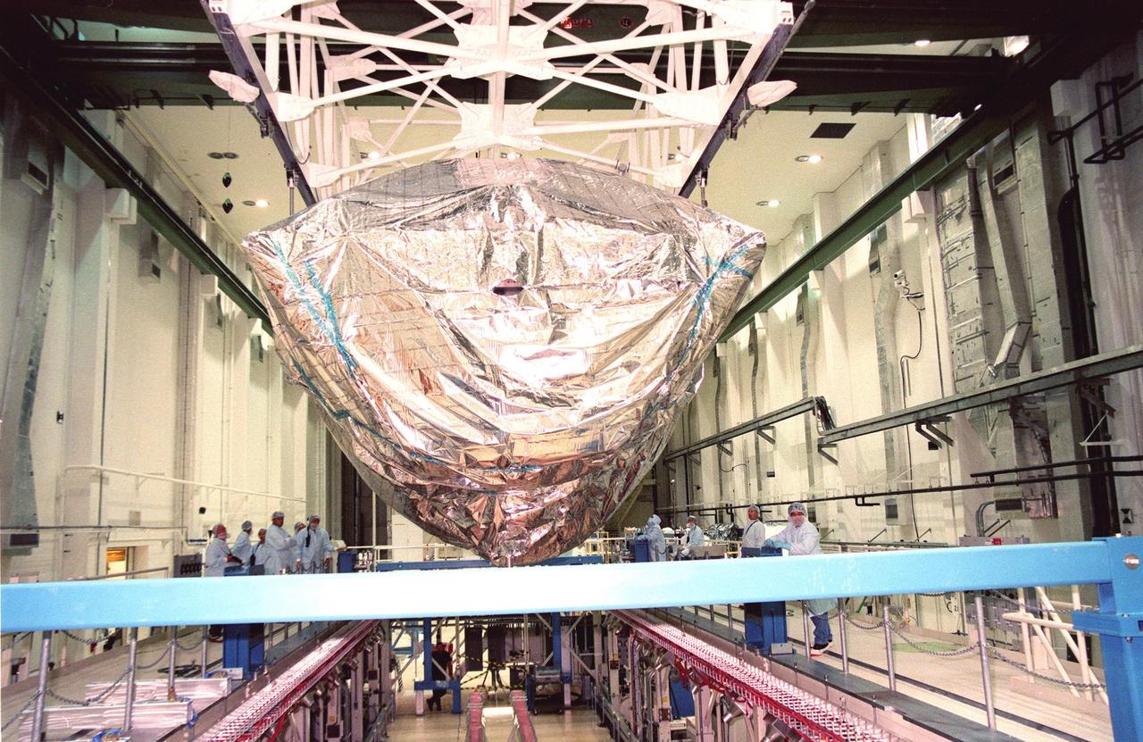
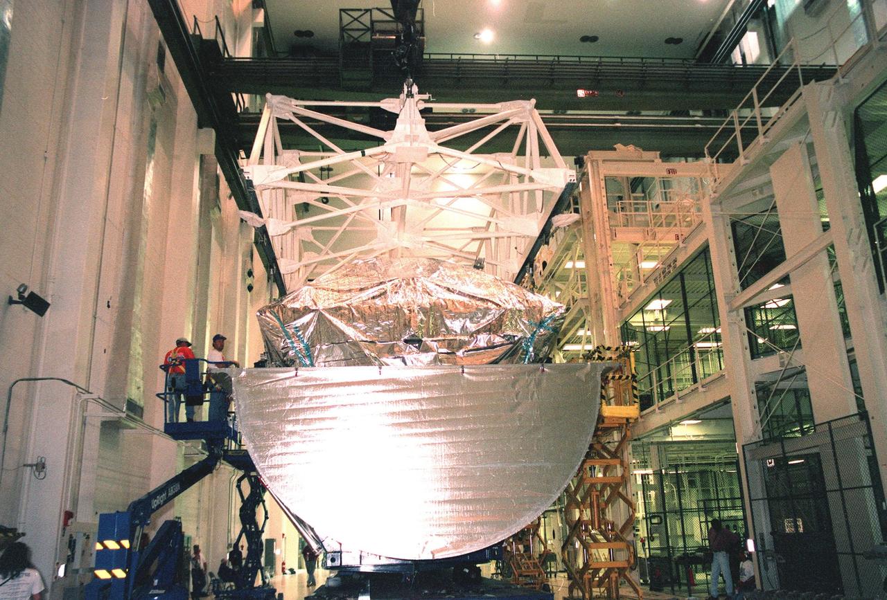
KENNEDY SPACE CENTER, FLA. -- The International Space Station's Node 1 and Pressurized Mating Adapter-1 (PMA-1) are rotated by workers in KSC's Space Station Processing Facility. The node is rotated to provide access to different areas of the flight element for processing. Here, the node is rotated to provide access for the installation of heat pipe radiators and a flight computer. The node is scheduled to launch into space on STS-88, slated for a July 9 liftoff at 1:11 p.m. from KSC's Launch Pad 39B
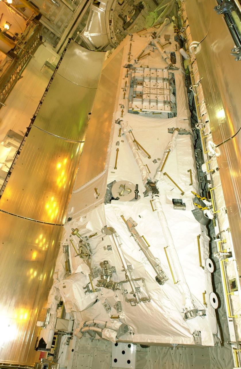
KENNEDY SPACE CENTER, FLA. -- At Launch Pad 39B, Space Shuttle Atlantis' payload bay doors are ready to be closed. The Shuttle payload includes the S0 Integrated Truss Structure (ITS), the Canadian Mobile Transporter, power distribution system modules, a heat pipe radiator for cooling, computers and a pair of rate gyroscopes. The mission is the 13th assembly flight to the ISS and includes four spacewalks to attach the S0 truss to the U.S. Lab Destiny. Launch is scheduled for April 4.

KENNEDY SPACE CENTER, FLA. -- The International Space Station's Node 1 and Pressurized Mating Adapter-1 (PMA-1) are rotated by workers in KSC's Space Station Processing Facility. The node is rotated to provide access to different areas of the flight element for processing. Here, the node is rotated to provide access for the installation of heat pipe radiators and a flight computer. The node is scheduled to launch into space on STS-88, slated for a July 9 liftoff at 1:11 p.m. from KSC's Launch Pad 39B
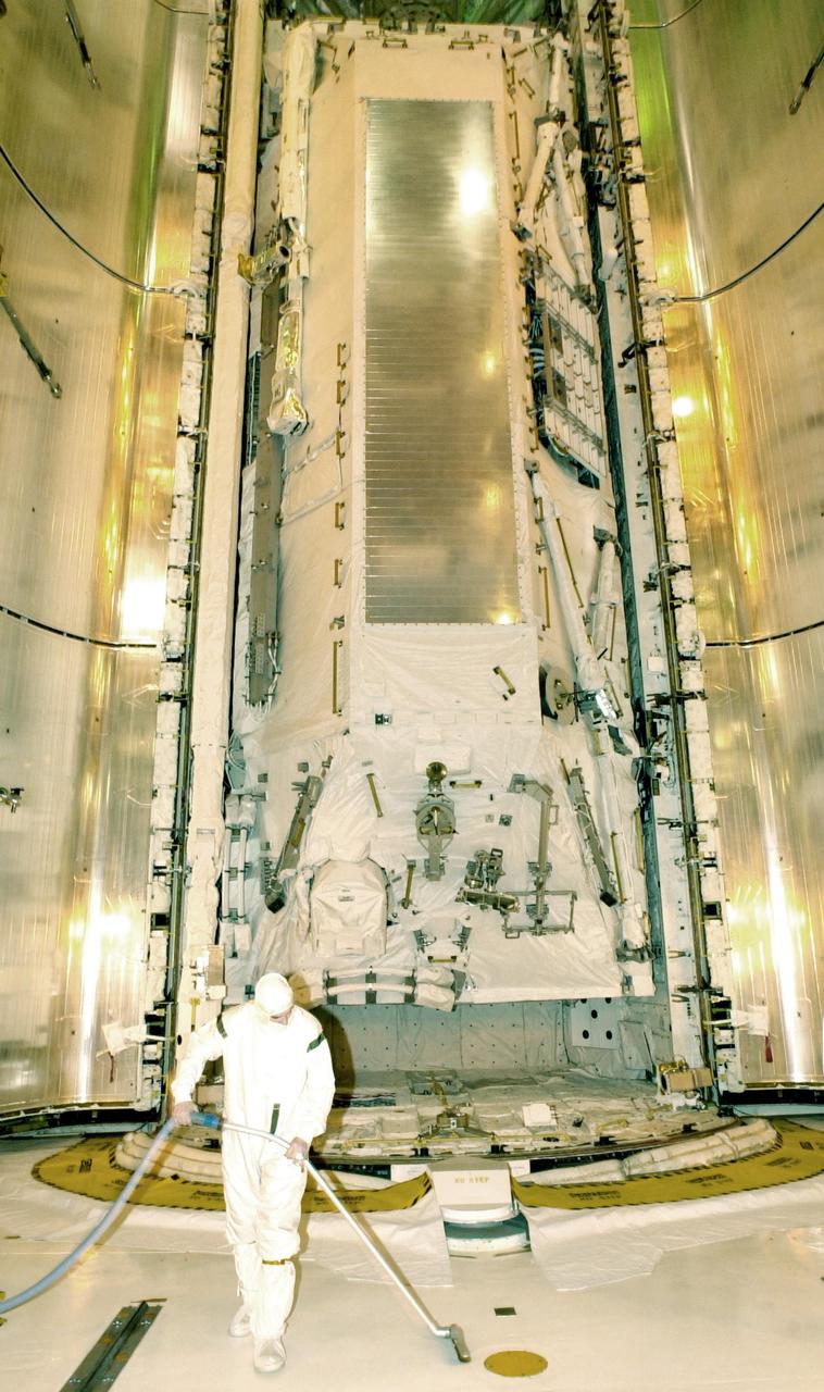
KENNEDY SPACE CENTER, FLA. - A worker at Launch Pad 39B prepares for the closing of Space Shuttle Atlantis' payload bay doors. The Shuttle payload includes the S0 Integrated Truss Structure (ITS), the Canadian Mobile Transporter, power distribution system modules, a heat pipe radiator for cooling, computers and a pair of rate gyroscopes. The mission is the 13th assembly flight to the ISS and includes four spacewalks to attach the S0 truss to the U.S. Lab Destiny. Launch is scheduled for April 4.
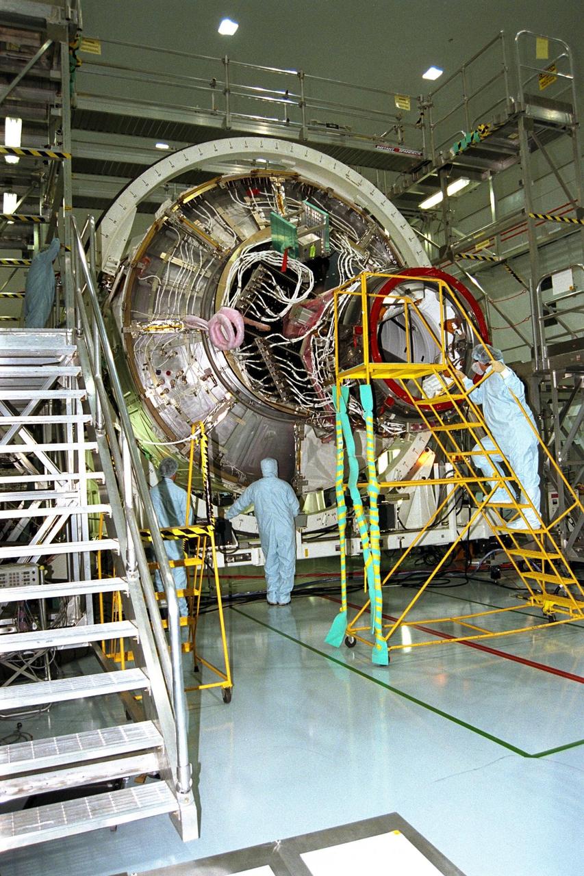
KENNEDY SPACE CENTER, FLA. -- The International Space Station's Node 1 and Pressurized Mating Adapter-1 (PMA-1) are rotated by workers in KSC's Space Station Processing Facility. The node is rotated to provide access to different areas of the flight element for processing. Here, the node is rotated to provide access for the installation of heat pipe radiators and a flight computer. The node is scheduled to launch into space on STS-88, slated for a July 9 liftoff at 1:11 p.m. from KSC's Launch Pad 39B.
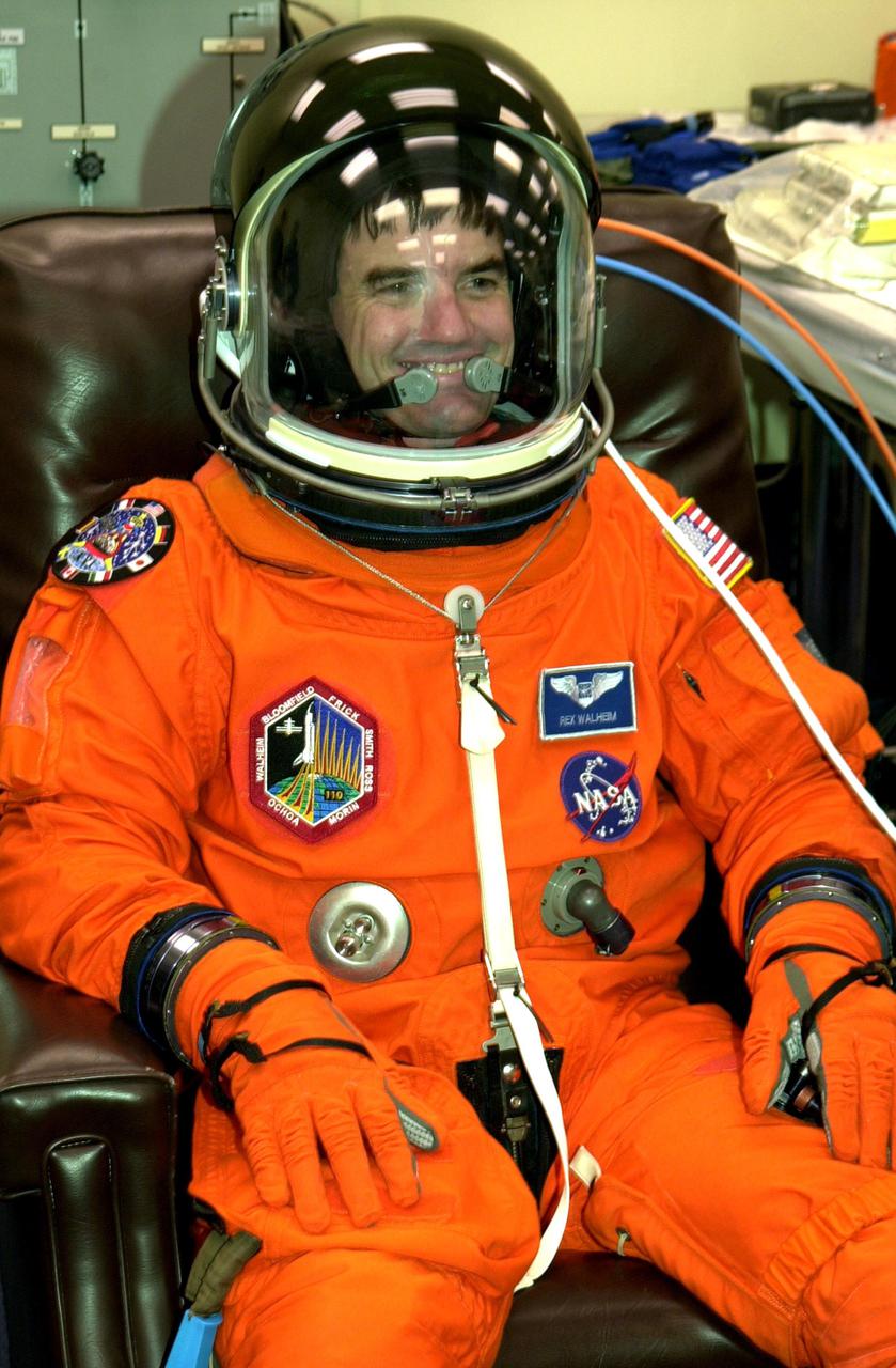
KENNEDY SPACE CENTER, FLA. -- STS-110 Mission Specialist Rex Walheim rests comfortably in his launch and entry suit during final suit check. This will be his first Shuttle flight. The STS-110 payload includes the S0 Integrated Truss Structure (ITS), the Canadian Mobile Transporter, power distribution system modules, a heat pipe radiator for cooling, computers and a pair of rate gyroscopes. The 11-day mission is the 13th assembly flight to the ISS and includes four spacewalks to attach the S0 truss to the U.S. Lab Destiny. Launch is scheduled for April 4
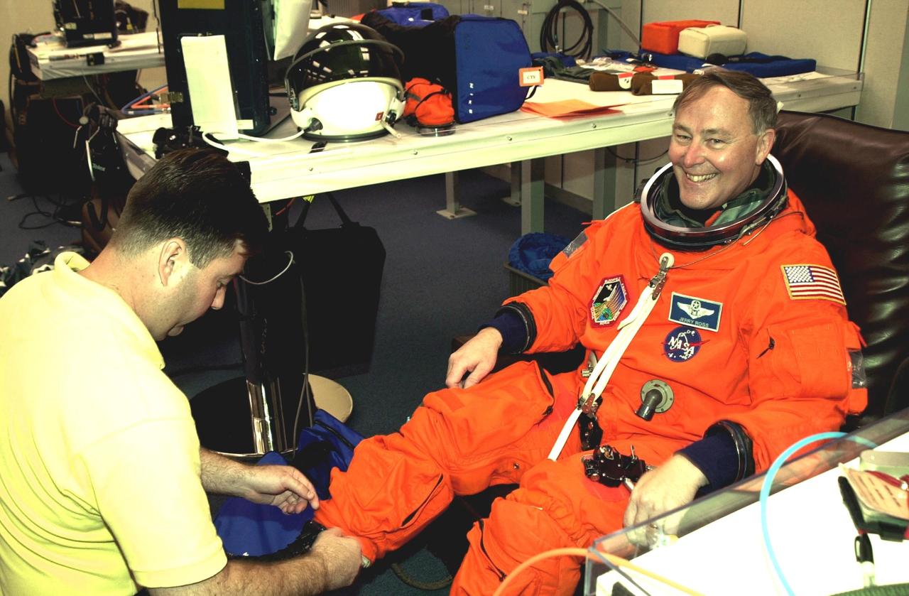
KENNEDY SPACE CENTER, FLA. -- As he undergoes a final check on his launch and entry suit, STS-110 Mission Specialist Jerry Ross shows his delight in the upcoming launch. Ross will be making a record-breaking seventh Shuttle flight. The STS-110 payload includes the S0 Integrated Truss Structure (ITS), the Canadian Mobile Transporter, power distribution system modules, a heat pipe radiator for cooling, computers and a pair of rate gyroscopes. The 11-day mission is the 13th assembly flight to the ISS and includes four spacewalks to attach the S0 truss to the U.S. Lab Destiny. Launch is scheduled for April 4
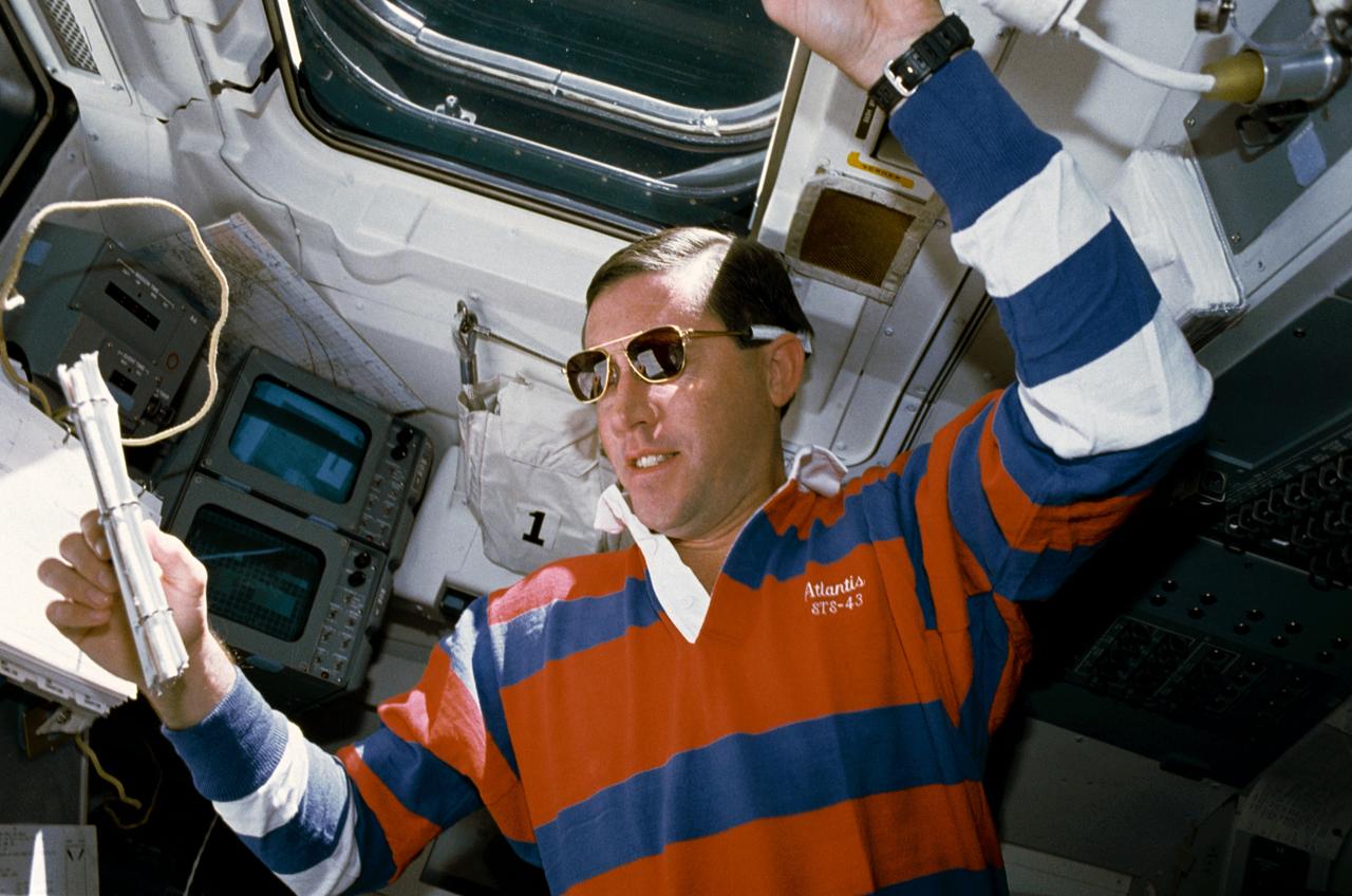
STS043-04-032 (11 Aug 1991) --- STS-43 Pilot Michael A. Baker, wearing sunglasses, reviews a checklist on the aft flight deck of Atlantis, Orbiter Vehicle (OV) 104. He is monitoring data associated with the Space Station Heat Pipe Advanced Radiator Element II (SHARE-II) located in OV-104's payload bay (PLB) from his position in front of the aft flight deck viewing windows. Behind Baker are the closed circuit television (CCTV) monitors and above his head is overhead window W8.

Legendary characters used the power of mythology to fly through the heavens. About 200 BC, a Greek inventor known as Hero of Alexandria came up with a new invention that depended on the mechanical interaction of heat and water. He invented a rocket-like device called an aeolipile. It used steam for propulsion. Hero mounted a sphere on top of a water kettle. A fire below the kettle turned the water into steam, and the gas traveled through the pipes to the sphere. Two L-shaped tubes on opposite sides of the sphere allowed the gas to escape, and in doing so gave a thrust to the sphere that caused it to rotate.
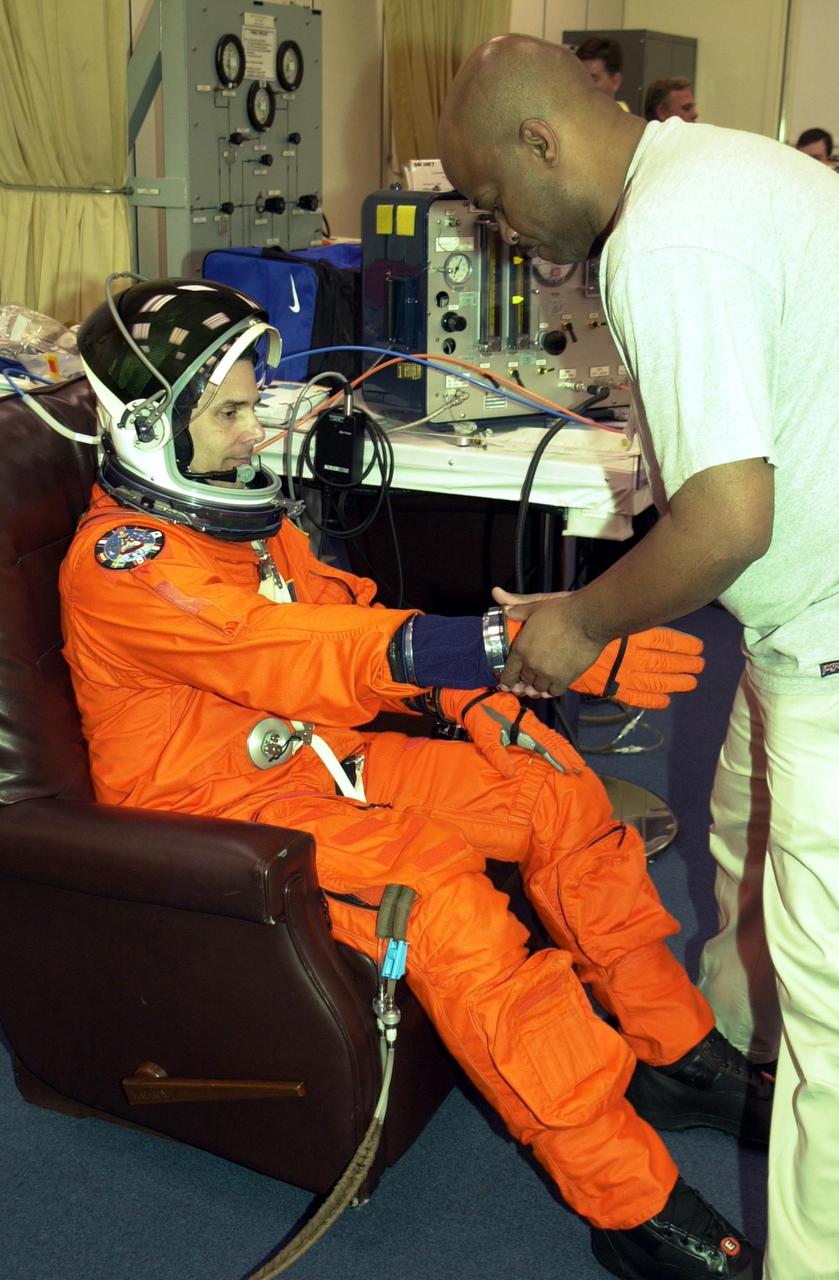
KENNEDY SPACE CENTER, FLA. -- STS-110 Mission Specialist Lee Morin undergoes final check of his launch and entry suit. Morin will be taking his first Shuttle flight. The STS-110 payload includes the S0 Integrated Truss Structure (ITS), the Canadian Mobile Transporter, power distribution system modules, a heat pipe radiator for cooling, computers and a pair of rate gyroscopes. The 11-day mission is the 13th assembly flight to the ISS and includes four spacewalks to attach the S0 truss to the U.S. Lab Destiny. Launch is scheduled for April 4
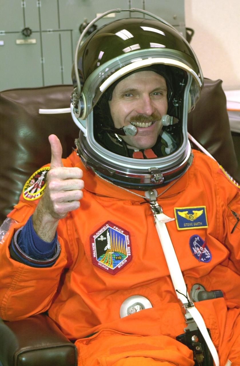
KENNEDY SPACE CENTER, FLA. -- STS-110 Mission Specialist Steven Smith gives a thumbs up for launch as he has a final check of his launch and entry suit. This flight will be his fourth. The STS-110 payload includes the S0 Integrated Truss Structure (ITS), the Canadian Mobile Transporter, power distribution system modules, a heat pipe radiator for cooling, computers and a pair of rate gyroscopes. The 11-day mission is the 13th assembly flight to the ISS and includes four spacewalks to attach the S0 truss to the U.S. Lab Destiny. Launch is scheduled for April 4
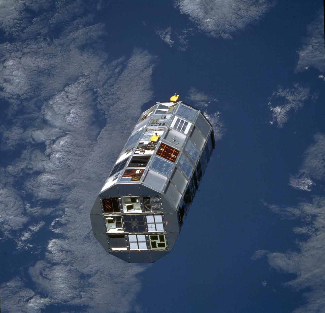
The Long Duration Exposure Facility (LDEF) was designed by the Marshall Space Flight Center (MSFC) to test the performance of spacecraft materials, components, and systems that have been exposed to the environment of micrometeoroids and space debris for an extended period of time. The LDEF proved invaluable to the development of future spacecraft and the International Space Station (ISS). The LDEF carried 57 science and technology experiments, the work of more than 200 investigators. MSFC`s experiments included: Trapped Proton Energy Determination to determine protons trapped in the Earth's magnetic field and the impact of radiation particles; Linear Energy Transfer Spectrum Measurement Experiment which measures the linear energy transfer spectrum behind different shielding configurations; Atomic oxygen-Simulated Out-gassing, an experiment that exposes thermal control surfaces to atomic oxygen to measure the damaging out-gassed products; Thermal Control Surfaces Experiment to determine the effects of the near-Earth orbital environment and the shuttle induced environment on spacecraft thermal control surfaces; Transverse Flat-Plate Heat Pipe Experiment, to evaluate the zero-gravity performance of a number of transverse flat plate heat pipe modules and their ability to transport large quantities of heat; Solar Array Materials Passive LDEF Experiment to examine the effects of space on mechanical, electrical, and optical properties of lightweight solar array materials; and the Effects of Solar Radiation on Glasses. Launched aboard the Space Shuttle Orbiter Challenger's STS-41C mission April 6, 1984, the LDEF remained in orbit for five years until January 1990 when it was retrieved by the Space Shuttle Orbiter Columbia STS-32 mission and brought back to Earth for close examination and analysis.

KENNEDY SPACE CENTER, FLA. -- In the Operations and Checkout Bldg. (O&C), an overhead crane moves the S0 truss segment toward a workstand. The S0 truss will undergo processing in the O&C during which the Canadian Mobile Transporter, power distribution system modules, a heat pipe radiator for cooling, computers, and a pair of rate gyroscopes will be installed. Four Global Positioning System antennas are already installed. A 44by 15-foot structure weighing 30,800 pounds when fully outfitted and ready for launch, the truss will be at the center of the ISS 10-truss, girderlike structure that will ultimately extend the length of a football field. Eventually the S0 truss will be attached to the U.S. Lab, "Destiny," which is scheduled to be added to the ISS in April 2000. Later, other trusses will be attached to the S0 on-orbit. The S0 truss is scheduled to be launched in the first quarter of 2001 on mission STS-108
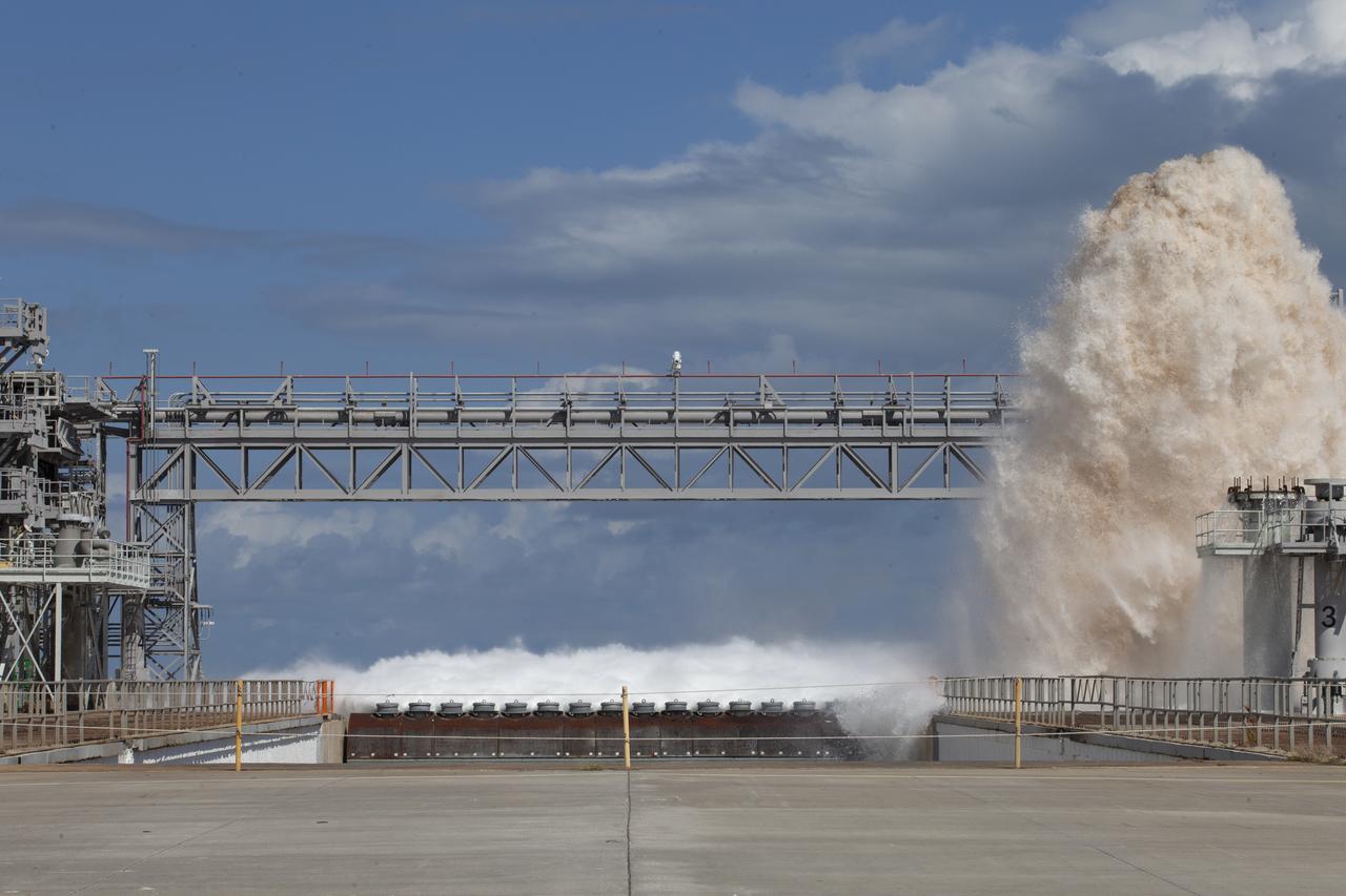
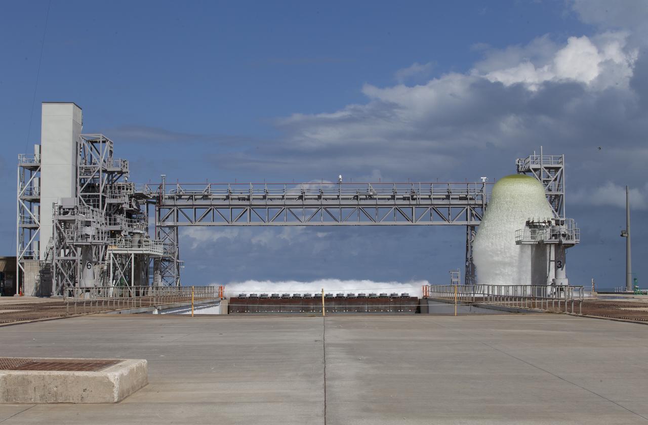
A flow test of the Ignition Overpressure Protection and Sound Suppression water deluge system is in progress at Launch Pad 39B at NASA's Kennedy Space Center in Florida, on Oct. 15, 2018. At peak flow, the water reaches about 100 feet in the air above the pad surface. It flows at high speed from a holding tank through new and modified piping and valves, the flame trench, flame deflector nozzles and mobile launcher interface risers. The testing is part of Exploration Ground System's preparation for the new Space Launch System rocket. Modifications were made to the pad after a previous wet flow test, increasing the performance of the system. During the launch of Exploration Mission-1 and subsequent missions, this water deluge system will release about 450,000 gallons of water across the mobile launcher and Flame Deflector to reduce the extreme heat and energy generated by the rocket during ignition and liftoff.
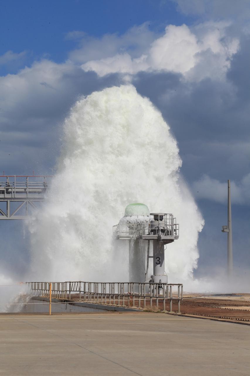
A flow test of the Ignition Overpressure Protection and Sound Suppression water deluge system is in progress at Launch Pad 39B at NASA's Kennedy Space Center in Florida, on Oct. 15, 2018. At peak flow, the water reaches about 100 feet in the air above the pad surface. It flows at high speed from a holding tank through new and modified piping and valves, the flame trench, flame deflector nozzles and mobile launcher interface risers. The testing is part of Exploration Ground System's preparation for the new Space Launch System rocket. Modifications were made to the pad after a previous wet flow test, increasing the performance of the system. During the launch of Exploration Mission-1 and subsequent missions, this water deluge system will release about 450,000 gallons of water across the mobile launcher and Flame Deflector to reduce the extreme heat and energy generated by the rocket during ignition and liftoff.
KENNEDY SPACE CENTER, FLA. -- Inside the Operations and Checkout Bldg. (O&C), an overhead crane is centered over the S0 truss segment before lowering. The crane will move it to a workstand in the O&C where it will undergo processing. In the foreground is the protective cover just removed. During the processing, the Canadian Mobile Transporter, power distribution system modules, a heat pipe radiator for cooling, computers, and a pair of rate gyroscopes will be installed. Four Global Positioning System antennas are already installed. A 44by 15-foot structure weighing 30,800 pounds when fully outfitted and ready for launch, the truss will be at the center of the ISS 10-truss, girderlike structure that will ultimately extend the length of a football field. Eventually the S0 truss will be attached to the U.S. Lab, "Destiny," which is scheduled to be added to the ISS in April 2000. Later, other trusses will be attached to the S0 on-orbit. The S0 truss is scheduled to be launched in the first quarter of 2001 on mission STS-108
KENNEDY SPACE CENTER, FLA. -- Inside the Operations and Checkout Bldg. (O&C), an overhead crane removes the cover from the S0 truss segment beneath it. The S0 truss will undergo processing in the O&C during which the Canadian Mobile Transporter, power distribution system modules, a heat pipe radiator for cooling, computers, and a pair of rate gyroscopes will be installed. Four Global Positioning System antennas are already installed. A 44by 15-foot structure weighing 30,800 pounds when fully outfitted and ready for launch, the truss will be at the center of the ISS 10-truss, girderlike structure that will ultimately extend the length of a football field. Eventually the S0 truss will be attached to the U.S. Lab, "Destiny," which is scheduled to be added to the ISS in April 2000. Later, other trusses will be attached to the S0 on-orbit. The S0 truss is scheduled to be launched in the first quarter of 2001 on mission STS-108
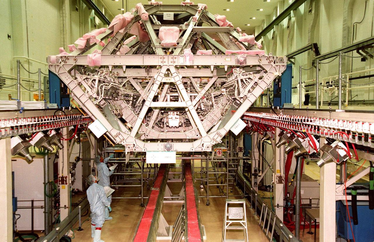
KENNEDY SPACE CENTER, FLA. -- Workers in the Operations & Checkout Bldg. (O&C) look over a central component of the International Space Station (ISS), the S0 (S zero) truss. It is undergoing processing in the O&C during which the Canadian Mobile Transporter, power distribution system modules, a heat pipe radiator for cooling, computers, and a pair of rate gyroscopes are being installed. A 44by 15-foot structure weighing 30,800 pounds when fully outfitted and ready for launch, the truss will ultimately extend the length of a football field. Eventually the S0 truss will be attached to the U.S. Lab, "Destiny," which is scheduled to be added to the ISS in April 2000. Later, other trusses will be attached to the S0 on-orbit. The S0 truss is scheduled to be launched in the spring of 2001
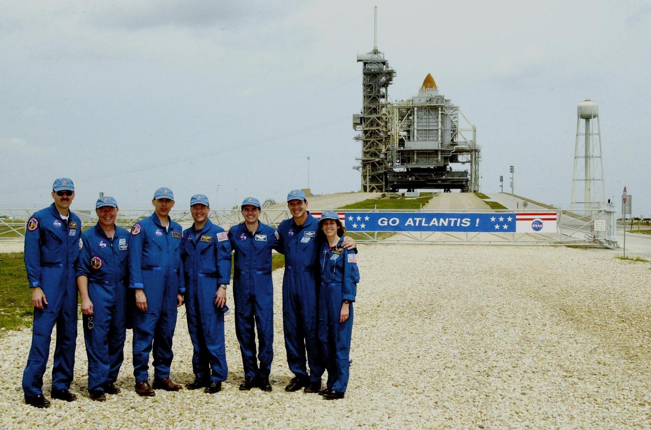
KENNEDY SPACE CENTER, FLA. -- While gathering with friends and family at the pad, the STS-110 crew poses in front of Space Shuttle Atlantis still enclosed by the Rotating Service Structure. Standing left to right are Mission Specialist Steven Smith, Jerry Ross and Lee Morin; Pilot Stephen Frick; Mission Specialist Rex Walheim; Commander Michael Bloomfield; and Mission Specialist Ellen Ochoa. The mission continues the expansion of the International Space Station by delivering and installing the S0 Integrated Truss Structure, the initial section of a framework that will eventually hold the power and cooling systems needed for future international research laboratories. The payload also comprises the Canadian Mobile Transporter (attached to the S0 truss), power distribution system modules, a heat pipe radiator for cooling, computers and a pair of rate gyroscopes. The 11-day mission is the 13th assembly flight to the ISS and includes four spacewalks to attach the S0 truss to the U.S. Lab Destiny. Launch is scheduled for April 4
KENNEDY SPACE CENTER, FLA. -- Workers in the O&C Bldg. watch as the S0 truss is lowered onto a workstand. The S0 truss will undergo processing in the O&C during which the Canadian Mobile Transporter, power distribution system modules, a heat pipe radiator for cooling, computers, and a pair of rate gyroscopes will be installed. Four Global Positioning System antennas are already installed. A 44by 15-foot structure weighing 30,800 pounds when fully outfitted and ready for launch, the truss will be at the center of the ISS 10-truss, girderlike structure that will ultimately extend the length of a football field. Eventually the S0 truss will be attached to the U.S. Lab, "Destiny," which is scheduled to be added to the ISS in April 2000. Later, other trusses will be attached to the S0 on-orbit. The S0 truss is scheduled to be launched in the first quarter of 2001 on mission STS-108
KENNEDY SPACE CENTER, FLA. -- Inside the Operations and Checkout Bldg. (O&C), workers (at left) watch over the maneuvering of the overhead crane toward the S0 truss segment below it. The S0 truss will undergo processing in the O&C during which the Canadian Mobile Transporter, power distribution system modules, a heat pipe radiator for cooling, computers, and a pair of rate gyroscopes will be installed. Four Global Positioning System antennas are already installed. A 44by 15-foot structure weighing 30,800 pounds when fully outfitted and ready for launch, the truss will be at the center of the ISS 10-truss, girderlike structure that will ultimately extend the length of a football field. Eventually the S0 truss will be attached to the U.S. Lab, "Destiny," which is scheduled to be added to the ISS in April 2000. Later, other trusses will be attached to the S0 on-orbit. The S0 truss is scheduled to be launched in the first quarter of 2001 on mission STS-108
KENNEDY SPACE CENTER, FLA. -- In the Operations and Checkout Bldg. (O&C), an overhead crane moves the S0 truss segment toward a workstand. The S0 truss will undergo processing in the O&C during which the Canadian Mobile Transporter, power distribution system modules, a heat pipe radiator for cooling, computers and a pair of rate gyroscopes will be installed. Four Global Positioning System antennas are already installed. A 44- by 15-foot structure weighing 30,800 pounds when fully outfitted and ready for launch, the truss will be at the center of the ISS 10-truss, girderlike structure that will ultimately extend the length of a football field. Eventually the S0 truss will be attached to the U.S. Lab, "Destiny," which is scheduled to be added to the ISS in April 2000. Later, other trusses will be attached to the S0 on orbit. The S0 truss is scheduled to be launched in the first quarter of 2001 on mission STS-108
KENNEDY SPACE CENTER, FLA. -- The S0 truss nears its resting place in the workstand in the O&C Bldg. (O&C). The S0 truss will undergo processing in the O&C during which the Canadian Mobile Transporter, power distribution system modules, a heat pipe radiator for cooling, computers, and a pair of rate gyroscopes will be installed. Four Global Positioning System antennas are already installed. A 44by 15-foot structure weighing 30,800 pounds when fully outfitted and ready for launch, the truss will be at the center of the ISS 10-truss, girderlike structure that will ultimately extend the length of a football field. Eventually the S0 truss will be attached to the U.S. Lab, "Destiny," which is scheduled to be added to the ISS in April 2000. Later, other trusses will be attached to the S0 on-orbit. The S0 truss is scheduled to be launched in the first quarter of 2001 on mission STS-108

A flow test of the Ignition Overpressure Protection and Sound Suppression water deluge system is in progress at Launch Pad 39B at NASA's Kennedy Space Center in Florida, on Oct. 15, 2018. At peak flow, the water reaches about 100 feet in the air above the pad surface. It flows at high speed from a holding tank through new and modified piping and valves, the flame trench, flame deflector nozzles and mobile launcher interface risers. The testing is part of Exploration Ground System's preparation for the new Space Launch System rocket. Modifications were made to the pad after a previous wet flow test, increasing the performance of the system. During the launch of Exploration Mission-1 and subsequent missions, this water deluge system will release about 450,000 gallons of water across the mobile launcher and Flame Deflector to reduce the extreme heat and energy generated by the rocket during ignition and liftoff.

A flow test of the Ignition Overpressure Protection and Sound Suppression water deluge system is in progress at Launch Pad 39B at NASA's Kennedy Space Center in Florida, on Oct. 15, 2018. At peak flow, the water reaches about 100 feet in the air above the pad surface. It flows at high speed from a holding tank through new and modified piping and valves, the flame trench, flame deflector nozzles and mobile launcher interface risers. The testing is part of Exploration Ground System's preparation for the new Space Launch System rocket. Modifications were made to the pad after a previous wet flow test, increasing the performance of the system. During the launch of Exploration Mission-1 and subsequent missions, this water deluge system will release about 450,000 gallons of water across the mobile launcher and Flame Deflector to reduce the extreme heat and energy generated by the rocket during ignition and liftoff.
A flow test of the Ignition Overpressure Protection and Sound Suppression water deluge system is in progress at Launch Pad 39B at NASA's Kennedy Space Center in Florida, on Oct. 15, 2018. At peak flow, the water will reach about 100 feet in the air above the pad surface. It will flow at high speed from a holding tank through new and modified piping and valves, the flame trench, flame deflector nozzles and mobile launcher interface risers. The testing is part of Exploration Ground System's preparation for the new Space Launch System rocket. Modifications were made to the pad after a previous wet flow test, increasing the performance of the system. During the launch of Exploration Mission-1 and subsequent missions, this water deluge system will release about 450,000 gallons of water across the mobile launcher and Flame Deflector to reduce the extreme heat and energy generated by the rocket during ignition and liftoff.

A flow test of the Ignition Overpressure Protection and Sound Suppression water deluge system is in progress at Launch Pad 39B at NASA's Kennedy Space Center in Florida, on Oct. 15, 2018. At peak flow, the water reaches about 100 feet in the air above the pad surface. It flows at high speed from a holding tank through new and modified piping and valves, the flame trench, flame deflector nozzles and mobile launcher interface risers. The testing is part of Exploration Ground System's preparation for the new Space Launch System rocket. Modifications were made to the pad after a previous wet flow test, increasing the performance of the system. During the launch of Exploration Mission-1 and subsequent missions, this water deluge system will release about 450,000 gallons of water across the mobile launcher and Flame Deflector to reduce the extreme heat and energy generated by the rocket during ignition and liftoff.

A flow test of the Ignition Overpressure Protection and Sound Suppression water deluge system is in progress at Launch Pad 39B at NASA's Kennedy Space Center in Florida, on Oct. 15, 2018. At peak flow, the water reaches about 100 feet in the air above the pad surface. It flows at high speed from a holding tank through new and modified piping and valves, the flame trench, flame deflector nozzles and mobile launcher interface risers. The testing is part of Exploration Ground System's preparation for the new Space Launch System rocket. Modifications were made to the pad after a previous wet flow test, increasing the performance of the system. During the launch of Exploration Mission-1 and subsequent missions, this water deluge system will release about 450,000 gallons of water across the mobile launcher and Flame Deflector to reduce the extreme heat and energy generated by the rocket during ignition and liftoff.
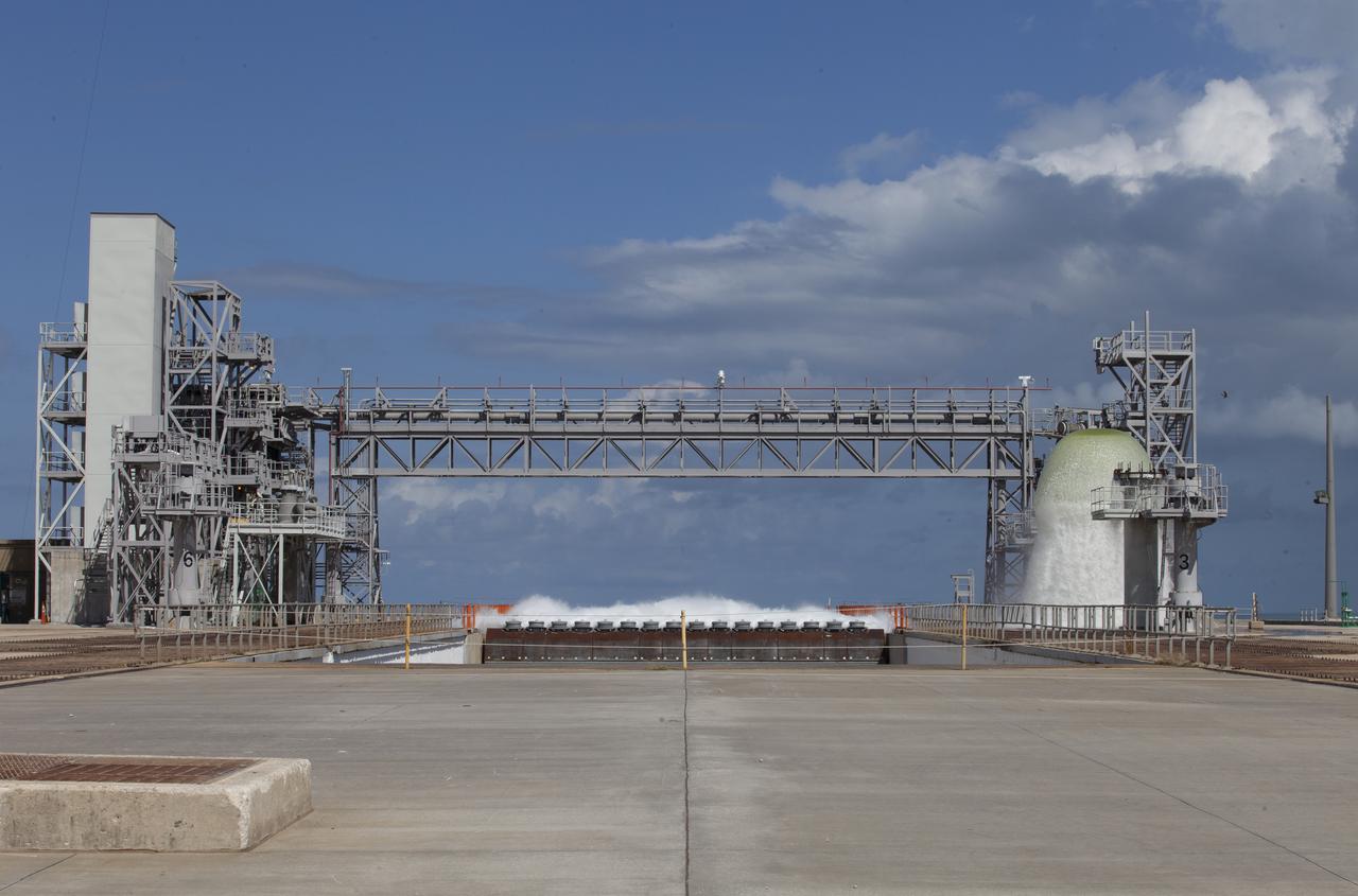
A flow test of the Ignition Overpressure Protection and Sound Suppression water deluge system begins at Launch Pad 39B at NASA's Kennedy Space Center in Florida, on Oct. 15, 2018. At peak flow, the water will reach about 100 feet in the air above the pad surface. It will flow at high speed from a holding tank through new and modified piping and valves, the flame trench, flame deflector nozzles and mobile launcher interface risers. The testing is part of Exploration Ground System's preparation for the new Space Launch System rocket. Modifications were made to the pad after a previous wet flow test, increasing the performance of the system. During the launch of Exploration Mission-1 and subsequent missions, this water deluge system will release about 450,000 gallons of water across the mobile launcher and Flame Deflector to reduce the extreme heat and energy generated by the rocket during ignition and liftoff.
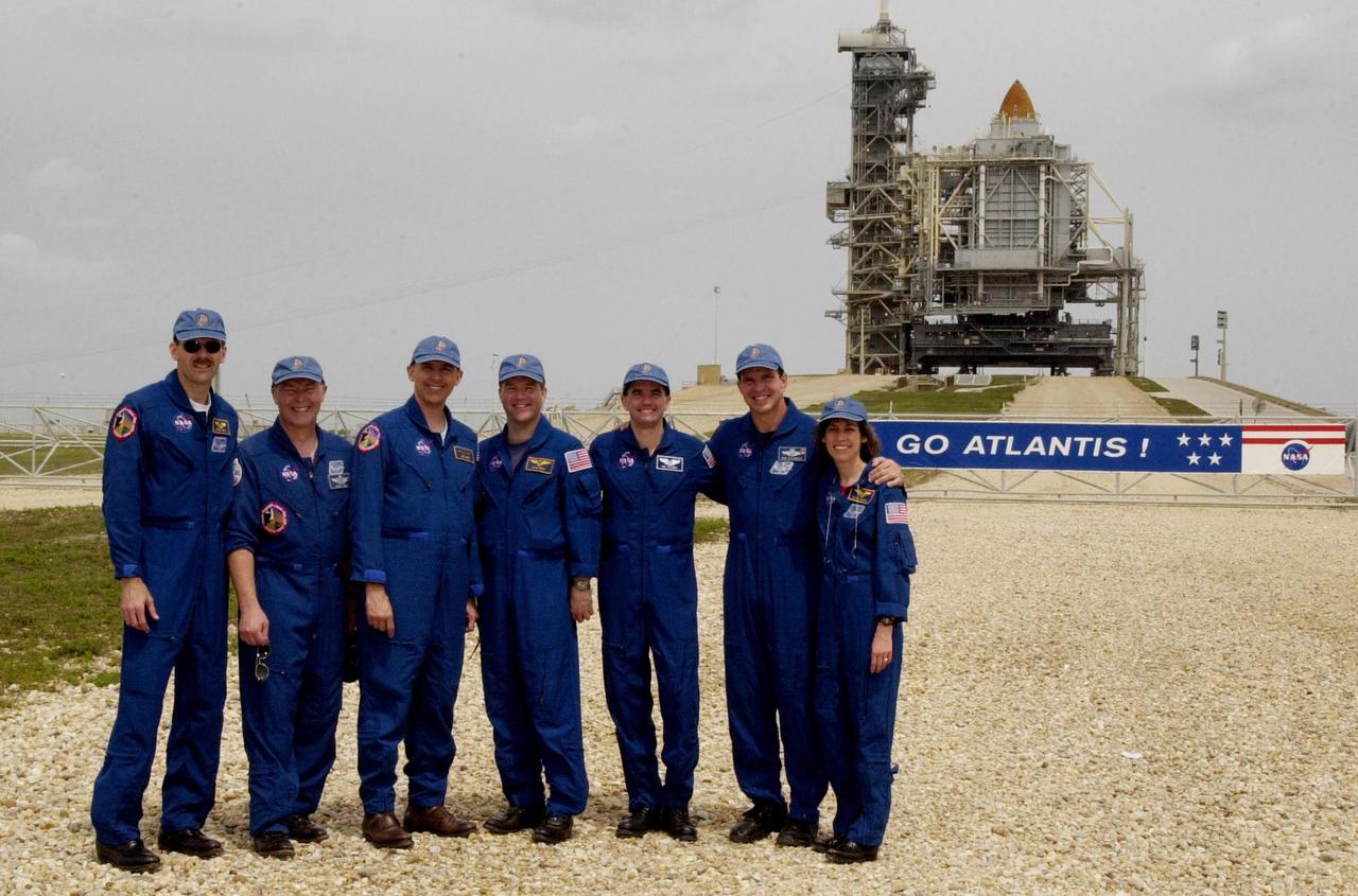
KENNEDY SPACE CENTER, FLA. -- While gathering with friends and family at the pad, the STS-110 crew poses in front of Space Shuttle Atlantis still enclosed by the Rotating Service Structure. Standing left to right are Mission Specialist Steven Smith, Jerry Ross and Lee Morin; Pilot Stephen Frick; Mission Specialist Rex Walheim; Commander Michael Bloomfield; and Mission Specialist Ellen Ochoa. The mission continues the expansion of the International Space Station by delivering and installing the S0 Integrated Truss Structure, the initial section of a framework that will eventually hold the power and cooling systems needed for future international research laboratories. The payload also comprises the Canadian Mobile Transporter (attached to the S0 truss), power distribution system modules, a heat pipe radiator for cooling, computers and a pair of rate gyroscopes. The 11-day mission is the 13th assembly flight to the ISS and includes four spacewalks to attach the S0 truss to the U.S. Lab Destiny. Launch is scheduled for April 4
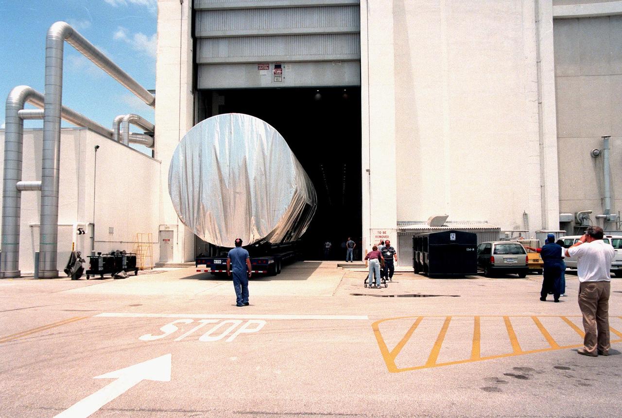
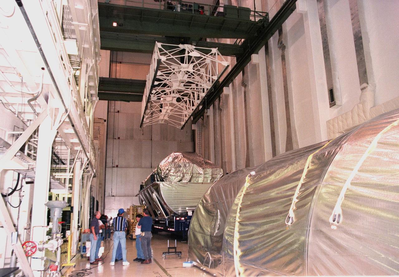
KENNEDY SPACE CENTER, FLA. -- The S0 truss segment is moved into the Operations and Checkout Bldg. (O&C) for processing. The truss arrived at the SLF aboard a "Super Guppy" aircraft from Boeing in Huntington, Calif. During processing in the O&C, the S0 truss will have installed the Canadian Mobile Transporter, power distribution system modules, a heat pipe radiator for cooling, computers, and a pair of rate gyroscopes. Four Global Positioning System antennas are already installed. A 44by 15-foot structure weighing 30,800 pounds when fully outfitted and ready for launch, the truss will be at the center of the ISS 10-truss, girderlike structure that will ultimately extend the length of a football field. Eventually the S0 truss will be attached to the U.S. Lab, "Destiny," which is scheduled to be added to the ISS in April 2000. Later, other trusses will be attached to the S0 on-orbit. The S0 truss is scheduled to be launched in the first quarter of 2001 on mission STS-108
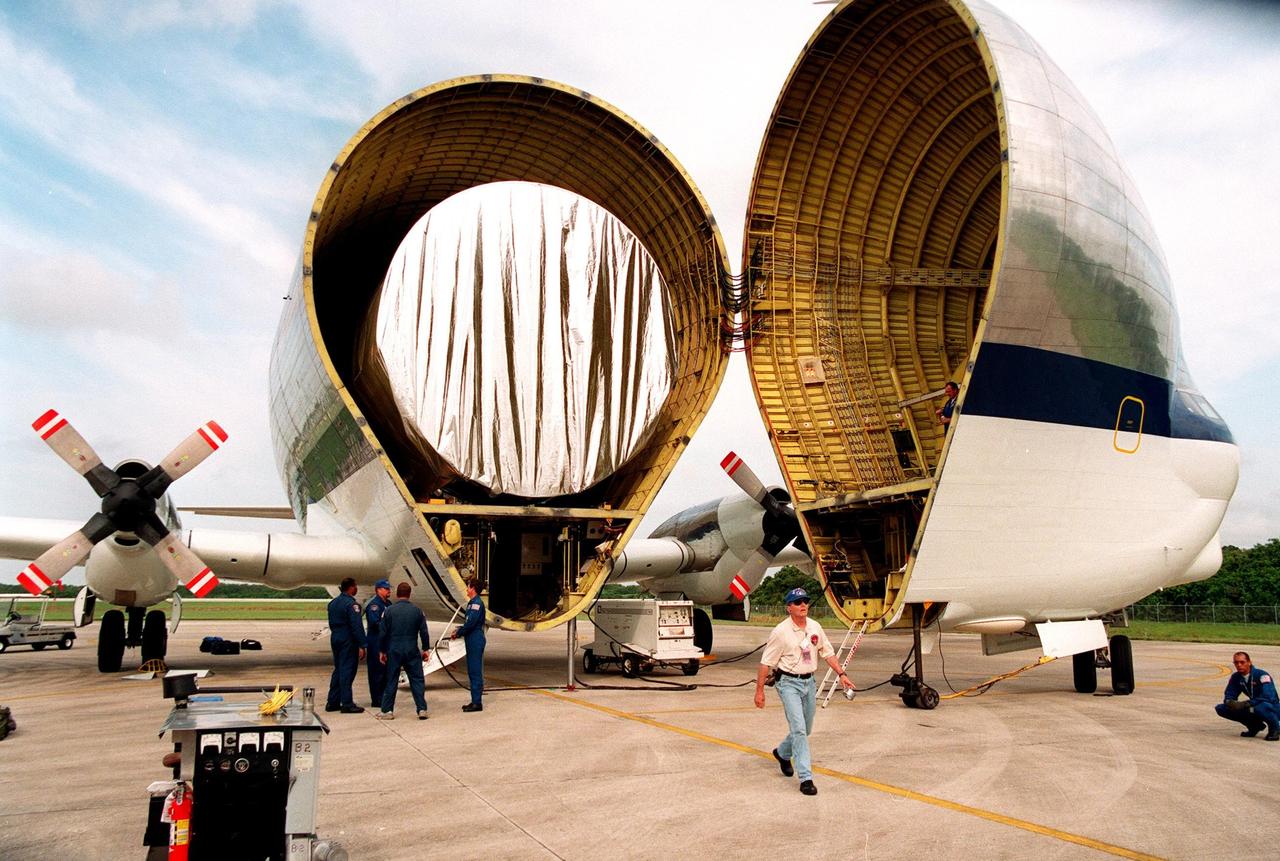
KENNEDY SPACE CENTER, FLA. -- After landing at KSC's Shuttle Landing Facility, the "Super Guppy" transport aircraft opens to reveal its cargo, a S0 (S Zero) truss segment, from Boeing in Huntington Beach, Calif. The truss segment, which will become the backbone of the orbiting International Space Station (ISS), is a 44by 15-foot structure weighing 30,800 pounds when fully outfitted and ready for launch. It will be at the center of the ISS 10-truss, girderlike structure that will ultimately extend the length of a football field. Eventually the S0 truss will be attached to the U.S. Lab, "Destiny," which is scheduled to be added to the ISS in April 2000. Later, other trusses will be attached to the S0 on-orbit. During processing at KSC, the S0 truss will have installed the Canadian Mobile Transporter, power distribution system modules, a heat pipe radiator for cooling, computers, and a pair of rate gyroscopes. Four Global Positioning System antennas are already installed. The S0 truss is scheduled to be launched in the first quarter of 2001 on mission STS-108
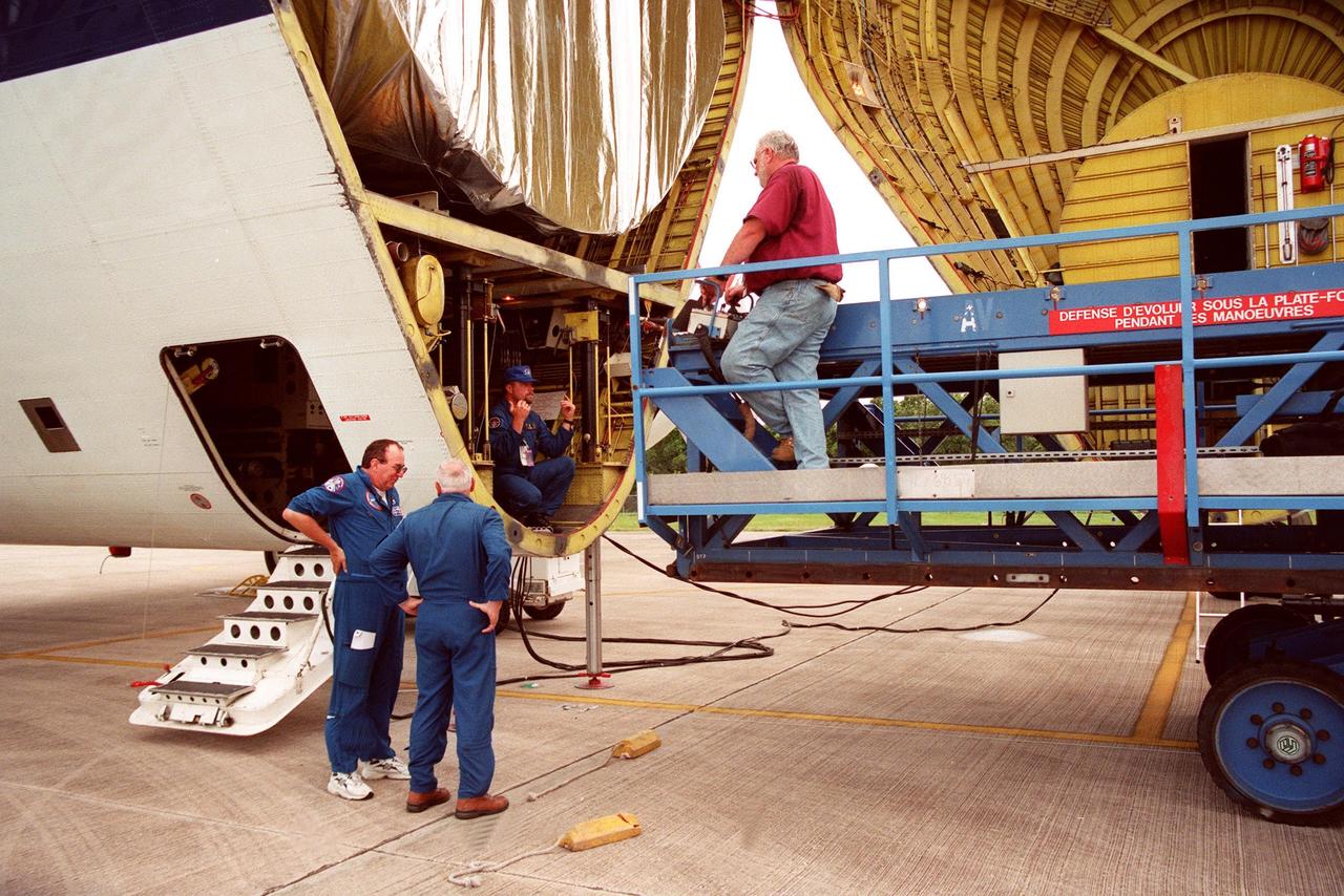
KENNEDY SPACE CENTER, Fla. - A transporter (right) is moved into place to remove a S0 (S Zero) truss segment (left) from inside the "Super Guppy" aircraft that brought it to KSC from Boeing in Huntington Beach, Calif. The truss segment, which will become the backbone of the orbiting International Space Station (ISS), is a 44- by 15-foot structure weighing 30,800 pounds when fully outfitted and ready for launch. It will be at the center of the ISS 10-truss, girderlike structure that will ultimately extend the length of a football field. Eventually the S0 truss will be attached to the U.S. Lab, "Destiny," which is scheduled to be added to the ISS in April 2000. Later, other trusses will be attached to the S0 on-orbit. During processing at KSC, the S0 truss will have installed the Canadian Mobile Transporter, power distribution system modules, a heat pipe radiator for cooling, computers, and a pair of rate gyroscopes. Four Global Positioning System antennas are already installed. The S0 truss is scheduled to be launched in the first quarter of 2001 on mission STS-108
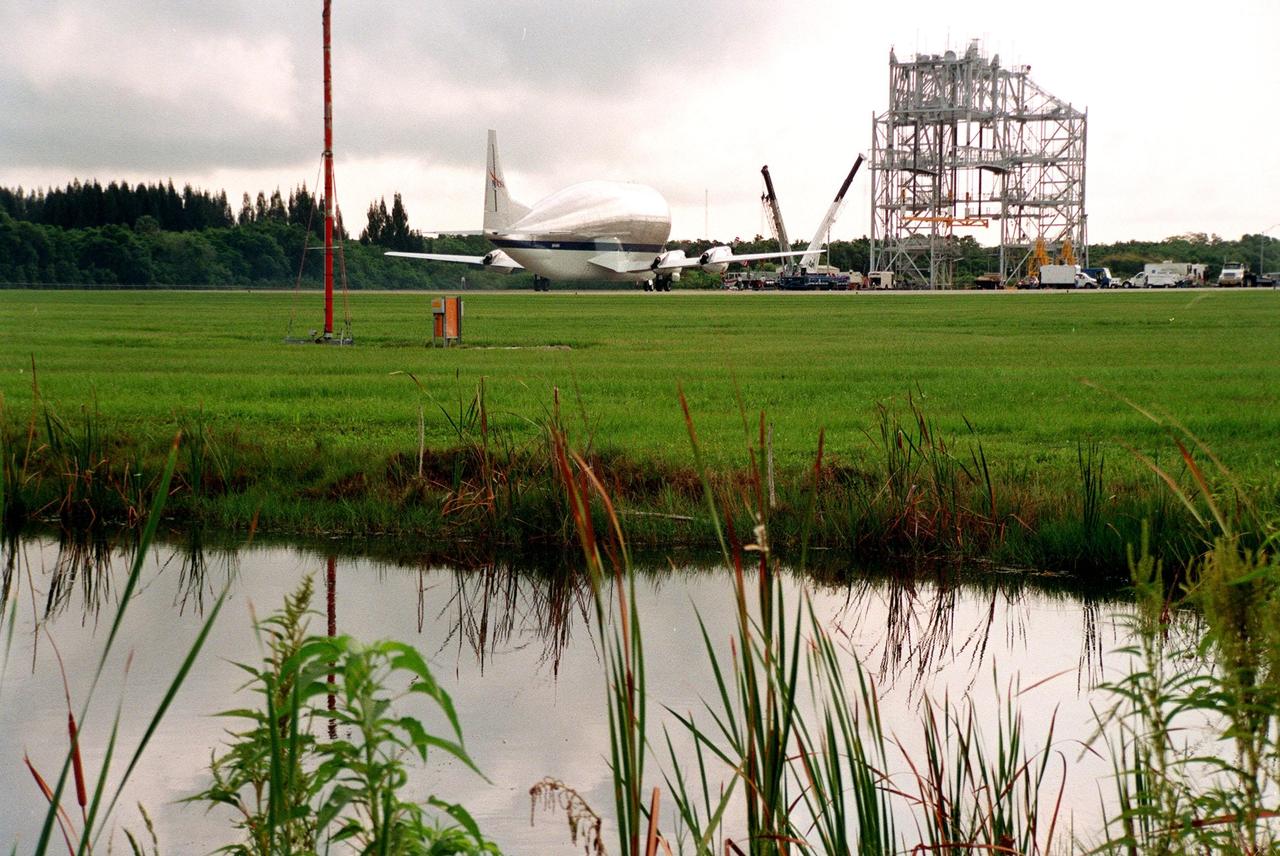
KENNEDY SPACE CENTER, FLA. -- At KSC's Shuttle Landing Facility, the "Super Guppy" transport aircraft touches down on the runway. On board the aircraft is the S0 (S Zero) truss segment, from Boeing in Huntington Beach, Calif. The truss segment, which will become the backbone of the orbiting International Space Station (ISS), is a 44by 15-foot structure weighing 30,800 pounds when fully outfitted and ready for launch. It will be at the center of the ISS 10-truss, girderlike structure that will ultimately extend the length of a football field. Eventually the S0 truss will be attached to the U.S. Lab, "Destiny," which is scheduled to be added to the ISS in April 2000. Later, other trusses will be attached to the S0 on-orbit. During processing at KSC, the S0 truss will have installed the Canadian Mobile Transporter, power distribution system modules, a heat pipe radiator for cooling, computers, and a pair of rate gyroscopes. Four Global Positioning System antennas are already installed. The S0 truss is scheduled to be launched in the first quarter of 2001 on mission STS-108
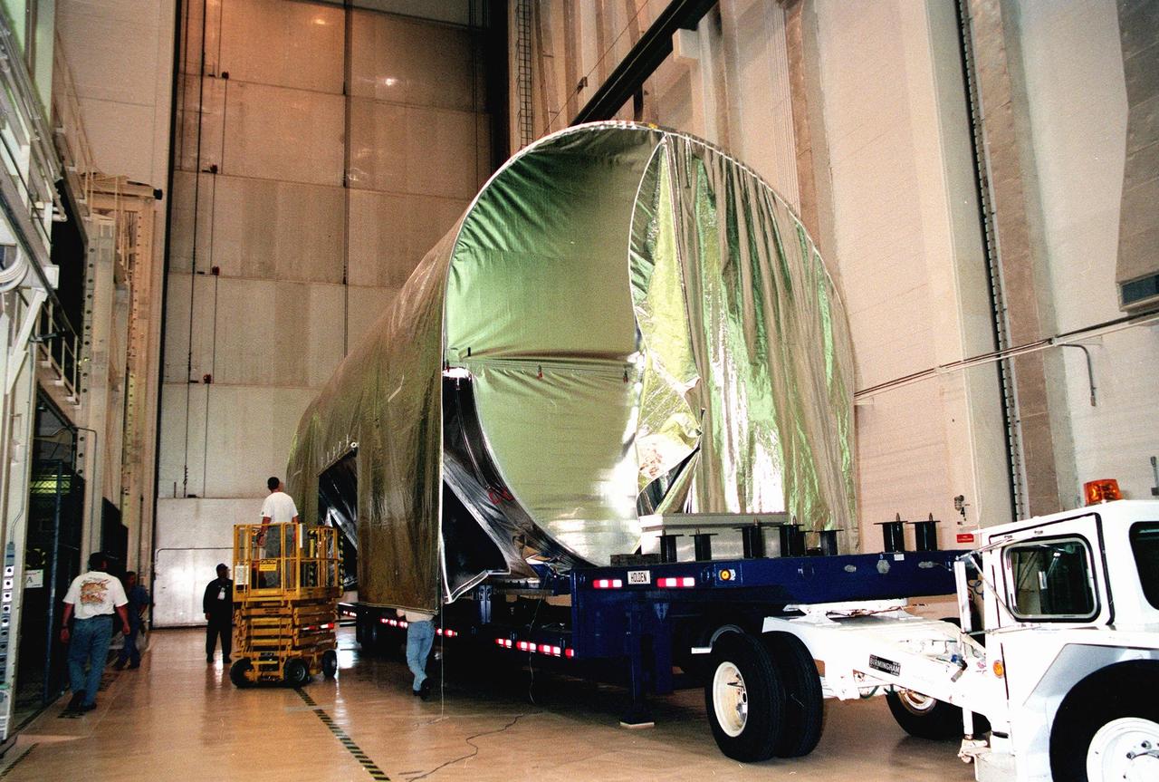
KENNEDY SPACE CENTER, FLA. -- Workers begin removing the cover from the S0 truss segment after it was moved inside the Operations and Checkout Bldg. (O&C) for processing. The truss arrived at the SLF aboard a "Super Guppy" aircraft from Boeing in Huntington, Calif. During processing in the O&C, the S0 truss will have installed the Canadian Mobile Transporter, power distribution system modules, a heat pipe radiator for cooling, computers, and a pair of rate gyroscopes. Four Global Positioning System antennas are already installed. A 44by 15-foot structure weighing 30,800 pounds when fully outfitted and ready for launch, the truss will be at the center of the ISS 10-truss, girderlike structure that will ultimately extend the length of a football field. Eventually the S0 truss will be attached to the U.S. Lab, "Destiny," which is scheduled to be added to the ISS in April 2000. Later, other trusses will be attached to the S0 on-orbit. The S0 truss is scheduled to be launched in the first quarter of 2001 on mission STS-108
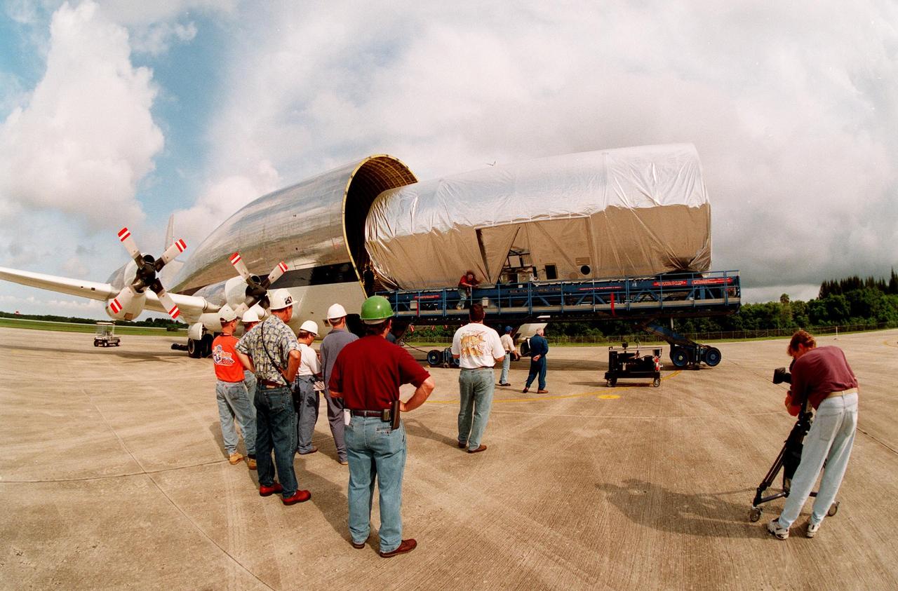
KENNEDY SPACE CENTER, FLA. -- At KSC's Shuttle Landing Facility, workers watch as a S0 (S Zero) truss segment built for the International Space Station (ISS) is moved out of the "Super Guppy" aircraft that brought it to KSC from Boeing in Huntington Beach, Calif. At right a cameraman records the exercise. The truss segment, which will become the backbone of the orbiting ISS, is a 44by 15-foot structure weighing 30,800 pounds when fully outfitted and ready for launch. It will be at the center of the ISS 10-truss, girderlike structure that will ultimately extend the length of a football field. Eventually the S0 truss will be attached to the U.S. Lab, "Destiny," which is scheduled to be added to the ISS in April 2000. Later, other trusses will be attached to the S0 on-orbit. During processing at KSC, the Canadian Mobile Transporter will be installed on the S0 truss, followed by power distribution system modules, a heat pipe radiator for cooling, computers, and a pair of rate gyroscopes. Four Global Positioning System antennas are already installed. The S0 truss is scheduled to be launched in the first quarter of 2001 on mission STS-108
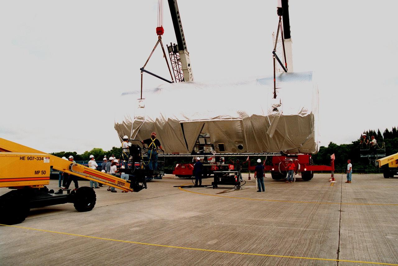
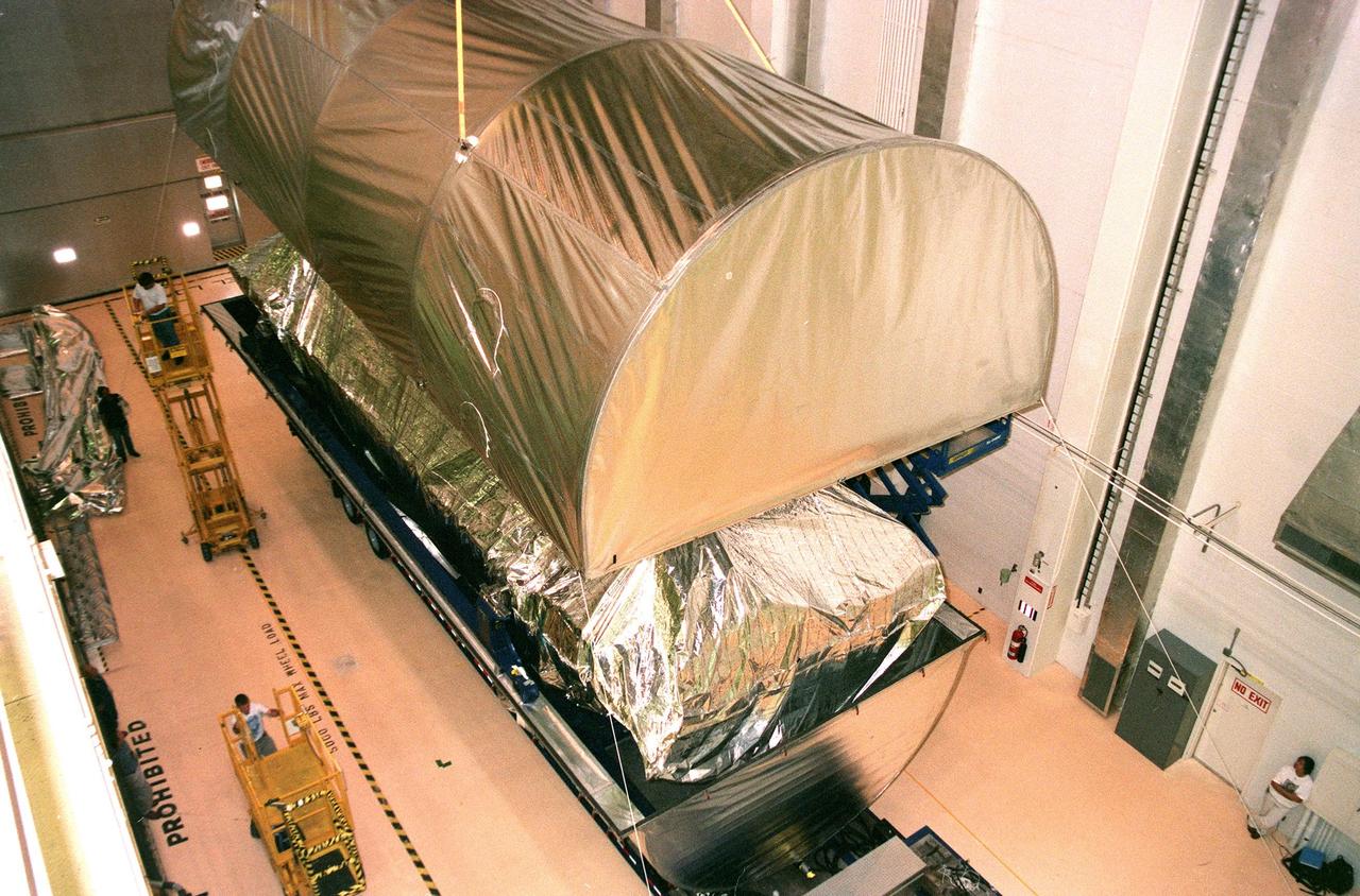
KENNEDY SPACE CENTER, FLA. -- At KSC's Shuttle Landing Facility, workers load the S0 truss segment onto a flatbed trailer for its transfer to the Operations and Checkout Bldg. for processing. The truss arrived at the SLF aboard a "Super Guppy" aircraft from Boeing in Huntington, Calif. During processing in the O&C, the S0 truss will have installed the Canadian Mobile Transporter, power distribution system modules, a heat pipe radiator for cooling, computers, and a pair of rate gyroscopes. Four Global Positioning System antennas are already installed. A 44by 15-foot structure weighing 30,800 pounds when fully outfitted and ready for launch, the truss will be at the center of the ISS 10-truss, girderlike structure that will ultimately extend the length of a football field. Eventually the S0 truss will be attached to the U.S. Lab, "Destiny," which is scheduled to be added to the ISS in April 2000. Later, other trusses will be attached to the S0 on-orbit. The S0 truss is scheduled to be launched in the first quarter of 2001 on mission STS-108
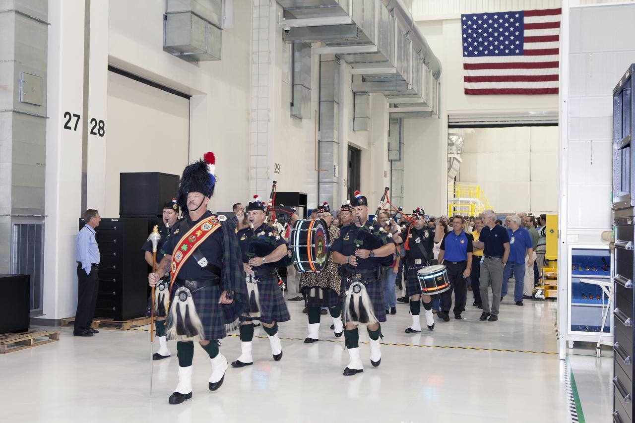
CAPE CANAVERAL, Fla. – Inside the Neil Armstrong Operations and Checkout Building high bay at NASA's Kennedy Space Center in Florida, members of the Brevard Police and Fire Pipes and Drums lead NASA and Lockheed Martin workers toward the Orion crew module, stacked atop its service module. A ceremony will begin to officially turn over the Orion spacecraft for Exploration Flight Test-1 to Lockheed Martin Ground Operations from Orion Assembly, Integration and Production. Orion is the exploration spacecraft designed to carry astronauts to destinations not yet explored by humans, including an asteroid and Mars. It will have emergency abort capability, sustain the crew during space travel and provide safe re-entry from deep space return velocities. The first unpiloted test flight of the Orion is scheduled to launch atop a United Launch Alliance Delta IV Heavy rocket from Cape Canaveral Air Force Station in Florida in December to an altitude of 3,600 miles above the Earth's surface. The two-orbit, four-hour flight test will help engineers evaluate the systems critical to crew safety including the heat shield, parachute system and launch abort system. For more information, visit http://www.nasa.gov/orion. Photo credit: NASA/Daniel Casper
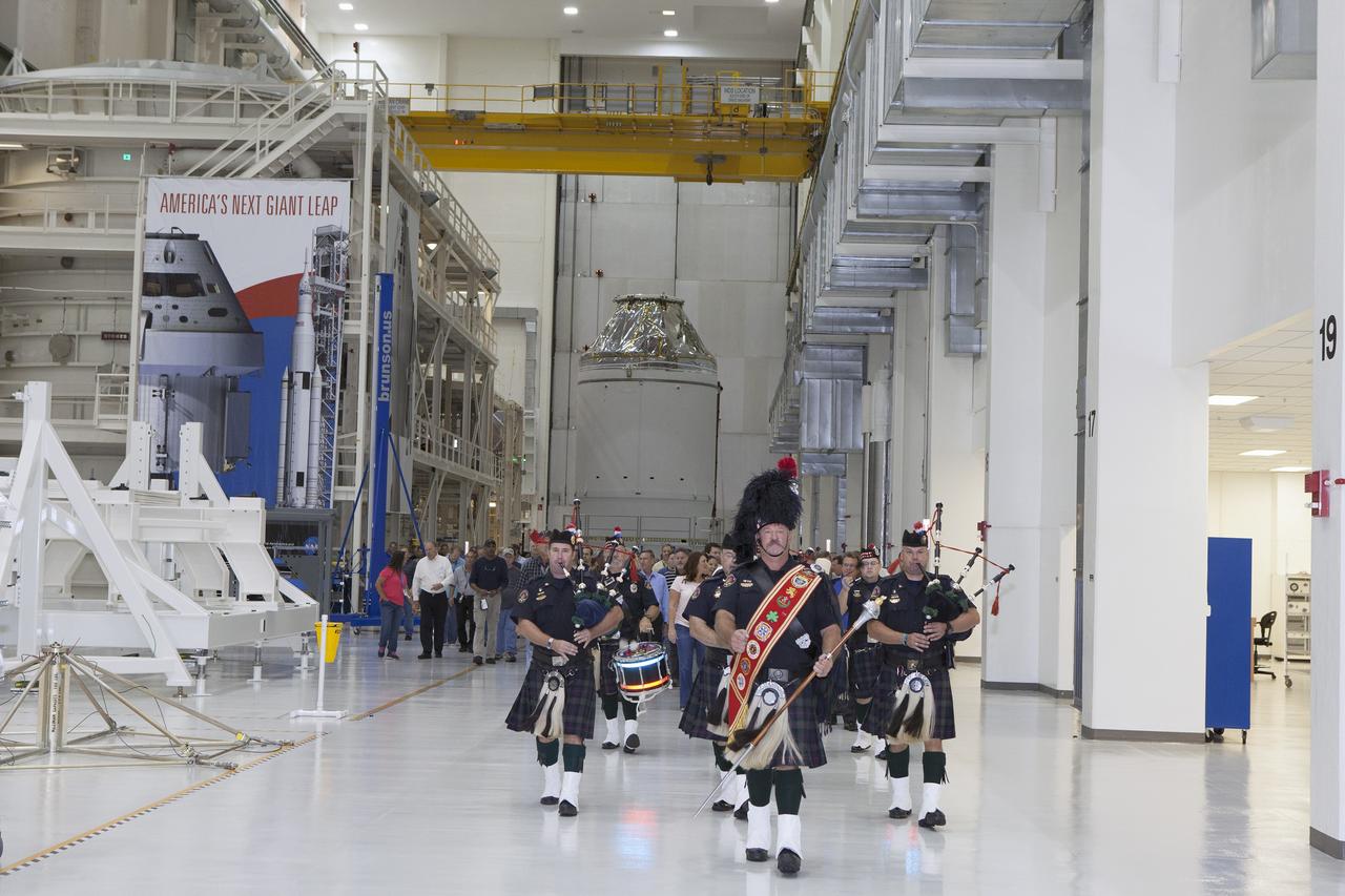
CAPE CANAVERAL, Fla. – Inside the Neil Armstrong Operations and Checkout Building high bay at NASA's Kennedy Space Center in Florida, members of the Brevard Police and Fire Pipes and Drums lead NASA and Lockheed Martin workers out of the high bay after a ceremony to turn over the Orion spacecraft for Exploration Flight Test-1 to Lockheed Martin Ground Operations from Orion Assembly, Integration and Production. Orion is the exploration spacecraft designed to carry astronauts to destinations not yet explored by humans, including an asteroid and Mars. It will have emergency abort capability, sustain the crew during space travel and provide safe re-entry from deep space return velocities. The first unpiloted test flight of the Orion is scheduled to launch atop a United Launch Alliance Delta IV Heavy rocket from Cape Canaveral Air Force Station in Florida in December to an altitude of 3,600 miles above the Earth's surface. The two-orbit, four-hour flight test will help engineers evaluate the systems critical to crew safety including the heat shield, parachute system and launch abort system. For more information, visit http://www.nasa.gov/orion. Photo credit: NASA/Daniel Casper
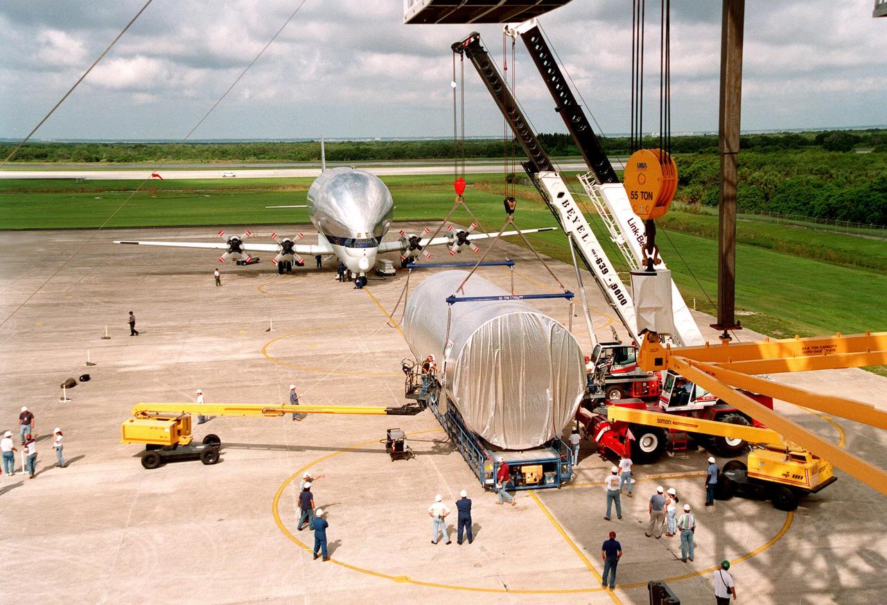
KENNEDY SPACE CENTER, FLA. -- At KSC's Shuttle Landing Facility (SLF), overhead cranes are fitted around the S0 truss segment to move it onto a flatbed trailer which will transfer it to the Operations and Checkout Bldg. for processing. The truss arrived at the SLF aboard the "Super Guppy" aircraft (in the background) from Boeing in Huntington, Calif. During processing, the Canadian Mobile Transporter will be installed on the S0 truss, followed by power distribution system modules, a heat pipe radiator for cooling, computers, and a pair of rate gyroscopes. Four Global Positioning System antennas are already installed. A 44by 15-foot structure weighing 30,800 pounds when fully outfitted and ready for launch, the truss will be at the center of the ISS 10-truss, girderlike structure that will ultimately extend the length of a football field. Eventually the S0 truss will be attached to the U.S. Lab, "Destiny," which is scheduled to be added to the ISS in April 2000. Later, other trusses will be attached to the S0 on-orbit. The S0 truss is scheduled to be launched in the first quarter of 2001 on mission STS-108
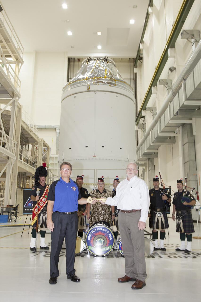
CAPE CANAVERAL, Fla. – During a ceremony inside the Neil Armstrong Operations and Checkout Building high bay at NASA's Kennedy Space Center in Florida, the Orion spacecraft for Exploration Flight Test-1 was officially turned over to Lockheed Martin Ground Operations from Orion Assembly, Integration and Production. Holding the key during the turn over, are Jules Schneider, at left, Lockheed Martin Orion Production Operations manager, and Blake Hale, Lockheed Martin Ground Operations manager. Behind them are members of the Brevard Police and Fire Pipes and Drums. Orion is the exploration spacecraft designed to carry astronauts to destinations not yet explored by humans, including an asteroid and Mars. It will have emergency abort capability, sustain the crew during space travel and provide safe re-entry from deep space return velocities. The first unpiloted test flight of the Orion is scheduled to launch atop a United Launch Alliance Delta IV Heavy rocket from Cape Canaveral Air Force Station in Florida in December to an altitude of 3,600 miles above the Earth's surface. The two-orbit, four-hour flight test will help engineers evaluate the systems critical to crew safety including the heat shield, parachute system and launch abort system. For more information, visit http://www.nasa.gov/orion. Photo credit: NASA/Daniel Casper
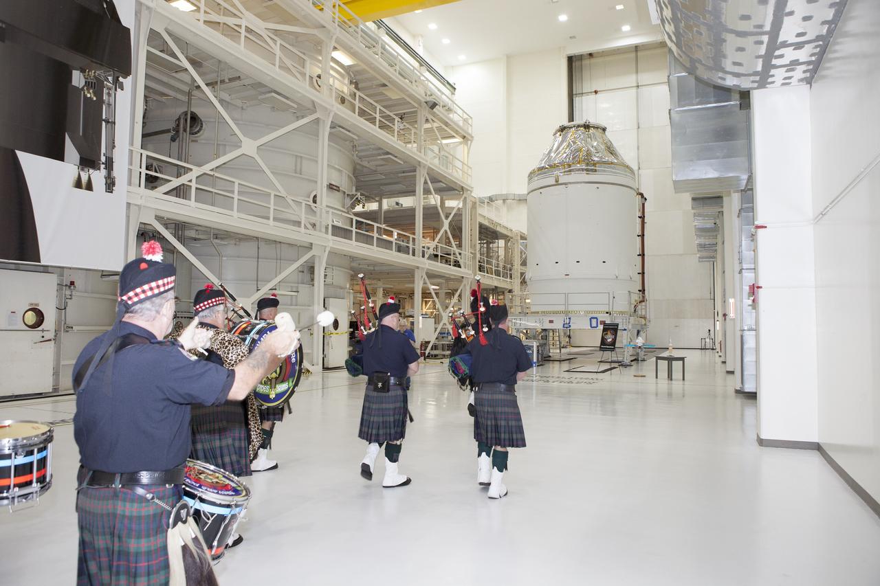
CAPE CANAVERAL, Fla. – Inside the Neil Armstrong Operations and Checkout Building high bay at NASA's Kennedy Space Center in Florida, members of the Brevard Police and Fire Pipes and Drums lead NASA and Lockheed Martin workers toward the Orion crew module, stacked atop its service module. A ceremony will begin to officially turn over the Orion spacecraft for Exploration Flight Test-1 to Lockheed Martin Ground Operations from Orion Assembly, Integration and Production. Orion is the exploration spacecraft designed to carry astronauts to destinations not yet explored by humans, including an asteroid and Mars. It will have emergency abort capability, sustain the crew during space travel and provide safe re-entry from deep space return velocities. The first unpiloted test flight of the Orion is scheduled to launch atop a United Launch Alliance Delta IV Heavy rocket from Cape Canaveral Air Force Station in Florida in December to an altitude of 3,600 miles above the Earth's surface. The two-orbit, four-hour flight test will help engineers evaluate the systems critical to crew safety including the heat shield, parachute system and launch abort system. For more information, visit http://www.nasa.gov/orion. Photo credit: NASA/Daniel Casper
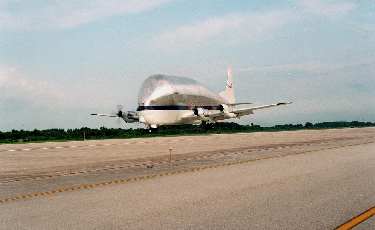
KENNEDY SPACE CENTER, FLA. -- The "Super Guppy" transport aircraft approaches the runway at the KSC's Shuttle Landing Facility. On board is the S0 (S Zero) truss segment, from Boeing in Huntington Beach, Calif. The truss segment, which will become the backbone of the orbiting International Space Station (ISS), is a 44- by 15-foot structure weighing 30,800 pounds when fully outfitted and ready for launch. It will be at the center of the 10-truss, girderlike structure that will ultimately extend the length of a football field on the ISS. Eventually the S0 truss will be attached to the U.S. Lab, "Destiny," scheduled to be added to the ISS in April 2000. Later, other trusses will be attached to the S0 truss on-orbit. During processing at KSC, the S0 truss will have installed the Canadian Mobile Transporter, power distribution system modules, a heat pipe radiator for cooling, computers, and a pair of rate gyroscopes. Four Global Positioning System antennas are already installed. The S0 truss is scheduled to be launched in the first quarter of 2001 on mission STS-108

KENNEDY SPACE CENTER, FLA. -- At KSC's Shuttle Landing Facility, workers finish loading the S0 truss segment onto a flatbed trailer for transfer to the Operations and Checkout Bldg. for processing. The truss arrived at the SLF aboard a "Super Guppy" aircraft from Boeing in Huntington, Calif. During processing in the O&C, the S0 truss will have installed the Canadian Mobile Transporter, power distribution system modules, a heat pipe radiator for cooling, computers, and a pair of rate gyroscopes. Four Global Positioning System antennas are already installed. A 44by 15-foot structure weighing 30,800 pounds when fully outfitted and ready for launch, the truss will be at the center of the ISS 10-truss, girderlike structure that will ultimately extend the length of a football field. Eventually the S0 truss will be attached to the U.S. Lab, "Destiny," which is scheduled to be added to the ISS in April 2000. Later, other trusses will be attached to the S0 on-orbit. The S0 truss is scheduled to be launched in the first quarter of 2001 on mission STS-108
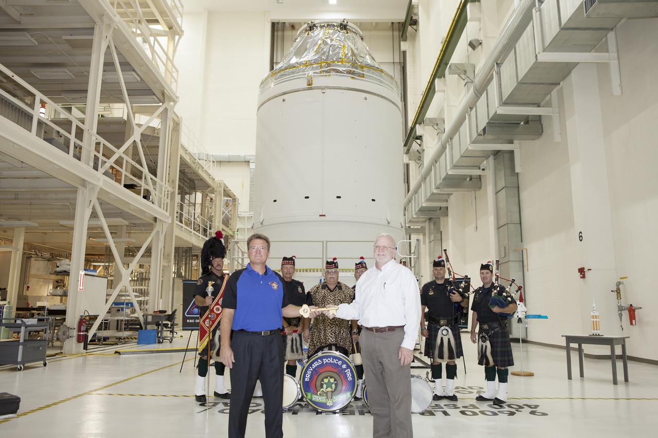
CAPE CANAVERAL, Fla. – During a ceremony inside the Neil Armstrong Operations and Checkout Building high bay at NASA's Kennedy Space Center in Florida, the Orion spacecraft for Exploration Flight Test-1 was officially turned over to Lockheed Martin Ground Operations from Orion Assembly, Integration and Production. Shaking hands during the turn over, are Jules Schneider, at left, Lockheed Martin Orion Production Operations manager, and Blake Hale, Lockheed Martin Ground Operations manager. Behind them are members of the Brevard Police and Fire Pipes and Drums. Orion is the exploration spacecraft designed to carry astronauts to destinations not yet explored by humans, including an asteroid and Mars. It will have emergency abort capability, sustain the crew during space travel and provide safe re-entry from deep space return velocities. The first unpiloted test flight of the Orion is scheduled to launch atop a United Launch Alliance Delta IV Heavy rocket from Cape Canaveral Air Force Station in Florida in December to an altitude of 3,600 miles above the Earth's surface. The two-orbit, four-hour flight test will help engineers evaluate the systems critical to crew safety including the heat shield, parachute system and launch abort system. For more information, visit http://www.nasa.gov/orion. Photo credit: NASA/Daniel Casper
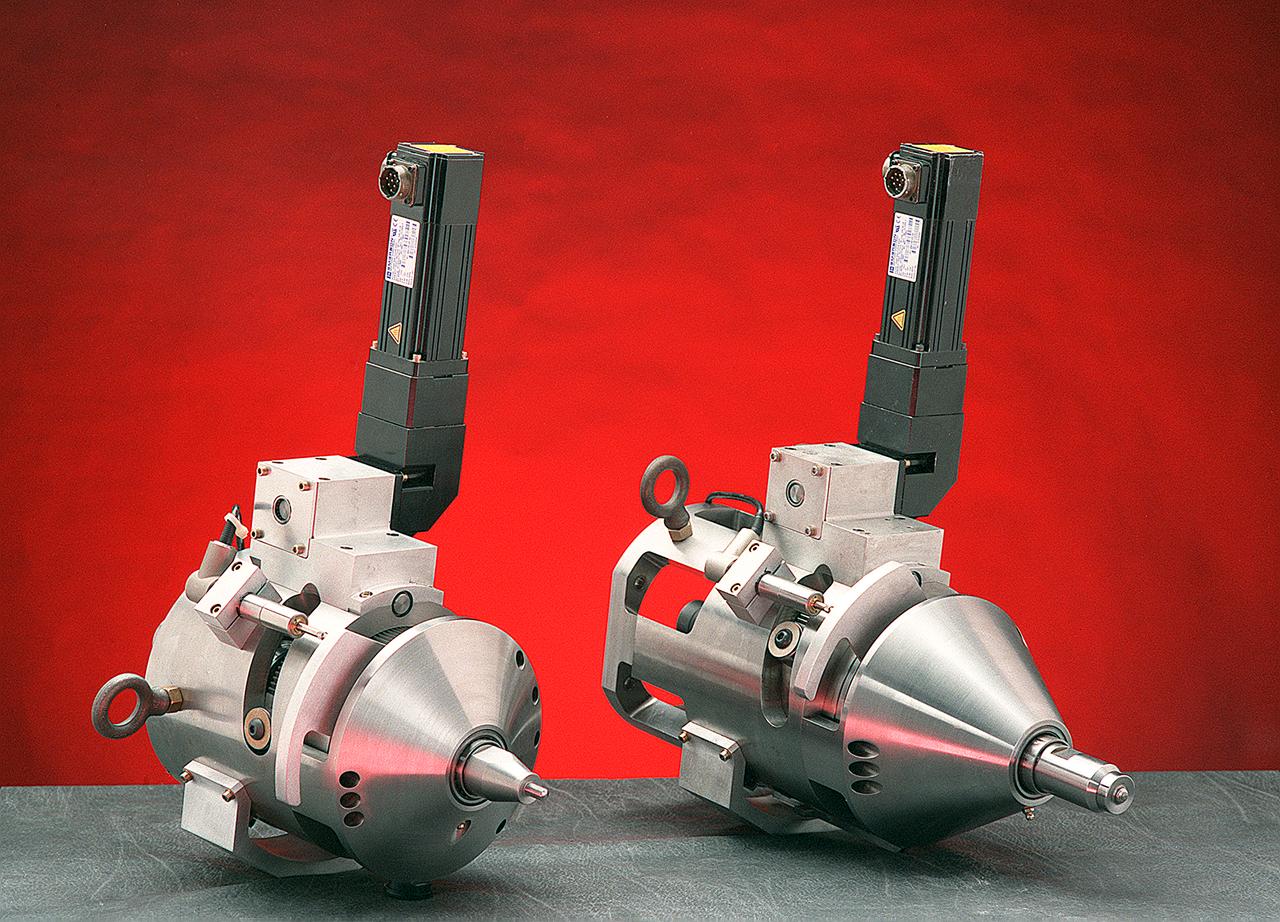
Two companies have successfully commercialized a specialized welding tool developed at the Marshall Space Flight Center (MSFC). Friction stir welding uses the high rotational speed of a tool and the resulting frictional heat created from contact to crush, "stir" together, and forge a bond between two metal alloys. It has had a major drawback, reliance on a single-piece pin tool. The pin is slowly plunged into the joint between two materials to be welded and rotated as high speed. At the end of the weld, the single-piece pin tool is retracted and leaves a "keyhole," something which is unacceptable when welding cylindrical objects such as drums, pipes and storage tanks. Another drawback is the requirement for different-length pin tools when welding materials of varying thickness. An engineer at the MSFC helped design an automatic retractable pin tool that uses a computer-controlled motor to automatically retract the pin into the shoulder of the tool at the end of the weld, preventing keyholes. This design allows the pin angle and length to be adjusted for changes in material thickness and results in a smooth hole closure at the end of the weld. Benefits of friction stir welding, using the MSFC retractable pin tool technology, include the following: The ability to weld a wide range of alloys, including previously unweldable and composite materials; provision of twice the fatigue resistance of fusion welds and no keyholes; minimization of material distortion; no creation of hazards such as welding fumes, radiation, high voltage, liquid metals, or arcing; automatic retraction of the pin at the end of the weld; and maintaining full penetration of the pin.
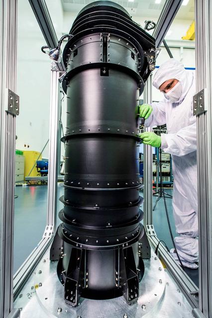
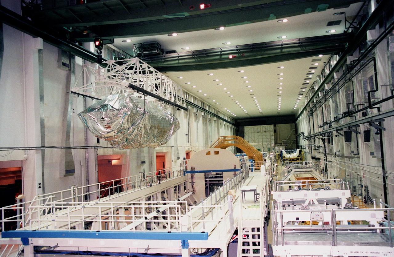
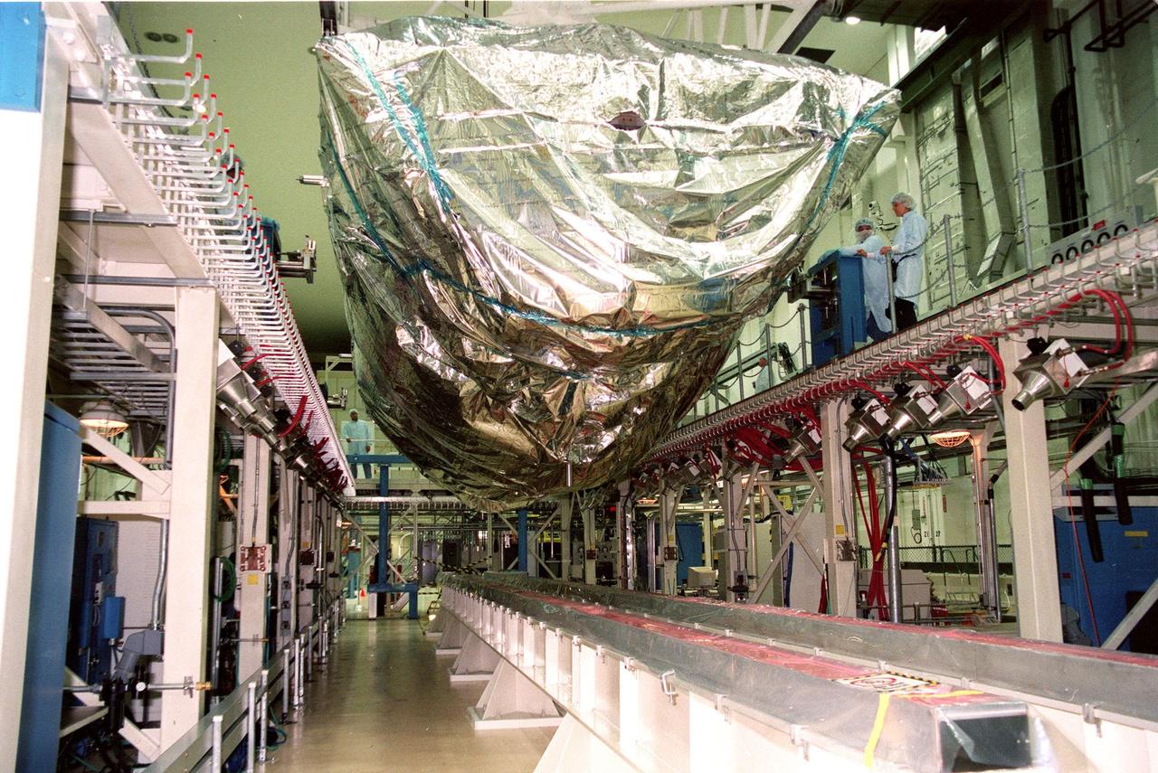
Building a space telescope to see the light from the earliest stars of our universe is a pretty complex task. Although much of the attention goes to instruments and the giant mirrors on NASA's James Webb Space Telescope, there are other components that have big jobs to do and that required imagination, engineering, and innovation to become a reality. For example, engineers working on the Webb telescope have to think of everything from keeping instruments from overheating or freezing, to packing up the Webb, which is as big as a tennis court, to fit inside the rocket that will take it to space. Those are two areas where the "DTA" or Deployable Tower Assembly (DTA) plays a major role. The DTA looks like a big black pipe and is made out of graphite-epoxy composite material to ensure stability and strength with extreme changes in temperature like those encountered in space. When fully deployed, the DTA reaches ten feet in length. The DTA interfaces and supports the spacecraft and the telescope structures. It features two large nested telescoping tubes, connected by a mechanized lead screw. It is a deployable structure that is both very light and extremely strong and stable. The Webb telescope’s secondary mirror support structure and DTA contribute to how the telescope and instruments fit into the rocket fairing in preparation for launch. The DTA allows the Webb to be short enough when stowed to fit in the rocket fairing with an acceptably low center of gravity for launch. Several days after the Webb telescope is launched, the DTA will deploy, or separate, the telescope mirrors and instruments from the spacecraft bus and sunshield. This separation allows the sunshield to unfurl and shade the telescope and instruments from radiant heat and stray light from the sun and Earth. The DTA was designed, built and tested by Astro Aerospace - a Northrop Grumman Company, in Carpinteria, California. The James Webb Space Telescope is the scientific successor to NASA's Hubble Space Telescope. It will be the most powerful space telescope ever built. The Webb telescope is an international project led by NASA with its partners, the European Space Agency and the Canadian Space Agency. For more information about the Webb telescope, visit: <a href="http://www.nasa.gov/webb" rel="nofollow">www.nasa.gov/webb</a> or jwst.nasa.gov <b><a href="http://www.nasa.gov/audience/formedia/features/MP_Photo_Guidelines.html" rel="nofollow">NASA image use policy.</a></b> <b><a href="http://www.nasa.gov/centers/goddard/home/index.html" rel="nofollow">NASA Goddard Space Flight Center</a></b> enables NASA’s mission through four scientific endeavors: Earth Science, Heliophysics, Solar System Exploration, and Astrophysics. Goddard plays a leading role in NASA’s accomplishments by contributing compelling scientific knowledge to advance the Agency’s mission. <b>Follow us on <a href="http://twitter.com/NASAGoddardPix" rel="nofollow">Twitter</a></b> <b>Like us on <a href="http://www.facebook.com/pages/Greenbelt-MD/NASA-Goddard/395013845897?ref=tsd" rel="nofollow">Facebook</a></b> <b>Find us on <a href="http://instagrid.me/nasagoddard/?vm=grid" rel="nofollow">Instagram</a></b>