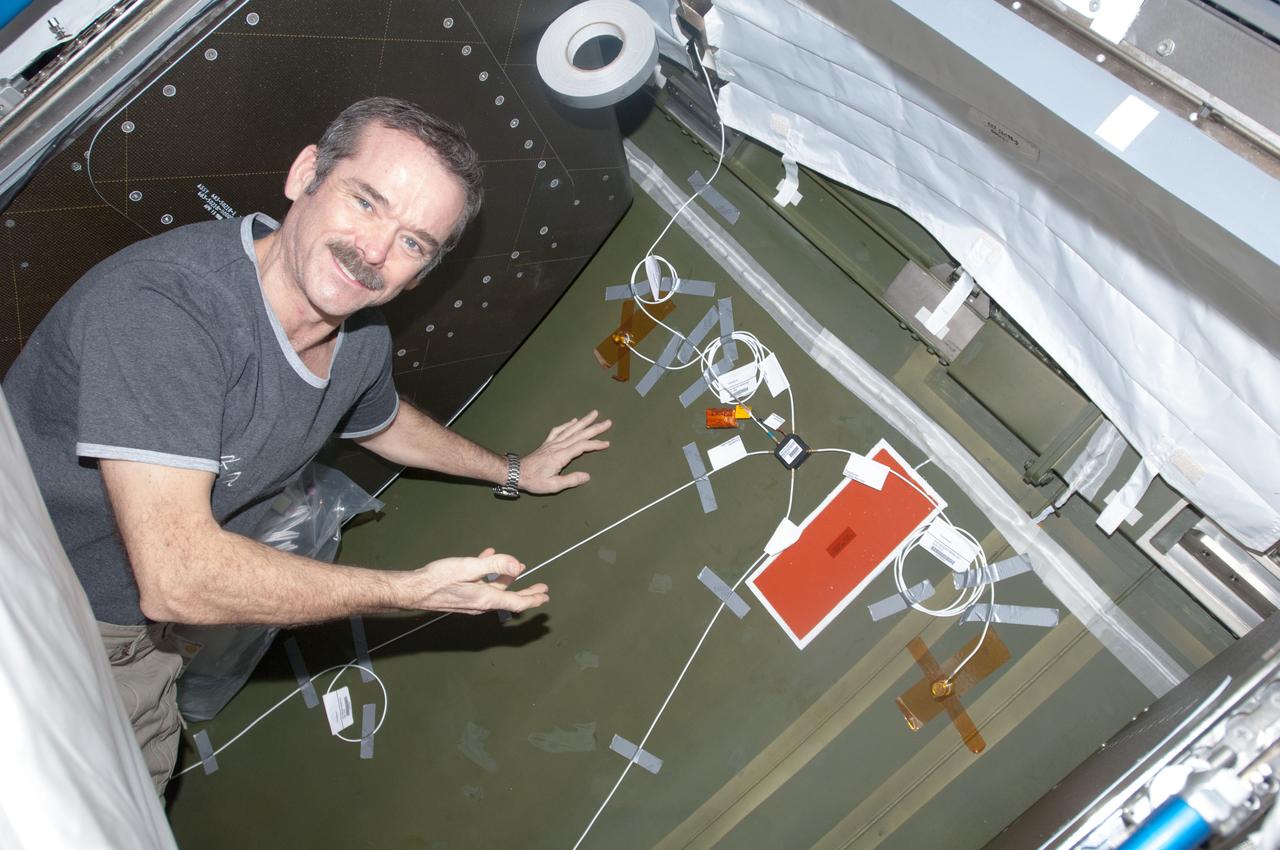
View of Canadian Space Agency (CSA) Chris Hadfield,Expedition 34 Flight Engineer (FE),installing Ultra-Sonic Background Noise Tests (UBNT) sensors behind rack in the U.S. Laboratory using the International Space Station (ISS) as Testbed for Analog Research (ISTAR) procedures. These sensors detect high frequency noise levels generated by ISS hardware and equipment operating within the U.S. Laboratory. Photo was taken during Expedition 34.
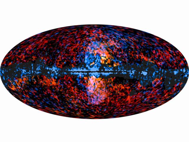
This all-sky image shows the distribution of the galactic haze seen by ESA Planck mission at microwave frequencies superimposed over the high-energy sky, as seen by NASA Fermi Gamma-ray Space Telescope.
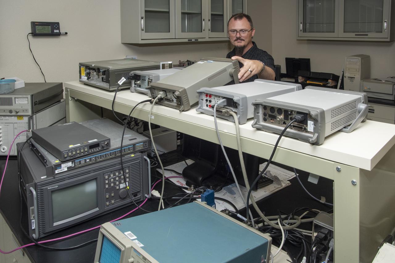
Paul Craig calibrates specialized high-level radio frequency equipment at NASA’s Armstrong Flight Research Center in California.

iss070e027402 (Nov. 17, 2023) --- NASA astronaut and Expedition 70 Flight Engineer Jasmin Moghbeli works in the Harmony module and calibrates an ultrasonic inspection device that uses high-frequency sound waves to analyze materials aboard the International Space Station.
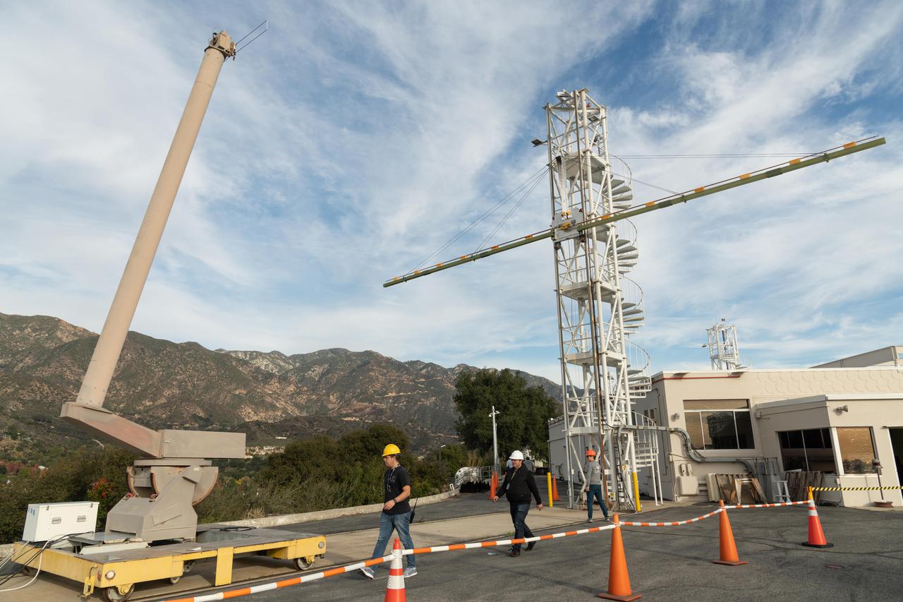
Engineers at NASA's Jet Propulsion Laboratory in Southern California test an engineering model of a high-frequency (HF) radar antenna that makes up part of NASA's Europa Clipper radar instrument on Dec. 17, 2019. The antenna is a 59-foot-long (18-meter-long) narrow copper tube held straight by several cables and a cross bar on the tower at right. In space, the copper tube will stick out straight on its own, but in Earth's gravity, the antenna requires supports to keep it straight for testing. The mobile tower at left holds a model of the VHF (very high-frequency) antenna so that engineers could measure the amount of energy coupled from one antenna to the other. Europa Clipper's radar instrument is called Radar for Europa Assessment and Sounding: Ocean to Near-surface, or REASON. As the spacecraft orbits Jupiter and surveys its icy moon Europa, REASON will use HF and VHF radio signals to penetrate up to 18 miles (30 kilometers) into the icy shell that covers Europa. The radio waves will bounce off subsurface features and return to the spacecraft to create images of the ice layers' internal structure. REASON will help scientists look for the moon's suspected ocean, measure ice thickness, and better understand the icy shell's interior. The instrument will also study the elevation, properties, and roughness of Europa's surface, and will prowl Europa's upper atmosphere for signs of plume activity. The antennae were built for NASA by Heliospace Corporation in Berkeley, California, and the University of Texas at Austin is the lead institution for REASON. The testing was conducted at JPL's Mesa Antenna Measurement Facility, which sits on a high plateau. With an internal global ocean twice the size of Earth's oceans combined, Europa may have the potential to harbor life. The Europa Clipper orbiter will swoop around Jupiter on an elliptical path, dipping close to the moon on each flyby to collect data. Understanding Europa's habitability will help scientists better understand how life developed on Earth and the potential for finding life beyond our planet. Europa Clipper is aiming for a launch readiness date of 2024. https://photojournal.jpl.nasa.gov/catalog/PIA24323
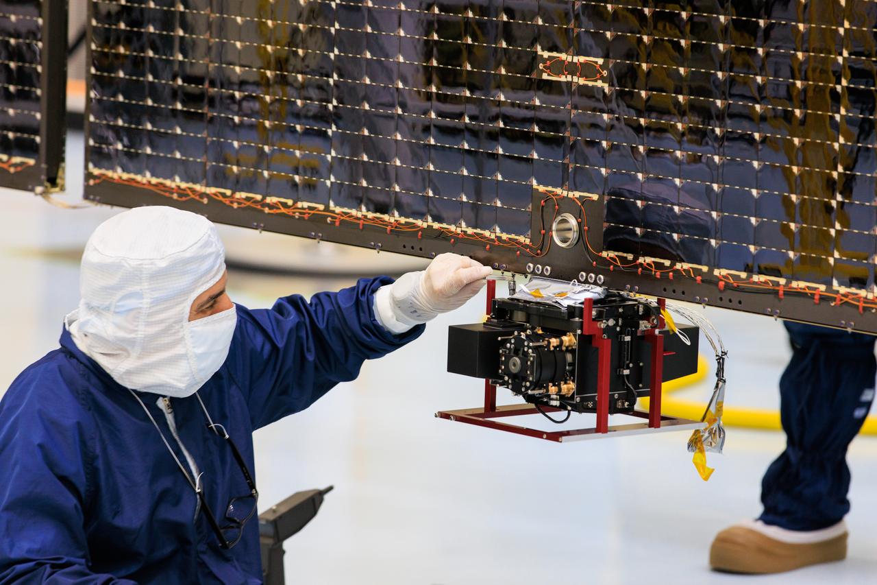
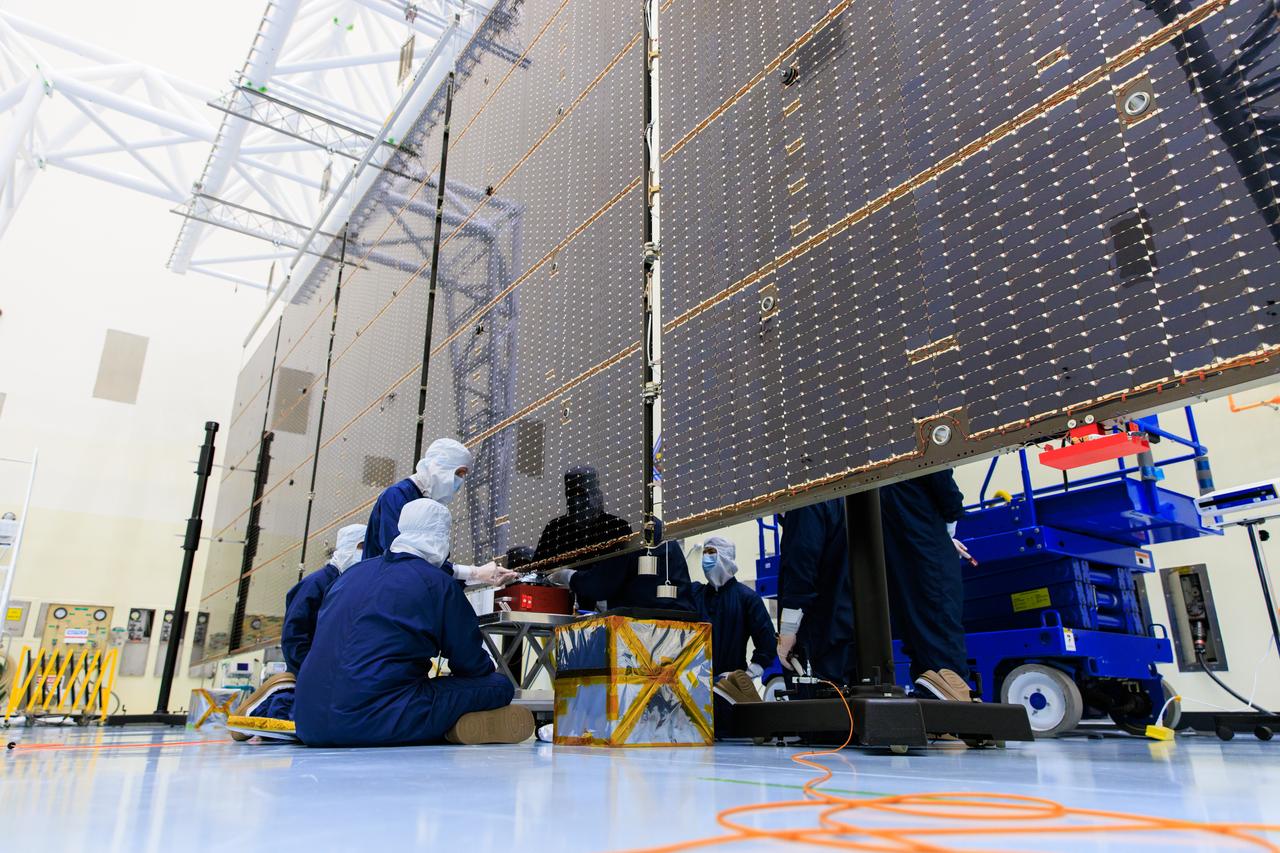
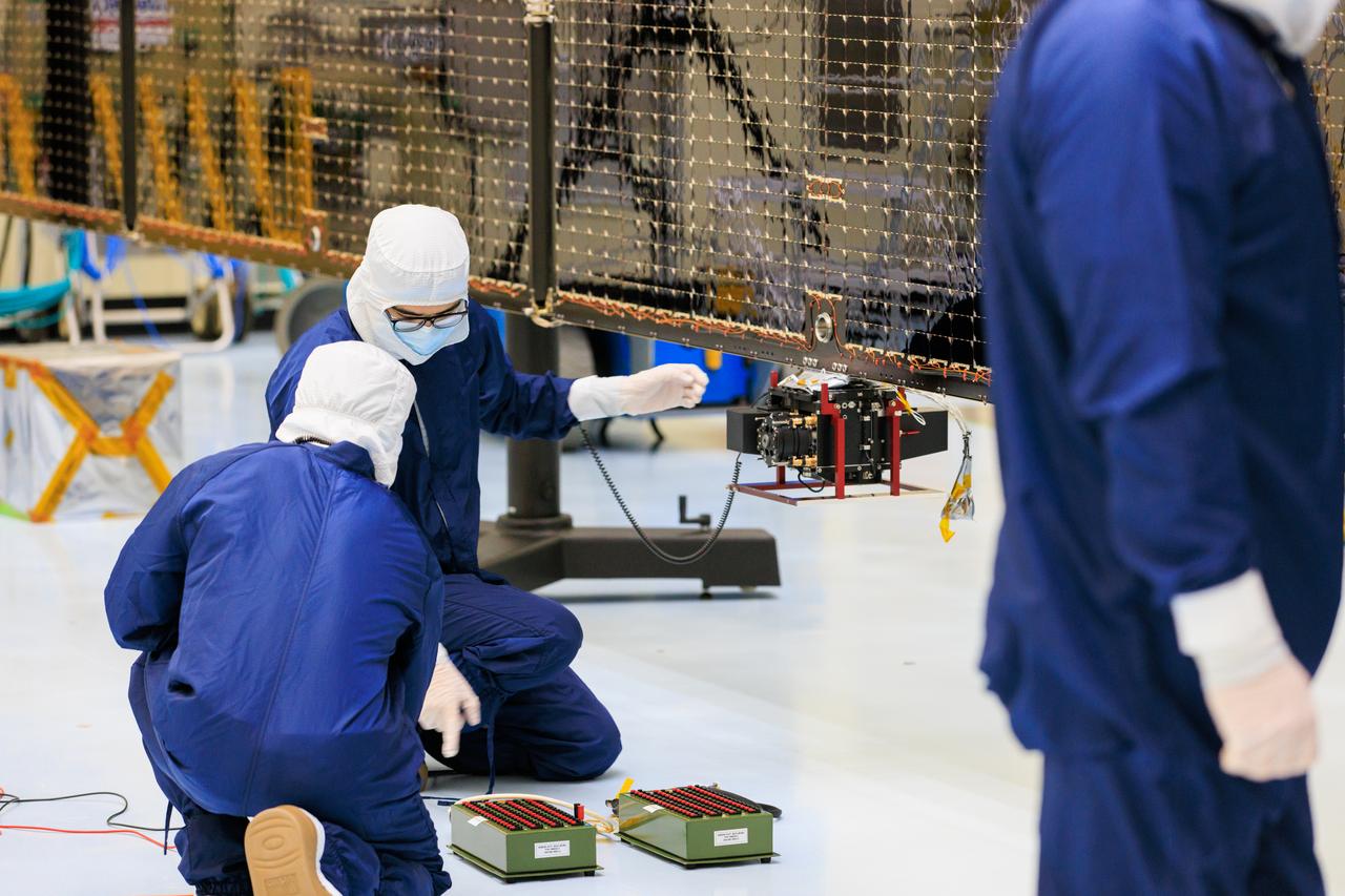
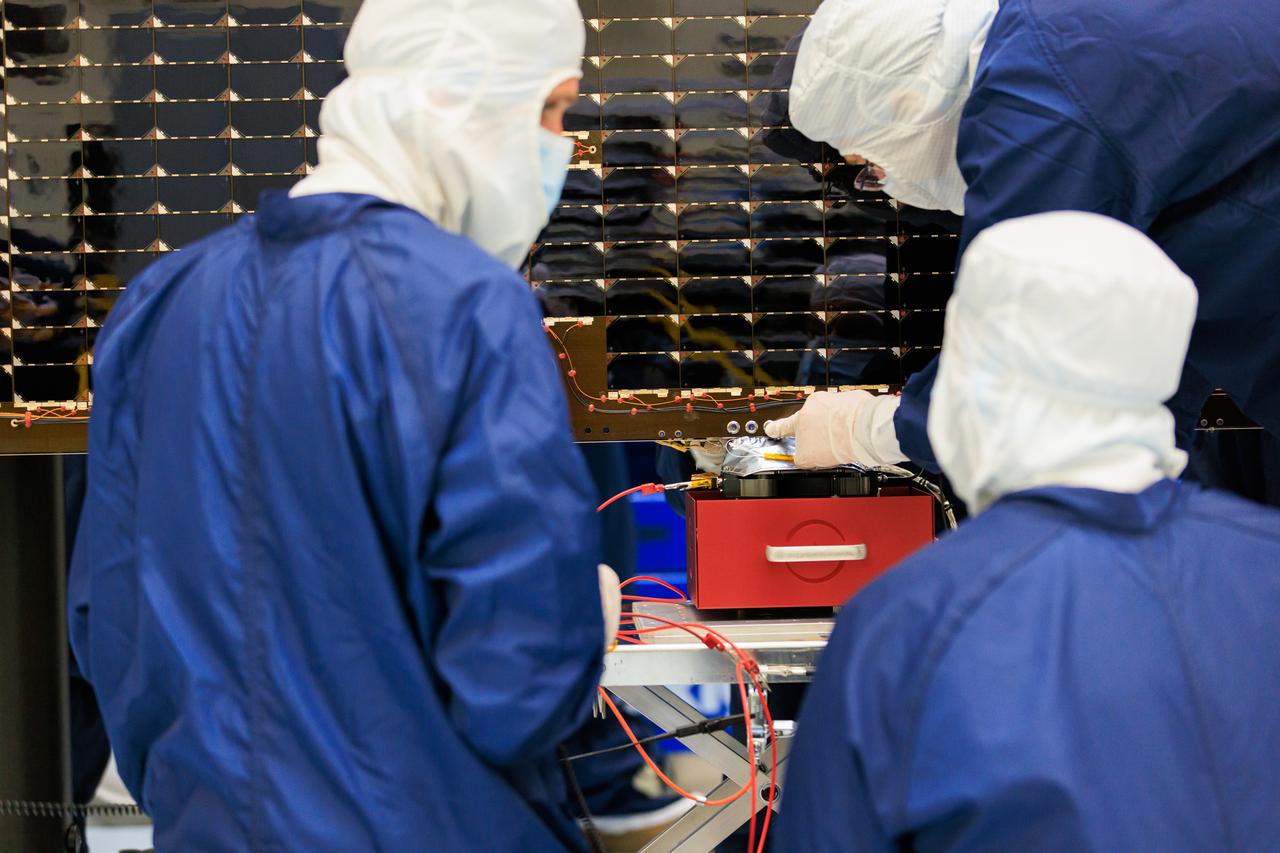
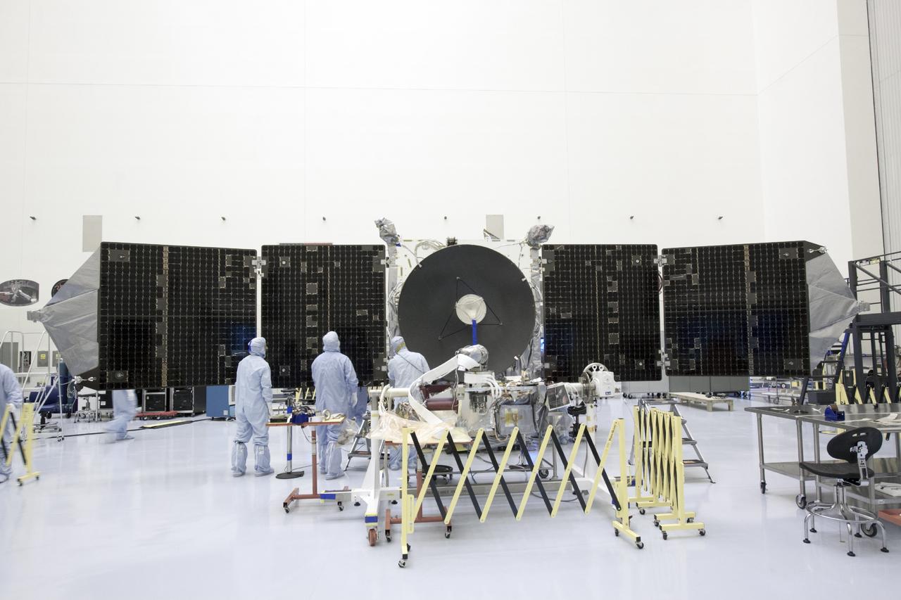
Technicians inside the Payload Hazardous Servicing Facility at NASA’s Kennedy Space Center in Florida install and test antennas on a solar array on Wednesday, March 20, 2024, for the agency’s Europa Clipper spacecraft which will study Jupiter’s icy moon Europa to determine if the planet has conditions that could support life. The REASON, (Radar for Europa Assessment and Sounding: Ocean to Near-surface) instrument will use the antennas to send both High Frequency (HF) and Very High Frequency (VHF) radio waves to penetrate up to 18 miles (30 kilometers) deep and search the ocean, measure ice thickness, and study the topography, composition, and roughness of Europa’s surface. The Europa Clipper spacecraft will ship to Florida later this year from NASA’s Jet Propulsion Lab in Southern California in preparation for launch aboard a SpaceX Falcon Heavy rocket from Kennedy’s Launch Complex 39A targeting October.
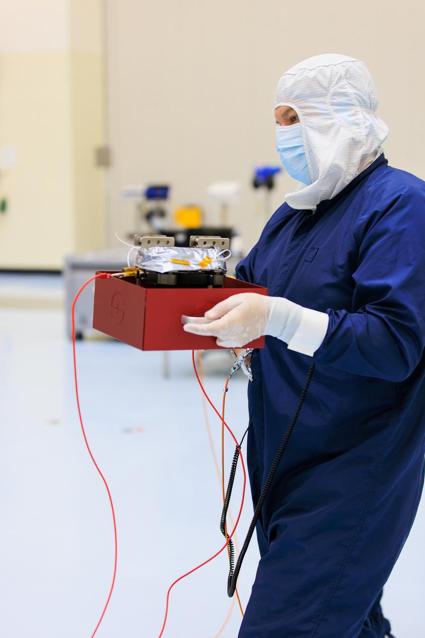
On Wednesday, March 20, 2024, a technician inside the Payload Hazardous Servicing Facility at NASA’s Kennedy Space Center in Florida carries an antenna that will attach to a solar array for the agency’s Europa Clipper spacecraft, which will study Jupiter’s icy moon Europa to determine if the planet has conditions that could support life. The REASON, (Radar for Europa Assessment and Sounding: Ocean to Near-surface) instrument will use the antennas to send both High Frequency (HF) and Very High Frequency (VHF) radio waves to penetrate up to 18 miles (30 kilometers) deep and search the ocean, measure ice thickness, and study the topography, composition, and roughness of Europa’s surface. The Europa Clipper spacecraft will ship to Florida later this year from NASA’s Jet Propulsion Lab in Southern California in preparation for launch aboard a SpaceX Falcon Heavy rocket from Kennedy’s Launch Complex 39A targeting October 2024.
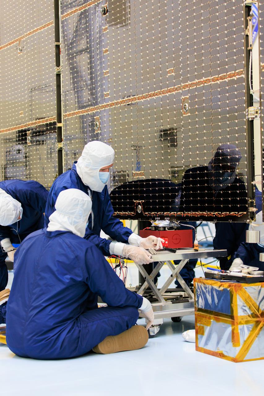
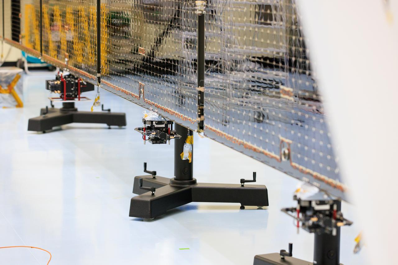
Technicians inside the Payload Hazardous Servicing Facility at NASA’s Kennedy Space Center in Florida install and test one of several antennas on a solar array Wednesday, March 20, 2024, for the agency’s Europa Clipper spacecraft which will study Jupiter’s icy moon, Europa, to determine if the planet can support life. REASON, (Radar for Europa Assessment and Sounding: Ocean to Near-surface) instrument will use the antennas to send both very high frequency radio waves and high frequency to penetrate up to 18 miles (30 kilometers) deep to search the ocean, measure ice thickness, and study the topography, composition, and roughness of Europa’s surface. The Europa Clipper spacecraft will ship to Florida later this year from NASA’s Jet Propulsion Lab in Southern California in preparation for launch aboard a SpaceX Falcon Heavy rocket from Kennedy’s Launch Complex 39A targeting October 2024.
Technicians inside the Payload Hazardous Servicing Facility at NASA’s Kennedy Space Center in Florida install and test one of several antennas on a solar array Wednesday, March 20, 2024, for the agency’s Europa Clipper spacecraft which will study Jupiter’s icy moon Europa to determine if the planet has conditions that could support life. REASON, (Radar for Europa Assessment and Sounding: Ocean to Near-surface) instrument will use the antennas to send both High Frequency (HF) and Very High Frequency (VHF) radio waves to penetrate up to 18 miles (30 kilometers) deep and search the ocean, measure ice thickness, and study the topography, composition, and roughness of Europa’s surface. The Europa Clipper spacecraft will ship to Florida later this year from NASA’s Jet Propulsion Lab in Southern California in preparation for launch aboard a SpaceX Falcon Heavy rocket from Kennedy’s Launch Complex 39A targeting October 2024.
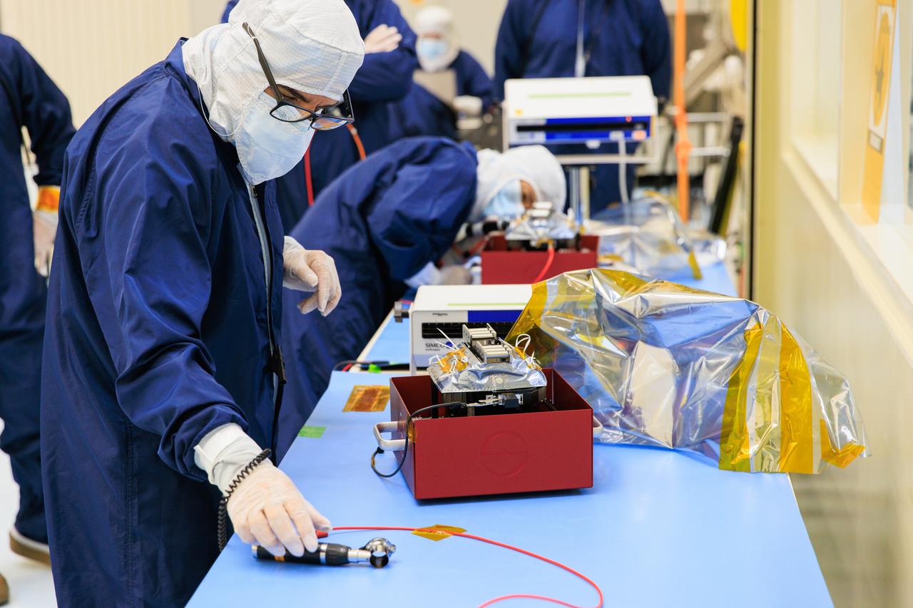
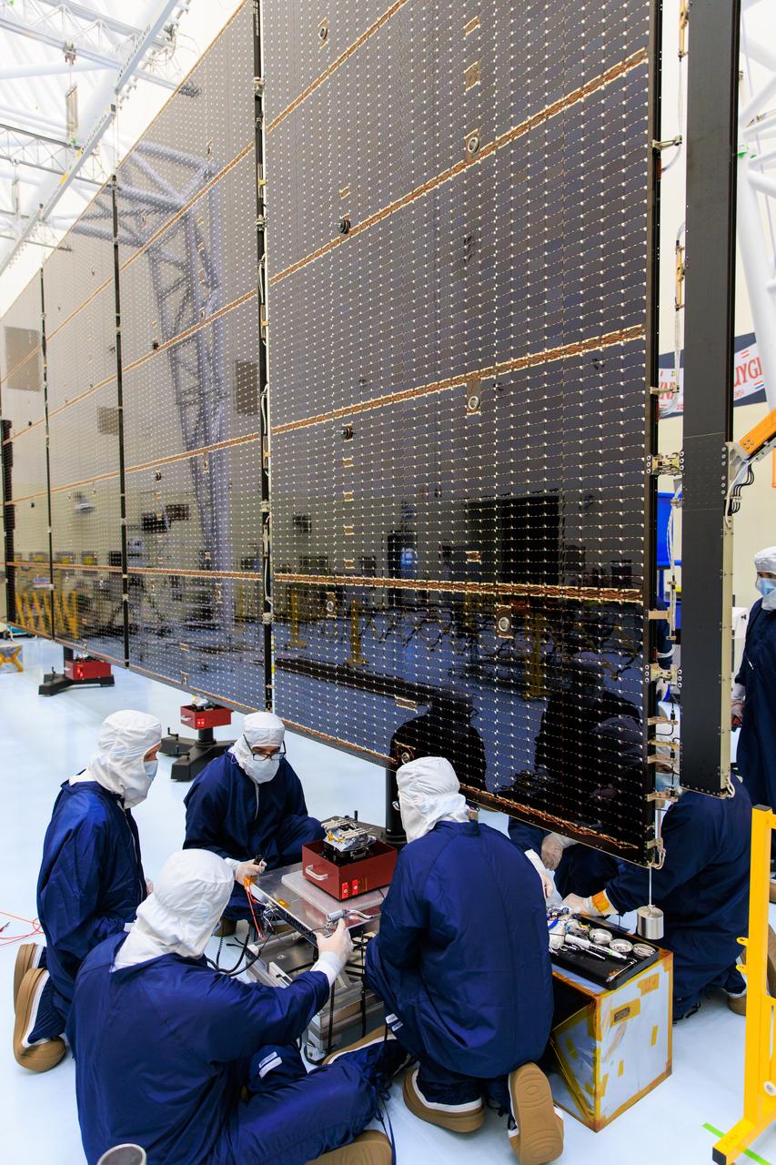
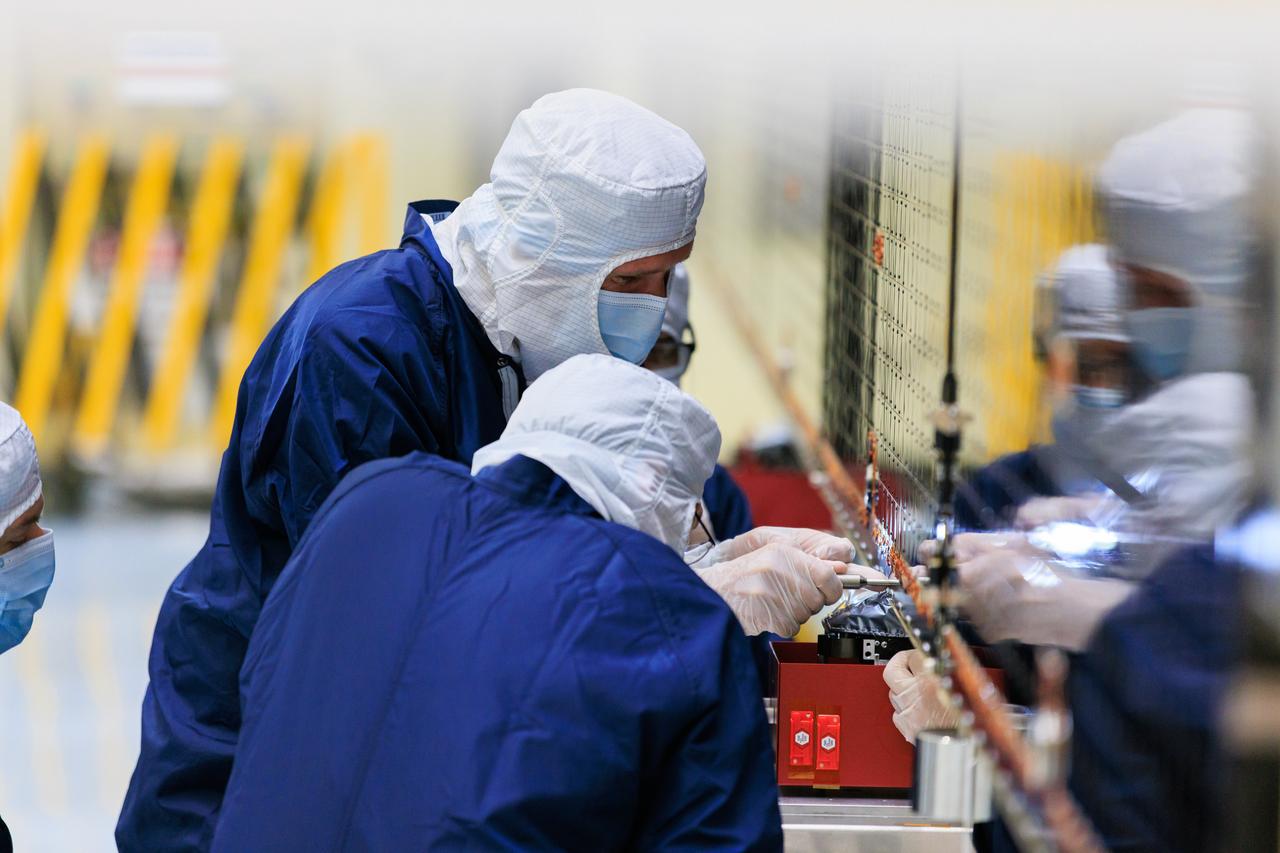
Technicians inside the Payload Hazardous Servicing Facility at NASA’s Kennedy Space Center in Florida test antennas on Wednesday, March 20, 2024, shortly before installing them on a solar array for the agency’s Europa Clipper spacecraft, which will study Jupiter’s icy moon Europa to determine if the planet has conditions that could support life. The REASON, (Radar for Europa Assessment and Sounding: Ocean to Near-surface) instrument will use the antennas to send both High Frequency (HF) and Very High Frequency (VHF) to penetrate up to 18 miles (30 kilometers) deep and search the ocean, measure ice thickness, and study the topography, composition, and roughness of Europa’s surface. The Europa Clipper spacecraft will ship to Florida later this year from NASA’s Jet Propulsion Lab in Southern California in preparation for launch aboard a SpaceX Falcon Heavy rocket from Kennedy’s Launch Complex 39A targeting October 2024.
Technicians inside the Payload Hazardous Servicing Facility at NASA’s Kennedy Space Center in Florida install and test one of several antennas on a solar array Wednesday, March 20, 2024, for the agency’s Europa Clipper spacecraft which will study Jupiter’s icy moon Europa to determine if the planet has conditions that could support life. REASON, (Radar for Europa Assessment and Sounding: Ocean to Near-surface) instrument will use the antennas to send both High Frequency (HF) and Very High Frequency (VHF) radio waves to penetrate up to 18 miles (30 kilometers) deep and search the ocean, measure ice thickness, and study the topography, composition, and roughness of Europa’s surface. The Europa Clipper spacecraft will ship to Florida later this year from NASA’s Jet Propulsion Lab in Southern California in preparation for launch aboard a SpaceX Falcon Heavy rocket from Kennedy’s Launch Complex 39A targeting October 2024.
Technicians inside the Payload Hazardous Servicing Facility at NASA’s Kennedy Space Center in Florida install and test one of several antennas on a solar array Wednesday, March 20, 2024, for the agency’s Europa Clipper spacecraft which will study Jupiter’s icy moon Europa to determine if the planet has conditions that could support life. REASON, (Radar for Europa Assessment and Sounding: Ocean to Near-surface) instrument will use the antennas to send both High Frequency (HF) and Very High Frequency (VHF) radio waves to penetrate up to 18 miles (30 kilometers) deep and search the ocean, measure ice thickness, and study the topography, composition, and roughness of Europa’s surface. The Europa Clipper spacecraft will ship to Florida later this year from NASA’s Jet Propulsion Lab in Southern California in preparation for launch aboard a SpaceX Falcon Heavy rocket from Kennedy’s Launch Complex 39A targeting October 2024.
Technicians inside the Payload Hazardous Servicing Facility at NASA’s Kennedy Space Center in Florida install and test antennas on a solar array on Wednesday, March 20, 2024, for the agency’s Europa Clipper spacecraft which will study Jupiter’s icy moon Europa to determine if the planet has conditions that could support life. The REASON, (Radar for Europa Assessment and Sounding: Ocean to Near-surface) instrument will use the antennas to send both both High Frequency (HF) and Very High Frequency (VHF) radio waves to penetrate up to 18 miles (30 kilometers) deep and search the ocean, measure ice thickness, and study the topography, composition, and roughness of Europa’s surface. The Europa Clipper spacecraft will ship to Florida later this year from NASA’s Jet Propulsion Lab in Southern California in preparation for launch aboard a SpaceX Falcon Heavy rocket from Kennedy’s Launch Complex 39A targeting October.
Technicians inside the Payload Hazardous Servicing Facility at NASA’s Kennedy Space Center in Florida install and test antennas on a solar array on Wednesday, March 20, 2024, for the agency’s Europa Clipper spacecraft which will study Jupiter’s icy moon Europa to determine if the planet has conditions that could support life. The REASON, (Radar for Europa Assessment and Sounding: Ocean to Near-surface) instrument will use the antennas to send both High Frequency (HF) and Very High Frequency (VHF) radio waves to penetrate up to 18 miles (30 kilometers) deep and search the ocean, measure ice thickness, and study the topography, composition, and roughness of Europa’s surface. The Europa Clipper spacecraft will ship to Florida later this year from NASA’s Jet Propulsion Lab in Southern California in preparation for launch aboard a SpaceX Falcon Heavy rocket from Kennedy’s Launch Complex 39A targeting October.
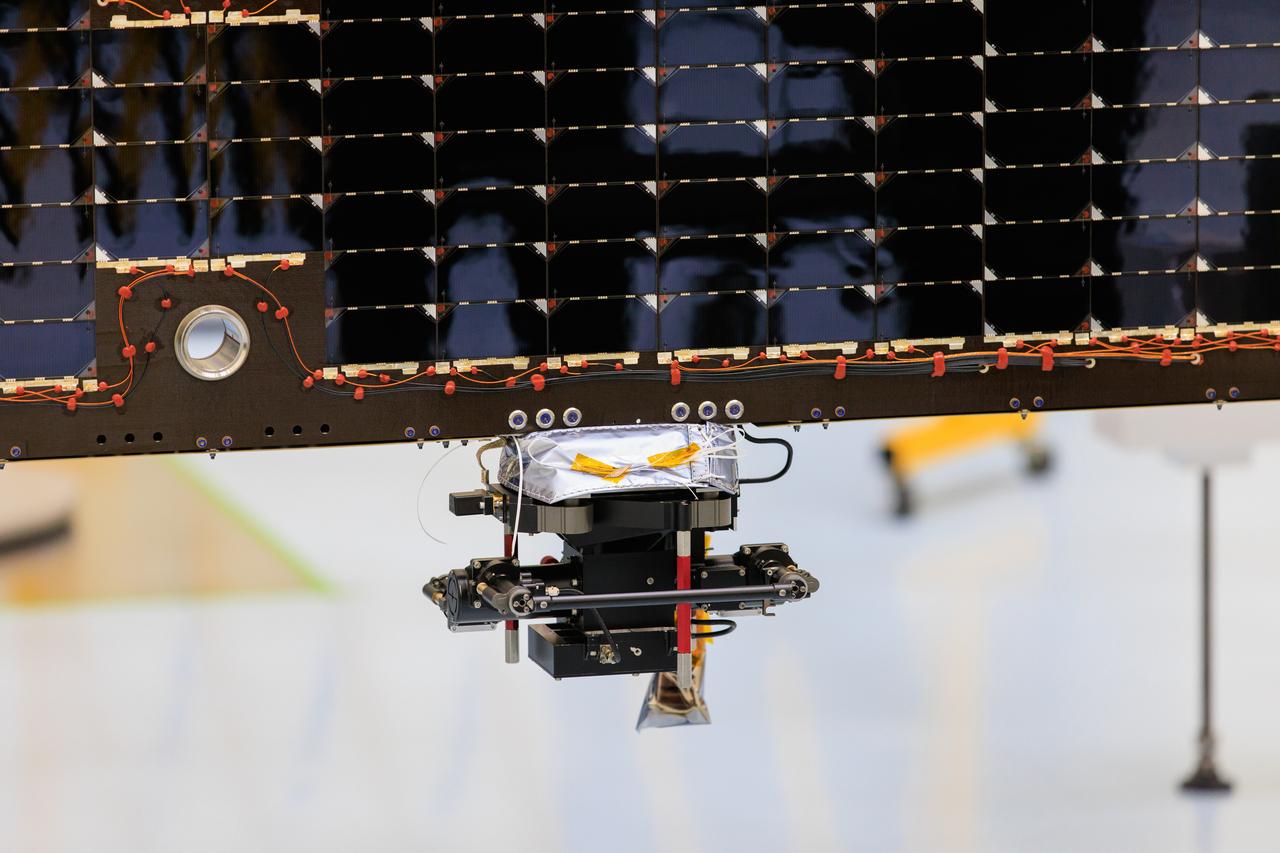
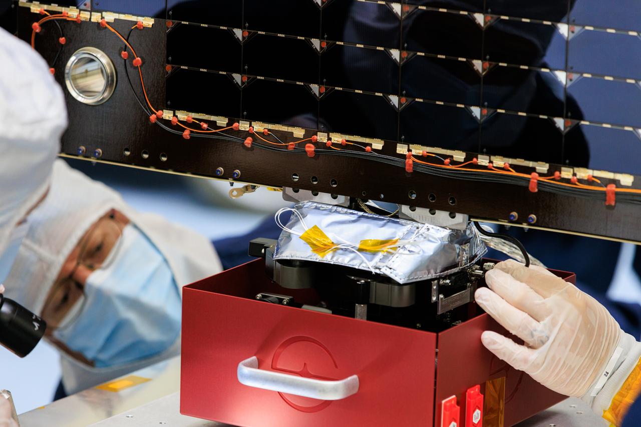
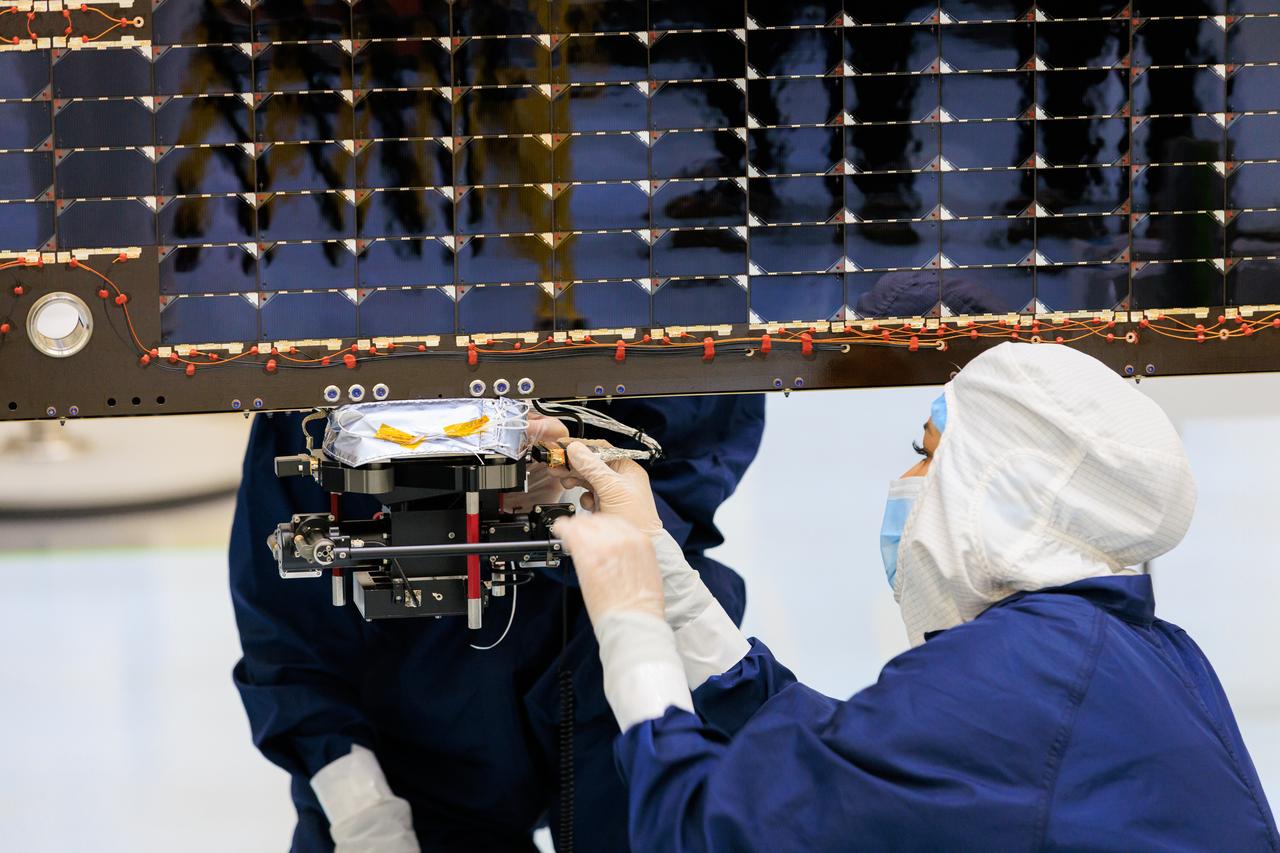
An antenna for the REASON, (Radar for Europa Assessment and Sounding: Ocean to Near-surface) instrument attaches to a solar array for NASA’s Europa Clipper spacecraft inside the Payload Hazardous Servicing Facility at the agency’s Kennedy Space Center in Florida on Wednesday, March 20, 2024. The Europa Clipper spacecraft will study Jupiter’s icy moon Europa, and the REASON instrument will use the antennas to send both both High Frequency (HF) and Very High Frequency (VHF) radio waves to penetrate up to 18 miles (30 kilometers) deep and search the ocean, measure ice thickness, and study the topography, composition, and roughness of Europa’s surface. The Europa Clipper spacecraft will ship to Florida later this year from NASA’s Jet Propulsion Lab in Southern California in preparation for launch aboard a SpaceX Falcon Heavy rocket from Kennedy’s Launch Complex 39A, targeting October.
Technicians inside the Payload Hazardous Servicing Facility at NASA’s Kennedy Space Center in Florida install and test one of several antennas on a solar array Wednesday, March 20, 2024, for the agency’s Europa Clipper spacecraft which will study Jupiter’s icy moon Europa to determine if the planet has conditions that could support life. REASON, (Radar for Europa Assessment and Sounding: Ocean to Near-surface) instrument will use the antennas to send both High Frequency (HF) and Very High Frequency (VHF) radio waves to penetrate up to 18 miles (30 kilometers) deep and search the ocean, measure ice thickness, and study the topography, composition, and roughness of Europa’s surface. The Europa Clipper spacecraft will ship to Florida later this year from NASA’s Jet Propulsion Lab in Southern California in preparation for launch aboard a SpaceX Falcon Heavy rocket from Kennedy’s Launch Complex 39A targeting October 2024.
Technicians inside the Payload Hazardous Servicing Facility at NASA’s Kennedy Space Center in Florida install and test antennas on a solar array on Wednesday, March 20, 2024, for the agency’s Europa Clipper spacecraft which will study Jupiter’s icy moon Europa to determine if the planet has conditions that could support life. The REASON, (Radar for Europa Assessment and Sounding: Ocean to Near-surface) instrument will use the antennas to send both High Frequency (HF) and Very High Frequency (VHF) radio waves to penetrate up to 18 miles (30 kilometers) deep and search the ocean, measure ice thickness, and study the topography, composition, and roughness of Europa’s surface. The Europa Clipper spacecraft will ship to Florida later this year from NASA’s Jet Propulsion Lab in Southern California in preparation for launch aboard a SpaceX Falcon Heavy rocket from Kennedy’s Launch Complex 39A targeting October.
Technicians inside the Payload Hazardous Servicing Facility at NASA’s Kennedy Space Center in Florida install and test one of several antennas on a solar array Wednesday, March 20, 2024, for the agency’s Europa Clipper spacecraft which will study Jupiter’s icy moon Europa to determine if the planet has conditions that could support life. REASON, (Radar for Europa Assessment and Sounding: Ocean to Near-surface) instrument will use the antennas to send both High Frequency (HF) and Very High Frequency (VHF) radio waves to penetrate up to 18 miles (30 kilometers) deep and search the ocean, measure ice thickness, and study the topography, composition, and roughness of Europa’s surface. The Europa Clipper spacecraft will ship to Florida later this year from NASA’s Jet Propulsion Lab in Southern California in preparation for launch aboard a SpaceX Falcon Heavy rocket from Kennedy’s Launch Complex 39A targeting October 2024.
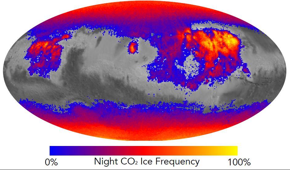
This map shows the frequency of carbon dioxide frost's presence at sunrise on Mars, as a percentage of days year-round. Carbon dioxide ice more often covers the ground at night in some mid-latitude regions than in polar regions, where it is generally absent for much of summer and fall. Color coding is based on data from the Mars Climate Sounder instrument on NASA's Mars Reconnaissance Orbiter. A color-key bar below the map shows how colors correspond to frequencies. Yellow indicates high frequencies, identifying areas where carbon dioxide ice is present on the ground at night during most of the year. Blue identifies areas where it is rarely present; red is intermediate. Areas without color coding are regions where carbon dioxide frost is not detected at any time of year. The areas with highest frequency of overnight carbon dioxide frost correspond to regions with surfaces of loose dust, which do not retain heat well, compared to rockier areas. Those areas also have some of the highest mid-afternoon temperatures on the planet. The dust surface heats up and cools off rapidly. http://photojournal.jpl.nasa.gov/catalog/PIA20758
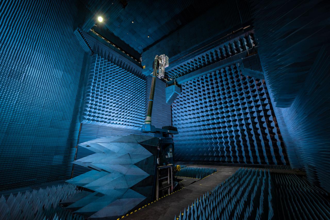
jsc2021e022487 (June 11, 2021) --- NASA’s Exploration Extravehicular Mobility Unit (xEMU) spacesuit undergoes antenna testing in NASA Johnson Space Center’s anechoic chamber to inspect multi-layer insulation keep-out zones for the Wi-Fi and ultra-high-frequency antennas that are part of the spacesuit’s communication system. The xEMU test article is named xGUS, the successor to the Extravehicular Mobility Unit test article (also named GUS), which was named after NASA astronaut Gus Grissom and his iconic silver spacesuit. This image was taken from where the "horn," or source antenna, is located that sends out radio frequency signals to the spacesuit. The anechoic chamber walls are covered with a material that absorbs electromagnetic energy allowing the anechoic chamber to simulate a space environment. The antenna test facility is utilized to test antenna radiation distribution pattern performance for spaceflight applications in electromagnetic environments.

jsc2021e022515 (June 11, 2021) --- NASA’s Exploration Extravehicular Mobility Unit (xEMU) spacesuit undergoes antenna testing in NASA Johnson Space Center’s anechoic chamber to inspect multi-layer insulation keep-out zones for the Wi-Fi and ultra-high-frequency antennas that are part of the spacesuit’s communication system. The xEMU test article is named xGUS, the successor to the Extravehicular Mobility Unit test article (also named GUS), which was named after NASA astronaut Gus Grissom and his iconic silver spacesuit. This image was taken from where the "horn," or source antenna, is located that sends out radio frequency signals to the spacesuit. The anechoic chamber walls are covered with a material that absorbs electromagnetic energy allowing the anechoic chamber to simulate a space environment. The antenna test facility is utilized to test antenna radiation distribution pattern performance for spaceflight applications in electromagnetic environments. Pictured in the photo is antenna test engineer Will Bond.
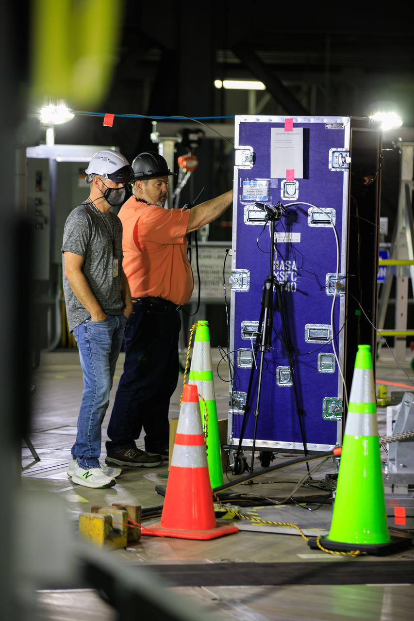
Artemis teams members perform the integrated modal test of the Space Launch System and mobile launcher in High Bay 3 of the Vehicle Assembly Building at NASA’s Kennedy Space Center in Florida on Sept. 24, 2021. The tests will help determine the natural frequencies of the recently stacked rocket before launch of the Artemis I mission. The data also will be used to help steer the rocket during flight. To identify the rocket’s natural frequencies, the team placed about 300 sensors on it and the mobile launcher to detect, record, and transmit the information, along with hydraulic shakers attached to seven locations on the rocket. Artemis I will be the first integrated test of the SLS and Orion spacecraft. In later missions, NASA will land the first woman and the first person of color on the surface of the Moon, paving the way for a long-term lunar presence and serving as a steppingstone on the way to Mars.
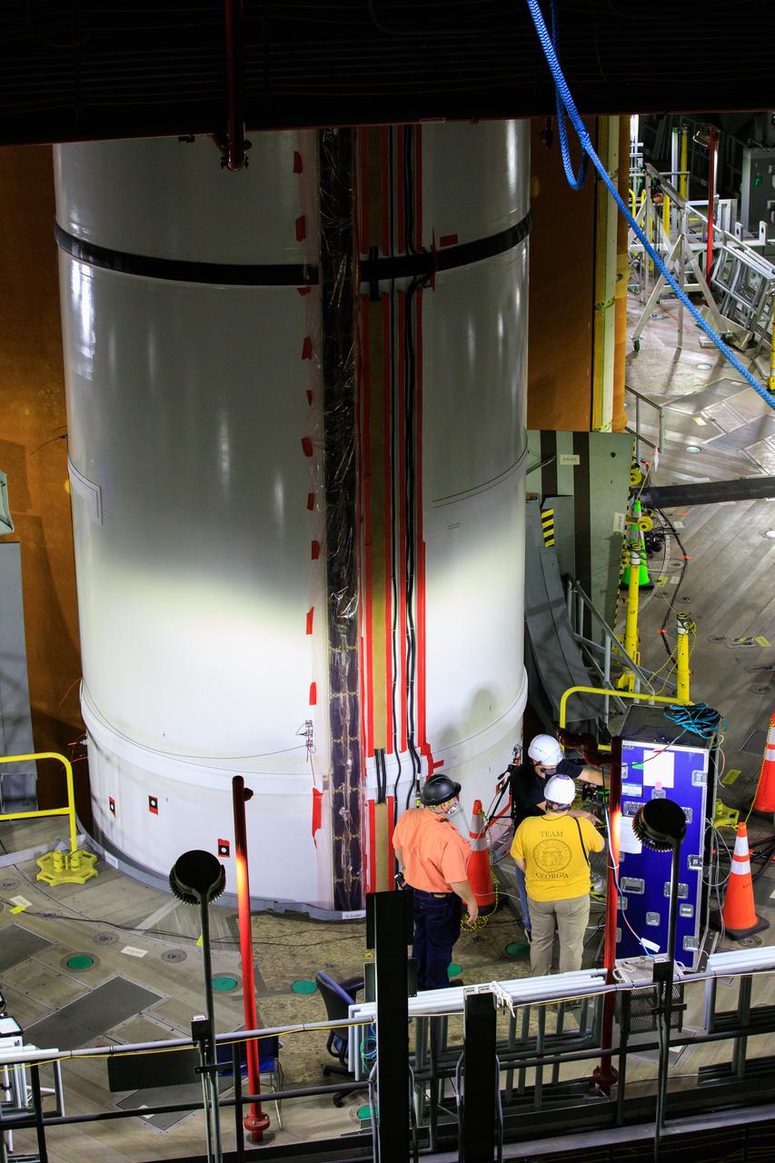
Artemis teams members perform the integrated modal test of the Space Launch System and mobile launcher in High Bay 3 of the Vehicle Assembly Building at NASA’s Kennedy Space Center in Florida on Sept. 24, 2021. The tests will help determine the natural frequencies of the recently stacked rocket before launch of the Artemis I mission. The data also will be used to help steer the rocket during flight. To identify the rocket’s natural frequencies, the team placed about 300 sensors on it and the mobile launcher to detect, record, and transmit the information, along with hydraulic shakers attached to seven locations on the rocket. Artemis I will be the first integrated test of the SLS and Orion spacecraft. In later missions, NASA will land the first woman and the first person of color on the surface of the Moon, paving the way for a long-term lunar presence and serving as a steppingstone on the way to Mars.

jsc2021e022488 (June 11, 2021) --- NASA’s Exploration Extravehicular Mobility Unit (xEMU) spacesuit undergoes antenna testing in NASA Johnson Space Center’s anechoic chamber to inspect multi-layer insulation keep-out zones for the Wi-Fi and ultra-high-frequency antennas that are part of the spacesuit’s communication system. The xEMU test article is named xGUS, the successor to the Extravehicular Mobility Unit test article (also named GUS), which was named after NASA astronaut Gus Grissom and his iconic silver spacesuit. This image was taken from where the "horn," or source antenna, is located that sends out radio frequency signals to the spacesuit. The anechoic chamber walls are covered with a material that absorbs electromagnetic energy allowing the anechoic chamber to simulate a space environment. The antenna test facility is utilized to test antenna radiation distribution pattern performance for spaceflight applications in electromagnetic environments. Pictured in the photo is antenna test engineer Will Bond.
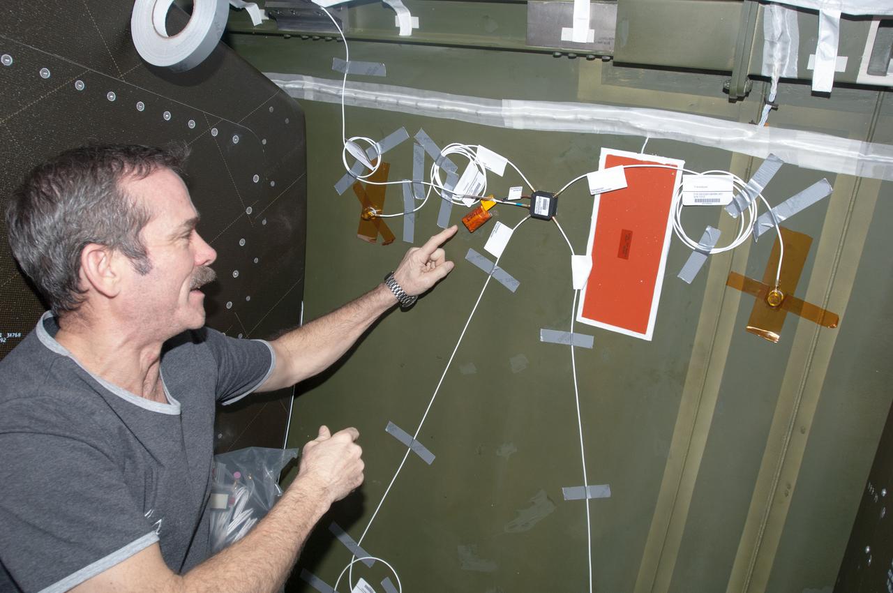
ISS034-E-038211 (1 Feb. 2013) --- Canadian Space Agency astronaut Chris Hadfield, Expedition 34 flight engineer, installs Ultra-Sonic Background Noise Tests (UBNT) sensors behind a rack in the Destiny laboratory, using the International Space Station (ISS) as Testbed for Analog Research (ISTAR) procedures. These sensors detect high frequency noise levels generated by ISS hardware and equipment operating within Destiny.

Dan Sokolowski worked as an engineering coop student at the National Aeronautics and Space Administration (NASA) Lewis Research Center from 1962 to 1966 while earning his Mechanical Engineering degree from Purdue. At the time of this photograph Sokolowski had just been hired as a permanent NASA employee in the Chemical Rocket Evaluation Branch of the Chemical Rocket Division. He had also just won a regional American Institute of Aeronautics and Astronautics competition for his paper on high and low-frequency combustion instability. The resolution of the low-frequency combustion instability, or chugging, in liquid hydrogen rocket systems was one of Lewis’ more significant feats of the early 1960s. In most rocket engine combustion chambers, the pressure, temperature, and flows are in constant flux. The engine is considered to be operating normally if the fluctuations remain random and within certain limits. Lewis researchers used high-speed photography to study and define Pratt and Whitney’s RL-10’s combustion instability by throttling the engine under the simulated flight conditions. They found that the injection of a small stream of helium gas into the liquid-oxygen tank immediately stabilized the system. Sokolowski’s later work focused on combustion in airbreathing engines. In 1983 was named Manager of a multidisciplinary program aimed at improving durability of combustor and turbine components. After 39 years Sokolowski retired from NASA in September 2002.
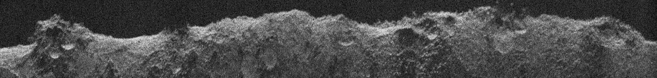
NASA's Europa Clipper, en route to the Jupiter system to investigate the icy moon Europa, conducted a critical test of its radar instrument during a flyby of Mars on March 1, 2025. During the testing, the instrument received echoes of its very-high-frequency radar signals that engineers processed to develop this image, called a radargram. The image was made using radar signals that bounced off Mars. What looks like a skyline is the outline of the topography. Features seen in the radargram include contributions from the topographic features both along and near the ground track (the path below the spacecraft as it passed overhead), such as impact craters, hills, and steep slopes. The 560-mile-long (900-kilometer-long) section of terrain profiled in this radargram is near Mars' equator. The Europa Clipper radar instrument, REASON (Radar for Europa Assessment and Sounding: Ocean to Near-surface), is designed to see into the icy crust of Europa. Though the rocky Martian surface does not allow much penetration by the radar signals, the clarity of the radargram image indicates REASON was performing as expected during the Mars flyby, boding well for future observations at Europa. As Europa Clipper zipped by the Red Planet – starting at 3,100 miles (5,000 kilometers) down to 550 miles (884 kilometers) above the surface – REASON sent and received radio waves for about 40 minutes. In comparison, at Europa the instrument will operate as close as 16 miles (25 kilometers) from the moon's surface. Europa Clipper launched from NASA's Kennedy Space Center in Florida on Oct. 14, 2024, and will arrive at the Jupiter system in 2030 to conduct about 50 flybys of Europa. The mission's main science goal is to determine whether there are places below Europa's surface that could support life. The mission's three main science objectives are to determine the thickness of the moon's icy shell and its surface interactions with the ocean below, to investigate its composition, and to characterize its geology. The mission's detailed exploration of Europa will help scientists better understand the astrobiological potential for habitable worlds beyond our planet. https://photojournal.jpl.nasa.gov/catalog/PIA26568
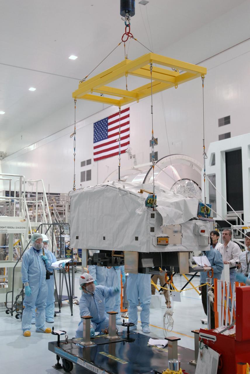
CAPE CANAVERAL, Fla. -- In the Space Station Processing Facility at NASA's Kennedy Space Center in Florida, the ICS Exposed Facility, or ICS-EF, is lifted from its stand. It will be installed on the Japanese Experiment Module's Experiment Logistics Module-Exposed Section, or ELM-ES. The ICS-EF is composed of several components, including an antenna, pointing mechanism, frequency converters, high-power amplifier and various sensors including the Earth sensor, Sun sensor and inertial reference unit. The ICS-EF is part of space shuttle Endeavour's payload on the STS-127 mission, targeted for launch on May 15. Photo credit: NASA/Jim Grossmann

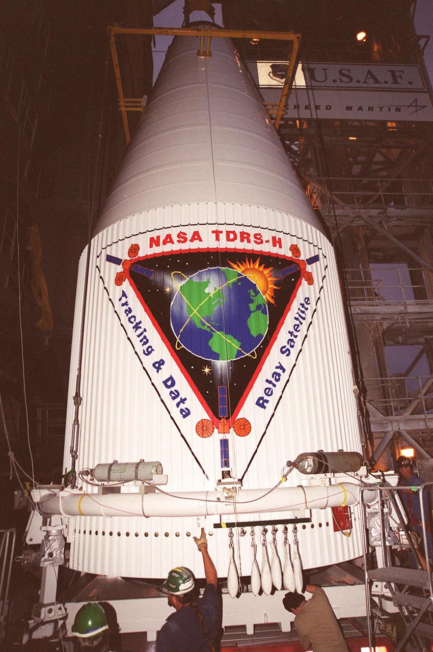
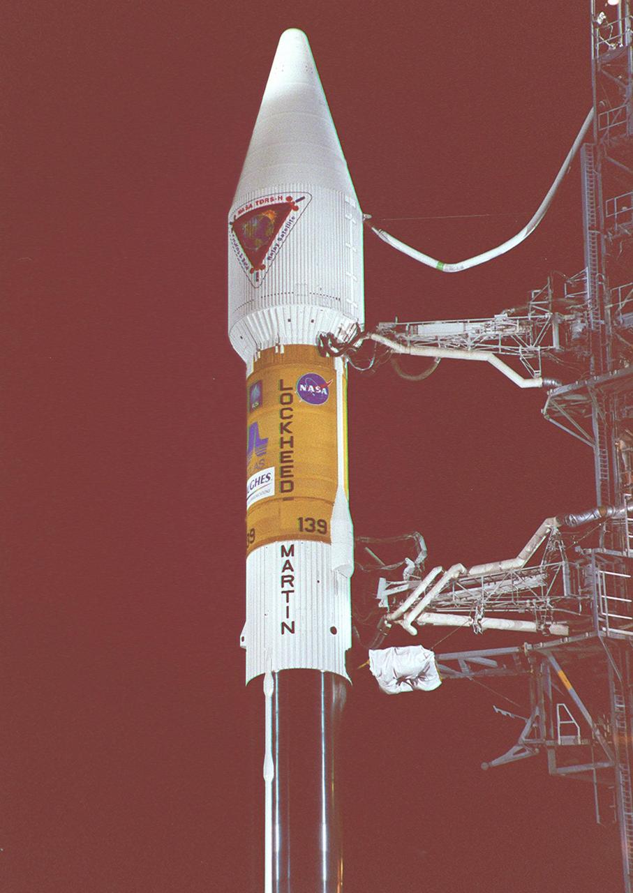
KENNEDY SPACE CENTER, FLA. -- In a view taken near the top of the launch tower at Launch Pad 36A, Cape Canaveral Air Force Station, the nose fairing with the Tracking and Data Relay Satellite (TDRS-H) inside is hoisted up the tower by the overhead crane (left). The fairing will be mated with the Atlas IIA/Centaur rocket, which is already stacked, for launch on June 29. The satellite will augment the TDRS system's existing S- and Ku-band frequencies by adding Ka-band capability. TDRS will serve as the sole means of continuous, high-data-rate communications with the Space Shuttle, with the International Space Station upon its completion, and with dozens of unmanned scientific satellites in low-earth orbit.
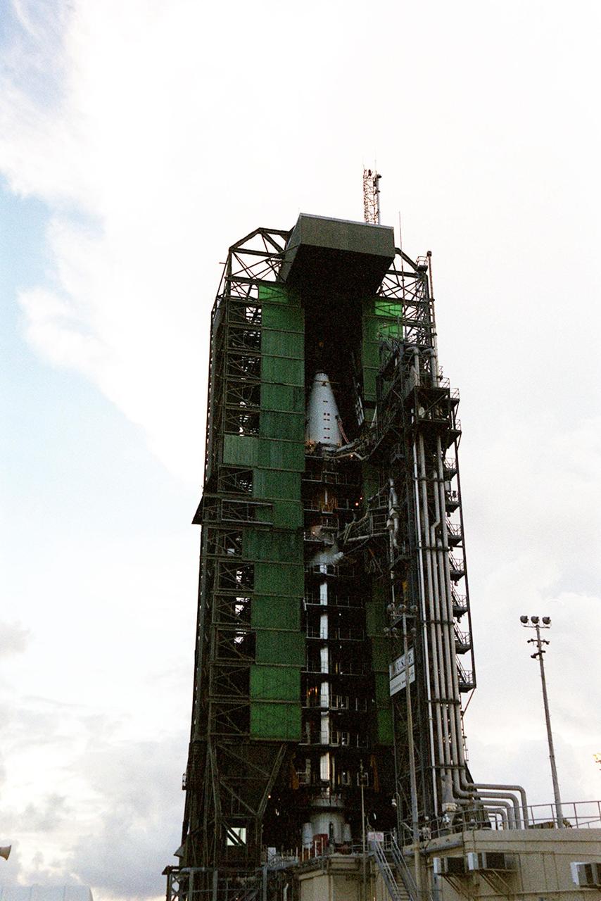
The nose fairing covering the Tracking and Data Relay Satellite (TDRS-H) is close to the top of the launch tower at Launch Pad 36A, Cape Canaveral Air Force Station. It is being lifted to mate with the Atlas IIA/Centaur rocket, which is already stacked, for launch on June 29. The satellite will augment the TDRS system’s existing Sand Ku-band frequencies by adding Ka-band capability. TDRS will serve as the sole means of continuous, high-data-rate communication with the Space Shuttle, with the International Space Station upon its completion, and with dozens of unmanned scientific satellites in low earth orbit
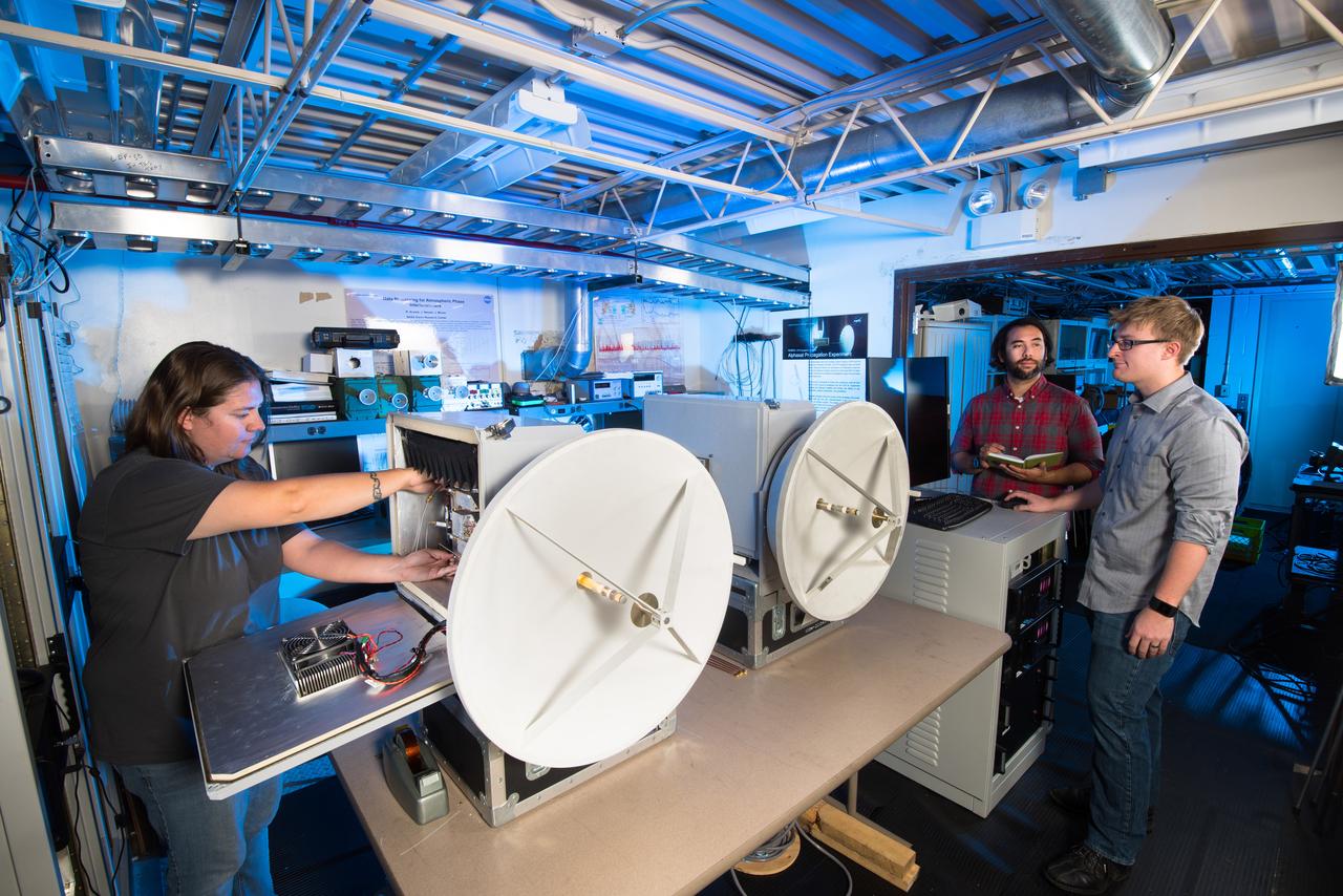
NASA Glenn researchers Jacki Houts, James Nessel and Michael Zemba perform a final inspection of the W/V-Band Terrestrial Link Experiment (WTLE) before it was transported to Albuquerque, New Mexico for testing. The experiment hardware includes a transmitter, which has been placed on the crest of the Sandia Mountains and a receiver (shown) placed at a research facility of the University of New Mexico. The wireless link spans 23km and will be used to study the effects of the atmosphere on high data-rate wireless communication links at 72 and 84 GHz. The goal of the experiment is to study these frequency bands for satellite communications.
At Launch Pad 36A, Cape Canaveral Air Force Station, workers (at left) oversee the lifting of the nose fairing covering the Tracking and Data Relay Satellite (TDRS-H). Once at the top, the fairing will be mated with the Atlas IIA/Centaur rocket, which is already stacked, for launch on June 29. The satellite will augment the TDRS system’s existing Sand Ku-band frequencies by adding Ka-band capability. TDRS will serve as the sole means of continuous, high-data-rate communication with the Space Shuttle, with the International Space Station upon its completion, and with dozens of unmanned scientific satellites in low earth orbit

At Launch Pad 36A, Cape Canaveral Air Force Station, workers (at left) oversee the lifting of the nose fairing covering the Tracking and Data Relay Satellite (TDRS-H). Once at the top, the fairing will be mated with the Atlas IIA/Centaur rocket, which is already stacked, for launch on June 29. The satellite will augment the TDRS system’s existing Sand Ku-band frequencies by adding Ka-band capability. TDRS will serve as the sole means of continuous, high-data-rate communication with the Space Shuttle, with the International Space Station upon its completion, and with dozens of unmanned scientific satellites in low earth orbit

The nose fairing covering the Tracking and Data Relay Satellite (TDRS-H) nears the top of the launch tower at Launch Pad 36A, Cape Canaveral Air Force Station. It will be mated with the Atlas IIA/Centaur rocket, which is already stacked (barely visible behind the framework on lower left), for launch on June 29. The satellite will augment the TDRS system’s existing Sand Ku-band frequencies by adding Ka-band capability. TDRS will serve as the sole means of continuous, high-data-rate communication with the Space Shuttle, with the International Space Station upon its completion, and with dozens of unmanned scientific satellites in low earth orbit
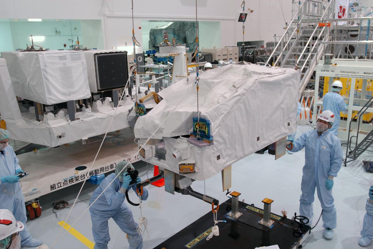
CAPE CANAVERAL, Fla. -- In the Space Station Processing Facility at NASA's Kennedy Space Center in Florida, workers examine the ICS Exposed Facility, or ICS-EF, after it is lifted from its stand. It will be installed on the Japanese Experiment Module's Experiment Logistics Module-Exposed Section, or ELM-ES. The ICS-EF is composed of several components, including an antenna, pointing mechanism, frequency converters, high-power amplifier and various sensors including the Earth sensor, Sun sensor and inertial reference unit. The ICS-EF is part of space shuttle Endeavour's payload on the STS-127 mission, targeted for launch on May 15. Photo credit: NASA/Jim Grossmann
KENNEDY SPACE CENTER, FLA. -- In a view taken near the top of the launch tower at Launch Pad 36A, Cape Canaveral Air Force Station, the nose fairing with the Tracking and Data Relay Satellite (TDRS-H) inside is hoisted up the tower by the overhead crane (left). The fairing will be mated with the Atlas IIA/Centaur rocket, which is already stacked, for launch on June 29. The satellite will augment the TDRS system's existing S- and Ku-band frequencies by adding Ka-band capability. TDRS will serve as the sole means of continuous, high-data-rate communications with the Space Shuttle, with the International Space Station upon its completion, and with dozens of unmanned scientific satellites in low-earth orbit.
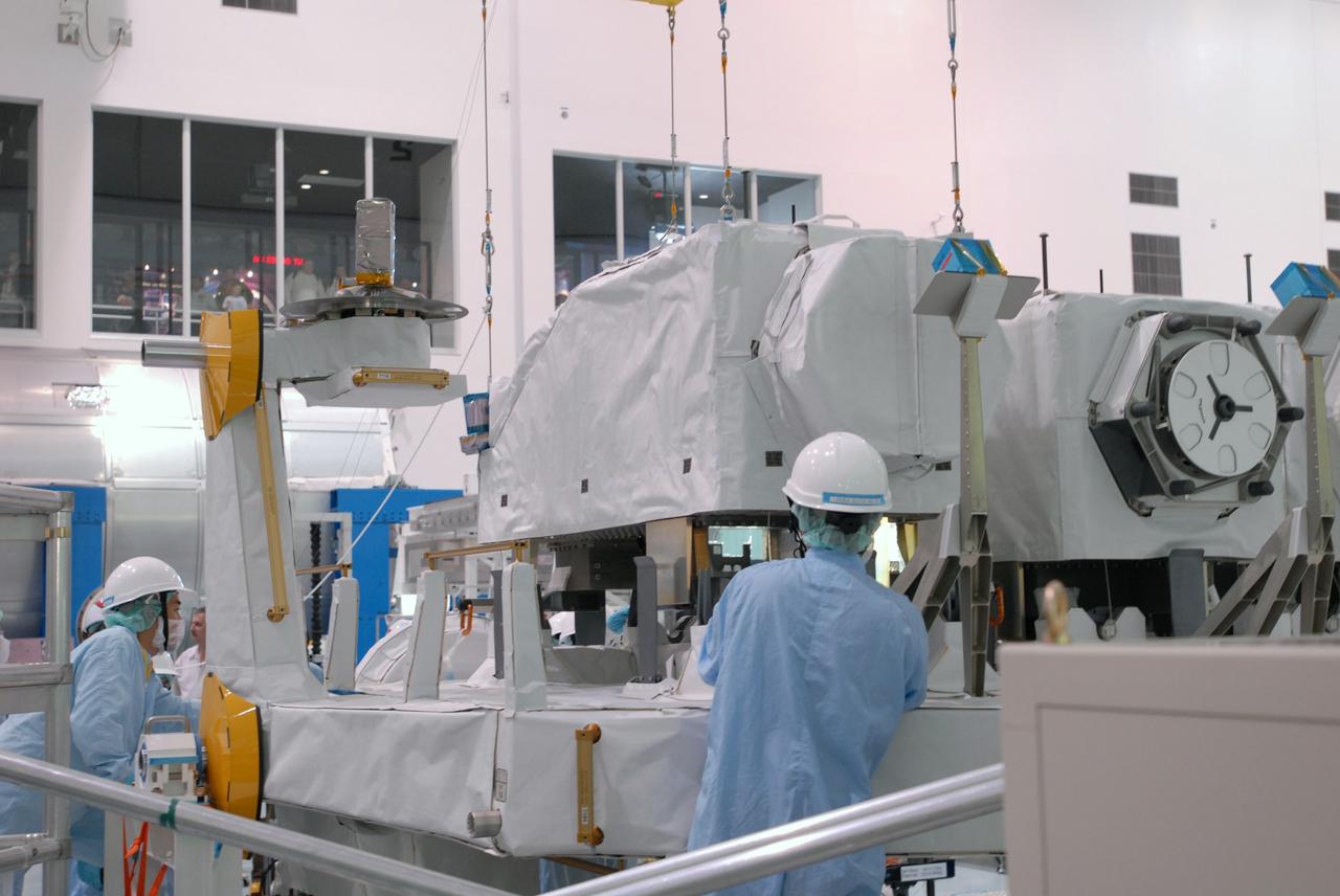
CAPE CANAVERAL, Fla. -- In the Space Station Processing Facility at NASA's Kennedy Space Center in Florida, an overhead crane lowers the ICS Exposed Facility, or ICS-EF, onto the Japanese Experiment Module's Experiment Logistics Module-Exposed Section, or ELM-ES, for installation. The ICS-EF is composed of several components, including an antenna, pointing mechanism, frequency converters, high-power amplifier and various sensors including the Earth sensor, Sun sensor and inertial reference unit. The ICS-EF is part of space shuttle Endeavour's payload on the STS-127 mission, targeted for launch on May 15. Photo credit: NASA/Jim Grossmann
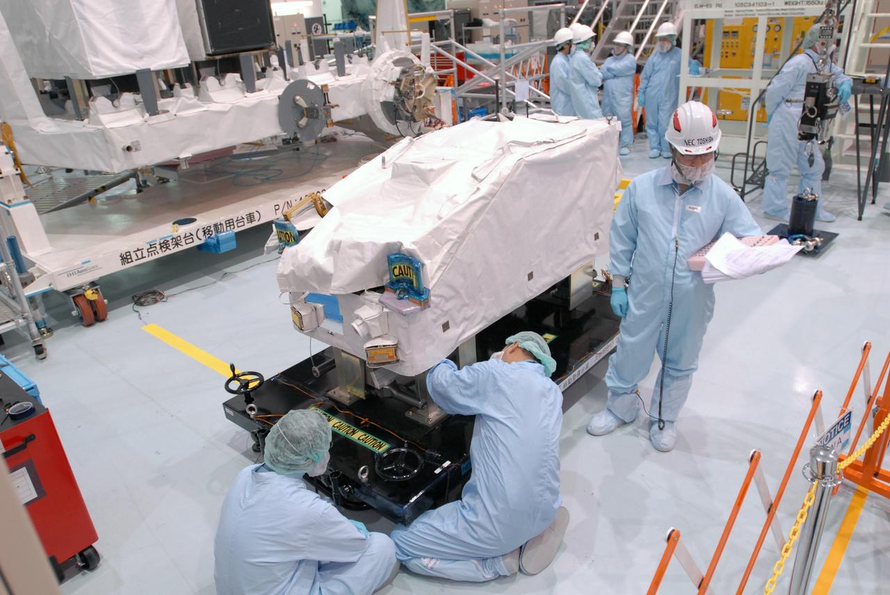
CAPE CANAVERAL, Fla. -- In the Space Station Processing Facility at NASA's Kennedy Space Center in Florida, workers prepare the ICS Exposed Facility, ICS-EF, to be lifted and installed on the Japanese Experiment Module's Experiment Logistics Module-Exposed Section, or ELM-ES. The ICS-EF is composed of several components, including an antenna, pointing mechanism, frequency converters, high-power amplifier and various sensors including the Earth sensor, Sun sensor and inertial reference unit. The ICS-EF is part of space shuttle Endeavour's payload on the STS-127 mission, targeted for launch on May 15. Photo credit: NASA/Jim Grossmann

The nose fairing covering the Tracking and Data Relay Satellite (TDRS-H) is close to the top of the launch tower at Launch Pad 36A, Cape Canaveral Air Force Station. It is being lifted to mate with the Atlas IIA/Centaur rocket, which is already stacked, for launch on June 29. The satellite will augment the TDRS system’s existing Sand Ku-band frequencies by adding Ka-band capability. TDRS will serve as the sole means of continuous, high-data-rate communication with the Space Shuttle, with the International Space Station upon its completion, and with dozens of unmanned scientific satellites in low earth orbit

An overhead crane is positioned on the nose fairing covering the Tracking and Data Relay Satellite (TDRS-H) in order to lift it up the tower at Launch Pad 36A, Cape Canaveral Air Force Station. It will be mated with the Atlas IIA/Centaur rocket, which is already stacked, for launch on June 29. The satellite will augment the TDRS system’s existing Sand Ku-band frequencies by adding Ka-band capability. TDRS will serve as the sole means of continuous, high-data-rate communication with the Space Shuttle, with the International Space Station upon its completion, and with dozens of unmanned scientific satellites in low earth orbit

This view taken from orbit around Mars shows the sand dune that will be the first to be visited by NASA's Curiosity Mars Rover along its route to higher layers of Mount Sharp. The view covers an area about 1,250 feet (about 380 meters) across, showing a site called "Dune 1" in the "Bagnold Dunes" dune field. It was taken by the High Resolution Imaging Science Experiment (HiRISE) camera on NASA's Mars Reconnaissance Orbiter. The image is in false color, combining information recorded by HiRISE in red, blue-green and infrared frequencies of light. http://photojournal.jpl.nasa.gov/catalog/PIA19930
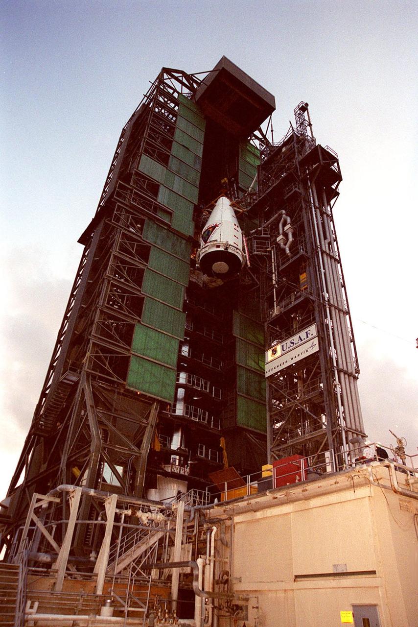
The nose fairing covering the Tracking and Data Relay Satellite (TDRS-H) nears the top of the launch tower at Launch Pad 36A, Cape Canaveral Air Force Station. It will be mated with the Atlas IIA/Centaur rocket, which is already stacked (barely visible behind the framework on lower left), for launch on June 29. The satellite will augment the TDRS system’s existing Sand Ku-band frequencies by adding Ka-band capability. TDRS will serve as the sole means of continuous, high-data-rate communication with the Space Shuttle, with the International Space Station upon its completion, and with dozens of unmanned scientific satellites in low earth orbit
An overhead crane is positioned on the nose fairing covering the Tracking and Data Relay Satellite (TDRS-H) in order to lift it up the tower at Launch Pad 36A, Cape Canaveral Air Force Station. It will be mated with the Atlas IIA/Centaur rocket, which is already stacked, for launch on June 29. The satellite will augment the TDRS system’s existing Sand Ku-band frequencies by adding Ka-band capability. TDRS will serve as the sole means of continuous, high-data-rate communication with the Space Shuttle, with the International Space Station upon its completion, and with dozens of unmanned scientific satellites in low earth orbit
In the early morning hours on Launch Pad 36A, Cape Canaveral Air Force Station, the tower rolls back from NASA’s Tracking and Data Relay Satellite (TDRS-H) before liftoff atop an Atlas IIA/Centaur rocket. One of three satellites (labeled H, I and J) being built by the Hughes Space and Communications Company, the latest TDRS uses an innovative springback antenna design. A pair of 15-foot-diameter, flexible mesh antenna reflectors fold up for launch, then spring back into their original cupped circular shape on orbit. The new satellites will augment the TDRS system’s existing Sand Ku-band frequencies by adding Ka-band capability. TDRS will serve as the sole means of continuous, high-data-rate communication with the Space Shuttle, with the International Space Station upon its completion, and with dozens of unmanned scientific satellites in low earth orbit
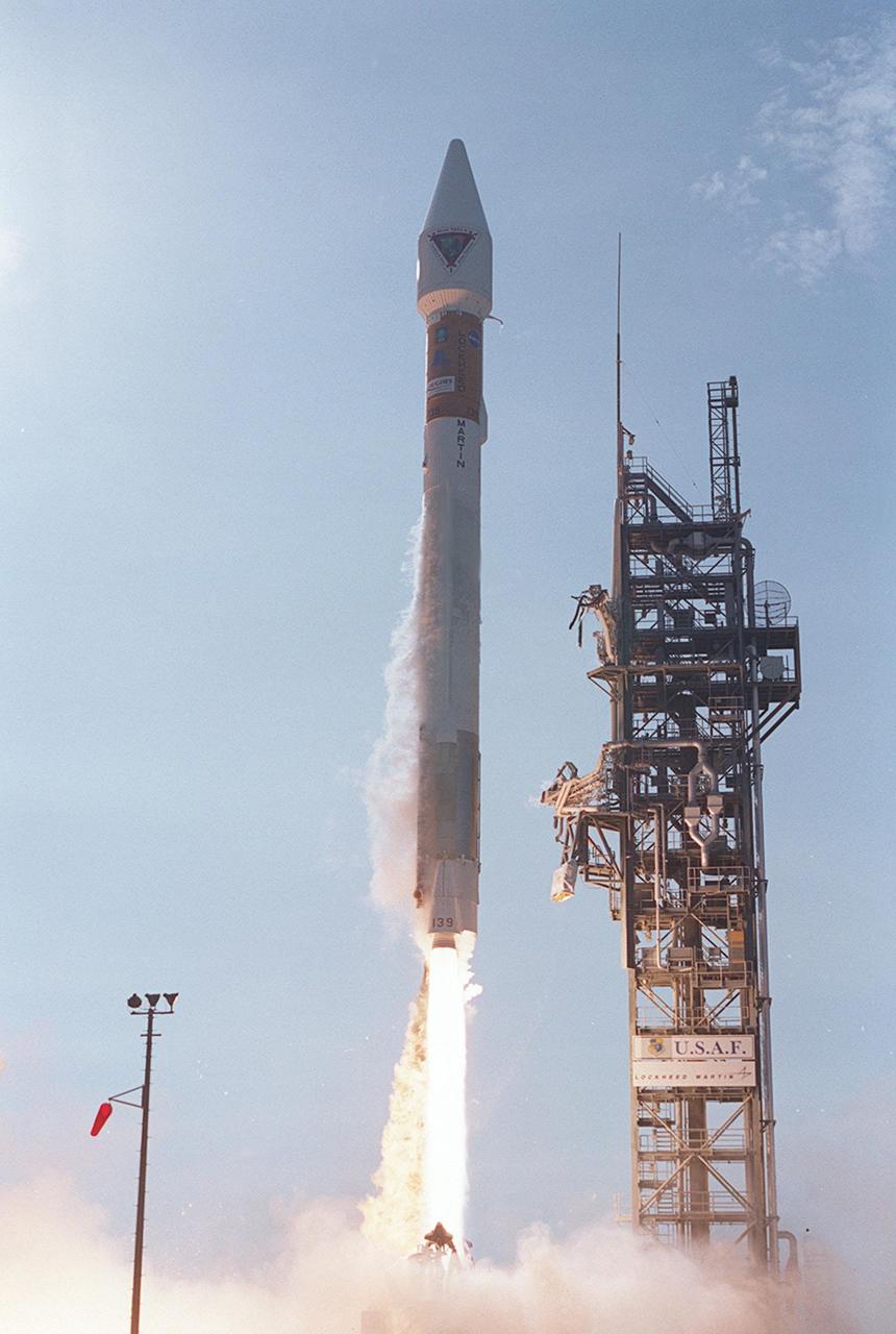
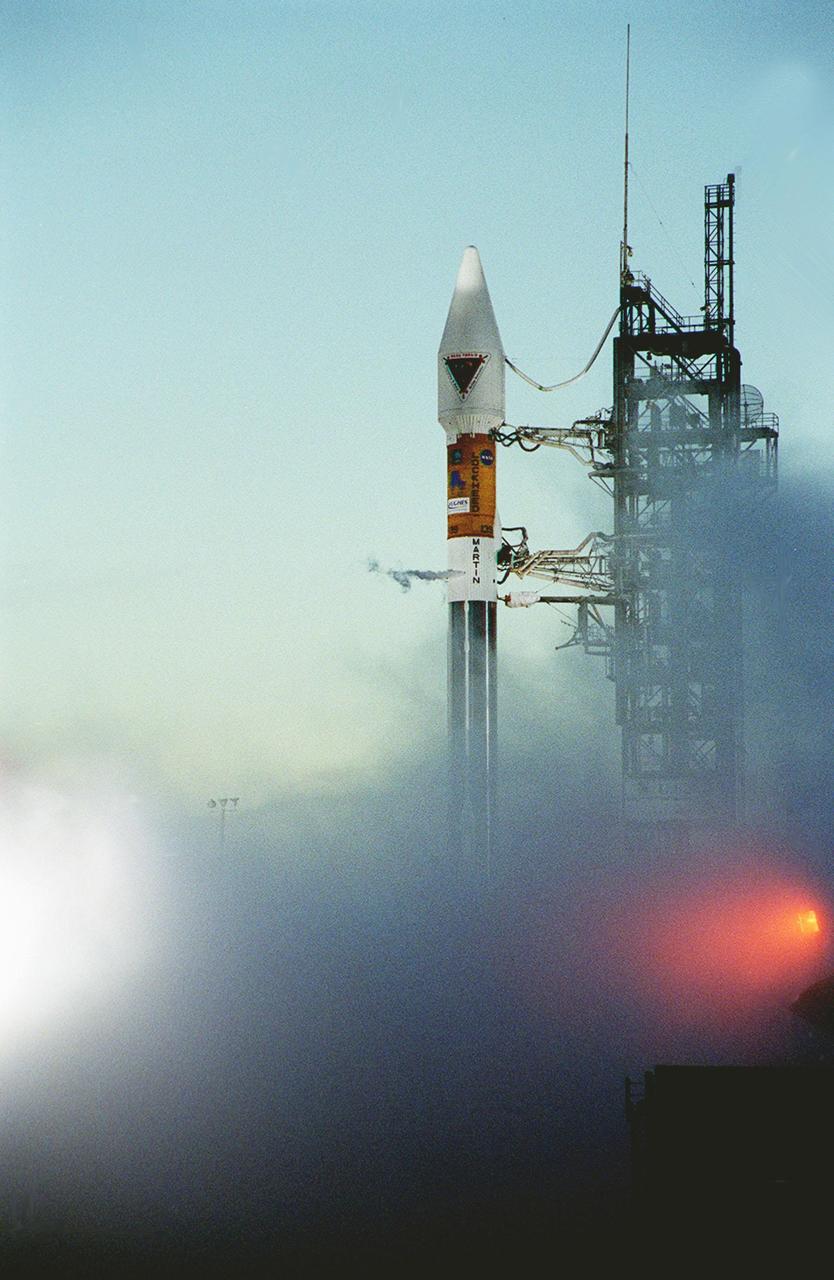
Looking like a Roman candle, NASA’s Tracking and Data Relay Satellite (TDRS-H) shoots into the blue sky aboard an Atlas IIA/Centaur rocket from Pad 36A, Cape Canaveral Air Force Station. Liftoff occurred at 8:56 a.m. EDT. One of three satellites (labeled H, I and J) being built by the Hughes Space and Communications Company, the latest TDRS uses an innovative springback antenna design. A pair of 15-foot-diameter, flexible mesh antenna reflectors fold up for launch, then spring back into their original cupped circular shape on orbit. The new satellites will augment the TDRS system’s existing Sand Ku-band frequencies by adding Ka-band capability. TDRS will serve as the sole means of continuous, high-data-rate communication with the space shuttle, with the International Space Station upon its completion, and with dozens of unmanned scientific satellites in low earth orbit
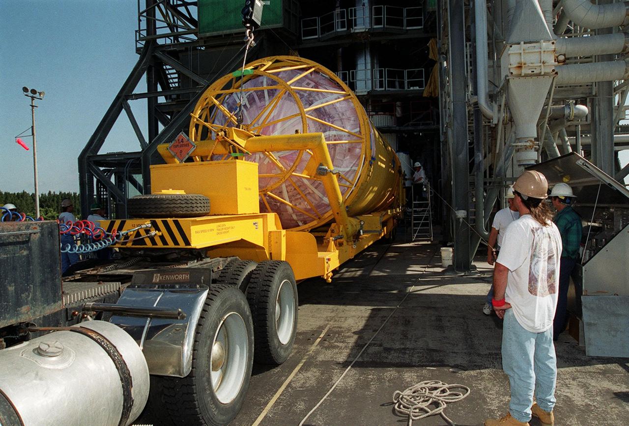
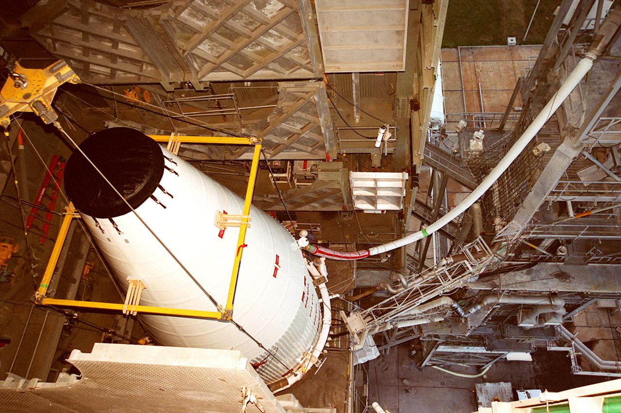
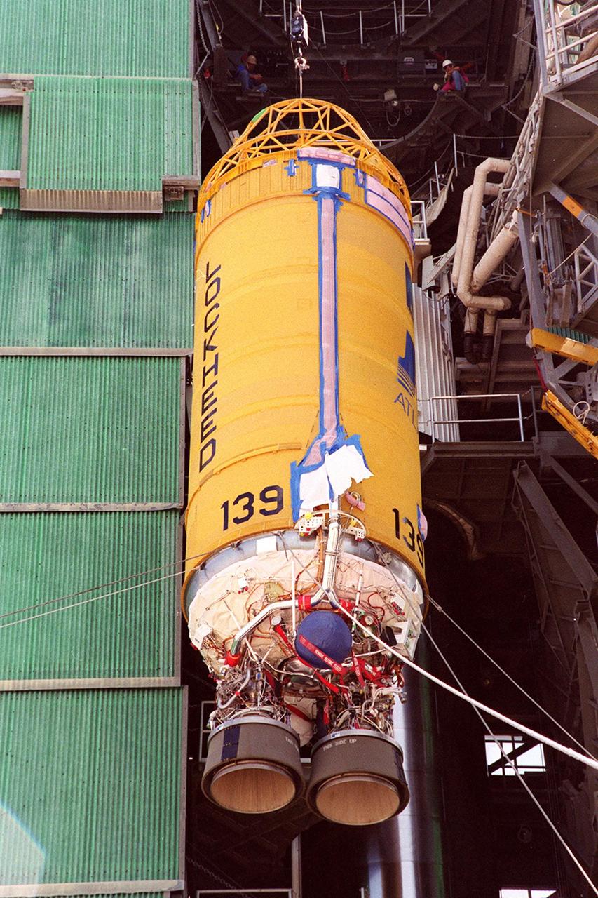
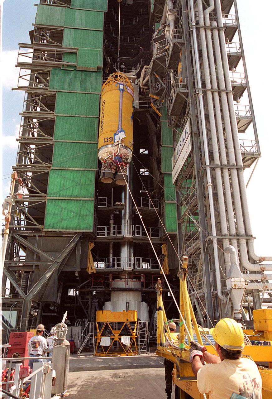
At Launch Pad 36A, Cape Canaveral Air Force Station, a Centaur rocket arrives for mating with the Atlas IIA rocket already in the tower. The Centaur upper stage is 10.0 m (33-ft) long and 3.05 m (10 ft) in diameter. The Lockheed-built Atlas IIA/Centaur rocket will launch the latest Tracking and Data Relay Satellite (TDRS) June 29 from CCAFS. The TDRS is one of three (labeled H, I and J) being built in the Hughes Space and Communications Company Integrated Satellite Factory in El Segundo, Calif. The new satellites will augment the TDRS system’s existing Sand Ku-band frequencies by adding Ka-band capability. TDRS will serve as the sole means of continuous, high-data-rate communication with the space shuttle, with the International Space Station upon its completion, and with dozens of unmanned scientific satellites in low earth orbit
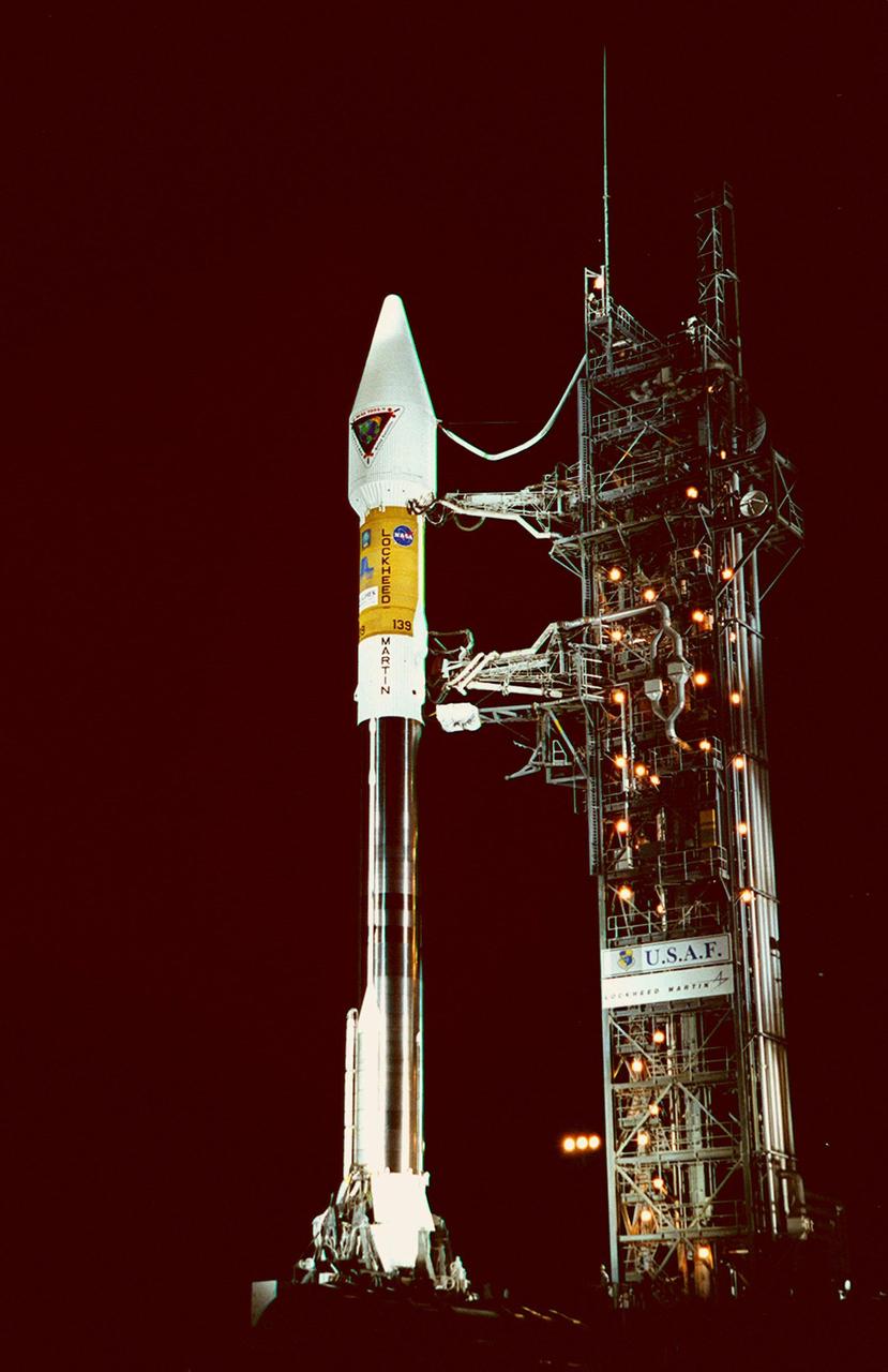
After tower rollback just before dawn on Launch Pad 36A, Cape Canaveral Air Force Station, NASA’s Tracking and Data Relay Satellite (TDRS-H) sits bathed in spotlights before liftoff atop an Atlas IIA/Centaur rocket. One of three satellites (labeled H, I and J) being built by the Hughes Space and Communications Company, the latest TDRS uses an innovative springback antenna design. A pair of 15-foot-diameter, flexible mesh antenna reflectors fold up for launch, then spring back into their original cupped circular shape on orbit. The new satellites will augment the TDRS system’s existing Sand Ku-band frequencies by adding Ka-band capability. TDRS will serve as the sole means of continuous, high-data-rate communication with the Space Shuttle, with the International Space Station upon its completion, and with dozens of unmanned scientific satellites in low earth orbit
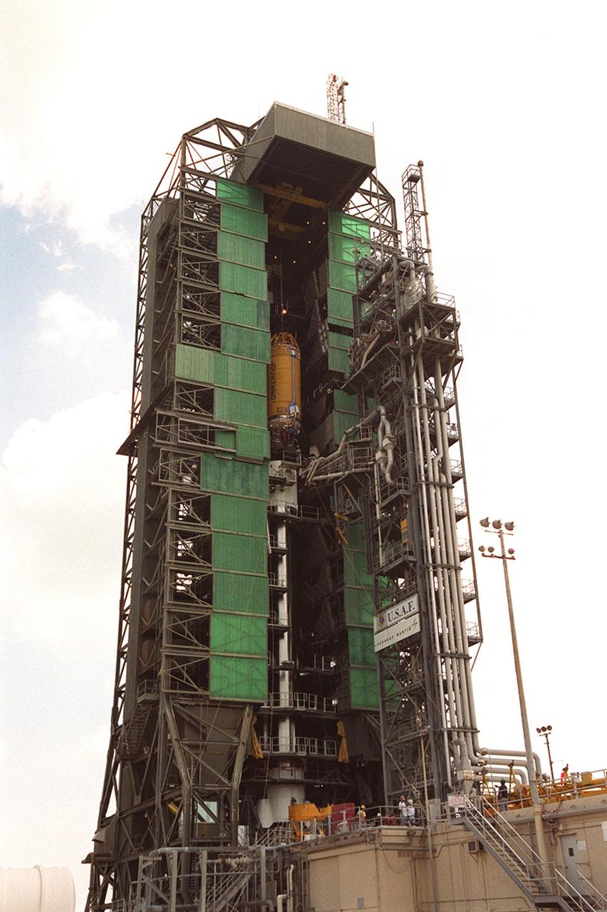
In this long view of the launch tower at Pad 36A, Cape Canaveral Air Force Station, the upper stage Centaur rocket can be seen as it rises up the tower to be mated to the lower stage Atlas IIA rocket already there. The Lockheed-built Atlas IIA/Centaur rocket will launch the latest Tracking and Data Relay Satellite (TDRS) June 29 from CCAFS. The TDRS is one of three (labeled H, I and J) being built in the Hughes Space and Communications Company Integrated Satellite Factory in El Segundo, Calif. The new satellites will augment the TDRS system’s existing Sand Ku-band frequencies by adding Ka-band capability. TDRS will serve as the sole means of continuous, high-data-rate communication with the space shuttle, with the International Space Station upon its completion, and with dozens of unmanned scientific satellites in low earth orbit
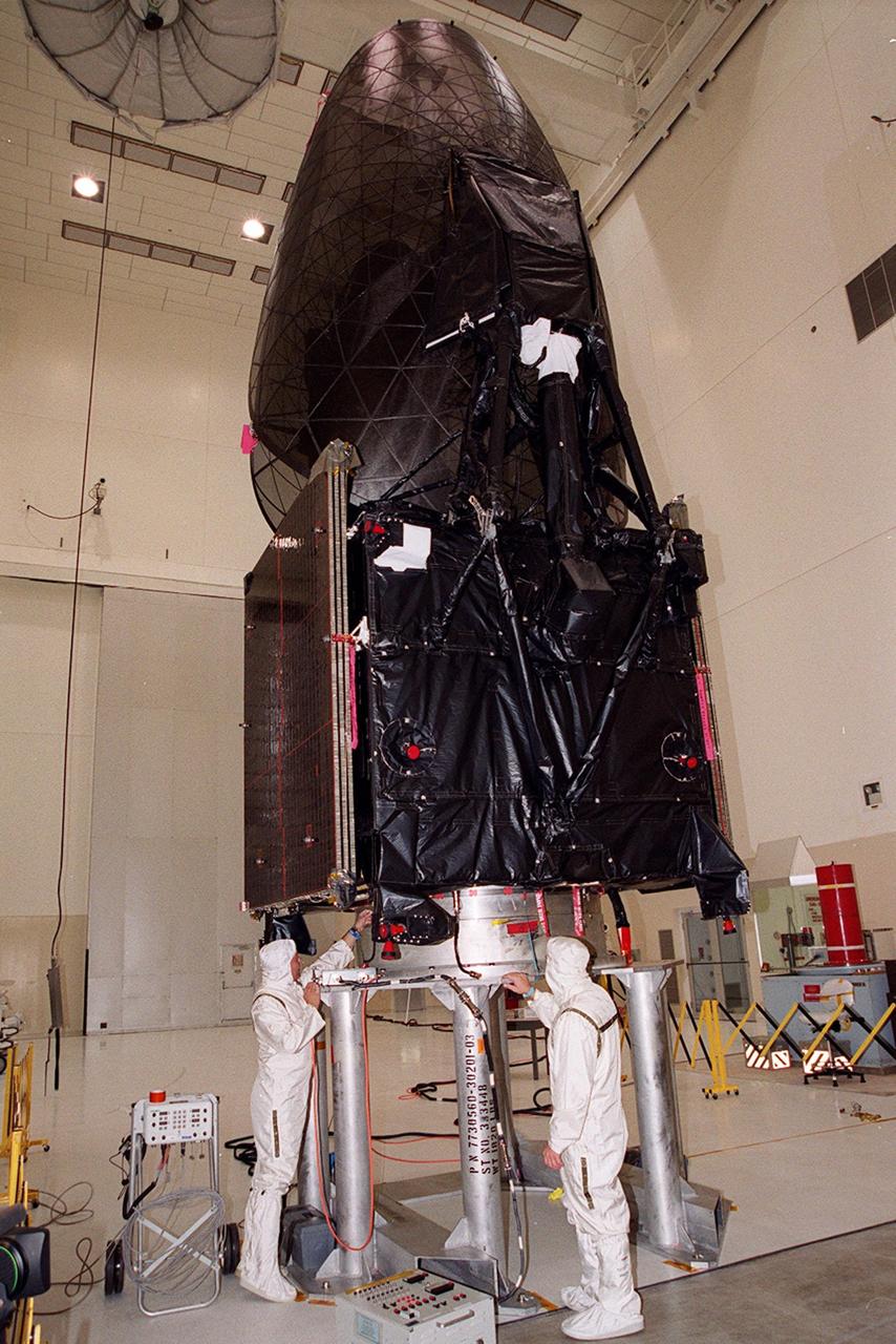
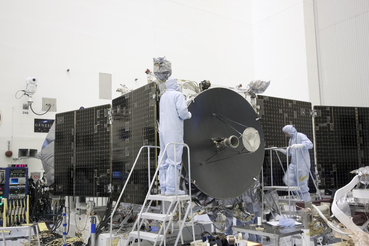
CAPE CANAVERAL, Fla. – Inside the Payload Hazardous Servicing Facility at NASA's Kennedy Space Center in Florida, engineers and technicians install a radome over the antenna for the Mars Atmosphere and Volatile Evolution, or MAVEN, spacecraft. The radome is a coated kapton cover providing thermal protection for the high gain antenna while not interfering with radio frequency transmissions from the spacecraft. MAVEN is being prepared for its scheduled launch in November from Cape Canaveral Air Force Station, Fla. atop a United Launch Alliance Atlas V rocket. Positioned in an orbit above the Red Planet, MAVEN will study the upper atmosphere of Mars in unprecedented detail. For more information, visit: http://www.nasa.gov/mission_pages/maven/main/index.html Photo credit: NASA/Jim Grossmann

NASA’s Tracking and Data Relay Satellite (TDRS-H) rises into the blue sky from Pad 36A, Cape Canaveral Air Force Station. Liftoff occurred at 8:56 a.m. EDT aboard an Atlas IIA/Centaur rocket. One of three satellites (labeled H, I and J) being built by the Hughes Space and Communications Company, the latest TDRS uses an innovative springback antenna design. A pair of 15-foot-diameter, flexible mesh antenna reflectors fold up for launch, then spring back into their original cupped circular shape on orbit. The new satellites will augment the TDRS system’s existing Sand Ku-band frequencies by adding Ka-band capability. TDRS will serve as the sole means of continuous, high-data-rate communication with the space shuttle, with the International Space Station upon its completion, and with dozens of unmanned scientific satellites in low earth orbit
CAPE CANAVERAL, Fla. -- In the Space Station Processing Facility at NASA's Kennedy Space Center in Florida, the ICS Exposed Facility, or ICS-EF, is moved across the floor to the Japanese Experiment Module's Experiment Logistics Module-Exposed Section, or ELM-ES, where it will be installed alongside two other payloads, the SEDA-AP (Space Environment Data Acquisition Equipment-Attached Payload) and MAXI (Monitor of All-sky X-ray Image), already installed. The ICS-EF is composed of several components, including an antenna, pointing mechanism, frequency converters, high-power amplifier and various sensors including the Earth sensor, Sun sensor and inertial reference unit. The ICS-EF is part of space shuttle Endeavour's payload on the STS-127 mission, targeted for launch on May 15. Photo credit: NASA/Jim Grossmann
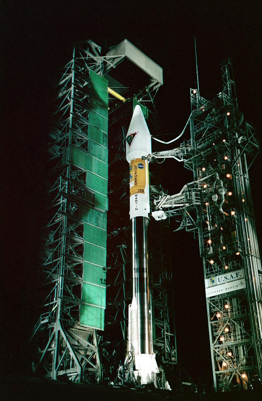
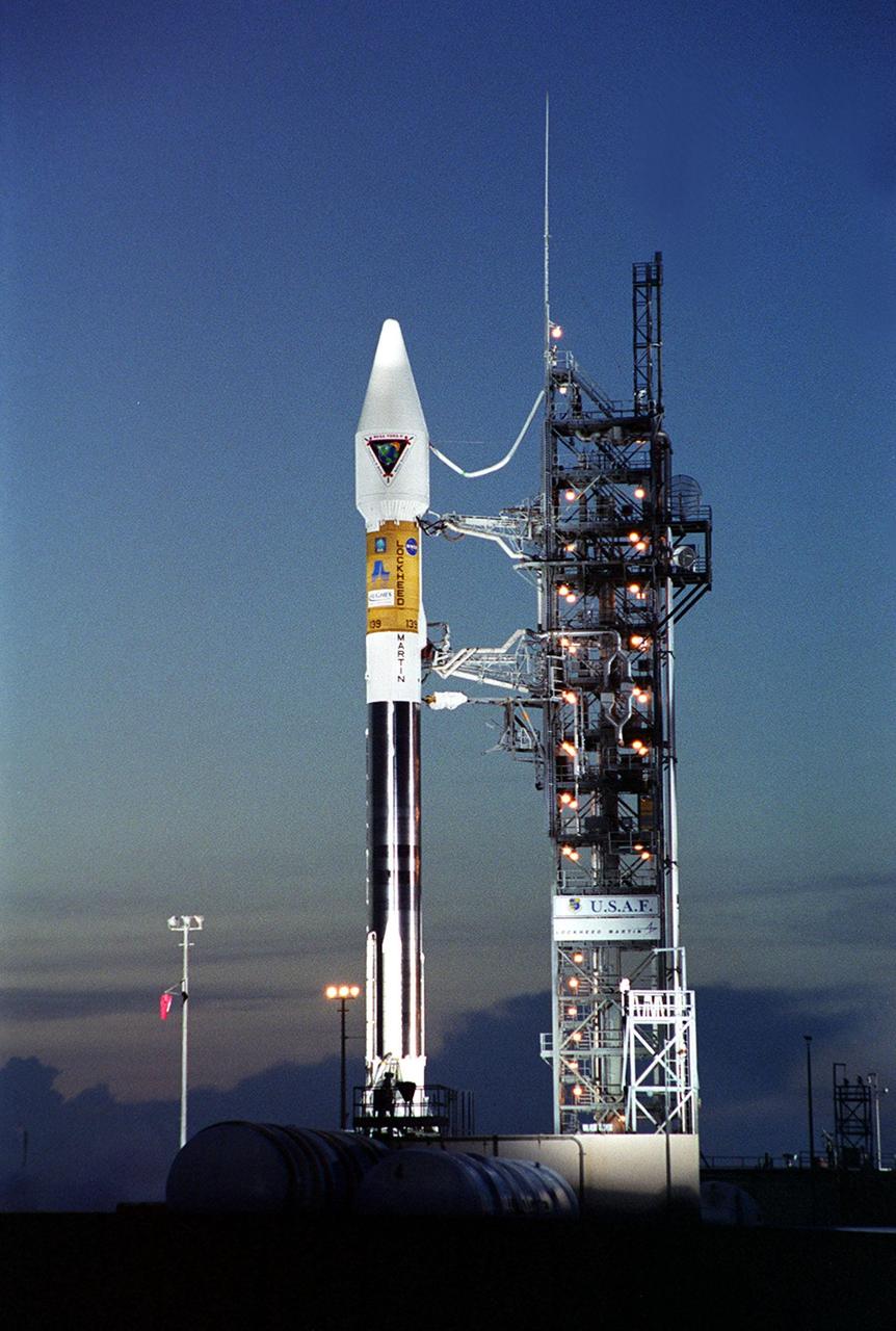
NASA’s Tracking and Data Relay Satellite (TDRS-H) sits poised on Launch Pad 36A, Cape Canaveral Air Force Station, before its scheduled launch aboard an Atlas IIA/Centaur rocket. One of three satellites (labeled H, I and J) being built by the Hughes Space and Communications Company, the latest TDRS uses an innovative springback antenna design. A pair of 15-foot-diameter, flexible mesh antenna reflectors fold up for launch, then spring back into their original cupped circular shape on orbit. The new satellites will augment the TDRS system’s existing Sand Ku-band frequencies by adding Ka-band capability. TDRS will serve as the sole means of continuous, high-data-rate communication with the space shuttle, with the International Space Station upon its completion, and with dozens of unmanned scientific satellites in low earth orbit

Looking like a Roman candle, NASA’s Tracking and Data Relay Satellite (TDRS-H) shoots into the blue sky aboard an Atlas IIA/Centaur rocket from Pad 36A, Cape Canaveral Air Force Station. Liftoff occurred at 8:56 a.m. EDT. One of three satellites (labeled H, I and J) being built by the Hughes Space and Communications Company, the latest TDRS uses an innovative springback antenna design. A pair of 15-foot-diameter, flexible mesh antenna reflectors fold up for launch, then spring back into their original cupped circular shape on orbit. The new satellites will augment the TDRS system’s existing Sand Ku-band frequencies by adding Ka-band capability. TDRS will serve as the sole means of continuous, high-data-rate communication with the space shuttle, with the International Space Station upon its completion, and with dozens of unmanned scientific satellites in low earth orbit

NASA’s Tracking and Data Relay Satellite (TDRS-H) rises into the blue sky from Pad 36A, Cape Canaveral Air Force Station. Liftoff occurred at 8:56 a.m. EDT aboard an Atlas IIA/Centaur rocket. One of three satellites (labeled H, I and J) being built by the Hughes Space and Communications Company, the latest TDRS uses an innovative springback antenna design. A pair of 15-foot-diameter, flexible mesh antenna reflectors fold up for launch, then spring back into their original cupped circular shape on orbit. The new satellites will augment the TDRS system’s existing Sand Ku-band frequencies by adding Ka-band capability. TDRS will serve as the sole means of continuous, high-data-rate communication with the space shuttle, with the International Space Station upon its completion, and with dozens of unmanned scientific satellites in low earth orbit
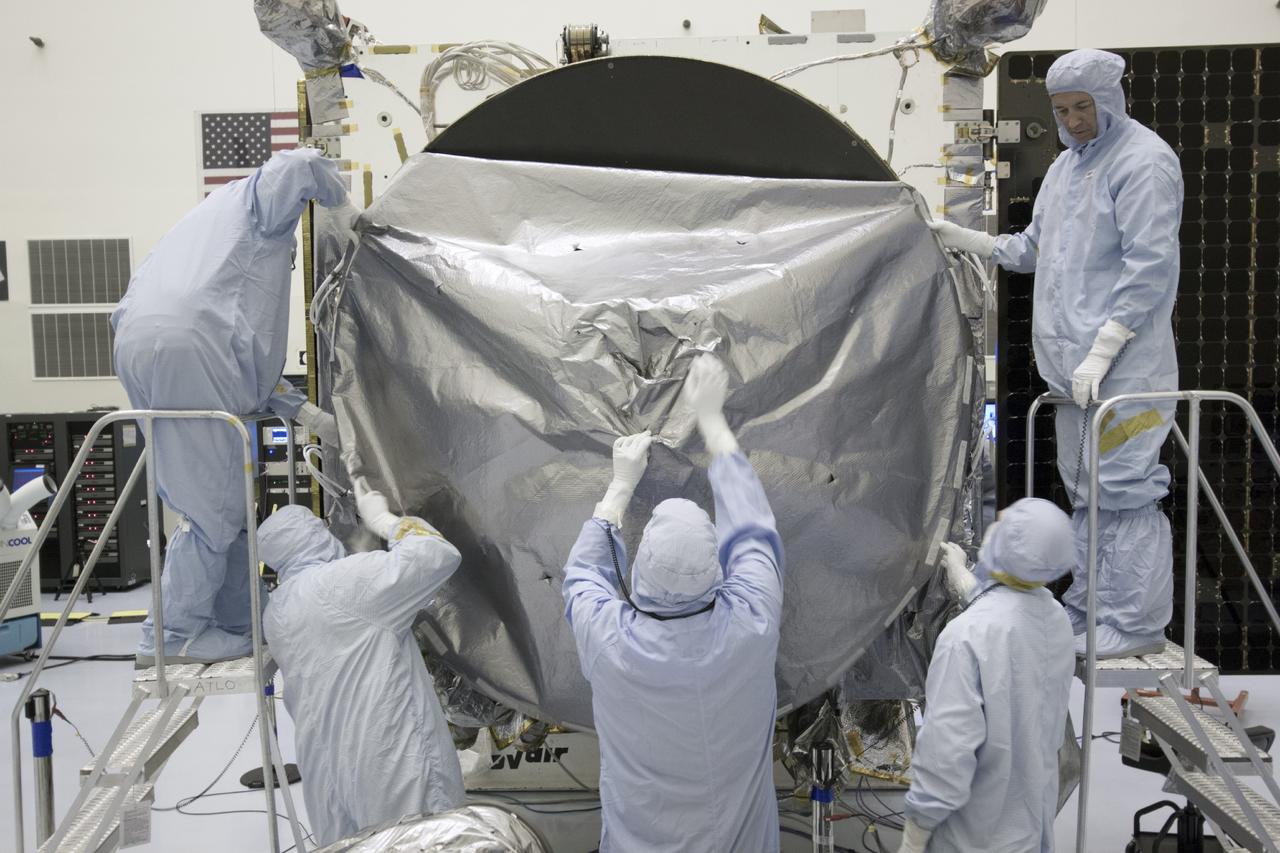
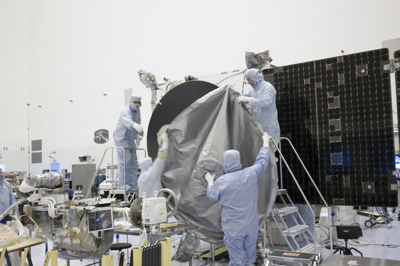
CAPE CANAVERAL, Fla. – Inside the Payload Hazardous Servicing Facility at NASA's Kennedy Space Center in Florida, engineers and technicians prepare to install a radome over the antenna for the Mars Atmosphere and Volatile Evolution, or MAVEN, spacecraft. The radome is a coated kapton cover providing thermal protection for the high gain antenna while not interfering with radio frequency transmissions from the spacecraft. MAVEN is being prepared for its scheduled launch in November from Cape Canaveral Air Force Station, Fla. atop a United Launch Alliance Atlas V rocket. Positioned in an orbit above the Red Planet, MAVEN will study the upper atmosphere of Mars in unprecedented detail. For more information, visit: http://www.nasa.gov/mission_pages/maven/main/index.html Photo credit: NASA/Jim Grossmann
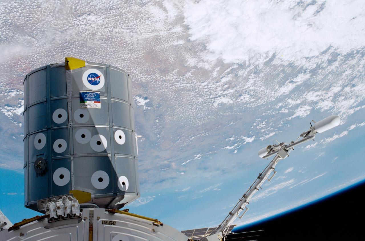
STS100-398-017 (19 April-1 May 2001) --- Backdropped by the Earth with partial cloud cover, the Raffaello Multi-Purpose Logistics Module (MPLM) and the Ultra High Frequency (UHF) antenna are photographed by a crewmember during this STS-100 mission to the International Space Station (ISS). The Raffaello, which was built by the Italian Space Agency (ASI), is the second of three such pressurized modules that will serve as ISS "moving vans", carrying laboratory racks filled with equipment, experiments and supplies to and from the station aboard the space shuttle. The UHF antenna was attached to the station's U.S. Laboratory Destiny by space walking astronauts Chris A. Hadfield and Scott E. Parazynski during the mission's first spacewalk. The antenna, on a 1.2-meter (4-foot) boom, is part of the UHF Communications Subsystem of the station. It will interact with systems already aboard the station, including the Space-to-Space Station Radio transceivers. A second antenna will be delivered on the STS-115/11A next year.
Workers in KSC’s Spacecraft Assembly and Encapsulation Facility (SAEF-2) conduct electrical testing on the Tracking and Data Relay Satellite (TDRS-H) above them. The TDRS is scheduled to be launched from CCAFS June 29 aboard an Atlas IIA/Centaur rocket. One of three satellites (labeled H, I and J) being built in the Hughes Space and Communications Company Integrated Satellite Factory in El Segundo, Calif., the latest TDRS uses an innovative springback antenna design. A pair of 15-foot-diameter, flexible mesh antenna reflectors fold up for launch, then spring back into their original cupped circular shape on orbit. The new satellites will augment the TDRS system’s existing Sand Ku-band frequencies by adding Ka-band capability. TDRS will serve as the sole means of continuous, high-data-rate communication with the space shuttle, with the International Space Station upon its completion, and with dozens of unmanned scientific satellites in low earth orbit
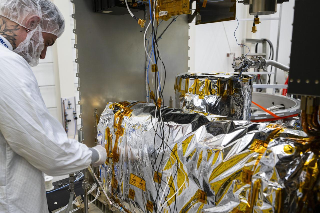
jsc2025e015677 (3/6/2025) --- The closure of the instrument panel of the Atomic Clock Ensemble in Space (ACES) has taken place at Airbus Friedrichshafen, Germany. ACES is an ESA instrument that tests fundamental physics, such as Einstein’s theory of general relativity, from the International Space Station. According to this theory, gravity affects the passing of time—time flies faster at the top of Mount Everest than at sea level. This effect has been proven in experiments on Earth, and ACES will make more precise measurements of this phenomenon and other fundamental physics such as the standard model of particle physics, as it flies 400 km high on the space station. ACES contains two clocks: PHARAO, a caesium atomic clock developed by the French Space Agency CNES, and the Space Hydrogen Maser developed by Spectratime, which uses hydrogen atoms as a frequency reference. The payload will be externally mounted to ESA’s Columbus laboratory on the space station. Image courtesy of S. Corvaja (ESA).

After tower rollback just before dawn on Launch Pad 36A, Cape Canaveral Air Force Station, NASA’s Tracking and Data Relay Satellite (TDRS-H) sits bathed in spotlights before liftoff atop an Atlas IIA/Centaur rocket. One of three satellites (labeled H, I and J) being built by the Hughes Space and Communications Company, the latest TDRS uses an innovative springback antenna design. A pair of 15-foot-diameter, flexible mesh antenna reflectors fold up for launch, then spring back into their original cupped circular shape on orbit. The new satellites will augment the TDRS system’s existing Sand Ku-band frequencies by adding Ka-band capability. TDRS will serve as the sole means of continuous, high-data-rate communication with the Space Shuttle, with the International Space Station upon its completion, and with dozens of unmanned scientific satellites in low earth orbit
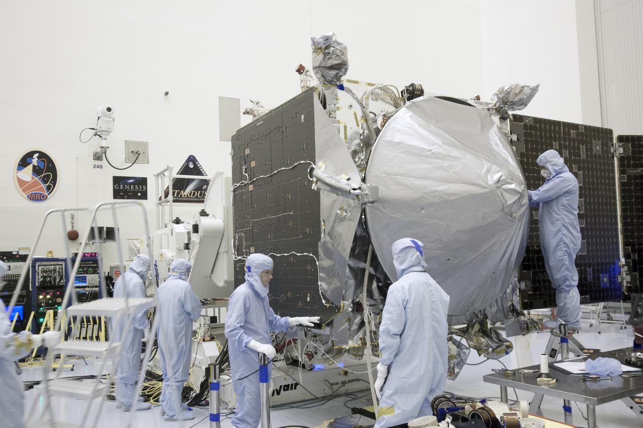
CAPE CANAVERAL, Fla. – Inside the Payload Hazardous Servicing Facility at NASA's Kennedy Space Center in Florida, engineers and technicians install a radome over the antenna for the Mars Atmosphere and Volatile Evolution, or MAVEN, spacecraft. The radome is a coated kapton cover providing thermal protection for the high gain antenna while not interfering with radio frequency transmissions from the spacecraft. MAVEN is being prepared for its scheduled launch in November from Cape Canaveral Air Force Station, Fla. atop a United Launch Alliance Atlas V rocket. Positioned in an orbit above the Red Planet, MAVEN will study the upper atmosphere of Mars in unprecedented detail. For more information, visit: http://www.nasa.gov/mission_pages/maven/main/index.html Photo credit: NASA/Jim Grossmann

In the early morning hours, NASA’s Tracking and Data Relay Satellite (TDRS-H) sits poised on Launch Pad 36A, Cape Canaveral Air Force Station, before its scheduled launch aboard an Atlas IIA/Centaur rocket. One of three satellites (labeled H, I and J) being built by the Hughes Space and Communications Company, the latest TDRS uses an innovative springback antenna design. A pair of 15-foot-diameter, flexible mesh antenna reflectors fold up for launch, then spring back into their original cupped circular shape on orbit. The new satellites will augment the TDRS system’s existing Sand Ku-band frequencies by adding Ka-band capability. TDRS will serve as the sole means of continuous, high-data-rate communication with the Space Shuttle, with the International Space Station upon its completion, and with dozens of unmanned scientific satellites in low earth orbit

In the early morning hours on Launch Pad 36A, Cape Canaveral Air Force Station, the tower rolls back from NASA’s Tracking and Data Relay Satellite (TDRS-H) before liftoff atop an Atlas IIA/Centaur rocket. One of three satellites (labeled H, I and J) being built by the Hughes Space and Communications Company, the latest TDRS uses an innovative springback antenna design. A pair of 15-foot-diameter, flexible mesh antenna reflectors fold up for launch, then spring back into their original cupped circular shape on orbit. The new satellites will augment the TDRS system’s existing Sand Ku-band frequencies by adding Ka-band capability. TDRS will serve as the sole means of continuous, high-data-rate communication with the Space Shuttle, with the International Space Station upon its completion, and with dozens of unmanned scientific satellites in low earth orbit

At Launch Pad 36A, Cape Canaveral Air Force Station, a Centaur rocket is raised to a vertical position before lifting it up the launch tower. It will be mated with the lower stage Atlas IIA rocket, already in the tower, to launch the latest Tracking and Data Relay Satellite (TDRS) June 29 from CCAFS. The TDRS is one of three (labeled H, I and J) being built in the Hughes Space and Communications Company Integrated Satellite Factory in El Segundo, Calif. The new satellites will augment the TDRS system’s existing Sand Ku-band frequencies by adding Ka-band capability. TDRS will serve as the sole means of continuous, high-data-rate communication with the space shuttle, with the International Space Station upon its completion, and with dozens of unmanned scientific satellites in low earth orbit
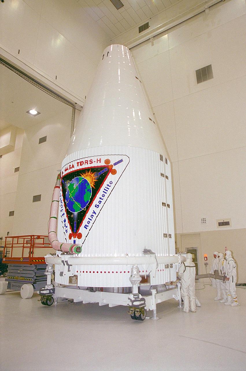
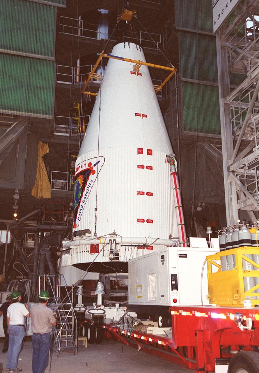
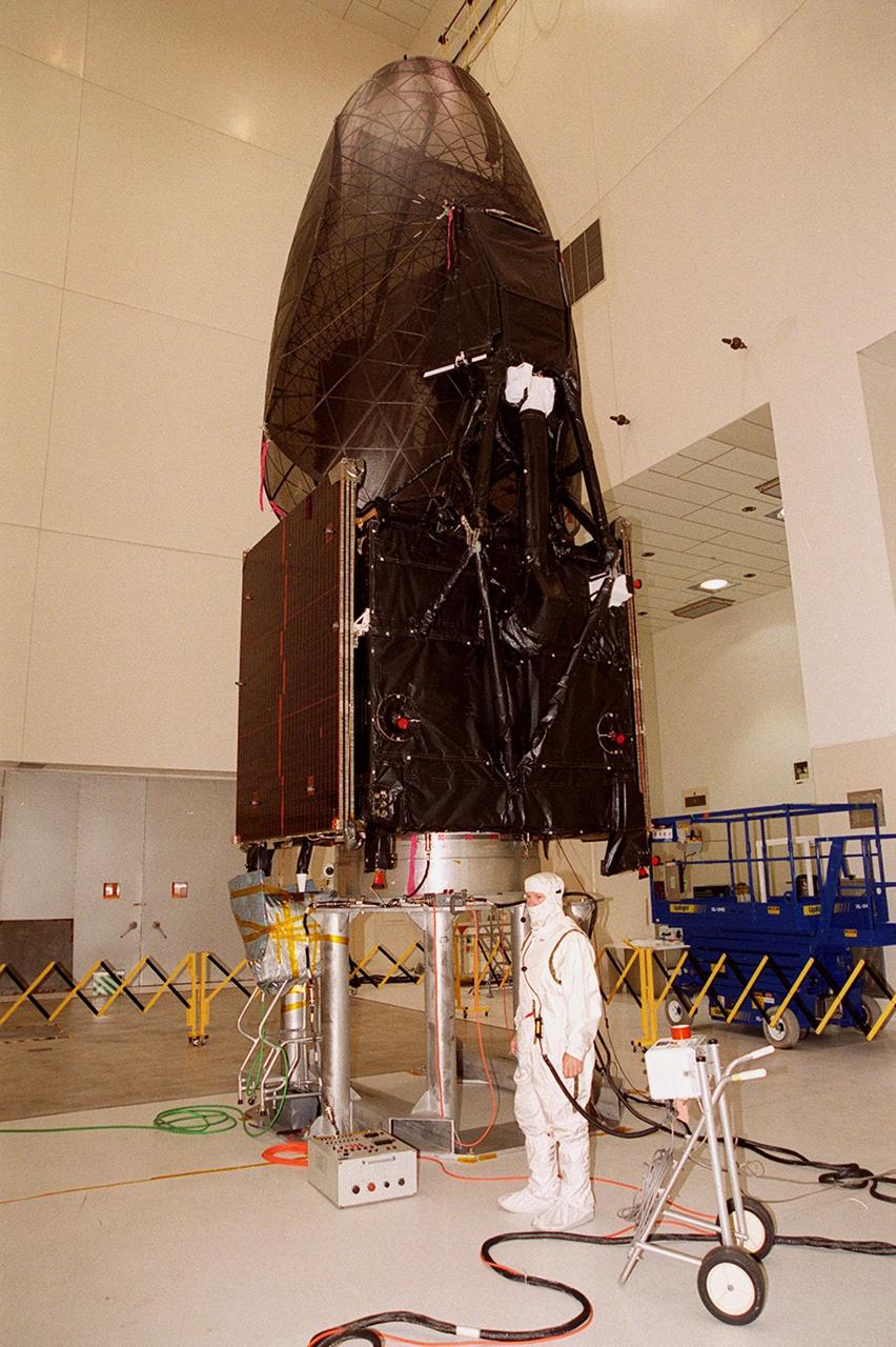
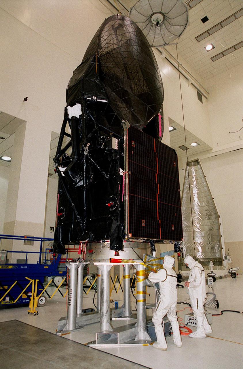
The Tracking and Data Relay Satellite (TDRS-H) sits fully encapsulated inside the fairing. Next, it will be transported to Launch Pad 36A, Cape Canaveral Air Force Station for launch scheduled June 29 aboard an Atlas IIA/Centaur rocket. One of three satellites (labeled H, I and J) being built in the Hughes Space and Communications Company Integrated Satellite Factory in El Segundo, Calif., the latest TDRS uses an innovative springback antenna design. A pair of 15-foot-diameter, flexible mesh antenna reflectors fold up for launch, then spring back into their original cupped circular shape on orbit. The new satellites will augment the TDRS system’s existing Sand Ku-band frequencies by adding Ka-band capability. TDRS will serve as the sole means of continuous, high-data-rate communication with the space shuttle, with the International Space Station upon its completion, and with dozens of unmanned scientific satellites in low earth orbit

Leaving billowing clouds of steam and smoke behind, NASA’s Tracking and Data Relay Satellite (TDRS-H) shoots into the blue sky aboard an Atlas IIA/Centaur rocket from Pad 36A, Cape Canaveral Air Force Station. Liftoff occurred at 8:56 a.m. EDT. One of three satellites (labeled H, I and J) being built by the Hughes Space and Communications Company, the latest TDRS uses an innovative springback antenna design. A pair of 15-foot-diameter, flexible mesh antenna reflectors fold up for launch, then spring back into their original cupped circular shape on orbit. The new satellites will augment the TDRS system’s existing Sand Ku-band frequencies by adding Ka-band capability. TDRS will serve as the sole means of continuous, high-data-rate communication with the space shuttle, with the International Space Station upon its completion, and with dozens of unmanned scientific satellites in low earth orbit
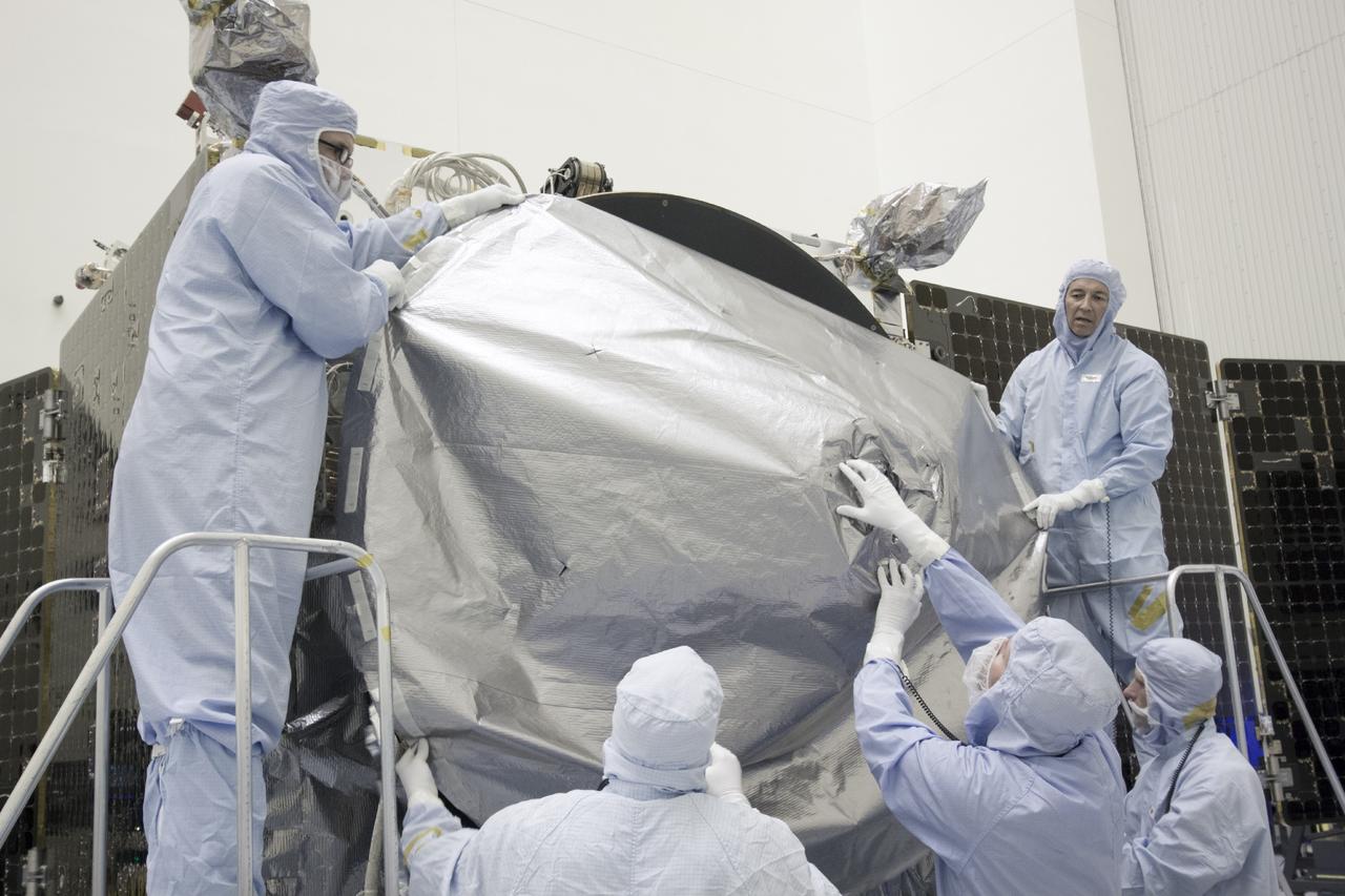
CAPE CANAVERAL, Fla. – Inside the Payload Hazardous Servicing Facility at NASA's Kennedy Space Center in Florida, engineers and technicians install a radome over the antenna for the Mars Atmosphere and Volatile Evolution, or MAVEN, spacecraft. The radome is a coated kapton cover providing thermal protection for the high gain antenna while not interfering with radio frequency transmissions from the spacecraft. MAVEN is being prepared for its scheduled launch in November from Cape Canaveral Air Force Station, Fla. atop a United Launch Alliance Atlas V rocket. Positioned in an orbit above the Red Planet, MAVEN will study the upper atmosphere of Mars in unprecedented detail. For more information, visit: http://www.nasa.gov/mission_pages/maven/main/index.html Photo credit: NASA/Jim Grossmann

At dawn on Launch Pad 36A, Cape Canaveral Air Force Station, an Atlas IIA/Centaur rocket is fueled for launch of NASA’s Tracking and Data Relay Satellite (TDRS-H). One of three satellites (labeled H, I and J) being built by the Hughes Space and Communications Company, the latest TDRS uses an innovative springback antenna design. A pair of 15-foot-diameter, flexible mesh antenna reflectors fold up for launch, then spring back into their original cupped circular shape on orbit. The new satellites will augment the TDRS system’s existing Sand Ku-band frequencies by adding Ka-band capability. TDRS will serve as the sole means of continuous, high-data-rate communication with the Space Shuttle, with the International Space Station upon its completion, and with dozens of unmanned scientific satellites in low earth orbit

At Launch Pad 36A, Cape Canaveral Air Force Station, a Centaur rocket arrives for mating with the Atlas IIA rocket already in the tower. The Centaur upper stage is 10.0 m (33-ft) long and 3.05 m (10 ft) in diameter. The Lockheed-built Atlas IIA/Centaur rocket will launch the latest Tracking and Data Relay Satellite (TDRS) June 29 from CCAFS. The TDRS is one of three (labeled H, I and J) being built in the Hughes Space and Communications Company Integrated Satellite Factory in El Segundo, Calif. The new satellites will augment the TDRS system’s existing Sand Ku-band frequencies by adding Ka-band capability. TDRS will serve as the sole means of continuous, high-data-rate communication with the space shuttle, with the International Space Station upon its completion, and with dozens of unmanned scientific satellites in low earth orbit

At Launch Pad 36A, Cape Canaveral Air Force Station, workers guide the ascent of a Centaur rocket up the launch tower where it will be mated with the lower stage Atlas IIA rocket already in the tower. The Lockheed-built Atlas IIA/Centaur rocket will launch the latest Tracking and Data Relay Satellite (TDRS) June 29 from CCAFS. The TDRS is one of three (labeled H, I and J) being built in the Hughes Space and Communications Company Integrated Satellite Factory in El Segundo, Calif. The new satellites will augment the TDRS system’s existing Sand Ku-band frequencies by adding Ka-band capability. TDRS will serve as the sole means of continuous, high-data-rate communication with the space shuttle, with the International Space Station upon its completion, and with dozens of unmanned scientific satellites in low earth orbit
At Launch Pad 36A, Cape Canaveral Air Force Station, lines help guide the ascent of a Centaur rocket up the launch tower where it will be mated with the lower stage Atlas IIA rocket already in the tower. The Lockheed-built Atlas IIA/Centaur rocket will launch the latest Tracking and Data Relay Satellite (TDRS) June 29 from CCAFS. The TDRS is one of three (labeled H, I and J) being built in the Hughes Space and Communications Company Integrated Satellite Factory in El Segundo, Calif. The new satellites will augment the TDRS system’s existing Sand Ku-band frequencies by adding Ka-band capability. TDRS will serve as the sole means of continuous, high-data-rate communication with the space shuttle, with the International Space Station upon its completion, and with dozens of unmanned scientific satellites in low earth orbit
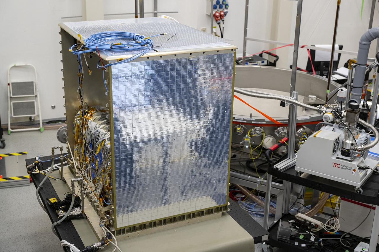
jsc2025e015679 (3/6/2025) --- The closure of the instrument panel of the Atomic Clock Ensemble in Space (ACES) has taken place at Airbus Friedrichshafen, Germany. ACES is an ESA instrument that tests fundamental physics, such as Einstein’s theory of general relativity, from the International Space Station. According to this theory, gravity affects the passing of time—time flies faster at the top of Mount Everest than at sea level. This effect has been proven in experiments on Earth, and ACES will make more precise measurements of this phenomenon and other fundamental physics such as the standard model of particle physics, as it flies 400 km high on the space station. ACES contains two clocks: PHARAO, a caesium atomic clock developed by the French Space Agency CNES, and the Space Hydrogen Maser developed by Spectratime, which uses hydrogen atoms as a frequency reference. The payload will be externally mounted to ESA’s Columbus laboratory on the space station. Image courtesy of S. Corvaja (ESA).
jsc2025e015680 (3/6/2025) --- The closure of the instrument panel of the Atomic Clock Ensemble in Space (ACES) has taken place at Airbus Friedrichshafen, Germany. ACES is an ESA instrument that tests fundamental physics, such as Einstein’s theory of general relativity, from the International Space Station. According to this theory, gravity affects the passing of time—time flies faster at the top of Mount Everest than at sea level. This effect has been proven in experiments on Earth, and ACES will make more precise measurements of this phenomenon and other fundamental physics such as the standard model of particle physics, as it flies 400 km high on the space station. ACES contains two clocks: PHARAO, a caesium atomic clock developed by the French Space Agency CNES, and the Space Hydrogen Maser developed by Spectratime, which uses hydrogen atoms as a frequency reference. The payload will be externally mounted to ESA’s Columbus laboratory on the space station. Image courtesy of S. Corvaja (ESA).
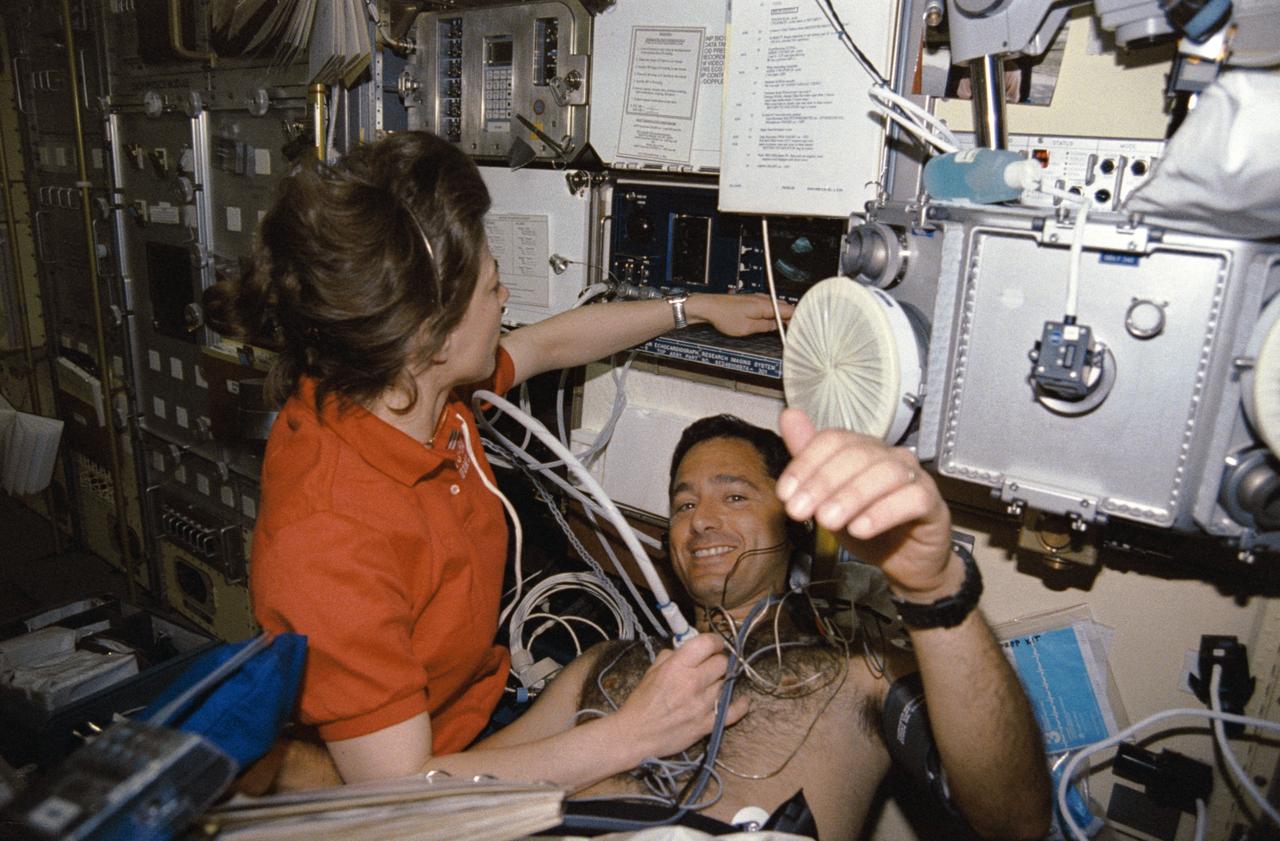
STS050-291-027 (25 June-9 July 1992) --- Astronaut Bonnie J. Dunbar uses a Doppler to collect medical data from Lawrence J. DeLucas, payload specialist, during his diagnostic "run" in the Lower Body Negative Pressure device (LBNP). The Doppler is used to pick up high-frequency sound waves from the surface of the heart, thus producing pictures on the monitor of the American Flight Echocardiograph (AFE). The result of the LBNP procedure is expected to be an increased tolerance of orthostatis - or standing upright - upon return to Earth's gravity. LBNP has been used a number of times in the United States space program, as early as the Skylab missions. STS-50 is the fourth flight of the current collapsible unit. Researchers are refining the LBNP protocol which will be used operationally on future 13 through 16 day missions.
The Tracking and Data Relay Satellite (TDRS-H) sits on a workstand in KSC’s Spacecraft Assembly and Encapsulation Facility (SAEF-2) in order to undergo electrical testing. The TDRS is scheduled to be launched from CCAFS June 29 aboard an Atlas IIA/Centaur rocket. One of three satellites (labeled H, I and J) being built in the Hughes Space and Communications Company Integrated Satellite Factory in El Segundo, Calif., the latest TDRS uses an innovative springback antenna design. A pair of 15-foot-diameter, flexible mesh antenna reflectors fold up for launch, then spring back into their original cupped circular shape on orbit. The new satellites will augment the TDRS system’s existing Sand Ku-band frequencies by adding Ka-band capability. TDRS will serve as the sole means of continuous, high-data-rate communication with the space shuttle, with the International Space Station upon its completion, and with dozens of unmanned scientific satellites in low earth orbit
CAPE CANAVERAL, Fla. – Inside the Payload Hazardous Servicing Facility at NASA's Kennedy Space Center in Florida, engineers and technicians install a radome over the antenna for the Mars Atmosphere and Volatile Evolution, or MAVEN, spacecraft. The radome is a coated kapton cover providing thermal protection for the high gain antenna while not interfering with radio frequency transmissions from the spacecraft. MAVEN is being prepared for its scheduled launch in November from Cape Canaveral Air Force Station, Fla. atop a United Launch Alliance Atlas V rocket. Positioned in an orbit above the Red Planet, MAVEN will study the upper atmosphere of Mars in unprecedented detail. For more information, visit: http://www.nasa.gov/mission_pages/maven/main/index.html Photo credit: NASA/Jim Grossmann
Workers in KSC’s Spacecraft Assembly and Encapsulation Facility (SAEF-2) prepare the Tracking and Data Relay Satellite (TDRS-H) above them for electrical testing. The TDRS is scheduled to be launched from CCAFS June 29 aboard an Atlas IIA/Centaur rocket. One of three satellites (labeled H, I and J) being built in the Hughes Space and Communications Company Integrated Satellite Factory in El Segundo, Calif., the latest TDRS uses an innovative springback antenna design. A pair of 15-foot-diameter, flexible mesh antenna reflectors fold up for launch, then spring back into their original cupped circular shape on orbit. The new satellites will augment the TDRS system’s existing Sand Ku-band frequencies by adding Ka-band capability. TDRS will serve as the sole means of continuous, high-data-rate communication with the space shuttle, with the International Space Station upon its completion, and with dozens of unmanned scientific satellites in low earth orbit

At Launch Pad 36A, Cape Canaveral Air Force Station, workers check out a Centaur rocket for its lift up the launch tower to be mated with the lower stage Atlas IIA rocket already in the tower. The Lockheed-built Atlas IIA/Centaur rocket will launch the latest Tracking and Data Relay Satellite (TDRS) June 29 from CCAFS. The TDRS is one of three (labeled H, I and J) being built in the Hughes Space and Communications Company Integrated Satellite Factory in El Segundo, Calif. The new satellites will augment the TDRS system’s existing Sand Ku-band frequencies by adding Ka-band capability. TDRS will serve as the sole means of continuous, high-data-rate communication with the space shuttle, with the International Space Station upon its completion, and with dozens of unmanned scientific satellites in low earth orbit
In the early morning hours, NASA’s Tracking and Data Relay Satellite (TDRS-H) sits poised on Launch Pad 36A, Cape Canaveral Air Force Station, before its scheduled launch aboard an Atlas IIA/Centaur rocket. One of three satellites (labeled H, I and J) being built by the Hughes Space and Communications Company, the latest TDRS uses an innovative springback antenna design. A pair of 15-foot-diameter, flexible mesh antenna reflectors fold up for launch, then spring back into their original cupped circular shape on orbit. The new satellites will augment the TDRS system’s existing Sand Ku-band frequencies by adding Ka-band capability. TDRS will serve as the sole means of continuous, high-data-rate communication with the Space Shuttle, with the International Space Station upon its completion, and with dozens of unmanned scientific satellites in low earth orbit
CAPE CANAVERAL, Fla. – Inside the Payload Hazardous Servicing Facility at NASA's Kennedy Space Center in Florida, engineers and technicians prepare to install a radome over the antenna for the Mars Atmosphere and Volatile Evolution, or MAVEN, spacecraft. The radome is a coated kapton cover providing thermal protection for the high gain antenna while not interfering with radio frequency transmissions from the spacecraft. MAVEN is being prepared for its scheduled launch in November from Cape Canaveral Air Force Station, Fla. atop a United Launch Alliance Atlas V rocket. Positioned in an orbit above the Red Planet, MAVEN will study the upper atmosphere of Mars in unprecedented detail. For more information, visit: http://www.nasa.gov/mission_pages/maven/main/index.html Photo credit: NASA/Jim Grossmann
At dawn on Launch Pad 36A, Cape Canaveral Air Force Station, an Atlas IIA/Centaur rocket is fueled for launch of NASA’s Tracking and Data Relay Satellite (TDRS-H). One of three satellites (labeled H, I and J) being built by the Hughes Space and Communications Company, the latest TDRS uses an innovative springback antenna design. A pair of 15-foot-diameter, flexible mesh antenna reflectors fold up for launch, then spring back into their original cupped circular shape on orbit. The new satellites will augment the TDRS system’s existing Sand Ku-band frequencies by adding Ka-band capability. TDRS will serve as the sole means of continuous, high-data-rate communication with the Space Shuttle, with the International Space Station upon its completion, and with dozens of unmanned scientific satellites in low earth orbit

The Tracking and Data Relay Satellite (TDRS-H) sits on a workstand in KSC’s Spacecraft Assembly and Encapsulation Facility (SAEF-2) in order to undergo electrical testing. The TDRS is scheduled to be launched from CCAFS June 29 aboard an Atlas IIA/Centaur rocket. One of three satellites (labeled H, I and J) being built in the Hughes Space and Communications Company Integrated Satellite Factory in El Segundo, Calif., the latest TDRS uses an innovative springback antenna design. A pair of 15-foot-diameter, flexible mesh antenna reflectors fold up for launch, then spring back into their original cupped circular shape on orbit. The new satellites will augment the TDRS system’s existing Sand Ku-band frequencies by adding Ka-band capability. TDRS will serve as the sole means of continuous, high-data-rate communication with the space shuttle, with the International Space Station upon its completion, and with dozens of unmanned scientific satellites in low earth orbit
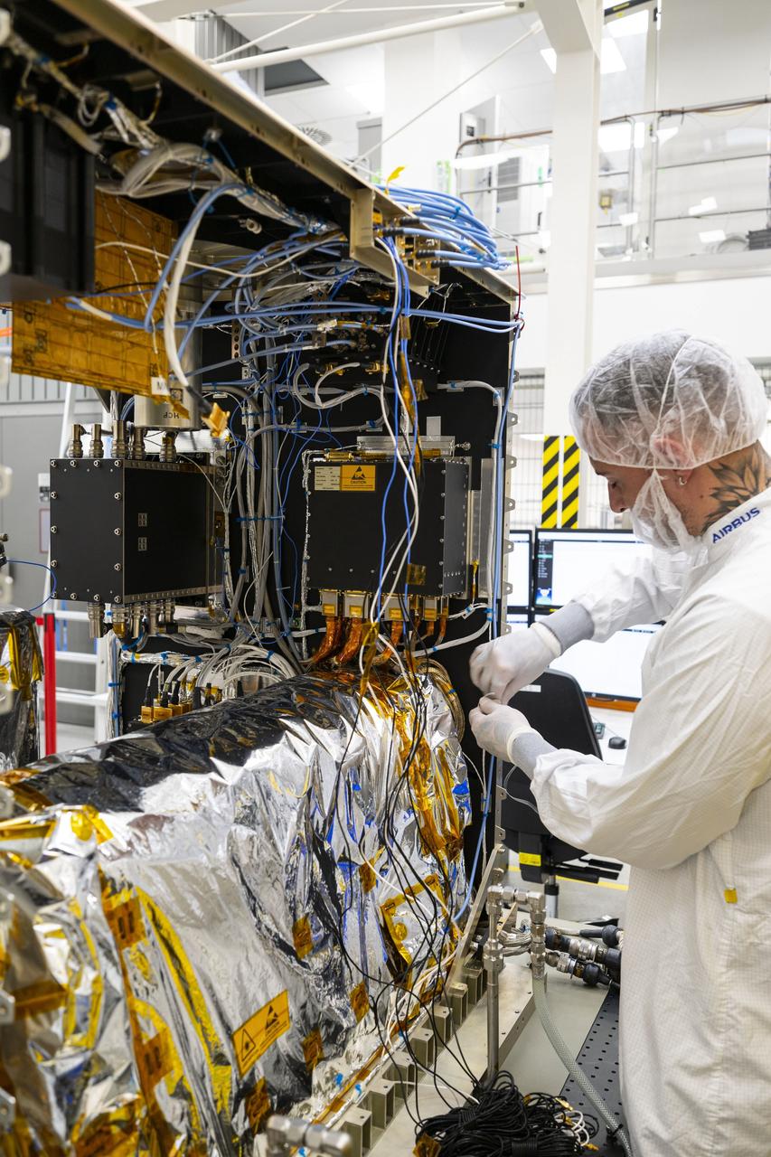
jsc2025e015678 (3/6/2025) --- The closure of the instrument panel of the Atomic Clock Ensemble in Space (ACES) has taken place at Airbus Friedrichshafen, Germany. ACES is an ESA instrument that tests fundamental physics, such as Einstein’s theory of general relativity, from the International Space Station. According to this theory, gravity affects the passing of time—time flies faster at the top of Mount Everest than at sea level. This effect has been proven in experiments on Earth, and ACES will make more precise measurements of this phenomenon and other fundamental physics such as the standard model of particle physics, as it flies 400 km high on the space station. ACES contains two clocks: PHARAO, a caesium atomic clock developed by the French Space Agency CNES, and the Space Hydrogen Maser developed by Spectratime, which uses hydrogen atoms as a frequency reference. The payload will be externally mounted to ESA’s Columbus laboratory on the space station. Image courtesy of S. Corvaja (ESA).
At Launch Pad 36A, Cape Canaveral Air Force Station, workers guide the ascent of a Centaur rocket up the launch tower where it will be mated with the lower stage Atlas IIA rocket already in the tower. The Lockheed-built Atlas IIA/Centaur rocket will launch the latest Tracking and Data Relay Satellite (TDRS) June 29 from CCAFS. The TDRS is one of three (labeled H, I and J) being built in the Hughes Space and Communications Company Integrated Satellite Factory in El Segundo, Calif. The new satellites will augment the TDRS system’s existing Sand Ku-band frequencies by adding Ka-band capability. TDRS will serve as the sole means of continuous, high-data-rate communication with the space shuttle, with the International Space Station upon its completion, and with dozens of unmanned scientific satellites in low earth orbit

Workers in KSC’s Spacecraft Assembly and Encapsulation Facility (SAEF-2) prepare the Tracking and Data Relay Satellite (TDRS-H) above them for electrical testing. The TDRS is scheduled to be launched from CCAFS June 29 aboard an Atlas IIA/Centaur rocket. One of three satellites (labeled H, I and J) being built in the Hughes Space and Communications Company Integrated Satellite Factory in El Segundo, Calif., the latest TDRS uses an innovative springback antenna design. A pair of 15-foot-diameter, flexible mesh antenna reflectors fold up for launch, then spring back into their original cupped circular shape on orbit. The new satellites will augment the TDRS system’s existing Sand Ku-band frequencies by adding Ka-band capability. TDRS will serve as the sole means of continuous, high-data-rate communication with the space shuttle, with the International Space Station upon its completion, and with dozens of unmanned scientific satellites in low earth orbit

The Tracking and Data Relay Satellite (TDRS-H) sits fully encapsulated inside the fairing. Next, it will be transported to Launch Pad 36A, Cape Canaveral Air Force Station for launch scheduled June 29 aboard an Atlas IIA/Centaur rocket. One of three satellites (labeled H, I and J) being built in the Hughes Space and Communications Company Integrated Satellite Factory in El Segundo, Calif., the latest TDRS uses an innovative springback antenna design. A pair of 15-foot-diameter, flexible mesh antenna reflectors fold up for launch, then spring back into their original cupped circular shape on orbit. The new satellites will augment the TDRS system’s existing Sand Ku-band frequencies by adding Ka-band capability. TDRS will serve as the sole means of continuous, high-data-rate communication with the space shuttle, with the International Space Station upon its completion, and with dozens of unmanned scientific satellites in low earth orbit
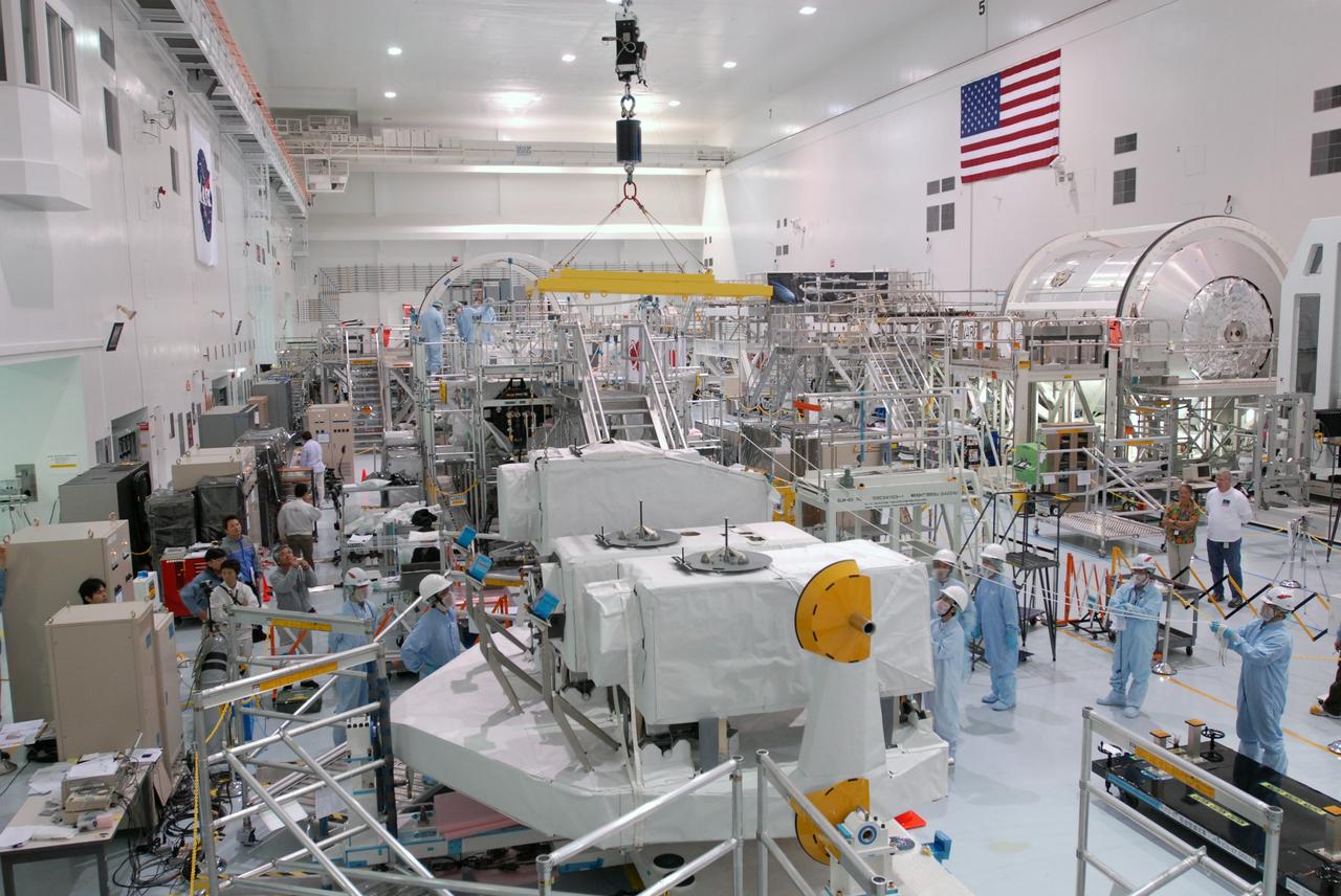
CAPE CANAVERAL, Fla. -- In the Space Station Processing Facility at NASA's Kennedy Space Center in Florida, an overhead crane lowers the ICS Exposed Facility, or ICS-EF, onto the Japanese Experiment Module's Experiment Logistics Module-Exposed Section, or ELM-ES, where it will be installed alongside two other payloads, the SEDA-AP (Space Environment Data Acquisition Equipment-Attached Payload) and MAXI (Monitor of All-sky X-ray Image). The ICS-EF is composed of several components, including an antenna, pointing mechanism, frequency converters, high-power amplifier and various sensors including the Earth sensor, Sun sensor and inertial reference unit. The ICS-EF is part of space shuttle Endeavour's payload on the STS-127 mission, targeted for launch on May 15. Photo credit: NASA/Jim Grossmann
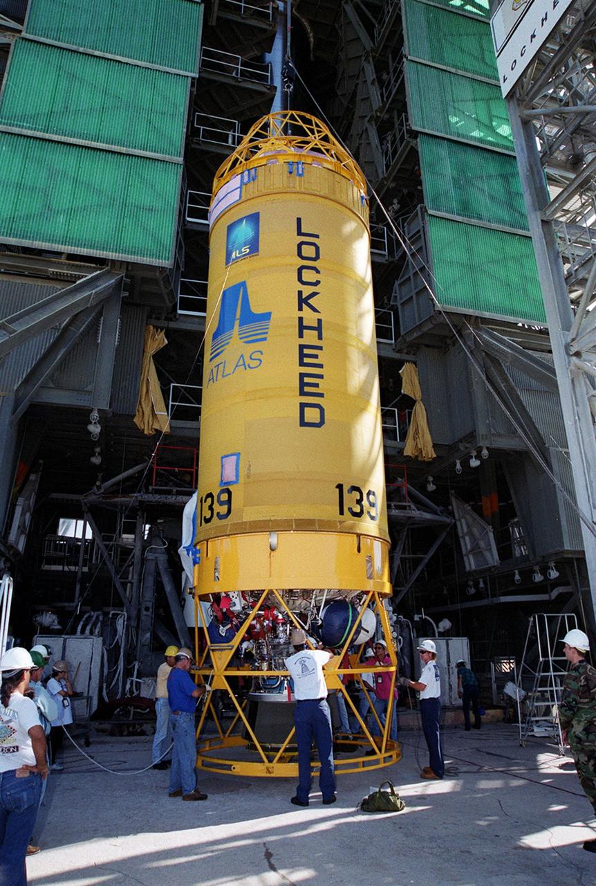
At Launch Pad 36A, Cape Canaveral Air Force Station, workers check out a Centaur rocket for its lift up the launch tower to be mated with the lower stage Atlas IIA rocket already in the tower. The Lockheed-built Atlas IIA/Centaur rocket will launch the latest Tracking and Data Relay Satellite (TDRS) June 29 from CCAFS. The TDRS is one of three (labeled H, I and J) being built in the Hughes Space and Communications Company Integrated Satellite Factory in El Segundo, Calif. The new satellites will augment the TDRS system’s existing Sand Ku-band frequencies by adding Ka-band capability. TDRS will serve as the sole means of continuous, high-data-rate communication with the space shuttle, with the International Space Station upon its completion, and with dozens of unmanned scientific satellites in low earth orbit
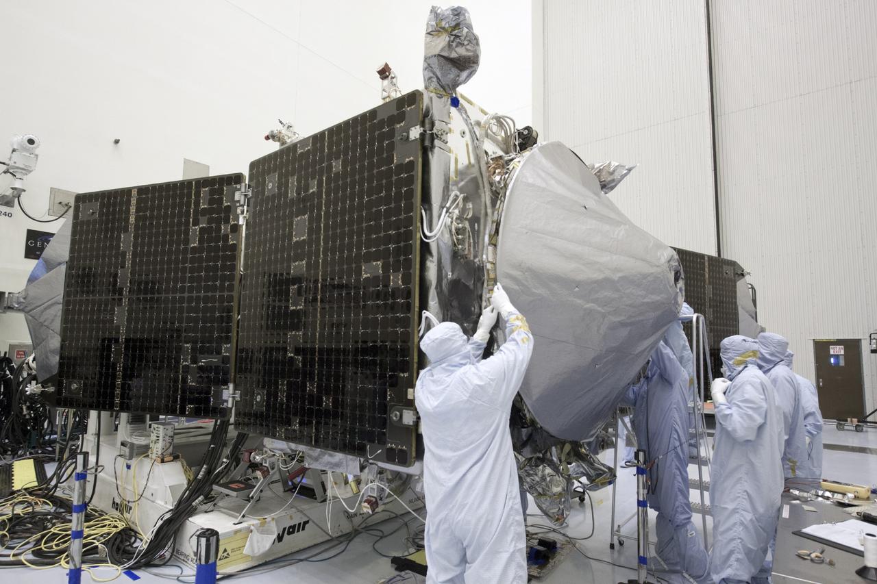
CAPE CANAVERAL, Fla. – Inside the Payload Hazardous Servicing Facility at NASA's Kennedy Space Center in Florida, engineers and technicians install a radome over the antenna for the Mars Atmosphere and Volatile Evolution, or MAVEN, spacecraft. The radome is a coated kapton cover providing thermal protection for the high gain antenna while not interfering with radio frequency transmissions from the spacecraft. MAVEN is being prepared for its scheduled launch in November from Cape Canaveral Air Force Station, Fla. atop a United Launch Alliance Atlas V rocket. Positioned in an orbit above the Red Planet, MAVEN will study the upper atmosphere of Mars in unprecedented detail. For more information, visit: http://www.nasa.gov/mission_pages/maven/main/index.html Photo credit: NASA/Jim Grossmann
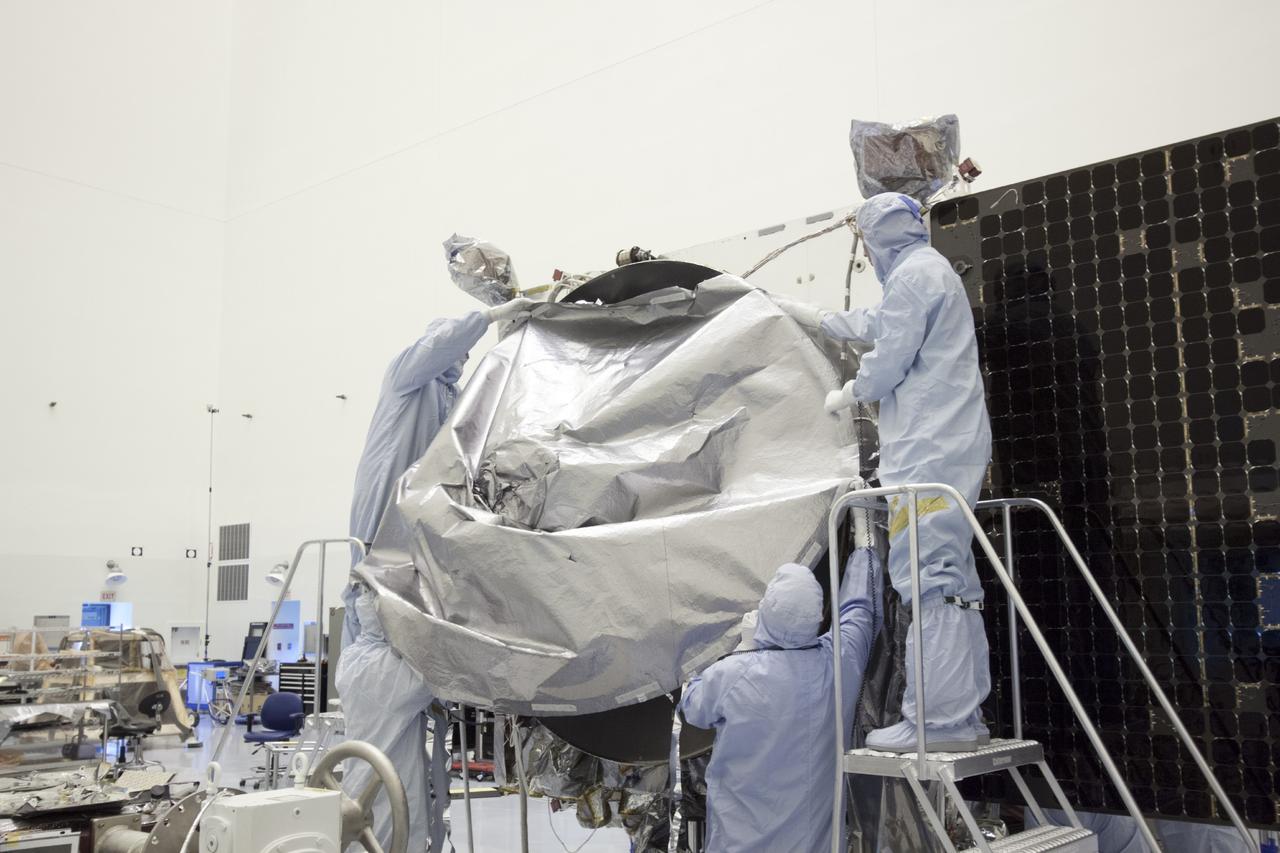
CAPE CANAVERAL, Fla. – Inside the Payload Hazardous Servicing Facility at NASA's Kennedy Space Center in Florida, engineers and technicians install a radome over the antenna for the Mars Atmosphere and Volatile Evolution, or MAVEN, spacecraft. The radome is a coated kapton cover providing thermal protection for the high gain antenna while not interfering with radio frequency transmissions from the spacecraft. MAVEN is being prepared for its scheduled launch in November from Cape Canaveral Air Force Station, Fla. atop a United Launch Alliance Atlas V rocket. Positioned in an orbit above the Red Planet, MAVEN will study the upper atmosphere of Mars in unprecedented detail. For more information, visit: http://www.nasa.gov/mission_pages/maven/main/index.html Photo credit: NASA/Jim Grossmann
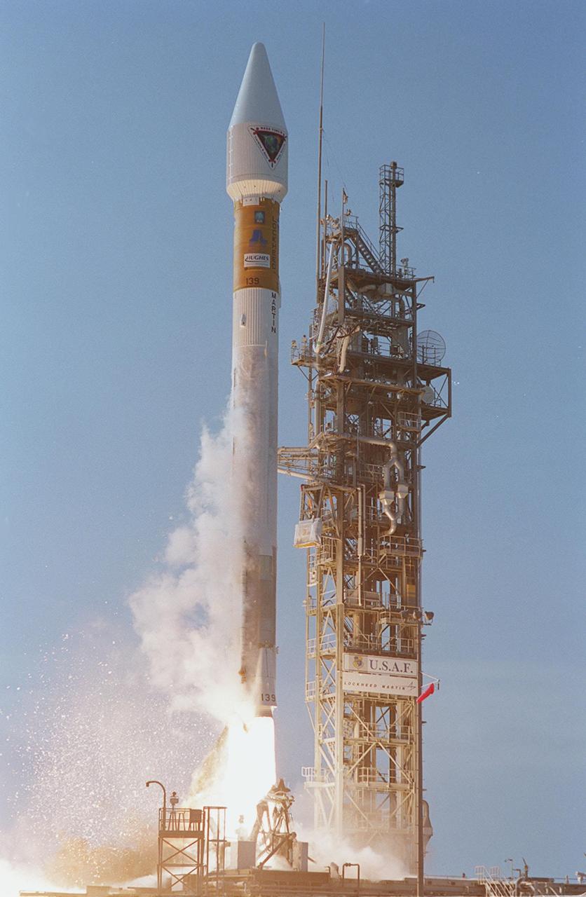
NASA’s Tracking and Data Relay Satellite (TDRS-H) rises into the blue sky from Pad 36A, Cape Canaveral Air Force Station. Liftoff occurred at 8:56 a.m. EDT aboard an Atlas IIA/Centaur rocket. One of three satellites (labeled H, I and J) being built by the Hughes Space and Communications Company, the latest TDRS uses an innovative springback antenna design. A pair of 15-foot-diameter, flexible mesh antenna reflectors fold up for launch, then spring back into their original cupped circular shape on orbit. The new satellites will augment the TDRS system’s existing Sand Ku-band frequencies by adding Ka-band capability. TDRS will serve as the sole means of continuous, high-data-rate communication with the space shuttle, with the International Space Station upon its completion, and with dozens of unmanned scientific satellites in low earth orbit

NASA’s Tracking and Data Relay Satellite (TDRS-H) sits poised on Launch Pad 36A, Cape Canaveral Air Force Station, before its scheduled launch aboard an Atlas IIA/Centaur rocket. One of three satellites (labeled H, I and J) being built by the Hughes Space and Communications Company, the latest TDRS uses an innovative springback antenna design. A pair of 15-foot-diameter, flexible mesh antenna reflectors fold up for launch, then spring back into their original cupped circular shape on orbit. The new satellites will augment the TDRS system’s existing Sand Ku-band frequencies by adding Ka-band capability. TDRS will serve as the sole means of continuous, high-data-rate communication with the space shuttle, with the International Space Station upon its completion, and with dozens of unmanned scientific satellites in low earth orbit
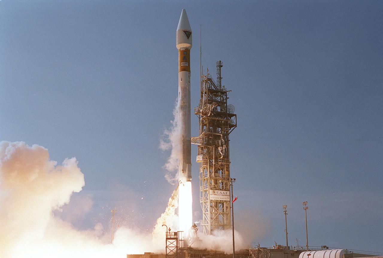
Leaving billowing clouds of steam and smoke behind, NASA’s Tracking and Data Relay Satellite (TDRS-H) shoots into the blue sky aboard an Atlas IIA/Centaur rocket from Pad 36A, Cape Canaveral Air Force Station. Liftoff occurred at 8:56 a.m. EDT. One of three satellites (labeled H, I and J) being built by the Hughes Space and Communications Company, the latest TDRS uses an innovative springback antenna design. A pair of 15-foot-diameter, flexible mesh antenna reflectors fold up for launch, then spring back into their original cupped circular shape on orbit. The new satellites will augment the TDRS system’s existing Sand Ku-band frequencies by adding Ka-band capability. TDRS will serve as the sole means of continuous, high-data-rate communication with the space shuttle, with the International Space Station upon its completion, and with dozens of unmanned scientific satellites in low earth orbit

In this long view of the launch tower at Pad 36A, Cape Canaveral Air Force Station, the upper stage Centaur rocket can be seen as it rises up the tower to be mated to the lower stage Atlas IIA rocket already there. The Lockheed-built Atlas IIA/Centaur rocket will launch the latest Tracking and Data Relay Satellite (TDRS) June 29 from CCAFS. The TDRS is one of three (labeled H, I and J) being built in the Hughes Space and Communications Company Integrated Satellite Factory in El Segundo, Calif. The new satellites will augment the TDRS system’s existing Sand Ku-band frequencies by adding Ka-band capability. TDRS will serve as the sole means of continuous, high-data-rate communication with the space shuttle, with the International Space Station upon its completion, and with dozens of unmanned scientific satellites in low earth orbit
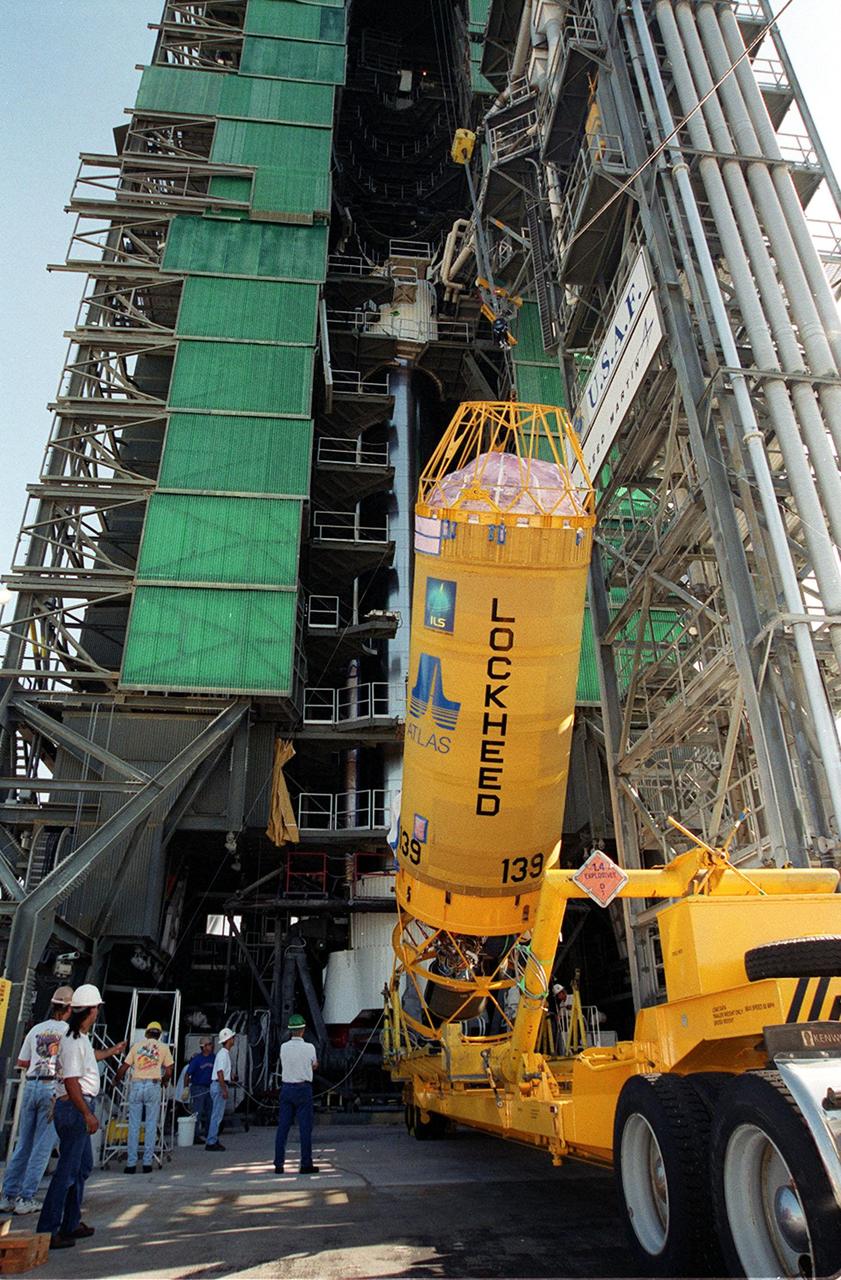
At Launch Pad 36A, Cape Canaveral Air Force Station, a Centaur rocket is raised to a vertical position before lifting it up the launch tower. It will be mated with the lower stage Atlas IIA rocket, already in the tower, to launch the latest Tracking and Data Relay Satellite (TDRS) June 29 from CCAFS. The TDRS is one of three (labeled H, I and J) being built in the Hughes Space and Communications Company Integrated Satellite Factory in El Segundo, Calif. The new satellites will augment the TDRS system’s existing Sand Ku-band frequencies by adding Ka-band capability. TDRS will serve as the sole means of continuous, high-data-rate communication with the space shuttle, with the International Space Station upon its completion, and with dozens of unmanned scientific satellites in low earth orbit

At Launch Pad 36A, Cape Canaveral Air Force Station, lines help guide the ascent of a Centaur rocket up the launch tower where it will be mated with the lower stage Atlas IIA rocket already in the tower. The Lockheed-built Atlas IIA/Centaur rocket will launch the latest Tracking and Data Relay Satellite (TDRS) June 29 from CCAFS. The TDRS is one of three (labeled H, I and J) being built in the Hughes Space and Communications Company Integrated Satellite Factory in El Segundo, Calif. The new satellites will augment the TDRS system’s existing Sand Ku-band frequencies by adding Ka-band capability. TDRS will serve as the sole means of continuous, high-data-rate communication with the space shuttle, with the International Space Station upon its completion, and with dozens of unmanned scientific satellites in low earth orbit
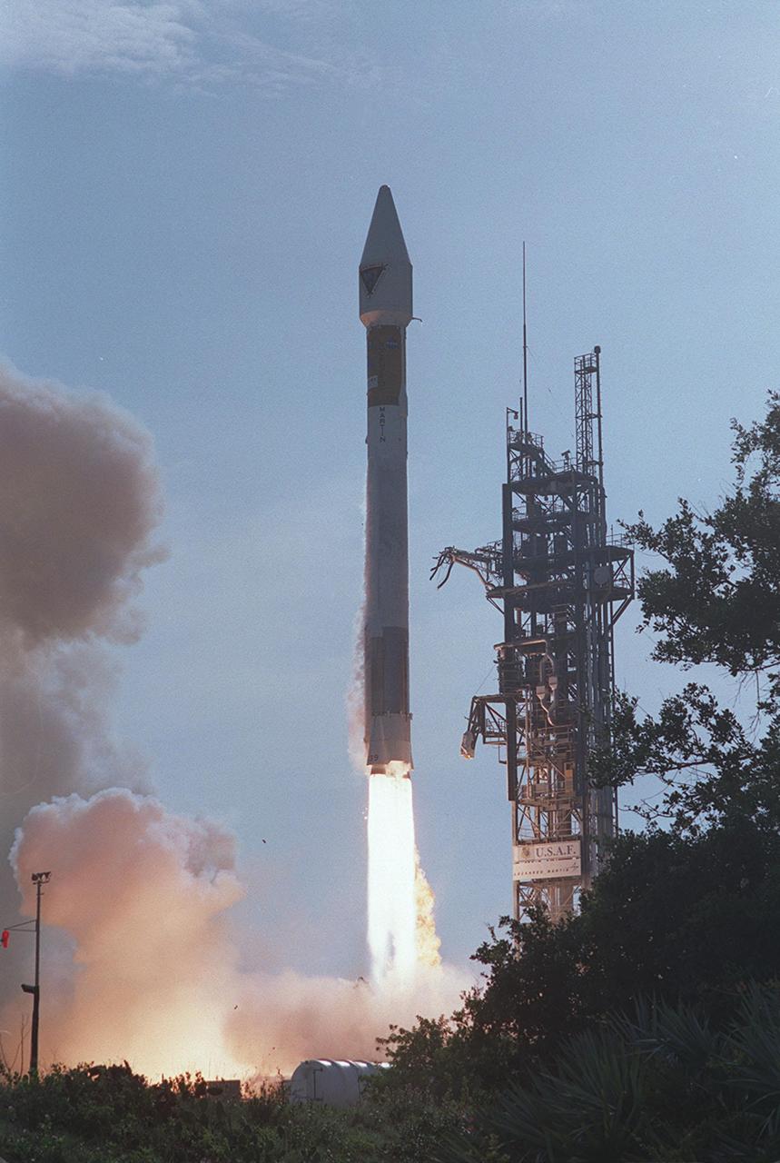
NASA’s Tracking and Data Relay Satellite (TDRS-H) rises into the blue sky from Pad 36A, Cape Canaveral Air Force Station. Liftoff occurred at 8:56 a.m. EDT aboard an Atlas IIA/Centaur rocket. One of three satellites (labeled H, I and J) being built by the Hughes Space and Communications Company, the latest TDRS uses an innovative springback antenna design. A pair of 15-foot-diameter, flexible mesh antenna reflectors fold up for launch, then spring back into their original cupped circular shape on orbit. The new satellites will augment the TDRS system’s existing Sand Ku-band frequencies by adding Ka-band capability. TDRS will serve as the sole means of continuous, high-data-rate communication with the space shuttle, with the International Space Station upon its completion, and with dozens of unmanned scientific satellites in low earth orbit
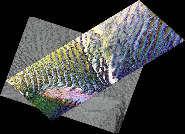
This composite image is of an area thought to contain the ruins of the ancient settlement of Niya. It is located in the southwest corner of the Taklamakan Desert in China Sinjiang Province. This region was part of some of China's earliest dynasties and from the third century BC on was traversed by the famous Silk Road. The Silk Road, passing east-west through this image, was an ancient trade route that led across Central Asia's desert to Persia, Byzantium and Rome. The multi-frequency, multi-polarized radar imagery was acquired on orbit 106 of the space shuttle Endeavour on April 16, 1994 by the Spaceborne Imaging Radar-C/X-band Synthetic Aperture Radar. The image is centered at 37.78 degrees north latitude and 82.41 degrees east longitude. The area shown is approximately 35 kilometers by 83 kilometers (22 miles by 51 miles). The image is a composite of an image from an Earth-orbiting satellite called Systeme Probatoire d'Observation de la Terre (SPOT) and a SIR-C multi-frequency, multi-polarized radar image. The false-color radar image was created by displaying the C-band (horizontally transmitted and received) return in red, the L-band (horizontally transmitted and received) return in green, and the L-band (horizontally transmitted and vertically received) return in blue. The prominent east/west pink formation at the bottom of the image is most likely a ridge of loosely consolidated sedimentary rock. The Niya River -- the black feature in the lower right of the French satellite image -- meanders north-northeast until it clears the sedimentary ridge, at which point it abruptly turns northwest. Sediment and evaporite deposits left by the river over millennia dominate the center and upper right of the radar image (in light pink). High ground, ridges and dunes are seen among the riverbed meanderings as mottled blue. Through image enhancement and analysis, a new feature probably representing a man-made canal has been discovered and mapped. http://photojournal.jpl.nasa.gov/catalog/PIA01726
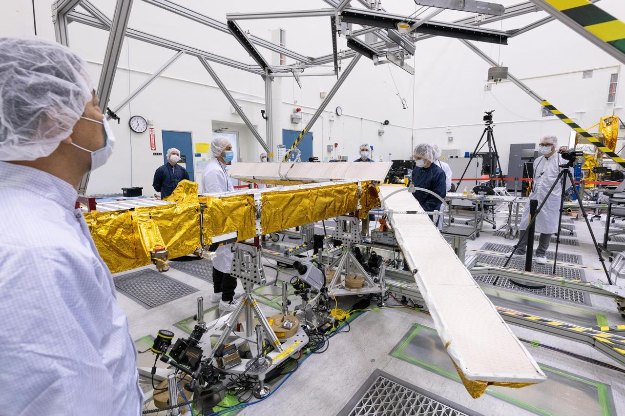
Members of the international Surface Water and Ocean Topography (SWOT) mission test one of the antennas for the Ka-band Radar Interferometer (KaRIn) instrument in a clean room at NASA's Jet Propulsion Laboratory in Southern California. The mission is a collaborative effort between NASA and the French space agency Centre National d'Études Spatiales (CNES) – with contributions from the Canadian Space Agency (CSA) and the UK Space Agency. KaRIn is the scientific heart of the SWOT satellite, which will survey the water on more than 90% of Earth's surface, measuring the height of water in lakes, rivers, reservoirs, and the ocean. To do that, KaRIn will transmit radar pulses to Earth's surface and use its two antennas to triangulate the return signals that bounce back. Mounted at the ends of a boom 33 feet (10 meters) long, the antennas will collect data along a swath 30 miles (50 kilometers) wide on either side of the satellite. KaRIn will operate in two modes: A lower-resolution mode over the ocean will involve significant onboard processing of the data to reduce the volume of information sent during downlinks to Earth; a higher-resolution mode will be used mainly over land. Scheduled to launch from Vandenberg Space Force Base in Central California on Dec. 15, 2022, SWOT is being jointly developed by NASA and CNES, with contributions from the CSA and the UK Space Agency. NASA's Jet Propulsion Laboratory, which is managed for the agency by Caltech in Pasadena, California, leads the U.S. component of the project. For the flight system payload, NASA is providing the Ka-band Radar Interferometer (KaRIn) instrument, a GPS science receiver, a laser retroreflector, a two-beam microwave radiometer, and NASA instrument operations. CNES is providing the Doppler Orbitography and Radioposition Integrated by Satellite (DORIS) system, the dual frequency Poseidon altimeter (developed by Thales Alenia Space), the KaRIn radio-frequency subsystem (together with Thales Alenia Space and with support from the UK Space Agency), the satellite platform, and ground control segment. CSA is providing the KaRIn high-power transmitter assembly. NASA is providing the launch vehicle and associated launch services. https://photojournal.jpl.nasa.gov/catalog/PIA25594
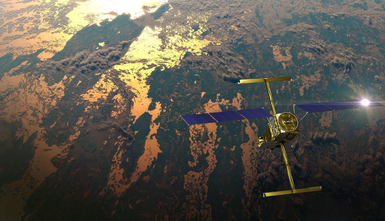
The international Surface Water and Ocean Topography (SWOT) satellite is shown in orbit over Earth in this illustration, with sunlight glinting off one of its solar arrays and both antennas of its Ka-band Radar Interferometer (KaRIn) instrument extended. The mission is a collaborative effort between NASA and the French space agency Centre National d'Études Spatiales (CNES) – with contributions from the Canadian Space Agency (CSA) and the UK Space Agency. KaRIn is the scientific heart of the SWOT satellite, which will survey the water on more than 90% of Earth's surface, measuring the height of water in lakes, rivers, reservoirs, and the ocean. To do that, KaRIn will transmit radar pulses to Earth's surface and use its two antennas to triangulate the return signals that bounce back. Mounted at the ends of a boom 33 feet (10 meters) long, the antennas will collect data along a swath 30 miles (50 kilometers) wide on either side of the satellite. KaRIn will operate in two modes: A lower-resolution mode over the ocean will involve significant onboard processing of the data to reduce the volume of information sent during downlinks to Earth; a higher-resolution mode will be used mainly over land. Scheduled to launch from Vandenberg Space Force Base in Central California on Dec. 15, 2022, SWOT is being jointly developed by NASA and CNES, with contributions from the CSA and the UK Space Agency. NASA's Jet Propulsion Laboratory, which is managed for the agency by Caltech in Pasadena, California, leads the U.S. component of the project. For the flight system payload, NASA is providing the Ka-band Radar Interferometer (KaRIn) instrument, a GPS science receiver, a laser retroreflector, a two-beam microwave radiometer, and NASA instrument operations. CNES is providing the Doppler Orbitography and Radioposition Integrated by Satellite (DORIS) system, the dual frequency Poseidon altimeter (developed by Thales Alenia Space), the KaRIn radio-frequency subsystem (together with Thales Alenia Space and with support from the UK Space Agency), the satellite platform, and ground control segment. CSA is providing the KaRIn high-power transmitter assembly. NASA is providing the launch vehicle and associated launch services. https://photojournal.jpl.nasa.gov/catalog/PIA25595
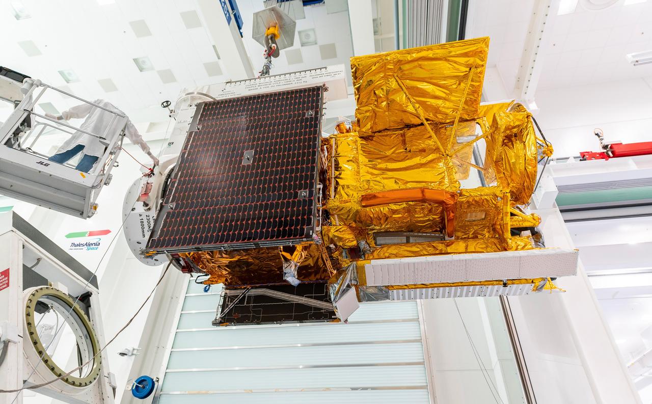
Workers in a clean room in Cannes, France, load the Surface Water and Ocean Topography (SWOT) satellite into a container in preparation for shipping the spacecraft to the U.S. SWOT is an international mission led by NASA and the French space agency Centre National d'Études Spatiales (CNES) that will survey water on more than 90% of Earth's surface. The spacecraft will view water in Earth's lakes, rivers, reservoirs, and the ocean in higher definition than ever before. The information that SWOT gathers will help inform water management decisions and prepare communities for rising seas and changing coastlines. It will also help researchers better understand the exchange of heat and carbon between the ocean and atmosphere, an important component of the role that Earth's ocean plays in the planet's climate. SWOT will launch out of the Vandenberg Space Force Base in central California no earlier than Dec. 5, 2022. SWOT is being jointly developed by NASA and CNES, with contributions from the Canadian Space Agency and the United Kingdom Space Agency. JPL, which is managed for NASA by Caltech in Pasadena, California, leads the U.S. component of the project. For the flight system payload, NASA is providing the KaRIn instrument, a GPS science receiver, a laser retroreflector, a two-beam microwave radiometer, and NASA instrument operations. CNES is providing the Doppler Orbitography and Radioposition Integrated by Satellite (DORIS) system, the dual frequency Poseidon altimeter (developed by Thales Alenia Space), the KaRIn radio-frequency subsystem (together with Thales Alenia Space and with support from the UK Space Agency), the platform, and ground control segment. CSA is providing the KaRIn high-power transmitter assembly. NASA is providing the launch vehicle and associated launch services. https://photojournal.jpl.nasa.gov/catalog/PIA24910