
HYPERVELOCITY BALLISTICS RANGE (HBR) IMPACT CHAMBER, HI SPEED FARAMING CAMERA & STATIONS
HFF (Hypervelocity Free-Flight) N-237 Impact Studies (For JSC)
HFF (Hypervelocity Free-Flight) N-237 Impact Studies (For JSC)
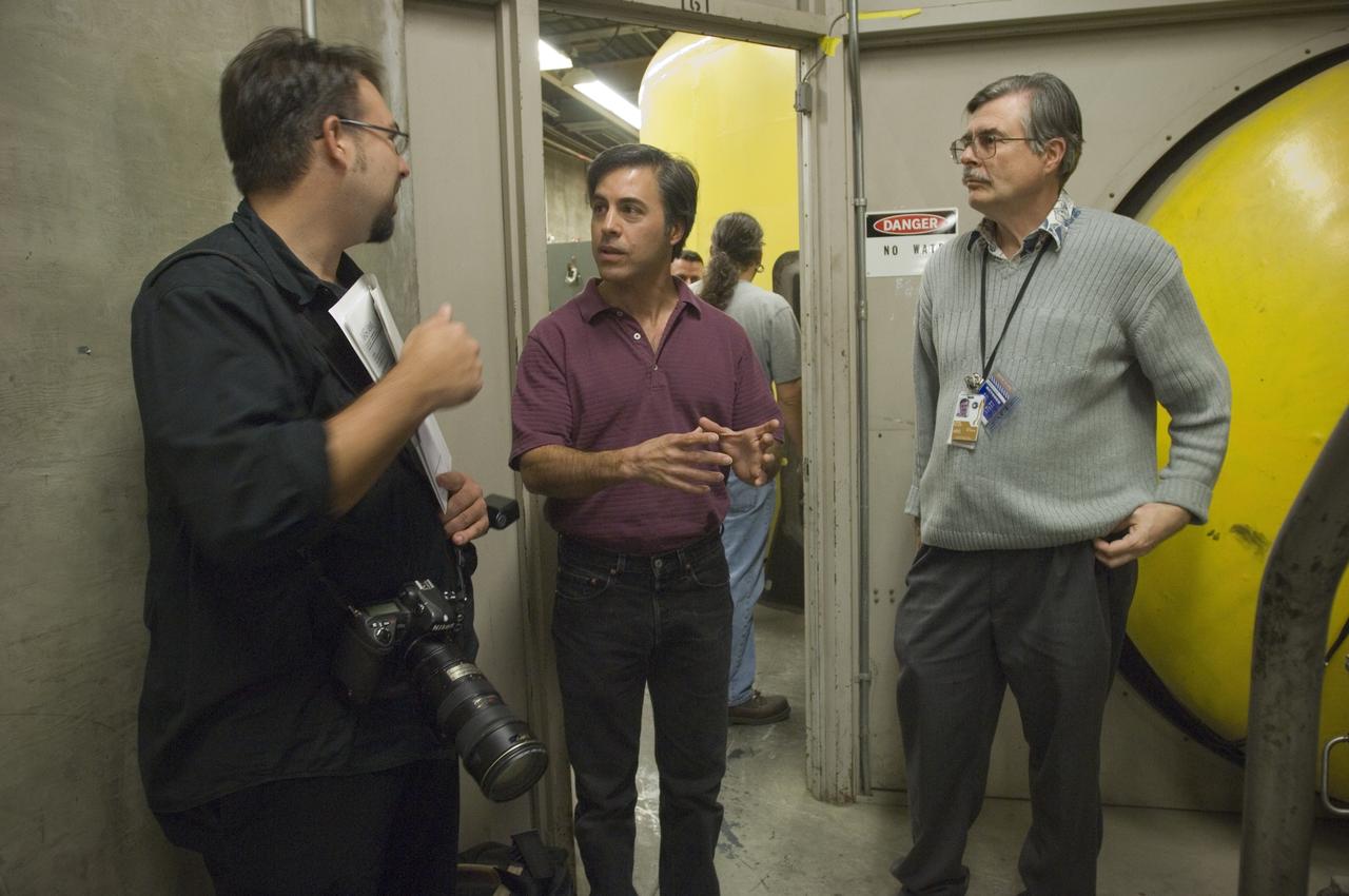
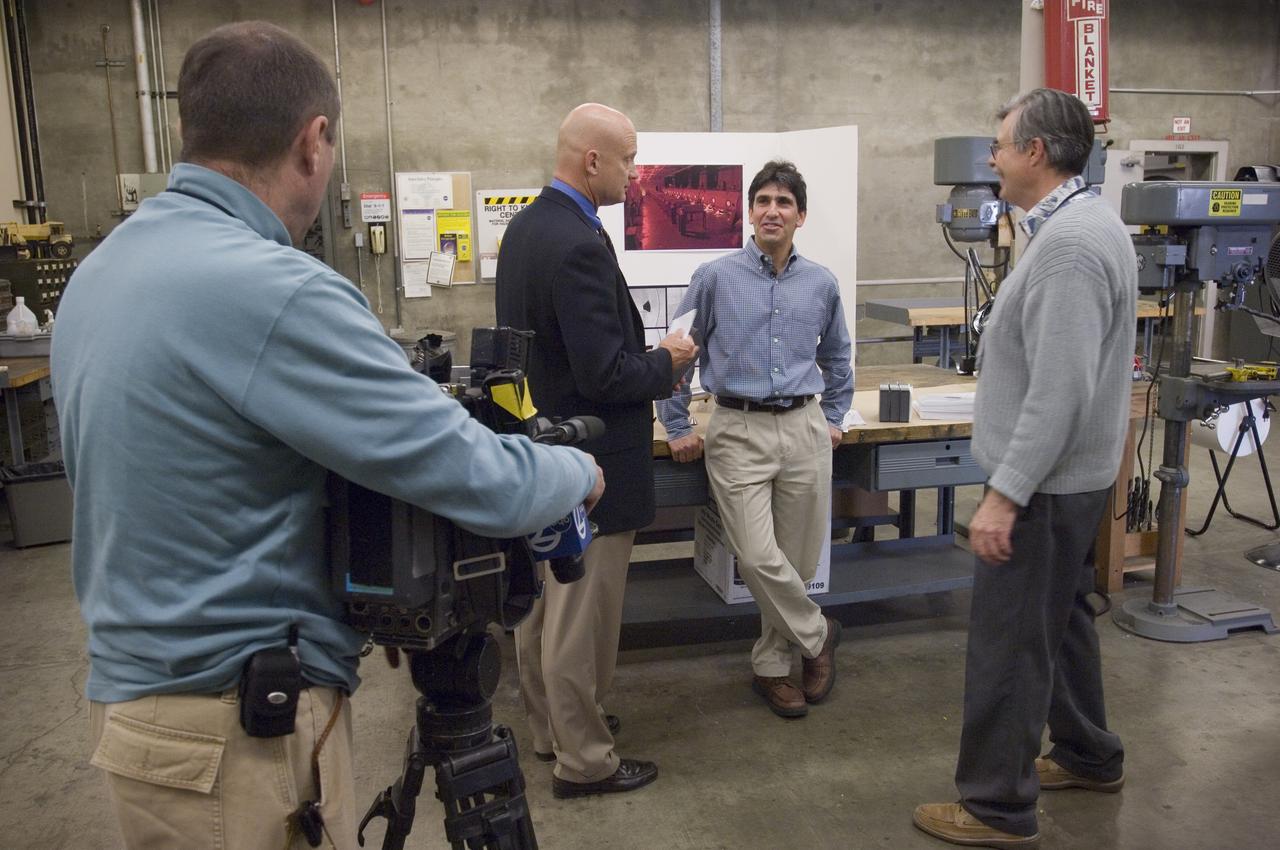
Ames holds a Media Day at the Hypervelocity Free Flight facility where Ames is conducting high-speed tests of small models of the agency's new Orion CEV to learn about stability during flight. The hypervelocity test facility uses a gun to shoot Orion models between 0.5 and l.5 inches (1.25 - 3.75 centimeters in diameter. The facility can conduct experiments with speeds up to 19,000 miles per hour (30,400 kilometers per hour) with John Bluck (Ames PAO) and Chuck Cornelison Ames Engineer

.50 Cal Gun Range: Hypervelocity Impact Test; 6.8 km/s
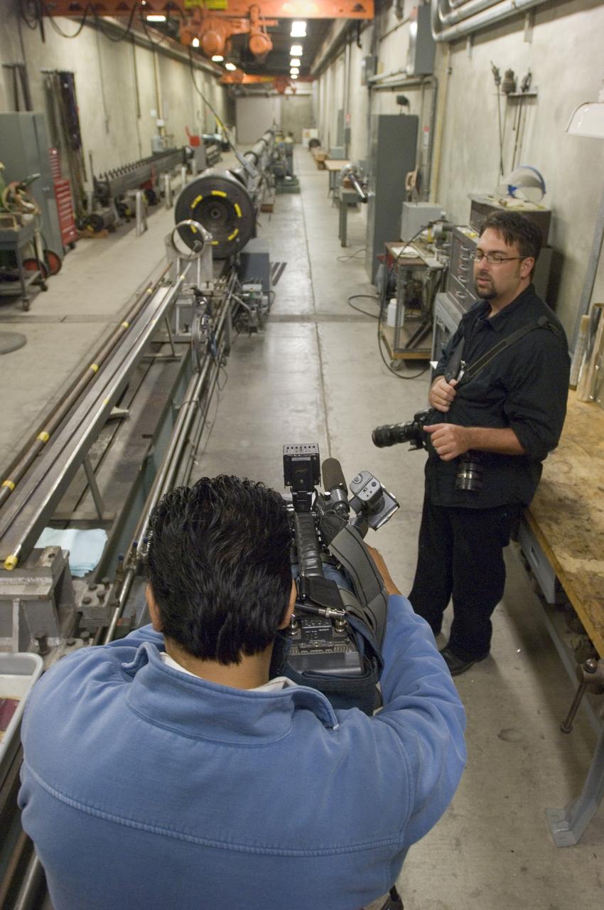
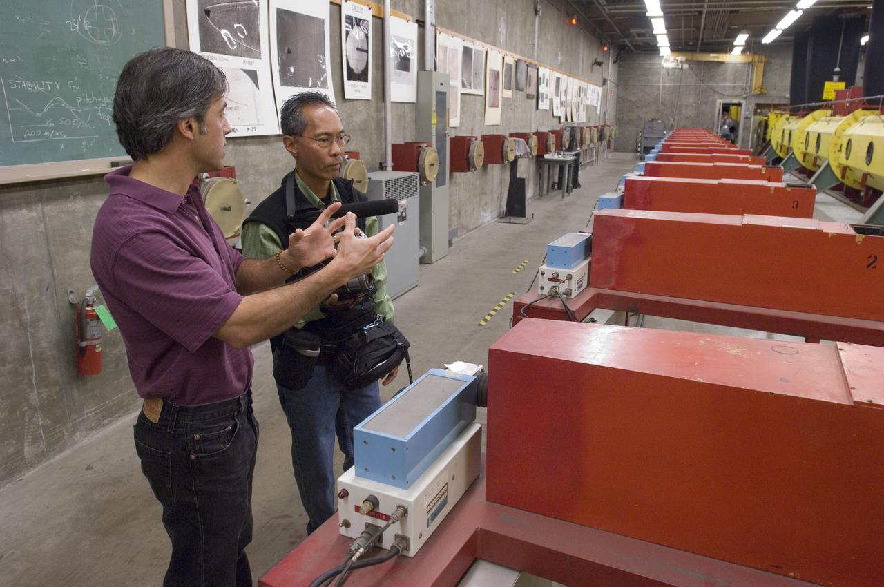
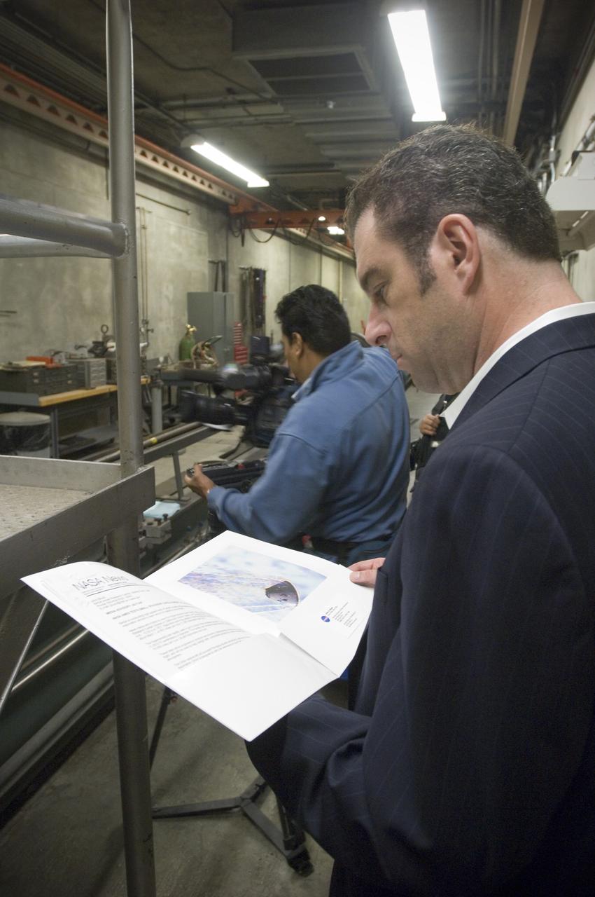
Ames holds a Media Day at the Hypervelocity Free Flight facility where Ames is conducting high-speed tests of small models of the agency's new Orion CEV to learn about stability during flight. The hypervelocity test facility uses a gun to shoot Orion models between 0.5 and l.5 inches (1.25 - 3.75 centimeters in diameter. The facility can conduct experiments with speeds up to 19,000 miles per hour (30,400 kilometers per hour) - Cesar Acosta, NASA photographer in forground and a news camera men taking shot of the gun facility
Ames holds a Media Day at the Hypervelocity Free Flight facility where Ames is conducting high-speed tests of small models of the agency's new Orion CEV to learn about stability during flight. The hypervelocity test facility uses a gun to shoot Orion models between 0.5 and l.5 inches (1.25 - 3.75 centimeters in diameter. The facility can conduct experiments with speeds up to 19,000 miles per hour (30,400 kilometers per hour) - ABC Camerman in forground, Wayne Freedman ABC reporter, Jeff Brown (Ames-ASA), John Bluck (AMES PAO)
Ames holds a Media Day at the Hypervelocity Free Flight facility where Ames is conducting high-speed tests of small models of the agency's new Orion CEV to learn about stability during flight. The hypervelocity test facility uses a gun to shoot Orion models between 0.5 and l.5 inches (1.25 - 3.75 centimeters in diameter. The facility can conduct experiments with speeds up to 19,000 miles per hour (30,400 kilometers per hour) - Gary Reyes, San Jose mercury New interviews Chuck Cornelison
Ames holds a Media Day at the Hypervelocity Free Flight facility where Ames is conducting high-speed tests of small models of the agency's new Orion CEV to learn about stability during flight. The hypervelocity test facility uses a gun to shoot Orion models between 0.5 and l.5 inches (1.25 - 3.75 centimeters in diameter. The facility can conduct experiments with speeds up to 19,000 miles per hour (30,400 kilometers per hour) - NBC Channel 11 Technology/Business reporter Scott Budman at the gun range (w/C Acosta in bkgrd)

Ames holds a Media Day at the Hypervelocity Free Flight facility where Ames is conducting high-speed tests of small models of the agency's new Orion CEV to learn about stability during flight. The hypervelocity test facility uses a gun to shoot Orion models between 0.5 and l.5 inches (1.25 - 3.75 centimeters in diameter. The facility can conduct experiments with speeds up to 19,000 miles per hour (30,400 kilometers per hour) - Wayne Freedman, ABC Channel 7 news inerviews Jeff Brown of Ames
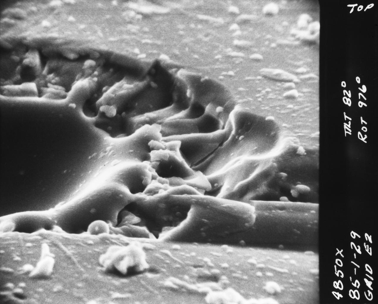
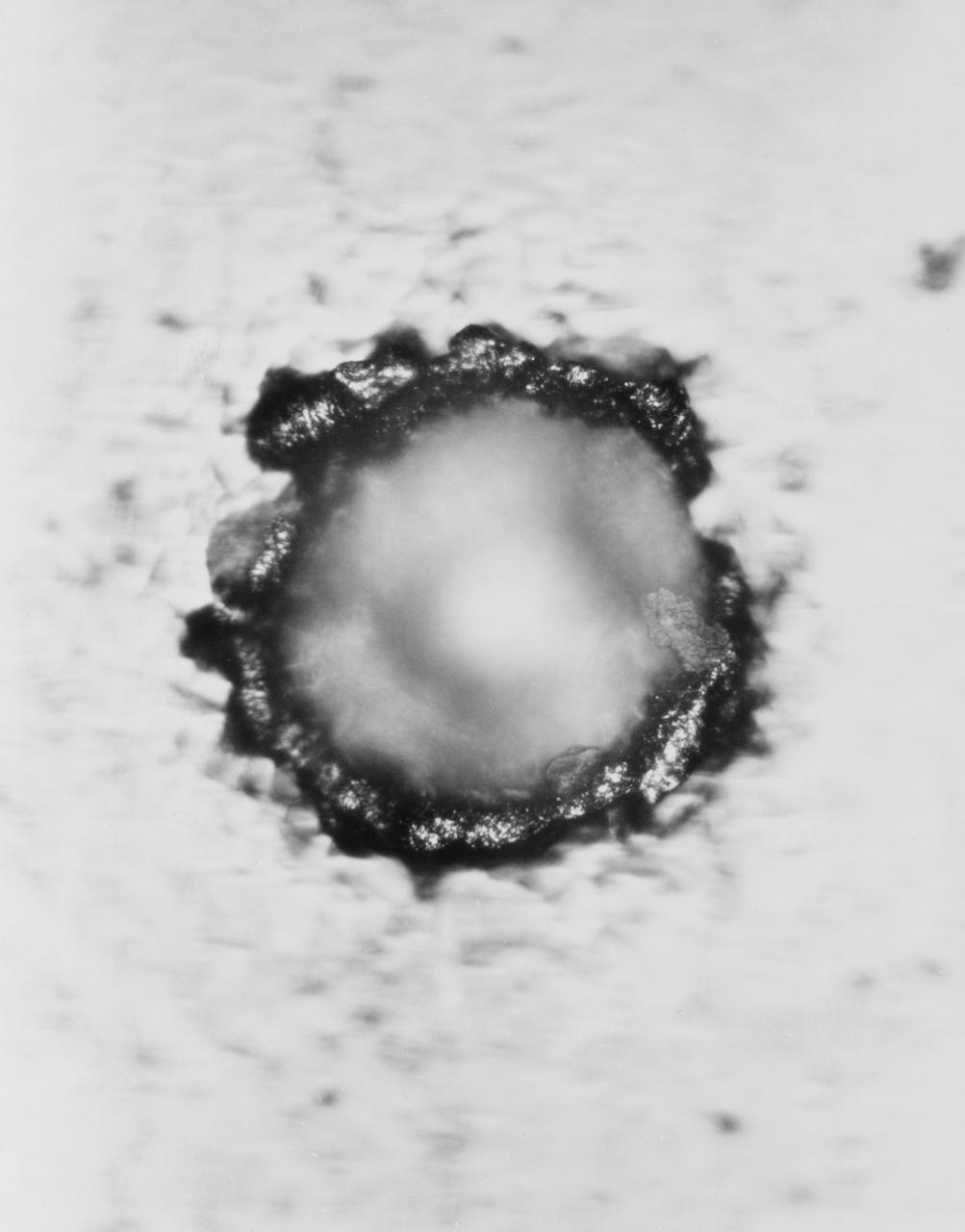
S70-20417 (December 1969) --- Enlarged view shows hypervelocity impact of cosmic dust on broken glass particles, taken during the examination of Apollo 11 lunar material by Dr. G. J. Wasserberg, J. DeVaney and K. Evans at California Institute of Technology. The photograph is enlarged 4,850 times actual size.
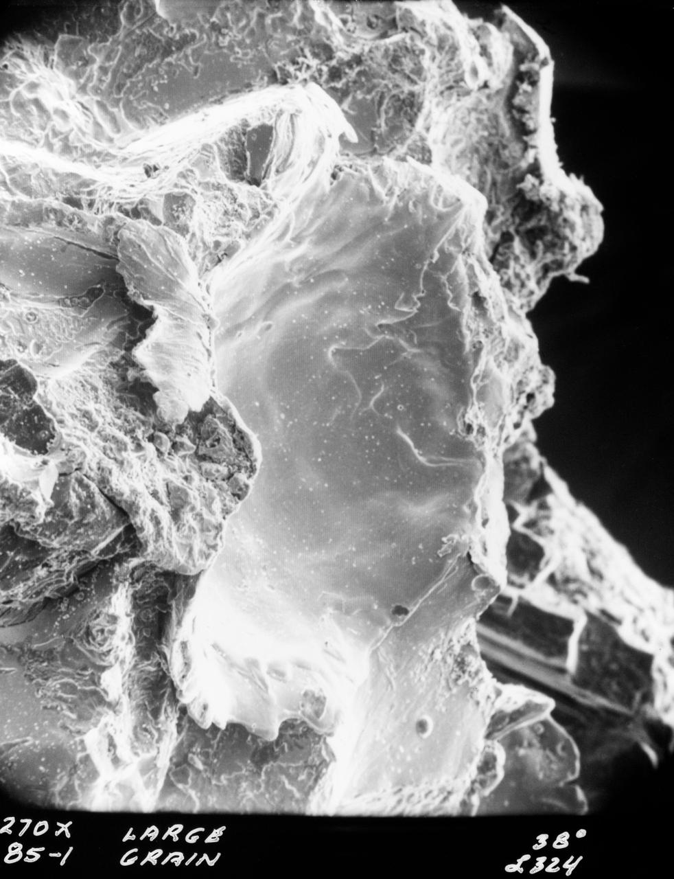
S70-20416 (December 1969) --- Enlarged view show hypervelocity impact on iron particles of lunar surface material returned to Earth by the crew of the Apollo 11 lunar landing mission. This photograph, enlarged to 270 times the actual size, was taken by Dr. G. J. Wasserberg, J. DeVaney and K. Evans at the California Institute of Technology.
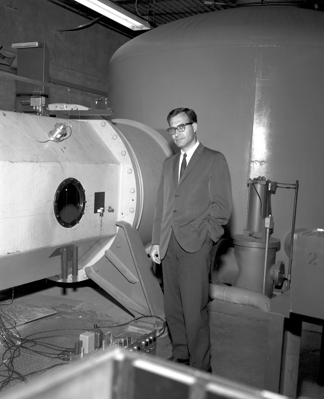
Alvin Seiff at Hypervelocity Free Flight Facility at the Ames Research Center.
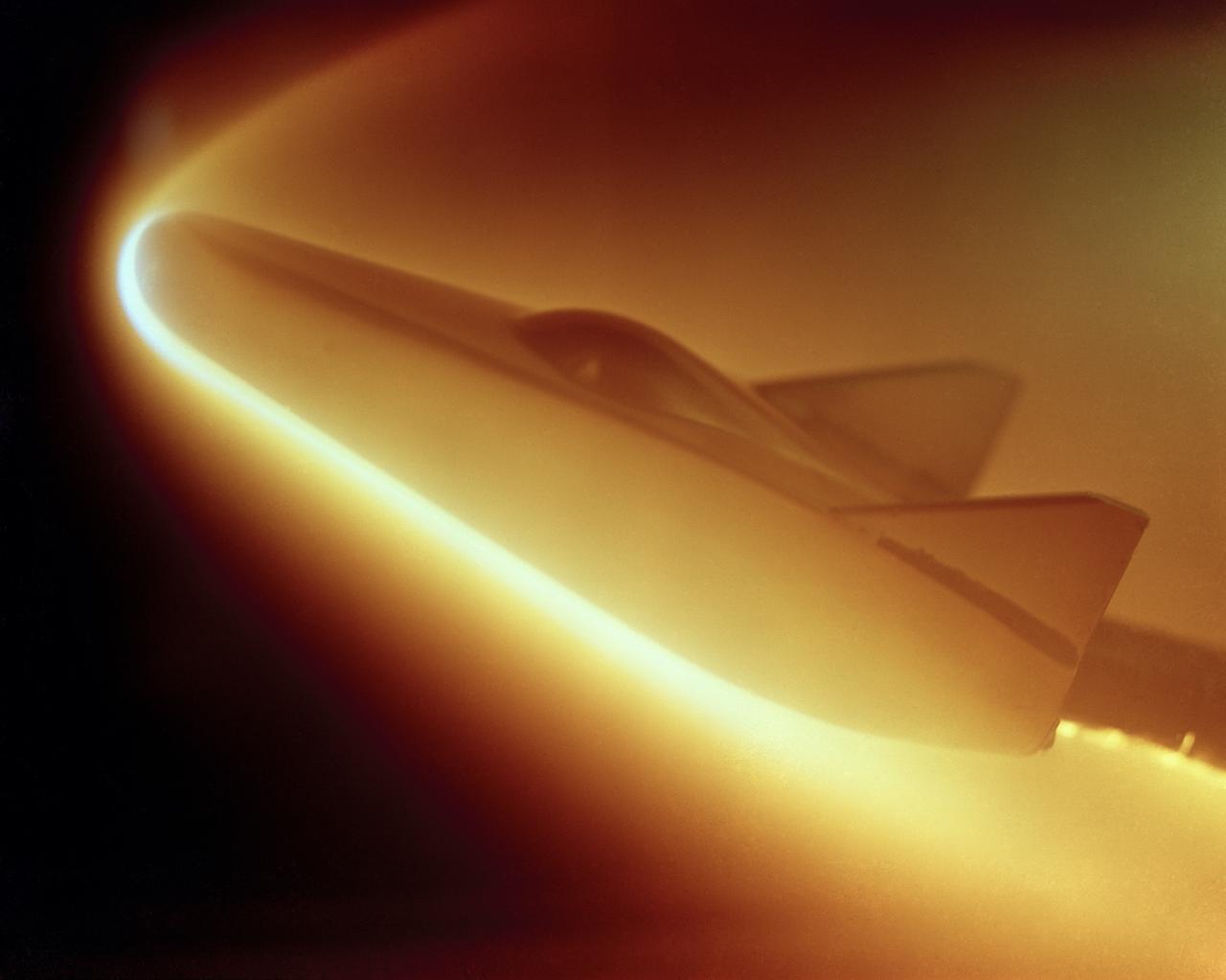
M-2 lifting body; heat transfer distribution test in the 1 ft hypervelocity wind tunnel
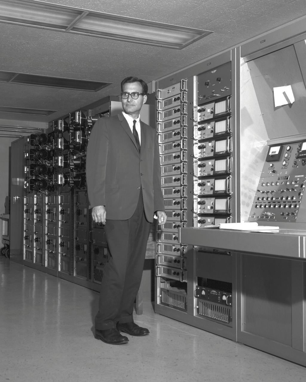
Alvin Seiff at Hypervelocity Free Flight Facility control room at the Ames Research Center.
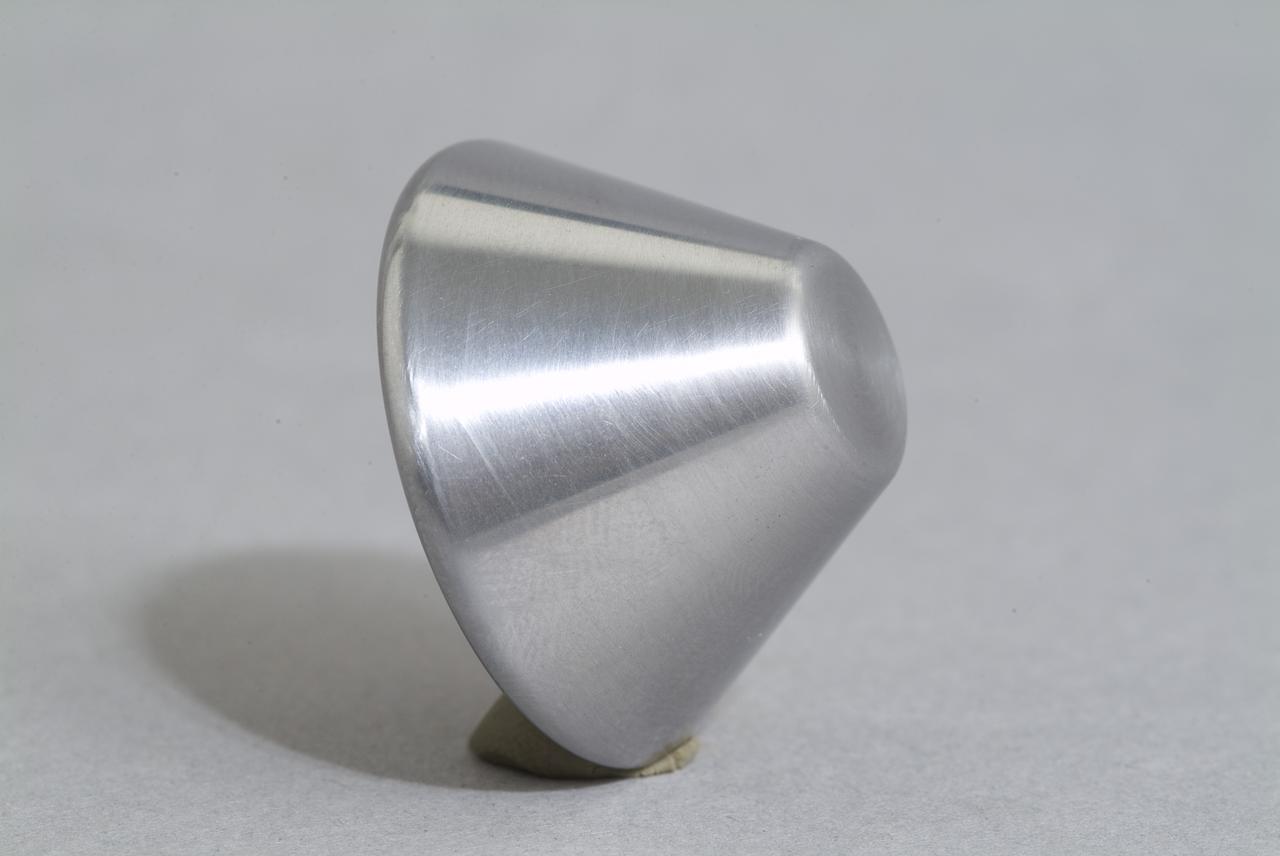
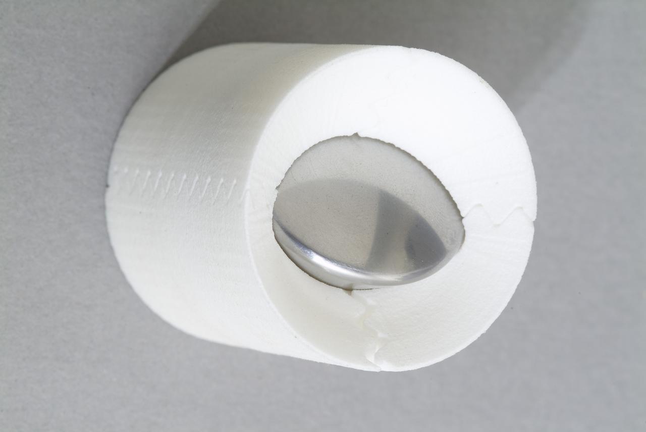
CEV (Crew Escape Vehicle) capsule Balistic Range testing to examine static and dynamic stability characteristics (at the Hypervelocity Free-Flight Facility) HFF
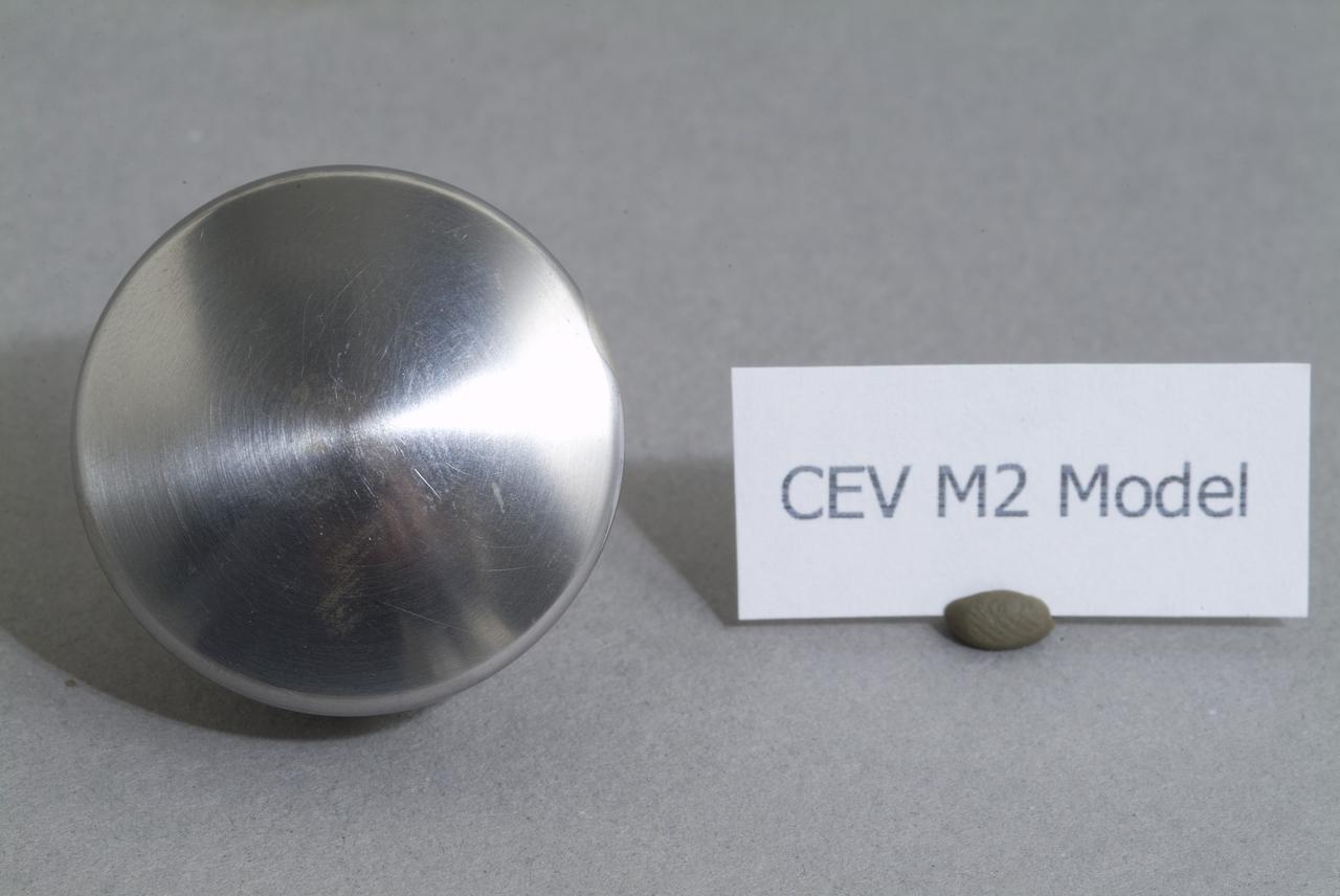
CEV (Crew Escape Vehicle) capsule Balistic Range testing to examine static and dynamic stability characteristics (at the Hypervelocity Free-Flight Facility) HFF
CEV (Crew Escape Vehicle) capsule Balistic Range testing to examine static and dynamic stability characteristics (at the Hypervelocity Free-Flight Facility) HFF
CEV (Crew Escape Vehicle) capsule Balistic Range testing to examine static and dynamic stability characteristics (at the Hypervelocity Free-Flight Facility) HFF
CEV (Crew Escape Vehicle) capsule Balistic Range testing to examine static and dynamic stability characteristics (at the Hypervelocity Free-Flight Facility) HFF
CEV (Crew Escape Vehicle) capsule Balistic Range testing to examine static and dynamic stability characteristics (at the Hypervelocity Free-Flight Facility) HFF
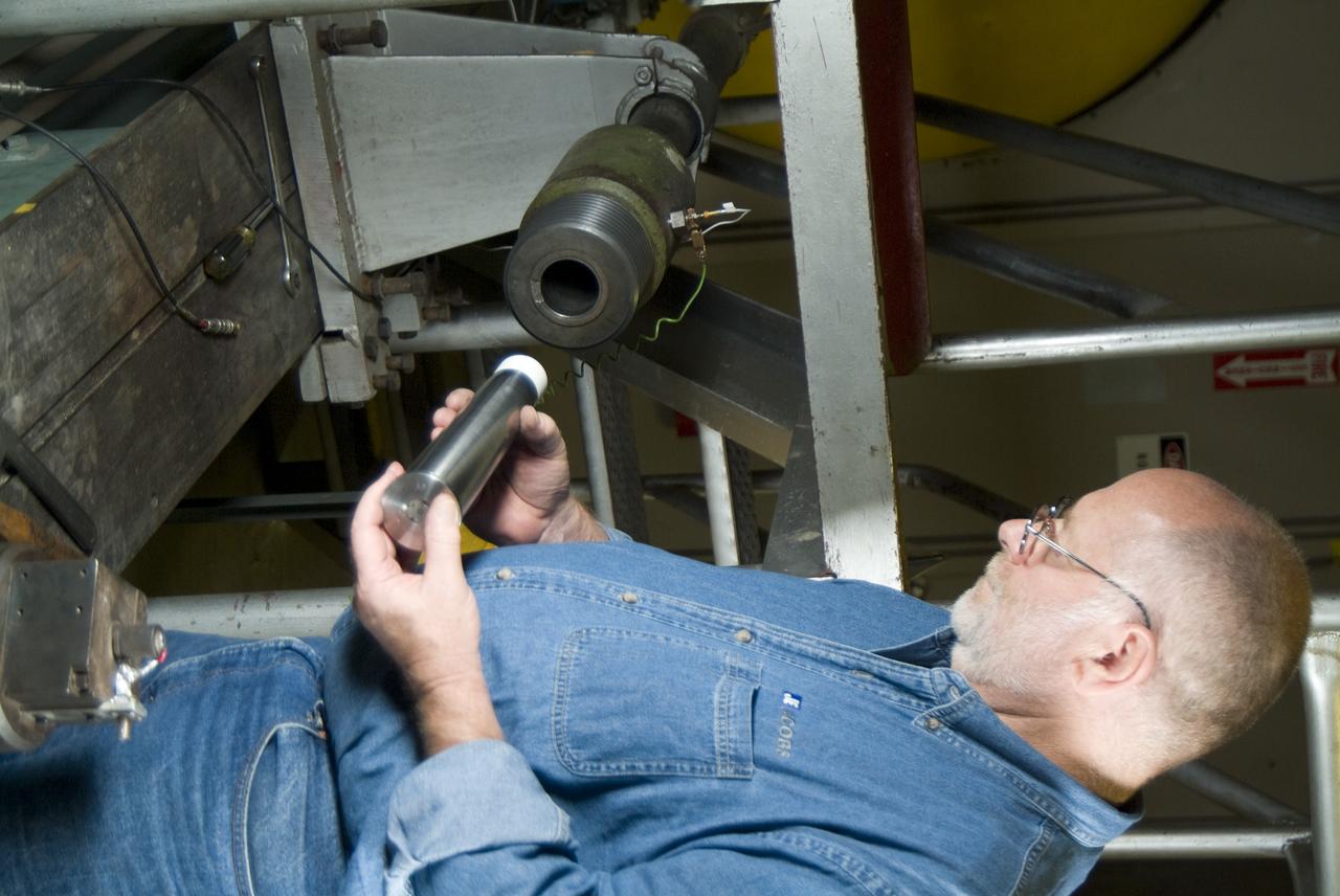
CEV (Crew Escape Vehicle) capsule Balistic Range testing to examine static and dynamic stability characteristics (at the Hypervelocity Free-Flight Facility) HFF - Don Holt installing projectile & powder charge
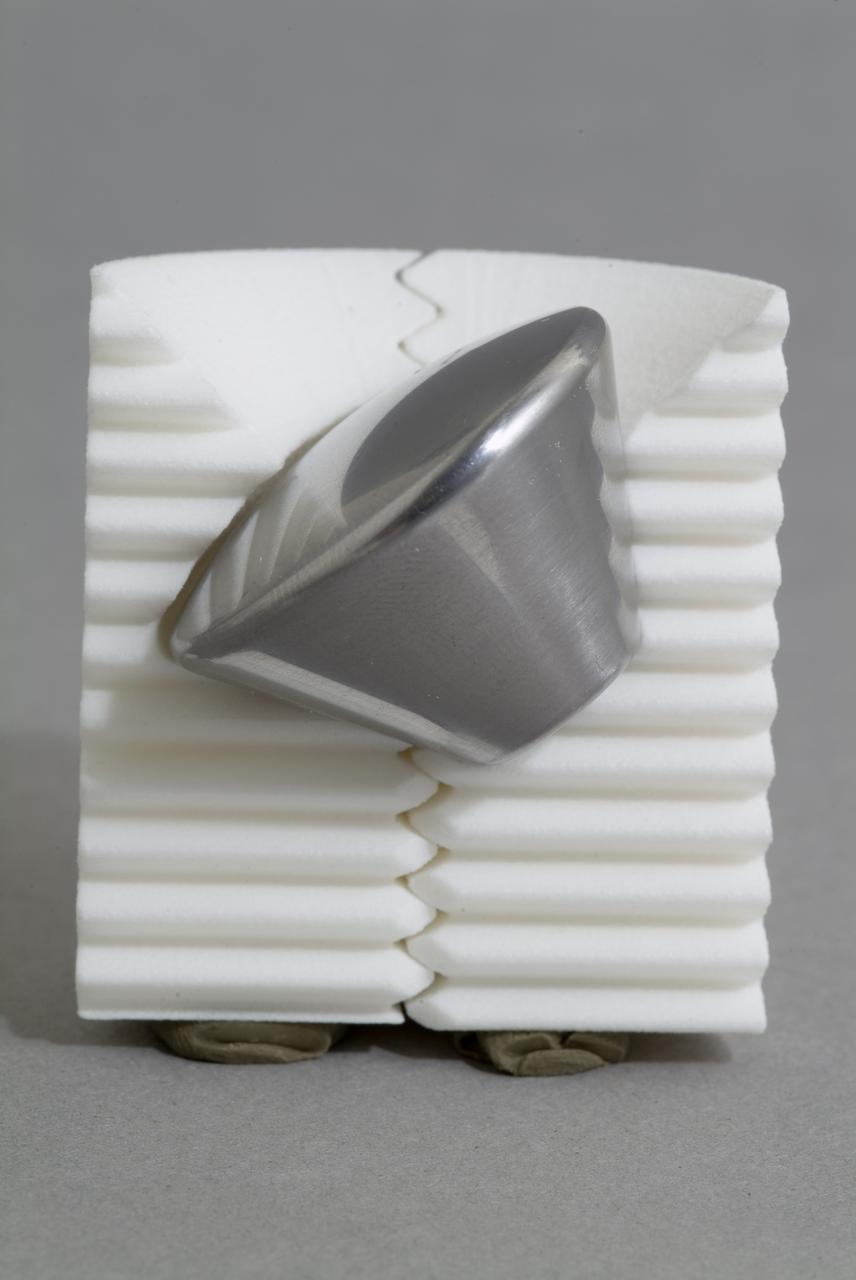
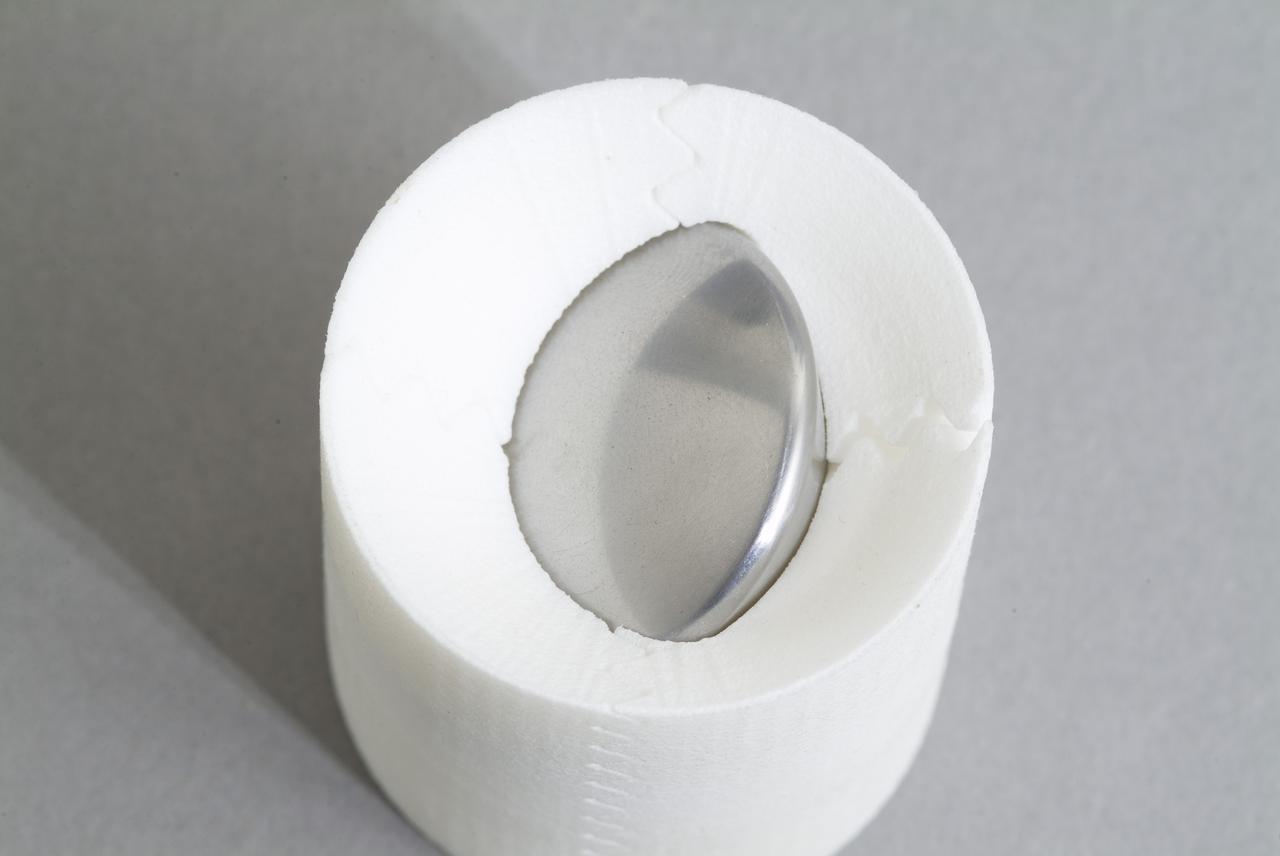
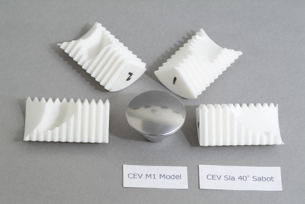
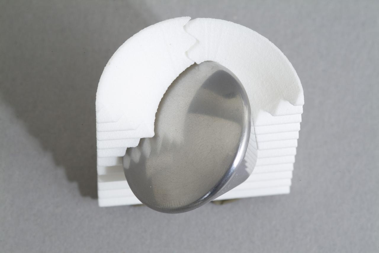
CEV (Crew Escape Vehicle) capsule Balistic Range testing to examine static and dynamic stability characteristics (at the Hypervelocity Free-Flight Facility) HFF - model M-1 in 40 degree initial launch angle with sabot
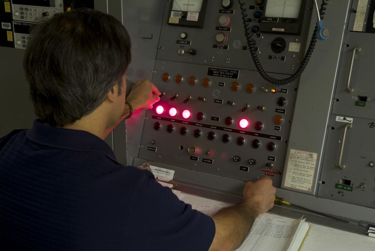
CEV (Crew Escape Vehicle) capsule Balistic Range testing to examine static and dynamic stability characteristics (at the Hypervelocity Free-Flight Facility) HFF Chuck Cornelison operating 'Firing' control pannel

CEV (Crew Escape Vehicle) capsule Balistic Range testing to examine static and dynamic stability characteristics (at the Hypervelocity Free-Flight Facility) HFF - Bon Bowling machining sabot to find dimensions
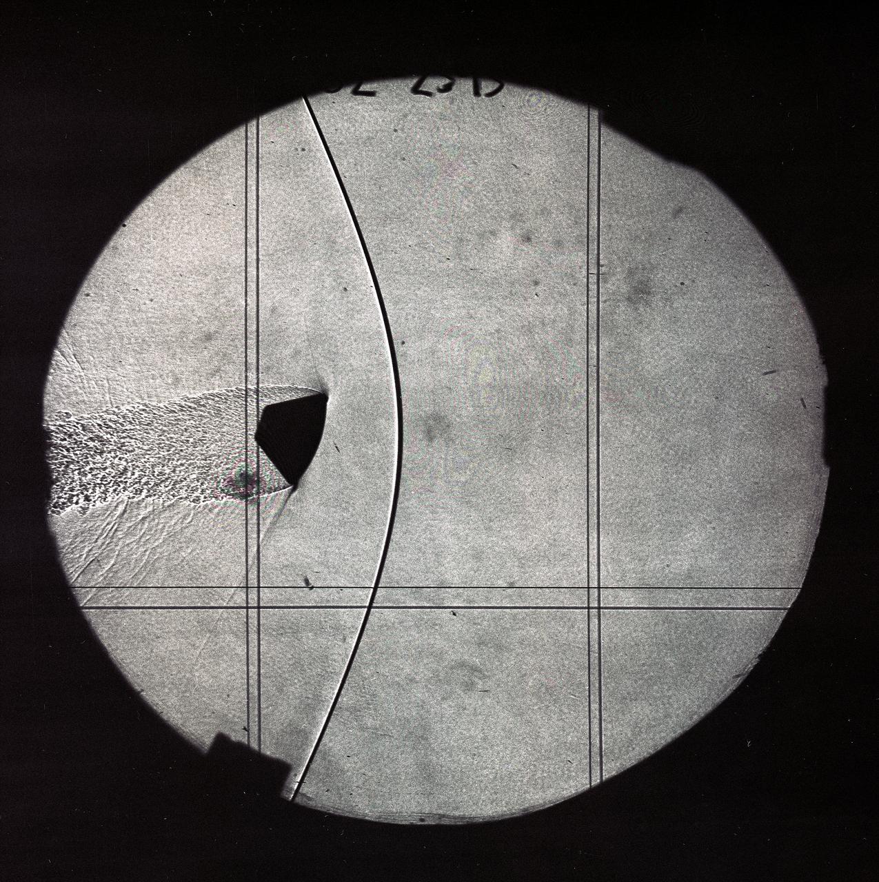
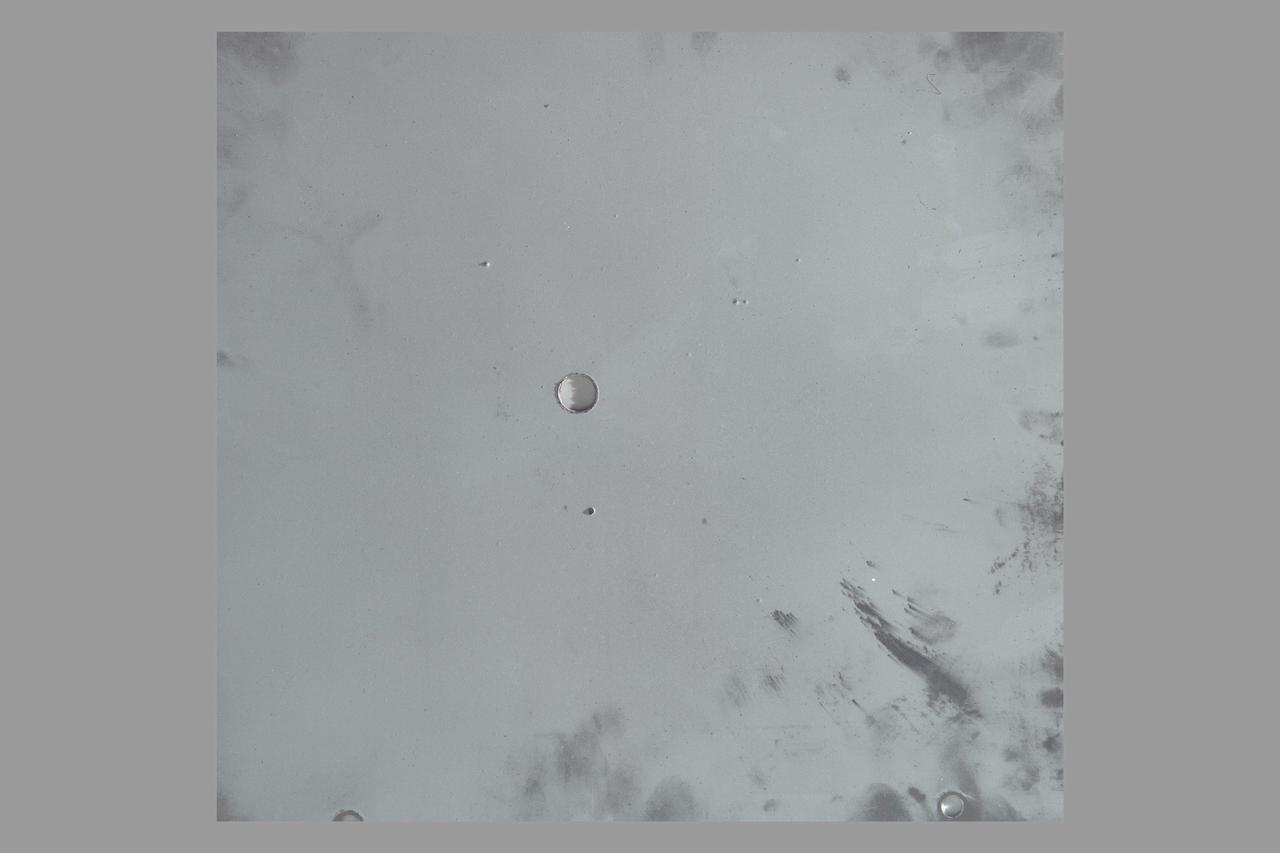
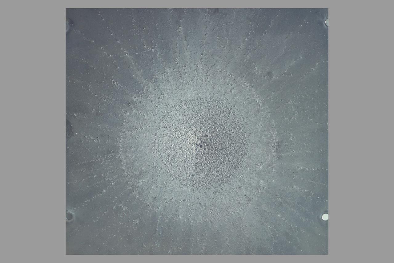
CEV (Crew Escape Vehicle) capsule Balistic Range testing to examine static and dynamic stability characteristics (at the Hypervelocity Free-Flight Facility) HFF - scans of shadowgraphs from 8x10 film images
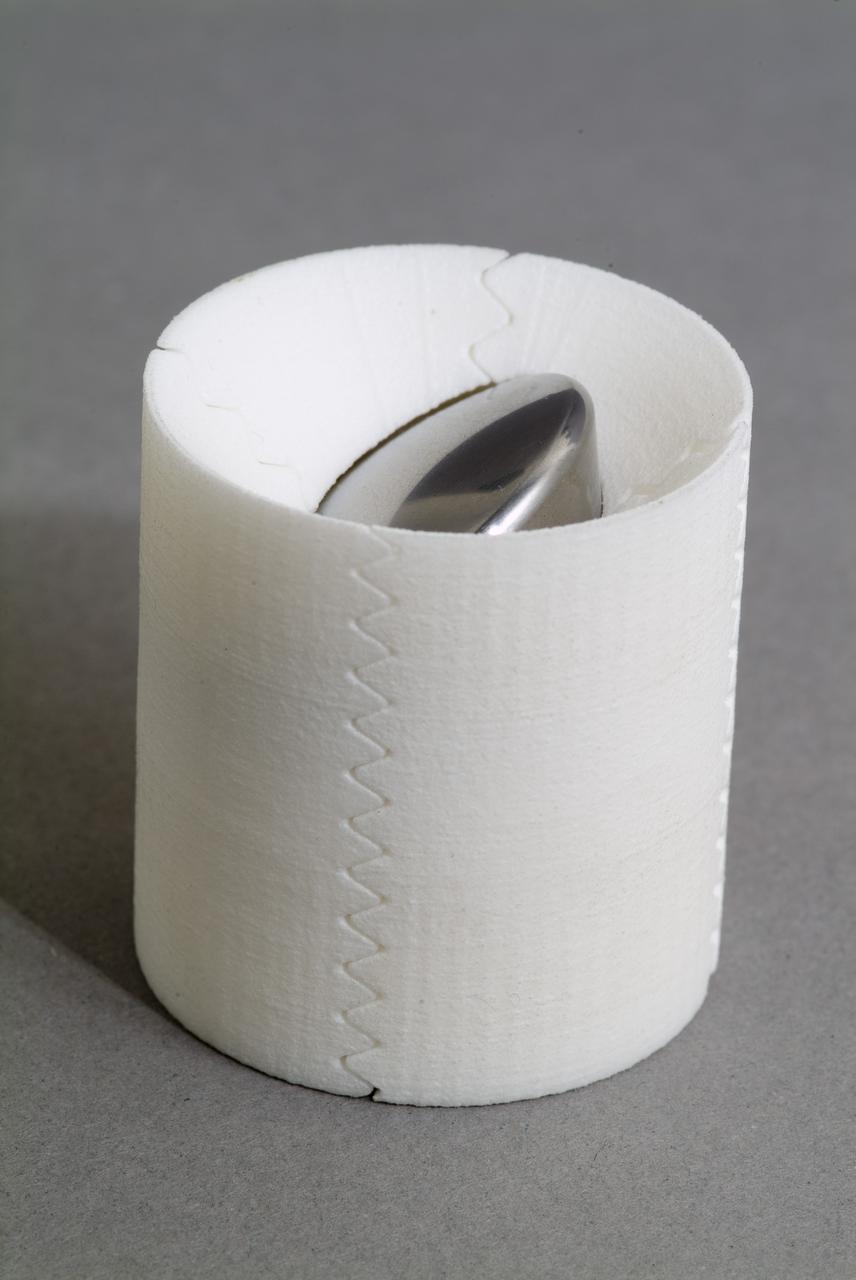
CEV (Crew Escape Vehicle) capsule Balistic Range testing to examine static and dynamic stability characteristics (at the Hypervelocity Free-Flight Facility) HFF - model M-1 in 40 degree initial launch angle with sabot
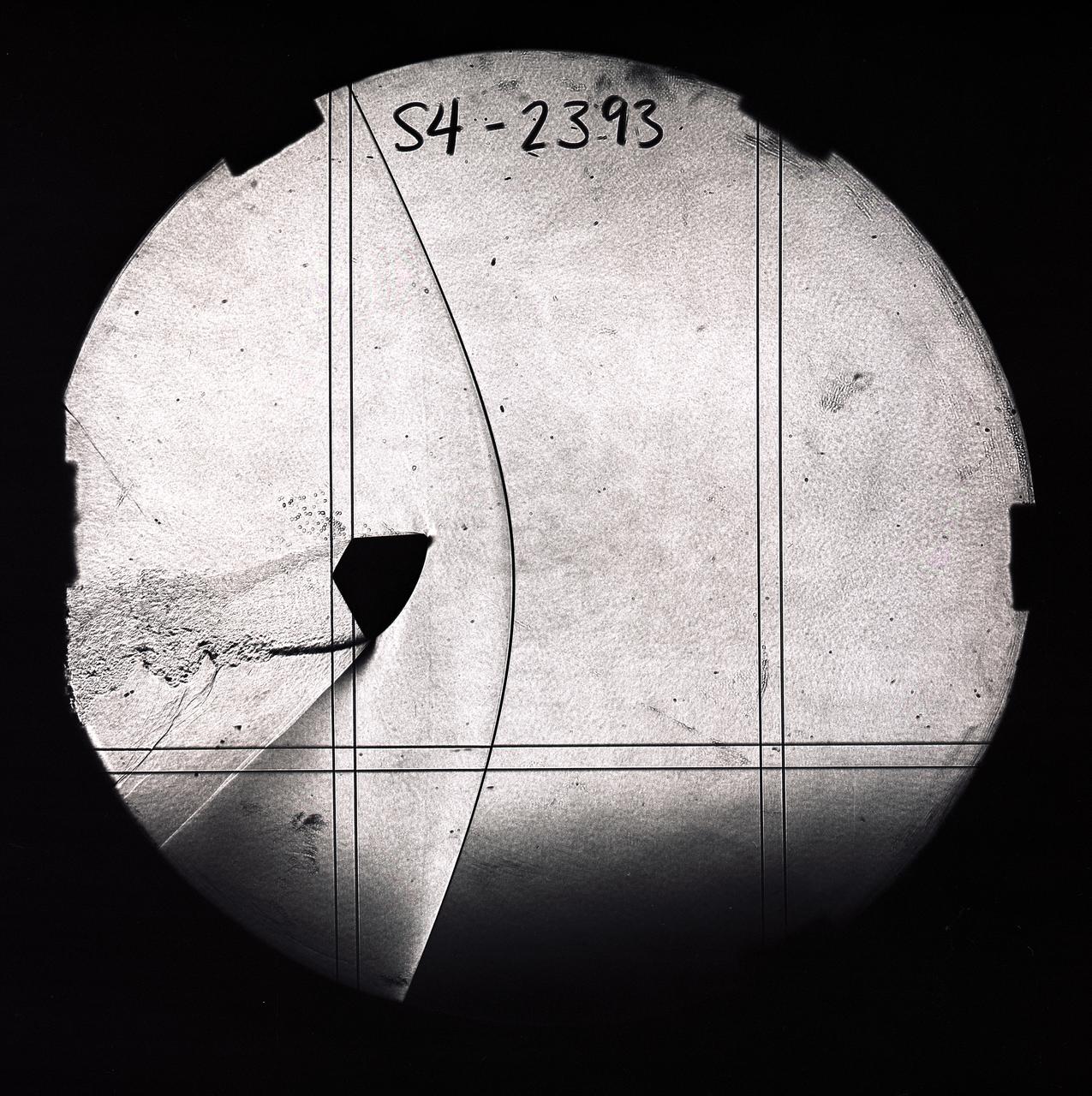
CEV (Crew Escape Vehicle) capsule Balistic Range testing to examine static and dynamic stability characteristics (at the Hypervelocity Free-Flight Facility) HFF - scans of shadowgraphs from 8x10 film images
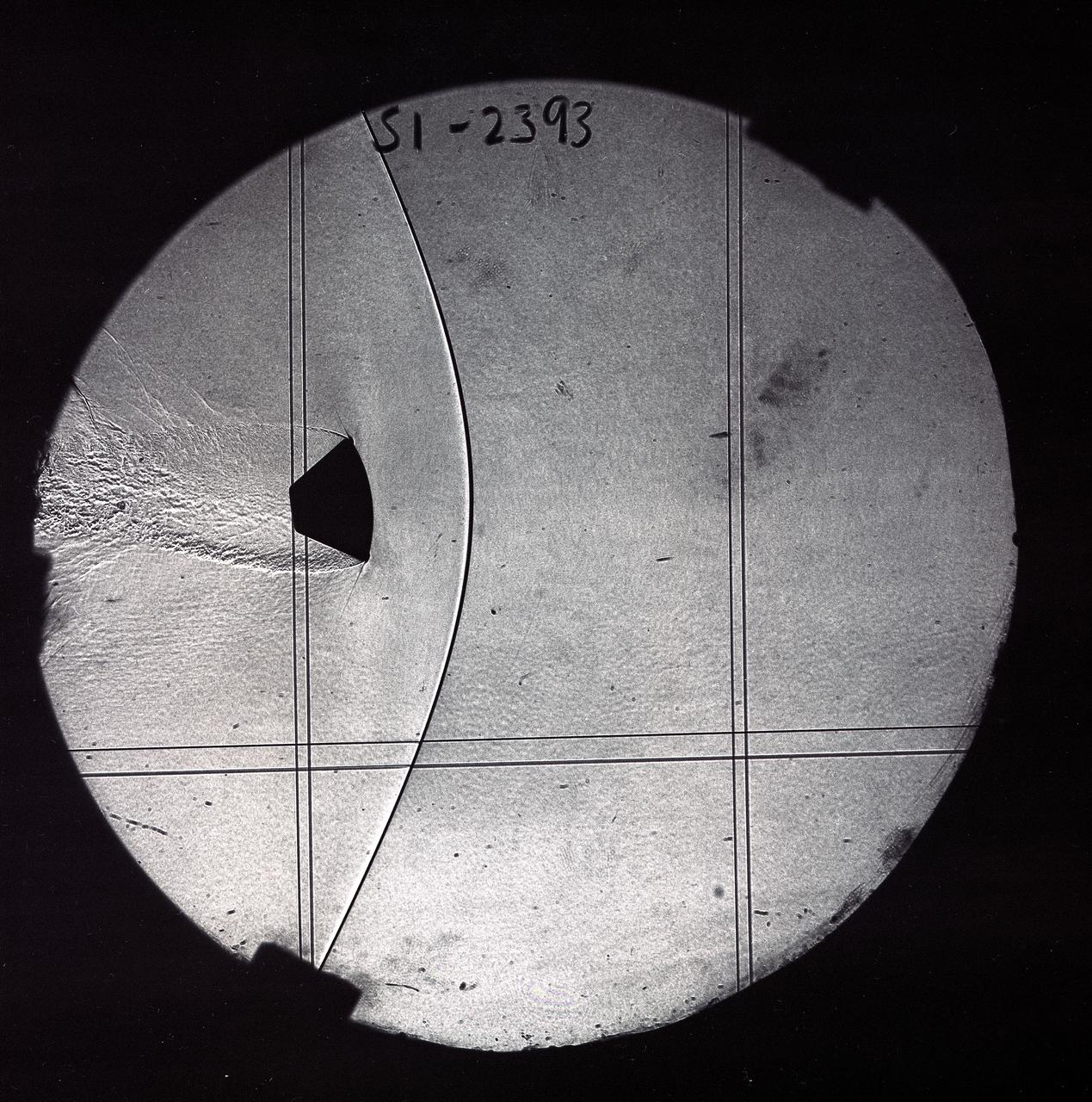
CEV (Crew Escape Vehicle) capsule Balistic Range testing to examine static and dynamic stability characteristics (at the Hypervelocity Free-Flight Facility) HFF - scans of shadowgraphs from 8x10 film images

CEV (Crew Escape Vehicle) capsule Balistic Range testing to examine static and dynamic stability characteristics (at the Hypervelocity Free-Flight Facility) HFF - scans of shadowgraphs from 8x10 film images
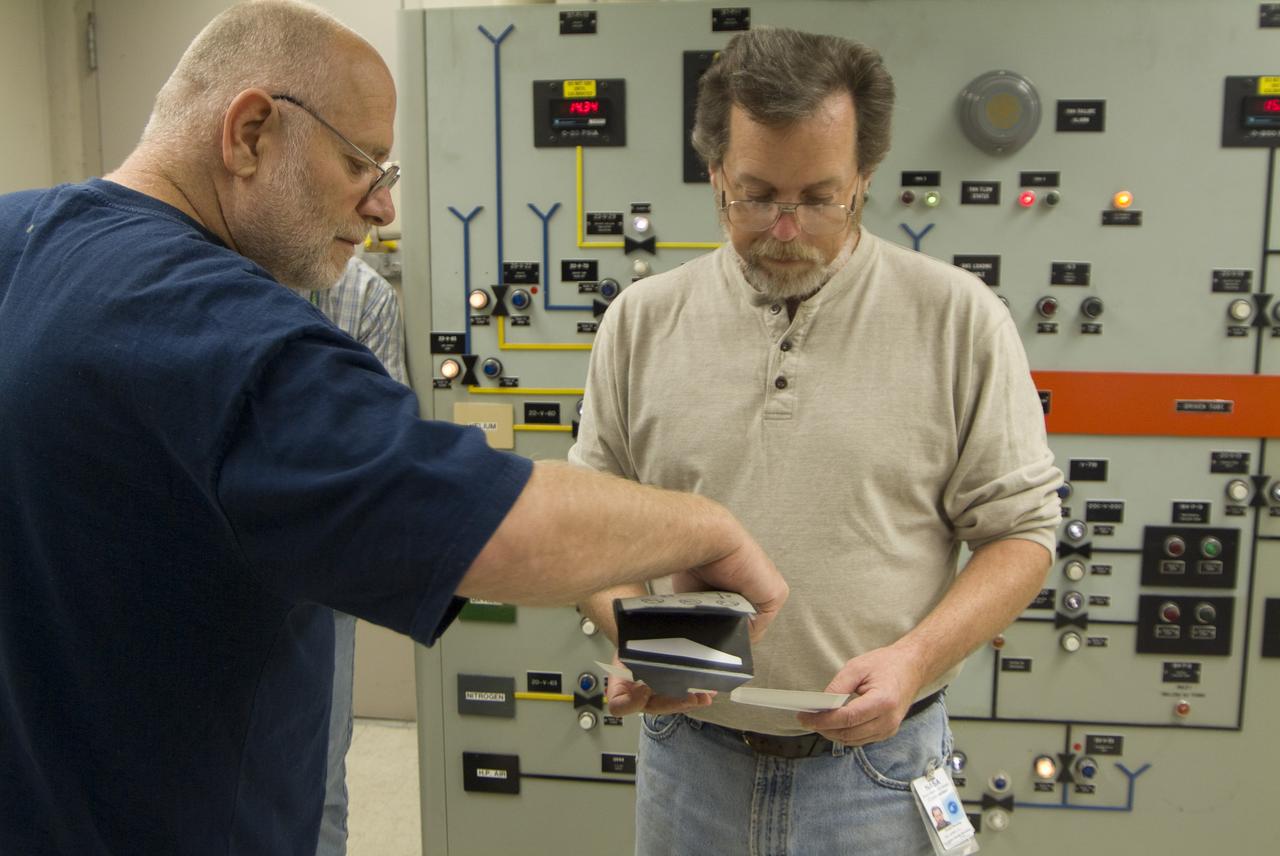
CEV (Crew Escape Vehicle) capsule Balistic Range testing to examine static and dynamic stability characteristics (at the Hypervelocity Free-Flight Facility) HFF - Don Holt (L) & Don Bowling (r) in control room examining poloroids
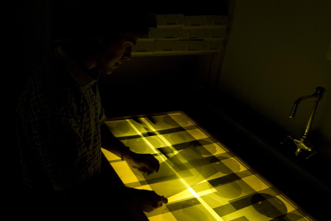
CEV (Crew Escape Vehicle) capsule Balistic Range testing to examine static and dynamic stability characteristics (at the Hypervelocity Free-Flight Facility) HFF - Chuck Cornelison viewing 8x10 shadowgraph images
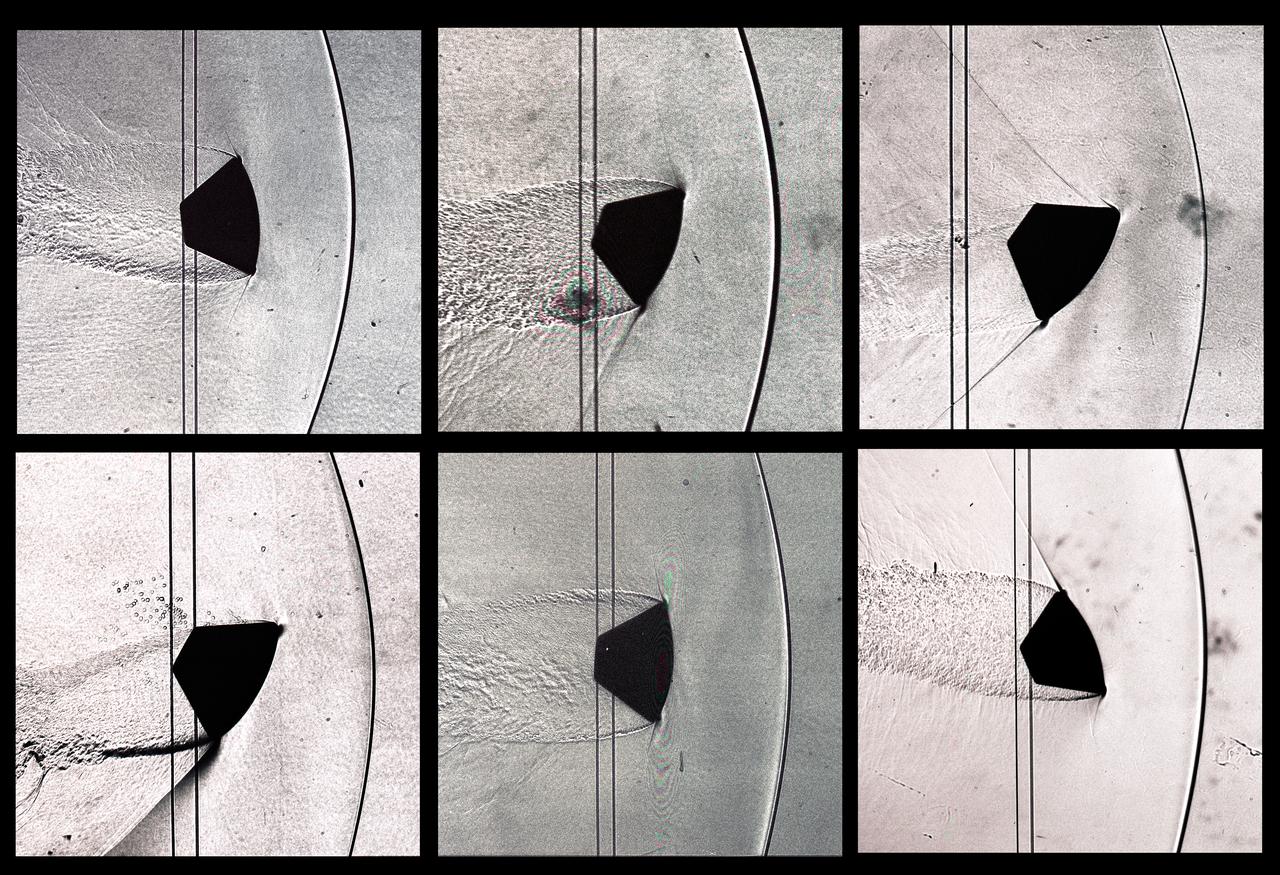
CEV (Crew Escape Vehicle) capsule Balistic Range testing to examine static and dynamic stability characteristics (at the Hypervelocity Free-Flight Facility) HFF - scans of shadowgraphs from 8x10 film images
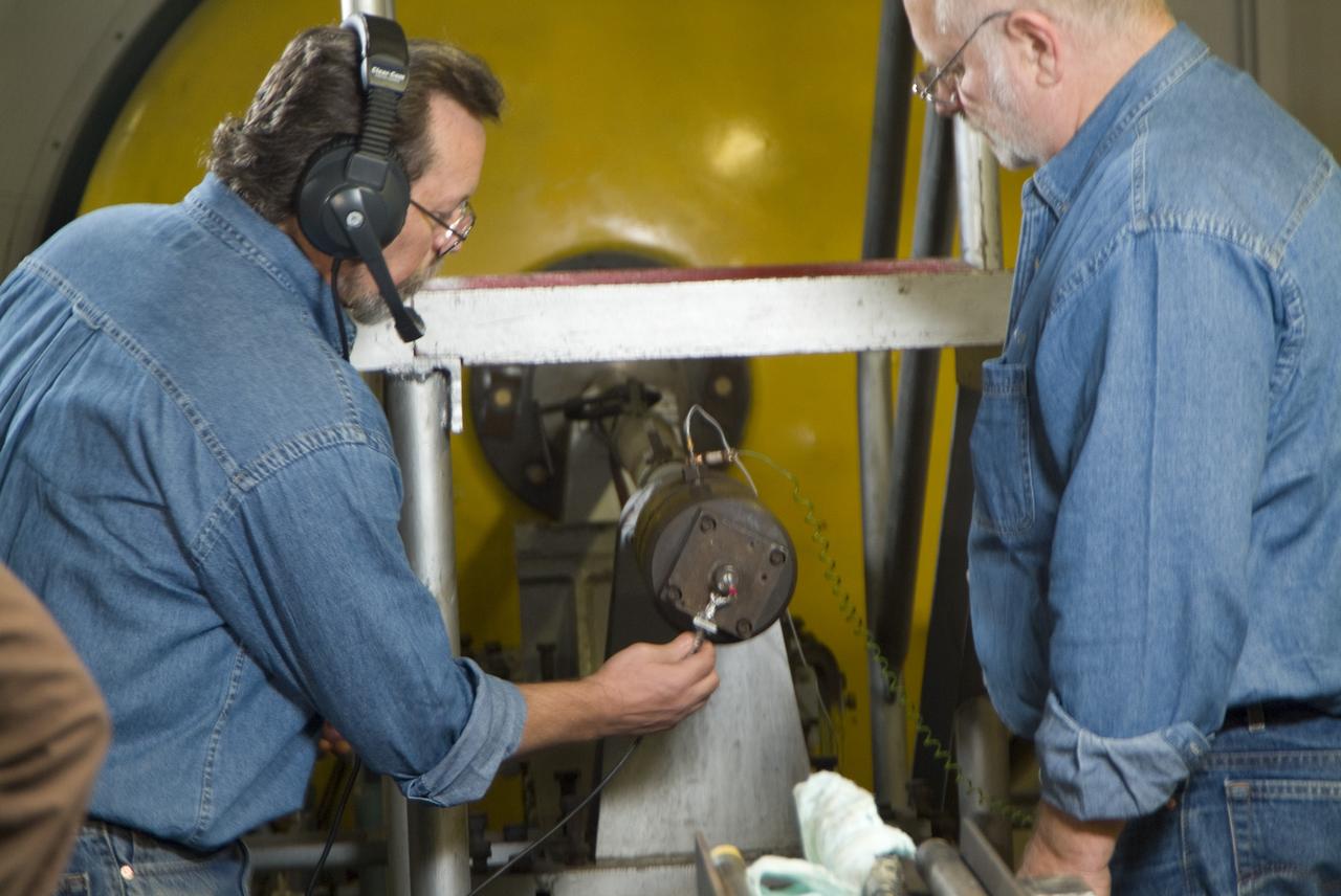
CEV (Crew Escape Vehicle) capsule Balistic Range testing to examine static and dynamic stability characteristics (at the Hypervelocity Free-Flight Facility) HFF - Don Bowling (l) attaching firing cable to breeth cap as Don Holt (r) looks on
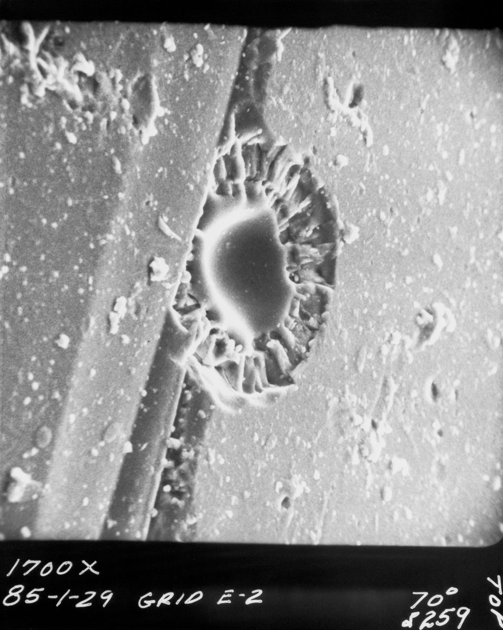
S70-20418 (December 1969) --- Enlarged view shows cosmic dust on broken glass particles, photographed by Dr. G. J. Wasserberg, J. DeVaney and K. Evans at California Institute of Technology during examination of the Apollo 11 lunar material. The photograph was enlarged to 1,700 time its actual size.
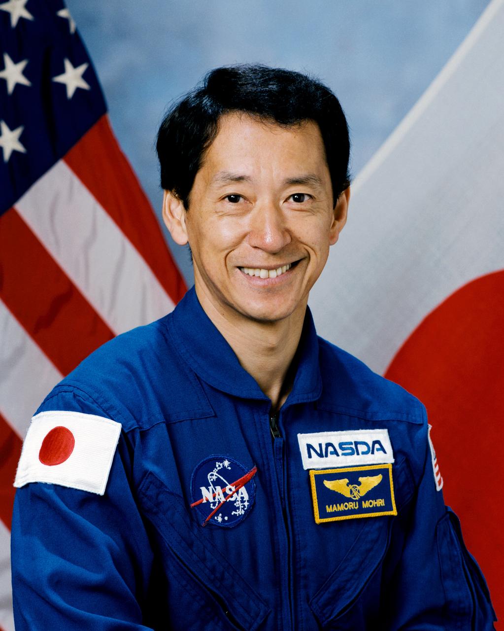
S97-05508 (13 Sept. 1996) --- Astronaut Mamoru Mohri, payload specialist, representing National Space Development Agency (NASDA).
S66-44887 (1 Aug. 1966) --- Single panel from micrometeorite package showing classic hypervelocity impact by micrometeorite particle. Crater is similar to that produced artificially on Earth and by particle impacts on the lunar surface. Particles travel very fast in space and are typically small in size. This impact crater is less than one millimeter in diameter. Photo credit: NASA
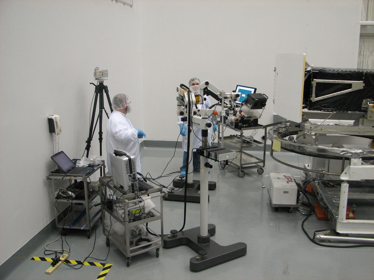
JSC2010-E-054445 (2 July 2009) --- Members of the Orbital Debris Program Office and the Hypervelocity Impact Technology Facility at JSC record images of impact craters and other surface data on the returned Wide Field and Planetary Camera (WFPC-2) of the Hubble Space Telescope. Inspection took place at the Goddard Space Flight Center during the summer of 2009. Photo credit: NASA or National Aeronautics and Space Administration
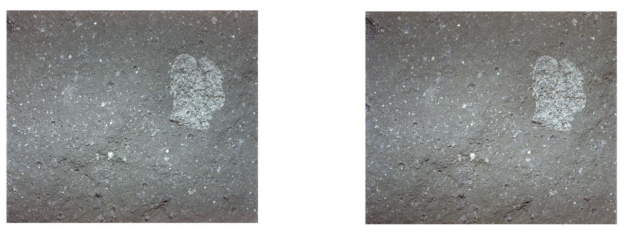
AS11-45-6709 (20 July 1969) --- An Apollo 11 stereo view of the surface of a lunar rock showing an embedded three-fourths inch fragment of a different color. On the surface several small pits are seen; mostly less than one-eighth inch in size, and with a glazed surface. They have a raised rim, characteristic of pits made by high-velocity micro meteorite impacts. The exposure was made by the Apollo 11 35mm stereo close-up camera. The camera was specially developed to get the highest possible resolution of a small area. A three-inch square area is photographed with a flash illumination and at a fixed distance. The camera is mounted on a walking stick, and the astronauts use it by holding it up against the object to be photographed and pulling the trigger. The pictures are in color and give a stereo view, enabling the fine detail to be seen very clearly. The project is under the direction of Professor T. Gold of Cornell University and Mr. F. Pearce of NASA. The camera was designed and built by Eastman Kodak. Professor E. Purcell of Harvard University and Dr. E. Land of the Polaroid Corporation have contributed to the project. The pictures brought back from the moon by the Apollo 11 crew are of excellent quality and allow fine detail of the undisturbed lunar surface to be seen. Scientists hope to be able to deduce from them some of the processes that have taken place that have shaped and modified the surface.
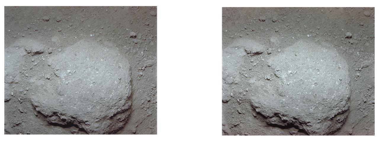
AS11-45-6712 (20 July 1969) --- An Apollo 11 stereo view of a stone, about two and one-half inches long, embedded in the powdery lunar surface material. The little pieces closely around it suggest that it has suffered some erosion. On the surface several small pits are seen, mostly less than one-eighth inch in size, and with a glazed surface. They have a raised rim, characteristic of pits made by the Apollo 11 35mm stereo close-up camera. The camera was specially developed to get the highest possible resolution of a small area. A three-inch square area is photographed with a flash illumination and at a fixed distance. The camera is mounted on a walking stick, and the astronauts use it by holding it up against the object to be photographed and pulling the trigger. The pictures are in color and give a stereo view, enabling the fine detail to be seen very clearly. The project is under the direction of Professor T. Gold of Cornell University and Mr. F. Pearce of NASA. The camera was designed and built by Eastman Kodak. Professor E. Purcell of Harvard University and Dr. E. Land of the Polaroid Corporation have contributed to the project. The pictures brought back from the moon by the Apollo 11 crew are of excellent quality and allow fine detail of the undisturbed lunar surface to be seen. Scientists hope to be able to deduce from them some of the processes that have taken place that have shaped and modified the surface.