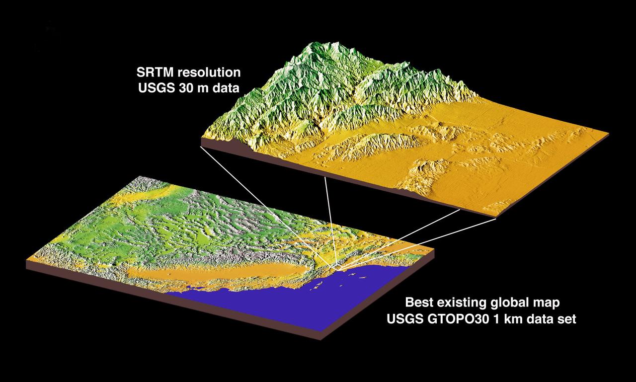
JSC2000E01552 (January 2000) --- This chart compares currently available global map data with the data which will be provided by SRTM during STS-99. The area depicted is the California coast. The SRTM mission will have approximately 1,000 scheduled data takes (every time Endeavour is over land). Data acquisition will be conducted in excess of 80 hours. The recording rate for data will be 180 Mbits/sec for C-band, 90 Mbits/sec for X-band. Total raw radar data will be approximately 9.8 terabytes (15,000 CDs). The mission will utilize some 300 high-density tapes (each tape records 30 min. of C-band, or 60 min. of X-band data).

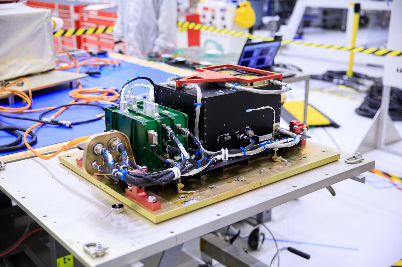
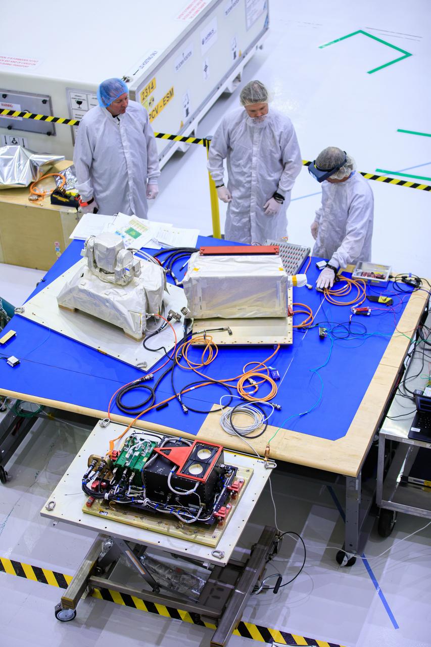
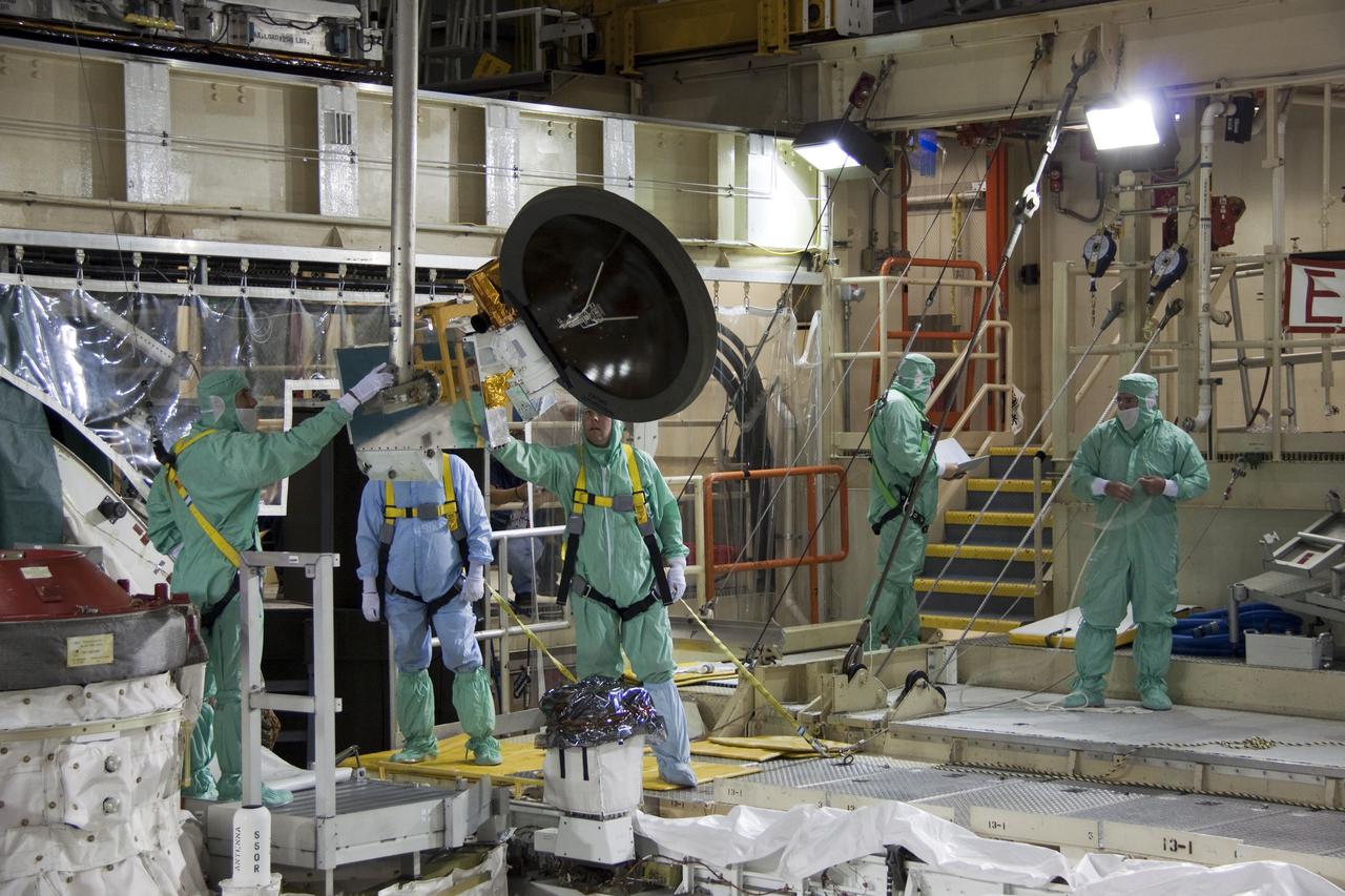
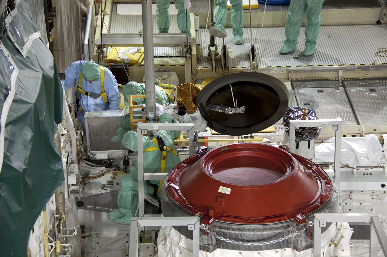
Inside the high bay of the Neil Armstrong Operations and Checkout Building at NASA’s Kennedy Space Center in Florida, technicians assemble on the Optical Communications System for the Artemis II mission on June 2, 2023. Optical communications is the latest space communications technology that is able to provide data rates as much as a hundred times higher than current systems. This will allow astronauts to send and receive ultra-high-definition video from the surface of the Moon or other planets such as Mars. Artemis II will be the first Artemis mission flying crew aboard Orion.
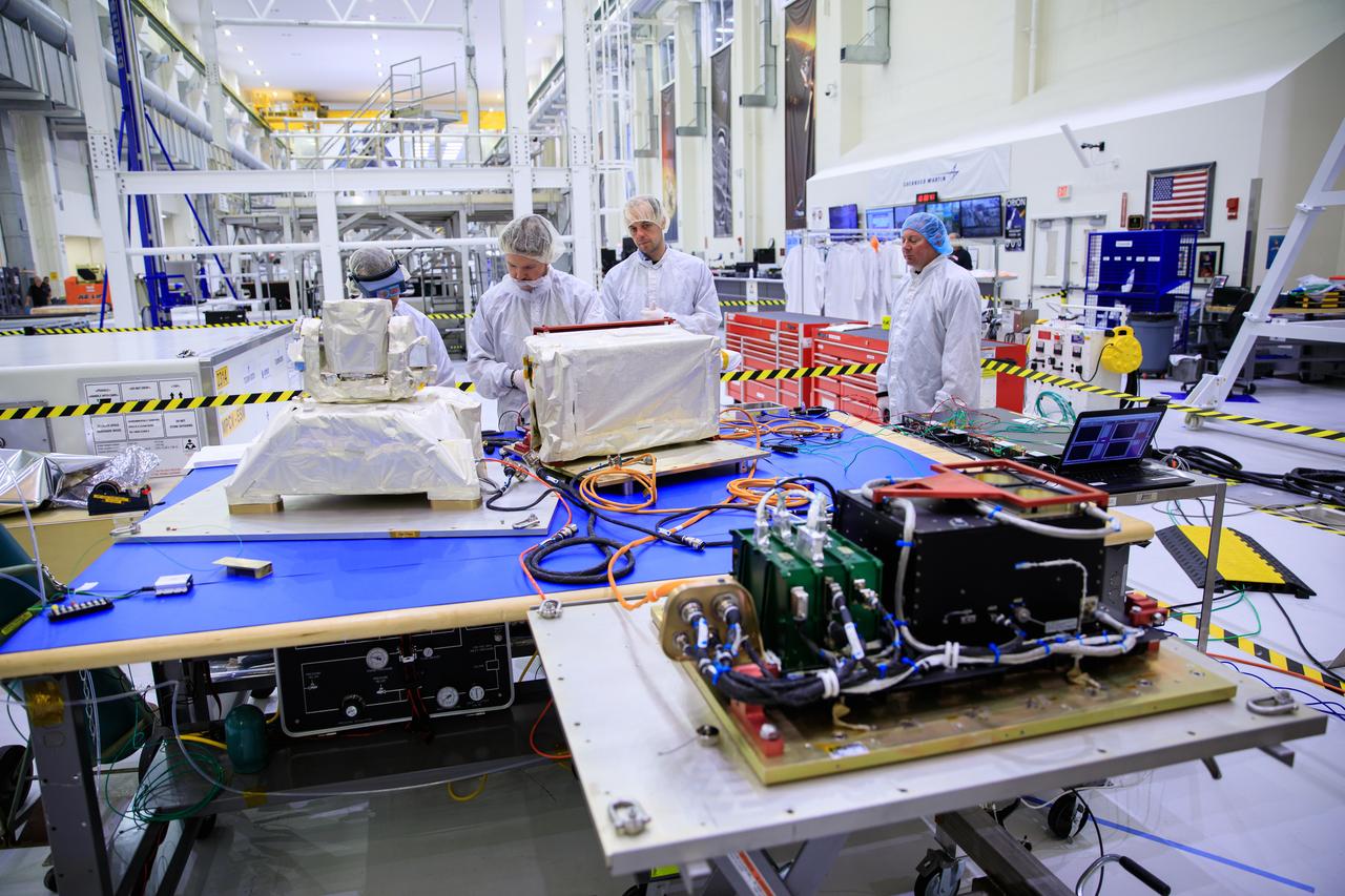
Inside the high bay of the Neil Armstrong Operations and Checkout Building at NASA’s Kennedy Space Center in Florida, technicians assemble on the Optical Communications System for the Artemis II mission on June 2, 2023. Optical communications is the latest space communications technology that is able to provide data rates as much as a hundred times higher than current systems. This will allow astronauts to send and receive ultra-high-definition video from the surface of the Moon or other planets such as Mars. Artemis II will be the first Artemis mission flying crew aboard Orion.
Inside the high bay of the Neil Armstrong Operations and Checkout Building at NASA’s Kennedy Space Center in Florida, technicians assemble on the Optical Communications System for the Artemis II mission on June 2, 2023. Optical communications is the latest space communications technology that is able to provide data rates as much as a hundred times higher than current systems. This will allow astronauts to send and receive ultra-high-definition video from the surface of the Moon or other planets such as Mars. Artemis II will be the first Artemis mission flying crew aboard Orion.
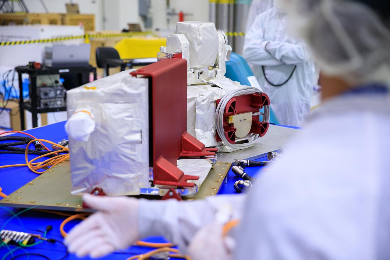
A close-up view of one of the parts of the Optical Communications System for the Artemis II mission inside the Neil Armstrong Operations and Checkout Building high bay on June 2, 2023. Optical communications is the latest space communications technology that is able to provide data rates as much as a hundred times higher than current systems. This will allow astronauts to send and receive ultra-high-definition video from the surface of the Moon or other planets such as Mars. Artemis II will be the first Artemis mission flying crew aboard Orion.
Inside the high bay of the Neil Armstrong Operations and Checkout Building at NASA’s Kennedy Space Center in Florida, technicians assemble on the Optical Communications System for the Artemis II mission on June 2, 2023. Optical communications is the latest space communications technology that is able to provide data rates as much as a hundred times higher than current systems. This will allow astronauts to send and receive ultra-high-definition video from the surface of the Moon or other planets such as Mars. Artemis II will be the first Artemis mission flying crew aboard Orion.

Inside the high bay of the Neil Armstrong Operations and Checkout Building at NASA’s Kennedy Space Center in Florida, technicians work on the Optical Communications System for the Artemis II mission on June 2, 2023. Optical communications is the latest space communications technology that is able to provide data rates as much as a hundred times higher than current systems. This will allow astronauts to send and receive ultra-high-definition video from the surface of the Moon or other planets such as Mars. Artemis II will be the first Artemis mission flying crew aboard Orion.

Inside the high bay of the Neil Armstrong Operations and Checkout Building at NASA’s Kennedy Space Center in Florida, technicians assemble on the Optical Communications System for the Artemis II mission on June 2, 2023. Optical communications is the latest space communications technology that is able to provide data rates as much as a hundred times higher than current systems. This will allow astronauts to send and receive ultra-high-definition video from the surface of the Moon or other planets such as Mars. Artemis II will be the first Artemis mission flying crew aboard Orion.
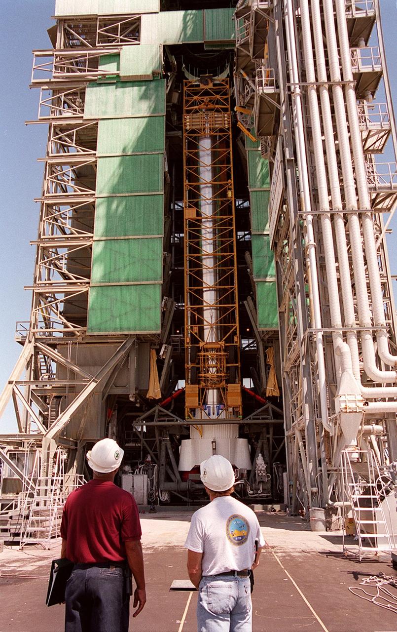
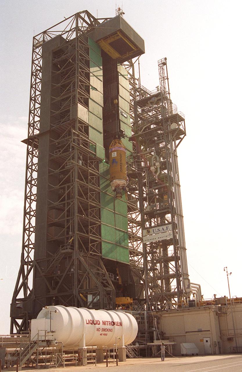
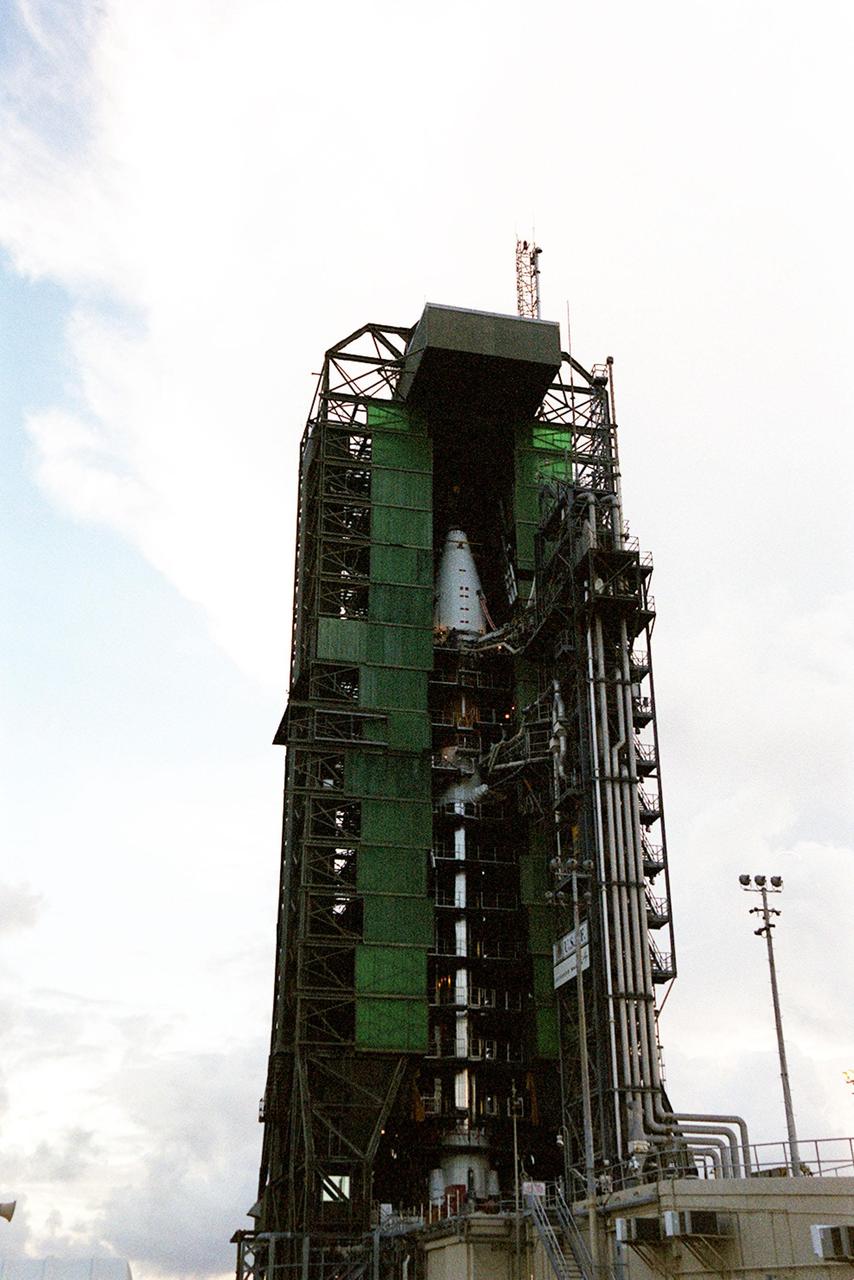
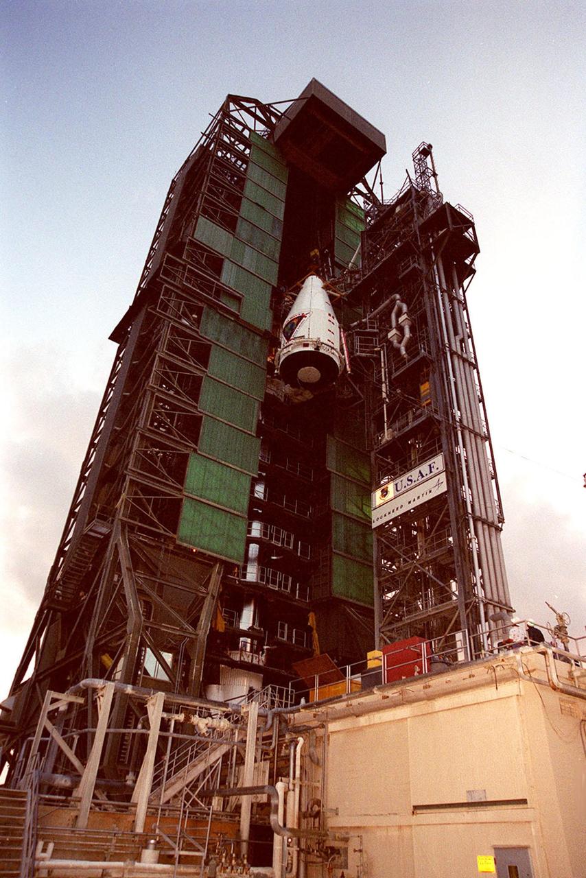
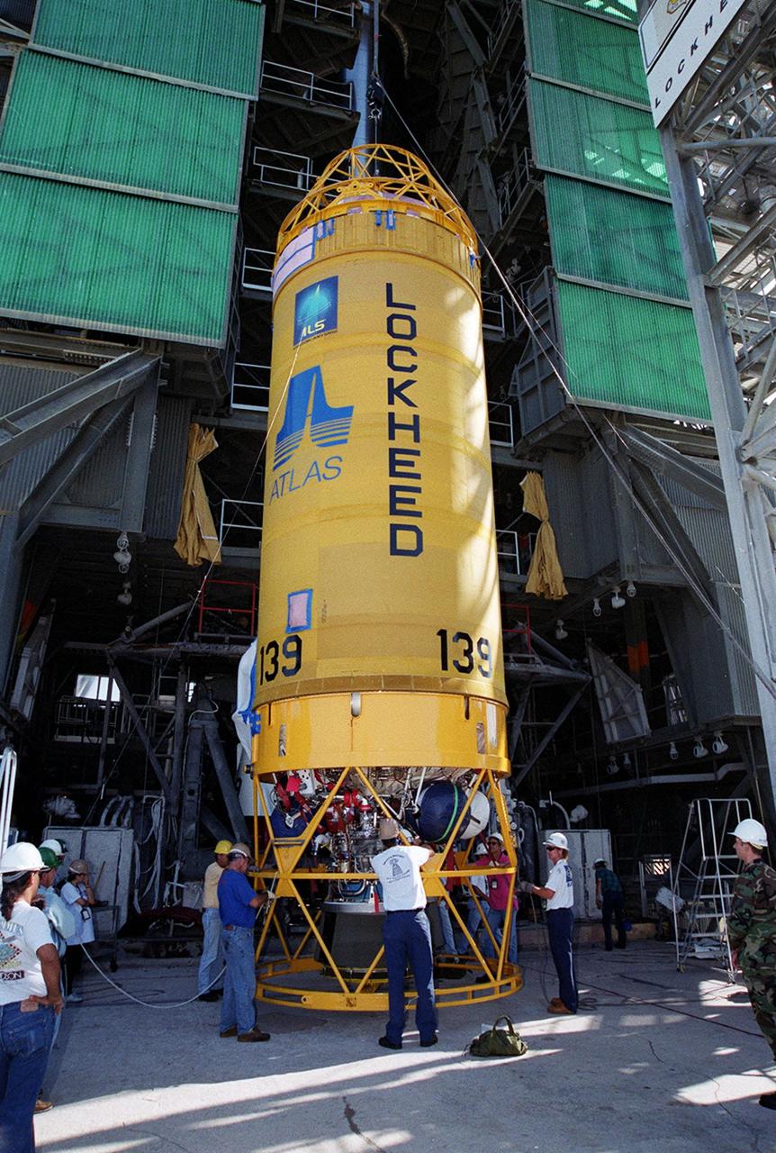
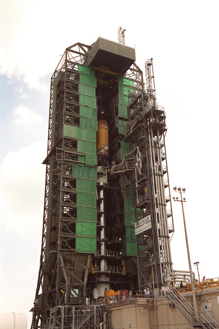
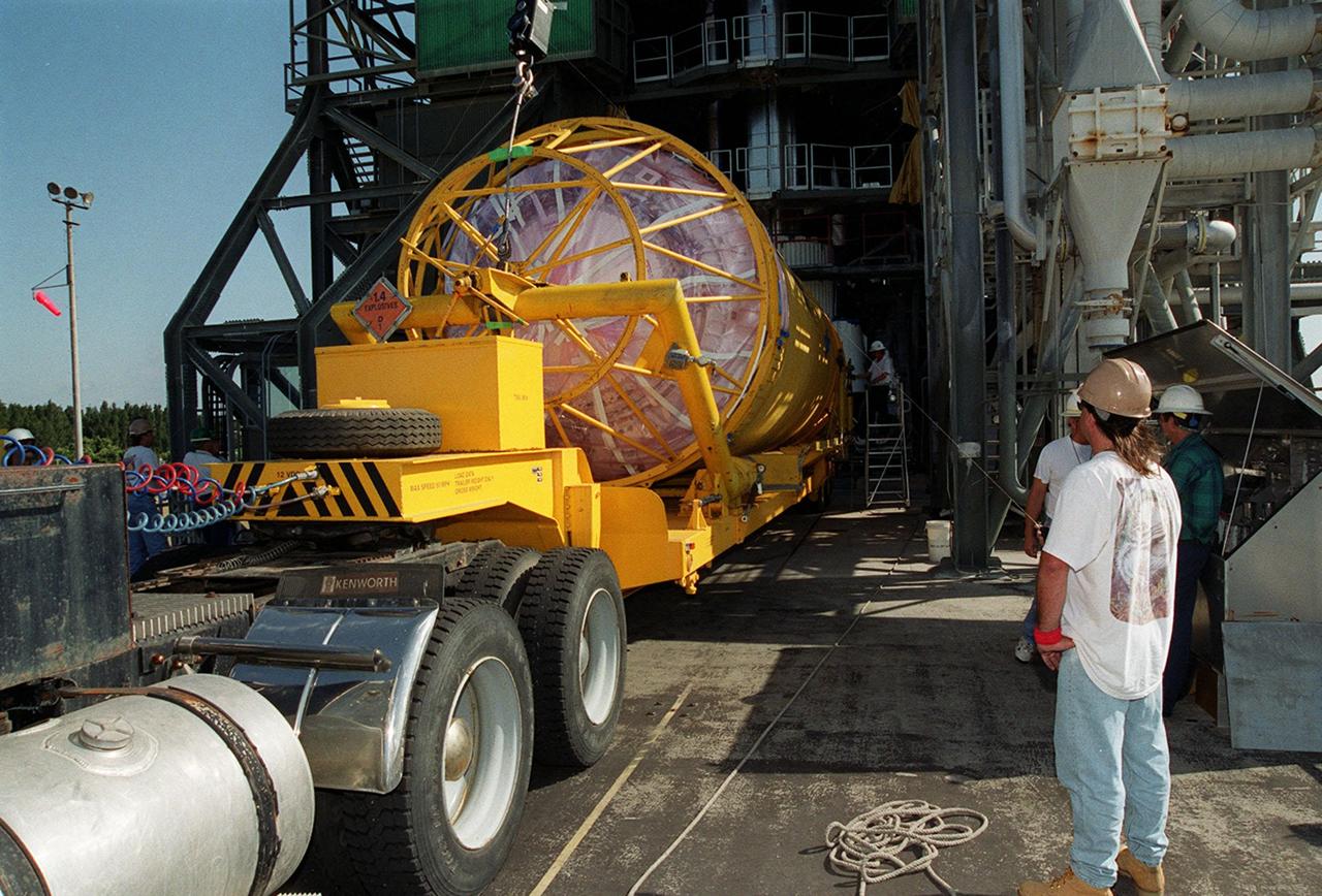
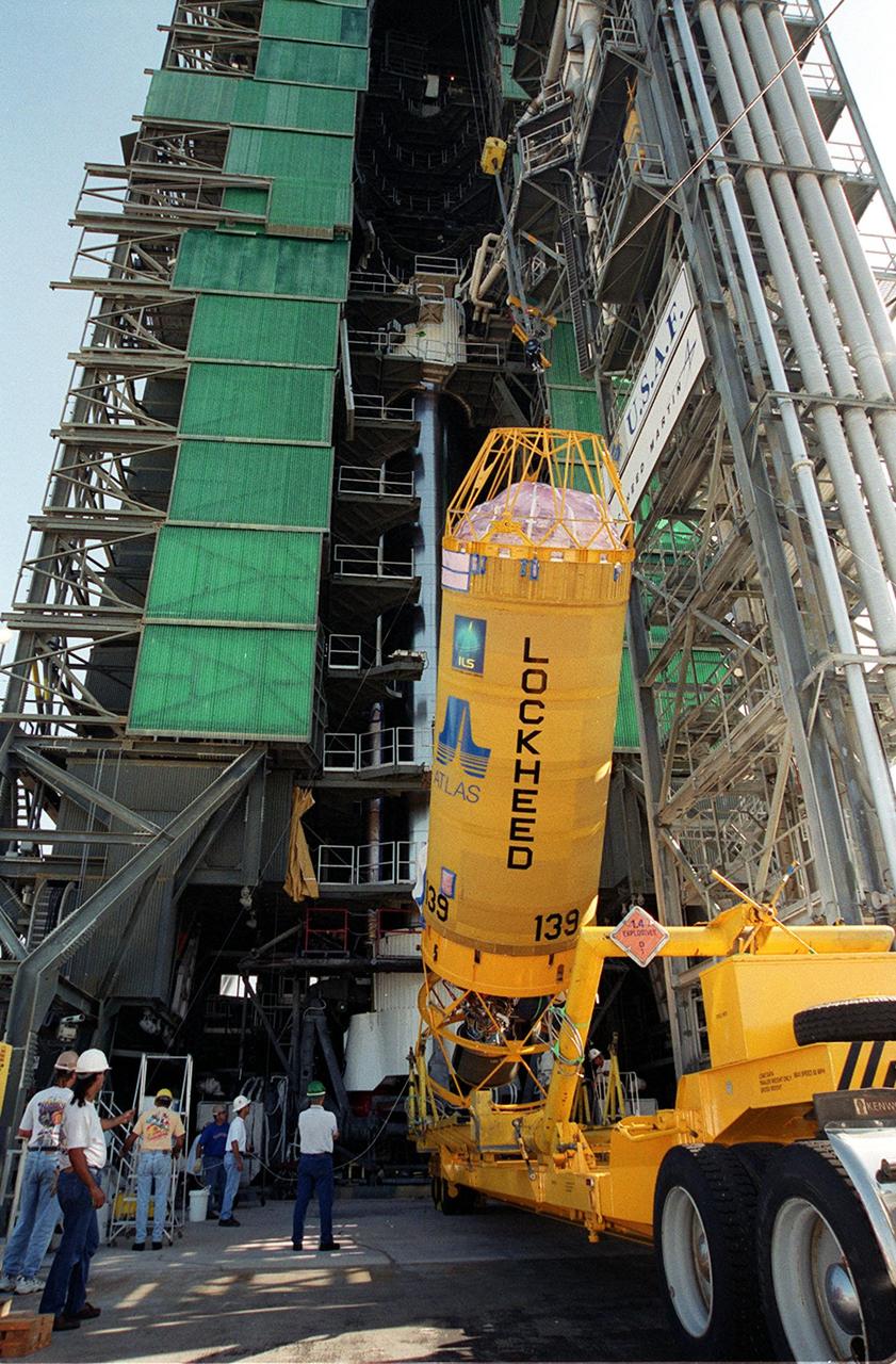
KENNEDY SPACE CENTER, Fla. -- The first (booster) stage of an Atlas II rocket is moved into the launch tower at Pad 36-A, Cape Canaveral Air Force Station. It will later be mated with the Tracking and Data Relay Satellite, known as TDRS-I, for launch in January 2002. The TDRS System (TDRSS) is a communication signal relay system that provides tracking and data acquisition services between low-Earth orbiting spacecraft and NASA/customer control and/or data processing facilities. The system is capable of transmitting to and receiving data from customer spacecrafts over 100 percent of their orbit (some limitations may apply depending on actual orbit). The TDRS-I provides a Ka-band service that will allow customers with extremely high data rates to be supported by the Tracking and Data Relay Satellite System (TDRSS) if they desire

KENNEDY SPACE CENTER, Fla. -- The first (booster) segment of a Lockheed Martin Atlas II rocket sits in the launch tower at Pad 36-A, Cape Canaveral Air Force Station, in preparation for mating with the other stages that will launch the Tracking and Data Relay Satellite, known as TDRS-I, in January 2002. The TDRS System (TDRSS) is a communication signal relay system that provides tracking and data acquisition services between low-Earth orbiting spacecraft and NASA/customer control and/or data processing facilities. The system is capable of transmitting to and receiving data from customer spacecrafts over 100 percent of their orbit (some limitations may apply depending on actual orbit). The TDRS-I provides a Ka-band service that will allow customers with extremely high data rates to be supported by the Tracking and Data Relay Satellite System (TDRSS) if they desire.
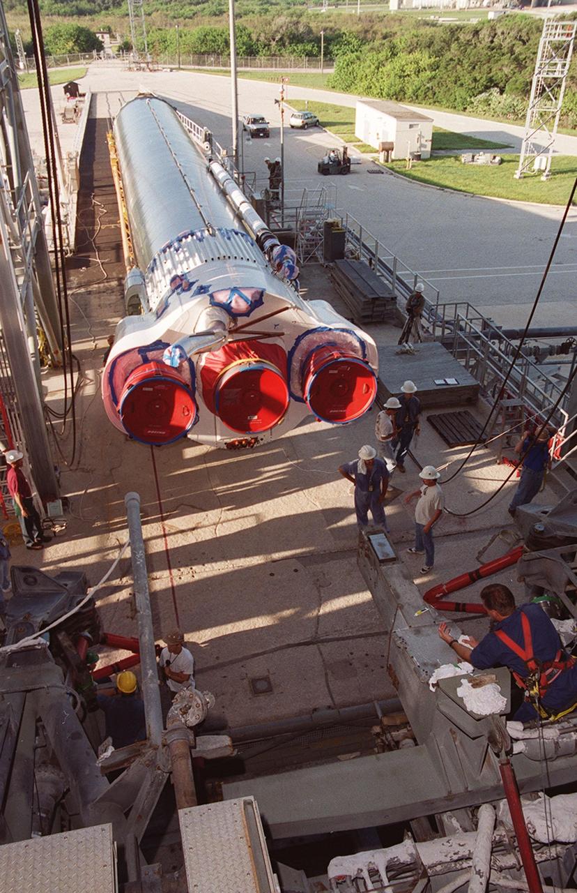
KENNEDY SPACE CENTER, Fla. -- The first (booster) stage of an Atlas II rocket arrives at Pad 36-A, Cape Canaveral Air Force Station. The segment will be lifted and raised into the launch tower where it will be mated with the Tracking and Data Relay Satellite, known as TDRS-I, for launch in January 2002. The TDRS System (TDRSS) is a communication signal relay system that provides tracking and data acquisition services between low-Earth orbiting spacecraft and NASA/customer control and/or data processing facilities. The system is capable of transmitting to and receiving data from customer spacecrafts over 100 percent of their orbit (some limitations may apply depending on actual orbit). The TDRS-I provides a Ka-band service that will allow customers with extremely high data rates to be supported by the Tracking and Data Relay Satellite System (TDRSS) if they desire
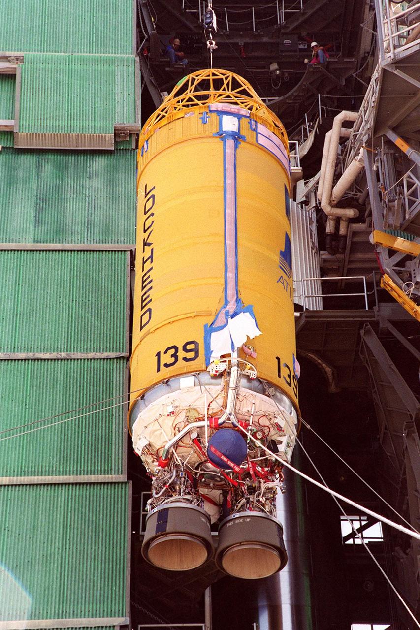
KENNEDY SPACE CENTER, Fla. -- The Lockheed Martin Atlas_Centaur segment of the Atlas II rocket is lowered onto the first (booster) stage of the Atlas II rocket at Launch Pad 36-A, Cape Canaveral Air Force Station. . The rocket is scheduled to launch the Tracking and Data Relay Satellite, known as TDRS-I, in January 2002. The TDRS System (TDRSS) is a communication signal relay system that provides tracking and data acquisition services between low-Earth orbiting spacecraft and NASA_customer control and_or data processing facilities. The system is capable of transmitting to and receiving data from customer spacecrafts over 100 percent of their orbit (some limitations may apply depending on actual orbit). The TDRS-I provides a Ka-band service that will allow customers with extremely high data rates to be supported by the Tracking and Data Relay Satellite System (TDRSS) if they desire.
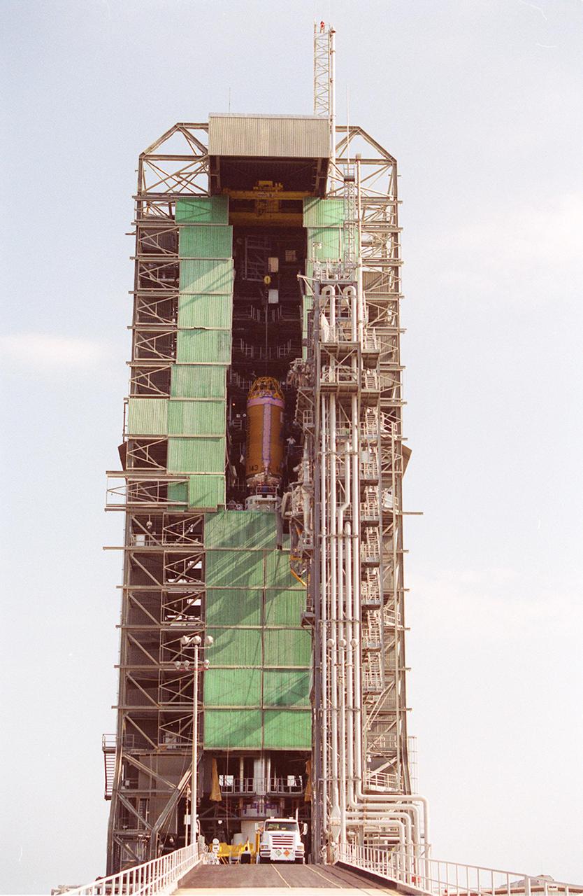
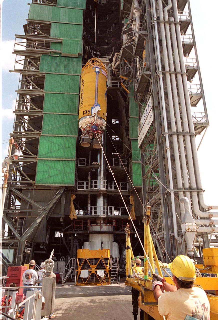
KENNEDY SPACE CENTER, Fla. -- The Lockheed Martin Atlas/Centaur segment of the Atlas II rocket is lifted up the launch tower at Launch Pad 36-A, Cape Canaveral Air Force Station. The rocket is scheduled to launch the Tracking and Data Relay Satellite, known as TDRS-I, in January 2002. The TDRS System (TDRSS) is a communication signal relay system that provides tracking and data acquisition services between low-Earth orbiting spacecraft and NASA/customer control and/or data processing facilities. The system is capable of transmitting to and receiving data from customer spacecrafts over 100 percent of their orbit (some limitations may apply depending on actual orbit). The TDRS-I provides a Ka-band service that will allow customers with extremely high data rates to be supported by the Tracking and Data Relay Satellite System (TDRSS) if they desire.
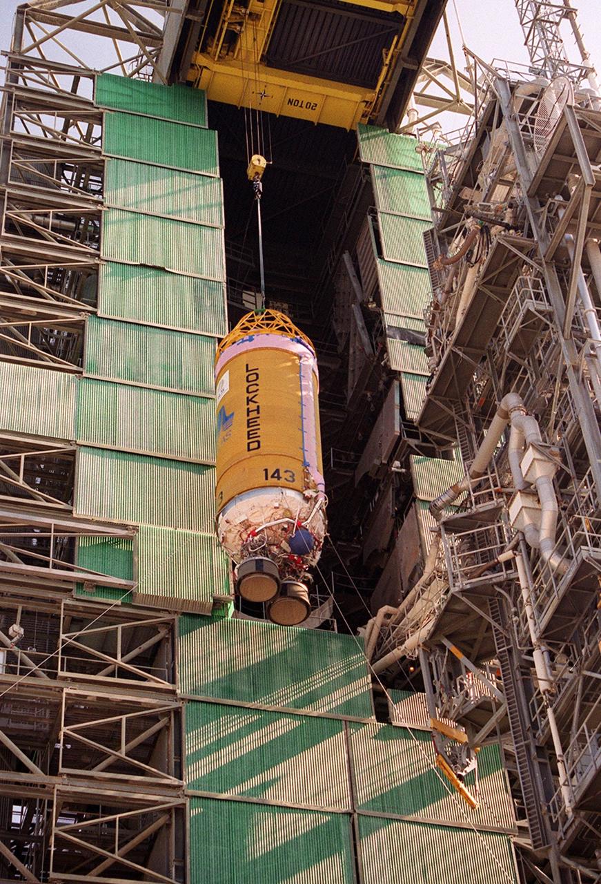
KENNEDY SPACE CENTER, Fla. -- The Lockheed Martin Atlas/Centaur segment of the Atlas II rocket is lifted up the launch tower at Launch Pad 36-A, Cape Canaveral Air Force Station. The rocket is scheduled to launch the Tracking and Data Relay Satellite, known as TDRS-I, in January 2002. The TDRS System (TDRSS) is a communication signal relay system that provides tracking and data acquisition services between low-Earth orbiting spacecraft and NASA/customer control and/or data processing facilities. The system is capable of transmitting to and receiving data from customer spacecrafts over 100 percent of their orbit (some limitations may apply depending on actual orbit). The TDRS-I provides a Ka-band service that will allow customers with extremely high data rates to be supported by the Tracking and Data Relay Satellite System (TDRSS) if they desire.
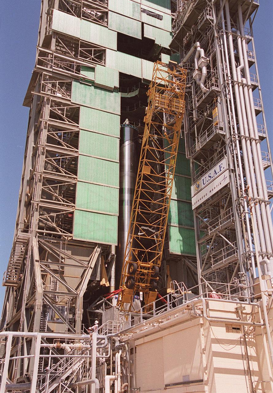
KENNEDY SPACE CENTER, Fla. - At Pad 36-A, Cape Canaveral Air Force Station, the equipment used to raise the Atlas II first (booster) stage into the launch tower is removed. The Atlas II will later be mated with the Tracking and Data Relay Satellite, known as TDRS-I, for launch in January 2002. The TDRS System (TDRSS) is a communication signal relay system that provides tracking and data acquisition services between low-Earth orbiting spacecraft and NASA_customer control and_or data processing facilities. The system is capable of transmitting to and receiving data from customer spacecrafts over 100 percent of their orbit (some limitations may apply depending on actual orbit). The TDRS-I provides a Ka-band service that will allow customers with extremely high data rates to be supported by the Tracking and Data Relay Satellite System (TDRSS) if they desire
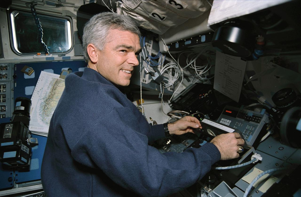
STS059-09-012 (9-20 April 1994) --- On the Space Shuttle Endeavour's aft flight deck, astronaut Michael R. (Rich) Clifford, mission specialist, inserts a tape in the payload high rate recorder. Three of these state-of-the-art recorders captured four times the amount of data that could be radioed to the ground. The 183 tapes, each containing 40 megabytes of data, will be turned into images over the next year, and analyzed over the next decade. Clifford was joined in space by five other NASA astronauts for a week and a half of support to the Space Radar Laboratory (SRL-1)/STS-59 mission.

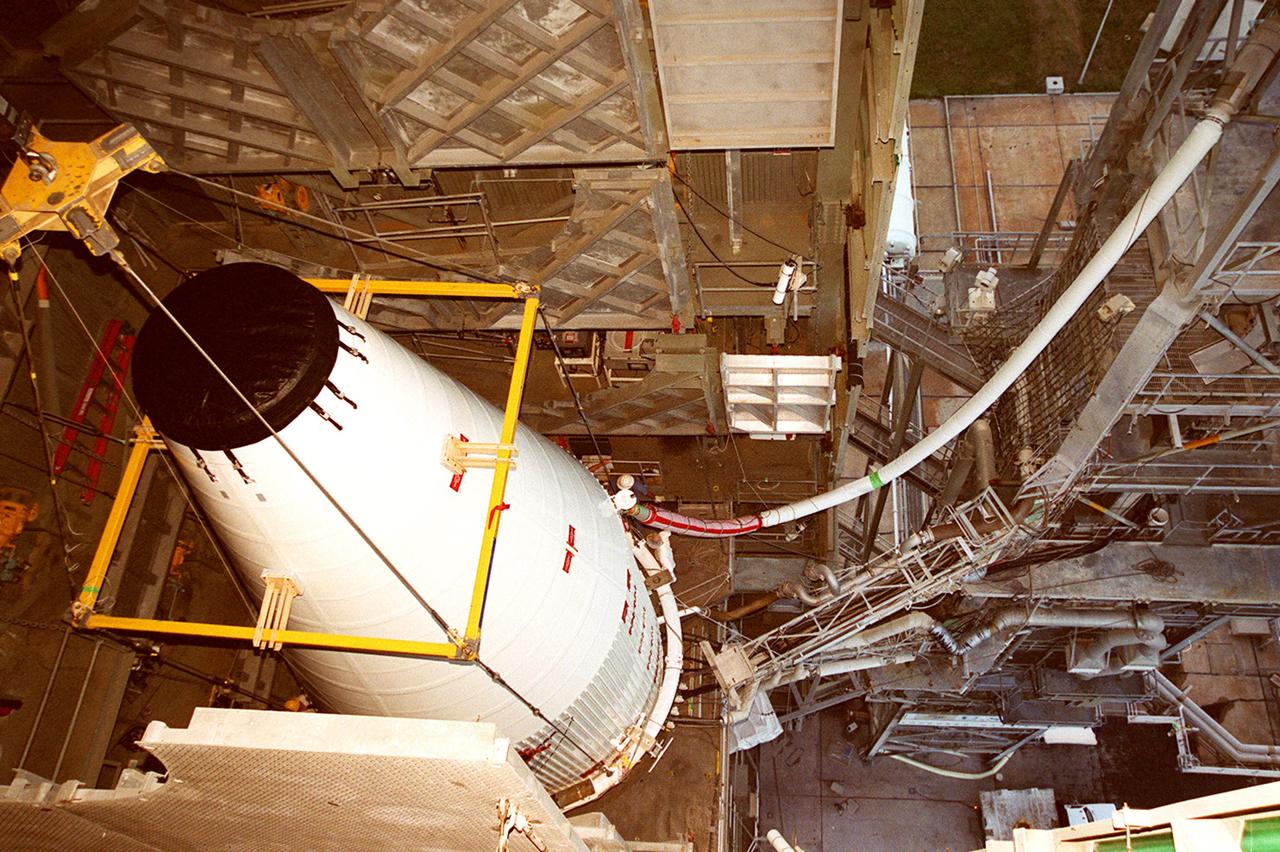
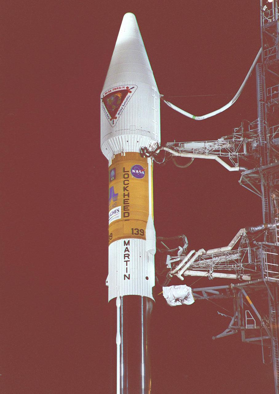
KENNEDY SPACE CENTER, FLA. -- In a view taken near the top of the launch tower at Launch Pad 36A, Cape Canaveral Air Force Station, the nose fairing with the Tracking and Data Relay Satellite (TDRS-H) inside is hoisted up the tower by the overhead crane (left). The fairing will be mated with the Atlas IIA/Centaur rocket, which is already stacked, for launch on June 29. The satellite will augment the TDRS system's existing S- and Ku-band frequencies by adding Ka-band capability. TDRS will serve as the sole means of continuous, high-data-rate communications with the Space Shuttle, with the International Space Station upon its completion, and with dozens of unmanned scientific satellites in low-earth orbit.
The nose fairing covering the Tracking and Data Relay Satellite (TDRS-H) is close to the top of the launch tower at Launch Pad 36A, Cape Canaveral Air Force Station. It is being lifted to mate with the Atlas IIA/Centaur rocket, which is already stacked, for launch on June 29. The satellite will augment the TDRS system’s existing Sand Ku-band frequencies by adding Ka-band capability. TDRS will serve as the sole means of continuous, high-data-rate communication with the Space Shuttle, with the International Space Station upon its completion, and with dozens of unmanned scientific satellites in low earth orbit

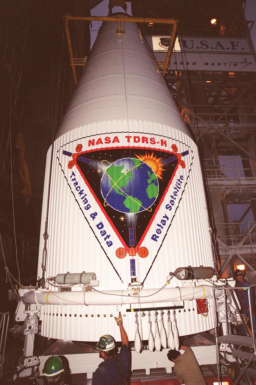
At Launch Pad 36A, Cape Canaveral Air Force Station, workers (at left) oversee the lifting of the nose fairing covering the Tracking and Data Relay Satellite (TDRS-H). Once at the top, the fairing will be mated with the Atlas IIA/Centaur rocket, which is already stacked, for launch on June 29. The satellite will augment the TDRS system’s existing Sand Ku-band frequencies by adding Ka-band capability. TDRS will serve as the sole means of continuous, high-data-rate communication with the Space Shuttle, with the International Space Station upon its completion, and with dozens of unmanned scientific satellites in low earth orbit

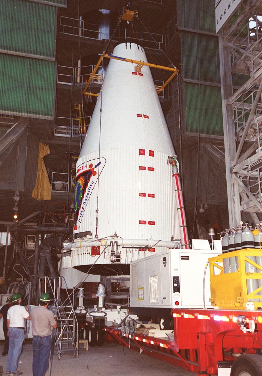
An overhead crane is positioned on the nose fairing covering the Tracking and Data Relay Satellite (TDRS-H) in order to lift it up the tower at Launch Pad 36A, Cape Canaveral Air Force Station. It will be mated with the Atlas IIA/Centaur rocket, which is already stacked, for launch on June 29. The satellite will augment the TDRS system’s existing Sand Ku-band frequencies by adding Ka-band capability. TDRS will serve as the sole means of continuous, high-data-rate communication with the Space Shuttle, with the International Space Station upon its completion, and with dozens of unmanned scientific satellites in low earth orbit
KENNEDY SPACE CENTER, FLA. -- In a view taken near the top of the launch tower at Launch Pad 36A, Cape Canaveral Air Force Station, the nose fairing with the Tracking and Data Relay Satellite (TDRS-H) inside is hoisted up the tower by the overhead crane (left). The fairing will be mated with the Atlas IIA/Centaur rocket, which is already stacked, for launch on June 29. The satellite will augment the TDRS system's existing S- and Ku-band frequencies by adding Ka-band capability. TDRS will serve as the sole means of continuous, high-data-rate communications with the Space Shuttle, with the International Space Station upon its completion, and with dozens of unmanned scientific satellites in low-earth orbit.

The nose fairing covering the Tracking and Data Relay Satellite (TDRS-H) nears the top of the launch tower at Launch Pad 36A, Cape Canaveral Air Force Station. It will be mated with the Atlas IIA/Centaur rocket, which is already stacked (barely visible behind the framework on lower left), for launch on June 29. The satellite will augment the TDRS system’s existing Sand Ku-band frequencies by adding Ka-band capability. TDRS will serve as the sole means of continuous, high-data-rate communication with the Space Shuttle, with the International Space Station upon its completion, and with dozens of unmanned scientific satellites in low earth orbit
An overhead crane is positioned on the nose fairing covering the Tracking and Data Relay Satellite (TDRS-H) in order to lift it up the tower at Launch Pad 36A, Cape Canaveral Air Force Station. It will be mated with the Atlas IIA/Centaur rocket, which is already stacked, for launch on June 29. The satellite will augment the TDRS system’s existing Sand Ku-band frequencies by adding Ka-band capability. TDRS will serve as the sole means of continuous, high-data-rate communication with the Space Shuttle, with the International Space Station upon its completion, and with dozens of unmanned scientific satellites in low earth orbit

The nose fairing covering the Tracking and Data Relay Satellite (TDRS-H) is close to the top of the launch tower at Launch Pad 36A, Cape Canaveral Air Force Station. It is being lifted to mate with the Atlas IIA/Centaur rocket, which is already stacked, for launch on June 29. The satellite will augment the TDRS system’s existing Sand Ku-band frequencies by adding Ka-band capability. TDRS will serve as the sole means of continuous, high-data-rate communication with the Space Shuttle, with the International Space Station upon its completion, and with dozens of unmanned scientific satellites in low earth orbit
At Launch Pad 36A, Cape Canaveral Air Force Station, workers (at left) oversee the lifting of the nose fairing covering the Tracking and Data Relay Satellite (TDRS-H). Once at the top, the fairing will be mated with the Atlas IIA/Centaur rocket, which is already stacked, for launch on June 29. The satellite will augment the TDRS system’s existing Sand Ku-band frequencies by adding Ka-band capability. TDRS will serve as the sole means of continuous, high-data-rate communication with the Space Shuttle, with the International Space Station upon its completion, and with dozens of unmanned scientific satellites in low earth orbit
The nose fairing covering the Tracking and Data Relay Satellite (TDRS-H) nears the top of the launch tower at Launch Pad 36A, Cape Canaveral Air Force Station. It will be mated with the Atlas IIA/Centaur rocket, which is already stacked (barely visible behind the framework on lower left), for launch on June 29. The satellite will augment the TDRS system’s existing Sand Ku-band frequencies by adding Ka-band capability. TDRS will serve as the sole means of continuous, high-data-rate communication with the Space Shuttle, with the International Space Station upon its completion, and with dozens of unmanned scientific satellites in low earth orbit
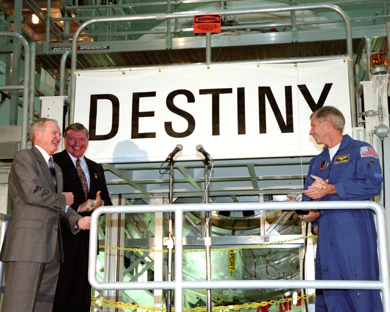
KENNEDY SPACE CENTER, FLA. - In the Space Station Processing Facility, Center Director Roy Bridges (left), Program Manager of the International Space Station (ISS) Randy Brinkley (second from left) and STS-98 Commander Ken Cockrell (right) applaud the unveiling of the name "Destiny" for the U.S. Laboratory module. The lab, which is behnd them on a workstand, is scheduled to be launched on STS-98 on Space Shuttle Endeavour in early 2000. It will become the centerpiece of scientific research on the ISS. The Shuttle will spend six days docked to the Station while the laboratory is attached and three spacewalks are conducted to compete its assembly. The laboratory will be launched with five equipment racks aboard, which will provide essential functions for Station systems, including high data-rate communications, and maintain the Station's orientation using control gyroscopes launched earlier. Additional equipment and research racks will be installed in the laboratory on subsequent Shuttle flights.
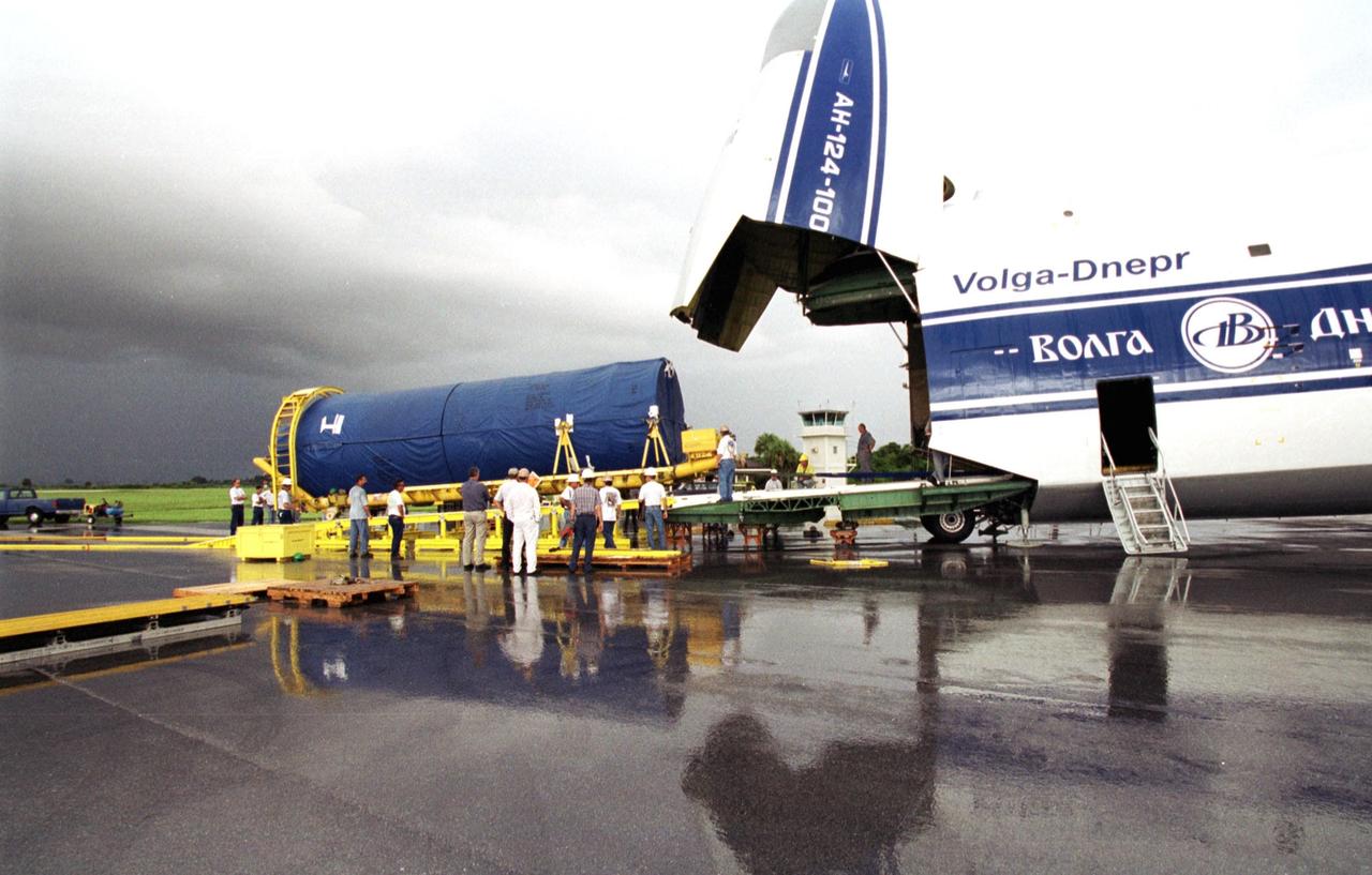
KENNEDY SPACE CENTER, FLA. - At Cape Canaveral Air Force Station, Fla., the Atlas Centaur booster segment of an Atlas II rocket is offloaded. It will be mated to the first segment on Launch Pad 36-A, CCAFS, in preparation for launch of the TDRS-I spacecraft Oct. 30. The 40-minute launch window begins at 11:19 p.m. EST. The TDRS System (TDRSS) is a communication signal relay system that provides tracking and data acquisition services between low-Earth orbiting spacecraft and NASA/customer control and/or data processing facilities. The system is capable of transmitting to and receiving data from customer spacecrafts over 100 percent of their orbit (some limitations may apply depending on actual orbit). The TDRS-I provides a Ka-band service that will allow customers with extremely high data rates to be supported by TDRSS if they desire
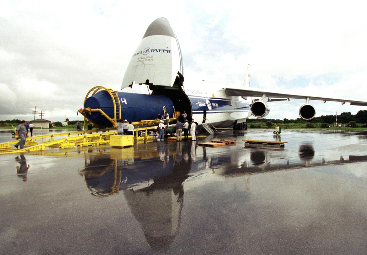
KENNEDY SPACE CENTER, FLA. - At Cape Canaveral Air Force Station, Fla., the Atlas Centaur booster segment of an Atlas II rocket is offloaded. It will be mated to the first segment on Launch Pad 36-A, CCAFS, in preparation for launch of the TDRS-I spacecraft Oct. 30. The 40-minute launch window begins at 11:19 p.m. EST. The TDRS System (TDRSS) is a communication signal relay system that provides tracking and data acquisition services between low-Earth orbiting spacecraft and NASA/customer control and/or data processing facilities. The system is capable of transmitting to and receiving data from customer spacecrafts over 100 percent of their orbit (some limitations may apply depending on actual orbit). The TDRS-I provides a Ka-band service that will allow customers with extremely high data rates to be supported by TDRSS if they desire
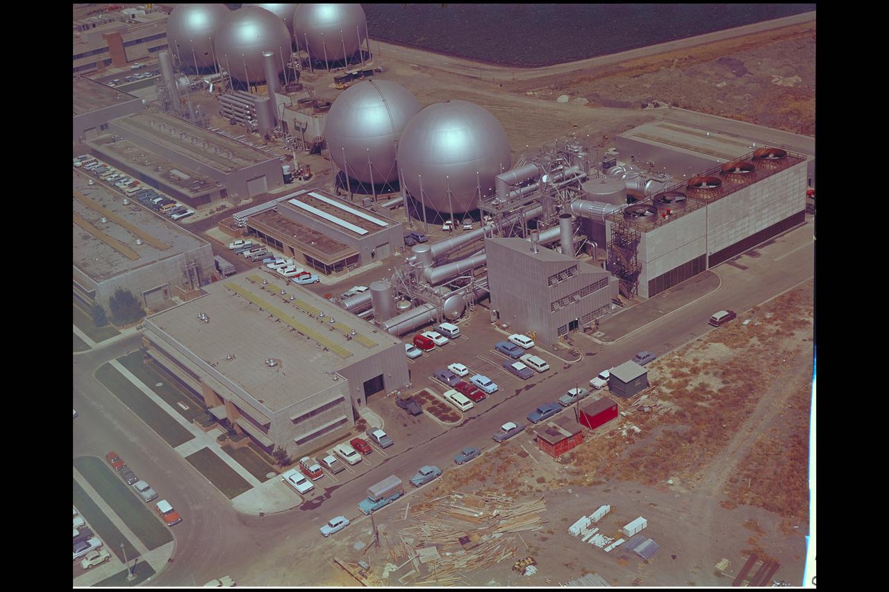
Aerial view of Gasdynamics facility in 1964 and the 20 inch helium tunnel Part of the Thermal Protection Laboratory used to research materials for heat shield applications and for aerodynamic heating and materials studies of vehicles in planetary atmospheres. This laboratory is comprised of five separate facilities: an Aerodynamic Heating Tunnel, a Heat Transfer Tunnel, two Supersonic Turbulent Ducts, and a High-Power CO2 Gasdynamic Laser. All these facilities are driven by arc-heaters, with the exception of the large, combustion-type laser. The arc-heated facilities are powered by a 20 Megawatt DC power supply. Their effluent gas stream (test gases; Air, N2, He, CO2 and mixtures; flow rates from 0.05 to 5.0 lbs/sec) discharges into a five-stage stream-ejector-driven vacuum system. The vacuum system and power supply are common to the test faciities in building N-238. All of the facilities have high pressure water available at flow rates up to 4, 000 gals/min. The data obtained from these facilities are recorded on magnetic tape or oscillographs. All forms of data can be handled whether from thermo-couples, pressure cells, pyrometers, or radiometers, etc. in addition, closed circuit T. V. monitors and various film cameras are available. (operational since 1962)

CRAY AND SP-2 COMPUTERS
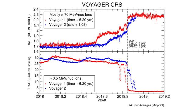
These graphs compare data from identical instruments onboard NASA's Voyager 1 and Voyager 2 spacecraft as they each exited the heliosphere. Voyager 1 exited in 2012, and Voyager 2 exited in 2018. The cosmic ray subsystem (CRS) measures the rate of energetic particles hitting the radiation detector on the instrument. The top graph shows high energy particles (called cosmic rays) that originate outside the heliosphere. The CRS instruments on both spacecraft observed similar, but not identical, increases in the cosmic ray rate as they both crossed the heliopause (the outer edge of the heliosphere). The lower graph shows slightly lower energy particles that originate inside the heliosphere. Both spacecraft detected a similar but not identical decrease in these lower energy particles when they crossed the heliopause and immediately after. https://photojournal.jpl.nasa.gov/catalog/PIA22916
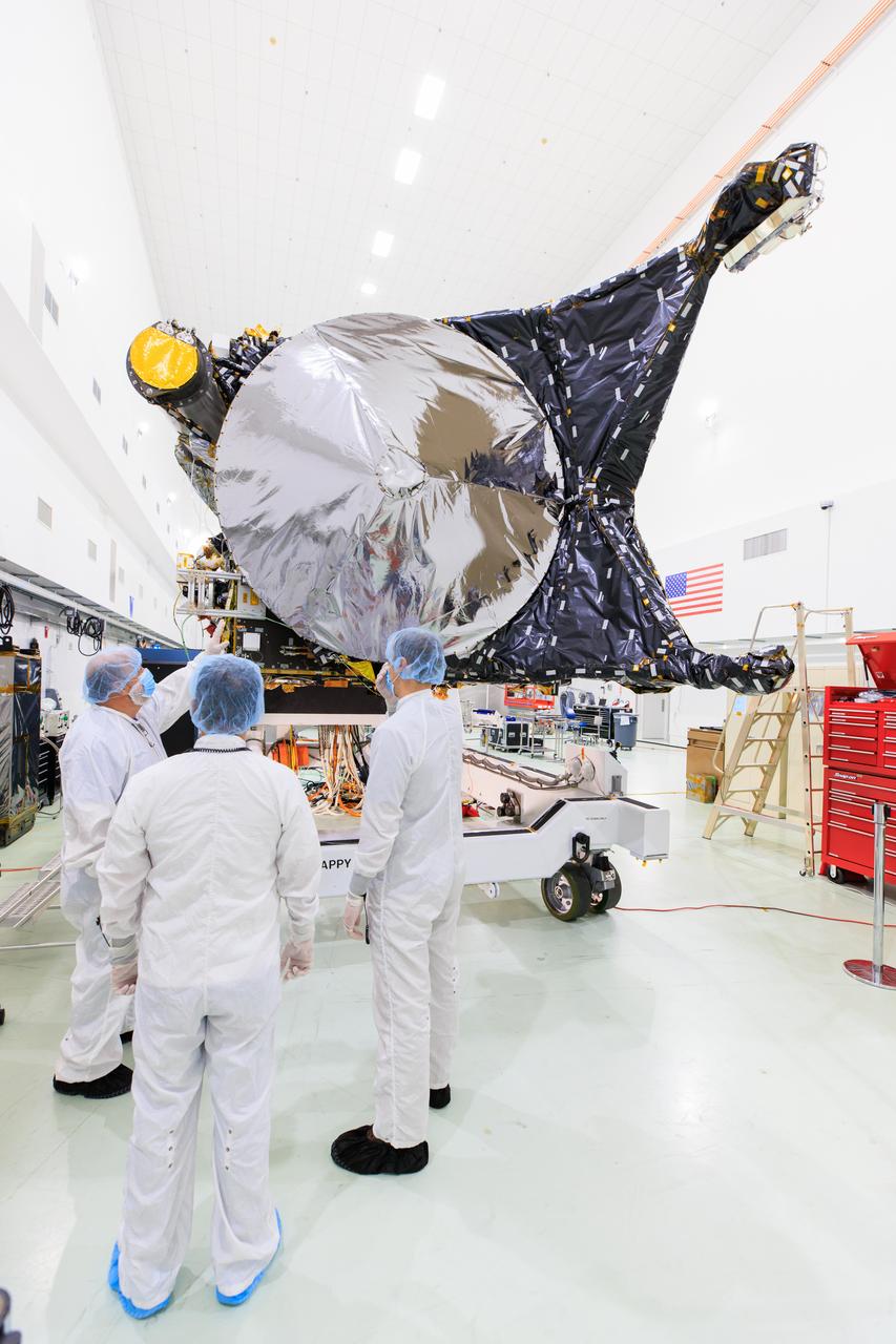
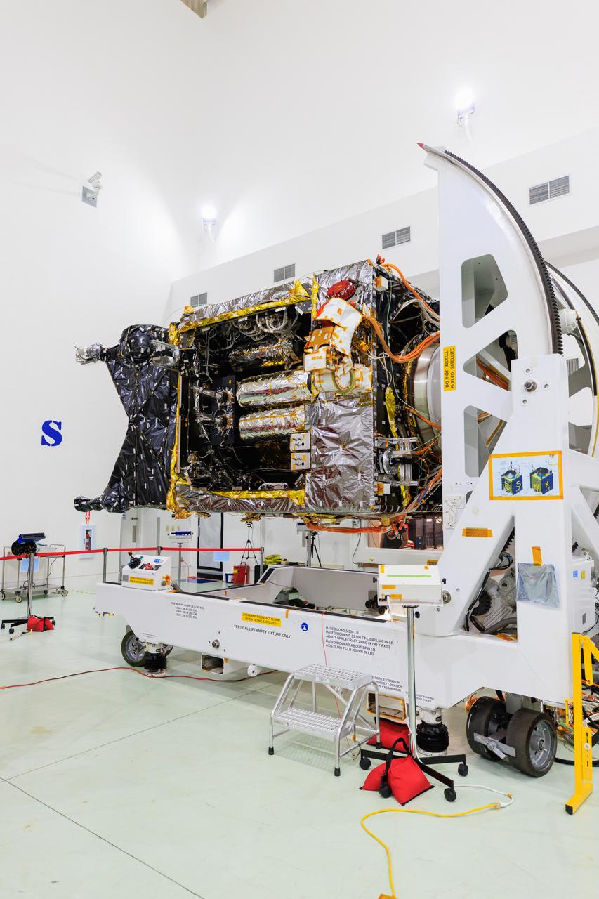
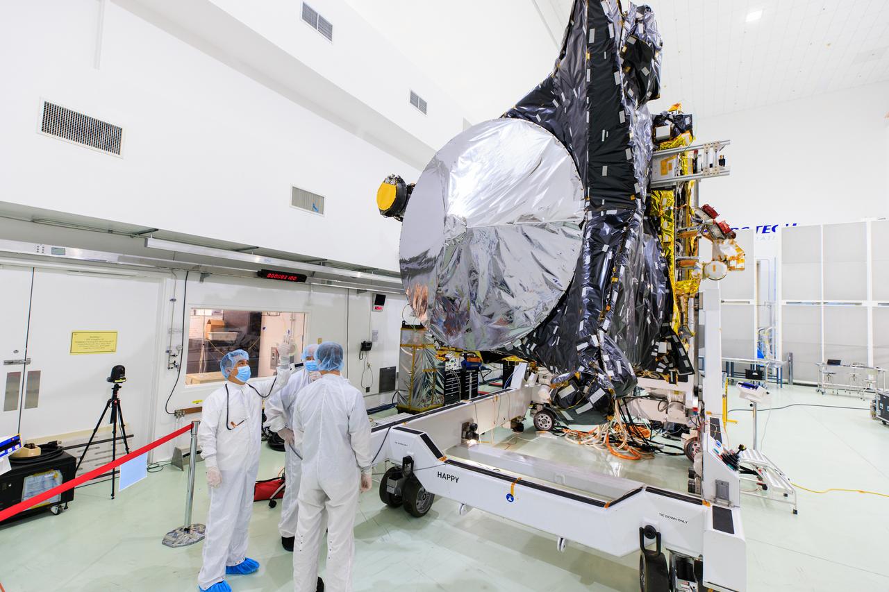
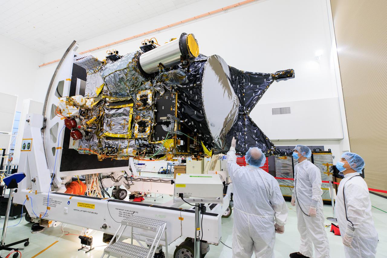
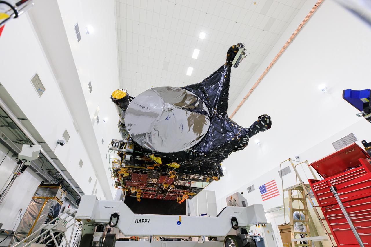
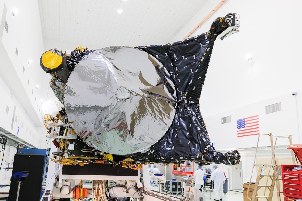
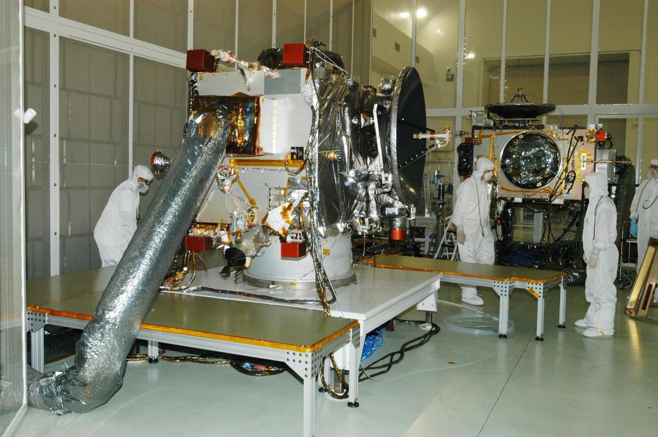
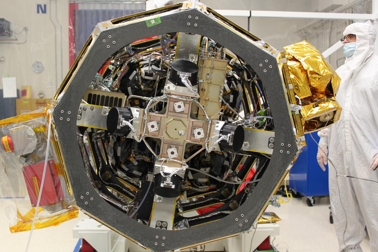
NASA's Psyche spacecraft is shown in a clean room on June 26, 2023, at Astrotech Space Operations Facility near the agency’s Kennedy Space Center in Florida. Engineers and technicians from NASA’s Jet Propulsion Laboratory in Southern California have begun final assembly, test, and launch operations on Psyche, with assembly of the spacecraft all but complete except for the installation of the solar arrays and the imagers. NASA’s Deep Space Optical Communications (DSOC) technology demonstration, testing high-data-rate laser communications, remains integrated into the spacecraft. A final suite of tests will be run on the vehicle, after which it will be fueled and then mated onto a SpaceX Falcon Heavy rocket just prior to launch, targeted for October 2023.
NASA's Psyche spacecraft is shown in a clean room on June 26, 2023, at Astrotech Space Operations Facility near the agency’s Kennedy Space Center in Florida. Engineers and technicians from NASA’s Jet Propulsion Laboratory in Southern California have begun final assembly, test, and launch operations on Psyche, with assembly of the spacecraft all but complete except for the installation of the solar arrays and the imagers. NASA’s Deep Space Optical Communications (DSOC) technology demonstration, testing high-data-rate laser communications, remains integrated into the spacecraft. A final suite of tests will be run on the vehicle, after which it will be fueled and then mated onto a SpaceX Falcon Heavy rocket just prior to launch, targeted for October 2023.

NASA's Psyche spacecraft is shown in a clean room on June 26, 2023, at Astrotech Space Operations Facility near the agency’s Kennedy Space Center in Florida. Engineers and technicians from NASA’s Jet Propulsion Laboratory in Southern California have begun final assembly, test, and launch operations on Psyche, with assembly of the spacecraft all but complete except for the installation of the solar arrays and the imagers. NASA’s Deep Space Optical Communications (DSOC) technology demonstration, testing high-data-rate laser communications, remains integrated into the spacecraft. A final suite of tests will be run on the vehicle, after which it will be fueled and then mated onto a SpaceX Falcon Heavy rocket just prior to launch, targeted for October 2023.
CAPE CANAVERAL, Fla. -- Technicians install a new Ku-Band communications system antenna on space shuttle Discovery in Orbiter Processing Facility-3 at NASA's Kennedy Space Center in Florida. The antenna is used to transmit and receive high data rate communications, such as video, and is being replaced for the STS-133 mission to the International Space Station. During its STS-131 mission to the station in April, Discovery's Ku-Band failed to operate in orbit. As a result, video of the thermal protection system inspection had to be recorded aboard Discovery and transmitted to the ground after the shuttle docked with the station. Typically, the inspection video is simultaneously transmitted live to the ground and recorded aboard the shuttle for later review. NASA_Charisse Nahser
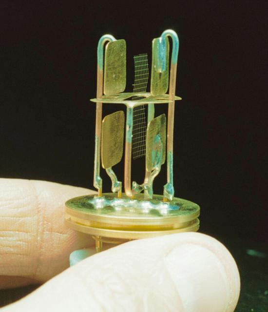
The Critical Viscosity of Xenon Experiment (CVX-2) on the STS-107 Research 1 mission in 2002 will measure the viscous behavior of liquid xenon, a heavy inert gas used in flash lamps and ion rocket engines, at its critical point. Resembling a tiny bit of window screen, the oscillator at the heart of CVX-2 will vibrate between two pairs of paddle-like electrodes. The slight bend in the shape of the mesh has no effect on the data. What counts are the mesh's displacement in the xenon fluid and the rate at which the displacement dampens. The unit shown here is encased in a small test cell and capped with a sapphire windown to contain the xenon at high pressure.
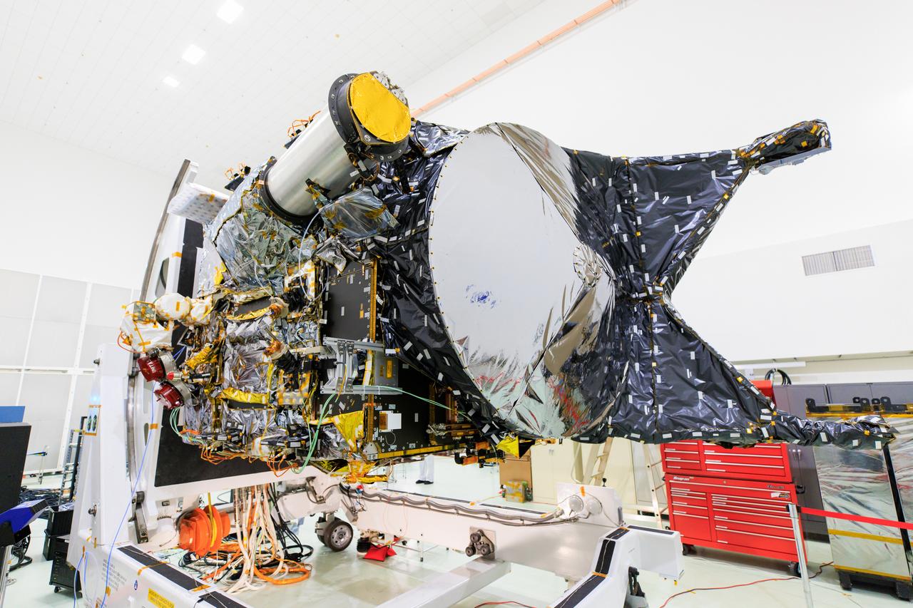
NASA's Psyche spacecraft is shown in a clean room on June 26, 2023, at Astrotech Space Operations Facility near the agency’s Kennedy Space Center in Florida. Engineers and technicians from NASA’s Jet Propulsion Laboratory in Southern California have begun final assembly, test, and launch operations on Psyche, with assembly of the spacecraft all but complete except for the installation of the solar arrays and the imagers. NASA’s Deep Space Optical Communications (DSOC) technology demonstration, testing high-data-rate laser communications, remains integrated into the spacecraft. A final suite of tests will be run on the vehicle, after which it will be fueled and then mated onto a SpaceX Falcon Heavy rocket just prior to launch, targeted for October 2023.
CAPE CANAVERAL, Fla. -- Technicians install a new Ku-Band communications system antenna on space shuttle Discovery in Orbiter Processing Facility-3 at NASA's Kennedy Space Center in Florida. The antenna is used to transmit and receive high data rate communications, such as video, and is being replaced for the STS-133 mission to the International Space Station. During its STS-131 mission to the station in April, Discovery's Ku-Band failed to operate in orbit. As a result, video of the thermal protection system inspection had to be recorded aboard Discovery and transmitted to the ground after the shuttle docked with the station. Typically, the inspection video is simultaneously transmitted live to the ground and recorded aboard the shuttle for later review. NASA_Charisse Nahser
CAPE CANAVERAL, Fla. -- A new Ku-Band communications system antenna is installed on space shuttle Discovery in Orbiter Processing Facility-3 at NASA's Kennedy Space Center in Florida. The antenna is used to transmit and receive high data rate communications, such as video, and is being replaced for the STS-133 mission to the International Space Station. During its STS-131 mission to the station in April, Discovery's Ku-Band failed to operate in orbit. As a result, video of the thermal protection system inspection had to be recorded aboard Discovery and transmitted to the ground after the shuttle docked with the station. Typically, the inspection video is simultaneously transmitted live to the ground and recorded aboard the shuttle for later review. NASA_Charisse Nahser
CAPE CANAVERAL, Fla. -- A new Ku-Band communications system antenna is ready to be installed on space shuttle Discovery in Orbiter Processing Facility-3 at NASA's Kennedy Space Center in Florida. The antenna is used to transmit and receive high data rate communications, such as video, and is being replaced for the STS-133 mission to the International Space Station. During its STS-131 mission to the station in April, Discovery's Ku-Band failed to operate in orbit. As a result, video of the thermal protection system inspection had to be recorded aboard Discovery and transmitted to the ground after the shuttle docked with the station. Typically, the inspection video is simultaneously transmitted live to the ground and recorded aboard the shuttle for later review. NASA_Charisse Nahser
NASA's Psyche spacecraft is shown in a clean room on June 26, 2023, at Astrotech Space Operations Facility near the agency’s Kennedy Space Center in Florida. Engineers and technicians from NASA’s Jet Propulsion Laboratory in Southern California have begun final assembly, test, and launch operations on Psyche, with assembly of the spacecraft all but complete except for the installation of the solar arrays and the imagers. NASA’s Deep Space Optical Communications (DSOC) technology demonstration, testing high-data-rate laser communications, remains integrated into the spacecraft. A final suite of tests will be run on the vehicle, after which it will be fueled and then mated onto a SpaceX Falcon Heavy rocket just prior to launch, targeted for October 2023.
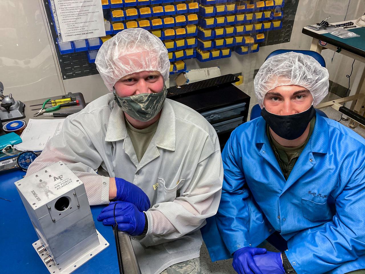
jsc2021e048047 (2/19/2021) --- Captain Hayden Richards (left) and Cadet Madison Yates (Right) with the flight unit of Falcon Neuro. Lightning and sprites are related forms of electrical discharges in Earth’s atmosphere. Space Test Program-Houston 7-Falcon Neuro (STP-H7-Falcon Neuro) demonstrates using event-based sensors (EBSs) to detect lightning in cloud tops and electrical discharges in the middle atmosphere. EBSs provide the high-speed optical sensing needed to capture such brief phenomena and data rates fast enough for making these observations from space. This technology could improve understanding of atmospheric electrical phenomena. Image courtesy of United States Air Force Academy.
NASA's Psyche spacecraft is shown in a clean room on June 26, 2023, at Astrotech Space Operations Facility near the agency’s Kennedy Space Center in Florida. Engineers and technicians from NASA’s Jet Propulsion Laboratory in Southern California have begun final assembly, test, and launch operations on Psyche, with assembly of the spacecraft all but complete except for the installation of the solar arrays and the imagers. NASA’s Deep Space Optical Communications (DSOC) technology demonstration, testing high-data-rate laser communications, remains integrated into the spacecraft. A final suite of tests will be run on the vehicle, after which it will be fueled and then mated onto a SpaceX Falcon Heavy rocket just prior to launch, targeted for October 2023.
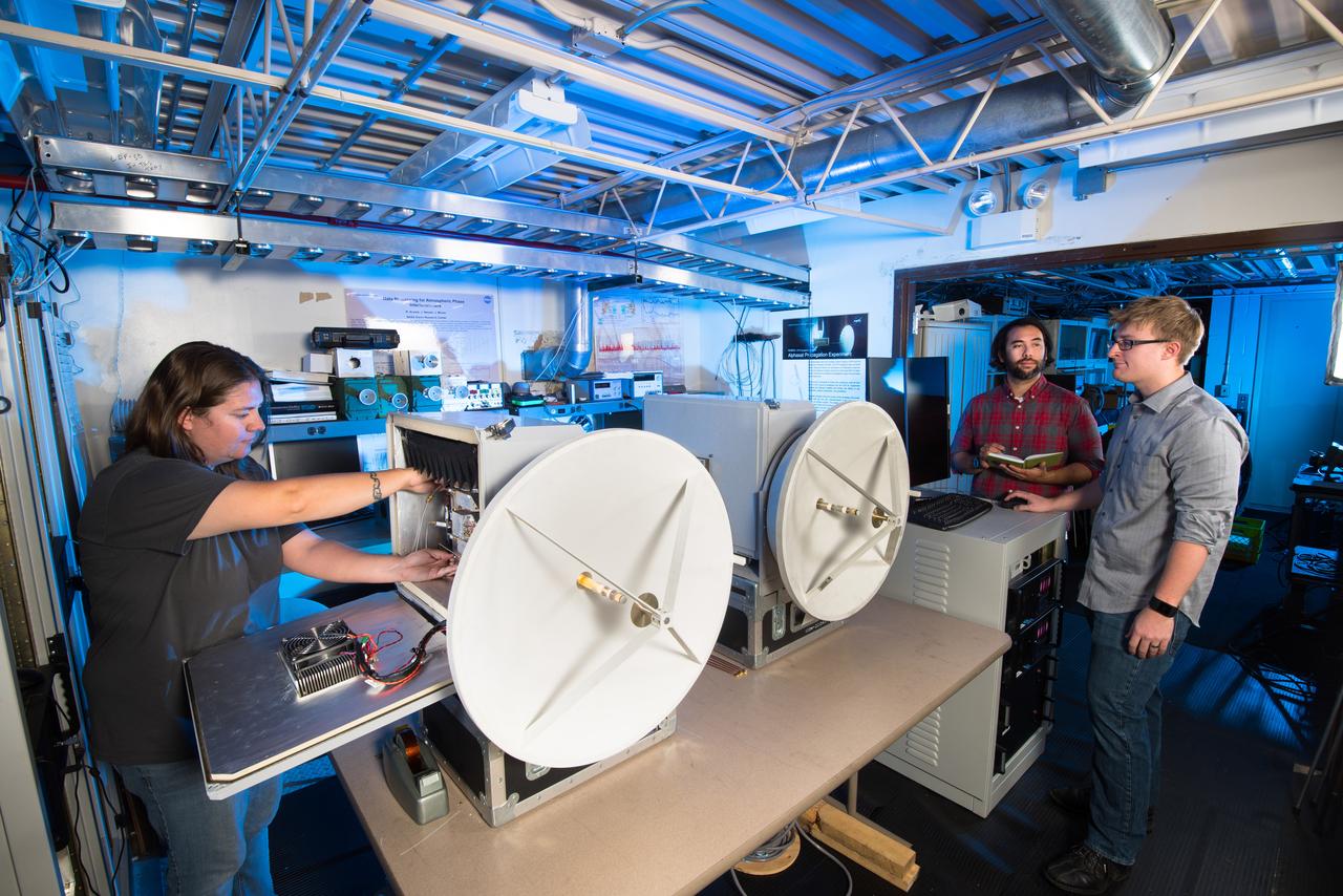
NASA Glenn researchers Jacki Houts, James Nessel and Michael Zemba perform a final inspection of the W/V-Band Terrestrial Link Experiment (WTLE) before it was transported to Albuquerque, New Mexico for testing. The experiment hardware includes a transmitter, which has been placed on the crest of the Sandia Mountains and a receiver (shown) placed at a research facility of the University of New Mexico. The wireless link spans 23km and will be used to study the effects of the atmosphere on high data-rate wireless communication links at 72 and 84 GHz. The goal of the experiment is to study these frequency bands for satellite communications.
NASA's Psyche spacecraft is shown in a clean room on June 26, 2023, at Astrotech Space Operations Facility near the agency’s Kennedy Space Center in Florida. Engineers and technicians from NASA’s Jet Propulsion Laboratory in Southern California have begun final assembly, test, and launch operations on Psyche, with assembly of the spacecraft all but complete except for the installation of the solar arrays and the imagers. NASA’s Deep Space Optical Communications (DSOC) technology demonstration, testing high-data-rate laser communications, remains integrated into the spacecraft. A final suite of tests will be run on the vehicle, after which it will be fueled and then mated onto a SpaceX Falcon Heavy rocket just prior to launch, targeted for October 2023.
KENNEDY SPACE CENTER, FLA. -- Standing in front of the U.S. Lab, named Destiny, U.S. Rep. Dave Weldon (left) thanks Thomas R. "Randy" Galloway, with the Space Station Hardware Integration Office, for briefing him on the equipment inside the Lab. Weldon is on the House Science Committee and vice chairman of the Space and Aeronautics Subcommittee. Destiny is scheduled to be launched on Space Shuttle Endeavour in early 2000. It will become the centerpiece of scientific research on the ISS, with five equipment racks aboard to provide essential functions for station systems, including high data-rate communications, and to maintain the station's orientation using control gyroscopes launched earlier. Additional equipment and research racks will be installed in the laboratory on subsequent Shuttle flights
NASA's Psyche spacecraft is shown in a clean room on June 26, 2023, at Astrotech Space Operations Facility near the agency’s Kennedy Space Center in Florida. Engineers and technicians from NASA’s Jet Propulsion Laboratory in Southern California have begun final assembly, test, and launch operations on Psyche, with assembly of the spacecraft all but complete except for the installation of the solar arrays and the imagers. NASA’s Deep Space Optical Communications (DSOC) technology demonstration, testing high-data-rate laser communications, remains integrated into the spacecraft. A final suite of tests will be run on the vehicle, after which it will be fueled and then mated onto a SpaceX Falcon Heavy rocket just prior to launch, targeted for October 2023.
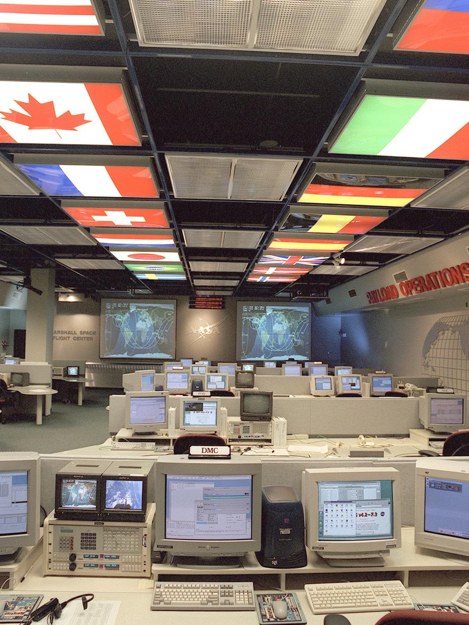
The International Space Station (ISS) Payload Operations Center (POC) at NASA's Marshall Space Flight Center (MSFC) in Huntsville, Alabama, is the world's primary science command post for the (ISS), the most ambitious space research facility in human history. The Payload Operations team is responsible for managing all science research experiments aboard the Station. The center is also home for coordination of the mission-plarning work of variety of international sources, all science payload deliveries and retrieval, and payload training and safety programs for the Station crew and all ground personnel. Within the POC, critical payload information from the ISS is displayed on a dedicated workstation, reading both S-band (low data rate) and Ku-band (high data rate) signals from a variety of experiments and procedures operated by the ISS crew and their colleagues on Earth. The POC is the focal point for incorporating research and experiment requirements from all international partners into an integrated ISS payload mission plan. This photograph is an overall view of the MSFC Payload Operations Center displaying the flags of the countries participating in the ISS. The flags at the left portray The United States, Canada, France, Switzerland, Netherlands, Japan, Brazil, and Sweden. The flags at the right portray The Russian Federation, Italy, Germany, Belgium, Spain, United Kingdom, Denmark, and Norway.
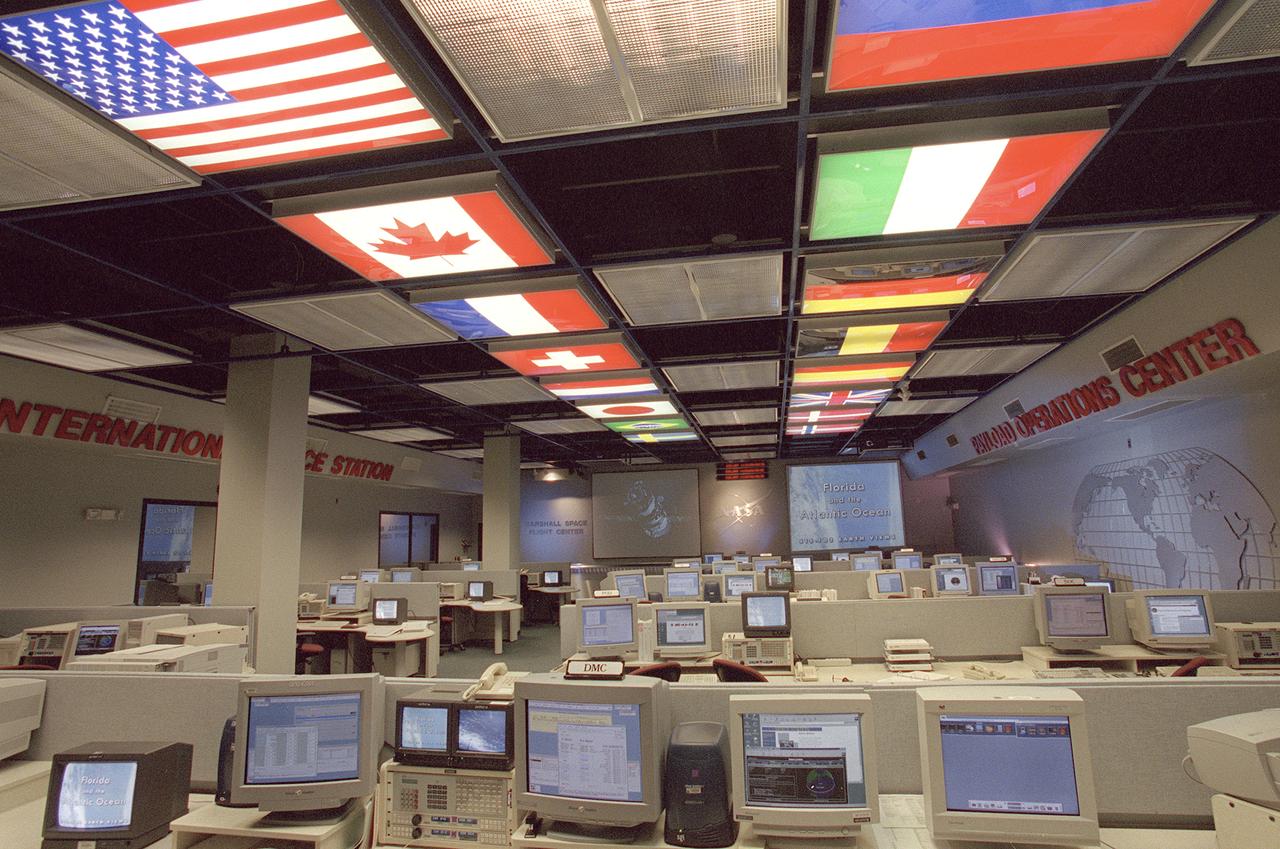
The International Space Station (ISS) Payload Operations Center (POC) at NASA's Marshall Space Flight Center (MSFC) in Huntsville, Alabama, is the world's primary science command post for the International Space Station (ISS), the most ambitious space research facility in human history. The Payload Operations team is responsible for managing all science research experiments aboard the Station. The center is also home for coordination of the mission-plarning work of variety of international sources, all science payload deliveries and retrieval, and payload training and safety programs for the Station crew and all ground personnel. Within the POC, critical payload information from the ISS is displayed on a dedicated workstation, reading both S-band (low data rate) and Ku-band (high data rate) signals from a variety of experiments and procedures operated by the ISS crew and their colleagues on Earth. The POC is the focal point for incorporating research and experiment requirements from all international partners into an integrated ISS payload mission plan. This photograph is an overall view of the MSFC Payload Operations Center displaying the flags of the countries participating the ISS. The flags at the left portray The United States, Canada, France, Switzerland, Netherlands, Japan, Brazil, and Sweden. The flags at the right portray The Russian Federation, Italy, Germany, Belgium, Spain, United Kingdom, Denmark, and Norway.
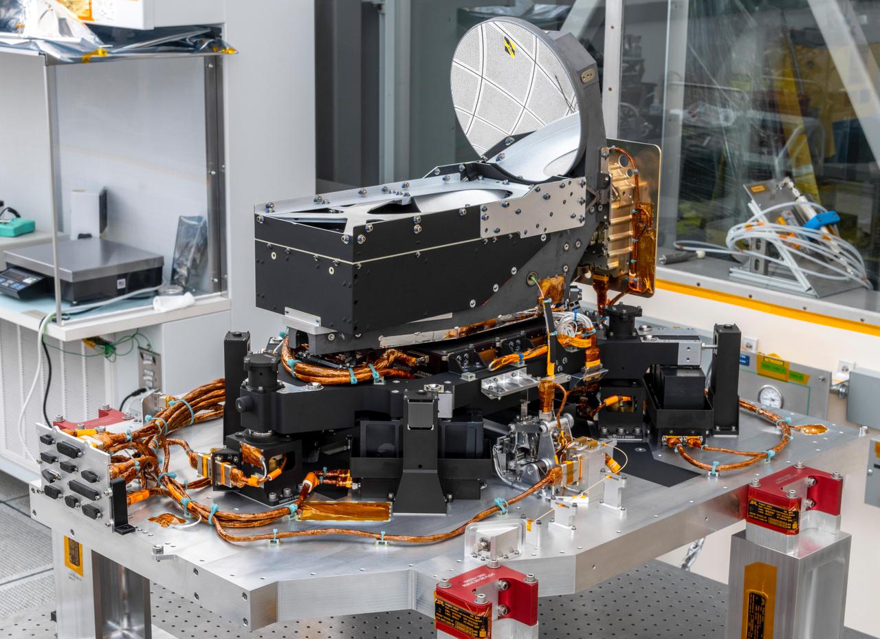
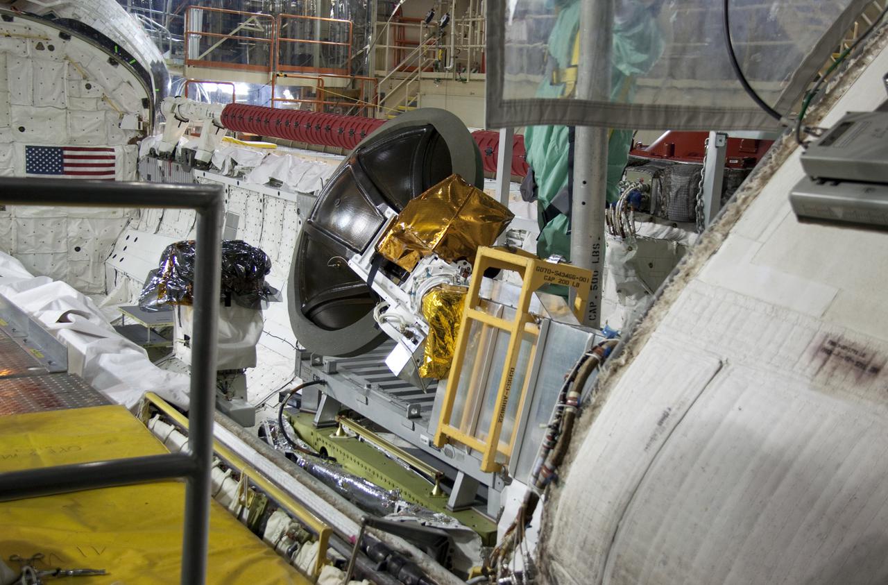
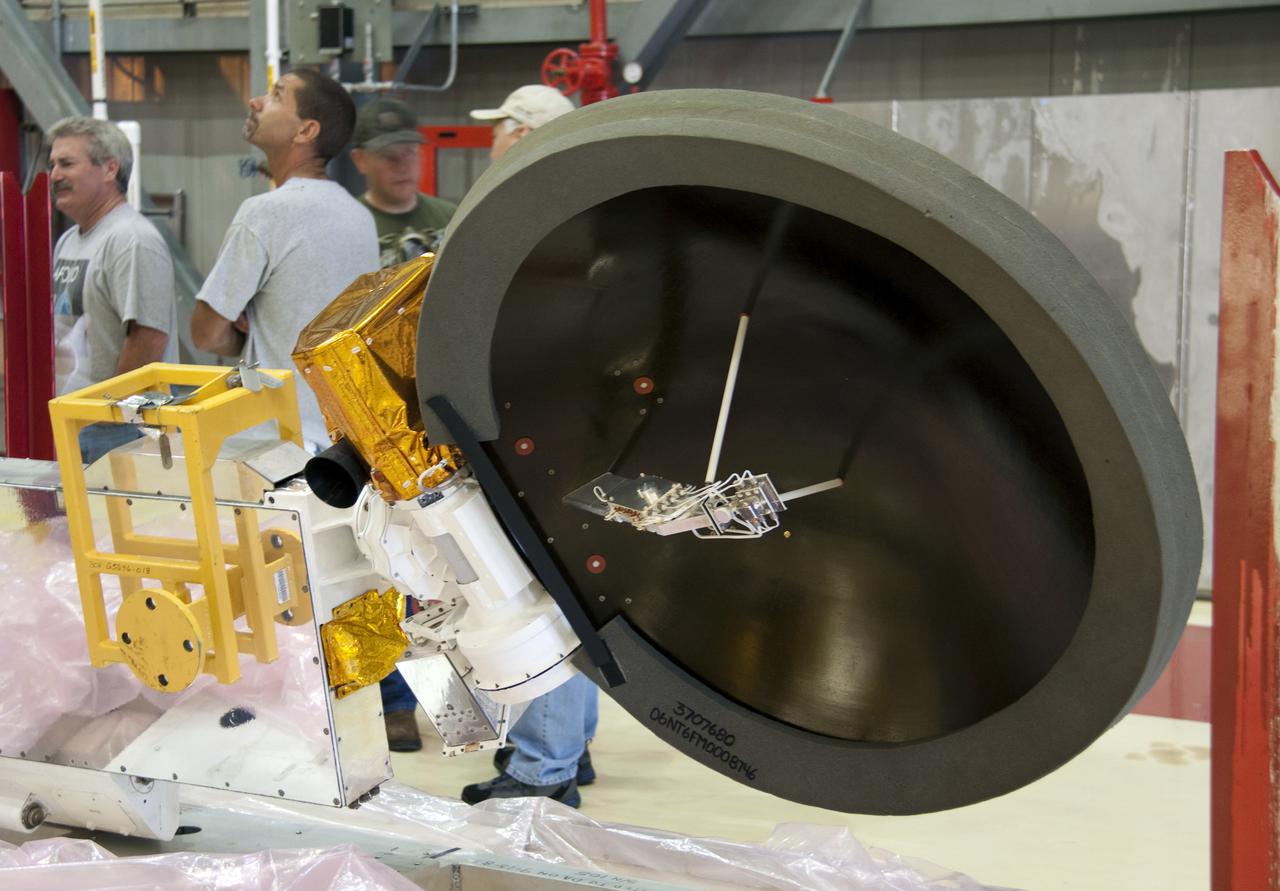
The Deep Space Optical Communications (DSOC) technology demonstration's flight laser transceiver is shown at NASA's Jet Propulsion Laboratory in Southern California in April 2021, before being installed inside its box-like enclosure that was later integrated with NASA's Psyche spacecraft. The transceiver consists of a near-infrared laser transmitter to send high-rate data to Earth, and a sensitive photon-counting camera to receive ground-transmitted low-rate data. The transceiver is mounted on an assembly of struts and actuators – shown in this photograph – that stabilizes the optics from spacecraft vibrations. The DSOC experiment is the agency's first demonstration of optical communications beyond the Earth-Moon system. DSOC is a system that consists of this flight laser transceiver, a ground laser transmitter, and a ground laser receiver. New advanced technologies have been implemented in each of these elements. The transceiver will "piggyback" on NASA's Psyche spacecraft when it launches in August 2022 to the metal-rich asteroid of the same name. The DSOC technology demonstration will begin shortly after launch and continue as the spacecraft travels from Earth to its gravity-assist flyby of Mars. https://photojournal.jpl.nasa.gov/catalog/PIA24569
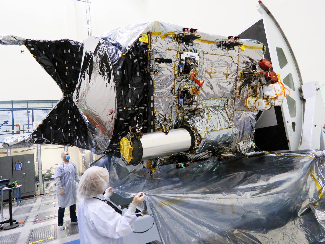
The Deep Space Optical Communications (DSOC) technology demonstration's flight laser transceiver can be easily identified on NASA's Psyche spacecraft, seen in this December 2021 photograph inside a clean room at the agency's Jet Propulsion Laboratory in Southern California. DSOC's tube-like gray/silver sunshade can be seen protruding from the side of the spacecraft. The bulge to which the sunshade is attached is DSOC's transceiver, which consists of a near-infrared laser transmitter to send high-rate data to Earth and a sensitive photon-counting camera to receive ground-transmitted low-rate data. The DSOC experiment is the agency's first demonstration of optical communications beyond the Earth-Moon system. DSOC is a system that consists of this flight laser transceiver, a ground laser transmitter, and a ground laser receiver. New advanced technologies have been implemented in each of these elements. The transceiver will "piggyback" on NASA's Psyche spacecraft when it launches in August 2022 to the metal-rich asteroid of the same name. The DSOC technology demonstration will begin shortly after launch and continue as the spacecraft travels from Earth to its gravity-assist flyby of Mars. https://photojournal.jpl.nasa.gov/catalog/PIA24570
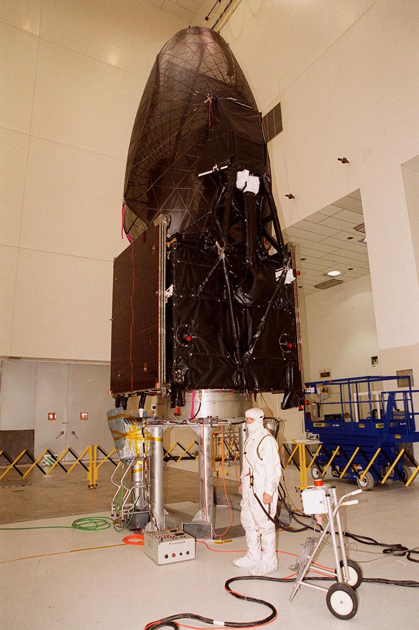
The Tracking and Data Relay Satellite (TDRS-H) sits on a workstand in KSC’s Spacecraft Assembly and Encapsulation Facility (SAEF-2) in order to undergo electrical testing. The TDRS is scheduled to be launched from CCAFS June 29 aboard an Atlas IIA/Centaur rocket. One of three satellites (labeled H, I and J) being built in the Hughes Space and Communications Company Integrated Satellite Factory in El Segundo, Calif., the latest TDRS uses an innovative springback antenna design. A pair of 15-foot-diameter, flexible mesh antenna reflectors fold up for launch, then spring back into their original cupped circular shape on orbit. The new satellites will augment the TDRS system’s existing Sand Ku-band frequencies by adding Ka-band capability. TDRS will serve as the sole means of continuous, high-data-rate communication with the space shuttle, with the International Space Station upon its completion, and with dozens of unmanned scientific satellites in low earth orbit
At Launch Pad 36A, Cape Canaveral Air Force Station, workers check out a Centaur rocket for its lift up the launch tower to be mated with the lower stage Atlas IIA rocket already in the tower. The Lockheed-built Atlas IIA/Centaur rocket will launch the latest Tracking and Data Relay Satellite (TDRS) June 29 from CCAFS. The TDRS is one of three (labeled H, I and J) being built in the Hughes Space and Communications Company Integrated Satellite Factory in El Segundo, Calif. The new satellites will augment the TDRS system’s existing Sand Ku-band frequencies by adding Ka-band capability. TDRS will serve as the sole means of continuous, high-data-rate communication with the space shuttle, with the International Space Station upon its completion, and with dozens of unmanned scientific satellites in low earth orbit

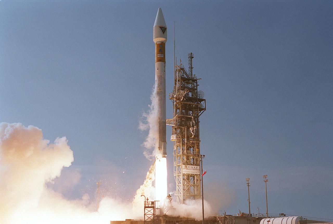
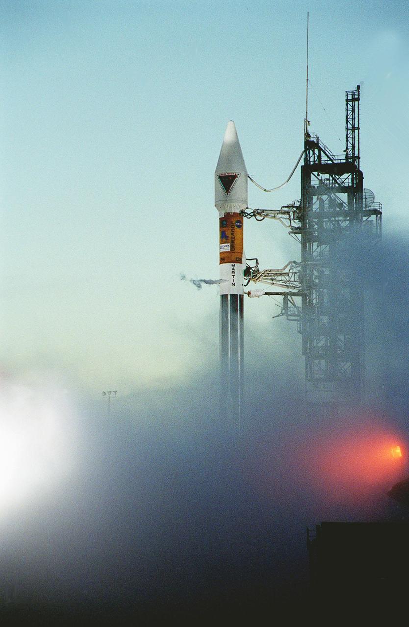
Leaving billowing clouds of steam and smoke behind, NASA’s Tracking and Data Relay Satellite (TDRS-H) shoots into the blue sky aboard an Atlas IIA/Centaur rocket from Pad 36A, Cape Canaveral Air Force Station. Liftoff occurred at 8:56 a.m. EDT. One of three satellites (labeled H, I and J) being built by the Hughes Space and Communications Company, the latest TDRS uses an innovative springback antenna design. A pair of 15-foot-diameter, flexible mesh antenna reflectors fold up for launch, then spring back into their original cupped circular shape on orbit. The new satellites will augment the TDRS system’s existing Sand Ku-band frequencies by adding Ka-band capability. TDRS will serve as the sole means of continuous, high-data-rate communication with the space shuttle, with the International Space Station upon its completion, and with dozens of unmanned scientific satellites in low earth orbit
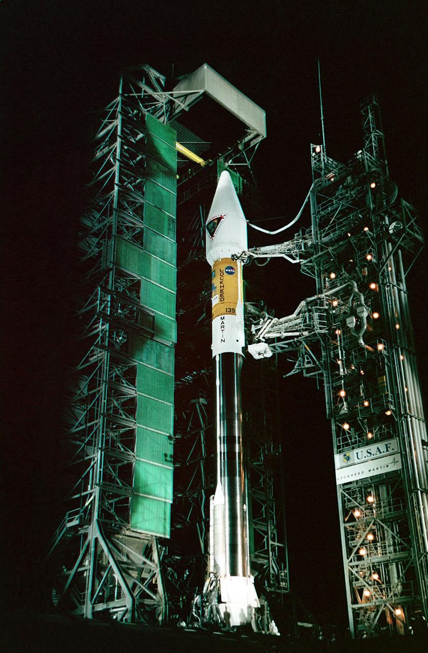
In the early morning hours on Launch Pad 36A, Cape Canaveral Air Force Station, the tower rolls back from NASA’s Tracking and Data Relay Satellite (TDRS-H) before liftoff atop an Atlas IIA/Centaur rocket. One of three satellites (labeled H, I and J) being built by the Hughes Space and Communications Company, the latest TDRS uses an innovative springback antenna design. A pair of 15-foot-diameter, flexible mesh antenna reflectors fold up for launch, then spring back into their original cupped circular shape on orbit. The new satellites will augment the TDRS system’s existing Sand Ku-band frequencies by adding Ka-band capability. TDRS will serve as the sole means of continuous, high-data-rate communication with the Space Shuttle, with the International Space Station upon its completion, and with dozens of unmanned scientific satellites in low earth orbit

At Launch Pad 36A, Cape Canaveral Air Force Station, a Centaur rocket arrives for mating with the Atlas IIA rocket already in the tower. The Centaur upper stage is 10.0 m (33-ft) long and 3.05 m (10 ft) in diameter. The Lockheed-built Atlas IIA/Centaur rocket will launch the latest Tracking and Data Relay Satellite (TDRS) June 29 from CCAFS. The TDRS is one of three (labeled H, I and J) being built in the Hughes Space and Communications Company Integrated Satellite Factory in El Segundo, Calif. The new satellites will augment the TDRS system’s existing Sand Ku-band frequencies by adding Ka-band capability. TDRS will serve as the sole means of continuous, high-data-rate communication with the space shuttle, with the International Space Station upon its completion, and with dozens of unmanned scientific satellites in low earth orbit
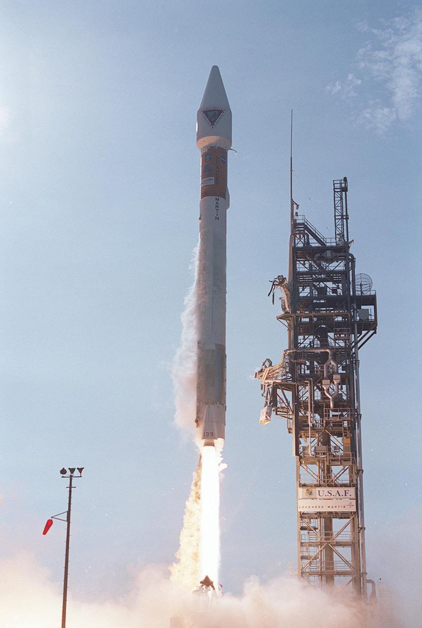
Looking like a Roman candle, NASA’s Tracking and Data Relay Satellite (TDRS-H) shoots into the blue sky aboard an Atlas IIA/Centaur rocket from Pad 36A, Cape Canaveral Air Force Station. Liftoff occurred at 8:56 a.m. EDT. One of three satellites (labeled H, I and J) being built by the Hughes Space and Communications Company, the latest TDRS uses an innovative springback antenna design. A pair of 15-foot-diameter, flexible mesh antenna reflectors fold up for launch, then spring back into their original cupped circular shape on orbit. The new satellites will augment the TDRS system’s existing Sand Ku-band frequencies by adding Ka-band capability. TDRS will serve as the sole means of continuous, high-data-rate communication with the space shuttle, with the International Space Station upon its completion, and with dozens of unmanned scientific satellites in low earth orbit
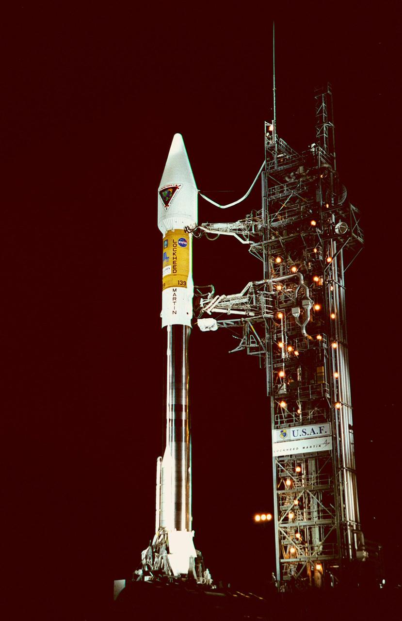
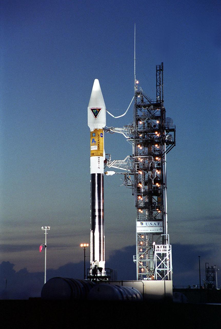
In the early morning hours, NASA’s Tracking and Data Relay Satellite (TDRS-H) sits poised on Launch Pad 36A, Cape Canaveral Air Force Station, before its scheduled launch aboard an Atlas IIA/Centaur rocket. One of three satellites (labeled H, I and J) being built by the Hughes Space and Communications Company, the latest TDRS uses an innovative springback antenna design. A pair of 15-foot-diameter, flexible mesh antenna reflectors fold up for launch, then spring back into their original cupped circular shape on orbit. The new satellites will augment the TDRS system’s existing Sand Ku-band frequencies by adding Ka-band capability. TDRS will serve as the sole means of continuous, high-data-rate communication with the Space Shuttle, with the International Space Station upon its completion, and with dozens of unmanned scientific satellites in low earth orbit
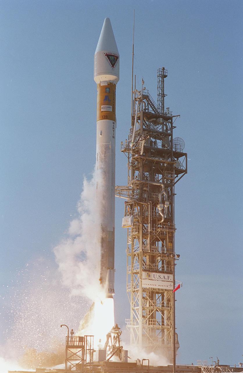
NASA’s Tracking and Data Relay Satellite (TDRS-H) rises into the blue sky from Pad 36A, Cape Canaveral Air Force Station. Liftoff occurred at 8:56 a.m. EDT aboard an Atlas IIA/Centaur rocket. One of three satellites (labeled H, I and J) being built by the Hughes Space and Communications Company, the latest TDRS uses an innovative springback antenna design. A pair of 15-foot-diameter, flexible mesh antenna reflectors fold up for launch, then spring back into their original cupped circular shape on orbit. The new satellites will augment the TDRS system’s existing Sand Ku-band frequencies by adding Ka-band capability. TDRS will serve as the sole means of continuous, high-data-rate communication with the space shuttle, with the International Space Station upon its completion, and with dozens of unmanned scientific satellites in low earth orbit

Workers in KSC’s Spacecraft Assembly and Encapsulation Facility (SAEF-2) prepare the Tracking and Data Relay Satellite (TDRS-H) above them for electrical testing. The TDRS is scheduled to be launched from CCAFS June 29 aboard an Atlas IIA/Centaur rocket. One of three satellites (labeled H, I and J) being built in the Hughes Space and Communications Company Integrated Satellite Factory in El Segundo, Calif., the latest TDRS uses an innovative springback antenna design. A pair of 15-foot-diameter, flexible mesh antenna reflectors fold up for launch, then spring back into their original cupped circular shape on orbit. The new satellites will augment the TDRS system’s existing Sand Ku-band frequencies by adding Ka-band capability. TDRS will serve as the sole means of continuous, high-data-rate communication with the space shuttle, with the International Space Station upon its completion, and with dozens of unmanned scientific satellites in low earth orbit

At Launch Pad 36A, Cape Canaveral Air Force Station, workers guide the ascent of a Centaur rocket up the launch tower where it will be mated with the lower stage Atlas IIA rocket already in the tower. The Lockheed-built Atlas IIA/Centaur rocket will launch the latest Tracking and Data Relay Satellite (TDRS) June 29 from CCAFS. The TDRS is one of three (labeled H, I and J) being built in the Hughes Space and Communications Company Integrated Satellite Factory in El Segundo, Calif. The new satellites will augment the TDRS system’s existing Sand Ku-band frequencies by adding Ka-band capability. TDRS will serve as the sole means of continuous, high-data-rate communication with the space shuttle, with the International Space Station upon its completion, and with dozens of unmanned scientific satellites in low earth orbit

In the early morning hours on Launch Pad 36A, Cape Canaveral Air Force Station, the tower rolls back from NASA’s Tracking and Data Relay Satellite (TDRS-H) before liftoff atop an Atlas IIA/Centaur rocket. One of three satellites (labeled H, I and J) being built by the Hughes Space and Communications Company, the latest TDRS uses an innovative springback antenna design. A pair of 15-foot-diameter, flexible mesh antenna reflectors fold up for launch, then spring back into their original cupped circular shape on orbit. The new satellites will augment the TDRS system’s existing Sand Ku-band frequencies by adding Ka-band capability. TDRS will serve as the sole means of continuous, high-data-rate communication with the Space Shuttle, with the International Space Station upon its completion, and with dozens of unmanned scientific satellites in low earth orbit

NASA’s Tracking and Data Relay Satellite (TDRS-H) sits poised on Launch Pad 36A, Cape Canaveral Air Force Station, before its scheduled launch aboard an Atlas IIA/Centaur rocket. One of three satellites (labeled H, I and J) being built by the Hughes Space and Communications Company, the latest TDRS uses an innovative springback antenna design. A pair of 15-foot-diameter, flexible mesh antenna reflectors fold up for launch, then spring back into their original cupped circular shape on orbit. The new satellites will augment the TDRS system’s existing Sand Ku-band frequencies by adding Ka-band capability. TDRS will serve as the sole means of continuous, high-data-rate communication with the space shuttle, with the International Space Station upon its completion, and with dozens of unmanned scientific satellites in low earth orbit

At dawn on Launch Pad 36A, Cape Canaveral Air Force Station, an Atlas IIA/Centaur rocket is fueled for launch of NASA’s Tracking and Data Relay Satellite (TDRS-H). One of three satellites (labeled H, I and J) being built by the Hughes Space and Communications Company, the latest TDRS uses an innovative springback antenna design. A pair of 15-foot-diameter, flexible mesh antenna reflectors fold up for launch, then spring back into their original cupped circular shape on orbit. The new satellites will augment the TDRS system’s existing Sand Ku-band frequencies by adding Ka-band capability. TDRS will serve as the sole means of continuous, high-data-rate communication with the Space Shuttle, with the International Space Station upon its completion, and with dozens of unmanned scientific satellites in low earth orbit
In this long view of the launch tower at Pad 36A, Cape Canaveral Air Force Station, the upper stage Centaur rocket can be seen as it rises up the tower to be mated to the lower stage Atlas IIA rocket already there. The Lockheed-built Atlas IIA/Centaur rocket will launch the latest Tracking and Data Relay Satellite (TDRS) June 29 from CCAFS. The TDRS is one of three (labeled H, I and J) being built in the Hughes Space and Communications Company Integrated Satellite Factory in El Segundo, Calif. The new satellites will augment the TDRS system’s existing Sand Ku-band frequencies by adding Ka-band capability. TDRS will serve as the sole means of continuous, high-data-rate communication with the space shuttle, with the International Space Station upon its completion, and with dozens of unmanned scientific satellites in low earth orbit

Looking like a Roman candle, NASA’s Tracking and Data Relay Satellite (TDRS-H) shoots into the blue sky aboard an Atlas IIA/Centaur rocket from Pad 36A, Cape Canaveral Air Force Station. Liftoff occurred at 8:56 a.m. EDT. One of three satellites (labeled H, I and J) being built by the Hughes Space and Communications Company, the latest TDRS uses an innovative springback antenna design. A pair of 15-foot-diameter, flexible mesh antenna reflectors fold up for launch, then spring back into their original cupped circular shape on orbit. The new satellites will augment the TDRS system’s existing Sand Ku-band frequencies by adding Ka-band capability. TDRS will serve as the sole means of continuous, high-data-rate communication with the space shuttle, with the International Space Station upon its completion, and with dozens of unmanned scientific satellites in low earth orbit
At Launch Pad 36A, Cape Canaveral Air Force Station, a Centaur rocket arrives for mating with the Atlas IIA rocket already in the tower. The Centaur upper stage is 10.0 m (33-ft) long and 3.05 m (10 ft) in diameter. The Lockheed-built Atlas IIA/Centaur rocket will launch the latest Tracking and Data Relay Satellite (TDRS) June 29 from CCAFS. The TDRS is one of three (labeled H, I and J) being built in the Hughes Space and Communications Company Integrated Satellite Factory in El Segundo, Calif. The new satellites will augment the TDRS system’s existing Sand Ku-band frequencies by adding Ka-band capability. TDRS will serve as the sole means of continuous, high-data-rate communication with the space shuttle, with the International Space Station upon its completion, and with dozens of unmanned scientific satellites in low earth orbit

The Tracking and Data Relay Satellite (TDRS-H) sits on a workstand in KSC’s Spacecraft Assembly and Encapsulation Facility (SAEF-2) in order to undergo electrical testing. The TDRS is scheduled to be launched from CCAFS June 29 aboard an Atlas IIA/Centaur rocket. One of three satellites (labeled H, I and J) being built in the Hughes Space and Communications Company Integrated Satellite Factory in El Segundo, Calif., the latest TDRS uses an innovative springback antenna design. A pair of 15-foot-diameter, flexible mesh antenna reflectors fold up for launch, then spring back into their original cupped circular shape on orbit. The new satellites will augment the TDRS system’s existing Sand Ku-band frequencies by adding Ka-band capability. TDRS will serve as the sole means of continuous, high-data-rate communication with the space shuttle, with the International Space Station upon its completion, and with dozens of unmanned scientific satellites in low earth orbit
NASA’s Tracking and Data Relay Satellite (TDRS-H) sits poised on Launch Pad 36A, Cape Canaveral Air Force Station, before its scheduled launch aboard an Atlas IIA/Centaur rocket. One of three satellites (labeled H, I and J) being built by the Hughes Space and Communications Company, the latest TDRS uses an innovative springback antenna design. A pair of 15-foot-diameter, flexible mesh antenna reflectors fold up for launch, then spring back into their original cupped circular shape on orbit. The new satellites will augment the TDRS system’s existing Sand Ku-band frequencies by adding Ka-band capability. TDRS will serve as the sole means of continuous, high-data-rate communication with the space shuttle, with the International Space Station upon its completion, and with dozens of unmanned scientific satellites in low earth orbit
Workers in KSC’s Spacecraft Assembly and Encapsulation Facility (SAEF-2) conduct electrical testing on the Tracking and Data Relay Satellite (TDRS-H) above them. The TDRS is scheduled to be launched from CCAFS June 29 aboard an Atlas IIA/Centaur rocket. One of three satellites (labeled H, I and J) being built in the Hughes Space and Communications Company Integrated Satellite Factory in El Segundo, Calif., the latest TDRS uses an innovative springback antenna design. A pair of 15-foot-diameter, flexible mesh antenna reflectors fold up for launch, then spring back into their original cupped circular shape on orbit. The new satellites will augment the TDRS system’s existing Sand Ku-band frequencies by adding Ka-band capability. TDRS will serve as the sole means of continuous, high-data-rate communication with the space shuttle, with the International Space Station upon its completion, and with dozens of unmanned scientific satellites in low earth orbit
At Launch Pad 36A, Cape Canaveral Air Force Station, workers guide the ascent of a Centaur rocket up the launch tower where it will be mated with the lower stage Atlas IIA rocket already in the tower. The Lockheed-built Atlas IIA/Centaur rocket will launch the latest Tracking and Data Relay Satellite (TDRS) June 29 from CCAFS. The TDRS is one of three (labeled H, I and J) being built in the Hughes Space and Communications Company Integrated Satellite Factory in El Segundo, Calif. The new satellites will augment the TDRS system’s existing Sand Ku-band frequencies by adding Ka-band capability. TDRS will serve as the sole means of continuous, high-data-rate communication with the space shuttle, with the International Space Station upon its completion, and with dozens of unmanned scientific satellites in low earth orbit

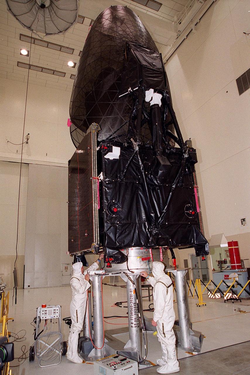
The Tracking and Data Relay Satellite (TDRS-H) sits fully encapsulated inside the fairing. Next, it will be transported to Launch Pad 36A, Cape Canaveral Air Force Station for launch scheduled June 29 aboard an Atlas IIA/Centaur rocket. One of three satellites (labeled H, I and J) being built in the Hughes Space and Communications Company Integrated Satellite Factory in El Segundo, Calif., the latest TDRS uses an innovative springback antenna design. A pair of 15-foot-diameter, flexible mesh antenna reflectors fold up for launch, then spring back into their original cupped circular shape on orbit. The new satellites will augment the TDRS system’s existing Sand Ku-band frequencies by adding Ka-band capability. TDRS will serve as the sole means of continuous, high-data-rate communication with the space shuttle, with the International Space Station upon its completion, and with dozens of unmanned scientific satellites in low earth orbit

After tower rollback just before dawn on Launch Pad 36A, Cape Canaveral Air Force Station, NASA’s Tracking and Data Relay Satellite (TDRS-H) sits bathed in spotlights before liftoff atop an Atlas IIA/Centaur rocket. One of three satellites (labeled H, I and J) being built by the Hughes Space and Communications Company, the latest TDRS uses an innovative springback antenna design. A pair of 15-foot-diameter, flexible mesh antenna reflectors fold up for launch, then spring back into their original cupped circular shape on orbit. The new satellites will augment the TDRS system’s existing Sand Ku-band frequencies by adding Ka-band capability. TDRS will serve as the sole means of continuous, high-data-rate communication with the Space Shuttle, with the International Space Station upon its completion, and with dozens of unmanned scientific satellites in low earth orbit
Leaving billowing clouds of steam and smoke behind, NASA’s Tracking and Data Relay Satellite (TDRS-H) shoots into the blue sky aboard an Atlas IIA/Centaur rocket from Pad 36A, Cape Canaveral Air Force Station. Liftoff occurred at 8:56 a.m. EDT. One of three satellites (labeled H, I and J) being built by the Hughes Space and Communications Company, the latest TDRS uses an innovative springback antenna design. A pair of 15-foot-diameter, flexible mesh antenna reflectors fold up for launch, then spring back into their original cupped circular shape on orbit. The new satellites will augment the TDRS system’s existing Sand Ku-band frequencies by adding Ka-band capability. TDRS will serve as the sole means of continuous, high-data-rate communication with the space shuttle, with the International Space Station upon its completion, and with dozens of unmanned scientific satellites in low earth orbit
After tower rollback just before dawn on Launch Pad 36A, Cape Canaveral Air Force Station, NASA’s Tracking and Data Relay Satellite (TDRS-H) sits bathed in spotlights before liftoff atop an Atlas IIA/Centaur rocket. One of three satellites (labeled H, I and J) being built by the Hughes Space and Communications Company, the latest TDRS uses an innovative springback antenna design. A pair of 15-foot-diameter, flexible mesh antenna reflectors fold up for launch, then spring back into their original cupped circular shape on orbit. The new satellites will augment the TDRS system’s existing Sand Ku-band frequencies by adding Ka-band capability. TDRS will serve as the sole means of continuous, high-data-rate communication with the Space Shuttle, with the International Space Station upon its completion, and with dozens of unmanned scientific satellites in low earth orbit
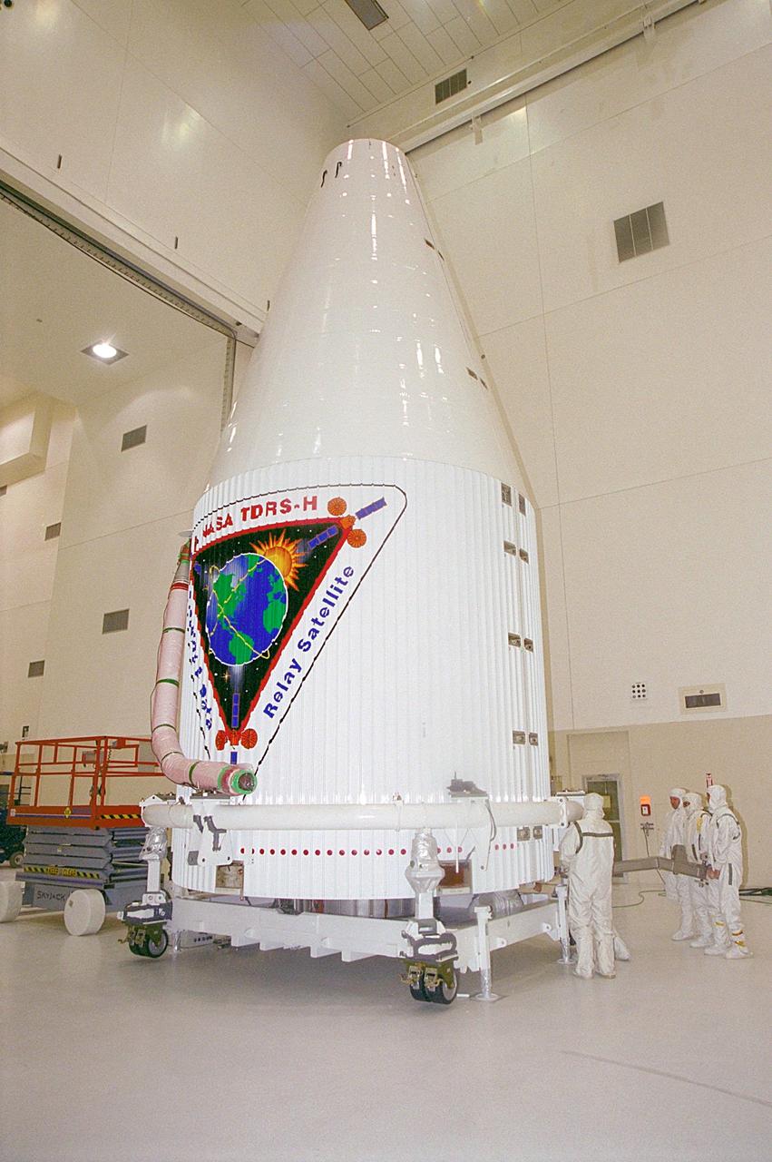
The Tracking and Data Relay Satellite (TDRS-H) sits fully encapsulated inside the fairing. Next, it will be transported to Launch Pad 36A, Cape Canaveral Air Force Station for launch scheduled June 29 aboard an Atlas IIA/Centaur rocket. One of three satellites (labeled H, I and J) being built in the Hughes Space and Communications Company Integrated Satellite Factory in El Segundo, Calif., the latest TDRS uses an innovative springback antenna design. A pair of 15-foot-diameter, flexible mesh antenna reflectors fold up for launch, then spring back into their original cupped circular shape on orbit. The new satellites will augment the TDRS system’s existing Sand Ku-band frequencies by adding Ka-band capability. TDRS will serve as the sole means of continuous, high-data-rate communication with the space shuttle, with the International Space Station upon its completion, and with dozens of unmanned scientific satellites in low earth orbit
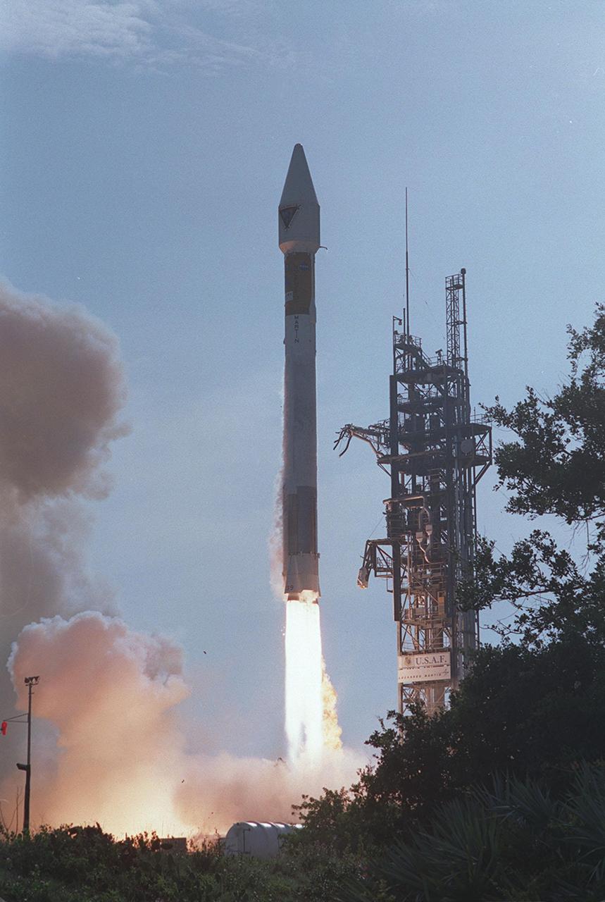
NASA’s Tracking and Data Relay Satellite (TDRS-H) rises into the blue sky from Pad 36A, Cape Canaveral Air Force Station. Liftoff occurred at 8:56 a.m. EDT aboard an Atlas IIA/Centaur rocket. One of three satellites (labeled H, I and J) being built by the Hughes Space and Communications Company, the latest TDRS uses an innovative springback antenna design. A pair of 15-foot-diameter, flexible mesh antenna reflectors fold up for launch, then spring back into their original cupped circular shape on orbit. The new satellites will augment the TDRS system’s existing Sand Ku-band frequencies by adding Ka-band capability. TDRS will serve as the sole means of continuous, high-data-rate communication with the space shuttle, with the International Space Station upon its completion, and with dozens of unmanned scientific satellites in low earth orbit

At Launch Pad 36A, Cape Canaveral Air Force Station, a Centaur rocket is raised to a vertical position before lifting it up the launch tower. It will be mated with the lower stage Atlas IIA rocket, already in the tower, to launch the latest Tracking and Data Relay Satellite (TDRS) June 29 from CCAFS. The TDRS is one of three (labeled H, I and J) being built in the Hughes Space and Communications Company Integrated Satellite Factory in El Segundo, Calif. The new satellites will augment the TDRS system’s existing Sand Ku-band frequencies by adding Ka-band capability. TDRS will serve as the sole means of continuous, high-data-rate communication with the space shuttle, with the International Space Station upon its completion, and with dozens of unmanned scientific satellites in low earth orbit

In this long view of the launch tower at Pad 36A, Cape Canaveral Air Force Station, the upper stage Centaur rocket can be seen as it rises up the tower to be mated to the lower stage Atlas IIA rocket already there. The Lockheed-built Atlas IIA/Centaur rocket will launch the latest Tracking and Data Relay Satellite (TDRS) June 29 from CCAFS. The TDRS is one of three (labeled H, I and J) being built in the Hughes Space and Communications Company Integrated Satellite Factory in El Segundo, Calif. The new satellites will augment the TDRS system’s existing Sand Ku-band frequencies by adding Ka-band capability. TDRS will serve as the sole means of continuous, high-data-rate communication with the space shuttle, with the International Space Station upon its completion, and with dozens of unmanned scientific satellites in low earth orbit

At Launch Pad 36A, Cape Canaveral Air Force Station, workers check out a Centaur rocket for its lift up the launch tower to be mated with the lower stage Atlas IIA rocket already in the tower. The Lockheed-built Atlas IIA/Centaur rocket will launch the latest Tracking and Data Relay Satellite (TDRS) June 29 from CCAFS. The TDRS is one of three (labeled H, I and J) being built in the Hughes Space and Communications Company Integrated Satellite Factory in El Segundo, Calif. The new satellites will augment the TDRS system’s existing Sand Ku-band frequencies by adding Ka-band capability. TDRS will serve as the sole means of continuous, high-data-rate communication with the space shuttle, with the International Space Station upon its completion, and with dozens of unmanned scientific satellites in low earth orbit
At dawn on Launch Pad 36A, Cape Canaveral Air Force Station, an Atlas IIA/Centaur rocket is fueled for launch of NASA’s Tracking and Data Relay Satellite (TDRS-H). One of three satellites (labeled H, I and J) being built by the Hughes Space and Communications Company, the latest TDRS uses an innovative springback antenna design. A pair of 15-foot-diameter, flexible mesh antenna reflectors fold up for launch, then spring back into their original cupped circular shape on orbit. The new satellites will augment the TDRS system’s existing Sand Ku-band frequencies by adding Ka-band capability. TDRS will serve as the sole means of continuous, high-data-rate communication with the Space Shuttle, with the International Space Station upon its completion, and with dozens of unmanned scientific satellites in low earth orbit
At Launch Pad 36A, Cape Canaveral Air Force Station, a Centaur rocket is raised to a vertical position before lifting it up the launch tower. It will be mated with the lower stage Atlas IIA rocket, already in the tower, to launch the latest Tracking and Data Relay Satellite (TDRS) June 29 from CCAFS. The TDRS is one of three (labeled H, I and J) being built in the Hughes Space and Communications Company Integrated Satellite Factory in El Segundo, Calif. The new satellites will augment the TDRS system’s existing Sand Ku-band frequencies by adding Ka-band capability. TDRS will serve as the sole means of continuous, high-data-rate communication with the space shuttle, with the International Space Station upon its completion, and with dozens of unmanned scientific satellites in low earth orbit

NASA’s Tracking and Data Relay Satellite (TDRS-H) rises into the blue sky from Pad 36A, Cape Canaveral Air Force Station. Liftoff occurred at 8:56 a.m. EDT aboard an Atlas IIA/Centaur rocket. One of three satellites (labeled H, I and J) being built by the Hughes Space and Communications Company, the latest TDRS uses an innovative springback antenna design. A pair of 15-foot-diameter, flexible mesh antenna reflectors fold up for launch, then spring back into their original cupped circular shape on orbit. The new satellites will augment the TDRS system’s existing Sand Ku-band frequencies by adding Ka-band capability. TDRS will serve as the sole means of continuous, high-data-rate communication with the space shuttle, with the International Space Station upon its completion, and with dozens of unmanned scientific satellites in low earth orbit

NASA’s Tracking and Data Relay Satellite (TDRS-H) rises into the blue sky from Pad 36A, Cape Canaveral Air Force Station. Liftoff occurred at 8:56 a.m. EDT aboard an Atlas IIA/Centaur rocket. One of three satellites (labeled H, I and J) being built by the Hughes Space and Communications Company, the latest TDRS uses an innovative springback antenna design. A pair of 15-foot-diameter, flexible mesh antenna reflectors fold up for launch, then spring back into their original cupped circular shape on orbit. The new satellites will augment the TDRS system’s existing Sand Ku-band frequencies by adding Ka-band capability. TDRS will serve as the sole means of continuous, high-data-rate communication with the space shuttle, with the International Space Station upon its completion, and with dozens of unmanned scientific satellites in low earth orbit
At Launch Pad 36A, Cape Canaveral Air Force Station, lines help guide the ascent of a Centaur rocket up the launch tower where it will be mated with the lower stage Atlas IIA rocket already in the tower. The Lockheed-built Atlas IIA/Centaur rocket will launch the latest Tracking and Data Relay Satellite (TDRS) June 29 from CCAFS. The TDRS is one of three (labeled H, I and J) being built in the Hughes Space and Communications Company Integrated Satellite Factory in El Segundo, Calif. The new satellites will augment the TDRS system’s existing Sand Ku-band frequencies by adding Ka-band capability. TDRS will serve as the sole means of continuous, high-data-rate communication with the space shuttle, with the International Space Station upon its completion, and with dozens of unmanned scientific satellites in low earth orbit

In the early morning hours, NASA’s Tracking and Data Relay Satellite (TDRS-H) sits poised on Launch Pad 36A, Cape Canaveral Air Force Station, before its scheduled launch aboard an Atlas IIA/Centaur rocket. One of three satellites (labeled H, I and J) being built by the Hughes Space and Communications Company, the latest TDRS uses an innovative springback antenna design. A pair of 15-foot-diameter, flexible mesh antenna reflectors fold up for launch, then spring back into their original cupped circular shape on orbit. The new satellites will augment the TDRS system’s existing Sand Ku-band frequencies by adding Ka-band capability. TDRS will serve as the sole means of continuous, high-data-rate communication with the Space Shuttle, with the International Space Station upon its completion, and with dozens of unmanned scientific satellites in low earth orbit
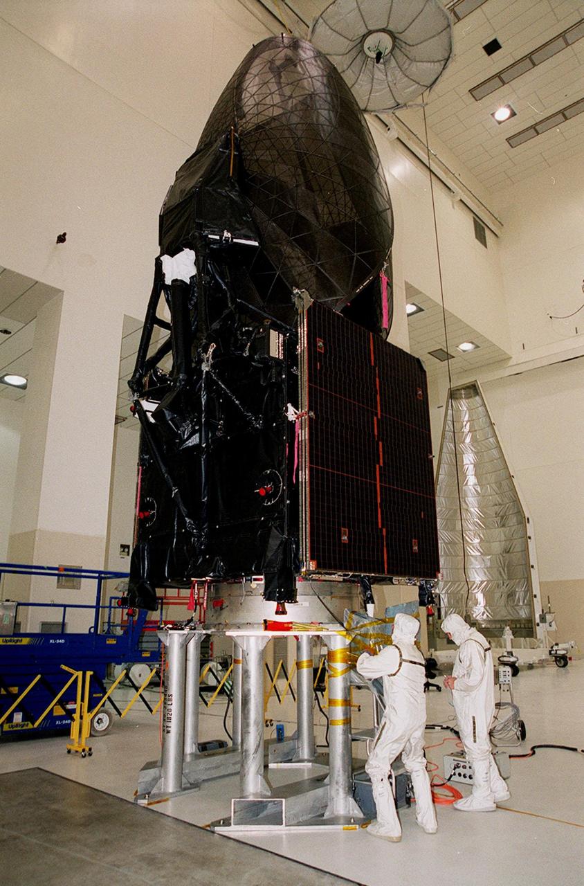
Workers in KSC’s Spacecraft Assembly and Encapsulation Facility (SAEF-2) prepare the Tracking and Data Relay Satellite (TDRS-H) above them for electrical testing. The TDRS is scheduled to be launched from CCAFS June 29 aboard an Atlas IIA/Centaur rocket. One of three satellites (labeled H, I and J) being built in the Hughes Space and Communications Company Integrated Satellite Factory in El Segundo, Calif., the latest TDRS uses an innovative springback antenna design. A pair of 15-foot-diameter, flexible mesh antenna reflectors fold up for launch, then spring back into their original cupped circular shape on orbit. The new satellites will augment the TDRS system’s existing Sand Ku-band frequencies by adding Ka-band capability. TDRS will serve as the sole means of continuous, high-data-rate communication with the space shuttle, with the International Space Station upon its completion, and with dozens of unmanned scientific satellites in low earth orbit

At Launch Pad 36A, Cape Canaveral Air Force Station, lines help guide the ascent of a Centaur rocket up the launch tower where it will be mated with the lower stage Atlas IIA rocket already in the tower. The Lockheed-built Atlas IIA/Centaur rocket will launch the latest Tracking and Data Relay Satellite (TDRS) June 29 from CCAFS. The TDRS is one of three (labeled H, I and J) being built in the Hughes Space and Communications Company Integrated Satellite Factory in El Segundo, Calif. The new satellites will augment the TDRS system’s existing Sand Ku-band frequencies by adding Ka-band capability. TDRS will serve as the sole means of continuous, high-data-rate communication with the space shuttle, with the International Space Station upon its completion, and with dozens of unmanned scientific satellites in low earth orbit
Shown here is a prototype of the Deep Space Optical Communications, or DSOC, ground receiver detector built by the Microdevices Laboratory at NASA's Jet Propulsion Laboratory in Southern California. The prototype superconducting nanowire single-photon detector was used by JPL technologists to help develop the detector that – from a station on Earth – will receive near-infrared laser signals from the DSOC flight transceiver traveling with NASA's Psyche mission in deep space. DSOC will test key technologies that could enable high-bandwidth optical, or laser, communications from Mars distances. Bolted to the side of the spacecraft and operating for the first two years of Psyche's journey to the asteroid of the same name, the DSOC flight laser transceiver will transmit high-rate data to Caltech's Palomar Observatory in San Diego County, California, which houses the 200-inch (5.1-meter) Hale Telescope. The downlink detector converts optical signals to electrical signals, which can be processed and decoded. The detector is designed to be both sensitive enough to detect single photons (quantum particles of light) and able to detect many photons arriving all at once. At its farthest point during the technology demonstration's operations period, the transceiver will be up to 240 million miles (390 million kilometers) away, meaning that by the time its weak laser pulses arrive at Earth, the detector will need to efficiently detect a trickle of single photons. But when the spacecraft is closer to Earth and the flight transceiver is delivering its highest bit rate to Palomar, the detector is capable of detecting very high numbers of photons without becoming overwhelmed. Because data is encoded in the timing of the laser pulses, the detector must also be able to determine the time of a photon's arrival with a precision of 100 picoseconds (one picosecond is one trillionth of a second). DSOC is the latest in a series of optical communication technology demonstrations funded by NASA's Technology Demonstrations Missions (TDM) program and the agency's Space Communications and Navigation (SCaN) program. JPL, a division of Caltech in Pasadena, California, manages DSOC for TDM within NASA's Space Technology Mission Directorate and SCaN within the agency's Space Operations Mission Directorate. https://photojournal.jpl.nasa.gov/catalog/PIA25840
KENNEDY SPACE CENTER, FLA. - At Astrotech Space Operations in Titusville, Fla., the two STEREO spacecraft are being prepared for installation of the solar arrays. In the foreground is spacecraft "B," sitting as it would on the rocket. Pointing to the right is the high gain antenna (HGA), which is used to get science data at high data rates back to Earth. In the background is the "A" observatory, rotated horizontally on a Ransome table so that its HGA is pointing upward. The black circle facing forward is the primary instrument Sun Earth Connection Coronal and Heliospheric Investigation (SECCHI), a suite of remote sensing instruments to image solar flares, with a protective cover that is removed before flight. STEREO consists of two spacecraft whose mission is the first to take measurements of the sun and solar wind in 3-D. This new view will improve our understanding of space weather and its impact on the Earth. Preparations are under way for a liftoff aboard a Delta rocket no earlier than July 22. Photo credit: NASA/George Shelton
A new NASA-developed, laser-based space communication system will enable higher rates of satellite communications similar in capability to high-speed fiber optic networks on Earth. The space terminal for the Lunar Laser Communication Demonstration (LLCD), NASA's first high-data-rate laser communication system, was recently integrated onto the Lunar Atmosphere and Dust Environment Explorer (LADEE) spacecraft. LLCD will demonstrate laser communications from lunar orbit to Earth at six times the rate of the best modern-day advanced radio communication systems. Credit: NASA ----- What is LADEE? The Lunar Atmosphere and Dust Environment Explorer (LADEE) is designed to study the Moon's thin exosphere and the lunar dust environment. An "exosphere" is an atmosphere that is so thin and tenuous that molecules don't collide with each other. Studying the Moon's exosphere will help scientists understand other planetary bodies with exospheres too, like Mercury and some of Jupiter's bigger moons. The orbiter will determine the density, composition and temporal and spatial variability of the Moon's exosphere to help us understand where the species in the exosphere come from and the role of the solar wind, lunar surface and interior, and meteoric infall as sources. The mission will also examine the density and temporal and spatial variability of dust particles that may get lofted into the atmosphere. The mission also will test several new technologies, including a modular spacecraft bus that may reduce the cost of future deep space missions and demonstrate two-way high rate laser communication for the first time from the Moon. LADEE now is ready to launch when the window opens on Sept. 6, 2013. Read more: <a href="http://www.nasa.gov/ladee" rel="nofollow">www.nasa.gov/ladee</a> <b><a href="http://www.nasa.gov/audience/formedia/features/MP_Photo_Guidelines.html" rel="nofollow">NASA image use policy.</a></b> <b><a href="http://www.nasa.gov/centers/goddard/home/index.html" rel="nofollow">NASA Goddard Space Flight Center</a></b> enables NASA’s mission through four scientific endeavors: Earth Science, Heliophysics, Solar System Exploration, and Astrophysics. Goddard plays a leading role in NASA’s accomplishments by contributing compelling scientific knowledge to advance the Agency’s mission. <b>Follow us on <a href="http://twitter.com/NASA_GoddardPix" rel="nofollow">Twitter</a></b> <b>Like us on <a href="http://www.facebook.com/pages/Greenbelt-MD/NASA-Goddard/395013845897?ref=tsd" rel="nofollow">Facebook</a></b> <b>Find us on <a href="http://instagram.com/nasagoddard?vm=grid" rel="nofollow">Instagram</a></b>
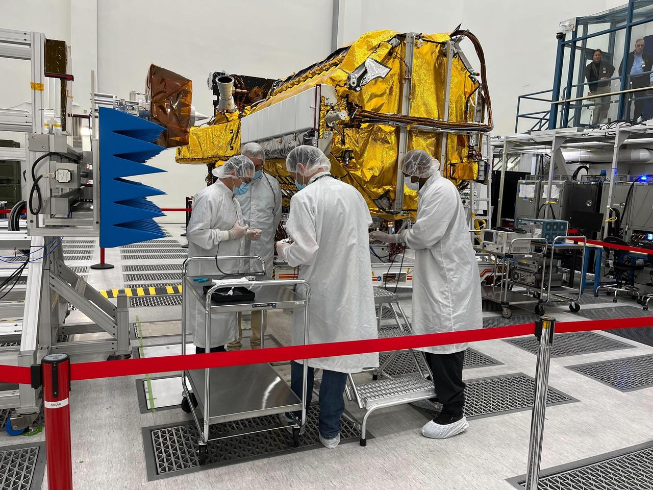
Engineers and technicians from NASA's Jet Propulsion Laboratory work on the NASA-ISRO Synthetic Aperture Radar (NISAR) science instrument payload in a clean room at JPL on Feb. 3, 2023. The payload is scheduled to ship to India in March 2023. The NISAR mission – a joint effort between NASA and ISRO – will measure changes to Earth's land ice surfaces down to fractions of an inch. Data collected by this satellite will help researchers monitor a wide range of changes critical to life on Earth in unprecedented detail. This includes spotting warning signs of imminent volcanic eruptions, helping to monitor groundwater supplies, tracking the melt rate of ice sheets tied to sea level rise, and observing shifts in the distribution of vegetation around the world. The data will inform humanity's responses to urgent challenges posed by natural disasters and climate change, and help communities prepare for and manage hazards. There are two instruments on the satellite that will send and receive radar signals to and from Earth's surface to make the mission's measurements. An L-band synthetic aperture radar (SAR), which uses a signal wavelength of around 9 inches (24 centimeters), and an S-band SAR with a signal wavelength of nearly 5 inches (12 centimeters). Both will bounce their microwave signal off of the planet's surface and record how long it takes the signal to make one roundtrip, as well as the strength of that return signal. This enables the researchers to calculate the distance from the spacecraft to Earth's surface and thereby determine how the land or ice is changing. An antenna reflector nearly 40 feet (12 meters) in diameter, supported by a deployable boom, will focus the microwave signals sent and received by the SARs. JPL, which is managed for NASA by Caltech in Pasadena, leads the U.S. component of NISAR and is providing the mission's L-band SAR instrument. NASA is also providing the radar reflector antenna, the deployable boom, a high-rate communication subsystem for science data, GPS receivers, a solid-state recorder, and payload data subsystem. ISRO is providing the spacecraft bus, the S-band SAR, the launch vehicle, and associated launch services and satellite mission operations. https://photojournal.jpl.nasa.gov/catalog/PIA25771
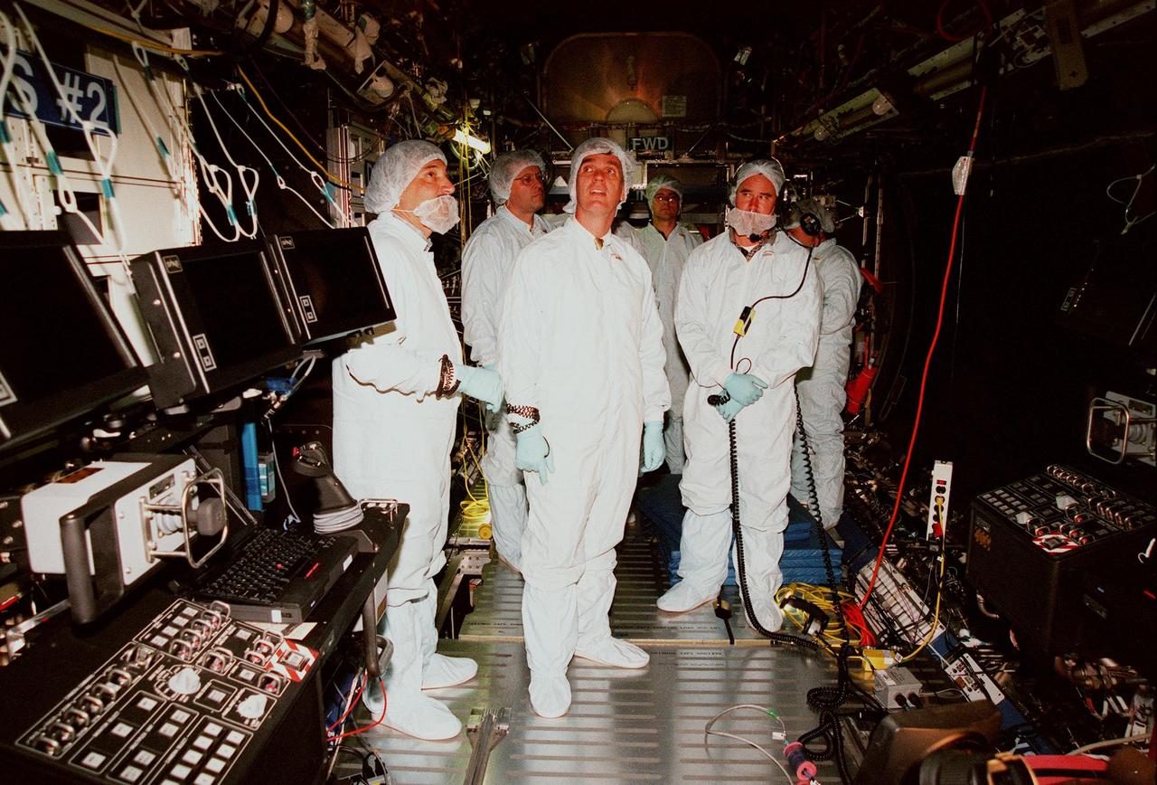
KENNEDY SPACE CENTER, FLA. -- In the Space Station Processing Facility, U.S. Rep. Dave Weldon (center) looks over the U.S. Laboratory, called "Destiny," with a group of Boeing workers. Behind (left) the congressman is Dana Gartzke, the congressman's chief of staff. Weldon is on the House Science Committee and vice chairman of the Space and Aeronautics Subcommittee. Destiny, which will become the centerpiece of scientific research on the ISS, will have five equipment racks aboard to provide essential functions for station systems, including high data-rate communications, and to maintain the station's orientation using control gyroscopes launched earlier. Additional equipment and research racks will be installed in the laboratory on subsequent Shuttle flights. Destiny is scheduled to be launched on Space Shuttle Endeavour in early 2000

The loss of productivity due to flu is staggering. Costs range as much as $20 billio a year. High mutation rates of the flu virus have hindered development of new drugs or vaccines. The secret lies in a small molecule which is attached to the host cell's surface. Each flu virus, no matter what strain, must remove this small molecule to escape the host cell to spread infection. Using data from space and earth grown crystals, researchers from the Center of Macromolecular Crystallography (CMC) are desining drugs to bind with this protein's active site. This lock and key fit reduces the spread of flu in the body by blocking its escape route. In collaboration with its corporate partner, the CMC has refined drug structure in preparation for clinical trials. Tested and approved relief is expected to reach drugstores by year 2004.
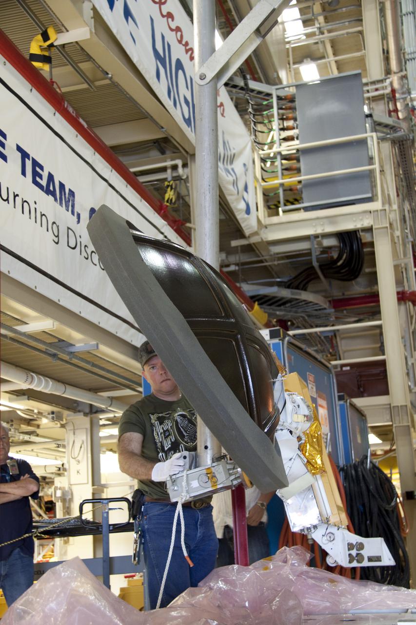
CAPE CANAVERAL, Fla. -- Technicians prepare to install a new Ku-Band communications system antenna on space shuttle Discovery in Orbiter Processing Facility-3 at NASA's Kennedy Space Center in Florida. The antenna is used to transmit and receive high data rate communications, such as video, and is being replaced for the STS-133 mission to the International Space Station. During its STS-131 mission to the station in April, Discovery's Ku-Band failed to operate in orbit. As a result, video of the thermal protection system inspection had to be recorded aboard Discovery and transmitted to the ground after the shuttle docked with the station. Typically, the inspection video is simultaneously transmitted live to the ground and recorded aboard the shuttle for later review. NASA_Charisse Nahser
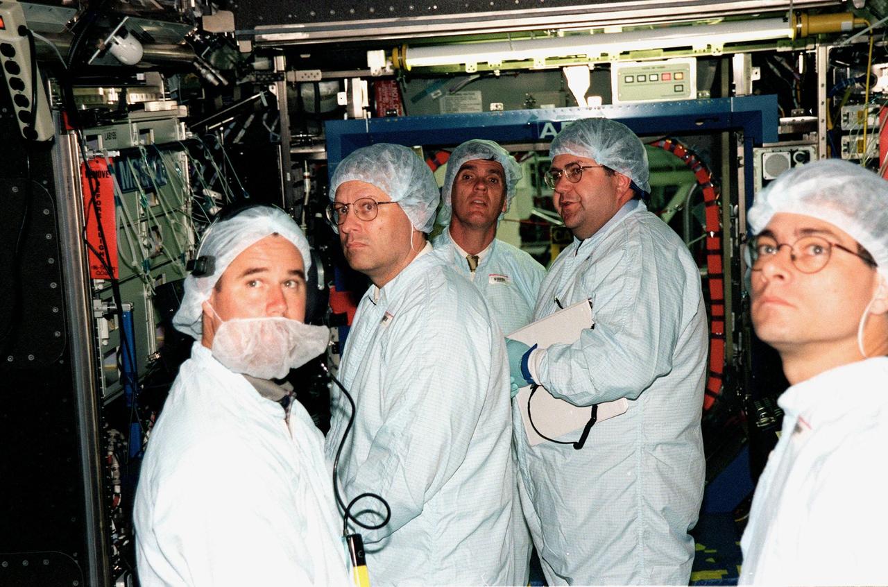
KENNEDY SPACE CENTER, FLA. -- In the Space Station Processing Facility, U.S. Rep. Dave Weldon (center) and his chief of staff Dana Gartzke (second from left) get a close-up look at the interior of the U.S. Lab, called "Destiny." Thomas R. "Randy" Galloway (second from right), with the Space Station Hardware Integration Office, helps with their familiarization of the equipment. They are joined (far left and right) by workers from Boeing. Weldon is on the House Science Committee and vice chairman of the Space and Aeronautics Subcommittee. Destiny is scheduled to be launched on Space Shuttle Endeavour in early 2000. It will become the centerpiece of scientific research on the ISS, with five equipment racks aboard to provide essential functions for station systems, including high data-rate communications, and to maintain the station's orientation using control gyroscopes launched earlier. Additional equipment and research racks will be installed in the laboratory on subsequent Shuttle flights
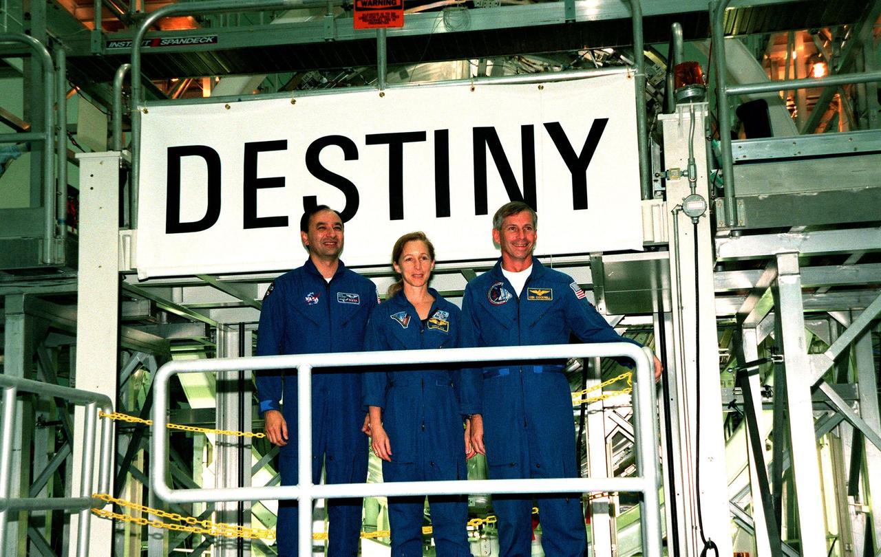
KENNEDY SPACE CENTER, FLA. -- In the Space Station Processing Facility, STS-98 crew members Pilot Mark Polansky, Mission Specialist Marsha Ivins and Commander Ken Cockrell pose underneath the banner revealing the name Destiny given to the U.S. Lab module. They are part of the five-member crew scheduled to carry the lab into space aboard Space Shuttle Endeavour early in the year 2000 where it will become the centerpiece of scientific research on the International Space Station. The Shuttle will spend six days docked to the station while the laboratory is attached and three space walks are conducted to complete its assembly. The laboratory will be launched with five equipment racks aboard, which will provide essential functions for station systems, including high data-rate communications, and maintain the station's orientation using control gyroscopes launched earlier. Additional equipment and research racks will be installed in the laboratory on subsequent Shuttle flights
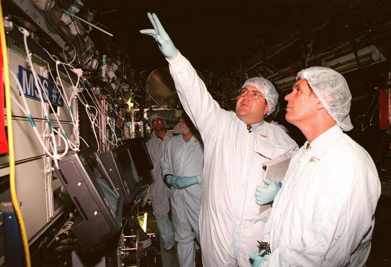
KENNEDY SPACE CENTER, FLA. -- In the Space Station Processing Facility, Thomas R. "Randy" Galloway, with the Space Station Hardware Integration Office, points out a feature to U.S. Rep. Dave Weldon (right) in the U.S. Lab, called "Destiny." In the far background is Dana Gartzke, the congressman's chief of staff. Weldon is on the House Science Committee and vice chairman of the Space and Aeronautics Subcommittee. Destiny is scheduled to be launched on Space Shuttle Endeavour in early 2000. It will become the centerpiece of scientific research on the ISS, with five equipment racks aboard to provide essential functions for station systems, including high data-rate communications, and to maintain the station's orientation using control gyroscopes launched earlier. Additional equipment and research racks will be installed in the laboratory on subsequent Shuttle flights
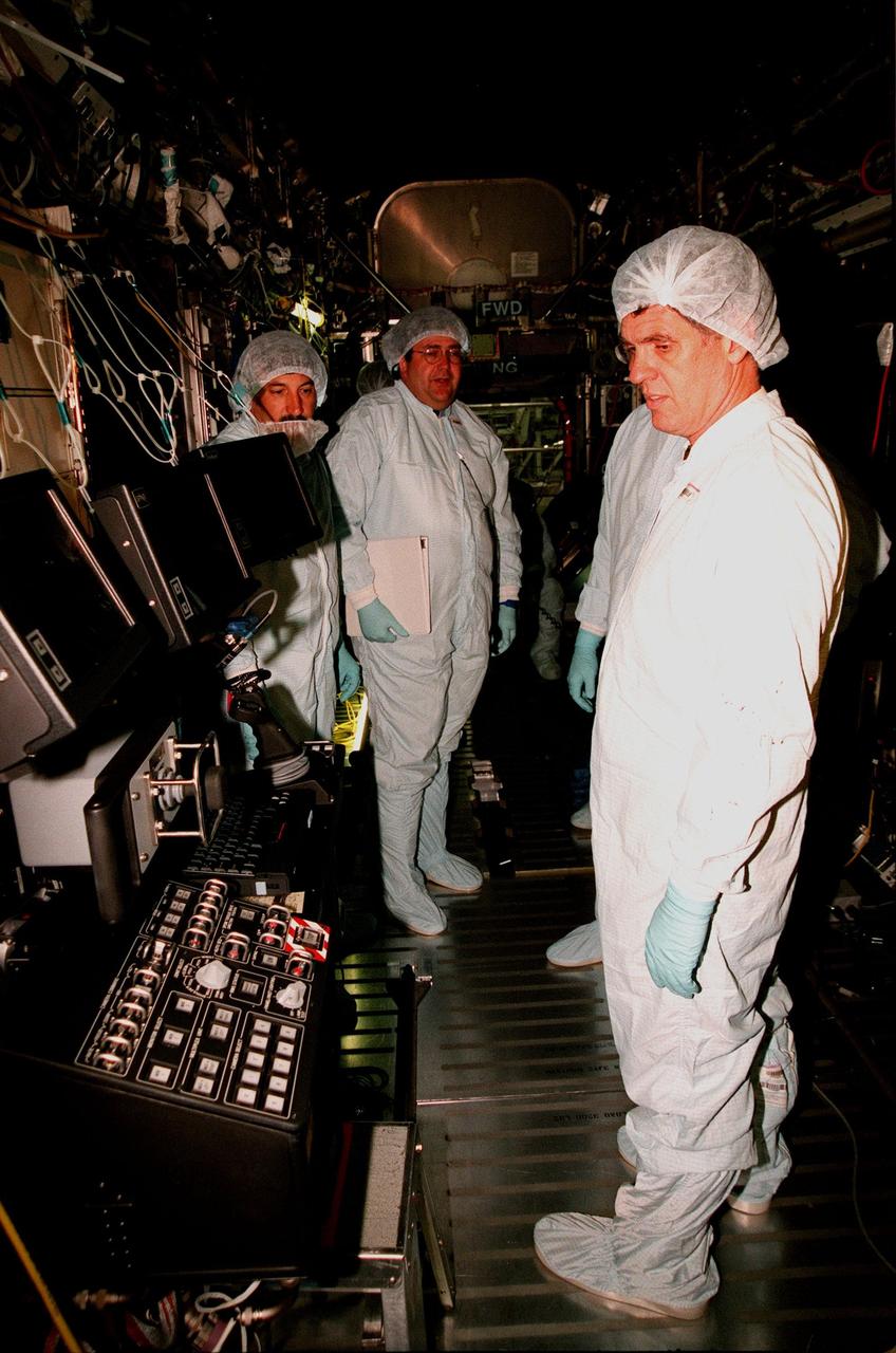
KENNEDY SPACE CENTER, FLA. -- Inside the U.S. Lab, called "Destiny," which is in the Space Station Processing Facility, U.S. Rep. Dave Weldon (right) looks over equipment. In the background (center) is Thomas R. "Randy" Galloway, with the Space Station Hardware Integration Office. Weldon is on the House Science Committee and vice chairman of the Space and Aeronautics Subcommittee. Destiny is scheduled to be launched on Space Shuttle Endeavour in early 2000. It will become the centerpiece of scientific research on the ISS, with five equipment racks aboard to provide essential functions for station systems, including high data-rate communications, and to maintain the station's orientation using control gyroscopes launched earlier. Additional equipment and research racks will be installed in the laboratory on subsequent Shuttle flights